JP7547591B2 - Mold - Google Patents
Mold Download PDFInfo
- Publication number
- JP7547591B2 JP7547591B2 JP2023165906A JP2023165906A JP7547591B2 JP 7547591 B2 JP7547591 B2 JP 7547591B2 JP 2023165906 A JP2023165906 A JP 2023165906A JP 2023165906 A JP2023165906 A JP 2023165906A JP 7547591 B2 JP7547591 B2 JP 7547591B2
- Authority
- JP
- Japan
- Prior art keywords
- cavity
- mold
- injection
- cooling
- protruding
- Prior art date
- Legal status (The legal status is an assumption and is not a legal conclusion. Google has not performed a legal analysis and makes no representation as to the accuracy of the status listed.)
- Active
Links
- 238000001816 cooling Methods 0.000 claims description 68
- 238000002347 injection Methods 0.000 claims description 45
- 239000007924 injection Substances 0.000 claims description 45
- 239000002826 coolant Substances 0.000 claims description 31
- 238000001746 injection moulding Methods 0.000 claims description 20
- 238000000465 moulding Methods 0.000 claims description 14
- 239000011347 resin Substances 0.000 claims description 7
- 229920005989 resin Polymers 0.000 claims description 7
- 239000000463 material Substances 0.000 claims description 6
- 238000005520 cutting process Methods 0.000 claims description 3
- 239000011796 hollow space material Substances 0.000 claims 1
- 238000006243 chemical reaction Methods 0.000 description 24
- 238000009826 distribution Methods 0.000 description 22
- 230000007246 mechanism Effects 0.000 description 22
- 238000000071 blow moulding Methods 0.000 description 11
- 238000010586 diagram Methods 0.000 description 6
- XLYOFNOQVPJJNP-UHFFFAOYSA-N water Substances O XLYOFNOQVPJJNP-UHFFFAOYSA-N 0.000 description 6
- 230000007423 decrease Effects 0.000 description 3
- 238000007664 blowing Methods 0.000 description 2
- 230000008859 change Effects 0.000 description 2
- 238000010438 heat treatment Methods 0.000 description 2
- 230000002452 interceptive effect Effects 0.000 description 2
- 238000004519 manufacturing process Methods 0.000 description 2
- 238000000034 method Methods 0.000 description 2
- 238000004220 aggregation Methods 0.000 description 1
- 230000002776 aggregation Effects 0.000 description 1
- 238000007796 conventional method Methods 0.000 description 1
- 239000000498 cooling water Substances 0.000 description 1
- 238000009792 diffusion process Methods 0.000 description 1
- 238000005516 engineering process Methods 0.000 description 1
- 230000000149 penetrating effect Effects 0.000 description 1
- 238000003825 pressing Methods 0.000 description 1
- 230000008569 process Effects 0.000 description 1
- 230000008719 thickening Effects 0.000 description 1
Images


Classifications
-
- B—PERFORMING OPERATIONS; TRANSPORTING
- B29—WORKING OF PLASTICS; WORKING OF SUBSTANCES IN A PLASTIC STATE IN GENERAL
- B29C—SHAPING OR JOINING OF PLASTICS; SHAPING OF MATERIAL IN A PLASTIC STATE, NOT OTHERWISE PROVIDED FOR; AFTER-TREATMENT OF THE SHAPED PRODUCTS, e.g. REPAIRING
- B29C45/00—Injection moulding, i.e. forcing the required volume of moulding material through a nozzle into a closed mould; Apparatus therefor
- B29C45/17—Component parts, details or accessories; Auxiliary operations
- B29C45/72—Heating or cooling
-
- B—PERFORMING OPERATIONS; TRANSPORTING
- B29—WORKING OF PLASTICS; WORKING OF SUBSTANCES IN A PLASTIC STATE IN GENERAL
- B29C—SHAPING OR JOINING OF PLASTICS; SHAPING OF MATERIAL IN A PLASTIC STATE, NOT OTHERWISE PROVIDED FOR; AFTER-TREATMENT OF THE SHAPED PRODUCTS, e.g. REPAIRING
- B29C45/00—Injection moulding, i.e. forcing the required volume of moulding material through a nozzle into a closed mould; Apparatus therefor
- B29C45/17—Component parts, details or accessories; Auxiliary operations
- B29C45/26—Moulds
-
- B—PERFORMING OPERATIONS; TRANSPORTING
- B29—WORKING OF PLASTICS; WORKING OF SUBSTANCES IN A PLASTIC STATE IN GENERAL
- B29C—SHAPING OR JOINING OF PLASTICS; SHAPING OF MATERIAL IN A PLASTIC STATE, NOT OTHERWISE PROVIDED FOR; AFTER-TREATMENT OF THE SHAPED PRODUCTS, e.g. REPAIRING
- B29C33/00—Moulds or cores; Details thereof or accessories therefor
- B29C33/02—Moulds or cores; Details thereof or accessories therefor with incorporated heating or cooling means
- B29C33/04—Moulds or cores; Details thereof or accessories therefor with incorporated heating or cooling means using liquids, gas or steam
-
- B—PERFORMING OPERATIONS; TRANSPORTING
- B29—WORKING OF PLASTICS; WORKING OF SUBSTANCES IN A PLASTIC STATE IN GENERAL
- B29C—SHAPING OR JOINING OF PLASTICS; SHAPING OF MATERIAL IN A PLASTIC STATE, NOT OTHERWISE PROVIDED FOR; AFTER-TREATMENT OF THE SHAPED PRODUCTS, e.g. REPAIRING
- B29C45/00—Injection moulding, i.e. forcing the required volume of moulding material through a nozzle into a closed mould; Apparatus therefor
- B29C45/17—Component parts, details or accessories; Auxiliary operations
- B29C45/26—Moulds
- B29C45/32—Moulds having several axially spaced mould cavities, i.e. for making several separated articles
-
- B—PERFORMING OPERATIONS; TRANSPORTING
- B29—WORKING OF PLASTICS; WORKING OF SUBSTANCES IN A PLASTIC STATE IN GENERAL
- B29C—SHAPING OR JOINING OF PLASTICS; SHAPING OF MATERIAL IN A PLASTIC STATE, NOT OTHERWISE PROVIDED FOR; AFTER-TREATMENT OF THE SHAPED PRODUCTS, e.g. REPAIRING
- B29C45/00—Injection moulding, i.e. forcing the required volume of moulding material through a nozzle into a closed mould; Apparatus therefor
- B29C45/17—Component parts, details or accessories; Auxiliary operations
- B29C45/72—Heating or cooling
- B29C45/73—Heating or cooling of the mould
- B29C45/7312—Construction of heating or cooling fluid flow channels
-
- B—PERFORMING OPERATIONS; TRANSPORTING
- B29—WORKING OF PLASTICS; WORKING OF SUBSTANCES IN A PLASTIC STATE IN GENERAL
- B29C—SHAPING OR JOINING OF PLASTICS; SHAPING OF MATERIAL IN A PLASTIC STATE, NOT OTHERWISE PROVIDED FOR; AFTER-TREATMENT OF THE SHAPED PRODUCTS, e.g. REPAIRING
- B29C49/00—Blow-moulding, i.e. blowing a preform or parison to a desired shape within a mould; Apparatus therefor
- B29C49/28—Blow-moulding apparatus
-
- B—PERFORMING OPERATIONS; TRANSPORTING
- B29—WORKING OF PLASTICS; WORKING OF SUBSTANCES IN A PLASTIC STATE IN GENERAL
- B29C—SHAPING OR JOINING OF PLASTICS; SHAPING OF MATERIAL IN A PLASTIC STATE, NOT OTHERWISE PROVIDED FOR; AFTER-TREATMENT OF THE SHAPED PRODUCTS, e.g. REPAIRING
- B29C45/00—Injection moulding, i.e. forcing the required volume of moulding material through a nozzle into a closed mould; Apparatus therefor
- B29C45/17—Component parts, details or accessories; Auxiliary operations
- B29C45/72—Heating or cooling
- B29C45/7207—Heating or cooling of the moulded articles
- B29C2045/7214—Preform carriers for cooling preforms
- B29C2045/725—Cooling circuits within the preform carriers
-
- B—PERFORMING OPERATIONS; TRANSPORTING
- B29—WORKING OF PLASTICS; WORKING OF SUBSTANCES IN A PLASTIC STATE IN GENERAL
- B29C—SHAPING OR JOINING OF PLASTICS; SHAPING OF MATERIAL IN A PLASTIC STATE, NOT OTHERWISE PROVIDED FOR; AFTER-TREATMENT OF THE SHAPED PRODUCTS, e.g. REPAIRING
- B29C45/00—Injection moulding, i.e. forcing the required volume of moulding material through a nozzle into a closed mould; Apparatus therefor
- B29C45/17—Component parts, details or accessories; Auxiliary operations
- B29C45/72—Heating or cooling
- B29C45/7207—Heating or cooling of the moulded articles
- B29C2045/7264—Cooling or heating the neck portion of preforms
-
- B—PERFORMING OPERATIONS; TRANSPORTING
- B29—WORKING OF PLASTICS; WORKING OF SUBSTANCES IN A PLASTIC STATE IN GENERAL
- B29C—SHAPING OR JOINING OF PLASTICS; SHAPING OF MATERIAL IN A PLASTIC STATE, NOT OTHERWISE PROVIDED FOR; AFTER-TREATMENT OF THE SHAPED PRODUCTS, e.g. REPAIRING
- B29C45/00—Injection moulding, i.e. forcing the required volume of moulding material through a nozzle into a closed mould; Apparatus therefor
- B29C45/17—Component parts, details or accessories; Auxiliary operations
- B29C45/72—Heating or cooling
- B29C45/73—Heating or cooling of the mould
- B29C45/7312—Construction of heating or cooling fluid flow channels
- B29C2045/7318—Construction of heating or cooling fluid flow channels multilayered fluid channel constructions
-
- B—PERFORMING OPERATIONS; TRANSPORTING
- B29—WORKING OF PLASTICS; WORKING OF SUBSTANCES IN A PLASTIC STATE IN GENERAL
- B29C—SHAPING OR JOINING OF PLASTICS; SHAPING OF MATERIAL IN A PLASTIC STATE, NOT OTHERWISE PROVIDED FOR; AFTER-TREATMENT OF THE SHAPED PRODUCTS, e.g. REPAIRING
- B29C45/00—Injection moulding, i.e. forcing the required volume of moulding material through a nozzle into a closed mould; Apparatus therefor
- B29C45/17—Component parts, details or accessories; Auxiliary operations
- B29C45/72—Heating or cooling
- B29C45/73—Heating or cooling of the mould
- B29C45/7312—Construction of heating or cooling fluid flow channels
- B29C2045/7325—Mould cavity linings for covering fluid channels or provided therewith
-
- B—PERFORMING OPERATIONS; TRANSPORTING
- B29—WORKING OF PLASTICS; WORKING OF SUBSTANCES IN A PLASTIC STATE IN GENERAL
- B29C—SHAPING OR JOINING OF PLASTICS; SHAPING OF MATERIAL IN A PLASTIC STATE, NOT OTHERWISE PROVIDED FOR; AFTER-TREATMENT OF THE SHAPED PRODUCTS, e.g. REPAIRING
- B29C45/00—Injection moulding, i.e. forcing the required volume of moulding material through a nozzle into a closed mould; Apparatus therefor
- B29C45/17—Component parts, details or accessories; Auxiliary operations
- B29C45/26—Moulds
- B29C45/261—Moulds having tubular mould cavities
-
- B—PERFORMING OPERATIONS; TRANSPORTING
- B29—WORKING OF PLASTICS; WORKING OF SUBSTANCES IN A PLASTIC STATE IN GENERAL
- B29K—INDEXING SCHEME ASSOCIATED WITH SUBCLASSES B29B, B29C OR B29D, RELATING TO MOULDING MATERIALS OR TO MATERIALS FOR MOULDS, REINFORCEMENTS, FILLERS OR PREFORMED PARTS, e.g. INSERTS
- B29K2105/00—Condition, form or state of moulded material or of the material to be shaped
- B29K2105/25—Solid
- B29K2105/253—Preform
- B29K2105/258—Tubular
Landscapes
- Engineering & Computer Science (AREA)
- Mechanical Engineering (AREA)
- Manufacturing & Machinery (AREA)
- Physics & Mathematics (AREA)
- Fluid Mechanics (AREA)
- Moulds For Moulding Plastics Or The Like (AREA)
- Blow-Moulding Or Thermoforming Of Plastics Or The Like (AREA)
- Injection Moulding Of Plastics Or The Like (AREA)
Description
本発明は、射出成形用の金型に関する。 The present invention relates to a mold for injection molding.
特許文献1には、給水口と排水口とを1つずつ設けた8列式の成形板の冷却システムが開示されている。具体的には、1本の回路を一時的に2本にして射出キャビティ2列分を同時冷却した後に再び一本化させるという構成を、4回順次繰り返す冷却システムを開示している。また、特許文献2には、2列式のネック型の列間の距離を変換するピッチ変換機構を備える回転搬送型のブロー成形機、及び当該ブロー成形機に使用される2列式の金型が開示されている。
特許文献1に開示の冷却システムでは、給排口が少なく作業性は良いが、単一の回路で8列分の成形板の冷却を行うため、1列目と8列目との水温差がかなり大きくなり冷却条件に差が生じてしまう。
The cooling system disclosed in
また、特許文献2に開示のピッチ変換機構がある回転搬送型のブロー成形機では、3列以上の金型を用いることで、省スペースながら生産性を高くすることができる。しかしながら、当該ブロー成形機ではピッチ変換機構が備えられていることにより、給水口及び排水口を設ける部分が制限され、従来の技術では3列以上の金型の内側の列と外側の列とを同様の条件で冷却することが困難であった。 In addition, in a rotary conveying blow molding machine with a pitch conversion mechanism disclosed in Patent Document 2, by using three or more rows of molds, it is possible to increase productivity while saving space. However, because the blow molding machine is equipped with a pitch conversion mechanism, the areas where water inlets and drainage ports can be installed are limited, and with conventional technology it was difficult to cool the inner and outer rows of three or more rows of molds under the same conditions.
そこで、本発明は、高い冷却能力を確保でき、また冷却条件を均一に近づけることができる射出成形用の金型を提供することを目的とする。 Therefore, the present invention aims to provide a mold for injection molding that can ensure high cooling capacity and make the cooling conditions closer to uniform.
上記課題を解決することのできる本発明の金型は、
複数のキャビティが形成されたキャビティ列を3列以上備え、前記キャビティを冷却する冷却媒体を流通させる冷却流路を備える射出成形用の金型であって、
前記冷却流路は、少なくとも1つ以上の供給口と、前記供給口と連通された分配管と、前記分配管と連通された供給管と、前記供給管と連通され前記キャビティの外周に設けられたキャビティ冷却部と、前記キャビティ冷却部と連通された排出管と、前記排出管と連通された集約管と、前記集約管と連通された少なくとも1つ以上の排出口と、により形成され、
前記供給管及び前記排出管は、前記キャビティ列に平行に、かつ前記キャビティ列毎にそれぞれ少なくとも1つずつ形成されている。
The mold of the present invention that can solve the above problems is as follows:
A mold for injection molding comprising three or more rows of cavities each having a plurality of cavities formed therein, and a cooling flow path for circulating a cooling medium for cooling the cavities,
The cooling flow path is formed by at least one or more supply ports, a distribution pipe connected to the supply port, a supply pipe connected to the distribution pipe, a cavity cooling section connected to the supply pipe and provided on the outer periphery of the cavity, a discharge pipe connected to the cavity cooling section, a collecting pipe connected to the discharge pipe, and at least one or more discharge ports connected to the collecting pipe,
The supply pipe and the discharge pipe are formed in parallel to the cavity rows, and at least one each of the supply pipe and the discharge pipe is formed for each cavity row.
上記構成によれば、高い冷却能力を確保でき、また冷却条件を均一に近づけることができる射出成形用の金型を提供することができる。 The above configuration makes it possible to provide an injection molding die that can ensure high cooling capacity and achieve uniform cooling conditions.
本発明の金型において、
前記供給管及び前記排出管はそれぞれ前記キャビティ列毎に2つずつ形成され、
1つの前記供給管により前記キャビティ列の半分の前記キャビティ冷却部に前記冷却媒体が供給されると好ましい。
In the mold of the present invention,
The supply pipes and the discharge pipes are each formed in pairs for each cavity row,
It is preferable that one of the supply pipes supplies the cooling medium to the cavity cooling portions of half of the cavity row.
上記構成によれば、冷却条件を更に均一に近づけることができる金型を提供することができる。 The above configuration makes it possible to provide a mold that can achieve even more uniform cooling conditions.
本発明の金型において、
前記分配管及び前記集約管はそれぞれ前記供給口及び前記排出口毎に形成され、
各前記分配管及び各前記集約管はそれぞれ独立して形成されていると好ましい。
In the mold of the present invention,
The distribution pipe and the collecting pipe are formed for each of the supply ports and the discharge ports,
It is preferable that each of the distribution pipes and each of the collecting pipes are formed independently.
上記構成によれば、冷却媒体を安定して供給及び排出することができ、冷却を安定して実施できる。 The above configuration allows the cooling medium to be stably supplied and discharged, and cooling can be performed stably.
本発明の金型において、
ネック型の列間の距離を変換するピッチ変換機構を備える成形機用の金型であって、
前記ピッチ変換機構との非干渉部に前記供給口及び前記排出口が形成されていると好ましい。
In the mold of the present invention,
A mold for a molding machine having a pitch conversion mechanism for converting the distance between rows of neck dies,
It is preferable that the supply port and the discharge port are formed in a portion that does not interfere with the pitch changing mechanism.
上記構成によれば、ピッチ変換機構を備える成形機に用いた場合に好適に金型を冷却することができる。 The above configuration allows the mold to be cooled effectively when used in a molding machine equipped with a pitch conversion mechanism.
本発明の金型において、
前記キャビティは、前記金型の凹部に嵌めこまれたインナーキャビティおよびキャビティリングの二つの部材から構成されるインナー部材により規定されていると好ましい。また、前記インナーキャビティは、前記キャビティを規定する内壁面と、射出成形時にネック型と当接する肩部と、を備え、前記キャビティリングは、前記キャビティリングが配置される空洞を内側に有する部材であり、前記肩部と当接する上面部を備え、前記インナーキャビティおよび前記キャビティリングの間に形成される流路が、前記キャビティ冷却部を構成するとさらに好ましい。
In the mold of the present invention,
It is preferable that the cavity is defined by an inner member composed of two members, an inner cavity fitted into a recess of the mold and a cavity ring. It is further preferable that the inner cavity has an inner wall surface that defines the cavity and a shoulder portion that abuts against a neck mold during injection molding, the cavity ring is a member having a hollow inside in which the cavity ring is placed and has an upper surface portion that abuts against the shoulder portion, and a flow path formed between the inner cavity and the cavity ring constitutes the cavity cooling portion.
本発明によれば、高い冷却能力を確保でき、また冷却条件を均一に近づけることができる射出成形用の金型を提供することができる。 The present invention provides an injection molding mold that can ensure high cooling capacity and achieve nearly uniform cooling conditions.
以下、本発明の実施形態の一例について、図面を参照して説明する。尚、本図面に示された各部材の寸法は、説明の便宜上、実際の各部材の寸法とは異なる場合がある。まず、図1を参照して、成形品を製造するための成形機10について説明する。図1は成形機10のブロック図である。
Below, an example of an embodiment of the present invention will be described with reference to the drawings. Note that for the sake of convenience, the dimensions of each component shown in the drawings may differ from the actual dimensions of each component. First, with reference to Figure 1, a
図1に示すように、成形機10は、プリフォームを製造するための射出成形部11と、製造されたプリフォームの温度を調整するための温調部12とを機台18の上に備えている。射出成形部11には、原材料である樹脂材料を供給する射出装置15が接続されている。また、成形機10は、プリフォームをブローして成形品を製造するためのブロー成形部(ブロー装置の一例)13と、製造された成形品を取り出すための取出部14とを備えている。
As shown in FIG. 1, the
射出成形部11と温調部12とブロー成形部13と取出部14とは、搬送手段16を中心として所定角度(本実施形態では90度)ずつ回転した位置に設けられている。搬送手段16は回転板16a等で構成されており、回転板16aにはネック型ガイド部材42およびピッチ変換機構40を介し開閉可能なネック型41が取付けられている。ネック型41によりネック部が支持された状態の成形品(プリフォームや容器)が、回転板16aの
間欠的な回転(90°毎の回転)に伴って各部に搬送されるように構成されている。ネック型41は、複数個で回転板16aに保持される。例えば、1列12個からなるネック型41が3列、回転板16aの径方向に平行に並んで保持される。そして、ネック型ガイド部材42にはピッチ変換機構40が設けられている。ピッチ変換機構40は、二つのネック型ガイド部材42の両端より垂下するリンク機構であり(図4を参照。)、成形の工程に合わせてネック型41の列間の距離を変換できるように構成されている。また、ピッチを広くする広ピッチ変換駆動部17aはブロー成形部13に、ピッチを狭くする狭ピッチ変換駆動部17bは取出部14に設けられる。
The
ここで、図4を参照して、ピッチ変換機構40の具体的な構成や動作を説明する。なお、図4の破線は図面に表されている部材の内部の様子を示す想像線である。ピッチ変換機構40は、被押圧部40aと、リンク部40bと、ネック型保持部40cと、ピッチ維持部40dと、を少なくとも備える。ネック型保持部40cは、外側の列のネック型41を保持し、ネック型ガイド部材42にスライド可能に支持される。中央のネック型41の列は、ネック型ガイド部材42に直接的に支持される。ブロー成形部13で型開きと同時に被押圧部40aの下面が広ピッチ変換駆動部17aの押圧ロッドにより押されると、リンク部40bを介しネック型保持部40cがネック型ガイド部材42の上をスライド移動する。これにより、外側の列のネック型41は中央の列のネック型41と離れる方向に移動し、列間距離(ピッチ)が広がる(広ピッチになる)。そして、この列間距離はピッチ維持部40dにより維持される。次いで、その状態のネック型41が取出部14に移動して成形品が離型されると、狭ピッチ変換駆動部17bにより外側の列のネック型41が中央の列のネック型41に向けてスライド移動し、列間距離(ピッチ)が狭くなり(狭ピッチになり)、ピッチ維持部40dによりその距離が維持される。このように、中央の列のネック型41を静止させ、外側の列のネック型41をスライド移動させることで列間距離を変更させている。なお、狭ピッチは射出成形部11や温調部12のネック型41の列間距離になる。
Here, the specific configuration and operation of the
射出成形部11は、図示を省略する射出キャビティ型、射出コア型、ネック型等を備えている。これらの型が型締めされることで形成されるプリフォーム形状の空間内に、射出装置15から樹脂材料を流し込むことにより、有底のプリフォームが製造されるように構成されている。
The
温調部12は、射出成形部11で製造されたプリフォームの温度を、延伸ブローするための適した温度に加熱して調整するように構成されている。また、温調部12の構成は、加熱ポット式、温調ポット式、赤外線ヒーター式、RED式、電磁波加熱式の何れの様式でも良い。
The
ブロー成形部13は、温調部12で温度調整されたプリフォームに対して、割型からなる金型によって最終ブローを行い、樹脂製の容器を製造するように構成されている。
The
取出部14は、ブロー成形部13で製造された成形品のネック部をネック型から開放して成形品を取り出すように構成されている。
The
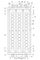
続いて図2及び図3を参照して、射出成形部11に備えられる射出キャビティ型20について説明する。図2はキャビティ型20の平面概略図であり、図3はキャビティ型20の断面図であり、(a)は図2のA-A断面図、(b)は図2のB-B断面図、(c)は図2のC-C断面図を表す。なお、図2及び図3の破線は図面に表されている部材の内部の様子を示す想像線である。
Next, the
射出キャビティ型20は、下方の射出キャビティブロック固定板20aと上方の射出キャビティブロック20bとからなる。射出キャビティブロック20bは、複数(例えば12個)のキャビティ21が形成されたキャビティ列22を少なくとも3列備える。図2では外側のキャビティ列22a、22bおよび内側のキャビティ列22cの位置関係が示されている。また、射出キャビティ型20は、キャビティ21を冷却する冷却媒体を流通させる冷却流路30を内部に備える。冷却媒体としては例えば冷却水を用いることができる。
The
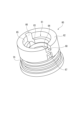
キャビティ21は、射出キャビティ型20の凹部(キャビティ冷却部34)に嵌めこまれた、インナーキャビティ50およびキャビティリング60で構成されるインナー部材によって規定されている。ここで、図5~図7を参照して、インナーキャビティ50およびキャビティリング60について詳細に説明する。図5は、図3の円Aで囲まれた部分のインナー部材の詳細を示す図である。図5に示すようにキャビティリング60の上方に、インナーキャビティ50が載置されている。図6は、インナーキャビティ50を示す断面図である。図7は、キャビティリング60を示す斜視図である。
The
インナーキャビティ50は、図5および図6に示すように、キャビティ21を規定する内壁面51と、ホットランナーからキャビティ21内へ樹脂材料を導入する、内壁面51と連通したゲート部52とを備えている。インナーキャビティ50は、キャビティ21の外周に亘って設けられ、キャビティ21から外側に向かって張出しており、射出成形時にネック型41の下面と当接する肩部53を備えている。インナーキャビティ50は、ゲート部52の外周に亘って設けられ、ゲート部52から外側に向かって張出している脚部54を備えている。インナーキャビティ50は、キャビティ21の外周に亘って設けられ、キャビティ21から外側に向かって張出しており、肩部53および脚部54の間に設けられた胴張出部55を備えている。肩部53、脚部54および胴張出部55は、胴部56により繋がっている。インナーキャビティ50は、肩部53、胴部56および胴張出部55により規定される凹部である第一の流路規定部57を備えている。インナーキャビティ50は、胴張出部55、胴部56および脚部54により規定される凹部である第二の流路規定部58を備えている。肩部53は、キャビティ21の深さH1に対して4分の1以上の厚みH2を持ち、胴張出部55および脚部54よりも厚くされている。第一の流路規定部57および第二の流路規定部58を規定する胴部56は、キャビティ21と冷却媒体とを隔てる部分である。
As shown in Figs. 5 and 6, the
キャビティリング60は、図5および図7に示すように、インナーキャビティ50およびホットランナーが配置される空洞61を内側に備える部材である。キャビティリング60は、インナーキャビティ50の肩部53と当接する上面部62を備える。キャビティリング60は、インナーキャビティ50の胴張出部55が載置される上段差部63を備える。キャビティリング60は、インナーキャビティ50の脚部54が載置される下段差部64を備える。キャビティリング60の内壁65の一部には、上段差部63および上面部62の一部を切り欠くように形成された凹部である第三の流路規定部66が形成されている。第三の流路規定部66の反対側の内壁65には、上段差部63を貫通する第一の貫通孔67および上面部62を切り欠く切欠部68が形成されている。切欠部68の上面に肩部53の下面が載置することで、第二の貫通孔69が構成される。キャビティリング60の外周面には、第一の貫通孔67の下端部に連なるように環状溝70が形成されている。射出キャビティ型20の凹部の内周面と環状溝70が当接することで、第四の流路規定部71が構成される。
As shown in Figs. 5 and 7, the
インナーキャビティ50およびキャビティリング60で構成されるインナー部材が射出キャビティ型20の凹部に嵌めこまれている状態において、脚部54は底面および側面で下段差部64に当接し、胴張出部55は底面および側面で上段差部63に当接し、肩部53は底面で上面部62に当接する。脚部54の側面の下段差部64の側面で形成される凹
部には、液密可能なシール部材が設けられる。この状態において、第一の貫通孔67および第二の流路規定部58が連通し、第二の流路規定部58および第三の流路規定部66が連通し、第三の流路規定部66および第一の流路規定部57が連通し、第一の流路規定部57および第二の貫通孔69が連通している。また、第四の流路規定部71と第一の貫通孔67が連通している。
When the inner member composed of the
冷却流路30は、供給口31と、供給口31と連通された分配管32と、分配管32と連通された供給管33と、供給管33と連通されたキャビティ冷却部34と、キャビティ冷却部34と連通された排出管35と、排出管35と連通された集約管36と、集約管36と連通された排出口37と、により形成されている。供給口31および排出口37には、おのおの冷却媒体を給排させる冷却パイプ38が連結される。なお、供給口31、分配管32、集約管36、および排出口37は射出キャビティブロック固定板20aに設けられおり、供給管33、キャビティ冷却部34、および排出管35は射出キャビティブロック20bに設けられている。つまり、大径である分配管32や集約管36は、小径である供給管33や排出管35に対して下側に配置されており、高さが異なるように設けられている。これにより、射出キャビティブロック20bをピッチ変換機構40(例えばネック型ガイド部材42)と干渉しないように小型化でき、また、単位面積あたりのキャビティ21の数を増やすことができる。
The
供給口31は、キャビティ列22と直交するキャビティ型20の側面23に2つ形成されている。2つの供給口31は、側面23の中央から離れた場所にそれぞれ形成されている。分配管32は射出キャビティ型20においてキャビティ21よりも側面23に近い位置に形成されている。分配管32は供給口31から供給された冷却媒体を3つの流路に分配する。分配管32は2つ形成されており、それぞれが独立して各供給口31と連通している。また各々の分配管32は、外側のキャビティ列22a(22b)と内側のキャビティ列22cとの間に延在している。
Two
供給管33は1つの分配管32に対して3つ形成されており、それぞれが1つの同じ分配管32に連通している。また、それぞれの供給管33は分配管32が延在している範囲で、並列的に設けられている。1つの供給管33はキャビティ列22の半分(6個)のキャビティ冷却部34の下部に連通している。供給口31から見て手前側に位置する半分のキャビティ21の周りに設けられているキャビティ冷却部34に連通している供給管33は、キャビティ列22の半分まで伸びている。供給口31から見て奥側に位置する半分のキャビティ21の周りに設けられているキャビティ冷却部34に連通している供給管33は、供給口31から見て最奥側のキャビティ21付近まで伸びている。
Three
キャビティ冷却部34は、キャビティ21の外周に設けられている。キャビティ冷却部34へ、その下部に連通された供給管33を通して冷却媒体が供給される。また、キャビティ冷却部34の上部には排出管35が連通されている。キャビティ冷却部34から、排出管35を通して冷却媒体が排出される。
The
また、キャビティ冷却部34は、インナーキャビティ50の第一の流路規定部57および第二の流路規定部58、ならびにキャビティリング60の第三の流路規定部66、第一の貫通孔67および切欠部68により構成される(図5)。ここで、キャビティ冷却部34における冷却媒体の挙動を説明する。まず、供給管33からキャビティリング60の第四の流路規定部71と第一の貫通孔67を通して、第二の流路規定部58により規定される流路R1に冷却媒体が導入される。次いで、キャビティリング60の第三の流路規定部66並びにインナーキャビティ50の肩部53、胴張出部55および胴部56により規定される流路R2に冷却媒体が導入される。次に、第一の流路規定部57により規定される流路R3に冷却媒体が導入される。最後に、インナーキャビティ50の肩部53およびキ
ャビティリング60の切欠部68により構成される第二の貫通孔69により規定される流路R4を通り、排出管35へ冷却媒体が排出される。
The
1つの排出管35はキャビティ列22の半分(6個)のキャビティ冷却部34の上部に連通している。排出口37から見て手前側に位置する半分のキャビティ21の周りに設けられているキャビティ冷却部34に連通している排出管35は、キャビティ列22の半分まで伸びている。排出口37から見て奥側に位置する半分のキャビティ21の周りに設けられているキャビティ冷却部34に連通している排出管35は、排出口37から見て最奥側のキャビティ21付近まで伸びている。排出管35は1つの集約管36に対して3つ形成されており、それぞれが1つの同じ集約管36に連通している。また、それぞれの排出管35は集約管36が延在している範囲で、並列的に設けられている。
One
集約管36は、射出キャビティ型20においてキャビティ21よりも側面23に近い位置に形成されている。集約管36は3つの排出管35から排出された冷却媒体を1つの流路に集約する。集約管36は2つ形成されており、それぞれが独立して各排出口37と連通している。排出口37は、側面23に2つ形成されている。2つの排出口37は、側面23の中央から離れた場所にそれぞれ形成されている。また各々の集約管36は、外側のキャビティ列22a(22b)と内側のキャビティ列22cとの間に延在している。
The collecting
供給口31が形成された側面23及び排出口37が形成された側面23は、対向している。また、排出管35は、供給管33に比べてキャビティ21が形成された射出キャビティ型20の上面24の近くに形成されている。分配管32及び集約管36は、供給管33よりも上面24と対向する射出キャビティ型20の底面25の近くに形成されている。分配管32及び集約管36は略同径で形成され、供給管33及び排出管35は略同径で形成されている。分配管32は供給管33より太く、集約管36は排出管35より太く形成されている。
The
図4は、本実施形態の射出キャビティ型20にピッチ変換機構40を備えるネック型41が型締めされている様子を表す図である。ピッチ変換機構40は、射出キャビティ型20にネック型41を型締めする際に、側面23の中央近傍に配置される。供給口31及び排出口37は、ピッチ変換機構に接触しない非干渉部に形成されている。なお、射出キャビティ型20には、機台18の上に固定されたホットランナー80を介し射出装置15から溶融樹脂が導入される。
上記の構成により、一つの分配管32からの冷却媒体を外側のキャビティ列22a(22b)および内側のキャビティ列22cに好適に分配して供給することが可能となり、また、外側のキャビティ列22a(22b)および内側のキャビティ列22cの冷却媒体を集約させて一つの集約管36から排出することが可能になる。
4 is a diagram showing a state in which a
With the above configuration, it is possible to appropriately distribute and supply the cooling medium from one
ところで、従来の供給口及び排出口が少なく、連続した回路で複数のキャビティ列の冷却を行う冷却流路を備えた金型では、供給口付近の冷却媒体の温度と排出口付近の冷却媒体の温度との差が大きくなってしまうおそれがあった。それにより冷却条件にむらが生じてしまい、また下流のキャビティを十分に冷却できなくなるおそれがあった。大口の供給口、供給管、排出口及び排出管を形成すれば水量を増やすことができ、冷却条件を均一に近づけることが可能だが、金型内で冷却流路が占める割合が大きくなり、射出成形できる成形品の大きさや形状が限定されてしまう。 However, in conventional molds with few supply and discharge ports and cooling flow paths that cool multiple rows of cavities in a continuous circuit, there was a risk of a large difference in temperature between the cooling medium near the supply port and the cooling medium near the discharge port. This could lead to uneven cooling conditions and the risk of not being able to sufficiently cool downstream cavities. By forming large supply ports, supply pipes, discharge ports, and discharge pipes, the amount of water can be increased and the cooling conditions can be made closer to uniform, but the proportion of the mold that is taken up by the cooling flow paths increases, limiting the size and shape of the molded products that can be injection molded.
本実施形態の射出キャビティ型20によれば、2つの供給口31及び排出口37を有する冷却流路30を備えることにより、冷却流路を太くすることなく水量を多くでき、高い冷却能力を確保できる。また、供給管33及び排出管35をキャビティ列22に平行に設け、かつキャビティ列22毎にそれぞれ少なくとも1つずつ設けていることにより、各キ
ャビティ列22での冷却条件を均一に近づけることができ、射出キャビティ型20の冷却条件を均一に近づけることができる。
According to the
また、本実施形態の射出キャビティ型20によれば、キャビティ列22の半分のキャビティ冷却部34に対して各供給管33から冷却媒体が供給されるので、一本の供給管33当たりのキャビティ冷却部34を減らすことができ、各キャビティ21での冷却条件を均一に近づけることができ、射出キャビティ型20の冷却条件を更に均一に近づけることができる。また、一本あたりの供給管33の直径を小さくできるため、金型内の冷却流路の配置構成における融通性が高まり、成形品の大きさや形状等に関する制限を減少させることもできる。
In addition, according to the
また、本実施形態の射出キャビティ型20によれば、供給口31及び排出口37毎に分配管32及び集約管36がそれぞれ独立して形成されているので、冷却媒体を安定して供給及び排出することができ、冷却を安定して実施できる。
In addition, according to the
また、ピッチ変換機構を備える成形機では、射出成形時に型閉状態で金型の列と直交する面の中央付近にピッチ変換機構が配置される。そのため、給水口及び排水口を形成できる場所が制限される。従来の方法では、当該成形機において金型に3列以上のキャビティ列を設けると金型の内側のキャビティ列を外側のキャビティ列と同様の冷却条件で均一に冷却することが困難であった。本実施形態の射出キャビティ型20によれば、ピッチ変換機構40との非干渉部に供給口31及び排出口37が形成されて、供給管33及び排出管35が、キャビティ列22に平行に、かつキャビティ列22毎に形成されているので、ピッチ変換機構40を備える成形機10に用いた場合に好適に金型を冷却することができる。
In addition, in a molding machine equipped with a pitch conversion mechanism, the pitch conversion mechanism is placed near the center of the plane perpendicular to the rows of molds when the mold is closed during injection molding. This limits the locations where the water supply and drain ports can be formed. In the conventional method, when the mold is provided with three or more rows of cavities in the molding machine, it is difficult to uniformly cool the inner row of cavities of the mold under the same cooling conditions as the outer row of cavities. According to the
また、キャビティを規定するインナー部材は、射出成形時にキャビティ型とネック型とコア型(図示無)を型締めする際の型締め圧力に対抗するためにある程度の強度が要求される。また、インナー部材は内部に冷却媒体が通されて射出成形されたプリフォームを冷却する。冷却効率を上げる観点から、インナー部材の内部を流れる冷却媒体はできるだけインナー部材の内壁面に近い箇所を流路とすることが望ましい。しかしながら、一つの部材で構成されるインナー部材において内壁面に近い箇所に冷却媒体の流路を形成すると、インナー部材の内壁面に近い部分の厚みが局所的に小さくなってその部分での強度(剛性度)が減少してしまい、型締め圧力に耐えることができなくなる。拡散接合方式によりキャビティ近傍に冷流路を配したインナー部材を製造することも可能だが、コスト高に繋がり、接合度合が不十分だと冷却媒体の漏れに繋がる。また、射出成形時には、インナー部材の下に位置するホットランナーからの熱が伝わるため、一つの部材で構成されるインナー部材では冷却効率が下がる恐れがある。 The inner member that defines the cavity is required to have a certain degree of strength to withstand the clamping pressure when the cavity mold, neck mold, and core mold (not shown) are clamped during injection molding. A cooling medium is passed through the inner member to cool the injection molded preform. From the viewpoint of increasing cooling efficiency, it is desirable for the cooling medium flowing inside the inner member to be as close to the inner wall surface of the inner member as possible. However, if a cooling medium flow path is formed near the inner wall surface of an inner member made of one member, the thickness of the part near the inner wall surface of the inner member becomes locally small, and the strength (rigidity) of that part decreases, making it impossible to withstand the clamping pressure. It is also possible to manufacture an inner member with a cold flow path arranged near the cavity by the diffusion bonding method, but this leads to high costs and leakage of the cooling medium if the degree of bonding is insufficient. In addition, during injection molding, heat is transferred from the hot runner located under the inner member, so that the cooling efficiency may decrease in an inner member made of one member.
本実施形態の射出キャビティ型20では、インナー部材がインナーキャビティ50およびキャビティリング60の2つの部材で構成されている。これにより、ホットランナーからの熱がキャビティリング60で中断されてインナーキャビティ50に伝わる熱を少なくしているため、一つの部材で構成されるインナー部材を用いる場合に比べて冷却効率が下がることを抑制できる。
In the
また、インナーキャビティ50の肩部53に厚みを持たせ、インナー部材が射出キャビティ型20の凹部に嵌めこまれている状態において、肩部53は底面でキャビティリング60の上面部62に当接している。型締め圧力に対して対抗するための接地面積を稼ぎ、且つ圧力がかかる肩部を厚くしたことにより、キャビティ21と型締め圧力に対抗するために必要な強度を確保することができる。そして、インナーキャビティ50とキャビティリング60を別部材としたことにより、必要な強度を確保しつつ、キャビティ21と冷却
媒体を隔てる胴部56を薄くして冷却媒体を内壁面51に近い箇所で流すことができる。これにより、高い冷却効率を達成できる。
In addition, the
なお、射出成形における型締め圧力は、キャビティ単体の断面積およびキャビティの個数に対応して設定される。この型締め圧力に対抗することのできる強度(剛性度)を、ネック型等と当接するインナーキャビティの肩部に備えさせるために、肩部に厚みを持たせる必要がある。一つの部材で構成されるインナー部材(インナーキャビティ単体)であると、それ自体で型締め圧力に対抗するために肩部の厚みを大きくする必要がある。これに対して、インナーキャビティ50とキャビティリング60とによりインナー部材を構成する上記の実施形態によれば、インナーキャビティ50の肩部53にかかる型締め圧力をキャビティリング60が受けることができる。これにより、一つの部材で構成されるインナー部材の場合と比較して、肩部53の厚みを薄くすることができる。これにより、冷却媒体用の冷却回路をキャビティ21の内壁面の側により近づけることができ、射出キャビティ型20の冷却効率を高めることができる。
The clamping pressure in injection molding is set according to the cross-sectional area of the cavity and the number of cavities. In order to provide the shoulder of the inner cavity that contacts the neck mold with the strength (rigidity) required to withstand this clamping pressure, it is necessary to make the shoulder thicker. If the inner member (inner cavity alone) is made of a single member, the thickness of the shoulder needs to be increased in order to withstand the clamping pressure by itself. In contrast, according to the above embodiment in which the inner member is made of the
なお、本発明は、上述した実施形態に限定されず、適宜、変形、改良等が自在である。その他、上述した実施形態における各構成要素の材質、形状、寸法、数値、形態、数、配置場所等は、本発明を達成できるものであれば任意であり、限定されない。
例えば、分配管32や集約管36を、それぞれ外側の二つのキャビティ列22a、22bの間にわたって延在する単一(一本)の構成にし、そこに2つ以上の供給口31や排出口37を設けた構成にしても良い。また、前述の構成の場合、十分な冷却能力が満たされるようであれば、供給口31や排出口37はそれぞれ1つずつにしても構わない。
The present invention is not limited to the above-described embodiment, and can be freely modified, improved, etc. as appropriate. The material, shape, size, numerical value, form, number, location, etc. of each component in the above-described embodiment are arbitrary and not limited as long as the present invention can be achieved.
For example, the
なお、本願は、2017年9月8日付で出願された日本国特許出願(特願2017-173440)に基づいており、その全体が引用により援用される。また、ここに引用されるすべての参照は全体として取り込まれる。 This application is based on a Japanese patent application (Patent Application No. 2017-173440) filed on September 8, 2017, the entirety of which is incorporated by reference. In addition, all references cited herein are incorporated in their entirety.
10:成形機、11:射出成形部、12:温調部、13:ブロー成形部、14:取出部、15:射出装置、16:搬送手段、16a:回転板、20:射出キャビティ型、21:キャビティ、22:キャビティ列、23:側面、24:上面、25:底面、30:冷却流路、31:供給口、32:分配管、33:供給管、34:キャビティ冷却部、35:排出管、36:集約管、37:排出口、40:ピッチ変換機構、41:ネック型、42:ネック型ガイド部材 10: molding machine, 11: injection molding section, 12: temperature control section, 13: blow molding section, 14: removal section, 15: injection device, 16: conveying means, 16a: rotating plate, 20: injection cavity mold, 21: cavity, 22: cavity row, 23: side, 24: top surface, 25: bottom surface, 30: cooling flow path, 31: supply port, 32: distribution pipe, 33: supply pipe, 34: cavity cooling section, 35: discharge pipe, 36: collection pipe, 37: discharge port, 40: pitch conversion mechanism, 41: neck mold, 42: neck mold guide member
Claims (10)
凹部が形成された射出キャビティブロックと、
前記凹部に嵌め込まれたインナー部材と、
を備えており、
前記射出キャビティブロックは、前記凹部に連通する冷却媒体の供給管と排出管とを備えており、
前記インナー部材は、
樹脂材料が注入されるキャビティを規定する部分を有しているインナーキャビティと、
前記インナーキャビティが配置される空洞を区画する内壁を有しており、当該内壁と前記インナーキャビティの外面との間に前記キャビティを冷却するための冷却媒体を流通させるための冷却流路を規定するキャビティリングと、
を備えている、
金型。 A mold including an injection cavity mold for injection molding a container preform,
an injection cavity block having a recess formed therein;
an inner member fitted in the recess;
Equipped with
the injection cavity block includes a supply pipe and a discharge pipe for a cooling medium that communicate with the recess;
The inner member is
an inner cavity having a portion defining a cavity into which a resin material is injected;
a cavity ring having an inner wall that defines a hollow space in which the inner cavity is disposed, and defining a cooling flow path between the inner wall and an outer surface of the inner cavity for circulating a cooling medium for cooling the cavity;
Equipped with
Mold.
第一方向に前記空洞と連通するゲート部と、
前記第一方向に前記ゲート部と連通して前記キャビティの一部を規定する内壁面と、
を備えており、
前記冷却流路を規定する複数の溝部が、前記第一方向に並ぶように前記外面に形成されている、
請求項1に記載の金型。 The inner cavity is
a gate portion communicating with the cavity in a first direction;
an inner wall surface that communicates with the gate portion in the first direction and defines a portion of the cavity;
Equipped with
A plurality of grooves defining the cooling flow passages are formed on the outer surface so as to be aligned in the first direction.
The mold according to claim 1.
前記インナーキャビティの第一部分と当接する第一当接部と、
前記インナーキャビティにおける前記第一部分よりも第一方向に離れた位置にある第二部分と当接する第二当接部と、
前記第一部分と前記第二部分の間において前記冷却流路を形成するように前記第一方向に延びている溝部と、
が形成されている、
請求項1に記載の金型。 The inner wall of the cavity ring has:
a first abutment portion that abuts against a first portion of the inner cavity;
a second contact portion that contacts a second portion of the inner cavity that is located farther in a first direction than the first portion;
a groove extending in the first direction to define the cooling flow passage between the first portion and the second portion;
is formed,
The mold according to claim 1.
前記外面から前記第一方向と交差する第二方向へ突出する胴張出部と、
前記胴張出部よりも前記ゲート部に近い位置において前記外面から前記第二方向へ突出する脚部と、
前記胴張出部よりも前記ゲート部から離れた位置において前記外面から前記第二方向へ突出する肩部と、
を備えており、
前記胴張出部の前記第二方向に沿う幅寸法は、前記脚部の前記第二方向に沿う幅寸法よりも大きく、前記肩部の前記第二方向に沿う幅寸法よりも小さい、
請求項2に記載の金型。 The inner cavity is
A trunk protrusion protruding from the outer surface in a second direction intersecting the first direction;
a leg portion protruding from the outer surface in the second direction at a position closer to the gate portion than the trunk protrusion portion;
a shoulder portion protruding from the outer surface in the second direction at a position farther from the gate portion than the trunk protrusion portion;
Equipped with
A width dimension of the torso protruding portion along the second direction is larger than a width dimension of the leg portion along the second direction and smaller than a width dimension of the shoulder portion along the second direction.
The mold according to claim 2.
前記空洞と前記供給管を連通する第一開口部と、
前記空洞と前記排出管を連通する第二開口部と、
前記内壁に設けられた複数の段差部と、
を備えており、
前記第二開口部は、前記第二当接部および前記段差部の一部を切り欠くように形成されている、
請求項3に記載の金型。 The cavity ring comprises:
a first opening communicating the cavity with the supply pipe;
A second opening communicating the cavity with the exhaust pipe;
A plurality of step portions provided on the inner wall;
Equipped with
The second opening is formed by cutting out a part of the second contact portion and the step portion.
The mold according to claim 3.
前記第一方向に前記空洞と連通するゲート部と、
前記外面から前記第一方向と交差する第二方向へ突出する胴張出部と、
前記胴張出部よりも前記ゲート部に近い位置において前記外面から前記第二方向へ突出する脚部と、
前記胴張出部よりも前記ゲート部から離れた位置において前記外面から前記第二方向へ突出する肩部と、
を備えており、
前記肩部は、前記第二当接部に当接し、
前記胴張出部と前記脚部は、前記複数の段差部に当接している、
請求項5に記載の金型。 The inner cavity is
a gate portion communicating with the cavity in the first direction;
A trunk protrusion protruding from the outer surface in a second direction intersecting the first direction;
a leg portion protruding from the outer surface in the second direction at a position closer to the gate portion than the trunk protrusion portion;
a shoulder portion protruding from the outer surface in the second direction at a position farther from the gate portion than the trunk protrusion portion;
Equipped with
The shoulder portion abuts against the second abutment portion,
The body extension portion and the leg portion abut against the plurality of step portions.
The mold according to claim 5.
前記インナーキャビティは、
第一方向に前記空洞と連通するゲート部と、
前記外面から前記第一方向と交差する第二方向へ突出する胴張出部と、
前記胴張出部よりも前記ゲート部に近い位置において前記外面から前記第二方向へ突出する脚部と、
前記胴張出部よりも前記ゲート部から離れた位置において前記外面から前記第二方向へ突出しており、前記インナーキャビティに当接しつつ前記ネック型による型締め圧力を受ける肩部と、
を備えており、
前記肩部の前記第一方向に沿う厚み寸法は、前記胴張出部と前記脚部の前記第一方向に沿う厚み寸法よりも大きい、
請求項1に記載の金型。 a neck mold clamped to the injection cavity mold,
The inner cavity is
a gate portion communicating with the cavity in a first direction;
A trunk protrusion protruding from the outer surface in a second direction intersecting the first direction;
a leg portion protruding from the outer surface in the second direction at a position closer to the gate portion than the trunk protrusion portion;
a shoulder portion protruding from the outer surface in the second direction at a position farther from the gate portion than the trunk protrusion portion, and receiving a mold clamping pressure from the neck mold while contacting the inner cavity;
Equipped with
A thickness dimension of the shoulder portion along the first direction is greater than thickness dimensions of the trunk extension portion and the leg portion along the first direction.
The mold according to claim 1.
請求項1から請求項7のいずれか一項に記載の金型。 and an injection core mold that is clamped with the injection cavity mold to form a molding space corresponding to the shape of the preform.
A mold according to any one of claims 1 to 7.
請求項1から請求項8のいずれか一項に記載の金型。 a hot runner for injecting the resin material into the cavity;
A mold according to any one of claims 1 to 8.
請求項1から請求項9のいずれか一項に記載の金型。 the injection cavity mold includes a plurality of cavity rows, and a plurality of the cavities are arranged in each of the plurality of cavity rows;
A mold according to any one of claims 1 to 9.
Applications Claiming Priority (4)
| Application Number | Priority Date | Filing Date | Title |
|---|---|---|---|
| JP2017173440 | 2017-09-08 | ||
| JP2017173440 | 2017-09-08 | ||
| JP2019541016A JP7130652B2 (en) | 2017-09-08 | 2018-09-07 | Mold |
| JP2022133196A JP7390448B2 (en) | 2017-09-08 | 2022-08-24 | Mold |
Related Parent Applications (1)
| Application Number | Title | Priority Date | Filing Date |
|---|---|---|---|
| JP2022133196A Division JP7390448B2 (en) | 2017-09-08 | 2022-08-24 | Mold |
Publications (2)
| Publication Number | Publication Date |
|---|---|
| JP2023168436A JP2023168436A (en) | 2023-11-24 |
| JP7547591B2 true JP7547591B2 (en) | 2024-09-09 |
Family
ID=65634877
Family Applications (3)
| Application Number | Title | Priority Date | Filing Date |
|---|---|---|---|
| JP2019541016A Active JP7130652B2 (en) | 2017-09-08 | 2018-09-07 | Mold |
| JP2022133196A Active JP7390448B2 (en) | 2017-09-08 | 2022-08-24 | Mold |
| JP2023165906A Active JP7547591B2 (en) | 2017-09-08 | 2023-09-27 | Mold |
Family Applications Before (2)
| Application Number | Title | Priority Date | Filing Date |
|---|---|---|---|
| JP2019541016A Active JP7130652B2 (en) | 2017-09-08 | 2018-09-07 | Mold |
| JP2022133196A Active JP7390448B2 (en) | 2017-09-08 | 2022-08-24 | Mold |
Country Status (7)
| Country | Link |
|---|---|
| US (2) | US11685093B2 (en) |
| EP (1) | EP3680084B1 (en) |
| JP (3) | JP7130652B2 (en) |
| KR (1) | KR102339155B1 (en) |
| CN (2) | CN114750364B (en) |
| TW (1) | TWI681858B (en) |
| WO (1) | WO2019049970A1 (en) |
Families Citing this family (1)
| Publication number | Priority date | Publication date | Assignee | Title |
|---|---|---|---|---|
| JP2026059189A (en) * | 2024-09-26 | 2026-04-07 | 住友重機械工業株式会社 | injection molding equipment |
Citations (8)
| Publication number | Priority date | Publication date | Assignee | Title |
|---|---|---|---|---|
| JP2000202897A (en) | 1999-01-18 | 2000-07-25 | Taisei Kako Kk | Injection blow molding system and mold structure in hot parison molding method |
| JP2006015728A (en) | 2004-06-03 | 2006-01-19 | Toyo Tire & Rubber Co Ltd | Joint boot manufacturing method |
| JP2006068956A (en) | 2004-08-31 | 2006-03-16 | Aoki Technical Laboratory Inc | Cooling structure of cavity bottom part of injection mold |
| JP2008502500A (en) | 2004-06-14 | 2008-01-31 | ハスキー インジェクション モールディング システムズ リミテッド | Cooling circuit for cooling the neck ring of the preform |
| JP2010253792A (en) | 2009-04-24 | 2010-11-11 | Konica Minolta Opto Inc | Mold for optical elements |
| JP2011156728A (en) | 2010-01-29 | 2011-08-18 | Nissei Asb Mach Co Ltd | Blow mold unit and blow molding machine using the same |
| JP2016179700A (en) | 2016-07-22 | 2016-10-13 | パンチ工業株式会社 | Molding die of preform, and cooling method of preform |
| JP2019072903A (en) | 2017-10-13 | 2019-05-16 | 大日本印刷株式会社 | Preform, plastic bottle and method for producing the same |
Family Cites Families (66)
| Publication number | Priority date | Publication date | Assignee | Title |
|---|---|---|---|---|
| US3930779A (en) * | 1974-01-15 | 1976-01-06 | Farrell Patent Company | Injection molding apparatus with improved cooling |
| DE2640607B1 (en) * | 1976-09-09 | 1977-12-22 | Robert Hanning | Method and mold for cooling moldings made of plastic |
| JPS5939510A (en) | 1982-08-31 | 1984-03-03 | Katashi Aoki | Adjustment of mold temperature |
| CA2603238A1 (en) | 1994-06-21 | 1995-12-22 | Jobst Ulrich Gellert | Injection molding gate and cavity insert |
| US5702734A (en) * | 1994-12-19 | 1997-12-30 | Electra Form, Inc. | Take-out and cooling apparatus |
| JPH08290466A (en) * | 1995-04-25 | 1996-11-05 | Sanko Seikei Kk | Mold for molding sheet |
| US5795529A (en) * | 1995-05-31 | 1998-08-18 | Acushnet Company | Fast thermal response mold |
| CA2160644C (en) * | 1995-10-16 | 2005-05-24 | Jobst Ulrich Gellert | Cooled thread split inserts for injection molding preforms |
| CA2257986A1 (en) * | 1996-06-11 | 1997-12-18 | Otto Hofstetter Ag | Ejection device |
| US5941054A (en) * | 1997-10-16 | 1999-08-24 | The Elizabeth And Sandor Valyi Foundation, Inc. | Method for producing filled rigid containers of plastic |
| JPH11213457A (en) * | 1998-01-20 | 1999-08-06 | Toray Ind Inc | Optical disk substrate manufacturing apparatus, optical disk substrate manufacturing method, and optical disk |
| CA2228458C (en) | 1998-02-02 | 2008-08-05 | Mold-Masters Limited | Injection molding cooled gate insert |
| CA2239349A1 (en) * | 1998-05-29 | 1999-11-29 | Denis Babin | Injection molding apparatus having nozzles with elongated mounting flanges |
| USRE38396E1 (en) * | 1998-07-29 | 2004-01-27 | Jobst Ulrich Gellert | Method of making injection molding cooled thread split inserts |
| CA2244511C (en) * | 1998-07-29 | 2008-12-23 | Jobst Ulrich Gellert | Method of making injection molding cooled thread split inserts |
| JP4266434B2 (en) * | 1999-04-12 | 2009-05-20 | 日精エー・エス・ビー機械株式会社 | Preform cooling device |
| JP3977565B2 (en) * | 1999-05-06 | 2007-09-19 | 小野産業株式会社 | Mold for synthetic resin molding, mold temperature control device and mold temperature control method |
| DE10210456A1 (en) * | 2002-03-09 | 2003-09-18 | Mht Mold & Hotrunner Tech Ag | System for cooling sleeves attached to a carrier plate |
| DE10240419B3 (en) * | 2002-09-02 | 2004-04-22 | Fraunhofer-Gesellschaft zur Förderung der angewandten Forschung e.V. | Flat cooling unit based on the counterflow principle |
| CN100441392C (en) * | 2002-12-12 | 2008-12-10 | 阿姆诺洼化学有限公司 | Method for designing and manufacturing a mould |
| DE10305669A1 (en) * | 2003-02-12 | 2004-08-26 | Mht Mold & Hotrunner Technology Ag | Cooling system for multiple tools, especially for blow molding preforms, has the flow path arranged to cool tool parts partially in series |
| JP4319962B2 (en) * | 2004-10-04 | 2009-08-26 | 日精エー・エス・ビー機械株式会社 | Stretch blow molding equipment |
| US7293980B2 (en) * | 2005-03-10 | 2007-11-13 | Husky Injection Molding Systems Ltd. | Porous member for a post-molding molded article conditioning apparatus with an integrally formed cooling structure |
| US20060215809A1 (en) | 2005-03-22 | 2006-09-28 | General Electric Company | System and method for motion and angulation profiles in tomosynthesis |
| CA2509181C (en) * | 2005-06-03 | 2009-04-28 | Husky Injection Molding Systems Ltd. | A mold split insert |
| ITMO20050224A1 (en) * | 2005-09-07 | 2007-03-08 | Sacmi | MOLDS FOR MOLDING OF PLASTIC ITEMS AND METHOD TO PRODUCE A MOLD ELEMENT |
| WO2007034815A1 (en) * | 2005-09-21 | 2007-03-29 | Mitsubishi Heavy Industries, Ltd. | Mold, mold temperature regulation method, mold temperature regulation device, injection molding method, injection molding machine, and thermoplastic resin sheet |
| DE102006004928A1 (en) * | 2006-02-01 | 2007-08-16 | Mht Mold & Hotrunner Technology Ag | Improved neck back cooling |
| DE102006028149A1 (en) * | 2006-06-16 | 2007-12-20 | Mht Mold & Hotrunner Technology Ag | Formnestkavität with decoupled cooling duct guide |
| DE202007008217U1 (en) * | 2006-06-29 | 2007-09-13 | Netstal-Maschinen Ag | Auxiliary device with gripper with a variety of nipples |
| CN201040416Y (en) * | 2007-05-29 | 2008-03-26 | 郭学文 | Improved structure of die |
| US7645132B2 (en) * | 2007-09-07 | 2010-01-12 | Husky Injection Molding Systems Ltd. | Mold insert and mold stack for use with molding machine |
| JP5437659B2 (en) * | 2008-02-20 | 2014-03-12 | 住友化学株式会社 | Heater and resin molding device |
| JP5697885B2 (en) | 2009-09-11 | 2015-04-08 | 日精エー・エス・ビー機械株式会社 | Blow molding machine |
| KR100963191B1 (en) * | 2009-09-15 | 2010-06-14 | 이재복 | Baffle pipe and core cooling apparatus of injection mold |
| CN201597134U (en) * | 2009-10-28 | 2010-10-06 | 杨东佐 | Mould heating and cooling device |
| KR101157511B1 (en) * | 2010-05-24 | 2012-06-21 | 주식회사 나다이노베이션 | Forming mold and molding system having the same |
| KR20120034398A (en) * | 2010-10-01 | 2012-04-12 | 삼성전자주식회사 | Cooling apparatus for injection mold and injection mold having the same |
| US8512625B2 (en) * | 2010-11-22 | 2013-08-20 | R&D Tool & Engineering Co. | Injection blow molding system with enhanced heat transfer channel configuration |
| US8877117B2 (en) * | 2010-11-22 | 2014-11-04 | R&D Tool & Engineering Co. | Injection blow molding system with enhanced parison temperature control |
| US8562334B2 (en) * | 2010-11-22 | 2013-10-22 | R&D Tool & Engineering Co. | Injection blow molding system with enhanced parison neck mold configuration |
| US8512028B2 (en) * | 2010-11-22 | 2013-08-20 | R&D Tool & Engineering Co. | Injection blow molding system with enhanced supply of heat transfer fluid to parison molds |
| US9132581B2 (en) * | 2010-11-22 | 2015-09-15 | R&D Tools & Engineering Co. | Injection blow molding system with enhanced parison mold configuration |
| KR20120066090A (en) * | 2010-11-30 | 2012-06-22 | 김인수 | Mold apparatus |
| CN107097365B (en) | 2011-07-20 | 2019-11-12 | 日精Asb机械株式会社 | Blow molding method of resin container |
| WO2013049882A1 (en) * | 2011-10-03 | 2013-04-11 | Modi Consulting And Investments Pty Ltd | Conformal cooling tool with rapid heat cycle performance |
| JP5888731B2 (en) | 2012-01-31 | 2016-03-22 | 日精エー・エス・ビー機械株式会社 | Mold apparatus, injection molding apparatus and injection molding method |
| RU2014133966A (en) * | 2012-02-24 | 2016-03-20 | Дзе Проктер Энд Гэмбл Компани | Injection mold with simplified cooling system |
| JP2014087995A (en) * | 2012-10-31 | 2014-05-15 | Toray Ind Inc | Apparatus and method for manufacturing fiber reinforced resin |
| JP5688779B2 (en) * | 2013-04-15 | 2015-03-25 | 株式会社名機製作所 | Clamping device for injection molding machine for composite molded article and method for operating the same |
| CN103350466B (en) * | 2013-05-21 | 2015-07-08 | 宁波君灵模具技术有限公司 | Mold cooling system |
| WO2015021536A1 (en) | 2013-08-16 | 2015-02-19 | Mold-Masters (2007) Limited | Cavity assembly for a preform molding system |
| CA2923089C (en) * | 2013-09-20 | 2017-12-05 | Husky Injection Molding Systems Ltd. | Mold component |
| ES2824252T3 (en) * | 2013-11-04 | 2021-05-11 | Plastics Unbound Gmbh | A method of injection molding of plastic parts by means of a mold injection molding machine |
| CN103921408B (en) * | 2013-11-08 | 2016-04-27 | 通达(厦门)科技有限公司 | A kind of method and mould producing ultra-thin-wall height light moulding |
| JP6254699B2 (en) * | 2014-07-11 | 2017-12-27 | 日精エー・エス・ビー機械株式会社 | Hollow container injection blow molding method and injection blow molding apparatus |
| US10052804B2 (en) | 2015-03-20 | 2018-08-21 | Athena Automation Ltd. | Cooling plate assembly for an injection molding machine |
| EP3112121B1 (en) * | 2015-07-02 | 2019-06-12 | Gerresheimer Regensburg GmbH | Injection mould with temperature-regulating system |
| KR20170008932A (en) * | 2015-07-14 | 2017-01-25 | 지엔에스티주식회사 | Injection mold apparatus with weldless process having function ventilating gas |
| JP6593132B2 (en) * | 2015-11-27 | 2019-10-23 | 株式会社デンソー | Mold |
| CN105437470A (en) * | 2015-12-09 | 2016-03-30 | 天津兆庆科技发展有限公司 | Special-shaped shaft multi-mold forming and combining mold |
| CN205219660U (en) | 2015-12-21 | 2016-05-11 | 上海宝柏塑胶有限公司 | Take cooling function's injection mold |
| WO2017109898A1 (en) * | 2015-12-24 | 2017-06-29 | ティファ(タイランド) カンパニー リミテッド | Die cooling-piping |
| CN105599247B (en) * | 2015-12-25 | 2017-10-03 | 翡柯机械(福建)有限公司 | The fast plastic product forming mould of cooling velocity |
| JP6638503B2 (en) | 2016-03-22 | 2020-01-29 | 大日本印刷株式会社 | Reflective screen, video display system |
| CN206357569U (en) * | 2017-01-09 | 2017-07-28 | 丸一橡胶(深圳)有限公司 | A kind of rapid shaping injection molding |
-
2018
- 2018-09-07 US US16/644,669 patent/US11685093B2/en active Active
- 2018-09-07 EP EP18853818.5A patent/EP3680084B1/en active Active
- 2018-09-07 TW TW107131612A patent/TWI681858B/en active
- 2018-09-07 CN CN202210275840.3A patent/CN114750364B/en active Active
- 2018-09-07 JP JP2019541016A patent/JP7130652B2/en active Active
- 2018-09-07 WO PCT/JP2018/033157 patent/WO2019049970A1/en not_active Ceased
- 2018-09-07 KR KR1020207009478A patent/KR102339155B1/en active Active
- 2018-09-07 CN CN201880068306.7A patent/CN111263691B/en active Active
-
2022
- 2022-08-24 JP JP2022133196A patent/JP7390448B2/en active Active
-
2023
- 2023-05-11 US US18/196,181 patent/US12589538B2/en active Active
- 2023-09-27 JP JP2023165906A patent/JP7547591B2/en active Active
Patent Citations (8)
| Publication number | Priority date | Publication date | Assignee | Title |
|---|---|---|---|---|
| JP2000202897A (en) | 1999-01-18 | 2000-07-25 | Taisei Kako Kk | Injection blow molding system and mold structure in hot parison molding method |
| JP2006015728A (en) | 2004-06-03 | 2006-01-19 | Toyo Tire & Rubber Co Ltd | Joint boot manufacturing method |
| JP2008502500A (en) | 2004-06-14 | 2008-01-31 | ハスキー インジェクション モールディング システムズ リミテッド | Cooling circuit for cooling the neck ring of the preform |
| JP2006068956A (en) | 2004-08-31 | 2006-03-16 | Aoki Technical Laboratory Inc | Cooling structure of cavity bottom part of injection mold |
| JP2010253792A (en) | 2009-04-24 | 2010-11-11 | Konica Minolta Opto Inc | Mold for optical elements |
| JP2011156728A (en) | 2010-01-29 | 2011-08-18 | Nissei Asb Mach Co Ltd | Blow mold unit and blow molding machine using the same |
| JP2016179700A (en) | 2016-07-22 | 2016-10-13 | パンチ工業株式会社 | Molding die of preform, and cooling method of preform |
| JP2019072903A (en) | 2017-10-13 | 2019-05-16 | 大日本印刷株式会社 | Preform, plastic bottle and method for producing the same |
Also Published As
| Publication number | Publication date |
|---|---|
| US20230278271A1 (en) | 2023-09-07 |
| JP7390448B2 (en) | 2023-12-01 |
| EP3680084A1 (en) | 2020-07-15 |
| EP3680084A4 (en) | 2021-05-19 |
| CN114750364B (en) | 2024-04-05 |
| TW201919846A (en) | 2019-06-01 |
| EP3680084B1 (en) | 2022-11-02 |
| CN114750364A (en) | 2022-07-15 |
| WO2019049970A1 (en) | 2019-03-14 |
| US11685093B2 (en) | 2023-06-27 |
| KR20200044113A (en) | 2020-04-28 |
| CN111263691A (en) | 2020-06-09 |
| JP2023168436A (en) | 2023-11-24 |
| TWI681858B (en) | 2020-01-11 |
| US20210107193A1 (en) | 2021-04-15 |
| KR102339155B1 (en) | 2021-12-13 |
| CN111263691B (en) | 2022-04-01 |
| US12589538B2 (en) | 2026-03-31 |
| JP7130652B2 (en) | 2022-09-05 |
| JP2022166285A (en) | 2022-11-01 |
| JPWO2019049970A1 (en) | 2020-10-15 |
Similar Documents
| Publication | Publication Date | Title |
|---|---|---|
| CN105517772A (en) | Mold component with conformal cooling channels | |
| JP7547591B2 (en) | Mold | |
| KR20090067765A (en) | Mold with cooling structure | |
| CN101774259A (en) | Molding mould | |
| CN108602230A (en) | Injection molding for injection molding machine and blow mold | |
| EP3590681B1 (en) | Molding mold | |
| KR20050003110A (en) | Core cool structure of injection molding | |
| KR101174050B1 (en) | Concentration cooling type molding apparatus | |
| CN217704454U (en) | Injection mold capable of being cooled rapidly | |
| KR101172290B1 (en) | Double injection mould with steam lines and injection moulding process | |
| CN111016100A (en) | Fixed mold insert cooling device for injection mold | |
| JP2015174450A (en) | Mold apparatus and manufacturing method thereof | |
| CN223236910U (en) | Injection mold cooling channel | |
| CN219789114U (en) | Vertical single-forming double-injection mould | |
| CN222271180U (en) | A dense multi-cavity flat product injection mold | |
| CN223589842U (en) | Water-cooling stick structure and mould | |
| JP2010089390A (en) | Molding die | |
| JP7279025B2 (en) | Injection mold, lip mold included therein, and injection molding method | |
| CN115990979B (en) | Equal-stroke double-layer flow channel flow dividing plate and manufacturing method thereof | |
| KR20060133853A (en) | Core cooling structure of injection mold | |
| KR20120080268A (en) | An assembly of nozzle and manifold block of hot runner system | |
| JPH03216317A (en) | Injection mold |
Legal Events
| Date | Code | Title | Description |
|---|---|---|---|
| A521 | Request for written amendment filed |
Free format text: JAPANESE INTERMEDIATE CODE: A523 Effective date: 20231027 |
|
| A621 | Written request for application examination |
Free format text: JAPANESE INTERMEDIATE CODE: A621 Effective date: 20231027 |
|
| TRDD | Decision of grant or rejection written | ||
| A01 | Written decision to grant a patent or to grant a registration (utility model) |
Free format text: JAPANESE INTERMEDIATE CODE: A01 Effective date: 20240730 |
|
| A61 | First payment of annual fees (during grant procedure) |
Free format text: JAPANESE INTERMEDIATE CODE: A61 Effective date: 20240828 |
|
| R150 | Certificate of patent or registration of utility model |
Ref document number: 7547591 Country of ref document: JP Free format text: JAPANESE INTERMEDIATE CODE: R150 |