JP7536282B2 - ハンガーパイプ装置 - Google Patents
ハンガーパイプ装置 Download PDFInfo
- Publication number
- JP7536282B2 JP7536282B2 JP2020136355A JP2020136355A JP7536282B2 JP 7536282 B2 JP7536282 B2 JP 7536282B2 JP 2020136355 A JP2020136355 A JP 2020136355A JP 2020136355 A JP2020136355 A JP 2020136355A JP 7536282 B2 JP7536282 B2 JP 7536282B2
- Authority
- JP
- Japan
- Prior art keywords
- hanger
- hanger pipe
- bar
- face
- back bar
- Prior art date
- Legal status (The legal status is an assumption and is not a legal conclusion. Google has not performed a legal analysis and makes no representation as to the accuracy of the status listed.)
- Active
Links
- 238000003780 insertion Methods 0.000 claims description 25
- 230000037431 insertion Effects 0.000 claims description 25
- 239000000463 material Substances 0.000 description 5
- 238000000034 method Methods 0.000 description 5
- 238000005452 bending Methods 0.000 description 3
- 230000002093 peripheral effect Effects 0.000 description 3
- 210000000078 claw Anatomy 0.000 description 2
- 239000002184 metal Substances 0.000 description 2
- 238000012986 modification Methods 0.000 description 1
- 230000004048 modification Effects 0.000 description 1
- 238000000465 moulding Methods 0.000 description 1
- 239000011347 resin Substances 0.000 description 1
- 229920005989 resin Polymers 0.000 description 1
Images


Landscapes
- Display Racks (AREA)
Description
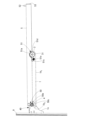
前記ハンガーブラケットと係合する固定部材を両端に有するバックバーと、後端部に前記バックバーと係合する第1係合部と前記後端部と先端部との間に設けられた前記ハンガーパイプと係合する第2係合部とを有するフェースアウトバーと、を有し、
前記バックバーの前記固定部材を前記ハンガーブラケットに係合させて前記バックバーを前記ハンガーブラケットの後端部側に取り付け、前記フェースアウトバーの前記第1係合部を前記バックバーに係合させ、前記第2係合部を前記ハンガーパイプに係合させて、前記フェースアウトバーが前記ハンガーパイプを跨いで、前記ハンガーパイプの前後に突き出るように設けられる。
前記バックバーは、円柱パイプからなり、
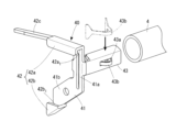
前記固定部材は、前記ハンガーブラケットの後端部の側面と当接する本体部と、前記本体部の上端及び下端に設けられた係合部と、前記本体部より直交する方向に延びて形成され,前記バックバーに挿入される挿入部とを有する。
前記係合部は、前記ハンガーブラケットの上辺と係合する上部係合部と下辺と係合する下部係合部とを有する。
前記上部係合部に、係止フック方向へさらに延びる上部係合片が設けられ、前記上部係合片は、前記ハンガーブラケットの上辺より下方向に位置するように形成されている。
前記フェースアウトバーは、円柱パイプからなり、
前記第1係合部は、前記バックバーの外周が嵌め込まれる円弧状のバックバー用受け部と前記フェースアウトバーに挿入される挿入部を有し、
前記第2係合部は、前記ハンガーパイプの外周が嵌まり込まれる円弧状のハンガーパイプ用受け部と前記フェースアウトバーに挿入される挿入部と、前記ハンガーパイプ用受け部の外周部に先端が当接するネジ部が設けられている。
前記第2係合部の前記ハンガーパイプ用受け部の中心と前記第1係合部の前記バックバー用受け部の中心までの距離は、前記バックバーの径方向の中心と前記ハンガーパイプの径方向の中心までの距離より大きく形成している。
1a :上辺
1b :下辺
1b1 :本体部
1b2 :後端部
1c :下辺
3 :ハンガーパイプ
4 :バックバー
5 :フェースアウトバー
8 :パイプ
9 :支柱
40 :固定部材
41 :本体部
41a :第1辺部
41b :第2辺部
42 :係合部
42a :上部係合部
42a1 :凹部
42b :下部係合部
42c :上部係合片
43 :挿入部
50 :第1係合部
50a :バックバー用受け部
51 :第2係合部
51a :ハンガーパイプ用受け部
Claims (5)
- 複数のスリットを有する支柱と、先端部にハンガーパイプが取り付けられるとともに後端部に前記スリットに挿入される係止フックとを有する板状のハンガーブラケットと、を備えるハンガーパイプ装置において、
前記ハンガーブラケットと係合する固定部材を両端に有するバックバーと、後端部に前記バックバーと係合する第1係合部と前記後端部と先端部との間に設けられた前記ハンガーパイプと係合する第2係合部とを有するフェースアウトバーと、を有し、
前記バックバーの前記固定部材を前記ハンガーブラケットに係合させて前記バックバーを前記ハンガーブラケットの後端部側に取り付け、前記フェースアウトバーの前記第1係合部を前記バックバーに係合させ、前記第2係合部を前記ハンガーパイプに係合させて、前記フェースアウトバーが前記ハンガーパイプを跨いで、前記ハンガーパイプの前後に突き出るように設けられる、
ハンガーパイプ装置。 - 前記バックバーの前記固定部材は、前記ハンガーブラケットの後端部の側面と当接する本体部と、前記本体部の上端に設けられ前記ハンガーブラケットの上辺が嵌め込まれる上部係合部と、前記本体部の下端に設けられ前記ハンガーブラケットの下辺が嵌め込まれる下部係合部と、前記本体部より直交する方向に延びて形成され,前記バックバーに挿入される挿入部とを有する、
請求項1に記載のハンガーパイプ装置。 - 前記上部係合部に、係止フック方向へさらに延びる上部係合片が設けられ、前記上部係合片は、前記ハンガーブラケットの上辺より下方向に位置するように形成されている、
請求項2に記載のハンガーパイプ装置。 - 前記バックバーと前記フェースアウトバーは、円柱パイプからなり、
前記第1係合部は、前記バックバーの外周が嵌め込まれる円弧状のバックバー用受け部と前記フェースアウトバーに挿入される挿入部を有し、
前記第2係合部は、前記ハンガーパイプの外周が嵌まり込まれる円弧状のハンガーパイプ用受け部と前記フェースアウトバーに挿入される挿入部と、前記ハンガーパイプ用受け部の外周部に先端が当接するネジ部が設けられている、
請求項1に記載のハンガーパイプ装置。 - 前記第2係合部の前記ハンガーパイプ用受け部の中心と前記第1係合部の前記バックバー用受け部の中心までの距離は、前記バックバーの径方向の中心と前記ハンガーパイプの径方向の中心までの距離より大きく形成している、
請求項4に記載のハンガーパイプ装置。
Priority Applications (1)
| Application Number | Priority Date | Filing Date | Title |
|---|---|---|---|
| JP2020136355A JP7536282B2 (ja) | 2020-08-12 | 2020-08-12 | ハンガーパイプ装置 |
Applications Claiming Priority (1)
| Application Number | Priority Date | Filing Date | Title |
|---|---|---|---|
| JP2020136355A JP7536282B2 (ja) | 2020-08-12 | 2020-08-12 | ハンガーパイプ装置 |
Publications (2)
| Publication Number | Publication Date |
|---|---|
| JP2022032509A JP2022032509A (ja) | 2022-02-25 |
| JP7536282B2 true JP7536282B2 (ja) | 2024-08-20 |
Family
ID=80350021
Family Applications (1)
| Application Number | Title | Priority Date | Filing Date |
|---|---|---|---|
| JP2020136355A Active JP7536282B2 (ja) | 2020-08-12 | 2020-08-12 | ハンガーパイプ装置 |
Country Status (1)
| Country | Link |
|---|---|
| JP (1) | JP7536282B2 (ja) |
Citations (2)
| Publication number | Priority date | Publication date | Assignee | Title |
|---|---|---|---|---|
| JP2000070091A (ja) | 1998-08-28 | 2000-03-07 | Sekisui Jushi Co Ltd | 商品陳列什器 |
| JP3167329U (ja) | 2011-02-04 | 2011-04-14 | 誠二郎 西井 | 陳列什器 |
Family Cites Families (3)
| Publication number | Priority date | Publication date | Assignee | Title |
|---|---|---|---|---|
| JPS62116958U (ja) * | 1986-01-14 | 1987-07-24 | ||
| JPH04105609A (ja) * | 1990-08-27 | 1992-04-07 | Higashinihonbashi Riyuutsuu Center:Kk | 衣類輸送用ハンガーラック |
| JPH0549530A (ja) * | 1991-08-27 | 1993-03-02 | Matsushita Electric Works Ltd | 陳列什器用オプシヨン |
-
2020
- 2020-08-12 JP JP2020136355A patent/JP7536282B2/ja active Active
Patent Citations (2)
| Publication number | Priority date | Publication date | Assignee | Title |
|---|---|---|---|---|
| JP2000070091A (ja) | 1998-08-28 | 2000-03-07 | Sekisui Jushi Co Ltd | 商品陳列什器 |
| JP3167329U (ja) | 2011-02-04 | 2011-04-14 | 誠二郎 西井 | 陳列什器 |
Also Published As
| Publication number | Publication date |
|---|---|
| JP2022032509A (ja) | 2022-02-25 |
Similar Documents
| Publication | Publication Date | Title |
|---|---|---|
| CA2084559C (en) | Pipe hanging clamp adapted for soldering | |
| US20070241238A1 (en) | Hanger | |
| WO2000013549A1 (en) | Hanger assembly | |
| US12022967B2 (en) | Plastic hook for paper hanger | |
| CN106104022A (zh) | 用于安装设备、特别是家用电器的固定系统 | |
| JP7536282B2 (ja) | ハンガーパイプ装置 | |
| US7441736B2 (en) | Bracket for retail store display systems | |
| US3481487A (en) | Display unit | |
| US4531697A (en) | Apparatus for aperture boards | |
| KR101765308B1 (ko) | 천장패널용 고정장치 | |
| JP4694912B2 (ja) | 長尺材の支持具 | |
| JP5027917B2 (ja) | 長尺材の支持具 | |
| CN119825994A (zh) | U型管束结构及其成型方法 | |
| KR200160979Y1 (ko) | 걸이구 | |
| JP7116990B2 (ja) | 掛け具 | |
| JP2002084616A (ja) | 中空壁用配線器具取付装置 | |
| US20200187372A1 (en) | Wall mount device | |
| KR200488682Y1 (ko) | 달력 고정 기구 | |
| JP3123047U (ja) | 架設受け具 | |
| JP6286086B2 (ja) | 配線・配管材支持具及び固定部材 | |
| JP4180419B2 (ja) | 天井吊金物 | |
| US12318027B2 (en) | Plastic hook for paper hanger | |
| JPH0435656Y2 (ja) | ||
| JP3240609U (ja) | 抜け止め部材 | |
| JP5095550B2 (ja) | クリップ |
Legal Events
| Date | Code | Title | Description |
|---|---|---|---|
| A80 | Written request to apply exceptions to lack of novelty of invention |
Free format text: JAPANESE INTERMEDIATE CODE: A80 Effective date: 20200831 |
|
| A621 | Written request for application examination |
Free format text: JAPANESE INTERMEDIATE CODE: A621 Effective date: 20230808 |
|
| A131 | Notification of reasons for refusal |
Free format text: JAPANESE INTERMEDIATE CODE: A131 Effective date: 20240220 |
|
| A521 | Request for written amendment filed |
Free format text: JAPANESE INTERMEDIATE CODE: A523 Effective date: 20240418 |
|
| TRDD | Decision of grant or rejection written | ||
| A01 | Written decision to grant a patent or to grant a registration (utility model) |
Free format text: JAPANESE INTERMEDIATE CODE: A01 Effective date: 20240723 |
|
| A61 | First payment of annual fees (during grant procedure) |
Free format text: JAPANESE INTERMEDIATE CODE: A61 Effective date: 20240731 |
|
| R150 | Certificate of patent or registration of utility model |
Ref document number: 7536282 Country of ref document: JP Free format text: JAPANESE INTERMEDIATE CODE: R150 |