JP7536282B2 - Hanger pipe device - Google Patents
Hanger pipe device Download PDFInfo
- Publication number
- JP7536282B2 JP7536282B2 JP2020136355A JP2020136355A JP7536282B2 JP 7536282 B2 JP7536282 B2 JP 7536282B2 JP 2020136355 A JP2020136355 A JP 2020136355A JP 2020136355 A JP2020136355 A JP 2020136355A JP 7536282 B2 JP7536282 B2 JP 7536282B2
- Authority
- JP
- Japan
- Prior art keywords
- hanger
- hanger pipe
- bar
- face
- back bar
- Prior art date
- Legal status (The legal status is an assumption and is not a legal conclusion. Google has not performed a legal analysis and makes no representation as to the accuracy of the status listed.)
- Active
Links
- 238000003780 insertion Methods 0.000 claims description 25
- 230000037431 insertion Effects 0.000 claims description 25
- 239000000463 material Substances 0.000 description 5
- 238000000034 method Methods 0.000 description 5
- 238000005452 bending Methods 0.000 description 3
- 230000002093 peripheral effect Effects 0.000 description 3
- 210000000078 claw Anatomy 0.000 description 2
- 239000002184 metal Substances 0.000 description 2
- 238000012986 modification Methods 0.000 description 1
- 230000004048 modification Effects 0.000 description 1
- 238000000465 moulding Methods 0.000 description 1
- 239000011347 resin Substances 0.000 description 1
- 229920005989 resin Polymers 0.000 description 1
Images


Landscapes
- Display Racks (AREA)
Description
特許法第30条第2項適用 カタログ配布 配布者 株式会社ロイヤル 配布日 令和1年11月14日Patent Law Article 30, Paragraph 2 applied Catalog distribution Distributor: Royal Co., Ltd. Distribution date: November 14, 2019
この発明は、ハンガーパイプ装置に関するものである。 This invention relates to a hanger pipe device.
衣料品を陳列や収納する時などに、ハンガーパイプ装置を用いることが多い。このハンガーパイプ装置としては、一対の支柱のそれぞれに設けられたスリットに、各ハンガーブラケットの係合フックを係合し、これらのハンガーブラケットの先端部にハンガーパイプが固定されたものが知られている。 Hanger pipe devices are often used when displaying or storing clothing. A known type of hanger pipe device has a pair of posts with slits in each of which the engaging hooks of the hanger brackets engage, and the hanger pipe is fixed to the tip of the hanger brackets.
また、上記したハンガーパイプの軸方向中央から前後に突き出るように、枝用のパイプ部材が固定され、このパイプ部材にハンガーを吊り下げるように構成されたハンガーパイプ装置も知られている(特許文献1参照)。 There is also a known hanger pipe device in which a branch pipe member is fixed to the hanger pipe so that it protrudes forward and backward from the axial center of the hanger pipe, and hangers are suspended from this pipe member (see Patent Document 1).
衣料品の陳列は、店舗のレイアウトなどにより様々な態様がある。例えば、ハンガーパイプの軸方向に複数のハンガーを吊り下げ、衣料品をハンガーの軸方向に直交するように陳列し、衣料品のサイド部分を見せるように陳列する、いわゆる、スリーブアウト方式の陳列方法、ハンガーパイプの軸方向中央から前後に突き出るように取り付けられたパイプ部材に複数のハンガーを吊り下げ、衣料品の正面方向を見せるように陳列する、いわゆるフェースアウト方式の陳列方法がある。 Clothing can be displayed in a variety of ways depending on the store layout. For example, there is the so-called sleeve-out display method, in which multiple hangers are hung in the axial direction of a hanger pipe, and the clothing is displayed perpendicular to the axial direction of the hangers, so that the sides of the clothing are visible, and the so-called face-out display method, in which multiple hangers are hung from a pipe member attached to the center of the axial direction of the hanger pipe so that they protrude forward and backward, so that the front of the clothing is visible.
ところで、店舗においては、スリーブアウト方式の陳列をフェースアウト方式の陳列に変更する場合がある。 Incidentally, in stores, sleeve-out displays are sometimes changed to face-out displays.
このような場合、従来は、スリーブアウト方式のハンガーパイプから前後に突き出るような枝用のパイプ部材を取り付けたフェースアウト方式のハンガーパイプに交換する必要がある。このため、店舗の陳列方法の変更が煩わしいという難点がある。 In such cases, it has traditionally been necessary to replace the sleeve-out hanger pipe with a face-out hanger pipe, which has branch pipe members that protrude from the front and back. This has the drawback of making it cumbersome to change the way the store displays its clothes.
また、ハンガーパイプの軸方向中央から前後に突き出るように取り付けられたパイプ部材を有するハンガーパイプ装置において、スリーブアウト方式の陳列を行う場合には、上記したパイプ部材が陳列の邪魔になるという難点があった。 In addition, in a hanger pipe device having a pipe member attached so as to protrude forward and backward from the axial center of the hanger pipe, when using the sleeve-out method of display, there is a drawback in that the pipe member gets in the way of the display.
この発明は、スリーブアウト方式とフェースアウト方式に商品陳列形態を容易に変更できるハンガーパイプ装置を提供することにある。 The aim of this invention is to provide a hanger pipe device that allows the product display format to be easily changed between sleeve-out and face-out formats.
この発明の一実施形態は、複数のスリットを有する支柱と、先端部にハンガーパイプが取り付けられるとともに後端部に前記スリットに挿入される係止フックとを有する板状のハンガーブラケットと、を備えるハンガーパイプ装置において、
前記ハンガーブラケットと係合する固定部材を両端に有するバックバーと、後端部に前記バックバーと係合する第1係合部と前記後端部と先端部との間に設けられた前記ハンガーパイプと係合する第2係合部とを有するフェースアウトバーと、を有し、
前記バックバーの前記固定部材を前記ハンガーブラケットに係合させて前記バックバーを前記ハンガーブラケットの後端部側に取り付け、前記フェースアウトバーの前記第1係合部を前記バックバーに係合させ、前記第2係合部を前記ハンガーパイプに係合させて、前記フェースアウトバーが前記ハンガーパイプを跨いで、前記ハンガーパイプの前後に突き出るように設けられる。
One embodiment of the present invention is a hanger pipe device including a post having a plurality of slits, and a plate -shaped hanger bracket having a hanger pipe attached to a tip end and a locking hook inserted into the slit at a rear end,
a back bar having fixing members at both ends that engage with the hanger bracket, and a face-out bar having a first engagement portion at a rear end that engages with the back bar and a second engagement portion provided between the rear end and a front end that engages with the hanger pipe,
The fixing member of the back bar is engaged with the hanger bracket to attach the back bar to the rear end side of the hanger bracket, the first engagement portion of the face-out bar is engaged with the back bar and the second engagement portion is engaged with the hanger pipe, and the face-out bar is arranged to straddle the hanger pipe and protrude in front and rear of the hanger pipe.
スリーブアウト方式のハンガーパイプ装置の前記ハンガーブラケットに、前記バックバーを取り付け、前記バックバーと前記ハンガーパイプを跨ぐように前記フェースアウトバーを取り付ける。これにより、スリーブアウト方式のハンガーパイプ装置からフェースアウト方式のハンガーパイプ装置に簡単に変更することができる。 The back bar is attached to the hanger bracket of the sleeve-out type hanger pipe device, and the face-out bar is attached so as to straddle the back bar and the hanger pipe. This makes it easy to change from a sleeve-out type hanger pipe device to a face-out type hanger pipe device.
他の観点によれば、この発明のハンガーパイプ装置は、以下の構成を含むことが好ましい。
前記バックバーは、円柱パイプからなり、
前記固定部材は、前記ハンガーブラケットの後端部の側面と当接する本体部と、前記本体部の上端及び下端に設けられた係合部と、前記本体部より直交する方向に延びて形成され,前記バックバーに挿入される挿入部とを有する。
From another point of view, the hanger pipe device of the present invention preferably includes the following configuration.
The back bar is made of a cylindrical pipe,
The fixing member has a main body portion that abuts against the side of the rear end of the hanger bracket, engagement portions provided on the upper and lower ends of the main body portion, and an insertion portion formed extending in a perpendicular direction from the main body portion and inserted into the back bar.
前記バックバーに前記挿入部を挿入することにより、前記固定部材が前記バックバーに取り付けられる。 The fixing member is attached to the back bar by inserting the insertion part into the back bar.
他の観点によれば、この発明のハンガーパイプ装置は、以下の構成を含むことが好ましい。
前記係合部は、前記ハンガーブラケットの上辺と係合する上部係合部と下辺と係合する下部係合部とを有する。
From another point of view, the hanger pipe device of the present invention preferably includes the following configuration.
The engaging portion has an upper engaging portion that engages with an upper side of the hanger bracket and a lower engaging portion that engages with a lower side of the hanger bracket.
前記上部係合部に前記ハンガーブラケットの上辺を嵌め込み、前記下部係合部に前記ハンガーブラケットの下辺を嵌め込むことで、前記固定部材は、前記ハンガーブラケットに係合し、前記バックバーが前記ハンガーブラケットの後端部側に固定される。 By fitting the upper edge of the hanger bracket into the upper engagement portion and the lower edge of the hanger bracket into the lower engagement portion, the fixing member engages with the hanger bracket and the back bar is fixed to the rear end side of the hanger bracket.
他の観点によれば、この発明のハンガーパイプ装置は、以下の構成を含むことが好ましい。
前記上部係合部に、係止フック方向へさらに延びる上部係合片が設けられ、前記上部係合片は、前記ハンガーブラケットの上辺より下方向に位置するように形成されている。
From another point of view, the hanger pipe device of the present invention preferably includes the following configuration.
The upper engagement portion is provided with an upper engagement piece that extends further toward the locking hook, and the upper engagement piece is formed so as to be positioned below the upper side of the hanger bracket.
前記固定部材を前記ハンガーブラケットに固定した際に、前記上部係合片は、前記ハンガーブラケットの上辺に当接して上方向へ変形する。このように、前記上部係合片が変形することにより、前記上部係合片は下方向へ付勢力が生じ、前記下部係合部との間で前記ハンガーブラケットを挟み込む力が加わることになり、前記固定部材がハンガーブラケット1に確実に固定される。
When the fixing member is fixed to the hanger bracket, the upper engagement piece abuts against the upper edge of the hanger bracket and deforms upward. In this way, the upper engagement piece is biased downward by the deformation of the upper engagement piece, and a force is applied between the upper engagement piece and the lower engagement part to clamp the hanger bracket, so that the fixing member is securely fixed to the
他の観点によれば、この発明のハンガーパイプ装置は、以下の構成を含むことが好ましい。
前記フェースアウトバーは、円柱パイプからなり、
前記第1係合部は、前記バックバーの外周が嵌め込まれる円弧状のバックバー用受け部と前記フェースアウトバーに挿入される挿入部を有し、
前記第2係合部は、前記ハンガーパイプの外周が嵌まり込まれる円弧状のハンガーパイプ用受け部と前記フェースアウトバーに挿入される挿入部と、前記ハンガーパイプ用受け部の外周部に先端が当接するネジ部が設けられている。
From another point of view, the hanger pipe device of the present invention preferably includes the following configuration.
The face-out bar is made of a cylindrical pipe,
The first engagement portion has an arc-shaped back bar receiving portion into which the outer periphery of the back bar is fitted and an insertion portion that is inserted into the face-out bar,
The second engagement portion includes an arc-shaped hanger pipe receiving portion into which the outer periphery of the hanger pipe is fitted, an insertion portion which is inserted into the face-out bar, and a screw portion whose tip abuts against the outer periphery of the hanger pipe receiving portion.
前記このネジ部を締めることで、ハンガーパイプ用受け部は、曲率が小さくなるように変形し、ハンガーパイプ用受け部に嵌め込まれた前記ハンガーパイプが受け部より外れないように構成されている。 By tightening the screw portion, the hanger pipe receiving portion is deformed so that the curvature becomes smaller, and the hanger pipe fitted into the hanger pipe receiving portion is configured not to come off the receiving portion.
他の観点によれば、この発明のハンガーパイプ装置は、以下の構成を含むことが好ましい。
前記第2係合部の前記ハンガーパイプ用受け部の中心と前記第1係合部の前記バックバー用受け部の中心までの距離は、前記バックバーの径方向の中心と前記ハンガーパイプの径方向の中心までの距離より大きく形成している。
From another point of view, the hanger pipe device of the present invention preferably includes the following configuration.
The distance between the center of the receiving portion for the hanger pipe of the second engagement part and the center of the receiving portion for the back bar of the first engagement part is greater than the distance between the radial center of the back bar and the radial center of the hanger pipe.
このように、前記第2係合部の前記ハンガーパイプ用受け部の中心と前記第1係合部の前記バックバー用受け部の中心までの距離をに大きく形成することにより、前記フェースアウトバーを前記バックバーと前記ハンガーパイプを跨ぐように、前記第1係合部と前記第2係合部を用いて取り付けると、前記バックバーを前記支柱側へ押し付けるように力が加わり、前記バックバーを前記ハンガーブラケット上に強固に固定することができる。 In this way, by making the distance between the center of the hanger pipe receiving portion of the second engagement portion and the center of the back bar receiving portion of the first engagement portion large, when the face-out bar is attached using the first engagement portion and the second engagement portion so as to straddle the back bar and the hanger pipe, a force is applied to press the back bar against the support pole, and the back bar can be firmly fixed onto the hanger bracket.
この発明は、スリーブアウト方式のハンガーパイプ装置の前記ハンガーブラケットに、前記バックバーを取り付け、前記バックバーと前記ハンガーパイプを跨ぐように前記フェースアウトバーを取り付けることにより、スリーブアウト方式のハンガーパイプ装置からフェースアウト方式のハンガーパイプ装置に簡単に変更することができるので、スリーブアウト方式からフェースアウト方式に商品陳列形態を容易に変更できる。 This invention allows the sleeve-out type hanger pipe device to be easily changed to a face-out type hanger pipe device by attaching the back bar to the hanger bracket of the sleeve-out type hanger pipe device and attaching the face-out bar so as to straddle the back bar and the hanger pipe, so that the product display format can be easily changed from the sleeve-out type to the face-out type.
この発明の実施の形態について図面を参照しながら詳細に説明する。なお、図中同一または相当部分には同一符号を付し、説明の重複を避けるためにその説明は繰返さない。 The embodiment of the present invention will be described in detail with reference to the drawings. Note that the same or corresponding parts in the drawings are given the same reference numerals, and their explanation will not be repeated to avoid duplication.
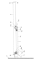
この発明のハンガーパイプ装置は、図1に示すように、壁等に固定される支柱9に複数のスリット91が設けられ、このスリット91にハンガーブラケット1の後端部に設けられた係止フック10(図4、図11参照)を差し込んで装着される。そして、ハンガーブラケット1の先端部にハンガーパイプ3が固定される。
As shown in Figure 1, the hanger pipe device of this invention has
ハンガーブラケット1は金属板製で形成され、図4に示すように、この実施形態においては、後端部の端辺13に上下一定間隔をおいて3段の逆L字形に垂れ下がる係止フック10が形成されている。この係止フック10の基端部には、支柱9のスリット91に嵌め込むための矩形状の切り込み11が設けられている。
The
図1及び図4に示すように、支柱9のスリット91に係止フック10が挿入され、係止フック10の基端部の切り込み11がスリット91の端部に嵌め込まれ、ハンガーブラケット1が支柱9に取り付けられる。スリット91に係止フック10を係止することにより、ハンガーブラケット1が支柱9に片持ち状に支持される。
As shown in Figures 1 and 4, the
図4に示すように、ハンガーブラケット1の上辺1aは、直線状に延び一番上の係止フック10の上辺と連なっている。下辺1bは、直線状の本体部1b1と本体部1b1から端辺13に向かって円弧状に拡がる後端部1b2とからなる。
As shown in Figure 4, the
後述するように、ハンガーブラケット1の上辺1aと下辺1bの後端部1b2の下辺1cとの間にバックバー4に取り付けられた固定部材40が係合し、ハンガーブラケット1にバックバー4が取り付けられる。
As described below, a fixing
この実施形態においては、ハンガーパイプ3の両端に雌ねじを設けた打ち込み用ナット部材31が圧入されている(図3参照)。ハンガーブラケット1の先端部とハンガーパイプ3の端部とを合わせ、ハンガーパイプ3に設けた孔(図示せず)に、ねじ32を通し、打ち込み用ナット部材31の雌ねじにねじ32をねじ込み、ハンガーブラケット1にハンガーパイプ3が固定される。
In this embodiment, a driving
ハンガーブラケット1とハンガーパイプ3は、ねじを用いた固定以外に種々の固定方法を用いることができる。例えば、先端部にハンガーパイプ3が挿入される開口部が設けられ、この開口部にパイプ用固定具を設けたハンガーブラケットを用い、ハンガーブラケットの開口部にパイプ8を挿入し、パイプ用固定具を用いてハンガーブラケットの開口部に挿入されたハンガーパイプを固定するようにしたハンガーパイプ装置がある。
The
上記したように、本実施形態のハンガーブラケット1は、後端部に支柱9(図1及び図4参照)のスリット91に対応した係止フック10が上下に一定間隔をおいて3か所に設けられた、いわゆる3爪のタイプである。なお、係止フック10が上下に一定間隔をおいて2か所に設けられた2爪のタイプ、係止フック10が1つの1爪のタイプなど、係止フック10を有するハンガーブラケット1にこの発明は適用することができる。
As described above, the
図1に示すように、バックバー4は、ハンガーブラケット1の後端部に係合する固定部材40が両端に取り付けられている。本実施形態においては、バックバー4は、ハンガーパイプ3より小径の円柱パイプで構成されている。バックバー4の両端に取り付けられた固定部材40をそれぞれハンガーブラケット1に係合させる。これにより、一対のハンガーブラケット1、1間の後端部側にバックバー4が取り付けられる。
As shown in FIG. 1, the
ハンガーブラケット1とバックバー4とを跨ぐようにフェースアウトバー5が取り付けられる。フェースアウトバー5は、後端部にバックバー4と係合する第1係合部50と後端部と先端部との間に設けられたハンガーパイプ3と係合する第2係合部51を有する。フェースアウトバー5の第1係合部50をバックバー4に係合させ、第2係合部51をハンガーパイプ3に係合させて、バックバー4とハンガーパイプ3を跨ぐようにフェースアウトバー5が取り付けられる。
The face-out
なお、本実施形態においては、図2及び図3に示すように、フェースアウトバー5の径方向の半分の高さまでハンガーパイプ3に嵌まり込み、支柱9に対して略直交若しくは先端側が少し上がった状態でバックバー4とハンガーパイプ3を跨ぐようにフェースアウトバー5が取り付けられる。このため、フェースアウトバー5に設けられる第1係合部50及び第2係合部51は、支柱9に対して略直交若しくは先端側が少し上がった状態でバックバー4とハンガーパイプ3を跨ぐように、それぞれのパイプに嵌め込まれるように寸法が規定されている。
In this embodiment, as shown in Figures 2 and 3, the face-out
フェースアウトバー5は、本実施形態においては、円柱パイプで構成され、先端部近傍に上向きに突設されたピン52が設けられ、先端部にはエンドキャップ53が取り付けられている。
In this embodiment, the face-out
第1係合部50と第2係合部51を用いて、バックバー4とハンガーパイプ3を跨ぐようにフェースアウトバー5を取り付ける。これにより、フェースアウトバー5は、ハンガーパイプ3に対して直交して、ハンガーパイプ3の前後に突き出るように設けられることになる。このように、スリーブアウト方式のハンガーパイプ装置に、バックバー4とフェースアウトバー5を取り付けることにより、フェースアウト方式のハンガーパイプ装置に変更することができる。
The face-out
また、バックバー4とハンガーパイプ3とにフェースアウトバー5の第1係合部50と第2係合部51が係合している。フェースアウトバー5は、ハンガーパイプ3だけでなくバックバー4にも係合しているので、フェースアウトバー5の先端側に下方向の力が加わってもバックバー4によりフェースアウトバー5の回転することが防止できる。バークバー4は、フェースアウトバー5の固定と回転を防止している。
The
次に、このハンガーパイプ装置につき,図面を参照してさらに説明する。まず、バックバー4について図5及び図7を参照して説明する。
Next, this hanger pipe device will be further explained with reference to the drawings. First, the
図5に示すように、バックバー4は、ハンガーブラケット1の後端部に装着される固定部材40が両端に取り付けられている。固定部材40は、左右対称に形成されているので、一方の固定部材40について説明する。本実施形態では、バックバー4の左端部に取り付けられる固定部材40について図面を参照して説明する。
As shown in FIG. 5, the
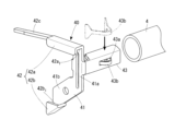
本実施形態においては、バックバー4は、中空パイプとしてのる円柱パイプで構成されている。固定部材40は、ハンガーブラケット1の後端部1b2の側面と当接する本体部41と、本体部41の上端及び下端に設けられた係合部42と、本体部41より直交する方向に延びて形成された挿入部43とを有する(図6及び図7参照)。固定部材40は、金属板材を折曲加工により形成されている。
In this embodiment, the
本体部41は、上下方向に延びる第1辺部41aと第1辺部41aから斜め下方向に延びる第2辺部41bとを有し、ハンガーブラケット1の後端部1b2の側面と部分的に重なり合うように形成されている。
The
係合部42は、ハンガーブラケット1の上辺1aと係合する上部係合部42aと下辺1cと係合する下部係合部42bとを有する(図5参照)。上部係合部42aは、第1辺部41aの上端からハンガーブラケット1の係止フック10方向へ延び逆L字型に垂れ下がるように形成されている。この逆L字型の凹部42a1にハンガーブラケット1の上辺1aが嵌め込まれる。
The engaging
下部係合部42bは、第2辺部41bの下端から斜め上方向にL字型に立ち上がるように形成されている。L字型の凹部42b1にハンガーブラケット1の下辺1cが嵌め込まれる。
The
上部係合部42aには、係止フック10方向へさらに延びる上部係合片42cが設けられている。この上部係合片42cは、ハンガーブラケット1の上辺1aより下方向に位置するように形成されている。ハンガーブラケット1の後端部側の上辺1aと下辺1cを上部係合部42aと下部係合部42bを嵌め込むことにより、固定部材40は、ハンガーブラケット1に係合し、バックバー4がハンガーブラケット1の後端部側に固定される。
The
この時、上部係合片42cは、図6の1点鎖線で示すように、ハンガーブラケット1の上辺1aに当接して上方向へ変形する。このように、上部係合片42cが変形することにより、上部係合片42cは下方向へ付勢力が生じ、下部係合部42bとの間でハンガーブラケット1を挟み込む力が加わることになり、固定部材40がハンガーブラケット1に確実に固定される。
At this time, the
固定部材40に設けられた挿入部43は、バックバー4のパイプの内周に挿入され、固定部材40がバックバー4に取り付けられる。
The
図7に示すように、挿入部43は、内部に4角形の空間を有する矩形状に形成されている。挿入部43の内部に、挿入部43をパイプ内周面に押圧するための板ばね材43bが取り付けられる。挿入部43に設けた矩形孔43aから板ばね材43bが突出するように、挿入部43の内部に板ばね材43bが配設される。
As shown in FIG. 7, the
挿入部43をバックバー4の端部からパイプの内周に差し込むと、板ばね材43bが挿入部43に押し込まれる。そして、板ばね材43bの押圧力により、挿入部43がバックバー4のパイプ内周面に押し付けられて固定される。これにより、バックバー4に固定部材40が脱落することなく取り付けられる。
When the
図5に示すように、バックバー4の両端に固定部材40が取り付けられる。図13に示すように、ハンガーブラケット1の後端部1b2にバックバー4に取り付けられた固定部材40の係合部42係合させることにより、ハンガーブラケット1の後端部側にバックバー4が取り付けられる。
As shown in Fig. 5, fixing
次に、フェースアウトバー5について、図2,図3、図8、図9、図10及び図11を参照して説明する。
Next, the face out
フェースアウトバー5は,本実施形態においては、中空パイプとしての円柱パイプで構成され、後端部に第1係合部50が嵌め込まれ、フェースアウトバー5の中間部に第2係合部51が嵌め込まれ、フェースアウトバー5に第1係合部50及び第2係合部51が設けられる。第1係合部50と第2係合部51は、樹脂成形により形成される。
In this embodiment, the face-out
図3及び図9に示すように、第1係合部50は、バックバー4の外周が嵌め込まれる円弧状のバックバー用受け部50aとフェースアウトバー5に挿入される挿入部50bを有する。挿入部50bの外径はフェースアウトバー5の内周に合わせて形成され、挿入部50bはフェースアウトバー5に圧入される。
As shown in Figures 3 and 9, the
バックバー用受け部50aは、バックバー4に対してフェースアウトバー5が直交方向に取り付けられるように、フェースアウトバー5の軸線方向と直交する方向にバックバー4の外周形状に倣って円弧状の溝部が所定の長さを有して形成されている。
The back
フェースアウトバー5の後端部は、第1係合部50の回り止め用の切り欠き54とこの切り欠き54の軸線上に切り欠き54から離れた位置に係合孔55が設けられている。
The rear end of the face-out
第1係合部50の挿入部50bは、切り欠き54に嵌まり込む突出片50cと、径方向に撓むように構成された舌片50dと、舌片50dに設けられた突起50eとを有する。突出片50cと突起50eは、バックバー用受け部50aの中央部分の軸線上に配置されている。
The
フェースアウトバー5の切り欠き54と第1係合部50の突出片50cを合わせて、挿入部50bをフェースアウトバー5の内面に挿入して圧入させる。この挿入部50bの挿入により、突出片50cは切り欠き54に沿ってフェースアウトバー5の先端方向に移動する。舌片50dも撓みながら移動する。舌片50dの突起50eが係合孔55に臨む位置まで移動すると、舌片の50cの撓みが復帰し、係合孔55と突起50eが係合し、フェースアウトバー5の後端部に第1係合部50が取り付けられる。
The
フェースアウトバー5の後端部と先端部との間、本実施形態においては、中間部に第2係合部51を嵌め込むための孔部56が設けられている。本実施形態においては、図2及び図3に示すように、フェースアウトバー5の径方向の半分の高さまでハンガーパイプ3に嵌まり込むように構成されているので、この孔部56は、フェースアウトバー5の径方向の半分の高さより第2係合部51のハンガーパイプ用受け部51aの厚み分大きく切り欠かれている。
Between the rear end and the front end of the face-out
この孔部56から後端方向へ切り欠き57が連なって設けられている。さらに、孔部56の切り欠き57と対向する位置には、第2係合部51の固定用切り欠き58が設けられている。この切り欠き57、58と後端部に設けられた切り欠き54は、フェースアウトバー5の同軸上に配置され、第1係合部50と第2係合部51とのフェースアウトバー5に対する取り付け角度が同じになるように構成している。
第2係合部51は、ハンガーパイプ3の外周が嵌まり込まれる円弧状のハンガーパイプ用受け部51aとフェースアウトバー5に挿入される挿入部51bを有する。挿入部51bは、切り欠き57の幅と同じ幅を有し、長さは切り欠き57の端部から切り欠き57に対向する孔部56の端部までである。挿入部51bの端部には爪部51c,51dが設けられている。
The
第2係合部51は、ハンガーパイプ用受け部51aの外周部に先端が当接するネジ部51eが設けられ、このネジ部51eを締めることで、ハンガーパイプ用受け部51aは、曲率が小さくなるように変形し、ハンガーパイプ用受け部51aに嵌め込まれたハンガーパイプ3がハンガーパイプ用受け部51aより外れないように構成されている。
The
ハンガーパイプ用受け部51aは、ハンガーパイプ3に対してフェースアウトバー5が直交方向に取り付けられるように、ハンガーパイプ3の軸線方向と直交する方向にハンガーパイプ3の外周形状に倣って円弧状の溝部が所定の長さを有して形成されている。前述したように、ネジ部51eを締め付けることにより、ハンガーパイプ用受け部51aの曲率は小さくなる。このため、ハンガーパイプ3に嵌め込む際には、ネジ部51eを緩めておき、ハンガーパイプ3に嵌め込みやすくする。
The hanger
フェースアウトバー5の孔部56と切り欠き57、58に合わせて挿入部51bを嵌め込み、爪部51c、51dを切り欠き57、58のエッジに嵌め込み、フェースアウトバー5の中間部に第2係合部51が固定される。
The
第2係合部51のハンガーパイプ用受け部51aの中心と第1係合部50のバックバー用受け部50aの中心までの距離B(図8参照)は、バックバー4の径方向の中心とハンガーパイプ3の径方向の中心までの距離C(図13参照)より僅かに大きく形成している。このように、距離Bを僅かに大きく形成することにより、フェースアウトバー5をバックバー4とハンガーパイプ3を跨ぐように、第1係合部50と第2係合部51を用いて取り付けると、バックバー4を支柱9側へ押し付けるように力が加わり、バックバー4をハンガーブラケット1上に強固に固定することができる。
The distance B (see FIG. 8) between the center of the hanger
また、本実施形態においては、第2係合部51のハンガーパイプ用受け部51aの中心とフェースアウトバー5の先端までの距離A(図8参照)と第1係合部50のバックバー用受け部50aの中心までの距離Bとは,同じ距離に形成している。これにより、ハンガーパイプ3の前後に延びるフェースアウトバー5の長さが等しくなる。
In addition, in this embodiment, the distance A (see FIG. 8) between the center of the hanger
なお、本実施形態においては、図2及び図3に示すように、フェースアウトバー5の径方向の半分の高さまでハンガーパイプ3に嵌まり込み、支柱9に対して略直交若しくは先端側が少し上がった状態でバックバー4とハンガーパイプ3を跨ぐようにフェースアウトバー5が取り付けられる。このため、フェースアウトバー5に設けられる第1係合部50のバックバー用受け部50a及び第2係合部51のハンガーパイプ用受け部51aは、それぞれのパイプに嵌め込まれ位置を規定して形成されている。
In this embodiment, as shown in Figures 2 and 3, the face-out
次に、この実施形態のハンガーパイプ装置の組み立て手順について図11~図14を参照して説明する。 Next, the assembly procedure for the hanger pipe device of this embodiment will be described with reference to Figures 11 to 14.
図11及び図12に示すように、ハンガーブラケット1の先端部とハンガーパイプ3の端部とを合わせ、ハンガーパイプ3に設けた孔(図示せず)に、ねじ32を通し、打ち込み用ナット部材31の雌ねじにねじ32をねじ込み、ハンガーブラケット1にハンガーパイプ3を固定する。
As shown in Figures 11 and 12, the tip of the
支柱9のスリット91にハンガーブラケット1の係止フック10を挿入し、係止フック10の基端部の切り込み11をスリット91の端部にはめ込み、ハンガーブラケット1を支柱9に取り付ける。スリット91に係止フック10を係止することにより、ハンガーブラケット1が支柱9に片持ち状に支持される。ハンガーブラケット1の先端には、ハンガーパイプ3が取り付けられている。
The locking
続いて、図13に示すように、両端に固定部材40を取り付けたバックバー4をハンガーブラケット1の中央付近に配置し、固定部材40の上部係合部42aとハンガーブラケット1の上辺1aとを係合させる。この状態でバックバー4を支柱9側へスライドさせ、スリット91に上部係合片42cの先端が入り込む位置まで移動させる。
Next, as shown in FIG. 13, the
バックバー4の移動により、ハンガーブラケット1の後端部側の上辺1aと下辺1cを上部係合部42aと下部係合部42bが嵌め込まれ、固定部材40は、ハンガーブラケット1と係合し、バックバー4がハンガーブラケット1の後端部側に固定される。
By moving the
その後、図14に示すように、フェースアウトバー5の第1係合部50のバックバー用受け部50aとバックバー4とを嵌め込み、フェースアウトバー5を下方向に回転させ、第2係合部51のハンガーパイプ用受け部51aに嵌め込む。フェースアウトバー5をバックバー4とハンガーパイプ3を跨ぐように、第1係合部50と第2係合部51を用いて取り付けると、バックバー4を支柱9側へ押し付けるように力が加わり、バックバー4をハンガーブラケット1上に強固に固定することができる。
Then, as shown in FIG. 14, the
このネジ部51eを締めて、ハンガーパイプ用受け部51aに嵌め込まれたハンガーパイプ3を固定する。このようにして、図1に示すハンガーパイプ装置が得られる。
The
フェースアウトバー5は,第1係合部50と第2係合部51をバックバー4とハンガーパイプ3に係合させるだけで取り付けることができる。フェースアウトバー5の係合位置はハンガーブラケット1、1間であればどこでもよく、フェースアウトバー5を設けるレイアウト位置を自由に選択することができる。
The face-out
また、フェースアウト方式のレイアウトからスリーブアウト方式に変更する場合には、ネジ部51eを緩め、フェースアウトバー5を取り外すことで対応することができる。
In addition, if you want to change from a face-out layout to a sleeve-out layout, you can do so by loosening the
フェースアウトバー5は、ブラケット1、1間であれば複数本取り付けてもよい。図15に示すように、2本のフェースアウトバー5を設けたハンガーパイプ装置を容易に構成することができる。
Multiple face-out
上記した実施形態においては、ハンガーパイプ3と、バックバー4と、フェースアウトバー5は、円柱パイプで構成しているが、角柱パイプなどで構成したハンガーパイプ装置にもこの発明は適用することができる。
In the above embodiment, the
今回開示された実施の形態はすべての点で例示であって制限的なものではないと考えられるべきである。この発明の範囲は、上記した実施の形態の説明ではなくて特許請求の範囲によって示され、特許請求の範囲と均等の意味および範囲内でのすべての変更が含まれることが意図される。 The embodiments disclosed herein should be considered to be illustrative and not restrictive in all respects. The scope of the present invention is indicated by the claims, not by the description of the embodiments above, and is intended to include all modifications within the meaning and scope of the claims.
1 :ハンガーブラケット
1a :上辺
1b :下辺
1b1 :本体部
1b2 :後端部
1c :下辺
3 :ハンガーパイプ
4 :バックバー
5 :フェースアウトバー
8 :パイプ
9 :支柱
40 :固定部材
41 :本体部
41a :第1辺部
41b :第2辺部
42 :係合部
42a :上部係合部
42a1 :凹部
42b :下部係合部
42c :上部係合片
43 :挿入部
50 :第1係合部
50a :バックバー用受け部
51 :第2係合部
51a :ハンガーパイプ用受け部
1:
Claims (5)
前記ハンガーブラケットと係合する固定部材を両端に有するバックバーと、後端部に前記バックバーと係合する第1係合部と前記後端部と先端部との間に設けられた前記ハンガーパイプと係合する第2係合部とを有するフェースアウトバーと、を有し、
前記バックバーの前記固定部材を前記ハンガーブラケットに係合させて前記バックバーを前記ハンガーブラケットの後端部側に取り付け、前記フェースアウトバーの前記第1係合部を前記バックバーに係合させ、前記第2係合部を前記ハンガーパイプに係合させて、前記フェースアウトバーが前記ハンガーパイプを跨いで、前記ハンガーパイプの前後に突き出るように設けられる、
ハンガーパイプ装置。 A hanger pipe device comprising a support pole having a plurality of slits, and a plate-shaped hanger bracket having a hanger pipe attached to a tip end thereof and a locking hook inserted into the slits at a rear end thereof,
a back bar having fixing members at both ends that engage with the hanger bracket, and a face-out bar having a first engagement portion at a rear end that engages with the back bar and a second engagement portion provided between the rear end and a front end that engages with the hanger pipe,
The fixing member of the back bar is engaged with the hanger bracket to attach the back bar to the rear end side of the hanger bracket, the first engagement portion of the face-out bar is engaged with the back bar, and the second engagement portion is engaged with the hanger pipe, so that the face-out bar straddles the hanger pipe and protrudes from the front and rear of the hanger pipe.
Hanger pipe device.
請求項1に記載のハンガーパイプ装置。 The fixing member of the back bar has a main body portion that abuts against the side surface of the rear end portion of the hanger bracket, an upper engagement portion provided at the upper end of the main body portion and into which the upper edge of the hanger bracket is fitted, a lower engagement portion provided at the lower end of the main body portion and into which the lower edge of the hanger bracket is fitted, and an insertion portion that is formed extending in a direction perpendicular to the main body portion and is inserted into the back bar.
2. The hanger pipe device according to claim 1.
請求項2に記載のハンガーパイプ装置。 The upper engagement portion is provided with an upper engagement piece that extends further toward the locking hook, and the upper engagement piece is formed so as to be positioned below the upper side of the hanger bracket.
3. The hanger pipe device according to claim 2 .
前記第1係合部は、前記バックバーの外周が嵌め込まれる円弧状のバックバー用受け部と前記フェースアウトバーに挿入される挿入部を有し、
前記第2係合部は、前記ハンガーパイプの外周が嵌まり込まれる円弧状のハンガーパイプ用受け部と前記フェースアウトバーに挿入される挿入部と、前記ハンガーパイプ用受け部の外周部に先端が当接するネジ部が設けられている、
請求項1に記載のハンガーパイプ装置。 The back bar and the face-out bar are made of cylindrical pipes,
The first engagement portion has an arc-shaped back bar receiving portion into which the outer periphery of the back bar is fitted and an insertion portion that is inserted into the face-out bar,
The second engagement portion includes an arc-shaped hanger pipe receiving portion into which the outer periphery of the hanger pipe is fitted, an insertion portion that is inserted into the face-out bar, and a screw portion whose tip abuts against the outer periphery of the hanger pipe receiving portion.
2. The hanger pipe device according to claim 1.
請求項4に記載のハンガーパイプ装置。 The distance between the center of the hanger pipe receiving portion of the second engagement portion and the center of the back bar receiving portion of the first engagement portion is greater than the distance between the radial center of the back bar and the radial center of the hanger pipe.
5. The hanger pipe device according to claim 4 .
Priority Applications (1)
| Application Number | Priority Date | Filing Date | Title |
|---|---|---|---|
| JP2020136355A JP7536282B2 (en) | 2020-08-12 | 2020-08-12 | Hanger pipe device |
Applications Claiming Priority (1)
| Application Number | Priority Date | Filing Date | Title |
|---|---|---|---|
| JP2020136355A JP7536282B2 (en) | 2020-08-12 | 2020-08-12 | Hanger pipe device |
Publications (2)
| Publication Number | Publication Date |
|---|---|
| JP2022032509A JP2022032509A (en) | 2022-02-25 |
| JP7536282B2 true JP7536282B2 (en) | 2024-08-20 |
Family
ID=80350021
Family Applications (1)
| Application Number | Title | Priority Date | Filing Date |
|---|---|---|---|
| JP2020136355A Active JP7536282B2 (en) | 2020-08-12 | 2020-08-12 | Hanger pipe device |
Country Status (1)
| Country | Link |
|---|---|
| JP (1) | JP7536282B2 (en) |
Citations (2)
| Publication number | Priority date | Publication date | Assignee | Title |
|---|---|---|---|---|
| JP2000070091A (en) | 1998-08-28 | 2000-03-07 | Sekisui Jushi Co Ltd | Article display utensil |
| JP3167329U (en) | 2011-02-04 | 2011-04-14 | 誠二郎 西井 | Display fixtures |
Family Cites Families (3)
| Publication number | Priority date | Publication date | Assignee | Title |
|---|---|---|---|---|
| JPS62116958U (en) * | 1986-01-14 | 1987-07-24 | ||
| JPH04105609A (en) * | 1990-08-27 | 1992-04-07 | Higashinihonbashi Riyuutsuu Center:Kk | Hanger rack transporting clothing |
| JPH0549530A (en) * | 1991-08-27 | 1993-03-02 | Matsushita Electric Works Ltd | Attachment of display device |
-
2020
- 2020-08-12 JP JP2020136355A patent/JP7536282B2/en active Active
Patent Citations (2)
| Publication number | Priority date | Publication date | Assignee | Title |
|---|---|---|---|---|
| JP2000070091A (en) | 1998-08-28 | 2000-03-07 | Sekisui Jushi Co Ltd | Article display utensil |
| JP3167329U (en) | 2011-02-04 | 2011-04-14 | 誠二郎 西井 | Display fixtures |
Also Published As
| Publication number | Publication date |
|---|---|
| JP2022032509A (en) | 2022-02-25 |
Similar Documents
| Publication | Publication Date | Title |
|---|---|---|
| CA2084559C (en) | Pipe hanging clamp adapted for soldering | |
| US20070241238A1 (en) | Hanger | |
| WO2000013549A1 (en) | Hanger assembly | |
| US12022967B2 (en) | Plastic hook for paper hanger | |
| CN106104022A (en) | For installing the fixed system of equipment, particularly household electrical appliance | |
| JP7536282B2 (en) | Hanger pipe device | |
| US7441736B2 (en) | Bracket for retail store display systems | |
| US3481487A (en) | Display unit | |
| US4531697A (en) | Apparatus for aperture boards | |
| KR101765308B1 (en) | Fixing device for ceiling panel | |
| JP4694912B2 (en) | Long material support | |
| JP5027917B2 (en) | Long material support | |
| CN119825994A (en) | U-shaped tube bundle structure and forming method thereof | |
| KR200160979Y1 (en) | Hanger | |
| JP7116990B2 (en) | hanger | |
| JP2002084616A (en) | Wiring fixture mounting equipment for hollow walls | |
| US20200187372A1 (en) | Wall mount device | |
| KR200488682Y1 (en) | A calendar holder | |
| JP3123047U (en) | Mounting bracket | |
| JP6286086B2 (en) | Wiring / pipe material support and fixing member | |
| JP4180419B2 (en) | Ceiling hanger | |
| US12318027B2 (en) | Plastic hook for paper hanger | |
| JPH0435656Y2 (en) | ||
| JP3240609U (en) | Retaining material | |
| JP5095550B2 (en) | clip |
Legal Events
| Date | Code | Title | Description |
|---|---|---|---|
| A80 | Written request to apply exceptions to lack of novelty of invention |
Free format text: JAPANESE INTERMEDIATE CODE: A80 Effective date: 20200831 |
|
| A621 | Written request for application examination |
Free format text: JAPANESE INTERMEDIATE CODE: A621 Effective date: 20230808 |
|
| A131 | Notification of reasons for refusal |
Free format text: JAPANESE INTERMEDIATE CODE: A131 Effective date: 20240220 |
|
| A521 | Request for written amendment filed |
Free format text: JAPANESE INTERMEDIATE CODE: A523 Effective date: 20240418 |
|
| TRDD | Decision of grant or rejection written | ||
| A01 | Written decision to grant a patent or to grant a registration (utility model) |
Free format text: JAPANESE INTERMEDIATE CODE: A01 Effective date: 20240723 |
|
| A61 | First payment of annual fees (during grant procedure) |
Free format text: JAPANESE INTERMEDIATE CODE: A61 Effective date: 20240731 |
|
| R150 | Certificate of patent or registration of utility model |
Ref document number: 7536282 Country of ref document: JP Free format text: JAPANESE INTERMEDIATE CODE: R150 |