JP7536112B2 - Image processing device, mounting device, mounting system, image processing method, and mounting method - Google Patents
Image processing device, mounting device, mounting system, image processing method, and mounting method Download PDFInfo
- Publication number
- JP7536112B2 JP7536112B2 JP2022563504A JP2022563504A JP7536112B2 JP 7536112 B2 JP7536112 B2 JP 7536112B2 JP 2022563504 A JP2022563504 A JP 2022563504A JP 2022563504 A JP2022563504 A JP 2022563504A JP 7536112 B2 JP7536112 B2 JP 7536112B2
- Authority
- JP
- Japan
- Prior art keywords
- component
- mounting
- main body
- protrusion
- image
- Prior art date
- Legal status (The legal status is an assumption and is not a legal conclusion. Google has not performed a legal analysis and makes no representation as to the accuracy of the status listed.)
- Active
Links
Images


Classifications
-
- H—ELECTRICITY
- H05—ELECTRIC TECHNIQUES NOT OTHERWISE PROVIDED FOR
- H05K—PRINTED CIRCUITS; CASINGS OR CONSTRUCTIONAL DETAILS OF ELECTRIC APPARATUS; MANUFACTURE OF ASSEMBLAGES OF ELECTRICAL COMPONENTS
- H05K13/00—Apparatus or processes specially adapted for manufacturing or adjusting assemblages of electric components
- H05K13/08—Monitoring manufacture of assemblages
- H05K13/081—Integration of optical monitoring devices in assembly lines; Processes using optical monitoring devices specially adapted for controlling devices or machines in assembly lines
- H05K13/0813—Controlling of single components prior to mounting, e.g. orientation, component geometry
-
- H—ELECTRICITY
- H05—ELECTRIC TECHNIQUES NOT OTHERWISE PROVIDED FOR
- H05K—PRINTED CIRCUITS; CASINGS OR CONSTRUCTIONAL DETAILS OF ELECTRIC APPARATUS; MANUFACTURE OF ASSEMBLAGES OF ELECTRICAL COMPONENTS
- H05K13/00—Apparatus or processes specially adapted for manufacturing or adjusting assemblages of electric components
- H05K13/08—Monitoring manufacture of assemblages
- H05K13/081—Integration of optical monitoring devices in assembly lines; Processes using optical monitoring devices specially adapted for controlling devices or machines in assembly lines
- H05K13/0812—Integration of optical monitoring devices in assembly lines; Processes using optical monitoring devices specially adapted for controlling devices or machines in assembly lines the monitoring devices being integrated in the mounting machine, e.g. for monitoring components, leads, component placement
Landscapes
- Engineering & Computer Science (AREA)
- Operations Research (AREA)
- Manufacturing & Machinery (AREA)
- Microelectronics & Electronic Packaging (AREA)
- Supply And Installment Of Electrical Components (AREA)
- Manipulator (AREA)
Description
本明細書では、画像処理装置、実装装置、実装システム、画像処理方法及び実装方法を開示する。 This specification discloses an image processing device, an implementation device, an implementation system, an image processing method, and an implementation method.
従来、実装装置としては、吸着ノズルで吸着された電子部品の像を反射ミラーによってカメラに導き、カメラで撮像するものが提案されている(例えば、特許文献1など参照)。この装置では、装着ヘッドと装置の小型化とコストダウン、及び生産のタクトタイムの短縮が図れる構成を提供することができるとしている。Conventionally, a mounting device has been proposed that uses a reflecting mirror to guide the image of an electronic component picked up by a suction nozzle to a camera, which then captures the image (see, for example, Patent Document 1). This device is said to be capable of providing a configuration that allows for the miniaturization and cost reduction of the mounting head and device, as well as the shortening of production takt time.
しかしながら、上述した特許文献1では、本体からリードが突出された部品を採取し、基板上に形成された穴部にこのリードを挿入させて実装する処理については考慮されていなかった。このように、本体と本体から突出した突出部とを有する部品をより適正に認識し、基板などの処理対象物へより適正に配置することが求められていた。However, the above-mentioned
本開示は、このような課題に鑑みなされたものであり、本体から突出した突出部を有する部品を実装するに際して、より簡便な構成でより確実に実装処理を実行することができる画像処理装置、実装装置、実装システム、画像処理方法及び実装方法を提供することを主目的とする。The present disclosure has been made in consideration of such problems, and has as its primary objective the provision of an image processing device, mounting device, mounting system, image processing method, and mounting method that can perform mounting processing more reliably with a simpler configuration when mounting components having protrusions that protrude from the main body.
本開示では、上述の主目的を達成するために以下の手段を採った。 In this disclosure, the following measures have been taken to achieve the above-mentioned primary objective.
本開示の画像処理装置は、
本体と前記本体に形成された1以上の突出部とを有する部品の該突出部を処理対象物に形成された挿入部に挿入して前記部品を前記処理対象物に配置する実装部を備えた実装装置に用いられる画像処理装置であって、
前記部品に対して側方から光を照射する側射照明と前記部品に対して下方から光を照射する落射照明とを点灯可能な照明部と、前記本体と前記突出部との距離の被写界深度を少なくとも有し前記部品を下方から撮像する撮像部と、を有する撮像ユニットの前記側射照明及び/又は前記落射照明で撮像した撮像画像を取得し、取得した前記撮像画像から前記本体の形状と前記突出部の位置と前記突出部の数と前記突出部の先端部とを検出し、前記挿入部の情報を取得し、前記本体の形状及び方向を含む輪郭形状モデルと前記突出部の位置、数、先端部の特徴を含む突出部モデルとを含む部品モデルを生成する画像制御部、
を備えたものである。
The image processing device of the present disclosure includes:
1. An image processing device used in a mounting device including a mounting unit that inserts a protrusion of a component having a main body and one or more protrusions formed on the main body into an insertion portion formed on a processing object, and places the component on the processing object,
an image control unit that acquires captured images captured by the side illumination and/or the epi-illumination of an imaging unit having an illumination unit capable of turning on a side illumination that irradiates light to the component from the side and an epi-illumination that irradiates light to the component from below, the image capture unit having a depth of field of at least the distance between the main body and the protrusions and capturing an image of the component from below, detects the shape of the main body, the positions of the protrusions, the number of the protrusions, and the tips of the protrusions from the acquired captured images, acquires information about the insertion portion, and generates a component model including a contour shape model including the shape and direction of the main body and a protrusion model including the positions, number, and features of the tips of the protrusions;
It is equipped with the following:
この画像処理装置では、部品に対して側方から光を照射する側射照明及び部品に対して下方から光を照射する落射照明の少なくとも一方で撮像した撮像画像から本体の形状と突出部の位置と突出部の数と突出部の先端部とを検出し、挿入部の情報を取得し、本体の形状及び方向を含む輪郭形状モデルと突出部の位置、数、先端部の特徴を含む突出部モデルとを含む部品モデルを生成する。この画像処理装置では、例えば、突出部の先端部にレーザを照射してこの先端部に焦点を合わせて撮像するような特別な照明部や撮像部を要することなく、側方からの側射照明と下方からの落射照明とによって突出部や本体をより確実に検出可能な撮像画像を得ることができる。この画像処理装置では、このように得られた撮像画像を用いて部品の基準データとなる部品モデルを構築することができる。そして、実装装置は、この部品モデルを用いて突出部を有する部品の認識を実行し、実装処理を実行することができる。したがって、この画像処理装置では、本体から突出した突出部を有する部品を実装するに際して、より簡便な構成でより確実に実装処理を実行することができる。In this image processing device, the shape of the main body, the position of the protrusions, the number of protrusions, and the tip of the protrusions are detected from an image captured by at least one of side lighting, which irradiates the part from the side, and epi-illumination, which irradiates the part from below, and information on the insertion part is obtained, and a part model is generated that includes a contour shape model including the shape and direction of the main body and a protrusion model including the position, number, and tip characteristics of the protrusions. In this image processing device, for example, without requiring a special illumination unit or imaging unit that irradiates the tip of the protrusion with a laser and focuses on the tip to capture an image, it is possible to obtain an image that can more reliably detect the protrusions and the main body by side lighting from the side and epi-illumination from below. In this image processing device, a part model that serves as reference data for the part can be constructed using the captured image obtained in this way. Then, the mounting device can use this part model to recognize parts having protrusions and perform mounting processing. Therefore, in this image processing device, when mounting a part having a protrusion protruding from the main body, it is possible to more reliably perform mounting processing with a simpler configuration.
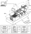
本実施形態を図面を参照しながら以下に説明する。図1は、本開示である実装システム10の一例を示す概略説明図である。図2は、撮像ユニット14の一例を示す概略説明図である。図3は、記憶部42に記憶された情報の一例を示す説明図である。なお、本実施形態において、左右方向(X軸)、前後方向(Y軸)及び上下方向(Z軸)は、図1、2に示した通りとする。This embodiment will be described below with reference to the drawings. FIG. 1 is a schematic explanatory diagram showing an example of a
実装システム10は、例えば、処理対象物30に部品31を実装処理する装置であり、実装装置11と、供給装置25とを備えている。実装装置11は、搬送装置12と、撮像ユニット14と、実装部20と、制御装置40とを備えている。処理対象物30は、部品31の突出部33を挿入する挿入部を備えたものとすれば特に限定されないが、例えば、基板や、3次元形状の基材(立体物)などが挙げられる。The
部品31は、電子部品であり、本体32と、突出部33とを有する。突出部33は、端子ピンであり、本体32に複数形成されている。部品31は、突出部33が処理対象物30の挿入部に挿入されて固定される。突出部33は、先端に向けて細く形成されるテーパ面を有するテーパ部34と、先端面である先端部35とがその先端側に形成されている。テーパ部34は、例えば、処理対象物30の挿入部に突出部33が挿入しやすいように形成されている。このテーパ部34は、部品種別によって、平面や曲面など、突出部33の形状に適した形状で適宜形成されている。また、部品31は、突出部33である端子に極性がある場合、本体32の下面に、本体32の方向を規定するマークが形成されている(図3の輪郭形状モデル44参照)。なお、説明の便宜のため、以下では突出部33を「端子」や「ピン」とも称する。
The
搬送装置12は、処理対象物30の搬入、搬送、実装位置での固定、搬出を行うユニットである。搬送装置12は、間隔を開けて設けられた1対のコンベアベルトにより処理対象物30を搬送する。The
撮像ユニット14は、実装部20に採取され保持された状態の部品31の下面側の画像を撮像する装置である。撮像ユニット14は、搬送装置12と供給装置25との間に配設されている。この撮像ユニット14は、撮像部15と、照明部16とを備えている。撮像部15の撮像範囲は、図2に示すように、撮像部15の上方である。撮像部15は、例えば、CMOSイメージセンサやCCDイメージセンサなど、受光により電荷を発生させ発生した電荷を出力する撮像素子を有する。この撮像部15は、本体32と突出部33との距離の被写界深度を少なくとも有する。照明部16は、実装部20に保持された部品31に光を照射するものであり、部品31へ照射される光の明るさ(光量)、光の波長及び光の照射位置などを調整可能な光源である。照明部16は、部品31に対して側方から光を照射する側射ランプ17と部品31に対して下方から光を照射する落射ランプ18とを少なくとも備えている。この照明部16は、側射ランプ17と落射ランプ18とを同時に又は別々に点灯可能に構成されている。また、照明部16は、撮像部15からの距離が異なる突出部33の先端及び本体32のそれぞれの被写体を同時に照明可能に構成されている。この撮像ユニット14は、部品31の移動なしに、側射ランプ17での側射照明による本体32及び突出部33の画像と、落射ランプ18での落射照明による本体32及び突出部33の画像とを撮像可能に構成されている(図2参照)。なお、撮像ユニット14は、側射ランプ17及び落射ランプ18を同時に点灯させて被写体である本体32及び突出部33を撮像することもできる。撮像ユニット14は、部品31を保持した多関節アームロボット21が撮像部15の上方で停止する際、又は移動中に部品31の画像を撮像し、撮像画像を制御装置40へ出力する。制御装置40は、この撮像画像によって、部品31の形状及び部位が正常であるか否かの検査や、部品31の採取時の位置や回転などのずれ量の検出などを実行することができる。The
実装部20は、部品31を処理対象物30へ配置させる装置である。実装部20は、多関節アームロボット21と、採取部材22と、カメラ23とを備えている。多関節アームロボット21は、回動軸を中心に回動する第1アームや第2アームを接続した作業ロボットである。採取部材22は、部品31を採取して処理対象物30に配置する作業を行う部材であり、多関節アームロボット21の先端に回動可能に接続されている。採取部材22は、例えば、負圧により部品31を吸着して採取するノズルとしてもよいし、部品31を物理的に把持して採取するメカニカルチャックとしてもよい。カメラ23は、下方を撮像するものであり、例えば、供給装置25に載置された部品31を撮像し、部品31の姿勢などを認識する際に使用される。このカメラ23は、多関節アームロボット21の先端に固定されている。The
供給装置25は、部品31を供給する装置である。供給装置25は、供給載置部26と、加振部27と、部品供給部28とを備えている。供給載置部26は、載置面を有し姿勢不定の部品31を載置し、前後方向へ移動させるベルトコンベアとして構成されている。加振部27は、供給載置部26に振動を与え、供給載置部26上の部品31の姿勢を変更させるものである。部品供給部28は、供給載置部26の後方上部に配設されており(不図示)、部品31を収容して供給載置部26へ供給する装置である。部品供給部28は、載置面上の部品が所定数未満になるか、又は定期的に供給載置部26へ部品31を放出する。実装部20は、多関節アームロボット21、採取部材22及びカメラ23を用い、供給載置部26上で採取、配置可能な姿勢の部品31を認識してこれを採取する。The
制御装置40は、CPU41を中心とするマイクロプロセッサを有しており、搬送装置12、撮像ユニット14、実装部20及び供給装置25などを含む装置全体の制御を司る。CPU41は、撮像ユニット14の画像処理を実行する画像処理装置における画像制御部と、多関節アームロボット21の制御を行う実装装置における実装制御部との機能を兼ね備えている。この制御装置40は搬送装置12や撮像ユニット14、実装部20、供給装置25へ制御信号を出力する一方、搬送装置12や撮像ユニット14、実装部20、供給装置25からの信号を入力する。制御装置40は、CPU41のほか、記憶部42や、表示装置47、入力装置48を備えている。記憶部42は、各種アプリケーションプログラムや各種データファイルを記憶する、HDDやフラッシュメモリなどの大容量の記憶媒体である。表示装置47は、実装システム10に関する情報や各種入力画面などを表示するディスプレイである。入力装置48は、作業者が入力するキーボードやマウスなどを含む。The
記憶部42には、例えば、部品31を処理対象物30へ実装する実装ジョブとしての実装条件情報や、部品31の認識に用いられる部品モデル43などが記憶されている。実装条件情報は、部品31を処理対象物30へ実装する配置位置や配置数などの情報が含まれている。部品モデル43は、部品31の基準データであり、図3に示すように、部品ID、照明方法、輪郭形状モデル44、突出部モデル45及び挿入部モデル46などが含まれる。部品IDは、部品31を特定する識別情報であり、予め部品31の種別ごとに付与されている。照明方法は、部品モデル43を生成する撮像画像を撮像したときの照明方法を特定する情報であり、側射照明及び落射照明のうち少なくとも一方である。輪郭形状モデル44は、本体32を規定する基準データである。輪郭形状モデル44には、本体32の形状、方向(端子の極性)のほか本体32のサイズなどが規定されている。輪郭形状モデル44には、本体32の方向を規定するマークの形状や配置位置なども含まれている。突出部モデル45は、端子などの突出部33を規定する基準データである。突出部モデル45には、突出部33のピッチなども含む突出部33の位置や、数、先端部の特徴などが含まれている。先端部の特徴には、例えば、先端部35の形状、そのサイズ、および信号レベルなどが含まれる。先端部の形状には、例えば、円、正方形、長方形、台形、その他任意の形状などが含まれる。サイズには、半径(円)、幅/高さ(矩形)、幅1/幅2/高さ(台形)、幅/高さなどの情報が含まれる。信号レベルには、所定の照明で撮像した際の先端部の信号レベルやその周辺部の信号レベルなどが含まれる。また突出部モデル45には、更に、突出部33のサイズや本体32に配設された1以上の突出部33を含む突出部領域Aの情報などが含まれている。挿入部モデル46は、突出部33が挿入される、処理対象物30に形成された挿入部を規定する基準データである。挿入部モデル46には、挿入部のピッチなども含む挿入部の位置や、数、挿入部の形状を含む特徴、そのサイズなどの情報が含まれている。The
次に、こうして構成された本実施形態の実装システム10の動作、まず制御装置40が部品モデル43を生成する処理について説明する。図4は、CPU41が実行する部品モデル生成処理ルーチンの一例を示すフローチャートである。このルーチンは、記憶部42に記憶され、部品31を利用する前に実行される。このルーチンを開始すると、まず、CPU41は、部品31を撮像位置で保持するよう多関節アームロボット21を制御し、照明部16の照明方法を設定する(S110)。CPU41は、初期値が側射照明で、次が落射照明を照明方法に設定する。次に、CPU41は、テーパ部34と先端部35とにコントラストが発生するよう撮像ユニット14の照明強度と露光時間を調節して設定する(S120)。次に、CPU41は、設定した条件で部品31を撮像し(S130)、全ての照明方法で部品31を撮像したか否かを判定し(S140)、全ての照明方法で撮像していないときには、S110以降の処理を実行する。即ち、照明方法を変更して落射照明とし、テーパ部34と先端部35とにコントラストが発生するよう照明強度と露光時間とを定めて部品31を撮像する。なお、S110では、更に、側射照明及び落射照明を同時点灯させる照明方法で部品31を撮像してもよい。同時照明では、検出効率を改善することができる場合がある。Next, the operation of the mounting
図5は、側射照明と落射照明とで得られる撮像画像の相違を示す説明図である。図5に示すように、側射照明で突出部33を撮像すると、照明の反射により、テーパ部34が白(明部)、先端部35が黒(暗部)である撮像画像が得られる。一方、落射照明で突出部33を撮像すると、照明の反射により、テーパ部34が黒(暗部)、先端部35が白(明部)である撮像画像が得られる。部品31のようなリード付き電子部品では、ほとんどの場合で側射照明が突出部33の先端部を認識する画像取得が有効であるが、一部の部品やキャリブレーション時に落射照明がよいこともあるため、撮像ユニット14では、両照明の少なくとも一方で撮像画像を取得することができるよう構成されている。
Figure 5 is an explanatory diagram showing the difference between the captured images obtained by side illumination and incident illumination. As shown in Figure 5, when the
次に、CPU41は、部品31の画像認識に好適な照明方法および撮像画像を選択する(S150)。CPU41は、例えば、側射照明及び落射照明の撮像画像のうち突出部33の先端部35を検出しやすい撮像画像を選択するものとしてもよい。CPU41は、例えば、突出部33の先端部35の縁部(テーパ部34の領域)が本体32と区別しやすい撮像画像を選択するものとしてもよい。即ち、CPU41は、テーパ部34と先端部35とのコントラストに加え、本体32とのコントラストを加味して照明方法および撮像画像を選択するものとしてもよい。あるいは、S150では、作業者が好適な照明方法および撮像画像を選択するものとしてもよい。Next, the
次に、CPU41は、部品情報及び挿入部情報を取得する(S160)。部品情報は、部品31の製造会社が提供する情報であり、例えば、本体32のサイズ、形状、方向や、突出部33の位置、数、および複数の突出部間のピッチ(距離)などの情報が含まれている。突出部33の位置には、行/列数、行/列ピッチなどの情報も含まれるものとする。この部品情報には、突出部33の先端形状などの情報は含まれていない。また、挿入部情報は、処理対象物30の製造会社が提供する情報であり、例えば、挿入部の位置、数、形状、サイズなどの情報、より具体的には、穴径、行/列数、ピン数、除外ピン数、列ピッチ、行ピッチなどの情報が含まれている。除外ピン数とは、等ピッチのピン列の中に存在しないピン数をいう。CPU41は、部品情報や挿入部情報を提供されたデータで取得するものとしてもよいし、CADデータから抽出して取得するものとしてもよいし、作業者が仕様書から入力したデータを取得するものとしてもよい。Next, the
次に、CPU41は、撮像画像を用いて、本体32の形状及び方向の情報を含み、更にサイズの情報を含む輪郭形状モデル44を生成する(S170)。輪郭形状モデル44を生成するに際して、CPU41は、部品情報を用いてもよい。また、CPU41は、本体32における極性や方向を示すマークなどの特徴も輪郭として抽出するものとする。次に、CPU41は、突出部33の先端部35が存在する部分を囲うように突出部領域Aを設定する(S180,後述図7C参照)。CPU41は、突出部33の位置情報を用いて、突出部33の存在する領域に対して所定のマージンを設けて突出部領域Aを設定する。所定のマージンは、例えば、突出部33の誤検出をより抑制可能な値を経験的に求めてその値に定めることができる。次に、CPU41は、挿入部情報に基づいて、挿入部の位置、数及び穴のサイズを含み、形状などの特徴を含む挿入部モデル46を生成する(S190)。Next, the
続いて、CPU41は、撮像画像から、突出部33の位置、数及び先端部を検出し、さらにその特徴を分析し(S200)、分析した情報に基づいて、突出部33の位置、数、先端部35の特徴の情報を含み、更にサイズの情報を含む突出部モデル45を生成する(S210)。突出部モデル45を生成するに際して、CPU41は、部品情報を用いてもよい。また、CPU41は、S200において、検出した突出部33に番号を付与してもよい。また、突出部33の位置には、行/列数、行/列ピッチなどの情報も含まれるものとする。また、先端部35の特徴には、先端部35の形状(円、正方形、長方形、台形など)とそのサイズ、先端部およびその周辺領域の信号レベルなども含まれるものとしてもよい。そして、CPU41は、撮像画像の照明方法と、輪郭形状モデル44と、突出部モデル45と、挿入部モデル46とを部品IDに対応づけ、部品モデル43(図3参照)を生成し、記憶部42に記憶させ、このルーチンを終了する。このようにして、制御装置40は、部品31の基本データ及び形状テンプレートとしての部品モデル43を実装システム10を用いて生成することができる。Next, the
次に、部品モデル43を用いて、処理対象物30の挿入部へ突出部33を挿入させて部品31を配置する実装処理について説明する。図6は、CPU41が実行する実装処理ルーチンの一例を示すフローチャートである。図7は、部品31の画像認識処理の概要を説明する説明図であり、図7Aが部品画像51の説明図、図7Bが本体52の輪郭形状認識処理、図7Cが突出部領域Aの設定、図7Dが先端部35の認識、図7Eが挿入部を適用した説明図である。実装処理ルーチンは、記憶部42に記憶され、作業者による開始指示により実行される。Next, a mounting process will be described in which the
このルーチンを開始すると、まず、CPU41は、実装条件情報及び部品モデル43を読み出して取得する(S300)。次に、CPU41は、搬送装置12に処理対象物30を実装位置まで搬送させ、固定処理させ(S310)、供給載置部26に部品31を供給するよう部品供給部28を制御する(S320)。次に、CPU41は、多関節アームロボット21を制御し、カメラ23を供給載置部26の上方に移動させ、供給載置部26上の部品31をカメラ23に撮像させ、採取可能な部品31を認識する処理を行う(S330)。CPU41は、供給載置部26上の部品31のうち、突出部33が下側、本体32が上側にある部品31を採取可能部品として認識する。なお、採取可能な部品31がないときには、加振部27を駆動して部品31の姿勢を変更させる。また、供給載置部26上に部品31が存在しないときには、部品供給部28を駆動し、部品31を供給載置部26上へ供給させる。When this routine is started, first, the
次に、部品31は、多関節アームロボット21及び採取部材22を駆動し、部品31を採取部材22に採取させ、撮像ユニット14の上部へ移動させる(S340)。実装部20では、採取部材22の中心位置が画像中心に移動するように、予め撮像位置や多関節アームロボット21の制御を調整する。次に、CPU41は、部品種に応じた照明方法を含む撮像条件で、部品31を突出部33側から撮像ユニット14に撮像させる(S350)。CPU41は、照明方法や撮像条件を部品モデル43から取得する。次に、CPU41は、撮像画像から部品31の領域を抽出し(図7A)、本体32の中心位置及び本体32の方向(極性)を認識する(S360)。図7Aに示すように、部品画像51には、画像としての本体52、突出部53、先端部55などが含まれている。部品31の領域は、輪郭形状モデル44のパターンマッチングによって抽出することができる。本体32の方向は、マーク或いは方向を認識可能な形状特徴を検出し、パターンマッチングを行うことによって、認識することができる(図7B)。次に、CPU41は、検出された部品31の中心位置を用いて、視差補正を行い、突出部領域Aの位置を設定する(S370)。Next, the
図8は、視差を加味して突出部領域Aの設定位置を補正する説明図であり、図8Aが視差補正前、図8Bが視差補正後の説明図である。図9は、突出部の長さ及び部品31と撮像部15との距離の説明図である。部品31では、図9に示すように、撮像部15と先端部35との距離に比して、撮像部15と本体32との距離がより遠くなるため、図8に示すように、部品31が画像中心から外れると、本体32や突出部33の側面が見えるように、視差が生じる。部品31が画像中心にあるときには問題ないが、画像周辺部にあるときは、先端部35の位置が本体32に対してずれる。この状態で突出部領域Aを設定すると、適切な先端部35の検出を行うことができない場合が生じる。CPU41は、撮像画像に対して画像中央を基準とした視差補正を実行し、突出部領域Aを部品画像51上に設定したうえで突出部33の位置を検出する。視差補正において、CPU41は、突出部33の先端部35の1画素あたりの分解能Rp(μm/pixel)、所定長さあたりの分解能変化量である単位分解能Ru(μm/pixel)、突出部33の本体32からの長さPL(mm)としたときに、Rp-Ru×PLの視差補正を実行する(図8B)。このような視差補正を行うことによって、CPU41は、先端部35をより確実に認識することができる。
Figure 8 is an explanatory diagram for correcting the setting position of the protrusion region A taking into account parallax, where Figure 8A is an explanatory diagram before parallax correction and Figure 8B is an explanatory diagram after parallax correction. Figure 9 is an explanatory diagram for the length of the protrusion and the distance between the
次に、CPU41は、突出部領域Aの内側の領域において、各突出部33の先端部35の位置と先端部35の中心位置とを推定し、認識する処理を行う(S380)。CPU41は、突出部モデル45を用いて、突出部領域A内でパターンマッチングを行うことによって、先端部35の位置を認識することができる。突出部モデル45には、突出部33の位置や数の情報が含まれており、CPU41は、おおよその先端部35の位置を推定することができる(図3参照)。また、部品モデル43には、先端部35の形状特徴が含まれているため、これを用いてCPU41は、形状モデルを自動的に生成し、パターンマッチングを行う。このとき、先端部35は、ひとつひとつの先端部毎に形状、サイズ、信号レベルの個体差があるので、CPU41は、これらのパラメータを変動させながらパターンマッチングを行う。特に形状に関しては、モデル生成時の個体では円でのマッチングスコアが高い場合であっても別の個体では長方形の方がマッチングスコアが高くなるケースがある。このため、CPU41は、突出部モデル45に記載された数量の突出部33が検出できない場合は、別形状の形状モデルを生成して再度パターンマッチングを行い、認識率を向上させるものとしてもよい。CPU41は、全ての先端部35の位置を検出すると、全ての先端部35の中心位置を算出する。Next, the
先端部35の中心位置を検出すると、CPU41は、先端部35の中心位置と挿入部との位置関係から最適な補正位置を算出する(S390)。CPU41は、先端部35の位置のピッチと位置のばらつき量と、挿入部の穴との位置関係から補正値を求める。より具体的には、CPU41は、各先端部35の中央位置と挿入部の穴との距離を計測し、その距離の最大値が最小となる位置を最適補正値とする。次に、CPU41は、この部品31が挿入部へ挿入可能であるかを判定する(S400)。突出部33は、曲がるなど、その先端部35が常に等ピッチになっているとは限らない。CPU41は、挿入部の穴と突出部33の先端外形との距離を計算し、全ての突出部33と穴の距離が所定の許容閾値以上であるときに部品31が挿入可能であると判断する。この許容閾値は、例えば、突出部33が挿入部の内壁に干渉しない値に経験的に求められている。When the center position of the
図10は、挿入部モデル46を用いた挿入可否判定の一例を示す説明図である。CPU41は、上記補正値を適用した状態で、図10に示すように、挿入部モデル46の穴径を標準穴径から小さくしながら穴と突出部33の先端部35との干渉をチェックし、穴と先端部35とが干渉するときの穴径と標準穴径との差が許容閾値を超えているか否かに基づいてこの判定を行うことができる。このように、CPU41は、第1サイズ及び第1サイズより小さな第2サイズの挿入部を少なくとも想定して突出部33が挿入部に挿入する際に干渉するか否かを判定するのである。
Figure 10 is an explanatory diagram showing an example of insertion feasibility determination using the
S400で、部品31が挿入部に挿入可能であるときには、CPU41は、位置補正を行い、部品31を処理対象物30の予め定められた配置位置へ配置させる(S410)。このとき、CPU41が部品31を処理対象物30へ配置させると、判定結果同様に、突出部33が処理対象物30の挿入部に挿入される。一方、S400で、部品31が挿入部に挿入可能でないときには、CPU41は、この部品31の使用を中止して廃棄すると共に、その旨のメッセージを作業者へ報知する(S420)。作業者への報知は、例えば、表示装置47上に部品31が挿入可能でない旨のメッセージやアイコンなどを表示させるものとする。
When it is determined in S400 that the
S420のあと、または、S410のあと、CPU41は、次の配置するべき部品31があるか否かを判定し(S430)、次の部品31があるときには、S320以降の処理を実行する。即ち、CPU41は、必要に応じて供給載置部26に部品31を供給し、採取可能な部品31を認識し、部品31を採取して撮像ユニット14で撮像し、先端部35の認識及び挿入可能かを判定して配置させる処理を繰り返し実行する。一方、S430で、この処理対象物30に配置する次の部品がないときには、CPU41は、次に部品31を配置すべき処理対象物30があるか否かを判定し(S440)、次の処理対象物30があるときには、S310以降の処理を実行する。即ち、CPU41は、部品31の配置が終了した処理対象物30を排出させ、次の処理対象物30を搬入し、S320以降の処理を実行する。一方、S440で次の処理対象物30がないときには、CPU41は、このルーチンを終了する。After S420 or S410, the
ここで、本実施形態の構成要素と本開示の構成要素との対応関係を明らかにする。本実施形態のCPU41が本開示の画像制御部及び実装制御部に相当し、実装部20が実装部に相当し、撮像部15が撮像部に相当し、照明部16が照明部に相当し、供給装置25が供給装置に相当する。また、制御装置40が画像処理装置に相当し、実装装置11が実装装置に相当する。なお、本実施形態では、実装システム10の動作を説明することにより本開示の画像処理方法及び実装方法の一例も明らかにしている。Here, the correspondence between the components of this embodiment and the components of this disclosure will be clarified. The
以上説明した本実施形態の制御装置40では、部品31に対して側方から光を照射した突出部33と、部品31に対して下方から光を照射した本体32との撮像画像から本体32の形状と突出部33の位置と突出部33の数と突出部33の先端部35とを検出し、挿入部の情報を取得し、本体32の形状及び方向を含む輪郭形状モデル44と突出部33の位置、数、先端部35の特徴を含む突出部モデル45とを含む部品モデル43を生成する。この制御装置40では、例えば、突出部33の先端部35にレーザを照射してこの先端部35に焦点を合わせて撮像するような特別な照明部や撮像部を要することなく、側方からの側射照明と下方からの落射照明とによって突出部33や本体32をより確実に検出可能な撮像画像を得ることができる。この制御装置40では、このように得られた撮像画像を用いて部品31の基準データとなる部品モデル43を構築することができる。そして、実装装置11は、この部品モデル43を用いて突出部33を有する部品31の認識を実行し、実装処理を実行することができる。したがって、この制御装置40では、本体32から突出した突出部33を有する部品31を実装するに際して、より簡便な構成でより確実に実装処理を実行することができる。また、制御装置40は、挿入部の情報から挿入部の位置、数及びサイズを含む挿入部モデル46の情報を含む部品モデル43を生成することができる。In the
また、本実施形態の実装装置11では、側射照明及び落射照明のうち少なくとも一方で得られた撮像画像から本体32の形状と突出部33の位置と突出部33の数と突出部33の先端部35とを検出し、本体32の形状及び方向を含む輪郭形状モデル44と、突出部33の位置、数、先端部35の特徴を含む突出部モデル45とを生成し、挿入部の情報から挿入部の位置、数及びサイズを含む挿入部モデル46を生成し、輪郭形状モデル44と突出部モデル45と挿入部モデル46とを含む部品モデル43を生成する。また、この実装装置11では、取得した部品31の撮像画像から本体32の形状と突出部33の位置と突出部33の数と突出部の先端部35とを検出し、部品モデル43を利用してこの部品31を処理対象物30へ実装部20に配置させる。この実装装置11では、生成された部品モデル43で使用された照明を用い、実装部20により採取された部品31を撮像した撮像画像を取得し、取得した撮像画像から本体32の形状と突出部33の位置と突出部33の数と突出部33の先端部35とを検出する。そして、この実装装置11は、部品モデル43を利用してこの部品31を処理対象物30へ実装部20に配置させる。したがって、この実装装置11では、本体32から突出した突出部33を有する部品31を実装するに際して、より簡便な構成でより確実に実装処理を実行することができる。In addition, in the mounting
また、CPU41は、部品モデル43を利用してこの部品31が処理対象物30に配置可能か否かを判定する。突出部33を有する部品31では、突出部33の変形など、その形状によっては、挿入部に挿入できない場合がある。この実装装置11では、部品モデル43を利用して部品31が使用可能である情報を事前に取得することができ、より確実に実装処理を実行することができる。更に、CPU41は、挿入部モデル46を用いて、第1サイズ及び第1サイズより小さな第2サイズの挿入部を少なくとも想定して突出部33が挿入部に挿入する際に干渉するか否かを判定する。この実装装置11では、挿入部のサイズをより小さく変更することによって、部品31が挿入部に干渉せずに使用可能かの情報を取得することができる。更にまた、CPU41は、撮像画像に対して画像中央を基準とした視差補正を実行し、突出部33の位置を検出する。本体32と突出部33との距離の被写界深度を少なくとも有する撮像部15においては、突出部33の先端部35よりも本体32が遠いことから、画像の中央からより外れた画像外周側では、より視差が生じる。この実装装置11では、このような視差を補正することによって、突出部33の位置をより適正に検出し、部品モデル43をより適正に用いることができる。このとき、CPU41は、突出部33の先端部35の1画素あたりの分解能Rp、所定長さあたりの分解能変化量である単位分解能Ru、突出部の本体からの長さPLとしたときに、Rp-Ru×PLの視差補正を実行する。この実装装置11では、分解能や突出部の長さを考慮して、より適切な視差補正を実行することができる。
The
本実施形態の実装システム10は、上述した実装装置11と、部品31を不定方向で載置領域に供給する供給装置25とを備え、実装部20は、多関節アームロボット21を有する。この実装システム10では、突出部31を有する部品を簡便に供給し、汎用的な多関節アームロボット21を用いて処理対象物30に突出部33を挿入して部品31を配置することができる。The mounting
また、実装装置11において、撮像部15は本体32と突出部33との距離の被写界深度を少なくとも有するため、本体32と突出部33とを同一画像上に撮像することができる。また、CPU41は、部品モデル43を設定する撮像画像として、側射照明及び落射照明のうち少なくとも一方で得られた撮像画像を選択するため、より好適な部品モデル43を生成することができる。このとき、CPU41は、側射照明の撮像画像と落射照明の撮像画像とのうち突出部33の先端部35を検出しやすい撮像画像を選択するめ、側射照明と落射照明とを使い分けることによって、部品31が有する突出部33の先端部35を検出することができる。また、CPU41は、側射照明の撮像画像と落射照明の撮像画像とのうち、突出部33の先端部35の縁部が本体32と区別しやすい撮像画像を選択する。この制御装置40では、側射照明か落射照明かのいずれかにより、先端部35の縁部の撮像色を変更することが可能であり、その縁部の撮像色が本体32の色と異なるものとすることにより、突出部33の先端部35をより確実に認識することができる。In addition, in the mounting
更に、CPU41は、1以上の突出部33が含まれる突出部領域Aを突出部モデル45に含む部品モデル43を生成する。この制御装置40では、突出部33の位置を領域単位で取り扱うことができるため、より効率よく突出部33を認識することができる。また、CPU41は、部品31の方向を含む輪郭形状モデル44を生成するため、部品本体の方向も含めた部品モデル43を構築することができる。Furthermore, the
また、実装システム10は、多関節アームロボット21を有する実装装置11と、部品31を不定方向に載置する供給装置25とを用いて、端子を挿入部へ挿入する実装処理を実行可能であるため、汎用装置を使って、比較的安価に複雑な実装処理を実行することができる。更に、実装システム10では、わずかなパラメータ入力を行えば、部品モデル43を生成することができるため、作業者の画像処理設定の手間を最小限に抑えることができる。更にまた、特殊なレーザ照明や、被写界深度の小さい特殊な撮像部を用いる専用装置では、突出部33の先端部35と本体32とを同一画像に撮像することは不可能であったが、この実装システム10では、1回の撮像で先端部35と本体32とを撮像可能であり、先端部35と本体32の方向とを1つの画像により実行可能であるため、処理時間の短縮を図ることができる。そして、実装システム10では、端子長にばらつきがある部品31においても、1回の撮像によって、先端部35の認識を実行することができる。そしてまた、実装システム10は、1つ1つの端子を認識し、その端子間の距離等も計測するため、端子折れや曲がりなどの不良品の検出と廃棄とが可能になるため、生産現場での作業性がより向上する。In addition, the mounting
なお、本開示は上述した実施形態に何ら限定されることはなく、本開示の技術的範囲に属する限り種々の態様で実施し得ることはいうまでもない。It goes without saying that the present disclosure is in no way limited to the above-described embodiments, and may be implemented in various forms as long as they fall within the technical scope of the present disclosure.
例えば、上述した実施形態では、実装装置11の制御装置40が画像処理装置の機能を有するものとしたが、特にこれに限定されず、実装装置11とは別に画像処理装置を設けるものとしてもよい。同様に、上述した実施形態では、CPU41が画像制御部と実装制御部の機能を有するものとしたが、特にこれに限定されず。CPU41とは別に画像制御部を設けるものとしてもよい。この実装装置11においても、本体から突出した突出部を有する部品を実装するに際して、より簡便な構成でより確実に実装処理を実行することができる。For example, in the above-described embodiment, the
上述した実施形態では、輪郭形状モデル44には、本体32の形状、方向(端子の極性)のほか本体32のサイズなどが規定されているものとしたが、これに限定されず、他の因子を含んでもよいし、少なくとも本体32の形状及び方向を含むものとしてもよい。また、上述した実施形態では、突出部モデル45には、突出部33の位置や、数、先端部の特徴、突出部33のサイズ、突出部領域Aの情報などが含まれているものとしたが、これに限定されず、他の因子を含んでもよいし、少なくとも、突出部33の位置、数、先端部35の特徴を含むものとしてもよい。更に、上述した実施形態では、挿入部モデル46には、挿入部のピッチなども含む挿入部の位置や、数、挿入部の形状を含む特徴、そのサイズなどの情報が含まれているものとしたが、これに限定されず、他の因子を含んでもよいし、少なくとも挿入部の位置、数及びサイズを含むものとしてもよい。また、上述した実施形態では、部品モデル43は、輪郭形状モデル44と、突出部モデル45と、挿入部モデル46とを含むものとしたが、特にこれに限定されず、例えば、挿入部モデル46を省略してもよい。部品モデル43は、突出部33を挿入部に挿入可能となる情報を適宜含むものとすればよい。In the above embodiment, the
上述した実施形態では、撮像画像の視差補正を行うに際して、分解能Rp、単位分解能Ru、突出部長さPLとを用いてRp-Ru×PLの視差補正を実行するものとしたが、これに限定されず、これらの因子に加えて、あるいは変えて他の因子を用いて視差補正を実行するものとしてもよい。あるいは、CPU41は、視差補正を省略してもよい。このとき、CPU41は、突出部領域Aを用いずにより広範囲で先端部35を認識する処理を実行することが望ましい。In the above-described embodiment, when performing parallax correction of the captured image, the resolution Rp, the unit resolution Ru, and the protrusion length PL are used to perform parallax correction of Rp-Ru×PL, but this is not limited thereto, and parallax correction may be performed using other factors in addition to or instead of these factors. Alternatively, the
上述した実施形態では、CPU41は、部品モデルの生成において、側射照明で撮像された撮像画像か、落射照明で撮像された撮像画像かのいずれかを用いて部品モデルを生成するものとしたが、特にこれに限定されず、側射照明及び落射照明を同時点灯した撮像画像から部品モデルを生成するものとしてもよい。また、CPU41は、側射照明の撮像画像を画像処理し、落射照明の撮像画像を画像処理し、2つの画像処理結果を合成して最終的に1つの画像処理結果を得ることにより、部品モデルを生成するものとしてもよい。CPU41は、部品31に応じて適切な照明方法や画像処理方法を選択すればよい。なお、CPU41は、実装部20が採取した部品31に対して部品モデルを用いて画像処理する際においても、上記と同様の照明方法や画像処理方法を採用することができる。In the above-described embodiment, the
上述した実施形態では、部品31の突出部33は、端子ピンであるものとして説明したが、処理対象物30の挿入部(穴部)に挿入される部位であれば、特にこれに限定されない。In the above-described embodiment, the
上述した実施形態では、実装部20は、多関節アームロボット21を有するものとして説明したが、突出部33を挿入部に挿入して部品31を処理対象物30に配置することができるものであれば特にこれに限定されず、例えば、XYロボットの構成を有するものとしてもよい。図11は、別の実装システム10Bの一例を示す説明図である。この実装システム10Bは、実装装置11Bと、管理装置60とを備える。実装装置11Bは、基板30Bを搬送する搬送装置12Bと、フィーダ29を備えた供給装置25Bと、側射照明と落射照明とを実行可能な撮像ユニット14と、実装部20Bと、制御装置40とを備える。実装部20Bは、実装ヘッド21Bと、実装ヘッド21Bに装着された採取部材22Bと、実装ヘッド21BをXY方向に移動させるヘッド移動部24とを備える。撮像ユニット14及び制御装置40は、上述した実施形態と同様である。このような実装装置11Bを用いた場合でも、本体から突出した突出部を有する部品を実装するに際して、より簡便な構成でより確実に実装処理を実行することができる。In the above-described embodiment, the mounting
上述した実施形態では、本開示の画像処理装置を制御装置40として説明したが、特にこれに限定されず、画像処理方法としてもよいし、この画像処理方法をコンピュータが実行するプログラムとしてもよい。また、上述した実施形態では、本開示の実装装置を実装装置11として説明したが、特にこれに限定されず、実装方法としてもよいし、この実装方法をコンピュータが実行するプログラムとしてもよい。In the above-described embodiment, the image processing device of the present disclosure has been described as a
ここで、本開示の画像処理装置や実装装置は、以下のように構成してもよい。例えば、本開示の画像処理装置において、前記画像制御部は、前記挿入部の情報から前記挿入部の位置、数及びサイズを含む挿入部モデルをさらに含む部品モデルを生成するものとしてもよい。この画像処理装置では挿入部の情報を含む部品モデルを生成することができる。Here, the image processing device and mounting device of the present disclosure may be configured as follows. For example, in the image processing device of the present disclosure, the image control unit may generate a part model that further includes an insertion part model including the position, number, and size of the insertion part from information about the insertion part. This image processing device can generate a part model that includes information about the insertion part.
本開示の実装装置は、
本体と前記本体に形成された1以上の突出部とを有する部品の該突出部を処理対象物に形成された挿入部に挿入して前記部品を前記処理対象物に配置する実装部と、
前記部品に対して側方から光を照射する側射照明と前記部品に対して下方から光を照射す落射する照明とを点灯可能な照明部と、
前記本体と前記突出部との距離の被写界深度を少なくとも有し、前記部品を下方から撮像する撮像部と、
上述した画像処理装置で生成された前記部品モデルで使用された照明を用い、前記実装部により採取された前記部品を撮像した撮像画像から前記本体の形状と前記突出部の位置と前記突出部の数と前記突出部の先端部とを検出し、前記画像処理装置で生成された前記部品モデルを利用して該部品を前記処理対象物へ前記実装部に配置させる実装制御部と、
を備えたものである。
The mounting device of the present disclosure is
a mounting section for inserting a protrusion of a component having a main body and one or more protrusions formed on the main body into an insertion section formed on the processing object to place the component on the processing object;
an illumination unit capable of turning on a side illumination that irradiates the component with light from a side and an epi-illumination that irradiates the component with light from below;
an imaging unit having a depth of field of at least the distance between the main body and the protruding portion and configured to image the component from below;
a mounting control unit that detects the shape of the main body, the positions of the protrusions, the number of the protrusions, and the tips of the protrusions from an image of the component captured by the mounting unit using lighting used in the component model generated by the image processing device described above, and causes the mounting unit to place the component on the processing target using the component model generated by the image processing device;
It is equipped with the following:
この実装装置では、上述した画像処理装置で生成された部品モデルで使用された側射照明及び/又は落射照明を用い、実装部により採取された部品を撮像した撮像画像を取得し、取得した撮像画像から本体の形状と突出部の位置と突出部の数と突出部の先端部とを検出する。そして、この実装装置は、画像処理装置で生成された部品モデルを利用してこの部品を処理対象物へ実装部に配置させる。したがって、この実装装置では、本体から突出した突出部を有する部品を実装するに際して、より簡便な構成でより確実に実装処理を実行することができる。また、この実装装置では、上述した画像処理装置を採用した態様に応じた効果を得ることができる。 In this mounting device, the side lighting and/or epi-illumination used in the component model generated by the image processing device described above is used to acquire an image of the component collected by the mounting unit, and the shape of the main body, the positions of the protrusions, the number of protrusions, and the tips of the protrusions are detected from the acquired image. Then, this mounting device uses the component model generated by the image processing device to place the component in the mounting unit on the processing object. Therefore, when mounting a component having a protrusion protruding from the main body, this mounting device can perform the mounting process more reliably with a simpler configuration. Furthermore, this mounting device can obtain effects according to the aspect in which the image processing device described above is adopted.
本開示の実装装置において、前記実装制御部は、前記部品モデルを利用して該部品が前記処理対象物に配置可能か否かを判定するものとしてもよい。突出部を有する部品では、突出部の変形など、その形状によっては、挿入部に挿入できない場合がある。この実装装置では、部品モデルを利用して部品が使用可能である情報を事前に取得することができ、より確実に実装処理を実行することができる。 In the mounting device of the present disclosure, the mounting control unit may use the part model to determine whether or not the part can be placed on the processing object. A part with a protrusion may not be able to be inserted into the insertion part depending on the shape of the protrusion, such as deformation of the protrusion. In this mounting device, the part model can be used to obtain information in advance as to whether the part can be used, allowing the mounting process to be performed more reliably.
本開示の実装装置において、前記実装制御部は、前記挿入部モデルを用いて、第1サイズ及び前記第1サイズより小さな第2サイズの前記挿入部を少なくとも想定して前記突出部が前記挿入部に挿入する際に干渉するか否かを判定するものとしてもよい。この実装装置では、複数の挿入部のサイズを用いて、部品が挿入部に干渉せずに使用可能かの情報を取得することができ、より確実に実装処理を実行することができる。In the mounting device of the present disclosure, the mounting control unit may use the insertion part model to determine whether or not the protrusion will interfere with the insertion part when inserted into the insertion part, assuming at least a first size and a second size smaller than the first size. This mounting device can use multiple insertion part sizes to obtain information on whether a component can be used without interfering with the insertion part, and can more reliably execute the mounting process.
本開示の実装装置において、前記実装制御部は、前記撮像画像に対して画像中央を基準とした視差補正を実行し、前記突出部の位置を検出するものとしてもよい。本体と前記突出部との距離の被写界深度を少なくとも有する撮像部においては、突出部の先端部よりも本体が遠いことから、画像の中央からより外れた画像外周側では、より視差が生じる。この実装装置では、このような視差を補正することによって、突出部の位置をより適正に検出し、部品モデルをより適正に用いることができる。このとき、前記実装制御部は、前記突出部の先端部の1画素あたりの分解能Rp、所定長さあたりの分解能変化量である単位分解能Ru、突出部の本体からの長さPLとしたときに、Rp-Ru×PLの前記視差補正を実行するものとしてもよい。この実装装置では、分解能や突出部の長さを考慮して、より適切な視差補正を実行することができる。In the mounting device of the present disclosure, the mounting control unit may perform parallax correction on the captured image based on the center of the image to detect the position of the protrusion. In an imaging unit having at least a depth of field of the distance between the main body and the protrusion, the main body is farther away than the tip of the protrusion, so that more parallax occurs on the outer periphery of the image that is further away from the center of the image. In this mounting device, by correcting such parallax, the position of the protrusion can be more appropriately detected and the component model can be more appropriately used. In this case, the mounting control unit may perform the parallax correction of Rp-Ru×PL, where Rp is the resolution per pixel of the tip of the protrusion, Ru is the unit resolution that is the amount of resolution change per predetermined length, and PL is the length of the protrusion from the main body. In this mounting device, more appropriate parallax correction can be performed taking into account the resolution and the length of the protrusion.
本開示の実装システムは、上述したいずれかに記載の実装装置と、前記部品を不定方向で載置領域に供給する供給装置と、を備え、前記実装部は、多関節アームロボットを有するものである。この実装システムでは、突出部を有する部品を簡便に供給し、比較的汎用的な多関節アームロボットを用いて処理対象物に配置することができる。The mounting system of the present disclosure includes any one of the mounting devices described above and a supply device that supplies the components to a placement area in a random direction, and the mounting unit has an articulated arm robot. In this mounting system, components having protruding parts can be easily supplied and placed on a processing object using a relatively general-purpose articulated arm robot.
本開示の画像処理方法は、
本体と前記本体に形成された1以上の突出部とを有する部品の該突出部を処理対象物に形成された挿入部に挿入して前記部品を前記処理対象物に配置する実装部を備えた実装装置に用いられる画像処理方法であって、
(a)前記部品に対して側方から光を照射する側射照明と前記部品に対して下方から光を照射する落射照明とを点灯可能な照明部と、前記本体と前記突出部との距離の被写界深度を少なくとも有し前記部品を下方から撮像する撮像部と、を有する撮像ユニットの前記側射照明及び/又は前記落射照明で撮像した撮像画像を取得するステップと、
(b)取得した前記撮像画像から前記本体の形状と前記突出部の位置と前記突出部の数と前記突出部の先端部とを検出するステップと、
(c)前記挿入部の情報を取得するステップと、
(d)前記ステップ(b)の検出結果と前記ステップ(c)で取得した情報に基づいて、前記本体の形状及び方向を含む輪郭形状モデルと、前記突出部の位置、数、先端部の特徴を含む突出部モデルと、前記挿入部の位置、数及びサイズを含む挿入部モデルとを含む部品モデルを生成するステップと、
を含むものである。
The image processing method of the present disclosure includes:
1. An image processing method used in a mounting device including a mounting section that inserts a protrusion of a component having a main body and one or more protrusions formed on the main body into an insertion section formed on a processing object, and places the component on the processing object, comprising:
(a) acquiring an image captured by an imaging unit having an illumination unit capable of turning on a side illumination that irradiates the component with light from the side and an epi-illumination that irradiates the component with light from below, and an imaging unit that has a depth of field of at least the distance between the main body and the protrusion and images the component from below, the imaging unit capturing an image of the component using the side illumination and/or the epi-illumination;
(b) detecting a shape of the main body, positions of the protrusions, the number of the protrusions, and tips of the protrusions from the acquired captured image;
(c) acquiring information about the insertion unit;
(d) generating a part model based on the detection result of step (b) and the information acquired in step (c), the part model including a contour shape model including a shape and direction of the main body, a protrusion model including the positions, number and features of the tip of the protrusion, and an insertion model including the positions, number and size of the insertion;
It includes.
この画像処理方法では、上述した画像処理装置と同様に、特別な照明部や撮像部を要することなく、複数の照明モードによって突出部をより確実に検出可能な撮像画像を得ることができ、本体と突出部とを一度に撮像することができる。このため、この画像処理方法では、本体から突出した突出部を有する部品を実装するに際して、より簡便な構成でより確実に実装処理を実行することができる。なお、この画像処理方法において、上述した画像処理装置の種々の態様を採用してもよいし、また、上述した画像処理装置の各機能を実現するようなステップを追加してもよい。 In this image processing method, as with the image processing device described above, it is possible to obtain an image in which the protrusion can be more reliably detected using multiple illumination modes without requiring a special illumination unit or imaging unit, and it is possible to image the main body and the protrusion at the same time. Therefore, in this image processing method, when mounting a component having a protrusion that protrudes from the main body, it is possible to more reliably perform the mounting process with a simpler configuration. Note that in this image processing method, various aspects of the image processing device described above may be adopted, and steps may be added that realize each function of the image processing device described above.
本開示の実装方法は、
本体と前記本体に形成された1以上の突出部とを有する部品の該突出部を処理対象物に形成された挿入部に挿入して前記部品を前記処理対象物に配置する実装部と、前記部品に対して側方から光を照射する側射照明と前記部品に対して下方から光を照射する落射照明とを点灯可能な照明部と、前記本体と前記突出部との距離の被写界深度を少なくとも有し前記部品を下方から撮像する撮像部と、を備えた実装装置が実行する実装方法であって、
(e)上述した画像処理方法で生成された前記部品モデルで使用された照明を用い、前記実装部により採取された前記部品を撮像した撮像画像を取得するステップと、
(f)取得した前記撮像画像から前記本体の形状と前記突出部の位置と前記突出部の数と前記突出部の先端部とを検出し、前記部品モデルを利用して該部品を前記処理対象物へ前記実装部に配置させるステップと、
を含むものである。
The implementation method of the present disclosure includes:
A mounting method performed by a mounting device including: a mounting unit that places a component, the component having a main body and one or more protrusions formed on the main body, on a processing object by inserting the protrusions into an insertion portion formed on the processing object, an illumination unit that can turn on side illumination that irradiates the component with light from the side and epi-illumination that irradiates the component with light from below, and an imaging unit that has a depth of field of at least the distance between the main body and the protrusions and images the component from below,
(e) acquiring an image of the component captured by the mounting unit using the lighting used in the component model generated by the image processing method described above;
(f) detecting a shape of the main body, a position of the protrusion, a number of the protrusions, and a tip of the protrusion from the acquired captured image, and placing the component on the mounting portion of the processing object using the component model;
It includes.
この実装方法では、上述したいずれかの画像処理装置で生成された部品モデルで使用された照明を用いて取得した撮像画像から本体の形状と突出部の位置と突出部の数と突出部の先端部とを検出する。そして、この実装方法では、部品モデルを利用してこの部品を処理対象物へ実装部に配置させる。したがって、この実装方法では、本体から突出した突出部を有する部品を実装するに際して、より簡便な構成でより確実に実装処理を実行することができる。また、採用した画像処理方法の態様に応じた効果を得ることができる。なお、この実装方法において、上述した実装装置の種々の態様を採用してもよいし、また、上述した実装装置の各機能を実現するようなステップを追加してもよい。In this mounting method, the shape of the main body, the position of the protrusions, the number of protrusions, and the tips of the protrusions are detected from an image captured using the lighting used in a part model generated by any of the image processing devices described above. Then, in this mounting method, the part is placed in the mounting section of the processing target object using the part model. Therefore, in this mounting method, when mounting a part having a protrusion protruding from the main body, the mounting process can be performed more reliably with a simpler configuration. Also, an effect according to the aspect of the image processing method adopted can be obtained. Note that in this mounting method, various aspects of the mounting device described above may be adopted, and steps may be added to realize each function of the mounting device described above.
本開示の画像処理装置、実装装置、実装システム及び画像処理方法は、例えば、電子部品の実装分野に利用可能である。The image processing device, mounting device, mounting system, and image processing method disclosed herein can be used, for example, in the field of electronic component mounting.
10,10B 実装システム、11,11B 実装装置、12,12B 搬送装置、13 搬送部、14 撮像ユニット、15 撮像部、16 照明部、17 側射ランプ、18 落射ランプ、20,20B 実装部、21 多関節アームロボット、21B 実装ヘッド、22、22B 採取部材、23 カメラ、24 ヘッド移動部、25,25B 供給装置、26 供給載置部、27 加振部、28 部品供給部、29 フィーダ、30 処理対象物、30B 基板、31 部品、32 本体、33 突出部、34 テーパ部、35 先端部、40 制御装置、41 CPU、42 記憶部、43 部品モデル、44 輪郭形状モデル、45 突出部モデル、46 挿入部モデル、47 表示装置、48 入力装置、51 部品画像、52 本体、53 突出部、55 先端部、56 挿入部、60 管理装置、A 突出部領域。10, 10B Mounting system, 11, 11B Mounting device, 12, 12B Conveying device, 13 Conveying section, 14 Imaging unit, 15 Imaging section, 16 Illumination section, 17 Side-illumination lamp, 18 Incident-illumination lamp, 20, 20B Mounting section, 21 Articulated arm robot, 21B Mounting head, 22, 22B Picking member, 23 Camera, 24 Head moving section, 25, 25B Supply device, 26 Supply placement section, 27 Vibration section, 28 Part supply section, 29 Feeder, 30 Processing object, 30B Substrate, 31 Part, 32 Main body, 33 Protruding section, 34 Tapered section, 35 Tip section, 40 Control device, 41 CPU, 42 Memory section, 43 Part model, 44 Contour shape model, 45 Protruding section model, 46 Insertion section model, 47 Display device, 48 input device, 51 part image, 52 main body, 53 protrusion, 55 tip portion, 56 insertion portion, 60 management device, A protrusion region.
Claims (10)
前記部品に対して側方から光を照射する側射照明と前記部品に対して下方から光を照射する落射照明とを点灯可能な照明部と、前記本体と前記突出部との距離の被写界深度を少なくとも有し前記部品を下方から撮像する撮像部と、を有する撮像ユニットの前記側射照明及び/又は前記落射照明で撮像した撮像画像を取得し、取得した前記撮像画像から前記本体の形状と前記突出部の位置と前記突出部の数と前記突出部の先端部とを検出し、前記挿入部の情報を取得し、前記本体の形状及び方向を含む輪郭形状モデルと前記突出部の位置、数、先端部の特徴を含む突出部モデルとを含む部品モデルを生成する画像制御部、
を備えた画像処理装置。 1. An image processing device used in a mounting device including a mounting unit that inserts a protrusion of a component having a main body and one or more protrusions formed on the main body into an insertion portion formed on a processing object, and places the component on the processing object,
an image control unit that acquires captured images captured by the side illumination and/or the epi-illumination of an imaging unit having an illumination unit capable of turning on a side illumination that irradiates light to the component from the side and an epi-illumination that irradiates light to the component from below, the image capture unit having a depth of field of at least the distance between the main body and the protrusions and capturing an image of the component from below, detects the shape of the main body, the positions of the protrusions, the number of the protrusions, and the tips of the protrusions from the acquired captured images, acquires information about the insertion portion, and generates a component model including a contour shape model including the shape and direction of the main body and a protrusion model including the positions, number, and features of the tips of the protrusions;
An image processing device comprising:
前記部品に対して側方から光を照射する側射照明と前記部品に対して下方から光を照射する落射照明とを点灯可能な照明部と、
前記本体と前記突出部との距離の被写界深度を少なくとも有し、前記部品を下方から撮像する撮像部と、
請求項1又は2の画像処理装置で生成された前記部品モデルで使用された照明を用い、前記実装部により採取された前記部品を撮像した撮像画像から前記本体の形状と前記突出部の位置と前記突出部の数と前記突出部の先端部とを検出し、前記画像処理装置で生成された前記部品モデルを利用して該部品を前記処理対象物へ前記実装部に配置させる実装制御部と、
を備えた実装装置。 a mounting section for inserting a protrusion of a component having a main body and one or more protrusions formed on the main body into an insertion section formed on the processing object to place the component on the processing object;
an illumination unit capable of turning on a side illumination that irradiates the component with light from a side and an epi-illumination that irradiates the component with light from below;
an imaging unit having a depth of field of at least the distance between the main body and the protruding portion and configured to image the component from below;
a mounting control unit that detects the shape of the main body, the positions of the protrusions, the number of the protrusions, and the tips of the protrusions from an image of the component captured by the mounting unit using lighting used in the component model generated by the image processing device of claim 1 or 2, and causes the mounting unit to place the component on the processing target using the component model generated by the image processing device;
A mounting device comprising:
前記部品を不定方向で載置領域に供給する供給装置と、を備え、
前記実装部は、多関節アームロボットを有する、実装システム。 A mounting device according to any one of claims 3 to 7,
a supply device that supplies the component to the placement area in a random direction;
The mounting system, wherein the mounting unit has a multi-joint arm robot.
(a)前記部品に対して側方から光を照射する側射照明と前記部品に対して下方から光を照射する落射照明とを点灯可能な照明部と、前記本体と前記突出部との距離の被写界深度を少なくとも有し前記部品を下方から撮像する撮像部と、を有する撮像ユニットの前記側射照明及び/又は前記落射照明で撮像した撮像画像を取得するステップと、
(b)取得した前記撮像画像から前記本体の形状と前記突出部の位置と前記突出部の数と前記突出部の先端部とを検出するステップと、
(c)前記挿入部の情報を取得するステップと、
(d)前記ステップ(b)の検出結果と前記ステップ(c)で取得した情報に基づいて、前記本体の形状及び方向を含む輪郭形状モデルと、前記突出部の位置、数、先端部の特徴を含む突出部モデルと、前記挿入部の位置、数及びサイズを含む挿入部モデルとを含む部品モデルを生成するステップと、
を含む画像処理方法。 1. An image processing method used in a mounting device having a mounting unit that inserts a protrusion of a component having a main body and one or more protrusions formed on the main body into an insertion portion formed on a processing object, and places the component on the processing object, comprising:
(a) acquiring an image captured by an imaging unit having an illumination unit capable of turning on a side illumination that irradiates the component with light from the side and an epi-illumination that irradiates the component with light from below, and an imaging unit that has a depth of field of at least the distance between the main body and the protrusion and images the component from below, the imaging unit capturing an image of the component using the side illumination and/or the epi-illumination;
(b) detecting a shape of the main body, positions of the protrusions, the number of the protrusions, and tips of the protrusions from the acquired captured image;
(c) acquiring information about the insertion unit;
(d) generating a part model based on the detection result of step (b) and the information acquired in step (c), the part model including a contour shape model including a shape and direction of the main body, a protrusion model including the positions, number and features of the tip of the protrusion, and an insertion model including the positions, number and size of the insertion;
An image processing method comprising:
(e)請求項9に記載の画像処理方法で生成された前記部品モデルで使用された照明を用い、前記実装部により採取された前記部品を撮像した撮像画像を取得するステップと、
(f)取得した前記撮像画像から前記本体の形状と前記突出部の位置と前記突出部の数と前記突出部の先端部とを検出し、前記部品モデルを利用して該部品を前記処理対象物へ前記実装部に配置させるステップと、
を含む実装方法。 A mounting method performed by a mounting device including: a mounting unit that places a component, the component having a main body and one or more protrusions formed on the main body, on a processing object by inserting the protrusions into an insertion portion formed on the processing object, an illumination unit that can turn on side illumination that irradiates light from the side onto the component and epi-illumination that irradiates light from below onto the component, and an imaging unit that has a depth of field of at least the distance between the main body and the protrusions and images the component from below,
(e) acquiring an image of the component captured by the mounting unit using lighting used in the component model generated by the image processing method according to claim 9;
(f) detecting a shape of the main body, a position of the protrusion, a number of the protrusions, and a tip of the protrusion from the acquired captured image, and placing the component on the mounting portion of the processing object using the component model;
Implementation methods including:
Applications Claiming Priority (1)
| Application Number | Priority Date | Filing Date | Title |
|---|---|---|---|
| PCT/JP2020/043242 WO2022107286A1 (en) | 2020-11-19 | 2020-11-19 | Image processing device, mounting device, mounting system, image processing method, and mounting method |
Publications (2)
| Publication Number | Publication Date |
|---|---|
| JPWO2022107286A1 JPWO2022107286A1 (en) | 2022-05-27 |
| JP7536112B2 true JP7536112B2 (en) | 2024-08-19 |
Family
ID=81708549
Family Applications (1)
| Application Number | Title | Priority Date | Filing Date |
|---|---|---|---|
| JP2022563504A Active JP7536112B2 (en) | 2020-11-19 | 2020-11-19 | Image processing device, mounting device, mounting system, image processing method, and mounting method |
Country Status (5)
| Country | Link |
|---|---|
| US (1) | US20240015943A1 (en) |
| EP (1) | EP4250892A4 (en) |
| JP (1) | JP7536112B2 (en) |
| CN (1) | CN116349420B (en) |
| WO (1) | WO2022107286A1 (en) |
Citations (6)
| Publication number | Priority date | Publication date | Assignee | Title |
|---|---|---|---|---|
| WO2004106851A1 (en) | 2003-05-28 | 2004-12-09 | Fuji Machine Mfg.Co., Ltd. | Pickup image processing device of electronic part mounting device and pickup image processing method |
| JP2011228583A (en) | 2010-04-22 | 2011-11-10 | Fuji Mach Mfg Co Ltd | Imaging determining method for electronic component and component mounter |
| JP2014027064A (en) | 2012-07-25 | 2014-02-06 | Juki Corp | Information management system and information provision method |
| WO2015071929A1 (en) | 2013-11-13 | 2015-05-21 | ヤマハ発動機株式会社 | Component image pickup apparatus and surface-mounting apparatus using same |
| JP2017034153A (en) | 2015-08-04 | 2017-02-09 | 富士電機株式会社 | Component mounting equipment |
| WO2018173279A1 (en) | 2017-03-24 | 2018-09-27 | 株式会社Fuji | Data creation device and data creation method |
Family Cites Families (6)
| Publication number | Priority date | Publication date | Assignee | Title |
|---|---|---|---|---|
| JPH09204454A (en) * | 1996-01-26 | 1997-08-05 | Matsushita Electric Ind Co Ltd | Electronic catalog of parts |
| BE1011535A3 (en) * | 1997-11-05 | 1999-10-05 | Framatome Connectors Belgium | Method and device for measuring the position of a series of pins and contact for applying this series in a plate with printed circuits. |
| JP4090557B2 (en) * | 1998-03-17 | 2008-05-28 | Juki株式会社 | Electronic component recognition method and apparatus |
| JP4576062B2 (en) * | 2001-03-21 | 2010-11-04 | 富士機械製造株式会社 | Lead position detection method, electrical component mounting method, and lead position detection device |
| JP4351488B2 (en) | 2003-07-30 | 2009-10-28 | Juki株式会社 | Electronic component mounting equipment |
| WO2017006416A1 (en) * | 2015-07-06 | 2017-01-12 | 富士機械製造株式会社 | Mounting device, photographic processing method, and photographic unit |
-
2020
- 2020-11-19 EP EP20962449.3A patent/EP4250892A4/en active Pending
- 2020-11-19 WO PCT/JP2020/043242 patent/WO2022107286A1/en not_active Ceased
- 2020-11-19 US US18/252,220 patent/US20240015943A1/en active Pending
- 2020-11-19 CN CN202080106647.6A patent/CN116349420B/en active Active
- 2020-11-19 JP JP2022563504A patent/JP7536112B2/en active Active
Patent Citations (6)
| Publication number | Priority date | Publication date | Assignee | Title |
|---|---|---|---|---|
| WO2004106851A1 (en) | 2003-05-28 | 2004-12-09 | Fuji Machine Mfg.Co., Ltd. | Pickup image processing device of electronic part mounting device and pickup image processing method |
| JP2011228583A (en) | 2010-04-22 | 2011-11-10 | Fuji Mach Mfg Co Ltd | Imaging determining method for electronic component and component mounter |
| JP2014027064A (en) | 2012-07-25 | 2014-02-06 | Juki Corp | Information management system and information provision method |
| WO2015071929A1 (en) | 2013-11-13 | 2015-05-21 | ヤマハ発動機株式会社 | Component image pickup apparatus and surface-mounting apparatus using same |
| JP2017034153A (en) | 2015-08-04 | 2017-02-09 | 富士電機株式会社 | Component mounting equipment |
| WO2018173279A1 (en) | 2017-03-24 | 2018-09-27 | 株式会社Fuji | Data creation device and data creation method |
Also Published As
| Publication number | Publication date |
|---|---|
| CN116349420B (en) | 2024-12-20 |
| WO2022107286A1 (en) | 2022-05-27 |
| EP4250892A4 (en) | 2024-01-10 |
| CN116349420A (en) | 2023-06-27 |
| EP4250892A1 (en) | 2023-09-27 |
| JPWO2022107286A1 (en) | 2022-05-27 |
| US20240015943A1 (en) | 2024-01-11 |
Similar Documents
| Publication | Publication Date | Title |
|---|---|---|
| CN105472960B (en) | Electronic component mounting apparatus | |
| JP2006136923A (en) | Laser beam machine and laser beam machining method | |
| TWI699318B (en) | Electronic component handler and electronic component tester | |
| JP6571163B2 (en) | Recognition device | |
| CN106664825A (en) | Component data handling device, component data handling method, and component mounting system | |
| JP6795512B2 (en) | Parts mounting machine | |
| JP3993107B2 (en) | Component recognition data creation method and creation apparatus, and component recognition data creation program | |
| JP7536112B2 (en) | Image processing device, mounting device, mounting system, image processing method, and mounting method | |
| CN108702867B (en) | Mounting device and shooting processing method | |
| JP2013191775A (en) | Component mounting device and component shape measuring method | |
| JPWO2018047252A1 (en) | Recognition device | |
| JPWO2017081773A1 (en) | Image processing apparatus and image processing method for substrate | |
| JP7562858B2 (en) | Recognition device and recognition method | |
| JP4090557B2 (en) | Electronic component recognition method and apparatus | |
| JP6482165B2 (en) | Recognition device and recognition method | |
| JP5443894B2 (en) | Electronic component mounting apparatus and suction position correction method thereof | |
| JP6859356B2 (en) | Lighting condition identification device and lighting condition identification method | |
| JP6728501B2 (en) | Image processing system and component mounter | |
| JP5360467B2 (en) | Defect inspection equipment | |
| JP7285194B2 (en) | Mounting machine, component recognition method | |
| JPWO2018220733A1 (en) | Working machine and calculation method | |
| JP6831460B2 (en) | Component mounting device and component data creation method | |
| WO2018042590A1 (en) | Component mounting device and position identification method | |
| WO2024089852A1 (en) | Control device, robot system, and control method | |
| JP7809803B2 (en) | Inspection device, mounting device, and inspection method |
Legal Events
| Date | Code | Title | Description |
|---|---|---|---|
| A621 | Written request for application examination |
Free format text: JAPANESE INTERMEDIATE CODE: A621 Effective date: 20231002 |
|
| A131 | Notification of reasons for refusal |
Free format text: JAPANESE INTERMEDIATE CODE: A131 Effective date: 20240604 |
|
| A521 | Request for written amendment filed |
Free format text: JAPANESE INTERMEDIATE CODE: A523 Effective date: 20240718 |
|
| TRDD | Decision of grant or rejection written | ||
| A01 | Written decision to grant a patent or to grant a registration (utility model) |
Free format text: JAPANESE INTERMEDIATE CODE: A01 Effective date: 20240730 |
|
| A61 | First payment of annual fees (during grant procedure) |
Free format text: JAPANESE INTERMEDIATE CODE: A61 Effective date: 20240806 |
|
| R150 | Certificate of patent or registration of utility model |
Ref document number: 7536112 Country of ref document: JP Free format text: JAPANESE INTERMEDIATE CODE: R150 |