JP7516111B2 - Steam valve grinding tool and method for manufacturing steam valve seat grinding tool - Google Patents
Steam valve grinding tool and method for manufacturing steam valve seat grinding tool Download PDFInfo
- Publication number
- JP7516111B2 JP7516111B2 JP2020091261A JP2020091261A JP7516111B2 JP 7516111 B2 JP7516111 B2 JP 7516111B2 JP 2020091261 A JP2020091261 A JP 2020091261A JP 2020091261 A JP2020091261 A JP 2020091261A JP 7516111 B2 JP7516111 B2 JP 7516111B2
- Authority
- JP
- Japan
- Prior art keywords
- valve
- grinding tool
- steam
- valve seat
- grinding
- Prior art date
- Legal status (The legal status is an assumption and is not a legal conclusion. Google has not performed a legal analysis and makes no representation as to the accuracy of the status listed.)
- Active
Links
Images


Landscapes
- Polishing Bodies And Polishing Tools (AREA)
- Compositions Of Macromolecular Compounds (AREA)
Description
本発明の実施形態は、蒸気弁の擦り合わせ治工具および蒸気弁の弁座擦り合わせ治工具製造方法に関する。 An embodiment of the present invention relates to a steam valve grinding tool and a method for manufacturing a steam valve seat grinding tool.
発電プラントは、通常、たとえば、ボイラと、ボイラから供給される蒸気により回転駆動されるタービン、すなわち、たとえば、高圧タービン、中圧タービンおよび低圧タービンを備えている。高圧タービン、中圧タービンおよび低圧タービンには、発電機が連結されており、各タービンの回転エネルギーが電気エネルギーに変換され発電が行なわれる。低圧タービンから排出された蒸気は、タービン排気として復水器に導入され、復水器において冷却され凝縮して復水となる。復水は、ボイラに供給され加熱されることによって、再び、蒸気が生成される。 A power plant typically comprises, for example, a boiler and turbines that are rotationally driven by steam supplied from the boiler, i.e., a high-pressure turbine, an intermediate pressure turbine, and a low-pressure turbine. Generators are connected to the high-pressure turbine, the intermediate pressure turbine, and the low-pressure turbine, and the rotational energy of each turbine is converted into electrical energy to generate electricity. Steam discharged from the low-pressure turbine is introduced into a condenser as turbine exhaust, where it is cooled and condensed to become condensate. The condensate is supplied to the boiler and heated to generate steam again.
高圧タービンの入口側には、緊急時にタービンへの蒸気の流入を遮断するための主蒸気止め弁が、また、蒸気の流量を制御するための蒸気加減弁が設けられている。これらの蒸気弁によるタービンへ流入する蒸気の流量の制御により、タービンの回転数制御や負荷制御がなされる。また、中圧タービンの入り口側には、緊急時に中圧タービン以降への再熱蒸気の流入を遮断するための再熱弁が設けられている。 At the inlet side of the high-pressure turbine, there is a main steam stop valve to cut off the flow of steam into the turbine in an emergency, and a steam control valve to control the flow rate of steam. The flow rate of steam flowing into the turbine is controlled by these steam valves, thereby controlling the turbine speed and load. In addition, at the inlet side of the intermediate-pressure turbine, there is a reheat valve to cut off the flow of reheated steam to the intermediate-pressure turbine and beyond in an emergency.
発電事業者は、発電プラントの定期検査時に、蒸気弁を開放点検し、主弁と弁座シートとが周方向の全領域にわたり均一に密着することを確認する全面シート当たり検査を実施している。シート部に均一の当たりが確保できない場合には、蒸気タービン運転時に、タービントリップもしくは負荷遮断などにより蒸気弁が全閉状態となってもシートリークにより蒸気が下流側に流入する。この結果、タービンに流入する蒸気エネルギーの増加に伴いタービンロータのオーバースピードが助長され、タービン回転数が許容値以上の回転数にまで上昇する可能性がある。そのため、定期点検時には、蒸気弁を開放点検し、擦り合わせ作業や現場で可能な範囲での最小限の加工などを実施する。 During regular inspections of power plants, power generation companies open and inspect steam valves and perform full seat contact inspections to confirm that the main valve and valve seat are in uniform contact over the entire circumferential area. If uniform contact cannot be ensured at the seat, steam will flow downstream due to seat leakage even when the steam valve is fully closed due to turbine tripping or load shedding during steam turbine operation. As a result, the increase in steam energy flowing into the turbine encourages overspeeding of the turbine rotor, and the turbine rotation speed may rise to a value higher than the allowable value. For this reason, during regular inspections, steam valves are opened and inspected, and grinding work and minimal machining to the extent possible on-site are performed.
発電設備における蒸気弁の弁座の擦り合わせ作業においては、主弁の代わりに、弁座のシート形状に対向する形状を有する擦り合わせ治工具を準備し、この擦り合わせ治工具とシート部の間に、ペーパーなどを挟んだ状態で、擦り合わせ治工具を周方向に回転させることにより、シート部の擦り合わせを実施する。 When grinding the valve seat of a steam valve in a power generation facility, a grinding tool with a shape that matches the seat shape of the valve seat is prepared in place of the main valve, and the seat is grounded by rotating the grinding tool in the circumferential direction with paper or the like sandwiched between the grinding tool and the seat.
発電設備における蒸気弁の擦り合わせ作業時に使用する主弁もしくは弁座の擦り合わせ治工具は、シート部の形状に対向するようにシート部とフィットする形状、寸法を有する必要がある。 The grinding tool for the main valve or valve seat used when grinding steam valves in power generation equipment must have a shape and dimensions that fit the seat part so as to face the shape of the seat part.
シート部の形状、寸法は、蒸気弁によって様々であり、製品と同様の機械加工などによる加工が必要となる。このため、治工具の製作には期間がかかることから、開放点検期間に影響を与えることを避けるためには、蒸気弁の擦り合わせ治工具は、開放点検前に準備をしておく必要がある。 The shape and dimensions of the seat vary depending on the steam valve, and require machining or other processing similar to that of the product. Because it takes time to manufacture the tooling, the grinding tool for the steam valve must be prepared before the overhaul inspection to avoid affecting the overhaul inspection period.
蒸気弁の擦り合わせ治工具が準備されていない場合、開放点検期間に影響を与えることを避けるために、短期間で不適切な治工具を製作し、これを用いて擦り合わせ作業を実施すると、シート部の形状が変化し、シート当たり検査において判定基準を満たさない可能性が生ずる。 If the steam valve grinding tool is not prepared, and an inappropriate tool is produced in a short period of time to avoid affecting the open inspection period, and grinding work is performed using this tool, the shape of the seat part may change, resulting in the seat contact inspection not meeting the judgment criteria.
また、たとえば、発電設備において、再熱弁のような口径が大きな蒸気弁の場合、擦り合わせ治工具も大きくなる。このため、治工具を木製にするなどの軽量化が図られているが、重量が大きくなりたとえば天井クレーンなどを使用しないと作業ができない場合もある。 For example, in power generation facilities, when working with steam valves with large diameters, such as reheat valves, the grinding tools also become large. For this reason, efforts are being made to reduce the weight of the tools by using wood, but the weight is so great that in some cases it becomes impossible to carry out the work without using an overhead crane, for example.
そこで本発明の実施形態は、発電設備における蒸気弁の擦り合わせ作業のための適切な形状と強度を有する擦り合わせ治工具により定期点検時における作業効率を向上させることを目的とする。 The present invention aims to improve the efficiency of regular inspections by providing a grinding tool with an appropriate shape and strength for grinding steam valves in power generation facilities.
上述の目的を達成するため、本実施形態に係る蒸気弁の擦り合わせ治工具は、蒸気弁の弁座または主弁の擦り合わせ対象部分の擦り合わせに用いる蒸気弁の擦り合わせ治工具であって、中心軸周りに回転対称な形状であって前記擦り合わせ対象部分に密着可能な部分が周方向にわたって形成された擦り合わせ治工具本体を備え、前記擦り合わせ治工具本体は、熱可塑性樹脂を材料とし、内部構造がグリッド構造またはキュービック構造であり、内部充填率が20%以上で60%以下である、ことを特徴とする。 In order to achieve the above-mentioned object, the grinding tool for a steam valve according to this embodiment is a grinding tool for a steam valve used for grinding a grinding target portion of a valve seat or a main valve of a steam valve, and is provided with a grinding tool body having a rotationally symmetric shape about a central axis and a portion formed in the circumferential direction that can be in close contact with the grinding target portion, and is characterized in that the grinding tool body is made of a thermoplastic resin, has an internal structure which is a grid structure or a cubic structure, and has an internal filling rate of 20% or more and 60% or less .
以下、図面を参照して、本発明の実施形態に係る蒸気弁の擦り合わせ治工具およびその製造方法について説明する。ここで、互いに同一または類似の部分には、共通の符号を付して、重複する説明は省略する。 Below, a steam valve grinding tool and its manufacturing method according to an embodiment of the present invention will be described with reference to the drawings. Here, identical or similar parts are given common reference numerals and duplicated explanations will be omitted.
[第1の実施形態] [First embodiment]
図1は、第1の実施形態に係る蒸気弁の擦り合わせ治工具を用いた擦り合わせ作業の対象の例としての主蒸気止め弁10および蒸気加減弁20の構成を示す概念的な縦断面図である。
Figure 1 is a conceptual vertical cross-sectional view showing the configuration of a main
まず、図1を用いて、発電プラントの一例としての主蒸気止め弁10および蒸気加減弁20の構成について説明する。
First, using Figure 1, we will explain the configuration of the main
主蒸気止め弁10と蒸気加減弁20を一つの弁ケーシング5に収容させる蒸気弁装置は、図1に示すように、蒸気流れの上流側に主蒸気止め弁10を配置し、主蒸気止め弁10の下流側に蒸気加減弁20を配置している。
In a steam valve device that houses a main
蒸気流の上流側に配置した主蒸気止め弁10は、弁ケーシング5の主蒸気止め弁ケーシング16に主蒸気止め弁入口16aと、蒸気加減弁20の蒸気加減弁入口26aに連通する主蒸気止め弁出口16bとを備える。主蒸気止め弁ケーシング16の上部は、図示しないボルトにより取り付けられた弁蓋18により閉止されている。また、主蒸気止め弁10は、主蒸気止め弁10の内部の弁室19に酸化スケール等の異物を除去するストレーナ17を収容している。
The main
また、主蒸気止め弁10は、主蒸気止め弁出口16b側に設けた主蒸気止め弁弁座15に自在に接離させる弁体すなわち主蒸気止め弁主弁11と、この主蒸気止め弁主弁11に接続し案内片14を摺動する主蒸気止め弁弁棒12と、主蒸気止め弁ヨーク13を介して主蒸気止め弁弁棒12を駆動する主蒸気止め弁駆動装置(図示せず)とを備えている。
The main
他方、主蒸気止め弁10の下流側に配置された蒸気加減弁20は、主蒸気止め弁出口16bに溶接による接続部30を介して接続する蒸気加減弁ケーシング部26の蒸気加減弁入口26a、蒸気加減弁出口26b、およびこれらの間に形成された弁室29を備える。蒸気加減弁ケーシング部26の上部は、図示しないボルトにより取り付けられた弁蓋27により閉止されている。また、蒸気加減弁20は、蒸気加減弁出口26b側に設けた蒸気加減弁弁座25に対し、接離自在に移動する蒸気加減弁主弁21と、この蒸気加減弁主弁21に接続された蒸気加減弁弁棒22と、蒸気加減弁ヨーク23を介して蒸気加減弁弁棒22を駆動する蒸気加減弁駆動装置(図示せず)とを備えている。
On the other hand, the
定期検査においては蒸気弁を解放点検し、主蒸気止め弁主弁11と主蒸気止め弁弁座15、および、蒸気加減弁主弁21と蒸気加減弁弁座25、それぞれのシート当たり確認を実施する。シート当たり確認において全周一様な当たりができていない場合には、弁座や主弁について、それぞれ擦り合わせ治工具用いてシート部の手入れ作業を実施する。
During regular inspections, the steam valves are opened and inspected, and the seat contact of the main
図2は、第1の実施形態に係る蒸気弁の擦り合わせ治工具100の構成を示す縦断面図である。
Figure 2 is a vertical cross-sectional view showing the configuration of the steam
以下、蒸気弁の擦り合わせ治工具100の構成について説明する。蒸気弁の擦り合わせ治工具100としては、蒸気弁の弁座の擦り合わせ治工具110と、蒸気弁の主弁(弁体)の擦り合わせ治工具130(図14参照)とが考えられる。蒸気弁の状態によって必要に応じ、蒸気弁の弁座の擦り合わせ治工具110と蒸気弁の主弁の擦り合わせ治工具130のいずれか、あるいは、両者を用いることになる。本第1の実施形態では、蒸気弁の弁座の擦り合わせ治工具110について説明し、蒸気弁の主弁の擦り合わせ治工具130については、第4の実施形態で説明する。
The configuration of the steam
図2では、主蒸気止め弁10の弁座擦り合わせ治工具110が、主蒸気止め弁弁座15の上に搭載されている状態を示している。
Figure 2 shows the valve
蒸気弁の擦り合わせ治工具100としての弁座擦り合わせ治工具110は、擦り合わせ治工具本体101としての弁座擦り合わせ治工具本体111、軸112、ハンドル113を有する。
The valve
弁座擦り合わせ治工具本体111は、形状が回転対称であり、円板部111cと、円板部111cの一方の面から面外に円板部111cと同心に突出した突出部111dを有する。突出部111dは、円板部111cから突出する箇所での径が円板部111cの径より小さく、突出するに従って、径が滑らかに減少し、最終的に円筒形状となる。径が滑らかに減少する部分は、弁座擦り合わせ部111sを形成する。弁座擦り合わせ部111sは、主蒸気止め弁10の主蒸気止め弁弁座15の形状、寸法に対応した形状、寸法であり、主蒸気止め弁弁座15と密着可能に形成されている。
The valve seat
弁座擦り合わせ治工具本体111は、内部に複数の空間と複数の支持壁を有するグリッド構造である。
The valve seat
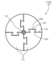
図3は、蒸気弁の擦り合わせ治工具100の擦り合わせ治工具本体111がグリッド構造の場合の例を示す図4のIII-III矢視縦断面図、図4は、図3のIV-IV矢視縦断面図である。以下、構造、形状等の説明の際の便宜上、蒸気弁の擦り合わせ治工具100を蒸気弁に搭載した状態を念頭に置いて、水平あるいは鉛直の用語を用いる場合があるが、蒸気弁の擦り合わせ治工具100あるいはそのための造形物の設置状態等を限定するものではない。
Figure 3 is a vertical cross-sectional view taken along the line III-III in Figure 4, showing an example in which the grinding
図3および図4で示すグリッド構造の擦り合わせ治工具110の場合は、擦り合わせ治工具本体111は、中空であり、その周方向の外壁と同心に形成された周方向強化板111f、軸挿入孔111p部分の中心壁111qから径方向外側に延びた径方向強化板111g、および治工具本体111内の空間を軸方向に区切るように配された軸方向区画板111hを有し、これらにより内部の空間が仕切られている。
In the case of the grinding
なお、弁座擦り合わせ治工具本体111は、さらに、キュービック構造としてもよい。
The valve seat
図5は、蒸気弁の擦り合わせ治工具100の擦り合わせ治工具本体111aがキュービック構造の場合の例を示す図6のV-V矢視縦断面図、図6は、図5のVI-VI矢視縦断面図である。擦り合わせ治工具本体111aは、中空であり、キュービック区画板111kにより内部が区分され、それぞれに立方体形状の空間が形成されている。
Figure 5 is a vertical cross-sectional view taken along the line V-V in Figure 6, showing an example in which the grinding
すなわち、キュービック区画板111kは、互いに間隔を置いて平行に配され鉛直方向に延びた第1の区画板と、互いに間隔を置いて平行に配され鉛直方向に延び第1の区画板に垂直に配された第2の区画板と、互いに間隔を置いて平行に配され水平方向に広がった第3の区画板とを有する。
That is, the
なお、キュービック区画板111kは、第1ないし第3の区画板の相互の関係が保持されていれば、全体としてたとえば第3の区画板が水平方向に向く場合に限定されない。すなわち、全体としては、任意の姿勢を有する場合であってもよい。
The
弁座擦り合わせ治工具本体111、111aの材料としては、たとえば、アクリロニトリル(Acrylonitrile)、ブタジエン(Butadi ene)、スチレン(Styrene)の共重合合成樹脂であるABS樹脂、あるいは、PLA(ポリ乳酸:Poluactic Acid)樹脂などの熱可塑性樹脂が用いられている。
The material used for the valve seat
軸112は、弁座擦り合わせ治工具本体111の回転中心と軸中心が一致するように、弁座擦り合わせ治工具本体111に形成された軸挿入孔111pを貫通している。軸112は、弁座擦り合わせ治工具本体111の上下にそれぞれ配されたナット115aおよびナット115bに締め付けられることにより弁座擦り合わせ治工具本体111に固定されている。なお、軸112を回転させる際に軸112と弁座擦り合わせ治工具本体111との間に滑りが生じないように、軸112と軸挿入孔111pとに互いに嵌合可能な凹凸部を形成してもよい。
The
軸112の弁座擦り合わせ治工具本体111への貫通側とは反対側の端部には、ハンドル113が固定して取り付けられており、ハンドル113により、弁座擦り合わせ治工具本体111を軸周りに回転操作可能となっている。
A
なお、例えば弁口径の小さな蒸気弁では、弁座擦り合わせ治工具110の重量が軽いことから、弁座擦り合わせ治工具110を弁座の上に搭載した場合に、弁座擦り合わせ部に十分な面圧が発生しない場合がある。このような場合には、弁座擦り合わせ治工具110は、図2に示すように、たとえば約10~20kg程度の環状の錘114を有して、これを弁座擦り合わせ治工具本体111の上面に搭載してもよい。なお、錘114は、環状でなく、たとえば、重さの等しい複数の部材が周方向に等間隔に配されていてもよい。
For example, in the case of a steam valve with a small valve diameter, the weight of the valve
弁座擦り合わせ治工具110は、弁座擦り合わせ治工具110を主蒸気止め弁弁座15上に搭載する際に、弁座擦り合わせ部111sと主蒸気止め弁弁座15との間に設置されるペーパー116を有する。ペーパー116は、擦り合わせ作業に際して、ペーパー116と主蒸気止め弁弁座15とを密着させて作業効率を向上させる目的で用いられる。ここで、ペーパー116は、材料はたとえば布ペーパーなどであり、0.5mm~1.0mm程度の厚みを有する。
The valve
次に、弁座擦り合わせ治工具本体111の製造方法およびこれを用いた弁座擦り合わせ方法について説明する。
Next, we will explain the manufacturing method of the valve seat
図7は、第1の実施形態に係る蒸気弁の擦り合わせ治工具の製造方法の手順およびその後のステップを示すフロー図である。弁座擦り合わせ治工具の製造ステップS10の後に、弁座擦り合わせステップS20、および全面シート当たり検査ステップS30が実施される。 Figure 7 is a flow diagram showing the procedure and subsequent steps of the method for manufacturing a grinding tool for a steam valve according to the first embodiment. After manufacturing step S10 of the valve seat grinding tool, step S20 of grinding the valve seat and step S30 of inspecting the entire sheet are performed.
まず、弁座擦り合わせ治工具本体111の製造方法について説明する。
First, we will explain the manufacturing method for the valve seat
弁座擦り合わせ治工具本体111は、以下のように、熱溶解積層方式3D(3次元)プリンターを用いて製造される。
The valve seat
まず、材料の選定を行う(ステップS01)。材料としては、熱可塑性樹脂を用いる。熱可塑性樹脂は、金属に比べ弾性率が小さく、木材と同等の弾性率である。熱可塑性樹脂としては、熱溶解積層方式3Dプリンターにおける造形ヘッドの溶融温度で溶融しうるものであれば用いることができ、融点が約230℃ 以下のものがよい。 First, a material is selected (step S01). Thermoplastic resin is used as the material. Thermoplastic resin has a smaller elastic modulus than metal, and an elastic modulus equivalent to that of wood. Any thermoplastic resin that can melt at the melting temperature of the modeling head of a fused deposition modeling 3D printer can be used, and a melting point of approximately 230°C or less is preferable.
熱可塑性樹脂により構成される造形材料の形態は3Dプリンターに装着できるものであれば限定しないが、連続線状に成形されたものとする。例えば、直径1.75mm~3.00mmの線状体、いわゆるモノフィラメント糸の形態を呈する成形体がよい。連続線状であるモノフィラメント糸の形態を呈する成形体は、ボビンに巻いた状態、あるいは、かせ状とすることにより、コンパクトな形態とすることができる。 The shape of the modeling material made of thermoplastic resin is not limited as long as it can be attached to a 3D printer, but it should be molded into a continuous line. For example, a linear body with a diameter of 1.75 mm to 3.00 mm, a molded body in the form of a monofilament thread, is preferable. A molded body in the form of a continuous linear monofilament thread can be made compact by winding it around a bobbin or forming it into a skein.
熱溶解積層方式3Dプリンター用造形材料として特に限定しないが、熱溶解積層方式3Dプリンターの仕様、特に、造形ヘッドの溶融温度を考慮して、ABS樹脂、ポリカーボネート、ポリアミド、PLA樹脂を好ましく用いる。なかでも、特にPLA樹脂を好ましく用いる。 There are no particular limitations on the modeling materials used in fused deposition modeling 3D printers, but ABS resin, polycarbonate, polyamide, and PLA resin are preferably used, taking into consideration the specifications of the fused deposition modeling 3D printer, and in particular the melting temperature of the modeling head. Of these, PLA resin is particularly preferred.
造形材料にPLA樹脂を採用した場合、約100℃にてアニール処理をすることにより内部応力を緩和することができ、作業中の衝撃荷重による割れの発生を抑制することができる。なお、3Dプリンターによる造形に際しては、アニール処理の実施による造形物の収縮分を考慮して3Dの寸法条件を設定する。このため、造形材料、製造条件ごとの収縮率データを、あらかじめ、作成あるいは入手し保有しておいてもよい。 When PLA resin is used as the modeling material, internal stress can be alleviated by annealing at approximately 100°C, and cracks caused by impact loads during operation can be prevented. When modeling using a 3D printer, the 3D dimensional conditions are set taking into account the shrinkage of the model caused by the annealing process. For this reason, shrinkage rate data for each modeling material and manufacturing conditions can be created or obtained in advance and stored.
なお、擦り合わせ作業中に衝撃荷重が負荷された場合での、その荷重に耐える強度を有するように、弁座擦り合わせ治工具本体111の内部充填率を、所定の値以上たとえば20%以上、かつ所定の値以下たとえば80%以下に設定する。なお、内部充填率の上限は、取り扱い上、60%以下が好ましい。ここで、弁座擦り合わせ治工具本体111の内部充填率rは、以下のように求めた値であるとする。
The internal filling rate of the valve seat
内部充填率r=(Vt-Vc)/Vc ・・・(1) Internal filling rate r=(Vt-Vc)/Vc...(1)
ただし、Vtは弁座擦り合わせ治工具本体111の外表面に囲まれた範囲の体積、Vcは内部に形成された空間の体積である。
where Vt is the volume of the area surrounded by the outer surface of the valve seat
内部充填率rが20%以下の場合は、内部強度が小さくなり作業中に擦り合わせ治工具の上に足や物などがのった場合には擦り合わせ治工具が破損するという問題がある。また、内部充填率rが60%以上の場合は、製造時間が長くなりまた製品の硬化による割れなどが発生しやすくなるという問題がある。特に、内部充填率rが80%以上の場合は、作業中の衝撃荷重による割れの発生を抑制するために、弁座擦り合わせ治工具ではアニール処理が必要になる可能性がある。 If the internal filling rate r is 20% or less, the internal strength is reduced, and if a foot or object is placed on the grinding tool during operation, the grinding tool may be damaged. If the internal filling rate r is 60% or more, the manufacturing time increases and the product becomes more susceptible to cracks due to hardening. In particular, if the internal filling rate r is 80% or more, annealing may be necessary for the valve seat grinding tool to prevent cracks from occurring due to impact loads during operation.
次に、熱溶解積層方式3Dプリンターを用いた製造に当たって、指定する製造条件、すなわち、内部充填率(インフィル密度)、グリッド構造、あるいは、キュービック構造となる内部充填構造、製造プロセス中の造形物の収縮率を考慮した各部寸法を設定する(ステップS02)。収縮率については、前述の収縮率のデータを活用する。 Next, when manufacturing using a fused deposition modeling 3D printer, the manufacturing conditions to be specified, i.e., the internal filling rate (infill density), the grid structure or the internal filling structure that will be a cubic structure, and the dimensions of each part are set taking into account the shrinkage rate of the object during the manufacturing process (step S02). The shrinkage rate data mentioned above is used to determine the shrinkage rate.
ここで、設定された寸法は、3Dデータとして構成される。さらに、高さ方向の高さ幅Δhを設定し、3Dデータに基づいて高さ幅Δhごとに切断した各面(積層面)の形状を算出する。 Here, the set dimensions are configured as 3D data. Furthermore, a height width Δh in the height direction is set, and the shape of each surface (layer surface) cut for each height width Δh is calculated based on the 3D data.
次に、熱溶解積層方式3Dプリンターを用いた造形を実施する(ステップS03)。 Next, modeling is carried out using a fused deposition modeling 3D printer (step S03).
図8は、熱溶解積層方式3Dプリンターによる造形ステップ中における造形物の状態を示す図9のVIII-VIII線矢視縦断面図、図9は、図8のIX-IX線矢視縦断面図である。 Figure 8 is a vertical cross-sectional view taken along line VIII-VIII in Figure 9, showing the state of the model during the modeling step using a fused deposition modeling 3D printer, and Figure 9 is a vertical cross-sectional view taken along line IX-IX in Figure 8.
ヒートベッド50の上面に、高さ幅Δhずつ、その積層面111t上に、熱溶解積層方式3Dプリンター用造形材料を積層する。この結果、造形物111zが、順次、高さ方向に造形されていく。
The fused deposition modeling 3D printer modeling material is layered on the
次に、熱溶解積層方式3Dプリンターにより製造された、弁座擦り合わせ治工具本体111のための造形物111zの内部充填率が80%程度以上の場合には、アニール処理を行う(ステップS04)。
Next, if the internal filling rate of the molded
たとえば、PLA樹脂の場合、内部充填率が70%程度以上の場合には、約100℃にて10分間程度アニール処理することにより、造形物の延性を高めることができる。 For example, in the case of PLA resin, if the internal filling rate is about 70% or more, the ductility of the molded object can be increased by annealing it at about 100°C for about 10 minutes.
次に、アニール処理後の弁座擦り合わせ治工具本体111のための造形物の最終寸法を測定し、必要な部分の修正加工を行う(ステップS05)。
Next, the final dimensions of the object for the valve seat
以上のステップS01ないしステップS05に並行して、弁座擦り合わせ治工具110の弁座擦り合わせ治工具本体111以外の部分、すなわち、軸112、ハンドル113、錘114、ナット115a、115b等を製作する(ステップS06)。
In parallel with steps S01 to S05 above, the parts of the valve
次に、以上のようにして製造された弁座擦り合わせ治工具本体111と、その他の部分、すなわち、軸112、ハンドル113、錘114等から、弁座擦り合わせ治工具110を組み立て、完成させる(ステップS07)。
Next, the valve seat
以上のように、ステップS01ないしS07により製作された弁座擦り合わせ治工具110は、以下のように弁座擦り合わせ作業に使用される。
As described above, the valve
次に、弁座擦り合わせ治工具本体111を用いた弁座擦り合わせ方法について説明する。
Next, we will explain the valve seat grinding method using the valve seat
図10は、蒸気弁の擦り合わせ治工具100による弁座擦り合わせ方法(ステップS20)の手順を示すフロー図である。
Figure 10 is a flow diagram showing the procedure for the valve seat grinding method (step S20) using the steam
まず、ペーパー116を弁座擦り合わせ治工具本体111の弁座擦り合わせ部111sに固定する(ステップS21)。固定には、たとえば、両面テープあるいは接着剤を用いることができる。
First, the
次に、弁座擦り合わせ治工具110を主蒸気止め弁10の主蒸気止め弁弁座15の上に搭載する(ステップS22)。
Next, the valve
次に、弁座擦り合わせ治工具110の弁座擦り合わせ治工具本体111の上面の上に、必要に応じて、錘114を搭載する(ステップS23)。
Next, if necessary, a
次に、弁座擦り合わせ治工具110のハンドル113で弁座擦り合わせ治工具本体111を回転させ、擦り合わせ作業を実施する(ステップS24)。
Next, the valve seat
弁座擦り合わせステップS20が終了したら、次に、全面シート当たり検査を実施する(ステップS30)。すなわち、弁座擦り合わせ治工具110を主蒸気止め弁10の主蒸気止め弁弁座15の上から取り外し、主蒸気止め弁10の主蒸気止め弁主弁11を搭載し、全面シート当たりが確保されていることを確認する。具体的には、例えは、主蒸気止め弁主弁11に光明丹などの塗布し、弁座15に押し付けることにより当たり面の有無を確認できる。
After the valve seat grinding step S20 is completed, a full-surface seat contact inspection is then performed (step S30). That is, the valve
以上のように製造された本実施形態による弁座擦り合わせ治工具110は、弁座擦り合わせ治工具本体111が、グリッド構造あるいはキュービック構造であり、かつ、内部充填率が所定の値以上であることから、擦り合わせ作業中の衝撃荷重に対しても強度を有する。
The valve
また、弁座擦り合わせ治工具本体111は、熱可塑性樹脂製であり、かつ、グリッド構造あるいはキュービック構造であることから、弁座擦り合わせ部111sが、たとえば主蒸気止め弁弁座15などの対象部分と、より広い範囲で密着するように弾性変形することにより、擦り合わせの効率向上を図ることができる。
In addition, since the valve seat
また、弁座擦り合わせ治工具本体111が軽量化され、作業中の取り扱いにクレーン等の揚重機を使用しなくてもよくなり、作業性の向上を図ることができる。
In addition, the valve seat
以上のように、本実施形態によれば、発電設備における蒸気弁の擦り合わせ作業のための適切な形状と強度を有する擦り合わせ治工具により定期点検時における作業効率を向上させることができる。 As described above, according to this embodiment, the grinding tool has an appropriate shape and strength for grinding the steam valves in the power generation facility, which can improve the work efficiency during regular inspections.
[第2の実施形態]
図11は、第2の実施形態に係る蒸気弁の弁座擦り合わせ治工具110aの構成を示す横断面図である。
Second Embodiment
FIG. 11 is a cross-sectional view showing the configuration of a valve
例えば再熱蒸気弁のように弁口径が大きな蒸気弁についての弁座擦り合わせ治工具は、熱溶解積層方式3Dプリンター設備の許容最大造形サイズを超え、一体で製造することができない場合がある。 For example, a valve seat grinding tool for a steam valve with a large valve diameter, such as a reheat steam valve, exceeds the maximum allowable modeling size of a fused deposition modeling 3D printer and may not be able to be manufactured as a single piece.
本実施形態による弁座擦り合わせ治工具110aは、円周方向に3分割あるいはそれ以上に分割し、それぞれの分割体を製造した上で、組木方式による組み合わせにより擦り合わせ治工具を製造するものである。それ以外は、第1の実施形態と同様である。
The valve
2分割の場合は、一体型の場合も2分割の場合も、最大長さは、いずれも直径であり、2分割しても最大長さは変わらない。3分割以上の分割とすることにより、最大長さが減少する。同様の理由で、同じ分割数であれば、等分割が好ましい。 In the case of two divisions, whether one piece or two divisions, the maximum length is the diameter, and the maximum length does not change even if it is divided into two. Dividing it into three or more divisions reduces the maximum length. For the same reason, if the number of divisions is the same, equal divisions are preferable.
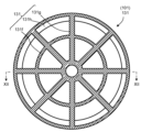
図11は、弁座擦り合わせ治工具110aの本体部である組み合わせ本体120を4分割方式とし、上面から見た概略図である。組合せにて組み合わせ本体120を製造する場合には、組木コーナー部122aを角部ではなく曲率を有するR形状とし、図11に示す組木面122bのギャップを組合せ面123のギャップより大きくすることにより、組み合わせ部分に応力集中が働かないようにする。
Figure 11 is a schematic diagram of the assembled
また、内部構造をグリッド構造もしくはキュービック構造としていることから、内部充填率を5%程度まで下げても、擦り合わせ作業時におけるシート部からの衝撃荷重に耐えることができる。これは、組木部がスポークとなり、擦り合わせ作業時におけるモーメントの大部分を主にスポーク部で伝えることができるためであり、また、分割することにより、組木部のスポークが梁となり、内部強度が大きくなることから、内部充填率を5%程度まで下げることができる。 In addition, because the internal structure is a grid or cubic structure, it can withstand the impact load from the sheet section during the rub-fitting process even if the internal filling rate is reduced to around 5%. This is because the joinery section acts as spokes, and most of the moment during the rub-fitting process can be transmitted mainly by the spokes. Also, by dividing it, the spokes of the joinery section act as beams, which increases the internal strength, making it possible to reduce the internal filling rate to around 5%.
以上のように、本実施形態に係る弁座擦り合わせ治工具110aにより、例えば、再熱弁のような口径の大きな蒸気弁では、従来の木製で製造した擦り合わせ治工具に比べ、約半分の重量にすることができる。この結果、天井クレーン等を使用せずに擦り合わせ治工具を設置することができる等により、作業性を向上させることができる。
As described above, the valve
[第3の実施形態]
図12は、第3の実施形態に係る蒸気弁の擦り合わせ治工具の製造方法におけるダレの除去ステップでの除去前を示す縦断面図、図13は、除去後を示す縦断面図である。
[Third embodiment]
FIG. 12 is a vertical cross-sectional view showing the state before removal in the sag removing step in the manufacturing method for the lapping jig tool for a steam valve according to the third embodiment, and FIG. 13 is a vertical cross-sectional view showing the state after removal.
熱溶解積層方式3Dプリンターを用いて弁座擦り合わせ治工具本体111を製造する場合に、前述の第1の実施形態におけるステップS03(図7)の熱溶解積層方式3Dプリンターによる造形において、本実施形態が適用される。すなわち、図12に示すように、造形物111zが、造形中にヒートベッド50から剥がれたり、反らないようにすることを目的に、ヒートベッド50の温度を約60℃に保持する。この温度が、造形物111zの材料のガラス転移温度よりも高い場合には、造形物111zが軟化する。この結果、造形中に造形物111zの自重などによりヒートベッド50近傍の底面にダレ111xが発生する。
When manufacturing the valve seat
対象とする蒸気弁の弁口径が小さく、分割タイプではなく、一体型で弁座擦り合わせ治工具本体111を製造する際には、このダレ111xは、蒸気弁の擦り合わせ時に蒸気弁内部構造物と干渉しなければ特に問題になることはない。
When the valve diameter of the steam valve in question is small and the valve seat
しかしながら、再熱弁のような大口径の擦り合わせ治工具100のように、組合せ方式により製造する場合、このダレ111xは、ヤスリなどにて除去する必要があり、さらに、材料にPLAを採用している場合には、除去中に割れる可能性がある。
However, when manufacturing a large-
そこで、ヒートベッド50近傍の、弁座擦り合わせ治工具本体111の底面に、面取り111yを施すことにより、造形中のダレ111xを解消させ、造形後の手入れ作業を短縮することができる。
Therefore, by applying
[第4の実施形態]
図14は、第4の実施形態に係る蒸気弁の擦り合わせ治工具の構成を示す図15のXII-XII線矢視縦断面図、図15は、図14のXIII-XIII線矢視水平断面図である。
[Fourth embodiment]
14 is a vertical cross-sectional view taken along line XII-XII in FIG. 15 showing the configuration of a grinding tool for a steam valve according to the fourth embodiment, and FIG. 15 is a horizontal cross-sectional view taken along line XIII-XIII in FIG.
前述のように、蒸気弁の擦り合わせ治工具100としては、蒸気弁の弁座の擦り合わせ治工具110と、蒸気弁の主弁(弁体)の擦り合わせ治工具130とが考えられる。
As mentioned above, the steam
第1ないし第3の実施形態では、前者の蒸気弁の弁座の擦り合わせ治工具110の場合を例にとって示した。本実施形態は、後者の蒸気弁の主弁の擦り合わせ治工具130の場合を例にとって示す。すなわち、本第4の実施形態は、第1の実施形態の変形であり、弁座の擦り合わせに代えて、例えば主蒸気止め弁10の主蒸気止め弁主弁11などの主弁の擦り合わせに用いるものである。
In the first to third embodiments, the former steam valve valve
一般的に、主弁側は、定期点検時にシート部当たりが悪い場合には、機械加工することが一般的である。しかしながら、機械加工によらず、擦り合わせを行うことにより、シート部当たりを改善できる場合もあることから、本実施形態による主弁擦り合わせ治工具130を用いることができ、その他の点では、第1の実施形態と同様である。
Generally, if the seat contact is poor during regular inspections, the main valve is generally machined. However, since it is sometimes possible to improve the seat contact by grinding instead of machining, the main
蒸気弁の擦り合わせ治工具100としての主弁擦り合わせ治工具130は、図14に示すように、対象とする主弁(弁体)、たとえば主蒸気止め弁主弁11の形状にフィットするような形状の凹部である主弁擦り合わせ部131sが中央に形成された擦り合わせ治工具本体101としての主弁擦り合わせ治工具本体131、および錘132を有する。
As shown in FIG. 14, the main
主弁擦り合わせ治工具本体131は、グリッド構造の場合を例にとって示しており、中空であり、内部に、周方向強化板131f、径方向強化板131g、および軸方向区画板131hを有し、これらにより構造強度を確保している。主弁11の弁座に対向する部分にフィットするように主弁擦り合わせ部131sが形成されている。
The main valve grinding
主弁擦り合わせ治工具130を用いる場合は、主弁擦り合わせ部131sにペーパー133を固定し、その側を鉛直上向きにした状態で、主弁擦り合わせ治工具130を、主弁擦り合わせ部131sが蒸気止め弁主弁11にフィットするように、蒸気止め弁主弁11上に搭載する。この際、必要に応じて、錘132を搭載する。この状態で、蒸気止め弁主弁11の側面をガイドとして主弁擦り合わせ治工具130を回転させることによりシート部の手入れをすることができる。
When using the main
このようにして、機械加工を施すことなく、擦り合わせのみでシート部当たりを改善することができる。 In this way, the seat contact can be improved by simply grinding, without the need for machining.
なお、以上の形態は、蒸気弁内の金属当たりの手入れを目的とした擦り合わせ治工具にも適用することができる。 The above configuration can also be applied to a grinding tool for the purpose of maintaining metal contact inside a steam valve.
[その他の実施形態]
以上、本発明の実施形態を説明したが、実施形態は、例として提示したものであり、発明の範囲を限定することは意図していない。
[Other embodiments]
Although the embodiments of the present invention have been described above, the embodiments have been presented as examples and are not intended to limit the scope of the invention.
また、各実施形態の特徴を組み合わせてもよい。また、実施形態は、その他の様々な形態で実施されることが可能であり、発明の要旨を逸脱しない範囲で、種々の省略、置き換え、変更を行うことができる。 Functions of each embodiment may be combined. The embodiments may also be implemented in various other forms, and various omissions, substitutions, and modifications may be made without departing from the spirit of the invention.
実施形態やその変形は、発明の範囲や要旨に含まれると同様に、特許請求の範囲に記載された発明とその均等の範囲に含まれるものである。 Embodiments and variations thereof are within the scope and spirit of the invention, as well as within the scope of the invention and its equivalents as described in the claims.
5…弁ケーシング、10…主蒸気止め弁、11…主蒸気止め弁主弁、12…主蒸気止め弁弁棒、13…主蒸気止め弁ヨーク、14…案内片、15…主蒸気止め弁弁座、16…主蒸気止め弁ケーシング部、16a…主蒸気止め弁入口、16b…主蒸気止め弁出口、17…ストレーナ、18…弁蓋、19…弁室、20…蒸気加減弁、21…蒸気加減弁主弁、22…蒸気加減弁弁棒、23…蒸気加減弁ヨーク、25…蒸気加減弁弁座、26…蒸気加減弁ケーシング部、26a…蒸気加減弁入口、26b…蒸気加減弁出口、27…弁蓋、29…弁室、30…接続部、50…ヒートベッド、100…擦り合わせ治工具、101、101a…擦り合わせ治工具本体、110、110a…弁座擦り合わせ治工具、111、111a…弁座擦り合わせ治工具本体、111c…円板部、111d…突出部、111f…周方向強化板、111g…径方向強化板、111h…軸方向区画板、111k…キュービック区画板、111p…軸挿入孔、111q…中心壁、111s…弁座擦り合わせ部、111x…ダレ、111y…面取り、111z…造形物、112…軸、113…ハンドル、114…錘、115a、115b…ナット、116…ペーパー、120…組み合わせ本体、121…分割体、122…組木部、122a…組木コーナー部、122b…組木面、123…組み合わせ面、130…主弁擦り合わせ治工具、131…主弁擦り合わせ治工具本体、131f…周方向強化板、131g…径方向強化板、131h…軸方向区画板、131s…主弁擦り合わせ部、132…錘、133…ペーパー 5...valve casing, 10...main steam stop valve, 11...main steam stop valve main valve, 12...main steam stop valve stem, 13...main steam stop valve yoke, 14...guide piece, 15...main steam stop valve seat, 16...main steam stop valve casing part, 16a...main steam stop valve inlet, 16b...main steam stop valve outlet, 17...strainer, 18...valve cover, 19...valve chamber, 20...steam control valve, 21...steam control valve main valve, 22...steam control valve Valve stem, 23... steam regulating valve yoke, 25... steam regulating valve seat, 26... steam regulating valve casing part, 26a... steam regulating valve inlet, 26b... steam regulating valve outlet, 27... valve cover, 29... valve chamber, 30... connection part, 50... heat bed, 100... grinding tool, 101, 101a... grinding tool main body, 110, 110a... valve seat grinding tool, 111, 111a... valve seat grinding tool Main body, 111c...disk portion, 111d...protruding portion, 111f...circumferential strengthening plate, 111g...radial strengthening plate, 111h...axial partition plate, 111k...cubic partition plate, 111p...shaft insertion hole, 111q...center wall, 111s...valve seat grinding portion, 111x...sag, 111y...chamfer, 111z...molded object, 112...shaft, 113...handle, 114...weight, 115a, 115b...nut, 116...paper, 120...combined body, 121...divided body, 122...joint part, 122a...joint corner part, 122b...joint surface, 123...combined surface, 130...main valve grinding tool, 131...main valve grinding tool body, 131f...circumferential reinforcement plate, 131g...radial reinforcement plate, 131h...axial partition plate, 131s...main valve grinding part, 132...weight, 133...paper
Claims (5)
中心軸周りに回転対称な形状であって前記擦り合わせ対象部分に密着可能な部分が周方向にわたって形成された擦り合わせ治工具本体を備え、
前記擦り合わせ治工具本体は、
熱可塑性樹脂を材料とし、
内部構造がグリッド構造またはキュービック構造であり、内部充填率が20%以上で60%以下である、
ことを特徴とする蒸気弁の擦り合わせ治工具。 A steam valve rubbing tool used for rubbing a valve seat or a main valve of a steam valve, comprising:
A rubbing tool body having a rotationally symmetric shape about a central axis and a portion capable of being brought into close contact with the rubbing target portion is formed in a circumferential direction,
The rubbing tool body is
Made of thermoplastic resin,
The internal structure is a grid structure or a cubic structure, and the internal filling rate is 20% or more and 60% or less .
A steam valve grinding tool characterized by the above.
選定された熱可塑性樹脂を用いて、前記熱溶解積層方式3Dプリンターにより造形物を生成する造形ステップと、
を有することを特徴とする蒸気弁の弁座擦り合わせ治工具製造方法。 A setting step of setting the internal structure of a grinding tool body used for grinding the valve seat of a steam valve in a fused deposition model 3D printer to be a grid structure or a cubic structure, and setting the internal filling rate to be 20% or more and 60% or less;
A modeling step of generating a modeled object by the fused deposition modeling 3D printer using the selected thermoplastic resin;
1. A method for manufacturing a steam valve seat grinding tool , comprising the steps of:
The method for manufacturing a steam valve seat grinding tool as described in claim 4 , characterized in that the molding step includes a step of removing sagging at the bottom of the object molded on the heat bed of the fused deposition model 3D printer .
Priority Applications (1)
| Application Number | Priority Date | Filing Date | Title |
|---|---|---|---|
| JP2020091261A JP7516111B2 (en) | 2020-05-26 | 2020-05-26 | Steam valve grinding tool and method for manufacturing steam valve seat grinding tool |
Applications Claiming Priority (1)
| Application Number | Priority Date | Filing Date | Title |
|---|---|---|---|
| JP2020091261A JP7516111B2 (en) | 2020-05-26 | 2020-05-26 | Steam valve grinding tool and method for manufacturing steam valve seat grinding tool |
Publications (2)
| Publication Number | Publication Date |
|---|---|
| JP2021186892A JP2021186892A (en) | 2021-12-13 |
| JP7516111B2 true JP7516111B2 (en) | 2024-07-16 |
Family
ID=78847948
Family Applications (1)
| Application Number | Title | Priority Date | Filing Date |
|---|---|---|---|
| JP2020091261A Active JP7516111B2 (en) | 2020-05-26 | 2020-05-26 | Steam valve grinding tool and method for manufacturing steam valve seat grinding tool |
Country Status (1)
| Country | Link |
|---|---|
| JP (1) | JP7516111B2 (en) |
Citations (5)
| Publication number | Priority date | Publication date | Assignee | Title |
|---|---|---|---|---|
| JP2015093461A (en) | 2013-11-13 | 2015-05-18 | 株式会社東芝 | Three-dimensional structure component |
| JP2016020401A (en) | 2014-07-11 | 2016-02-04 | ユニチカ株式会社 | Molding material |
| US20190299342A1 (en) | 2016-05-10 | 2019-10-03 | Fisher Controls International Llc | Late Customization on Valve Body End Connections Using Additive Manufacturing |
| WO2019229610A1 (en) | 2018-05-30 | 2019-12-05 | 3M Innovative Properties Company | Abrasive rotary tool |
| JP2020062776A (en) | 2018-10-16 | 2020-04-23 | 本田技研工業株式会社 | Manufacturing apparatus of three-dimensional shaped article, manufacturing method of three-dimensional shaped article, and three-dimensional shaped article |
Family Cites Families (3)
| Publication number | Priority date | Publication date | Assignee | Title |
|---|---|---|---|---|
| JPS52104187U (en) * | 1976-02-05 | 1977-08-08 | ||
| JPS6131651U (en) * | 1984-07-27 | 1986-02-26 | 三菱重工業株式会社 | Jig for correcting the valve seat of a steam control valve |
| JP2808357B2 (en) * | 1990-10-08 | 1998-10-08 | 中部電力株式会社 | Sliding device for valve body and valve seat |
-
2020
- 2020-05-26 JP JP2020091261A patent/JP7516111B2/en active Active
Patent Citations (6)
| Publication number | Priority date | Publication date | Assignee | Title |
|---|---|---|---|---|
| JP2015093461A (en) | 2013-11-13 | 2015-05-18 | 株式会社東芝 | Three-dimensional structure component |
| JP2016020401A (en) | 2014-07-11 | 2016-02-04 | ユニチカ株式会社 | Molding material |
| US20190299342A1 (en) | 2016-05-10 | 2019-10-03 | Fisher Controls International Llc | Late Customization on Valve Body End Connections Using Additive Manufacturing |
| WO2019229610A1 (en) | 2018-05-30 | 2019-12-05 | 3M Innovative Properties Company | Abrasive rotary tool |
| JP2021525656A (en) | 2018-05-30 | 2021-09-27 | スリーエム イノベイティブ プロパティズ カンパニー | Rotating tool for polishing |
| JP2020062776A (en) | 2018-10-16 | 2020-04-23 | 本田技研工業株式会社 | Manufacturing apparatus of three-dimensional shaped article, manufacturing method of three-dimensional shaped article, and three-dimensional shaped article |
Also Published As
| Publication number | Publication date |
|---|---|
| JP2021186892A (en) | 2021-12-13 |
Similar Documents
| Publication | Publication Date | Title |
|---|---|---|
| US9943932B2 (en) | Trunnion hole repair method utilizing interference fit inserts | |
| EP0855022B1 (en) | Methods for the design, quality control, and management of fatigue-limited metal components | |
| EP0376874A2 (en) | Fabrication or repair technique for integrally bladed rotor assembly | |
| JP3295470B2 (en) | Welding method for steam turbine rotor | |
| US7013551B2 (en) | Method or manufacturing thin wall isogrid casings | |
| JP7516111B2 (en) | Steam valve grinding tool and method for manufacturing steam valve seat grinding tool | |
| Coupek et al. | Proactive quality control system for defect reduction in the production of electric drives | |
| TW202335406A (en) | Stacked lamination endplate | |
| CN112792507B (en) | Preparation method of titanium alloy blisk | |
| DE69329546T2 (en) | DEVICE FOR REMOVING LOCKABLE MATERIAL FROM AIR SEALS IN NOZZLE ENGINES | |
| US2174380A (en) | Method of making elastic fluid turbines | |
| CN119289828A (en) | A method for measuring flow through assembly of thermal power steam turbine | |
| CN118682259A (en) | A processing method for multi-weld anti-deformation control cavity wall of aircraft engine coupling | |
| Barack et al. | An improved turbine disk design to increase reliability of aircraft jet engines | |
| US20040226420A1 (en) | Production of disc components | |
| JPH0116620B2 (en) | ||
| US20260084243A1 (en) | Impeller for a flow machine and method for producing an impeller | |
| Feldhausen et al. | Hybrid Manufacturing Approaches for the Production and Repair of Industrial Tooling | |
| KR102702656B1 (en) | Method for welding bucket cover of turbine and Method for estimating repair reliability of rotational body structure | |
| CN113757167B (en) | A long-life control method for centrifugal impellers | |
| Pish et al. | Design and manufacture of robust composite flywheels for microgrids | |
| Menichino et al. | Impeller Manufacturing: Understanding the Methods and Their Impact on Performance | |
| US7524566B2 (en) | Composite material, method for the production of a composite material and the utilization thereof | |
| Scheidler et al. | Manufacturing of flux modulators for mass-optimized concentric magnetic gearing | |
| Finney et al. | Evaluation of Graphite/Epoxy Shims in a High Capacity Laminate Helicopter Bearing |
Legal Events
| Date | Code | Title | Description |
|---|---|---|---|
| A621 | Written request for application examination |
Free format text: JAPANESE INTERMEDIATE CODE: A621 Effective date: 20230125 |
|
| A977 | Report on retrieval |
Free format text: JAPANESE INTERMEDIATE CODE: A971007 Effective date: 20231130 |
|
| A131 | Notification of reasons for refusal |
Free format text: JAPANESE INTERMEDIATE CODE: A131 Effective date: 20231226 |
|
| A521 | Request for written amendment filed |
Free format text: JAPANESE INTERMEDIATE CODE: A523 Effective date: 20240220 |
|
| TRDD | Decision of grant or rejection written | ||
| A01 | Written decision to grant a patent or to grant a registration (utility model) |
Free format text: JAPANESE INTERMEDIATE CODE: A01 Effective date: 20240604 |
|
| A61 | First payment of annual fees (during grant procedure) |
Free format text: JAPANESE INTERMEDIATE CODE: A61 Effective date: 20240703 |
|
| R150 | Certificate of patent or registration of utility model |
Ref document number: 7516111 Country of ref document: JP Free format text: JAPANESE INTERMEDIATE CODE: R150 |