JP2021525656A - Rotating tool for polishing - Google Patents
Rotating tool for polishing Download PDFInfo
- Publication number
- JP2021525656A JP2021525656A JP2020566671A JP2020566671A JP2021525656A JP 2021525656 A JP2021525656 A JP 2021525656A JP 2020566671 A JP2020566671 A JP 2020566671A JP 2020566671 A JP2020566671 A JP 2020566671A JP 2021525656 A JP2021525656 A JP 2021525656A
- Authority
- JP
- Japan
- Prior art keywords
- polishing
- layer
- rotary tool
- assembly
- polishing assembly
- Prior art date
- Legal status (The legal status is an assumption and is not a legal conclusion. Google has not performed a legal analysis and makes no representation as to the accuracy of the status listed.)
- Withdrawn
Links
Images


Classifications
-
- B—PERFORMING OPERATIONS; TRANSPORTING
- B24—GRINDING; POLISHING
- B24D—TOOLS FOR GRINDING, BUFFING OR SHARPENING
- B24D3/00—Physical features of abrasive bodies, or sheets, e.g. abrasive surfaces of special nature; Abrasive bodies or sheets characterised by their constituents
- B24D3/001—Physical features of abrasive bodies, or sheets, e.g. abrasive surfaces of special nature; Abrasive bodies or sheets characterised by their constituents the constituent being used as supporting member
- B24D3/002—Flexible supporting members, e.g. paper, woven, plastic materials
-
- B—PERFORMING OPERATIONS; TRANSPORTING
- B24—GRINDING; POLISHING
- B24B—MACHINES, DEVICES, OR PROCESSES FOR GRINDING OR POLISHING; DRESSING OR CONDITIONING OF ABRADING SURFACES; FEEDING OF GRINDING, POLISHING, OR LAPPING AGENTS
- B24B45/00—Means for securing grinding wheels on rotary arbors
- B24B45/006—Quick mount and release means for disc-like wheels, e.g. on power tools
-
- B—PERFORMING OPERATIONS; TRANSPORTING
- B24—GRINDING; POLISHING
- B24B—MACHINES, DEVICES, OR PROCESSES FOR GRINDING OR POLISHING; DRESSING OR CONDITIONING OF ABRADING SURFACES; FEEDING OF GRINDING, POLISHING, OR LAPPING AGENTS
- B24B49/00—Measuring or gauging equipment for controlling the feed movement of the grinding tool or work; Arrangements of indicating or measuring equipment, e.g. for indicating the start of the grinding operation
- B24B49/16—Measuring or gauging equipment for controlling the feed movement of the grinding tool or work; Arrangements of indicating or measuring equipment, e.g. for indicating the start of the grinding operation taking regard of the load
-
- B—PERFORMING OPERATIONS; TRANSPORTING
- B24—GRINDING; POLISHING
- B24B—MACHINES, DEVICES, OR PROCESSES FOR GRINDING OR POLISHING; DRESSING OR CONDITIONING OF ABRADING SURFACES; FEEDING OF GRINDING, POLISHING, OR LAPPING AGENTS
- B24B51/00—Arrangements for automatic control of a series of individual steps in grinding a workpiece
-
- B—PERFORMING OPERATIONS; TRANSPORTING
- B24—GRINDING; POLISHING
- B24B—MACHINES, DEVICES, OR PROCESSES FOR GRINDING OR POLISHING; DRESSING OR CONDITIONING OF ABRADING SURFACES; FEEDING OF GRINDING, POLISHING, OR LAPPING AGENTS
- B24B9/00—Machines or devices designed for grinding edges or bevels on work or for removing burrs; Accessories therefor
- B24B9/02—Machines or devices designed for grinding edges or bevels on work or for removing burrs; Accessories therefor characterised by a special design with respect to properties of materials specific to articles to be ground
- B24B9/06—Machines or devices designed for grinding edges or bevels on work or for removing burrs; Accessories therefor characterised by a special design with respect to properties of materials specific to articles to be ground of non-metallic inorganic material, e.g. stone, ceramics, porcelain
- B24B9/08—Machines or devices designed for grinding edges or bevels on work or for removing burrs; Accessories therefor characterised by a special design with respect to properties of materials specific to articles to be ground of non-metallic inorganic material, e.g. stone, ceramics, porcelain of glass
-
- B—PERFORMING OPERATIONS; TRANSPORTING
- B24—GRINDING; POLISHING
- B24D—TOOLS FOR GRINDING, BUFFING OR SHARPENING
- B24D13/00—Wheels having flexibly-acting working parts, e.g. buffing wheels; Mountings therefor
- B24D13/02—Wheels having flexibly-acting working parts, e.g. buffing wheels; Mountings therefor acting by their periphery
-
- B—PERFORMING OPERATIONS; TRANSPORTING
- B24—GRINDING; POLISHING
- B24D—TOOLS FOR GRINDING, BUFFING OR SHARPENING
- B24D13/00—Wheels having flexibly-acting working parts, e.g. buffing wheels; Mountings therefor
- B24D13/14—Wheels having flexibly-acting working parts, e.g. buffing wheels; Mountings therefor acting by the front face
-
- B—PERFORMING OPERATIONS; TRANSPORTING
- B24—GRINDING; POLISHING
- B24D—TOOLS FOR GRINDING, BUFFING OR SHARPENING
- B24D13/00—Wheels having flexibly-acting working parts, e.g. buffing wheels; Mountings therefor
- B24D13/20—Mountings for the wheels
-
- B—PERFORMING OPERATIONS; TRANSPORTING
- B24—GRINDING; POLISHING
- B24D—TOOLS FOR GRINDING, BUFFING OR SHARPENING
- B24D18/00—Manufacture of grinding tools or other grinding devices, e.g. wheels, not otherwise provided for
- B24D18/0072—Manufacture of grinding tools or other grinding devices, e.g. wheels, not otherwise provided for using adhesives for bonding abrasive particles or grinding elements to a support, e.g. by gluing
-
- B—PERFORMING OPERATIONS; TRANSPORTING
- B24—GRINDING; POLISHING
- B24D—TOOLS FOR GRINDING, BUFFING OR SHARPENING
- B24D5/00—Bonded abrasive wheels, or wheels with inserted abrasive blocks, designed for acting only by their periphery; Bushings or mountings therefor
- B24D5/16—Bushings; Mountings
-
- B—PERFORMING OPERATIONS; TRANSPORTING
- B24—GRINDING; POLISHING
- B24D—TOOLS FOR GRINDING, BUFFING OR SHARPENING
- B24D7/00—Bonded abrasive wheels, or wheels with inserted abrasive blocks, designed for acting otherwise than only by their periphery, e.g. by the front face; Bushings or mountings therefor
- B24D7/16—Bushings; Mountings
-
- B—PERFORMING OPERATIONS; TRANSPORTING
- B24—GRINDING; POLISHING
- B24D—TOOLS FOR GRINDING, BUFFING OR SHARPENING
- B24D9/00—Wheels or drums supporting in exchangeable arrangement a layer of flexible abrasive material, e.g. sandpaper
- B24D9/08—Circular back-plates for carrying flexible material
- B24D9/085—Devices for mounting sheets on a backing plate
Landscapes
- Engineering & Computer Science (AREA)
- Mechanical Engineering (AREA)
- Manufacturing & Machinery (AREA)
- Chemical & Material Sciences (AREA)
- Ceramic Engineering (AREA)
- Inorganic Chemistry (AREA)
- Polishing Bodies And Polishing Tools (AREA)
- Grinding And Polishing Of Tertiary Curved Surfaces And Surfaces With Complex Shapes (AREA)
Abstract
本開示は、交換可能性及び向上した接触圧を有する研磨用回転工具を提供する。例示的な研磨用回転工具は、研磨アセンブリホルダ、研磨アセンブリ、及び弾性層を含む。研磨アセンブリは、基材の表面を研磨するための接触面を有する研磨層と、基材の表面に対する研磨中に、接触面を実質的に平坦に維持するように研磨層を支持する硬質支持層と、を含む。弾性層は、シャンクと研磨層との間に配置され、接触面の基材との接触時間を増加させるように、基材の研磨中に圧縮するように構成される。例示的な研磨用回転工具はまた、研磨アセンブリを研磨アセンブリホルダに取り付けるように構成された結合層を含む。研磨アセンブリは、十分な量摩耗すると、研磨アセンブリホルダから取り外され、別の研磨アセンブリと交換される。The present disclosure provides a rotary tool for polishing with replaceability and improved contact pressure. An exemplary polishing rotary tool includes a polishing assembly holder, a polishing assembly, and an elastic layer. The polishing assembly includes a polishing layer having a contact surface for polishing the surface of the substrate and a hard support layer that supports the polishing layer so as to keep the contact surface substantially flat during polishing against the surface of the substrate. And, including. The elastic layer is arranged between the shank and the polishing layer and is configured to compress during polishing of the substrate so as to increase the contact time of the contact surface with the substrate. An exemplary polishing rotary tool also includes a bonding layer configured to attach the polishing assembly to the polishing assembly holder. After a sufficient amount of wear, the polishing assembly is removed from the polishing assembly holder and replaced with another polishing assembly.
Description
本発明は、研磨用回転工具に関する。 The present invention relates to a rotary tool for polishing.
タッチスクリーンスマートフォン及びタブレットなどのハンドヘルド電子機器は、それらのデバイスに耐久性及び光学的透明度をもたらすカバーガラスを含むことが多い。カバーガラスの製造は、各カバーガラス内の特徴部の均質性及び大量生産のためにコンピュータ数値制御(CNC)機械加工を使用することがある。カバーガラスの周辺部のエッジ仕上げは、強度及び美的外観にとって重要である。典型的には、メタルボンドダイヤモンド工具などのダイヤモンド研磨工具を使用して、カバーガラスを機械加工する。これらの工具は、比較的長時間の耐久性を有し得るものであり、高い切断速度で有効であり得る。しかしながら、これらの工具は、カバーガラスに微小亀裂を残すことがあり、これが応力集中点となり、ガラスの強度を著しく低下させることがある。カバーガラスの強度又は外観を改善するために、エッジをポリッシングすることができる。例えば、酸化セリウムなどのポリッシングスラリーを典型的には使用して、ガラスカバーをポリッシングする。しかしながら、スラリー系ポリッシングは速度が遅く、複数のポリッシング工程を必要とすることがある。更に、スラリーポリッシング装置は、大型で、高価で、ポリッシングされる特定の特徴部に特有のものであり得る。全体的に見れば、スラリーポリッシングシステム自体が、歩留まりが低くなり、研磨される基材の丸みを帯びた角部を作成して、必要労働量が増加する恐れがある。 Handheld electronics such as touch screen smartphones and tablets often include a cover glass that provides durability and optical transparency to those devices. Cover glass manufacturing may use computer numerically controlled (CNC) machining for homogeneity and mass production of features within each cover glass. The edge finish around the cover glass is important for strength and aesthetic appearance. Typically, a diamond polishing tool, such as a metal bond diamond tool, is used to machine the cover glass. These tools can have a relatively long durability and can be effective at high cutting speeds. However, these tools can leave microcracks in the cover glass, which can become stress concentration points and significantly reduce the strength of the glass. Edges can be polished to improve the strength or appearance of the cover glass. For example, a polishing slurry such as cerium oxide is typically used to polish the glass cover. However, slurry-based polishing is slow and may require multiple polishing steps. In addition, slurry polishing equipment can be large, expensive and specific to the particular feature being polished. Overall, the slurry polishing system itself can reduce yields and create rounded corners of the substrate to be polished, increasing labor requirements.
本開示は、概して、基材への接触圧が改善された研磨用回転工具を対象とする。例示的な研磨用回転工具は、研磨アセンブリホルダ、研磨アセンブリ、及び弾性層を含む。研磨アセンブリは、剛性支持層及び研磨層を含む。研磨層は、基材の表面を研磨するように構成された接触面を有する。剛性支持層は、基材の表面に対する研磨中に、接触面が実質的に平坦なままであるように、研磨層を支持するように構成される。弾性層は、研磨アセンブリホルダのシャンクと研磨層との間、例えば、シャフトと剛性支持層との間に配置される。弾性層は、接触面と基材との接触時間が増加し得るように、基材の研磨中に圧縮するように構成される。研磨用回転工具は、研磨層の近位にある剛性支持層及び研磨層の遠位にある弾性層を使用しない研磨用回転工具と比較して、基材に対して方向的により均一な接触力を加えることができ、平面性の向上、除去速度の均一性の向上、及び/又は寿命の向上を伴う。例示的な研磨用回転工具はまた、研磨アセンブリを回転工具の研磨アセンブリホルダに取り付けるように構成された結合層を含む。研磨アセンブリは、十分な量摩耗すると、取り外され、別の研磨アセンブリと交換される。 The present disclosure is generally directed to rotary tools for polishing with improved contact pressure to the substrate. An exemplary polishing rotary tool includes a polishing assembly holder, a polishing assembly, and an elastic layer. The polishing assembly includes a rigid support layer and a polishing layer. The polishing layer has a contact surface configured to polish the surface of the substrate. The rigid support layer is configured to support the polished layer so that the contact surface remains substantially flat during polishing against the surface of the substrate. The elastic layer is arranged between the shank of the polishing assembly holder and the polishing layer, for example, between the shaft and the rigid support layer. The elastic layer is configured to compress during polishing of the substrate so that the contact time between the contact surface and the substrate can be increased. Polishing rotary tools do not use a rigid support layer proximal to the polishing layer and an elastic layer distal to the polishing layer. Can be added, with improved flatness, improved removal rate uniformity, and / or improved life. An exemplary polishing rotary tool also includes a bonding layer configured to attach the polishing assembly to the polishing assembly holder of the rotary tool. After a sufficient amount of wear, the polishing assembly is removed and replaced with another polishing assembly.
一実施形態では、研磨用回転工具は、研磨アセンブリホルダ、研磨アセンブリ、及び弾性層を含む。研磨アセンブリホルダは、回転工具の回転軸を画定するシャンクを含む。研磨アセンブリは、剛性支持層及び研磨層を含む。剛性支持層は、約90を超えるショアA硬度を有する。研磨層は、接触面を有する。弾性層は、シャンクと研磨層との間に配置されている。弾性層は、約70未満のショアA硬度を有する。 In one embodiment, the polishing rotary tool includes a polishing assembly holder, a polishing assembly, and an elastic layer. The polishing assembly holder includes a shank that defines the axis of rotation of the rotating tool. The polishing assembly includes a rigid support layer and a polishing layer. The rigid support layer has a Shore A hardness of more than about 90. The polishing layer has a contact surface. The elastic layer is arranged between the shank and the polishing layer. The elastic layer has a Shore A hardness of less than about 70.
別の実施形態では、研磨用回転工具は、研磨アセンブリホルダ、研磨アセンブリ、及び弾性層を含む。研磨アセンブリホルダは、回転工具の回転軸を画定するシャンクを含む。研磨アセンブリは、剛性支持層及び研磨層を含む。剛性支持層は、約1GPaを超える圧縮弾性率を有する。研磨層は、接触面を有する。弾性層は、シャンクと研磨層との間に配置されている。弾性層は、約0.1GPa未満の弾性率を有する。 In another embodiment, the polishing rotary tool includes a polishing assembly holder, a polishing assembly, and an elastic layer. The polishing assembly holder includes a shank that defines the axis of rotation of the rotating tool. The polishing assembly includes a rigid support layer and a polishing layer. The rigid support layer has a compressive modulus of more than about 1 GPa. The polishing layer has a contact surface. The elastic layer is arranged between the shank and the polishing layer. The elastic layer has an elastic modulus of less than about 0.1 GPa.
別の実施形態では、ポリッシングシステムは、研磨アセンブリホルダと、第1の研磨アセンブリと、結合層とを含む研磨用回転工具を含む。研磨アセンブリホルダは、回転工具の回転軸を画定するシャンクを含む。第1の研磨アセンブリは、研磨アセンブリホルダに結合され、第1の剛性支持層と、第1の接触面を有する第1の研磨層とを含む。結合層は、シャンクと研磨層との間に配置されている。ポリッシングシステムは、第2の剛性支持層と、第2の接触面を有する第2の研磨層と、を含む第2の研磨アセンブリを更に含む。ポリッシングシステムは、第1の研磨アセンブリを回転工具から取り外し、第2の研磨アセンブリを研磨アセンブリホルダに取り付けるように構成された回転工具交換装置を更に含む。 In another embodiment, the polishing system comprises a polishing rotary tool that includes a polishing assembly holder, a first polishing assembly, and a bonding layer. The polishing assembly holder includes a shank that defines the axis of rotation of the rotating tool. The first polishing assembly is coupled to the polishing assembly holder and includes a first rigid support layer and a first polishing layer having a first contact surface. The binding layer is arranged between the shank and the polishing layer. The polishing system further includes a second polishing assembly that includes a second rigid support layer and a second polishing layer having a second contact surface. The polishing system further includes a rotary tool changer configured to remove the first polishing assembly from the rotary tool and attach the second polishing assembly to the polishing assembly holder.
別の例では、アセンブリは、コンピュータ制御回転工具ホルダ及び基板プラットフォームを含むコンピュータ制御機械加工システムと、基板プラットフォームに固定された基板と、上述の研磨用回転工具とを含む。 In another example, the assembly includes a computer controlled machining system including a computer controlled rotary tool holder and a substrate platform, a substrate secured to the substrate platform, and the polishing rotary tool described above.
別の実施形態では、基材をポリッシングするための方法は、コンピュータ制御回転工具ホルダと基材プラットフォームとを含むコンピュータ制御機械加工システムを提供することを含む。本方法は、研磨用回転工具をコンピュータ制御機械加工システムの回転工具ホルダに固定することを更に含む。研磨用回転工具は、研磨アセンブリホルダ、第1の研磨アセンブリ、及び結合性層を含む。研磨アセンブリホルダは、回転工具の回転軸を画定するシャンクを含む。第1の研磨アセンブリは、研磨アセンブリホルダに結合され、第1の剛性支持層と、第1の接触面を有する第1の研磨層とを含む。結合層は、シャンクと研磨層との間に配置されている。本方法は、研磨用回転工具の第1の研磨アセンブリを使用して基板の接触面を研磨するように、コンピュータ制御機械加工システムを操作することを更に含む。本方法は、研磨用回転工具の研磨アセンブリホルダから第1の研磨アセンブリを取り外し、第2の研磨アセンブリを研磨用回転工具の研磨アセンブリホルダに取り付けることを更に含む。第2の研磨アセンブリは、第2の剛性支持層と、第2の接触面を有する第2の研磨層とを含む。 In another embodiment, the method for polishing the substrate comprises providing a computer controlled machining system that includes a computer controlled rotary tool holder and a substrate platform. The method further comprises fixing the polishing rotary tool to the rotary tool holder of a computer controlled machining system. The polishing rotary tool includes a polishing assembly holder, a first polishing assembly, and a binding layer. The polishing assembly holder includes a shank that defines the axis of rotation of the rotating tool. The first polishing assembly is coupled to the polishing assembly holder and includes a first rigid support layer and a first polishing layer having a first contact surface. The binding layer is arranged between the shank and the polishing layer. The method further comprises manipulating a computer-controlled machining system to grind the contact surfaces of the substrate using the first grind assembly of the grind rotary tool. The method further comprises removing the first polishing assembly from the polishing assembly holder of the rotating tool for polishing and attaching the second polishing assembly to the polishing assembly holder of the rotating tool for polishing. The second polishing assembly includes a second rigid support layer and a second polishing layer having a second contact surface.
本開示の1つ以上の実施形態の詳細は、添付の図面及び以下の説明で述べる。本発明のその他の特徴、目的、及び利点は、明細書及び図面、並びに特許請求の範囲から明らかになろう。 Details of one or more embodiments of the present disclosure will be given in the accompanying drawings and the following description. Other features, objectives, and advantages of the present invention will become apparent from the specification and drawings, as well as the claims.
図中の同様の符号は、同様の要素を示している。点線は任意選択的な又は機能的な構成要素を示し、破線は表示されていない構成要素を示す。 Similar reference numerals in the figure indicate similar elements. Dotted lines indicate optional or functional components, and dashed lines indicate undisplayed components.
本開示は、改善された基材形状をもたらす研磨物品について説明する。 The present disclosure describes a polished article that provides an improved substrate shape.
多くの場合、構成要素の特定の表面を研磨するために、研磨用回転工具を使用することができる。剛性研磨用回転工具は、回転工具の研磨層の接触面からの圧力の適用において高い変動を示す可能性があり、これは、構成要素の表面のばらつきによる構成要素の表面の均一性のない研磨を引き起こし得る。接触層と構成要素の表面との接触を改善するために、研磨層は、研磨層の接触面が構成要素の表面になじむことを可能にする圧縮可能バッキングを有してもよい。このようななじみ性は、丸みを帯びたエッジを提供するために望ましいかもしれないが、平坦なエッジを提供するためには望ましくない場合がある。例えば、接触面が、構成要素の表面の角部において、構成要素の表面よりも大きな圧力を加え、構成要素の非平坦な表面をもたらす恐れがある。 In many cases, a rotating tool for polishing can be used to polish a particular surface of a component. Rotating tools for rigid polishing can show high variation in the application of pressure from the contact surface of the polishing layer of the rotating tool, which is the uneven polishing of the surface of the component due to the surface variation of the component. Can cause. To improve contact between the contact layer and the surface of the component, the polishing layer may have a compressible backing that allows the contact surface of the polishing layer to adapt to the surface of the component. Such familiarity may be desirable to provide rounded edges, but may not be desirable to provide flat edges. For example, the contact surface may apply greater pressure at the corners of the component's surface than the component's surface, resulting in a non-flat surface of the component.
本明細書で説明されるように、本開示の研磨用回転工具は、基材の表面のより均一な平面性のために、基材の研磨中の接触が改善され、回転工具の接触面の摩耗がより少ない、平坦な接触面を提供することができる。一実施形態では、研磨用回転工具は、シャンク、研磨アセンブリ、及び弾性層を含む。研磨アセンブリは、研磨層及び剛性支持層を含む。研磨層は、基材に面で接触し、基材の表面から材料を除去するように構成されている。剛性支持層は、基材の表面に対する研磨中に、接触面が実質的に平坦なままであるように、研磨層を支持するように構成される。例えば、剛性支持層は、高硬度及び/又は低弾性を有する材料を含むことができる。弾性層は、接触面が基材とより均一な接触を有し得るように、基材の摩耗中に圧縮するように構成される。例えば、弾性層は、低硬度及び/又は高弾性を有する材料を含むことができる。剛性支持層の高い剛性及び弾性層の高い弾性は、平面性を維持しながら、加えられた力の軸に沿ってヒステリシスが低減された接触面を有する研磨用回転工具をもたらすことができる。 As described herein, the polishing rotary tools of the present disclosure have improved contact during polishing of the substrate due to the more uniform flatness of the surface of the substrate, and the contact surface of the rotary tool. A flat contact surface with less wear can be provided. In one embodiment, the polishing rotary tool includes a shank, a polishing assembly, and an elastic layer. The polishing assembly includes a polishing layer and a rigid support layer. The polishing layer is configured to come into surface contact with the substrate and remove the material from the surface of the substrate. The rigid support layer is configured to support the polished layer so that the contact surface remains substantially flat during polishing against the surface of the substrate. For example, the rigid support layer can include a material having high hardness and / or low elasticity. The elastic layer is configured to compress during wear of the substrate so that the contact surface can have more uniform contact with the substrate. For example, the elastic layer can include a material having low hardness and / or high elasticity. The high rigidity of the rigid support layer and the high elasticity of the elastic layer can provide a rotary tool for polishing with a contact surface with reduced hysteresis along the axis of applied force while maintaining flatness.
別の実施形態では、上述の研磨用回転工具などの研磨用回転工具は、シャンクと研磨層との間に配置された結合層を含む。結合層は、研磨アセンブリを工具に固定し、別の研磨アセンブリとの交換のために研磨アセンブリの取り外しを可能にするように構成することができる。例えば、設定された使用回数の後、研磨アセンブリは新しい研磨アセンブリと交換してもよい。研磨アセンブリの交換可能性により、操作者は、より均一性のある研磨済み基材をもたらすような方法で回転工具を操作することができる。 In another embodiment, the polishing rotary tool, such as the polishing rotary tool described above, comprises a bonding layer disposed between the shank and the polishing layer. The bond layer can be configured to secure the polishing assembly to the tool and allow the polishing assembly to be removed for replacement with another polishing assembly. For example, after a set number of uses, the polishing assembly may be replaced with a new polishing assembly. The replaceability of the polishing assembly allows the operator to operate the rotary tool in such a way as to provide a more uniform polished substrate.
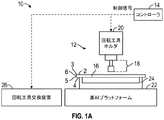
図1Aは、コンピュータ制御機械加工システム12及び機械加工システムコントローラ14を含むアセンブリ10を示す。コントローラ14は、機械加工システム12に回転工具18を用いて基材16を機械加工、研削、又は研磨させるために制御信号を機械加工システム12に送るように構成されており、回転工具18は機械加工システム12の回転工具ホルダ20内に取り付けられている。一実施形態では、機械加工システム12は、経路指定、旋削、ドリル加工、ミリング加工、研削、研磨、及び/又は他の機械加工作業を実行することが可能な、3軸、4軸、又は5軸CNCマシンなどのCNCマシンを表し得、コントローラ14は、1つ以上の回転工具18を用いて基材16の機械加工、研削、及び/又は研磨を実行するために回転工具ホルダ20に命令を出すCNCコントローラを含み得る。コントローラ14は、ソフトウェアを実行する汎用コンピュータを含んでもよく、そのようなコンピュータをCNCコントローラと組み合わせて、コントローラ14の機能を提供してもよい。
FIG. 1A shows an
基材16は、機械加工システム12による基材16の精密な機械加工を容易にするように、基材プラットフォーム22に取り付けられ、固定される。基材保持固定具24は、基材16を基材プラットフォーム22に固定し、基材16を機械加工システム12に対して正確に位置決めする。基材保持固定具24はまた、機械加工システム12の制御プログラムのための基準位置を提供することができる。本明細書に開示される技術は、任意の材料からなるワークピースに適用することができるが、基材16は電子機器用構成要素であってもよい。いくつかの実施形態では、基材16は、電子機器用カバーガラス、より具体的には、スマートフォンタッチスクリーンのカバーガラスなど、電子機器用ディスプレイ素子、例えば、透明ディスプレイ素子であってもよい。例えば、このようなカバーガラスは、高度の平面性及び傾斜度が所望される面取りされたエッジを含み得る。
The
いくつかの実施形態では、基材16は、第1の主面2(例えば、基材16の上部)、第2の主面4(例えば、基材16の底部)、及び1つ以上のエッジ表面6(例えば、基材16の側部)を含み得る。基材16のエッジ表面6の面積は、典型的には、基材16の第1の主面及び/又は第2の主面の面積よりも小さい。いくつかの実施形態では、基材16のエッジ表面6の基材16の第1の主面2の面積に対する比、及び/又は基材16のエッジ表面6の基材16の第2の主面4の面積に対する比は、0.00001を超える、0.0001を超える、0.0005を超える、0.001を超える、0.005を超える、又は更には0.01を超える;0.1未満、0.05未満、又は更に0.02未満とすることができる。いくつかの実施形態では、第1の主面2及び/又は第2の主面4に対して垂直に測定されるエッジ表面6の厚さは、5mm以下、4mm以下、3mm以下、2mm以下、又は更には1mm以下である。エッジ表面6は、第1の主面2と交差して第1の角部3を形成し、第2の主面4と交差して第2の角部5を形成する。いくつかの実施形態では、エッジ表面6は、主面2、4のそれぞれに対して実質的に垂直であってもよく、一方、他の実施例では、エッジ表面6は、2つ以上のエッジ表面を含んでもよく、それらの2つ以上のエッジ表面のうちの少なくとも1つは垂直ではない(例えば、面取りされたエッジ)。基材16の研磨中、研磨中に材料が除去されるときに第1の角部3及び第2の角部5が鋭く輪郭がはっきりしたままであり得るように、1つ以上のエッジ表面6を研磨してもよい。基材16の更なる実施形態を以下の図1D〜図1E及び図2A〜図2Cに説明する。
In some embodiments, the
図1Aの実施形態では、回転工具18を利用して、カバーガラス内の穴及びエッジ特徴部などの基材16の機械加工された特徴部の表面仕上げを改善することができる。いくつかの実施形態では、別々の回転工具18を連続して使用して、機械加工された特徴部の表面仕上げを反復的に改善することができる。例えば、アセンブリ10を利用して、第1の回転工具18又は1組の回転工具18を使用してより粗い研削工程を提供し、続いて、第2の回転工具18又は1組の回転工具18を使用してより細かい研磨工程を提供することができる。いくつかの実施形態では、より少数の回転工具18を使用して反復研削及び/又は研磨プロセスを容易にするために、1つの回転工具18が、様々に異なる研磨レベルを含むことができる。これらの実施形態のそれぞれは、基材内の特徴部の機械加工後の表面仕上げを改善するために1つの研削工程のみを使用する他の実施形態と比較して、基材の特徴部の機械加工後の基材の仕上げ及びポリッシングのサイクル時間を短縮することができる。いくつかの実施形態では、基材は、別々の回転工具18の反復の間ずっと基材保持固定具24に固定されたままであり得る。
In the embodiment of FIG. 1A, the
図1Aの実施形態では、アセンブリ10は、回転工具交換装置26を含む。回転工具交換装置26及び/又は機械加工システム12は、回転工具18の使用済み研磨アセンブリを取り外し、回転工具18の新しい研磨アセンブリを取り付けるように構成してもよい。例えば、研磨アセンブリホルダなどの回転工具18の一部分は、回転工具ホルダ20に固定されたままであってもよく、一方、基材16の表面を研磨するように構成された研磨アセンブリなどの回転工具18の他の部分を交換することができる。回転工具交換装置26の更なる動作を以下の図5A〜図5B及び図6において説明することができる。
In the embodiment of FIG. 1A, the
いくつかの実施形態では、アセンブリ10を使用した研削及び/又は研磨に続いて、基材は、例えば、表面仕上げを更に改善するために別個のポリッシングシステムを使用してポリッシングしてもよい。一般に、ポリッシング前の表面仕上げが良好であるほど、ポリッシング後に所望の表面仕上げをもたらすために必要な時間が短くなる。アセンブリ10を用いて基板16のエッジを研磨するために、コントローラ14は、回転工具ホルダ20が回転工具18を回転させるときに、基材16の1つ以上の特徴部に対して回転工具18の研磨層を精密に適用するように回転工具ホルダ20に命令を出すことができる。命令は、例えば、1つの研磨用回転工具18を用いて基材16の特徴部の輪郭を精密にたどる命令を含んでもよい。装置26は、回転工具18の研磨アセンブリ/研磨層を自動的に補充するために、又は回転工具18の形状を部分的若しくは完全に変化させるために、回転工具18のための研磨層を有する交換用研磨アセンブリを収容している。
In some embodiments, following grinding and / or polishing with the
本明細書で説明される実施形態によれば、研磨用回転工具18は、一定期間にわたって基材16の表面に対して均一な接触圧を加えるように構成される。研磨用回転工具18は、研磨アセンブリホルダと、研磨アセンブリホルダに結合された研磨アセンブリとを含む。研磨アセンブリホルダは、回転工具18の回転軸を画定するシャンクを含む。研磨アセンブリは、剛性支持層と、基材16から材料を除去するように構成された接触面を有する研磨層とを含む。剛性支持層は、研磨層を支持し、接触面における接触力の伝達中に研磨層の接触面を実質的に平坦な向きに維持するように構成される。回転工具18は、研磨機から加えられた1つ以上の力を受ける研磨アセンブリホルダのシャンクと、接触面を通して基材に接触圧を加える研磨アセンブリの研磨層と、の間に配置された弾性層を更に含む。弾性層は、接触面における接触力の伝達中に圧縮するように構成される。このようにして、回転工具18は、平面性を維持しながら、改善された接触を示す接触面を呈することができる。
According to the embodiments described herein, the polishing
図1B及び図1Cは、図1Aの回転工具18として使用することができるような例示的な回転工具を示す。図1Bは、回転工具30の回転軸46に対して実質的に垂直な力を加えるための円筒形研磨用回転工具30を示し、図1Cは、回転工具50の回転軸66に対して実質的に平行な力を加えるための円錐形研磨用回転工具50を示す。円筒形及び円錐形の研磨用回転工具が図1B及び図1Cに示されているが、他の形態の研磨用回転工具を使用してもよい。例えば、平坦な接触面から力を加えるためには、図3A〜図3C、図4A〜図4B、及び図5A〜図5Bに示されるように、回転軸に垂直な接触面を有する円筒形研磨用回転工具を使用することができる。
1B and 1C show exemplary rotary tools that can be used as the
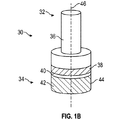
図1Bの実施形態を参照すると、回転工具30は、研磨アセンブリホルダ32及び研磨アセンブリ34を含む。研磨アセンブリホルダ32は、回転工具30の回転軸46を画定するシャンク36を含む。研磨アセンブリ34は、例えば、永久的又は非永久的結合機構(図示せず)を通して、研磨アセンブリホルダ32に結合される。研磨アセンブリ34は、剛性支持層40及び研磨層42を含む。研磨層42は、回転軸46に対して実質的に平行(例えば、5度以内)である接触面44を含む。図1Bの実施形態では、回転工具30は、シャンク36と研磨層42との間に配置された弾性層38を含む。弾性層38は、研磨アセンブリホルダ32又は研磨アセンブリ34の一部であってもよい。
Referring to the embodiment of FIG. 1B, the
図1Cの実施形態を参照すると、回転工具50は、研磨アセンブリホルダ52及び研磨アセンブリ54を含む。研磨アセンブリホルダ52は、回転工具50の回転軸66を画定するシャンク56を含む。研磨アセンブリ54は、例えば、永久的又は非永久的結合機構(図示せず)を通して、研磨アセンブリホルダ52に結合される。研磨アセンブリ54は、剛性支持層60及び研磨層62を含む。研磨層62は、回転軸66と夾角を形成する接触面64を含む。いくつかの実施形態では、接触面64と回転軸62との間の夾角は、図1Cに示すように、5度〜90度、5度〜85度、5度〜80度、又は更には5度〜70度とすることができる。図1Cの実施形態では、回転工具50は、シャンク56と研磨層52との間に配置された弾性層58を含む。弾性層58は、研磨アセンブリホルダ52又は研磨アセンブリ54の一部であってもよい。
Referring to the embodiment of FIG. 1C, the
図1Dは、矢印78によって示されるように、x軸に沿って基材70を研磨する円筒形研磨用回転工具30の側面断面図を示す。基材70は、隣接する表面と交差して第1の角部74及び第2の角部76を形成するエッジ表面72を含む。基材70は、例えば、カバーガラスの外側エッジであり得る。回転工具30は回転軸46の周りを回転し、接触面44をエッジ表面72において基材70に接触させる。図1の回転工具ホルダ20などの回転工具ホルダ(図示せず)は、回転工具30が基材70のエッジ表面72に接触圧を加えるように、矢印78によって示されるように、シャフト36に対して回転軸46に垂直な力を加えることができる。接触面44がエッジ表面72に接触すると、弾性層38は、加えられた力に実質的に平行な(例えば、10度以内の)方向(x軸)での接触面44の移動を可能にする一方で、接触面44は、エッジ表面72に対して実質的に平坦な向きを維持するか、又は角度が所望される場合には、弾性層38の一方の側で圧縮して他方の側で拡張するかのいずれかであり得る。結果として、接触面44は、角部74及び76がそれらの傾斜度を維持するように、エッジ表面72から材料を均等に除去することができる。
FIG. 1D shows a side sectional view of a cylindrical
図1Eは、z軸に沿って基材80を研磨する円錐形研磨用回転工具50の側面断面図を示す。研磨用回転工具50は、回転工具50の回転軸66を画定するシャンク56を含む研磨アセンブリホルダ52と、剛性支持層60及び研磨層62を含む研磨アセンブリ54とを含む。基材80は、隣接する表面と交差して第1の角部84及び第2の角部86を形成する面取りされた面82を含む。基材80は、例えば、穴など、カバーガラスの内側エッジであってもよい。回転工具50は回転軸66の周りを回転し、接触面64を面取りされた面82において基材80に接触させる。図1Aの回転工具ホルダ20などの回転工具ホルダ(図示せず)は、回転工具50が基材80の面取りされた面82に接触圧を加えるように、矢印88によって示されるように、シャフト56に対して下向きの力を加えることができる。接触面64が面取りされた面82と接触すると、弾性層58は、圧縮されて、加えられた力に実質的に平行な方向(z軸)での接触面64の移動を可能にする一方で、接触面64は、面取りされた面82に対して実質的に平坦な向きを維持する。その結果、接触面64は、面取りされた面82から材料を均等に除去することができる。
FIG. 1E shows a side sectional view of a conical
研磨アセンブリホルダ32及び52などの本明細書で説明される研磨アセンブリホルダは、研磨アセンブリ34及び54などの研磨アセンブリに結合するように構成することができる。いくつかの実施例では、研磨アセンブリホルダは、非永久的結合層(例えば、図3〜図6で更に説明されるように、磁気結合層)を介して、研磨アセンブリに直接結合する(すなわち、同じ境界面を共有する)ことができる。いくつかの実施形態では、研磨アセンブリホルダは、結合層(例えば、熱硬化性の高強度接着剤)、弾性層、又は他の層を介して、研磨アセンブリに間接的に結合することができる。研磨アセンブリホルダはまた、図1Aの回転工具ホルダ20などの回転工具ホルダに結合するように構成してもよい。例えば、研磨アセンブリホルダのシャンクは、回転工具ホルダに取り付けるように構成された形状、表面、又は他の特徴部を有してもよい。
The polishing assembly holders described herein, such as the polishing
本明細書で説明される研磨アセンブリホルダは、シャンクの回転軸の周りの回転力、及びx軸、y軸、又はz軸のうちの少なくとも1つに沿った方向性のある力など、回転工具ホルダから加えられた力を受けて、加えられた力の少なくとも一部を研磨アセンブリに伝達するように構成してもよい。図1Dの実施形態では、研磨アセンブリホルダ32のシャンク36は、回転軸46の周りの回転力及びx軸に沿った力を受け、回転力及びx軸力を研磨アセンブリ34に伝達する。図1Eの実施形態では、研磨アセンブリホルダ32のシャンク56は、回転軸66の周りの回転力及びz軸に沿った力を受け、回転力及びz軸力を研磨アセンブリ54に伝達する。
The polishing assembly holder described herein is a rotating tool, such as a rotational force around the axis of rotation of the shank and a directional force along at least one of the x-axis, y-axis, or z-axis. It may be configured to receive the force applied from the holder and transfer at least a portion of the applied force to the polishing assembly. In the embodiment of FIG. 1D, the
研磨アセンブリ34及び54などの本明細書で説明される研磨アセンブリは、研磨アセンブリホルダ32及び52などの研磨アセンブリホルダに結合するように構成することができる。いくつかの実施形態では、研磨アセンブリは、非永久的結合層を介してなど、研磨アセンブリホルダに直接結合することができるが、他の実施形態では、研磨アセンブリは、研磨アセンブリホルダに間接的に結合することができる。
The polishing assemblies described herein, such as the
本明細書で説明される研磨アセンブリホルダは、シャンクの回転軸の周りの回転力、及びx軸、y軸、又はz軸のうちの少なくとも1つに沿った方向性のある力など、研磨アセンブリホルダから加えられた力を受けて、加えられた力の少なくとも一部を研磨アセンブリの接触面に伝達するように構成してもよい。図1Dの実施形態では、研磨アセンブリ34は、弾性層38を介して回転軸46の周りの回転力及びx軸に沿った力を受け、回転力及びx軸力を接触面44に伝達する。図1Eの実施形態では、研磨アセンブリ54は、弾性層58を介して回転軸66の周りの回転力及びz軸に沿った力を受け、回転力及びz軸力を接触面64に伝達する。
The polishing assembly holder described herein is a polishing assembly that includes a rotational force around the axis of rotation of the shank and a directional force along at least one of the x-axis, y-axis, or z-axis. It may be configured to receive the force applied from the holder and transfer at least a portion of the applied force to the contact surface of the polishing assembly. In the embodiment of FIG. 1D, the polishing
剛性支持層40及び60などの本明細書で説明される剛性支持層は、研磨アセンブリの基材に対する接触圧に応答して、研磨層42及び62などの研磨層を支持するように構成することができる。剛性支持層は、基板の研磨中に通常遭遇する圧力などの研磨層からの接触圧を受け、変形に抵抗して剛性支持層と研磨層との間の境界面における平面性を実質的に維持することによって、研磨層を支持することができる。対照的に、弾性層38及び58など、本明細書で説明される弾性層は、基材に対する研磨アセンブリの接触圧に応答して変形するように構成することができる。弾性層は、剛性支持層、結合層、又は弾性層との境界面を形成する他の層などからの接触圧を受け、弾性層の少なくとも一部分において圧縮することによって変形し得る。
The rigid support layers described herein, such as the rigid support layers 40 and 60, are configured to support the polishing layers such as the polishing layers 42 and 62 in response to the contact pressure of the polishing assembly against the substrate. Can be done. The rigid support layer receives contact pressure from the abrasive layer, such as the pressure normally encountered during polishing of the substrate, resists deformation and substantially maintains flatness at the interface between the rigid support layer and the abrasive layer. By doing so, the polishing layer can be supported. In contrast, the elastic layers described herein, such as the
いくつかの実施形態では、剛性支持層及び弾性層はそれぞれ、柔らかさに応じて選択された材料から構成してもよい。材料の柔らかさは、材料のなじみ性と相関し得るものであり、一般に、より軟質の材料ほど、所与の接触圧においてより高いなじみ性を有する。柔らかさは、剛性支持層及び弾性層の各材料の様々な特性によって表され、またそれらに基づいて選択してもよい。例えば、より軟質の材料は、より低い硬度を有する材料(ショアA若しくはショアOOなどの任意の適切な硬度スケールを使用して示される)、より低い弾性率を有する材料、より高い圧縮率を有する材料(典型的には、材料のポアソン比若しくはたわみによって定量化される)、又は発泡体などの複数の気体含有物を含有するなど改質構造を有する材料であり得る。 In some embodiments, the rigid support layer and the elastic layer may each be composed of materials selected according to their softness. The softness of the material can correlate with the familiarity of the material, and in general, the softer the material, the higher the familiarity at a given contact pressure. Softness is represented by the various properties of each material of the rigid support layer and the elastic layer, and may be selected based on them. For example, softer materials have lower hardness materials (shown using any suitable hardness scale such as Shore A or Shore OO), materials with lower modulus, and higher compressibility. It can be a material (typically quantified by the Poisson's ratio or deflection of the material) or a material having a modified structure, such as containing a plurality of gas-containing substances such as foams.
いくつかの実施形態では、剛性支持層及び弾性層はそれぞれ、硬度に応じて選択された材料から構成してもよい。硬度は、力に反応した剛性支持層及び弾性層のそれぞれの測定値を表してもよい。場合によっては、剛性支持層及び弾性層に別々のスケール(例えば、弾性層にショアAデュロメータ及び剛性支持層にロックウェルスケール)を使用して、硬度を最も適切に測定することができる。いくつかの実施形態では、剛性支持層は、剛性支持層が通常の動作条件下で基材に対して実質的に変形しないように、十分に高い硬度を有する。いくつかの実施形態では、剛性支持層は、約90ショアAを超える、又は約95ショアAを超える硬度を有することがある。いくつかの実施形態では、弾性層は、弾性層が通常の動作条件下で基材に対して変形するように、十分に低い硬度を有する。いくつかの実施形態では、弾性層は、約70ショアA未満、又は約50ショアA未満、又は約40ショアA未満、又は約30ショアA未満、又は約20ショアA未満、又は約10ショアA未満の硬度を有することがある。 In some embodiments, the rigid support layer and the elastic layer may each be composed of a material selected according to hardness. The hardness may represent the measured values of the rigid support layer and the elastic layer in response to the force. In some cases, separate scales for the rigid and elastic layers (eg, Shore A durometer for the elastic layer and Rockwell scale for the elastic layer) can be used to best measure hardness. In some embodiments, the rigid support layer has a sufficiently high hardness so that the rigid support layer does not substantially deform with respect to the substrate under normal operating conditions. In some embodiments, the rigid support layer may have a hardness greater than about 90 shore A, or greater than about 95 shore A. In some embodiments, the elastic layer has a sufficiently low hardness so that the elastic layer deforms with respect to the substrate under normal operating conditions. In some embodiments, the elastic layer is less than about 70 shore A, or less than about 50 shore A, or less than about 40 shore A, or less than about 30 shore A, or less than about 20 shore A, or about 10 shore A. May have less than hardness.
いくつかの実施形態では、剛性支持層及び弾性層はそれぞれ、圧縮率に応じて選択された材料から構成してもよい。圧縮率は、圧力に反応した剛性支持層及び弾性層のそれぞれの材料の相対的変化の測定値を表すことがあるが、「圧縮可能な」又は「圧縮不可能な」という用語は、圧縮性の材料特性を指すこともある。例えば、用語「実質的に圧縮不可能」は、約0.45を超えるポアソン比を有する材料を指す。材料の圧縮率は、材料を基準たわみ(例えば、25%たわみ)に圧縮するために必要な特定の圧力として表現することができる。いくつかの実施形態では、層の圧縮率は、層が発泡体であるとき、ASTM D3574又はその修正版による圧縮力たわみ試験により、及び、層が例えばスポンジ又は拡張可能なゴムなどの柔軟な海綿状材料であるとき、ASTM D1056による圧縮たわみ試験により測定することができる。 In some embodiments, the rigid support layer and the elastic layer may each be composed of materials selected according to the compressibility. Compressibility may represent a measure of the relative changes in the materials of a rigid support layer and an elastic layer in response to pressure, while the terms "compressible" or "non-compressible" are compressible. It may also refer to the material properties of. For example, the term "substantially incompressible" refers to a material having a Poisson's ratio greater than about 0.45. The compressibility of a material can be expressed as the specific pressure required to compress the material to a reference deflection (eg, 25% deflection). In some embodiments, the compressibility of the layer is determined by a compressive deflection test with ASTM D3574 or a modified version thereof when the layer is foam, and the layer is a flexible sponge such as a sponge or expandable rubber. When it is a state material, it can be measured by a compression deflection test with ASTM D1056.
いくつかの実施形態では、弾性層の圧縮率は、研磨中に遭遇する動作条件について比較的高くなる場合がある。いくつかの実施形態では、弾性層は、25%たわみでの約1.5MPa(220psi)未満、約1.1MPa(160psi)未満、約0.31MPa(45psi)未満の圧縮率、及び/又は約0.5未満、約0.4未満、0.3未満、又は好ましくは約0.1.未満のポアソン比を有し得る。 In some embodiments, the compressibility of the elastic layer may be relatively high with respect to the operating conditions encountered during polishing. In some embodiments, the elastic layer has a compressibility of less than about 1.5 MPa (220 psi), less than about 1.1 MPa (160 psi), less than about 0.31 MPa (45 psi) at 25% deflection, and / or about. Less than 0.5, less than about 0.4, less than 0.3, or preferably about 0.1. It can have a Poisson's ratio of less than.
いくつかの実施形態では、剛性支持層は、実質的に圧縮不可能であってもよく、例えば、接触圧に反応した材料の相対的体積変化は、5%未満、2%未満、1%未満、0.5%未満、又は0.2%未満である。 In some embodiments, the rigid support layer may be substantially incompressible, eg, the relative volume change of the material in response to contact pressure is less than 5%, less than 2%, less than 1%. , Less than 0.5%, or less than 0.2%.
いくつかの実施形態では、剛性支持層及び弾性層はそれぞれ、弾性率に応じて選択された材料から構成してもよい。弾性率(又は剛性率)は、圧力(応力)に反応した剛性支持層及び弾性層のそれぞれの材料の相対的変形(ひずみ)の測定値を表すことがあるが、「弾性の」又は「非弾性の」という用語は、弾性の材料特性を指すこともある。例えば、「実質的に非弾性」という用語は、約0.45を超えるポアソン比を有する材料を指す。材料の弾性率は、引張弾性率、ヤング率、又は弾性率として表すことができる。いくつかの実施形態では、層の弾性率は、ASTM E111−17によるヤング率、接線係数、及びコード弾性率の標準試験方法により測定することができる。 In some embodiments, the rigid support layer and the elastic layer may each be composed of a material selected according to the elastic modulus. The modulus of elasticity (or modulus of rigidity) may represent a measure of the relative deformation (strain) of the materials of the rigid support layer and the elastic layer in response to pressure (stress), but may be "elastic" or "non-elastic". The term "elastic" may also refer to elastic material properties. For example, the term "substantially inelastic" refers to a material having a Poisson's ratio greater than about 0.45. The elastic modulus of a material can be expressed as tensile elastic modulus, Young's modulus, or elastic modulus. In some embodiments, the modulus of elasticity of the layer can be measured by standard test methods for Young's modulus, tangential modulus, and cord modulus according to ASTM E111-17.
いくつかの実施形態では、剛性支持層は、剛性支持層が通常の動作条件下で基材に対して実質的に変形しないように、十分に低い弾性を有する。いくつかの実施形態では、剛性弾性層は、実質的に非弾性であってもよく、例えば、接触圧に反応した材料の相対的体積変化は、5%未満、2%未満、1%未満、0.5%未満、又は0.2%未満である。いくつかの実施形態では、剛性支持層は、所望のなじみ性をもたらすようにパターン化された、3D印刷された、エンボス加工された、又は彫られた実質的に圧縮不可能な材料で作製される。いくつかの実施形態では、剛性支持層は、アルミニウム6061、2011、若しくは2024、又は鋼4140、W1、若しくは01などの金属;ナイロン、ポリカーボネート、若しくはアクリルなどのプラスチック;ゴムなどのうちの少なくとも1つを含む。 In some embodiments, the rigid support layer has sufficiently low elasticity so that the rigid support layer does not substantially deform with respect to the substrate under normal operating conditions. In some embodiments, the rigid elastic layer may be substantially inelastic, for example, the relative volume change of the material in response to contact pressure is less than 5%, less than 2%, less than 1%. Less than 0.5% or less than 0.2%. In some embodiments, the rigid support layer is made of a 3D printed, embossed, or carved, virtually incompressible material that is patterned to provide the desired familiarity. NS. In some embodiments, the rigid support layer is at least one of aluminum 6061, 2011, or 2024, or a metal such as steel 4140, W1, or 01; a plastic such as nylon, polycarbonate, or acrylic; rubber or the like. including.
いくつかの実施形態では、弾性層は、弾性層が通常の動作条件下で基材に対して圧縮するように、十分に高い弾性を有する。いくつかの実施形態では、弾性層は、約1.5MPa(220psi)未満、約1.1MPa(160psi)未満、約0.31MPa(45psi)未満のヤング率、及び/又は約0.5未満、約0.4未満、0.3未満、又は好ましくは約0.1.未満のポアソン比を有し得る。いくつかの実施形態では、弾性層は、エラストマー、布地、不織布材料、又はばねのうちの少なくとも1つを含む。 In some embodiments, the elastic layer has sufficiently high elasticity that the elastic layer compresses against the substrate under normal operating conditions. In some embodiments, the elastic layer has a Young's modulus of less than about 1.5 MPa (220 psi), less than about 1.1 MPa (160 psi), less than about 0.31 MPa (45 psi), and / or less than about 0.5. Less than about 0.4, less than 0.3, or preferably about 0.1. It can have a Poisson's ratio of less than. In some embodiments, the elastic layer comprises at least one of an elastomer, a fabric, a non-woven material, or a spring.
いくつかの実施形態では、弾性層は、弾性変形に応じて選択された材料から構成してもよい。弾性変形は、変形後に材料がその元の状態に回復する能力を表し得る。材料は、弾性的に変形可能とすることができ、例えば、変形された後に元の状態に回復することが、実質的に100%(例えば、90%以上、95%以上、99%以上、99.5%以上、又は99.9%以上)可能である。 In some embodiments, the elastic layer may be composed of a material selected according to the elastic deformation. Elastic deformation can represent the ability of a material to recover to its original state after deformation. The material can be elastically deformable, eg, being deformed and then restored to its original state is substantially 100% (eg, 90% or more, 95% or more, 99% or more, 99). 5.5% or more, or 99.9% or more) is possible.
いくつかの実施形態では、弾性層は、緩和弾性率、例えば応力緩和弾性率に応じて選択された材料から構成してもよい。緩和弾性率は、時間依存性粘弾特性の測定値を表すことがある。本開示では、緩和弾性率は百分率で表され、以下の等式を使用して(例えば、ASTM D6048を使用して測定されるような)応力緩和試験からもたらされる緩和弾性率対時間曲線から決定される。 In some embodiments, the elastic layer may be composed of a material selected according to the relaxation modulus, eg, the stress relaxation modulus. The relaxed modulus may represent a measure of time-dependent viscous properties. In the present disclosure, the relaxation modulus is expressed as a percentage and is determined from the relaxation modulus vs. time curve resulting from a stress relaxation test using the following equation (eg, as measured using ASTM D6048). Will be done.
緩和弾性率(%)=(瞬間弾性率−一定の圧縮ひずみ下で2分の緩和後の弾性率)/瞬間弾性率×100いくつかの実施形態において、剛性支持層及び弾性層のうちの少なくとも1つが、25%未満の緩和弾性率を有する。 Relaxation modulus (%) = (Instantaneous modulus-Elastic modulus after relaxation for 2 minutes under constant compressive strain) / Momentary modulus x 100 In some embodiments, at least of the rigid support layer and the elastic layer. One has a relaxed modulus of less than 25%.
いくつかの実施形態では、弾性層は、様々な厚さに構成してもよい。例えば、弾性層の厚さは、弾性層の反発力又は反発距離と相関し得るため、弾性層は、弾性層によって生成される力又は吸収される力に関して特定の範囲又は移動距離を提供する厚さを有することができる。一例として、比較的高度な平面性を有する基材を対象とする研磨用回転工具の弾性層は、比較的低度な平面性を有する基材を対象とする研磨用回転工具の弾性層よりも薄くてもよく、これは、平面性がより高いと、弾性層の圧縮又は移動が少なくなり得るためである。いくつかの実施形態では、弾性層の厚さは、3mm未満、2mm未満、又は1mm未満であってもよい。いくつかの実施形態では、弾性層は、エラストマー、布地、又は不織布材料のうちの少なくとも1つを含む。好適なエラストマーとしては、熱硬化性エラストマー、例えば、ニトリル、フルオロエラストマー、クロロプレン、エピクロロヒドリン、シリコーン、ウレタン、ポリアクリレート、EPDM(エチレンプロピレンジエンモノマー)ゴム、SBR(スチレンブタジエンゴム)、ブチルゴム、ナイロン、ポリスチレン、ポリエチレン、ポリプロピレン、ポリエステル、ポリウレタンなどを挙げることができる。いくつかの実施形態では、弾性層の密度は、0.2g/cm3を超える、0.4g/cm3を超える、0.6g/cm3を超える、0.8g/cm3を超える、0.85g/cm3を超える、0.9g/cm3を超える、0.95g/cm3を超える、1.0g/cm3を超える、1.1g/cm3を超える、又は更には1.2g/cm3を超えてもよく、2.0g/cm3未満、1.8g/cm3未満、1.6g/cm3未満、1.4g/cm3未満、又は更には1.2g/cm3未満であってもよい。 In some embodiments, the elastic layer may be configured with varying thicknesses. For example, the thickness of the elastic layer can correlate with the repulsive force or repulsive distance of the elastic layer, so that the elastic layer provides a specific range or moving distance with respect to the force generated or absorbed by the elastic layer. Can have elasticity. As an example, the elastic layer of a rotating tool for polishing for a base material having a relatively high flatness is larger than the elastic layer of a rotating tool for polishing targeting a base material having a relatively low flatness. It may be thinner, because the higher the flatness, the less compression or movement of the elastic layer can be. In some embodiments, the thickness of the elastic layer may be less than 3 mm, less than 2 mm, or less than 1 mm. In some embodiments, the elastic layer comprises at least one of an elastomeric, fabric, or non-woven material. Suitable elastomers include thermocurable elastomers such as nitrile, fluoroelastomer, chloroprene, epichlorohydrin, silicone, urethane, polyacrylate, EPDM (ethylene propylene diene monomer) rubber, SBR (styrene butadiene rubber), butyl rubber, etc. Nylon, polystyrene, polyethylene, polypropylene, polyester, polyurethane and the like can be mentioned. In some embodiments, the density of the elastic layer is greater than 0.2 g / cm 3 , greater than 0.4 g / cm 3 , greater than 0.6 g / cm 3 , greater than 0.8 g / cm 3 , 0. greater than .85g / cm 3, more than 0.9 g / cm 3, more than 0.95 g / cm 3, more than 1.0 g / cm 3, more than 1.1 g / cm 3, or even 1.2g / cm 3 may be greater than, less than 2.0 g / cm 3, less than 1.8 g / cm 3, less than 1.6 g / cm 3, less than 1.4 g / cm 3, or even 1.2 g / cm 3 It may be less than.
弾性層はまた、上述の1つ以上の特性を有する様々な材料から形成してもよい。いくつかの実施形態では、弾性層が、発泡体、彫られた、構造化された、3D印刷された、又はエンボス加工されたエラストマー、布地若しくは不織布層、又は軟質ゴムのうちの1つ以上を含み得る。好適な発泡体としては、例えば、合成発泡体又は天然発泡体、熱成形発泡体、ポリウレタン、ポリエステル、ポリエーテル、充填又はグラフト化ポリエーテル、粘弾性発泡体、メラミン発泡体、ポリエチレン、架橋ポリエチレン、ポリプロピレン、シリコーン、アイオノマー発泡体などを含む、連続気泡体又は独立気泡体であり得る。弾性層としてはまた、例えば、イソプレン、ネオプレン、ポリブタジエン、ポリイソプレン、ポリクロロプレン、天然ゴム、ニトリルゴム、ポリ塩化ビニル及びニトリルゴム、EPDM(エチレンプロピレンジエンモノマー)などのエチレン−プロピレンコポリマー、並びにブチルゴム(例えば、イソブチレン−イソプレンコポリマー)含む、発泡エラストマー、加硫ゴムを挙げることができる。いくつかの実施形態では、弾性層は、様々な圧縮性構造体を含む。例えば、弾性層は、ばね、不織布、布地、エアブラダーなどの任意の好適な圧縮性構造体を含んでもよい。いくつかの実施形態では、弾性層は、所望のポアソン比、圧縮率、及び弾性応答をもたらすように、3D印刷してもよい。いくつかの実施形態では、弾性層の密度は、0.2g/cm3を超える、0.25g/cm3を超える、0.3g/cm3を超える、0.35g/cm3を超える、0.4g/cm3を超える、0.45g/cm3を超える、又は更には0.50g/cm3を超えてもよい;1.2g/cm3未満、1.0g/cm3未満、0.95g/cm3未満、0.90g/cm3未満、0.85g/cm3未満、0.80g/cm3未満、0.75g/cm3未満、又は更には0.70g/cm3未満であってもよい。 The elastic layer may also be formed from a variety of materials having one or more of the properties described above. In some embodiments, the elastic layer is one or more of a foam, carved, structured, 3D printed or embossed elastomer, fabric or non-woven layer, or soft rubber. Can include. Suitable foams include, for example, synthetic or natural foams, thermoformed foams, polyurethanes, polyesters, polyethers, filled or grafted polyethers, viscoelastic foams, melamine foams, polyethylene, crosslinked polyethylenes, etc. It can be an open cell or closed cell, including polypropylene, silicone, ionomer foam, and the like. The elastic layer also includes, for example, isoprene, neoprene, polybutadiene, polyisoprene, polychloroprene, natural rubber, nitrile rubber, polyvinyl chloride and nitrile rubber, ethylene-propylene copolymers such as EPDM (ethylene propylene diene monomer), and butyl rubber ( For example, foamed elastomers and vulture rubbers containing (isoprene-isoprene copolymer) can be mentioned. In some embodiments, the elastic layer comprises various compressible structures. For example, the elastic layer may include any suitable compressible structure such as springs, non-woven fabrics, fabrics, air bladder and the like. In some embodiments, the elastic layer may be 3D printed to provide the desired Poisson's ratio, compressibility, and elastic response. In some embodiments, the density of the elastic layer is greater than 0.2 g / cm 3 , greater than 0.25 g / cm 3 , greater than 0.3 g / cm 3 , greater than 0.35 g / cm 3 , 0. it exceeds .4g / cm 3, more than 0.45 g / cm 3, or even 0.50 g / cm 3 and even may exceed; 3 less than 1.2 g / cm, less than 1.0g / cm 3, 0. Less than 95 g / cm 3, less than 0.90 g / cm 3, less than 0.85 g / cm 3, less than 0.80 g / cm 3, less than 0.75 g / cm 3 , or even less than 0.70 g / cm 3. You may.
研磨層42及び62などの本明細書で説明される研磨層は、接触面44及び64などの接触面を含む。接触面は、基材の1つ以上の表面に接触し、研磨するように構成される。研磨は、研削、ポリッシング、及び基材から材料を除去する任意の他の作用を含み得る。当業者であれば認識するように、接触面は、例えば、成形、押出、エンボス加工、及びこれらの組み合わせを含めた多様な方法に従って形成することができる。 The polishing layers described herein, such as the polishing layers 42 and 62, include contact surfaces such as the contact surfaces 44 and 64. The contact surface is configured to contact and polish one or more surfaces of the substrate. Polishing may include grinding, polishing, and any other action of removing material from the substrate. As will be appreciated by those skilled in the art, contact surfaces can be formed according to a variety of methods, including, for example, molding, extrusion, embossing, and combinations thereof.
研磨層は、特に限定されず、従来のコーティングされた研磨剤及び構造化研磨剤(例えば、3M Company(St.Paul,Minnesota)から入手可能な3M TRIZACT ABRASIVE)が挙げられ得るが、これらに限定されない。研磨層は、基層(例えば、バッキング層)及び接触層を含み得る。基層は、高分子材料から形成することができる。例えば、基層は、ポリプロピレン、ポリエチレン、ポリエチレンテレフタレートなどの熱可塑性樹脂、ポリウレタン、エポキシ樹脂などの熱硬化性樹脂、又はこれらの任意の組み合わせから形成することができる。基層は、任意の数の層を含んでもよい。基層の厚さ(すなわち、第1及び第2の主面に対して垂直方向の基層の寸法)は、10mm未満、5mm未満、1mm未満、0.5mm未満、0.25mm未満、0.125mm未満又は0.05mm未満であってよい。 The polishing layer is not particularly limited and may include, but is limited to, conventional coated abrasives and structured abrasives (eg, 3M TRIZACT ABRASIVE available from 3M Company (St. Paul, Minnesota)). Not done. The polishing layer may include a base layer (eg, a backing layer) and a contact layer. The base layer can be formed from a polymeric material. For example, the base layer can be formed from a thermoplastic resin such as polypropylene, polyethylene or polyethylene terephthalate, a thermosetting resin such as polyurethane or epoxy resin, or any combination thereof. The base layer may include any number of layers. The thickness of the base layer (ie, the dimensions of the base layer perpendicular to the first and second main surfaces) is less than 10 mm, less than 5 mm, less than 1 mm, less than 0.5 mm, less than 0.25 mm, less than 0.125 mm. Alternatively, it may be less than 0.05 mm.
いくつかの実施形態では、研磨層の接触面は、微細構造化表面(microstructured surface)を含む。微細構造化表面は、基材の1つ以上の表面上への接触面の接触圧を増加させるように構成された微細構造体を含み得る。いくつかの実施形態では、微細構造化表面は、研磨層の最も外側の研磨材の間に間隔を空けて配置された複数のキャビティを含み得る。例えば、キャビティの形状は、立方体、円筒形、プリズム形、半球形、直方体、角錐形、切頭角錐形、円錐形、切頭円錐形、十字形、弓状若しくは平坦な底部表面を持つ柱状、又はこれらの組み合わせ等の多数の幾何学的形状の中から選択することができる。あるいは、キャビティのいくつか又は全てが不規則形状を有してもよい。種々の実施形態では、キャビティを形成する側壁又は内壁の1つ以上が主面上部に対して垂直であってもよいし、あるいは、いずれかの方向に次第に細くなってもよい(すなわち、キャビティの底部又はキャビティの上部に向かって(主面に向かって)テーパが形成される)。テーパを形成する角度は、約1〜75度、約2〜50度、約3〜35度、又は約5〜15度の範囲であってよい。キャビティの高さ、つまり深さは、少なくとも1ミクロン、少なくとも10ミクロン、又は少なくとも500ミクロン、又は少なくとも1000ミクロン;10mm未満、5mm未満、又は1mm未満であり得る。キャビティの高さは同じであってもよく、又はキャビティのうちの1つ以上は、任意の数の他のキャビティと異なる高さを有してもよい。いくつかの実施形態では、キャビティが整列された行及び列になる配列でキャビティを設けることができる。場合によっては、キャビティの1つ以上の行は、キャビティの隣り合う行と直線的に整列され(directly Aligned)得る。あるいは、キャビティの1つ以上の行は、キャビティの隣り合う行からずらしてもよい。更なる実施形態では、キャビティは、螺線状、螺旋状、コルク抜き状又は格子状に配列することができる。更なる実施形態では、複合体を、「ランダムな」配列に(すなわち、組織的パターンでなく)配置してもよい。 In some embodiments, the contact surface of the abrasive layer comprises a microstructured surface. The microstructured surface may include microstructures configured to increase the contact pressure of the contact surface onto one or more surfaces of the substrate. In some embodiments, the microstructured surface may include multiple cavities spaced apart between the outermost abrasives of the abrasive layer. For example, the shape of the cavity is cubic, cylindrical, prismatic, hemispherical, rectangular parallelepiped, pyramidal, truncated pyramidal, conical, truncated cone, crossed, arcuate or columnar with a flat bottom surface. Alternatively, it can be selected from a large number of geometric shapes such as a combination thereof. Alternatively, some or all of the cavities may have an irregular shape. In various embodiments, one or more of the sidewalls or inner walls forming the cavity may be perpendicular to the top of the main surface, or may taper in either direction (ie, the cavity). A taper is formed towards the bottom or the top of the cavity (towards the main surface). The angle at which the taper is formed may range from about 1 to 75 degrees, about 2 to 50 degrees, about 3 to 35 degrees, or about 5 to 15 degrees. The height, or depth, of the cavity can be at least 1 micron, at least 10 microns, or at least 500 microns, or at least 1000 microns; less than 10 mm, less than 5 mm, or less than 1 mm. The heights of the cavities may be the same, or one or more of the cavities may have a height different from any number of other cavities. In some embodiments, the cavities can be arranged in rows and columns in which the cavities are aligned. In some cases, one or more rows of cavities may be directedly aligned with adjacent rows of cavities. Alternatively, one or more rows of cavities may be offset from adjacent rows of cavities. In a further embodiment, the cavities can be arranged in a spiral, spiral, corkscrew or grid pattern. In a further embodiment, the complex may be arranged in a "random" sequence (ie, rather than a tissue pattern).
いくつかの実施形態では、接触面の微細構造化表面は、複数の精密に成形された研磨複合体を含む。「精密形状の研磨複合体」は、研磨複合体が成形型から取り外された後に保持される、金型キャビティの逆である成形形状を有する研磨複合体を指し、好ましくは、この複合体は、その全体が参照により本明細書に組み込まれる米国特許第5,152,917号(Pieperら)に記載されているように、研磨層が使用される前にその形状の露出表面を越えて突出する研磨粒子を実質的に含まない。複数の精密形状の研磨複合体は、固定研磨材を形成する、研磨粒子と樹脂/バインダとの組み合わせを含んでもよい。いくつかの実施形態では、接触面70は、1つ以上の樹脂又は他のバインダ層によってバッキングに保持された研磨粒子からなる層を有する研磨シートなど、二次元研磨材として形成してもよい。あるいは、接触面は、樹脂又は他のバインダ層などの三次元研磨材として形成してもよく、この三次元研磨材は、その中に分散された研磨粒子を含有し、成形又はエンボス加工プロセスにより、(微細構造化表面を形成する)三次元構造体に形成され、例えば、その後、樹脂を硬化、架橋、及び/又は結晶化して、三次元構造体を固化及び維持する。三次元構造体は、複数の精密形状の研磨複合体を含んでいてもよい。いずれの実施形態においても、接触面は研磨複合体を含むことができ、この研磨複合体は、使用中又は仕上げ中に研磨複合体が摩耗することを可能にする適切な高さ及び/又は研磨粒子の新しい層を露出させるのに適した高さを有する。研磨層は、複数の精密形状の研磨複合体を含む、三次元、テクスチャード、軟質の固定研磨構造を含んでいてもよい。精密形状の研磨複合体は、三次元、テクスチャード、軟質の固定研磨構造を形成する配列に配置されていてもよい。研磨層は、パターン化された研磨構造を含んでいてもよい。3M Company(St.Paul,Minnesota)から入手可能なTRIZACTパターン化研磨材及びTRIZACTダイヤモンドタイル研磨材の商品名で入手可能な研磨層は、例示的なパターン化研磨材である。パターン化研磨層は、ダイ、成形型、又は他の手法から精密に配列及び製造される、研磨複合体のモノリシックな列を含む。
In some embodiments, the microstructured surface of the contact surface comprises a plurality of precision molded abrasive complexes. "Precision-shaped polishing composite" refers to a polishing composite having a molding shape that is the reverse of the mold cavity, which is held after the polishing composite is removed from the mold, preferably this composite. As described in US Pat. No. 5,152,917 (Pieper et al.), The entire body of which is incorporated herein by reference, the abrasive layer projects beyond the exposed surface of its shape before it is used. Substantially free of abrasive particles. The plurality of precision-shaped polishing composites may include a combination of polishing particles and a resin / binder that forms a fixed abrasive. In some embodiments, the
精密形状の研磨複合体それぞれの形状は、具体的な用途(例えば、加工物の材質、作業面の形状、接触面の形状、温度、樹脂相の材質)によって選択できる。精密形状の研磨複合体それぞれの形状は、任意の有用な形状、例えば、立方体、円筒形、角柱形、直角平行六面体、角錐形、角錐台、円錐形、半球形、円錐台、十字形、又は遠位端を有する柱様断面であってもよい。複合体角錘は、例えば、3、4面、5面、又は6面を有していてもよい。研磨複合体の底部での断面形状は、遠位端での断面形状と異なっていてもよい。これらの形状間の移行は、滑らかで連続的であってもよいし、不連続な段階を経て生じてもよい。精密形状の研磨複合体はまた、様々な形状の混合であってもよい。精密形状の研磨複合体は、列、渦巻状、螺旋状、又は格子状に構成してもよく、ランダムに配置してもよい。精密形状の研磨複合体は、流体の流れをガイドし、かつ/又は、切屑の除去を容易にするように意図されたデザインで構成できる。 The shape of each precision-shaped polishing complex can be selected according to a specific application (for example, the material of the work piece, the shape of the work surface, the shape of the contact surface, the temperature, and the material of the resin phase). The shape of each precision-shaped polishing composite can be any useful shape, such as a cube, cylinder, prism, right parallel hexahedron, pyramid, pyramid, cone, hemisphere, cone, cross, or It may have a columnar cross section with a distal end. The complex weapon may have, for example, three, four, five, or six faces. The cross-sectional shape at the bottom of the polishing complex may differ from the cross-sectional shape at the distal end. The transition between these shapes may be smooth and continuous or may occur through discontinuous steps. The precision-shaped polishing composite may also be a mixture of various shapes. The precision-shaped polishing composites may be arranged in rows, spirals, spirals, or grids, or may be randomly arranged. The precision-shaped polishing complex can be constructed with a design intended to guide the flow of fluid and / or facilitate the removal of chips.
精密形状の研磨複合体は、所定のパターンで、又は研磨層内の所定の位置に配置できる。例えば、研磨層が、バッキングと成形型との間に研磨/樹脂スラリーを提供することにより作られるとき、精密形状の研磨複合体の所定のパターンは、成形型のパターンに対応すると考えられる。したがって、パターンは、研磨層から研磨層へと再現可能である。所定のパターンは、ある配列又は構成をなしていてもよく、これは、複合体がデザインされた配列、例えば整列した横列及び縦列、又は交互にずれた横列及び縦列をなしていることが意図されている。別の一実施形態において、研磨複合体を、「ランダム」な配列又はパターンに配置できる。この意味するところは、複合体が上述のとおりの横列及び縦列の規則的な配列ではないということである。しかしながら、この「ランダム」な配列は、精密形状の研磨複合体の位置があらかじめ定められ、成形型に対応するという点では、所定のパターンであることが理解される。 The precision-shaped polishing composite can be placed in a predetermined pattern or in a predetermined position within the polishing layer. For example, when the polishing layer is made by providing a polishing / resin slurry between the backing and the molding die, the predetermined pattern of the precision shaped polishing composite is considered to correspond to the pattern of the molding die. Therefore, the pattern can be reproduced from the polishing layer to the polishing layer. The predetermined pattern may be in a certain arrangement or configuration, which is intended to form an array in which the complex is designed, eg, aligned rows and columns, or alternating rows and columns. ing. In another embodiment, the polishing complexes can be arranged in a "random" arrangement or pattern. This means that the complex is not a regular array of rows and columns as described above. However, it is understood that this "random" arrangement is a predetermined pattern in that the position of the precision shaped polishing complex is predetermined and corresponds to the molding die.
研磨層の接触面を形成する研磨材は、樹脂等の高分子材料を含んでもよい。いくつかの実施形態において、樹脂相は、硬化した又は硬化性の有機材料を含んでいてもよい。硬化方法は重要でなく、例えば、エネルギー、例えば紫外線又は熱を介する硬化を含んでいてもよい。好適な樹脂相材料の例としては、例えば、アミノ樹脂、アルキル化尿素ホルムアルデヒド樹脂、メラミン−ホルムアルデヒド樹脂、アルキル化ベンゾグアナミン−ホルムアルデヒド樹脂、アクリレート樹脂(アクリレート及びメタクリレートを含む)、フェノール樹脂、ウレタン樹脂、及びエポキシ樹脂が挙げられる。 The abrasive material forming the contact surface of the abrasive layer may contain a polymer material such as a resin. In some embodiments, the resin phase may comprise a cured or curable organic material. The curing method is not important and may include, for example, curing via energy such as ultraviolet light or heat. Examples of suitable resin phase materials include, for example, amino resins, alkylated urea formaldehyde resins, melamine-formaldehyde resins, alkylated benzoguanamine-formaldehyde resins, acrylate resins (including acrylates and methacrylates), phenol resins, urethane resins, and Epoxy resin can be mentioned.
研磨層に好適な研磨粒子の例には、立方晶窒化ホウ素、溶融酸化アルミニウム、セラミック酸化アルミニウム、熱処理酸化アルミニウム、白色溶融酸化アルミニウム、黒色炭化ケイ素、緑色炭化ケイ素、二ホウ化チタン、炭化ホウ素、窒化ケイ素、炭化タングステン、炭化チタン、ダイヤモンド、立方晶窒化ホウ素、六方晶窒化ホウ素、アルミナジルコニア、酸化鉄、セリア、ガーネット、溶融アルミナジルコニア、アルミナ系ゾルゲル由来研磨粒子などが含まれる。アルミナ研磨粒子は、金属酸化物改質剤を含有していてもよい。ダイヤモンド及び立方晶窒化ホウ素研磨粒子は、単結晶質であっても多結晶質であってもよい。好適な無機研磨粒子の他の例には、シリカ、酸化鉄、クロミア、セリア、ジルコニア、チタニア、酸化スズ、ガンマアルミナ等が含まれる。研磨粒子は、研磨凝集体粒子であってもよい。研磨凝集体粒子は、典型的には、複数の研磨粒子、バインダ、及び任意の添加剤を含む。バインダは、有機であっても無機であってもよい。研磨凝集体は、ランダム形状であってもよく、又はそれらに関連した所定の形状を有してもよい。 Examples of abrasive particles suitable for the abrasive layer include cubic boron nitride, molten aluminum oxide, ceramic aluminum oxide, heat-treated aluminum oxide, white molten aluminum oxide, black silicon carbide, green silicon carbide, titanium diboride, boron carbide, Includes silicon nitride, tungsten carbide, titanium carbide, diamond, cubic boron nitride, hexagonal boron nitride, alumina zirconia, iron oxide, ceria, garnet, molten alumina zirconia, and abrasive particles derived from alumina-based solgel. The alumina abrasive particles may contain a metal oxide modifier. The diamond and cubic boron nitride abrasive particles may be single crystal or polycrystalline. Other examples of suitable inorganic abrasive particles include silica, iron oxide, chromia, ceria, zirconia, titania, tin oxide, gamma alumina and the like. The polishing particles may be polishing aggregate particles. Abrasive agglomerate particles typically include a plurality of abrasive particles, binders, and optional additives. The binder may be organic or inorganic. The abrasive agglomerates may have a random shape or may have a predetermined shape associated with them.
いくつかの実施形態では、樹脂、研磨粒子、及び樹脂中に分散された任意の追加の添加剤を含む研磨層は、剛性支持層上のコーティングであってもよい。いくつかの特定の実施形態では、研磨層は、基層上に堆積された研磨複合体層から形成してもよく、基層は、研磨複合体層と基層との間にプライマー層を含んでもよい。基層自体は、剛性支持層又は弾性層などのバッキング層を覆うように配置してもよく、基層は、接着剤でバッキング層に固定される。 In some embodiments, the abrasive layer containing the resin, abrasive particles, and any additional additives dispersed in the resin may be a coating on a rigid support layer. In some specific embodiments, the polishing layer may be formed from a polishing complex layer deposited on the base layer, and the base layer may include a primer layer between the polishing complex layer and the base layer. The base layer itself may be arranged so as to cover a backing layer such as a rigid support layer or an elastic layer, and the base layer is fixed to the backing layer with an adhesive.
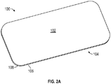
種々の実施形態では、本明細書に記載される研磨用回転工具は、カバーガラスのエッジ又は主面の研削に好適であり得る。例えば、カバーガラスは様々な表面を含み得、それらの表面について、各表面の高度な平面性(すなわち、表面の平坦度)及び表面同士間の高度な傾斜度(すなわち、表面同士間の角度の鋭さ)が所望される。図2Aは、携帯電話、パーソナル音楽プレーヤ、又は他の電子機器などの電子機器用ためのカバーガラスであるカバーガラス100を示す。いくつかの実施形態では、カバーガラス100は、電子機器用タッチスクリーンの構成要素であってもよい。カバーガラス100は、厚さが1mm未満のアルミナシリケートガラスであってもよいが、厚さが5mm未満、4mm未満、3mm未満、又は更には2mm未満などである他の組成物も可能である。
In various embodiments, the rotary tools for polishing described herein may be suitable for grinding the edges or main surfaces of cover glass. For example, the cover glass can include various surfaces, for which the surface has a high degree of flatness (ie, surface flatness) and a high degree of inclination between the surfaces (ie, the angle between the surfaces). Sharpness) is desired. FIG. 2A shows a
カバーガラス100は、第2の主面104に対向する第1の主面102を含む。常にではないが、通常、主面102、104は平坦面である。エッジ表面106は主面102、104の周辺部をたどり、その周辺部は丸みを帯びた角部108を含む。エッジ表面106は、第1の角部で第1の主面102と交差し、第2の角部で第2の主面104と交差し、第1及び第2の角部は、概して、基材の全周の周りに延びている。
The
亀裂に対する耐性の向上と外観の改善を実現するには、主面102、104、及びエッジ表面106を含むカバーガラス100の表面を、カバーガラス100の製造中に現実的な範囲まで平滑化する必要がある。加えて、本明細書に開示されるように、ポリッシュグレード研磨粒子を有する研磨層によってポリッシングする前に、研磨用回転工具(例えば、図1A〜図1Eに関して説明される研磨用回転工具など)を使用して、CNCマシンを用いて、エッジ表面106及び主面102、104の交点に形成されたエッジ表面106の角部などのエッジ表面粗さを低減してもよい。この中間研削工程は、カバーガラス80の所望の表面仕上げ品質をもたらすポリッシング工程の研磨時間を短縮することができるが、カバーガラス100の製造のより精密な寸法制御もまたもたらすこともできる。ファイングレード研磨粒子の粒径は、ポリッシンググレード研磨粒子の粒径よりも大きくてもよい。
In order to improve the resistance to cracks and the appearance, the surface of the
図2Bは、図2Aのカバーガラス100などのカバーガラスの例示的なエッジ部分110を示す。エッジ部分110は、第2の主面116に対向する第1の主面114を含む。エッジ表面112は、第1の角面118で第1の主面114と交差し、第2の角面120で第2の主面116と交差する。図1の研磨用回転工具30及び50など、本明細書で説明される研磨用回転工具は、(円筒形研磨用回転工具30と同様に)エッジ表面112、(円錐研磨用回転工具50と同様に)第1の角面118及び第2の角面120のうちの1つ、又は(底部接触面を有する円筒形研磨用回転工具と同様に)第1の主面114及び第2の主面116のうちの1つ、のうちの少なくとも1つを、高度な平面性及び/又は傾斜度まで研磨するように構成することができる。
FIG. 2B shows an
図2Cは、図2Aのカバーガラス100などのカバーガラスの例示的なエッジ部分130を示す。エッジ部分130は、第2の主面136に対向する第1の主面134を含む。エッジ表面132は、第1の角面138で第1の主面134と交差し、第2の角部で第2の主面116と交差する。図1の研磨用回転工具30及び50など、本明細書で説明される研磨用回転工具は、(円筒形研磨用回転工具30と同様に)エッジ表面132、(円錐形研磨用回転工具50と同様に)角面120、又は(底部接触面を有する円筒形研磨用回転工具と同様に)第1の主面134及び第2の主面136のうちの1つ、のうちの少なくとも1つを、高度な平面性及び/又は傾斜度まで研磨するように構成することができる。
FIG. 2C shows an
種々の実施形態では、本明細書に開示される研磨アセンブリは、研磨用回転工具ホルダから取り外し可能であってもよい。例えば、研磨用回転工具が1つ以上の基材の表面を研磨すると、研磨層の接触面が摩耗して有効性が低下する恐れがあり、これは、より長い研磨時間及び/又は基材の表面からの均一性のない材料除去をもたらし得る。しかしながら、シャンクなどの研磨用回転工具の他の構成要素は、研磨層の寿命よりも著しく長い寿命を有し得る。交換可能な研磨層は、交換するのに時間がかかることがあり、均一的に回転工具の表面に適用されない、及び/又は回転工具の表面から除去されない場合がある。例えば、研磨層を手動で位置合わせして適用することに加えて、研磨層を取り付けるための取り付け表面が、洗浄を必要とする場合がある。 In various embodiments, the polishing assembly disclosed herein may be removable from the polishing rotary tool holder. For example, when a polishing rotary tool polishes the surface of one or more substrates, the contact surfaces of the abrasive layer may wear and become less effective, which may result in longer polishing times and / or of the substrate. It can result in non-uniform material removal from the surface. However, other components of the polishing rotary tool, such as shanks, can have a significantly longer life than the life of the polishing layer. The replaceable abrasive layer may take some time to replace and may not be uniformly applied to the surface of the rotary tool and / or may not be removed from the surface of the rotary tool. For example, in addition to manually aligning and applying the polishing layer, the mounting surface for mounting the polishing layer may require cleaning.
高速かつ/又は均一な材料除去速度を有する接触面を維持するために、本明細書に開示される研磨用回転工具は、研磨用回転工具の研磨アセンブリホルダから取り外され、研磨アセンブリホルダに取り付けられることができる取り外し可能な研磨アセンブリを含んでもよい。取り外し可能な研磨アセンブリは、交換可能な研磨層を利用する研磨用回転工具と比較して、迅速に交換することができ、より均一に適用された研磨層を有することができる。 In order to maintain a contact surface having a high and / or uniform material removal rate, the polishing rotary tool disclosed herein is removed from the polishing assembly holder of the polishing rotary tool and attached to the polishing assembly holder. It may include a removable polishing assembly that can be. The removable polishing assembly can be replaced more quickly and can have a more uniformly applied polishing layer as compared to a rotating tool for polishing that utilizes a replaceable polishing layer.
本明細書に開示される研磨用回転工具は、研磨用回転工具のシャンクと研磨用回転工具の研磨層との間に配置された結合層を含んでもよい。結合層は、研磨用回転工具のシャンクと研磨層との間の様々な位置に配置することができる。 The polishing rotary tool disclosed herein may include a coupling layer disposed between the shank of the polishing rotary tool and the polishing layer of the polishing rotary tool. The bond layer can be placed at various positions between the shank of the rotating tool for polishing and the polishing layer.
図3Aは、接触面214によって基材を研磨するための交換可能な平坦研磨アセンブリ204を有する研磨用回転工具200の側面断面図を示す。研磨アセンブリ204は、研磨層212と、研磨層212に結合された剛性支持層210とを含む。研磨アセンブリ204は、結合層216を介して研磨アセンブリホルダ202に結合される。図3Aの実施形態では、研磨アセンブリホルダ202は、シャンク206及び弾性層208を含む。剛性支持層210は、研磨アセンブリ204が研磨中に実質的に平坦な接触面を有し得るように、研磨層212に剛性の支持を提供することができる。更に、研磨アセンブリ204はほとんど構成要素を含まないため、研磨アセンブリ204は低コストで製造することができる。
FIG. 3A shows a side sectional view of a polishing
図3Bは、基材を接触面234によって研磨するための交換可能な平坦研磨アセンブリ224を有する研磨用回転工具220の側面断面図を示す。研磨アセンブリ224は、研磨層232と、弾性層228と、研磨層232及び弾性層228に結合された剛性支持層230とを含む。研磨アセンブリ224は、結合層236を介して研磨アセンブリホルダ222に結合される。図3Bの実施形態では、研磨アセンブリホルダ222は、シャンク226を含む。上記図3Aと同様に、剛性支持層230は、研磨アセンブリ224が研磨中に実質的に平坦な接触面234を有し得るように、研磨層232に剛性の支持を提供することができる。更に、研磨アセンブリ224は、弾性層228が研磨アセンブリ224の交換に伴って交換することができるように、弾性層228を含んでもよい。
FIG. 3B shows a side sectional view of a polishing
図3Cは、接触面254によって基材を研磨するための交換可能な平坦研磨アセンブリ244を有する研磨用回転工具240の側面断面図を示す。研磨アセンブリ244は、剛性支持層250に結合された研磨層252を含む。研磨アセンブリ244は、結合層256を介して研磨アセンブリホルダ242に結合される。図3Cの実施形態では、研磨アセンブリホルダ242は、シャンク246と、結合層256の少なくとも一部分とを含む。研磨アセンブリ244の構成要素である弾性層248は、研磨アセンブリ244が研磨中に実質的になじみ性の接触面254を有し得るように、研磨層252に圧縮性の支持を提供することができる。更に、研磨アセンブリ244が弾性層248を含むので、弾性層248は、研磨アセンブリ244の交換に伴って交換することができる。
FIG. 3C shows a side sectional view of a polishing
結合層は、研磨アセンブリを研磨アセンブリホルダに非永久的に結合するように構成してもよい。非永久的結合機構は、相互連結結合機構(例えば、ねじ切り),又は剥離圧力又は力(例えば磁力)の非相互連結範囲を利用する、任意の結合機構であり得る。いくつかの実施例では、非永久的結合機構は、研磨アセンブリ及び研磨アセンブリホルダのうちの少なくとも1つに損傷を与えることなく、研磨アセンブリホルダから研磨アセンブリを取り外すことを可能にし得る。結合層は、接着機構(例えば、接着剤)、磁気機構(例えば、磁石)、及び機械的機構(例えば、ねじ)など、研磨アセンブリを研磨アセンブリホルダに結合するための様々な結合機構を使用することができる。いくつかの実施形態では、結合層は、磁気結合層、接着剤結合層、及びフックアンドループ結合層などの機械的結合層のうちの少なくとも1つ、又はねじ結合層を含む。結合層は、研磨アセンブリ及び研磨アセンブリホルダのそれぞれが結合層の一部分を含むことができるように、2つ以上の部分を含み得る。例えば、研磨用回転工具は、磁石を含む磁気結合層を含んでもよく、剛性支持層は強磁性材料を含む。この実施形態では、強磁性材料としては、強磁性鋼及び強磁性ステンレス鋼のうちの少なくとも1つが挙げられ得る。 The bond layer may be configured to non-permanently bond the polishing assembly to the polishing assembly holder. The non-permanent coupling mechanism can be an interconnect coupling mechanism (eg, threading), or any coupling mechanism that utilizes a non-interconnect range of peeling pressure or force (eg, magnetic force). In some embodiments, the non-permanent coupling mechanism may allow the polishing assembly to be removed from the polishing assembly holder without damaging at least one of the polishing assembly and the polishing assembly holder. The bonding layer uses various bonding mechanisms for bonding the polished assembly to the polished assembly holder, such as an adhesive mechanism (eg, an adhesive), a magnetic mechanism (eg, a magnet), and a mechanical mechanism (eg, a screw). be able to. In some embodiments, the bond layer comprises at least one of a mechanical bond layer such as a magnetic bond layer, an adhesive bond layer, and a hook and loop bond layer, or a thread bond layer. The binding layer may include two or more portions so that each of the polishing assembly and the polishing assembly holder can include a portion of the bonding layer. For example, a rotary tool for polishing may include a magnetic coupling layer containing a magnet, and a rigid support layer contains a ferromagnetic material. In this embodiment, the ferromagnetic material may include at least one of ferromagnetic steel and ferromagnetic stainless steel.
磁気又は接着剤結合機構を利用する回転工具などのいくつかの実施形態では、結合層は、関連付けられた剥離圧力又は力を有し得る。結合層の剥離圧力又は力は、研磨アセンブリを研磨アセンブリホルダから取り外すために回転工具に加えられ得る所定の圧力若しくは力、又は圧力若しくは力の範囲を表し得る。いくつかの実施形態では、定期的に経験した操作力により研磨アセンブリが外れないように、剥離圧力又は力は、研磨中に経験した最大の力を上回るように校正してもよい。いくつかの実施形態では、最大加力を下回る加力により研磨アセンブリが取り外されるように、剥離圧力又は力は、研磨マシンの最大加力能力を下回るように校正してもよい。いくつかの実施形態では、結合層は、約70kPa〜約10MPaの剥離圧力を有する。剥離圧力の更なる考察は、例えば、以下の図7に見ることができる。 In some embodiments, such as rotary tools that utilize a magnetic or adhesive bonding mechanism, the bonding layer may have an associated peeling pressure or force. The peeling pressure or force of the bond layer may represent a predetermined pressure or force or range of pressure or force that can be applied to the rotating tool to remove the polishing assembly from the polishing assembly holder. In some embodiments, the peeling pressure or force may be calibrated to exceed the maximum force experienced during polishing so that the polishing assembly does not come off due to the operating force experienced on a regular basis. In some embodiments, the peeling pressure or force may be calibrated below the maximum force capacity of the polishing machine so that the polishing assembly is removed with a force below the maximum force. In some embodiments, the binding layer has a peeling pressure of about 70 kPa to about 10 MPa. Further consideration of the peeling pressure can be seen, for example, in FIG. 7 below.
機械的結合機構を利用する回転工具などのいくつかの実施形態では、結合層は、関連付けられた結合シーケンスを有し得る。結合シーケンスは、研磨アセンブリを取り外す、及び/又は研磨アセンブリを取り付けるための1つ以上の工程からなる関連付けられたセットを有してもよい。例えば、ねじ結合機構を利用する回転工具は、研磨アセンブリを取り外すための反時計回りの回転力又はトルクと、研磨アセンブリを取り付けるための時計回りの回転力又はトルクとを含む結合シーケンスを有し得る。 In some embodiments, such as rotary tools that utilize mechanical bonding mechanisms, the bonding layer may have an associated bonding sequence. The binding sequence may have an associated set of one or more steps for removing and / or attaching the polishing assembly. For example, a rotary tool utilizing a screw coupling mechanism may have a coupling sequence that includes a counterclockwise rotational force or torque for removing the polishing assembly and a clockwise rotational force or torque for attaching the polishing assembly. ..
図4Aは、磁気結合機構を有する研磨用回転工具300の平面図を示す。研磨用回転工具300は、研磨アセンブリホルダ302及び研磨アセンブリ304を含む。研磨アセンブリホルダ302は、回転工具の回転軸を画定するシャンク306と、弾性層308とを含む。研磨アセンブリ304は、剛性支持層310と、接触面314を有する研磨層312とを含む。弾性層308は、シャンク306と磁気結合層316との間に配置される。
FIG. 4A shows a plan view of a polishing
図4Aの実施形態では、磁気結合層316は、剛性支持層310に結合するように構成されている。例えば、磁気結合層316は磁石であってもよく、剛性支持層310は強磁性材料であってもよい。剛性支持層310は、下向きに加えられる剥離力を制限することなく、研磨アセンブリ304に回転力が加えられる間に研磨アセンブリ304が固定されたままであり得るように、磁気結合層316の回転停止間隙318に嵌合するように構成された回転止め部320を含むことができる。いくつかの実施形態では、磁気結合層316は永久磁石であってもよく、それにより、磁気層316の剥離圧力は、研磨アセンブリ304の特定の材料に対して比較的一定であり得る。いくつかの実施形態では、磁気結合層316からの電流を除去することによって研磨アセンブリ304を研磨アセンブリホルダ302から取り外すことができるように、磁気結合層316は誘導磁石などの非永久磁石であってもよい。
In the embodiment of FIG. 4A, the
図4Bは、ねじ結合機構を有する研磨用回転工具320の平面図を示す。研磨用回転工具320は、研磨アセンブリホルダ322及び研磨アセンブリ324を含む。研磨アセンブリホルダ322は、回転工具320の回転軸を画定するシャンク326と、ねじ結合層336と、シャンク326とねじ結合層336との間に配置された弾性層とを含む。ねじ結合層336は、雌ねじ338を含む。研磨アセンブリ324は、剛性支持層330と、接触面334を有する研磨層332とを含む。剛性支持層330は、雄ねじ340を含む。
FIG. 4B shows a plan view of a polishing
図4Bの実施形態では、ねじ結合層336は、研磨アセンブリ324の剛性支持層330に結合するように構成されている。剛性支持層330の雄ねじ340は、ねじ結合層336の雌ねじ338と係合することができ、それによって、ねじ結合層336を介して研磨アセンブリ324を研磨アセンブリホルダ322に結合することができる。例えば、雌ねじ338及び雄ねじ340は、回転工具320の意図された回転方向と反対の方向に構成してもよい。
In the embodiment of FIG. 4B, the threaded
いくつかの実施形態では、回転工具交換装置を使用して、研磨アセンブリホルダから本明細書で説明される研磨アセンブリを取り付ける及び取り外すことができる。回転工具交換装置は、研磨用回転工具の結合機構、例えば、結合シーケンス、又は剥離圧力若しくは圧力範囲応じて構成することができる。したがって、接着機構(例えば、接着剤)、磁気機構(例えば、磁石)、及び機械的機構(例えば、ねじ又は機械的「クイックコネクト」)などの様々な結合機構を回転工具交換装置によって使用して、研磨アセンブリを取り付けたり取り外したりすることができる。例えば、図4Bの回転工具320のようなねじ結合機構を利用する回転工具の場合、回転工具交換装置は、第1の研磨アセンブリのねじを緩めることによって第1の研磨アセンブリを取り外し、第2の研磨アセンブリをねじ込むことによって第2の研磨アセンブリを取り付けるように構成することができる。別の例として、例えば、図4Aの回転工具300のような磁気結合機構を利用する回転工具の場合、回転工具交換装置は、磁気結合層の剥離磁力よりも大きい力を加えることによって研磨アセンブリを取り外すように構成することができる。
In some embodiments, a rotary tool changer can be used to attach and remove the polishing assembly described herein from the polishing assembly holder. The rotary tool changer can be configured according to the coupling mechanism of the polishing rotary tool, eg, the coupling sequence, or the peeling pressure or pressure range. Therefore, various coupling mechanisms such as adhesive mechanisms (eg, adhesives), magnetic mechanisms (eg, magnets), and mechanical mechanisms (eg, screws or mechanical "quick connect") are used by rotary tool changers. , The polishing assembly can be attached and detached. For example, in the case of a rotary tool utilizing a screw coupling mechanism such as the
図5A及び図5Bは、回転工具交換装置412を含むポリッシングシステム416を示す。回転工具交換装置412は、研磨アセンブリホルダ402から研磨アセンブリを交換するように構成することができる。図5A及び図5Bの実施形態では、回転工具交換装置412は、第1の回転工具400Aを受け取り、第1の回転工具400Aの研磨アセンブリホルダ402から第1の研磨アセンブリ404Aを取り外し、第2の研磨アセンブリ404Bを研磨アセンブリホルダ402に取り付けて、第2の研磨用回転工具400Bを形成するように構成してもよい。
5A and 5B show a
図5A及び図5Bの実施形態では、回転工具交換装置412は、第1の固定デバイス414A及び第2の固定デバイス414B(まとめて「固定デバイス414」と呼ぶ)を含むが、他の実施形態では、回転工具交換装置は、より多い又は少ない数の固定デバイス414を含んでもよい。第1の固定デバイス414Aは、第1の研磨アセンブリ404Aを研磨アセンブリホルダ402から取り外すために第1の研磨アセンブリ404Aを固定するように構成してもよく、一方、第2の固定デバイス414Bは、第2の研磨アセンブリ404Bを研磨アセンブリホルダ402に取り付けるために第2の研磨アセンブリ404Bを固定するように構成してもよい。
In the embodiments of FIGS. 5A and 5B, the
図5Aは、研磨アセンブリホルダ402から第1の研磨アセンブリ404Aを取り外すポリッシングシステム416の側面図を示す。第1の研磨アセンブリ404Aは、結合層410を介して研磨アセンブリホルダ402に結合されて、第1の研磨用回転工具400Aを形成する。第1の研磨アセンブリ404Aは、第1の剛性支持層及び第1の接触面を含む。研磨アセンブリホルダ402は、シャンク406と、結合層410と、シャンク406と結合層410との間に配置された弾性層408とを含む。シャンク406は、図1Aの回転工具ホルダ20などの回転工具ホルダ(図示せず)に取り付けられてもよい。図5Aの実施形態では、第1の固定デバイス414Aは、研磨アセンブリ404Aが研磨アセンブリホルダ402から取り外することができるように、第1の研磨アセンブリ404Aを固定することが示されている。例えば、回転工具ホルダ固定シャンク406は、研磨アセンブリホルダ402を固定デバイス414Aから引っ張ることができる。
FIG. 5A shows a side view of the
図5Bは、第2の研磨アセンブリ404Bを研磨アセンブリホルダ402に取り付けるポリッシングシステム416の側面図を示す。第2の研磨アセンブリ404Bは、結合層410を介して研磨アセンブリホルダ402に結合されて、第2の回転工具400Bを形成する。第2の研磨アセンブリ404Bは、第2の剛性支持層及び第2の接触面を含む。図5Bの実施形態では、第2の固定デバイス414Bは、回転工具交換装置412から第2の回転工具400Bを取り外すために第2の研磨アセンブリ404Bを解放することが示されている。回転工具交換装置は、本開示の研磨アセンブリの実施形態のうちのいずれかの交換を容易にするように構成することができる。
FIG. 5B shows a side view of the
図6は、基材を研磨するための例示的な技術を示すフローチャートである。図6の技術は、図1Aの操作者操作アセンブリ10を参照して説明されるが、他のアセンブリ及び動作主体を使用してもよい。操作者は、コンピュータ制御回転工具ホルダ20及び基材プラットフォーム22(500)を含むコンピュータ制御機械加工システム12を準備する。操作者は、コンピュータ制御機械加工システム12(510)の回転工具ホルダ20に研磨用回転工具を固定する。本明細書に記載されるように、研磨用回転工具は、非永久的結合層を介して研磨アセンブリホルダに結合された第1の研磨アセンブリを含む。
FIG. 6 is a flowchart showing an exemplary technique for polishing a substrate. The technique of FIG. 6 is described with reference to the operator-operated
操作者は、図1Aの基材16などの基材(520)の1つ以上の表面を研磨用回転工具で研磨するように、例えばコントローラ14を介して、コンピュータ制御機械加工システム12を操作する。操作者は、研磨用回転工具の研磨アセンブリに関連する閾値に達するまで、コンピュータ制御機械加工システム12を操作して他の基材を研磨し続けることができる。閾値は、設定された基材の数、研磨アセンブリの設定された動作時間、設定された除去速度、又は研磨アセンブリの接触面の摩耗に関連する任意の他の測定可能なパラメータを含み得る。いくつかの実施形態では、閾値は、基材の研磨のタイプに関連し得る。例えば、特定の基材に対して粗いレベルの研磨が完了すると、より微細なレベルの研磨を開始することができ、そのため、より微細なレベルの研磨に対応する別の研磨アセンブリが取り付けられ得る。
The operator operates the computer-controlled
閾値に達したことに応じて、操作者は、第1の研磨アセンブリを研磨用回転工具(530)の研磨アセンブリホルダから取り外すことができる。例えば、操作者は、回転工具ホルダ20及び/又は回転工具交換装置26などの回転工具交換装置のうちの少なくとも1つを操作して、第1の研磨アセンブリを固定し、取り外し力又は結合解除シーケンスを適用して、第1の研磨アセンブリを研磨アセンブリホルダから取り外すことができる。
Upon reaching the threshold, the operator can remove the first polishing assembly from the polishing assembly holder of the polishing rotary tool (530). For example, the operator operates at least one of the rotary tool changers such as the
第1の研磨アセンブリを取り外すことに反応して、操作者は、第2の研磨アセンブリを研磨アセンブリ(540)の研磨アセンブリホルダに取り付けることができる。例えば、操作者は、回転工具ホルダ20及び/又は回転工具交換装置26のうちの少なくとも1つを操作して、研磨アセンブリホルダを第2の研磨アセンブリに接触させ、取り付け力又は結合シーケンスを適用して、第2の研磨アセンブリを研磨アセンブリホルダに取り付けることができる。
In response to removing the first polishing assembly, the operator can attach the second polishing assembly to the polishing assembly holder of the polishing assembly (540). For example, the operator operates at least one of the
別の実施形態では、本開示は、基材を研磨するための2つ以上の研磨工具を含む複数工程プロセスを含む、基材を研磨する方法を提供する。この方法は、1つのコンピュータ制御機械加工システムを利用しており、それらの研磨工具を順次使用することができる。研磨工具は、典型的には、別々の研磨特性を有する。すなわち、各研磨工具の研磨層は異なる研磨特性を有し、より速い除去速度工程の後に、より遅い除去速度工程となり、より遅い除去速度工程は、速い除去速度工程後の基材表面粗さよりも低い基材表面粗さをもたらすことができる。工具の研磨特性は、例えば、より粗い接触面又はより大きな研磨を有する研磨アセンブリをより細かい接触面又はより小さな研磨を有する研磨アセンブリと交換することによって調整することができる。研磨される基材は、加工中、研磨アセンブリ及び/又は対応する研磨パラメータを変更しながら、コンピュータ制御機械加工システム内に維持することができる。基材を工具内に維持することで、基材をマシンから取り外し、再取り付けし、第2の研磨工程を適用する第2のマシンにおいて再位置合わせする必要がないため、効率性が向上する。更に、研磨アセンブリホルダをマシン内に維持することで、摩耗していない研磨用回転工具の構成要素を交換する必要がないため、効率性を向上させ、廃棄物を低減することができる。 In another embodiment, the present disclosure provides a method of polishing a substrate, comprising a multi-step process involving two or more polishing tools for polishing the substrate. This method utilizes one computer-controlled machining system, and those polishing tools can be used sequentially. Polishing tools typically have different polishing properties. That is, the polishing layer of each polishing tool has different polishing properties, resulting in a slower removal rate step after a faster removal rate step, and a slower removal rate step than the substrate surface roughness after a faster removal rate step. It can provide low substrate surface roughness. The polishing properties of the tool can be adjusted, for example, by replacing the polishing assembly with a coarser contact surface or larger polishing with a polishing assembly with a finer contact surface or smaller polishing. The substrate to be polished can be maintained in a computer controlled machining system during machining, changing the polishing assembly and / or the corresponding polishing parameters. Keeping the substrate in the tool improves efficiency because it does not need to be removed from the machine, reattached, and realigned in the second machine to which the second polishing step is applied. Further, by keeping the polishing assembly holder in the machine, it is not necessary to replace the components of the rotating polishing tool that are not worn, so that the efficiency can be improved and the waste can be reduced.
本開示の選択した実施形態としては、以下が挙げられるが、これらに限定されない:
第1の実施形態では、本開示は、研磨用回転工具であって、
研磨用回転工具の回転軸を画定するシャンクを備える研磨アセンブリホルダと、
研磨アセンブリと、を備え、研磨アセンブリが、
約90を超えるショアA硬度を有する剛性支持層と、
接触面を有する研磨層と、
シャンクと研磨層との間に配置された弾性層であって、約70未満のショアA硬度を有する弾性層と、を備える、研磨用回転工具を提供する。
第2の実施形態では、本開示は、弾性層が、約50未満のショアA硬度を有する、第1の実施形態に記載の研磨用回転工具を提供する。
第3の実施形態では、本開示は、シャンクと研磨層との間に配置された結合層を更に備える、第1又は第2の実施形態に記載された研磨用回転工具を提供する。
第4の実施形態では、本開示は、結合層が、約70kPa〜約10MPaの剥離圧力を有する、第3の実施形態に記載の研磨用回転工具を提供する。
第5の実施形態では、本開示は、弾性層がシャンクと結合層との間に配置される、第3又は第4の実施形態に記載の研磨用回転工具を提供する。
第6の実施形態では、本開示は、弾性層が、結合層と剛性支持層との間に配置される、第3又は第4の実施形態に記載の研磨用回転工具を提供する。
第7の実施形態では、本開示は、弾性層が、剛性支持層と研磨層との間に配置される、第3又は第4の実施形態に記載の研磨用回転工具を提供する。
第8の実施形態では、本開示は、結合層が、フックアンドループ結合層、磁気結合層、接着剤結合層、及び機械的結合層のうちの少なくとも1つを含む、第3〜第7の実施形態のいずれか1つに記載の研磨用回転工具を提供する。
第9の実施形態では、本開示は、磁気結合層が磁石を含み、剛性支持層が強磁性材料を含む、第8の実施形態に記載の研磨用回転工具を提供する。
第10の実施形態では、本開示は、強磁性材料が強磁性鋼及び強磁性ステンレス鋼のうちの少なくとも1つを含む、第9の実施形態に記載の研磨用回転工具を提供する。
第11の実施形態では、本開示は、弾性層が、エラストマー、布地、不織布材料、又はばねのうちの少なくとも1つを含む、第1〜第10の実施形態のいずれか1つに記載の研磨用回転工具を提供する。
第12の実施形態では、本開示は、剛性支持層が、金属又はプラスチックのうちの少なくとも1つを含む、第1〜第11の実施形態のいずれか1つに記載の研磨用回転工具を提供する。
第13の実施形態では、本開示は、研磨層の接触面が、微細構造化表面を含む、第1〜第12の実施形態のいずれか1つに記載の研磨用回転工具を提供する。
第14の実施形態では、本開示は、接触面が、複数の精密形状の研磨複合体を含む、第13の実施形態に記載の研磨用回転工具を提供する。
第15の実施形態では、本開示は、弾性層が、25%未満の緩和弾性率を有する、第1〜第14の実施形態のいずれか1つに記載の研磨用回転工具を提供する。
第16の実施形態では、本開示は、研磨層の接触面が、回転工具の回転軸に平行である、第1〜第15の実施形態のいずれか1つに記載の研磨用回転工具を提供する。
第17の実施形態では、本開示は、研磨層の接触面と回転軸との間の夾角が、5度〜90度である、第1〜第15の実施形態のいずれか1つに記載の研磨用回転工具を提供する。
第18の実施形態では、本開示は、研磨用回転工具であって、
研磨用回転工具の回転軸を画定するシャンクを備える研磨アセンブリホルダと、
研磨アセンブリであって、
約1GPaを超える圧縮弾性率を有する剛性支持層と、
接触面を有する研磨層と、を備える研磨アセンブリと、
シャンクと研磨層との間に配置された弾性層であって、約0.1GPa未満の弾性率を有する弾性層と、を備える、研磨用回転工具を提供する。
第19の実施形態では、本開示は、弾性層が、0.01GPa未満の弾性率を有する、第18の実施形態に記載の研磨用回転工具を提供する。
第20の実施形態では、本開示は、シャンクと研磨層との間に配置された結合層を更に備える、第18又は第19の実施形態に記載の研磨用回転工具を提供する。
第21の実施形態では、本開示は、結合層が、約70kPa〜約10MPaの剥離圧力を有する、第20の実施形態に記載の研磨用回転工具を提供する。
第22の実施形態では、本開示は、弾性層が、シャンクと結合層との間に配置される、第20又は第21の実施形態に記載の研磨用回転工具を提供する。
第23の実施形態では、本開示は、弾性層が、結合層と剛性支持層との間に配置される、第20又は第21の実施形態に記載の研磨用回転工具を提供する。
第24の実施形態では、本開示は、弾性層が、剛性支持層と研磨層との間に配置される、第20又は第21の実施形態に記載の研磨用回転工具を提供する。
第25の実施形態では、本開示は、結合層が、フックアンドループ結合層、磁気結合層、接着剤結合層、及び機械的結合層のうちの少なくとも1つを含む、第20〜第25の実施形態のいずれか1つに記載の研磨用回転工具を提供する。
第26の実施形態では、本開示は、磁気結合層が磁石を含み、剛性支持層が強磁性材料を含む、第25の実施形態に記載の研磨用回転工具を提供する。
第27の実施形態では、本開示は、強磁性材料が、強磁性鋼及び強磁性ステンレス鋼のうちの少なくとも1つを含む、第26の実施形態に記載の研磨用回転工具を提供する。
第28の実施形態では、本開示は、弾性層が、エラストマー、布地、不織布材料、又はばねのうちの少なくとも1つを含む、第18〜第27の実施形態のいずれか1つに記載の研磨用回転工具を提供する。
第29の実施形態では、本開示は、剛性支持層が、金属又はプラスチックのうちの少なくとも1つを含む、第18〜第28の実施形態のいずれか1つに記載の研磨用回転工具を提供する。
第30の実施形態では、本開示は、研磨層の接触面が、微細構造化表面を含む、第18〜第29の実施形態のいずれか1つに記載の研磨用回転工具を提供する。
第31の実施形態では、本開示は、接触面が、複数の精密形状の研磨複合体を含む、第30の実施形態に記載の研磨用回転工具を提供する。
第32の実施形態では、本開示は、弾性層が、25%未満の緩和弾性率を有する、第18〜第31の実施形態のいずれか1つに記載の研磨用回転工具を提供する。
第33の実施形態では、本開示は、研磨層の接触面が、研磨用回転工具の回転軸に平行である、第18〜第32の実施形態のいずれか1つに記載の研磨用回転工具を提供する。
第34の実施形態では、本開示は、研磨層の接触面と回転軸との間の夾角が、5度〜90度である、第18〜第32の実施形態のいずれか1つに記載の研磨用回転工具を提供する。
第35の実施形態では、本開示は、
研磨用回転工具であって、
研磨用回転工具の回転軸を画定するシャンクを備える研磨アセンブリホルダと、
第1の剛性支持層及び第1の接触面を有する第1の研磨層を備える、研磨アセンブリホルダに結合された第1の研磨アセンブリと、
シャンクと研磨層との間に配置された結合層と、を備える、研磨用回転工具と、
第2の研磨アセンブリであって、
第2の剛性支持層及び第2の接触面を有する第2の研磨層を備える、第2の研磨アセンブリと、
回転工具交換装置であって、
第1の研磨アセンブリを研磨用回転工具から取り外し、
第2の研磨アセンブリを研磨アセンブリホルダに取り付けるように構成された、回転工具交換装置と、を備えるポリッシングシステムを提供する。
第36の実施形態では、本開示は、研磨アセンブリホルダが、結合層を更に備える、第35の実施形態に記載のポリッシングシステムを提供する。
第37の実施形態では、本開示は、結合層が、約70kPa〜約10MPaの剥離圧力を有する、第35又は第36の実施形態に記載のポリッシングシステムを提供する。
第38の実施形態において、本開示は、
研磨用回転工具が、シャンクと研磨層との間に配置された弾性層を更に備え、弾性層が、約70未満のショアA硬度を有し、
第1の剛性支持層及び第2の剛性支持層が、約90を超えるショアA硬度を有する、第35〜第37の実施形態のいずれか1つに記載のポリッシングシステムを提供する。
第39の実施形態において、本開示は、
研磨用回転工具が、シャンクと研磨層との間に配置された弾性層を更に備え、弾性層が、25%たわみで約1.5MPa未満の圧縮率を有し、
第1の剛性支持層及び第2の剛性支持層が、25%たわみで約2MPaを超える圧縮率を有する、第35〜第38の実施形態のいずれか1つに記載のポリッシングシステムを提供する。
第40の実施形態では、本開示は、回転工具交換装置が、第1の研磨アセンブリを固定するように構成された取り外しデバイスを含む、第35〜第39の実施形態のいずれか1つに記載のポリッシングシステムを提供する。
第41の実施形態において、本開示は、回転工具交換装置が、摩擦機構、ねじ機構、及び磁気機構のうちのいずれか1つを使用して、第1の研磨アセンブリを回転工具から取り外すように構成されている第35〜第40の実施形態のいずれか1つに記載のポリッシングシステムを提供する。
第42の実施形態において、本開示は、アセンブリであって、
コンピュータ制御回転工具ホルダ及び基材プラットフォームを含むコンピュータ制御機械加工システムと、
基材プラットフォームに固定された基材と、
第1〜第34の実施形態のいずれか1つに記載の研磨用回転工具と、を備えるアセンブリを提供する。
第43の実施形態では、本開示は、基材が、電子機器用構成要素である、第42の実施形態に記載のアセンブリを提供する。
第44の実施形態では、本開示は、電子機器用構成要素が、透明なディスプレイ素子である、第42又は第43の実施形態に記載のアセンブリを提供する。
第45の実施形態では、本開示は、研磨用回転工具の研磨アセンブリが第1の研磨アセンブリであり、アセンブリが、回転工具交換装置を更に含み、回転工具交換装置が、
第1の研磨アセンブリを研磨用回転工具の研磨アセンブリホルダから取り外し、
第2の研磨アセンブリを研磨用回転工具の研磨アセンブリホルダに取り付けるように構成されている、第42〜第44の実施形態のいずれか1つに記載のアセンブリを提供する。
第46の実施形態では、本開示は、基材をポリッシングするための方法であって、
コンピュータ制御回転工具ホルダ及び基材プラットフォームを含むコンピュータ制御機械加工システムを準備することと、
研磨用回転工具をコンピュータ制御機械加工システムの回転工具ホルダに固定することであって、研磨用回転工具が、
研磨用回転工具の回転軸を画定するシャンクを備える研磨アセンブリホルダと、
第1の剛性支持層及び第1の接触面を有する第1の研磨層を備える、研磨アセンブリホルダに結合された第1の研磨アセンブリと、
シャンクと研磨層との間に配置された結合層と、を備える、固定することと、
コンピュータ制御機械加工システムを動作させて、研磨用回転工具の第1の研磨アセンブリを使用して基材の接触面を研磨することと、
研磨用回転工具の研磨アセンブリホルダから第1の研磨アセンブリを取り外すことと、
第2の研磨アセンブリを研磨用回転工具の研磨アセンブリホルダに取り付けることであって、第2の研磨アセンブリが、
第2の剛性支持層と、
第2の接触面を有する第2の研磨層と、を備える、取り付けることと、を含む、方法を提供する。
第47の実施形態では、本開示は、接触面が面取りされた面であり、研磨用回転工具の研磨層が面取り表面を研磨する、第46の実施形態に記載の方法を提供する。
Selected embodiments of the present disclosure include, but are not limited to:
In the first embodiment, the present disclosure is a rotary tool for polishing.
A polishing assembly holder with a shank that defines the axis of rotation of the rotating tool for polishing,
The polishing assembly is equipped with,
A rigid support layer with a Shore A hardness of over 90 and
A polishing layer with a contact surface and
Provided is a rotary tool for polishing, which comprises an elastic layer arranged between a shank and a polishing layer and having an elastic layer having a shore A hardness of less than about 70.
In a second embodiment, the present disclosure provides the rotary tool for polishing according to the first embodiment, wherein the elastic layer has a shore A hardness of less than about 50.
In a third embodiment, the present disclosure provides the polishing rotary tool according to the first or second embodiment, further comprising a coupling layer disposed between the shank and the polishing layer.
In a fourth embodiment, the present disclosure provides a rotary tool for polishing according to a third embodiment, wherein the bonding layer has a peeling pressure of about 70 kPa to about 10 MPa.
In a fifth embodiment, the present disclosure provides a rotary tool for polishing according to a third or fourth embodiment, in which an elastic layer is arranged between a shank and a binding layer.
In a sixth embodiment, the present disclosure provides the rotary tool for polishing according to a third or fourth embodiment, in which the elastic layer is arranged between the coupling layer and the rigid support layer.
In a seventh embodiment, the present disclosure provides the polishing rotary tool according to a third or fourth embodiment, in which the elastic layer is arranged between the rigid support layer and the polishing layer.
In an eighth embodiment, the present disclosure comprises a third to seventh bond layer comprising at least one of a hook-and-loop bond layer, a magnetic bond layer, an adhesive bond layer, and a mechanical bond layer. The polishing rotary tool according to any one of the embodiments is provided.
In a ninth embodiment, the present disclosure provides the rotary tool for polishing according to the eighth embodiment, wherein the magnetic coupling layer comprises a magnet and the rigid support layer comprises a ferromagnetic material.
In a tenth embodiment, the present disclosure provides the rotary tool for polishing according to a ninth embodiment, wherein the ferromagnetic material comprises at least one of ferromagnetic steel and ferromagnetic stainless steel.
In the eleventh embodiment, the present disclosure describes the polishing according to any one of the first to tenth embodiments, wherein the elastic layer comprises at least one of an elastomer, a fabric, a non-woven material, or a spring. Provide rotary tools for use.
In a twelfth embodiment, the present disclosure provides a rotary tool for polishing according to any one of the first to eleventh embodiments, wherein the rigid support layer comprises at least one of metal or plastic. do.
In a thirteenth embodiment, the present disclosure provides the polishing rotary tool according to any one of the first to twelfth embodiments, wherein the contact surface of the polishing layer includes a microstructured surface.
In a fourteenth embodiment, the present disclosure provides the polishing rotary tool according to the thirteenth embodiment, wherein the contact surface comprises a plurality of precision-shaped polishing complexes.
In a fifteenth embodiment, the present disclosure provides a rotary tool for polishing according to any one of the first to fourth embodiments, wherein the elastic layer has a relaxation modulus of less than 25%.
In a sixteenth embodiment, the present disclosure provides the polishing rotary tool according to any one of the first to fifteenth embodiments, wherein the contact surface of the polishing layer is parallel to the rotation axis of the rotary tool. do.
In a seventeenth embodiment, the present disclosure describes any one of the first to fifteenth embodiments, wherein the angle between the contact surface of the polishing layer and the axis of rotation is 5 to 90 degrees. A rotary tool for polishing is provided.
In the eighteenth embodiment, the present disclosure is a rotary tool for polishing.
A polishing assembly holder with a shank that defines the axis of rotation of the rotating tool for polishing,
Polishing assembly
A rigid support layer with a compressive elastic modulus exceeding about 1 GPa,
A polishing assembly comprising a polishing layer having a contact surface,
Provided is a rotary tool for polishing, which comprises an elastic layer arranged between a shank and a polishing layer and having an elastic modulus of less than about 0.1 GPa.
In a nineteenth embodiment, the present disclosure provides the rotary tool for polishing according to the eighteenth embodiment, wherein the elastic layer has an elastic modulus of less than 0.01 GPa.
In a twentieth embodiment, the present disclosure provides the polishing rotary tool according to the eighteenth or nineteenth embodiment, further comprising a coupling layer disposed between the shank and the polishing layer.
In a twenty-first embodiment, the present disclosure provides the rotary tool for polishing according to the twentieth embodiment, wherein the bonding layer has a peeling pressure of about 70 kPa to about 10 MPa.
In a twenty-second embodiment, the present disclosure provides the rotary tool for polishing according to the twentieth or twenty-first embodiment, in which the elastic layer is arranged between the shank and the binding layer.
In the 23rd embodiment, the present disclosure provides the rotary tool for polishing according to the 20th or 21st embodiment, in which the elastic layer is arranged between the coupling layer and the rigid support layer.
In a twenty-fourth embodiment, the present disclosure provides the polishing rotary tool according to the twentieth or twenty-first embodiment, in which the elastic layer is arranged between the rigid support layer and the polishing layer.
In a twenty-fifth embodiment, the present disclosure relates to the twentieth to twenty-fifth, wherein the bond layer comprises at least one of a hook-and-loop bond layer, a magnetic bond layer, an adhesive bond layer, and a mechanical bond layer. The polishing rotary tool according to any one of the embodiments is provided.
In a twenty-sixth embodiment, the present disclosure provides the rotary tool for polishing according to the twenty-fifth embodiment, wherein the magnetic coupling layer comprises a magnet and the rigid support layer comprises a ferromagnetic material.
In a 27th embodiment, the present disclosure provides the rotary tool for polishing according to the 26th embodiment, wherein the ferromagnetic material comprises at least one of ferromagnetic steel and ferromagnetic stainless steel.
In the 28th embodiment, the present disclosure describes the polishing according to any one of the 18th to 27th embodiments, wherein the elastic layer comprises at least one of an elastomer, a fabric, a non-woven material, or a spring. Provide rotary tools for use.
In a 29th embodiment, the present disclosure provides a rotary tool for polishing according to any one of the 18th to 28th embodiments, wherein the rigid support layer comprises at least one of metal or plastic. do.
In a thirtieth embodiment, the present disclosure provides the polishing rotary tool according to any one of the eighteenth to twenty-ninth embodiments, wherein the contact surface of the polishing layer includes a microstructured surface.
In a thirty-first embodiment, the present disclosure provides the polishing rotary tool according to the thirtieth embodiment, wherein the contact surface comprises a plurality of precision-shaped polishing complexes.
In a thirty-second embodiment, the present disclosure provides a rotary tool for polishing according to any one of the eighteenth to thirty-first embodiments, wherein the elastic layer has a relaxation modulus of less than 25%.
In the 33rd embodiment, the present disclosure describes the polishing rotary tool according to any one of the 18th to 32nd embodiments, wherein the contact surface of the polishing layer is parallel to the rotation axis of the polishing rotary tool. I will provide a.
In the 34th embodiment, the present disclosure describes any one of the 18th to 32nd embodiments in which the angle between the contact surface of the polishing layer and the axis of rotation is 5 to 90 degrees. A rotary tool for polishing is provided.
In the 35th embodiment, the present disclosure is
It is a rotary tool for polishing,
A polishing assembly holder with a shank that defines the axis of rotation of the rotating tool for polishing,
A first polishing assembly coupled to a polishing assembly holder, comprising a first rigid support layer and a first polishing layer having a first contact surface.
A rotating tool for polishing, comprising a bonding layer disposed between the shank and the polishing layer.
The second polishing assembly
A second polishing assembly comprising a second rigid support layer and a second polishing layer having a second contact surface.
It is a rotary tool changer
Remove the first polishing assembly from the polishing rotary tool,
Provided is a polishing system comprising a rotary tool changer configured to attach a second polishing assembly to a polishing assembly holder.
In the 36th embodiment, the present disclosure provides the polishing system according to the 35th embodiment, wherein the polishing assembly holder further comprises a bonding layer.
In the 37th embodiment, the present disclosure provides the polishing system according to the 35th or 36th embodiment, wherein the binding layer has a peeling pressure of about 70 kPa to about 10 MPa.
In the 38th embodiment, the present disclosure
The rotary tool for polishing further comprises an elastic layer disposed between the shank and the polishing layer, the elastic layer having a shore A hardness of less than about 70.
The polishing system according to any one of the 35th to 37th embodiments, wherein the first rigid support layer and the second rigid support layer have a shore A hardness of more than about 90.
In the 39th embodiment, the present disclosure
The rotary tool for polishing further comprises an elastic layer disposed between the shank and the polishing layer, the elastic layer having a compression ratio of less than about 1.5 MPa with 25% deflection.
The polishing system according to any one of the 35th to 38th embodiments, wherein the first rigid support layer and the second rigid support layer have a compression ratio of more than about 2 MPa at 25% deflection.
In a 40th embodiment, the present disclosure describes any one of the 35th to 39th embodiments, wherein the rotary tool changer comprises a removal device configured to secure the first polishing assembly. Provides a polishing system for.
In a 41st embodiment, the present disclosure is such that the rotary tool changer uses any one of a friction mechanism, a screw mechanism, and a magnetic mechanism to remove the first polishing assembly from the rotary tool. The polishing system according to any one of the 35th to 40th embodiments configured is provided.
In a 42nd embodiment, the present disclosure is an assembly.
Computer-controlled machining systems, including computer-controlled rotary tool holders and substrate platforms,
With the base material fixed to the base material platform,
Provided is an assembly comprising the polishing rotary tool according to any one of the first to third embodiments.
In a 43rd embodiment, the present disclosure provides an assembly according to a 42nd embodiment, wherein the substrate is a component for an electronic device.
In a 44th embodiment, the present disclosure provides the assembly according to a 42nd or 43rd embodiment, wherein the electronic device component is a transparent display element.
In a forty-fourth embodiment, in the present disclosure, the polishing assembly of a rotary tool for polishing is the first polishing assembly, the assembly further comprises a rotary tool changer, and the rotary tool changer.
Remove the first polishing assembly from the polishing assembly holder of the rotating tool for polishing,
The assembly according to any one of the 42nd to 44th embodiments, which is configured to attach a second polishing assembly to a polishing assembly holder of a rotating tool for polishing.
In a 46th embodiment, the present disclosure is a method for polishing a substrate.
Preparing a computer-controlled machining system, including a computer-controlled rotary tool holder and substrate platform,
By fixing the polishing rotary tool to the rotary tool holder of a computer-controlled machining system, the polishing rotary tool
A polishing assembly holder with a shank that defines the axis of rotation of the rotating tool for polishing,
A first polishing assembly coupled to a polishing assembly holder, comprising a first rigid support layer and a first polishing layer having a first contact surface.
With, fixing, and with a bonding layer disposed between the shank and the polishing layer.
To operate a computer-controlled machining system and use the first polishing assembly of the polishing rotary tool to polish the contact surface of the substrate.
Removing the first polishing assembly from the polishing assembly holder of the rotating tool for polishing
Attaching the second polishing assembly to the polishing assembly holder of the rotating tool for polishing, the second polishing assembly is
With the second rigid support layer,
Provided are methods comprising, mounting, and comprising a second polishing layer having a second contact surface.
In the 47th embodiment, the present disclosure provides the method according to the 46th embodiment, wherein the contact surface is a chamfered surface, and the polishing layer of the rotary tool for polishing polishes the chamfered surface.
本開示の操作を、以下の詳細な実施例に関連して更に説明する。これらの実施例は、様々な具体的な好ましい実施形態及び技術を更に示すために提供される。しかしながら、本開示の範囲内に留まりつつ、多くの変更及び修正を加えることができるということが理解されるべきである。 The operations of the present disclosure will be further described in the context of the following detailed embodiments. These examples are provided to further demonstrate various specific preferred embodiments and techniques. However, it should be understood that many changes and amendments can be made while remaining within the scope of this disclosure.
図8及び図9A〜図9Bは、本明細書で説明される例示的な研磨用回転工具の図である。図8及び図9A〜図9Bの研磨用回転工具は、例えば、図1Aのアセンブリ10の研磨用回転工具18として使用することができる。図8は、実施例1を示し、図9A及び図9Bは、実施例2を示す。
8 and 9A-9B are diagrams of exemplary polishing rotary tools described herein. The polishing rotary tool of FIGS. 8 and 9A to 9B can be used, for example, as the polishing
剥離圧力の測定 Measurement of peeling pressure
図7は、本明細書で説明される研磨用回転工具614の結合層620の剥離力測定値を決定するための実験システム600の概略図である。システム600は、CNCマシン602及びCNCマシンコントローラ604を含む。コントローラ604は、CNCマシン602に制御信号を送信して、CNCマシン602の回転工具ホルダ606内に取り付けられた回転工具614を用いて基材を機械加工、研削、又は研磨する動作をCNCマシン602にシミュレートさせるように構成される。CNCマシン602は、経路指定、旋削、ドリル加工、ミリング加工、研削、研磨、及び/又は他の機械加工作業を実行することが可能であり得、コントローラ604は、1つ以上の回転工具614を用いて基材の機械加工、研削、及び/又は研磨を実行するために回転工具ホルダ606に命令を出すCNCコントローラを含み得る。コントローラ604は、ソフトウェアを実行する汎用コンピュータを含んでもよく、そのようなコンピュータをCNCコントローラ604と組み合わせて、CNCコントローラ604の機能を提供することができる。回転工具614は、本開示の研磨用回転工具のうちのいずれか1つとすることができる。
FIG. 7 is a schematic view of an
回転工具614は、研磨アセンブリホルダ616、研磨アセンブリ622、及び結合層620を含む。研磨アセンブリホルダ616は、シャンク617及び弾性層618を含む。研磨アセンブリ622は、剛性支持層と、接触面を有する研磨層とを含む。
The
力計610は、CNCマシンコントローラ604に通信可能に接続されたCNCマシンベース608に接続してもよい。力計610は、力計610から力測定値を受信するように構成されたコンピュータ612に通信可能に接続してもよい。回転工具614は、例えば、クランプ又は他の保持機構を介して、CNCマシン602による回転工具614にかかる剥離力の測定を容易にする方法で、取り付けデバイス(図示せず)によって力計610に取り付けられる。力計610は、回転工具614の結合層620が一方向に受ける力を測定するように構成されている。回転工具ホルダ606は、制御された変位、ひずみ、又は力などにおいて、CNCマシンベース608から離れるように動かされ、力を生成する。力計610は、力を測定し、結合層620についての剥離力を表し得るピーク力を記録する。コンピュータ612は、結合層620の剥離力及び有効表面積を使用して、結合層620の剥離圧力(例えば、psi又はMPaで表される)を求めることができる。
The
硬度の測定 Hardness measurement
発泡体のショアA硬度を、ASTM D2240、Revision 15の手順に従って、Rex Gauge Company(BuffaAlo Grove,Illinois)から入手可能なショアAデュロメータゲージ、モデル1500、タイプAを使用して測定した。金属のロックウェルA硬度は、公的に入手可能な材料特性データから求めた。この実施例では実行されないが、ロックウェルA硬度を求めるロックウェル硬度試験は、例えば、ASTM E18−17e1の一般的な手順に従って実施してもよい。 Shore A hardness of the foam was measured using a Shore A durometer gauge, Model 1500, Type A available from the Rex Gauge Company (BuffaAlo Grove, Illinois) according to the procedure of ASTM D2240, Revision 15. The Rockwell A hardness of the metal was determined from publicly available material property data. Although not performed in this example, the Rockwell hardness test for determining Rockwell A hardness may be performed, for example, according to the general procedure of ASTM E18-17e1.
弾性率の測定 Measurement of elastic modulus
弾性層の材料の弾性率は、公的に入手可能な材料特性データを使用して求めた。この実施例では実行されないが、弾性率を求める弾性試験は、例えば、ASTM D1621−16の一般的な手順に従って実施してもよい。 The elastic modulus of the material of the elastic layer was determined using publicly available material property data. Although not performed in this example, elastic tests for elastic modulus may be performed, for example, according to the general procedure of ASTM D1621-16.
圧縮率の測定 Compression rate measurement
弾性層の材料に対する25%たわみでの圧縮率は、McMaster Carr(P.O.Box 4355,Chicago,IL 60680−4355)から製造者データを使用して決定した。この例では実施されないが、25%たわみでの圧縮率を求めるための圧縮率試験は、ASTM D3574(発泡材料の場合)及びASTM D575(ゴム材料の場合)の一般的な手順に従って、MTS Systems Corp.(14000 Technology Drive,Eden Prairie,Minnesota)から入手可能なMTS INSIGHT Electromechanical Testing Systemを使用して実施することができる。 The compressibility of the elastic layer at 25% deflection was determined using manufacturer data from McMaster Carr (PO Box 4355, Chicago, IL 60680-4355). Although not performed in this example, the compressibility test to determine the compressibility at 25% deflection follows the general procedure of ASTM D3574 (for foam material) and ASTM D575 (for rubber material), MTS Systems Corp. .. It can be performed using the MTS INSIGHT Electrical Testing System available from (14000 Technology Drive, Eden Prairie, Minnesota).
以下の表は、上記のように、以下の実施例における様々な材料特性の試験値及び推定値を表す。

製造例 Manufacturing example
例1を図8に示す。図8は、デュアルロック結合機構(部品番号SJ3550、3M Company(St.Paul,MN 55144)から入手可能)を使用した着脱可能な平坦研磨アセンブリ744及び研磨アセンブリホルダ742を有する研磨用回転工具740の図である。研磨用回転工具740は、研磨アセンブリホルダ742から取りはずされた図示された研磨アセンブリ744を含む。研磨アセンブリホルダ742は、6061アルミニウムで製造されたシャンク746と、弾性層754とを含む。弾性層754は、耐摩耗性急速回復発泡体(部品番号86375K133、McMaster Carr(P.O.Box 4355,Chicago,IL 60680−4355)から入手可能)で製造される。接着剤転写テープが、弾性層754の両面に適用される(部品番号9472LE、3M Company(St.Paul,MN 55144)製)。研磨アセンブリ744は、剛性支持層748と、剛性支持層748に結合されており、かつ接触面752を有する研磨層752とを含む。剛性支持層748は、6061アルミニウムで製造される。研磨層752は、PSAを有する部品番号578XA−TP2(3M Company(St.Paul,MN,55144)から入手可能)である。研磨用回転工具740は、シャンク746に結合された第1の結合層750Aと、剛性支持層748に結合された第2の結合層750B(まとめて「結合層750」と呼ぶ)と、を含む結合層を含む。結合層750は、結合層750の一部が研磨アセンブリ744及び研磨アセンブリホルダ742のそれぞれの上にある、フック間結合機構を使用するものである。
Example 1 is shown in FIG. FIG. 8 shows a polishing
例2を図9A及び図9Bに示す。図9Aは、磁気結合機構を使用して研磨アセンブリホルダ762に結合された、着脱可能な円筒形研磨アセンブリ764を有する研磨用回転工具760の図である。研磨用回転工具760は、研磨アセンブリホルダ762に結合された研磨アセンブリ764を含む。研磨アセンブリホルダ762は、6061アルミニウムで製造されたシャンク766を含む。研磨アセンブリ764は、剛性支持層768と、接触面774を有し構成支持層768に結合された研磨層772とを含む。剛性支持層768は強磁性鋼で製造される。研磨層752は、PSAを有する578XA−TP2(3M Company(St.Paul,MN,55144)から入手可能)で製造される。研磨アセンブリホルダ762は、シャンク766と、結合層770に結合された弾性層776とを含む。弾性層754は、耐摩耗性急速回復発泡体(部品番号86375K133、McMaster Carr(P.O.Box 4355,Chicago,IL 60680−4355)から入手可能)で製造される。接着剤転写テープ(部品番号9472LE、3M Company(St.Paul,MN,55144)製)は、弾性層754の両面に適用される。結合層770は、弾性層776と剛性支持層768との間に配置される。結合層770は、ネオジム磁石(部品番号5862K985K985、McMaster Carr(P.O.Box 4355,Chicago,IL 60680−4355)から入手可能))で製造され、結合層770の一部が、研磨アセンブリ764及び研磨アセンブリホルダ762のそれぞれの上にある。磁石は、3M Company(St.Paul,MN,55144)製のCA4で定位置に接着される。
実施例3では、結合層が、例えばPSAなどの接着剤であり得る。3M Company(St.Paul,MN,55144)製の91022など、当該技術分野において既知のPSAを使用することができる。他の接着剤としては、剥離可能接着剤、転写接着剤、ホットメルト接着剤、発泡テープ接着剤、瞬間接着剤、4658F、3798 LMのような非永久的接着剤、及び3M Company(St.Paul,MN,55144)製のCA5シアノアクリレートのような永久接着剤が挙げられるが、これらに限定されない。
Example 2 is shown in FIGS. 9A and 9B. FIG. 9A is a view of a polishing
In Example 3, the binding layer can be an adhesive such as PSA. PSAs known in the art can be used, such as 91022 from 3M Company (St. Paul, MN, 55144). Other adhesives include peelable adhesives, transfer adhesives, hot melt adhesives, foam tape adhesives, instant adhesives, non-permanent adhesives such as 4658F, 3798 LM, and 3M Company (St. Paul). , MN, 55144), but is not limited to permanent adhesives such as CA5 cyanoacrylate.
図9Bは、着脱可能な研磨アセンブリ764が研磨アセンブリホルダ762から取り外された、図9Aの研磨用回転工具760の図である。図9Bに示すように、研磨アセンブリホルダ762は、弾性層776に結合された第1の結合層770Aを含み、研磨アセンブリ764は、剛性支持層768に結合された第2の結合層770Bを含む。
FIG. 9B is a view of the polishing
剥離圧力例 Example of peeling pressure
図8のデュアルロック機構及び図9A〜図9Bの磁気機構のそれぞれについて、上記の図7に記載の機構を使用して剥離圧力を決定した。剥離力は、Shimpoデジタル力計(モデルFGV−10、Shimpo製(3310 Kitty Hawk Road Suite 100,Wilmington,NC 28405))を使用して測定した。分離力は、工具シャンクを正のZ方向に移動させながら測定した。ピーク力を記録し、結合層の接触面積を用いて分離圧力を算出した。デュアルロック機構は、76kPaの剥離圧力を必要とした。ネオジム機構は、395kPaの分離を必要とする。いくつかの実施例では、材料、表面品質などの要素に応じて、面積が大きいほど力の値が高くなる場合がある。
For each of the dual lock mechanism of FIG. 8 and the magnetic mechanism of FIGS. 9A-9B, the peeling pressure was determined using the mechanism described in FIG. 7 above. The peeling force was measured using a Simpo digital force meter (model FGV-10, manufactured by Simpo (3310 Kitty
本発明の様々な実施形態を説明した。これらの実施形態及び他の実施形態は、以下の特許請求の範囲内にある。 Various embodiments of the present invention have been described. These and other embodiments are within the scope of the following claims.
Claims (47)
前記回転工具の回転軸を画定するシャンクを備える研磨アセンブリホルダと、
研磨アセンブリであって、
約90を超えるショアA硬度を有する剛性支持層、及び
接触面を有する研磨層を備える、研磨アセンブリと、
前記シャンクと前記研磨層との間に配置された弾性層であって、約70未満のショアA硬度を有する弾性層と、を備える研磨用回転工具。 It is a polishing rotary tool
A polishing assembly holder with a shank that defines the axis of rotation of the rotary tool,
Polishing assembly
A polishing assembly comprising a rigid support layer having a Shore A hardness of greater than about 90 and a polishing layer having a contact surface.
A rotary tool for polishing, comprising an elastic layer arranged between the shank and the polishing layer and having an elastic layer having a shore A hardness of less than about 70.
前記回転工具の回転軸を画定するシャンクを備える研磨アセンブリホルダと、
研磨アセンブリであって、
約1GPaを超える圧縮弾性率を有する剛性支持層、及び
接触面を有する研磨層を備える研磨アセンブリと、
前記シャンクと前記研磨層との間に配置された弾性層であって、約0.1GPa未満の弾性率を有する弾性層と、を備える研磨用回転工具。 It is a rotary tool for polishing,
A polishing assembly holder with a shank that defines the axis of rotation of the rotary tool,
Polishing assembly
A polishing assembly having a rigid support layer having a compressive modulus of more than about 1 GPa and a polishing layer having a contact surface.
A rotary tool for polishing, comprising an elastic layer arranged between the shank and the polishing layer and having an elastic modulus of less than about 0.1 GPa.
前記回転工具の回転軸を画定するシャンクを備える研磨アセンブリホルダと、
第1の剛性支持層、及び第1の接触面を有する第1の研磨層を備え、かつ前記研磨アセンブリホルダに結合された第1の研磨アセンブリと、
前記シャンクと前記研磨層との間に配置された結合層と、を備える研磨用回転工具と、
第2の剛性支持層、及び第2の接触面を有する第2の研磨層を備える第2の研磨アセンブリと、
前記第1の研磨アセンブリを前記回転工具から取り外し、前記第2の研磨アセンブリを前記研磨アセンブリホルダに取り付けるように構成された回転工具交換装置と、を備えるポリッシングシステム。 It is a rotary tool for polishing,
A polishing assembly holder with a shank that defines the axis of rotation of the rotary tool,
A first polishing assembly comprising a first rigid support layer and a first polishing layer having a first contact surface and coupled to the polishing assembly holder.
A polishing rotary tool comprising a bonding layer disposed between the shank and the polishing layer.
A second polishing assembly with a second rigid support layer and a second polishing layer with a second contact surface.
A polishing system comprising a rotary tool changer configured to remove the first polishing assembly from the rotary tool and attach the second polishing assembly to the polishing assembly holder.
前記第1の剛性支持層及び前記第2の剛性支持層は、約90を超えるショアA硬度を有する、請求項35に記載のポリッシングシステム。 The polishing rotary tool further comprises an elastic layer disposed between the shank and the polishing layer, the elastic layer having a shore A hardness of less than about 70.
The polishing system according to claim 35, wherein the first rigid support layer and the second rigid support layer have a shore A hardness of more than about 90.
前記第1の剛性支持層及び前記第2の剛性支持層は、25%たわみにおいて約2MPaを超える圧縮率を有する、請求項35に記載のポリッシングシステム。 The polishing rotary tool further includes an elastic layer disposed between the shank and the polishing layer, which has a compression ratio of less than about 1.5 MPa at 25% deflection.
The polishing system according to claim 35, wherein the first rigid support layer and the second rigid support layer have a compressibility of more than about 2 MPa at 25% deflection.
前記基材プラットフォームに固定された基材と、
請求項1〜34のいずれか一項に記載の研磨用回転工具と、を備えるアセンブリ。 A computer-controlled machining system with a computer-controlled rotary tool holder and substrate platform,
With the base material fixed to the base material platform,
An assembly comprising the polishing rotary tool according to any one of claims 1 to 34.
前記第1の研磨アセンブリを前記回転工具の前記研磨アセンブリホルダから取り外し、
第2の研磨アセンブリを前記回転工具の研磨アセンブリホルダに取り付けるように構成されている、請求項42に記載のアセンブリ。 The polishing assembly of the rotary tool for polishing is a first polishing assembly, which further comprises a rotary tool changer, wherein the rotary tool changer includes a rotary tool changer.
The first polishing assembly is removed from the polishing assembly holder of the rotary tool.
42. The assembly of claim 42, which is configured to attach a second polishing assembly to the polishing assembly holder of the rotary tool.
コンピュータ制御回転工具ホルダ及び基材プラットフォームを含むコンピュータ制御機械加工システムを提供することと、
研磨用回転工具を前記コンピュータ制御機械加工システムの前記回転工具ホルダに固定することと、ここで、前記研磨用回転工具は、
前記回転工具の回転軸を画定するシャンクを備える研磨アセンブリホルダと、
第1の剛性支持層及び第1の接触面を有する第1の研磨層を備え、研磨アセンブリホルダに結合された第1の研磨アセンブリと、
前記シャンクと前記研磨層との間に配置された結合層と、を備えており、
前記コンピュータ制御機械加工システムを作動して、前記研磨用回転工具の前記第1の研磨アセンブリを使用して前記基材の接触面を研磨することと、
前記研磨用回転工具の前記研磨アセンブリホルダから前記第1の研磨アセンブリを取り外すことと、
第2の研磨アセンブリを前記研磨用回転工具の前記研磨アセンブリホルダに取り付けることであって、前記第2の研磨アセンブリは、
第2の剛性支持層と、第2の接触面を有する第2の研磨層とを備える、取り付けることと、を含む方法。 A method for polishing the substrate,
To provide a computer-controlled machining system including a computer-controlled rotary tool holder and a substrate platform.
The polishing rotary tool is fixed to the rotary tool holder of the computer-controlled machining system, and here, the polishing rotary tool is used.
A polishing assembly holder with a shank that defines the axis of rotation of the rotary tool,
A first polishing assembly comprising a first rigid support layer and a first polishing layer having a first contact surface and coupled to a polishing assembly holder.
It comprises a bonding layer disposed between the shank and the polishing layer.
Activating the computer-controlled machining system to polish the contact surface of the substrate using the first polishing assembly of the rotating tool for polishing.
Removing the first polishing assembly from the polishing assembly holder of the rotating tool for polishing
The second polishing assembly is attached to the polishing assembly holder of the rotating tool for polishing, and the second polishing assembly is
A method comprising attaching, comprising a second rigid support layer and a second polishing layer having a second contact surface.
Applications Claiming Priority (3)
| Application Number | Priority Date | Filing Date | Title |
|---|---|---|---|
| US201862678115P | 2018-05-30 | 2018-05-30 | |
| US62/678,115 | 2018-05-30 | ||
| PCT/IB2019/054339 WO2019229610A1 (en) | 2018-05-30 | 2019-05-24 | Abrasive rotary tool |
Publications (2)
| Publication Number | Publication Date |
|---|---|
| JP2021525656A true JP2021525656A (en) | 2021-09-27 |
| JPWO2019229610A5 JPWO2019229610A5 (en) | 2022-05-31 |
Family
ID=68697574
Family Applications (1)
| Application Number | Title | Priority Date | Filing Date |
|---|---|---|---|
| JP2020566671A Withdrawn JP2021525656A (en) | 2018-05-30 | 2019-05-24 | Rotating tool for polishing |
Country Status (3)
| Country | Link |
|---|---|
| JP (1) | JP2021525656A (en) |
| CN (1) | CN112166009A (en) |
| WO (1) | WO2019229610A1 (en) |
Families Citing this family (1)
| Publication number | Priority date | Publication date | Assignee | Title |
|---|---|---|---|---|
| CN114630726A (en) * | 2019-11-05 | 2022-06-14 | 3M创新有限公司 | Molded abrasive rotary tool |
Family Cites Families (6)
| Publication number | Priority date | Publication date | Assignee | Title |
|---|---|---|---|---|
| GB329323A (en) * | 1929-02-14 | 1930-05-14 | Herbert Ralph Stratford | Improvements in or relating to the abrading or surfacing of wood, metal and other panels and the like |
| CA1027761A (en) * | 1975-11-26 | 1978-03-14 | Miksa Marton | Vacuum sander |
| SE506665C2 (en) * | 1993-01-12 | 1998-01-26 | Sl Innovation Ab | Cushion roller with joint tensioning member for elastic sleeve and abrasive sheets |
| US6773339B2 (en) * | 2002-12-10 | 2004-08-10 | Universal Photonics, Inc. | Abrasive pad, and method of making the same |
| WO2012020275A1 (en) * | 2010-08-10 | 2012-02-16 | Miksa Marton | Sanding apparatus |
| JP6909793B2 (en) * | 2015-09-08 | 2021-07-28 | スリーエム イノベイティブ プロパティズ カンパニー | Flexible Abrasive Rotation Tool |
-
2019
- 2019-05-24 CN CN201980035735.9A patent/CN112166009A/en active Pending
- 2019-05-24 JP JP2020566671A patent/JP2021525656A/en not_active Withdrawn
- 2019-05-24 WO PCT/IB2019/054339 patent/WO2019229610A1/en active Application Filing
Also Published As
| Publication number | Publication date |
|---|---|
| CN112166009A (en) | 2021-01-01 |
| WO2019229610A1 (en) | 2019-12-05 |
Similar Documents
| Publication | Publication Date | Title |
|---|---|---|
| US6007407A (en) | Abrasive construction for semiconductor wafer modification | |
| JP5379481B2 (en) | Abrasive article and method of correcting surface of workpiece | |
| US9415480B2 (en) | Abrasive pad and method for abrading glass, ceramic, and metal materials | |
| US20120040590A1 (en) | Non-newtonian lap | |
| CN107553312B (en) | Three-dimensional abrasive and preparation method thereof | |
| CN106794569B (en) | Abrasive article and related method | |
| KR20130079480A (en) | A splicing technique for fixed abrasives used in chemical mechanical planarization | |
| KR20160015354A (en) | Techniques for forming recess in substrate and articles including recesses | |
| US20120258652A1 (en) | Rotary buffing pad | |
| JP2021525656A (en) | Rotating tool for polishing | |
| KR20160015356A (en) | Method of forming a recess in a substrate, abrasive wheel, and cover | |
| CN112041114B (en) | Conformable abrasive article | |
| CN213136220U (en) | Abrasive tool and assembly including the same | |
| CN112428098B (en) | Polishing tool, assembly comprising the same and method of polishing a substrate | |
| WO2021001744A1 (en) | Abrasive rotary tool with expandable collet | |
| US20220395962A1 (en) | Molded Abrasive Rotary Tool | |
| US20240017377A1 (en) | Backup pad | |
| US20210347012A1 (en) | Abrasive rotary tool | |
| JP7082748B2 (en) | Abrasive Pad Fixtures and Abrasive Pads |
Legal Events
| Date | Code | Title | Description |
|---|---|---|---|
| RD03 | Notification of appointment of power of attorney |
Free format text: JAPANESE INTERMEDIATE CODE: A7423 Effective date: 20220322 |
|
| A521 | Request for written amendment filed |
Free format text: JAPANESE INTERMEDIATE CODE: A523 Effective date: 20220523 |
|
| A621 | Written request for application examination |
Free format text: JAPANESE INTERMEDIATE CODE: A621 Effective date: 20220523 |
|
| A761 | Written withdrawal of application |
Free format text: JAPANESE INTERMEDIATE CODE: A761 Effective date: 20220913 |