JP6909793B2 - Flexible Abrasive Rotation Tool - Google Patents
Flexible Abrasive Rotation Tool Download PDFInfo
- Publication number
- JP6909793B2 JP6909793B2 JP2018531304A JP2018531304A JP6909793B2 JP 6909793 B2 JP6909793 B2 JP 6909793B2 JP 2018531304 A JP2018531304 A JP 2018531304A JP 2018531304 A JP2018531304 A JP 2018531304A JP 6909793 B2 JP6909793 B2 JP 6909793B2
- Authority
- JP
- Japan
- Prior art keywords
- abrasive grain
- tool
- abrasive
- flat portion
- workpiece
- Prior art date
- Legal status (The legal status is an assumption and is not a legal conclusion. Google has not performed a legal analysis and makes no representation as to the accuracy of the status listed.)
- Active
Links
Images


Classifications
-
- B—PERFORMING OPERATIONS; TRANSPORTING
- B24—GRINDING; POLISHING
- B24D—TOOLS FOR GRINDING, BUFFING OR SHARPENING
- B24D3/00—Physical features of abrasive bodies, or sheets, e.g. abrasive surfaces of special nature; Abrasive bodies or sheets characterised by their constituents
- B24D3/02—Physical features of abrasive bodies, or sheets, e.g. abrasive surfaces of special nature; Abrasive bodies or sheets characterised by their constituents the constituent being used as bonding agent
- B24D3/04—Physical features of abrasive bodies, or sheets, e.g. abrasive surfaces of special nature; Abrasive bodies or sheets characterised by their constituents the constituent being used as bonding agent and being essentially inorganic
- B24D3/06—Physical features of abrasive bodies, or sheets, e.g. abrasive surfaces of special nature; Abrasive bodies or sheets characterised by their constituents the constituent being used as bonding agent and being essentially inorganic metallic or mixture of metals with ceramic materials, e.g. hard metals, "cermets", cements
- B24D3/10—Physical features of abrasive bodies, or sheets, e.g. abrasive surfaces of special nature; Abrasive bodies or sheets characterised by their constituents the constituent being used as bonding agent and being essentially inorganic metallic or mixture of metals with ceramic materials, e.g. hard metals, "cermets", cements for porous or cellular structure, e.g. for use with diamonds as abrasives
-
- B—PERFORMING OPERATIONS; TRANSPORTING
- B24—GRINDING; POLISHING
- B24B—MACHINES, DEVICES, OR PROCESSES FOR GRINDING OR POLISHING; DRESSING OR CONDITIONING OF ABRADING SURFACES; FEEDING OF GRINDING, POLISHING, OR LAPPING AGENTS
- B24B5/00—Machines or devices designed for grinding surfaces of revolution on work, including those which also grind adjacent plane surfaces; Accessories therefor
- B24B5/313—Machines or devices designed for grinding surfaces of revolution on work, including those which also grind adjacent plane surfaces; Accessories therefor involving work-supporting means carrying several workpieces to be operated on in succession
-
- B—PERFORMING OPERATIONS; TRANSPORTING
- B24—GRINDING; POLISHING
- B24B—MACHINES, DEVICES, OR PROCESSES FOR GRINDING OR POLISHING; DRESSING OR CONDITIONING OF ABRADING SURFACES; FEEDING OF GRINDING, POLISHING, OR LAPPING AGENTS
- B24B5/00—Machines or devices designed for grinding surfaces of revolution on work, including those which also grind adjacent plane surfaces; Accessories therefor
- B24B5/36—Single-purpose machines or devices
- B24B5/48—Single-purpose machines or devices for grinding walls of very fine holes, e.g. in drawing-dies
-
- B—PERFORMING OPERATIONS; TRANSPORTING
- B24—GRINDING; POLISHING
- B24B—MACHINES, DEVICES, OR PROCESSES FOR GRINDING OR POLISHING; DRESSING OR CONDITIONING OF ABRADING SURFACES; FEEDING OF GRINDING, POLISHING, OR LAPPING AGENTS
- B24B9/00—Machines or devices designed for grinding edges or bevels on work or for removing burrs; Accessories therefor
- B24B9/02—Machines or devices designed for grinding edges or bevels on work or for removing burrs; Accessories therefor characterised by a special design with respect to properties of materials specific to articles to be ground
- B24B9/06—Machines or devices designed for grinding edges or bevels on work or for removing burrs; Accessories therefor characterised by a special design with respect to properties of materials specific to articles to be ground of non-metallic inorganic material, e.g. stone, ceramics, porcelain
- B24B9/065—Machines or devices designed for grinding edges or bevels on work or for removing burrs; Accessories therefor characterised by a special design with respect to properties of materials specific to articles to be ground of non-metallic inorganic material, e.g. stone, ceramics, porcelain of thin, brittle parts, e.g. semiconductors, wafers
-
- B—PERFORMING OPERATIONS; TRANSPORTING
- B24—GRINDING; POLISHING
- B24B—MACHINES, DEVICES, OR PROCESSES FOR GRINDING OR POLISHING; DRESSING OR CONDITIONING OF ABRADING SURFACES; FEEDING OF GRINDING, POLISHING, OR LAPPING AGENTS
- B24B9/00—Machines or devices designed for grinding edges or bevels on work or for removing burrs; Accessories therefor
- B24B9/02—Machines or devices designed for grinding edges or bevels on work or for removing burrs; Accessories therefor characterised by a special design with respect to properties of materials specific to articles to be ground
- B24B9/06—Machines or devices designed for grinding edges or bevels on work or for removing burrs; Accessories therefor characterised by a special design with respect to properties of materials specific to articles to be ground of non-metallic inorganic material, e.g. stone, ceramics, porcelain
- B24B9/08—Machines or devices designed for grinding edges or bevels on work or for removing burrs; Accessories therefor characterised by a special design with respect to properties of materials specific to articles to be ground of non-metallic inorganic material, e.g. stone, ceramics, porcelain of glass
- B24B9/10—Machines or devices designed for grinding edges or bevels on work or for removing burrs; Accessories therefor characterised by a special design with respect to properties of materials specific to articles to be ground of non-metallic inorganic material, e.g. stone, ceramics, porcelain of glass of plate glass
-
- B—PERFORMING OPERATIONS; TRANSPORTING
- B24—GRINDING; POLISHING
- B24D—TOOLS FOR GRINDING, BUFFING OR SHARPENING
- B24D11/00—Constructional features of flexible abrasive materials; Special features in the manufacture of such materials
- B24D11/02—Backings, e.g. foils, webs, mesh fabrics
-
- B—PERFORMING OPERATIONS; TRANSPORTING
- B24—GRINDING; POLISHING
- B24D—TOOLS FOR GRINDING, BUFFING OR SHARPENING
- B24D11/00—Constructional features of flexible abrasive materials; Special features in the manufacture of such materials
- B24D11/04—Zonally-graded surfaces
-
- B—PERFORMING OPERATIONS; TRANSPORTING
- B24—GRINDING; POLISHING
- B24D—TOOLS FOR GRINDING, BUFFING OR SHARPENING
- B24D13/00—Wheels having flexibly-acting working parts, e.g. buffing wheels; Mountings therefor
- B24D13/02—Wheels having flexibly-acting working parts, e.g. buffing wheels; Mountings therefor acting by their periphery
- B24D13/12—Wheels having flexibly-acting working parts, e.g. buffing wheels; Mountings therefor acting by their periphery comprising assemblies of felted or spongy material, e.g. felt, steel wool, foamed latex
-
- B—PERFORMING OPERATIONS; TRANSPORTING
- B24—GRINDING; POLISHING
- B24D—TOOLS FOR GRINDING, BUFFING OR SHARPENING
- B24D13/00—Wheels having flexibly-acting working parts, e.g. buffing wheels; Mountings therefor
- B24D13/14—Wheels having flexibly-acting working parts, e.g. buffing wheels; Mountings therefor acting by the front face
- B24D13/142—Wheels of special form
-
- B—PERFORMING OPERATIONS; TRANSPORTING
- B24—GRINDING; POLISHING
- B24D—TOOLS FOR GRINDING, BUFFING OR SHARPENING
- B24D13/00—Wheels having flexibly-acting working parts, e.g. buffing wheels; Mountings therefor
- B24D13/14—Wheels having flexibly-acting working parts, e.g. buffing wheels; Mountings therefor acting by the front face
- B24D13/147—Wheels having flexibly-acting working parts, e.g. buffing wheels; Mountings therefor acting by the front face comprising assemblies of felted or spongy material; comprising pads surrounded by a flexible material
-
- B—PERFORMING OPERATIONS; TRANSPORTING
- B24—GRINDING; POLISHING
- B24D—TOOLS FOR GRINDING, BUFFING OR SHARPENING
- B24D3/00—Physical features of abrasive bodies, or sheets, e.g. abrasive surfaces of special nature; Abrasive bodies or sheets characterised by their constituents
- B24D3/02—Physical features of abrasive bodies, or sheets, e.g. abrasive surfaces of special nature; Abrasive bodies or sheets characterised by their constituents the constituent being used as bonding agent
- B24D3/04—Physical features of abrasive bodies, or sheets, e.g. abrasive surfaces of special nature; Abrasive bodies or sheets characterised by their constituents the constituent being used as bonding agent and being essentially inorganic
- B24D3/14—Physical features of abrasive bodies, or sheets, e.g. abrasive surfaces of special nature; Abrasive bodies or sheets characterised by their constituents the constituent being used as bonding agent and being essentially inorganic ceramic, i.e. vitrified bondings
- B24D3/18—Physical features of abrasive bodies, or sheets, e.g. abrasive surfaces of special nature; Abrasive bodies or sheets characterised by their constituents the constituent being used as bonding agent and being essentially inorganic ceramic, i.e. vitrified bondings for porous or cellular structure
-
- B—PERFORMING OPERATIONS; TRANSPORTING
- B24—GRINDING; POLISHING
- B24D—TOOLS FOR GRINDING, BUFFING OR SHARPENING
- B24D3/00—Physical features of abrasive bodies, or sheets, e.g. abrasive surfaces of special nature; Abrasive bodies or sheets characterised by their constituents
- B24D3/02—Physical features of abrasive bodies, or sheets, e.g. abrasive surfaces of special nature; Abrasive bodies or sheets characterised by their constituents the constituent being used as bonding agent
- B24D3/20—Physical features of abrasive bodies, or sheets, e.g. abrasive surfaces of special nature; Abrasive bodies or sheets characterised by their constituents the constituent being used as bonding agent and being essentially organic
- B24D3/28—Resins or natural or synthetic macromolecular compounds
Description
本発明は砥粒及び砥粒ツールに関する。 The present invention relates to abrasive grains and abrasive grain tools.
ハンドヘルド電子機器(例えば、タッチスクリーンスマートフォン及びタブレット)には、デバイスに対する耐久性及び光学的透明性を得るためにカバーグラスが含まれていることが多い。カバーグラスの製造では、カバーグラス内の特徴部の一貫性及び大量生産のためにコンピュータ数値制御(CNC)機械加工を用いることがある。カバーグラスの周縁部並びにカバーグラス内の機械加工した特徴部(例えば、孔)のエッジ仕上げは、強度及び表面外観を得るために重要である。 Handheld electronics (eg, touch screen smartphones and tablets) often include a cover glass for durability and optical transparency to the device. In the manufacture of cover glass, computer numerical control (CNC) machining may be used for consistency and mass production of features within the cover glass. The edge finish of the perimeter of the cover glass and the machined features (eg, holes) within the cover glass is important for strength and surface appearance.
本開示は砥粒及び砥粒ツールを対象とする。開示した技術は、カバーグラス製造プロセスの一部分としてのエッジ研削ステップの後の表面仕上げ(例えば、エッジ仕上げ)又は磨きに対して特定の有用性があり得る。 The present disclosure covers abrasive grains and abrasive grain tools. The disclosed technique may have specific utility for surface finishing (eg, edge finishing) or polishing after an edge grinding step as part of the cover glass manufacturing process.
一例では、本開示は、砥粒回転ツールであって、回転ツールに対する回転軸を規定するツールシャンクと砥粒材から形成された砥粒外部表面とを含む砥粒回転ツールを対象とする。砥粒材は、樹脂と、樹脂中に分散された複数のセラミック砥粒凝集体とを含み、セラミック砥粒凝集体は、多孔質セラミックマトリックス中に分散された個別砥粒粒子を含む。多孔質セラミックマトリックスの少なくとも一部は、ガラス質セラミック材料を含む。セラミック砥粒凝集体によって凝集体サイズが規定され、個別砥粒粒子によって砥粒サイズが規定される。凝集体サイズ対砥粒サイズの比は15対1以下である。 In one example, the present disclosure relates to an abrasive grain rotating tool that includes a tool shank that defines a rotation axis for the rotating tool and an abrasive grain outer surface formed from the abrasive grain material. The abrasive grain material includes a resin and a plurality of ceramic abrasive grain aggregates dispersed in the resin, and the ceramic abrasive grain aggregates include individual abrasive grain particles dispersed in a porous ceramic matrix. At least a portion of the porous ceramic matrix contains a vitreous ceramic material. The agglomerate size is defined by the ceramic abrasive agglomerates, and the abrasive grain size is defined by the individual abrasive grain particles. The ratio of aggregate size to abrasive grain size is 15: 1 or less.
更なる例では、本開示は、電子デバイス用の部分的に完成したカバーガラスのエッジを、先行する段落の砥粒回転ツールを用いて仕上げる方法を対象としており、本方法は、砥粒回転ツールを連続的に回転させることと、エッジを連続的に回転する砥粒回転ツールの砥粒外部表面に接触させてエッジを研磨することとを含む。 In a further example, the present disclosure is directed to a method of finishing the edge of a partially completed cover glass for an electronic device using the abrasive grain rotation tool of the preceding paragraph, which method is the abrasive grain rotation tool. This includes continuously rotating the edge and polishing the edge by contacting the edge with the outer surface of the abrasive grain of the abrasive grain rotating tool that continuously rotates the edge.
別の例では、本開示は、砥粒回転ツールであって、回転ツールに対する回転軸を規定するツールシャンクと、ツールシャンクの反対側に位置する可撓性の平坦部分とを含む砥粒回転ツールを対象とする。 In another example, the present disclosure is an abrasive rotation tool that includes a tool shank that defines a rotation axis for the rotation tool and a flexible flat portion located opposite the tool shank. Is targeted.
可撓性の平坦部分は、可撓性の平坦部分の第1の側面上に第1の砥粒外部表面を形成し、可撓性の平坦部分の第1の側面はツールシャンクから概ね離れる方向を向いている。可撓性の平坦部分は、可撓性の平坦部分の第2の側面上に第2の砥粒外部表面を形成し、可撓性の平坦部分の第2の側面は概ねツールシャンクの方向を向いている。可撓性の平坦部分は、第1の砥粒外部表面を用いて、ワークピースの第1の側面に隣接する第1の角部を、回転ツールに対する回転軸に対する複数の角度に渡って、可撓性の平坦部分の曲がりによって、第1の砥粒外部表面がワークピースの第1の角部に適用されたときに、容易に研磨する。可撓性の平坦部分は、第2の砥粒外部表面を用いて、ワークピースの第2の側面に隣接する第2の角部であって、ワークピースの第2の側面はワークピースの第1の側面に対向する第2の角部を、回転ツールに対する回転軸に対する複数の角度に渡って、可撓性の平坦部分の曲がりによって、第2の砥粒外部表面がワークピースの第2の角部に適用されたときに、容易に研磨する。 The flexible flat portion forms a first abrasive grain outer surface on the first side surface of the flexible flat portion, and the first side surface of the flexible flat portion is oriented substantially away from the tool shank. Is facing. The flexible flat portion forms a second abrasive grain outer surface on the second side surface of the flexible flat portion, and the second side surface of the flexible flat portion is approximately in the direction of the tool shank. It is suitable. The flexible flat portion allows the first corner of the workpiece adjacent to the first side surface over a plurality of angles with respect to the axis of rotation with respect to the rotation tool, using the outer surface of the first abrasive grain. The bending of the flexible flat portion facilitates polishing when the first abrasive grain outer surface is applied to the first corner of the workpiece. The flexible flat portion is the second corner portion adjacent to the second side surface of the workpiece using the second abrasive grain outer surface, the second side surface of the workpiece being the second side surface of the workpiece. The second corner facing the side surface of the first over a plurality of angles with respect to the axis of rotation with respect to the rotation tool, due to the bending of the flexible flat portion, the outer surface of the second abrasive grain is the second of the workpiece. Easily polished when applied to corners.
本開示の1つ以上の例の詳細を、添付図面及び以下の説明において述べる。本開示の他の特徴、目的及び利点は、明細書及び図面、並びに特許請求の範囲から明らかになるであろう。 Details of one or more examples of the present disclosure will be given in the accompanying drawings and the following description. Other features, objectives and advantages of the present disclosure will become apparent from the specification and drawings, as well as the claims.
ダイヤモンド砥粒ツールを用いると、カバーグラス機械加工プロセスの周縁エッジ及び特徴周縁エッジの表面仕上げが改善される場合がある。このようなダイヤモンド砥粒ツールは、金属接合ダイヤモンドツール(例えば、メッキされた、焼結された、及びろう付けされた金属接合ダイヤモンドツール)を含む。金属接合ダイヤモンドツールであれば、比較的高い耐久性及び効果的な削り速度が得られる場合があるが、ガラス中に微小クラックが残り、それは、破損に対する開始点となり得る応力点であり、完成したカバーグラスの強度はその潜在的な破壊抵抗を下回るまで著しく低下する。 The use of diamond abrasive grain tools may improve the surface finish of the peripheral edges and feature peripheral edges of the cover glass machining process. Such diamond abrasive grain tools include metal-bonded diamond tools (eg, plated, sintered, and brazed metal-bonded diamond tools). Metal-bonded diamond tools can provide relatively high durability and effective shaving speed, but microcracks remain in the glass, which are stress points that can be the starting point for failure and are complete. The strength of the cover glass drops significantly below its potential fracture resistance.
カバーグラスの強度及び/又は外観を改善するために、機械加工されたエッジを研削した後に、エッジを、例えば酸化セリウム(CeO)スラリーを用いて磨きをして、カバーグラス中の研削及び機械加工マークを取り除くことができる。しかし、このようなエッジ磨きは、カバーグラスに対して非常に長くかかり、カバーグラスのすべてのエッジに対して所望の表面仕上げを得るために数時間かかる可能性がある。例えば、単一のカバーグラスを磨く際、すべてのエッジ(周縁部、孔、及び角部を含む)を効果的に磨くステップが必要となる場合がある。磨き機は比較的大きくて高価で、磨く特定の特徴に固有である可能性がある。この理由から、製造環境におけるカバーグラスの製造には、多くの並列する磨きライン(それぞれ、多くの磨き機を含む)が含まれていて、その設備に対してカバーグラスの所望の製造能力を与えるようになっている場合がある。処理時間が短くなると、各磨きラインのスループットを増加させることができる。 After grinding the machined edges to improve the strength and / or appearance of the cover glass, the edges are polished and machined in the cover glass, for example with cerium oxide (CeO) slurry. The mark can be removed. However, such edge polishing takes a very long time for the cover glass and can take several hours to obtain the desired surface finish for all edges of the cover glass. For example, when polishing a single cover glass, it may be necessary to take steps to effectively polish all edges, including edges, holes, and corners. Polishers are relatively large and expensive and may be unique to the particular feature of polishing. For this reason, the production of cover glass in a manufacturing environment involves many parallel polishing lines (each containing many polishing machines), giving the equipment the desired production capacity of the cover glass. It may be like this. When the processing time is shortened, the throughput of each polishing line can be increased.
加えて、磨きスラリーに一貫性がなくて、カバーグラスの磨きが正確に予測できない場合がある。磨くと、研削作業によって与えられる比較的正確な成形の後で、角部の望ましくない丸みが生じる場合がある。概して、磨きが長いほど表面仕上げが改善されるが、丸み効果が大きくなり、カバーグラスの最終寸法に対する精度が下がる。カバーグラスの所望の表面仕上げ品質を得るための処理時間が短くなると、製造時間が短くなり得るだけでなく、カバーグラスの製造に対する寸法制御が正確になり得る。本明細書で開示する砥粒化合物及びツールによって、カバーグラスを製造するための処理時間のこのような短縮が容易になる場合がある。 In addition, the polishing slurry may be inconsistent and cover glass polishing may not be accurately predictable. Polishing can result in unwanted rounding of the corners after the relatively accurate molding provided by the grinding operation. In general, the longer the polish, the better the surface finish, but the greater the rounding effect and the less accurate the final dimensions of the cover glass. Shorter processing times to obtain the desired surface finish quality of the cover glass can result in shorter manufacturing times as well as more accurate dimensional control over the manufacturing of the cover glass. Abrasive compounds and tools disclosed herein may facilitate such reductions in processing time for producing coverglasses.
図1にシステム10を例示する。システム10は回転機械23と回転機械コントローラ30とを含んでいる。コントローラ30は、回転機械23に制御信号を送って、回転機械23に回転ツール28(回転機械23のスピンドル26内に装着されている)を用いて、構成部品24を機械加工、研削、又は研磨するように構成されている。例えば、構成部品24はカバーガラス、例えばカバーグラス150(図3)であってもよい。異なる例では、回転ツール28は、この論文で後で説明するような回転ツール100、200、300、400、500、又は600のうちの1つであってもよい。一例では、回転機械23は、ルーティング、回転、穿孔、ミリング、研削、研磨、及び/又は他の機械加工作業を行なうことができるCNC機械(例えば、3、4、又は5軸CNC機械)に相当してもよく、コントローラ30は、スピンドル26に命令を出して、1つ以上の回転ツール28を用いて構成部品24の機械加工、研削、及び/又は研磨を行なわせるCNCコントローラを含んでいてもよい。コントローラ30は、ソフトウェアを実行する汎用コンピュータを含んでいてもよく、このようなコンピュータをCNCコントローラと組み合わせて、コントローラ30の機能を得てもよい。
The
構成部品24をプラットフォーム38に、回転機械23による構成部品24の正確な機械加工が容易になるように装着する。被加工物保持固定具18は、構成部品24をプラットフォーム38に固定して、回転機械23に対して構成部品24を正確に配置する。また被加工物保持固定具18によって、回転機械23の制御プログラムに対する基準箇所が得られてもよい。本明細書で開示する技術は任意の材料のワークピースに適用してもよいが、構成部品24は電子デバイスに対するカバーグラス(例えば、スマートフォンタッチスクリーンのカバーグラス)であってもよい。
The
図1の例では、回転ツール28は砥粒面29を含むと例示されている。この例では、砥粒面29を用いて、構成部品24内の機械加工した特徴部(例えば、カバーグラス内の孔及びエッジ特徴部)の表面仕上げを改善してもよい。ある例では、異なる回転ツール28を連続して用いて、機械加工した特徴部の表面仕上げを反復的に改善してもよい。例えば、システム10を用いて、より粗い研削ステップを第1の回転ツール28(又は回転ツール28のセット)を用いて行ない、それに続いて、より細かい研磨ステップを第2の回転ツール28(又は回転ツール28のセット)を用いて行なってもよい。同じか又は異なる例において、単一の回転ツール28は異なるレベルの研磨を含んで、反復の研削及び/又は研磨処理をより少ない回転ツール28を用いて行なうことを容易にする場合がある。これらの各例によって、カバーグラス内の特徴部を機械加工した後でカバーグラスを仕上げて磨くためのサイクル時間が、カバーグラス内の特徴部を機械加工した後で単一の研削ステップのみを用いて表面仕上げを改善する他の例と比べて、短くなる場合がある。
In the example of FIG. 1, the
いくつかの例では、システム10を用いた研削及び/又は研磨の後に、カバーグラスの磨きを、例えば個別の磨きシステムを用いて行なって、表面仕上げを更に改善してもよい。概して、磨き前の表面仕上げが良好であるほど、磨き後に所望の表面仕上げを得るために必要な時間が短くなる。
In some examples, after grinding and / or polishing with the
構成部品24のエッジをシステム10を用いて研磨するために、コントローラ30からスピンドル26に命令を出して、スピンドル26が回転ツール28を回転させるときに、砥粒面29を構成部品24の1つ以上の特徴部に対して正確に適用するようにしてもよい。命令には、例えば、回転ツール28の単一の砥粒面29を用いて構成部品24の特徴部の輪郭に正確に追従し、並びに1つ以上の回転ツール28の複数の砥粒面29を構成部品24の異なる特徴部に反復的に適用する命令が含まれていてもよい。
In order to polish the edge of the
例示的な例では、砥粒面29のベース層をポリマー材料で形成してもよい。例えば、ベース層を以下から形成してもよい。熱可塑性物質、例えば、ポリプロピレン、ポリエチレン、ポリカーボネート、ポリウレタン、ポリテトラフルオロエチレン、ポリエチレンテレフタレート、ポリエチレンオキシド、ポリスルホン、ポリエーテルケトン、ポリエーテルエーテルケトン、ポリイミド、ポリフェニレンサルファイド、ポリスチレン、ポリオキシメチレンプラスチックなど。熱硬化性物質、例えばポリウレタン、エポキシ樹脂、フェノキシ樹脂、フェノール樹脂、メラミン樹脂、ポリイミド及び尿素ホルムアルデヒド樹脂、放射線硬化樹脂、又はそれらの組み合わせ。ベース層は本質的に1つの材料層からなっていてもよいし、又は多層構造を有していてもよい。例えば、ベース層は、複数の層、又は積層を含み、積層物の個別層は好適な固定メカニズム(例えば、接着剤及び/又はプライマー層)を用いて互いに結合されていてもよい。ベース層(又は積層の個別層)は任意の形状及び厚さを有していてもよい。ベース層の厚さ(すなわち、第1及び第2の主表面に対して垂直方向のベース層の寸法)は、10ミリメートル未満、5ミリメートル未満、1ミリメートル未満、0.5ミリメートル未満、0.25ミリメートル未満、0.125ミリメートル未満又は0.05ミリメートル未満であってよい。
In an exemplary example, the base layer of the
同じか又は異なる例において、砥粒面29は、砥粒面29の最も外側の砥粒材の間に置かれた複数の空洞を含んでいてもよい。例えば、空洞の形状は多くの幾何学的形状の中から選択してもよい。例えば、立方体、円柱形、角柱、半球、矩形、角錐形、角錐台、円錐形、円錐台、十字形、底面が円弧状若しくは平坦である柱状、又はそれらの組み合わせ。代替的に、空洞の一部又は全部は異形を有していてもよい。いくつかの例では、空洞はそれぞれ同じ形状を有していてもよい。代替的に、任意の数の空洞の形状が任意の数のその他の空洞と異なっていてもよい。
In the same or different example, the
種々の例では、空洞を形成する側面又は内壁のうちの1つ以上は、最上部の主表面に垂直であってもよいし、又は代替的に、いずれかの方向に先細であってもよい(すなわち、空洞の最下部に向かって先細であるか、又は空洞の最上部に向かって(主表面に向かって)先細である)。先細を形成する角度は、約1〜75度、約2〜50度、約3〜35度、又は約5〜15度の範囲とすることができる。空洞の高さ(又は深さ)は少なくとも、1マイクロメートル、少なくとも10マイクロメートル、又は少なくとも500マイクロメートル、又は少なくとも800um、10ミリメートル未満、5ミリメートル未満、又は1ミリメートル未満とすることができる。空洞の高さは同じであってもよいし、又は空洞のうちの1つ以上の高さが任意の数の他の空洞と異なっていてもよい。 In various examples, one or more of the sides or inner walls forming the cavity may be perpendicular to the top main surface or, optionally, taper in either direction. (Ie, tapered towards the bottom of the cavity or tapered towards the top of the cavity (towards the main surface)). The angle at which the taper is formed can range from about 1 to 75 degrees, about 2 to 50 degrees, about 3 to 35 degrees, or about 5 to 15 degrees. The height (or depth) of the cavity can be at least 1 micrometer, at least 10 micrometers, or at least 500 micrometers, or at least 800um, less than 10 millimeters, less than 5 millimeters, or less than 1 millimeter. The height of the cavities may be the same, or the height of one or more of the cavities may differ from any number of other cavities.
例示的な例では、空洞のうち1つ以上(最大で全部)を角錐又は角錐台として形成してもよい。このような角錐形状は、3〜6の側面(ベース側面を含まない)を有していてもよいが、より大きい又はより小さい数の側面を用いてもよい。 In an exemplary example, one or more (up to all) of the cavities may be formed as pyramids or pyramids. Such a pyramidal shape may have 3 to 6 sides (not including the base side), but may use a larger or smaller number of sides.
いくつかの例では、空洞の配列を、位置合わせした行及び列に空洞があるようにすることができる。ある場合には、空洞の1つ以上の行を、空洞の隣接する行と直接位置合わせすることができる。代替的に、空洞の1つ以上の行を、空洞の隣接する行からずらすことができる。更なる例では、空洞を渦巻状、つる巻状、コルクスクリュー、又は格子状で配列することができる。他の更なる例では、複合体を「ランダム」配列で(すなわち、組織的パターンでなく)配置することができる。 In some examples, the array of cavities can be arranged so that there are cavities in the aligned rows and columns. In some cases, one or more rows of cavities can be directly aligned with adjacent rows of cavities. Alternatively, one or more rows of cavities can be offset from adjacent rows of cavities. In a further example, the cavities can be arranged in a spiral, vine, corkscrew, or grid pattern. In another further example, the complex can be arranged in a "random" sequence (ie, not in a tissue pattern).
いくつかの例では、砥粒面29を、二次元の砥粒材、例えば従来の砥粒シート(砥粒粒子の層が1つ以上の樹脂又は他の結合剤層によって裏材に保持されている)として形成してもよく、このような砥粒シートを次に、回転ツール基材に適用してもよい。代替的に、砥粒面29を、三次元の固定砥粒材(例えば、樹脂又は他の結合剤層であって、砥粒粒子が内部に分散されたもの)として形成してもよい。砥粒粒子と樹脂又は結合剤との組み合わせを、本明細書では砥粒複合体と言う。いずれの例でも、砥粒面29は、砥粒複合体が使用中及び/又はドレッシング中に摩耗して砥粒粒子の新鮮な層を露出することができる適切な高さを有する砥粒複合体を含んでいてもよい。砥粒物品は、複数の精密な形状の砥粒複合体を含む三次元で、テクスチャード加工で、可撓性の固定砥粒材構造を含んでいてもよい。
In some examples, the
精密な形状の砥粒複合体を、三次元で、テクスチャード加工で、可撓性の固定砥粒材構造を形成するような配列で配列してもよい。好適な配列としては、例えば、米国特許第5,958,794号(Bruxvoortら)で説明されるものが挙げられる。砥粒物品は、パターン化された砥粒構造を含んでいてもよい。3M Company(ミネソタ州、セントポール)から入手可能な商品名トライザクトパターニングされた砥粒及びトライザクトダイヤモンドタイル砥粒の下で入手可能な砥粒物品は、典型的なパターン化された砥粒である。パターン化砥粒物品は、ダイ、成形型又は他の手法から精密に配列及び製造される、砥粒複合体のモノリシックな列を含む。こうしたパターン化砥粒物品は、砥粒加工、磨き、又は同時に砥粒加工及び磨きを実行できる。 Precisely shaped abrasive grain complexes may be arranged in a three-dimensional, textured, flexible arrangement that forms a fixed abrasive grain structure. Suitable sequences include, for example, those described in US Pat. No. 5,958,794 (Bruxvoort et al.). The abrasive grain article may include a patterned abrasive grain structure. Trademarks available from 3M Company (St. Paul, Minnesota) Trizact Patterned Abrasive Grains and Abrasive Grains Available Under Trizact Diamond Tile Abrasive Grains are typical patterned abrasive grains. be. Patterned abrasive grain articles include a monolithic row of abrasive grain composites that are precisely aligned and manufactured from dies, molds or other techniques. Such patterned abrasive grain articles can perform abrasive grain processing, polishing, or simultaneous abrasive grain processing and polishing.
精密な形状の砥粒複合体それぞれの形状は、具体的な用途(例えば、加工物の材質、作業面の形状、接触面の形状、温度、樹脂相の材質)によって選択できる。精密な形状の砥粒複合体それぞれの形状は、任意の有用な形状、例えば、立方体、円筒形、角柱形、直角平行六面体、角錐形、角錐台、円錐形、半球形、円錐台、十字形、又は遠位端を有する柱様断面であってもよい。複合体角錘は、例えば、3、4面、5面、又は6面を有していてもよい。砥粒複合体の底部での断面形状は、遠位端での断面形状と異なっていてもよい。これらの形状間の移行は、滑らかで連続的であってもよいし、不連続な段階を経て生じてもよい。精密な形状の砥粒複合体はまた、様々な形状の混合であってもよい。精密な形状の砥粒複合体は、列、渦巻状、螺旋状、又は格子状に構成されてもよく、ランダムに配置されてもよい。精密な形状の砥粒複合体は、流体の流れをガイドし、かつ/又は、切屑の除去を容易にするように意図されたデザインで構成できる。 The shape of each of the precision-shaped abrasive grain complexes can be selected according to the specific application (for example, the material of the work piece, the shape of the work surface, the shape of the contact surface, the temperature, and the material of the resin phase). The shape of each precision-shaped abrasive grain composite can be any useful shape, such as a cube, cylinder, prism, right parallelepiped, pyramid, pyramid, cone, hemisphere, cone, cross. , Or a columnar cross section with a distal end. The complex weapon may have, for example, three, four, five, or six faces. The cross-sectional shape at the bottom of the abrasive grain composite may be different from the cross-sectional shape at the distal end. The transition between these shapes may be smooth and continuous or may occur through discontinuous steps. The precision-shaped abrasive grain composite may also be a mixture of various shapes. The precision-shaped abrasive grain composites may be arranged in rows, spirals, spirals, or grids, or may be randomly arranged. The precision-shaped abrasive grain complex can be configured with a design intended to guide the flow of fluid and / or facilitate the removal of chips.
精密な形状の砥粒複合体を形成する側面は、先細で、遠位端に向かって幅が減少してもよい。テーパ角は、約1〜90度未満、例えば、約1〜約75度、約3〜約35度、又は約5〜約15度であってもよい。精密な形状の砥粒複合体それぞれの高さは、好ましくは同一であるが、単一物品において様々な高さの精密な形状の砥粒複合体を有することも可能である。 The sides forming the precision-shaped abrasive grain complex may be tapered and narrowed towards the distal end. The taper angle may be about 1 to less than 90 degrees, for example, about 1 to about 75 degrees, about 3 to about 35 degrees, or about 5 to about 15 degrees. The heights of the precision-shaped abrasive grain composites are preferably the same, but it is also possible to have precision-shaped abrasive grain composites of various heights in a single article.
精密な形状の砥粒複合体の底部は、互いに隣接していてもよく、代わりに、隣り合う精密な形状の砥粒複合体の底部が、一定の距離で互いから分離していてもよい。いくつかの例では、隣接している砥粒複合体間の物理的接触は、接触している精密な形状の砥粒複合体のそれぞれの垂直高さ寸法の33パーセントを超えない。隣接のこの定義はまた、隣り合う精密な形状の砥粒複合体が、精密な形状の砥粒複合体の向かい合う側面間で接触及び伸長する、共通のランド又はブリッジ様構造物を共有する構成を含む。砥粒が隣り合っているということは、精密な形状の砥粒複合体の中心間に引かれる想像上の直線上に、介在する複合体が位置しないという意味である。 The bottoms of the precision-shaped abrasive grain composites may be adjacent to each other, and instead the bottoms of the adjacent precision-shaped abrasive grain composites may be separated from each other at a distance. In some examples, the physical contact between adjacent abrasive grain composites does not exceed 33 percent of the vertical height dimension of each of the precision shaped abrasive grain composites in contact. This definition of adjacency also constitutes a configuration in which adjacent precision-shaped abrasive grain complexes share a common land or bridge-like structure that contacts and extends between opposite sides of the precision-shaped abrasive grain composite. include. The fact that the abrasive grains are adjacent to each other means that the intervening composite is not located on an imaginary straight line drawn between the centers of the abrasive grain composites having a precise shape.
精密な形状の砥粒複合体は、所定のパターンで、又は砥粒物品内の所定の位置に配置できる。例えば、砥粒物品が、裏材と成形型との間に砥粒/樹脂スラリーを提供することにより作られるとき、精密な形状の砥粒複合体の所定のパターンは、成形型のパターンに対応すると考えられる。したがって、パターンは、砥粒物品から砥粒物品へと再現可能である。 The precision-shaped abrasive grain composite can be placed in a predetermined pattern or in a predetermined position within the abrasive grain article. For example, when the abrasive grain article is made by providing an abrasive grain / resin slurry between the backing material and the molding die, the predetermined pattern of the precision shaped abrasive grain composite corresponds to the pattern of the molding die. It is thought that. Therefore, the pattern can be reproduced from the abrasive grain article to the abrasive grain article.
所定のパターンは、ある配列又は構成をなしていてもよく、これは、複合体がデザインされた配列、例えば整列した横列及び縦列、又は交互にずれた横列及び縦列をなしていることが意図されている。別の例では、砥粒複合体を「ランダム」配列又はパターンで並べてもよい。この意味するところは、複合体が上述のとおりの横列及び縦列の規則的な配列ではないということである。しかしながら、この「ランダム」な配列は、精密な形状の砥粒複合体の位置が予め定められ、成形型に対応するという点では、所定のパターンであることが理解される。 The predetermined pattern may be in an array or configuration, which is intended to be an array in which the complex is designed, eg, aligned rows and columns, or alternating rows and columns. ing. In another example, the abrasive grain complexes may be arranged in a "random" arrangement or pattern. This means that the complex is not a regular array of rows and columns as described above. However, it is understood that this "random" arrangement is a predetermined pattern in that the position of the precisely shaped abrasive grain complex is predetermined and corresponds to the molding die.
砥粒面29を形成する砥粒材は、ポリマー材料(例えば樹脂)を含んでいてもよい。いくつかの例では、樹脂相は、硬化又は硬化性有機材料を含んでいてもよい。硬化方法は重要でなく、例えば、エネルギー、例えば紫外線又は熱による硬化を含んでいてもよい。好適な樹脂相材料の例には、例えば、アミノ樹脂、アルキル化尿素ホルムアルデヒド樹脂、メラミンホルムアルデヒド樹脂、及びアルキル化ベンゾグアナミンホルムアルデヒド樹脂が含まれる。他の樹脂相材料には、例えば、アクリレート樹脂(アクリレート及びメタクリレートを含む)、フェノール樹脂、ウレタン樹脂及びエポキシ樹脂が含まれる。具体的なアクリレート樹脂には、例えば、ビニルアクリレート、アクリル化エポキシ、アクリル化ウレタン、アクリル化油、及びアクリル化シリコーンが含まれる。具体的なフェノール樹脂には、例えば、レゾール樹脂及びノボラック樹脂、並びにフェノール/ラテックス樹脂が含まれる。同じか又は異なる例において、樹脂は、エポキシ樹脂、ポリエステル樹脂、ポリビニルブチラール(PVB)樹脂、アクリル樹脂、熱可塑性樹脂、熱硬化性樹脂、紫外線硬化性樹脂、及び電磁放射線硬化性樹脂のうちの1種以上を含んでいてもよい。例えば、エポキシ樹脂は、砥粒材の約20重量パーセント〜約35重量パーセントに相当してもよい。同じか又は異なる例において、ポリエステル樹脂は砥粒材の1重量パーセント〜10重量パーセントに相当してもよい。樹脂は、例えば、米国特許第5,958,794号(Bruxvoort et al.)(参照により本明細書に援用する)に記載されるような、従来の充填剤及び硬化剤を更に含有してもよい。
The abrasive grain material forming the
固定砥粒材パッドに対する好適な砥粒粒子の例としては、以下が挙げられる。立方晶窒化ホウ素、溶融酸化アルミニウム、セラミック酸化アルミニウム、熱処理された酸化アルミニウム、白色溶融酸化アルミニウム、黒色炭化ケイ素、緑色炭化ケイ素、二ホウ化チタン、炭化ホウ素、窒化ケイ素、炭化タングステン、炭化チタン、ダイヤモンド、立方晶窒化ホウ素、六方晶窒化ホウ素、アルミナジルコニア、酸化鉄、セリア、ガーネット、溶融アルミナジルコニア、アルミナ系のゾルゲル法によって得られた砥粒粒子など。アルミナ砥粒粒子は、金属酸化物改質剤を含有していてもよい。アルミナ系のゾルゲル法によって得られた砥粒粒子の例を、米国特許第4,314,827号、同第4,623,364号、同第4,744,802号、同第4,770,671号、同第4,881,951号(すべて本明細書において参照により取り入れられている)に見出すことができる。ダイヤモンド及び立方晶窒化ホウ素砥粒粒子は、単結晶質であっても多結晶質であってもよい。好適な無機砥粒粒子の他の例には、シリカ、酸化鉄、クロミア、セリア、ジルコニア、チタニア、酸化スズ、ガンマアルミナ等が含まれる。 Examples of suitable abrasive grain particles for the fixed abrasive grain material pad include the following. Cubic boron nitride, molten aluminum oxide, ceramic aluminum oxide, heat-treated aluminum oxide, white molten aluminum oxide, black silicon carbide, green silicon carbide, titanium diboride, boron carbide, silicon nitride, tungsten carbide, titanium carbide, diamond , Cubic boron nitride, hexagonal boron nitride, alumina zirconia, iron oxide, ceria, garnet, molten alumina zirconia, abrasive particles obtained by the alumina-based solgel method, etc. The alumina abrasive grain particles may contain a metal oxide modifier. Examples of abrasive particles obtained by the alumina-based sol-gel method are U.S. Pat. Nos. 4,314,827, 4,623,364, 4,744,802, 4,770, It can be found in 671 and 4,881,951 (all incorporated herein by reference). The diamond and cubic boron nitride abrasive particles may be single crystal or polycrystalline. Other examples of suitable inorganic abrasive particles include silica, iron oxide, chromia, ceria, zirconia, titania, tin oxide, gamma alumina and the like.
いくつかの例では、砥粒面29は更に、砥粒複合層の背後にバッキング層を含んでいてもよく、任意的に接着剤がそれらの間に置かれていてもよい。軟質の裏材及びより硬質の裏材の両方を含む、任意の様々な裏材材料が考慮される。軟質の裏材の例には、例えば、ポリマーフィルム、下塗りされたポリマーフィルム、金属箔、布、紙、バルカナイズドファイバー、不織布、並びにそれらの処理されたバージョン及びそれらの組み合わせが含まれる。例には、ポリエステル、及びコポリエステル、マイクロボイドポリエステル、ポリイミド、ポリカーボネート、ポリアミド、ポリビニルアルコール、ポリプロピレン、ポリエチレン等のポリマーフィルムが含まれる。裏材として使用されるとき、ポリマーフィルム裏材の厚さは、所望の範囲の軟性が砥粒物品において維持されるよう選択される。
In some examples, the
いくつかの例では、砥粒面29は1つ以上の追加層を含んでいてもよい。例えば、砥粒面は接着剤層(例えば、感圧接着剤、ホットメルト接着剤、又はエポキシ)を含んでいてもよい。「サブパッド」、例えば熱可塑性層、例えばポリカーボネート層は、パッドにより大きな剛性を付与でき、グローバル平坦性のために使用できる。サブパッドはまた、弾性的圧縮性材料層(例えば、発泡材料層)を含んでいてもよい。熱可塑性層及び圧縮可能な材料な層の両方の組み合わせを含むサブパッドもまた使用できる。加えて又は代わりに、帯電気除去若しくはセンサ信号モニタリングのための金属フィルム、光透過のための光学的に透明な層、加工物のより微細な仕上げのための泡層、又は磨き面に「ハードバンド」若しくは硬い領域を付与するためのリブ付き材料が含まれていてもよい。
In some examples, the
当業者であれば分かるように、砥粒面29を、種々の方法(例えば、モールディング、押出成形、エンボス加工、及びそれらの組み合わせを含む)により形成することができる。
As will be appreciated by those skilled in the art, the
例示的な例では、砥粒複合体は多孔質セラミック砥粒複合体を含んでいてもよい。多孔質セラミック砥粒複合体は、多孔質セラミックマトリックス中に分散された個別砥粒粒子を含んでいてもよい。本明細書で用いる場合、用語「セラミックマトリックス」には、ガラス質及び結晶性セラミック材料の両方が含まれる。これらの材料は、原子構造を考えると概ね同じカテゴリに含まれる。隣接する原子の結合は、電子移動又は電子共有のプロセスの結果である。代替的に、二次結合として知られる正及び負電荷の引力の結果としてのより弱い結合が存在する可能性がある。結晶性セラミック、ガラス、及びガラスセラミックスはイオン及び共有結合を有する。イオン結合は、ある原子から別の原始への電子移動の結果として実現される。共有結合は価電子を共有する結果であり、非常に指向性である。比較として、金属中の一次結合は金属結合として知られており、電子の無指向性の共有を伴う。結晶性セラミックを、シリカベースのシリケート(例えば耐火粘土、ムライト、磁器、及びポルトランドセメント)、非シリケート酸化物(例えば、アルミナ、マグネシア、MgAl2O4、及びジルコニア)、及び非酸化物セラミックス(例えば、カーバイド、窒化物、及びグラファイト)に再分割することができる。ガラスセラミックスは結晶性セラミックと組成において対応している。特定の処理技術の結果として、これらの材料には、結晶性セラミックが有する長距離秩序はない。ガラスセラミックスは、少なくとも約30パーセントの結晶相、最大で約90パーセントの結晶相を製造するための制御された熱処理の結果である。 In an exemplary example, the abrasive grain complex may include a porous ceramic abrasive grain complex. The porous ceramic abrasive grain complex may contain individual abrasive grain particles dispersed in the porous ceramic matrix. As used herein, the term "ceramic matrix" includes both vitreous and crystalline ceramic materials. These materials are included in almost the same category considering the atomic structure. Bonding of adjacent atoms is the result of electron transfer or electron sharing processes. Alternatively, there may be weaker bonds as a result of the attractive forces of positive and negative charges known as secondary bonds. Crystalline ceramics, glass, and glass ceramics have ionic and covalent bonds. Ionic bonding is achieved as a result of electron transfer from one atom to another. Covalent bonds are the result of sharing valence electrons and are very directional. By comparison, the primary bond in a metal is known as a metal bond and involves omnidirectional sharing of electrons. The crystalline ceramic, silica-based silicate (e.g. fireclay, mullite, porcelain, and Portland cement), non-silicate oxides (e.g., alumina, magnesia, MgAl 2 O 4, and zirconia), and non-oxide ceramics (e.g. , Carbide, nitride, and graphite). Glass ceramics correspond in composition to crystalline ceramics. As a result of certain processing techniques, these materials do not have the long-range order that crystalline ceramics have. Glass ceramics are the result of controlled heat treatment to produce at least about 30 percent crystalline phase and up to about 90 percent crystalline phase.
例示的な例では、セラミックマトリックスの少なくとも一部分はガラス質セラミック材料を含む。更なる例では、セラミックマトリックスは、少なくとも50重量パーセント、70重量パーセント、75重量パーセント、80重量パーセント、又は90重量パーセントのガラス質セラミック材料を含んでいる。一例では、セラミックマトリックスは本質的にガラス質セラミック材料からなる。カバーグラスのエッジ研削に対する特定の有用性として、セラミックマトリックスは、少なくとも30重量パーセントのガラス質セラミック材料を含む。 In an exemplary example, at least a portion of the ceramic matrix comprises a vitreous ceramic material. In a further example, the ceramic matrix comprises at least 50% by weight, 70% by weight, 75% by weight, 80% by weight, or 90% by weight of vitreous ceramic material. In one example, the ceramic matrix consists essentially of a vitreous ceramic material. As a particular usefulness for edge grinding of coverglasses, the ceramic matrix comprises at least 30 weight percent vitreous ceramic material.
種々の例では、セラミックマトリックスはガラスを含み、ガラスは金属酸化物、例えば、酸化アルミニウム、酸化ホウ素、酸化ケイ素、酸化マグネシウム、酸化ナトリウム、酸化マンガン、酸化亜鉛、及びこれらの混合物を含んでいてもよい。セラミックマトリックスには、Si2O、B2O3及びAl2O3を含めたアルミナ−ホウケイ酸ガラスを挙げることができる。アルミナホウケイ酸ガラスは、約18パーセントのB2O3、8.5パーセントのAl2O3、2.8パーセントのBaO、1.1パーセントのCaO、2.1パーセントのNa2O、1.0パーセントのLi2Oを含んでいてもよい(残部はSi2O)。このようなアルミナホウケイ酸ガラスは、Specialty Glass Incorporated(フロリダ州、オールドスマー)から市販されている。 In various examples, the ceramic matrix comprises glass, which may comprise metal oxides such as aluminum oxide, boron oxide, silicon oxide, magnesium oxide, sodium oxide, manganese oxide, zinc oxide, and mixtures thereof. good. Examples of the ceramic matrix include alumina-borosilicate glass containing Si 2 O, B 2 O 3 and Al 2 O 3. Aluminium borosilicate glass has approximately 18 percent B 2 O 3 , 8.5 percent Al 2 O 3 , 2.8 percent Ba O, 1.1 percent Ca O, 2.1 percent Na 2 O, 1. It may contain 0 percent Li 2 O (the rest is Si 2 O). Such alumina borosilicate glass is commercially available from Specialty Glass Incorporated (Oldsmar, Florida).
本明細書で用いる場合、用語「多孔質」は、その塊の全体に渡って孔又は空隙が分散されていることで特徴付けられるセラミックマトリックスの構造を記述するために用いられる。多孔質セラミックマトリックスの形成は、当該技術分野で良く知られた技術によって、例えば、セラミックマトリックス前駆体の制御された焼成によって、又は孔形成剤(例えば、ガラス気泡)をセラミックマトリックス前駆体中に含めることによって、行なってもよい。孔は複合体の外部表面に対して開いていてもよいし、又はシールされていてもよい。セラミックマトリックス中の孔は、複合体から使用済み(すなわち、鈍い)砥粒粒子が放出されるセラミック砥粒複合体の制御された破壊を助けると考えられる。孔はまた、砥粒物品とワークピースとの間の界面から削り屑及び使用済み砥粒粒子を除去するための経路を有することによって、砥粒物品の性能(例えば、削り速度)を高める場合がある。空隙(又は細孔容積)は、複合体の約少なくとも4体積パーセント、複合体の少なくとも7体積パーセント、複合体の少なくとも10体積パーセント、又は複合体の少なくとも20体積パーセント、複合体の95体積パーセント未満、複合体の90体積パーセント未満、複合体の80体積パーセント未満、又は複合体の70体積パーセント未満を構成していてもよい。カバーグラスのエッジ研削に対する特定の有用性として、空隙は、砥粒材の35重量パーセント〜65重量パーセントを構成していてもよい。 As used herein, the term "porous" is used to describe the structure of a ceramic matrix characterized by the dispersion of pores or voids throughout the mass. The formation of the porous ceramic matrix is performed by techniques well known in the art, such as by controlled firing of the ceramic matrix precursor, or by including a pore-forming agent (eg, glass bubbles) in the ceramic matrix precursor. By doing so, it may be done. The holes may be open to the outer surface of the complex or may be sealed. The pores in the ceramic matrix are believed to aid in the controlled destruction of the ceramic abrasive complex, which releases used (ie, dull) abrasive particles from the complex. The holes may also enhance the performance of the abrasive article (eg, shaving speed) by having a path for removing shavings and used abrasive particles from the interface between the abrasive article and the workpiece. be. Voids (or pore volumes) are approximately at least 4% by volume of the complex, at least 7% by volume of the complex, at least 10% by volume of the complex, or at least 20% by volume of the complex, less than 95% by volume of the complex. , Less than 90% by volume of the complex, less than 80% by volume of the complex, or less than 70% by volume of the complex. As a particular usefulness for edge grinding of coverglasses, the voids may make up 35 weight percent to 65 weight percent of the abrasive grains.
いくつかの例では、砥粒粒子は、ダイヤモンド、立方晶窒化ホウ素、溶融酸化アルミニウム、セラミック酸化アルミニウム、加熱処理された酸化アルミニウム、炭化ケイ素、炭化ホウ素、アルミナジルコニア、酸化鉄、セリア、ガーネット、及びそれらの組み合わせを含んでいてもよい。一例では、砥粒粒子はダイヤモンドを含んでいてもよいし、又は本質的にダイヤモンドからなっていてもよい。ダイヤモンド砥粒粒子は、天然又は合成的に形成されたダイヤモンドであってもよい。ダイヤモンド粒子は、明確なファセットが付随するブロッキー形状を有していてもよいし、又は、代替的に、異形を有していてもよい。ダイヤモンド粒子は、単結晶性であってもよいし又は多結晶であってもよい(例えば、商品名「Mypolex」でMy podiamond Inc.(ペンシルベニア州、スミスフィールド)から市販されているダイヤモンド)。種々の粒子サイズの単結晶ダイヤモンドが、Diamond Innovations(オハイオ州、ワージントン)から得られる場合がある。多結晶ダイヤモンドは、Tomei Corporation of America(テキサス州、シーダーパーク)から得られる場合がある。ダイヤモンド粒子は、表面コーティング、例えば金属コーティング(ニッケル、アルミニウム、銅など)、無機コーティング(例えば、シリカ)、又は有機コーティングを含んでいてもよい。 In some examples, the abrasive particles are diamond, cubic boron nitride, molten aluminum oxide, ceramic aluminum oxide, heat treated aluminum oxide, silicon carbide, boron carbide, alumina zirconia, iron oxide, ceria, garnet, and A combination thereof may be included. In one example, the abrasive particles may contain diamond or may consist essentially of diamond. The diamond abrasive particles may be naturally or synthetically formed diamonds. The diamond particles may have a blocky shape with distinct facets, or may optionally have a variant. The diamond particles may be single crystal or polycrystalline (eg, diamonds commercially available from Mypodiamond Inc. (Smithfield, PA) under the trade name "Mypolex"). Single crystal diamonds of various particle sizes may be obtained from Diamond Innovations (Worthington, Ohio). Polycrystalline diamonds may be obtained from Tomei Corporation of America, Cedar Park, Texas. Diamond particles may include surface coatings such as metal coatings (nickel, aluminum, copper, etc.), inorganic coatings (eg silica), or organic coatings.
いくつかの例では、砥粒粒子は砥粒粒子のブレンドを含んでいてもよい。例えば、ダイヤモンド砥粒粒子を、第2の、より柔らかいタイプの砥粒粒子と混合してもよい。このような場合には、第2の砥粒粒子は、平均粒径がダイヤモンド砥粒粒子よりも小さい場合がある。 In some examples, the abrasive particles may include a blend of abrasive particles. For example, diamond abrasive particles may be mixed with a second, softer type of abrasive particles. In such a case, the average particle size of the second abrasive grain particles may be smaller than that of the diamond abrasive grain particles.
例示的な例では、砥粒粒子は、セラミックマトリックスの全体に渡って均一(又は略均一)に分散されていてもよい。本明細書で用いる場合、「均一に分散された」の意味は、複合粒子の第1の部分における砥粒粒子の単位平均密度が、複合粒子の任意の第2の異なる部分と比べたときに、20パーセントを超えて、15パーセントを超えて、10パーセントを超えて、又は5パーセントを超えて変化はしないということである。これは、例えば、砥粒粒子が粒子の表面に集中する砥粒複合粒子とは対照的である。 In an exemplary example, the abrasive particles may be uniformly (or substantially uniform) dispersed throughout the ceramic matrix. As used herein, the meaning of "uniformly dispersed" is when the unit average density of abrasive particles in the first portion of a composite particle is compared to any second different portion of the composite particle. , More than 20 percent, more than 15 percent, more than 10 percent, or more than 5 percent. This is in contrast to, for example, abrasive grain composite particles in which the abrasive grain particles are concentrated on the surface of the particles.
種々の例では、砥粒複合粒子はまた、任意的な添加剤(例えば、充填剤、結合剤、界面活性剤、泡止め剤など)を含んでいてもよい。これらの材料の量を所望の特性が得られるように選択してもよい。更に、研磨材複合体粒子は、1種類又は2種類以上の剥離剤を含んでよい(又はその外表面に付着させてよい)。以下でより詳細に説明するように、1種以上の剥離剤を砥粒複合粒子の製造で用いて、粒子の凝集を防止してもよい。有用な剥離剤としては、例えば、金属酸化物(例えば、酸化アルミニウム)、金属窒化物(例えば、窒化ケイ素)、グラファイト、及びそれらの組み合わせを挙げてもよい。 In various examples, the abrasive composite particles may also contain any additives (eg, fillers, binders, surfactants, foam stoppers, etc.). The amount of these materials may be selected to obtain the desired properties. Further, the abrasive complex particles may contain one or more release agents (or may be adhered to the outer surface thereof). As will be described in more detail below, one or more release agents may be used in the production of abrasive grain composite particles to prevent particle agglomeration. Useful release agents may include, for example, metal oxides (eg, aluminum oxide), metal nitrides (eg, silicon nitride), graphite, and combinations thereof.
いくつかの例では、物品及び方法において有用な砥粒複合体は、平均径(平均長軸径又は複合体上の2点間の最長直線)が、約少なくとも5マイクロメートル、少なくとも10マイクロメートル、少なくとも15マイクロメートル、又は少なくとも20マイクロメートル、1、000マイクロメートル未満、500マイクロメートル未満、200マイクロメートル未満、又は100マイクロメートル未満であってもよい。カバーグラスのエッジ研削に特に有用な砥粒粒子は、平均粒径が約65マイクロメートル未満で、最大粒径が約500マイクロメートル未満であってもよい。 In some examples, abrasive grain composites useful in articles and methods have an average diameter (average major axis diameter or longest straight line between two points on the composite) of at least about 5 micrometers, at least 10 micrometers. It may be at least 15 micrometers, or at least 20 micrometers, less than 1,000 micrometers, less than 500 micrometers, less than 200 micrometers, or less than 100 micrometers. Abrasive particles that are particularly useful for edge grinding of coverglasses may have an average particle size of less than about 65 micrometers and a maximum particle size of less than about 500 micrometers.
例示的な例では、砥粒複合体の平均径は、複合体中で用いられる砥粒粒子の平均径の少なくとも約3倍であり、複合体中で用いられる砥粒粒子の平均径の少なくとも約5倍であり、又は複合体中で用いられる砥粒粒子の平均径の少なくとも約10倍であり、複合体中で用いられる砥粒粒子の平均径の30倍を下回り、複合体中で用いられる砥粒粒子の平均径の20倍を下回り、又は複合体中で用いられる砥粒粒子の平均径の10倍を下回る。物品及び方法において有用な砥粒粒子は、平均粒径(平均長軸径(又は粒子上の2点間の最長直線))が、少なくとも約0.5マイクロメートル、少なくとも約1マイクロメートル、又は少なくとも約3マイクロメートル、約300マイクロメートル未満、約100マイクロメートル未満、又は約50マイクロメートル未満であってもよい。砥粒粒子サイズを、例えば、ワークピース上で所望の削り速度及び/又は所望の表面粗さが得られるように、選択してもよい。砥粒粒子はモース硬度が少なくとも8、少なくとも9、又は少なくとも10であってもよい。 In an exemplary example, the average diameter of the abrasive grain composite is at least about 3 times the average diameter of the abrasive grain particles used in the composite, and at least about about 3 times the average diameter of the abrasive grain particles used in the composite. It is 5 times, or at least about 10 times the average diameter of the abrasive particles used in the composite, less than 30 times the average diameter of the abrasive particles used in the composite, and is used in the composite. It is less than 20 times the average diameter of the abrasive particles, or less than 10 times the average diameter of the abrasive particles used in the composite. Abrasive particles useful in articles and methods have an average particle size (average major axis diameter (or longest straight line between two points on the particle)) of at least about 0.5 micrometers, at least about 1 micrometer, or at least. It may be about 3 micrometers, less than about 300 micrometers, less than about 100 micrometers, or less than about 50 micrometers. The abrasive particle size may be selected, for example, to obtain the desired grinding rate and / or desired surface roughness on the workpiece. The abrasive particles may have a Mohs hardness of at least 8, at least 9, or at least 10.
種々の例では、砥粒粒子の重量対セラミック砥粒複合体のセラミックマトリックス中のガラス質セラミック材料の重量は、少なくとも約1/20、少なくとも約1/10、少なくとも約1/6、少なくとも約1/3、約30/1未満、約20/1未満、約15/1未満、又は約10/1未満である。 In various examples, the weight of the abrasive particles versus the weight of the vitreous ceramic material in the ceramic matrix of the ceramic abrasive complex is at least about 1/20, at least about 1/10, at least about 1/6, at least about 1. / 3, less than about 30/1, less than about 20/1, less than about 15/1, or less than about 10/1.
種々の例では、砥粒粒子サイズ対凝集体サイズの比は、15対1以下、12.5対1以下、10対1以下であってもよい。いくつかの例では、砥粒サイズ対疑集体サイズの比も、約3対1以上、約5対1以上、又は約7対1以上でさえあってもよい。このような砥粒サイズ対疑集体サイズの比が得られるセラミック砥粒複合体は、カバーグラスのエッジ研削に対して特に有用な場合がある。 In various examples, the ratio of abrasive particle size to aggregate size may be 15: 1 or less, 12.5: 1 or less, and 10: 1 or less. In some examples, the ratio of abrasive grain size to suspected particle size may also be about 3: 1 or greater, about 5: 1 or greater, or even about 7: 1 or greater. Ceramic abrasive grain complexes that provide such an abrasive grain size to suspected aggregate size ratio may be particularly useful for edge grinding of coverglasses.
種々の例では、砥粒面29の空洞のサイズ及び形状に対する砥粒複合体のサイズ及び形状は、砥粒複合体のうちの1つ以上(最大で全部)が少なくとも部分的に空洞内に配置され得るように設定してもよい。より具体的には、空洞に対する砥粒複合体のサイズ及び形状は、砥粒複合体のうちの1つ以上(最大で全部)が、空洞に完全に収容されたときに、その少なくとも一部分がキャビティ開口部を越えて延びるように設定してもよい。本明細書で用いる場合、語句「完全に収容された」は、空洞内の複合体の位置に関する限り、非破壊圧縮力(例えば、後述するように、磨き作業中に存在する)が印加されたときに、空洞内で複合体が到達し得る最も深い位置を指す。このように、磨き作業、磨き溶液の砥粒複合粒子を、空洞が受け取って保持して(例えば、摩擦力によって)、その結果、砥粒作業面として機能してもよい。
In various examples, the size and shape of the abrasive grain complex relative to the size and shape of the cavity of the
種々の例では、セラミック砥粒複合体中の多孔質セラミックマトリックスの量は、多孔質セラミックマトリックスと個別砥粒粒子との全重量の少なくとも5、少なくとも10、少なくとも15、少なくとも33、95未満、90未満、80未満、又は70未満重量パーセントであり、セラミックマトリックスには、任意の充填剤、接着された剥離剤、及び/又は砥粒粒子以外の他の添加剤が含まれる。 In various examples, the amount of porous ceramic matrix in the ceramic abrasive composite is at least 5, at least 10, at least 15, at least 33, less than 95, 90 of the total weight of the porous ceramic matrix and the individual abrasive particles. Less than, less than 80, or less than 70 weight percent, the ceramic matrix contains any filler, adhered release agent, and / or other additives other than abrasive particles.
種々の例では、砥粒複合粒子は精密な形状であってもよいし、又は不整形であっても(すなわち、非精密な形状であっても)よい。精密な形状のセラミック研磨材複合体は、任意の形状(例えば、立方体、ブロック状、円筒形、角柱形、角錐形、角錐台、円錐形、円錐台、球形、半球形、十字形又は柱様)であってよい。研磨材複合体粒子は、異なる形状及び/又はサイズの研磨材複合体の混合物であってもよい。あるいは、研磨材複合体粒子は、同じ(又は実質的に同じ)形状及び/又はサイズを有してもよい。精密でない形状の粒子には、回転楕円体が挙げられ、例えば、噴霧乾燥プロセスにより形成することができる。 In various examples, the abrasive grain composite particles may have a precise shape or may be irregular (ie, non-precision shape). Precisely shaped ceramic abrasive composites can be of any shape (eg, cube, block, cylinder, prism, pyramid, pyramid, cone, cone, sphere, hemisphere, cross or pillar). ) May be. The abrasive complex particles may be a mixture of abrasive composites of different shapes and / or sizes. Alternatively, the abrasive complex particles may have the same (or substantially the same) shape and / or size. Particles of non-precise shape include spheroids, which can be formed, for example, by a spray drying process.
砥粒複合粒子は、以下を含む任意の粒子形成プロセスによって形成してもよい。例えば、鋳造、複製、微細複製、モールディング、噴霧、噴霧乾燥、霧化、コーティング、メッキ、堆積、加熱、硬化、冷却、固化、圧縮、ぎっしり詰めること、押出成形品、焼結、蒸煮、アトマイゼーション、湿潤、含浸、真空化、ブラスティング、破壊(マトリックスの選択に応じて)、又は任意の他の利用可能な方法である。複合体を、より大きい物品として形成した後に、より小さい部片に壊してもよい。これは例えば、粉砕することによって、又はより大きい物品内のスコアラインに沿って破壊することによって行なう。複合体を最初はより大きいボディとして形成した場合、使用するために、より狭いサイズ範囲内にあるフラグメントを、当業者に知られている方法の1つによって選ぶことが望ましい場合がある。いくつかの例では、セラミック砥粒複合体は、全般的に米国特許第6,551,366号及び同第6,319,108号に開示された技術を用いて生成されたガラス質接合ダイヤモンド凝集体を含んでいてもよい。カバーグラスのエッジ研削に対する特定の有用性として、砥粒内のダイヤモンド凝集体対樹脂結合剤の体積比は3対2よりも大きい。 Abrasive grain composite particles may be formed by any particle forming process, including: For example, casting, duplication, micro duplication, molding, spraying, spray drying, atomization, coating, plating, deposition, heating, curing, cooling, solidification, compression, compaction, extrusion, sintering, steaming, atomization. , Wetting, impregnation, vacuuming, blasting, breaking (depending on the choice of matrix), or any other available method. The complex may be formed as a larger article and then broken into smaller pieces. This is done, for example, by grinding or by breaking along a scoreline within a larger article. If the complex is initially formed as a larger body, it may be desirable to select fragments within a narrower size range for use by one of the methods known to those of skill in the art. In some examples, the ceramic-abrasive composite is generally a vitreous bonded diamond coagulation produced using the techniques disclosed in US Pat. Nos. 6,551,366 and 6,319,108. It may include an aggregate. As a particular usefulness for edge grinding of coverglasses, the volume ratio of diamond aggregate to resin binder in the abrasive grains is greater than 3: 2.
カバーグラスのエッジ研削に対する特定の有用性として、セラミック砥粒凝集体は、砥粒材の35重量パーセント〜65重量パーセントに相当してもよい。 As a particular usefulness for edge grinding of coverglasses, the ceramic abrasive agglomerates may correspond to 35 weight percent to 65 weight percent of the abrasive grain material.
一般に、セラミック研磨材複合体を製造するための方法は、有機結合剤、溶剤、研磨粒子、例えばダイヤモンド及びセラミックマトリックス前駆体粒子、例えばガラスフリットを混合することと、この混合物を高温で噴霧乾燥して「未焼結の」研磨材/セラミックマトリックス/結合剤粒子を作製することと、「未焼結の」研磨材/セラミックマトリックス/結合剤粒子を回収し、剥離剤、例えば板状白色アルミナと混合することと、次いで、燃焼を介して結合剤を除去しながら、研磨粒子を含むセラミックマトリックス材料をガラス化するのに十分な温度でこの粉末混合物を焼きなますことと、セラミック研磨材複合体を形成することとを含む。セラミック研磨材複合体は、任意で所望の粒子サイズにふるい分けすることができる。剥離剤は、「未焼結の」研磨材/セラミックマトリックス/結合剤粒子がガラス化プロセス中に互いに凝集することを防ぐ。これによって、ガラス質化されたセラミック砥粒複合体が、噴霧乾燥機から直接形成される「グリーン」砥粒/セラミックマトリックス/結合剤粒子のそれと同様のサイズを維持することが可能になる。剥離剤の小さい重量分率(10パーセント未満、5パーセント未満、又は1パーセント未満でさえ)が、ガラス質化プロセス中にセラミックマトリックスの外面に接着してもよい。剥離剤は典型的に、軟化点(ガラス材料などの場合)、又は融点(結晶材料などの場合)、又は分解温度が、セラミックマトリックスの軟化点よりも高い。当然のことながら、すべての材料が融点、軟化点、又は分解温度のそれぞれを有しているわけではない。材料が融点、軟化点、又は分解温度のうちの2つ以上を有する場合、当然のことながら、融点、軟化点、又は分解温度の下端はセラミックマトリックスの軟化点よりも高い。有用な剥離剤の例としては以下が挙げられる(しかし、これらに限定されない)。金属酸化物(例えば、酸化アルミニウム)、金属窒化物(例えば、窒化ケイ素)、及びグラファイト。 Generally, the method for producing a ceramic abrasive composite is to mix an organic binder, a solvent, abrasive particles such as diamond and ceramic matrix precursor particles such as glass frit, and spray dry the mixture at high temperature. To produce "unsintered" abrasive / ceramic matrix / binder particles and to recover "unsintered" abrasive / ceramic matrix / binder particles with a release agent such as plate-like white alumina. Baking this powder mixture at a temperature sufficient to vitrify the ceramic matrix material containing the abrasive particles, while mixing and then removing the binder through combustion, and the ceramic abrasive composite. Including forming. The ceramic abrasive complex can optionally be screened to the desired particle size. The stripper prevents the "unsintered" abrasive / ceramic matrix / binder particles from agglomerating with each other during the vitrification process. This allows the vitrified ceramic abrasive grain composite to maintain a similar size to that of the "green" abrasive grains / ceramic matrix / binder particles formed directly from the spray dryer. A small weight fraction of the release agent (less than 10 percent, less than 5 percent, or even less than 1 percent) may adhere to the outer surface of the ceramic matrix during the vitrification process. The release agent typically has a softening point (for glass materials, etc.), or a melting point (for crystalline materials, etc.), or a decomposition temperature higher than the softening point of the ceramic matrix. Of course, not all materials have melting points, softening points, or decomposition temperatures. If the material has two or more of a melting point, softening point, or decomposition temperature, then, of course, the lower end of the melting point, softening point, or decomposition temperature is higher than the softening point of the ceramic matrix. Examples of useful release agents include, but are not limited to: Metal oxides (eg, aluminum oxide), metal nitrides (eg, silicon nitride), and graphite.
いくつかの例では、砥粒複合粒子を、砥粒スラリーにとって有用な特性を与える試薬を用いて表面改質してもよい(例えば、共有結合的に、イオン結合的に、又は機械的に)。例えば、ガラスの表面を酸又は塩基を用いてエッチングして、適切な表面pHを形成することができる。共有結合的に改質された表面は、粒子を1つ以上の表面処理剤を含む表面処理と反応させることによって形成することができる。好適な表面処理剤の例としては、シラン、チタン酸塩、ジルコン酸塩、オルガノホスフェート、及びオルガノスルホネートが挙げられる。本発明に適したシラン表面処理剤の例としては以下が挙げられる。オクチルトリエトキシシラン、ビニルシラン(例えば、ビニルトリメトキシシラン及びビニルトリエトキシシラン)、テトラメチルクロロシラン、メチルトリメトキシシラン、メチルトリエトキシシラン、プロピルトリメトキシシラン、プロピルトリエトキシシラン、トリス−[3−(トリメトキシシリル)プロピル]イソシアヌレート、ビニル−トリス−(2−メトキシエトキシ)シラン、γ−メタクリルオキシプロピルトリメトキシシラン、ベータ−(3,4−エポキシシクロヘキシル)エチルトリメトキシシラン、γ−グリシジルオキシプロピルトリメトキシシランγ−メルカプトプロピルトリメトキシシラン、γ−アミノプロピルトリエトキシシラン、γ−アミノプロピルトリメトキシシラン、N−ベータ−(アミノエチル)−γ−アミノプロピルトリメトキシシラン、ビス−(γ−トリメトキシシリルプロピル)アミン、N−フェニル−γ−アミノプロピルトリメトキシシラン、γ−ウレイドプロピルトリアルコキシシラン、γ−ウレイドプロピルトリメトキシシラン、アクリルオキシアルキルトリメトキシシラン、メタクリルオキシアルキルトリメトキシシラン、フェニルトリクロロシラン、フェニルトリメトキシシラン、フェニルトリエトキシシラン、SILQUESTA1230独自開発の非イオン性のシラン分散剤(Momentive、オハイオ州、コロンバスから入手可能)及びこれらの混合物。市販の表面処理剤の例としては、SILQUEST A174及びSILQUEST A1230(Momentiveから入手可能)が挙げられる。表面処理剤を用いて、それが改質している表面の疎水性又は親水性を調整してもよい。ビニルシランを用いて、更にいっそう高性能な表面改質を、ビニル基を別の試薬と反応させることによって得ることができる。活性又は不活性金属をガラスダイヤモンド粒子と組み合わせて、表面を化学的又は物理的に変化させることができる。スパッタリング、真空蒸着、化学気相成長法(CVD)又は溶融金属技術を用いることができる。 In some examples, the abrasive composite particles may be surface modified with reagents that provide useful properties for the abrasive slurry (eg, covalently, ionically, or mechanically). .. For example, the surface of glass can be etched with an acid or base to form an appropriate surface pH. The covalently modified surface can be formed by reacting the particles with a surface treatment containing one or more surface treatment agents. Examples of suitable surface treatment agents include silanes, titanates, zirconates, organophosphates, and organosulfonates. Examples of the silane surface treatment agent suitable for the present invention include the following. Octyltriethoxysilane, vinylsilane (eg, vinyltrimethoxysilane and vinyltriethoxysilane), tetramethylchlorosilane, methyltrimethoxysilane, methyltriethoxysilane, propyltrimethoxysilane, propyltriethoxysilane, Tris- [3- ( Trimethoxysilyl) propyl] isocyanurate, vinyl-tris- (2-methoxyethoxy) silane, γ-methacryloxypropyltrimethoxysilane, beta- (3,4-epoxycyclohexyl) ethyltrimethoxysilane, γ-glycidyloxypropyl Trimethoxysilane γ-mercaptopropyltrimethoxysilane, γ-aminopropyltriethoxysilane, γ-aminopropyltrimethoxysilane, N-beta- (aminoethyl) -γ-aminopropyltrimethoxysilane, bis- (γ-tri) Methoxysilylpropyl) amine, N-phenyl-γ-aminopropyltrimethoxysilane, γ-ureidopropyltrialkoxysilane, γ-ureidopropyltrimethoxysilane, acrylicoxyalkyltrimethoxysilane, methacryloxyalkyltrimethoxysilane, phenyltri Chlorosilane, phenyltrimethoxysilane, phenyltriethoxysilane, SILQUESTA1230 proprietary nonionic silane dispersant (available from Momentive, Columbus, Ohio) and mixtures thereof. Examples of commercially available surface treatment agents include SILQUEST A174 and SILQUEST A1230 (available from Momentive). A surface treatment agent may be used to adjust the hydrophobicity or hydrophilicity of the surface on which it is modified. Even higher performance surface modifications can be obtained using vinylsilane by reacting the vinyl group with another reagent. Active or inert metals can be combined with glass diamond particles to chemically or physically alter the surface. Sputtering, vacuum deposition, chemical vapor deposition (CVD) or molten metal techniques can be used.
樹脂(例えば、エポキシ樹脂)及び砥粒複合粒子に加えて、砥粒材は、更なる添加剤(例えば、充填材料又は他の材料)を含んでいてもよい。いくつかの例では、充填材料は、酸化アルミニウム、不織繊維、炭化ケイ素、及びセリア粒子のうちの1種以上を含んでいてもよい。このような例では、充填材料は砥粒材の5重量パーセント〜50重量パーセントに相当してもよい。このような例は、カバーグラスのエッジ研削に対して用いる砥粒材にとって特に有用な場合がある。 In addition to the resin (eg, epoxy resin) and abrasive grain composite particles, the abrasive grain material may contain additional additives (eg, filling material or other material). In some examples, the filling material may contain one or more of aluminum oxide, non-woven fibers, silicon carbide, and ceria particles. In such an example, the filling material may correspond to 5 to 50 weight percent of the abrasive grain material. Such examples may be particularly useful for abrasive grains used for edge grinding of coverglasses.
別の例として、砥粒材は、樹脂内に分散させた金属粒子を砥粒複合粒子と組み合わせて含んでいてもよい。金属粒子があると、研削作業中に樹脂を保護するベアリング効果が得られる場合がある。このような金属粒子は、銅粒子、スズ粒子、真ちゅう粒子、アルミニウム粒子、ステンレス鋼粒子、及び金属合金のうちの1種以上を含んでいてもよい。例えば、金属粒子は砥粒材の5重量パーセント〜25重量パーセントに相当してもよい。同じか又は異なる例において、金属粒子は平均粒径が、10マイクロメートル〜250マイクロメートル、例えば44マイクロメートル〜149マイクロメートル、例えば約100マイクロメートルであってもよい。このような例は、カバーグラスのエッジ研削に対して用いる砥粒材にとって特に有用な場合がある。 As another example, the abrasive grain material may contain metal particles dispersed in the resin in combination with the abrasive grain composite particles. The presence of metal particles may provide a bearing effect that protects the resin during the grinding process. Such metal particles may include one or more of copper particles, tin particles, brass particles, aluminum particles, stainless steel particles, and metal alloys. For example, the metal particles may correspond to 5 to 25 weight percent of the abrasive grain material. In the same or different examples, the metal particles may have an average particle size of 10 micrometers to 250 micrometers, for example 44 micrometers to 149 micrometers, for example about 100 micrometers. Such examples may be particularly useful for abrasive grains used for edge grinding of coverglasses.
ポリメチルメタクリレートビーズは、砥粒材の樹脂内に分散させてもよい別の任意的な添加剤である。このような例では、ポリメチルメタクリレートビーズは、砥粒材の1重量パーセント〜10重量パーセントに相当してもよい。このような例は、カバーグラスのエッジ研削に対して用いる砥粒材にとって特に有用な場合がある。 Polymethylmethacrylate beads are another optional additive that may be dispersed in the resin of the abrasive granules. In such an example, the polymethylmethacrylate beads may correspond to 1 weight percent to 10 weight percent of the abrasive granules. Such examples may be particularly useful for abrasive grains used for edge grinding of coverglasses.
種々の例において、本明細書で説明するような砥粒材を用いて、カバーグラスのエッジ研削に特に適した砥粒回転ツールの砥粒面を形成してもよい。いくつかの例では、砥粒材(樹脂、砥粒複合粒子、及び樹脂中に分散された任意の更なる添加剤を含む)をモールドして、砥粒面又は回転ツール全体28でさえ形成してもよい。例えば、砥粒材を回転ツール28のコア上にオーバーモールドして砥粒面を形成してもよい。概して、このようなコアは、ツールシャンクに加えて、ツールシャンクに砥粒材を機械的に固定するための砥粒材中に埋め込まれる部分を含むであろう。
In various examples, abrasive grain materials as described herein may be used to form abrasive grain surfaces of abrasive grain rotating tools that are particularly suitable for edge grinding of coverglasses. In some examples, the abrasive grain material, including the resin, the abrasive grain composite particles, and any additional additives dispersed in the resin, is molded to form the abrasive grain surface or even the entire
他の例では、砥粒材は基材上のコーティングであってもよい。異なる例では、基材は、回転ツールの形状を与える回転ツール28のコアに相当してもよく、砥粒は回転ツールのコアに直接付与される。他の例では、基材は、回転ツールのコアに後で付与されるシート材料に相当してもよい。このような例では、基材は平坦な基材であってもよいし又は湾曲した基材であってもよい。種々の例では、基材は、ポリマーフィルム、不織基材、織物基材、ゴム基材、弾性基材、フォーム基材、整合材料、押出フィルム、プライマー処理された基材、及びプライマー未処理の基材のうちの1種以上を含んでいてもよい。
In another example, the abrasive granules may be a coating on a substrate. In a different example, the substrate may correspond to the core of the
いくつかの特定の例では、砥粒材コーティングを、砥粒複合層が堆積されたポリマーフィルムであって、砥粒複合層とポリマーフィルムとの間にプライマー層があるものから形成してもよい。ポリマーフィルム自体を柔軟層(例えば発泡体)上に、ポリマーフィルムを柔軟層に固定する接着剤を用いて配置してもよい。組み合わせた砥粒材コーティング、ポリマー材料、及び柔軟材料を次に、回転ツール28のコアに適用して、回転ツール28上に砥粒面29の形状を形成してもよい。いくつかの例では、砥粒材を、例えば、図10に関して説明するように、回転ツール28のコアに適用した後に、更に硬化させてもよい。
In some specific examples, the abrasive grain coating may be formed from a polymer film on which an abrasive grain composite layer is deposited with a primer layer between the abrasive grain composite layer and the polymer film. .. The polymer film itself may be placed on the flexible layer (eg, foam) with an adhesive that secures the polymer film to the flexible layer. The combined abrasive grain coating, polymer material, and flexible material may then be applied to the core of the
図2及び4A〜9に例示するのは、ガラス(例えば、カバーグラス、サファイア、セラミックスなど)の研削に適した回転砥粒ツール例であり、図3に例示するのは電子デバイスに対するカバーグラスである。図2及び4A〜9のツールはそれぞれ、本明細書で説明したような砥粒材を含んでいてもよく、システム10内の回転ツール28(図1)として用いてもよい。
Examples of FIGS. 2 and 4A to 9 are rotary abrasive grain tools suitable for grinding glass (for example, cover glass, sapphire, ceramics, etc.), and FIG. 3 is an example of a cover glass for an electronic device. be. The tools of FIGS. 2 and 4A-9 may each include abrasive grains as described herein and may be used as the rotating tool 28 (FIG. 1) in the
詳細には、図2に例示するのは回転砥粒ツール例100である。回転砥粒ツール100は、可撓性フラップの曲がりによって複数の角度に渡ってワークピースのエッジを研磨することを容易にする砥粒外部表面106、108を伴う可撓性フラップ104のセットを含む。回転砥粒ツール100は更にツールシャンク102を含んでいる。ツールシャンク102はツール100に対する回転軸を規定する。可撓性フラップ104を、任意的な固定メカニズム105を用いてツールシャンク102に固定してもよい。固定メカニズム105は、ピン、ネジ、リベット、又は他の固定メカニズムを表してもよい。ツールシャンク102を、回転機械(例えば、ドリル又はCNC機械)のチャック内に取り付けるように構成してもよい。
In detail, FIG. 2 illustrates Example 100 of the rotary abrasive grain tool. The rotary
可撓性フラップ104は、ツールシャンク102とは反対側に位置する可撓性の平坦部分を形成する。可撓性フラップ104はそれぞれ、可撓性フラップ104の第1の側面上に第1の砥粒外部表面106を形成している。可撓性フラップ104の第1の側面は、ツールシャンク102から概ね離れる方向を向いている。また可撓性フラップ104はそれぞれ、可撓性フラップ104の第2の側面上に任意的な第2の砥粒外部表面108を形成している。可撓性フラップ104の第2の側面は、概ねツールシャンク102の方向を向いている。任意的な基材110が、第1の砥粒外部表面106と第2の砥粒外部表面108との間に配置されている。いくつかの例では、基材110は、砥粒外部表面106、108を裏打ちする弾性的圧縮性層を含んでいてもよい。
The
回転砥粒ツール100は更に、ツールシャンク102に取り付けられた円柱状部分114を含む。円柱状部分114は、回転軸103を囲む第3の砥粒外部表面116を形成する。円柱状部分114は更に、砥粒外部表面116を裏打ちする任意的な弾性的圧縮性層を含んでいてもよい。可撓性フラップ104は、回転軸103に対する円柱状部分114の外径を超えて延びる。
The rotary
砥粒外部表面106、108、及び116のうちの1つ以上は、本明細書で前述したような砥粒コーティングを含んでいてもよい。同じか又は異なる例において、砥粒外部表面106、108、及び116のうちの1つ以上は、やはり本明細書で前述したような砥粒フィルムを含んでいてもよい。このような砥粒を、ツール100の基材(例えば、基材110)にエポキシを用いて固定してもよい。
One or more of the abrasive grain
異なる例では、本明細書で説明するように、砥粒外部表面106、108、及び116のうちの1つ以上の砥粒は、砥粒サイズとして20マイクロメートル未満、例えば砥粒サイズとして約10マイクロメートル〜約1マイクロメートル、例えば砥粒サイズとして約3マイクロメートルを示してもよい。このような例は、カバーグラスのエッジ研削に対して特に有用である場合がある。
In a different example, as described herein, one or more of the abrasive grain
いくつかの例では、円柱状部分114の第3の砥粒外部表面116は、互いとは異なる砥粒サイズを伴う部分を含んでいてもよい。このような例では、異なる部分を連続して用いて、研削作業(例えば、カバーグラスのエッジ研削)中の表面仕上げを改善してもよいし又は表面仕上げに対する速度を改善してもよい。
In some examples, the third abrasive grain
図4A〜4Cに関してより詳細に説明するように、円柱状部分114は、ツールシャンク102からのツール100が動作する間、ワークピースの第1の側面とワークピースの第2の側面との間のワークピースのエッジを研磨することを容易にする。加えて、第1の砥粒外部表面106がワークピースの第1の角部に適用されたときに、可撓性フラップ104は、第1の砥粒外部表面106を用いて、ワークピースの第1の側面に隣接する第1の角部を、回転ツールに対する回転軸に対する複数の角度に渡って、可撓性フラップ104の曲がりによって、容易に研磨する。同様に、第2の砥粒外部表面108がワークピースの第2の角部に適用されたときに、可撓性フラップ104は、第2の砥粒外部表面108を用いて、ワークピースの第2の側面に隣接する第2の角部であって、ワークピースの第2の側面はワークピースの第1の側面と向かい合う第2の角部を、回転ツールに対する回転軸に対する複数の角度に渡って、可撓性フラップ104の曲がりによって、容易に研磨する。
As will be described in more detail with respect to FIGS. 4A-4C, the
図3に例示するのはカバーグラス150(電子デバイス、携帯電話、パーソナル音楽プレーヤ、又は他の電子デバイスに対するカバーグラス)である。いくつかの例では、カバーグラス150は電子デバイスに対するタッチスクリーンの構成部品であってもよい。カバーグラス150は、厚さが1ミリメートル未満のアルミナシリケートベースのガラスであってもよいが、他の組成物も可能である。
Illustrated in FIG. 3 is a cover glass 150 (a cover glass for an electronic device, a mobile phone, a personal music player, or another electronic device). In some examples, the
カバーグラス150は、第1の主表面162と、向かい合う第2の主表面164とを含んでいる。概ね、しかしいつもとは限らないが、主表面162、164は平面表面である。エッジ表面166は主表面162、164の周縁部に従っている。周縁部は丸みを帯びた角部167を含んでいる。カバーグラス150は更に孔152を形成している。孔152はその独自のエッジ表面(例えば、エッジ表面153(図4Aを参照))を含んでいる。
The
割れに対する抵抗を増加させ、外観を改善するために、カバーグラス150の表面(主表面162、164、エッジ表面166、及び孔152のエッジ表面152を含む)を、カバーグラス150の製造中に、実用的な範囲で滑らかにしなければならない。カバーグラス150の大まかな形状を形成するための機械加工の後に、表面を例えばCeOスラリーを用いて磨きをして、カバーグラス150中の研削及び機械加工マークを取り除いてもよい。
To increase resistance to cracking and improve appearance, the surfaces of the
加えて、本明細書で開示したように、回転砥粒ツール(例えば、図2及び4A〜9に関して説明したもの)を用いてエッジ表面粗さ(例えば、エッジ表面166及び孔152のエッジ表面)を小さくすることを、CNC機械を用いて、磨きの前に行なってもよい。中間の研削ステップによって、カバーグラス150の所望の表面仕上げ品質を得るための磨き時間が短くなることによって、製造時間が短くなるだけでなく、カバーグラス150を製造するためのより正確な寸法制御が得られる場合がある。
In addition, as disclosed herein, edge surface roughness (eg, edge surfaces of edge surfaces 166 and holes 152) using rotary abrasive grain tools (eg, those described with respect to FIGS. 2 and 4A-9). May be reduced before polishing using a CNC machine. The intermediate grinding step reduces the polishing time to obtain the desired surface finish quality of the
図4A〜4Cに例示するのは、回転砥粒ツール100を用いてカバーグラス150を研磨する様子である。カバーグラス150は、その大まかな形状を形成するための機械加工後にまだ磨きも硬くもされていない部分的に完成したカバーグラスを表していてもよい。回転砥粒ツール100は最初に、CNC機械(例えば回転機械23)の回転ツールホルダに固定してもよい。
Examples of FIGS. 4A to 4C show a state in which the
図4Aに例示するように、ツール100の可撓性部分の表面106、可撓性フラップ104を用いて、孔152のエッジ153と主表面162との間の角部を研磨している。可撓性フラップ104の可撓性によって、表面106が孔152のエッジ153と主表面162との間の角部の輪郭に適合することが、予めプログラムされた命令セットに従って、例えばCNC機械によって回転砥粒ツール100が孔152を押し通されるときに可能である。異なる例では、これらの角部は、ツール100による研磨の前に、丸みを帯びているか、斜角であるか、又は正方形であってもよい。同様に、可撓性フラップ104の可撓性によって、表面106が、他の角部(エッジ166と主表面162との間の角部を含む)の輪郭に適合して、表面106を用いたこれらの角部の研磨を容易にすることが可能になる。異なる例では、エッジ166と主表面162との間の角部は、ツール100による研磨の前に、丸みを帯びているか、斜角であるか、又は正方形であってもよい。同様に、ツール200、400、500、及び600(図5及び7〜9に関して以下に説明する)のうちのいずれかを用いて、エッジ166と主表面162との間の角部を研磨してもよい。
As illustrated in FIG. 4A, the
また可撓性フラップ104は、孔152を完全に押し通るほどに十分に可撓性であり、図4Bに示すように、円柱状部分114の砥粒外部表面116によって孔152のエッジ153を研磨することができる。加えて、可撓性フラップ104の可撓性によって、表面108が孔152のエッジ153と主表面164との間の角部の輪郭に適合することが、回転砥粒ツール100が例えばCNC機械によって孔152によって引き戻されたときに生じる。異なる例では、これらの角部は、ツール100による研磨の前に、丸みを帯びているか、斜角であるか、又は正方形であってもよい。同様に、可撓性フラップ104の可撓性によって、表面106が、他の角部(エッジ166と主表面164との間の角部を含む)の輪郭に適合して、これらの角部を表面108を用いて研磨することを容易にすることができる。同様に、ツール200、400、及び500(図5、7、及び8に関して以下に説明する)のいずれかを用いて、孔152におけるエッジ166と主表面162との間の角部を研磨してもよい。
Further, the
このように、ツール100によって、孔152に付随するすべての表面(エッジ153と、エッジ153と主表面162、164との間の角部とを含む)を研磨することができる。このような研磨は、ツール100を連続的に回転させながら、孔152に付随する表面を砥粒面106、116、及び108に接触させることによって行なってもよい。またツール100によって、エッジ166に付随するすべての表面(エッジ166と主表面162、164との間の角部とを含む)を研磨することができる。このような研磨は、ツール100を連続的に回転させながら、エッジ166に付随する表面を砥粒面106、116、及び108に接触させることによって行なってもよい。エッジ153、166に付随する表面をツール100を用いて研磨した後で、これらの表面を砥粒スラリー(例えばCeOスラリー)を用いて磨きをして、表面仕上げを更に改善してもよい。砥粒スラリーを用いる同じか又は異なる例において、ツール100は、異なるレベルの研磨を与える2つ以上のツール100のセットの一部であってもよい。例えば、ツールをより粗いレベルの研磨性からより低いレベルの研磨性へと連続して用いて、表面仕上げを精緻なものにしてもよい。
In this way, the
図5に例示するのは回転砥粒ツール200である。回転砥粒ツール200は回転砥粒ツール100と実質的に同様である。但し、回転砥粒ツール200は、単一セットの可撓性フラップ104ではなくて、砥粒外部表面を伴う2つのセットの可撓性フラップ204、234を含んでいる。可撓性フラップ204、234は異なるレベルの研磨を含んでいてもよい。
An example of FIG. 5 is a rotary
回転砥粒ツール200は、2つのセットの可撓性フラップ204、234(砥粒外部表面206、208、236、238を伴う)を含む。これらによって、ワークピースのエッジが、複数の角度に渡って、可撓性フラップの曲がりによって、容易に研磨される。回転砥粒ツール200は更にツールシャンク202を含んでいる。ツールシャンク202はツール200に対する回転軸を規定する。可撓性フラップ204を、ツールシャンク202に任意的な固定メカニズム205を用いて固定してもよい。固定メカニズム205は、ピン、ネジ、リベット、又は他の固定メカニズムを表してもよい。ツールシャンク202を、回転機械(例えば、ドリル又はCNC機械)のチャック内に取り付けるように構成してもよい。
The rotary
可撓性フラップ204は、円柱状部分214に対してツールシャンク202とは反対側に位置する可撓性の平坦部分を形成する。可撓性フラップ204は、回転軸に対する円柱状部分214の外径を超えて延びる。可撓性フラップ204はそれぞれ、可撓性フラップ204の第1の側面上に第1の砥粒外部表面206を形成している。可撓性フラップ204の第1の側面は、ツールシャンク202から概ね離れる方向を向いている。可撓性フラップ204はそれぞれ、可撓性フラップ204の第2の側面上に任意的な第2の砥粒外部表面208を形成している。可撓性フラップ204の第2の側面は、概ねツールシャンク202の方向を向いている。
The
回転砥粒ツール200は更に、ツールシャンク202に取り付けられた円柱状部分214を含む。円柱状部分214は、回転砥粒ツール200に対する回転軸を囲む第3の砥粒外部表面216を形成している。砥粒外部表面216は、異なる砥粒サイズを伴う2つの部分227、228を含んでいる。異なる部分を連続して用いて、研削作業(例えば、カバーグラスのエッジ研削)中の表面仕上げを改善してもよいし又は表面仕上げに対する速度を改善してもよい。他の例では、2つを超える砥粒サイズが含まれていてもよい。
The rotary
可撓性フラップ234は、ツールシャンク202に隣接して位置する可撓性の平坦部分を形成する。可撓性フラップ234は、回転軸に対する円柱状部分214の外径を超えて延びている。可撓性フラップ234はそれぞれ、可撓性フラップ234の第1の側面上に第1の砥粒外部表面236を形成している。可撓性フラップ234の第1の側面は、ツールシャンク202から概ね離れる方向を向いている。可撓性フラップ234はそれぞれ、可撓性フラップ234の第2の側面上に任意的な第2の砥粒外部表面238形成している。可撓性フラップ234の第2の側面は、概ねツールシャンク202の方向を向いている。
The
砥粒外部表面206、208、216、236、及び238のうちの1つ以上が、本明細書で前述したような砥粒コーティングを含んでいてもよい。同じか又は異なる例において、砥粒外部表面206、208、216、236、及び238のうちの1つ以上は、やはり本明細書で前述したような砥粒フィルムを含んでいてもよい。このような砥粒をツール200の基材に、エポキシ、接着剤、又は他の材料を用いて固定してもよい。
One or more of the abrasive grain
回転ツール100に関して前述したように、円柱状部分214は、ツールシャンク202からのツール200が動作する間、ワークピースの第1の側面とワークピースの第2の側面との間のワークピースのエッジを研磨することを容易にする。加えて、第1の砥粒外部表面206、236のうちの一方がワークピースの第1の角部に適用されたときに、可撓性フラップ204、234は、第1の砥粒外部表面206、236のうちの一方を用いて、ワークピースの第1の側面に隣接する第1の角部を、回転ツールに対する回転軸に対する複数の角度に渡って、可撓性フラップ204、234の曲がりによって、容易に研磨する。同様に、砥粒外部表面208、238のうちの1つの第2のものがワークピースの第2の角部に適用されたときに、可撓性フラップ204、234は、第2の砥粒外部表面208、238のうちの一方を用いて、ワークピースの第2の側面に隣接する第2の角部であって、ワークピースの第2の側面はワークピースの第1の側面に対向する第2の角部を、回転ツールに対する回転軸に対する複数の角度に渡って、可撓性フラップ204、234の曲がりによって、容易に研磨する。
As described above for the
いくつかの例では、砥粒外部表面206は砥粒外部表面236よりも大きい砥粒サイズを与えてもよい。また砥粒外部表面238は砥粒外部表面208よりも大きい砥粒サイズを与えてもよい。このように、ツール200が孔を完全に押し通されると、第1のエッジは外部表面206によって、次に外部表面236によって研磨され、一方で、ツール200が孔から引き出されるときに、向かい合うエッジが最初に外部表面238によって、次に外部表面208によって研磨される。
In some examples, the abrasive grain
ツール200を用いてワークピースの表面を研磨した後で、これらの表面を砥粒スラリー(例えばCeOスラリー)を用いて磨きをして、表面仕上げを更に改善してもよい。砥粒スラリーを用いる同じか又は異なる例において、ツール200は、異なるレベルの研磨を与える2つ以上のツール200のセットの一部であってもよい。例えば、ツールをより粗いレベルの研磨性からより低いレベルの研磨性まで連続して用いて、ワークピース(例えば、カバーグラス150)の表面仕上げを精緻なものにしてもよい。
After polishing the surfaces of the workpieces with the
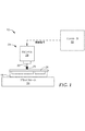
図6に例示するのは回転砥粒ツール300である。回転砥粒ツール300は回転砥粒ツール100と実質的に同様である。但し、回転砥粒ツール300は可撓性フラップ104を含んでいない。
An example of FIG. 6 is the rotary
回転砥粒ツール300はツールシャンク302を含んでいる。ツールシャンク302はツール300に対する回転軸を規定する。ツールシャンク302を、回転機械(例えば、ドリル又はCNC機械)のチャック内に取り付けるように構成してもよい。回転砥粒ツール300は更に、ツールシャンク302と同軸配置にあり、これに取り付けられた円柱状部分314を含んでいる。円柱状部分314は、ツール300の回転軸に垂直な円形断面を伴う砥粒外部表面316を形成している。いくつかの例では、2つ以上の砥粒サイズが砥粒外部表面316の異なる部分に含まれていてもよい。砥粒外部表面316は、本明細書で前述した砥粒コーティングを含んでいてもよい。同じか又は異なる例において、砥粒外部表面316は、やはり本明細書で前述した砥粒フィルムを含んでいてもよい。
The rotary
ツール300を用いてワークピースの表面を研磨した後で、これらの表面砥粒スラリー(例えばCeOスラリー)を用いて磨きをして、表面仕上げを更に改善してもよい。砥粒スラリーを用いる同じか又は異なる例において、ツール300は、異なるレベルの研磨を与える2つ以上のツール300のセットの一部であってもよい。例えば、ツールをより粗いレベルの研磨性からより低いレベルの研磨性へと連続して用いて、表面仕上げを精緻なものにしてもよい。
The surface of the workpiece may be polished with the
図7に例示するのは回転砥粒ツール400である。回転砥粒ツール400は回転砥粒ツール300と実質的に同様であるが、ワークピース(例えば、カバーグラス150)の斜角エッジを研磨するための砥粒外部表面440を含む傾斜表面が付加されている。
An example of FIG. 7 is a rotary
回転砥粒ツール400はツールシャンク402を含んでいる。ツールシャンク402はツール400に対する回転軸を規定する。ツールシャンク402を、回転機械(例えば、ドリル又はCNC機械)のチャック内に取り付けるように構成してもよい。回転砥粒ツール400は更に、ツールシャンク402と同軸配置にありこれに取り付けられた円柱状部分414を含んでいる。円柱状部分414は、ツール400の回転軸に垂直な円形断面を伴う砥粒外部表面416を形成している。いくつかの例では、2つ以上の砥粒サイズが砥粒外部表面416の異なる部分に含まれていてもよい。
The rotary
回転砥粒ツール400は更に第2の砥粒外部表面440を含んでいる。第2の砥粒外部表面440は、砥粒ツール400に対する回転軸に対する傾斜表面を形成する。砥粒外部表面440によって、ワークピース(例えばワークピース150)の内部又は外部の斜角エッジを研磨することが容易になる場合がある。そのため、砥粒外部表面440の形状はワークピースのエッジの所望の仕上げ形状に対応する。他の例では、回転ツールは、ワークピースのエッジの所望の仕上げ形状に対応する異なる幾何学的形状を含んでいてもよい。
The rotary
砥粒外部表面416、440は、本明細書で前述したような砥粒コーティングを含んでいてもよい。同じか又は異なる例において、砥粒外部表面416、440のうちの1つ以上が、やはり本明細書で前述したような砥粒フィルムを含んでいてもよい。
Abrasive grain
ツール400を用いてワークピースの表面を研磨した後で、これらの表面を砥粒スラリー(例えばCeOスラリー)を用いて磨きをして、表面仕上げを更に改善してもよい。砥粒スラリーを用いる同じか又は異なる例において、ツール400は、異なるレベルの研磨を与える2つ以上のツール400のセットの一部であってもよい。例えば、ツールをより粗いレベルの磨耗性からより低いレベルの磨耗性へと連続して用いて、表面仕上げを精緻なものにしてもよい。
After polishing the surfaces of the workpieces with the
図8に例示するのは回転砥粒ツール500である。回転砥粒ツール500は回転砥粒ツール300と実質的に同様であるが、ワークピース(例えば、カバーグラス150)の斜角エッジを研磨するための砥粒外部表面542、544を含む傾斜表面が付加されている。
An example of FIG. 8 is the rotary
回転砥粒ツール500はツールシャンク502を含んでいる。ツールシャンク502はツール500に対する回転軸を規定する。ツールシャンク502を、回転機械(例えば、ドリル又はCNC機械)のチャック内に取り付けるように構成してもよい。回転砥粒ツール500は更に、ツールシャンク502と同軸配置にありこれに取り付けられた円柱状部分514を含んでいる。円柱状部分514は、ツール500の回転軸に垂直な円形断面を伴う砥粒外部表面516を形成している。いくつかの例では、2つ以上の砥粒サイズが砥粒外部表面516の異なる部分に含まれていてもよい。
The rotary
回転砥粒ツール500は更に、円柱状部分514の両側に砥粒外部表面542、544を含んでいる。砥粒外部表面542、544は、砥粒ツール500に対する回転軸に対する傾斜表面を形成している。砥粒外部表面542を、任意的な固定メカニズム205を用いてツールシャンク202に固定してもよい。固定メカニズム205は、ピン、ネジ、リベット、又は他の固定メカニズムを表してもよい。砥粒外部表面542、544によって、ワークピース(例えばワークピース150)の内部又は外部の斜角エッジを研磨することが容易になる場合がある。例えば、外部表面542を、ワークピースの第1の側面上の内部又は外部の斜角エッジを研磨することを容易にするように構成してもよく、一方で、外部表面542を、ワークピースの第2の側面上の内部又は外部の斜角エッジを研磨することを容易にするように構成してもよい。ワークピースの第2の側面はワークピースの第1の側面と向かい合う。そのため、砥粒外部表面542、544の形状はワークピースの所望の仕上げ形状に対応する。他の例では、回転ツールは、ワークピースのエッジの所望の仕上げ形状に対応する異なる幾何学的形状を含んでいてもよい。
The rotary
砥粒外部表面516、542、544は、本明細書で前述したような砥粒コーティングを含んでいてもよい。同じか又は異なる例において、砥粒外部表面516、542、544のうちの1つ以上が、やはり本明細書で前述したような砥粒フィルムを含んでいてもよい。
Abrasive grain
ツール500を用いてワークピースの表面を研磨した後で、これらの表面を砥粒スラリー(例えばCeOスラリー)を用いて磨きをして、表面仕上げを更に改善してもよい。砥粒スラリーを用いる同じか又は異なる例において、ツール500は、異なるレベルの研磨を与える2つ以上のツール500のセットの一部であってもよい。例えば、ツールをより粗いレベルの研磨性からより低いレベルの研磨性へと連続して用いて、表面仕上げを精緻なものにしてもよい。
After polishing the surfaces of the workpieces with the
図9に例示するのは、回転ツールに対する回転軸に垂直な平面表面を形成する砥粒外部表面を含む回転砥粒ツール例である。 Illustrated in FIG. 9 is an example of a rotary abrasive grain tool including an abrasive grain outer surface that forms a flat surface perpendicular to the rotation axis with respect to the rotary tool.
図6に回転砥粒ツール600を例示する。回転砥粒ツール600はツールシャンク602を含んでいる。ツールシャンク602はツール600に対する回転軸を規定する。ツールシャンク602を、回転機械(例えば、ドリル又はCNC機械)のチャック内に取り付けるように構成してもよい。平坦なツールコア606はツールシャンク602に装着され、ツール600に対する回転軸に垂直である。いくつかの例では、平坦なツールコア606とツールシャンク602とは一体の部品に相当してもよい。
FIG. 6 illustrates the rotary
回転砥粒ツール600は平坦な砥粒外部表面650を含んでいる。砥粒外部表面650はツール600に対する回転軸に垂直である。リリーフノッチ552が平坦な砥粒外部表面650の表面内に配置されて、ツール600を用いた研削作業中のくず除去を容易にしている。回転砥粒ツール600はまた、傾斜砥粒面654を含んでいる。傾斜砥粒面654は、ワークピース(例えば、カバーグラス150)の内部又は外部の斜角エッジを研磨することを容易にする。平坦な砥粒外部表面650及び砥粒面654によって、ツール600の回転軸に垂直な円形断面が与えられている。
The rotary
砥粒外部表面650、654は、本明細書で前述したような砥粒コーティングを含んでいてもよい。同じか又は異なる例において、砥粒外部表面650、654は、やはり本明細書で前述したような砥粒フィルムを含んでいてもよい。
Abrasive grain
ツール600を用いてワークピースの表面を研磨した後で、これらの表面を砥粒スラリー(例えばCeOスラリー)を用いて磨きをして、表面仕上げを更に改善してもよい。砥粒スラリーを用いる同じか又は異なる例において、ツール600は、異なるレベルの研磨を与える2つ以上のツール600のセットの一部であってもよい。例えば、ツールをより粗いレベルの研磨性からより低いレベルの研磨性へと連続して用いて、表面仕上げを精緻なものにしてもよい。
After polishing the surfaces of the workpieces with the
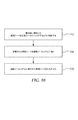
図10は、エポキシ砥粒シートを伴う回転ツールを製造するための技術例を例示するフローチャートである。最初に、部分的に硬化したエポキシを含む砥粒シートを、回転ツールの砥粒面にフィットするように切断する(702)。次に、切断されたシートを回転ツールのコアに巻いて接着する(704)。砥粒が回転ツールのコア上の所定の位置にある時点で、砥粒材のエポキシを更に硬化させて、砥粒材(706)の硬度及び耐久性を増加させる。 FIG. 10 is a flowchart illustrating a technical example for manufacturing a rotary tool with an epoxy abrasive grain sheet. First, a partially cured epoxy-containing abrasive grain sheet is cut to fit the abrasive grain surface of the rotating tool (702). The cut sheet is then wrapped around the core of the rotating tool and glued (704). Once the abrasive grains are in place on the core of the rotating tool, the epoxy in the abrasive grains is further cured to increase the hardness and durability of the abrasive grains (706).
いくつかの特定の例、砥粒材は、前述したようなエポキシ樹脂中に分散された複数のセラミック砥粒凝集体を含んでいてもよい。同じか又は異なる例において、砥粒材のシートは、砥粒材がポリマーフィルム上に堆積され、プライマー層が砥粒複合体層とポリマーフィルムとの間にあってもよい。ポリマーフィルム自体を柔軟層(例えば発泡体)上に、ポリマーフィルムを柔軟層に固定する接着剤を用いて配置してもよい。砥粒材コーティングの組み合わせ、ポリマー材料、及び柔軟材料を次に、回転ツールのコアに適用して、図10の技術により回転ツール上の砥粒面の形状を形成してもよい。 In some specific examples, the abrasive grain material may contain a plurality of ceramic abrasive grain aggregates dispersed in the epoxy resin as described above. In the same or different example, the sheet of abrasive grains may have the abrasive grains deposited on the polymer film and the primer layer between the abrasive complex layer and the polymer film. The polymer film itself may be placed on the flexible layer (eg, foam) with an adhesive that secures the polymer film to the flexible layer. A combination of abrasive grain coatings, a polymeric material, and a flexible material may then be applied to the core of the rotating tool to form the shape of the abrasive grain surface on the rotating tool by the technique of FIG.
動作を以下の詳細な例に関して更に説明する。これらの例は、種々の特定の好ましい例及び技術を更に例示するために示している。しかし当然のことながら、本範囲内に留まりながら多くの変形及び修正を行なってもよい。
実施形態の一覧表
1. 砥粒回転ツールであって、
前記回転ツールに対する回転軸を規定するツールシャンクと、
前記ツールシャンクとは反対側に位置する可撓性の平坦部分と、を備え、
前記可撓性の平坦部分は、前記可撓性の平坦部分の第1の側面上に第1の砥粒外部表面を形成し、前記可撓性の平坦部分の前記第1の側面は、前記ツールシャンクから概ね離れる方向を向き、
前記可撓性の平坦部分は、前記可撓性の平坦部分の第2の側面上に第2の砥粒外部表面を形成し、前記可撓性の平坦部分の前記第2の側面は、概ね前記ツールシャンクの方向を向き、
前記第1の砥粒外部表面が前記ワークピースの前記第1の角部に適用されたときに、前記可撓性の平坦部分は、前記第1の砥粒外部表面を用いて、ワークピースの第1の側面に隣接する第1の角部を、前記回転ツールに対する回転軸に対する複数の角度に渡って、前記可撓性の平坦部分の曲がりによって、容易に研磨し、
前記第2の砥粒外部表面が前記ワークピースの前記第2の角部に適用されたときに、前記可撓性の平坦部分は、前記第2の砥粒外部表面を用いて、前記ワークピースの第2の側面に隣接する第2の角部であって、前記ワークピースの前記第2の側面は、前記ワークピースの前記第1の側面に対向する第2の角部を、前記回転ツールに対する回転軸に対する複数の角度に渡って、前記可撓性の平坦部分の曲がりによって、容易に研磨する、砥粒回転ツール。
2. ツールシャンクに取り付けられた円柱状部分を更に含み、円柱状部分は、回転ツールに対する回転軸を囲む第3の砥粒外部表面を形成し、
円柱状部分は、ワークピースの第1の側面とワークピースの第2の側面との間のワークピースのエッジを、ツールシャンクからの砥粒回転ツールが動作する間に容易に研磨し、
可撓性の平坦部分は、回転ツールに対する回転軸に対する円柱状部分の外径を超えて延びる、実施形態1に記載の砥粒回転ツール。
3. 円柱状部分の第3の砥粒外部表面は、砥粒サイズが互いに異なる少なくとも2つの部分を有する、実施形態2に記載の砥粒回転ツール。
4. 可撓性の平坦部分は第1の可撓性の平坦部分であり、砥粒回転ツールは、ツールシャンクと円柱状部分との間に位置する第2の可撓性の平坦部分を更に含み、
第2の可撓性の平坦部分は、回転ツールに対する回転軸に対する円柱状部分の外径を超えて延び、第2の可撓性の平坦部分は、第2の可撓性の平坦部分の第1の側面上に第4の砥粒外部表面を形成し、第2の可撓性の平坦部分の第1の側面はツールシャンクから概ね離れる方向を向き、第2の可撓性の平坦部分は、第2の可撓性の平坦部分の第2の側面上に第5の砥粒外部表面を形成し、第2の可撓性の平坦部分の第2の側面は、円柱状部分に隣接して、概ねツールシャンクの方向を向き、
第4の砥粒外部表面がワークピースの第1の角部に適用されたときに、第2の可撓性の平坦部分は、第4の砥粒外部表面を用いて、ワークピースの第1の角部を、回転ツールに対する回転軸に対する複数の角度に渡って、第2の可撓性の平坦部分の曲がりによって、容易に研磨し、
第5の砥粒外部表面がワークピースの第2の角部に適用されたときに、第2の可撓性の平坦部分は、第5の砥粒外部表面を用いて、ワークピースの第2の角部を、回転ツールに対する回転軸に対する複数の角度に渡って、第2の可撓性の平坦部分の曲がりによって、容易に研磨する、実施形態2又は実施形態3に記載の砥粒回転ツール。
5. 第1の砥粒外部表面及び第4の砥粒外部表面のそれぞれの砥粒サイズが、第2の砥粒外部表面及び第5の砥粒外部表面のそれぞれの砥粒サイズよりも大きい、実施形態4に記載の砥粒回転ツール。
6. 円柱状部分の第3の砥粒外部表面は、砥粒サイズが互いに異なる少なくとも2つの部分を有する、実施形態5に記載の砥粒回転ツール。
7. 円柱状部分の第3の砥粒外部表面を裏打ちする弾性的圧縮性層を更に含む、実施形態2〜6のいずれかに記載の砥粒回転ツール。
8. 第1の砥粒外部表面と第2の砥粒外部表面のうちの少なくとも一方は、砥粒コーティングを含む、実施形態2〜7のいずれかに記載の砥粒回転ツール。
9. 砥粒回転ツールは、
ガラス、
サファイア、及び
セラミックスからなる群から選択される材料を表面仕上げするように構成されている、先行する実施形態のいずれかに記載の砥粒回転ツール。
10. 第1の砥粒外部表面と第2の砥粒外部表面のうちの少なくとも一方は、砥粒フィルムを含む、先行する実施形態のいずれかに記載の砥粒回転ツール。
11. 第1の砥粒外部表面と第2の砥粒外部表面のうちの少なくとも一方は、ツールの基材にエポキシを用いて固定された砥粒を含む、先行する実施形態のいずれかに記載の砥粒回転ツール。
12. 第1の砥粒外部表面と第2の砥粒外部表面のうちの少なくとも一方の砥粒の粒度は、20マイクロメートル未満である、先行する実施形態のいずれかに記載の砥粒回転ツール。
13. 第1の砥粒外部表面と第2の砥粒外部表面のうちの少なくとも一方の砥粒の粒度は、約10マイクロメートル〜約1マイクロメートルである、先行する実施形態のいずれかに記載の砥粒回転ツール。
14. 第1の砥粒外部表面と第2の砥粒外部表面のうちの少なくとも一方の砥粒の粒度は、約2マイクロメートルである、先行する実施形態のいずれかに記載の砥粒回転ツール。
15. 第1の砥粒外部表面と第2の砥粒外部表面のうちの少なくとも一方の砥粒は、樹脂結合したダイヤモンド砥粒を含む、先行する実施形態のいずれかに記載の砥粒回転ツール。
16. 第1の砥粒外部表面と第2の砥粒外部表面のうちの少なくとも一方の砥粒は、ダイヤモンド凝集体をもたらす、先行する実施形態のいずれかに記載の砥粒回転ツール。
17. 砥粒内のダイヤモンド凝集体対樹脂結合剤の体積比は、3対2よりも大きい、実施形態16に記載の砥粒回転ツール。
18. ダイヤモンド凝集体の平均径は、砥粒粒子の平均径の少なくとも約5倍である、実施形態16又は実施形態17に記載の砥粒回転ツール。
19. 第1の砥粒外部表面と第2の砥粒外部表面のうちの少なくとも一方の砥粒は、トライザクトパターニングされた砥粒を含む、先行する実施形態のいずれかに記載の砥粒回転ツール。
20. 第1の砥粒外部表面と第2の砥粒外部表面のうちの少なくとも一方の砥粒は、
樹脂と、
樹脂中に分散された複数のセラミック砥粒凝集体であって、セラミック砥粒凝集体は、多孔質セラミックマトリックス中に分散された個別砥粒粒子を含み、
多孔質セラミックマトリックスの少なくとも一部分はガラス質セラミック材料を含む、セラミック砥粒凝集体と、
樹脂中に分散された金属粒子と、を含む、先行する実施形態のいずれかに記載の砥粒回転ツール。
21. ワークピースの第1の角部とワークピースの第2の角部は、第1の側面から第2の側面まで延びるワークピース内の孔によって形成される、先行する実施形態のいずれかに記載の砥粒回転ツール。
22. コンピュータ制御された回転ツールホルダとワークピースプラットフォームとを含むCNC機械と、
ワークピースプラットフォームに固定された電子デバイス用の部分的に完成したカバーガラスに相当するワークピースであって、カバーガラスは少なくとも1つの孔を形成する、ワークピースと、
先行する実施形態のいずれかに記載の砥粒回転ツールと、を含む、アセンブリ。
23. 電子デバイス用の部分的に完成したカバーガラス内の孔の表面を研磨するための方法であって、
実施形態1〜21のいずれかに記載の砥粒回転ツールをCNC機械の回転ツールホルダ内に固定することと、
CNC機械を動作させて、CNC機械のワークピースプラットフォームに装着されたカバーガラス内の孔の表面を研磨することと、を含む方法。
The operation will be further described with respect to the following detailed examples. These examples are shown to further illustrate various specific preferred examples and techniques. However, as a matter of course, many modifications and corrections may be made while staying within this range.
List of embodiments 1. Abrasive rotation tool
A tool shank that defines the axis of rotation for the rotation tool,
With a flexible flat portion located on the opposite side of the tool shank,
The flexible flat portion forms a first abrasive grain outer surface on the first side surface of the flexible flat portion, and the first side surface of the flexible flat portion is the said. Turn away from the tool shank,
The flexible flat portion forms a second abrasive grain outer surface on the second side surface of the flexible flat portion, and the second side surface of the flexible flat portion is generally. Orient the tool shank and
When the first abrasive grain outer surface is applied to the first corner of the workpiece, the flexible flat portion uses the first abrasive grain outer surface to form a workpiece. The first corner adjacent to the first side surface is easily polished by bending the flexible flat portion over a plurality of angles with respect to the axis of rotation with respect to the rotation tool.
When the second abrasive grain outer surface is applied to the second corner of the workpiece, the flexible flat portion uses the second abrasive grain outer surface to form the workpiece. The second corner of the work piece is adjacent to the second side surface of the work piece, and the second side surface of the workpiece faces the first side surface of the work piece with the rotation tool. An abrasive grain rotating tool that easily grinds by bending the flexible flat portion over multiple angles with respect to the axis of rotation.
2. Further including a columnar portion attached to the tool shank, the columnar portion forms a third abrasive grain outer surface surrounding the axis of rotation for the rotating tool.
The columnar portion easily polishes the edge of the workpiece between the first side of the workpiece and the second aspect of the workpiece while the abrasive grain rotating tool from the tool shank operates.
The abrasive grain rotating tool according to the first embodiment, wherein the flexible flat portion extends beyond the outer diameter of the columnar portion with respect to the rotating shaft with respect to the rotating tool.
3. 3. The abrasive grain rotation tool according to the second embodiment, wherein the third abrasive grain outer surface of the columnar portion has at least two portions having different abrasive grain sizes.
4. The flexible flat portion is the first flexible flat portion, and the abrasive grain rotation tool further includes a second flexible flat portion located between the tool shank and the columnar portion.
The second flexible flat portion extends beyond the outer diameter of the columnar portion with respect to the axis of rotation with respect to the rotating tool, and the second flexible flat portion is the second of the second flexible flat portion. The outer surface of the fourth abrasive grain is formed on the side surface of 1, the first side surface of the second flexible flat portion faces in a direction substantially away from the tool shank, and the second flexible flat portion faces. , A fifth abrasive grain outer surface is formed on the second side surface of the second flexible flat portion, and the second side surface of the second flexible flat portion is adjacent to the columnar portion. Generally facing the tool shank,
When the fourth abrasive grain outer surface is applied to the first corner of the workpiece, the second flexible flat portion uses the fourth abrasive grain outer surface to make the first of the workpiece. The corners of the are easily polished by bending the second flexible flat section over multiple angles with respect to the axis of rotation with respect to the rotation tool.
When the fifth abrasive grain outer surface is applied to the second corner of the workpiece, the second flexible flat portion uses the fifth abrasive grain outer surface to make a second of the workpiece. The abrasive grain rotating tool according to the second or third embodiment, wherein the corner portion of the above is easily polished by bending of a second flexible flat portion over a plurality of angles with respect to the rotation axis with respect to the rotation tool. ..
5. An embodiment in which the grain size of each of the first abrasive grain outer surface and the fourth abrasive grain outer surface is larger than the respective abrasive grain sizes of the second abrasive grain outer surface and the fifth abrasive grain outer surface. The abrasive grain rotation tool according to 4.
6. The abrasive grain rotation tool according to the fifth embodiment, wherein the third abrasive grain outer surface of the columnar portion has at least two portions having different abrasive grain sizes.
7. The abrasive grain rotation tool according to any one of embodiments 2 to 6, further comprising an elastic compressible layer backing the third abrasive grain outer surface of the columnar portion.
8. The abrasive grain rotation tool according to any one of embodiments 2 to 7, wherein at least one of the first abrasive grain outer surface and the second abrasive grain outer surface includes an abrasive grain coating.
9. Abrasive rotation tool
Glass,
The abrasive grain rotation tool according to any of the preceding embodiments, which is configured to surface finish a material selected from the group consisting of sapphire and ceramics.
10. The abrasive grain rotation tool according to any of the preceding embodiments, wherein at least one of the first abrasive grain outer surface and the second abrasive grain outer surface comprises an abrasive grain film.
11. The grind according to any of the preceding embodiments, wherein at least one of the first abrasive grain outer surface and the second abrasive grain outer surface comprises abrasive grains fixed to the substrate of the tool with epoxy. Grain rotation tool.
12. The abrasive grain rotation tool according to any of the preceding embodiments, wherein the particle size of at least one of the first abrasive grain outer surface and the second abrasive grain outer surface is less than 20 micrometers.
13. The abrasive according to any of the preceding embodiments, wherein the particle size of at least one of the outer surface of the first abrasive grain and the outer surface of the second abrasive grain is about 10 micrometers to about 1 micrometer. Grain rotation tool.
14. The abrasive grain rotation tool according to any of the preceding embodiments, wherein the particle size of at least one of the first abrasive grain outer surface and the second abrasive grain outer surface is about 2 micrometers.
15. The abrasive grain rotation tool according to any of the preceding embodiments, wherein at least one of the outer surface of the first abrasive grain and the outer surface of the second abrasive grain contains a resin-bonded diamond abrasive grain.
16. The abrasive grain rotation tool according to any of the preceding embodiments, wherein at least one abrasive grain of the first abrasive grain outer surface and the second abrasive grain outer surface results in a diamond agglomerate.
17. The abrasive grain rotation tool according to embodiment 16, wherein the volume ratio of the diamond aggregate to the resin binder in the abrasive grains is larger than 3: 2.
18. The abrasive grain rotation tool according to embodiment 16 or 17, wherein the average diameter of the diamond aggregate is at least about 5 times the average diameter of the abrasive grain particles.
19. The abrasive grain rotation tool according to any of the preceding embodiments, wherein at least one of the first abrasive grain outer surface and the second abrasive grain outer surface comprises trizact-patterned abrasive grains.
20. At least one of the outer surface of the first abrasive grain and the outer surface of the second abrasive grain is
With resin
A plurality of ceramic abrasive grain aggregates dispersed in a resin, wherein the ceramic abrasive grain aggregates contain individual abrasive grain particles dispersed in a porous ceramic matrix.
With ceramic abrasive agglomerates, at least a portion of the porous ceramic matrix contains a vitreous ceramic material.
The abrasive grain rotation tool according to any of the preceding embodiments, comprising metal particles dispersed in a resin.
21. The first corner of the workpiece and the second corner of the workpiece are described in any of the preceding embodiments formed by holes in the workpiece extending from the first side surface to the second side surface. Abrasive rotation tool.
22. CNC machines, including computer-controlled rotating tool holders and workpiece platforms,
A workpiece that corresponds to a partially completed cover glass for an electronic device fixed to a workpiece platform, wherein the cover glass forms at least one hole.
An assembly comprising the abrasive grain rotation tool according to any of the preceding embodiments.
23. A method for polishing the surface of holes in a partially completed cover glass for electronic devices.
Fixing the abrasive grain rotation tool according to any one of embodiments 1 to 21 in the rotation tool holder of the CNC machine, and
A method of operating a CNC machine, including polishing the surface of a hole in a cover glass mounted on the workpiece platform of the CNC machine.

*粒径は従来のレーザー光散乱によって測定した平均値である。
* The particle size is an average value measured by conventional laser light scattering.
試験方法及び調製手順
カバーグラス製造テスト−1
周縁エッジ内部特徴エッジ(孔を含む)を形成するためのスクライビング動作の後の部分的に完成したカバーグラスを用意した。部分的に完成したカバーグラスをCNC機械を用いてエッジ研削して、所望のサイズ及び形状を形成した。研削ステップに続いて、エッジを磨きをして好適な表面仕上げを得た。
Test method and preparation procedure Cover glass manufacturing test-1
Peripheral Edge Internal Features Partially completed cover glass after scribing to form edges (including holes) was prepared. The partially completed cover glass was edge ground using a CNC machine to form the desired size and shape. Following the grinding step, the edges were polished to obtain a suitable surface finish.
カバーグラス製造テスト−2
周縁エッジ内部特徴エッジ(孔を含む)を形成するためのスクライビング動作の後の部分的に完成したカバーグラスを用意した。部分的に完成したカバーグラスをCNC機械を用いてエッジ研削して、所望のサイズ及び形状を形成した。エッジ研削されたカバーグラスを次にCNC機械を用いて研磨して、研削されたエッジの表面仕上げを改善した。研磨ステップの後に、エッジを磨きをして好適な表面仕上げを得た。
Cover glass manufacturing test-2
Peripheral Edge Internal Features Partially completed cover glass after scribing to form edges (including holes) was prepared. The partially completed cover glass was edge ground using a CNC machine to form the desired size and shape. The edge-ground cover glass was then polished using a CNC machine to improve the surface finish of the ground edges. After the polishing step, the edges were polished to obtain a suitable surface finish.
表1に、カバーグラス製造テスト−1及びカバーグラス製造テスト−2の比較を示す。
砥粒有効性テスト
スクライビング及び粗い研削作業の後の部分的に完成したカバーグラスを用意した。カバーガラス材料はGorilla(商標)ガラス3(Corning(商標))である。部分的に完成したカバーグラスをCNC機械を用いてエッジ研削して、所望のサイズ及び形状を形成した。エッジ研削されたカバーグラスを次に、CNC機械及び円柱状砥粒ツールを用いて研磨して、研削されたエッジの表面仕上げを改善する。異なるダイヤモンド砥粒組成物の表面仕上げを比べて、異なる砥粒組成物の有効性を評価した。
Abrasive grain effectiveness test A partially completed cover glass was prepared after scribing and rough grinding work. The cover glass material is Gorilla ™ Glass 3 (Corning ™). The partially completed cover glass was edge ground using a CNC machine to form the desired size and shape. The edge-ground cover glass is then polished using a CNC machine and a columnar abrasive grain tool to improve the surface finish of the ground edges. The effectiveness of the different abrasive grain compositions was evaluated by comparing the surface finishes of the different diamond abrasive grain compositions.
表2に、砥粒有効性テストを用いて評価した異なる砥粒組成物の比較を示す。
表2に示すように、サンプルCはサンプルAよりもはるかに高いレベルの材料除去を示した。サンプルCは、砥粒サイズが小さく、サンプルBとほぼ同じレベルの材料除去であった。しかし、サンプルBは、表面仕上げ粗さが、サンプルA及びサンプルCと比べて高かった。これらの結果から、サンプルCは、ほぼサンプルAの表面仕上げ品質を示し、一方でほぼサンプルBの材料除去速度を維持している。 As shown in Table 2, Sample C showed a much higher level of material removal than Sample A. Sample C had a small abrasive grain size and had almost the same level of material removal as Sample B. However, the surface finish roughness of sample B was higher than that of sample A and sample C. From these results, sample C shows almost the surface finish quality of sample A, while maintaining the material removal rate of sample B.
サンプルCは砥粒サイズが、疑集体サイズと比べて相対的に高い。詳細には、サンプルCに対する砥粒サイズ対疑集体サイズの比は10対1である。他の例では、砥粒サイズ対疑集体サイズの比として、15対1以下、12.5対1以下、10対1以下、しかし約3対1以上は、同様にカバーグラスのエッジ研削に対して特に有用な場合がある。 The abrasive grain size of sample C is relatively large compared to the suspicious particle size. Specifically, the ratio of abrasive grain size to suspected particle size to sample C is 10: 1. In another example, the ratio of abrasive grain size to suspected particle size is 15: 1 or less, 12.5: 1 or less, 10: 1 or less, but about 3: 1 or more, similarly for edge grinding of cover glass. May be particularly useful.
本開示の種々の例について説明してきた。これらの及び他の実施例は、以下の特許請求の範囲内である。 Various examples of the present disclosure have been described. These and other examples are within the scope of the following claims.
Claims (3)
前記回転ツールに対する回転軸を規定するツールシャンクと、
前記ツールシャンクとは反対側に位置する可撓性の平坦部分と、を備え、
前記可撓性の平坦部分は、前記可撓性の平坦部分の第1の側面上に第1の砥粒外部表面を形成し、前記可撓性の平坦部分の前記第1の側面は、前記ツールシャンクから概ね離れる方向を向き、
前記可撓性の平坦部分は、前記可撓性の平坦部分の第2の側面上に第2の砥粒外部表面を形成し、前記可撓性の平坦部分の前記第2の側面は、概ね前記ツールシャンクの方向を向き、
前記可撓性の平坦部分は、前記第1及び第2の砥粒外部表面を含む、重ならない可撓性フラップのセットを含み、
前記第1の砥粒外部表面がワークピースの第1の側面に隣接する第1の角部に適用されたときに、前記可撓性の平坦部分は、前記第1の砥粒外部表面を用いて、前記第1の角部を、前記回転ツールに対する前記回転軸に対する複数の角度に渡って、前記可撓性の平坦部分の曲がりによって、容易に研磨し、
前記第2の砥粒外部表面が前記ワークピースの前記第1の側面に対向する第2の側面に隣接する第2の角部に適用されたときに、前記可撓性の平坦部分は、前記第2の砥粒外部表面を用いて、前記第2の角部を、前記回転ツールに対する前記回転軸に対する複数の角度に渡って、前記可撓性の平坦部分の曲がりによって、容易に研磨する、砥粒回転ツール。 Abrasive rotation tool
A tool shank that defines the axis of rotation for the rotation tool,
With a flexible flat portion located on the opposite side of the tool shank,
The flexible flat portion forms a first abrasive grain outer surface on the first side surface of the flexible flat portion, and the first side surface of the flexible flat portion is the said. Turn away from the tool shank,
The flexible flat portion forms a second abrasive grain outer surface on the second side surface of the flexible flat portion, and the second side surface of the flexible flat portion is generally. Orient the tool shank and
The flexible flat portion comprises a set of non-overlapping flexible flaps including the first and second abrasive grain outer surfaces.
When applied to the first corner portion adjacent to the first side of the first abrasive outer surface side Kupisu, flat portion of the flexible, using the first abrasive outer surface Te, the first corner, over a plurality of angles relative to the rotational axis relative to the rotary tool, the bending of the flat portion of the flexible, easily polished,
When the second abrasive grain outer surface is applied to a second corner adjacent to a second side surface of the workpiece facing the first side surface, the flexible flat portion is said to be said. using the second abrasive outer surface, a front Stories second corner, over a plurality of angles relative to the rotational axis relative to the rotary tool, the bending of the flat portion of the flexible, easily polished , Abrasive rotation tool.
前記円柱状部分は、前記ワークピースの前記第1の側面と前記ワークピースの前記第2の側面との間の前記ワークピースのエッジを、前記ツールシャンクからの前記砥粒回転ツールが動作する間に容易に研磨し、
前記可撓性の平坦部分は、前記回転ツールに対する前記回転軸に対する前記円柱状部分の外径を超えて延びる、請求項1に記載の砥粒回転ツール。 Further comprising a columnar portion attached to the tool shank, the columnar portion forms a third abrasive grain outer surface surrounding the rotation axis with respect to the rotation tool.
The columnar portion is formed on the edge of the workpiece between the first side surface of the workpiece and the second side surface of the workpiece while the abrasive grain rotating tool from the tool shank operates. Easy to polish and
The abrasive grain rotating tool according to claim 1, wherein the flexible flat portion extends beyond the outer diameter of the columnar portion with respect to the rotating shaft with respect to the rotating tool.
前記ワークピースプラットフォームに固定された電子デバイス用の部分的に完成したカバーガラスに相当するワークピースであって、前記カバーガラスは少なくとも1つの孔を形成する、ワークピースと、
請求項1又は2に記載の砥粒回転ツールと、を備えている、アセンブリ。 CNC machines with computer-controlled rotating tool holders and workpiece platforms,
A workpiece corresponding to a partially completed cover glass for an electronic device fixed to the work piece platform, wherein the cover glass forms at least one hole.
An assembly comprising the abrasive grain rotating tool according to claim 1 or 2.
Applications Claiming Priority (3)
| Application Number | Priority Date | Filing Date | Title |
|---|---|---|---|
| US201562215646P | 2015-09-08 | 2015-09-08 | |
| US62/215,646 | 2015-09-08 | ||
| PCT/US2016/050350 WO2017044403A1 (en) | 2015-09-08 | 2016-09-06 | Flexible abrasive rotary tool |
Publications (3)
| Publication Number | Publication Date |
|---|---|
| JP2018529539A JP2018529539A (en) | 2018-10-11 |
| JP2018529539A5 JP2018529539A5 (en) | 2019-10-17 |
| JP6909793B2 true JP6909793B2 (en) | 2021-07-28 |
Family
ID=58239844
Family Applications (1)
| Application Number | Title | Priority Date | Filing Date |
|---|---|---|---|
| JP2018531304A Active JP6909793B2 (en) | 2015-09-08 | 2016-09-06 | Flexible Abrasive Rotation Tool |
Country Status (7)
| Country | Link |
|---|---|
| US (1) | US10906156B2 (en) |
| EP (1) | EP3347162A4 (en) |
| JP (1) | JP6909793B2 (en) |
| KR (1) | KR102596800B1 (en) |
| CN (1) | CN108025416B (en) |
| TW (1) | TW201722627A (en) |
| WO (1) | WO2017044403A1 (en) |
Families Citing this family (5)
| Publication number | Priority date | Publication date | Assignee | Title |
|---|---|---|---|---|
| DE102017111559B4 (en) | 2017-05-26 | 2023-10-26 | Fraunhofer-Gesellschaft zur Förderung der angewandten Forschung e.V. | Grinding tool and its use for automated post-processing of milled free-form surfaces |
| WO2019229610A1 (en) * | 2018-05-30 | 2019-12-05 | 3M Innovative Properties Company | Abrasive rotary tool |
| WO2020070598A1 (en) * | 2018-10-03 | 2020-04-09 | 3M Innovative Properties Company | Abrasive rotary tool |
| CN112428098B (en) * | 2019-08-26 | 2023-09-15 | 3M创新有限公司 | Polishing tool, assembly comprising the same and method of polishing a substrate |
| CN117102999B (en) * | 2023-09-05 | 2024-04-09 | 无锡市昌亿机床制造有限公司 | Processing equipment with automatic tool setting chuck tool |
Family Cites Families (33)
| Publication number | Priority date | Publication date | Assignee | Title |
|---|---|---|---|---|
| GB624928A (en) | 1942-03-16 | 1949-06-20 | Minnesota Mining & Mfg | Improvements in or relating to flexible abrasive articles in disc form |
| US3103029A (en) | 1961-09-14 | 1963-09-10 | Fred G Valles | Cleaning structures |
| US3955324A (en) | 1965-10-10 | 1976-05-11 | Lindstroem Ab Olle | Agglomerates of metal-coated diamonds in a continuous synthetic resinous phase |
| US4314827A (en) | 1979-06-29 | 1982-02-09 | Minnesota Mining And Manufacturing Company | Non-fused aluminum oxide-based abrasive mineral |
| US4623364A (en) | 1984-03-23 | 1986-11-18 | Norton Company | Abrasive material and method for preparing the same |
| CA1254238A (en) | 1985-04-30 | 1989-05-16 | Alvin P. Gerk | Process for durable sol-gel produced alumina-based ceramics, abrasive grain and abrasive products |
| US4770671A (en) | 1985-12-30 | 1988-09-13 | Minnesota Mining And Manufacturing Company | Abrasive grits formed of ceramic containing oxides of aluminum and yttrium, method of making and using the same and products made therewith |
| US4881951A (en) | 1987-05-27 | 1989-11-21 | Minnesota Mining And Manufacturing Co. | Abrasive grits formed of ceramic containing oxides of aluminum and rare earth metal, method of making and products made therewith |
| US4835912A (en) * | 1987-11-30 | 1989-06-06 | Aleck Block | Abrasive wheel |
| US5405286A (en) * | 1992-08-21 | 1995-04-11 | Dynabrade, Inc. | Flexible sanding/deburring head |
| US5142829A (en) * | 1992-01-31 | 1992-09-01 | Minnesota Minning And Manufacturing Company | Abrasive article |
| US5197998A (en) * | 1992-01-31 | 1993-03-30 | Minnesota Mining And Manufacturing Company | Method of making a folded abrasive article |
| CA2132408A1 (en) * | 1993-09-27 | 1995-03-28 | Robert E. Ward, Sr. | Abrading wheel having individual sheet members |
| US5958794A (en) | 1995-09-22 | 1999-09-28 | Minnesota Mining And Manufacturing Company | Method of modifying an exposed surface of a semiconductor wafer |
| US5851142A (en) * | 1997-03-26 | 1998-12-22 | Unisand Incorporated | Combined grinding and polishing tool |
| US6319108B1 (en) | 1999-07-09 | 2001-11-20 | 3M Innovative Properties Company | Metal bond abrasive article comprising porous ceramic abrasive composites and method of using same to abrade a workpiece |
| US6595842B2 (en) * | 2000-06-07 | 2003-07-22 | Joseph A. Misiura | Abrasive pad and method of making same |
| US6551366B1 (en) | 2000-11-10 | 2003-04-22 | 3M Innovative Properties Company | Spray drying methods of making agglomerate abrasive grains and abrasive articles |
| US6955591B2 (en) | 2002-09-20 | 2005-10-18 | Deware William R | Adjustable abrading tool |
| JP2009247789A (en) | 2008-04-10 | 2009-10-29 | Asahi Kasei Home Products Kk | Cleaner |
| US8671503B2 (en) | 2009-04-10 | 2014-03-18 | 3M Innovative Properties Company | Cleaning sponge |
| US20120017937A1 (en) | 2010-05-21 | 2012-01-26 | 3M Innovative Properties Company | Cleaning kit and method |
| US8540551B2 (en) | 2010-12-15 | 2013-09-24 | Corning Incorporated | Glass edge finish system, belt assembly, and method for using same |
| US8721392B2 (en) | 2011-06-28 | 2014-05-13 | Corning Incorporated | Glass edge finishing method |
| CN202219460U (en) * | 2011-07-21 | 2012-05-16 | 西北工业大学 | Polishing wheel for polishing air inlet and exhaust edges of blades |
| US9375820B2 (en) | 2012-04-16 | 2016-06-28 | Corning Incorporated | Method and system for finishing glass sheets |
| JP2014014905A (en) * | 2012-07-10 | 2014-01-30 | Yuichiro Niizaki | Combination brush |
| US9643292B2 (en) * | 2012-11-16 | 2017-05-09 | James L. Ebert | Single and tandem honing devices |
| JP2014108478A (en) * | 2012-11-30 | 2014-06-12 | Noritake Co Ltd | End surface polishing tool for sheet glass |
| WO2014176202A1 (en) * | 2013-04-25 | 2014-10-30 | Saint-Gobain Abrasives, Inc. | Grinding and polishing tool |
| US9610670B2 (en) * | 2013-06-07 | 2017-04-04 | Apple Inc. | Consumable abrasive tool for creating shiny chamfer |
| KR101933285B1 (en) * | 2013-09-23 | 2018-12-27 | 애플 인크. | Electronic component embedded in ceramic material |
| EP3347165B1 (en) | 2015-09-08 | 2023-08-02 | 3M Innovative Properties Company | Abrasive rotary tool with abrasive agglomerates |
-
2016
- 2016-09-06 CN CN201680051897.8A patent/CN108025416B/en active Active
- 2016-09-06 JP JP2018531304A patent/JP6909793B2/en active Active
- 2016-09-06 KR KR1020187009303A patent/KR102596800B1/en active IP Right Grant
- 2016-09-06 WO PCT/US2016/050350 patent/WO2017044403A1/en active Application Filing
- 2016-09-06 US US15/758,192 patent/US10906156B2/en active Active
- 2016-09-06 EP EP16844924.7A patent/EP3347162A4/en not_active Withdrawn
- 2016-09-07 TW TW105128895A patent/TW201722627A/en unknown
Also Published As
| Publication number | Publication date |
|---|---|
| KR20180050688A (en) | 2018-05-15 |
| WO2017044403A1 (en) | 2017-03-16 |
| US20180250793A1 (en) | 2018-09-06 |
| JP2018529539A (en) | 2018-10-11 |
| CN108025416B (en) | 2021-06-29 |
| US10906156B2 (en) | 2021-02-02 |
| KR102596800B1 (en) | 2023-10-31 |
| EP3347162A1 (en) | 2018-07-18 |
| EP3347162A4 (en) | 2019-05-15 |
| TW201722627A (en) | 2017-07-01 |
| CN108025416A (en) | 2018-05-11 |
Similar Documents
| Publication | Publication Date | Title |
|---|---|---|
| JP6964588B2 (en) | Abrasive rotation tool with abrasive agglomerates | |
| JP6909793B2 (en) | Flexible Abrasive Rotation Tool | |
| KR102252673B1 (en) | Multi-layered polishing pads | |
| US6702650B2 (en) | Porous abrasive article having ceramic abrasive composites, methods of making, and methods of use | |
| KR101870000B1 (en) | Coated abrasive article having rotationally aligned formed ceramic abrasive particles and method of making | |
| JP2016537439A (en) | Ceramic abrasive composite polishing solution | |
| JP2003504218A (en) | Metal bonded abrasive articles containing porous ceramic abrasive composites and methods of polishing workpieces using the same | |
| US10414020B2 (en) | Grindstone and grinding/polishing device using same | |
| CA2902273A1 (en) | A method to provide an abrasive product surface and abrasive products thereof | |
| JP2017530210A (en) | Polishing liquid and method of using the same | |
| US10456888B2 (en) | Abrasive material and production method of abrasive material | |
| CN105690240A (en) | Flexible polishing pad | |
| TWI306048B (en) | ||
| JP2005297165A (en) | Grinder and its manufacturing method |
Legal Events
| Date | Code | Title | Description |
|---|---|---|---|
| RD03 | Notification of appointment of power of attorney |
Free format text: JAPANESE INTERMEDIATE CODE: A7423 Effective date: 20190617 |
|
| RD04 | Notification of resignation of power of attorney |
Free format text: JAPANESE INTERMEDIATE CODE: A7424 Effective date: 20190624 |
|
| A521 | Request for written amendment filed |
Free format text: JAPANESE INTERMEDIATE CODE: A523 Effective date: 20190905 |
|
| A621 | Written request for application examination |
Free format text: JAPANESE INTERMEDIATE CODE: A621 Effective date: 20190905 |
|
| A977 | Report on retrieval |
Free format text: JAPANESE INTERMEDIATE CODE: A971007 Effective date: 20200923 |
|
| A131 | Notification of reasons for refusal |
Free format text: JAPANESE INTERMEDIATE CODE: A131 Effective date: 20201006 |
|
| A521 | Request for written amendment filed |
Free format text: JAPANESE INTERMEDIATE CODE: A523 Effective date: 20210104 |
|
| TRDD | Decision of grant or rejection written | ||
| A01 | Written decision to grant a patent or to grant a registration (utility model) |
Free format text: JAPANESE INTERMEDIATE CODE: A01 Effective date: 20210608 |
|
| A61 | First payment of annual fees (during grant procedure) |
Free format text: JAPANESE INTERMEDIATE CODE: A61 Effective date: 20210705 |
|
| R150 | Certificate of patent or registration of utility model |
Ref document number: 6909793 Country of ref document: JP Free format text: JAPANESE INTERMEDIATE CODE: R150 |