JP7501260B2 - vehicle - Google Patents
vehicle Download PDFInfo
- Publication number
- JP7501260B2 JP7501260B2 JP2020153320A JP2020153320A JP7501260B2 JP 7501260 B2 JP7501260 B2 JP 7501260B2 JP 2020153320 A JP2020153320 A JP 2020153320A JP 2020153320 A JP2020153320 A JP 2020153320A JP 7501260 B2 JP7501260 B2 JP 7501260B2
- Authority
- JP
- Japan
- Prior art keywords
- opening
- closing
- heat exchanger
- air
- vehicle
- Prior art date
- Legal status (The legal status is an assumption and is not a legal conclusion. Google has not performed a legal analysis and makes no representation as to the accuracy of the status listed.)
- Active
Links
- 239000003507 refrigerant Substances 0.000 claims description 41
- 238000001816 cooling Methods 0.000 claims description 38
- 238000010438 heat treatment Methods 0.000 claims description 38
- 239000000498 cooling water Substances 0.000 claims description 25
- 239000007858 starting material Substances 0.000 claims 1
- 238000000034 method Methods 0.000 description 22
- XLYOFNOQVPJJNP-UHFFFAOYSA-N water Substances O XLYOFNOQVPJJNP-UHFFFAOYSA-N 0.000 description 21
- 238000004378 air conditioning Methods 0.000 description 20
- 239000002826 coolant Substances 0.000 description 16
- 230000008569 process Effects 0.000 description 16
- 238000010586 diagram Methods 0.000 description 8
- 230000006870 function Effects 0.000 description 7
- 239000012071 phase Substances 0.000 description 7
- 239000006096 absorbing agent Substances 0.000 description 6
- 238000010521 absorption reaction Methods 0.000 description 6
- 230000009471 action Effects 0.000 description 6
- 230000000694 effects Effects 0.000 description 6
- 239000007791 liquid phase Substances 0.000 description 6
- 230000002787 reinforcement Effects 0.000 description 6
- 238000010257 thawing Methods 0.000 description 6
- 239000002918 waste heat Substances 0.000 description 5
- 230000008859 change Effects 0.000 description 4
- 238000007710 freezing Methods 0.000 description 4
- 230000008014 freezing Effects 0.000 description 4
- 230000007704 transition Effects 0.000 description 4
- 230000007423 decrease Effects 0.000 description 3
- 230000007246 mechanism Effects 0.000 description 3
- 238000012545 processing Methods 0.000 description 3
- 238000004590 computer program Methods 0.000 description 2
- 230000003014 reinforcing effect Effects 0.000 description 2
- 238000012546 transfer Methods 0.000 description 2
- 230000005856 abnormality Effects 0.000 description 1
- 238000004891 communication Methods 0.000 description 1
- 238000005336 cracking Methods 0.000 description 1
- 238000013461 design Methods 0.000 description 1
- 230000007613 environmental effect Effects 0.000 description 1
- 239000007789 gas Substances 0.000 description 1
- 230000001771 impaired effect Effects 0.000 description 1
- 239000000155 melt Substances 0.000 description 1
- 238000002844 melting Methods 0.000 description 1
- 230000008018 melting Effects 0.000 description 1
- 238000012986 modification Methods 0.000 description 1
- 230000004048 modification Effects 0.000 description 1
- 230000001172 regenerating effect Effects 0.000 description 1
- 230000001052 transient effect Effects 0.000 description 1
Images


Classifications
-
- B—PERFORMING OPERATIONS; TRANSPORTING
- B60—VEHICLES IN GENERAL
- B60H—ARRANGEMENTS OF HEATING, COOLING, VENTILATING OR OTHER AIR-TREATING DEVICES SPECIALLY ADAPTED FOR PASSENGER OR GOODS SPACES OF VEHICLES
- B60H1/00—Heating, cooling or ventilating [HVAC] devices
- B60H1/22—Heating, cooling or ventilating [HVAC] devices the heat being derived otherwise than from the propulsion plant
-
- B—PERFORMING OPERATIONS; TRANSPORTING
- B60—VEHICLES IN GENERAL
- B60H—ARRANGEMENTS OF HEATING, COOLING, VENTILATING OR OTHER AIR-TREATING DEVICES SPECIALLY ADAPTED FOR PASSENGER OR GOODS SPACES OF VEHICLES
- B60H1/00—Heating, cooling or ventilating [HVAC] devices
- B60H1/32—Cooling devices
-
- B—PERFORMING OPERATIONS; TRANSPORTING
- B60—VEHICLES IN GENERAL
- B60K—ARRANGEMENT OR MOUNTING OF PROPULSION UNITS OR OF TRANSMISSIONS IN VEHICLES; ARRANGEMENT OR MOUNTING OF PLURAL DIVERSE PRIME-MOVERS IN VEHICLES; AUXILIARY DRIVES FOR VEHICLES; INSTRUMENTATION OR DASHBOARDS FOR VEHICLES; ARRANGEMENTS IN CONNECTION WITH COOLING, AIR INTAKE, GAS EXHAUST OR FUEL SUPPLY OF PROPULSION UNITS IN VEHICLES
- B60K11/00—Arrangement in connection with cooling of propulsion units
- B60K11/02—Arrangement in connection with cooling of propulsion units with liquid cooling
- B60K11/04—Arrangement or mounting of radiators, radiator shutters, or radiator blinds
Landscapes
- Engineering & Computer Science (AREA)
- Mechanical Engineering (AREA)
- Physics & Mathematics (AREA)
- Thermal Sciences (AREA)
- Chemical & Material Sciences (AREA)
- Combustion & Propulsion (AREA)
- Transportation (AREA)
- Cooling, Air Intake And Gas Exhaust, And Fuel Tank Arrangements In Propulsion Units (AREA)
- Air-Conditioning For Vehicles (AREA)
Description
本開示は、車両に関する。 This disclosure relates to vehicles.
電動車両では、その動力源であるモータを冷却水が循環することによりモータが冷却される。そのため、電動車両には、モータの冷却水を冷却するためのラジエータが搭載されている。一方、電動車両とエンジン車両とを比較すると、電動車両の動力源であるモータの発熱量は、エンジン車両の動力源であるエンジンの発熱量よりも少ない。そのため、モータの冷却水を冷却するためのラジエータに供給すべき空気量は、エンジンの冷却水を冷却するためのラジエータに供給すべき空気量よりも少ない。そこで、従来の電動車両では、例えば下記の特許文献1に記載されるように、車両前方の空気をラジエータに導入するためのグリル開口部の開度がエンジン車両のグリル開口部の開度よりも小さく設定されることがある。具体的には、特許文献1に記載の車両では、ラジエータの下半分にのみ対向するようにグリル開口部が形成されている。この車両には、グリル開口部から導入される空気をラジエータに導くダクトが形成されている。ダクトは、その流路断面積がグリル開口部からラジエータに向かって徐々に拡大するように形成されている。特許文献1に記載の車両のようにグリル開口部を小さくすることにより車両の空力性能を向上させることができるため、車両の航続距離を延ばすこと等が可能となる。
In an electric vehicle, the motor is cooled by circulating cooling water through the motor, which is the power source of the electric vehicle. Therefore, an electric vehicle is equipped with a radiator for cooling the motor's cooling water. On the other hand, when comparing an electric vehicle with an engine vehicle, the amount of heat generated by the motor, which is the power source of the electric vehicle, is less than the amount of heat generated by the engine, which is the power source of the engine vehicle. Therefore, the amount of air to be supplied to the radiator for cooling the motor's cooling water is less than the amount of air to be supplied to the radiator for cooling the engine's cooling water. Therefore, in a conventional electric vehicle, as described in, for example,
ところで、特許文献1に記載のダクトでは、上下方向においてグリル開口部に近い部分の圧力よりも、上下方向においてグリル開口部から遠い部分の圧力の方が高くなり易い。その結果、ラジエータにおいてグリル開口部に近い部分を流れる空気の風量よりも、グリル開口部から遠い部分を流れる空気の風量の方が少なくなる。このような空気の風量分布のばらつきは、ラジエータの熱交換効率を低下させる要因となるため、好ましくない。
However, in the duct described in
本開示は、こうした実情に鑑みてなされたものであり、その目的は、熱交換器の熱交換効率を高めることが可能な車両を提供することにある。 This disclosure has been made in light of these circumstances, and its purpose is to provide a vehicle that can improve the heat exchange efficiency of the heat exchanger.
上記課題を解決する車両は、グリル開口部(2)から導入される空気と熱交換を行う熱交換器(5,6,10,11)と、開閉部(51)の開閉動作により熱交換器に供給される空気の風量を変化させることが可能な開閉装置(8)と、開閉装置を制御する制御部(82)と、を備える。グリル開口部の開口面積は、熱交換器の前面投影面積よりも小さい。開閉装置は、開閉部として、同開閉装置の第1部位(A13,A14)を開閉する第1開閉部(512)と、同開閉装置において第1部位よりもグリル開口部から遠い第2部位(A11,A12)を開閉する第2開閉部(511)と、を有する。熱交換器として、車両の第1発熱体を冷却する冷却水と空気とで熱交換を行うラジエータ(11)と、ヒートポンプ装置(30)を循環する冷媒と空気とで熱交換を行う第1熱交換部(10A)、及び第1発熱体とは別の第2発熱体を冷却する冷却水と空気とで熱交換を行う第2熱交換部(10B)を有する室外熱交換器(10)と、を有する。室外熱交換器において第1熱交換部が開閉装置の第1部位に対向して配置されるとともに、第2熱交換部が開閉装置の第2部位に対向して配置されている。制御部は、第2部位の開度よりも第1部位の開度の方が小さくなるように第1開閉部及び第2開閉部を動作させ、第2発熱体の冷却が要求されていない場合、第1開閉部を開状態に設定する一方、第2開閉部を閉状態に設定する。
上記課題を解決する他の車両は、グリル開口部(2)から導入される空気と熱交換を行う熱交換器(5,6,10,11)と、開閉部(51)の開閉動作により熱交換器に供給される空気の風量を変化させることが可能な開閉装置(8)と、開閉装置を制御する制御部(82)と、を備える。グリル開口部の開口面積は、熱交換器の前面投影面積よりも小さい。開閉装置は、開閉部として、同開閉装置の第1部位(A13,A14)を開閉する第1開閉部(512)と、同開閉装置において第1部位よりもグリル開口部から遠い第2部位(A11,A12)を開閉する第2開閉部(511)と、を有する。熱交換器として、ヒートポンプ装置(30)を循環する冷媒と空気とで熱交換を行う室外熱交換器(6)を有する。制御部は、第2部位の開度よりも第1部位の開度の方が小さくなるように第1開閉部及び第2開閉部を動作させ、ヒートポンプ装置において室外熱交換器が空気の熱を冷媒に吸収させる吸熱器として動作しているとき、第1開閉部が閉状態に設定されており、且つ第2開閉部が開状態に設定されている第1状態と、第1開閉部が開状態に設定されており、且つ第2開閉部が閉状態に設定されている第2状態とを交互に切り替える。
The vehicle that solves the above problem includes a heat exchanger (5, 6, 10, 11) that exchanges heat with air introduced from a grill opening (2), an opening/closing device (8) that can change the volume of air supplied to the heat exchanger by opening and closing an opening/closing part (51), and a control part (82) that controls the opening/closing device. The opening area of the grill opening is smaller than the frontal projection area of the heat exchanger. The opening/closing device has, as the opening/closing part, a first opening/closing part (512) that opens and closes a first portion (A13, A14) of the opening/closing device, and a second opening/closing part (511) that opens and closes a second portion (A11, A12) of the opening/closing device that is farther from the grill opening than the first portion. The heat exchanger includes an outdoor heat exchanger (10) having a radiator (11) for exchanging heat between air and a coolant for cooling a first heating element of the vehicle, a first heat exchange section (10A) for exchanging heat between air and a refrigerant circulating in a heat pump device (30), and a second heat exchange section (10B) for exchanging heat between air and a coolant for cooling a second heating element different from the first heating element. In the outdoor heat exchanger, the first heat exchange section is disposed opposite a first portion of the opening/closing device, and the second heat exchange section is disposed opposite a second portion of the opening/closing device. The control section operates the first opening/closing section and the second opening/closing section so that the opening degree of the first portion is smaller than the opening degree of the second portion , and when cooling of the second heating element is not required, sets the first opening/closing section to an open state and sets the second opening/closing section to a closed state .
Another vehicle that solves the above problem includes a heat exchanger (5, 6, 10, 11) that exchanges heat with air introduced from a grill opening (2), an opening/closing device (8) that can change the amount of air supplied to the heat exchanger by opening and closing an opening/closing part (51), and a control part (82) that controls the opening/closing device. The opening area of the grill opening is smaller than the front projection area of the heat exchanger. The opening/closing device has, as the opening/closing part, a first opening/closing part (512) that opens and closes a first part (A13, A14) of the opening/closing device, and a second opening/closing part (511) that opens and closes a second part (A11, A12) of the opening/closing device that is farther from the grill opening than the first part. The heat exchanger has an outdoor heat exchanger (6) that exchanges heat between a refrigerant circulating in a heat pump device (30) and air. The control unit operates the first opening/closing unit and the second opening/closing unit so that the opening degree of the first unit is smaller than the opening degree of the second unit, and when the outdoor heat exchanger in the heat pump device is operating as a heat sink that absorbs heat of the air into the refrigerant, alternately switches between a first state in which the first opening/closing unit is set to a closed state and the second opening/closing unit is set to an open state, and a second state in which the first opening/closing unit is set to an open state and the second opening/closing unit is set to a closed state.
この構成のように、開閉装置の第2部位の開度よりも第1部位の開度の方が小さくなることにより、開閉装置の第1部位よりも第2部位の方が、空気が流れ易くなる。これにより、熱交換器においてグリル開口部の近くに配置される部分における空気の圧力を高くなる方向に変化させることができる一方、グリル開口部の遠くに配置される部分における空気の圧力を低くなる方向に変化させることができる。このように開閉装置の開度の偏りにより空気の圧力を部分的に変化させることで、グリル開口部の位置に起因する空気の圧力の偏りを軽減することができる。その結果、熱交換器に供給される空気の風量のばらつきを軽減することができるため、熱交換器の熱交換効率を高めることが可能となる。 In this configuration, the opening degree of the first portion of the opening/closing device is smaller than the opening degree of the second portion, so that air flows more easily through the second portion of the opening/closing device than through the first portion. This makes it possible to change the air pressure in the portion of the heat exchanger that is located near the grill opening in a higher direction, while changing the air pressure in the portion that is located farther from the grill opening in a lower direction. By partially changing the air pressure by varying the opening degree of the opening/closing device in this way, it is possible to reduce the bias in air pressure caused by the position of the grill opening. As a result, it is possible to reduce the variation in the amount of air supplied to the heat exchanger, thereby making it possible to increase the heat exchange efficiency of the heat exchanger.
なお、上記手段、特許請求の範囲に記載の括弧内の符号は、後述する実施形態に記載の具体的手段との対応関係を示す一例である。 Note that the symbols in parentheses in the above means and claims are examples showing the correspondence with the specific means described in the embodiments described below.
本開示の車両によれば、熱交換器の熱交換効率を高めることが可能となる。 The vehicle disclosed herein makes it possible to increase the heat exchange efficiency of the heat exchanger.
以下、車両の実施形態について図面を参照しながら説明する。説明の理解を容易にするため、各図面において同一の構成要素に対しては可能な限り同一の符号を付して、重複する説明は省略する。
<第1実施形態>
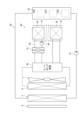
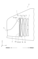
図1に示される車両Cは、モータを動力源として走行する、いわゆる電動車両である。車両Cのボディ1の前方にはグリル開口部2が設けられている。グリル開口部2は車両ボディ1の前方の空気をラジエータ5及び室外熱交換器6に供給するために設けられている。グリル開口部2から導入される空気は導風ダクト4を通じてラジエータ5及び室外熱交換器6に供給される。ラジエータ5は、車両Cのパワーユニットを冷却するための冷却回路の構成要素であって、冷却回路を循環する冷却水と、グリル開口部2から導入される空気とを熱交換させることにより冷却水の放熱を行う。パワーユニットには、車両Cの動力源であるモータ、並びにモータを駆動させるためのバッテリやインバータ装置等が含まれる。室外熱交換器6は、車両Cに搭載される空調装置に設けられるヒートポンプ装置の構成要素であって、ヒートポンプ装置を循環する冷媒と、グリル開口部2から導入される空気とを熱交換させることによりコンデンサ又は吸熱器として動作する。ラジエータ5は室外熱交換器6よりも車両前方に配置されている。室外熱交換器6の空気流れ方向の下流には送風機7が設けられている。送風機7は、例えば車両Cの停車時にラジエータ5及び室外熱交換器6に空気を供給するために設けられている。本実施形態では、ラジエータ5及び室外熱交換器6が熱交換器に相当する。
Hereinafter, an embodiment of a vehicle will be described with reference to the drawings. In order to facilitate understanding of the description, the same components in the drawings are denoted by the same reference numerals as much as possible, and duplicated description will be omitted.
First Embodiment
The vehicle C shown in FIG. 1 is a so-called electric vehicle that runs using a motor as a power source. A
ラジエータ5の車両前方にはシャッタ装置8が対向するように配置されている。シャッタ装置8は、グリル開口部2から導入される空気がラジエータ5及び室外熱交換器6に流れることが可能な開状態と、それらへの空気の流れが遮断されている閉状態とに切り替え可能に構成されている。シャッタ装置8は、例えば車両Cの高速走行時に閉状態になることにより車両Cの空力性能を向上させる。本実施形態では、シャッタ装置8が開閉装置に相当する。
A
次に、ラジエータ5が用いられる冷却回路、及び室外熱交換器6が用いられるヒートポンプ装置のそれぞれの概略構成について説明する。
図2に示されるように、冷却回路20には、ラジエータ5、ポンプ21、及び発熱体22が設けられている。冷却回路20では、それらの要素を冷却水が循環している。ラジエータ5は、その内部を流れる冷却水と、その外部を流れる空気とを熱交換させることにより冷却水を冷却する。ポンプ21は、ラジエータ5により冷却された冷却水を吸入して発熱体22に吐出する。このポンプ21の駆動により冷却回路20を冷却水が循環している。ポンプ21は、電力の供給に基づき駆動する電動式のポンプである。発熱体22には、車両Cのパワーユニットを構成するモータ220やインバータ装置221、バッテリ222等が含まれている。インバータ装置221は、バッテリ222に充電されている直流電力を交流電力に変換してモータ220に供給するとともに、モータ220の回生動作により発電される交流電力を直流電力に変換してバッテリ222に充電する。モータ220、インバータ装置221、及びバッテリ222には、ポンプ21から吐出される冷却水が流れる。この冷却水がモータ220等の熱を吸収することにより、それらが冷却される。モータ220等の熱を吸収することにより温度の上昇した冷却水はラジエータ5に供給されることで再度冷却される。
Next, a schematic configuration of a cooling circuit in which the
As shown in FIG. 2, the
ヒートポンプ装置30は車両Cの空調装置40の構成要素である。ヒートポンプ装置30には、室外熱交換器6、水冷コンデンサ31、及びエバポレータ32が設けられている。ヒートポンプ装置30では、それらの要素を冷媒が循環している。ヒートポンプ装置30は、空調装置40が冷房モードで動作している場合と、空調装置40が暖房モードで動作している場合とで冷媒の流れ状態を変化させることにより、車室内の冷房と暖房とを実現する。
The
具体的には、空調装置40が冷房モードで動作している場合、ヒートポンプ装置30は室外熱交換器6及びエバポレータ32に冷媒を循環させる。このとき室外熱交換器6はコンデンサとして動作する。すなわち、室外熱交換器6は、その内部を流れる冷媒と、その外部を流れる空気とを熱交換させることにより冷媒を冷却する。室外熱交換器6により冷却されることで生成される高圧の液相冷媒は、ヒートポンプ装置30に設けられる減圧弁を通じて減圧させられることにより低圧の液相冷媒に遷移した後、エバポレータ32に供給される。エバポレータ32は、その内部を流れる冷媒と、空調装置40の空調ダクト41を流れる空気とを熱交換させることにより、空調ダクト41内の空気を冷却する。この空気が空調ダクト41を通じて車室内に送風されることにより車室内の冷房が行われる。エバポレータ32では、空気との熱交換により低圧の液相冷媒が低圧の気相冷媒に遷移する。この低圧の気相冷媒は、ヒートポンプ装置30に設けられるポンプにより圧縮されることにより高温及び高圧の気相冷媒に遷移した後、室外熱交換器6に供給されることで再度冷却される。
Specifically, when the
一方、空調装置40が暖房モードで動作している場合、ヒートポンプ装置30は室外熱交換器6及び水冷コンデンサ31に冷媒を循環させる。このとき室外熱交換器6は吸熱器として動作する。すなわち、室外熱交換器6は、その内部を流れる冷媒と、その外部を流れる空気とを熱交換させることにより冷媒を加熱する。室外熱交換器6により加熱されることで生成される低圧の気相冷媒は、ヒートポンプ装置30に設けられるポンプを通じて高温及び高圧の気相冷媒に遷移した後、水冷コンデンサ31に供給される。水冷コンデンサ31では、ヒートポンプ装置30から供給される高温及び高圧の気相冷媒と、空調装置40の冷却水回路42を流れる冷却水とを熱交換させることにより冷却水を加熱する。冷却水回路42には、水冷コンデンサ31に加え、空調装置40のヒータコア43、及びポンプ44が設けられている。ポンプ44は冷却水回路42において冷却水を循環させる。ヒータコア43は、その内部を流れる冷却水と、空調ダクト41を流れる空気とを熱交換させることにより、空調ダクト41内を流れる空気を加熱する。この空気が空調ダクト41を通じて車室内に送風されることにより車室内の暖房が行われる。水冷コンデンサ31では、冷却水との熱交換により高温及び高圧の気相冷媒が高圧の液相冷媒に遷移する。この高圧の液相冷媒は、ヒートポンプ装置30に設けられる減圧弁を通じて減圧させられることにより低圧の液相冷媒に遷移した後、室外熱交換器6に供給されることで再度加熱される。
On the other hand, when the
次に、シャッタ装置8の概略構成について説明する。
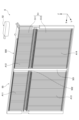
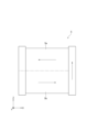
図3に示されるように、シャッタ装置8は、フレーム50と、複数のブレード51と、モータ52とを備えている。
フレーム50は、矩形枠状に形成されたフレーム本体部500と、フレーム本体部500の内側に十字状に配置される縦フレーム補強部501及び横フレーム補強部502とを有している。フレーム本体部500の内側の空間には、図1に示されるグリル開口部2から導入される空気が矢印Yで示される方向に流れる。
Next, the schematic configuration of the
As shown in FIG. 3, the
The
以下では、フレーム本体部500の長手方向Xを左右方向とも称し、フレーム本体部500の短手方向Zを上下方向とも称する。また、左右方向X及び上下方向Zの両方に直交する矢印Yで示される方向を「空気流れ方向Y」とも称する。
縦フレーム補強部501はフレーム本体部500を補強するために設けられている。横フレーム補強部502はフレーム本体部500を補強し、且つブレード51を保持するために設けられている。縦フレーム補強部501及び横フレーム補強部502によりフレーム本体部500の内側の空間が4つの開口領域A11~A14に区画されている。
Hereinafter, the longitudinal direction X of the frame
The vertical
なお、以下では、4つの開口領域A11~A14のうち、横フレーム補強部502よりも上方に配置される2つの開口領域A11,A12を「上側開口領域A11,A12」と称し、横フレーム補強部502よりも下方に配置される2つの開口領域A13,A14を「下側開口領域A13,A14」と称する。
In the following, of the four opening areas A11 to A14, the two opening areas A11 and A12 located above the horizontal
図1に示されるように、下側開口領域A13,A14の略下半分はグリル開口部2に対向するように位置している。グリル開口部2の開口面積は、ラジエータ5及び室外熱交換器6のそれぞれの前面投影面積よりも小さい。本実施形態では、下側開口領域A13,A14が第1部位に相当する。また、上側開口領域A11,A12が、第1部位よりもグリル開口部2から遠い第2部位に相当する。
As shown in FIG. 1, approximately the lower half of the lower opening areas A13 and A14 is positioned to face the
ラジエータ5の上部5a及び室外熱交換器6の上部6aはシャッタ装置8の上側開口領域A11,A12に対向するように配置されている。ラジエータ5において上部5aを除く部位である下部5b、及び室外熱交換器6において上部6aを除く部位である下部6bはシャッタ装置8の下側開口領域A13,A14に対向するように配置されている。なお、図1のラジエータ5に記載される二点鎖線はラジエータ5の上部5aと下部5bとの境界部分を示している。同様に、室外熱交換器6に記載される二点鎖線は室外熱交換器6の上部6aと下部6bとの境界部分を示している。
The
図3に示されるように、複数のブレード51は、フレーム50の4つの開口領域A11~A14にそれぞれ配置されている。4つの開口領域A11~A14において、複数のブレード51は上下方向Zに長手方向を有するように配置されるとともに、左右方向Xに並べて配置されている。以下では、便宜上、複数のブレード51のうち、フレーム本体部500の上側開口領域A11,A12に配置されるブレード51を「上側ブレード511」と称し、下側開口領域A13,A14に配置されるブレード51を「下側ブレード512」と称する。本実施形態では、ブレード51が開閉部に相当し、下側ブレード512が第1開閉部に相当し、上側ブレード511が第2開閉部に相当する。
As shown in FIG. 3, the
モータ52は、フレーム本体部500の上面の一端部にねじ等により固定される。モータ52は、図示しないリンク機構を介して上側ブレード511及び下側ブレード512に回転力を付与することにより各ブレード511,512を回転させる。なお、本実施形態のシャッタ装置8は上側ブレード511及び下側ブレード512のそれぞれの開度を独立して制御可能となっている。
The
このシャッタ装置8では、上側ブレード511及び下側ブレード512が開状態である場合には、各上側ブレード511の間に隙間が形成されるとともに、各下側ブレード512の間に隙間が形成されるため、それらの隙間を通じて、グリル開口部2から導入される空気がラジエータ5及び室外熱交換器6に供給される。一方、上側ブレード511及び下側ブレード512が閉状態であるとき、各ブレード511,512の間の隙間が閉塞されるため、ラジエータ5及び室外熱交換器6への空気の供給が遮断される。また、上側ブレード511及び下側ブレード512のそれぞれの開度が独立して制御されることにより、図1に示されるラジエータ5の上部5a及び下部5bにそれぞれ供給される空気量、及び室外熱交換器6の上部6a及び下部6bにそれぞれ供給される空気量を個別に調整することが可能である。
In this
次に、車両Cの電気的な構成について説明する。
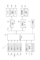
図4に示されるように、車両Cには、その走行状態や冷却回路20の状態、ヒートポンプ装置30の状態、車両Cの内外の環境状態等を検出するための各種センサ60が設けられている。センサ60には、外気温センサ61、車速センサ62、冷媒圧センサ63、水温センサ64、内気温センサ65、外気温センサ66等が含まれている。外気温センサ61は、車両Cの外部の空気である外気の温度を検出する。車速センサ62は、車両Cの走行速度である車速を検出する。冷媒圧センサ63は、ヒートポンプ装置30において室外熱交換器6から流出する冷媒の圧力を検出する。水温センサ64は、冷却回路20において発熱体22から流出する冷却水の温度を検出する。内気温センサ65は、車両Cの室内の温度である内気温を検出する。各センサ61~65は、検出される物理量に応じた信号を出力する。
Next, the electrical configuration of the vehicle C will be described.
As shown in FIG. 4, the vehicle C is provided with
車両Cには、車両Cを始動させる際に操作される始動スイッチ70や、空調装置40を操作するための操作部71が設けられている。操作部71には、車室内の冷房又は除湿を行う際に操作されるA/Cスイッチ710が含まれている。
さらに、車両Cには、パワートレインECU(Electronic Control Unit)80、空調ECU81、及び熱システムECU82が更に設けられている。ECU80~82は、CPUやROM、RAM等を有するマイクロコンピュータを中心に構成されている。ECU80~82は、ROMに予め記憶されているプログラムを実行することにより各種制御を実行する。各ECU80~82は、車両Cに設けられるCAN等のネットワーク通信Ncを利用して互いに各種情報を授受することが可能となっている。
The vehicle C is provided with a
The vehicle C is further provided with a powertrain ECU (Electronic Control Unit) 80, an air conditioning ECU 81, and a
パワートレインECU80は、車両Cの走行状態を統括的に制御する部分である。例えば、パワートレインECU80は、始動スイッチ70がオン操作されたことを検知すると、それ以降、始動スイッチ70がオフ操作されるまでの期間、アクセルポジションセンサにより検出されるアクセルポジションに基づいてモータ220の目標出力トルクを設定する。そして、パワートレインECU80は、目標出力トルクに基づいてモータ220の目標通電量を設定するとともに、モータ220の実際の通電量を目標通電量に追従させるようにインバータ装置221を駆動させる。パワートレインECU80は、このようなモータ220の通電制御を通じて車両Cの走行状態を制御する。
The
空調ECU81は、空調装置40を統括的に制御する部分である。例えば、空調ECU81には、内気温センサ65及び操作部71のそれぞれの出力信号が取り込まれている。空調ECU81は、A/Cスイッチ710がオン操作されている場合には、図2に示されるヒートポンプ装置30を冷房モードで動作させることにより車室内の冷房又は除湿を行う。一方、空調ECU81は、内気温センサ65により検出される内気温が所定の暖房温度判定値以下である場合には、図2に示されるヒートポンプ装置30を暖房モードで動作させることにより車室内の暖房を行う。暖房温度判定値は、予め設定されている温度であって、例えば「15[℃]」に設定されている。
The air conditioning ECU 81 is a part that controls the
熱システムECU82は、主にシャッタ装置8を開閉駆動させることにより、ラジエータ5及び室外熱交換器6に供給される空気の風量を制御する部分である。具体的には、熱システムECU82には、各種センサ60、始動スイッチ70、及び操作部71のそれぞれの出力信号が取り込まれている。熱システムECU82は、センサ60の出力信号に基づいて各種状態量を検出するとともに、始動スイッチ70及び操作部71のそれぞれの出力信号に基づいてそれらの操作状態を検出する。熱システムECU82は、センサ60により検出される各種状態量、並びに始動スイッチ70及び操作部71のそれぞれの操作状態等に基づいてシャッタ装置8の上側ブレード511及び下側ブレード512のそれぞれの目標開度を個別に設定した上で、それらのブレード511,512のそれぞれの開度が目標開度となるようにシャッタ装置8のモータ52を駆動させる。このように、本実施形態では、熱システムECU82が、シャッタ装置8を制御する制御部に相当する。
The
次に、熱システムECU82により実行されるシャッタ装置8の駆動制御について具体的に説明する。
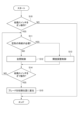
熱システムECU82は、図5に示される処理を所定の周期で繰り返し実行する。なお、熱システムECU82は、図5に示される処理を開始する際に、シャッタ装置8の上側ブレード511及び下側ブレード512のそれぞれの位置を初期位置に設定している。初期位置は、例えば全閉状態に対応する位置である。
Next, the drive control of the
The
図5に示されるように、熱システムECU82は、まず、ステップS10の処理として、始動スイッチ70がオン操作されたか否かを判断する。熱システムECU82は、始動スイッチ70がオン操作されていない場合には、ステップS10の処理で否定的な判断を行って、図5に示される処理を一旦終了する。
As shown in FIG. 5, the
熱システムECU82は、始動スイッチ70がオン操作された場合には、ステップS10の処理で肯定的な判断を行って、続くステップS11の処理として、ラジエータ5及び室外熱交換器6に空気を供給する必要があるか否かを判断する。例えば、熱システムECU82は、以下の(a1)及び(a2)に示される条件が共に満たされることに基づいて、ラジエータ5及び室外熱交換器6に空気を供給する必要がないと判断する。
When the
(a1)A/Cスイッチ710がオン操作されておらず、且つ内気温センサ65により検出される内気温が暖房温度判定値よりも高い場合。すなわち、ヒートポンプ装置30を冷房モード及び暖房モードのいずれでも動作させる必要が無い場合。
(a2)水温センサ64により検出される冷却水の温度が所定の温度判定値以下である場合。すなわち、発熱体22を冷却する必要が無い場合。温度判定値は、発熱体22を冷却すべきか否かを判定することができる値に予め設定されている。
(a1) A case in which the A/
(a2) When the temperature of the cooling water detected by the
なお、(a2)に関しては、例えば発熱体22に含まれるモータ220、インバータ装置221、及びバッテリ222のそれぞれに水温センサ64が設けられている場合、それぞれの冷却水温に対して個別に温度判定値が設定されていてもよい。この場合、モータ220の冷却水温に対する温度判定値は例えば「65[℃]」に設定され、バッテリ222の冷却水温に対する温度判定値は例えば「40[℃]」に設定される。
Regarding (a2), for example, if a
熱システムECU82は、上記の(a1)及び(a2)の条件が共に満たされた場合には、ラジエータ5及び室外熱交換器6に空気を供給する必要がないと判定して、ステップS11の処理で否定的な判断を行う。この場合、熱システムECU82は、ステップS12の処理として、シャッタ装置8の上側開口領域A11,A12及び下側開口領域A13,A14を全閉状態にする全閉制御を実行する。具体的には、熱システムECU82は、上側ブレード511及び下側ブレード512が共に全閉状態になるようにモータ52を駆動させる。これにより、グリル開口部2を通じた空気の導入が遮断されるため、車両Cの空力性能を向上させることができる。よって、車両Cの電費を向上させることができる。
When both of the above conditions (a1) and (a2) are satisfied, the
一方、熱システムECU82は、上記の(a1)及び(a2)の少なくとも一方の条件が満たされていない場合には、ラジエータ5及び室外熱交換器6の少なくとも一方に空気を供給する必要があると判断する。例えば(a1)の条件が満たされていない場合には、A/Cスイッチ710がオン操作されていない場合と、内気温センサ65により検出される内気温が暖房温度判定値以下である場合とが存在する。前者の場合、ヒートポンプ装置30を冷房モードで動作させる必要があるため、室外熱交換器6に空気を供給する必要がある。また、後者の場合、ヒートポンプ装置30を暖房モードで動作させる必要があるため、室外熱交換器6に空気を供給する必要がある。さらに、(a2)の条件が満たされていない場合、すなわち発熱体22の冷却水の温度が所定の温度判定値を超えている場合には、冷却回路20を駆動させて発熱体22を冷却する必要があるため、ラジエータ5に空気を供給する必要がある。
On the other hand, when at least one of the above conditions (a1) and (a2) is not satisfied, the
熱システムECU82は、上記の(a1)及び(a2)の少なくとも一方の条件が満たされておらず、ラジエータ5及び室外熱交換器6の少なくとも一方に空気を供給する必要があると判定した場合には、ステップS11の処理で肯定的な判断を行って、続くステップS13の処理として、シャッタ装置8の上側ブレード511及び下側ブレード512のそれぞれの開度を調整する開度調整制御を実行する。具体的には、熱システムECU82は、上側ブレード511及び下側ブレード512を共に開状態にし、且つ図1に示されるように下側ブレード512の開度よりも上側ブレード511の開度の方が小さくなるようにモータ52を駆動させる。上側ブレード511及び下側ブレード512が共に開状態になることにより、ラジエータ5及び室外熱交換器6に空気を供給することができるため、冷却回路20及びヒートポンプ装置30を駆動させることが可能となる。
When the
図5に示されるように、熱システムECU82は、ステップS12又はステップS13の処理を実行した場合には、ステップS14の処理として、始動スイッチ70がオフ操作されたか否かを判断する。熱システムECU82は、始動スイッチ70がオフ操作されていない場合には、ステップS14の処理で否定的な判断を行って、ステップS11の処理に戻る。一方、熱システムECU82は、ステップS14の処理で肯定的な判断を行った場合には、すなわち始動スイッチ70がオフ操作された場合には、ステップS15の処理として、上側ブレード511及び下側ブレード512を初期位置に変位させた後、図5に示される処理を一旦終了する。
As shown in FIG. 5, when the
以上説明した本実施形態の車両Cによれば、以下の(1)~(5)に示される作用及び効果を得ることができる。
(1)上側ブレード511の開度よりも下側ブレード512の開度の方が小さくなることにより、シャッタ装置8の下側開口領域A13,A14よりも上側開口領域A11,A12の方が、空気が流れ易くなる。そのため、ラジエータ5及び室外熱交換器6のそれぞれの下部5b,6bの空気の圧力を高くなる方向に変化させることができる一方、それらの上部5a,6aの空気の圧力を低くなる方向に変化させることができる。このようにシャッタ装置8の開度の偏りにより空気の圧力を部分的に変化させることで、グリル開口部2の位置に起因する空気の圧力の偏りを軽減することができる。その結果、ラジエータ5及び室外熱交換器6に供給される空気の風量のばらつきを軽減することができるため、それらの熱交換効率を高めることが可能となる。
According to the vehicle C of the present embodiment described above, the following actions and effects (1) to (5) can be obtained.
(1) The opening degree of the
(2)シャッタ装置8は、上側ブレード511及び下側ブレード512を動作させる一つのモータ52を備える。この構成によれば、上側ブレード511を動作させるためのモータと、下側ブレード512を動作させるためのモータとが別々に設けられている構成と比較すると、部品点数を削減することができる。
(2) The
(3)シャッタ装置8は、ラジエータ5に対して空気流れ方向の直前に配置されている。この構成によれば、ラジエータ5の前方に設けられる空間を利用してシャッタ装置8を設置できる。
(4)図1に示されるように、車両Cの上下方向Zにおけるグリル開口部2の幅H11は、車両Cの上下方向Zにおけるシャッタ装置8の下側開口領域A13,A14の幅H12よりも短い。この構成のようにグリル開口部2の幅が短く設定されていれば、導風ダクト4に取り込まれる空気の風量を少なくすることができるため、車両Cの空力性能を向上させることができる。
(3) The
1, the width H11 of the
(5)熱システムECU82は、車両Cの始動スイッチ70がオフ操作されたとき、上側ブレード511及び下側ブレード512を初期位置に変位させる。この構成によれば、始動スイッチ70がオフ操作される都度、上側ブレード511及び下側ブレード512のそれぞれの位置を更正することができる。
(5) When the
(6)熱システムECU82は、ラジエータ5及び室外熱交換器6のそれぞれの動作状態に応じて上側ブレード511及び下側ブレード512のそれぞれの開度を制御する。この構成によれば、ラジエータ5及び室外熱交換器6のそれぞれの動作状態に応じた、より適切な空気の流れを実現することが可能となる。
(6) The
<第2実施形態>
次に、第2実施形態の車両Cについて説明する。以下、第1実施形態の車両Cとの相違点を中心に説明する。
ヒートポンプ装置30の動作状況の一つとして、外気温が低い環境下でヒートポンプ装置30が暖房モードで動作する状況が考えられる。このような状況では、仮にグリル開口部2から進入した水がシャッタ装置8に付着すると、付着した水が凍結することによりシャッタ装置8の各ブレード511,512が開閉動作できなくなる可能性がある。このような場合、各ブレード511,512が開閉動作できなくなることに起因してシャッタ装置8に異常が検出されると、車両Cのインジケータが点灯する等して、運転者が困惑する可能性がある。
Second Embodiment
Next, a vehicle C according to a second embodiment will be described. The following description will focus on the differences from the vehicle C according to the first embodiment.
One of the operating conditions of the
一方、シャッタ装置8では、グリル開口部2の近傍に配置される下側ブレード512は被水し易いのに対し、グリル開口部2から離間して配置される上側ブレード511は被水し難い。これを考慮すれば、付着した水が凍結する可能性のある環境下では、下側ブレード512を閉状態に維持する一方、上側ブレード511のみを開閉動作させれば、仮に下側ブレード512が被水により凍結したとしても、上側開口領域A11,A12を通じて室外熱交換器6に空気を供給することができる。よって、ヒートポンプ装置30を暖房モードで動作させることができる。具体的には、熱システムECU82がシャッタ装置8を以下のように制御する。
On the other hand, in the
本実施形態の熱システムECU82は、ヒートポンプ装置30の動作状態の情報を空調ECU81から取得する。熱システムECU82は、図5に示されるステップS13の処理において、ヒートポンプ装置30が暖房モードで動作しており、且つ外気温センサ61により検出される外気温が凍結判定温度以下であるか否かを判断する。凍結判定温度は、シャッタ装置8に水が付着した際にその水が凍結する可能性のある外気温であるか否かを判定するための温度判定値であり、例えば「5[℃]」に予め設定されている。熱システムECU82は、ヒートポンプ装置30が暖房モードで動作しており、且つ外気温センサ61により検出される外気温が凍結判定温度以下であると判断した場合には、図6に示されるように上側ブレード511が開状態になり、且つ下側ブレード512が閉状態になるようにモータ52を駆動させる。
The
以上説明した本実施形態の車両Cによれば、以下の(7)に示される作用及び効果を更に得ることができる。
(7)本実施形態の車両Cの構成によれば、被水によりシャッタ装置8が凍結し易い環境下であっても、ヒートポンプ装置30を暖房モードで動作させることが可能となる。よって、車室内の暖房を継続することができるため、車室内の快適性を確保することができる。
According to the vehicle C of the present embodiment described above, the following action and effect described in (7) can be further obtained.
(7) According to the configuration of the vehicle C of this embodiment, even in an environment where the
<第3実施形態>
次に、第3実施形態の車両Cについて説明する。以下、第1実施形態の車両Cとの相違点を中心に説明する。
室外熱交換器6は、通常、複数のチューブと、それらのチューブの両端部にそれぞれ連結されるタンクとを有して構成されている。室外熱交換器6では、各チューブの内部を流れる冷媒と、各チューブの外部を流れる空気とで熱交換が行われる。このような構成からなる室外熱交換器6では、チューブの表面に霜が付着すると、空気に対する伝熱面積が実質的に減少することとなるため、熱交換効率が著しく低下するおそれがある。そのため、ヒートポンプ装置30は、室外熱交換器6のチューブの表面に霜が付着した際にその霜を溶かす、いわゆる除霜モードで動作するものがある。除霜モードでは、例えば室外熱交換器6への空気の供給を遮断した状態で室外熱交換器6に冷媒を循環させる。これにより、チューブの表面に付着する霜を冷媒の熱により溶かすことができる。
Third Embodiment
Next, a vehicle C according to a third embodiment will be described. The following description will focus on the differences from the vehicle C according to the first embodiment.
The
一方、除霜モードにおいて室外熱交換器6への空気の供給を遮断するためには、シャッタ装置8の上側ブレード511及び下側ブレード512を共に閉状態にすればよい。しかしながら、それらのブレード511,512を共に閉状態にすると、室外熱交換器6に空気を供給することができないため、ヒートポンプ装置30を暖房モードで動作させることができない。すなわち、車室内の暖房を行うことができないため、車室内の快適性が損なわれる可能性がある。
On the other hand, in order to cut off the supply of air to the
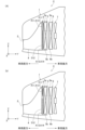
そこで、本実施形態の熱システムECU82は、図5に示されるステップS13の処理において、ヒートポンプ装置30の動作状態の情報を空調ECU81から取得した上で、ヒートポンプ装置30が除霜モードで動作していると判断した場合には、以下の(b1)及び(b2)に示される制御を所定の時間間隔で交互に実行する。
Therefore, in the processing of step S13 shown in FIG. 5, the
(b1)図7(A)に示されるように、上側ブレード511が開状態になり、且つ下側ブレード512が閉状態になるようにモータ52を駆動させる。
(b2)図7(B)に示されるように、上側ブレード511が閉状態になり、且つ下側ブレード512が開状態になるようにモータ52を駆動させる。
(b1) As shown in FIG. 7A, the
(b2) As shown in FIG. 7(B), the
これにより、車両Cでは、(b1)に対応する第1状態と、(b2)に対応する第2状態とが交互に切り替わる。
以上説明した本実施形態の車両Cによれば、以下の(8)に示される作用及び効果を得ることができる。
As a result, in the vehicle C, a first state corresponding to (b1) and a second state corresponding to (b2) are alternately switched.
According to the vehicle C of the present embodiment described above, the following actions and effects described in (8) can be obtained.
(8)上記の(b1)の制御が実行されている場合、室外熱交換器6の上部6aに空気が供給されるため、その部分を吸熱器として用いることができる。また、室外熱交換器6の下部6bには空気が供給されないため、その部分では冷媒の熱により、付着した霜を溶かすことができる。すなわち、上部6aが吸熱エリアとして機能し、下部6bが除霜エリアとして機能する。一方、上記の(b2)の制御が実行されている場合、室外熱交換器6の下部6bに空気が供給されるため、その部分を吸熱器として用いることができる。また、室外熱交換器6の上部6aには空気が供給されないため、その部分では冷媒の熱により、付着した霜を溶かすことができる。すなわち、上部6aが除霜エリアとして機能し、下部6bが吸熱エリアとして機能する。この構成によれば、室外熱交換器6の上部6a及び下部6bに付着する霜を共に除去することができるため、霜の付着に起因する室外熱交換器6の性能の低下を回避することができる。また、室外熱交換器6を吸熱器として継続して利用することができるため、車室内の連続暖房が可能となる。
(8) When the above control (b1) is executed, air is supplied to the
<第4実施形態>
次に、第4実施形態の車両Cについて説明する。以下、第3実施形態の車両Cとの相違点を中心に説明する。
ヒートポンプ装置30が除霜モードで駆動すると、室外熱交換器6の表面には、霜が溶けることにより生成される水が溜まる。この水が凍結すると、室外熱交換器6の熱交換効率が著しく低下したり、室外熱交換器6に凍結割れが生じたりする可能性がある。そのため、室外熱交換器6の表面に溜まる水は可能な限り除去することが望ましい。
Fourth Embodiment
Next, a vehicle C according to a fourth embodiment will be described. The following description will focus on the differences from the vehicle C according to the third embodiment.
When the
そこで、本実施形態の熱システムECU82は、ヒートポンプ装置30が除霜モードで動作した後、室外熱交換器6の表面から水を除去する排水モードを更に実行する。
具体的には、熱システムECU82は、排水モードとして、上記の(b1)及び(b2)に示される制御を所定の時間間隔で交互に実行する。これにより、例えば上記の(b1)の制御から上記の(b2)の制御に切り替わった際には、室外熱交換器6の下部6bは、空気が流れていない状態から、空気が流れる状態に切り替わる。そのため、室外熱交換器6の下部6bを流れる空気の風量を急激に変化させることができる。この空気の風量の急激な変化により、室外熱交換器6の下部6bに溜まっている水が吹き飛ばされる。また、上記の(b2)の制御から上記の(b1)の制御に切り替わった際には、室外熱交換器6の上部6aに溜まっている水が吹き飛ばされる。結果的に、室外熱交換器6に溜まっている水を除去することができる。
Therefore, the
Specifically, the
以上説明した本実施形態の車両Cによれば、以下の(9)に示される作用及び効果を得ることができる。
(9)熱システムECU82は、ヒートポンプ装置30が除霜モードで動作した後、室外熱交換器6の上部6a及び下部6bを通過する空気の風量を急激に変化させる排水モードを実行することにより、室外熱交換器6に溜まっている水を除去する。これにより、除霜モードの実行により室外熱交換器6に溜まる水を除去することができるため、室外熱交換器6の熱交換効率の低下や凍結割れ等を回避することが可能となる。
According to the vehicle C of the present embodiment described above, the following actions and effects described in (9) can be obtained.
(9) After the
<第5実施形態>
次に、第5実施形態の車両Cについて説明する。以下、第1実施形態の車両Cとの相違点を中心に説明する。
図8に示されるように、本実施形態の車両Cでは、ラジエータ5と室外熱交換器6とがアウターフィン9を介して熱的に連結されている。すなわち、アウターフィン9を介してラジエータ5と室外熱交換器6との間で熱交換が可能となっている。これにより、例えば室外熱交換器6が吸熱器として動作している場合、ラジエータ5の廃熱を、アウターフィン9を介して室外熱交換器6に伝達させることができるため、車両C全体としての熱効率を高めることができる。結果的に、車両Cの電費を向上させることが可能となる。
Fifth Embodiment
Next, a vehicle C according to the fifth embodiment will be described. The following description will focus on the differences from the vehicle C according to the first embodiment.
As shown in Fig. 8, in the vehicle C of this embodiment, the
一方、ラジエータ5の廃熱を室外熱交換器6に伝達させる際には、シャッタ装置8の上側ブレード511及び下側ブレード512を共に閉状態にすることが有効である。これにより、ラジエータ5が空気により冷却されなくなるため、ラジエータ5の廃熱を効率良く室外熱交換器6に伝達させることが可能となる。しかしながら、このようにラジエータ5の廃熱を室外熱交換器6に伝達させるだけでは、空調装置40の暖房要求を満たすことができない可能性がある。
On the other hand, when transferring the waste heat of the
具体的には、図9に示されるように、ラジエータ5が、その下部5bから上部5aに向かって冷却水がU字状に流れるように構成されているとする。この場合、ラジエータ5の熱がアウターフィン9を介して室外熱交換器6に伝達される結果、ラジエータ5の内部を流れる冷却水の温度は下流に向かうほど低下する。すなわち、ラジエータ5の下部5bの温度よりも、その上部5aの温度の方が低くなる。そのため、室外熱交換器6は、ラジエータ5の下部5bからは必要な熱量を吸収することができる一方で、ラジエータ5の上部5aからは必要な熱量を吸収できない可能性がある。これにより室外熱交換器6の全体としての吸熱量が不足すると、車室内に送風される空気を空調装置40により十分に加熱することができなくなるため、車室内の暖房が適切に行われ難くなり、車室内の快適性が損なわれるおそれがある。
Specifically, as shown in FIG. 9, the
そこで、本実施形態の熱システムECU82は、アウターフィン9を介してラジエータ5の熱を室外熱交換器6に伝達するだけでは室外熱交換器6の吸熱量が不足する場合、図8に示されるように、上側ブレード511が開状態になり、且つ下側ブレード512が閉状態になるようにモータ52を駆動させる。これにより、室外熱交換器6では、その下部6bにおいてアウターフィン9を介してラジエータ5の廃熱を吸収することができる一方、その上部6aにおいて不足分の熱量を空気から吸熱することができる。結果的に、室外熱交換器6の全体として必要な吸熱量を確保することができる。
In this embodiment, when the amount of heat absorption by the
以上説明した本実施形態の車両Cによれば、以下の(10)に示される作用及び効果を得ることができる。
(10)室外熱交換器6がアウターフィン9を介してラジエータ5の熱を冷媒に吸収させる吸熱器として動作しているとき、熱システムECU82は、上側ブレード511を開状態に設定する一方、下側ブレード512を閉状態に設定する。この構成によれば、より的確に室外熱交換器6の吸熱量を確保することができるため、車室内の暖房が適切に行われるようになる。よって、車室内の快適性を確保することができる。
According to the vehicle C of the present embodiment described above, the following actions and effects described in (10) can be obtained.
(10) When the
<第6実施形態>
次に、第6実施形態の車両Cについて説明する。以下、第1実施形態の車両Cとの相違点を中心に説明する。
図10に示されるように、本実施形態の車両Cには、ラジエータ5に代えて多機能熱交換器10が搭載されるとともに、室外熱交換器6に代えてラジエータ11が搭載されている。
Sixth Embodiment
Next, a vehicle C according to the sixth embodiment will be described. The following description will focus on the differences from the vehicle C according to the first embodiment.
As shown in FIG. 10, a vehicle C of this embodiment is equipped with a
多機能熱交換器10は、その下部に第1熱交換部10Aを有し、その上部に第2熱交換部10Bを有している。第1熱交換部10Aは、上述したヒートポンプ装置30の室外熱交換器6として用いられる。第1熱交換部10Aは、シャッタ装置8の下側開口領域A13,A14に対向して配置されている。第2熱交換部10Bの内部には、バッテリ222を冷却するための冷却水が流れている。第2熱交換部10Bは、その内部を流れる冷却水と、その外部を流れる空気とを熱交換させることにより冷却水を冷却する。第2熱交換部10Bは、シャッタ装置8の上側開口領域A11,A12に対向して配置されている。
The
ラジエータ11の内部には、モータ220を冷却するための冷却水が流れている。ラジエータ11は、その内部を流れる冷却水と、その外部を流れる空気とを熱交換させることにより冷却水を冷却する。ラジエータ11の上部11aはシャッタ装置8の上側開口領域A11,A12に対向するように配置されている。ラジエータ11の下部11bは下側開口領域A13,A14に対向するように配置されている。
Cooling water flows inside the
このように、本実施形態の車両Cでは、モータ220を冷却するための冷却回路と、バッテリ222を冷却するための冷却回路とが独立して設けられている。ラジエータ11では、第2熱交換部10Bよりも高温の冷却水を冷却することが可能となっている。本実施形態では、モータ220が第1発熱体に相当し、バッテリ222が第2発熱体に相当する。
In this manner, in the vehicle C of this embodiment, a cooling circuit for cooling the
熱システムECU82は、バッテリ222の冷却が要求されていない場合、図10に示されるように、上側ブレード511が閉状態になり、且つ下側ブレード512が開状態になるようにモータ52を駆動させる。これにより、グリル開口部2から導入される空気が多機能熱交換器10の第1熱交換部10Aのみに流れるようになるため、第1熱交換部10A及び第2熱交換部10Bの両方に空気が流れている場合と比較すると、第1熱交換部10Aを流れる空気の風量を増加させることができる。
When cooling of the
なお、熱システムECU82は、ヒートポンプ装置30が停止している場合、上側ブレード511が開状態になり、且つ下側ブレード512が閉状態になるようにモータ52を駆動させてもよい。
以上説明した本実施形態の車両Cによれば、以下の(11)に示される作用及び効果を得ることができる。
In addition, when the
According to the vehicle C of the present embodiment described above, the following actions and effects described in (11) can be obtained.
(11)熱システムECU82は、バッテリ222の冷却が要求されていない場合、下側ブレード512を開状態に設定する一方、上側ブレード511を閉状態に設定する。この構成によれば、空気との熱交換が不要な多機能熱交換器10の第1熱交換部10Aには空気が供給されなくなるとともに、その分だけ多機能熱交換器10の第2熱交換部10Bに供給される空気の風量を増加させることができる。よって、例えば第1熱交換部10Aがヒートポンプ装置30においてコンデンサとして用いられている場合には、第1熱交換部10Aを流れる冷媒をより的確に冷却することができるため、冷媒の冷却効率を高めることができる。したがって、第1熱交換部10Aを小型化すること等が可能となる。
(11) When cooling of the
<他の実施形態>
なお、上記実施形態は、以下の形態にて実施することもできる。
・第3実施形態の車両Cには、第5実施形態の車両Cの構成、すなわちラジエータ5と室外熱交換器6とがアウターフィン9を介して熱的に連結されている構成を適用してもよい。この構成によれば、ヒートポンプ装置30は、室外熱交換器6の表面に付着する霜を除去する除霜モードを実行する際に、室外熱交換器6の内部を循環する冷媒の熱を利用するという方法に代えて、ラジエータ5からアウターフィン9を介して室外熱交換器6に伝達される熱を利用するという方法を用いることが可能となる。
<Other embodiments>
The above embodiment can also be implemented in the following manner.
The configuration of the vehicle C of the fifth embodiment, that is, the configuration in which the
・シャッタ装置8は、上側ブレード511及び下側ブレード512といった2つの開閉部を有するものに限らず、3つ以上の開閉部を有するものであってもよい。
・シャッタ装置8は、ラジエータ5と室外熱交換器6との間、あるいは室外熱交換器6に対して空気流れ方向の直後に配置されていてもよい。
The
The
・第1~第5実施形態の車両Cは、ラジエータ5及び室外熱交換器6に供給される空気の風量を変化させる開閉装置として、ラジエータ5の前方に配置されるシャッタ装置8を用いるものであった。これに代えて、シャッタ装置8と同一又は類似の機能を有するシャッタ機構を送風機7のファンシュラウドに設けてもよい。この場合、送風機7に設けられるシャッタ機構が開閉装置に相当する。第6実施形態の車両Cに関しても同様である。
- The vehicle C of the first to fifth embodiments uses a
・車両Cには、導風ダクト4が設けられていなくてもよい。
・本開示に記載の熱システムECU82及びその制御方法は、コンピュータプログラムにより具体化された1つ又は複数の機能を実行するようにプログラムされたプロセッサ及びメモリを構成することによって提供された1つ又は複数の専用コンピュータにより、実現されてもよい。本開示に記載の熱システムECU82及びその制御方法は、1つ又は複数の専用ハードウェア論理回路を含むプロセッサを構成することによって提供された専用コンピュータにより、実現されてもよい。本開示に記載の熱システムECU82及びその制御方法は、1つ又は複数の機能を実行するようにプログラムされたプロセッサ及びメモリと1つ又は複数のハードウェア論理回路を含むプロセッサとの組み合わせにより構成された1つ又は複数の専用コンピュータにより、実現されてもよい。コンピュータプログラムは、コンピュータにより実行されるインストラクションとして、コンピュータ読み取り可能な非遷移有形記録媒体に記憶されていてもよい。専用ハードウェア論理回路及びハードウェア論理回路は、複数の論理回路を含むデジタル回路、又はアナログ回路により実現されてもよい。
The vehicle C does not need to be provided with the
The
・各実施形態の構成は電動車両に限らず、ハイブリッド車両やプラグインハイブリッド車両にも適用可能である。例えば第2~第4実施形態、及び第6実施形態の構成はハイブリッド車両に適用可能である。また、第1~第4実施形態、及び第6実施形態の構成はプラグインハイブリッド車両に適用可能である。 - The configurations of each embodiment are not limited to electric vehicles, but can also be applied to hybrid vehicles and plug-in hybrid vehicles. For example, the configurations of the second to fourth embodiments and the sixth embodiment can be applied to hybrid vehicles. Furthermore, the configurations of the first to fourth embodiments and the sixth embodiment can be applied to plug-in hybrid vehicles.
・本開示は上記の具体例に限定されるものではない。上記の具体例に、当業者が適宜設計変更を加えたものも、本開示の特徴を備えている限り、本開示の範囲に包含される。前述した各具体例が備える各要素、及びその配置、条件、形状等は、例示したものに限定されるわけではなく適宜変更することができる。前述した各具体例が備える各要素は、技術的な矛盾が生じない限り、適宜組み合わせを変えることができる。 - This disclosure is not limited to the specific examples above. Design modifications to the specific examples above made by a person skilled in the art are also included within the scope of this disclosure as long as they have the features of this disclosure. The elements of each of the specific examples described above, as well as their arrangement, conditions, shapes, etc., are not limited to those exemplified and can be modified as appropriate. The elements of each of the specific examples described above can be combined in different ways as appropriate, as long as no technical contradictions arise.
A11,A12:上側開口領域(第2部位)
A13,A14:下側開口領域(第1部位)
C:車両
2:グリル開口部
5,11:ラジエータ(熱交換器)
6:室外熱交換器
8:シャッタ装置(開閉装置)
10:多機能熱交換器
10A:第1熱交換部
10B:第2熱交換部
30:ヒートポンプ装置
51:ブレード(開閉部)
52:モータ
82:熱システムECU(制御部)
511:上側ブレード(第2開閉部)
512:下側ブレード(第1開閉部)
A11, A12: Upper opening region (second region)
A13, A14: Lower opening region (first portion)
C: Vehicle 2: Grill opening 5, 11: Radiator (heat exchanger)
6: Outdoor heat exchanger 8: Shutter device (opening/closing device)
10:
52: Motor 82: Thermal system ECU (control unit)
511: Upper blade (second opening/closing part)
512: Lower blade (first opening/closing part)
Claims (6)
開閉部(51)の開閉動作により前記熱交換器に供給される空気の風量を変化させることが可能な開閉装置(8)と、
前記開閉装置を制御する制御部(82)と、を備え、
前記グリル開口部の開口面積は、前記熱交換器の前面投影面積よりも小さく、
前記開閉装置は、前記開閉部として、同開閉装置の第1部位(A13,A14)を開閉する第1開閉部(512)と、同開閉装置において前記第1部位よりも前記グリル開口部から遠い第2部位(A11,A12)を開閉する第2開閉部(511)と、を有し、
前記熱交換器として、
車両の第1発熱体を冷却する冷却水と空気とで熱交換を行うラジエータ(11)と、
ヒートポンプ装置(30)を循環する冷媒と空気とで熱交換を行う第1熱交換部(10A)、及び前記第1発熱体とは別の第2発熱体を冷却する冷却水と空気とで熱交換を行う第2熱交換部(10B)を有する室外熱交換器(10)と、を有し、
前記室外熱交換器において前記第1熱交換部が前記開閉装置の前記第1部位に対向して配置されるとともに、前記第2熱交換部が前記開閉装置の前記第2部位に対向して配置されており、
前記制御部は、
前記第2部位の開度よりも前記第1部位の開度の方が小さくなるように前記第1開閉部及び前記第2開閉部を動作させ、
前記第2発熱体の冷却が要求されていない場合、前記第1開閉部を開状態に設定する一方、前記第2開閉部を閉状態に設定する
車両。 a heat exchanger (5, 6, 10, 11) for exchanging heat with air introduced through a grill opening (2);
an opening/closing device (8) capable of changing the volume of air supplied to the heat exchanger by opening and closing an opening/closing part (51);
A control unit (82) that controls the opening and closing device,
The opening area of the grill opening is smaller than the frontal projection area of the heat exchanger,
The opening/closing device has, as the opening/closing part, a first opening/closing part (512) that opens and closes a first portion (A13, A14) of the opening/closing device, and a second opening/closing part (511) that opens and closes a second portion (A11, A12) of the opening/closing device that is farther from the grill opening than the first portion,
The heat exchanger includes:
a radiator (11) for performing heat exchange between air and a cooling water for cooling a first heating element of a vehicle;
an outdoor heat exchanger (10) having a first heat exchange section (10A) that performs heat exchange between a refrigerant circulating in a heat pump device (30) and air, and a second heat exchange section (10B) that performs heat exchange between a cooling water that cools a second heating element different from the first heating element and air,
In the outdoor heat exchanger, the first heat exchange unit is disposed opposite the first portion of the opening/closing device, and the second heat exchange unit is disposed opposite the second portion of the opening/closing device,
The control unit is
operating the first opening/closing unit and the second opening/closing unit so that the opening degree of the first portion is smaller than the opening degree of the second portion;
When cooling of the second heating element is not required, the first opening/closing unit is set to an open state, and the second opening/closing unit is set to a closed state.
開閉部(51)の開閉動作により前記熱交換器に供給される空気の風量を変化させることが可能な開閉装置(8)と、
前記開閉装置を制御する制御部(82)と、を備え、
前記グリル開口部の開口面積は、前記熱交換器の前面投影面積よりも小さく、
前記開閉装置は、前記開閉部として、同開閉装置の第1部位(A13,A14)を開閉する第1開閉部(512)と、同開閉装置において前記第1部位よりも前記グリル開口部から遠い第2部位(A11,A12)を開閉する第2開閉部(511)と、を有し、
前記熱交換器として、ヒートポンプ装置(30)を循環する冷媒と空気とで熱交換を行う室外熱交換器(6)を有し、
前記制御部は、
前記第2部位の開度よりも前記第1部位の開度の方が小さくなるように前記第1開閉部及び前記第2開閉部を動作させ、
前記ヒートポンプ装置において前記室外熱交換器が空気の熱を冷媒に吸収させる吸熱器として動作しているとき、前記第1開閉部が閉状態に設定されており、且つ前記第2開閉部が開状態に設定されている第1状態と、前記第1開閉部が開状態に設定されており、且つ前記第2開閉部が閉状態に設定されている第2状態とを交互に切り替える
車両。 a heat exchanger (5, 6, 10, 11) for exchanging heat with air introduced through a grill opening (2);
an opening/closing device (8) capable of changing the volume of air supplied to the heat exchanger by opening and closing an opening/closing part (51);
A control unit (82) that controls the opening and closing device,
The opening area of the grill opening is smaller than the frontal projection area of the heat exchanger,
The opening/closing device has, as the opening/closing part, a first opening/closing part (512) that opens and closes a first portion (A13, A14) of the opening/closing device, and a second opening/closing part (511) that opens and closes a second portion (A11, A12) of the opening/closing device that is farther from the grill opening than the first portion,
The heat exchanger includes an outdoor heat exchanger (6) that exchanges heat between a refrigerant circulating in the heat pump device (30) and air,
The control unit is
operating the first opening/closing unit and the second opening/closing unit so that the opening degree of the first portion is smaller than the opening degree of the second portion;
When the outdoor heat exchanger in the heat pump device operates as a heat sink that absorbs heat of air into a refrigerant, the vehicle alternates between a first state in which the first opening/closing unit is set to a closed state and the second opening/closing unit is set to an open state, and a second state in which the first opening/closing unit is set to an open state and the second opening/closing unit is set to a closed state.
請求項1又は2に記載の車両。 The vehicle according to claim 1 or 2, wherein the opening and closing device is disposed immediately before or immediately after the heat exchanger in an air flow direction.
請求項1~3のいずれか一項に記載の車両。 The vehicle according to any one of claims 1 to 3, wherein a width of the grill opening in a vertical direction of the vehicle is shorter than a width of the first portion in the vertical direction of the vehicle.
請求項1~4のいずれか一項に記載の車両。 The vehicle according to any one of claims 1 to 4, wherein the control unit displaces the first opening/closing unit and the second opening/closing unit to initial positions when a starter switch of the vehicle is turned off.
請求項1~5のいずれか一項に記載の車両。
The vehicle according to any one of claims 1 to 5, wherein the opening/closing device further includes a motor (52) that operates the first opening/closing unit and the second opening/closing unit.
Priority Applications (3)
| Application Number | Priority Date | Filing Date | Title |
|---|---|---|---|
| JP2020153320A JP7501260B2 (en) | 2020-09-11 | 2020-09-11 | vehicle |
| CN202180061903.9A CN116056924A (en) | 2020-09-11 | 2021-08-17 | Vehicle with a vehicle body having a vehicle body support |
| PCT/JP2021/030001 WO2022054504A1 (en) | 2020-09-11 | 2021-08-17 | Vehicle |
Applications Claiming Priority (1)
| Application Number | Priority Date | Filing Date | Title |
|---|---|---|---|
| JP2020153320A JP7501260B2 (en) | 2020-09-11 | 2020-09-11 | vehicle |
Publications (3)
| Publication Number | Publication Date |
|---|---|
| JP2022047416A JP2022047416A (en) | 2022-03-24 |
| JP2022047416A5 JP2022047416A5 (en) | 2022-12-13 |
| JP7501260B2 true JP7501260B2 (en) | 2024-06-18 |
Family
ID=80631519
Family Applications (1)
| Application Number | Title | Priority Date | Filing Date |
|---|---|---|---|
| JP2020153320A Active JP7501260B2 (en) | 2020-09-11 | 2020-09-11 | vehicle |
Country Status (3)
| Country | Link |
|---|---|
| JP (1) | JP7501260B2 (en) |
| CN (1) | CN116056924A (en) |
| WO (1) | WO2022054504A1 (en) |
Citations (10)
| Publication number | Priority date | Publication date | Assignee | Title |
|---|---|---|---|---|
| JP2000320331A (en) | 1999-03-11 | 2000-11-21 | Denso Corp | Cooling device for vehicle |
| US20110246023A1 (en) | 2010-04-01 | 2011-10-06 | Gm Global Technoloy Operations, Inc. | Powertrain Thermal Control with Grille Airflow Shutters |
| US20140246863A1 (en) | 2013-03-04 | 2014-09-04 | General Electric Company | System for cooling power generation system |
| JP2014223867A (en) | 2013-05-16 | 2014-12-04 | カルソニックカンセイ株式会社 | Vehicle air conditioner and vehicle air conditioner control method |
| KR101575255B1 (en) | 2014-05-27 | 2015-12-07 | 현대자동차 주식회사 | Active air flap of vehicle |
| JP2016190533A (en) | 2015-03-31 | 2016-11-10 | カルソニックカンセイ株式会社 | Cooling system |
| JP2019038275A (en) | 2017-08-22 | 2019-03-14 | マツダ株式会社 | Thermal insulation structure of engine |
| JP2019051900A (en) | 2017-09-19 | 2019-04-04 | 株式会社デンソー | Heat exchange system |
| JP2019214288A (en) | 2018-06-12 | 2019-12-19 | 株式会社デンソー | Shutter apparatus |
| WO2020121923A1 (en) | 2018-12-14 | 2020-06-18 | 株式会社デンソー | Vehicle heat exchange system |
-
2020
- 2020-09-11 JP JP2020153320A patent/JP7501260B2/en active Active
-
2021
- 2021-08-17 WO PCT/JP2021/030001 patent/WO2022054504A1/en active Application Filing
- 2021-08-17 CN CN202180061903.9A patent/CN116056924A/en active Pending
Patent Citations (10)
| Publication number | Priority date | Publication date | Assignee | Title |
|---|---|---|---|---|
| JP2000320331A (en) | 1999-03-11 | 2000-11-21 | Denso Corp | Cooling device for vehicle |
| US20110246023A1 (en) | 2010-04-01 | 2011-10-06 | Gm Global Technoloy Operations, Inc. | Powertrain Thermal Control with Grille Airflow Shutters |
| US20140246863A1 (en) | 2013-03-04 | 2014-09-04 | General Electric Company | System for cooling power generation system |
| JP2014223867A (en) | 2013-05-16 | 2014-12-04 | カルソニックカンセイ株式会社 | Vehicle air conditioner and vehicle air conditioner control method |
| KR101575255B1 (en) | 2014-05-27 | 2015-12-07 | 현대자동차 주식회사 | Active air flap of vehicle |
| JP2016190533A (en) | 2015-03-31 | 2016-11-10 | カルソニックカンセイ株式会社 | Cooling system |
| JP2019038275A (en) | 2017-08-22 | 2019-03-14 | マツダ株式会社 | Thermal insulation structure of engine |
| JP2019051900A (en) | 2017-09-19 | 2019-04-04 | 株式会社デンソー | Heat exchange system |
| JP2019214288A (en) | 2018-06-12 | 2019-12-19 | 株式会社デンソー | Shutter apparatus |
| WO2020121923A1 (en) | 2018-12-14 | 2020-06-18 | 株式会社デンソー | Vehicle heat exchange system |
Also Published As
| Publication number | Publication date |
|---|---|
| JP2022047416A (en) | 2022-03-24 |
| CN116056924A (en) | 2023-05-02 |
| WO2022054504A1 (en) | 2022-03-17 |
Similar Documents
| Publication | Publication Date | Title |
|---|---|---|
| US10913332B2 (en) | Heat exchange unit | |
| JP7232638B2 (en) | Temperature control system for electric vehicles | |
| JP4923859B2 (en) | Vehicle air conditioner and program | |
| JP3722041B2 (en) | Air conditioner for vehicles | |
| US10875384B2 (en) | Air flow circulation structure for vehicle | |
| CN107614301B (en) | Air conditioner for vehicle | |
| JP2002352867A (en) | Battery temperature controller for electric vehicle | |
| JP2002354608A (en) | Battery cooling device for electric automobile | |
| WO2020044785A1 (en) | Vehicle air conditioner | |
| JP6939575B2 (en) | Vehicle cooling system | |
| JP6721007B2 (en) | Cooling system | |
| JP2008185021A (en) | Vehicle cooling system | |
| JP2019189083A (en) | Cooling device | |
| JP7501260B2 (en) | vehicle | |
| JP4389608B2 (en) | Vehicle control device | |
| JP2006341841A (en) | Seat air conditioning unit | |
| JP6849502B2 (en) | Vehicle cooling system | |
| JP2017165141A (en) | Air conditioner for vehicle | |
| JP2024073319A (en) | Vehicle air conditioning system | |
| JP2000211350A (en) | Vehicle air-conditioner | |
| KR102656590B1 (en) | Air conditioning system for automotive vehicles | |
| JP2006341840A (en) | Seat air conditioning unit | |
| WO2022270594A1 (en) | Vehicular air conditioning device | |
| JP2007126046A (en) | Heating device | |
| JP2018184110A (en) | Vehicle thermal management device |
Legal Events
| Date | Code | Title | Description |
|---|---|---|---|
| A521 | Request for written amendment filed |
Free format text: JAPANESE INTERMEDIATE CODE: A523 Effective date: 20221205 |
|
| A621 | Written request for application examination |
Free format text: JAPANESE INTERMEDIATE CODE: A621 Effective date: 20230802 |
|
| A131 | Notification of reasons for refusal |
Free format text: JAPANESE INTERMEDIATE CODE: A131 Effective date: 20240305 |
|
| A521 | Request for written amendment filed |
Free format text: JAPANESE INTERMEDIATE CODE: A523 Effective date: 20240404 |
|
| TRDD | Decision of grant or rejection written | ||
| A01 | Written decision to grant a patent or to grant a registration (utility model) |
Free format text: JAPANESE INTERMEDIATE CODE: A01 Effective date: 20240507 |
|
| A61 | First payment of annual fees (during grant procedure) |
Free format text: JAPANESE INTERMEDIATE CODE: A61 Effective date: 20240520 |
|
| R150 | Certificate of patent or registration of utility model |
Ref document number: 7501260 Country of ref document: JP Free format text: JAPANESE INTERMEDIATE CODE: R150 |