JP7488332B2 - Method for manufacturing rotary tools and machined products - Google Patents
Method for manufacturing rotary tools and machined products Download PDFInfo
- Publication number
- JP7488332B2 JP7488332B2 JP2022510595A JP2022510595A JP7488332B2 JP 7488332 B2 JP7488332 B2 JP 7488332B2 JP 2022510595 A JP2022510595 A JP 2022510595A JP 2022510595 A JP2022510595 A JP 2022510595A JP 7488332 B2 JP7488332 B2 JP 7488332B2
- Authority
- JP
- Japan
- Prior art keywords
- tip
- cutting edge
- rotary tool
- insert
- workpiece
- Prior art date
- Legal status (The legal status is an assumption and is not a legal conclusion. Google has not performed a legal analysis and makes no representation as to the accuracy of the status listed.)
- Active
Links
- 238000004519 manufacturing process Methods 0.000 title description 19
- 238000000034 method Methods 0.000 title description 8
- 238000005520 cutting process Methods 0.000 claims description 103
- 238000013459 approach Methods 0.000 claims description 3
- 239000000463 material Substances 0.000 description 5
- 230000002093 peripheral effect Effects 0.000 description 5
- MTPVUVINMAGMJL-UHFFFAOYSA-N trimethyl(1,1,2,2,2-pentafluoroethyl)silane Chemical compound C[Si](C)(C)C(F)(F)C(F)(F)F MTPVUVINMAGMJL-UHFFFAOYSA-N 0.000 description 5
- 239000011195 cermet Substances 0.000 description 3
- 238000010586 diagram Methods 0.000 description 3
- 229910052751 metal Inorganic materials 0.000 description 3
- 239000002184 metal Substances 0.000 description 3
- 239000000203 mixture Substances 0.000 description 3
- 229910001018 Cast iron Inorganic materials 0.000 description 2
- 229910000831 Steel Inorganic materials 0.000 description 2
- NRTOMJZYCJJWKI-UHFFFAOYSA-N Titanium nitride Chemical compound [Ti]#N NRTOMJZYCJJWKI-UHFFFAOYSA-N 0.000 description 2
- PNEYBMLMFCGWSK-UHFFFAOYSA-N aluminium oxide Inorganic materials [O-2].[O-2].[O-2].[Al+3].[Al+3] PNEYBMLMFCGWSK-UHFFFAOYSA-N 0.000 description 2
- 238000005229 chemical vapour deposition Methods 0.000 description 2
- 239000011248 coating agent Substances 0.000 description 2
- 238000000576 coating method Methods 0.000 description 2
- 230000014509 gene expression Effects 0.000 description 2
- 230000005484 gravity Effects 0.000 description 2
- 238000003754 machining Methods 0.000 description 2
- 238000003801 milling Methods 0.000 description 2
- 238000005240 physical vapour deposition Methods 0.000 description 2
- 239000010959 steel Substances 0.000 description 2
- 229910000851 Alloy steel Inorganic materials 0.000 description 1
- 229910000975 Carbon steel Inorganic materials 0.000 description 1
- RTAQQCXQSZGOHL-UHFFFAOYSA-N Titanium Chemical compound [Ti] RTAQQCXQSZGOHL-UHFFFAOYSA-N 0.000 description 1
- 229910009043 WC-Co Inorganic materials 0.000 description 1
- 239000011230 binding agent Substances 0.000 description 1
- 239000010962 carbon steel Substances 0.000 description 1
- 239000000919 ceramic Substances 0.000 description 1
- 239000002131 composite material Substances 0.000 description 1
- 229910052593 corundum Inorganic materials 0.000 description 1
- -1 ferrous metals Chemical class 0.000 description 1
- 239000002245 particle Substances 0.000 description 1
- 239000010935 stainless steel Substances 0.000 description 1
- 229910001220 stainless steel Inorganic materials 0.000 description 1
- 239000010936 titanium Substances 0.000 description 1
- 229910052719 titanium Inorganic materials 0.000 description 1
- 150000003609 titanium compounds Chemical group 0.000 description 1
- 229910001845 yogo sapphire Inorganic materials 0.000 description 1
Images


Classifications
-
- B—PERFORMING OPERATIONS; TRANSPORTING
- B23—MACHINE TOOLS; METAL-WORKING NOT OTHERWISE PROVIDED FOR
- B23C—MILLING
- B23C5/00—Milling-cutters
- B23C5/02—Milling-cutters characterised by the shape of the cutter
- B23C5/10—Shank-type cutters, i.e. with an integral shaft
- B23C5/1009—Ball nose end mills
- B23C5/1027—Ball nose end mills with one or more removable cutting inserts
-
- B—PERFORMING OPERATIONS; TRANSPORTING
- B23—MACHINE TOOLS; METAL-WORKING NOT OTHERWISE PROVIDED FOR
- B23C—MILLING
- B23C5/00—Milling-cutters
- B23C5/02—Milling-cutters characterised by the shape of the cutter
- B23C5/10—Shank-type cutters, i.e. with an integral shaft
- B23C5/109—Shank-type cutters, i.e. with an integral shaft with removable cutting inserts
-
- B—PERFORMING OPERATIONS; TRANSPORTING
- B23—MACHINE TOOLS; METAL-WORKING NOT OTHERWISE PROVIDED FOR
- B23C—MILLING
- B23C5/00—Milling-cutters
- B23C5/16—Milling-cutters characterised by physical features other than shape
- B23C5/20—Milling-cutters characterised by physical features other than shape with removable cutter bits or teeth or cutting inserts
- B23C5/202—Plate-like cutting inserts with special form
-
- B—PERFORMING OPERATIONS; TRANSPORTING
- B23—MACHINE TOOLS; METAL-WORKING NOT OTHERWISE PROVIDED FOR
- B23C—MILLING
- B23C5/00—Milling-cutters
- B23C5/16—Milling-cutters characterised by physical features other than shape
- B23C5/20—Milling-cutters characterised by physical features other than shape with removable cutter bits or teeth or cutting inserts
- B23C5/22—Securing arrangements for bits or teeth or cutting inserts
- B23C5/2204—Securing arrangements for bits or teeth or cutting inserts with cutting inserts clamped against the walls of the recess in the cutter body by a clamping member acting upon the wall of a hole in the insert
- B23C5/2208—Securing arrangements for bits or teeth or cutting inserts with cutting inserts clamped against the walls of the recess in the cutter body by a clamping member acting upon the wall of a hole in the insert for plate-like cutting inserts
-
- B—PERFORMING OPERATIONS; TRANSPORTING
- B23—MACHINE TOOLS; METAL-WORKING NOT OTHERWISE PROVIDED FOR
- B23C—MILLING
- B23C5/00—Milling-cutters
- B23C5/16—Milling-cutters characterised by physical features other than shape
- B23C5/20—Milling-cutters characterised by physical features other than shape with removable cutter bits or teeth or cutting inserts
- B23C5/22—Securing arrangements for bits or teeth or cutting inserts
- B23C5/2239—Securing arrangements for bits or teeth or cutting inserts with cutting inserts clamped by a clamping member acting almost perpendicular on the cutting face
- B23C5/2243—Securing arrangements for bits or teeth or cutting inserts with cutting inserts clamped by a clamping member acting almost perpendicular on the cutting face for plate-like cutting inserts
-
- B—PERFORMING OPERATIONS; TRANSPORTING
- B23—MACHINE TOOLS; METAL-WORKING NOT OTHERWISE PROVIDED FOR
- B23C—MILLING
- B23C2200/00—Details of milling cutting inserts
- B23C2200/04—Overall shape
- B23C2200/0405—Hexagonal
- B23C2200/0411—Hexagonal irregular
-
- B—PERFORMING OPERATIONS; TRANSPORTING
- B23—MACHINE TOOLS; METAL-WORKING NOT OTHERWISE PROVIDED FOR
- B23C—MILLING
- B23C2200/00—Details of milling cutting inserts
- B23C2200/08—Rake or top surfaces
- B23C2200/083—Rake or top surfaces curved
-
- B—PERFORMING OPERATIONS; TRANSPORTING
- B23—MACHINE TOOLS; METAL-WORKING NOT OTHERWISE PROVIDED FOR
- B23C—MILLING
- B23C2200/00—Details of milling cutting inserts
- B23C2200/20—Top or side views of the cutting edge
- B23C2200/203—Curved cutting edges
-
- B—PERFORMING OPERATIONS; TRANSPORTING
- B23—MACHINE TOOLS; METAL-WORKING NOT OTHERWISE PROVIDED FOR
- B23C—MILLING
- B23C2200/00—Details of milling cutting inserts
- B23C2200/36—Other features of the milling insert not covered by B23C2200/04 - B23C2200/32
- B23C2200/369—Double-sided inserts
-
- B—PERFORMING OPERATIONS; TRANSPORTING
- B23—MACHINE TOOLS; METAL-WORKING NOT OTHERWISE PROVIDED FOR
- B23C—MILLING
- B23C2210/00—Details of milling cutters
- B23C2210/20—Number of cutting edges
- B23C2210/202—Number of cutting edges three
Landscapes
- Engineering & Computer Science (AREA)
- Mechanical Engineering (AREA)
- Cutting Tools, Boring Holders, And Turrets (AREA)
- Milling Processes (AREA)
Description
本出願は、2020年3月25日に出願された日本国特許出願2020-054294号の優先権を主張するものであり、この先の出願の開示全体を、ここに参照のために取り込む。 This application claims priority to Japanese Patent Application No. 2020-054294, filed on March 25, 2020, the entire disclosure of which is incorporated herein by reference.
本開示は、一般的には、被削材の切削加工に用いられる回転工具及び切削加工物の製造方法に関する。より具体的には、フライス加工などに用いられる転削工具に関する。This disclosure generally relates to a rotary tool used in cutting a workpiece and a method for manufacturing a cut product. More specifically, this disclosure relates to a cutting tool used in milling and the like.
金属などの被削材を切削加工する際に用いられる回転工具(切削工具)として、例えば国際公開第2010/114094号(特許文献1)、国際公開第2015/174200号(特許文献2)及び特表2010-523352号公報(特許文献3)に記載の切削工具が知られている。特許文献3に記載の切削工具は、切削インサートを有する。この切削インサートは、2つの端面(上面及び下面)と、周囲面と、端面及び周囲面の交わりに形成された切削刃(上切削刃及び下切削刃)と、を有する。切削刃は、回転軸線の先端に向かって突出した凸形状であるとともに、この凸形状の端部を基準として、外側に位置する主切削刃と、内側に位置する副切削刃と、を有する。周囲面は、上切削刃における端部及び下切削刃における端部を接続する領域を有する。この領域は、2つの端部を直線的に接続している。そのため、切削インサートを上面視した場合に、2つの端部を結ぶ外周縁が直線状である。As a rotary tool (cutting tool) used in cutting a workpiece such as metal, for example, the cutting tools described in International Publication No. 2010/114094 (Patent Document 1), International Publication No. 2015/174200 (Patent Document 2), and JP-A-2010-523352 (Patent Document 3) are known. The cutting tool described in
引用文献3に記載の切削工具を用いて切削加工を行う場合、周囲面における上記の領域が被削材に接触することを避けるためには、アキシャルレーキを大きな負の値にする必要がある。すなわち、切削インサートを大きく前傾させる必要がある。しかしながら、切削インサートを大きく前傾させた場合、切削性が低下する恐れがある。When performing cutting using the cutting tool described in
本開示の限定されない一面に基づく回転工具は、回転軸に沿って後端から先端にかけて延びた回転工具であって、前記回転軸に沿って延びた円柱形状であるとともに、前記先端の側に位置するポケットを有するホルダと、前記ポケットに位置する切削インサートと、を有する。前記切削インサートは、前記回転軸の回転方向の前方に位置するとともに、前記先端の側に位置する第1上辺を有する上面と、前記上面の反対側に位置するとともに、前記先端の側に位置する第1下辺を有する下面と、前記上面及び前記下面の間に位置する側面と、前記第1上辺に位置する上切刃と、前記第1下辺に位置する下切刃と、を有する。前記側面は、前記先端の側に位置する第1側面と、前記ホルダの外周側に位置する第2側面と、前記第2側面の反対側に位置する第3側面と、を有する。前記第1上辺は、前記先端に向かって突出した凸形状であって、前記先端の側に位置する第1端を有する。前記第1端は、前記第2側面よりも前記第3側面の近くに位置する。前記第1下辺は、前記先端に向かって突出した凸形状であって、前記先端の側に位置する第2端を有する。前記第2端は、前記第3側面よりも前記第2側面の近くに位置する。前記上面の正面視において、前記第1側面は、前記第1端及び前記第2端に挟まれた先端領域を有し、前記先端領域は、前記後端に向かって窪む。前記第1側面の正面視において、前記第1上辺は、上方に向かって突出した凸形状であって、前記下面から最も離れて位置する第3端を有する。前記第3端は、前記第2端の直上に位置する。 A rotary tool according to a non-limiting aspect of the present disclosure is a rotary tool extending from a rear end to a front end along a rotation axis, the rotary tool having a holder having a cylindrical shape extending along the rotation axis and a pocket located on the front end side, and a cutting insert located in the pocket. The cutting insert has an upper surface located forward in the rotation direction of the rotation axis and having a first upper edge located on the front end side, a lower surface located opposite to the upper surface and having a first lower edge located on the front end side, a side surface located between the upper surface and the lower surface, an upper cutting edge located on the first upper edge, and a lower cutting edge located on the first lower edge. The side surface has a first side surface located on the front end side, a second side surface located on the outer periphery side of the holder, and a third side surface located opposite to the second side surface. The first upper edge has a convex shape protruding toward the front end and has a first end located on the front end side. The first end is located closer to the third side surface than the second side surface. The first lower side has a convex shape protruding toward the tip and has a second end located on the tip side. The second end is located closer to the second side than the third side. In a front view of the top surface, the first side has a tip region sandwiched between the first end and the second end, and the tip region is recessed toward the rear end. In a front view of the first side, the first upper side has a convex shape protruding upward and has a third end located furthest from the bottom surface. The third end is located directly above the second end.
<回転工具>
以下、本開示の限定されない一面の回転工具1について、図面を用いて詳細に説明する。但し、以下で参照する各図では、説明の便宜上、実施形態を説明する上で必要な主要部材のみが簡略化して示される。したがって、回転工具1は、参照する各図に示されない任意の構成部材を備え得る。また、各図中の部材の寸法は、実際の構成部材の寸法及び各部材の寸法比率などを忠実に表したものではない。
<Rotary tools>
Hereinafter, a non-limiting aspect of the
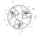
回転工具1は、図1~図5に示す限定されない一例のように、回転軸O1に沿って後端1aから先端1bにかけて延びてもよい。この回転工具1は、回転軸O1の周りで回転可能であってもよい。また、回転工具1は、フライス加工などに用いられる転削工具であってもよい。なお、図1などにおける矢印Y1は、回転軸O1の回転方向を示している。
The rotating
回転工具1は、ホルダ3及び切削インサート5(以下、「インサート5」ということがある)を有してもよい。The
ホルダ3は、回転軸O1に沿って延びた円柱形状であってもよい。円柱形状とは、概ね円柱形状であればよく、厳密な意味での円柱形状である必要はない。また、ホルダ3は、先端1bの側に位置するポケット7を有してもよい。ポケット7は、インサート5を取り付け可能な部位であってもよい。ポケット7は、ホルダ3の外周面及び先端1bの側の端面において開口してもよい。The
インサート5は、ポケット7に位置してもよい。なお、ポケット7は、1つのみであってもよく、また、複数であってもよい。図2に示す限定されない一例のように、ホルダ3が複数のポケット7を有する場合には、回転工具1が複数のインサート5を有してもよく、また、各ポケット7にインサート5が1つずつ位置してもよい。The
ホルダ3が複数のポケット7を有する場合において、これらのポケット7は、回転軸O1の周りにおいて等間隔で位置してもよく、また、不等間隔で位置してもよい。When the
ホルダ3は、特定の大きさに限定されない。例えば、回転軸O1に沿った方向におけるホルダ3の長さは、60~300mm程度に設定されてもよい。また、回転軸O1に直交する方向におけるホルダ3の幅(径)は、8~40mm程度に設定されてもよい。The
インサート5は、図6~図13に示す限定されない一例のように、上面9、下面11、側面13、上切刃15及び下切刃17を有してもよい。なお、上面9及び下面11は、便宜上の表現であり、上及び下の方向性を示すものではない。例えば、上面9は、インサート5を使用するときに上方を向く必要はない。これらの点は、上及び下の表現を含む他の部位においても同様である。The
上面9は、図2に示す限定されない一例のように、回転軸O1の回転方向Y1の前方に位置してもよい。また、上面9は、多角形状であってもよい。上面9は、図6に示す限定されない一例のように、概ね四角形状(長方形状)であってもよい。The
下面11は、上面9の反対側に位置してもよい。また、下面11は、上面9と同様に多角形状であってもよい。下面11は、概ね四角形状(長方形状)であってもよい。そして、インサート5は、多角板形状であってもよい。インサート5は、四角板形状であってもよい。The
なお、多角形状とは、厳密に多角形の形状である必要はない。例えば、上面9における複数の辺は、それぞれ厳密な直線でなくてもよく、上面9の正面視(上面視)において湾曲してもよい。また、互いに隣り合う辺の間に位置する上面9の角は、厳密な角でなくてもよい。言い換えれば、上面9における複数の角は、厳密な角でなくてもよい。角は、上面9を正面視した場合に、凸曲線形状であってもよく、また、直線及び曲線を組み合わせた形状であってもよい。
Note that the polygonal shape does not necessarily have to be a polygonal shape in the strict sense. For example, each of the multiple sides on the
上面9における複数の辺は、第1上辺19を含んでもよい。すなわち、上面9は、第1上辺19を有してもよい。第1上辺19は、先端1bの側に位置してもよい。上面9が、長辺及び短辺を有する四角形状である場合には、第1上辺19は短辺であってもよい。The multiple sides of the
下面11における複数の辺は、第1下辺21を含んでもよい。すなわち、下面11は、第1下辺21を有してもよい。第1下辺21は、先端1bの側に位置してもよい。下面11が、長辺及び短辺を有する四角形状である場合には、第1下辺21は短辺であってもよい。The multiple sides of the
上面9の中心及び下面11の中心を通る仮想直線が、インサート5の中心軸O2であってもよい。上面9が四角形状である場合には、上面9における対角線の交点を上面9の中心としてもよい。同様に、下面11が四角形状である場合には、下面11における対角線の交点を下面11の中心としてもよい。対角線の起点となるのは、四角形状を構成する各辺の延長線が交わる部分であってもよい。An imaginary line passing through the center of the
なお、上面9及び下面11の形状は、四角形状に限定されず、他の形状であってもよい。他の形状としては、例えば、三角形、五角形、六角形及び八角形などが挙げられ得る。上面9が四角形状でない場合には、例えば、上面9を正面視した場合における上面9の重心位置によって上面9の中心を特定してもよい。同様に、下面11が四角形状でない場合には、例えば、下面11を正面視(下面視)した場合における下面11の重心位置によって下面11の中心を特定してもよい。
The shapes of the
上面9は、上面9を正面視した場合において、中心軸O2を中心に180°の回転対称であってもよい。また、下面11は、下面11を正面視した場合において、中心軸O2を中心に180°の回転対称であってもよい。The
インサート5は、特定の大きさに限定されない。例えば、上面9を正面視した場合における最大幅は、6~25mm程度に設定されてもよい。また、上面9から下面11までの高さは、1~10mm程度に設定されてもよい。上面9から下面11までの高さとは、上面9及び下面11の間における中心軸O2に平行な方向での間隔の最大値を意味してもよい。また、上面9から下面11までの高さは、中心軸O2に沿った方向での側面13の幅と言い換えてもよい。The
側面13は、上面9及び下面11の間に位置してもよい。側面13は、図10に示す限定されない一例のように、上面9及び下面11に接続されてもよい。The
上切刃15は、第1上辺19に位置してもよい。上切刃15は、インサート5を用いて切削加工物を製造する際に、被削材を切削するために用いることが可能である。上切刃15は、第1上辺19の全体に位置してもよく、また、第1上辺19の一部のみに位置してもよい。The
インサート5が上切刃15を有する場合には、上面9及び側面13の一方がすくい面領域を有してもよく、また、上面9及び側面13のもう一方が逃げ面領域を有してもよい。図6に示す限定されない一例のように、上面9がすくい面領域を有し、且つ、側面13が逃げ面領域を有してもよい。When the
下切刃17は、第1下辺21に位置してもよい。下切刃17は、上切刃15と同様に、インサート5を用いて切削加工物を製造する際に、被削材を切削するために用いることが可能である。下切刃17は、第1下辺21の全体に位置してもよく、また、第1下辺21の一部のみに位置してもよい。なお、インサート5が上切刃15及び下切刃17を有する場合には、インサート5が両面仕様になり得る。The
ここで、側面13は、第1側面23、第2側面25及び第3側面27を有してもよい。第1側面23は、先端1bの側に位置してもよい。上切刃15を用いて切削加工物を製造する際に、第2側面25は、ホルダ3の外周側に位置してもよい。上切刃15を用いて切削加工物を製造する際に、第3側面27は、ホルダ3の内周側に位置してもよい。なお、第2側面25及び第3側面27は、回転軸O1に沿って位置してもよい。第3側面27は、第2側面25の反対側に位置してもよい。
Here, the
下切刃17を用いて切削加工物を製造する際においては、上切刃15を用いて切削加工物を製造する際と比較して、インサート5が反転された状態でホルダ3に装着されてもよい。そのため、下切刃17を用いて切削加工物を製造する際においては、第3側面27は、ホルダ3の外周側に位置してもよい。また、下切刃17を用いて切削加工物を製造する際においては、第2側面25は、ホルダ3の内周側に位置してもよい。When manufacturing a machined product using the
第1上辺19は、先端1bに向かって突出した凸形状であってもよい。また、第1上辺19は、先端1bの側に位置する第1端19aを有してもよい。より具体的には、第1上辺19は、第1上辺19における最も先端1bの側に位置する第1端19aを有してもよい。また、第1端19aは、第2側面25よりも第3側面27の近くに位置してもよい。言い換えれば、第1端19a及び第3側面27の間隔が、第1端19a及び第2側面25の間隔よりも小さくてもよい。The first
上切刃15のうち第1端19aの近くに位置する部分は、上切刃15を用いて切削加工物を製造する際に、被削材の加工面(仕上げ面)に沿って位置する底刃として用いることが可能である。上切刃15のうち第1端19aから第2側面25にかけて位置する部分は、上切刃15を用いて切削加工物を製造する際に、主として被削材を加工する、いわゆる主切刃として用いることが可能である。上切刃15のうち第1端19aから第3側面27にかけて位置する部分は、上切刃15を用いて斜め沈み込み加工を行う際に、斜め沈み込み刃として用いることが可能である。The portion of the
第1下辺21は、先端1bに向かって突出した凸形状であってもよい。また、第1下辺21は、先端1bの側に位置する第2端21aを有してもよい。より具体的には、第1下辺21は、第1下辺21における最も先端1bの側に位置する第2端21aを有してもよい。また、第2端21aは、第3側面27よりも第2側面25の近くに位置してもよい。言い換えれば、第2端21a及び第2側面25の間隔が、第2端21a及び第3側面27の間隔よりも小さくてもよい。The first
下切刃17のうち第2端21aの近くに位置する部分は、下切刃17を用いて切削加工物を製造する際に、被削材の加工面(仕上げ面)に沿って位置する底刃として用いることが可能である。下切刃17のうち第2端21aから第3側面27にかけて位置する部分は、下切刃17を用いて切削加工物を製造する際に、主として被削材を加工する、いわゆる主切刃として用いることが可能である。下切刃17のうち第2端21aから第2側面25にかけて位置する部分は、下切刃17を用いて斜め沈み込み加工を行う際に、斜め沈み込み刃として用いることが可能である。The portion of the
図7に示す限定されない一例のように、上面9の正面視において、第1側面23は、第1端19a及び第2端21aに挟まれた先端領域29を有してもよい。また、上面9の正面視において、先端領域29は、後端1aに向かって窪んでもよい。より具体的には、先端領域29は、上面9の正面視において、第1端19a及び第2端21aを結ぶ仮想直線L1よりも後端1aの側に位置するように後端1aに向かって窪んでもよい。7, in a front view of the
上面9の正面視において、先端領域29が後端1aに向かって窪んでいる場合には、先端領域29が直線状である場合と比較して、アキシャルレーキを小さな負の値にし易い。そのため、インサート5の側面13(第1側面23)が被削材に接触することを避けつつ、且つ、切削性が高い。When the
図8及び図12に示す限定されない一例のように、上面9の正面視において、第1端19aを通るとともに第1上辺19に直交する断面が、第1断面であってもよい。第1断面において、側面13(第1側面23)が凹形状であってもよい。この場合には、側面13(第1側面23)が被削材に接触しにくい。8 and 12, in a non-limiting example, a cross section passing through the
図8及び図13に示す限定されない一例のように、上面9の正面視において、第2端21aを通るとともに第1下辺21に直交する断面が、第2断面であってもよい。第2断面において、側面13(第1側面23)が凹形状であってもよい。この場合には、側面13(第1側面23)が被削材に接触しにくい。8 and 13, in a non-limiting example, a cross section passing through the
図11に示す限定されない一例のように、第1側面23の正面視(側面視)において、第1上辺19は、上方に向かって突出した凸形状であってもよい。また、第1側面23の正面視において、第1上辺19は、下面11から最も離れて位置する第3端19bを有してもよい。第1側面23の正面視において、第3端19bは、第2端21aの直上に位置してもよい。これらの場合には、上切刃15を用いて切削加工物を製造する際には、第3端19bによって第2端21aが被削材に接触しにくい。また、下切刃17を用いて切削加工物を製造する際には、第2端21aによって第3端19bが被削材に接触しにくい。As shown in a non-limiting example in FIG. 11, in a front view (side view) of the
なお、上記した第2端21aに対する第3端19bの位置関係は、第1側面23の正面視において、第2端21a及び第3端19bを結ぶ仮想直線L2が、中心軸O2に対して平行である、と言い換えてもよい。平行とは、厳密な平行に限定されず、±5°程度の傾斜を許容することを意味してもよい。In addition, the positional relationship of the
第1側面23の正面視において、第1下辺21は、下方に向かって突出した凸形状であってもよい。また、第1側面23の正面視において、第1下辺21は、上面9から最も離れて位置する第4端21bを有してもよい。第1側面23の正面視において、第4端21bは、第1端19aの直下に位置してもよい。これらの場合には、上切刃15を用いて切削加工物を製造する際には、第1端19aによって第4端21bが被削材に接触しにくい。また、下切刃17を用いて切削加工物を製造する際には、第4端21bによって第1端19aが被削材に接触しにくい。In a front view of the
なお、上記した第1端19aに対する第4端21bの位置関係は、第1側面23の正面視において、第1端19a及び第4端21bを結ぶ仮想直線L3が、中心軸O2に対して平行である、と言い換えてもよい。In addition, the positional relationship of the
上面9は、図7に示す限定されない一例のように、上傾斜面31、及び、上平坦面33を有してもよい。上傾斜面31は、上切刃15に沿って位置してもよい。また、上傾斜面31は、上切刃15から離れるにしたがって下面11に近づいてもよい。上平坦面33は、上傾斜面31よりも上面9の中央(中心)の近くに位置してもよい。上平坦面33は、平坦な面であってもよい。平坦とは、概ね平坦であればよく、厳密な意味での平坦である必要はない。
The
上傾斜面31は、上切刃15を用いて被削材を切削する際にすくい面領域として用いられてもよい。また、上平坦面33は、下切刃17を用いて被削材を切削する場合であって、インサート5をホルダ3に固定する際に、ホルダ3に当接(接触)する面として用いられてもよい。この場合、上平坦面33は座面として位置づけられてもよい。なお、上平坦面33は、中心軸O2に対して垂直であってもよい。垂直とは、厳密な垂直に限定されず、90°±5°程度の範囲を許容することを意味してもよい。The upper
上平坦面33は、先端1bの側に位置する第5端33aを有してもよい。より具体的には、上平坦面33は、上平坦面33における最も先端1bの側に位置する第5端33aを有してもよい。第5端33aは、第2側面25よりも第3側面27の近くに位置してもよい。言い換えれば、第5端33a及び第3側面27の間隔が、第5端33a及び第2側面25の間隔よりも小さくてもよい。上平坦面33がホルダ3への座面として用いられる場合において、第5端33aが上記に位置する際に、第5端33aが回転工具1における外周の近くに位置し易い。そのため、インサート5が安定してホルダ3に保持され易い。The upper
第3側面27は、第1端19aよりも第5端33aの近くに位置してもよい。言い換えれば、第3側面27及び第5端33aの間隔が、第3側面27及び第1端19aの間隔よりも小さくてもよい。上平坦面33が座面として用いられる場合において、第5端33aが上記に位置する際に、インサート5がより安定してホルダ3に保持され易い。The
下面11は、図9に示す限定されない一例のように、下傾斜面35、及び、下平坦面37を有してもよい。下傾斜面35は、下切刃17に沿って位置してもよい。また、下傾斜面35は、下切刃17から離れるにしたがって上面9に近づいてもよい。下平坦面37は、下傾斜面35よりも下面11の中央(中心)の近くに位置してもよい。下平坦面37は、平坦な面であってもよい。
The
下傾斜面35は、下切刃17を用いて被削材を切削する際にすくい面領域として用いられてもよい。また、下平坦面37は、上切刃15を用いて被削材を切削する場合であって、インサート5をホルダ3に固定する際に、ホルダ3に当接(接触)する面として用いられてもよい。この場合、下平坦面37は座面として位置づけられてもよい。なお、下平坦面37は、中心軸O2に対して垂直であってもよい。The lower
下平坦面37は、先端1bの側に位置する第6端37aを有してもよい。より具体的には、下平坦面37は、下平坦面37における最も先端1bの側に位置する第6端37aを有してもよい。第6端37aは、第3側面27よりも第2側面25の近くに位置してもよい。言い換えれば、第6端37a及び第2側面25の間隔が、第6端37a及び第3側面27の間隔よりも小さくてもよい。下平坦面37がホルダ3への座面として用いられる場合において、第6端37aが上記に位置する際に、第6端37aが回転工具1における外周の近くに位置し易い。そのため、インサート5が安定してホルダ3に保持され易い。The lower
第2側面25は、第2端21aよりも第6端37aの近くに位置してもよい。言い換えれば、第2側面25及び第6端37aの間隔が、第2側面25及び第2端21aの間隔よりも小さくてもよい。下平坦面37が座面として用いられる場合において、第6端37aが上記に位置する際に、インサート5がより安定してホルダ3に保持され易い。The
インサート5は、貫通孔39を有してもよい。貫通孔39は、インサート5をホルダ3に固定する際に、例えば、ネジを挿入するために用いることが可能である。なお、インサート5をホルダ3に固定する際には、ネジの代わりに、例えば、クランプ部材を用いてもよい。The
貫通孔39は、側面13における互いに反対側に位置する領域において開口してもよく、また、上面9及び下面11において開口してもよい。図6に示す限定されない一例のように、貫通孔39は、上面9の中心及び下面11の中心において開口してもよい。貫通孔39の中心軸は、上面9の中心及び下面11の中心を通る仮想直線であってもよい。言い換えれば、貫通孔39の中心軸は、インサート5の中心軸O2と一致してもよい。The through holes 39 may open in regions located on opposite sides of the
インサート5は、上切刃15又は下切刃17の少なくとも一部がホルダ3から突出するようにポケット7に装着されてもよい。例えば、インサート5は、上切刃15がホルダ3から被削材に向かって突出するようにホルダ3に装着されてもよい。この場合には、下面11及び側面13がホルダ3に当接してもよい。The
インサート5は、ネジ41によって、ポケット7に装着されてもよい。すなわち、インサート5の貫通孔39にネジ41を挿入し、このネジ41の先端をポケット7に形成されたネジ孔に挿入して、ネジ41をネジ孔に固定させることによって、インサート5がホルダ3に装着されてもよい。The
ホルダ3の材質としては、例えば、鋼及び鋳鉄などが挙げられ得る。ホルダ3の材質が鋼の場合には、ホルダ3の靱性が高い。
Materials for the
インサート5の材質としては、例えば、超硬合金及びサーメットなどが挙げられ得る。超硬合金の組成としては、例えば、WC-Co、WC-TiC-Co及びWC-TiC-TaC-Coが挙げられ得る。ここで、WC、TiC及びTaCは硬質粒子であってもよく、また、Coは結合相であってもよい。
Materials for the
また、サーメットは、セラミック成分に金属を複合させた焼結複合材料であってもよい。サーメットの一例として、炭化チタン(TiC)又は窒化チタン(TiN)を主成分としたチタン化合物が挙げられ得る。インサート5の材質が上記の組成に限定されないことは言うまでもない。The cermet may also be a sintered composite material in which a ceramic component is combined with a metal. An example of a cermet is a titanium compound mainly composed of titanium carbide (TiC) or titanium nitride (TiN). It goes without saying that the material of the
インサート5の表面は、化学蒸着(CVD)法又は物理蒸着(PVD)法を用いて被膜でコーティングされてもよい。被膜の組成としては、例えば、炭化チタン(TiC)、窒化チタン(TiN)、炭窒化チタン(TiCN)及びアルミナ(Al2O3)などが挙げられ得る。
The surface of the
<切削加工物の製造方法>
次に、本開示の限定されない一面の切削加工物203の製造方法について図14~図16を用いて説明する。
<Method of manufacturing machined product>
Next, a non-limiting method for manufacturing the one-sided
切削加工物203は、被削材201を切削加工することによって作製されてもよい。切削加工物203の製造方法は、以下の工程を備えてもよい。すなわち、
(1)上記の限定されない実施形態に代表される回転工具1を回転させる工程と、
(2)回転する回転工具1を被削材201に接触させる工程と、
(3)回転工具1を被削材201から離す工程と、
を備えてもよい。
The
(1) rotating a
(2) a step of bringing the
(3) a step of separating the
The present invention may also include:
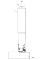
具体的には、まず、図14に示す限定されない一例のように、回転工具1を回転軸O1の周りでY1方向に回転させながら被削材201に相対的に近づけてもよい。次に、図15に示す限定されない一例のように、回転工具1における上切刃15を被削材201に接触させて、被削材201を切削してもよい。そして、図16に示す限定されない一例のように、回転工具1を被削材201から相対的に遠ざけてもよい。Specifically, first, the
以上のような工程を経る場合には、優れた加工性を発揮することが可能となる。具体的には、本開示の限定されない一面の切削加工物203の製造方法において、回転工具1を用いる場合には、インサート5の側面13が被削材201に接触することを避けつつ、且つ、切削性が高い。そのため、仕上げ面の精度が高い切削加工物203を得ることが可能となる。
When the above-mentioned steps are performed, it becomes possible to exhibit excellent workability. Specifically, in the manufacturing method of the one-sided
なお、図14~図16に示す限定されない一例では、それぞれの工程において、被削材201を固定するとともに回転工具1を動かしているが、当然ながらこのような形態に限定されない。In the non-limiting example shown in Figures 14 to 16, the
例えば、(1)の工程において、被削材201を回転工具1に近づけてもよい。同様に、(3)の工程において、被削材201を回転工具1から遠ざけてもよい。切削加工を継続する場合には、回転工具1を回転させた状態を維持して、被削材201の異なる箇所にインサート5の上切刃15を接触させる工程を繰り返してもよい。For example, in step (1), the
被削材201の材質としては、例えば、炭素鋼、合金鋼、ステンレス、鋳鉄及び非鉄金属などが挙げられ得る。
Examples of materials for the
1・・・回転工具
1a・・後端
1b・・先端
3・・・ホルダ
5・・・切削インサート(インサート)
7・・・ポケット
9・・・上面
11・・・下面
13・・・側面
15・・・上切刃
17・・・下切刃
19・・・第1上辺
19a・・第1端
19b・・第3端
21・・・第1下辺
21a・・第2端
21b・・第4端
23・・・第1側面
25・・・第2側面
27・・・第3側面
29・・・先端領域
31・・・上傾斜面
33・・・上平坦面
33a・・第5端
35・・・下傾斜面
37・・・下平坦面
37a・・第6端
39・・・貫通孔
41・・・ネジ
201・・・被削材
203・・・切削加工物
O1・・・回転軸
O2・・・中心軸
Reference Signs List 1: Rotating
Reference Signs List 7: Pocket 9: Upper surface 11: Lower surface 13: Side surface 15: Upper cutting edge 17: Lower cutting edge 19: First
Claims (9)
前記回転軸に沿って延びた円柱形状であるとともに、前記先端の側に位置するポケットを有するホルダと、
前記ポケットに位置する切削インサートと、を有し、
前記切削インサートは、
前記回転軸の回転方向の前方に位置するとともに、前記先端の側に位置する第1上辺を有する上面と、
前記上面の反対側に位置するとともに、前記先端の側に位置する第1下辺を有する下面と、
前記上面及び前記下面の間に位置する側面と、
前記第1上辺に位置する上切刃と、
前記第1下辺に位置する下切刃と、を有し、
前記側面は、
前記先端の側に位置する第1側面と、
前記ホルダの外周側に位置する第2側面と、
前記第2側面の反対側に位置する第3側面と、を有し、
前記第1上辺は、前記先端に向かって突出した凸形状であって、前記先端の側に位置する第1端を有し、
前記第1端は、前記第2側面よりも前記第3側面の近くに位置し、
前記第1下辺は、前記先端に向かって突出した凸形状であって、前記先端の側に位置する第2端を有し、
前記第2端は、前記第3側面よりも前記第2側面の近くに位置し、
前記上面の正面視において、前記第1側面は、前記第1端及び前記第2端に挟まれた先端領域を有し、前記先端領域は、前記後端に向かって窪み、
前記第1側面の正面視において、
前記第1上辺は、上方に向かって突出した凸形状であって、前記下面から最も離れて位置する第3端を有し、
前記第3端は、前記第2端の直上に位置する、回転工具。 A rotary tool extending from a rear end to a front end along a rotary shaft,
a holder having a cylindrical shape extending along the rotation axis and having a pocket located on the tip side;
a cutting insert located in the pocket;
The cutting insert comprises:
an upper surface having a first upper side located forward in a rotation direction of the rotation shaft and on the side of the tip;
a lower surface located opposite the upper surface and having a first lower side located on the tip side;
A side surface located between the upper surface and the lower surface;
An upper cutting edge located on the first upper side;
A lower cutting edge located on the first lower side,
The aspect is
A first side surface located on the tip side;
A second side surface located on an outer circumferential side of the holder;
a third side opposite the second side,
the first upper side has a convex shape protruding toward the tip and has a first end located on the tip side;
the first end is located closer to the third side surface than to the second side surface;
the first lower side has a convex shape protruding toward the tip and has a second end located on the tip side;
the second end is located closer to the second side surface than to the third side surface;
When viewed from the front of the top surface, the first side surface has a tip region sandwiched between the first end and the second end, the tip region being recessed toward the rear end,
In a front view of the first side surface,
the first upper side has a convex shape protruding upward and has a third end located furthest from the lower surface;
The third end is located directly above the second end.
前記第1断面において、前記側面が凹形状である、請求項1に記載の回転工具。 In a front view of the upper surface, a cross section passing through the first end and perpendicular to the first upper side is a first cross section,
The rotary tool of claim 1 , wherein in the first cross section, the side surface is concave.
前記第2断面において、前記側面が凹形状である、請求項1又は2に記載の回転工具。 In a front view of the upper surface, a cross section passing through the second end and perpendicular to the first lower side is a second cross section,
The rotary tool according to claim 1 or 2, wherein in the second cross section, the side surface is concave.
前記第1下辺は、下方に向かって突出した凸形状であって、前記上面から最も離れて位置する第4端を有し、
前記第4端は、前記第1端の直下に位置する、請求項1~3のいずれか1つに記載の回転工具。 In a front view of the first side surface,
the first lower side has a convex shape that protrudes downward and has a fourth end that is located furthest from the upper surface;
The rotary tool according to any one of claims 1 to 3, wherein the fourth end is located immediately below the first end.
前記上切刃に沿って位置するとともに、前記上切刃から離れるにしたがって前記下面に近づく上傾斜面と、
前記上傾斜面よりも前記上面の中央の近くに位置する平坦な上平坦面と、を有し、
前記上平坦面は、前記先端の側に位置する第5端を有し、
前記第5端は、前記第2側面よりも前記第3側面の近くに位置する、請求項1~4のいずれか1つに記載の回転工具。 The upper surface is
an upper inclined surface that is located along the upper cutting edge and approaches the lower surface as it moves away from the upper cutting edge;
a flat upper flat surface located closer to the center of the upper surface than the upper inclined surface;
the upper planar surface has a fifth end located on the tip side;
The rotary tool according to any one of claims 1 to 4, wherein the fifth end is located closer to the third side surface than to the second side surface.
前記下切刃に沿って位置するとともに、前記下切刃から離れるにしたがって前記上面に近づく下傾斜面と、
前記下傾斜面よりも前記下面の中央の近くに位置する平坦な下平坦面と、を有し、
前記下平坦面は、前記先端の側に位置する第6端を有し、
前記第6端は、前記第3側面よりも前記第2側面の近くに位置する、請求項1~6のいずれか1つに記載の回転工具。 The lower surface is
a lower inclined surface located along the lower cutting edge and approaching the upper surface as it moves away from the lower cutting edge;
a lower flat surface located closer to the center of the lower surface than the lower inclined surface;
The lower planar surface has a sixth end located on the tip side,
The rotary tool according to any one of claims 1 to 6, wherein the sixth end is located closer to the second side surface than to the third side surface.
回転する前記回転工具を被削材に接触させる工程と、
前記回転工具を前記被削材から離す工程と、を備えた切削加工物の製造方法。 A step of rotating the rotary tool according to any one of claims 1 to 8;
bringing the rotating rotary tool into contact with a workpiece;
and removing the rotating tool from the workpiece.
Applications Claiming Priority (3)
| Application Number | Priority Date | Filing Date | Title |
|---|---|---|---|
| JP2020054294 | 2020-03-25 | ||
| JP2020054294 | 2020-03-25 | ||
| PCT/JP2021/012197 WO2021193705A1 (en) | 2020-03-25 | 2021-03-24 | Rotating tool and method for manufacturing cut workpieces |
Publications (2)
| Publication Number | Publication Date |
|---|---|
| JPWO2021193705A1 JPWO2021193705A1 (en) | 2021-09-30 |
| JP7488332B2 true JP7488332B2 (en) | 2024-05-21 |
Family
ID=77890454
Family Applications (1)
| Application Number | Title | Priority Date | Filing Date |
|---|---|---|---|
| JP2022510595A Active JP7488332B2 (en) | 2020-03-25 | 2021-03-24 | Method for manufacturing rotary tools and machined products |
Country Status (6)
| Country | Link |
|---|---|
| US (1) | US20230373019A1 (en) |
| JP (1) | JP7488332B2 (en) |
| KR (1) | KR20220134654A (en) |
| CN (1) | CN115243816A (en) |
| DE (1) | DE112021001815T5 (en) |
| WO (1) | WO2021193705A1 (en) |
Citations (3)
| Publication number | Priority date | Publication date | Assignee | Title |
|---|---|---|---|---|
| WO2011122676A1 (en) | 2010-03-30 | 2011-10-06 | 三菱マテリアル株式会社 | Cutting insert and cutting tool with interchangeable cutting point |
| JP2013176834A (en) | 2011-12-12 | 2013-09-09 | Mitsubishi Materials Corp | Cutting insert and interchangeable cutting edge-type cutting tool |
| JP2015521958A (en) | 2012-07-06 | 2015-08-03 | イスカル リミテッド | Rotary cutting tool and reversible cutting insert |
Family Cites Families (2)
| Publication number | Priority date | Publication date | Assignee | Title |
|---|---|---|---|---|
| CN102458741B (en) | 2009-04-02 | 2014-06-25 | 株式会社钨钛合金 | Cutting insert and indexable cutting tool |
| JP5888656B2 (en) | 2014-06-02 | 2016-03-22 | 住友電工ハードメタル株式会社 | Cutting insert and milling cutter |
-
2021
- 2021-03-24 JP JP2022510595A patent/JP7488332B2/en active Active
- 2021-03-24 CN CN202180019420.2A patent/CN115243816A/en active Pending
- 2021-03-24 US US17/913,432 patent/US20230373019A1/en active Pending
- 2021-03-24 KR KR1020227031746A patent/KR20220134654A/en active IP Right Grant
- 2021-03-24 DE DE112021001815.9T patent/DE112021001815T5/en active Pending
- 2021-03-24 WO PCT/JP2021/012197 patent/WO2021193705A1/en active Application Filing
Patent Citations (3)
| Publication number | Priority date | Publication date | Assignee | Title |
|---|---|---|---|---|
| WO2011122676A1 (en) | 2010-03-30 | 2011-10-06 | 三菱マテリアル株式会社 | Cutting insert and cutting tool with interchangeable cutting point |
| JP2013176834A (en) | 2011-12-12 | 2013-09-09 | Mitsubishi Materials Corp | Cutting insert and interchangeable cutting edge-type cutting tool |
| JP2015521958A (en) | 2012-07-06 | 2015-08-03 | イスカル リミテッド | Rotary cutting tool and reversible cutting insert |
Also Published As
| Publication number | Publication date |
|---|---|
| US20230373019A1 (en) | 2023-11-23 |
| WO2021193705A1 (en) | 2021-09-30 |
| CN115243816A (en) | 2022-10-25 |
| KR20220134654A (en) | 2022-10-05 |
| JPWO2021193705A1 (en) | 2021-09-30 |
| DE112021001815T5 (en) | 2023-01-05 |
Similar Documents
| Publication | Publication Date | Title |
|---|---|---|
| KR101700703B1 (en) | Cutting insert, cutting tool, and method for manufacturing cut workpiece using same | |
| JP6356781B2 (en) | Cutting insert, cutting tool, and manufacturing method of cut workpiece | |
| JP5591409B2 (en) | Cutting insert, cutting tool and method of manufacturing workpiece | |
| JP6386524B2 (en) | Cutting insert for turning tool, turning tool, and method for producing cut product | |
| JP7417713B2 (en) | Manufacturing method for cutting inserts, cutting tools, and cut products | |
| US20210260669A1 (en) | Cutting insert, cutting tool, and method for manufacturing machined product | |
| JP7480291B2 (en) | Method for manufacturing cutting insert, cutting tool, and machined product | |
| JP6185376B2 (en) | Cutting insert, cutting tool and method of manufacturing workpiece | |
| JP6810807B2 (en) | Manufacturing method for cutting inserts, cutting tools and cutting products | |
| JP7488332B2 (en) | Method for manufacturing rotary tools and machined products | |
| JP7114733B2 (en) | Manufacturing method of cutting insert, cutting tool and cutting work | |
| WO2019022016A1 (en) | Cutting insert, cutting tool, and method for producing cut workpiece | |
| KR102540681B1 (en) | Methods for manufacturing cutting inserts, cutting tools and cutting components | |
| WO2023176618A1 (en) | Cutting insert, cutting tool, and method for manufacturing cut workpiece | |
| JP7344168B2 (en) | Manufacturing method for cutting inserts, cutting tools, and cut products | |
| JP5762020B2 (en) | Cutting insert, cutting tool, and cutting method of work material using the same | |
| WO2023228741A1 (en) | Cutting tool and method for producing cut workpiece | |
| JP7223773B2 (en) | Manufacturing method for rotary tool and cut product | |
| JP6717951B2 (en) | Manufacturing method of cutting insert, cutting tool, and cut product | |
| JP2012232351A (en) | Cutting insert, cutting tool, and method of cutting workpiece to be cut using the same | |
| CN117999139A (en) | Cutting insert, cutting tool, and method for manufacturing cut product |
Legal Events
| Date | Code | Title | Description |
|---|---|---|---|
| A621 | Written request for application examination |
Free format text: JAPANESE INTERMEDIATE CODE: A621 Effective date: 20220901 |
|
| A131 | Notification of reasons for refusal |
Free format text: JAPANESE INTERMEDIATE CODE: A131 Effective date: 20230905 |
|
| A521 | Request for written amendment filed |
Free format text: JAPANESE INTERMEDIATE CODE: A523 Effective date: 20231027 |
|
| A131 | Notification of reasons for refusal |
Free format text: JAPANESE INTERMEDIATE CODE: A131 Effective date: 20240116 |
|
| A521 | Request for written amendment filed |
Free format text: JAPANESE INTERMEDIATE CODE: A523 Effective date: 20240126 |
|
| TRDD | Decision of grant or rejection written | ||
| A01 | Written decision to grant a patent or to grant a registration (utility model) |
Free format text: JAPANESE INTERMEDIATE CODE: A01 Effective date: 20240430 |
|
| A61 | First payment of annual fees (during grant procedure) |
Free format text: JAPANESE INTERMEDIATE CODE: A61 Effective date: 20240509 |
|
| R150 | Certificate of patent or registration of utility model |
Ref document number: 7488332 Country of ref document: JP Free format text: JAPANESE INTERMEDIATE CODE: R150 |