JP7477780B2 - Communication device and error detection method - Google Patents
Communication device and error detection method Download PDFInfo
- Publication number
- JP7477780B2 JP7477780B2 JP2021577782A JP2021577782A JP7477780B2 JP 7477780 B2 JP7477780 B2 JP 7477780B2 JP 2021577782 A JP2021577782 A JP 2021577782A JP 2021577782 A JP2021577782 A JP 2021577782A JP 7477780 B2 JP7477780 B2 JP 7477780B2
- Authority
- JP
- Japan
- Prior art keywords
- unit
- communication
- onu
- communication device
- error
- Prior art date
- Legal status (The legal status is an assumption and is not a legal conclusion. Google has not performed a legal analysis and makes no representation as to the accuracy of the status listed.)
- Active
Links
- 238000004891 communication Methods 0.000 title claims description 153
- 238000001514 detection method Methods 0.000 title claims description 3
- 238000012544 monitoring process Methods 0.000 claims description 105
- 238000000034 method Methods 0.000 claims description 20
- 230000003287 optical effect Effects 0.000 claims description 18
- 238000012545 processing Methods 0.000 description 46
- 238000010586 diagram Methods 0.000 description 16
- 238000012423 maintenance Methods 0.000 description 12
- 230000006870 function Effects 0.000 description 4
- 238000011084 recovery Methods 0.000 description 4
- 238000012986 modification Methods 0.000 description 2
- 230000004048 modification Effects 0.000 description 2
- 230000002159 abnormal effect Effects 0.000 description 1
- JJWKPURADFRFRB-UHFFFAOYSA-N carbonyl sulfide Chemical compound O=C=S JJWKPURADFRFRB-UHFFFAOYSA-N 0.000 description 1
- 238000006243 chemical reaction Methods 0.000 description 1
- 238000005516 engineering process Methods 0.000 description 1
- 230000010365 information processing Effects 0.000 description 1
- 239000004973 liquid crystal related substance Substances 0.000 description 1
- 230000002093 peripheral effect Effects 0.000 description 1
- 239000007787 solid Substances 0.000 description 1
Images


Classifications
-
- H—ELECTRICITY
- H04—ELECTRIC COMMUNICATION TECHNIQUE
- H04B—TRANSMISSION
- H04B10/00—Transmission systems employing electromagnetic waves other than radio-waves, e.g. infrared, visible or ultraviolet light, or employing corpuscular radiation, e.g. quantum communication
- H04B10/07—Arrangements for monitoring or testing transmission systems; Arrangements for fault measurement of transmission systems
- H04B10/075—Arrangements for monitoring or testing transmission systems; Arrangements for fault measurement of transmission systems using an in-service signal
- H04B10/077—Arrangements for monitoring or testing transmission systems; Arrangements for fault measurement of transmission systems using an in-service signal using a supervisory or additional signal
- H04B10/0773—Network aspects, e.g. central monitoring of transmission parameters
-
- H—ELECTRICITY
- H04—ELECTRIC COMMUNICATION TECHNIQUE
- H04B—TRANSMISSION
- H04B10/00—Transmission systems employing electromagnetic waves other than radio-waves, e.g. infrared, visible or ultraviolet light, or employing corpuscular radiation, e.g. quantum communication
- H04B10/07—Arrangements for monitoring or testing transmission systems; Arrangements for fault measurement of transmission systems
- H04B10/075—Arrangements for monitoring or testing transmission systems; Arrangements for fault measurement of transmission systems using an in-service signal
- H04B10/079—Arrangements for monitoring or testing transmission systems; Arrangements for fault measurement of transmission systems using an in-service signal using measurements of the data signal
- H04B10/0793—Network aspects, e.g. central monitoring of transmission parameters
-
- H—ELECTRICITY
- H04—ELECTRIC COMMUNICATION TECHNIQUE
- H04B—TRANSMISSION
- H04B10/00—Transmission systems employing electromagnetic waves other than radio-waves, e.g. infrared, visible or ultraviolet light, or employing corpuscular radiation, e.g. quantum communication
- H04B10/07—Arrangements for monitoring or testing transmission systems; Arrangements for fault measurement of transmission systems
- H04B10/075—Arrangements for monitoring or testing transmission systems; Arrangements for fault measurement of transmission systems using an in-service signal
- H04B10/079—Arrangements for monitoring or testing transmission systems; Arrangements for fault measurement of transmission systems using an in-service signal using measurements of the data signal
- H04B10/0799—Monitoring line transmitter or line receiver equipment
-
- H—ELECTRICITY
- H04—ELECTRIC COMMUNICATION TECHNIQUE
- H04Q—SELECTING
- H04Q11/00—Selecting arrangements for multiplex systems
- H04Q11/0001—Selecting arrangements for multiplex systems using optical switching
- H04Q11/0062—Network aspects
- H04Q11/0067—Provisions for optical access or distribution networks, e.g. Gigabit Ethernet Passive Optical Network (GE-PON), ATM-based Passive Optical Network (A-PON), PON-Ring
-
- H—ELECTRICITY
- H04—ELECTRIC COMMUNICATION TECHNIQUE
- H04Q—SELECTING
- H04Q11/00—Selecting arrangements for multiplex systems
- H04Q11/0001—Selecting arrangements for multiplex systems using optical switching
- H04Q11/0062—Network aspects
- H04Q2011/0079—Operation or maintenance aspects
- H04Q2011/0083—Testing; Monitoring
Landscapes
- Engineering & Computer Science (AREA)
- Computer Networks & Wireless Communication (AREA)
- Physics & Mathematics (AREA)
- Electromagnetism (AREA)
- Signal Processing (AREA)
- Maintenance And Management Of Digital Transmission (AREA)
- Debugging And Monitoring (AREA)
Description
本発明は、通信装置及びエラー検出方法に関する。 The present invention relates to a communication device and an error detection method.
従来、自己の装置の故障及び自己の装置内部を流れるデータに生じたエラー(以下、総称して「エラー」という。)を検出することができる装置がある(例えば、特許文献1参照)。このような装置の一例を図10に示す。図10は、従来の通信装置の一例を示す概略構成図である。図示されるように、図10において、通信装置はONU(Optical Network Unit)である。ONUは、主信号処理部と、制御部/装置監視部とを備えている。主信号処理部は、OLT(Optical Line Terminal)とユーザ端末との間を流れる主信号に対して、光信号と電気信号の相互変換等の処理を行う。制御部/装置監視部は、自己の通信装置内部を流れるデータの整合性をチェックすることにより、エラーを検出する。例えば、制御部/装置監視部は、主信号処理部を流れる主信号を監視してエラーを検出する。そして、制御部/装置監視部は、検出されたエラーを訂正する。Conventionally, there are devices that can detect failures in their own devices and errors (hereinafter collectively referred to as "errors") that occur in data flowing inside the own devices (see, for example, Patent Document 1). An example of such a device is shown in FIG. 10. FIG. 10 is a schematic configuration diagram showing an example of a conventional communication device. As shown in the figure, in FIG. 10, the communication device is an ONU (Optical Network Unit). The ONU has a main signal processing unit and a control unit/device monitoring unit. The main signal processing unit performs processing such as mutual conversion between optical signals and electrical signals for the main signal flowing between the OLT (Optical Line Terminal) and the user terminal. The control unit/device monitoring unit detects errors by checking the consistency of data flowing inside the own communication device. For example, the control unit/device monitoring unit monitors the main signal flowing through the main signal processing unit to detect errors. Then, the control unit/device monitoring unit corrects the detected error.
前述の通り、従来の通信装置は、制御部/装置監視部を備えることでエラーを検出することができる。しかしながら、従来の通信装置は、自己の通信装置を監視するデバイス(すなわち、制御部/装置監視部を有するデバイス)を暴走又は動作停止させるようなエラーが生じた場合には、当該エラーを検出することができないという課題がある。As mentioned above, conventional communication devices are capable of detecting errors by being equipped with a control unit/device monitoring unit. However, conventional communication devices have a problem in that when an error occurs that causes a device that monitors the communication device (i.e., a device that has a control unit/device monitoring unit) to go out of control or stop working, the device is unable to detect the error.
本発明は、上記の点を鑑みてなされたものであり、自己の通信装置を監視するデバイスにおいてエラーが生じた場合であっても、当該エラーを検出することができる技術を提供することを目的とする。The present invention has been made in consideration of the above points, and aims to provide technology that can detect errors even when such errors occur in a device that monitors one's own communication equipment.
本発明の一態様は、複数のデバイスを備え、各々の前記デバイスは、少なくとも1つの他のデバイスを監視して、前記他のデバイスにおいて生じたエラーを検出する監視部を備え、各々の前記デバイスは、少なくとも1つの他のデバイスによって監視される通信装置である。One aspect of the present invention is a communications device comprising a plurality of devices, each of which has a monitoring unit that monitors at least one other device and detects errors occurring in the other device, and each of which is a communications device monitored by at least one other device.
また、本発明の一態様は、複数のデバイスを備え、各々の前記デバイスが少なくとも1つの他のデバイスによって監視される通信装置によるエラー検出方法であって、少なくとも1つの他のデバイスを監視して、前記他のデバイスにおいて生じたエラーを検出するステップを有するエラー検出方法である。Another aspect of the present invention is a method for detecting an error using a communication device having a plurality of devices, each of which is monitored by at least one other device, the method including a step of monitoring the at least one other device and detecting an error that has occurred in the other device.
本発明により、自己の通信装置を監視するデバイスにおいてエラーが生じた場合であっても、当該エラーを検出することができる。 The present invention makes it possible to detect errors even if they occur in a device that monitors one's own communication equipment.
<第1の実施形態>
以下、本発明の第1の実施形態について、図面を参照しながら説明する。
First Embodiment
Hereinafter, a first embodiment of the present invention will be described with reference to the drawings.
[通信システムの全体構成]
図1は、本発明の第1の実施形態に係る通信システム1の全体構成図である。図1に示される通信システム1は、10G-EPON(10 Gigabit-Ethernet Passive Optical Network)システムである。図示されるように、通信システム1は、複数のONU100と、各ONU100にそれぞれ通信接続された複数のユーザ端末200と、OLT300と、光スプリッタ400とを含んで構成される。通信システム1は、1つのOLT300と複数のONU100とが光スプリッタ400を介してPoint-to-Multipoint型に通信接続されたシステムである。但し、通信システム1は、OLT300とONU100とがそれぞれ1つずつであり、Point-to-Point型に通信接続されたシステムであっても構わない。ユーザ端末200とは、例えば、パソコン又はホームゲートウェイ等の情報処理装置である。
[Overall configuration of communication system]
FIG. 1 is an overall configuration diagram of a
[ONUの構成]
図2は、本発明の第1の実施形態に係るONU100の機能構成を示す概略ブロック図である。図2に示されるように、ONU100は、デバイス110aと、デバイス110bと、光受電部120と、UNI(User Network Interface)130と、電源部140とを含んで構成される。なお、図2において、実線の矢印は、主信号が流れる通信線を表す。また、破線の矢印は、制御信号が流れる制御信号線を表す。
[ONU Configuration]
Fig. 2 is a schematic block diagram showing a functional configuration of an ONU 100 according to a first embodiment of the present invention. As shown in Fig. 2, the ONU 100 includes a
デバイス110aは、主信号処理部111aと、制御部/装置監視部112aとを含んで構成される。また、デバイス110bは、主信号処理部111bと、制御部/装置監視部112bとを含んで構成される。このように、デバイス110aとデバイス110bとは同様の構成である。なお、デバイス110aとデバイス110bとを特に区別して説明する必要がない場合には、以下、単に「デバイス110」という。また、主信号処理部111aと主信号処理部111bとを特に区別して説明する必要がない場合には、以下、単に「主信号処理部111」という。また、制御部/装置監視部112aと制御部/装置監視部112bとを特に区別して説明する必要がない場合には、以下、単に「制御部/装置監視部112」という。
主信号処理部111は、OLT(Optical Line Terminal)300とユーザ端末200との間を流れる主信号に対して、光信号と電気信号の相互変換等の処理を行う。The main signal processing unit 111 performs processing such as converting between optical signals and electrical signals on the main signal flowing between the OLT (Optical Line Terminal) 300 and the
制御部/装置監視部112aは、例えばCPU(Central Processing Unit)等のプロセッサを含んで構成される。制御部/装置監視部112aは、ONU100が備える各機能部の動作を制御する。また、制御部/装置監視部112aは、主信号処理部111aを流れる主信号を監視することにより、主信号に生じたエラーを検出する。また、制御部/装置監視部112aは、制御信号線を介して他方のデバイス110(すなわち、デバイス110b)の死活監視を実行する。また、制御部/装置監視部112aは、他方のデバイス110の暴走又は動作停止を検出した場合、制御信号線を介して他方のデバイス110へリセット指示を出力する。又は、制御部/装置監視部112aは、他方のデバイス110の暴走又は動作停止を検出した場合、制御信号線を介して電源部140へ電源リセット指示を出力する。また、制御部/装置監視部112aは、他方のデバイス110の制御部/装置監視部112(すなわち、制御部/装置監視部112b)から制御信号線を介してリセット指示を取得した場合、自己のデバイス110aの動作状態をリセットするリセット処理を実行する。The control unit/
制御部/装置監視部112bは、例えばCPU等のプロセッサを含んで構成される。制御部/装置監視部112bは、ONU100が備える各機能部の動作を制御する。また、制御部/装置監視部112bは、主信号処理部111bを流れる主信号を監視することにより、主信号に生じたエラーを検出する。また、制御部/装置監視部112bは、制御信号線を介して他方のデバイス110(すなわち、デバイス110a)の死活監視を実行する。また、制御部/装置監視部112bは、他方のデバイス110の暴走又は動作停止を検出した場合、制御信号線を介して他方のデバイス110へリセット指示を出力する。又は、制御部/装置監視部112bは、他方のデバイス110の暴走又は動作停止を検出した場合、制御信号線を介して電源部140へ電源リセット指示を出力する。また、制御部/装置監視部112bは、他方のデバイス110の制御部/装置監視部112(すなわち、制御部/装置監視部112a)から制御信号線を介してリセット指示を取得した場合、自己のデバイス110bの動作状態をリセットするリセット処理を実行する。The control unit/
光受電部120は、OLT300から送信された光信号を受電し、主信号処理部111へ出力する。また、光受電部120は、主信号処理部111から出力された光信号をOLT300へ送信する。
UNI130は、主信号処理部111から出力された電気信号をユーザ端末200へ送信する。また、UNI130は、ユーザ端末200から送信された電気信号を主信号処理部11へ出力する。
The
The UNI 130 transmits the electrical signal output from the main signal processing unit 111 to the
電源部140は、ONU100が備える各機能部へ電力を供給する。また、電源部140は、制御部/装置監視部112から制御信号線を介してリセット指示を取得した場合、ONU100全体への電力の供給を一旦停止にした後(すなわち、電源オフにした後)、ONU100全体への電力の供給を再開する(すなわち、電源オンにする)電源リセット処理を実行する。The
なお、デバイス110のリセット、及びONU100全体の電源リセットを行わせる方法については、任意の方法を用いることができる。
Any method can be used to reset device 110 and to perform a power reset of the
[デバイスの動作]
図3は、本発明の第1の実施形態に係るデバイス110の動作を示すフローチャートである。図3に示されるフローチャートは、他方のデバイス110においてエラーが生じた場合に開始する。なお、以下の説明では、例としてデバイス110aの動作を説明するが、デバイス110bの動作も同様である。
[Device Operation]
Fig. 3 is a flowchart showing the operation of the device 110 according to the first embodiment of the present invention. The flowchart shown in Fig. 3 starts when an error occurs in the other device 110. Note that in the following description, the operation of the
デバイス110aの制御部/装置監視部112aは、他方のデバイス110(デバイス110b)において生じたエラーを検出する(ステップS001)。前述の通り、ここでいうエラーとは、例えばデバイス110の暴走又は動作停止等である。次に、制御部/装置監視部112aは、制御信号線を介して他方のデバイス110(デバイス110b)へリセット指示を出力する(ステップS002)。The control unit/
次に、制御部/装置監視部112aは、リセット処理によって他方のデバイス110(デバイス110b)が復旧したことを検出した場合(ステップS003・Yes)、図3のフローチャートが示すデバイス110aの動作が終了する。一方、制御部/装置監視部112aは、他方のデバイス110(デバイス110b)が復旧していないことを検出した場合(ステップS003・No)、制御信号線を介して電源部140へ電源リセット指示を出力する(ステップS004)。以上で、図3のフローチャートが示すデバイス110aの動作が終了する。Next, if the control unit/
以上説明したように、第1の実施形態に係るONU100(通信装置)は、自己の通信装置内の複数のデバイス110(通信処理部)で相互に監視を行う。そして、ONU100は、一方のデバイス110においてエラーが生じ、一方のデバイス110が暴走又は動作停止等をした場合に、他方のデバイス110によって一方のデバイス110の動作状態をリセットさせる。又は、デバイス110が暴走又は動作停止等をした場合に、ONU100は、自己の通信装置(ONU)100全体の電源をリセットさせる。As described above, the ONU 100 (communication device) according to the first embodiment mutually monitors the multiple devices 110 (communication processing units) within its own communication device. If an error occurs in one of the devices 110, causing the other device 110 to go out of control or stop working, the
なお、従来の通信装置では、例えばビット反転が生じるようなソフトエラーが生じた場合に、自己の通信装置内部のデバイスでエラーを検出して訂正することを想定している。しかしながら、従来の通信装置は、自己の通信装置を監視するデバイスにおいて例えば、デバイス自身を暴走又は動作停止等を生じさせるようなソフトエラーが発生した場合には、当該ソフトエラーを検出することができない。 In conventional communication devices, when a soft error occurs, such as when a bit inversion occurs, it is assumed that the error will be detected and corrected in a device within the communication device. However, when a soft error occurs in a device that monitors the communication device, such as when the device itself goes out of control or stops working, the conventional communication device is unable to detect the soft error.
これに対し、第1の実施形態に係るONU100は、以上のような構成を備えることによって、自己の通信装置を監視するデバイス110においてエラーが生じた場合でも、当該エラーを検出し、自己の通信装置を復旧させることができる。In contrast, by having the above-described configuration, the
なお、第1の実施形態では、一方のデバイス110の制御部/装置監視部112は、他方のデバイス110で生じたエラーを検出した場合、まず、他方のデバイス110のリセットを指示し、復旧されない場合に自己の通信装置(ONU100)全体の電源リセットを指示する構成である。但し、このような構成に限られるものではなく、一方のデバイス110の制御部/装置監視部112は、他方のデバイス110で生じたエラーを検出した場合、まず、他方のデバイス110のリセットを指示し、複数回リセットを試みても復旧されない場合に自己の通信装置(ONU100)全体の電源リセットを指示する構成であってもよい。In the first embodiment, the control unit/device monitoring unit 112 of one device 110 is configured to, when an error occurs in the other device 110, first instruct the other device 110 to be reset, and if recovery is not possible, instruct the entire power reset of its own communication device (ONU 100). However, this is not limited to the configuration, and the control unit/device monitoring unit 112 of one device 110 may be configured to, when an error occurs in the other device 110, first instruct the other device 110 to be reset, and if recovery is not possible even after multiple reset attempts, instruct the entire power reset of its own communication device (ONU 100).
また、制御部/装置監視部112が前者の処理のみ又は後者の処理のみを行う構成であってもよい。すなわち、例えば、一方のデバイス110の制御部/装置監視部112は、他方のデバイス110で生じたエラーを検出した場合、他方のデバイス110のリセットを指示することのみを行うようにしてもよい。又は、例えば、一方のデバイス110の制御部/装置監視部112は、他方のデバイス110で生じたエラーを検出した場合、他方のデバイス110のリセットを試みることなく、自己の通信装置(ONU100)全体の電源リセットを指示するようにしてもよい。 The control unit/device monitoring unit 112 may also be configured to perform only the former process or only the latter process. That is, for example, when the control unit/device monitoring unit 112 of one device 110 detects an error that has occurred in the other device 110, it may only instruct the other device 110 to be reset. Or, for example, when the control unit/device monitoring unit 112 of one device 110 detects an error that has occurred in the other device 110, it may instruct the power reset of the entire communication device (ONU 100) without attempting to reset the other device 110.
なお、第1の実施形態では、ONU100が2つのデバイス110(デバイス110a及びデバイス110b)を備えている構成であるが、N個(Nは3以上の整数)のデバイス110を備えている構成であってもよい。この場合、例えば、各デバイス110においてエラーが発生する確率が1/Xであるならば、N個のデバイスにおいて同時にエラーが生じる確率は(1/X)Nとなる。そのため、ONU100が備えるデバイス110の個数が多いほど、全てのデバイス110において同時にエラーが生じることによってONU100を復旧させることができなくなる可能性は指数関数的に低くなる。
このように、第1の実施形態によれば、装置構成を複雑化させることなく、装置の堅牢性を向上させることができる。
In the first embodiment, the
In this way, according to the first embodiment, it is possible to improve the robustness of the device without complicating the device configuration.
なお、前述の第1の実施形態に係るONU100の構成はあくまで一例である。例えば、以下に説明する第1の実施形態の変形例のような構成であってもよい。以下に説明する変形例に係る通信装置は、前述の第1の実施形態に係るONU100と同様に、互いに死活監視を行うことができる複数のデバイスを備える。
Note that the configuration of the
[変形例]
[デバイスの動作]
以下、第1の実施形態の変形例に係る通信装置の動作の一例について説明する。
図4は、本発明の第1の実施形態の変形例に係る通信装置が備えるデバイスの動作を示すフローチャートである。本フローチャートは、通信装置において何らかのエラーが生じた場合に開始する。なお、以下の説明では、通信装置が備える複数のデバイスの中の任意の1つのデバイスの動作について説明する。なお、以下の説明において、当該任意の1つのデバイスを「一方のデバイス」、その他のデバイスの1つを「他方のデバイス」という。
[Modification]
[Device Operation]
An example of the operation of the communication device according to the modified example of the first embodiment will be described below.
4 is a flowchart showing the operation of a device included in a communication apparatus according to a modified example of the first embodiment of the present invention. This flowchart starts when some error occurs in the communication apparatus. In the following description, the operation of any one of the devices included in the communication apparatus will be described. In the following description, the any one device will be referred to as "one device" and one of the other devices will be referred to as "the other device."
なお、それぞれのデバイスは、「電源リセットモード」と「デバイスリセットモード」の2つの動作モードで実行可能である。電源リセットモードとは、自己の通信装置においてエラーが生じたことが検出された場合に、自己の通信装置全体の電源のリセットを指示する動作モードである。一方、デバイスリセットモードとは、自己の通信装置においてエラーが生じたことが検出された場合に、エラーの発生箇所が監視対象である他方のデバイスであるならば、当該他方のデバイスのリセットを指示する場合がある動作モードである。 Each device can operate in two operating modes: "power reset mode" and "device reset mode." Power reset mode is an operating mode that instructs a power reset of the entire communication device when an error is detected in the communication device. On the other hand, device reset mode is an operating mode that instructs a reset of the other device that is being monitored when an error is detected in the communication device and the location of the error is in another device that is being monitored.
なお、監視対象の他方のデバイスとは、一方のデバイスが他方のデバイスで生じたエラーを検出した場合に当該他方のデバイスのリセットを指示することができるデバイスである。
なお、動作モードは、例えば運用管理者等によって、各デバイスに対して予め設定がなされる。
The other device to be monitored is a device that can instruct a reset of the other device when one device detects an error that has occurred in the other device.
The operation mode is set in advance for each device by, for example, an operations manager.
図4に示されるように、まず、一方のデバイスは、自己の通信装置において生じたエラーを検出する(ステップS101)。一方のデバイスが電源リセットモードで動作している場合(ステップS102・Yes)、一方のデバイスは、制御信号を介して電源部へ電源リセット指示を出力する(ステップS103)。以上で図4のフローチャートが示すデバイスの動作が終了する。As shown in Fig. 4, first, one device detects an error that has occurred in its own communication device (step S101). If the one device is operating in power reset mode (step S102, Yes), the one device outputs a power reset instruction to the power supply unit via a control signal (step S103). This completes the operation of the device shown in the flowchart of Fig. 4.
一方のデバイスがデバイスリセットモードで動作している場合(ステップS102・No)、一方のデバイスは、ステップS101において検出されたエラーが監視対象のデバイスにおいて生じたエラーであるか否かを判定する(ステップS104)。検出されたエラーが監視対象のデバイスにおいて生じたエラーではない場合(ステップS104・No)、一方のデバイスは、制御信号を介して電源部へ電源リセット指示を出力する(ステップS103)。以上で図4のフローチャートが示すデバイスの動作が終了する。If one of the devices is operating in device reset mode (step S102, No), the one device determines whether the error detected in step S101 is an error that occurred in the monitored device (step S104). If the detected error is not an error that occurred in the monitored device (step S104, No), the one device outputs a power reset instruction to the power supply unit via a control signal (step S103). This completes the operation of the device shown in the flowchart of FIG. 4.
検出されたエラーが監視対象のデバイスにおいて生じたエラーである場合(ステップS104・Yes)、一方のデバイスが指揮系統を有するならば(ステップS105・Yes)、一方のデバイスは、制御信号線を介して電源部へ電源リセット指示を出力する(ステップS103)。以上で図4のフローチャートが示すデバイスの動作が終了する。If the detected error is an error that occurred in the monitored device (step S104, Yes), and if one of the devices has a chain of command (step S105, Yes), the one of the devices outputs a power reset command to the power supply unit via the control signal line (step S103). This completes the operation of the device shown in the flowchart of FIG.
一方のデバイスが指揮系統を有していないならば(ステップS105・No)、一方のデバイスは、制御信号線を介してエラーが生じた他方のデバイスへリセット指示を出力する(ステップS106)。以上で図4のフローチャートが示すデバイスの動作が終了する。If one of the devices does not have a chain of command (step S105, No), the one device outputs a reset command to the other device in which the error occurred via the control signal line (step S106). This completes the operation of the device shown in the flowchart of FIG.
このように、第1の実施形態の変形例に係る通信装置は、動作モードが何であるか、監視対象のデバイスであるか、及び、デバイスが指揮系統を有するかに応じて動作を異ならせる構成である。以下に、第1の実施形態の変形例に係る通信装置の機能構成の3つの構成例について説明する。In this way, the communication device according to the modified example of the first embodiment is configured to operate differently depending on the operating mode, whether the device is a monitored device, and whether the device has a chain of command. Three configuration examples of the functional configuration of the communication device according to the modified example of the first embodiment are described below.
[構成例1]
以下、構成例1に係る通信装置600pの機能構成について説明する。
図5は、本発明の第1の実施形態の変形例に係る通信装置600pの構成を示す概略ブロック図である。図5に示されるように、通信装置600pは、デバイス610aと、デバイス610bと、電源部640とを含んで構成される。なお、図5において、破線の矢印は、制御信号が流れる制御信号線を表す。
[Configuration Example 1]
The functional configuration of the
Fig. 5 is a schematic block diagram showing a configuration of a
デバイス610aは、指揮系統部611aと、監視部612aと、通信処理部613aとを含んで構成される。また、デバイス610bは、指揮系統部611bと、監視部612bと、通信処理部613bとを含んで構成される。
このように、構成例1に係る通信装置600pでは、デバイス610a及びデバイス610bともに指揮系統部を備える構成である。指揮系統部は、例えばCPU等のプロセッサによって構成される。
The
In this manner, in the
指揮系統部611a及び指揮系統部611bは、電源部640へ電源リセット指示を出力することにより、電源部640に対して通信装置600p全体の電源リセットを行わせることができる。The command and
デバイス610aの監視部612aは、デバイス610bの通信処理部613bにおいてエラーが生じたことを検出することができる。監視部612aが、通信処理部613bにおいてエラーが生じたことを検出した場合、デバイス610aの指揮系統部611aは、電源部640へ電源リセット指示を出力する。The
デバイス610bの監視部612bは、デバイス610aの通信処理部613aにおいてエラーが生じたことを検出することができる。監視部612bが、通信処理部613aにおいてエラーが生じたことを検出した場合、デバイス610bの指揮系統部611bは、電源部640へ電源リセット指示を出力する。The
このように、構成例1に係る通信装置600pは、一方のデバイスが他方のデバイスの通信処理部でエラーが生じたことを検出した場合、電源部640に電源リセットを行わせる構成である。
In this way, the
[構成例2]
以下、構成例2に係る通信装置600qの機能構成について説明する。
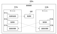
図6は、本発明の第1の実施形態の変形例に係る通信装置600qの構成を示す概略ブロック図である。図6に示されるように、通信装置600qは、デバイス610aと、デバイス610bと、電源部640とを含んで構成される。なお、図6において、破線の矢印は、制御信号が流れる制御信号線を表す。
[Configuration Example 2]
The functional configuration of the communication device 600q according to the second exemplary configuration will be described below.
Fig. 6 is a schematic block diagram showing a configuration of a communication device 600q according to a modified example of the first embodiment of the present invention. As shown in Fig. 6, the communication device 600q includes a
デバイス610aは、指揮系統部611aと、監視部612aと、通信処理部613aとを含んで構成される。また、デバイス610bは、監視部612bと、通信処理部613bとを含んで構成される。
このように、構成例2に係る通信装置600pでは、デバイス610aは指揮系統部を備えるが、デバイス610bは指揮系統部を備えない構成である。
The
In this manner, in the
デバイス610aの指揮系統部611aは、電源部640へ電源リセット指示を出力することにより、電源部640に対して通信装置600q全体の電源リセットを行わせることができる。
デバイス610bの監視部612bは、デバイス610aへリセット指示を出力することにより、デバイス610aに対して当該デバイス610aのリセットを行わせることができる。
The chain of
The
デバイス610aの監視部612aは、デバイス610bの通信処理部613bにおいてエラーが生じたことを検出することができる。監視部612aが、通信処理部613bにおいてエラーが生じたことを検出した場合、デバイス610aの指揮系統部611aは、電源部640へ電源リセット指示を出力する。The
デバイス610bの監視部612bは、デバイス610aの通信処理部613aにおいてエラーが生じたことを検出することができる。監視部612bは、通信処理部613aにおいてエラーが生じたことを検出した場合、デバイス610aへリセット指示を出力する。The
このように、構成例2に係る通信装置600pは、一方のデバイスが他方のデバイスの通信処理部でエラーが生じたことを検出した場合において、一方のデバイスが指揮系統部を備えているならば電源部640に電源リセットを行わせ、一方のデバイスが指揮系統部を備えていないならば他方のデバイスをリセットさせる構成である。In this way, the
[構成例3]
以下、構成例3に係る通信装置600rの機能構成について説明する。
図7は、本発明の第1の実施形態の変形例に係る通信装置600rの構成を示す概略ブロック図である。図7に示されるように、通信装置600rは、デバイス610aと、デバイス610bと、デバイス610cと、電源部640とを含んで構成される。なお、図7において、破線の矢印は、制御信号が流れる制御信号線を表す。
[Configuration Example 3]
The functional configuration of the
Fig. 7 is a schematic block diagram showing the configuration of a
デバイス610aは、指揮系統部611aと、監視部612aと、通信処理部613aとを含んで構成される。また、デバイス610bは、指揮系統部611bと、監視部612bと、通信処理部613bとを含んで構成される。また、デバイス610cは、監視部612cと、通信処理部613cとを含んで構成される。
このように、構成例3に係る通信装置600rでは、デバイス610a及びデバイス610bは指揮系統部を備えるが、デバイス610cは指揮系統部を備えない構成である。
The
In this manner, in the
デバイス610aの指揮系統部611a及びデバイス610bの指揮系統部611bは、電源部640へ電源リセット指示を出力することにより、電源部640に対して通信装置600p全体の電源リセットを行わせることができる。The command and
デバイス610cの監視部612cは、デバイス610aへリセット指示を出力することにより、デバイス610aに対して当該デバイス610aのリセットを行わせることができる。The
デバイス610aの監視部612aは、デバイス610bの通信処理部613b及びデバイス610cの通信処理部613cにおいてエラーが生じたことを検出することができる。監視部612aが、通信処理部613b又は通信処理部613bにおいてエラーが生じたことを検出した場合、デバイス610aの指揮系統部611aは、電源部640へ電源リセット指示を出力する。The
デバイス610bの監視部612bは、デバイス610aの通信処理部613aにおいてエラーが生じたことを検出することができる。監視部612bが、通信処理部613aにおいてエラーが生じたことを検出した場合、デバイス610bの指揮系統部611bは、電源部640へ電源リセット指示を出力する。The
デバイス610cの監視部612cは、デバイス610aの通信処理部613aにおいてエラーが生じたことを検出することができる。監視部612bは、通信処理部613aにおいてエラーが生じたことを検出した場合、デバイス610aへリセット指示を出力する。The
このように、構成例3に係る通信装置600rは、一方のデバイスが他方のデバイスの通信処理部でエラーが生じたことを検出した場合において、一方のデバイスが指揮系統部を備えているならば電源部640に電源リセットを行わせ、一方のデバイスが指揮系統部を備えていないならば他方のデバイスをリセットさせる構成である。In this way, the
<第2の実施形態>
以下、本発明の第2の実施形態について、図面を参照しながら説明する。なお、以下に説明する第2の実施形態における、通信システム1の全体構成図、及びONU100の機能構成を示す概略ブロック図は、それぞれ第1の実施形態と同様(すなわち、それぞれ図1及び図2と同様)であるため、説明を省略する。
Second Embodiment
The second embodiment of the present invention will be described below with reference to the drawings. Note that the overall configuration diagram of the
[デバイスの動作]
図8は、本発明の第2の実施形態に係るデバイス110の動作を示すフローチャートである。図8に示されるフローチャートは、ONU100において、エラーが生じた場合に開始する。なお、ここでいうエラーとは、他方のデバイス110で生じたエラーだけでなく、自己のデバイス110で生じたエラー、及びONU100内のその他の部材(デバイス110以外の部材)で生じたエラーを含んでいてもよい。
[Device Operation]
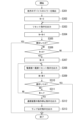
Fig. 8 is a flowchart showing the operation of the device 110 according to the second embodiment of the present invention. The flowchart shown in Fig. 8 starts when an error occurs in the
制御部/装置監視部112は、電源リセット指示を出力した回数をカウントするカウンターを示す変数Mの値に0を代入することにより、変数Mを初期化する(ステップS201)。なお、図8のフローチャートのステップS201及びステップS205に示される左向きの矢印は、右側の値を左側の変数に代入する動作を意味する。変数Mの値は、例えば、制御部/装置監視部112が備える記憶媒体(不図示)に一時記憶される。ここでいう記憶媒体とは、例えばCPUに搭載されたキャッシュメモリ等である。The control unit/device monitoring unit 112 initializes variable M, which indicates a counter that counts the number of times a power reset instruction has been output, by substituting 0 for the variable M (step S201). Note that the left-facing arrows shown in steps S201 and S205 of the flowchart in FIG. 8 indicate the operation of substituting the value on the right for the variable on the left. The value of variable M is temporarily stored, for example, in a storage medium (not shown) provided in the control unit/device monitoring unit 112. The storage medium here is, for example, a cache memory mounted on the CPU.
次に、デバイス110の制御部/装置監視部112は、自己の通信装置(ONU100)において生じたエラーを検出する(ステップS202)。前述の通り、ここでいうエラーとは、例えばデバイス110の暴走又は動作停止等を生じさせるようなエラーである。Next, the control unit/device monitoring unit 112 of the device 110 detects an error that has occurred in its own communication device (ONU 100) (step S202). As mentioned above, the error here refers to an error that may cause the device 110 to run out of control or stop operating, for example.
制御部/装置監視部112は、変数Mの値が所定値j未満であるか否かについての判定を行う(ステップS203)。なお、所定値jとは、電源リセット処理の最大試行回数を示す値である。所定値jは、例えば運用保守担当者等によって予め定められる値である。The control unit/device monitoring unit 112 determines whether the value of the variable M is less than a predetermined value j (step S203). The predetermined value j is a value indicating the maximum number of attempts to perform a power reset process. The predetermined value j is a value that is determined in advance, for example, by an operation and maintenance staff member.
変数Mの値が所定値j未満である場合(ステップS203・Yes)、制御部/装置監視部112は、制御信号線を介して、他方のデバイス110へのリセット指示の出力、又は、電源部140への電源リセット指示を出力を行う(ステップS204)。なお、制御部/装置監視部112が、他方のデバイス110へのリセット指示の出力、又は、電源部140への電源リセット指示を行うための動作は、例えば前述の図4に示されるフローチャートに従って行われる。次に、制御部/装置監視部112は、変数Mの値に1を加算する(ステップS205)。If the value of variable M is less than the predetermined value j (step S203: Yes), the control unit/device monitoring unit 112 outputs a reset instruction to the other device 110 or outputs a power reset instruction to the
次に、制御部/装置監視部112が、他方のデバイス110におけるリセット処理、又は、電源部140による電源リセット処理によりONU100が復旧したことを検出した場合(ステップS206・Yes)、図8のフローチャートが示すデバイス110の動作が終了する。一方、制御部/装置監視部112は、ONU100が復旧していないことを検出した場合(ステップS206・No)、前述のステップS203以降の動作を繰り返す。Next, if the control unit/device monitoring unit 112 detects that the
一方、変数Mの値が所定値jに達した場合(ステップS203・No)、制御部/装置監視部112は、自己の通信装置(ONU100)の動作停止指示を出力する(ステップS207)。On the other hand, if the value of variable M reaches the predetermined value j (step S203, No), the control unit/device monitoring unit 112 outputs an instruction to stop operation of its own communication device (ONU 100) (step S207).
なお、ONU100の動作を停止させる方法としては、任意の方法を用いることができる。例えば、制御部/装置監視部112は、ONU100全体への電力供給を停止させる指示である動作停止指示を制御信号線を介して電源部140へ出力することにより、ONU100の動作を停止させるようにしてもよい。Any method can be used to stop the operation of
次に、制御部/装置監視部112は、ONU100に備えられたランプ(不図示)を点灯させる指示を示す点灯指示を出力する(ステップS208)。以上で、図8のフローチャートが示すデバイス110の動作が終了する。Next, the control unit/device monitoring unit 112 outputs a turn-on instruction to turn on a lamp (not shown) provided in the ONU 100 (step S208). This completes the operation of the device 110 shown in the flowchart of FIG. 8.
なお、ランプを点灯させる方法としては、任意の方法を用いることができる。例えば、制御部/装置監視部112は、制御信号線を介して電源部140へ点灯指示を出力することにより電源部140からランプへの電力供給を開始させ、点灯させる。Any method can be used to light the lamp. For example, the control unit/device monitoring unit 112 outputs a lighting instruction to the
このように、ランプが点灯することにより、ユーザ又は運用保守担当者等は、ONU100が動作停止状態(異常状態)であることを認識することができる。ユーザ又は運用保守担当者等は、ONU100が動作停止状態であることを認識すると、手動によりONU100の動作状態を復旧させる。例えば、ユーザ又は運用保守担当者等は、ONU100が備える電源プラグ(不図示)をコンセント(不図示)に対して抜き差しすることにより、ONU100の動作状態を復旧させる。In this way, by the lamp being lit, a user or an operation and maintenance person can recognize that
なお、ユーザ又は運用保守担当者等に対してONU100が動作停止状態であることを通知することができる方法であるならば、ランプを点灯させる方法以外の方法が用いられてもよい。例えば、制御部/装置監視部112は、ONU100に備えられたスピーカ(不図示)を用いて、音声によりユーザ又は運用保守担当者等に対して通知するようにしてもよい。または、例えば、制御部/装置監視部112は、自己の通信装置(ONU100)又は外部装置に備えられた、例えば液晶ディスプレイ(LCD)等の表示装置(不図示)に、ONU100が動作停止状態であること示す情報を表示させるようにしてもよい。Note that any method other than turning on a lamp may be used as long as it can notify a user or an operation and maintenance person that
以上説明したように、第2の実施形態に係るONU100(通信装置)は、自己の通信装置の監視を行う。そして、ONU100は、自己の通信装置において例えば暴走又は動作停止等を生じさせるようなエラーが生じた場合に、自己の通信装置全体への電力の供給をリセットする電源リセットを実行させる。それでもなお、自己の通信装置が復旧しない場合、ONU100は、繰り返し電源リセットを実行させる。所定の回数に達するまで電源リセットを試行してもなお復旧しない場合には、ONU100は、自己の通信装置の動作を停止させる。そして、ONU100は、自己の通信装置が動作停止状態であることをユーザ又は運用保守担当者等に認識させるため、ランプを点灯させる。これにより、ONU100は、手動による自己の通信装置の復旧を促すことができる。ONU100は、ユーザ又は運用保守担当者等により手動で自己の通信装置の復旧がなされるまで待機する。As described above, the ONU 100 (communication device) according to the second embodiment monitors its own communication device. If an error occurs in its own communication device, such as a runaway or a stop in operation, the
以上のような構成を備えることによって、第2の実施形態に係るONU100は、自己の通信装置においてエラーが生じた場合に、自律的に自己の通信装置の復旧を試みることができる。ONU100は、例えば、電源リセット(又はリコンフィグレーション)によって復旧可能なエラーを検出した場合には、自律的に自己の通信装置をリセットさせ復旧させることができる。これにより、第2の実施形態に係るONU100によれば、人手による復旧作業が発生する頻度が低減されるため、自己の通信装置で生じたエラーに対処可能な通信装置の運用コストが削減される。
By being provided with the above-described configuration, the
なお、第2の実施形態によれば、例えば、宇宙線由来の中性子線が引き起こすソフトエラーへの耐性の向上も見込める。 In addition, according to the second embodiment, it is also expected that resistance to soft errors caused by neutron rays originating from cosmic rays can be improved.
なお、第2の実施形態では、デバイス110の制御部/装置監視部112は、ONU100で生じたエラーを検出した場合、まず、ONU100全体の電源リセットを指示し、それでも自己の通信装置が復旧しない場合には所定の回数に達するまで、繰り返し電源リセットを指示する。所定の回数に達してもなお復旧しない場合には、制御部/装置監視部112は、ONU100の動作停止させる。そして、制御部/装置監視部112は、ONU100に備えられたランプを点灯させる構成である。但し、このような構成に限られるものではなく、制御部/装置監視部112が前者の処理のみ又は後者の処理のみを行う構成であってもよい。すなわち、例えば、制御部/装置監視部112は、電源リセットの試行回数が所定の回数に達してもなお自己の通信装置が復旧しない場合には、自己の通信装置の動作停止させることだけを行うようにしてもよい(すなわち、ランプの点灯等による通知は行われない構成であってもよい)。又は、例えば、制御部/装置監視部112は、ONU100全体の電源リセットを指示しても自己の通信装置が復旧しない場合には、電源リセットの指示を繰り返し行うことなくランプを点灯させるようにしてもよい。In the second embodiment, when the control unit/device monitoring unit 112 of the device 110 detects an error occurring in the
<第2の実施形態の変形例>
以下、本発明の第2の実施形態の変形例について、図面を参照しながら説明する。なお、以下に説明する第2の実施形態の変形例における、通信システム1の全体構成図、及びONU100の機能構成を示す概略ブロック図は、それぞれ第1の実施形態と同様(すなわち、それぞれ図1及び図2と同様)であるため、説明を省略する。
<Modification of the second embodiment>
A modified example of the second embodiment of the present invention will be described below with reference to the drawings. Note that the overall configuration diagram of the
前述の第2の実施形態では、ONU100は、自己の通信装置で生じたエラーを検出した場合、まずは自己の通信装置全体への電力の供給をリセットする電源リセットを試み、それでもなお自己の通信装置が復旧しない場合には自己の通信装置の動作を停止させる構成であった。これに対し、以下に説明する第2の実施形態の変形例では、ONU100のデバイス110は、当該ONU100が備える他方のデバイス110で生じたエラーを検出した場合、まずはエラーが生じた他方のデバイス110のリセットを試みる。それでもなおデバイス110が復旧しない場合には、デバイス110は、電源リセットを試みる。そして、それでもなおデバイス110が復旧しない場合、デバイス110は、自己の通信装置の動作を停止させる構成である。In the second embodiment described above, when an error occurs in the
[デバイスの動作]
図9は、本発明の第2の実施形態の変形例に係るデバイス110の動作を示すフローチャートである。図9に示されるフローチャートは、他方のデバイス110においてエラーが生じた場合に開始する。なお、以下の説明では、例としてデバイス110aの動作を説明するが、デバイス110bの動作も同様である。
[Device Operation]
Fig. 9 is a flowchart showing the operation of the device 110 according to the modified example of the second embodiment of the present invention. The flowchart shown in Fig. 9 starts when an error occurs in the other device 110. Note that in the following description, the operation of the
デバイス110aの制御部/装置監視部112aは、他方のデバイス110(デバイス110b)において生じたエラーを検出する(ステップS301)。前述の通り、ここでいうエラーとは、例えばデバイス110の暴走又は動作停止等を生じさせるエラーである。次に、制御部/装置監視部112aは、リセット指示を出力した回数をカウントするカウンターを示す変数Nの値に0を代入することにより、変数Nを初期化する(ステップS302)。なお、図9のフローチャートのステップS302、ステップS304、ステップS307、及びステップS309に示される左向きの矢印は、右側の値を左側の変数に代入する動作を意味する。変数Nの値は、例えば、制御部/装置監視部112aが備える記憶媒体(不図示)に一時記憶される。The control unit/
次に、制御部/装置監視部112aは、制御信号線を介してデバイス110bへリセット指示を出力する(ステップS303)。次に、制御部/装置監視部112aは、変数Nの値に1を加算する(ステップS304)。Next, the control unit/
次に、制御部/装置監視部112aが、リセットによりデバイス110bが復旧したことを検出した場合(ステップS305・Yes)、図9のフローチャートが示すデバイス110aの動作が終了する。一方、制御部/装置監視部112aは、デバイス110bが復旧していないことを検出した場合(ステップS305・No)、変数Nの値が所定値k未満であるか否かについての判定を行う(ステップS306)。なお、所定値kとは、デバイス110のリセット処理の最大試行回数を示す値である。所定値kは、例えば運用保守担当者等によって予め定められる値である。Next, if the control unit/
変数Nの値が所定値k未満である場合(ステップS306・No)、制御部/装置監視部112aは、前述のステップS303以降の動作を繰り返す。一方、変数Nの値が所定値kに達した場合(ステップS306・Yes)、制御部/装置監視部112aは、ステップS307以降の動作を行う。なお、図9に示されるステップS307以降の動作は、図8に示されるステップS202以降の動作と同様であるため、説明を省略する。If the value of the variable N is less than the predetermined value k (step S306, No), the control unit/
なお、ステップS311における変数M及び所定値jの値として、前述のステップS306で用いられる変数N及び所定値kの値がそれぞれ用いられるような構成であってもよい。すなわち、デバイス110対するリセット処理の最大試行回数と、ONU100全体に対する電源部140による電源リセット処理の最大試行回数とは、それぞれ共通の変数及び共通の所定値が用いられてもよい。In addition, the values of the variable M and the predetermined value j in step S311 may be the same as the values of the variable N and the predetermined value k used in step S306 described above. In other words, the maximum number of attempts to perform a reset process on the device 110 and the maximum number of attempts to perform a power reset process by the
以上説明したように、第2の実施形態の変形例に係るONU100(通信装置)のデバイス110は、自己の通信装置の監視を行う。そして、デバイス110は、他方のデバイス110において暴走又は動作停止等を生じさせるようなエラーが生じた場合に、他方のデバイス110の動作状態をリセットさせる。それでもなお、他方のデバイス110が復旧しない場合、デバイス110は、繰り返し他方のデバイス110の動作状態をリセットさせる。所定の回数に達するまでリセットを試行してもなお復旧しない場合には、デバイス110は、自己の通信装置全体の電源をリセットする電源リセットを実行させる。それでもなお、自己の通信装置が復旧しない場合、デバイス110は、繰り返し電源リセットを実行させる。所定の回数に達するまで電源リセットを試行してもなお復旧しない場合には、デバイス110は、自己の通信装置の動作を停止させる。そして、デバイス110は、自己の通信装置が動作停止状態であることをユーザ又は運用保守担当者等に認識させるため、ランプを点灯させる。ONU100は、ユーザ又は運用保守担当者等により手動で自己の通信装置の復旧がなされるまで待機する。As described above, the device 110 of the ONU 100 (communication device) according to the modified example of the second embodiment monitors its own communication device. Then, when an error occurs in the other device 110 that causes the other device 110 to go out of control or stop working, the device 110 resets the operation state of the other device 110. If the other device 110 still does not recover, the device 110 repeatedly resets the operation state of the other device 110. If the device still does not recover after attempting the reset a predetermined number of times, the device 110 executes a power reset to reset the power of the entire communication device. If the device still does not recover, the device 110 repeatedly executes a power reset. If the device still does not recover after attempting the power reset a predetermined number of times, the device 110 stops the operation of the communication device. Then, the device 110 turns on a lamp to let the user or the operation and maintenance staff know that the communication device is in a stopped state. The
以上のような構成を備えることによって、第2の実施形態の変形例に係るONU100は、自己の通信装置においてエラーが生じた場合に、自律的に自己の通信装置の復旧を試みることができる。ONU100は、例えば、電源リセット(又はリコンフィグレーション)によって復旧可能なエラーを検出した場合には、自律的に自己の通信装置をリセットさせ復旧させることができる。By being provided with the above-described configuration, the
なお、前述の各実施形態では、一例として、ONU100が自己の通信装置で生じるエラーを検出し復旧を行う構成であるものとした。但し、本発明を適用することできる装置はONU100に限られるものではなく、他の装置においても適用可能である。ここでいう他の装置とは、例えば、OLT300、10G-EPON以外の通信システムにおける通信装置、及び通信装置以外の装置である。
In each of the above-mentioned embodiments, as an example,
上述した実施形態におけるONU100の一部又は全部をコンピュータで実現するようにしてもよい。その場合、この機能を実現するためのプログラムをコンピュータ読み取り可能な記録媒体に記録して、この記録媒体に記録されたプログラムをコンピュータシステムに読み込ませ、実行することによって実現してもよい。なお、ここでいう「コンピュータシステム」とは、OSや周辺機器のハードウェアを含むものとする。また、「コンピュータ読み取り可能な記録媒体」とは、フレキシブルディスク、光磁気ディスク、ROM、CD-ROM等の可搬媒体、コンピュータシステムに内蔵されるハードディスク等の記録装置のことをいう。さらに「コンピュータ読み取り可能な記録媒体」とは、インターネット等のネットワークや電話回線等の通信回線を介してプログラムを送信する場合の通信線のように、短時間の間、動的にプログラムを保持するもの、その場合のサーバやクライアントとなるコンピュータシステム内部の揮発性メモリのように、一定時間プログラムを保持しているものを含んでもよい。また上記プログラムは、前述した機能の一部を実現するためのものであってもよく、さらに前述した機能をコンピュータシステムにすでに記録されているプログラムとの組み合わせで実現できるものであってもよく、FPGA(Field Programmable Gate Array)等のプログラマブルロジックデバイスを用いて実現されるものであってもよい。
A part or all of the
以上、この発明の実施形態について図面を参照して詳述してきたが、具体的な構成はこの実施形態に限られるものではなく、この発明の要旨を逸脱しない範囲の設計等も含まれる。 Although an embodiment of the present invention has been described in detail above with reference to the drawings, the specific configuration is not limited to this embodiment and also includes designs that do not deviate from the gist of the present invention.
1・・・通信システム、100・・・ONU、110(110a,110b)・・・デバイス、111(111a,111b)・・・主信号処理部、112(112a,112b)・・・制御部/装置監視部、120・・・光受電部、130・・・UNI、140・・・電源部、200・・・ユーザ端末、300・・・OLT、400・・・光スプリッタ 1: communication system, 100: ONU, 110 (110a, 110b): device, 111 (111a, 111b): main signal processing unit, 112 (112a, 112b): control unit/device monitoring unit, 120: optical receiving unit, 130: UNI, 140: power supply unit, 200: user terminal, 300: OLT, 400: optical splitter
Claims (6)
を備え、
前記デバイスの少なくとも1つは、自己の通信装置への電力の供給をリセットさせる指揮系統部
をさらに備え、
各々の前記デバイスは、前記複数のデバイスに含まれる少なくとも1つの他のデバイスを監視して、前記他のデバイスにおいて生じたエラーを検出する監視部
を備え、
各々の前記デバイスは、前記複数のデバイスに含まれる少なくとも1つの他のデバイスによって監視され、
前記デバイスの少なくとも1つが備える監視部は、前記他のデバイスにおいて生じたエラーを検出した場合、前記他のデバイスの動作状態をリセットさせる
通信装置。 With multiple devices,
At least one of the devices includes a chain of command section that resets the power supply to its communication device.
Further equipped with
each of the devices includes a monitoring unit that monitors at least one other device included in the plurality of devices to detect an error occurring in the other device;
each of said devices being monitored by at least one other device in said plurality of devices;
A communication apparatus, wherein a monitoring unit included in at least one of the devices resets an operation state of the other device when an error occurring in the other device is detected.
前記指揮系統部は自己の通信装置への電力の供給をリセットさせる
請求項1に記載の通信装置。 When the monitoring unit of at least one of the devices detects an error occurring in the other device,
The communication device according to claim 1 , wherein the command system unit resets the power supply to the communication device itself.
請求項2に記載の通信装置。 The communication device according to claim 2 , wherein, when the operational state of the communication device itself is not restored by resetting the operational state of the other device, the command and control unit resets the supply of power to the communication device itself.
請求項2に記載の通信装置。 The communication device according to claim 2 , wherein, if the operational state of the communication device itself is not restored by resetting the operational state of the other device, the device stops the operation of the communication device itself.
請求項1から請求項4のうちいずれか一項に記載の通信装置。 The communication device according to claim 1 , wherein the communication device is a terminal device of an optical line.
自己の通信装置への電力の供給をリセットさせるステップと、
前記複数のデバイスに含まれる少なくとも1つの他のデバイスを監視して、前記他のデバイスにおいて生じたエラーを検出するステップと、
前記他のデバイスにおいて生じたエラーを検出した場合、前記他のデバイスの動作状態をリセットさせるステップと、
を有するエラー検出方法。 1. A method for detecting an error in a communication apparatus comprising a plurality of devices, each of which is monitored by at least one other device included in the plurality of devices, comprising:
resetting the power supply to the communication device;
monitoring at least one other device included in the plurality of devices to detect an error occurring in the other device;
resetting an operation state of the other device when an error occurring in the other device is detected;
The error detection method includes:
Applications Claiming Priority (1)
| Application Number | Priority Date | Filing Date | Title |
|---|---|---|---|
| PCT/JP2020/005494 WO2021161441A1 (en) | 2020-02-13 | 2020-02-13 | Communication apparatus and error detection method |
Publications (2)
| Publication Number | Publication Date |
|---|---|
| JPWO2021161441A1 JPWO2021161441A1 (en) | 2021-08-19 |
| JP7477780B2 true JP7477780B2 (en) | 2024-05-02 |
Family
ID=77291484
Family Applications (1)
| Application Number | Title | Priority Date | Filing Date |
|---|---|---|---|
| JP2021577782A Active JP7477780B2 (en) | 2020-02-13 | 2020-02-13 | Communication device and error detection method |
Country Status (3)
| Country | Link |
|---|---|
| US (1) | US11863230B2 (en) |
| JP (1) | JP7477780B2 (en) |
| WO (1) | WO2021161441A1 (en) |
Citations (7)
| Publication number | Priority date | Publication date | Assignee | Title |
|---|---|---|---|---|
| JP2005222379A (en) | 2004-02-06 | 2005-08-18 | Hitachi Ltd | Disk-array device and control method for avoiding failure thereof |
| JP2008061091A (en) | 2006-09-01 | 2008-03-13 | Hitachi Communication Technologies Ltd | Path setting method and node device |
| KR101296515B1 (en) | 2012-04-10 | 2013-09-16 | 에스케이텔레시스 주식회사 | Optical repeater with remote recovery function and remote recovery method of optical repeater |
| JP2014135679A (en) | 2013-01-11 | 2014-07-24 | Mitsubishi Electric Corp | Terminal-side communication device, station-side device and communication failure restoration method |
| JP2014207593A (en) | 2013-04-15 | 2014-10-30 | 西日本電信電話株式会社 | Remote power restart device for optical line device |
| JP2017158088A (en) | 2016-03-03 | 2017-09-07 | 西日本電信電話株式会社 | Subscriber line termination device and recovery method |
| JP2018037947A (en) | 2016-09-01 | 2018-03-08 | 日本電信電話株式会社 | Geomagnetic information transfer device |
Family Cites Families (21)
| Publication number | Priority date | Publication date | Assignee | Title |
|---|---|---|---|---|
| JP2004303271A (en) | 1999-05-11 | 2004-10-28 | Sharp Corp | One-chip microcomputer, its control method, and ic card using the same |
| JP3576457B2 (en) | 1999-05-11 | 2004-10-13 | シャープ株式会社 | One-chip microcomputer, control method thereof, and IC card using the same |
| US7317681B1 (en) * | 2002-01-11 | 2008-01-08 | Cisco Systems O.I.A. (1988)Ltd. | Redundancy for dual optical ring concentrator |
| US20050283641A1 (en) * | 2004-05-21 | 2005-12-22 | International Business Machines Corporation | Apparatus, system, and method for verified fencing of a rogue node within a cluster |
| US20060029389A1 (en) * | 2004-08-05 | 2006-02-09 | Optical Solutions, Inc. | Optical network terminal with low power hibernation |
| GB2421671A (en) * | 2004-12-22 | 2006-06-28 | Marconi Comm Gmbh | A node selects a source of timing information using network topology and the timing status of network nodes |
| WO2007010518A1 (en) * | 2005-07-18 | 2007-01-25 | Passave Ltd. | Method and system for passive optical network diagnostics |
| US7710864B2 (en) * | 2006-01-16 | 2010-05-04 | Cisco Technology, Inc. | Recovery mechanism for 10 GE optical transport network wavelength division multiplexing ring |
| JP5060057B2 (en) * | 2006-03-08 | 2012-10-31 | 富士通株式会社 | Communication line monitoring system, relay device, and communication line monitoring method |
| US7539359B2 (en) * | 2007-04-02 | 2009-05-26 | Ciena Corporation | Systems and methods for chirp control of a dual arm Z-modulator to minimize dispersion effect of fiber plant |
| US20090285576A1 (en) * | 2008-05-16 | 2009-11-19 | Tellabs Vienna, Inc. | Method and apparatus for feedback/configuration of optical network terminal (ONT) anomalies to/from a central location |
| US8488962B2 (en) * | 2010-05-03 | 2013-07-16 | Verizon Patent And Licensing Inc. | Bit error generation system for optical networks |
| CN102377479B (en) * | 2010-08-11 | 2015-01-21 | 华为技术有限公司 | Data synchronization method and system and optical network units |
| JP6056494B2 (en) * | 2013-01-17 | 2017-01-11 | 富士通株式会社 | Determination device, determination method, and determination program |
| US10033459B2 (en) * | 2013-02-15 | 2018-07-24 | Lantiq Deutschland Gmbh | System, method and apparatus for a rogue optics network unit |
| CN105337657B (en) * | 2014-08-15 | 2018-08-24 | 上海诺基亚贝尔股份有限公司 | Method and device in passive optical network for determining rogue ONU |
| US9800327B2 (en) * | 2014-11-20 | 2017-10-24 | At&T Intellectual Property I, L.P. | Apparatus for controlling operations of a communication device and methods thereof |
| US9565083B2 (en) * | 2014-11-21 | 2017-02-07 | Ciena Corporation | In-band signaling for network protection switching |
| CN109586864B (en) * | 2017-09-28 | 2021-01-15 | 华为技术有限公司 | Data transmission method, device and system |
| JP7035877B2 (en) * | 2018-07-20 | 2022-03-15 | 富士通株式会社 | Transmission equipment |
| JP2020174319A (en) * | 2019-04-12 | 2020-10-22 | 富士通株式会社 | Measuring device, transmission device, and network system |
-
2020
- 2020-02-13 JP JP2021577782A patent/JP7477780B2/en active Active
- 2020-02-13 US US17/798,300 patent/US11863230B2/en active Active
- 2020-02-13 WO PCT/JP2020/005494 patent/WO2021161441A1/en active Application Filing
Patent Citations (7)
| Publication number | Priority date | Publication date | Assignee | Title |
|---|---|---|---|---|
| JP2005222379A (en) | 2004-02-06 | 2005-08-18 | Hitachi Ltd | Disk-array device and control method for avoiding failure thereof |
| JP2008061091A (en) | 2006-09-01 | 2008-03-13 | Hitachi Communication Technologies Ltd | Path setting method and node device |
| KR101296515B1 (en) | 2012-04-10 | 2013-09-16 | 에스케이텔레시스 주식회사 | Optical repeater with remote recovery function and remote recovery method of optical repeater |
| JP2014135679A (en) | 2013-01-11 | 2014-07-24 | Mitsubishi Electric Corp | Terminal-side communication device, station-side device and communication failure restoration method |
| JP2014207593A (en) | 2013-04-15 | 2014-10-30 | 西日本電信電話株式会社 | Remote power restart device for optical line device |
| JP2017158088A (en) | 2016-03-03 | 2017-09-07 | 西日本電信電話株式会社 | Subscriber line termination device and recovery method |
| JP2018037947A (en) | 2016-09-01 | 2018-03-08 | 日本電信電話株式会社 | Geomagnetic information transfer device |
Also Published As
| Publication number | Publication date |
|---|---|
| US20230070907A1 (en) | 2023-03-09 |
| WO2021161441A1 (en) | 2021-08-19 |
| US11863230B2 (en) | 2024-01-02 |
| JPWO2021161441A1 (en) | 2021-08-19 |
Similar Documents
| Publication | Publication Date | Title |
|---|---|---|
| US7536584B2 (en) | Fault-isolating SAS expander | |
| US7565567B2 (en) | Highly available computing platform | |
| EP2052326B1 (en) | Fault-isolating sas expander | |
| US6657534B1 (en) | Remote power control | |
| JP2007109238A (en) | System and method for logging recoverable error | |
| US8510578B2 (en) | Line-card disabling for power management | |
| US20200193023A1 (en) | System and method for detecting malicious software in nvme over fabrics devices | |
| US10275373B2 (en) | Hot swappable device and method | |
| JP2006309317A (en) | Storage system and its control method | |
| WO2010140189A1 (en) | Storage system and control methods for the same | |
| TW201911813A (en) | Network Switching System | |
| CN110370288B (en) | Robot safety control method, device, equipment and storage medium | |
| US20220171719A1 (en) | Storage system and method for switching working mode of storage system | |
| JP2008097605A (en) | Method and apparatus to internalize non-volatile data function for sector size conversion | |
| JP4655718B2 (en) | Computer system and control method thereof | |
| JP7477780B2 (en) | Communication device and error detection method | |
| US8917609B2 (en) | Line monitoring apparatus and line monitoring method | |
| JP7360063B2 (en) | Communication equipment and error handling methods | |
| JP2007334731A (en) | Usb equipment, host device and usb connection system | |
| CN110377238A (en) | A kind of storage system and its data transmission method, device and NVMe controller chassis | |
| US20110066921A1 (en) | System and Method for Responding to Error Detection | |
| JP2004013723A (en) | Device and method for fault recovery of information processing system adopted cluster configuration using shared memory | |
| JP7447059B2 (en) | Network equipment and network systems | |
| US11669399B2 (en) | System and method for fault identification and fault handling in a multiport power sourcing device | |
| TWM556046U (en) | Network switching control system |
Legal Events
| Date | Code | Title | Description |
|---|---|---|---|
| A621 | Written request for application examination |
Free format text: JAPANESE INTERMEDIATE CODE: A621 Effective date: 20220607 |
|
| A131 | Notification of reasons for refusal |
Free format text: JAPANESE INTERMEDIATE CODE: A131 Effective date: 20230411 |
|
| A521 | Request for written amendment filed |
Free format text: JAPANESE INTERMEDIATE CODE: A523 Effective date: 20230530 |
|
| A131 | Notification of reasons for refusal |
Free format text: JAPANESE INTERMEDIATE CODE: A131 Effective date: 20230829 |
|
| A521 | Request for written amendment filed |
Free format text: JAPANESE INTERMEDIATE CODE: A523 Effective date: 20231002 |
|
| A131 | Notification of reasons for refusal |
Free format text: JAPANESE INTERMEDIATE CODE: A131 Effective date: 20231222 |
|
| A521 | Request for written amendment filed |
Free format text: JAPANESE INTERMEDIATE CODE: A523 Effective date: 20240123 |
|
| TRDD | Decision of grant or rejection written | ||
| A01 | Written decision to grant a patent or to grant a registration (utility model) |
Free format text: JAPANESE INTERMEDIATE CODE: A01 Effective date: 20240319 |
|
| A61 | First payment of annual fees (during grant procedure) |
Free format text: JAPANESE INTERMEDIATE CODE: A61 Effective date: 20240401 |