JP7476412B2 - Vehicle crash test method - Google Patents
Vehicle crash test method Download PDFInfo
- Publication number
- JP7476412B2 JP7476412B2 JP2023132755A JP2023132755A JP7476412B2 JP 7476412 B2 JP7476412 B2 JP 7476412B2 JP 2023132755 A JP2023132755 A JP 2023132755A JP 2023132755 A JP2023132755 A JP 2023132755A JP 7476412 B2 JP7476412 B2 JP 7476412B2
- Authority
- JP
- Japan
- Prior art keywords
- target vehicle
- time
- vehicle
- collision
- speed
- Prior art date
- Legal status (The legal status is an assumption and is not a legal conclusion. Google has not performed a legal analysis and makes no representation as to the accuracy of the status listed.)
- Active
Links
- 238000010998 test method Methods 0.000 title claims description 53
- 230000001133 acceleration Effects 0.000 claims description 17
- 238000012360 testing method Methods 0.000 claims description 14
- 239000011159 matrix material Substances 0.000 claims description 9
- 238000000034 method Methods 0.000 claims description 5
- 230000004044 response Effects 0.000 claims description 3
- 238000006073 displacement reaction Methods 0.000 claims description 2
- 238000012546 transfer Methods 0.000 claims description 2
- 238000012937 correction Methods 0.000 description 4
- 238000005070 sampling Methods 0.000 description 4
- 238000010586 diagram Methods 0.000 description 2
- 230000000694 effects Effects 0.000 description 2
- 238000012986 modification Methods 0.000 description 2
- 230000004048 modification Effects 0.000 description 2
- 238000009795 derivation Methods 0.000 description 1
- 230000006870 function Effects 0.000 description 1
Images


Classifications
-
- G—PHYSICS
- G07—CHECKING-DEVICES
- G07C—TIME OR ATTENDANCE REGISTERS; REGISTERING OR INDICATING THE WORKING OF MACHINES; GENERATING RANDOM NUMBERS; VOTING OR LOTTERY APPARATUS; ARRANGEMENTS, SYSTEMS OR APPARATUS FOR CHECKING NOT PROVIDED FOR ELSEWHERE
- G07C5/00—Registering or indicating the working of vehicles
- G07C5/02—Registering or indicating driving, working, idle, or waiting time only
- G07C5/04—Registering or indicating driving, working, idle, or waiting time only using counting means or digital clocks
-
- G—PHYSICS
- G01—MEASURING; TESTING
- G01M—TESTING STATIC OR DYNAMIC BALANCE OF MACHINES OR STRUCTURES; TESTING OF STRUCTURES OR APPARATUS, NOT OTHERWISE PROVIDED FOR
- G01M17/00—Testing of vehicles
- G01M17/007—Wheeled or endless-tracked vehicles
-
- G—PHYSICS
- G07—CHECKING-DEVICES
- G07C—TIME OR ATTENDANCE REGISTERS; REGISTERING OR INDICATING THE WORKING OF MACHINES; GENERATING RANDOM NUMBERS; VOTING OR LOTTERY APPARATUS; ARRANGEMENTS, SYSTEMS OR APPARATUS FOR CHECKING NOT PROVIDED FOR ELSEWHERE
- G07C5/00—Registering or indicating the working of vehicles
- G07C5/08—Registering or indicating performance data other than driving, working, idle, or waiting time, with or without registering driving, working, idle or waiting time
- G07C5/0841—Registering performance data
- G07C5/085—Registering performance data using electronic data carriers
-
- G—PHYSICS
- G08—SIGNALLING
- G08G—TRAFFIC CONTROL SYSTEMS
- G08G1/00—Traffic control systems for road vehicles
- G08G1/16—Anti-collision systems
- G08G1/166—Anti-collision systems for active traffic, e.g. moving vehicles, pedestrians, bikes
Description
本発明は、車両衝突試験方法に関し、より詳しくは、先行車を追従する追従車の衝突試験に関し、衝突試験方法を生成し、生成された衝突試験方法によってより正確でかつ安全な車両試験方法を開発するための車両衝突試験方法に関する。
本出願は、国土交通部・国土交通科学技術振興院の支援により行われた(課題番号21AMDP-C160637-01)。
The present invention relates to a vehicle crash test method, and more particularly to a crash test of a following vehicle following a leading vehicle, and relates to a vehicle crash test method for generating a crash test method and developing a more accurate and safer vehicle test method using the generated crash test method.
This application was supported by the Ministry of Land, Infrastructure and Transport, Land, Infrastructure and Transport Science and Technology Agency (Issue No. 21AMDP-C160637-01).
最近、運転者の不注意で発生する事故を防止するために運転者に車両の走行情報を伝達するとともに、運転者の便宜のための自律走行のために多様な運転支援システム(DAS:Driver Assistance Systems)が開発されている。 Recently, various driver assistance systems (DAS) have been developed to provide vehicle driving information to drivers to prevent accidents caused by driver negligence, and to enable autonomous driving for the convenience of drivers.
一例として、車両のバンパーに装着された電磁石を通じて他の車両との距離を獲得し、獲得された他の車両との距離が一定距離以内であれば、衝突状況と判断して電磁石に電源を供給することで磁力を発生させ、これにより車両が衝突状況時に自動で制動されるようにする技術が挙げられる。 One example is a technology that uses an electromagnet attached to the vehicle's bumper to obtain the distance to another vehicle, and if the obtained distance is within a certain distance, it determines that a collision situation is occurring and supplies power to the electromagnet to generate magnetic force, thereby automatically braking the vehicle in the event of a collision.
また他の例として、車両に設けられて車両の周辺の映像を獲得し、獲得された映像を基盤で車両の走行を制御するビジョン技術が挙げられる。 Another example is vision technology that is installed in a vehicle to capture images of the vehicle's surroundings and control the vehicle's driving based on the captured images.
このような自律走行技術は、運転者の安全と密接した関連がある。例えば、自律走行技術を利用した先行車を追従する追従車は、先行車の停止または減速を、遅滞なく感知して衝突を未然に防止して適宜対応することができる技術は必須である。したがって、自律走行車両の衝突を備える、または衝突に対する安全度を測定するための試験が多様に開発されている。 Such autonomous driving technology is closely related to the safety of drivers. For example, a vehicle following a leading vehicle using autonomous driving technology must have the technology to promptly detect when the leading vehicle has stopped or slowed down and respond appropriately to prevent a collision. Therefore, various tests are being developed to prepare for the collision of autonomous vehicles or to measure safety against collisions.
このような衝突試験は、もっぱら自律走行の性能のみを試すものではなく、運転者の意図で車両が停止する場合にも車両の性能を試すことができる。それゆえ、車両の衝突に関連する多様な要因を考慮した試験状況(シナリオ)を選定及び開発して、開発された試験技法の正確性と有効性に対する検討が必要な実情である。 Such crash tests do not only test autonomous driving performance, but also test the vehicle's performance when the vehicle stops at the driver's discretion. Therefore, it is necessary to select and develop test situations (scenarios) that take into account various factors related to vehicle collisions, and to examine the accuracy and effectiveness of the developed test techniques.
そこで、本発明の技術的課題は、先行車を追従する追従車の衝突試験方法を提供することである。 The technical objective of the present invention is to provide a method for crash testing a vehicle following a preceding vehicle.
また、本発明の技術的課題は、車両衝突試験方法のあらゆる可能なシナリオを選定して、選定されたシナリオを適用した試験方法の正確性を高めることである。 The technical objective of the present invention is to select all possible scenarios for a vehicle crash test method and to increase the accuracy of the test method by applying the selected scenarios.
また、本発明の技術的課題は、車両衝突試験方法上のあらゆる可能なシナリオを選定して、選定されたシナリオを適用して各車両の衝突に対する安全度を測定することである。 The technical problem of the present invention is to select all possible scenarios for a vehicle crash test method and measure the crash safety of each vehicle by applying the selected scenarios.
前述した目的を達成するためになされた本発明の一態様によれば、ターゲット車両の速度及び目標加速度を設定する段階と、前記ターゲット車両の設定された速度及び目標加速度に対応して対象車両の速度及び加速度を観測する段階と、前記ターゲット車両の減速以後、第1の臨界時間超えの場合は、前記対象車両を減速させて、衝突余裕時間(TTC:Time to Collision)を算出する段階と、前記算出された衝突余裕時間が、第1の臨界時間よりも長い、第2の臨界時間未満であれば、前記対象車両の情報を保存する段階と、を含む、車両衝突試験方法を提供することができる。 According to one aspect of the present invention made to achieve the above-mentioned object, a vehicle collision test method can be provided, which includes the steps of: setting a speed and a target acceleration of a target vehicle; observing the speed and acceleration of the target vehicle corresponding to the set speed and target acceleration of the target vehicle; if the deceleration of the target vehicle exceeds a first critical time, decelerating the target vehicle and calculating a time to collision (TTC); and if the calculated time to collision is longer than the first critical time and less than a second critical time, storing information of the target vehicle.
また、前記算出された衝突余裕時間が、第1の臨界時間よりも長い、第2の臨界時間未満であれば、前記対象車両の情報を保存する段階は、前記ターゲット車両の速度を区間間隔で分けて設定する段階と、前記ターゲット車両の加速度を区間間隔で分けて設定する段階と、設定された前記ターゲット車両の速度に対する区間間隔と設定されたターゲット車両の加速度に対する区間間隔との組み合わせにより複数のシナリオを選定する段階と、複数のシナリオに対して算出された衝突余裕時間が第2の臨界時間未満の場合、選択シナリオとして選定する段階と、を含むことができる。 In addition, if the calculated collision time margin is less than a second critical time that is longer than the first critical time, the step of storing the information of the target vehicle may include the steps of setting the speed of the target vehicle divided by intervals, setting the acceleration of the target vehicle divided by intervals, selecting a plurality of scenarios by combining the intervals for the set speed of the target vehicle and the intervals for the set acceleration of the target vehicle, and selecting a scenario as a selected scenario if the collision time margin calculated for the plurality of scenarios is less than the second critical time.
また、複数のシナリオに対して算出された衝突余裕時間が第2の臨界時間未満の場合、選択シナリオとして選定する段階は、予め設定した時間間隔ごとに前記対象車両の衝突余裕時間を算出する段階と、算出された衝突余裕時間の中で最小衝突余裕時間を選択シナリオとして選定する段階と、を含むことができる。 In addition, when the collision margin times calculated for the multiple scenarios are less than the second critical time, the step of selecting the selected scenario may include a step of calculating the collision margin times of the target vehicle at preset time intervals, and a step of selecting the minimum collision margin time among the calculated collision margin times as the selected scenario.
また、算出された衝突余裕時間の中で最小衝突余裕時間を選択シナリオとして選定する段階は、前記最小衝突余裕時間が前記第2の臨界時間未満の場合、選択シナリオとして保存する段階と、前記最小衝突余裕時間が前記第2の臨界時間超過の場合、非選択シナリオとして保存する段階と、を含むことができる。 The step of selecting the minimum collision margin time from the calculated collision margin times as the selected scenario may include a step of saving the minimum collision margin time as the selected scenario if the minimum collision margin time is less than the second critical time, and a step of saving the minimum collision margin time as a non-selected scenario if the minimum collision margin time exceeds the second critical time.
また、前記第1の臨界時間は、前記対象車両の危険決定判断時間及びペダル切り替え(transfer)の機械的時間を考慮して設定されることができる。 The first critical time may be set taking into account the risk determination time of the target vehicle and the mechanical time of pedal transfer.
また、前記第1の臨界時間は、前記対象車両の速度が前記ターゲット車両の速度を同一に追従する走行状況下で算出されたことを特徴とすることができる。 The first critical time may be calculated under driving conditions in which the speed of the subject vehicle closely follows the speed of the target vehicle.
また、前記対象車両の速度が前記ターゲット車両の速度と異なる走行状況の場合には、前記第1の臨界時間が補正されることを特徴とすることができる。 In addition, when the driving conditions are such that the speed of the subject vehicle is different from the speed of the target vehicle, the first critical time is corrected.
また、前記最小衝突余裕時間が前記第2の臨界時間未満の場合、選択シナリオとして保存する段階は、前記最小衝突余裕時間が前記第2の臨界時間未満であり、前記対象車両が停止するか、前記対象車両と前記ターゲット車両の変位とが等しい場合に、前記対象車両の走行情報を保存する段階、をさらに含むことができる。 In addition, when the minimum collision time is less than the second critical time, the step of saving as a selected scenario may further include a step of saving driving information of the target vehicle when the minimum collision time is less than the second critical time and the target vehicle stops or the displacement of the target vehicle is equal to that of the target vehicle.
また、前記対象車両の走行情報を保存する段階は、前記対象車両の加速度、及び予め設定した時間間隔ごとに算出された衝突余裕時間を含む複数の変数のパラメータをマトリックス形態で保存されることができる。 In addition, the step of storing the driving information of the target vehicle may store parameters of a plurality of variables, including the acceleration of the target vehicle and the collision margin time calculated at each preset time interval, in a matrix form.
また、算出された衝突余裕時間のうち最小衝突余裕時間を選択シナリオとして選定する段階は、前記選択シナリオまたは前記非選択シナリオとして保存された対象車両の走行情報をマトリックス形態で保存する段階と、前記保存された対象車両の走行情報に基づいて前記対象車両の運転習慣を分析する段階と、をさらに含むことができる。 The step of selecting the minimum collision margin time from the calculated collision margin times as a selected scenario may further include the steps of storing the driving information of the target vehicle stored as the selected scenario or the non-selected scenario in a matrix form, and analyzing the driving habits of the target vehicle based on the stored driving information of the target vehicle.
本発明の実施形態に係る車両衝突試験方法によれば、先行車を追従する追従車の衝突試験の安全性を高めることができる。 The vehicle crash test method according to the embodiment of the present invention can improve the safety of crash tests of a following vehicle that follows a leading vehicle.
また、本発明の実施形態に係る車両衝突試験方法によれば、車両衝突試験方法のあらゆる可能なシナリオを選定し、選定されたシナリオを適用した試験方法の正確度を高めることができる。 In addition, according to the vehicle crash test method of the embodiment of the present invention, it is possible to select all possible scenarios for the vehicle crash test method and increase the accuracy of the test method by applying the selected scenarios.
また、本発明の実施形態に係る車両衝突試験方法によれば、車両衝突試験方法上のあらゆる可能なシナリオを選定し、選定されたシナリオを適用して各車両の衝突に対する安全度を測定することができる。 In addition, according to the vehicle crash test method of the embodiment of the present invention, all possible scenarios in the vehicle crash test method can be selected and the selected scenarios can be applied to measure the crash safety of each vehicle.
ただし、本発明の効果は、前記した効果に限定されるものではなく、本発明の思想及び領域から外れない範囲内で多様に拡張されることができる。 However, the effects of the present invention are not limited to the effects described above, and can be expanded in various ways without departing from the spirit and scope of the present invention.
以下、図面を参照して本発明の好ましい実施形態をより詳細に説明する。 Below, a preferred embodiment of the present invention will be described in more detail with reference to the drawings.
本発明は、多様な変更を加えることができ、いろいろな形態を有することができるところ、特定の実施形態を図面に例示して本文に詳細に説明する。しかし、これは本発明を特定の開示形態に対して限定しようとするものではなく、本発明の思想及び技術範囲に含まれるすべての変更、均等物乃至代替物を含むものと理解されなければならない。 The present invention can be modified in various ways and can have various forms, and a specific embodiment is illustrated in the drawings and described in detail in the text. However, this is not intended to limit the present invention to the specific disclosed form, and it should be understood that the present invention includes all modifications, equivalents, and alternatives within the spirit and technical scope of the present invention.
図1は、本発明の一実施の形態に係るターゲット車両およびターゲット車両を追従する対象車両を示した概路図である。 Figure 1 is a schematic diagram showing a target vehicle and a target vehicle following the target vehicle according to one embodiment of the present invention.
図1は、ターゲット車両(TSV)2、及び該ターゲット車両を追従する対象車両(VUT)1を示した。図1ではターゲット車両2と対象車両1とが単一車線を走行することと仮定した。
Figure 1 shows a target vehicle (TSV) 2 and a target vehicle (VUT) 1 that follows the target vehicle. In Figure 1, it is assumed that the
一般に、ターゲット車両を追従する対象車両は、衝突を未然に防止するために一定した距離を置いて走行する。これは、自律走行で車両が運転される場合だけでなく、運転者の意志で走行する状況でも同様である。 In general, vehicles following a target vehicle will keep a certain distance from each other to prevent collisions. This applies not only when the vehicle is driven autonomously, but also when the vehicle is driven by the driver's will.
例えば、ターゲット車両2と同一速度で対象車両1が走行中であるとき、ターゲット車両2が減速すると、対象車両1の接近速度が一定している時、対象車両1がターゲット車両2にぶつかるまでの所要時間の衝突余裕時間(TTC:Time To Collision)を考慮して車間距離を設定するようになる。
For example, when the
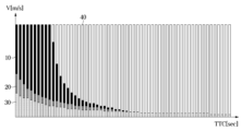
具体的に、図2は、本発明の一実施の形態に係る車両衝突試験方法における衝突余裕時間(TTC)要因および車両速度(V)要因を考慮したシナリオの危険度を示したグラフである。 Specifically, FIG. 2 is a graph showing the risk of scenarios taking into account time to collision (TTC) factors and vehicle speed (V) factors in a vehicle crash test method according to one embodiment of the present invention.
図2における、X軸は、衝突余裕時間[sec]を意味し、Y軸は、車両速度[m/s]を意味する。車両速度とは、車両衝突試験方法内で設定するようになるターゲット車両2の速度を意味する。車両衝突試験方法内で試験の対象になる対象車両1は、設定されたターゲット車両2の速度を追従するので、ターゲット車両2と対象車両1の速度は、車両速度(V)で同一であることと仮定する。
In FIG. 2, the X-axis represents the time to collision [sec], and the Y-axis represents the vehicle speed [m/s]. The vehicle speed means the speed of the
図2では、2つの要因だけを考慮したシナリオを表示したが、車両衝突試験方法において考慮される要因は、TTC及び車両速度以外に減加速度(m/s2)、道路傾斜(%)、対象車両1およびターゲット車両2の初期相対距離など、多様な要因が追加されることができる。
FIG. 2 shows a scenario that takes into account only two factors, but in addition to the TTC and vehicle speed, various other factors can be added to the factors considered in the vehicle crash test method, such as deceleration (m/ s2 ), road slope (%), and initial relative distance between the
図2を具体的に見ると、「回避できないシナリオ(Not avoidable scenarios)10」は、黒色領域で表示した。TTCが小さいほど、車両速度が大きいほど「回避できないシナリオ」にあたるようになる。「失敗シナリオ(Failure scenarios)20」は、「回避できないシナリオ」よりは安全であるが、安全であると認められないシナリオであり、これは灰色で表示した領域である。「クリティカルシナリオ(critical scenarios)30」は、比較的安全であると認められるシナリオであって、これは淡灰色で表示した。最後に、白色領域は「通常シナリオ(Nominal Scenarios)40」であって、衝突状況と認められない一般的な走行状況を表示した。
Looking specifically at Figure 2, "Not
これらのシナリオは、考慮すべき要因(factors)の種類と各要因別の当該区間の個数に応じて、その組み合わせが多様に生成されることができる。 These scenarios can be generated in a variety of combinations depending on the types of factors to be considered and the number of intervals for each factor.
一例として、車両速度(V)は、10km/hrから110km/hrの範囲で10km/hrごとに11個の区間で設定されることができる。他の一例として、ターゲット車両の減速度は、0m/s2から8.33m/s2の範囲で、1m/s2ごとに9個の区間で設定されることができる。したがって、車両速度とターゲット車両の減速度の要因を組み合わせたシナリオは、11*9、すなわち99個のシナリオが生成されることができる。 As an example, the vehicle speed (V) can be set in 11 intervals of 10 km/hr in the range of 10 km/hr to 110 km/hr. As another example, the deceleration of the target vehicle can be set in 9 intervals of 1 m/ s2 in the range of 0 m/ s2 to 8.33 m/ s2 . Therefore, the scenarios combining the factors of the vehicle speed and the deceleration of the target vehicle can be generated as 11*9, i.e., 99 scenarios.
たとえば、車両衝突試験方法では99個のシナリオに対するサンプリングを行うことができる。サンプリングは、臨界TTCを設定し、当該臨界TTC以下のシナリオに対して最終的に選択シナリオとして選定することが可能である。 For example, in a vehicle crash test method, sampling can be performed for 99 scenarios. Sampling can be performed by setting a critical TTC, and ultimately selecting scenarios below that critical TTC as the selected scenario.
たとえば、前述した99個のシナリオの中で、臨界TTCを1.5[sec]に選定した場合、最終サンプリングされた選択シナリオは22個に縮めることができる。臨界TTCを決定することは、図6~図8において後述する。 For example, if the critical TTC is selected to be 1.5 sec among the 99 scenarios mentioned above, the final sampled selected scenarios can be reduced to 22. Determining the critical TTC will be described later in Figures 6 to 8.
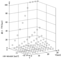
次に、図3は、本発明の一実施の形態に係る車両衝突試験方法によって生成された各シナリオ別車両速度(TSV及びVUT)、減加速度、及び最小TTCを示したグラフである。 Next, FIG. 3 is a graph showing vehicle speed (TSV and VUT), deceleration, and minimum TTC for each scenario generated by a vehicle crash test method according to one embodiment of the present invention.
図3における、X軸は、ターゲット車両2及び対象車両1の速度[m/s]を意味し、Y軸は、目標減加速度[m/s2]を意味し、Z軸は、最小TTCを意味する。図2と同様に、車両衝突試験方法内における試験の対象となる対象車両1は、設定されたターゲット車両2の速度を追従するので、ターゲット車両2と対象車両1の速度は、車両速度(V)で等しいことと仮定する。
3, the X-axis represents the speeds [m/s] of the
図3の各点は、前述したシナリオの組み合わせに対応するように表示した。すなわち、10km/hrから110km/hrの範囲で、10km/hrごとに生成された11個の区間別車両速度と、0m/s2から8.33m/s2の範囲で1m/s2ごとに生成された9個の区間別ターゲット車両の減速度の組み合わせに対する99個のシナリオ、および、各シナリオに対応する最小TTCを示した。 Each point in Fig. 3 corresponds to a combination of the above-mentioned scenarios, i.e., 99 scenarios for combinations of 11 section vehicle speeds generated every 10 km/hr in the range from 10 km/hr to 110 km/hr and 9 section target vehicle decelerations generated every 1 m/ s2 in the range from 0 m/ s2 to 8.33 m/ s2 , and the minimum TTC corresponding to each scenario are shown.
車両衝突試験方法では99個のシナリオに対するサンプリングを行うことができる。サンプリングは、臨界TTCを設定し、当該臨界TTC以下のシナリオの中で最終的に一部を選択シナリオとして選定することが可能である。 The vehicle crash test method allows sampling of 99 scenarios. Sampling involves setting a critical TTC, and ultimately selecting a portion of the scenarios below that critical TTC as selected scenarios.
図4は、本発明の一実施の形態に係る衝突試験方法における臨界TTC未満のシナリオ別危険度を示したグラフである。たとえば、図4は、臨界TTCを1.5に設定した場合に、臨界TTC未満の選択シナリオに対するグラフである。ここで、X軸は車両速度を意味し、Y軸は減加速度を意味する。 Figure 4 is a graph showing the risk of each scenario below the critical TTC in a crash test method according to one embodiment of the present invention. For example, Figure 4 is a graph for selected scenarios below the critical TTC when the critical TTC is set to 1.5. Here, the X-axis represents vehicle speed and the Y-axis represents deceleration.
すなわち、前述した99個のシナリオの中で、臨界TTCを1.5[sec]に選定した場合、最終サンプリングされた選択シナリオは22個となる。 In other words, if the critical TTC is selected to be 1.5 [sec] among the 99 scenarios mentioned above, the final sampled selected scenarios will be 22.
また、図4ではシナリオごとに危険度を異なるように表示した。
具体的に、22個のシナリオに対して、危険度が高いシナリオであるほど、濃く表示されたことを確認することができる。図4では、24個のポイント(pt)が表示されているが、この中2個のポイントは衝突を回避できないシナリオであるため、最終シナリオ数の計数には含まれない。
In addition, in FIG. 4, the degree of risk is displayed differently for each scenario.
Specifically, it can be seen that, for the 22 scenarios, the more dangerous the scenario, the darker the displayed color. In FIG. 4, 24 points (pt) are displayed, but two of these points are scenarios in which a collision cannot be avoided, and therefore are not included in the final scenario count.
すなわち、車両速度が早いほど、臨界TTC未満の衝突余裕時間を持つシナリオが少なく、相対的に危険度は低くなり、車両速度が遅いほど、臨界TTC未満の衝突余裕時間を持つシナリオが多く、相対的に危険度が大きくなることが分かる。 In other words, the faster the vehicle speed, the fewer the scenarios with a crash time below the critical TTC, and the lower the relative risk; the slower the vehicle speed, the more scenarios with a crash time below the critical TTC, and the higher the relative risk.
次に、図5は、本発明の一実施の形態に係る衝突試験方法によって生成された各シナリオ別に車両速度(TSV及びVUT)、減加速度、及び最小TTCを示したグラフであって、最大減速度にあたるシナリオを陰影表示したグラフである。 Next, FIG. 5 is a graph showing vehicle speed (TSV and VUT), deceleration, and minimum TTC for each scenario generated by a crash test method according to one embodiment of the present invention, in which the scenario corresponding to maximum deceleration is shaded.
すなわち、図4~図5から、車両衝突試験方法において、最大減速度を持つか、または車両速度が最低速度を持つようになる場合であれば、臨界TTCよりも小さい値で選択シナリオに選定される可能性が高くなることを確認することができる。 In other words, from Figures 4 and 5, it can be seen that in the vehicle crash test method, if the vehicle has a maximum deceleration or a minimum vehicle speed, the scenario is more likely to be selected at a value smaller than the critical TTC.
次いで、図6では運転者モデルについて説明する。運転者モデルの場合、図1に示された対象車両1がターゲット車両2を追従するように、高速道路内での走行を一例として挙げられる。運転者モデルは、対象車両1がターゲット車両2と一定した安全距離(safe distance)を置いて走行中であるとき、ターゲット車両2の突然な減速(sudden deceleration)に因る自動減速機能を観察するためのシナリオを選定するためである。
Next, the driver model will be described with reference to FIG. 6. In the case of the driver model, an example is driving on a highway, where the
図6に示されているように、実際に対象車両1を運転者が運転すると仮定する時、実際に運転者が危険認知時点p1にターゲット車両2の減速を初めて認知したとしても、危ないと決定を下す時点p3までは、続いてアクセルペダルを踏むようになる。
As shown in FIG. 6, assuming that a driver is actually driving the
したがって、危ないという決定を下す時点p3を経てアクセルペダルを解除する区間p3~p4と、アクセルペダルからブレーキペダルへの運転者の足移動区間p4~p5を経て、p5時点からブレーキペダルが結合し始める。 Therefore, after the point p3 where it is decided that it is dangerous, there is a section p3-p4 where the accelerator pedal is released, and then a section p4-p5 where the driver's foot moves from the accelerator pedal to the brake pedal, and from point p5 the brake pedal begins to engage.
また、運転者のブレーキペダルの加圧は、p5時点から行われるが、ブレーキ作動開始区間であるp5~p6を経て実際の減速はp6時点から対象車両1の減速が行われるようになる。
The driver begins to apply pressure to the brake pedal at p5, but the
したがって、危険認知区間は、実際にターゲット車両2が減速を開始してから始まるので、衝突余裕時間TTCは下記の式1で算出されることができる。
Therefore, since the hazard recognition section actually begins when the
(数1)
TTC=drel/vrel=drel/(Vvut-Vtsv)
(Equation 1)
TTC = d rel / v rel = d rel / (V vut - V tsv )
ここで、TTCとは、衝突余裕時間を意味し、drelは、ターゲット車両(tsv)2と対象車両(vut)1との間の距離を意味し、vrelは、ターゲット車両(tsv)2と対象車両(vut)1との間の相対速度を意味し、Vtsvは、ターゲット車両(tsv)2の速度、Vvutは、対象車両(vut)1の速度を意味する。 Here, TTC means time to collision, d rel means the distance between the target vehicle (tsv) 2 and the target vehicle (vut) 1, v rel means the relative speed between the target vehicle (tsv) 2 and the target vehicle (vut) 1, V tsv means the speed of the target vehicle (tsv) 2, and V vut means the speed of the target vehicle (vut) 1.
車両衝突試験方法において、TTCは、0.01[sec]時間間隔ごとに算出されることができる。この時、算出されたTTCが危険シナリオに属する場合、当該情報を保存することが可能である。 In the vehicle crash test method, the TTC can be calculated every 0.01 [sec] time interval. At this time, if the calculated TTC belongs to a dangerous scenario, the information can be stored.
車両衝突試験方法は、システム、またはコンピューターで読み取り可能な記録媒体に格納されたプログラム上で動作されることが可能である。たとえば、車両衝突試験方法が動作されるシステム内の制御部(図示せず)は、車両衝突試験方法を総括的に制御する。また、車両衝突試験方法が動作されるシステムは、ストレージ部(storage)を含むものであって、マトリックス形式でデータ値を保存する。 The vehicle crash test method can be operated on a system or a program stored on a computer-readable recording medium. For example, a control unit (not shown) in the system in which the vehicle crash test method is operated controls the vehicle crash test method as a whole. In addition, the system in which the vehicle crash test method is operated includes a storage unit, which stores data values in a matrix format.
すなわち、ストレージ部は、キャッシュ、ROM(Read Only Memory)、PROM(Programmable ROM)、EPROM(Erasable Programmable ROM)、EEPROM(Electrically Erasable Programmable ROM)、及びフラッシュメモリー(Flash memory)のような不揮発性メモリー素子またはRAM(Random Access Memory)のような揮発性メモリー素子またはハードディスクドライブ(HDD;Hard Disk Drive)、CD-ROMのような記憶媒体の中で少なくとも一つで具現されることができ、これらに限定されない。 That is, the storage unit can be embodied as at least one of a cache, a ROM (Read Only Memory), a PROM (Programmable ROM), an EPROM (Erasable Programmable ROM), an EEPROM (Electrically Erasable Programmable ROM), and a non-volatile memory element such as a flash memory, a volatile memory element such as a RAM (Random Access Memory), or a storage medium such as a hard disk drive (HDD) or a CD-ROM, but is not limited to these.
すなわち、ストレージ部は、前述した制御部と別個のチップで具現されたメモリーであってもよく、プロセッサと単一チップで具現されてもよい。 That is, the storage unit may be a memory implemented as a chip separate from the control unit, or may be implemented as a single chip with the processor.
以上では、車両衝突試験方法のシナリオについて説明した。以下では、図6で説明した運転者モデルで説明されたTTC、それぞれの危険認知、危険決定、危険対応区間と車速を考慮した変数選定を通じてシナリオ動作方法について説明する。 The above describes the scenario for the vehicle crash test method. Below, we will explain how the scenario operates through variable selection that takes into account the TTC explained in the driver model described in Figure 6, each hazard recognition, hazard decision, hazard response section, and vehicle speed.
図7は、本発明の一実施の形態に係る衝突試験方法のフローチャートである。 Figure 7 is a flowchart of a crash test method according to one embodiment of the present invention.
まず、図7に示されているように、シナリオを算出するために変数を設定する(ステップ700)。例えば、車両衝突試験方法で考慮される要因は、TTC及び車両速度以外に、減加速度[m/s2]、道路傾斜[%]、対象車両1およびターゲット車両2の初期相対距離など、多様な変数がこれにあたることができる。
First, as shown in Fig. 7, variables are set to calculate a scenario (step 700). For example, factors considered in the vehicle crash test method may include various variables such as deceleration [m/ s2 ], road slope [%], and initial relative distance between the
次に、変数の組み合わせを算出する(ステップ710)。例えば、11区間で車両速度(V)を区間設定し、目標減加速度は、9個で区間設定するようになると、車両速度と目標の減加速度とを組み合わせたシナリオは、すなわち、99個のシナリオが生成されることができる。 Next, the combination of variables is calculated (step 710). For example, if the vehicle speed (V) is set to 11 intervals and the target deceleration is set to 9 intervals, then 99 scenarios can be generated that combine the vehicle speed and the target deceleration.
最後に、算出されたシナリオを適用した結果値を保存する。一例として、前述の99個のシナリオに対しては、99個のシナリオに応じた結果値を保存する(ステップ720)。ここで、図7は、シナリオ導出について説明しているが、導出されたシナリオに基づく結果値を保存するステップ720は、後述する図8で詳細に説明する。 Finally, the result values obtained by applying the calculated scenarios are stored. As an example, for the 99 scenarios mentioned above, the result values corresponding to the 99 scenarios are stored (step 720). Here, FIG. 7 explains the scenario derivation, but step 720 of storing the result values based on the derived scenarios will be explained in detail in FIG. 8 described later.
次に、図8は、本発明の一実施の形態に係る衝突試験方法によるシナリオを説明するフローチャートである。 Next, FIG. 8 is a flowchart explaining a scenario according to a crash test method according to one embodiment of the present invention.
図8では、一実施の形態に係る衝突試験方法によって、減加速度及び車両速度を利用して生成された99個のシナリオの適用過程を説明する過程を示したフローチャートである。 Figure 8 is a flowchart illustrating the process of applying 99 scenarios generated using deceleration and vehicle speed according to a crash testing method according to one embodiment.
衝突試験方法では、対象車両1の動作を試験するためのものであって、ターゲット車両2を制御する。ターゲット車両が減速すると(ステップ810の「はい」)、ターゲット車両の減速開始時点から予め設定した第1の臨界時間th1を超えると、対象車両が減速し始める(ステップ830)。
The crash test method tests the operation of a
臨界時間th1は、図6の運転者モデルで説明したように、ターゲット車両2が減速し始めても、実際に運転者、あるいは、自律走行システムがターゲット車両2の減速を危険と認知する危険決定時間および危険対応時間が所要された以後、実際に減速が行われることを考慮した時間である。つまり、危険を認知して危険決定と判断する時間と、実際にブレーキペダルが踏まれるまでの機械的時間とを考慮して設定されることができる。
As explained in the driver model of FIG. 6, the critical time th1 is a time that takes into consideration that even if the
図8における臨界時間th1は、ターゲット車両2と対象車両1とが等しい速度で走行中であるとき、ターゲット車両2が減速し始めることを仮定して、危険決定判断時間と、ブレーキペダルが踏まれるまでの機械的時間を遂行する機械的時間とを考慮して決定するのが可能である。
The critical time th1 in FIG. 8 can be determined by assuming that the
ただし、臨界時間th1は、ターゲット車両2の同じ速度ではない場合には、臨界時間th1を補正して設定することも可能である。
However, if the
一例として、ターゲット車両2が加速走行中であり、対象車両1も加速走行中であるとき、ターゲット車両2が減速をする場合であれば、臨界時間th1に補正値を足して第1の臨界時間を設定してもよい。この時、補正値は、ターゲット車両2の加速程度と、対象車両1の加速走行の程度に応じて、細分化して設定されることが可能である。この時、ターゲット車両2と対象車両1の加速程度、すなわち加速度の大きさを比較して細分化してもよい。
As an example, when the
また、これと異なり、ターゲット車両2が加速走行であるが、対象車両1は減速をする場合であれば、臨界時間th1に負(-)の補正値を与えて、第1の臨界時間を設定することも可能である。
Alternatively, if the
次に、対象車両の減速が行われ始め(ステップ830)、TTCを算出する(ステップ840)。具体的に、一実施の形態に係る車両衝突試験方法によれば、TTCは0.01[sec]時間間隔ごとに算出されることができる。 Next, the target vehicle begins to decelerate (step 830), and the TTC is calculated (step 840). Specifically, according to one embodiment of the vehicle crash test method, the TTC can be calculated every 0.01 [sec] time interval.
したがって、毎時間(0.01sec間隔)ごとに算出されたTTCを、予め設定した第2の臨界時間th2と比較する(ステップ850)。具体的に、第2の臨界時間th2は、第1の臨界時間th1よりも長く設定されることができる。 Therefore, the TTC calculated every hour (at 0.01 sec intervals) is compared with a preset second critical time th2 (step 850). Specifically, the second critical time th2 can be set to be longer than the first critical time th1.
もし、算出されたTTCが第2の臨界時間未満であり(ステップ850の「はい」)、対象車両が止まった場合であれば(ステップ860の「はい」)、選択シナリオ(危険)であって、当該変数のパラメーターをマトリックス形式で保存する。 If the calculated TTC is less than the second critical time (step 850: YES) and the target vehicle has stopped (step 860: YES), the selected scenario is (Danger) and the parameters of the variable are saved in matrix format.
前記ステップ860では、対象車両が止まった場合(すなわち、対象車両速度が0である場合)に対する実施形態として説明したが、対象車両が止まった場合だけではなく、対象車両1の変位(location)とターゲット車両2の変位とが同じ場合も、選択シナリオとして選択され得る。
In
選択シナリオとして選択された場合は危険状況であって、保存されたマトリックス形式によって別途の出力値を生成するのが可能である。 When selected as a selection scenario, it is a dangerous situation, and a separate output value can be generated according to the saved matrix format.
例えば、対象車両1に車両衝突試験方法を導入して保存される選択シナリオ及び非選択シナリオを分析し、それぞれのシナリオに対する保存頻度を考慮したビッグデータとして対象車両1の運転習慣を分析し得る。
For example, a vehicle crash test method can be introduced to the
これと異なり、もし算出されたTTCが第2の臨界時間よりも長ければ(ステップ850の「いいえ」)、TTCが危なくないもので、当該シナリオは非選択シナリオとして当該変数のパラメーターをマトリックス形式で保存することも可能である。 In contrast, if the calculated TTC is longer than the second critical time ("No" in step 850), the TTC is not critical, and the scenario can be saved as a non-selected scenario with the parameters of the variables in matrix format.
また、選択シナリオまたは非選択シナリオとしてマトリックス形式で保存することによって、個別シナリオに対する変数をすべて保存することで、個別シナリオのそれぞれに対して最小TTC値と比較して、各シナリオ別の優先順位を導出することもできる。 Also, by saving all the variables for each individual scenario in a matrix format as selected or non-selected scenarios, it is possible to derive a priority for each scenario by comparing it with the minimum TTC value for each individual scenario.
以上の説明は、本発明の技術思想を例示的に説明したものに過ぎなく、本発明の属する技術分野における通常の知識を持つ者なら、本発明の本質的な特性から逸脱しない範囲内で多様な修正及び変形が可能である。したがって、本発明に開示された実施形態は、本発明の技術思想を限定するためではなく、説明するためのものであって、これらの実施形態によって本発明の技術思想の範囲が限定されるものではない。本発明の保護範囲は、下記請求範囲によって解釈されなければならなく、それと同等な範囲内に属するすべての技術思想は本発明の権利範囲に含まれるものと解釈されなければならない。 The above description is merely an illustrative example of the technical concept of the present invention, and various modifications and variations are possible within the scope of the essential characteristics of the present invention, for those with ordinary knowledge in the technical field to which the present invention pertains. Therefore, the embodiments disclosed in the present invention are intended to illustrate, not limit, the technical concept of the present invention, and the scope of the technical concept of the present invention is not limited by these embodiments. The scope of protection of the present invention should be interpreted according to the claims below, and all technical concepts within the scope equivalent thereto should be interpreted as being included in the scope of the present invention.
1 対象車両
2 ターゲット車両
10 回避できないシナリオ
20 失敗シナリオ
30 クリティカルシナリオ
40 通常シナリオ
1.
Claims (8)
ターゲット車両の速度及び目標加速度を設定する段階と、
前記ターゲット車両の設定された速度及び目標加速度に対応して対象車両の速度及び加速度を観測する段階と、
前記ターゲット車両の減速以後、第1の臨界時間超えの場合は、前記対象車両を減速させて、衝突余裕時間(TTC:Time to Collision)を算出する段階と、
前記算出された衝突余裕時間が、第1の臨界時間よりも長い、第2の臨界時間未満であれば、前記対象車両の情報を保存する段階と、
を含み、
前記算出された衝突余裕時間が、第1の臨界時間よりも長い、第2の臨界時間未満であれば、前記対象車両の情報を保存する段階は、
前記ターゲット車両の速度を区間間隔で分けて設定する段階と、
前記ターゲット車両の加速度を区間間隔で分けて設定する段階と、
設定された前記ターゲット車両の速度に対する区間間隔と設定されたターゲット車両の加速度に対する区間間隔との組み合わせにより複数のシナリオを選定する段階と、
複数のシナリオに対して算出された衝突余裕時間が第2の臨界時間未満の場合、選択シナリオとして選定する段階と、を含み、
前記第1の臨界時間は、前記ターゲット車両の減速に対応して対象車両が減速し始めるまでに要する時間であり、前記対象車両の危険決定判断時間及びペダル切り替え(transfer)の機械的時間を考慮して予め設定される時間であり、
前記衝突余裕時間は、下記の式:
(数1)
TTC=d rel /v rel =d rel /(V vut -V tsv )
(ただし、d rel は、ターゲット車両(tsv)と対象車両(vut)との間の距離であり、v rel は、ターゲット車両(tsv)と対象車両(vut)との間の相対速度であり、V tsv は、ターゲット車両(tsv)の速度、V vut は、対象車両(vut)の速度である)
で算出され、
前記対象車両の情報は、前記対象車両の速度、加速度、予め設定された時間間隔ごとに算出される衝突余裕時間を含む、車両衝突試験方法。 A vehicle crash test method for selecting a scenario suitable for a vehicle crash test, comprising:
setting a target vehicle speed and a target acceleration;
observing a speed and an acceleration of a target vehicle corresponding to a set speed and a target acceleration of the target vehicle;
If a first critical time has elapsed since the deceleration of the target vehicle, decelerating the target vehicle and calculating a time to collision (TTC);
storing information of the target vehicle if the calculated time to collision is longer than a first critical time and shorter than a second critical time;
Including,
If the calculated time to collision is longer than a first critical time and shorter than a second critical time, storing the information of the target vehicle includes:
setting a speed of the target vehicle at intervals;
setting the acceleration of the target vehicle at intervals;
selecting a plurality of scenarios according to a combination of a section interval for the set speed of the target vehicle and a section interval for the set acceleration of the target vehicle;
selecting a scenario as a selected scenario when the calculated collision time to collision for each of the plurality of scenarios is less than a second critical time ;
The first critical time is a time required for the target vehicle to start decelerating in response to the deceleration of the target vehicle, and is a time that is preset in consideration of a risk determination time of the target vehicle and a mechanical time of pedal transfer;
The collision margin time is calculated by the following formula:
(Equation 1)
TTC = d rel / v rel = d rel / (V vut - V tsv )
(where d rel is the distance between the target vehicle (tsv) and the target vehicle (vut), v rel is the relative speed between the target vehicle (tsv) and the target vehicle (vut), V tsv is the speed of the target vehicle (tsv), and V vut is the speed of the target vehicle (vut).
It is calculated as
A vehicle crash testing method , wherein the information on the target vehicle includes the speed and acceleration of the target vehicle, and a time to collision calculated at each preset time interval .
予め設定した時間間隔ごとに前記対象車両の衝突余裕時間を算出する段階と、
算出された衝突余裕時間の中で最小衝突余裕時間を選択シナリオとして選定する段階と、を含む、請求項1に記載の車両衝突試験方法。 When the collision time to collision calculated for the plurality of scenarios is less than the second critical time, the step of selecting the selected scenario includes:
calculating a time to collision of the target vehicle at each preset time interval;
The vehicle crash test method according to claim 1 , further comprising: a step of selecting a minimum crash time to collision as a selected scenario from among the calculated crash time to collisions.
前記最小衝突余裕時間が前記第2の臨界時間未満の場合、選択シナリオとして保存する段階と、
前記最小衝突余裕時間が前記第2の臨界時間超過の場合、非選択シナリオとして保存する段階と、を含む、請求項2に記載の車両衝突試験方法。 The step of selecting a minimum collision margin time from the calculated collision margin times as a selection scenario includes:
If the minimum collision time is less than the second critical time, storing the selected scenario;
3. The vehicle crash test method according to claim 2, further comprising the step of: storing the scenario as a non-selected scenario if the minimum crash time exceeds the second critical time.
前記選択シナリオまたは前記非選択シナリオとして保存された対象車両の走行情報をマトリックス形態で保存する段階と、
前記保存された対象車両の走行情報に基づいて前記対象車両の運転習慣を分析する段階と、をさらに含む請求項3に記載の車両衝突試験方法。 The step of selecting a minimum collision margin time from the calculated collision margin times as a selection scenario includes:
storing driving information of the target vehicle stored as the selected scenario or the non-selected scenario in a matrix form;
The method of claim 3 , further comprising: analyzing a driving habit of the target vehicle based on the stored driving information of the target vehicle.
Applications Claiming Priority (2)
| Application Number | Priority Date | Filing Date | Title |
|---|---|---|---|
| KR1020220102537A KR102562790B1 (en) | 2022-08-17 | 2022-08-17 | Vehicle collision test method |
| KR10-2022-0102537 | 2022-08-17 |
Publications (2)
| Publication Number | Publication Date |
|---|---|
| JP2024028208A JP2024028208A (en) | 2024-03-01 |
| JP7476412B2 true JP7476412B2 (en) | 2024-04-30 |
Family
ID=87561171
Family Applications (1)
| Application Number | Title | Priority Date | Filing Date |
|---|---|---|---|
| JP2023132755A Active JP7476412B2 (en) | 2022-08-17 | 2023-08-17 | Vehicle crash test method |
Country Status (4)
| Country | Link |
|---|---|
| US (1) | US20240062591A1 (en) |
| EP (1) | EP4350320A1 (en) |
| JP (1) | JP7476412B2 (en) |
| KR (1) | KR102562790B1 (en) |
Citations (3)
| Publication number | Priority date | Publication date | Assignee | Title |
|---|---|---|---|---|
| JP2011121491A (en) | 2009-12-11 | 2011-06-23 | Toyota Motor Corp | Driving support device |
| JP2020142557A (en) | 2019-03-04 | 2020-09-10 | 独立行政法人自動車技術総合機構 | Brake evaluation device, brake evaluation method, evaluation threshold generation method for automatic brake pattern, and basic data collection method for automatic brake pattern |
| WO2022130718A1 (en) | 2020-12-18 | 2022-06-23 | 日立Astemo株式会社 | Information generation device |
Family Cites Families (2)
| Publication number | Priority date | Publication date | Assignee | Title |
|---|---|---|---|---|
| JP3758970B2 (en) * | 2000-11-24 | 2006-03-22 | アイシン精機株式会社 | Vehicle collision prevention device |
| DE102010051203B4 (en) * | 2010-11-12 | 2022-07-28 | Zf Active Safety Gmbh | Method for detecting critical driving situations in trucks or passenger vehicles, in particular for avoiding collisions |
-
2022
- 2022-08-17 KR KR1020220102537A patent/KR102562790B1/en active IP Right Grant
-
2023
- 2023-08-17 EP EP23191941.6A patent/EP4350320A1/en active Pending
- 2023-08-17 JP JP2023132755A patent/JP7476412B2/en active Active
- 2023-08-17 US US18/451,603 patent/US20240062591A1/en active Pending
Patent Citations (3)
| Publication number | Priority date | Publication date | Assignee | Title |
|---|---|---|---|---|
| JP2011121491A (en) | 2009-12-11 | 2011-06-23 | Toyota Motor Corp | Driving support device |
| JP2020142557A (en) | 2019-03-04 | 2020-09-10 | 独立行政法人自動車技術総合機構 | Brake evaluation device, brake evaluation method, evaluation threshold generation method for automatic brake pattern, and basic data collection method for automatic brake pattern |
| WO2022130718A1 (en) | 2020-12-18 | 2022-06-23 | 日立Astemo株式会社 | Information generation device |
Also Published As
| Publication number | Publication date |
|---|---|
| US20240062591A1 (en) | 2024-02-22 |
| KR102562790B1 (en) | 2023-08-07 |
| EP4350320A1 (en) | 2024-04-10 |
| JP2024028208A (en) | 2024-03-01 |
Similar Documents
| Publication | Publication Date | Title |
|---|---|---|
| US8396642B2 (en) | Adaptive cruise control system | |
| US8195373B2 (en) | Vehicle driver assistance system and method | |
| US7840354B2 (en) | Method and device for automatically triggering a vehicle deceleration | |
| US6084508A (en) | Automatic emergency braking method and arrangement | |
| US8386124B2 (en) | Method and device for stabilizing a vehicle after a collision | |
| US7138909B2 (en) | Device for providing signals in a motor vehicle | |
| US8396655B2 (en) | Motor vehicle control system | |
| US9956959B2 (en) | Method for controlling a delay device of a vehicle | |
| US7103464B2 (en) | Automatic distance control method and system for motor vehicles | |
| US7715275B2 (en) | Start assist system for motor vehicles | |
| US11713041B2 (en) | Control system and control method for driving a motor vehicle | |
| CN106564502B (en) | method and device for determining the adaptive response time of a driver of a motor vehicle | |
| US11292463B2 (en) | Determination of a control signal for an in-part-autonomous vehicle | |
| US20140025270A1 (en) | Radar initiated foundation braking only for autonomous emergency braking situations | |
| KR102002421B1 (en) | Adaptive cruise control apparatus and method of operating adaptive cruise control in consideration of traffic condition | |
| US20170158205A1 (en) | Method, computer program, storage medium and electronic control unit for operating a vehicle | |
| US11273823B2 (en) | Method for determining a maximum speed of a vehicle during a parking maneuver | |
| US10399568B2 (en) | Method and device for automatic longitudinal dynamics control of a motor vehicle | |
| JP7476412B2 (en) | Vehicle crash test method | |
| KR20190067098A (en) | Method and control device for operating an electric vehicle or a hybrid vehicle | |
| KR20220026005A (en) | System for collision risk prediction of lane change based on radar sensors and method thereof | |
| CN109421687A (en) | Braking system delay self-learning method and computer readable storage medium | |
| US11919389B2 (en) | Vehicle and method of controlling vehicle speed at a road branching point | |
| KR102274802B1 (en) | Method for controling vehicle in abnornal situation of acc | |
| CN111204319A (en) | Method and device for determining target deceleration for own vehicle |
Legal Events
| Date | Code | Title | Description |
|---|---|---|---|
| A621 | Written request for application examination |
Free format text: JAPANESE INTERMEDIATE CODE: A621 Effective date: 20230818 |
|
| A871 | Explanation of circumstances concerning accelerated examination |
Free format text: JAPANESE INTERMEDIATE CODE: A871 Effective date: 20230818 |
|
| A131 | Notification of reasons for refusal |
Free format text: JAPANESE INTERMEDIATE CODE: A131 Effective date: 20231128 |
|
| A521 | Request for written amendment filed |
Free format text: JAPANESE INTERMEDIATE CODE: A523 Effective date: 20240221 |
|
| TRDD | Decision of grant or rejection written | ||
| A01 | Written decision to grant a patent or to grant a registration (utility model) |
Free format text: JAPANESE INTERMEDIATE CODE: A01 Effective date: 20240416 |
|
| A61 | First payment of annual fees (during grant procedure) |
Free format text: JAPANESE INTERMEDIATE CODE: A61 Effective date: 20240417 |
|
| R150 | Certificate of patent or registration of utility model |
Ref document number: 7476412 Country of ref document: JP Free format text: JAPANESE INTERMEDIATE CODE: R150 |