JP7465650B2 - Steam generators and waste heat recovery plants - Google Patents
Steam generators and waste heat recovery plants Download PDFInfo
- Publication number
- JP7465650B2 JP7465650B2 JP2019214824A JP2019214824A JP7465650B2 JP 7465650 B2 JP7465650 B2 JP 7465650B2 JP 2019214824 A JP2019214824 A JP 2019214824A JP 2019214824 A JP2019214824 A JP 2019214824A JP 7465650 B2 JP7465650 B2 JP 7465650B2
- Authority
- JP
- Japan
- Prior art keywords
- economizer
- water
- steam
- heat
- pressure
- Prior art date
- Legal status (The legal status is an assumption and is not a legal conclusion. Google has not performed a legal analysis and makes no representation as to the accuracy of the status listed.)
- Active
Links
- 238000011084 recovery Methods 0.000 title claims description 35
- 239000002918 waste heat Substances 0.000 title claims description 14
- XLYOFNOQVPJJNP-UHFFFAOYSA-N water Substances O XLYOFNOQVPJJNP-UHFFFAOYSA-N 0.000 claims description 594
- 239000007789 gas Substances 0.000 claims description 116
- 238000001816 cooling Methods 0.000 claims description 42
- 238000011144 upstream manufacturing Methods 0.000 claims description 29
- 239000002826 coolant Substances 0.000 claims description 20
- 239000000446 fuel Substances 0.000 claims description 17
- 239000008400 supply water Substances 0.000 claims description 17
- 239000007788 liquid Substances 0.000 claims description 14
- 238000012546 transfer Methods 0.000 claims description 10
- 238000010438 heat treatment Methods 0.000 claims description 9
- 238000002156 mixing Methods 0.000 claims description 6
- 238000010586 diagram Methods 0.000 description 49
- 229920006395 saturated elastomer Polymers 0.000 description 15
- 238000013459 approach Methods 0.000 description 10
- 238000009835 boiling Methods 0.000 description 9
- 230000000052 comparative effect Effects 0.000 description 9
- 230000007423 decrease Effects 0.000 description 7
- 230000000694 effects Effects 0.000 description 7
- 238000001704 evaporation Methods 0.000 description 7
- 238000010248 power generation Methods 0.000 description 7
- 238000009833 condensation Methods 0.000 description 5
- 230000005494 condensation Effects 0.000 description 5
- 230000008020 evaporation Effects 0.000 description 5
- 230000014509 gene expression Effects 0.000 description 5
- 238000000034 method Methods 0.000 description 5
- 238000000605 extraction Methods 0.000 description 4
- 239000008236 heating water Substances 0.000 description 4
- 239000003245 coal Substances 0.000 description 3
- 238000005260 corrosion Methods 0.000 description 3
- 230000007797 corrosion Effects 0.000 description 3
- 230000003628 erosive effect Effects 0.000 description 3
- 230000002349 favourable effect Effects 0.000 description 3
- 239000000314 lubricant Substances 0.000 description 3
- 239000000463 material Substances 0.000 description 3
- 239000003921 oil Substances 0.000 description 3
- OFBQJSOFQDEBGM-UHFFFAOYSA-N Pentane Chemical compound CCCCC OFBQJSOFQDEBGM-UHFFFAOYSA-N 0.000 description 2
- 230000003247 decreasing effect Effects 0.000 description 2
- 238000012986 modification Methods 0.000 description 2
- 230000004048 modification Effects 0.000 description 2
- XDTMQSROBMDMFD-UHFFFAOYSA-N Cyclohexane Chemical compound C1CCCCC1 XDTMQSROBMDMFD-UHFFFAOYSA-N 0.000 description 1
- 238000010521 absorption reaction Methods 0.000 description 1
- 238000004378 air conditioning Methods 0.000 description 1
- 238000006243 chemical reaction Methods 0.000 description 1
- 238000002485 combustion reaction Methods 0.000 description 1
- 238000007599 discharging Methods 0.000 description 1
- 238000006073 displacement reaction Methods 0.000 description 1
- 238000007710 freezing Methods 0.000 description 1
- 230000008014 freezing Effects 0.000 description 1
- 239000007791 liquid phase Substances 0.000 description 1
- 239000010687 lubricating oil Substances 0.000 description 1
- 238000004519 manufacturing process Methods 0.000 description 1
- MSSNHSVIGIHOJA-UHFFFAOYSA-N pentafluoropropane Chemical compound FC(F)CC(F)(F)F MSSNHSVIGIHOJA-UHFFFAOYSA-N 0.000 description 1
- 238000012545 processing Methods 0.000 description 1
- 229910001220 stainless steel Inorganic materials 0.000 description 1
- 239000010935 stainless steel Substances 0.000 description 1
- 239000003643 water by type Substances 0.000 description 1
Images


Classifications
-
- F—MECHANICAL ENGINEERING; LIGHTING; HEATING; WEAPONS; BLASTING
- F01—MACHINES OR ENGINES IN GENERAL; ENGINE PLANTS IN GENERAL; STEAM ENGINES
- F01K—STEAM ENGINE PLANTS; STEAM ACCUMULATORS; ENGINE PLANTS NOT OTHERWISE PROVIDED FOR; ENGINES USING SPECIAL WORKING FLUIDS OR CYCLES
- F01K7/00—Steam engine plants characterised by the use of specific types of engine; Plants or engines characterised by their use of special steam systems, cycles or processes; Control means specially adapted for such systems, cycles or processes; Use of withdrawn or exhaust steam for feed-water heating
- F01K7/16—Steam engine plants characterised by the use of specific types of engine; Plants or engines characterised by their use of special steam systems, cycles or processes; Control means specially adapted for such systems, cycles or processes; Use of withdrawn or exhaust steam for feed-water heating the engines being only of turbine type
-
- F—MECHANICAL ENGINEERING; LIGHTING; HEATING; WEAPONS; BLASTING
- F02—COMBUSTION ENGINES; HOT-GAS OR COMBUSTION-PRODUCT ENGINE PLANTS
- F02C—GAS-TURBINE PLANTS; AIR INTAKES FOR JET-PROPULSION PLANTS; CONTROLLING FUEL SUPPLY IN AIR-BREATHING JET-PROPULSION PLANTS
- F02C6/00—Plural gas-turbine plants; Combinations of gas-turbine plants with other apparatus; Adaptations of gas- turbine plants for special use
- F02C6/18—Plural gas-turbine plants; Combinations of gas-turbine plants with other apparatus; Adaptations of gas- turbine plants for special use using the waste heat of gas-turbine plants outside the plants themselves, e.g. gas-turbine power heat plants
-
- F—MECHANICAL ENGINEERING; LIGHTING; HEATING; WEAPONS; BLASTING
- F01—MACHINES OR ENGINES IN GENERAL; ENGINE PLANTS IN GENERAL; STEAM ENGINES
- F01K—STEAM ENGINE PLANTS; STEAM ACCUMULATORS; ENGINE PLANTS NOT OTHERWISE PROVIDED FOR; ENGINES USING SPECIAL WORKING FLUIDS OR CYCLES
- F01K23/00—Plants characterised by more than one engine delivering power external to the plant, the engines being driven by different fluids
- F01K23/02—Plants characterised by more than one engine delivering power external to the plant, the engines being driven by different fluids the engine cycles being thermally coupled
- F01K23/06—Plants characterised by more than one engine delivering power external to the plant, the engines being driven by different fluids the engine cycles being thermally coupled combustion heat from one cycle heating the fluid in another cycle
- F01K23/10—Plants characterised by more than one engine delivering power external to the plant, the engines being driven by different fluids the engine cycles being thermally coupled combustion heat from one cycle heating the fluid in another cycle with exhaust fluid of one cycle heating the fluid in another cycle
-
- F—MECHANICAL ENGINEERING; LIGHTING; HEATING; WEAPONS; BLASTING
- F22—STEAM GENERATION
- F22B—METHODS OF STEAM GENERATION; STEAM BOILERS
- F22B1/00—Methods of steam generation characterised by form of heating method
- F22B1/02—Methods of steam generation characterised by form of heating method by exploitation of the heat content of hot heat carriers
- F22B1/18—Methods of steam generation characterised by form of heating method by exploitation of the heat content of hot heat carriers the heat carrier being a hot gas, e.g. waste gas such as exhaust gas of internal-combustion engines
-
- F—MECHANICAL ENGINEERING; LIGHTING; HEATING; WEAPONS; BLASTING
- F22—STEAM GENERATION
- F22B—METHODS OF STEAM GENERATION; STEAM BOILERS
- F22B3/00—Other methods of steam generation; Steam boilers not provided for in other groups of this subclass
- F22B3/04—Other methods of steam generation; Steam boilers not provided for in other groups of this subclass by drop in pressure of high-pressure hot water within pressure- reducing chambers, e.g. in accumulators
-
- F—MECHANICAL ENGINEERING; LIGHTING; HEATING; WEAPONS; BLASTING
- F22—STEAM GENERATION
- F22D—PREHEATING, OR ACCUMULATING PREHEATED, FEED-WATER FOR STEAM GENERATION; FEED-WATER SUPPLY FOR STEAM GENERATION; CONTROLLING WATER LEVEL FOR STEAM GENERATION; AUXILIARY DEVICES FOR PROMOTING WATER CIRCULATION WITHIN STEAM BOILERS
- F22D1/00—Feed-water heaters, i.e. economisers or like preheaters
- F22D1/02—Feed-water heaters, i.e. economisers or like preheaters with water tubes arranged in the boiler furnace, fire tubes, or flue ways
-
- F—MECHANICAL ENGINEERING; LIGHTING; HEATING; WEAPONS; BLASTING
- F22—STEAM GENERATION
- F22D—PREHEATING, OR ACCUMULATING PREHEATED, FEED-WATER FOR STEAM GENERATION; FEED-WATER SUPPLY FOR STEAM GENERATION; CONTROLLING WATER LEVEL FOR STEAM GENERATION; AUXILIARY DEVICES FOR PROMOTING WATER CIRCULATION WITHIN STEAM BOILERS
- F22D5/00—Controlling water feed or water level; Automatic water feeding or water-level regulators
- F22D5/26—Automatic feed-control systems
- F22D5/36—Automatic feed-control systems for feeding a number of steam boilers designed for different ranges of temperature and pressure
-
- F—MECHANICAL ENGINEERING; LIGHTING; HEATING; WEAPONS; BLASTING
- F22—STEAM GENERATION
- F22G—SUPERHEATING OF STEAM
- F22G1/00—Steam superheating characterised by heating method
-
- Y—GENERAL TAGGING OF NEW TECHNOLOGICAL DEVELOPMENTS; GENERAL TAGGING OF CROSS-SECTIONAL TECHNOLOGIES SPANNING OVER SEVERAL SECTIONS OF THE IPC; TECHNICAL SUBJECTS COVERED BY FORMER USPC CROSS-REFERENCE ART COLLECTIONS [XRACs] AND DIGESTS
- Y02—TECHNOLOGIES OR APPLICATIONS FOR MITIGATION OR ADAPTATION AGAINST CLIMATE CHANGE
- Y02E—REDUCTION OF GREENHOUSE GAS [GHG] EMISSIONS, RELATED TO ENERGY GENERATION, TRANSMISSION OR DISTRIBUTION
- Y02E20/00—Combustion technologies with mitigation potential
- Y02E20/16—Combined cycle power plant [CCPP], or combined cycle gas turbine [CCGT]
Description
本開示は、蒸気発生装置及び排熱回収プラントに関する。 This disclosure relates to a steam generating apparatus and a waste heat recovery plant.
特許文献1には、ガスタービンの排気ガス(熱媒体)の熱を利用して節炭器に供給された給水を加熱し、節炭器から蒸発器に向かう給水の一部をフラッシュタンク(フラッシャー)に供給して、フラッシュタンクでフラッシュ蒸気を発生させる構成が開示されている。かかる構成によれば、節炭器を通過する比較的低温の排気ガスの熱を利用して蒸気を発生させることができ、排気ガスの熱利用の効率を高めることができる。 Patent Document 1 discloses a configuration in which the heat of the exhaust gas (heat medium) of a gas turbine is used to heat the feed water supplied to a coal economizer, and part of the feed water flowing from the coal economizer to the evaporator is supplied to a flash tank (flasher), generating flash steam in the flash tank. With this configuration, steam can be generated using the heat of the relatively low-temperature exhaust gas passing through the coal economizer, and the efficiency of exhaust gas heat utilization can be improved.
特許文献1に記載の構成では、フラッシュタンクを設けない場合と比較して、フラッシュタンクに供給する給水の流量に応じて節炭器に供給する給水の流量が多くなるため、節炭器に供給された給水の温度を飽和蒸気温度に近づけるために必要な節炭器のサイズが大きくなってしまう。また、フラッシュタンクを設けないシステムでも、節炭器から蒸発器に向かう給水の一部を熱利用設備に供給して熱源として利用するシステムでは同様に、節炭器に供給された給水の温度を飽和蒸気温度に近づけるために必要な節炭器のサイズが大きくなってしまう。 In the configuration described in Patent Document 1, the flow rate of the feedwater supplied to the economizer increases according to the flow rate of the feedwater supplied to the flash tank, compared to when a flash tank is not provided, and this results in a larger size of the economizer required to bring the temperature of the feedwater supplied to the economizer closer to the saturated steam temperature. Also, even in a system that does not have a flash tank, in a system in which a portion of the feedwater flowing from the economizer to the evaporator is supplied to a heat utilization facility and used as a heat source, the size of the economizer required to bring the temperature of the feedwater supplied to the economizer closer to the saturated steam temperature similarly becomes larger.
上述の事情に鑑みて、本開示は、節炭器のサイズの大型化を抑制しつつ、熱媒体の熱利用の効率を高めることができる蒸気発生装置及びこれを備える排熱回収プラントを提供することを目的とする。 In view of the above circumstances, the present disclosure aims to provide a steam generator that can increase the efficiency of heat utilization of the heat medium while suppressing an increase in the size of the economizer, and a waste heat recovery plant equipped with the same.
本開示の蒸気発生装置は、
熱媒体が流れる熱媒体流路と、
前記熱媒体流路に設けられた第1節炭器と、
前記熱媒体流路において前記熱媒体の流れ方向で前記第1節炭器の上流側に設けられた第2節炭器と、
前記熱媒体流路において前記熱媒体の流れ方向で前記第2節炭器の上流側に設けられた第1蒸発器と、
前記第1節炭器で加熱された水を前記第2節炭器に供給するように構成された第1給水ラインと、
前記第1給水ラインから分岐して設けられ、前記第1節炭器で加熱された水を熱利用設備に供給するように構成された第2給水ラインと、
を備える。
The steam generating device of the present disclosure comprises:
a heat medium flow path through which the heat medium flows;
A first economizer provided in the heat medium flow path;
a second economizer provided in the heat medium flow path on an upstream side of the first economizer in a flow direction of the heat medium;
a first evaporator provided in the heat medium flow path on an upstream side of the second economizer in a flow direction of the heat medium;
a first water supply line configured to supply water heated by the first economizer to the second economizer;
A second water supply line that is branched off from the first water supply line and is configured to supply the water heated by the first economizer to a heat utilization facility;
Equipped with.
本開示によれば、節炭器のサイズの大型化を抑制しつつ、熱媒体の熱利用の効率を高めることができる蒸気発生装置及びこれを備える排熱回収プラントが提供される。 The present disclosure provides a steam generator that can increase the efficiency of heat utilization of the heat medium while suppressing the increase in the size of the economizer, and a waste heat recovery plant equipped with the same.
以下、添付図面を参照して幾つかの実施形態について説明する。ただし、実施形態として記載されている又は図面に示されている構成部品の寸法、材質、形状、その相対的配置等は、発明の範囲をこれに限定する趣旨ではなく、単なる説明例にすぎない。
例えば、「ある方向に」、「ある方向に沿って」、「平行」、「直交」、「中心」、「同心」或いは「同軸」等の相対的或いは絶対的な配置を表す表現は、厳密にそのような配置を表すのみならず、公差、若しくは、同じ機能が得られる程度の角度や距離をもって相対的に変位している状態も表すものとする。
例えば、「同一」、「等しい」及び「均質」等の物事が等しい状態であることを表す表現は、厳密に等しい状態を表すのみならず、公差、若しくは、同じ機能が得られる程度の差が存在している状態も表すものとする。
例えば、四角形状や円筒形状等の形状を表す表現は、幾何学的に厳密な意味での四角形状や円筒形状等の形状を表すのみならず、同じ効果が得られる範囲で、凹凸部や面取り部等を含む形状も表すものとする。
一方、一の構成要素を「備える」、「具える」、「具備する」、「含む」、又は、「有する」という表現は、他の構成要素の存在を除外する排他的な表現ではない。
Hereinafter, some embodiments will be described with reference to the accompanying drawings. However, the dimensions, materials, shapes, relative arrangements, etc. of components described as the embodiments or shown in the drawings are merely illustrative examples and are not intended to limit the scope of the invention.
For example, expressions expressing relative or absolute configuration, such as "in a certain direction,""along a certain direction,""parallel,""orthogonal,""center,""concentric," or "coaxial," not only express such a configuration strictly, but also express a state in which there is a relative displacement with a tolerance or an angle or distance to the extent that the same function is obtained.
For example, expressions indicating that things are in an equal state, such as "identical,""equal," and "homogeneous," not only indicate a state of strict equality, but also indicate a state in which there is a tolerance or a difference to the extent that the same function is obtained.
For example, expressions describing shapes such as a rectangular shape or a cylindrical shape do not only refer to rectangular shapes, cylindrical shapes, etc. in the strict geometric sense, but also refer to shapes that include uneven portions, chamfered portions, etc., to the extent that the same effect is obtained.
On the other hand, the expressions "comprise,""include,""have,""includes," or "have" of one element are not exclusive expressions excluding the presence of other elements.
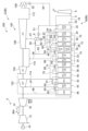
<コンバインドプラントの構成>
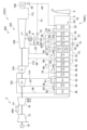
図1は、一実施形態に係るコンバインドプラント2(2A)の概略的な全体構成を示す図である。
コンバインドプラント2は、原動機としてのガスタービン4と、蒸気タービンシステム100と、排熱回収ボイラー5を含み蒸気を生成する蒸気発生装置6(6A)と、排熱回収ボイラー5から排出された排気ガスを大気に放出する煙突9と、を備える。蒸気タービンシステム100は、蒸気発生装置6で発生した蒸気を利用する蒸気利用設備として機能する。また、蒸気発生装置6及び蒸気タービンシステム100は、ガスタービン4の排熱を回収するための排熱回収プラント200を構成する。
<Combined plant configuration>
FIG. 1 is a diagram showing a schematic overall configuration of a combined plant 2 (2A) according to one embodiment.
The combined
<ガスタービンの構成>
ガスタービン4は、空気を圧縮する圧縮機12と、圧縮機12で生成された圧縮空気を用いて燃料を燃焼させる燃焼器14と、燃焼器14で生成された燃焼空気によって駆動されるタービン16とを含む。図示する形態では、圧縮機12及びタービン16と同一の軸線上に発電機19が配置されており、圧縮機12、タービン16及び発電機19の各々のロータが一体的に回転するように構成されている。
<Gas turbine configuration>
The
<蒸気タービンシステムの構成>
蒸気タービンシステム100は、複数の蒸気タービン102,104,106と、蒸気タービン106から排出された蒸気を冷却し、水に戻す復水器108とを備える。蒸気タービンシステム100は、複数の蒸気タービンとして、高圧蒸気タービン102と、中圧蒸気タービン104と、低圧蒸気タービン106とを含む。中圧蒸気タービン104の蒸気出口と低圧蒸気タービン106の蒸気入口とは中圧排気ライン110を介して接続されており、低圧蒸気タービン106の蒸気出口と復水器108とは低圧排気ライン112を介して接続されている。図示する形態では、圧縮機12、タービン16、発電機19、高圧蒸気タービン102、中圧蒸気タービン104及び低圧蒸気タービン106は、同一の軸線上に配置されており、各々のロータが一体的に回転するように構成されている。
<Configuration of Steam Turbine System>
The
<蒸気発生装置の構成>
蒸気発生装置6(6A)は、ガスタービン4の排気ガス(熱媒体)が供給される排熱回収ボイラー5と、第1フラッシュタンクとしてのフラッシュタンク8とを含む。また、フラッシュタンク8は加熱された水の供給を受けて、前記水の熱を用いて蒸気を発生させる熱利用設備でもある。
<Configuration of steam generating device>
The steam generating device 6 (6A) includes a
排熱回収ボイラー5は、ガスタービン4の排気ガスが流れる排気ガス流路18(熱媒体流路)と、排気ガス流路18に設けられた複数の熱交換器20とを含む。複数の熱交換器20は、排気ガス流路18の排気ガスの流れ方向において下流側から順に、第1低圧節炭器22(第1節炭器)、第2低圧節炭器24(第2節炭器)、低圧蒸発器26(第1蒸発器)、低圧過熱器28、第1高圧節炭器30、中圧蒸発器32、中圧過熱器34、第2高圧節炭器36、高圧蒸発器38、第1高圧過熱器40、第1再熱器42、第2高圧過熱器44及び第2再熱器46を含む。排気ガス流路18における排気ガスの流れ方向において、第2低圧節炭器24は第1低圧節炭器よりも上流側に位置し、低圧蒸発器26は第2低圧節炭器24よりも上流側に設けられている。排気ガス流路18における低圧過熱器28と中圧蒸発器32との間には、中圧節炭器31が第1高圧節炭器30と並設されている。
The
復水器108と第1低圧節炭器22とは、給水ライン48によって接続されており、給水ライン48には復水器108から出た復水を第1低圧節炭器22に供給するための復水ポンプ50が設けられている。
The
第1低圧節炭器22は、給水ライン48から供給された水を排気ガスとの熱交換により加熱する。第1低圧節炭器22で加熱された水の一部は、第1低圧節炭器22と第2低圧節炭器24とを接続する給水ライン52を介して第2低圧節炭器24へ供給される。
The first low-
フラッシュタンク8には、給水ライン52から分岐して設けられた給水ライン53が接続しており、第1低圧節炭器22で加熱された水の一部は、給水ライン53を介してフラッシュタンク8に供給される。給水ライン53には、第1低圧節炭器22から供給された加熱水を減圧するための減圧弁59が設けられている。給水ライン53を介してフラッシュタンク8に供給された加熱水は、フラッシュタンク8で減圧されて蒸発し(フラッシュし)、フラッシュ蒸気となる。フラッシュタンク8で生成されたフラッシュ蒸気は、フラッシュタンク8と低圧蒸気タービン106の中間段落とを接続する蒸気ライン57を介して低圧蒸気タービン106の中間段落に供給される。
A
フラッシュタンク8の底部に溜まった凝縮水は、フラッシュタンク8と給水ライン48とを接続する凝縮水ライン51を介して給水ライン48へ流入し、給水ライン48を介して第1低圧節炭器22に供給される。凝縮水ライン51には給水ポンプ61が設けられており、フラッシュタンク8から排出された凝縮水は給水ポンプ61により第1低圧節炭器22に圧送される。フラッシュタンク8から排出された凝縮水(例えば90℃)は、給水ライン48を流れる水(例えば35℃)よりも温度が高く、給水ライン48を流れる水は、フラッシュタンク8から排出された凝縮水と混合することにより、第1低圧節炭器22入口における給水温度(例えば60℃)まで温度が上昇する。こうすることにより、第1低圧節炭器22入口における給水の温度は、排気ガスの露点温度よりも高く保たれ、第1低圧節炭器22における排気ガス中の水分の凝縮を防止することができ、第1低圧節炭器22が比較的安価な材料で製作されている場合でも、腐食を防止することができる。
The condensed water accumulated at the bottom of the
本例においては、第1低圧節炭器22で加熱された水の一部は、給水ライン53を介してフラッシュタンク8に供給される。給水ライン53で供給された水の一部は、フラッシュタンク8で蒸発して低圧蒸気タービン106の駆動に用いられ、他の部分は、凝縮水として、給水ライン48を流れる水に混合し、給水ライン48を流れる水の加熱に用いられている。即ち、凝縮水ライン51と給水ポンプ61は、給水ライン48を流れる水に、給水ライン53で供給された水に由来する温度が高い凝縮水を混合することにより、給水ライン48を流れる水を加熱する熱利用設備を構成し、フラッシュタンク8と低圧蒸気タービン106は、給水ライン53で供給された水を熱源として動力を発生する動力発生装置を構成している。
In this example, a portion of the water heated by the first low-
一般に140℃~180℃となる低圧蒸発器26(第1蒸発器)入口給水を給水ライン48を流れる水に混合し、昇温に用いると必要以上に高温の熱を使ってしまうこととなり、熱利用効率が低い。給水ライン48を流れる水の昇温に、低圧蒸発器26(第1蒸発器)入口給水よりも低温の第1低圧節炭器22の出口から出た加熱水を用いることにより、低温の熱を有効に活用して吸気を加熱することができ、熱利用効率を高めることができる。100℃を超える温度の熱は常圧の水蒸気を発生させることができるのであり、100℃を超える温度の熱と100℃以下の熱では大きく利用価値が異なる。
If the inlet water supply to the low-pressure evaporator 26 (first evaporator), which is generally 140°C to 180°C, is mixed with the water flowing through the
従って、140℃~180℃の低圧蒸発器26(第1蒸発器)入口給水を、利用価値が低い100℃以下の熱を持つ被加熱媒体に混合し、被加熱媒体を加熱すると、熱の利用価値を大きく損なうことになるのである。逆に、低圧蒸発器26(第1蒸発器)入口給水よりも温度が低い、第1低圧節炭器22の出口の加熱水を用いて、100℃以下の被加熱媒体を加熱すると、熱の利用価値を大きく損なうことなく、熱利用効率を向上することができる。本実施形態では、第1低圧節炭器22の出口の加熱水をフラッシュさせて蒸気を得、残りの更に低温の凝縮水を被加熱媒体への混合、加熱に用いており、更に熱利用効率を高めることができる。
Therefore, if the inlet water supply to the low-pressure evaporator 26 (first evaporator) at 140°C to 180°C is mixed with a heated medium with a heat of 100°C or less, which has a low utility value, and the heated medium is heated, the utility value of the heat is significantly lost. Conversely, if the heated medium at 100°C or less is heated using the heated water at the outlet of the first low-
第2低圧節炭器24は、第1低圧節炭器22から給水ライン52を介して供給された水を排気ガスとの熱交換により加熱する。第2低圧節炭器24で加熱された水の一部は、第2低圧節炭器24と低圧蒸発器26とを接続する給水ライン54を介して低圧蒸発器26へ供給される。
The second low-
低圧蒸発器26は、第2低圧節炭器24から給水ライン54を介して供給された水を排気ガスとの熱交換により加熱して蒸発させ、低圧蒸気を生成する。給水ライン54には、第2低圧節炭器24から供給された水を減圧するための給水弁55が設けられている。低圧蒸発器26で生成された低圧蒸気の一部は、低圧蒸発器26と低圧過熱器28とを接続する蒸気ライン56を介して低圧過熱器28へ供給される。
The low-
低圧過熱器28は、低圧蒸発器26から蒸気ライン56を介して供給された低圧蒸気を排気ガスとの熱交換により過熱して低圧過熱蒸気を生成する。低圧過熱器28で生成された低圧過熱蒸気は、低圧過熱器28と中圧排気ライン110とを接続する蒸気ライン58を介して中圧排気ライン110に流入し、中圧排気ライン110から低圧蒸気タービン106の蒸気入口に流入する。
The low-
第2低圧節炭器24で加熱された水の一部は、給水ライン60を介して中圧節炭器31に供給される。給水ライン60は、給水ライン54から分岐して設けられ、中圧節炭器31に接続している。給水ライン60を流れる加熱水は、給水ライン60に設けられた中圧給水ポンプ62によって中圧節炭器31に圧送される。
A portion of the water heated in the second low-
中圧節炭器31は、第2低圧節炭器24から給水ライン60を介して供給された水を排気ガスとの熱交換により加熱する。中圧節炭器31で加熱された水は、中圧節炭器31と中圧蒸発器32とを接続する給水ライン64を介して中圧蒸発器32に供給される。
The
中圧蒸発器32は、中圧節炭器31から給水ライン64を介して供給された水を排気ガスとの熱交換により加熱して蒸発させ、中圧蒸気を生成する。給水ライン64には、中圧節炭器31から供給された水を減圧するための給水弁65が設けられている。中圧蒸発器32で生成された中圧蒸気の一部は、中圧蒸発器32と中圧過熱器34とを接続する蒸気ライン66を介して中圧過熱器34へ供給される。
The medium-
中圧過熱器34は、中圧蒸発器32から蒸気ライン66を介して供給された中圧蒸気を排気ガスとの熱交換により過熱して中圧過熱蒸気を生成する。中圧過熱器34で生成された中圧過熱蒸気は、高圧蒸気タービン102の蒸気出口と第1再熱器42の蒸気入口とを接続する高圧排気ライン114に蒸気ライン68を介して供給される。中圧過熱器34で生成された中圧過熱蒸気は、蒸気ライン68及び高圧排気ライン114を介して第1再熱器42に流入する。
The
第2低圧節炭器24で加熱された水の一部は、第2低圧節炭器24と第1高圧節炭器30とを接続する給水ライン70を介して第1高圧節炭器30に供給される。給水ライン70を流れる加熱水は、給水ライン70に設けられた高圧給水ポンプ72によって第1高圧節炭器30に圧送される。
A portion of the water heated in the second low-
第1高圧節炭器30は、第2低圧節炭器24から給水ライン70を介して供給された加熱水を排気ガスとの熱交換により加熱する。第1高圧節炭器30で加熱された加熱水は、第1高圧節炭器30と第2高圧節炭器36とを接続する給水ライン74を介して第2高圧節炭器36に供給される。
The first high-
第2高圧節炭器36は、第1高圧節炭器30から給水ライン74を介して供給された高圧加熱水を排気ガスとの熱交換により加熱する。第2高圧節炭器36で加熱された高圧加熱水は、第2高圧節炭器36と高圧蒸発器38とを接続する給水ライン76を介して高圧蒸発器38へ供給される。
The second high-
高圧蒸発器38は、第2高圧節炭器36から給水ライン76を介して供給された水を排気ガスとの熱交換により加熱して蒸発させ、高圧蒸気を生成する。給水ライン76には、第2高圧節炭器36から供給された水を減圧するための給水弁77が設けられている。高圧蒸発器38で生成された高圧蒸気は、高圧蒸発器38と第1高圧過熱器40とを接続する蒸気ライン78を介して第1高圧過熱器40へ供給される。
The high-
第1高圧過熱器40は、高圧蒸発器38から蒸気ライン78を介して供給された高圧蒸気を排気ガスとの熱交換により過熱して高圧過熱蒸気を生成する。第1高圧過熱器40で生成された高圧過熱蒸気は、第1高圧過熱器40と第2高圧過熱器44とを接続する蒸気ライン80を介して第2高圧過熱器44に供給される。蒸気ライン80には、蒸気ライン80を流れる高圧過熱蒸気を減温するための減温器81が設けられている。
The first high-
第2高圧過熱器44は、第1高圧過熱器40から蒸気ライン80を介して供給された高圧過熱蒸気を排気ガスとの熱交換によりさらに過熱する。第2高圧過熱器44で過熱された高圧過熱蒸気は、第2高圧過熱器44と高圧蒸気タービン102の蒸気入口とを接続する蒸気ライン97を介して高圧蒸気タービン102に供給される。
The second high-
第1再熱器42は、高圧蒸気タービン102の蒸気出口から高圧排気ライン114を介して第1再熱器42に供給された蒸気及び中圧過熱器34から蒸気ライン68及び高圧排気ライン114を介して第1再熱器42に供給された蒸気を排気ガスとの熱交換により過熱する。第1再熱器42で過熱された蒸気は、第1再熱器42と第2再熱器46とを接続する蒸気ライン82を介して第2再熱器46に供給される。蒸気ライン82には、蒸気ライン82を流れる蒸気を減温するための減温器83が設けられている。
The
第2再熱器46は、蒸気ライン82を介して供給された蒸気を排気ガスとの熱交換により過熱する。第2再熱器46で過熱された蒸気は第2再熱器46と中圧蒸気タービン104の蒸気入口とを接続する蒸気ライン98を介して中圧蒸気タービン104に供給される。
The
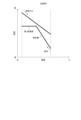
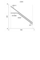
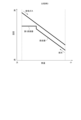
以上に説明した蒸気発生装置6により得られる効果について、図2~図5に示すTQ線図を用いて説明する。図2~図5は、蒸気発生装置における節炭器から第1蒸発器までの給水の熱量と温度の関係を示す線と、第1蒸発器から節炭器までの排気ガスの熱量と温度の関係を示す線とを示す図である。図2は、節炭器を1つだけ備えておりフラッシュタンクを備えていない蒸気発生装置(比較例1)に係る図である。図3は、節炭器を1つだけ備えておりフラッシュタンクを備えており第1蒸発器の入口の水をフラッシュタンクでフラッシュさせて理想的に最大の熱量を回収する蒸気発生装置(比較例2)に係る図である。図4は、節炭器を1つだけ備えておりフラッシュタンクを備えており、アプローチ温度差(第1蒸発器の圧力における飽和温度と第1蒸発器の入口の給水温度の差)が0でない蒸気発生装置(比較例3)に係る図である。図5は、第1節炭器、第2節炭器及びフラッシュタンクを備える上述した実施形態の蒸気発生装置6に係る図である。
The effects obtained by the
図2、図3及び図5に示す例では、熱利用効率を高くするために、アプローチ温度差が0となっており、蒸発器の入口の水が飽和水の場合(飽和温度で乾き度が0%の場合)が示されている。 In the examples shown in Figures 2, 3, and 5, the approach temperature difference is set to 0 in order to increase the heat utilization efficiency, and the water at the evaporator inlet is saturated water (saturation temperature and dryness fraction of 0%).
図2に示すように、比較例1では、フラッシュタンクが設けられていないため、排熱回収ボイラー5での熱回収量が少なく、排気ガスを温度が高いまま放出することになるので、熱利用効率が低い。
As shown in Figure 2, in Comparative Example 1, since a flash tank is not provided, the amount of heat recovered in the
また、図3に示すように、比較例2では、最も熱回収量を増大し、熱利用効率を増大する理想的な場合、給水を示す線の傾きが排気ガスの線と等しくなるようフラッシュ流量が設定される。このとき、熱回収量が大きく、節炭器における排気ガスと給水との温度差は入口から出口まで小さいので、高い熱利用効率を得ることができるが、節炭器が大型化してしまう。 As shown in Figure 3, in Comparative Example 2, in the ideal case of increasing the amount of heat recovered and increasing the heat utilization efficiency, the flush flow rate is set so that the slope of the line representing the feed water is equal to the line representing the exhaust gas. In this case, the amount of heat recovered is large and the temperature difference between the exhaust gas and the feed water in the economizer is small from the inlet to the outlet, so high heat utilization efficiency can be obtained, but the economizer becomes larger.
また、図4に示すように、比較例3では、給水を示す線の傾きが排気ガスの線と等しくなるようにフラッシュ流量が設定され、第1蒸発器の入口の給水温度を下げると節炭器の伝熱面積が過大となることを避けることができる。このとき、熱回収量は図5に示す場合と同等であるが、第1蒸発器で排気ガスから回収した熱の一部が給水の第1蒸発器入口温度から第1蒸発器の圧力における飽和温度までの昇温に使われてしまうため、蒸発に利用可能な熱量が減少し、第1蒸発器の蒸気が減少する。このため、より低圧低温のフラッシュ蒸気の流量が増大する一方、フラッシュ蒸気よりも高圧高温で利用価値が高い第1蒸発器の蒸気が減少するため、図5に示す場合よりも熱利用効率が低下する。 As shown in FIG. 4, in Comparative Example 3, the flash flow rate is set so that the slope of the line showing the feedwater is equal to the line showing the exhaust gas, and it is possible to avoid the heat transfer area of the economizer becoming excessive when the feedwater temperature at the inlet of the first evaporator is lowered. In this case, the amount of heat recovered is the same as in the case shown in FIG. 5, but part of the heat recovered from the exhaust gas in the first evaporator is used to raise the temperature of the feedwater from the inlet temperature of the first evaporator to the saturation temperature at the pressure of the first evaporator, so the amount of heat available for evaporation decreases and the steam in the first evaporator decreases. As a result, the flow rate of the flash steam with a lower pressure and temperature increases, while the steam in the first evaporator, which has a higher utility value at a higher pressure and higher temperature than the flash steam, decreases, so the heat utilization efficiency decreases compared to the case shown in FIG. 5.
これに対し、図1及び図5に示す実施形態に係る蒸気発生装置6は、第1低圧節炭器22で加熱された水を第2低圧節炭器24に供給する給水ライン52と、加熱水ライン52から分岐して設けられ、第1低圧節炭器22で加熱された水をフラッシュタンク8に供給する給水ライン53と、を備えるため、第2低圧節炭器24の流量が第1低圧節炭器22の流量よりも少なくなる(図5で、第2低圧節炭器の給水の線の傾きが第1低圧節炭器の給水の線の傾きより大きくなる)。このため、フラッシュタンク8に供給する給水の流量に応じて第1低圧節炭器22の給水の流量が多くなっても、比較的小さな第2低圧節炭器24で給水の温度を高効率に飽和蒸気温度に近づけることができる。また、第1低圧節炭器22では排気ガスと給水の温度差が比較的大きいので、給水の流量が多くなっても比較的小さなサイズとすることができる。したがって、1つの節炭器で給水の温度を飽和蒸気温度に近づける場合と比較して、節炭器のサイズ(第1低圧節炭器22のサイズと第2低圧節炭器24のサイズの合計)の大型化を抑制しつつ、フラッシュタンク8を用いて熱媒体の熱利用の効率を高めることができる。
In contrast, the
<コンバインドプラント2の変形例>
次に、図6~図12を用いて、コンバインドプラント2の変形例を説明する。
図6~図12に示す幾つかの実施形態に係るコンバインドプラント2(2A~2F)において、図1に示したコンバインドプラント2の各構成と共通の符号は、特記しない限り図1に示した蒸気発生装置の各構成と同様の構成を示すものとし、説明を省略する。
<Modification of
Next, modified examples of the combined
In the combined plants 2 (2A to 2F) according to some embodiments shown in FIGS. 6 to 12 , the reference symbols common to the respective components of the combined
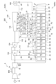
図6は、他の実施形態に係るコンバインドプラント2(2B)の概略的な全体構成を示す図である。図7は、他の実施形態に係るコンバインドプラント2(2C)の概略的な全体構成を示す図である。 Figure 6 is a diagram showing a schematic overall configuration of a combined plant 2 (2B) according to another embodiment. Figure 7 is a diagram showing a schematic overall configuration of a combined plant 2 (2C) according to another embodiment.
幾つかの実施形態では、例えば図6及び図7に示すように、コンバインドプラント2(2B,2C)の蒸気発生装置6(6B,6C)は、第2低圧節炭器24で加熱された水をフラッシュタンク8に供給するための給水ライン63を更に備える。給水ライン63は、給水ライン54から分岐して給水ライン53に合流する。
In some embodiments, as shown in, for example, FIG. 6 and FIG. 7, the steam generator 6 (6B, 6C) of the combined plant 2 (2B, 2C) further includes a
これにより、第2低圧節炭器24の流量を調節することができ、適度のサイズの節炭器で高い効率を得ることができる。また、低圧蒸発器26の蒸発量に影響し、特に重要な第2低圧節炭器24の出口の給水温度を高く(低圧蒸発器26のアプローチ温度差を0に近く)保ちつつ、第1節炭器22における排気ガスと給水の温度差を第1節炭器22の給水出口よりも大きな一定の値に保つことができる。ここで、排気ガスと給水との温度差は、一定の場合がサイズの割に最も熱交換量が大きいため、第1節炭器22のサイズを合理的に小型化しつつ、性能上特に重要な第2低圧節炭器24のみ大型化して効率を高めることができる。
This allows the flow rate of the second low-
幾つかの実施形態では、例えば図7に示すように、コンバインドプラント2(2C)の蒸気発生装置6(6C)は、フラッシュタンク8で発生した蒸気を過熱するための過熱器69を更に備える。過熱器69は、給水ライン63を流れる加熱水と蒸気ライン57を流れる蒸気とを熱交換させることにより、蒸気ライン57を流れる蒸気を過熱する。他の実施形態では、図6に示すように、給水ライン63を流れる加熱水を過熱器69を経ずにフラッシュタンク8に直接供給してもよい。
In some embodiments, for example as shown in FIG. 7, the steam generator 6 (6C) of the combined plant 2 (2C) further includes a
図7に示すように、給水ライン63を流れる高温の給水を利用して蒸気ライン57を流れる蒸気を過熱器69で過熱することにより、過熱しない場合よりも高い温度の蒸気を利用することができ、熱利用効率を高めることができる。また、蒸気を過熱状態とすることにより、蒸気ライン57等の配管内での凝縮を抑制し、ドレン水による配管の閉塞等のトラブルを抑制することができる。また、過熱器69から出た蒸気を蒸気タービンで用いる場合、蒸気タービンの下流段の湿り度を低減し、タービン翼のエロージョンを抑制するとともに、蒸気タービンの効率を高めることができる。特に、複数個所から取得した給水を利用してフランシュ蒸気を生成することにより、温度の低い水がフラッシュして生成された蒸気も温度の高い給水で過熱することができるので、高い温度の加熱蒸気を大量に生成することができる。
As shown in FIG. 7, by using the high-temperature feed water flowing through the
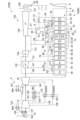
幾つかの実施形態では、例えば図8に示すように、コンバインドプラント2(2D)の蒸気発生装置6(6D)は、低温熱交換器23及び第3低圧節炭器25を更に備える。図8に示す形態では、復水器108と低温熱交換器23とが、給水ライン21によって接続されており、給水ライン21には復水器108から出た復水を低温熱交換器23に供給するための復水ポンプ50が設けられている。
In some embodiments, as shown in FIG. 8, for example, the steam generator 6 (6D) of the combined plant 2 (2D) further includes a low-
低温熱交換器23は、給水ライン21から供給された水を排気ガスとの熱交換により加熱する。低温熱交換器23で加熱された水は、低温熱交換器23と第1低圧節炭器22とを接続する給水ライン29を介して第1低圧節炭器22へ供給される。低温熱交換器23では、水と熱交換することにより、排気ガスの温度が低下し、排気ガス中の水分の一部が凝縮し、放出される潜熱の一部も水に回収することができ、熱利用効率を高めることができる。低温熱交換器23は凝縮水による腐食を防止するため、耐腐食性の高いステンレス鋼等の材料で製作されている。
The low-
第1低圧節炭器22は、給水ライン29から供給された水を排気ガスとの熱交換により加熱する。第1低圧節炭器22で加熱された水の一部は、第1低圧節炭器22と第2低圧節炭器24とを接続する給水ライン52を介して第2低圧節炭器24へ供給される。
The first low-
第2低圧節炭器24で加熱された水の一部は、第2低圧節炭器24と第3低圧節炭器25とを接続する給水ライン27を介して第3低圧節炭器25に供給される。
A portion of the water heated in the second low-
第3低圧節炭器25は、第2低圧節炭器24から給水ライン27を介して供給された水を排気ガスとの熱交換により加熱する。第3低圧節炭器25で加熱された水の一部は、第3低圧節炭器25と低圧蒸発器26とを接続する給水ライン54を介して低圧蒸発器26へ供給される。
The third low-
低圧蒸発器26は、第3低圧節炭器25から給水ライン54を介して供給された水を排気ガスとの熱交換により加熱して蒸発させ、低圧蒸気を生成する。給水ライン54には、第3低圧節炭器25から供給された水を減圧するための給水弁55が設けられている。低圧蒸発器26で生成された低圧蒸気の一部は、低圧蒸発器26と低圧過熱器28とを接続する蒸気ライン56を介して低圧過熱器28へ供給される。
The low-
第3低圧節炭器25で加熱された水の一部は、給水ライン60を介して中圧節炭器31に供給される。給水ライン60は、給水ライン54から分岐して中圧節炭器31に接続しており、給水ライン60を流れる加熱水は、給水ライン60に設けられた中圧給水ポンプ62によって中圧節炭器31に圧送される。
A portion of the water heated in the third low-
中圧節炭器31は、第3低圧節炭器25から給水ライン60を介して供給された水を排気ガスとの熱交換により加熱する。中圧節炭器31で加熱された水は、中圧節炭器31と中圧蒸発器32とを接続する給水ライン64を介して中圧蒸発器32に供給される。
The
図8に示す形態では、コンバインドプラント2(2D)の蒸気発生装置6(6D)は、互いに異なる圧力に設定された複数のフラッシュタンク8a~8dと、複数のフラッシュタンク8a~8dを直列に接続し、フラッシュタンク8a~8dの各々から排出されたドレン水を導くドレン水ライン71と、排熱回収ボイラー5で排気ガスによって加熱された水をドレン水ライン71に供給する複数の給水ライン73,75,77を備える。給水ライン73は、給水ライン54から分岐してフラッシュタンク8aに接続する。給水ライン75は、給水ライン27から分岐してドレン水ライン71におけるフラッシュタンク8aとフラッシュタンク8bとの間の位置に合流する。給水ライン77は、給水ライン52から分岐してドレン水ライン71におけるフラッシュタンク8bとフラッシュタンク8cとの間の位置に合流する。
In the embodiment shown in FIG. 8, the steam generator 6 (6D) of the combined plant 2 (2D) includes a plurality of
給水ライン73には減圧弁84が設けられている。ドレン水ライン71におけるフラッシュタンク8aとフラッシュタンク8bとの間の位置には減圧弁85が設けられている。ドレン水ライン71におけるフラッシュタンク8bとフラッシュタンク8cとの間の位置には減圧弁86が設けられている。ドレン水ライン71におけるフラッシュタンク8cとフラッシュタンク8dとの間の位置には減圧弁87が設けられている。
The
給水ライン73から分岐した給水ライン79は、ドレン水ライン71におけるフラッシュタンク8cとフラッシュタンク8dとの間の位置に接続する。給水ライン79には、複数の過熱器88,89,90,91が設けられている。
The
フラッシュタンク8aは、給水ライン73から供給された加熱水を減圧し蒸発させて(フラッシュさせて)フラッシュ蒸気を生成する。フラッシュタンク8aで生成されたフラッシュ蒸気は、フラッシュタンク8aと中圧排気ライン110とを接続する蒸気ライン92を介して中圧排気ライン110に流入し、中圧排気ライン110を介して低圧蒸気タービン106の蒸気入口に流入する。蒸気ライン92には過熱器88が設けられており、蒸気ライン92を流れる蒸気は、過熱器88で給水ライン79を流れる加熱水との熱交換によって過熱されてから低圧蒸気タービン106へ供給される。
The
フラッシュタンク8bは、フラッシュタンク8aから排出されたドレン水及び給水ライン75から供給された加熱水を減圧し蒸発させて(フラッシュさせて)フラッシュ蒸気を生成する。フラッシュタンク8bで生成されたフラッシュ蒸気は、フラッシュタンク8bと低圧蒸気タービン106の中間段落とを接続する蒸気ライン93を介して低圧蒸気タービン106に流入する。蒸気ライン93には過熱器89が設けられており、蒸気ライン93を流れる蒸気は、過熱器89で給水ライン79を流れる加熱水との熱交換によって過熱されてから低圧蒸気タービン106へ供給される。
The
フラッシュタンク8cは、フラッシュタンク8bから排出されたドレン水及び給水ライン77から供給された加熱水を減圧し蒸発させて(フラッシュさせて)フラッシュ蒸気を生成する。フラッシュタンク8cで生成されたフラッシュ蒸気は、フラッシュタンク8cと低圧蒸気タービン106の中間段落とを接続する蒸気ライン94を介して低圧蒸気タービン106に流入する。蒸気ライン94には過熱器90が設けられており、蒸気ライン94を流れる蒸気は、過熱器90で給水ライン79を流れる加熱水との熱交換によって過熱されてから低圧蒸気タービン106へ供給される。
The
フラッシュタンク8dは、フラッシュタンク8cから排出されたドレン水及び給水ライン79から供給された加熱水を減圧し蒸発させて(フラッシュさせて)フラッシュ蒸気を生成する。フラッシュタンク8dで生成されたフラッシュ蒸気は、フラッシュタンク8dと低圧蒸気タービン106の中間段落とを接続する蒸気ライン95を介して低圧蒸気タービン106に流入する。蒸気ライン95には過熱器91が設けられており、蒸気ライン95を流れる蒸気は、過熱器91で給水ライン79を流れる加熱水との熱交換によって過熱されてから低圧蒸気タービン106へ供給される。
The
ここで、低圧蒸気タービン106における蒸気の流れ方向において、蒸気ライン93が低圧蒸気タービン106に接続する位置は、中圧排気ライン110が低圧蒸気タービン106に接続する位置よりも下流側であり、蒸気ライン94が低圧蒸気タービン106に接続する位置は、蒸気ライン93が低圧蒸気タービン106に接続する位置よりも下流側であり、蒸気ライン95が低圧蒸気タービン106に接続する位置は、蒸気ライン94が低圧蒸気タービン106に接続する位置よりも下流側である。
Here, in the direction of steam flow in the low-
ここで、給水ライン75を流れる水の温度Tw1は、複数のフラッシュタンク8a~8dのうちドレン水ライン71の流れ方向においてドレン水ライン71と給水ライン75とが接続する位置P1よりも上流側に位置するフラッシュタンク8aの圧力Paに応じた飽和温度Taよりも低い。また、給水ライン75を流れる水の温度Tw1は、複数のフラッシュタンク8a~8dのうちドレン水ライン71の流れ方向においてドレン水ライン71と給水ライン75とが接続する位置P1よりも下流側に位置するフラッシュタンク8bの圧力Pbに応じた飽和温度Tbよりも高い。
Here, the temperature Tw1 of the water flowing through the
また、給水ライン77を流れる水の温度Tw2は、複数のフラッシュタンク8a~8dのうちドレン水ライン71の流れ方向においてドレン水ライン71と給水ライン77とが接続する位置P2よりも上流側に位置するフラッシュタンク8bの圧力に応じた飽和温度よりも低い。また、給水ライン77を流れる水の温度は、複数のフラッシュタンク8a~8dのうちドレン水ライン71の流れ方向においてドレン水ライン71と給水ライン77とが接続する位置P2よりも下流側に位置するフラッシュタンク8cの圧力に応じた飽和温度よりも高い。
The temperature Tw2 of the water flowing through the
このように、給水ライン75の水の温度をTw1、給水ライン75の水の温度をTw2、フラッシュタンク8aにおける蒸気の圧力Paに対応する蒸気の飽和温度をTa、フラッシュタンク8bにおける蒸気の圧力Pbに対応する蒸気の飽和温度をTb、フラッシュタンク8cにおける蒸気の圧力Pcに対応する蒸気の飽和温度をTc、フラッシュタンク8dにおける蒸気の圧力Pdに対応する蒸気の飽和温度をTdと定義すると、Ta>Tw1>Tb>Tw2>Tc>Tdを満たす。
In this way, if we define the temperature of the water in the
図8に示す構成によれば、互いに圧力の異なる複数のフラッシュタンク8a~8dが設けられており、複数個所の給水がその温度に応じてドレン水ラインの適切な温度の箇所に投入されるため、熱利用効率を高めることができる。また、フラッシュタンク8a~8dの飽和水を、順次、圧力及び温度の低いフラッシュタンク8に送ってフラッシュさせることにより、熱を温度に応じて回収し、熱利用効率を高めることができる。
According to the configuration shown in FIG. 8,
幾つかの実施形態では、例えば図9に示すように、蒸気発生装置6(6B)は、複数の節炭器22,24のうち少なくとも1つの節炭器の出口から出た水の一部を熱源として利用するように構成される。図9に示す形態では、複数の節炭器22,24の出口から出た水の一部は、排熱回収ボイラー5の外部に設けられた熱交換器120,122に熱源として供給される。
In some embodiments, as shown in FIG. 9, for example, the steam generator 6 (6B) is configured to use a portion of the water exiting the outlet of at least one of the
給水ライン53から分岐した給水ラインKは、圧縮機12の入口に接続する吸気ラインに設けられた熱交換器120に接続されており、第1低圧節炭器22の出口から出た加熱水の一部は、給水ラインKを通って熱交換器120に供給され、熱交換器120で圧縮機12の吸気を熱交換により加熱する。給水ラインKを通って熱交換器120に供給された加熱水は、熱交換器120を通過後に、給水ラインLを通って復水器108に戻される。この場合の熱交換器120は熱利用設備の一種である。圧縮機12の吸気を加熱することにより、低大気温時や入口案内翼(IGV)の角度を絞った運転をする時に吸気中の水分の凝縮、氷結を防止する効果や、電力需要が少ない時間帯に低出力で運転することを可能とする効果を得ることができる。吸気の温度は高いときでも40℃前後であり、その加熱に、一般に140℃~180℃となる低圧蒸発器26(第1蒸発器)入口給水を用いると必要以上に高温の熱を使ってしまうこととなり、熱利用効率が低い。吸気の加熱に低圧蒸発器26(第1蒸発器)入口給水よりも低温の第1低圧節炭器22の出口から出た加熱水を用いることにより、低温の熱を有効に活用して吸気を加熱することができ、熱利用効率を高めることができる。100℃を超える温度の熱は常圧の水蒸気を発生させることができるのであり、100℃を超える温度の熱と100℃以下の熱では大きく利用価値が異なる。従って、140℃~180℃の低圧蒸発器26(第1蒸発器)入口給水を用いて、利用価値が低い100℃以下の熱を持つ被加熱媒体を加熱すると、熱の利用価値を大きく損なうことになるのである。逆に、低圧蒸発器26(第1蒸発器)入口給水よりも温度が低い、第1低圧節炭器22の出口の加熱水を用いて、100℃以下の被加熱媒体を加熱すると、熱の利用価値を大きく損なうことなく、熱利用効率を向上することができる。
The water supply line K branched off from the
給水ライン63から分岐した給水ラインMは、燃焼器14に燃料を供給する燃料供給ラインに設けられた熱交換器122に接続されており、第2低圧節炭器24の出口から出た加熱水の一部は、給水ラインMを通って熱交換器122に供給され、熱交換器122で燃焼器14に供給される燃料を熱交換により加熱する。給水ラインMを通って熱交換器122に供給された加熱水は、熱交換器122を通過後に、給水ラインNを通って凝縮水ライン51に流入する。以上のように、熱交換器120、122に、それぞれ必要とされる温度に近い温度の節炭器出口の加熱水を適宜選択して利用することにより、熱利用効率を高めることができる。
The water supply line M branching off from the
幾つかの実施形態では、例えば図9に示すように、蒸気発生装置6(6B)は、複数の節炭器22,24のうち少なくとも1つの節炭器の入口に水を供給するラインを流れる水の一部を冷却媒体として利用し、排熱を回収するように構成される。図9に示す形態では、節炭器22の入口に接続するライン48,53を流れる水の一部は、排熱回収ボイラー5の外部に設けられた熱交換器124,126,128,129,130,132に冷却媒体として供給される。
In some embodiments, as shown in FIG. 9, the steam generator 6 (6B) is configured to recover exhaust heat by using a portion of the water flowing through a line that supplies water to the inlet of at least one of the
給水ライン70から分岐した給水ラインAは、熱交換器124に接続されている。熱交換器124は、圧縮機12で圧縮された空気の一部を冷却用空気として燃焼器14に供給する冷却用空気ライン134に設けられており、第2低圧節炭器24を出た水の一部は、給水ラインAを通って熱交換器124に供給され、熱交換器124で冷却用空気を熱交換により冷却する。給水ラインAを通って熱交換器124に供給された加熱水は、熱交換器124を通過後に、給水ラインBを通って給水ライン76に流入する。
The water supply line A branched off from the
給水ライン48から分岐した給水ラインCは、発電機19の冷却媒体を冷却するための冷却媒体クーラー126に接続されている。給水ライン48を流れる水の一部は、給水ラインCを通って冷却媒体クーラー126に供給され、冷却媒体クーラー126で冷却媒体を熱交換により冷却する。給水ラインCを通って冷却媒体クーラー126に供給された水は、圧縮機12の軸受127に使用される潤滑油を冷却するための潤滑油クーラー128に供給されて、潤滑油を熱交換により冷却する。冷却媒体クーラー126に供給された水は、冷却媒体クーラーを通過後に、給水ラインDを通って給水ライン48に戻り、第1低圧節炭器22に流入する。
The water supply line C branched off from the
給水ライン48から分岐した給水ラインEは、熱交換器129に接続されている。熱交換器129は、圧縮機12から抽気した空気をタービン16に供給する抽気ライン138に設けられており、給水ライン48を流れる水の一部は、給水ラインEを通って熱交換器129に供給され、熱交換器129で圧縮機12から抽気した空気を熱交換により冷却する。給水ラインEから熱交換器129に供給された水は、給水ラインFを通って給水ライン52に流入する。
The water supply line E branching off from the
給水ライン48から分岐した給水ラインGは、熱交換器130に接続されている。熱交換器130は、冷却用空気ライン134における熱交換器124の下流側に設けられており、給水ライン48を流れる水の一部は、給水ラインGを通って熱交換器130に供給され、熱交換器130で冷却用空気を熱交換により冷却する。給水ラインGを通って熱交換器130に供給された加熱水は、熱交換器130を通過後に、給水ラインHを通って給水ライン52に流入する。なお、冷却用空気ライン134における熱交換器130の下流側には冷却空気を圧縮する圧縮機140が設けられている。
The water supply line G branched off from the
給水ライン53から分岐した給水ラインIは、熱交換器132に接続されている。熱交換器132は、圧縮機12における抽気ライン138が接続する位置よりも下流側から抽気した空気をタービン16に供給する抽気ライン136に設けられており、給水ライン53を流れる水の一部は、給水ラインIを通って熱交換器132に供給され、熱交換器132で圧縮機から抽気した空気を熱交換により冷却する。給水ラインIから熱交換器132に供給された水は、給水ラインJを通って給水ライン54に流入する。
The water supply line I branching off from the
このように、複数の節炭器22,24のうち少なくとも1つの節炭器の出口から出た水の一部を熱源として利用することにより、コンバインドプラント2全体での熱利用効率を高めることができる。
In this way, by using a portion of the water exiting the outlet of at least one of the
また、複数の節炭器22,24のうち少なくとも1つの節炭器の入口に水を供給するラインを流れる水の一部を冷却媒体として利用して排熱を回収することにより、コンバインドプラント2全体での熱利用効率を高めることができる。
In addition, by using a portion of the water flowing through a line that supplies water to the inlet of at least one of the
なお、図9に示すように様々な温度で低温排熱の利用や低温排熱の回収を行う場合、給水ライン48及び給水ライン52,53,63の給水の流量が温度レベルによって変わり、第1低圧節炭器22及び第2低圧節炭器24を流れる給水の流量が変化することとなり、TQ線図(例えば図5参照)の傾きが低圧節炭器のサイズ低減の観点から好ましいものとはならない。ここで、フラッシュに用いる水の量を温度レベル毎に例えば減圧弁59を用いて調整し、第1低圧節炭器22及び第2低圧節炭器24を流れる給水の流量を調整することにより、第1低圧節炭器22を流れる給水のTQ線図の傾きが、排気ガスのTQ線図の傾きに近くなるようにすると共に、第2低圧節炭器24の給水出口温度を低圧蒸発器26(第1蒸発器)の作動圧力における飽和温度に近付ける(アプローチ温度差を0に近付ける)ことにより、比較的サイズの小さな節炭器22,24で高い効率を得ることができる。
When low-temperature exhaust heat is utilized or recovered at various temperatures as shown in Figure 9, the flow rate of the water supply in the
幾つかの実施形態では、図9を用いて説明したコンバインドプラント2(2B)における給水を熱源又は冷却媒体として利用するための構成は、図10に示すように、上述した複数のフラッシュタンク8a~8d(多段フラッシュ)を備えるコンバインドプラント2(2D)に適用してもよい。図10に示すように、多段フラッシュの構成を採用して、給水を近い飽和温度の箇所に回収してフラッシュさせると、更に高い効率を得ることができる。この場合、熱源又は冷却媒体として用いる給水はそれぞれ、復水器108と低温熱交換器23とを接続する給水ライン21、各熱交換器20の間、即ち、低温熱交換器23の給水出口、第1低圧節炭器22の給水出口、第2低圧節炭器24の給水出口、第3低圧節炭器25の給水出口(低圧蒸発器26(第1蒸発器)の給水入口)の内、所望の温度の個所から取得し、使用後の給水は上記の各箇所の内、最も温度が近い箇所に回収すると熱利用効率を高めることができ、好ましい。
In some embodiments, the configuration for using the feedwater in the combined plant 2 (2B) described using FIG. 9 as a heat source or cooling medium may be applied to the combined plant 2 (2D) equipped with the above-mentioned
図10に対応するTQ線図を図13に示す。本図において、給水は右側から供給され、低温熱交換器(図10中の23)、第1低圧節炭器(図10中の22、第3節炭器)、第2低圧節炭器(図10中の24、第1節炭器)、第3低圧節炭器(図10中の25、第2節炭器)をこの順に経由して加熱され、給水を第3低圧節炭器(図10中の25、第2節炭器)から、熱媒体(排気ガス)と熱交換させることなく、低圧蒸発器26(第1蒸発器)に供給するように構成された給水ライン54(第6給水ライン)を通って、低圧蒸発器(図10中の26、第1蒸発器)に供給される。低温熱交換器(図10中の23)には給水が供給される。給水取得ラインEは、低温熱交換器(図10中の23)を出た給水の一部を、被冷却媒体である冷却空気を冷却する熱利用設備である冷却空気クーラー129の冷熱源となる給水として取得する。また、低温熱交換器(図10中の23)を出て、第1低圧節炭器(図10中の22、第3節炭器)に供給される給水にはフラッシュタンク8dからの凝縮水が、凝縮水ライン(給水供給ライン)51、給水ポンプ61を経由して混合される。
The TQ diagram corresponding to FIG. 10 is shown in FIG. 13. In this figure, the feed water is supplied from the right side, heated by passing through the low-temperature heat exchanger (23 in FIG. 10), the first low-pressure economizer (22 in FIG. 10, third economizer), the second low-pressure economizer (24 in FIG. 10, first economizer), and the third low-pressure economizer (25 in FIG. 10, second economizer) in this order, and is supplied to the low-pressure evaporator (26 in FIG. 10, first evaporator) through the water supply line 54 (sixth water supply line) configured to supply the water to the low-pressure evaporator 26 (first evaporator) from the third low-pressure economizer (25 in FIG. 10, second economizer) without exchanging heat with the heat medium (exhaust gas). The low-temperature heat exchanger (23 in FIG. 10) is supplied with water. The feedwater acquisition line E acquires a portion of the feedwater that leaves the low-temperature heat exchanger (23 in FIG. 10) as feedwater that serves as a cold heat source for the cooling
本実施形態では、低温熱交換器(図10中の23)出口の水よりも、凝縮水の方が温度が高いため、TQ線図上(図13)で、低温熱交換器(図10中の23)出口の給水よりも、第1低圧節炭器(図10中の22、第3節炭器)入口の給水の方が温度が高い。また、低温熱交換器(図10中の23)では、途中で排気ガス中の水分の一部が凝縮し、潜熱が放出されているため、排気ガス下流側の排気ガスのTQ線図の傾きが小さくなっている。また、第1低圧節炭器(図10中の22、第3節炭器)には、凝縮水が加わるため、低温熱交換器(図10中の23)よりも給水の流量が多く、第1低圧節炭器(図10中の22、第3節炭器)の給水のTQ線図の傾きは低温熱交換器(図10中の23)よりも小さい。 In this embodiment, the temperature of the condensed water is higher than that of the water at the outlet of the low-temperature heat exchanger (23 in FIG. 10), so on the TQ diagram (FIG. 13), the temperature of the feed water at the inlet of the first low-pressure economizer (22 in FIG. 10, the third economizer) is higher than that of the feed water at the outlet of the low-temperature heat exchanger (23 in FIG. 10). In addition, in the low-temperature heat exchanger (23 in FIG. 10), some of the moisture in the exhaust gas is condensed on the way and latent heat is released, so the slope of the TQ diagram of the exhaust gas downstream of the exhaust gas is smaller. In addition, since the first low-pressure economizer (22 in FIG. 10, the third economizer) is added with condensed water, the flow rate of the feed water is higher than that of the low-temperature heat exchanger (23 in FIG. 10), and the slope of the TQ diagram of the feed water of the first low-pressure economizer (22 in FIG. 10, the third economizer) is smaller than that of the low-temperature heat exchanger (23 in FIG. 10).
第1低圧節炭器(図10中の22、第3節炭器)出口の給水の一部は、給水取得ラインKによってガスタービン4の圧縮機12の吸気を加熱する熱利用設備である熱交換器120の熱源となる給水として取得されると共に、給水取得ラインGによって、ガスタービン4の燃焼器の冷却空気を冷却する冷却空気クーラー130の冷熱源となり、排熱を回収する給水として取得される。また、第1低圧節炭器(図10中の22、第3節炭器)出口の給水の一部は給水ライン(給水取得ライン)77によってフラッシュタンク8cに送られる。これらの水が取得されるため、第2低圧節炭器(図10中の24、第1節炭器)を流れる給水の流量は、第1低圧節炭器(図10中の22、第3節炭器)よりも少なく、第2低圧節炭器(図10中の24、第1節炭器)の給水のTQ線図の傾きは第1低圧節炭器(図10中の22、第3節炭器)よりも大きい。
A portion of the feed water at the outlet of the first low pressure economizer (22 in FIG. 10, third economizer) is obtained by feed water acquisition line K as feed water to be a heat source for
第2低圧節炭器(図10中の24、第1節炭器)出口、即ち、第3低圧節炭器(図10中の25、第2節炭器)入口の給水には、熱利用設備である冷却空気クーラー129、130で冷熱源として利用され、排熱を回収した給水が、給水供給ラインF、Hによって混合されると共に、給水取得ラインIによって、熱利用設備である冷却空気クーラー132の冷熱源として取得され、また、給水取得ラインMによって、熱利用設備である燃料予熱器122に熱源として供給される。本例では、給水供給ラインによって給水が混入されることにより、第3低圧節炭器(図10中の25、第2節炭器)入口の給水温度は、第2低圧節炭器(図10中の24、第1節炭器)出口の給水の温度よりもわずかに低い(図13)。ここで、冷却空気クーラー129および130よりも、冷却空気クーラー132の方が被冷却媒体である冷却空気の温度が高く、このため、被冷却媒体の温度が高い冷却空気クーラー132には被冷却媒体の温度が低い冷却空気クーラー129、130よりも高い温度の給水を冷熱源として供給する。こうすることによって、冷却空気クーラー、即ち、熱利用設備の排熱をより近い温度の冷却媒体に回収して効果的に活用することができ、熱利用効率が高まる。
The feed water at the outlet of the second low-pressure economizer (24, first economizer in FIG. 10), i.e., the feed water at the inlet of the third low-pressure economizer (25, second economizer in FIG. 10), is used as a cold source in the cooling
以上のように、第2低圧節炭器(図10中の24、第1節炭器)出口、即ち、第3低圧節炭器(図10中の25、第2節炭器)入口の給水には、様々な給水取得ライン、給水供給ラインが設けられ、種々の給水が授受される。本実施形態では、第2低圧節炭器(図10中の24、第1節炭器)出口、即ち、第3低圧節炭器(図10中の25、第2節炭器)入口から取得される給水の量は、供給される給水の量よりも多くなるように構成されている。従って、第3低圧節炭器(図10中の25、第2節炭器)に流れる給水の質量流量は、第2低圧節炭器(図10中の24、第1節炭器)に流れる給水の質量流量よりも少なく、第3低圧節炭器(図10中の25、第2節炭器)のTQ線図の傾きは、第2低圧節炭器(図10中の24、第1節炭器)のTQ線図の傾きよりも大きい(図13)。このようなTQ線図の傾きを実現することにより、第2低圧節炭器(図10中の24、第1節炭器)において、給水のTQ線図の傾きが排気ガスのTQ線図の傾きに近くなり、排気ガス‐給水の温度差を一定に近い適度の温度差に保つことができる。 As described above, various feedwater acquisition lines and feedwater supply lines are provided for the water supply at the outlet of the second low-pressure economizer (24 in FIG. 10, first economizer), i.e., the inlet of the third low-pressure economizer (25 in FIG. 10, second economizer), and various feedwaters are exchanged. In this embodiment, the amount of feedwater acquired from the outlet of the second low-pressure economizer (24 in FIG. 10, first economizer), i.e., the inlet of the third low-pressure economizer (25 in FIG. 10, second economizer), is configured to be greater than the amount of feedwater supplied. Therefore, the mass flow rate of the feedwater flowing to the third low pressure economizer (25 in FIG. 10, second economizer) is less than the mass flow rate of the feedwater flowing to the second low pressure economizer (24 in FIG. 10, first economizer), and the slope of the TQ diagram of the third low pressure economizer (25 in FIG. 10, second economizer) is greater than the slope of the TQ diagram of the second low pressure economizer (24 in FIG. 10, first economizer) (FIG. 13). By realizing such a slope of the TQ diagram, the slope of the TQ diagram of the feedwater becomes closer to the slope of the TQ diagram of the exhaust gas in the second low pressure economizer (24 in FIG. 10, first economizer), and the temperature difference between the exhaust gas and the feedwater can be maintained at a moderate temperature difference that is close to constant.
また、第3低圧節炭器(図10中の25、第2節炭器)の流量が少なく、TQ線図の傾きが大きいことにより、第3低圧節炭器(図10中の25、第2節炭器)は低圧蒸発器26(第1蒸発器)に低圧蒸発器26(第1蒸発器)の蒸気圧力に対応する飽和温度(図13中、水平の線)に近い温度の水を供給することができると同時に、熱媒体の流れから見て下流側に配置される熱交換器(節炭器)では排気ガス(熱媒体)‐給水の温度差を十分に確保することができる。従って、比較的高い熱利用効率をサイズの小さな熱交換器(節炭器)で実現することができる。 In addition, because the flow rate of the third low-pressure economizer (25 in FIG. 10, second economizer) is small and the slope of the TQ diagram is large, the third low-pressure economizer (25 in FIG. 10, second economizer) can supply water to the low-pressure evaporator 26 (first evaporator) at a temperature close to the saturation temperature (horizontal line in FIG. 13) corresponding to the steam pressure of the low-pressure evaporator 26 (first evaporator), while at the same time ensuring a sufficient temperature difference between the exhaust gas (heat medium) and the feed water in the heat exchanger (economiter) located downstream in terms of the flow of the heat medium. Therefore, a relatively high heat utilization efficiency can be achieved with a small-sized heat exchanger (economiter).
また、第3低圧節炭器(図10中の25、第2節炭器)に流れる給水の質量流量が、第1低圧節炭器(図10中の22、第3節炭器)に流れる給水の質量流量よりも少なく、第3低圧節炭器(図10中の25、第2節炭器)の給水のTQ線図の傾きが、第1低圧節炭器(図10中の22、第3節炭器)の給水のTQ線図の傾きよりも大きいことが、より好ましい。このような構成を備えると、熱媒体(排気ガス)から見て下流側まで、排気ガス‐給水の温度差を一定に近い適度の温度差に保つことができ、よりサイズの小さな熱交換器(節炭器)で、高い熱利用効率を得ることができる。また、第3低圧節炭器(図10中の25、第2節炭器)の給水の流量が、熱媒体(排気ガス)から見て下流側の全ての節炭器(熱交換器)よりも少ないことがより一層好ましい。この場合、一層サイズの小さな熱交換器(節炭器)で、高い熱利用効率を得ることができる。 It is more preferable that the mass flow rate of the feedwater flowing to the third low-pressure economizer (25 in FIG. 10, second economizer) is less than the mass flow rate of the feedwater flowing to the first low-pressure economizer (22 in FIG. 10, third economizer), and that the slope of the TQ diagram of the feedwater of the third low-pressure economizer (25 in FIG. 10, second economizer) is greater than the slope of the TQ diagram of the feedwater of the first low-pressure economizer (22 in FIG. 10, third economizer). With such a configuration, the temperature difference between the exhaust gas and the feedwater can be kept at a moderate temperature difference close to a constant level up to the downstream side as viewed from the heat medium (exhaust gas), and high heat utilization efficiency can be obtained with a smaller-sized heat exchanger (economiser). It is even more preferable that the flow rate of the feedwater of the third low-pressure economizer (25 in FIG. 10, second economizer) is less than all economizers (heat exchangers) downstream as viewed from the heat medium (exhaust gas). In this case, high heat utilization efficiency can be achieved with a small heat exchanger (save unit) of one layer.
また、以上の説明の通り、熱媒体(排気ガス)流路おける熱媒体の流れ方向において、低圧蒸発器(26、第1蒸発器)よりも下流側に、第2低圧節炭器(図10中の24、第1節炭器)と第3低圧節炭器(図10中の25、第2節炭器)とを含む複数の節炭器を含み、複数の節炭器の内1つの節炭器の出口から出た水の一部を取得する給水取得ライン、または、複数の節炭器の内1つの節炭器の入口に給水を供給する給水供給ラインの内、少なくとも一方を備えると、給水を取得、または、供給することにより、前後の節炭器の給水流量を調整し、上記のように好ましいTQ線図の傾きを実現、比較的高い熱利用効率をサイズの小さな熱交換器(節炭器)で実現することができる。特に、それぞれ、異なる節炭器の出口から出た水の一部を取得する2つ以上の給水取得ライン、それぞれ、異なる節炭器の入口に給水を供給する2つ以上の給水供給ラインの内、少なくとも一方を備えると、給水を利用する熱利用設備での利用に適した、適度の温度の個所から給水を取得し、または、近い温度の個所に給水を供給することができるので、熱利用効率を高め、プラントの効率を向上することができる。また、給水取得ラインと給水供給ラインの両方を備えると、更に効果的に、熱利用効率を高め、プラントの効率を向上することができる。 As explained above, in the flow direction of the heat medium in the heat medium (exhaust gas) flow path, multiple economizers including a second low-pressure economizer (24 in Figure 10, first economizer) and a third low-pressure economizer (25 in Figure 10, second economizer) are included downstream of the low-pressure evaporator (26, first evaporator), and at least one of a feedwater acquisition line that acquires a portion of the water discharged from the outlet of one of the multiple economizers, or a feedwater supply line that supplies feedwater to the inlet of one of the multiple economizers is provided. By acquiring or supplying feedwater, the feedwater flow rates of the preceding and following economizers can be adjusted, and a preferable slope of the TQ diagram as described above can be achieved, and a relatively high heat utilization efficiency can be achieved with a small-sized heat exchanger (economist). In particular, by providing at least one of two or more feedwater acquisition lines that each acquire a portion of the water coming out of the outlets of different economizers, and two or more feedwater supply lines that each supply feedwater to the inlets of different economizers, it is possible to acquire feedwater from a location with a suitable temperature suitable for use in the heat utilization equipment that uses the feedwater, or to supply feedwater to a location with a similar temperature, thereby improving the heat utilization efficiency and improving the efficiency of the plant. Furthermore, by providing both a feedwater acquisition line and a feedwater supply line, it is possible to more effectively increase the heat utilization efficiency and improve the efficiency of the plant.
また、給水供給ラインは、その給水入口に給水を供給する節炭器の給水出口よりも温度が低く、熱媒体(排気ガス)の流れ方向において、その給水入口に給水を供給する節炭器よりも下流に設置された節炭器の給水入口よりも温度が高い給水を供給することが好ましい。このような構成とすることにより、混合する個所の給水と、供給される給水の温度差を低減することができる。従って、その入口に給水を供給する節炭器の給水入口温度と、熱媒体(排気ガス)の流れ方向において下流側(給水の流れ方向において上流側)に給水ラインを接続して設置された節炭器の給水出口温度の温度差を低減できる。例えば、図10、図13の実施形態において、給水供給ラインF、Hが供給する給水の温度が、第3低圧節炭器(図10中の25、第2節炭器)の給水出口の温度よりも低く、第2低圧節炭器(図10中の24、第1節炭器)の給水入口温度よりも高いと、給水供給ラインF、Hが供給する給水の温度は第3低圧節炭器(図10中の25、第2節炭器)と第2低圧節炭器(図10中の24、第1節炭器)の間を流れる給水の温度に近く、第2低圧節炭器(図10中の24、第1節炭器)の給水出口と第3低圧節炭器(図10中の25、第2節炭器)の給水入口の温度差を低減することができる。 It is also preferable that the feedwater supply line supplies water that is lower in temperature than the feedwater outlet of the economizer that supplies feedwater to the feedwater inlet, and that is higher in temperature than the feedwater inlet of the economizer installed downstream of the economizer that supplies feedwater to the feedwater inlet in the flow direction of the heat transfer medium (exhaust gas). This configuration can reduce the temperature difference between the feedwater at the mixing point and the feedwater that is supplied. Therefore, it is possible to reduce the temperature difference between the feedwater inlet temperature of the economizer that supplies feedwater to the inlet, and the feedwater outlet temperature of the economizer that is installed with a feedwater line connected to it downstream in the flow direction of the heat transfer medium (exhaust gas) (upstream in the flow direction of the feedwater). For example, in the embodiment of FIG. 10 and FIG. 13, if the temperature of the feedwater supplied by the feedwater supply lines F and H is lower than the temperature of the feedwater outlet of the third low-pressure economizer (25 in FIG. 10, second economizer) and higher than the feedwater inlet temperature of the second low-pressure economizer (24 in FIG. 10, first economizer), the temperature of the feedwater supplied by the feedwater supply lines F and H is close to the temperature of the feedwater flowing between the third low-pressure economizer (25 in FIG. 10, second economizer) and the second low-pressure economizer (24 in FIG. 10, first economizer), and the temperature difference between the feedwater outlet of the second low-pressure economizer (24 in FIG. 10, first economizer) and the feedwater inlet of the third low-pressure economizer (25 in FIG. 10, second economizer) can be reduced.
従って、TQ線図(図13)において、第2低圧節炭器(図10中の24、第1節炭器)の給水に相当する線の左端(給水出口に相当)と第3低圧節炭器(図10中の25、第2節炭器)の給水に相当する線の右端(給水入口に相当)の温度差を低減することができ、第2低圧節炭器(図10中の24、第1節炭器)の給水出口と第3低圧節炭器(図10中の25、第2節炭器)の給水入口における熱媒体(排気ガス)‐給水の温度差を近い値とすることができるので、サイズの小さな熱交換器(節炭器)で、高い熱利用効率を得ることができる。 Therefore, in the TQ diagram (Figure 13), the temperature difference between the left end (corresponding to the feedwater outlet) of the line corresponding to the feedwater of the second low-pressure economizer (24 in Figure 10, first economizer) and the right end (corresponding to the feedwater inlet) of the line corresponding to the feedwater of the third low-pressure economizer (25 in Figure 10, second economizer) can be reduced, and the temperature difference between the heat medium (exhaust gas) and the feedwater at the feedwater outlet of the second low-pressure economizer (24 in Figure 10, first economizer) and the feedwater inlet of the third low-pressure economizer (25 in Figure 10, second economizer) can be made close to each other, so that a small-sized heat exchanger (economister) can achieve high heat utilization efficiency.
更に、第2低圧節炭器(図10中の24、第1節炭器)出口の給水の一部は給水ライン73を介してフラッシュタンク8bに送られ、減圧沸騰することにより発生した蒸気が低圧蒸気タービンの中間段に供給されて、動力を取り出す。更に第2低圧節炭器(図10中の24、第1節炭器)出口の給水の一部は低沸点媒体ランキンサイクル142に送られ、低沸点媒体ランキンサイクル142の内部を循環する低沸点媒体(例えば、ペンタン、シクロヘキサン、R245fa、等)を加熱する。加熱された低沸点媒体は蒸発し、タービンを駆動、動力を発生する。以上のように、フラッシュタンク8a~8dと低圧蒸気タービン106の組、低沸点媒体ランキンサイクル142は、排気ガス(熱媒体)が流れる熱媒体流路に設けられ、給水を加熱する複数の熱交換器(節炭器)の間の給水を取得する給水取得ラインの内、少なくともひとつから取得した給水を動力発生装置に送り、前記動力発生装置は、受け取った給水を用いて動力を発生する。
Furthermore, a portion of the feed water at the outlet of the second low pressure economizer (24 in FIG. 10, first economizer) is sent via
本構成により、給水の熱を有効に活用して動力を取り出すことができ、プラントの効率が高まる。その上で、減圧弁84、流量調整弁205、206を用いて、給水ライン(給水取得ライン)73、75、77の流量をそれぞれ調節し、第3低圧節炭器25の給水出口温度を低圧蒸発器26(第1蒸発器)の作動圧力における飽和温度に近付ける(アプローチ温度差を0に近付ける)と共に、第2低圧節炭器24、第3低圧節炭器25の流量を調節して第2低圧節炭器24、第3低圧節炭器25の給水のTQ線図の傾きが、それぞれ排気ガスのTQ線図の傾きに近くなるようにする。給水ライン(給水取得ライン)73、75、77の流量を増大すると、それぞれの分岐点の、給水から見て上流の節炭器、即ち、第3低圧節炭器25、第2低圧節炭器24、第1低圧節炭器22の給水流量が増大し、TQ線図の傾きが小さくなる。
This configuration makes it possible to effectively utilize the heat of the feedwater to extract power, improving plant efficiency. In addition, the flow rates of the feedwater lines (feedwater acquisition lines) 73, 75, and 77 are adjusted using the
逆に、それぞれのTQ線図の傾きを大きくするためには、給水ライン73、75、77の流量を減少させればよい。このようにして、第3低圧節炭器25給水出口(低圧蒸発器26の給水入口)の温度を低圧蒸発器26の作動圧力に対応する飽和温度に近付けると共に、第1低圧節炭器22、第2低圧節炭器24の給水のTQ線図の傾きを排気ガスのTQ線図の傾きに近付けることができ、比較的小さなサイズの節炭器で熱利用効率を高めることができる。なお、本実施形態の低沸点媒体ランキンサイクル142の構成は例であり、適宜、様々な構成の低沸点媒体ランキンサイクルを採用することができる。特開2015-183595に各種の構成が開示されているので、これを参照すれば、当業者は、様々な構成を適用することができるであろう。
Conversely, to increase the slope of each TQ diagram, the flow rate of the
動力発生装置を除く、ガスタービン4の吸気加熱器120、冷却空気クーラー129、130、132、燃料予熱器122等のプラント内の熱利用設備では、必要な熱源、冷熱源となる給水の流量は、加熱や冷却の必要性から決まっており、自由に設定することはできない。一方で、動力発生装置は適宜熱源となる給水の温度、流量を与えることができ、得られた給水の温度、流量に応じて動力を発生させることができる。そこで、本実施形態のように、動力発生装置を備えると、各種のプラント内の熱利用設備に必要な温度、流量の給水を供給する必要がある場合でも、動力発生装置に供給する給水の流量や、節炭器間の取得位置を変えることにより、前述のように複数の節炭器を流れる給水の流量分布を改善し、低圧蒸発器(第1蒸発器26)入口の給水温度を低圧蒸発器(第1蒸発器26)の蒸気圧力に対応する飽和温度に近付けると共に、各部の熱媒体(排気ガス)‐給水の温度差を適度の温度に保ち、サイズの小さな熱交換器(節炭器)で、高い熱利用効率を得ることができる。
In the heat utilization equipment in the plant, such as the
また、幾つかの実施形態では、図1に示すように、第2節炭器24で加熱された水の全量を低圧蒸発器26(第1蒸発器)、または、低圧蒸発器26(第1蒸発器)の蒸気圧力に応じた飽和温度よりも高い温度に加熱する高温熱交換器の内、少なくとも一方に送る。図1では、第2節炭器24で加熱された水は、全量が低圧蒸発器26(第1蒸発器)、中圧節炭器31、第1高圧節炭器30のいずれかに送られており、これ以外の熱利用設備には供給されない。中圧節炭器31、第1高圧節炭器30へは、それぞれ、中圧給水ポンプ62、高圧給水ポンプ72によって、給水が圧送される。中圧節炭器31、第1高圧節炭器30では、給水は昇圧されているため、低圧蒸発器26(第1蒸発器)の蒸気圧力に応じた飽和温度では沸騰せず、液相のまま、より高い温度まで加熱される。中圧節炭器31、第1高圧節炭器30で昇温された給水は、それぞれ、中圧蒸発器32、高圧蒸発器38で蒸発された後、最終的に、蒸気タービンを駆動し、動力を発生する。
In some embodiments, as shown in FIG. 1, the entire amount of water heated in the
低圧蒸発器26(第1蒸発器)に直接給水を送る第2節炭器24で加熱された給水を比較的低温の熱利用に用いる各種熱利用設備に送らず、低圧蒸発器26(第1蒸発器)、低圧蒸発器26(第1蒸発器)の蒸気圧力に応じた飽和温度よりも高い温度に加熱する中圧節炭器31、第1高圧節炭器30に限定して送ることにより、第2節炭器24で加熱される給水の流量を減少させることができる。これにより、節炭器を流れる給水の温度分布を前述の好ましい温度分布に近付け、TQ線図上で第2節炭器24の給水に相当する線の傾きを大きくし、低圧蒸発器26(第1蒸発器)に供給される給水の温度を低圧蒸発器26(第1蒸発器)の蒸気圧力に応じた飽和温度に近付け、熱利用効率を高めることができる。この場合、比較的低温の熱利用に用いる各種熱利用設備には、節炭器の間から比較的低温の給水を取得して送る(給水ライン53)。
The feedwater heated by the
また、幾つかの実施形態では、図10に示すように、ガスタービン4の圧縮機12出口の空気の一部がガスタービン4の燃焼器を冷却する冷却空気として取得される。この冷却空気は、当該冷却空気を燃焼器に送る圧縮機140の動力を低減すると共に、燃焼器を冷却する際の冷却効果を高めるために、熱交換器130で冷却、減温される。一方、第1低圧節炭器22出口の給水の一部が冷却媒体として、熱交換器130に供給される。熱交換器130には、前記冷却空気と、前記給水を熱交換することにより前記冷却空気を冷却すると共に前記給水を加熱する。即ち、熱交換器130は、給水を冷熱源として利用する熱利用設備である。また、冷却空気は被冷却媒体の一種である。
In some embodiments, as shown in FIG. 10, a portion of the air at the outlet of the
熱交換器130入口、出口における、前記冷却空気の温度は、それぞれ、例えば180℃、90℃で、熱交換器130入口、出口における、前記給水の温度はそれぞれ、80℃、130℃である。ここで、100℃を超える温度の熱は常圧の水蒸気を発生させることができるのであり、100℃を超える温度の熱と100℃以下の熱では大きく利用価値が異なる。従って、本例のように冷却空気減温の排熱を有効に活用して、100℃未満の節炭器出口の水を100℃よりも高い温度となるまで加熱すると、利用価値の高い熱を回収することができるのであり、特に熱利用効率を高めることができる。
The temperatures of the cooling air at the inlet and outlet of the
また、この場合、燃焼器において、十分な冷却効果を得るため、熱交換器130において、被冷却媒体である冷却空気を低圧蒸発器26(第1蒸発器)の蒸気圧力における飽和温度(例えば150℃)よりも低い温度まで冷却する必要がある。このとき、仮に熱交換器20が単一である場合を考えると、単一の熱交換器20の入口か出口の水を被冷却媒体の冷却に用いることになる。単一の熱交換器20では、給水出口の温度は低圧蒸発器26(第1蒸発器)の蒸気圧力における飽和温度に近い温度となるため、被冷却媒体を十分に低い温度まで冷却することはできず、熱交換器20の入口の給水を用いて冷却することとなる。従って、被冷却媒体を冷却する際の排熱を低温の給水に回収することとなり、排熱を有効に回収することができず、熱利用効率が低い。
In this case, in order to obtain a sufficient cooling effect in the combustor, it is necessary to cool the cooling air, which is the cooled medium, in the
従って、本開示のように、熱交換器20を複数設け、その途中から給水を取得して熱回収に利用すると、冷却媒体を低圧蒸発器26(第1蒸発器)の蒸気圧力における飽和温度(例えば150℃)よりも低い温度まで冷却する必要がある場合でも、排熱を適度の温度の給水に回収することができ、排熱を効率良く回収することができるのである。
Therefore, as disclosed herein, by providing
幾つかの実施形態では、例えば図11に示すように、低圧節炭器の数は1つでもよい。図11に示すコンバインドプラント2(2E)では、図7に示すコンバインドプラント2(2C)の第1低圧節炭器22及び第2低圧節炭器24に代えて、1つの低圧節炭器96が設けられている。
In some embodiments, the number of low pressure economizers may be one, for example as shown in FIG. 11. In the combined plant 2 (2E) shown in FIG. 11, one
図11に示す構成では、給水ライン48は復水器108と低圧節炭器96とを接続している。低圧節炭器96は、給水ライン48から供給された水を排気ガスとの熱交換により加熱する。低圧節炭器96で加熱された水の一部は、低圧節炭器96と低圧蒸発器26とを接続する給水ライン52を介して低圧蒸発器26へ供給される。
In the configuration shown in FIG. 11, the
また、低圧節炭器96で加熱された水の一部は、給水ライン60を介して中圧節炭器31に供給される。給水ライン60は、給水ライン54から分岐して中圧節炭器31に接続しており、給水ライン60を流れる加熱水は、給水ライン60に設けられた中圧給水ポンプ62によって中圧節炭器31に圧送される。
In addition, a portion of the water heated in the low-
フラッシュタンク8には、給水ライン52から分岐した給水ライン53が接続しており、低圧節炭器96で加熱された水の一部は、給水ライン53を介してフラッシュタンク8に供給される。給水ライン53には、低圧節炭器96から供給された加熱水を減圧するための減圧弁59が設けられている。給水ライン53を介してフラッシュタンク8に供給された加熱水は、フラッシュタンク8で減圧されて蒸発し(フラッシュし)、フラッシュ蒸気となる。フラッシュタンク8で生成されたフラッシュ蒸気は、フラッシュタンク8と低圧蒸気タービン106の中間段落とを接続する蒸気ライン57を介して低圧蒸気タービン106の中間段落に供給される。
A
フラッシュタンク8の底部に溜まった凝縮水は、フラッシュタンク8と給水ライン48とを接続する凝縮水ライン51を介して給水ライン48へ流入し、給水ライン48を介して低圧節炭器96に供給される。凝縮水ライン51には給水ポンプ61が設けられており、フラッシュタンク8から排出された凝縮水は給水ポンプ61により低圧節炭器96に圧送される。
The condensed water that accumulates at the bottom of the
このように、給水を1か所から取得し、フラッシュさせて発生したフラッシュ蒸気を、フラッシュさせる前の給水で過熱した場合においても、過熱しない場合よりも高い温度の蒸気を利用することができ、熱利用効率を高めることができる。また、蒸気を過熱状態とすることにより、蒸気ライン57等の配管内での凝縮を抑制し、ドレン水による配管の閉塞等のトラブルを抑制することができる。また、過熱器69から出た蒸気を蒸気タービンで用いる場合、蒸気タービンの下流段の湿り度を低減し、タービン翼のエロージョンを抑制するとともに、蒸気タービンの効率を高めることができる。
In this way, even if feed water is obtained from one location and the flash steam generated by flashing is superheated with the feed water before flashing, it is possible to use steam at a higher temperature than when it is not superheated, thereby improving the heat utilization efficiency. In addition, by superheating the steam, condensation in piping such as the
幾つかの実施形態では、例えば図12に示すように、コンバインドプラント2(2F)は、蒸気発生装置6で発生した蒸気を熱源として利用するコジェネレーションプラントとして構成されていてもよい。
In some embodiments, for example as shown in FIG. 12, the combined plant 2 (2F) may be configured as a cogeneration plant that uses steam generated in the
図12に示すコンバインドプラント2(2F)では、蒸気発生装置6から発生した蒸気、すなわち蒸気ライン58,92,93,94,95,117を流れる蒸気は、化学反応、食品加工、空調(蒸気を熱源とする暖房や吸収冷凍機の熱源として用いる冷房等)等の用途に利用してもよい。図12に示す例示的形態では、排熱回収ボイラー5の外部に熱交換器116が設けられており、第2高圧過熱器44で過熱された高圧過熱蒸気は、第2高圧過熱器44と熱交換器116とを接続する蒸気ライン117を通って熱交換器116に供給される。熱交換器116では、蒸気ライン117を介して供給された高圧過熱蒸気を上記用途に使用してもよい。熱交換器116で熱交換を行った高圧過熱蒸気は、バルブ119が設けられた蒸気ライン118を介して第1再熱器42に供給される。
In the combined plant 2 (2F) shown in FIG. 12, the steam generated from the
図10に示すコンバインドプラントでは、フラッシュタンク8a、8b、8cに、給水を供給する給水ライン73、75、77に、それぞれ、減圧弁84、流量調整弁205、206を備える。これらの各弁の開度を調整することにより、フラッシュタンク8a、8b、8cに供給される給水の流量を調整することができる。本構成によると、各熱交換器20(節炭器)の流量を調整することができるので、比較的高い熱利用効率を維持しつつ、熱交換器のサイズを小さくすることができる。以上のフラッシュタンクに供給する給水の流量を調整する構成は、図10のコンバインドプラントを例として図示、説明したが、他の実施形態にも適用することができる。
In the combined plant shown in FIG. 10, the
また、図10に示すコンバインドプラントでは、ドレン水ライン71におけるフラッシュタンク8aとフラッシュタンク8bとの間の位置には減圧弁85が設けられている。ドレン水ライン71におけるフラッシュタンク8bとフラッシュタンク8cとの間の位置には減圧弁86が設けられている。ドレン水ライン71におけるフラッシュタンク8cとフラッシュタンク8dとの間の位置には減圧弁87が設けられている。
In the combined plant shown in FIG. 10, a
これらの減圧弁85から87の開度を調整し、ドレン水ライン71の各部を流れるドレン水の流量を調整することにより、それぞれ、ドレン水ライン71に対して上流側のフラッシュタンク8aから8cのドレン水の液位が一定に保たれる。例えば、減圧弁86の上流のフラッシュタンク8bの液位が上昇する場合、減圧弁86の開度を増大し、減圧弁86を流れるドレン水の流量を増大することにより、フラッシュタンク8bの液位を下降させる。逆にフラッシュタンク8bの液位が下降する場合、減圧弁86の開度を減少し、減圧弁86を流れるドレン水の流量を減少させることにより、フラッシュタンク8bの液位を上昇させ、フラッシュタンク8bの液位を一定に保つ。
By adjusting the aperture of these
下流のドレン水ラインに減圧弁を持たないフラッシュタンク8dについては、ポンプ61の流量を制御することにより、液位を一定に保つ。図示しないが、ポンプ61に、出口のドレン水の一部を入口に再循環させる再循環流路と、前記再循環流路上に流量調整弁を設置し、再循環流量を流量調整弁で調整する方法や、ポンプ61をインバーター付き電動機で駆動し、回転数を制御する方法等を用いれば、ポンプ61の流量を制御することができる。
For
この構成を備えることにより、フラッシュタンクの液位を一定に保ち、低圧蒸気タービン106が蒸気ライン(92から95)を通して液を吸い込むことを防止し、低圧蒸気タービン106の信頼性を維持すると共に、フラッシュタンク内に十分な量の液を保ち、蒸発量を確保し、低圧蒸気タービン106の出力を十分に増大、プラント効率を高めることができる。以上のフラッシュタンクの液位を一定に保つ構成は、図10のコンバインドプラントを例として図示、説明したが、他の実施形態にも適用することができる。
This configuration keeps the liquid level in the flash tank constant, prevents the low-
本開示は上述した実施形態に限定されることはなく、上述した実施形態に変形を加えた形態や、これらの形態を適宜組み合わせた形態も含む。 The present disclosure is not limited to the above-described embodiments, but also includes variations of the above-described embodiments and appropriate combinations of these embodiments.
例えば、上述した幾つかの実施形態では、ガスタービン4から排熱回収ボイラー5に排気ガスが供給される構成を例示したが、排熱回収ボイラー5へ排気ガスを供給する供給源は、ガスタービンに限らず、例えばガスエンジン等の他の原動機であってもよいし、ボイラーであってもよいし、燃料電池であってもよい。
For example, in some of the above-described embodiments, a configuration in which exhaust gas is supplied from the
また、既設の排熱回収プラントを改造して上述した蒸気発生装置6(6A~6F)を備える排熱回収プラント200を実現してもよい。
In addition, an existing exhaust heat recovery plant may be modified to realize the exhaust
この場合、排熱回収プラントの改造方法は、例えば図1に示す上記発生装置6(6A)を改造により製造するために、排気ガス流路18における第1蒸発器26の下流側に配置される節炭器の数を増やして2以上にするステップと、2以上の節炭器のうち隣接する2つの節炭器22,24を接続する給水ライン52とフラッシュタンク8等の熱利用設備とを給水ライン53により接続するステップと、を備える。
In this case, the method for modifying the exhaust heat recovery plant includes the steps of increasing the number of economizers arranged downstream of the
これにより、1つの節炭器で給水の温度を飽和蒸気温度に近づける場合と比較して、節炭器のサイズ(2以上の節炭器の合計サイズ)の大型化を抑制しつつ、フラッシュタンク8等の熱利用設備を用いて熱媒体の熱利用の効率を高めることができる。
As a result, compared to when a single economizer is used to bring the temperature of the feedwater close to the saturated steam temperature, it is possible to prevent the size of the economizer (the total size of two or more economizers) from increasing, while using heat utilization equipment such as the
上記各実施形態に記載の内容は、例えば以下のように把握される。 The contents described in each of the above embodiments can be understood, for example, as follows:
(1)本開示の一実施形態に係る蒸気発生装置(6)は、
熱媒体が流れる熱媒体流路(18)と、
前記熱媒体流路に設けられた第1節炭器(22)と、
前記熱媒体流路において前記熱媒体の流れ方向で前記第1節炭器の上流側に設けられた第2節炭器(24)と、
前記熱媒体流路において前記熱媒体の流れ方向で前記第2節炭器の上流側に設けられた第1蒸発器(26)と、
前記第1節炭器で加熱された水を前記第2節炭器に供給するように構成された第1給水ライン(52,27)と、
前記第1給水ラインから分岐しており、前記第1節炭器で加熱された水を熱利用設備(8,51,61,120,122,129,130,132)に供給するように構成された第2給水ライン(53,75,77)と、
を備える。
(1) A steam generating device (6) according to one embodiment of the present disclosure,
a heat medium flow path (18) through which a heat medium flows;
a first economizer (22) provided in the heat transfer medium flow path;
a second economizer (24) provided in the heat medium flow path on the upstream side of the first economizer in the flow direction of the heat medium;
a first evaporator (26) provided in the heat medium flow path on the upstream side of the second economizer in the flow direction of the heat medium;
a first water supply line (52, 27) configured to supply water heated in the first economizer to the second economizer;
a second water supply line (53, 75, 77) branched off from the first water supply line and configured to supply water heated by the first economizer to a heat utilization facility (8, 51, 61, 120, 122, 129, 130, 132);
Equipped with.
(1)上記に記載の蒸気発生装置によれば、第1節炭器から第2節炭器に水を供給する第1給水ラインと、第1給水ラインから分岐して熱利用設備に水を供給する第2給水ラインと、を備えるため、第2節炭器の流量が第1節炭器の流量よりも少なくなる。このため、熱利用設備に供給する給水の流量に応じて第1節炭器の給水の流量が多くなっても、比較的小さな第2節炭器で給水の温度を高効率に飽和蒸気温度に近づけることができる。したがって、1つの節炭器で給水の温度を飽和蒸気温度に近づける場合と比較して、節炭器のサイズ(第1節炭器のサイズと第2節炭器のサイズの合計)の大型化を抑制しつつ、熱利用設備を用いて熱媒体の熱利用の効率を高めることができる。 (1) According to the steam generating device described above, since the first feedwater line that supplies water from the first economizer to the second economizer and the second feedwater line that branches off from the first feedwater line and supplies water to the heat utilization equipment are provided, the flow rate of the second economizer is smaller than the flow rate of the first economizer. Therefore, even if the flow rate of the feedwater of the first economizer increases according to the flow rate of the feedwater supplied to the heat utilization equipment, the temperature of the feedwater can be brought close to the saturated steam temperature with high efficiency using the relatively small second economizer. Therefore, compared to the case where the temperature of the feedwater is brought close to the saturated steam temperature using one economizer, the efficiency of heat utilization of the heat medium can be increased using the heat utilization equipment while suppressing the increase in the size of the economizer (the sum of the size of the first economizer and the size of the second economizer).
(2)幾つかの実施形態では、上記(1)に記載の蒸気発生装置において、
前記熱利用設備は、フラッシュ蒸気を発生させるための第1フラッシュタンク(8)である。
(2) In some embodiments, in the steam generating device described in (1) above,
The heat utilization facility is a first flash tank (8) for generating flash steam.
上記(2)に記載の蒸気発生装置によれば、第1節炭器から第2節炭器に水を供給する第1給水ラインと、第1給水ラインから分岐して第1フラッシュタンクに水を供給する第2給水ラインと、を備えるため、第2節炭器の流量が第1節炭器の流量よりも少なくなる。このため、フラッシュタンクに供給する給水の流量に応じて第1節炭器の給水の流量が多くなっても、比較的小さな第2節炭器で給水の温度を高効率に飽和蒸気温度に近づけることができる。したがって、1つの節炭器で給水の温度を飽和蒸気温度に近づける場合と比較して、節炭器のサイズ(第1節炭器のサイズと第2節炭器のサイズの合計)の大型化を抑制しつつ、フラッシュタンクを用いて熱媒体の熱利用の効率を高めることができる。 According to the steam generating device described in (2) above, since it is provided with a first feedwater line that supplies water from the first economizer to the second economizer, and a second feedwater line that branches off from the first feedwater line and supplies water to the first flash tank, the flow rate of the second economizer is smaller than the flow rate of the first economizer. Therefore, even if the flow rate of the feedwater of the first economizer increases according to the flow rate of the feedwater supplied to the flash tank, the temperature of the feedwater can be brought close to the saturated steam temperature with high efficiency using the relatively small second economizer. Therefore, compared to the case where the temperature of the feedwater is brought close to the saturated steam temperature using one economizer, it is possible to increase the efficiency of heat utilization of the heat medium by using the flash tank while suppressing the increase in the size of the economizer (the sum of the size of the first economizer and the size of the second economizer).
(3)幾つかの実施形態では、上記(2)に記載の蒸気発生装置において、
前記熱媒体流路には、前記第1蒸発器を含む複数の蒸発器(26,32,38)が設けられ、
前記第1蒸発器は、前記複数の蒸発器のうち前記熱媒体流路の流れ方向において最も下流側に位置する蒸発器である。
(3) In some embodiments, in the steam generating device described in (2) above,
A plurality of evaporators (26, 32, 38) including the first evaporator are provided in the heat medium flow path,
The first evaporator is an evaporator located furthest downstream in the flow direction of the heat medium flow path among the plurality of evaporators.
フラッシュで得られる蒸気、凝縮水の温度は元の水の温度よりも低くなってしまうため、蒸発器と比較すると、フラッシュによる蒸気発生は熱利用効率が低い。フラッシュさせる水を取得する節炭器の熱媒体(排気ガス)から見て下流側に別の蒸発器が存在する場合、フラッシュさせる水を取得すると、下流側の別の蒸発器に供給される熱媒体(排気ガス)の熱量が減少し、下流側の別の蒸発器で利用可能な熱量が減少してしまう。このため、熱利用効率が高い蒸発器からの蒸気発生量が減少する一方、熱利用効率がそれよりも低いフラッシュ蒸気流量が増大し、熱利用効率が低下してしまう。一方、上記(2)に記載の蒸気発生装置によれば、熱媒体流路の流れ方向において最も下流側の蒸発器、即ち第1蒸発器よりも更に下流の節炭器から給水を取得し、フラッシュさせるので、蒸発器で発生する蒸気の量を減少させることなくフラッシュ蒸気を得ることができるので、熱利用効率が低下することなく、効果的に熱媒体の熱を活用することがで、プラント効率向上効果が特に大きい。なお、節炭器から取得する給水をフラッシュ蒸気の発生以外の用途に活用する場合においても、第1蒸発器が熱媒体流路の流れ方向において最も下流側に位置すると、他の蒸発器における蒸発量を減少させることなく、給水を得ることができるので、特に大きなプラント効率向上効果を得ることができる。 Compared to an evaporator, steam generation by flashing has a lower heat utilization efficiency because the temperature of the steam and condensed water obtained by flashing is lower than the temperature of the original water. If another evaporator is present downstream from the heat medium (exhaust gas) of the economizer that obtains the water to be flashed, obtaining the water to be flashed reduces the heat amount of the heat medium (exhaust gas) supplied to the other downstream evaporator, and reduces the heat amount available to the other downstream evaporator. As a result, the amount of steam generated from the evaporator with high heat utilization efficiency decreases, while the flash steam flow rate with lower heat utilization efficiency increases, resulting in a decrease in heat utilization efficiency. On the other hand, according to the steam generating device described in (2) above, feed water is obtained from the evaporator that is most downstream in the flow direction of the heat medium flow path, i.e., the economizer further downstream than the first evaporator, and flashed, so that flash steam can be obtained without reducing the amount of steam generated by the evaporator. Therefore, the heat of the heat medium can be effectively utilized without decreasing the heat utilization efficiency, and the effect of improving plant efficiency is particularly large. Furthermore, even when the feedwater obtained from the economizer is used for purposes other than generating flash steam, if the first evaporator is located at the most downstream side in the flow direction of the heat transfer medium flow path, feedwater can be obtained without reducing the amount of evaporation in the other evaporators, resulting in a particularly large improvement in plant efficiency.
(4)幾つかの実施形態では、上記(2)又は(3)に記載の蒸気発生装置において、
前記第2節炭器で加熱された水を前記第1フラッシュタンクに水を供給するように構成された第3給水ライン(63)と、前記第1節炭器に水を供給するための給水ラインから分岐して前記第1フラッシュタンクに水を供給するように構成された第4給水ライン(E,F,G,H)と、の少なくとも一方を更に備える。
(4) In some embodiments, in the steam generating device described in (2) or (3) above,
The system further includes at least one of a third water supply line (63) configured to supply water heated in the second economizer to the first flash tank, and a fourth water supply line (E, F, G, H) configured to branch off from a water supply line for supplying water to the first economizer and supply water to the first flash tank.
上記(4)に記載の蒸気発生装置によれば、第2給水ラインを含めて少なくとも2つの給水ラインから取得した給水を第1フラッシュタンクに供給することにより、第2節炭器の流量を調節することができ、適度のサイズの節炭器で高い効率を得ることができる。また、第1蒸発器の蒸発量に影響し、特に重要な第2節炭器の出口の給水温度を高く(第1蒸発器のアプローチ温度差を0に近く)保ちつつ、第1節炭器における排気ガスと給水の温度差を第1節炭器の給水出口よりも大きな一定の値に保つことができる。ここで、排気ガスと給水との温度差は、一定の場合がサイズの割に最も熱交換量が大きいため、第1節炭器のサイズを合理的に小型化しつつ、性能上特に重要な第2節炭器のみ大型化して効率を高めることができる。 According to the steam generating device described in (4) above, by supplying the feedwater obtained from at least two feedwater lines, including the second feedwater line, to the first flash tank, the flow rate of the second economizer can be adjusted, and high efficiency can be obtained with an economizer of a moderate size. In addition, while keeping the feedwater temperature at the outlet of the second economizer, which is particularly important and affects the evaporation amount of the first evaporator, high (the approach temperature difference of the first evaporator is close to zero), the temperature difference between the exhaust gas and the feedwater in the first economizer can be kept at a constant value greater than the feedwater outlet of the first economizer. Here, since the amount of heat exchange is greatest for the size when the temperature difference between the exhaust gas and the feedwater is constant, it is possible to increase efficiency by rationally reducing the size of the first economizer while enlarging only the second economizer, which is particularly important in terms of performance.
(5)幾つかの実施形態では、上記(2)乃至(4)の何れかに記載の蒸気発生装置において、
前記第1フラッシュタンクで発生させた蒸気を、該蒸気を利用する設備(100)に供給するための第1蒸気ライン(57,93,94,95)と、
前記第1蒸気ラインに設けられ、前記第1フラッシュタンクで発生した蒸気を過熱するための過熱器(69,89,90,91)と、
を更に備える。
(5) In some embodiments, in the steam generating device according to any one of (2) to (4) above,
A first steam line (57, 93, 94, 95) for supplying the steam generated in the first flash tank to a facility (100) that utilizes the steam;
a superheater (69, 89, 90, 91) provided in the first steam line for superheating steam generated in the first flash tank;
It further comprises:
上記(5)に記載の蒸気発生装置によれば、高温の給水を利用して第1蒸気ラインを流れる蒸気を過熱器で過熱することにより、過熱しない場合よりも高い温度の蒸気を利用することができ、熱利用効率を高めることができる。また、蒸気を過熱状態とすることにより、蒸気ライン等の配管内での凝縮を抑制し、ドレン水による配管の閉塞等のトラブルを抑制することができる。 According to the steam generating device described in (5) above, by using high-temperature feed water to superheat the steam flowing through the first steam line in a superheater, it is possible to use steam at a higher temperature than when it is not superheated, thereby improving the heat utilization efficiency. In addition, by keeping the steam in a superheated state, condensation in piping such as the steam line can be suppressed, and problems such as clogging of piping due to drain water can be suppressed.
(6)幾つかの実施形態では、上記(2)乃至(5)の何れかに記載の蒸気発生装置において、
前記蒸気発生装置は、前記第1フラッシュタンクを含む複数のフラッシュタンク(8a~8d)を備え、
前記複数のフラッシュタンクの圧力は、互いに異なる圧力に設定される。
(6) In some embodiments, in the steam generating device according to any one of (2) to (5) above,
The steam generating apparatus includes a plurality of flash tanks (8a to 8d) including the first flash tank;
The pressures of the flash tanks are set to different pressures.
上記(6)に記載の蒸気発生装置によれば、フラッシュタンクの飽和水を順次、温度及び圧力の低いフラッシュタンクに送って蒸発させることにより、熱を温度に応じて回収し、熱利用効率を高めることができる。 According to the steam generating device described in (6) above, the saturated water in the flash tank is sequentially sent to a flash tank with a lower temperature and pressure to evaporate, thereby recovering heat according to the temperature and improving the heat utilization efficiency.
(7)幾つかの実施形態では、上記(6)に記載の蒸気発生装置において、
前記複数のフラッシュタンクを直列に接続し、前記フラッシュタンクの各々から排出されたドレン水が流れるドレン水ライン(71)と、
前記第1節炭器又は前記第2節炭器で加熱された水を前記ドレン水ラインに供給する第5給水ライン(75,77)と、
を更に備え、
前記第5給水ラインの水の温度は、前記複数のフラッシュタンクのうち前記ドレン水ラインの流れ方向において前記ドレン水ラインと前記第5給水ラインとが接続する位置よりも上流側に位置するフラッシュタンクの圧力に応じた飽和温度よりも低く、前記複数のフラッシュタンクのうち前記ドレン水ラインの流れ方向において前記ドレン水ラインと前記第5給水ラインとが接続する位置よりも下流側に位置するフラッシュタンクの圧力に応じた飽和温度よりも高い。
(7) In some embodiments, in the steam generating device described in (6) above,
a drain water line (71) that connects the plurality of flash tanks in series and through which drain water discharged from each of the flash tanks flows;
a fifth water supply line (75, 77) for supplying water heated by the first economizer or the second economizer to the drain water line;
Further comprising:
The temperature of the water in the fifth supply water line is lower than the saturation temperature corresponding to the pressure of a flash tank among the multiple flash tanks that is located upstream of the position where the drain water line and the fifth supply water line are connected in the flow direction of the drain water line, and is higher than the saturation temperature corresponding to the pressure of a flash tank among the multiple flash tanks that is located downstream of the position where the drain water line and the fifth supply water line are connected in the flow direction of the drain water line.
上記(7)に記載の蒸気発生装置によれば、互いに圧力の異なる複数のフラッシュタンクが設けられており、複数個所の給水がその温度に応じてドレン水ラインの適切な温度の箇所に投入されるため、熱利用効率を高めることができる。 According to the steam generating device described in (7) above, multiple flash tanks with different pressures are provided, and water from multiple locations is fed into the drain water line at appropriate temperatures according to its temperature, thereby improving the efficiency of heat utilization.
(8)幾つかの実施形態では、上記(2)乃至(7)の何れかに記載の蒸気発生装置において、
前記蒸気発生装置は、前記熱媒体流路おける前記熱媒体の流れ方向において前記第1蒸発器よりも下流側に、前記第1節炭器と前記第2節炭器とを含む複数の節炭器を含み、
前記複数の節炭器のうち少なくとも1つの節炭器の出口から出た水の一部を熱源として利用するように構成される。
(8) In some embodiments, in the steam generating device according to any one of (2) to (7) above,
the steam generating device includes a plurality of economizers including the first economizer and the second economizer, the economizers being disposed downstream of the first evaporator in a flow direction of the heat medium in the heat medium flow path;
A portion of the water discharged from an outlet of at least one of the plurality of economizers is utilized as a heat source.
上記(8)に記載の蒸気発生装置によれば、複数の節炭器のうち少なくとも1つの節炭器の出口から出た水の一部を熱源として利用することにより、蒸気発生装置の外部構成も考慮した熱利用効率を高めることができる。 According to the steam generating device described in (8) above, by using a portion of the water coming out of the outlet of at least one of the multiple economizers as a heat source, it is possible to improve the heat utilization efficiency while also taking into account the external configuration of the steam generating device.
(9)幾つかの実施形態では、上記(2)乃至(8)の何れかに記載の蒸気発生装置において、
前記蒸気発生装置は、前記熱媒体流路における前記熱媒体の流れ方向において前記第1蒸発器よりも下流側に、前記第1節炭器と前記第2節炭器とを含む複数の節炭器を含み、
前記複数の節炭器のうち少なくとも1つの節炭器の入口に接続する給水ラインを流れる水の一部を冷却媒体として利用し、排熱を回収するように構成される。
(9) In some embodiments, in the steam generating device according to any one of (2) to (8) above,
the steam generating apparatus includes a plurality of economizers including the first economizer and the second economizer, the economizers being disposed downstream of the first evaporator in a flow direction of the heat medium in the heat medium flow path;
The system is configured to utilize, as a cooling medium, a portion of water flowing through a water supply line connected to an inlet of at least one of the plurality of economizers, to recover exhaust heat.
上記(9)に記載の蒸気発生装置によれば、複数の節炭器のうち少なくとも1つの節炭器の入口に水を供給するラインを流れる水の一部を冷却媒体として利用して排熱を回収することにより、蒸気発生装置の外部構成も考慮した熱利用効率を高めることができる。 According to the steam generating device described in (9) above, by using a portion of the water flowing through a line that supplies water to the inlet of at least one of the multiple economizers as a cooling medium to recover exhaust heat, it is possible to improve the heat utilization efficiency while also taking into account the external configuration of the steam generating device.
(10)本開示の一実施形態に係る蒸気発生装置は、
前記熱媒体が流れる熱媒体流路(18)と、
前記熱媒体流路に設けられた節炭器(96,25)と、
前記熱媒体流路において前記熱媒体の流れ方向で前記節炭器の上流側に設けられた第1蒸発器(26)と、
フラッシュ蒸気を発生させるための第1フラッシュタンク(8)と、
前記節炭器から前記第1蒸発器に水を供給するための第1給水ライン(52,54)と、
前記第1給水ラインから分岐して前記第1フラッシュタンクに接続する第2給水ライン(53,73)と、
前記第2給水ラインに設けられ、前記第1フランシュタンクで発生した蒸気を前記第2給水ラインを流れる水により過熱する過熱器(69,88)と、
を備える。
(10) A steam generating device according to an embodiment of the present disclosure,
a heat medium flow path (18) through which the heat medium flows;
an economizer (96, 25) provided in the heat transfer medium flow path;
a first evaporator (26) provided in the heat medium flow path on the upstream side of the economizer in the flow direction of the heat medium;
a first flash tank (8) for generating flash steam;
a first water supply line (52, 54) for supplying water from the economizer to the first evaporator;
a second water supply line (53, 73) branching off from the first water supply line and connecting to the first flash tank;
a superheater (69, 88) provided in the second water supply line for superheating steam generated in the first Franche tank with water flowing through the second water supply line;
Equipped with.
(11)幾つかの実施形態では、上記(2)乃至(10)の何れかに記載の蒸気発生装置において、
前記蒸気発生装置は、前記第2給水ラインに設けられた弁(84,205,206)の開度を調整することにより、前記第1フラッシュタンクに供給される給水の流量が調整される。
(11) In some embodiments, in the steam generating device according to any one of (2) to (10) above,
The steam generating device adjusts the flow rate of the feedwater supplied to the first flash tank by adjusting the opening of a valve (84, 205, 206) provided in the second feedwater line.
上記(11)に記載の蒸気発生装置によれば、節炭器の流量を調整することができるので、比較的高い熱利用効率を維持しつつ、節炭器のサイズを小さくすることができる。 According to the steam generating device described in (11) above, the flow rate of the economizer can be adjusted, so the size of the economizer can be reduced while maintaining a relatively high heat utilization efficiency.
(12)幾つかの実施形態では、上記(2)乃至(11)の何れかに記載の蒸気発生装置において、
前記蒸気発生装置は、前記第1フラッシュタンクのドレン水が流れるライン(71)に設けられた弁(85,86,87)の開度、または、前記第1フラッシュタンクのドレン水が流れるラインに設けられたポンプ(61)の流量の内、少なくとも一方を調整することにより、前記第1フラッシュタンクの液位を調整する。
(12) In some embodiments, in the steam generating device according to any one of (2) to (11),
The steam generating device adjusts the liquid level in the first flash tank by adjusting at least one of the opening degree of a valve (85, 86, 87) provided in a line (71) through which the drain water of the first flash tank flows, or the flow rate of a pump (61) provided in the line through which the drain water of the first flash tank flows.
上記(12)に記載の蒸気発生装置によれば、弁の開度又はポンプの流量のうち少なくとも一方を適切に調整することにより、第1フラッシュタンクの液位を一定に調整することができる。 According to the steam generating device described in (12) above, the liquid level in the first flash tank can be adjusted to a constant level by appropriately adjusting at least one of the valve opening or the pump flow rate.
(13)幾つかの実施形態では、上記(1)に記載の蒸気発生装置において、
前記熱利用設備は、被加熱媒体を前記第1節炭器で加熱された水と熱交換させ、または、被加熱媒体を前記第1節炭器で加熱された水と混合させて、前記被加熱媒体を加熱する。
(13) In some embodiments, in the steam generating device described in (1) above,
The heat utilization equipment heats the heated medium by exchanging heat between the heated medium and the water heated in the first economizer, or by mixing the heated medium with the water heated in the first economizer.
上記(13)に記載の蒸気発生装置によれば、蒸発器の入口給水よりも温度が低い第1節炭器の出口の加熱水を用いて被加熱媒体を加熱すると、熱の利用価値を大きく損なうことなく、熱利用効率を向上することができる。 According to the steam generating device described in (13) above, by heating the medium to be heated using the heating water at the outlet of the first economizer, which has a lower temperature than the inlet water of the evaporator, it is possible to improve the heat utilization efficiency without significantly reducing the value of heat utilization.
(14)幾つかの実施形態では、上記(13)に記載の蒸気発生装置において、
前記被加熱媒体は、100℃以下である。
(14) In some embodiments, in the steam generating device described in (13) above,
The medium to be heated has a temperature of 100° C. or less.
上記(14)に記載の蒸気発生装置によれば、蒸発器の入口給水よりも温度が低い第1節炭器の出口の加熱水を用いて100℃以下の被加熱媒体を加熱すると、熱の利用価値を大きく損なうことなく、熱利用効率を向上することができる。 According to the steam generating device described in (14) above, by heating the medium to be heated at 100°C or less using the heating water at the outlet of the first economizer, which has a lower temperature than the inlet water of the evaporator, it is possible to improve the heat utilization efficiency without significantly compromising the value of heat utilization.
(15)幾つかの実施形態では、上記(1)に記載の蒸気発生装置において、
前記熱利用設備は、被冷却媒体を前記第1節炭器で加熱された水と熱交換させ、前記被冷却媒体を冷却すると共に、前記第1節炭器で加熱された水を更に加熱する。
(15) In some embodiments, in the steam generating device described in (1) above,
The heat utilization facility exchanges heat between the cooled medium and the water heated in the first economizer, thereby cooling the cooled medium and further heating the water heated in the first economizer.
上記(15)に記載の蒸気発生装置によれば、冷却媒体を第1蒸発器の蒸気圧力における飽和温度よりも低い温度まで冷却する必要がある場合でも、排熱を適度の温度の給水に回収することができ、排熱を効率良く回収することができるのである。 According to the steam generating device described in (15) above, even when it is necessary to cool the cooling medium to a temperature lower than the saturation temperature at the steam pressure of the first evaporator, the exhaust heat can be recovered as feed water at an appropriate temperature, and the exhaust heat can be recovered efficiently.
(16)幾つかの実施形態では、上記(15)に記載の蒸気発生装置において、
前記熱利用設備は、前記第1節炭器で加熱された水が100℃よりも高い温度となるまで加熱する。
(16) In some embodiments, in the steam generating device according to (15) above,
The heat utilization facility heats the water heated in the first economizer until the water reaches a temperature higher than 100°C.
100℃を超える温度の熱は常圧の水蒸気を発生させることができるのであり、100℃を超える温度の熱と100℃以下の熱では大きく利用価値が異なる。従って、上記(16)に記載の蒸気発生装置のように被冷却媒体の減温の排熱を有効に活用して、100℃未満の節炭器出口の水を100℃よりも高い温度となるまで加熱すると、利用価値の高い熱を回収することができるのであり、特に熱利用効率を高めることができる。 Heat at a temperature above 100°C can generate steam at normal pressure, and the utility value of heat above 100°C is significantly different from that of heat below 100°C. Therefore, by effectively utilizing the exhaust heat from the cooling of the cooled medium as in the steam generating device described in (16) above, and heating the water at the outlet of the economizer that is less than 100°C to a temperature higher than 100°C, it is possible to recover heat with high utility value, and in particular to increase the efficiency of heat utilization.
(17)幾つかの実施形態では、上記(15)又は(16)に記載の蒸気発生装置において、
前記蒸気発生装置は、前記熱媒体流路における前記熱媒体の流れ方向において前記第1蒸発器よりも下流側に、前記第1節炭器と前記第2節炭器とを含む複数の節炭器を含み、前記複数の節炭器の内、前記熱媒体流路における前記熱媒体の流れ方向において、最も上流に設置された節炭器は、加熱された給水を前記第1蒸発器に供給し、前記熱利用設備は、被冷却媒体を前記第1蒸発器における蒸気圧力に応じた飽和温度以下の温度となるように冷却する。
(17) In some embodiments, in the steam generating device according to (15) or (16) above,
The steam generating device includes a plurality of economizers including the first economizer and the second economizer downstream of the first evaporator in the flow direction of the heat medium in the heat medium flow path, and among the plurality of economizers, the economizer installed most upstream in the flow direction of the heat medium in the heat medium flow path supplies heated feed water to the first evaporator, and the heat utilization facility cools the cooled medium to a temperature equal to or lower than a saturation temperature corresponding to the steam pressure in the first evaporator.
上記(17)に記載の蒸気発生装置によれば、複数の節炭器の途中から給水を取得して熱回収に利用することにより、被冷却媒体を第1蒸発器の蒸気圧力に応じた飽和温度以下まで冷却する場合でも、排熱を適度の温度の給水に回収することができ、排熱を効率良く回収することができる。 According to the steam generating device described in (17) above, by obtaining feed water from the middle of the multiple economizers and using it for heat recovery, even when the cooled medium is cooled to a saturation temperature or lower according to the steam pressure of the first evaporator, the exhaust heat can be recovered as feed water at an appropriate temperature, and the exhaust heat can be recovered efficiently.
(18)本開示の一実施形態に係る蒸気発生装置(6)は、
熱媒体が流れる熱媒体流路(18)と、
前記熱媒体流路に設けられた第1節炭器(24)と、
前記熱媒体流路において前記熱媒体の流れ方向で前記第1節炭器の上流側に設けられた第2節炭器(25)と、
前記熱媒体流路において前記熱媒体の流れ方向で前記第2節炭器の上流側に設けられた第1蒸発器(26)と、
前記第1節炭器で加熱された水を前記第2節炭器に供給するように構成された第1給水ライン(52,27)と、
前記第2節炭器で加熱された水を、前記熱媒体と熱交換させることなく前記第1蒸発器に供給するように構成された第6給水ライン(54)と、
を備え、
前記第2節炭器に流れる給水は、前記第1節炭器に流れる給水よりも質量流量が少ない。
(18) A steam generating device (6) according to one embodiment of the present disclosure,
a heat medium flow path (18) through which a heat medium flows;
a first economizer (24) provided in the heat transfer medium flow path;
a second economizer (25) provided in the heat medium flow path on the upstream side of the first economizer in the flow direction of the heat medium;
a first evaporator (26) provided in the heat medium flow path on the upstream side of the second economizer in the flow direction of the heat medium;
a first water supply line (52, 27) configured to supply water heated in the first economizer to the second economizer;
a sixth water supply line (54) configured to supply the water heated by the second economizer to the first evaporator without heat exchange with the heat medium;
Equipped with
The feedwater flowing to the second economizer has a lower mass flow rate than the feedwater flowing to the first economizer.
上記(18)に記載の蒸気発生装置によれば、排気ガスと給水の温度差を一定に近い適度の温度差に保つことができ、比較的高い熱利用効率をサイズの小さな節炭器で実現することができる。 According to the steam generating device described in (18) above, the temperature difference between the exhaust gas and the feed water can be kept at a moderate temperature difference that is close to constant, and a relatively high heat utilization efficiency can be achieved with a small-sized economizer.
(19)幾つかの実施形態では、上記(18)に記載の蒸気発生装置において、
前記蒸気発生装置は、前記熱媒体流路おける前記熱媒体の流れ方向において前記第2節炭器よりも下流側に、第3節炭器(22)を含み、前記第2節炭器に流れる給水の質量流量が、前記第3節炭器を流れる給水の質量流量よりも少ない。
(19) In some embodiments, in the steam generating device described in (18) above,
The steam generating apparatus includes a third economizer (22) downstream of the second economizer in the flow direction of the heat medium in the heat medium flow path, and a mass flow rate of the feedwater flowing through the second economizer is smaller than a mass flow rate of the feedwater flowing through the third economizer.
上記(19)に記載の蒸気発生装置によれば、熱媒体から見て下流側まで、排気ガスと給水の温度差を一定に近い適度の温度差に保つことができ、よりサイズの小さな節炭器で、高い熱利用効率を得ることができる。 According to the steam generating device described in (19) above, the temperature difference between the exhaust gas and the feed water can be kept close to a constant temperature difference all the way to the downstream side from the heat transfer medium, and high heat utilization efficiency can be achieved with a smaller-sized economizer.
(20)幾つかの実施形態では、上記(18)又は(19)に記載の蒸気発生装置において、
前記蒸気発生装置は、前記熱媒体流路おける前記熱媒体の流れ方向において前記第1蒸発器よりも下流側に、前記第1節炭器と前記第2節炭器とを含む複数の節炭器を含み、
前記複数の節炭器の内1つの節炭器の出口から出た水の一部を取得する給水取得ライン(E,K,G,I,M,77)を備える。
(20) In some embodiments, in the steam generating device described in (18) or (19) above,
the steam generating device includes a plurality of economizers including the first economizer and the second economizer, the economizers being disposed downstream of the first evaporator in a flow direction of the heat medium in the heat medium flow path;
The system includes a water supply acquisition line (E, K, G, I, M, 77) for acquiring a portion of the water discharged from an outlet of one of the plurality of economizers.
上記(20)に記載の蒸気発生装置によれば、給水を取得することにより、前後の節炭器の給水流量を調整し、好ましいTQ線図の傾きを実現し、比較的高い熱利用効率をサイズの小さな節炭器で実現することができる。 According to the steam generating device described in (20) above, by obtaining feedwater, the feedwater flow rates of the front and rear economizers can be adjusted to achieve a favorable slope of the TQ diagram, and a relatively high heat utilization efficiency can be achieved with a small-sized economizer.
(21)幾つかの実施形態では、上記(20)に記載の蒸気発生装置において、
前記蒸気発生装置は、それぞれ、異なる前記節炭器の出口から出た水の一部を取得する2つ以上の前記給水取得ラインを備える。
(21) In some embodiments, in the steam generating device according to (20),
The steam generator includes two or more feedwater acquisition lines each acquiring a portion of water from a different economizer outlet.
上記(21)に記載の蒸気発生装置によれば、給水を利用する熱利用設備での利用に適した、適度の温度の個所から給水を取得することができるので、熱利用効率を高め、プラントの効率を向上することができる。 According to the steam generating device described in (21) above, it is possible to obtain feed water from a location with an appropriate temperature suitable for use in the heat utilization equipment that uses the feed water, thereby increasing the heat utilization efficiency and improving the efficiency of the plant.
(22)幾つかの実施形態では、上記(18)又は(19)に記載の蒸気発生装置において、
前記蒸気発生装置は、前記熱媒体流路おける前記熱媒体の流れ方向において前記第1蒸発器よりも下流側に、前記第1節炭器と前記第2節炭器とを含む複数の節炭器を含み、
前記複数の節炭器の内1つの節炭器の入口に給水を供給する、給水供給ラインを備える。
(22) In some embodiments, in the steam generating device described in (18) or (19) above,
the steam generating device includes a plurality of economizers including the first economizer and the second economizer, the economizers being disposed downstream of the first evaporator in a flow direction of the heat medium in the heat medium flow path;
A feedwater supply line is provided for supplying feedwater to an inlet of one of the economizers.
上記(22)に記載の蒸気発生装置によれば、給水を供給することにより、前後の節炭器の給水流量を調整し、上記のように好ましいTQ線図の傾きを実現、比較的高い熱利用効率をサイズの小さな節炭器で実現することができる。 According to the steam generating device described in (22) above, by supplying feed water, the feed water flow rate of the front and rear economizers can be adjusted, and a favorable slope of the TQ diagram as described above can be achieved, and a relatively high heat utilization efficiency can be achieved with a small-sized economizer.
(23)幾つかの実施形態では、上記(20)又は(21)に記載の蒸気発生装置において、
前記蒸気発生装置は、前記複数の節炭器の内1つの節炭器の入口に給水を供給する、給水供給ライン(F,H)を備える。
(23) In some embodiments, in the steam generating device according to (20) or (21) above,
The steam generator includes a feedwater supply line (F, H) for supplying feedwater to an inlet of one of the economizers.
上記(23)に記載の蒸気発生装置によれば、上記給水取得ラインと給水供給ラインの両方を備えるため、更に効果的に、熱利用効率を高め、プラントの効率を向上することができる。 The steam generating device described in (23) above is equipped with both the feedwater acquisition line and the feedwater supply line, which can more effectively increase the heat utilization efficiency and improve the efficiency of the plant.
(24)幾つかの実施形態では、上記(22)又は(23)に記載の蒸気発生装置において、
前記蒸気発生装置は、それぞれ、異なる前記節炭器の入口に給水を供給する2つ以上の前記給水供給ラインを備える。
(24) In some embodiments, in the steam generating device according to (22) or (23) above,
The steam generating unit includes two or more feedwater supply lines each supplying feedwater to an inlet of a different one of the economizers.
上記(24)に記載の蒸気発生装置によれば、給水を利用する熱利用設備での利用に適した、近い温度の個所に給水を供給することができるので、熱利用効率を高め、プラントの効率を向上することができる。 According to the steam generating device described in (24) above, the feedwater can be supplied to a location with a similar temperature suitable for use in the heat utilization equipment that uses the feedwater, thereby improving the heat utilization efficiency and improving the efficiency of the plant.
(25)幾つかの実施形態では、上記(22)乃至(24)の何れかに記載の蒸気発生装置において、
前記給水供給ラインは、その給水の供給先である前記節炭器の給水出口よりも温度が低く、前記熱媒体の流れ方向において、その給水の供給先である前記節炭器よりも下流に設置された前記節炭器の給水入口よりも温度が高い給水を供給する。
(25) In some embodiments, in the steam generating device according to any one of (22) to (24),
The feedwater supply line supplies feedwater that is lower in temperature than the feedwater outlet of the economizer to which the feedwater is supplied and that is higher in temperature than the feedwater inlet of the economizer that is installed downstream of the economizer to which the feedwater is supplied in the flow direction of the heat medium.
上記(25)に記載の蒸気発生装置によれば、混合する個所の給水と、供給される給水の温度差を低減することができる。従って、その入口に給水を供給する節炭器の給水入口温度と、熱媒体(排気ガス)の流れ方向において下流側(給水の流れ方向において上流側)に給水ラインを接続して設置された節炭器の給水出口温度の温度差を低減できる。これにより、サイズの小さな節炭器で、高い熱利用効率を得ることができる。 According to the steam generating device described in (25) above, it is possible to reduce the temperature difference between the feedwater at the mixing point and the feedwater being supplied. Therefore, it is possible to reduce the temperature difference between the feedwater inlet temperature of the economizer that supplies feedwater to its inlet and the feedwater outlet temperature of the economizer that is installed with a feedwater line connected to the downstream side in the flow direction of the heat medium (exhaust gas) (upstream side in the flow direction of the feedwater). This makes it possible to obtain high heat utilization efficiency with a small-sized economizer.
(26)幾つかの実施形態では、上記(20)、(21)、(23)の何れかに記載の蒸気発生装置において、
前記蒸気発生装置は、動力発生装置(8,106)を更に備え、前記給水取得ラインの内、少なくともひとつから取得した給水を動力発生装置に送り、前記動力発生装置は、受け取った給水を用いて動力を発生する。
(26) In some embodiments, in the steam generating device according to any one of (20), (21), and (23),
The steam generating system further includes a power generating device (8, 106), and the feedwater acquired from at least one of the feedwater acquisition lines is sent to the power generating device, and the power generating device generates power using the received feedwater.
上記(26)に記載の蒸気発生装置によれば、給水の熱を有効に活用して動力を取り出すことができ、プラントの効率が高まる。 The steam generating device described in (26) above can effectively utilize the heat of the feedwater to generate power, thereby increasing the efficiency of the plant.
(27)幾つかの実施形態では、上記(18)乃至(26)の何れかに記載の蒸気発生装置において、
前記蒸気発生装置は、前記第2節炭器で加熱された水の全量を前記第1蒸発器、または、前記第1蒸発器の蒸気圧力に応じた飽和温度よりも高い温度に加熱する高温熱交換器(30,31)の内、少なくとも一方に送る。
(27) In some embodiments, in the steam generating device according to any one of (18) to (26) above,
The steam generating device sends the entire amount of water heated in the second economizer to at least one of the first evaporator and a high-temperature heat exchanger (30, 31) that heats the water to a temperature higher than a saturation temperature corresponding to the steam pressure of the first evaporator.
上記(27)に記載の蒸気発生装置によれば、第1蒸発器に直接給水を送る第2節炭器で加熱された給水を比較的低温の熱利用に用いる各種熱利用設備に送らず、第1蒸発器又は第1蒸発器の蒸気圧力に応じた飽和温度よりも高い温度に加熱する高温熱交換器のうち少なくとも一方に送ることにより、第2節炭器で加熱される給水の流量を減少させることができる。これにより、節炭器を流れる給水の温度分布を好ましい温度分布に近付け、TQ線図上で第2節炭器の給水に相当する線の傾きを大きくし、第1蒸発器に供給される給水の温度を第1蒸発器の蒸気圧力に応じた飽和温度に近付け、熱利用効率を高めることができる。 According to the steam generating device described in (27) above, the feedwater heated by the second economizer, which sends the feedwater directly to the first evaporator, is sent to at least one of the first evaporator or a high-temperature heat exchanger that heats the feedwater to a temperature higher than the saturation temperature corresponding to the steam pressure of the first evaporator, rather than being sent to various heat utilization facilities used for relatively low-temperature heat utilization, thereby making it possible to reduce the flow rate of the feedwater heated by the second economizer. This makes it possible to bring the temperature distribution of the feedwater flowing through the economizer closer to a preferred temperature distribution, increase the slope of the line on the TQ diagram that corresponds to the feedwater of the second economizer, bring the temperature of the feedwater supplied to the first evaporator closer to the saturation temperature corresponding to the steam pressure of the first evaporator, and increase the heat utilization efficiency.
(28)本開示の一実施形態に係る排熱回収プラント(200)は、
上記(1)乃至(27)の何れかに記載の蒸気発生装置(6)と、
前記蒸気発生装置で発生した蒸気を利用する蒸気利用設備(100)と、
を備える。
(28) A waste heat recovery plant (200) according to an embodiment of the present disclosure,
A steam generating device (6) according to any one of (1) to (27) above;
A steam utilization facility (100) that utilizes the steam generated by the steam generator;
Equipped with.
上記(28)に記載の排熱回収プラントによれば、上記(1)乃至(27)の何れかの蒸気発生装置を備えるため、節炭器のサイズ(第1節炭器のサイズと第2節炭器のサイズの合計)の大型化を抑制しつつ、フラッシュタンクを用いて熱媒体の熱利用の効率を高めることができる。これにより、排熱回収プラントの大型化を抑制しつつ、排熱回収プラントにおける熱利用効率を高めることができる。 According to the waste heat recovery plant described in (28) above, since it is equipped with any one of the steam generating devices described in (1) to (27) above, it is possible to increase the efficiency of heat utilization of the heat medium by using a flash tank while suppressing an increase in the size of the economizer (the sum of the size of the first economizer and the size of the second economizer). This makes it possible to increase the heat utilization efficiency in the waste heat recovery plant while suppressing an increase in the size of the plant.
(29)本開示の一実施形態に係るコンバインドプラント(2)は、
上記(28)に記載の排熱回収プラントと、
原動機(4)、ボイラー又は燃料電池と、
を備え、
前記蒸気利用設備は蒸気タービン(102,104,106)を含み、
前記熱媒体は、前記原動機の排気ガス、前記ボイラーの排気ガス又は前記燃料電池の排気ガスである。
(29) A combined plant (2) according to an embodiment of the present disclosure,
The waste heat recovery plant according to (28) above;
A prime mover (4), a boiler or a fuel cell;
Equipped with
The steam utilization facility includes a steam turbine (102, 104, 106);
The heat medium is exhaust gas from the engine, exhaust gas from the boiler, or exhaust gas from the fuel cell.
上記(29)に記載の蒸気発生装置によれば、原動機の排気ガス、ボイラーの排気ガス又は燃料電池の排気ガスの熱エネルギーを排熱回収プラントで高効率に回収することができる。また、蒸気タービンの下流段の湿り度を低減し、タービン翼のエロージョンを抑制するとともに、蒸気タービンの効率を高めることができる。 According to the steam generating device described in (29) above, the thermal energy of the exhaust gas of the prime mover, the exhaust gas of the boiler, or the exhaust gas of the fuel cell can be recovered with high efficiency in the exhaust heat recovery plant. In addition, the wetness of the downstream stage of the steam turbine can be reduced, erosion of the turbine blades can be suppressed, and the efficiency of the steam turbine can be increased.
(30)本開示の一実施形態に係るコジェネレーションプラント(2)は、
上記(28)に記載の排熱回収プラントと、
原動機(4)、ボイラー又は燃料電池と、
を備え、
前記蒸気利用設備は前記蒸気を熱源として利用するように構成され、
前記熱媒体は前記原動機の排気ガス、前記ボイラーの排気ガス又は前記燃料電池の排気ガスである。
(30) A cogeneration plant (2) according to one embodiment of the present disclosure,
The waste heat recovery plant according to (28) above;
A prime mover (4), a boiler or a fuel cell;
Equipped with
The steam utilization facility is configured to utilize the steam as a heat source,
The heat medium is exhaust gas from the engine, exhaust gas from the boiler, or exhaust gas from the fuel cell.
上記(30)に記載の蒸気発生装置によれば、原動機の排気ガス、ボイラーの排気ガス又は燃料電池の排気ガスの熱エネルギーを排熱回収プラントで高効率に回収することができる。また、蒸気発生装置で発生した蒸気を熱源として利用することにより、熱利用効率の高いコジェネレーションプラントを実現することができる。 According to the steam generating device described in (30) above, the thermal energy of the exhaust gas of the prime mover, the exhaust gas of the boiler, or the exhaust gas of the fuel cell can be recovered with high efficiency in a waste heat recovery plant. In addition, by using the steam generated in the steam generating device as a heat source, a cogeneration plant with high thermal utilization efficiency can be realized.
(31)本開示の一実施形態に係る排熱回収プラントの改造方法は、
熱媒体流路(18)における第1蒸発器(26)の下流側に配置される節炭器(22,24,25)の数を増やして2以上にするステップと、
前記2以上の節炭器のうち隣接する一対の節炭器を接続する給水ライン(52,27)とフラッシュタンク(8)とを接続するステップと、
を備える。
(31) A method for modifying a waste heat recovery plant according to an embodiment of the present disclosure, comprising:
Increasing the number of economizers (22, 24, 25) arranged downstream of the first evaporator (26) in the heat medium flow path (18) to two or more;
a step of connecting a water supply line (52, 27) connecting a pair of adjacent economizers among the two or more economizers to a flash tank (8);
Equipped with.
上記(31)に記載の排熱回収プラントの改造方法によれば、1つの節炭器で給水の温度を飽和蒸気温度に近づける場合と比較して、節炭器のサイズ(第1節炭器のサイズと第2節炭器のサイズの合計)の大型化を抑制しつつ、フラッシュタンクを用いて熱媒体の熱利用の効率を高めることができる。 According to the method for modifying an exhaust heat recovery plant described in (31) above, compared to the case where the temperature of the feed water is brought close to the saturated steam temperature using one economizer, it is possible to increase the efficiency of heat utilization of the heat transfer medium by using a flash tank while suppressing an increase in the size of the economizer (the sum of the size of the first economizer and the size of the second economizer).
(32)本開示の一実施形態に係る蒸気発生方法は、
熱媒体流路(18)に設けられた第1節炭器(22)で加熱された水を、前記熱媒体流路の熱媒体の流れ方向において前記第1節炭器の上流側に設けられた第2節炭器(24)に供給するステップと、
前記第2節炭器で加熱された水を、前記熱媒体流路の熱媒体の流れ方向において前記第2節炭器の上流側に設けられた第1蒸発器(26)に供給するステップと、
前記第1節炭器で加熱された水を、前記第1節炭器と前記第2節炭器とを接続する第1給水ライン(52,27)から分岐した第2給水ライン(53,75,77)によって熱利用設備(8,51,61,120,122,129,130,132)に供給するステップと、
を備える。
(32) A steam generation method according to an embodiment of the present disclosure,
supplying water heated in a first economizer (22) provided in a heat medium flow path (18) to a second economizer (24) provided upstream of the first economizer in a flow direction of the heat medium in the heat medium flow path;
supplying the water heated by the second economizer to a first evaporator (26) provided upstream of the second economizer in a flow direction of the heat medium in the heat medium flow path;
supplying the water heated by the first economizer to a heat utilization facility (8, 51, 61, 120, 122, 129, 130, 132) through a second water supply line (53, 75, 77) branched off from a first water supply line (52, 27) connecting the first economizer and the second economizer;
Equipped with.
上記(32)に記載の蒸気発生方法によれば、第1節炭器で加熱された水を、第1節炭器と第2節炭器とを接続する第1給水ラインから分岐した第2給水ラインによって熱利用設備に供給するため、第2節炭器の流量が第1節炭器の流量よりも少なくなる。このため、熱利用設備に供給する給水の流量に応じて第1節炭器の給水の流量が多くなっても、比較的小さな第2節炭器で給水の温度を高効率に飽和蒸気温度に近づけることができる。したがって、1つの節炭器で給水の温度を飽和蒸気温度に近づける場合と比較して、節炭器のサイズ(第1節炭器のサイズと第2節炭器のサイズの合計)の大型化を抑制しつつ、熱利用設備を用いて熱媒体の熱利用の効率を高めることができる。 According to the steam generation method described in (32) above, the water heated in the first economizer is supplied to the heat utilization facility through the second water supply line branched off from the first water supply line connecting the first and second economizers, so the flow rate of the second economizer is less than that of the first economizer. Therefore, even if the flow rate of the feedwater of the first economizer increases according to the flow rate of the feedwater supplied to the heat utilization facility, the temperature of the feedwater can be brought close to the saturated steam temperature with high efficiency using the relatively small second economizer. Therefore, compared to the case where the temperature of the feedwater is brought close to the saturated steam temperature using one economizer, it is possible to increase the efficiency of heat utilization of the heat medium using the heat utilization facility while suppressing the increase in the size of the economizer (the sum of the size of the first economizer and the size of the second economizer).
2 コンバインドプラント
4 ガスタービン
5 排熱回収ボイラー
6(6a~6d) 蒸気発生装置
8(8a~8d) フラッシュタンク
9 煙突
12,140 圧縮機
14 燃焼器
16 タービン
18 排気ガス流路
19 発電機
20,116,120,122,124 熱交換器
126,128,129,130,132 熱交換器
21,48 給水ライン
22 第1低圧節炭器
23 低温熱交換器
24 第2低圧節炭器
25 第3低圧節炭器
26 低圧蒸発器
27,29,48,52,53,54,60 給水ライン
63,64,70,73,74,75,76,77,79 給水ライン
28 低圧過熱器
30 第1高圧節炭器
31 中圧節炭器
32 中圧蒸発器
34 中圧過熱器
36 第2高圧節炭器
38 高圧蒸発器
40 第1高圧過熱器
42 第1再熱器
44 第2高圧過熱器
46 第2再熱器
50 復水ポンプ
51 凝縮水ライン
55,65,77 給水弁
56,57,58,66,68,78,80 蒸気ライン
86,92,93,94,95,97,117,118 蒸気ライン
59,84,85,86,87 減圧弁
61 給水ポンプ
62 中圧給水ポンプ
69,88,89,90,91 過熱器
71 ドレン水ライン
72 高圧給水ポンプ
81,83 減温器
82,98 再熱蒸気ライン
96 低圧節炭器
100 蒸気タービンシステム
102 高圧蒸気タービン
104 中圧蒸気タービン
106 低圧蒸気タービン
108 復水器
110 中圧排気ライン
112 低圧排気ライン
114 高圧排気ライン
119 バルブ
126 冷却媒体クーラー
127 軸受
128 潤滑油クーラー
134 冷却用空気ライン
136,138 抽気ライン
142 低沸点媒体ランキンサイクル
200 排熱回収プラント
205,206 流量調整弁
2 Combined plant 4 Gas turbine 5 Heat recovery boiler 6 (6a to 6d) Steam generator 8 (8a to 8d) Flash tank 9 Chimney 12, 140 Compressor 14 Combustor 16 Turbine 18 Exhaust gas flow path 19 Generator 20, 116, 120, 122, 124 Heat exchanger 126, 128, 129, 130, 132 Heat exchanger 21, 48 Feedwater line 22 First low pressure economizer 23 Low temperature heat exchanger 24 Second low pressure economizer 25 Third low pressure economizer 26 Low pressure evaporator 27, 29, 48, 52, 53, 54, 60 Feedwater line 63, 64, 70, 73, 74, 75, 76, 77, 79 Feedwater line 28 Low pressure superheater 30 First high pressure economizer 31 Intermediate pressure economizer 32 Intermediate pressure evaporator 34 Intermediate pressure superheater 36 Second high pressure economizer 38 High pressure evaporator 40 First high pressure superheater 42 First reheater 44 Second high pressure superheater 46 Second reheater 50 Condensate pump 51 Condensate line 55, 65, 77 Feedwater valve 56, 57, 58, 66, 68, 78, 80 Steam line 86, 92, 93, 94, 95, 97, 117, 118 Steam line 59, 84, 85, 86, 87 Pressure reducing valve 61 Feedwater pump 62 Intermediate pressure feedwater pump 69, 88, 89, 90, 91 Superheater 71 Drain water line 72 High pressure feedwater pump 81, 83 Attemperator 82, 98 Reheat steam line 96 Low pressure economizer 100 Steam turbine system 102 High pressure steam turbine 104 Intermediate pressure steam turbine 106 Low pressure steam turbine 108 Condenser 110 Intermediate pressure exhaust line 112 Low pressure exhaust line 114 High pressure exhaust line 119 Valve 126 Cooling medium cooler 127 Bearing 128 Lubricating oil cooler 134 Cooling air lines 136, 138 Extraction line 142 Low boiling point medium Rankine cycle 200 Exhaust heat recovery plant 205, 206 Flow rate control valve
Claims (27)
前記熱媒体流路に設けられた第1節炭器と、
前記熱媒体流路において前記熱媒体の流れ方向で前記第1節炭器の上流側に設けられた第2節炭器と、
前記熱媒体流路において前記熱媒体の流れ方向で前記第2節炭器の上流側に設けられた第1蒸発器と、
前記第1節炭器で加熱された水を前記第2節炭器に供給するように構成された第1給水ラインと、
前記第1給水ラインから分岐して設けられ、前記第1節炭器で加熱された水を熱利用設備に供給するように構成された第2給水ラインと、
を備え、
前記熱媒体流路には、前記第1蒸発器を含む複数の蒸発器が設けられ、
前記第1蒸発器は、前記複数の蒸発器のうち前記熱媒体流路の流れ方向において最も下流側に位置する蒸発器である、蒸気発生装置。 a heat medium flow path through which the heat medium flows;
A first economizer provided in the heat medium flow path;
a second economizer provided in the heat medium flow path on an upstream side of the first economizer in a flow direction of the heat medium;
a first evaporator provided in the heat medium flow path on an upstream side of the second economizer in a flow direction of the heat medium;
a first water supply line configured to supply water heated by the first economizer to the second economizer;
A second water supply line that is branched off from the first water supply line and is configured to supply the water heated by the first economizer to a heat utilization facility;
Equipped with
A plurality of evaporators including the first evaporator are provided in the heat medium flow path,
The steam generating device, wherein the first evaporator is an evaporator located most downstream in a flow direction of the heat medium flow path among the plurality of evaporators.
前記第1蒸気ラインに設けられ、前記第1フラッシュタンクで発生した蒸気を過熱するための過熱器と、
を更に備える、請求項2又は3に記載の蒸気発生装置。 a first steam line for supplying the steam generated in the first flash tank to a facility that utilizes the steam;
a superheater provided in the first steam line for superheating steam generated in the first flash tank;
The steam generating apparatus according to claim 2 or 3, further comprising:
前記複数のフラッシュタンクの圧力は、互いに異なる圧力に設定された、請求項2乃至4の何れか1項に記載の蒸気発生装置。 the steam generating apparatus includes a plurality of flash tanks including the first flash tank;
5. The steam generating apparatus according to claim 2, wherein the pressures of the plurality of flash tanks are set to different pressures.
前記第1節炭器又は前記第2節炭器で加熱された水を前記ドレン水ラインに供給するための第5給水ラインと、
を更に備え、
前記第5給水ラインの水の温度は、前記複数のフラッシュタンクのうち前記ドレン水ラインの流れ方向において前記ドレン水ラインと前記第5給水ラインとが接続する位置よりも上流側に位置するフラッシュタンクの圧力に応じた飽和温度よりも低く、前記複数のフラッシュタンクのうち前記ドレン水ラインの流れ方向において前記ドレン水ラインと前記第5給水ラインとが接続する位置よりも下流側に位置するフラッシュタンクの圧力に応じた飽和温度よりも高い、請求項5に記載の蒸気発生装置。 a drain water line connecting the plurality of flash tanks in series and through which drain water discharged from each of the flash tanks flows;
a fifth water supply line for supplying water heated by the first economizer or the second economizer to the drain water line;
Further comprising:
A steam generating apparatus as described in claim 5, wherein the temperature of the water in the fifth feed water line is lower than a saturation temperature corresponding to the pressure of a flash tank among the multiple flash tanks located upstream of the position where the drain water line and the fifth feed water line are connected in the flow direction of the drain water line, and higher than a saturation temperature corresponding to the pressure of a flash tank among the multiple flash tanks located downstream of the position where the drain water line and the fifth feed water line are connected in the flow direction of the drain water line.
前記複数の節炭器のうち少なくとも1つの節炭器の出口から出た水の一部を熱源として利用するように構成された、請求項2乃至6の何れか1項に記載の蒸気発生装置。 the steam generating apparatus includes a plurality of economizers including the first economizer and the second economizer, the economizers being disposed downstream of the first evaporator in a flow direction of the heat medium in the heat medium flow path;
The steam generating apparatus according to claim 2 , wherein a part of water discharged from an outlet of at least one of the plurality of economizers is utilized as a heat source.
前記複数の節炭器のうち少なくとも1つの節炭器の入口に接続する給水ラインを流れる水の一部を冷却媒体として利用し、排熱を回収するように構成された、請求項2乃至7の何れか1項に記載の蒸気発生装置。 the steam generating apparatus includes a plurality of economizers including the first economizer and the second economizer, the economizers being disposed downstream of the first evaporator in a flow direction of the heat medium in the heat medium flow path;
The steam generating apparatus according to any one of claims 2 to 7, configured to recover exhaust heat by utilizing, as a cooling medium, a part of water flowing through a feedwater line connected to an inlet of at least one of the plurality of economizers.
前記熱媒体流路に設けられた節炭器と、
前記熱媒体流路において前記熱媒体の流れ方向で前記節炭器の上流側に設けられた第1蒸発器と、
フラッシュ蒸気を発生させるための第1フラッシュタンクと、
前記節炭器で加熱された水を前記第1蒸発器に供給するように構成された第1給水ラインと、
前記第1給水ラインから分岐して設けられ、前記節炭器で加熱された水を前記第1フラッシュタンクに供給するように構成された第2給水ラインと、
前記第2給水ラインに設けられ、前記第1フラッシュタンクで発生した蒸気を前記第2給水ラインを流れる水により過熱する過熱器と、
を備え、
前記節炭器で加熱された水をフラッシュさせて発生した前記蒸気を、フラッシュさせる前の前記節炭器で加熱された水で過熱する、蒸気発生装置。 a heat medium flow path through which the heat medium flows;
an economizer provided in the heat transfer medium flow path;
a first evaporator provided in the heat medium flow path on an upstream side of the economizer in a flow direction of the heat medium;
a first flash tank for generating flash steam;
a first water supply line configured to supply water heated by the economizer to the first evaporator;
A second water supply line branched off from the first water supply line and configured to supply water heated by the economizer to the first flash tank;
a superheater provided in the second feed water line and configured to superheat the steam generated in the first flash tank by water flowing through the second feed water line;
Equipped with
A steam generating apparatus, in which the steam generated by flashing the water heated in the economizer is superheated with water heated in the economizer before being flashed.
前記熱媒体流路に設けられた第1節炭器と、
前記熱媒体流路において前記熱媒体の流れ方向で前記第1節炭器の上流側に設けられた第2節炭器と、
前記熱媒体流路において前記熱媒体の流れ方向で前記第2節炭器の上流側に設けられた第1蒸発器と、
前記第1節炭器で加熱された水を前記第2節炭器に供給するように構成された第1給水ラインと、
前記第2節炭器で加熱された水を、前記熱媒体と熱交換させることなく前記第1蒸発器に供給するように構成された第6給水ラインと、
を備える蒸気発生装置であって、
前記第2節炭器に流れる給水は、前記第1節炭器に流れる給水よりも質量流量が少なく、
前記蒸気発生装置は、前記熱媒体流路における前記熱媒体の流れ方向において前記第1蒸発器よりも下流側に、前記第1節炭器と前記第2節炭器とを含む複数の節炭器を含み、
前記複数の節炭器の内1つの節炭器の出口から出た水の一部を取得する給水取得ラインを備え、
前記蒸気発生装置は、前記熱媒体流路における前記熱媒体の流れ方向において前記第2節炭器よりも下流側に、第3節炭器を含み、前記第2節炭器に流れる給水の質量流量が、前記第3節炭器を流れる給水の質量流量よりも少ない、蒸気発生装置。 a heat medium flow path through which the heat medium flows;
A first economizer provided in the heat medium flow path;
a second economizer provided in the heat medium flow path on an upstream side of the first economizer in a flow direction of the heat medium;
a first evaporator provided in the heat medium flow path on an upstream side of the second economizer in a flow direction of the heat medium;
a first water supply line configured to supply water heated by the first economizer to the second economizer;
a sixth water supply line configured to supply the water heated by the second economizer to the first evaporator without heat exchange with the heat medium;
A steam generating apparatus comprising:
The feedwater flowing to the second economizer has a mass flow rate that is smaller than the feedwater flowing to the first economizer,
the steam generating apparatus includes a plurality of economizers including the first economizer and the second economizer, the economizers being disposed downstream of the first evaporator in a flow direction of the heat medium in the heat medium flow path;
a water supply acquisition line for acquiring a portion of the water discharged from an outlet of one of the plurality of economizers ;
the steam generating device includes a third economizer downstream of the second economizer in a flow direction of the heat medium in the heat medium flow path, and a mass flow rate of the feedwater flowing into the second economizer is smaller than a mass flow rate of the feedwater flowing through the third economizer .
前記熱媒体流路に設けられた第1節炭器と、
前記熱媒体流路において前記熱媒体の流れ方向で前記第1節炭器の上流側に設けられた第2節炭器と、
前記熱媒体流路において前記熱媒体の流れ方向で前記第2節炭器の上流側に設けられた第1蒸発器と、
前記第1節炭器で加熱された水を前記第2節炭器に供給するように構成された第1給水ラインと、
前記第2節炭器で加熱された水を、前記熱媒体と熱交換させることなく前記第1蒸発器に供給するように構成された第6給水ラインと、
を備える蒸気発生装置であって、
前記第2節炭器に流れる給水は、前記第1節炭器に流れる給水よりも質量流量が少なく、
前記蒸気発生装置は、前記熱媒体流路における前記熱媒体の流れ方向において前記第1蒸発器よりも下流側に、前記第1節炭器と前記第2節炭器とを含む複数の節炭器を含み、
前記複数の節炭器の内1つの節炭器の出口から出た水の一部を取得する給水取得ラインを備え、
前記蒸気発生装置は、それぞれ、異なる前記節炭器の出口から出た水の一部を取得する2つ以上の前記給水取得ラインを備える、蒸気発生装置。 a heat medium flow path through which the heat medium flows;
A first economizer provided in the heat medium flow path;
a second economizer provided in the heat medium flow path on an upstream side of the first economizer in a flow direction of the heat medium;
a first evaporator provided in the heat medium flow path on an upstream side of the second economizer in a flow direction of the heat medium;
a first water supply line configured to supply water heated by the first economizer to the second economizer;
a sixth water supply line configured to supply the water heated by the second economizer to the first evaporator without heat exchange with the heat medium;
A steam generating apparatus comprising:
The feedwater flowing to the second economizer has a mass flow rate that is smaller than the feedwater flowing to the first economizer,
the steam generating apparatus includes a plurality of economizers including the first economizer and the second economizer, the economizers being disposed downstream of the first evaporator in a flow direction of the heat medium in the heat medium flow path;
a water supply acquisition line for acquiring a portion of the water discharged from an outlet of one of the plurality of economizers;
1. A steam generating apparatus comprising two or more feedwater acquisition lines each acquiring a portion of water from an outlet of a different one of the economizers.
前記複数の節炭器の内1つの節炭器の入口に給水を供給する、給水供給ラインを備える、請求項17又は18に記載の蒸気発生装置。 the steam generating apparatus includes a plurality of economizers including the first economizer and the second economizer, the economizers being disposed downstream of the first evaporator in a flow direction of the heat medium in the heat medium flow path;
19. A steam generating apparatus as claimed in claim 17 or 18 , comprising a feedwater supply line supplying feedwater to an inlet of one of the economizers.
前記蒸気発生装置で発生した蒸気を利用する蒸気利用設備と、
を備える、排熱回収プラント。 A steam generator according to any one of claims 1 to 24 ;
a steam utilization facility that utilizes the steam generated by the steam generator;
A waste heat recovery plant.
原動機、ボイラー又は燃料電池と、
を備え、
前記蒸気利用設備は蒸気タービンを含み、
前記熱媒体は、前記原動機の排気ガス、前記ボイラーの排気ガス又は前記燃料電池の排気ガスである、コンバインドプラント。 A waste heat recovery plant according to claim 25 ;
A prime mover, a boiler or a fuel cell;
Equipped with
The steam utilization facility includes a steam turbine;
The heat medium is an exhaust gas of the prime mover, an exhaust gas of the boiler, or an exhaust gas of the fuel cell.
原動機、ボイラー又は燃料電池と、
を備え、
前記蒸気利用設備は前記蒸気を熱源として利用するように構成され、
前記熱媒体は、前記原動機の排気ガス、前記ボイラーの排気ガス又は前記燃料電池の排気ガスである、コジェネレーションプラント。 A waste heat recovery plant according to claim 25 ;
A prime mover, a boiler or a fuel cell;
Equipped with
The steam utilization facility is configured to utilize the steam as a heat source,
The cogeneration plant, wherein the heat medium is an exhaust gas of the prime mover, an exhaust gas of the boiler, or an exhaust gas of the fuel cell.
Priority Applications (5)
| Application Number | Priority Date | Filing Date | Title |
|---|---|---|---|
| JP2019214824A JP7465650B2 (en) | 2019-11-28 | 2019-11-28 | Steam generators and waste heat recovery plants |
| US17/778,982 US11834968B2 (en) | 2019-11-28 | 2020-11-26 | Steam generation apparatus and exhaust gas heat recovery plant |
| TW109141524A TWI768565B (en) | 2019-11-28 | 2020-11-26 | Steam generator, exhaust heat recovery plant, compound plant, steam-electricity cogeneration plant |
| EP20891564.5A EP4067738B1 (en) | 2019-11-28 | 2020-11-26 | Steam generator |
| PCT/JP2020/043958 WO2021106986A1 (en) | 2019-11-28 | 2020-11-26 | Steam generator and waste heat recovery plant |
Applications Claiming Priority (1)
| Application Number | Priority Date | Filing Date | Title |
|---|---|---|---|
| JP2019214824A JP7465650B2 (en) | 2019-11-28 | 2019-11-28 | Steam generators and waste heat recovery plants |
Publications (3)
| Publication Number | Publication Date |
|---|---|
| JP2021085608A JP2021085608A (en) | 2021-06-03 |
| JP2021085608A5 JP2021085608A5 (en) | 2022-11-21 |
| JP7465650B2 true JP7465650B2 (en) | 2024-04-11 |
Family
ID=76088002
Family Applications (1)
| Application Number | Title | Priority Date | Filing Date |
|---|---|---|---|
| JP2019214824A Active JP7465650B2 (en) | 2019-11-28 | 2019-11-28 | Steam generators and waste heat recovery plants |
Country Status (5)
| Country | Link |
|---|---|
| US (1) | US11834968B2 (en) |
| EP (1) | EP4067738B1 (en) |
| JP (1) | JP7465650B2 (en) |
| TW (1) | TWI768565B (en) |
| WO (1) | WO2021106986A1 (en) |
Citations (2)
| Publication number | Priority date | Publication date | Assignee | Title |
|---|---|---|---|---|
| JP2015183595A (en) | 2014-03-24 | 2015-10-22 | 三菱日立パワーシステムズ株式会社 | Exhaust heat recovery apparatus, gas turbine plant including the same, and exhaust heat recovery method |
| JP2019044678A (en) | 2017-08-31 | 2019-03-22 | 三菱重工業株式会社 | Steam turbine system and combined cycle plant |
Family Cites Families (12)
| Publication number | Priority date | Publication date | Assignee | Title |
|---|---|---|---|---|
| JPH06146815A (en) | 1992-11-09 | 1994-05-27 | Mitsubishi Heavy Ind Ltd | Gas turbine composite power generator |
| JP3913328B2 (en) | 1997-08-26 | 2007-05-09 | 株式会社東芝 | Operation method of combined cycle power plant and combined cycle power plant |
| JP2004027886A (en) | 2002-06-24 | 2004-01-29 | Toshiba Corp | Method for starting multi-axis combined cycle plant |
| US20100031933A1 (en) | 2008-08-05 | 2010-02-11 | Prakash Narayan | System and assemblies for hot water extraction to pre-heat fuel in a combined cycle power plant |
| US20100305768A1 (en) * | 2009-06-01 | 2010-12-02 | General Electric Company | Control for improved thermal performance of a steam turbine at partial load |
| US8813471B2 (en) | 2011-06-29 | 2014-08-26 | General Electric Company | System for fuel gas moisturization and heating |
| US9429044B2 (en) * | 2012-01-13 | 2016-08-30 | Alstom Technology Ltd | Supercritical heat recovery steam generator reheater and supercritical evaporator arrangement |
| US20150240667A1 (en) * | 2014-02-26 | 2015-08-27 | General Electric Company | Exhaust plenum for radial diffuser |
| JP6516993B2 (en) * | 2014-09-26 | 2019-05-22 | 三菱日立パワーシステムズ株式会社 | Combined cycle plant and boiler steam cooling method |
| JP2017040201A (en) | 2015-08-19 | 2017-02-23 | 株式会社東芝 | Power generation system and operation method for same |
| CN105673210B (en) * | 2016-02-26 | 2017-07-21 | 中国人民解放军总后勤部建筑工程研究所 | Miniature gas turbine electricity, heat and cold union supply unit |
| PL3486440T3 (en) | 2017-11-21 | 2023-03-13 | Siemens Energy Global GmbH & Co. KG | Heat recovery steam generator, method for generating steam for a steam turbine and system comprising a steam turbine and a heat recovery steam generator |
-
2019
- 2019-11-28 JP JP2019214824A patent/JP7465650B2/en active Active
-
2020
- 2020-11-26 WO PCT/JP2020/043958 patent/WO2021106986A1/en unknown
- 2020-11-26 EP EP20891564.5A patent/EP4067738B1/en active Active
- 2020-11-26 TW TW109141524A patent/TWI768565B/en active
- 2020-11-26 US US17/778,982 patent/US11834968B2/en active Active
Patent Citations (2)
| Publication number | Priority date | Publication date | Assignee | Title |
|---|---|---|---|---|
| JP2015183595A (en) | 2014-03-24 | 2015-10-22 | 三菱日立パワーシステムズ株式会社 | Exhaust heat recovery apparatus, gas turbine plant including the same, and exhaust heat recovery method |
| JP2019044678A (en) | 2017-08-31 | 2019-03-22 | 三菱重工業株式会社 | Steam turbine system and combined cycle plant |
Also Published As
| Publication number | Publication date |
|---|---|
| US11834968B2 (en) | 2023-12-05 |
| WO2021106986A1 (en) | 2021-06-03 |
| TWI768565B (en) | 2022-06-21 |
| EP4067738A4 (en) | 2023-01-18 |
| TW202136685A (en) | 2021-10-01 |
| EP4067738A1 (en) | 2022-10-05 |
| US20230022466A1 (en) | 2023-01-26 |
| EP4067738B1 (en) | 2024-03-13 |
| JP2021085608A (en) | 2021-06-03 |
Similar Documents
| Publication | Publication Date | Title |
|---|---|---|
| KR102113929B1 (en) | Waste heat recovery device, gas turbine plant provided with same, and waste heat recovery method | |
| CN203670119U (en) | Gas-steam combined cycle power device | |
| US11274575B2 (en) | Gas turbine plant and operation method therefor | |
| US20110113786A1 (en) | Combined cycle power plant with integrated organic rankine cycle device | |
| JP2009092372A (en) | Supercritical steam combined cycle and its method | |
| JP2009299682A (en) | System for recovering waste heat generated by auxiliary system of turbo machine | |
| KR101984438B1 (en) | A water supply method, a water supply system that executes this method, and a steam generation facility having a water supply system | |
| US11708773B2 (en) | Plant and operation method therefor | |
| EP0419839A2 (en) | Deaerator heat exchanger for combined cycle power plant | |
| Laskowski et al. | Optimization of the cooling water mass flow rate under variable load of a power unit | |
| JP2593197B2 (en) | Thermal energy recovery method and thermal energy recovery device | |
| US9404395B2 (en) | Selective pressure kettle boiler for rotor air cooling applications | |
| JPH11173111A (en) | Thermal power plant | |
| JP7465650B2 (en) | Steam generators and waste heat recovery plants | |
| JP2020085415A (en) | Boiler system and power generation plant and operation method of boiler system | |
| JP2018084208A (en) | Heat exchange system, method for operating the same, cooling system and cooling method for gas turbine and gas turbine system | |
| JP5812873B2 (en) | Combined cycle power plant | |
| JP2001214758A (en) | Gas turbine combined power generation plant facility | |
| JP2019173723A (en) | Gas turbine plant | |
| RU2686541C1 (en) | Steam-gas plant | |
| JPH11200889A (en) | Gas turbine combined power generation system | |
| JP2020176557A (en) | Power generation plant and heat exchange system | |
| JPH0490496A (en) | Condensing device of steam turbine plant |
Legal Events
| Date | Code | Title | Description |
|---|---|---|---|
| A521 | Request for written amendment filed |
Free format text: JAPANESE INTERMEDIATE CODE: A523 Effective date: 20221111 |
|
| A621 | Written request for application examination |
Free format text: JAPANESE INTERMEDIATE CODE: A621 Effective date: 20221111 |
|
| A131 | Notification of reasons for refusal |
Free format text: JAPANESE INTERMEDIATE CODE: A131 Effective date: 20231121 |
|
| A521 | Request for written amendment filed |
Free format text: JAPANESE INTERMEDIATE CODE: A523 Effective date: 20231215 |
|
| TRDD | Decision of grant or rejection written | ||
| A01 | Written decision to grant a patent or to grant a registration (utility model) |
Free format text: JAPANESE INTERMEDIATE CODE: A01 Effective date: 20240319 |
|
| A61 | First payment of annual fees (during grant procedure) |
Free format text: JAPANESE INTERMEDIATE CODE: A61 Effective date: 20240401 |