JP3913328B2 - Operation method of combined cycle power plant and combined cycle power plant - Google Patents
Operation method of combined cycle power plant and combined cycle power plant Download PDFInfo
- Publication number
- JP3913328B2 JP3913328B2 JP22999897A JP22999897A JP3913328B2 JP 3913328 B2 JP3913328 B2 JP 3913328B2 JP 22999897 A JP22999897 A JP 22999897A JP 22999897 A JP22999897 A JP 22999897A JP 3913328 B2 JP3913328 B2 JP 3913328B2
- Authority
- JP
- Japan
- Prior art keywords
- steam
- turbine
- pressure
- gas turbine
- temperature
- Prior art date
- Legal status (The legal status is an assumption and is not a legal conclusion. Google has not performed a legal analysis and makes no representation as to the accuracy of the status listed.)
- Expired - Fee Related
Links
Images

Classifications
-
- F—MECHANICAL ENGINEERING; LIGHTING; HEATING; WEAPONS; BLASTING
- F02—COMBUSTION ENGINES; HOT-GAS OR COMBUSTION-PRODUCT ENGINE PLANTS
- F02C—GAS-TURBINE PLANTS; AIR INTAKES FOR JET-PROPULSION PLANTS; CONTROLLING FUEL SUPPLY IN AIR-BREATHING JET-PROPULSION PLANTS
- F02C7/00—Features, components parts, details or accessories, not provided for in, or of interest apart form groups F02C1/00 - F02C6/00; Air intakes for jet-propulsion plants
- F02C7/12—Cooling of plants
- F02C7/16—Cooling of plants characterised by cooling medium
- F02C7/18—Cooling of plants characterised by cooling medium the medium being gaseous, e.g. air
-
- F—MECHANICAL ENGINEERING; LIGHTING; HEATING; WEAPONS; BLASTING
- F01—MACHINES OR ENGINES IN GENERAL; ENGINE PLANTS IN GENERAL; STEAM ENGINES
- F01K—STEAM ENGINE PLANTS; STEAM ACCUMULATORS; ENGINE PLANTS NOT OTHERWISE PROVIDED FOR; ENGINES USING SPECIAL WORKING FLUIDS OR CYCLES
- F01K23/00—Plants characterised by more than one engine delivering power external to the plant, the engines being driven by different fluids
- F01K23/02—Plants characterised by more than one engine delivering power external to the plant, the engines being driven by different fluids the engine cycles being thermally coupled
- F01K23/06—Plants characterised by more than one engine delivering power external to the plant, the engines being driven by different fluids the engine cycles being thermally coupled combustion heat from one cycle heating the fluid in another cycle
- F01K23/10—Plants characterised by more than one engine delivering power external to the plant, the engines being driven by different fluids the engine cycles being thermally coupled combustion heat from one cycle heating the fluid in another cycle with exhaust fluid of one cycle heating the fluid in another cycle
- F01K23/106—Plants characterised by more than one engine delivering power external to the plant, the engines being driven by different fluids the engine cycles being thermally coupled combustion heat from one cycle heating the fluid in another cycle with exhaust fluid of one cycle heating the fluid in another cycle with water evaporated or preheated at different pressures in exhaust boiler
-
- F—MECHANICAL ENGINEERING; LIGHTING; HEATING; WEAPONS; BLASTING
- F01—MACHINES OR ENGINES IN GENERAL; ENGINE PLANTS IN GENERAL; STEAM ENGINES
- F01K—STEAM ENGINE PLANTS; STEAM ACCUMULATORS; ENGINE PLANTS NOT OTHERWISE PROVIDED FOR; ENGINES USING SPECIAL WORKING FLUIDS OR CYCLES
- F01K23/00—Plants characterised by more than one engine delivering power external to the plant, the engines being driven by different fluids
- F01K23/02—Plants characterised by more than one engine delivering power external to the plant, the engines being driven by different fluids the engine cycles being thermally coupled
- F01K23/06—Plants characterised by more than one engine delivering power external to the plant, the engines being driven by different fluids the engine cycles being thermally coupled combustion heat from one cycle heating the fluid in another cycle
- F01K23/10—Plants characterised by more than one engine delivering power external to the plant, the engines being driven by different fluids the engine cycles being thermally coupled combustion heat from one cycle heating the fluid in another cycle with exhaust fluid of one cycle heating the fluid in another cycle
-
- F—MECHANICAL ENGINEERING; LIGHTING; HEATING; WEAPONS; BLASTING
- F02—COMBUSTION ENGINES; HOT-GAS OR COMBUSTION-PRODUCT ENGINE PLANTS
- F02C—GAS-TURBINE PLANTS; AIR INTAKES FOR JET-PROPULSION PLANTS; CONTROLLING FUEL SUPPLY IN AIR-BREATHING JET-PROPULSION PLANTS
- F02C1/00—Gas-turbine plants characterised by the use of hot gases or unheated pressurised gases, as the working fluid
- F02C1/007—Gas-turbine plants characterised by the use of hot gases or unheated pressurised gases, as the working fluid combination of cycles
-
- F—MECHANICAL ENGINEERING; LIGHTING; HEATING; WEAPONS; BLASTING
- F02—COMBUSTION ENGINES; HOT-GAS OR COMBUSTION-PRODUCT ENGINE PLANTS
- F02C—GAS-TURBINE PLANTS; AIR INTAKES FOR JET-PROPULSION PLANTS; CONTROLLING FUEL SUPPLY IN AIR-BREATHING JET-PROPULSION PLANTS
- F02C6/00—Plural gas-turbine plants; Combinations of gas-turbine plants with other apparatus; Adaptations of gas- turbine plants for special use
- F02C6/18—Plural gas-turbine plants; Combinations of gas-turbine plants with other apparatus; Adaptations of gas- turbine plants for special use using the waste heat of gas-turbine plants outside the plants themselves, e.g. gas-turbine power heat plants
-
- F—MECHANICAL ENGINEERING; LIGHTING; HEATING; WEAPONS; BLASTING
- F02—COMBUSTION ENGINES; HOT-GAS OR COMBUSTION-PRODUCT ENGINE PLANTS
- F02C—GAS-TURBINE PLANTS; AIR INTAKES FOR JET-PROPULSION PLANTS; CONTROLLING FUEL SUPPLY IN AIR-BREATHING JET-PROPULSION PLANTS
- F02C7/00—Features, components parts, details or accessories, not provided for in, or of interest apart form groups F02C1/00 - F02C6/00; Air intakes for jet-propulsion plants
- F02C7/12—Cooling of plants
- F02C7/16—Cooling of plants characterised by cooling medium
-
- F—MECHANICAL ENGINEERING; LIGHTING; HEATING; WEAPONS; BLASTING
- F05—INDEXING SCHEMES RELATING TO ENGINES OR PUMPS IN VARIOUS SUBCLASSES OF CLASSES F01-F04
- F05D—INDEXING SCHEME FOR ASPECTS RELATING TO NON-POSITIVE-DISPLACEMENT MACHINES OR ENGINES, GAS-TURBINES OR JET-PROPULSION PLANTS
- F05D2220/00—Application
- F05D2220/70—Application in combination with
- F05D2220/72—Application in combination with a steam turbine
-
- F—MECHANICAL ENGINEERING; LIGHTING; HEATING; WEAPONS; BLASTING
- F05—INDEXING SCHEMES RELATING TO ENGINES OR PUMPS IN VARIOUS SUBCLASSES OF CLASSES F01-F04
- F05D—INDEXING SCHEME FOR ASPECTS RELATING TO NON-POSITIVE-DISPLACEMENT MACHINES OR ENGINES, GAS-TURBINES OR JET-PROPULSION PLANTS
- F05D2260/00—Function
- F05D2260/20—Heat transfer, e.g. cooling
- F05D2260/232—Heat transfer, e.g. cooling characterized by the cooling medium
- F05D2260/2322—Heat transfer, e.g. cooling characterized by the cooling medium steam
-
- Y—GENERAL TAGGING OF NEW TECHNOLOGICAL DEVELOPMENTS; GENERAL TAGGING OF CROSS-SECTIONAL TECHNOLOGIES SPANNING OVER SEVERAL SECTIONS OF THE IPC; TECHNICAL SUBJECTS COVERED BY FORMER USPC CROSS-REFERENCE ART COLLECTIONS [XRACs] AND DIGESTS
- Y02—TECHNOLOGIES OR APPLICATIONS FOR MITIGATION OR ADAPTATION AGAINST CLIMATE CHANGE
- Y02E—REDUCTION OF GREENHOUSE GAS [GHG] EMISSIONS, RELATED TO ENERGY GENERATION, TRANSMISSION OR DISTRIBUTION
- Y02E20/00—Combustion technologies with mitigation potential
- Y02E20/16—Combined cycle power plant [CCPP], or combined cycle gas turbine [CCGT]
Description
【0001】
【発明の属する技術分野】
本発明は、ガスタービンプラントの高温部に、冷却媒体として蒸気を用いて冷却するコンバインドサイクル発電プラントの運転方法およびコンバインドサイクル発電プラントに関する。
【0002】
【従来の技術】
最近の火力発電プラントでは、プラント熱効率の向上を図るため、ガスタービンプラント、蒸気タービンプラントおよび排熱回収ボイラを組み合わせたコンバインドサイクル発電プラントが数多く実機として運転されている。このコンバインドサイクル発電プラントには、プラントの運用を主体に置いた、いわゆる一軸型と、定格運転時の効率を主体に置いた、いわゆる多軸型とがある。
【0003】
一軸型は、1台のガスタービンに、1台の蒸気タービンを軸直結させたもので、その軸数を計画出力に見合うように複数の軸系列になっている。また、多軸型は、1台の蒸気タービンに対し、複数のガスタービンの軸を別々に切り離して配置したものである。
【0004】
前者は、一つの軸系列と他の軸系列とが互いに干渉しないようになっているので、部分負荷運転時、複数の軸系列の出力を下げていくと、プラント熱効率を急激に低下させない点で有利である。また、後者は、蒸気タービンを主体に置いて容量(出力)を大きくしているので、その容量の大きくなっている分だけ定格運転時のプラント熱効率が一軸型に較べ高くなり、有利になっている。
【0005】
このように、一軸型といい、多軸型といい、ともに有利な点を備えているので、いずれの型式のものも、実機として運転されている。
【0006】
ところで、一軸型あるいは多軸型のいずれの型式のコンバインドサイクル発電プラントであっても、燃料の節約や発電単価の低減を求めて今以上のプラント熱効率の向上が検討されている。このプラント熱効率は、ガスタービンプラント、蒸気タービンプラントおよび排熱回収ボイラの各プラントの入熱の総和に対する各プラントの出熱の総和の比率から算出されている。プラント熱効率の向上の観点から蒸気タービンプラント、排熱回収ボイラおよびガスタービンプラントを見直した場合、蒸気タービンプラントおよび排熱回収ボイラは、既に限界に達しており、ガスタービンプラントの熱効率の改善がコンバインドサイクル発電プラントのプラント熱効率の向上につながると、期待されている。
【0007】
ガスタービンプラントは、ガスタービンの入口燃焼ガス温度が高いほど熱効率を向上させることができ、最近の耐熱材料の開発と相俟って冷却技術の進歩により、ガスタービンの入口燃焼ガス温度をひところの1000℃から1300℃を経て1500℃以上に移行しつつある。
【0008】
ガスタービンの入口燃焼ガス温度を1500℃以上にする場合、耐熱材料が開発されていると言えども、ガスタービン高温部、例えば燃焼ガスに直接晒されているガスタービン静翼、ガスタービン動翼、燃焼器のライナ・トラジションピース等の許容メタル温度は既に限界に達しており、起動・停止回数の多い運転や、長時間に亘る連続運転のときに材料の破損・溶融など事故につながる危険性が出る。このため、ガスタービンの入口燃焼ガス温度を上昇させても、ガスタービン高温部の各部品の許容メタル温度以内に維持できる技術として、空気を用いてガスタービン高温部を冷却する開発が進められ、既に実用機として実現している。
【0009】
しかし、空気を用いたガスタービン高温部を冷却する場合、その供給源を、ガスタービンに直結した空気圧縮機から求めており、空気圧縮機からガスタービンに供給される数十%の高圧空気がガスタービン高温部の冷却用に廻され、しかもタービン翼の冷却後の高圧空気を、ガスタービン駆動ガスに吹き出すため、ガスタービン駆動ガスの温度低下、ミキシングロスを生じさせ、プラント熱効率の向上を図る上で、難しくさせていた。
【0010】
最近、ガスタービン高温部、例えばガスタービン静翼、ガスタービン動翼などに冷却媒体として蒸気の活用が見直されており、既にアメリカ機械学会誌(ASME論文、92−GT−240)や特開平5−163961号公報などに公表されている。
【0011】
蒸気は、空気に較べ、比熱が2倍で、伝熱性能が優れており、また閉ループの冷却が可能であり、ガスタービン駆動ガスの温度低下およびミキシングロスがなく、プラント効率の改善に寄与するため実用機への適用が期待されている。
【0012】
【発明が解決しようとする課題】
このように有望視される蒸気冷却であっても、ガスタービンの高温部に適用する場合、多軸型のコンバインドサイクル発電プラントであるがゆえに、いくつかの問題点がある。
【0013】
一般に、ガスタービンの高温部を蒸気冷却する場合、蒸気タービンプラントの駆動蒸気が利用されている。
【0014】
しかし、多軸型のコンバインドサイクル発電プラントでは、1台の蒸気タービンプラントに対し、複数台のガスタービンプラントの組み合わせであるから、例えば部分負荷運転時、複数台のガスタービンプラントのうち、1台だけで運転すると、排熱回収ボイラから蒸気タービンプラントに供給する蒸気条件(温度、圧力、流量)が設計値から大幅に変動し、変動した蒸気条件でガスタービンの高温部を冷却させると、以下の不都合、不具合が発生する。
【0015】
例えば、ガスタービンの高温部を冷却する蒸気の温度が高いと、ガスタービン動静翼やガスタービンロータ等の材力強度の維持が図れなくなり、破損や溶融を誘発する要因になる。また、逆に、蒸気の温度が低いと、ガスタービン駆動ガスと冷却蒸気との温度差に基づく過度な熱応力がガスタービン動静翼やガスタービンロータ等の局所に発生する。さらに、蒸気の温度が低いと、ドレンになり易く、過冷却に伴う局所の熱応力の発生の要因になる。
【0016】
一方、蒸気の圧力が高いと、ガスタービン動静翼は、薄肉で作製されているため、いわゆるバルーニング(内圧による膨張)により破損のおそれがあり、また蒸気の圧力が低いと、ガスタービン駆動ガスの翼内への流入のおそれがある。
【0017】
また、蒸気の流量が少なくなると、ガスタービン動静翼やガスタービンロータ等は、良好な冷却ができなくなり材力強度の維持を図ることができなくなり、ガスタービンプラントの高温化への対応が難しくなる。
【0018】
さらに、蒸気の温度・圧力が高いとき、減温・減圧器を用いて水を投入し、適温・適圧に調整することが考えられているが、その水の清浄度の管理が不十分であると、ガスタービン動静翼内の通路にダストが堆積し目詰りが生じ、冷却性能が低下するため酸化・腐食の原因になる。
【0019】
このように、多軸型のコンバインドサイクル発電プラントでは、ガスタービン高温部を蒸気冷却する場合、蒸気タービンプラントからガスタービン高温部に供給する冷却蒸気の蒸気条件の変動とガスタービンプラントの運転台数の増減とは不離一体の関係にあるだけに、その蒸気条件を変動させないようにすることが必要になってきている。特に、起動運転時や部分負荷運転時、ガスタービン高温部に供給する冷却蒸気の蒸気条件を設計値の範囲内に調整することは、未開発の分野であることも手伝って難しく、現在模索中である。
【0020】
本発明は、このような技術的背景に基づいてなされたもので、ガスタービンプラントの運転台数に減少の変動があっても、ガスタービン高温部に適温・適圧の冷却蒸気を供給できるようにするとともに、冷却後の蒸気を蒸気タービンプラントに良好に回収させて蒸気タービンプラントの出力変動を低く抑えるように図ったコンバインドサイクル発電プラントの運転方法およびコンバインドサイクル発電プラントを提供することを目的とする。
【0021】
【課題を解決するための手段】
本発明に係るコンバインドサイクル発電プラントの運転方法は、上述の目的を達成するために、請求項1に記載したように、ガスタービンプラントに、蒸気タービンプラントおよび排熱回収ボイラを組み合せ、蒸気タービンプラントのタービン排気を上記ガスタービンプラントのガスタービン高温部に供給し、ガスタービン高温部を冷却後、上記蒸気タービンプラントに回収させるコンバインドサイクル発電プラントの運転方法において、起動運転時および部分負荷運転時のうち、いずれか一方の運転状態で、上記排熱回収ボイラを通流する蒸気の少なくとも一部分を高圧過熱器の一部をバイパスさせて上記蒸気タービンプラントの高圧タービンに供給するとともに、主蒸気系の弁の開度を絞り上記高圧タービンに定圧運転を行わせる一方、上記排熱回収ボイラの再熱器を上記蒸気タービンプラントの中圧タービンに接続する再熱蒸気系の弁の開度を絞り当該再熱蒸気系に前圧制御を行わせ、上記高圧タービンで膨張後のタービン排気に上記排熱回収ボイラの中圧ドラムから発生する蒸気を合流させ、その合流蒸気をガスタービン高温部に供給して冷却し、冷却後、その合流蒸気を蒸気再熱器からの再熱蒸気に合流させて蒸気中圧タービンに回収させる方法である。
【0022】
本発明に係るコンバインドサイクル発電プラントの運転方法は、上述の目的を達成するために、請求項2に記載したように、部分負荷運転時は、複数台設置されたガスタービンプラントの運転台数を減少させた運転時であることを特徴とする方法である。
【0023】
本発明に係るコンバインドサイクル発電プラントの運転方法は、上述の目的を達成するために、請求項3に記載したように、起動運転時は、大気温度が予め定められた温度以上になった場合、またはガスタービンに供給される高圧タービンからの蒸気温度、圧力が予め定められた範囲外になった場合であることを特徴とする方法である。
【0024】
本発明に係るコンバインドサイクル発電プラントの運転方法は、上述の目的を達成するために、請求項4に記載したように、高圧タービンの定圧運転は、排熱回収ボイラと高圧タービンとを互に接続する主蒸気系に設置した主蒸気止め弁および蒸気加減弁のいずれか一方で弁開度を絞って行う方法である。
【0025】
本発明に係るコンバインドサイクル発電プラントの運転方法は、上述の目的を達成するために、請求項5に記載したように、主蒸気止め弁および蒸気加減弁のいずれか一方で弁開度を絞る弁信号は、ガスタービン高温部に設けた冷却蒸気供給系および冷却蒸気回収系のいずれか一方の温度であることを特徴とする方法である。
【0026】
本発明に係るコンバインドサイクル発電プラントの運転方法は、上述の目的を達成するために、請求項6に記載したように、再熱蒸気系の前圧制御は、再熱蒸気系に設けた再熱蒸気組み合せ弁の弁開度を絞って行う方法である。
【0027】
本発明に係るコンバインドサイクル発電プラントの運転方法は、上述の目的を達成するために、請求項7に記載したように、再熱蒸気組み合せ弁を絞る弁信号は、ガスタービン高温部に設けた冷却蒸気供給系および冷却蒸気回収系のいずれか一方の圧力であることを特徴とする方法である。
【0028】
本発明に係るコンバインドサイクル発電プラントは、上述の目的を達成するために、請求項8に記載したように、ガスタービンプラントからの排ガスを利用して蒸気を発生する排熱回収ボイラと、この排熱回収ボイラにより発生した蒸気を動力源とする蒸気タービンプラントと、上記ガスタービンプラントのガスタービン高温部の一部または全部が蒸気により冷却されるとともに、このガスタービン高温部を冷却するガスタービン冷却蒸気を供給する系統の一つとして、上記蒸気タービンプラントの高圧タービンから排熱回収ボイラ再熱器へ低温再熱蒸気を導く低温再熱蒸気系から分岐して上記低温再熱蒸気の一部もしくは全部を上記ガスタービン高温部へ導く冷却蒸気供給系と共に、排熱回収ボイラの中圧過熱器から中圧蒸気を冷却蒸気供給系に導く中圧蒸気過熱系と、上記排熱回収ボイラにおいて高圧過熱器が少なくとも二つ以上に分割されて高圧ドラムを出た蒸気は第1高圧過熱器から第2高圧過熱器に連続して導かれる構成を有するとともに、第1高圧過熱器から第2高圧過熱器へ蒸気を導く蒸気配管から分岐して、第1高圧過熱器出口蒸気の少なくとも一部を前記第2高圧過熱器をバイパスさせるバイパス系統と当該バイパス系統に設けられた流量調整弁とを有し、起動運転時もしくは部分負荷運転時におけるガスタービン冷却蒸気がその温度許容値を超える場合に、前記バイパス系統の流量調整弁を開弁させて第1高圧過熱器出口蒸気の一部もしくは全部を前記第2高圧過熱器をバイパスさせて前記冷却蒸気供給系に供給される前記低温再熱蒸気を前記温度許容値内とすることを特徴とするものである。
【0029】
本発明に係るコンバインドサイクル発電プラントは、上述の目的を達成するために、請求項9に記載したように、低温再熱蒸気系は、高圧タービンから再熱器に供給するタービン排気の流量を制御する低温再熱流量調整弁を備えたものである。
【0030】
本発明に係るコンバインドサイクル発電プラントは、上述の目的を達成するために、請求項10に記載したように、ガスタービン高温部への入口配管およびガスタービン高温部からの出口配管の少なくとも一方に温度検出器を設け、当該温度検出器の検出値がガスタービンの負荷に対してガスタービン冷却蒸気の温度許容値を超える場合に、前記バイパス系統の流量調整弁を開弁させて第1高圧過熱器出口蒸気の一部もしくは全部を第2高圧過熱器をバイパスさせることを特徴とするものである。
【0031】
本発明に係るコンバインドサイクル発電プラントは、上述の目的を達成するために、請求項11に記載したように、ガスタービンプラントは、排熱回収ボイラを連接して複数台に構成するとともに、蒸気タービンプラントは、上記ガスタービンプラントの軸と切り離し可能で別起に設置した1台の多軸型であることを特徴とするものである。
【0032】
本発明に係るコンバインドサイクル発電プラントは、上述の目的を達成するために、請求項12に記載したように、ガスタービンプラントは、蒸気タービンプラントを軸直結させた一軸型であることを特徴とするものである。
【0033】
【発明の実施の形態】
以下、本発明に係るコンバインドサイクル発電プラントの運転方法およびコンバインドサイクル発電プラントの実施の形態を添付図面およびその図中に付した部品番号を引用して説明する。なお、本発明に係るコンバインドサイクル発電プラントの運転方法の説明に先立ち、その構成について説明する。
【0034】
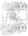
図1は、本発明に係るコンバインドサイクル発電プラントを多軸型に適用した第1実施形態を示す概略系統図である。なお、本実施形態に係るコンバインドサイクル発電プラントは、蒸気タービンプラント1台とガスタービンプラントおよび排熱回収ボイラの2台の組み合わせを例示として示している。
【0035】
全体を符号1で示すコンバインドサイクル発電プラントは、第1ガスタービンプラント2aに連接させた第1排熱回収ボイラ3aと、軸を知り離した別置の蒸気タービンプラント4と、さらに蒸気タービンプラント4の軸と切り離した別置きの第2ガスタービンプラント2bに連接させた第2排熱回収ボイラ3bとを備えた構成になっている。
【0036】
第1ガスタービンプラント2aは、発電機5a、空気圧縮機6a、ガスタービン燃焼器7a、ガスタービン8aを備え、空気圧縮機6aで吸い込んだ大気ARを高圧化してガスタービン燃焼器7aに案内し、その高圧空気に燃料を加えて燃焼ガスを生成し、その燃焼ガスをガスタービン8aに案内して膨張仕事をさせ、その際発生する回転トルクで発電機5aを回転駆動するとともに、その排ガス(排熱)を蒸気発生源として第1排熱回収ボイラ3aに供給するようになっている。なお、第2ガスタービンプラント2bは、各構成部品が第1ガスタービンプラント2aのそれと同一なので、部品番号に添字bを付し、その重複説明を省略する。
【0037】
第1排熱回収ボイラ3aは、軸方向に沿って延びるケーシング9aを備え、ケーシング9a内を流れる排ガスの流れ方向に沿って順に、第3高圧過熱器10a、再熱器11a、第2高圧過熱器12a、第1高圧過熱器13a、高圧ドラム14aに連通させた高圧蒸発器15a、中圧過熱器16a、第3高圧節炭器17a、低圧過熱器18a、中圧ドラム19aに連通させた中圧蒸発器20a、第2中圧節炭器21a、第2高圧節炭器22a、低圧ドラム23aに連通させた低圧蒸発器24a、第1高圧節炭器25a、第1中圧節炭器26aを備え、高、中、低の各蒸発器15a、20a、24aで蒸発した飽和蒸気を高、中、低の各蒸気ドラム14a、19a、23aにより気液分離を図っている。なお、第2排熱回収ボイラ3bは、各構成部品が第1排熱回収ボイラ3aのそれと同一なので、部品番号に添字bを付し、その重複説明を省略する。
【0038】
一方、蒸気タービンプラント4は、高圧タービン27、中圧タービン28、低圧タービン29、発電機30を共通軸で互に連結させており、第1排熱回収ボイラ3aの第3高圧過熱器10aおよび第2排熱回収ボイラ3bの第3高圧過熱器10bのそれぞれから発生する過熱蒸気を、第1主蒸気系31aおよび第2主蒸気系31bの合流点Aで合流させ、その合流蒸気を主蒸気止め弁32、蒸気加減弁33を介して高圧タービン27に供給するようになっている。
【0039】
高圧タービン27は、合流蒸気に膨張仕事をさせた後、タービン排気として分岐点Bで分流させ、各分流蒸気を第1低温再熱蒸気系34aの第1高圧排気分配弁35aおよび第2低温再熱蒸気系34bの第2高圧排気分配弁35bのそれぞれを介して分岐点Cに供給するようになっている。
【0040】
分岐点Cに供給されたタービン排気のうち、その一部は低温再熱流量調整弁36aで適量に流量コントロールされた後、第1排熱回収ボイラ3aの再熱器11aに供給され、ここで加熱された後、再熱蒸気として再熱蒸気系37aに供給される。また、タービン排気の残りは、低温再熱逆止弁36cを介して合流点Dで、第1排熱回収ボイラ3aの中圧ドラム19aから中圧過熱器16a、中圧過熱蒸気系38aを介して供給される全流量の中圧過熱蒸気に合流し、その合流蒸気を冷却蒸気として冷却蒸気供給系39aを介してガスタービン8aの高温部40aに供給される。
【0041】
ガスタービン8aは、その高温部40aを冷却させた後の冷却蒸気を、回収蒸気として冷却蒸気回収系41aを介して再熱蒸気系37aの合流点Eで再熱蒸気に合流させるようになっている。
【0042】
合流点Eで再熱器11aからの再熱蒸気と冷却蒸気回収系41からの回収蒸気を合流させた再熱蒸気系37aは、合流点Fで再び第2排熱回収ボイラ3bの再熱器11bからの再熱蒸気と合流させ、その合流蒸気を再熱蒸気組み合わせ弁42、インタセプト弁43を介して中圧タービン28に供給する。
【0043】
中圧タービン28は、合流蒸気に膨張仕事をさせた後、タービン排気として低圧タービン29に供給する。また、中圧タービン28は、第1排熱回収ボイラ3aの低圧過熱器18aおよび第2排熱回収ボイラ3bの低圧過熱器18bのそれぞれから供給された低圧過熱蒸気を合流点Gで合流させ、その合流低圧過熱蒸気を低圧蒸気組み合せ弁44、低圧加減弁45を介して合流点Hで再び上述のタービン排気と合流させて低圧タービン29に供給する。なお、第2排熱回収ボイラ3bの個々の蒸気の流は、上述第1排熱回収ボイラ3aのそれと同一なので、その説明を省略する。
【0044】
低圧タービン29は、合流蒸気に膨張仕事をさせ、その際、発生する回転トルクにより発電機30を回転駆動するとともに、膨張仕事後の合流蒸気をタービン排気として復水器46に供給する。
【0045】
復水器46には、第1復水・給水系47aと第2復水・給水系47bとが設けられている。
【0046】
第1復水・給水系47aは、復水器46で低圧タービン29からのタービン排気を凝縮させた復水を、復水ポンプ48で昇圧させ、分岐点Iで分流させた後、その一部を給水として第1給水ポンプ49aに供給する。第1給水ポンプ49aは、給水の一部を途中段落で、いわゆる中段抽水し、その抽水を第1排熱回収ボイラ3aの第1中圧節炭器26aに供給するとともに、給水の残りを第1排熱回収ボイラ3aの第1高圧節炭器25aに供給する。なお、第2復水・給水系47bは、第1復水・給水系47aの構成と同一なので、部品番号に添字bを付し、その重複説明を省略する。
【0047】
第1排熱回収ボイラ3aは、第1復水・給水系47aからの第1中圧節炭器26aおよび第1高圧節炭器25aのそれぞれに供給された給水を、第1ガスタービンプラント2aからの排ガスと熱交換させ、低、中、高の各蒸気ドラム23a,19a、14aで気液分離をさせた後、その過熱蒸気を蒸気タービンプラント4の駆動蒸気として、またガスタービン18aの高温部40の冷却蒸気としてそれぞれ供給するようになっている。この場合、第1排熱回収ボイラ3aは、第1高圧過熱器13aの出口から第2高圧過熱器12aの入口に接続する過熱蒸気管50aの途中から分岐し、流量調整弁51aを備えたバイパス系52aを第2高圧過熱器12aの出口に接続させ、第2高圧過熱器12aから発生する過熱蒸気が設計値の温度・圧力を超えているとき、流量調整弁51で流量制御し、適温・適圧の過熱蒸気にして第3高圧過熱器10a、第1主蒸気系31aを介して高圧タービン27に供給するようになっている。なお、第2高圧過熱器12aの出口側にバイパス系52aを設けたのは、第2高圧過熱器12aから発生した過熱蒸気が高い場合、例えば第1復水・給水系47aの給水を投入し、適温・適圧に調整することも考えられるが、その適温・適圧に調整した過熱蒸気が高圧タービン27の駆動蒸気として使用された後、ガスタービン8aの高温部40aの冷却蒸気として使用することを勘案すると、上述の給水の清浄度の管理が不十分であり、ガスタービン8aの高温部40aにダストが堆積して目詰りを引き起すおそれがあることを考慮したものである。
【0048】
次に、起動運転時または部分負荷運転時、ガスタービン8aの高温部40aを蒸気で冷却し、回収させる際の本実施形態に係るコンバインドサイクル発電プラントの運転方法を説明する。
【0049】
多軸型のコンバインドサイクル発電プラント1は、1台の蒸気タービンプラント4に複数台のガスタービンプラント2a,2bを組み合わせた構造ゆえに、ガスタービンプラント2a,2bの運転台数が少なくなると、高圧タービン27の駆動蒸気や流量が減少するため圧力が変動し、必然的にタービン排気としての冷却蒸気の圧力も変動する。
【0050】
例えば、起動運転時あるいは部分負荷運転時、第1ガスタービンプラント2aおよび第2ガスタービンプラント2bのうち、1台を運転させる場合(以下1台運転と呼ぶ)、高圧タービン27は、ガスタービン8aの高温部40aを供給する冷却蒸気の流量が2台運転のときに較べ半分になり、その圧力も2台運転時の設計圧力、例えば3.63MPaが1.8MPaの圧力に半減する。このため、高圧タービン27は、そのタービン排気を冷却蒸気としてガスタービン8aの高温部40aに供給する場合、ガスタービン8aの高温部40aの圧力損失を考慮すると冷却蒸気の流れが悪くなり、冷却が難しくなる。また、高圧タービン27は、冷却蒸気の流量が半減すると、タービン排気の温度が高くなり、ガスタービン8aの高温部40aを冷却するに必要な冷却蒸気の温度が許容値を超え、ガスタービン8aの高温部40aを冷却させることができなくなる。
【0051】
このように、第1ガスタービンプラント2aおよび第2ガスタービンプラント2bのうち、いずれかが1台運転に入ると、例えば、ガスタービン8aの高温部40aの冷却が難しくなるので、ガスタービン8aの高温部40aに適温・適圧の冷却蒸気を供給するには、高圧タービン27のタービン排気圧力を「高」にする運転と、そのタービン排気温度を「低」にする運転とが必要とされる。もっとも、タービン排気圧力「高」とタービン排気温度「低」とは、熱力学的に見て相反する関係になっているから、これら技術事項は互に独立して取り扱わなければならず、以下の運転方法が必要とされる。
【0052】
(1)高圧タービンのタービン排気圧力を「高」に運転する方法
1台運転の場合、本実施形態は、高圧タービン27から第1低温再熱蒸気系34aを介してガスタービン8aの高温部40aに供給されるタービン排気に、合流点Dで第1排熱回収ボイラ3aの中圧ドラム19aから中圧過熱器16a、中圧過熱蒸気系38aを介して供給される過熱蒸気を合流させ、その合流蒸気を冷却蒸気供給系39aを介してガスタービン8aの高温部40aに供給し、冷却後、その回収蒸気を冷却蒸気回収系41aを介して合流点Eで再熱蒸気系37aからの再熱蒸気に合流させ、その合流蒸気を再熱蒸気組み合せ弁42、インタセプト弁43を介して中圧タービン28に回収させているので、中圧過熱蒸気系38a、高温部40a、冷却蒸気回収系41aを流れる中圧過熱蒸気の圧力は、再熱蒸気系37aの再熱蒸気組み合せ弁42の入口側における合流蒸気の圧力によって決まる。つまり、再熱蒸気組み合せ弁42の弁開度を調整すると、中圧蒸気過熱系38a、冷却蒸気供給系39a、高温部40a、冷却蒸気回収系41aの蒸気圧力が変動する関係になっている。
【0053】
本実施形態は、この点に着目したもので、1台運転時、再熱蒸気組み合せ弁42の弁開度を絞ることにより中圧蒸気過熱系38a、冷却蒸気供給系39a、高温部40a、冷却蒸気回収系41aからの中圧過熱蒸気の圧力を「高」にし、適圧にしてガスタービン8aの高温部40aに供給したものである。なお、再熱蒸気組み合せ弁42は、冷却蒸気供給系39aおよび冷却蒸気回収系41aのいずれかに設けた圧力検出器(図示せず)の検出圧力信号に基づいて弁開度が設定されている。
【0054】
このように、本実施形態では、高圧タービン27から第1低温再熱蒸気系34a、冷却蒸気供給系39aを介してガスタービン8aの高温部40aに供給するタービン排気が圧力不足のとき、再熱蒸気組み合せ弁42の弁開度を絞って中圧蒸気過熱系38a、冷却蒸気供給系39a、高温部40a、冷却蒸気回収系41aの中圧過熱蒸気の圧力を「高」にし、適圧な冷却蒸気としてガスタービン8aの高温部40aを確実に冷却することができる。
【0055】
また、本実施形態では、ガスタービン8aの高温部40aの冷却後の蒸気を中圧タービン28に回収させるので、蒸気タービンプラント4の出力変動を低く抑えることができる。
【0056】
(2)高圧タービン27のタービン排気温度を「低」に運転する方法
通常、高圧タービン27は、1台運転を行うと、そのタービン排気の温度を高くする。また、高圧タービン27は、上述の再熱蒸気組み合せ弁42の弁開度を絞って再熱蒸気系37aの圧力を「高」にする、いわゆる前圧制御(Inlet
Pressure Control, 略してIPC)を行うと、そのタービン排気の温度をさら に高くなる。このため、高圧タービン27のタービン排気温度を「低」に運転するには、第1排熱回収ボイラ3aの第1高圧過熱器13aから第2高圧過熱器12a、第3高圧過熱器10a、第1主蒸気系31aを介して高圧タービン27に供給される主蒸気(過熱蒸気)の温度を「低」にし、かつ第1主蒸気系31aの主蒸気止め弁32または蒸気加減弁33の弁開度を絞ってタービン効率を増加させながらタービン排気温度を「低」にする定圧運転が必要となる。
【0057】
本実施形態に係る運転方法は、先ず、第1高圧過熱器13aの出口と第2高圧過熱器12aの入口とを接続する過熱蒸気管50aから分岐したバイパス系52aの流量調整弁51aを開弁させる。流量調整弁51aを開弁させると、第1高圧過熱器13aから第3高圧過熱器10a、主蒸気系31aを介して高圧タービン27に供給する主蒸気は、第2高圧過熱器12aをバイパスさせているので、その温度を下げることができる。
【0058】
しかし、主蒸気の温度が下ったと言っても、高圧タービン27からガスタービン8aの高温部40aに供給される冷却蒸気としてのタービン排気は、適温範囲の上限値にとどまっている。このため、高圧タービン27の運転幅を広げ、より一層安定運転を行わせるには、第1主蒸気系31aのIPCによる定圧運転が行われる。高圧タービン27は、第1主蒸気系31aの主蒸気止め弁32または蒸気加減弁33に弁開度を絞らせて定圧運転を行うと、主蒸気の温度が若干高くなるが、その高くなった分、より多く膨張仕事をしてタービン効率を向上させるので、その結果、タービン排気の温度をより低く下げ、安定運転を確保することができる。なお、主蒸気止め弁32または蒸気加減弁33は、冷却蒸気供給系39aおよび冷却蒸気回収系41aのいずれかに設けた温度検出器(図示せず)の検出温度信号に基づいて弁開度が設定されている。
【0059】
このように本実施形態では、第1高圧過熱器13aに設けたバイパス系52aを利用して主蒸気温度を下げ、かつ主蒸気止め弁32または蒸気加減弁33の弁開度を絞って高圧タービン27に定圧運転させ、タービン排気温度をガスタービン8aの高温部40aに必要な適温に確実に下げるので、ガスタービン8aの高温部40aを確実に冷却することができる。
【0060】
なお、本実施例では2台のプラントのみで説明したが、3台以上の複数のプラントにおいて、その台数を減少させた運転にも適用させることができるのは勿論である。
【0061】
図2は、本発明に係るコンバインドサイクル発電プラントを一軸型に適用した第2実施形態を示す概略系統図である。なお、第1実施形態の構成部品または対応する部分には、添字aを付した同一番号を使用する。
【0062】
一般に、一軸型は、1台のガスタービンプラントに対し、1台の蒸気タービンプラントおよび1台の排熱回収ボイラをペアにして組み合わせ、ガスタービンプラントから排熱回収ボイラに供給される排ガス量の変動と、排熱回収ボイラから蒸気タービンプラントに供給される蒸気流量の変動とが追従関係になっているから、多軸型に較べて複雑な蒸気流量制御を行う必要がない。
【0063】
しかし、ガスタービンプラントは、その性質上、夏場のように高気温になると、設計値通りの出力が出ないにもかかわらず排ガス温度が高くなり、これに伴って排熱回収ボイラから蒸気タービンプラントに供給される主蒸気の温度が高くなり、蒸気タービンプラントからガスタービン高温部に供給される冷却蒸気としてのタービン排気の温度・圧力も適温の運転範囲を超えることがある。特に、夏場、ガスタービンプラントに部分負荷運転を行わせると、この傾向は強い。
【0064】
このように夏場のように大気温が予め定められた所定温度になった場合の問題点に対処するために、本実施形態では、第1実施形態と同様に、第1排熱回収ボイラ3aの第1高圧過熱器13aの出口と第2高圧過熱器12aの入口とを接続する過熱蒸気管50aに、流量調整弁51aを備えたバイパス系52aを設け、第1高圧過熱器13aから発生した過熱蒸気を、バイパス系52a、第3高圧過熱器10a、主蒸気系31aを介して比較的温度の低い主蒸気として高圧タービン27に供給し、膨張後のタービン排気を第1低温再熱蒸気系34aを介して分流点Cで分流させ、その分流蒸気の一方を低温再熱流量調整弁36aで適正量にコントロールして再熱器11aに供給するとともに、残りの分流蒸気を低温再熱逆止弁36c、流量調整弁53aを備えた冷却蒸気供給系39を介してガスタービン8aの高温部40aに供給し、冷却後、回収冷却蒸気を流量調整弁54aを備えた冷却蒸気回収系41aを介して再熱蒸気系37aの合流点Eで再熱器11aからの再熱蒸気と合流させ、その合流蒸気を再熱蒸気組み合せ弁42、インタセプト弁43を介して中圧タービン28に回収させたものである。なお、高圧タービン27のタービン排気が何らかの事情でガスタービン8aの高温部40aに供給する冷却蒸気として適温・適圧の予め定められた運転範囲をはずれている場合、第1主蒸気系39aの主蒸気止め弁32または蒸気加減弁33の弁開度を絞り、高圧タービン27に定圧運転をさせても良く、また、再熱蒸気系37aの再熱蒸気組み合せ弁42の弁開度を絞り、第1排熱回収ボイラ3aの中圧ドラム19aから発生する中圧過熱蒸気の圧力を高め、その中圧過熱蒸気を中圧過熱蒸気系38aを介して合流点Dで高圧タービン27からのタービン排気に合流させても良い。
【0065】
このように、本実施形態では、夏場のように気温が高く、第1排熱回収ボイラ3aから高圧タービン29に供給される主蒸気温度が高いとき、第1排熱回収ボイラ3aのバイパス系52aを利用し、第1高圧過熱器13aから発生する過熱蒸気を比較的低い主蒸気温度にして高圧タービン27に供給するので、高圧タービン27で膨張後のタービン排気の温度もガスタービン8aの高温部40aを冷却するに必要な適温の運転範囲にすることができる。
【0066】
したがって、本実施形態では、高圧タービン27のタービン排気を適温の運転範囲にしているので、ガスタービン8aの高温部40aを確実に冷却することができ、ガスタービン8aの高温化に対処することができる。
【0067】
また、本実施形態では、ガスタービン8aの高温部40aの冷却後の蒸気を中圧タービン28に回収させるので、蒸気タービンプラント4の出力増となるためプラント熱効率向上を実現することができる。
【0068】
【発明の効果】
以上の説明の通り、本発明に係るコンバインドサイクル発電プラントの運転方法およびコンバインドサイクル発電プラントは、高圧タービンのタービン排気をガスタービンの高温部に冷却蒸気として供給する際、そのタービン排気が適温・適圧の運転範囲からはずれているとき、中圧タービンの再熱蒸気系に前圧制御を行わせ、中圧ドラムから発生する中圧過熱蒸気の圧力を高め、その中圧過熱蒸気をタービン排気に合流させて適圧に調整するとともに、排熱回収ボイラの第1高圧過熱器から発生する過熱蒸気をバイパス系を利用して低い温度の主蒸気として高圧タービンに供給し、その際、高圧タービンに定圧運転を行わせ、そのタービン排気を適温に調整しているので、ガスタービンの高温部を確実に冷却することができ、ガスタービンの高温化に充分に対処することができる。
【0069】
また、本発明に係るコンバインドサイクル発電プラントの運転方法およびコンバインドサイクル発電プラントは、ガスタービンの高温部を冷却後の蒸気を、排熱回収ボイラの再熱器から供給される再熱蒸気に合流させて中圧タービンに回収させるので、蒸気タービンプラントの出力増となり、プラント熱効率を向上させることができる。
【図面の簡単な説明】
【図1】本発明に係るコンバインドサイクル発電プラントを多軸型に適用した第1実施形態を示す概略系統図。
【図2】本発明に係るコンバインドサイクル発電プラントを一軸型に適用した第2実施形態を示す概略系統図。
【符号の説明】
1 コンバインドサイクル発電プラント
2a 第1ガスタービンプラント
2b 第2ガスタービンプラント
3a 第1排熱回収ボイラ
3b 第2排熱回収ボイラ
4 蒸気タービンプラント
5a,5b 発電機
6a,6b 空気圧縮機
7a,7b ガスタービン燃焼器
8a,8b ガスタービン
9a,9b ケーシング
10a,10b 第3高圧過熱器
11a,11b 再熱器
12a,12b 第2高圧過熱器
13a,13b 第1高圧過熱器
14a,14b 高圧ドラム
15a,15b 高圧蒸発器
16a,16b 中圧過熱器
17a,17b 第3高圧節炭器
18a,18b 低圧過熱器
19a,19b 中圧ドラム
20a,20b 中圧蒸発器
21a,21b 第2中圧節炭器
22a,22b 第2高圧節炭器
23a,23b 低圧ドラム
24a,24b 低圧蒸発器
25a,25b 第1高圧節炭器
26a,26b 第1中圧節炭器
27 高圧タービン
28 中圧タービン
29 低圧タービン
30 発電機
31a 第1主蒸気系
31b 第2主蒸気系
32 主蒸気止め弁
33 蒸気加減弁
34a 第1低温再熱蒸気系
34b 第2低温再熱蒸気系
35a 第1高圧排気分配弁
35b 第2高圧排気分配弁
36a,36b 低温再熱流量調整弁
36c,36d 低温再熱逆止弁
37a,37b 再熱蒸気系
38a,38b 中圧過熱蒸気系
39a,39b 冷却蒸気供給系
40a,40b 高温部
41a,41b 冷却蒸気回収系
42 再熱蒸気組み合せ弁
43 インタセプト弁
44 低圧蒸気組み合せ弁
45 低圧加減弁
46 復水器
47a 第1復水・給水系
47b 第2復水・給水系
48 復水ポンプ
49a 第1給水ポンプ
49b 第2給水ポンプ
50a,50b 過熱蒸気管
51a,51b 流量調整弁
52a,52b バイパス系
53a 流量調整弁
54a 流量調整弁[0001]
BACKGROUND OF THE INVENTION
The present invention relates to an operation method of a combined cycle power plant and a combined cycle power plant that cools a high temperature portion of a gas turbine plant using steam as a cooling medium.
[0002]
[Prior art]
In recent thermal power plants, in order to improve plant thermal efficiency, many combined cycle power plants that combine a gas turbine plant, a steam turbine plant, and an exhaust heat recovery boiler are operated as actual machines. This combined cycle power plant includes a so-called single-shaft type mainly based on plant operation and a so-called multi-axis type mainly based on efficiency during rated operation.
[0003]
In the single shaft type, one steam turbine is directly connected to one gas turbine, and the number of shafts is a plurality of shaft series so as to match the planned output. In addition, the multi-shaft type is one in which the shafts of a plurality of gas turbines are separately separated from one steam turbine.
[0004]
In the former, one axis series and the other axis series do not interfere with each other. Therefore, when the output of multiple axis series is lowered during partial load operation, the plant thermal efficiency is not drastically reduced. It is advantageous. In the latter, the steam turbine is the main component and the capacity (output) is increased. Therefore, the plant thermal efficiency during rated operation is higher than that of the single-shaft type because of the increased capacity. Yes.
[0005]
Thus, it is called a uniaxial type and is called a multi-axial type, both of which have advantages, so that all types are operated as actual machines.
[0006]
By the way, in any type of combined-cycle power plant of the single-shaft type or the multi-shaft type, further improvements in plant thermal efficiency are being studied in order to save fuel and reduce the unit price of power generation. This plant thermal efficiency is calculated from the ratio of the total heat output of each plant to the total heat input of each plant of the gas turbine plant, steam turbine plant, and exhaust heat recovery boiler. When the steam turbine plant, exhaust heat recovery boiler and gas turbine plant are reviewed from the viewpoint of improving the plant thermal efficiency, the steam turbine plant and exhaust heat recovery boiler have already reached their limits, and the improvement of the thermal efficiency of the gas turbine plant is combined. It is expected to lead to improved plant thermal efficiency of cycle power plants.
[0007]
The gas turbine plant can improve the thermal efficiency as the gas combustion temperature at the gas turbine is higher. The progress of cooling technology coupled with the recent development of heat-resistant materials has made it possible to reduce the gas combustion temperature at the gas turbine. The temperature is changing from 1000 ° C to 1500 ° C through 1300 ° C.
[0008]
When the temperature of the combustion gas at the inlet of the gas turbine is set to 1500 ° C. or higher, although a heat-resistant material has been developed, a gas turbine high temperature part, for example, a gas turbine stationary blade that is directly exposed to the combustion gas, a gas turbine blade, The allowable metal temperature of the combustor liner, transition piece, etc. has already reached its limit, and there is a risk of accidents such as material breakage or melting during operation with many start / stop operations or continuous operation over a long period of time. coming out. For this reason, even if the inlet combustion gas temperature of the gas turbine is increased, as a technology that can be maintained within the allowable metal temperature of each component of the gas turbine high-temperature part, the development of cooling the gas turbine high-temperature part using air is advanced, It has already been realized as a practical machine.
[0009]
However, when cooling the high-temperature part of the gas turbine using air, the supply source is obtained from an air compressor directly connected to the gas turbine, and tens of percent of high-pressure air supplied from the air compressor to the gas turbine is It is used for cooling the high-temperature part of the gas turbine, and the high-pressure air after cooling the turbine blades is blown out to the gas turbine drive gas, so the temperature of the gas turbine drive gas is reduced and mixing loss is generated, thereby improving the plant thermal efficiency. It was making it difficult.
[0010]
Recently, the utilization of steam as a cooling medium has been reviewed in high-temperature parts of gas turbines, such as gas turbine stationary blades and gas turbine rotor blades, and has already been reviewed by the American Society of Mechanical Engineers (ASME paper, 92-GT-240) and -163961 and so on.
[0011]
Steam has twice the specific heat compared to air, has excellent heat transfer performance, and can be cooled in a closed loop, contributing to improved plant efficiency without temperature drop and mixing loss of gas turbine drive gas. Therefore, application to practical machines is expected.
[0012]
[Problems to be solved by the invention]
Even when steam cooling is considered promising in this way, there are some problems when applied to the high temperature part of a gas turbine because it is a multi-shaft combined cycle power plant.
[0013]
Generally, when steam-cooling a high temperature part of a gas turbine, driving steam of a steam turbine plant is used.
[0014]
However, since a multi-shaft combined cycle power plant is a combination of a plurality of gas turbine plants with respect to a single steam turbine plant, for example, one of the plurality of gas turbine plants during partial load operation. The steam conditions (temperature, pressure, flow rate) supplied from the exhaust heat recovery boiler to the steam turbine plant fluctuate significantly from the design values. When the high temperature part of the gas turbine is cooled under the fluctuating steam conditions, Inconveniences and problems occur.
[0015]
For example, if the temperature of the steam that cools the high-temperature part of the gas turbine is high, it will not be possible to maintain the material strength of the gas turbine rotor and stator blades, the gas turbine rotor, etc., which will cause damage and melting. Conversely, when the temperature of the steam is low, excessive thermal stress based on the temperature difference between the gas turbine driving gas and the cooling steam is locally generated in the gas turbine rotor blade and the gas turbine rotor. Furthermore, when the temperature of the steam is low, it tends to become drainage, which causes generation of local thermal stress accompanying supercooling.
[0016]
On the other hand, if the steam pressure is high, the gas turbine blades and stator blades are made thin, so there is a risk of damage due to so-called ballooning (expansion due to internal pressure), and if the steam pressure is low, the gas turbine driving gas There is a risk of inflow into the wing.
[0017]
In addition, when the flow rate of steam is reduced, the gas turbine rotor and stator blades, the gas turbine rotor, etc. cannot be cooled satisfactorily and the strength of the material cannot be maintained, making it difficult to cope with the high temperature of the gas turbine plant. .
[0018]
Furthermore, when the temperature and pressure of the steam is high, it is considered that water is introduced using a temperature reducer / decompressor to adjust the temperature to the appropriate temperature / pressure, but the cleanliness of the water is insufficiently controlled. If there is, dust accumulates in the passage in the gas turbine rotor blade, causing clogging,Cooling performanceMay cause oxidation and corrosion.
[0019]
As described above, in the multi-shaft combined cycle power plant, when the gas turbine high-temperature part is steam-cooled, the variation in the steam conditions of the cooling steam supplied from the steam turbine plant to the gas turbine high-temperature part and the number of operating gas turbine plants Since the increase and decrease are inseparable, it is necessary to keep the steam conditions from changing. In particular, during start-up operation and partial load operation, it is difficult to adjust the steam condition of the cooling steam supplied to the high-temperature part of the gas turbine within the range of the design value, because it is an undeveloped field. It is.
[0020]
The present invention has been made on the basis of such a technical background, so that even when there is a decrease in the number of operating gas turbine plants, it is possible to supply cooling steam of appropriate temperature and pressure to the high temperature portion of the gas turbine. In addition, an object of the present invention is to provide a combined cycle power plant operating method and a combined cycle power plant in which the steam turbine plant can recover the cooled steam satisfactorily so as to keep the output fluctuation of the steam turbine plant low. .
[0021]
[Means for Solving the Problems]
In order to achieve the above-described object, the combined cycle power plant operating method according to the present invention combines a gas turbine plant with a steam turbine plant and an exhaust heat recovery boiler as described in claim 1 to provide a steam turbine plant. In the operation method of the combined cycle power plant, the turbine exhaust gas is supplied to the gas turbine high temperature section of the gas turbine plant, and the gas turbine high temperature section is cooled and then recovered by the steam turbine plant.andDuring partial load operationIn one of the operating states,Waste heat recovery boilerBypass at least a part of the steam that flows through a part of the high-pressure superheaterWhile supplying to the high pressure turbine of the steam turbine plant,Reduce the opening of the main steam system valveA reheat steam system for connecting the reheater of the exhaust heat recovery boiler to the intermediate pressure turbine of the steam turbine plant while allowing the high pressure turbine to perform a constant pressure operationThe pre-pressure control is performed on the reheat steam system by reducing the valve opening ofThe steam generated from the intermediate pressure drum of the exhaust heat recovery boiler is joined to the turbine exhaust after being expanded by the high-pressure turbine, and the combined steam is supplied to the gas turbine high-temperature section to be cooled, and after cooling, the combined steam is steamed. In this method, the steam is combined with the reheated steam from the reheater and is recovered by the steam intermediate pressure turbine.
[0022]
In order to achieve the above object, the combined cycle power plant operating method according to the present invention reduces the number of operating gas turbine plants installed in a plurality of units during partial load operation as described in claim 2. It is the method characterized by being at the time of letting it drive.
[0023]
In order to achieve the above-mentioned object, the operation method of the combined cycle power plant according to the present invention, as described in claim 3, during start-up operation, when the atmospheric temperature is equal to or higher than a predetermined temperature, Alternatively, the method is characterized in that the steam temperature and pressure from the high-pressure turbine supplied to the gas turbine are out of a predetermined range.
[0024]
In order to achieve the above-described object, the combined cycle power plant operating method according to the present invention is as described in claim 4, wherein the high-pressure turbine is operated at a constant pressure by connecting the exhaust heat recovery boiler and the high-pressure turbine to each other. This is a method in which the valve opening is reduced by either one of the main steam stop valve and the steam control valve installed in the main steam system.
[0025]
In order to achieve the above-mentioned object, the operating method of the combined cycle power plant according to the present invention is a valve that restricts the valve opening degree of any one of the main steam stop valve and the steam control valve as described in claim 5. The signal is a method characterized in that it is a temperature of one of a cooling steam supply system and a cooling steam recovery system provided in the high temperature section of the gas turbine.
[0026]
In order to achieve the above-described object, the combined cycle power plant operating method according to the present invention is characterized in that the preheat control of the reheat steam system is performed by the reheat provided in the reheat steam system. In this method, the opening of the steam combination valve is reduced.
[0027]
In order to achieve the above-described object, the combined cycle power plant operating method according to the present invention provides a valve signal for restricting the reheat steam combination valve, which is a cooling provided in the high temperature section of the gas turbine. The method is characterized in that the pressure is one of a steam supply system and a cooling steam recovery system.
[0028]
In order to achieve the above-mentioned object, the combined cycle power plant according to the present invention is as described in claim 8,An exhaust heat recovery boiler that generates steam using exhaust gas from the gas turbine plant, a steam turbine plant that uses steam generated by the exhaust heat recovery boiler as a power source, and a gas turbine high-temperature section of the gas turbine plant As part of a system for supplying gas turbine cooling steam that cools the high temperature part of the gas turbine while cooling part or all of the gas turbine, the low-temperature recirculation is performed from the high-pressure turbine of the steam turbine plant to the exhaust heat recovery boiler reheater. A medium pressure steam from the medium pressure superheater of the exhaust heat recovery boiler, together with a cooling steam supply system that branches from the low temperature reheat steam system that directs the hot steam and leads part or all of the low temperature reheat steam to the high temperature section of the gas turbine. The medium pressure steam superheating system that guides the cooling steam to the cooling steam supply system and the high pressure superheater in the exhaust heat recovery boiler are divided into at least two parts. The steam that has exited from the first high pressure superheater has a configuration that is continuously led from the first high pressure superheater to the second high pressure superheater and branches from a steam pipe that leads the steam from the first high pressure superheater to the second high pressure superheater, A gas turbine having a bypass system for bypassing the second high-pressure superheater with at least a part of the first high-pressure superheater outlet steam and a flow rate adjusting valve provided in the bypass system, during start-up operation or partial load operation When the cooling steam exceeds the allowable temperature value, the flow control valve of the bypass system is opened to bypass a part or all of the first high pressure superheater outlet steam to the second high pressure superheater and the cooling steam. The low-temperature reheat steam supplied to the supply system is within the temperature tolerance.Is.
[0029]
In order to achieve the above object, the combined cycle power plant according to the present invention controls the flow rate of the turbine exhaust supplied from the high-pressure turbine to the reheater as described in claim 9. A low-temperature reheat flow rate adjusting valve is provided.
[0030]
In order to achieve the above object, a combined cycle power plant according to the present invention, as described in claim 10,A temperature detector is provided in at least one of the inlet pipe to the gas turbine high temperature section and the outlet pipe from the gas turbine high temperature section, and the detected value of the temperature detector is the allowable temperature of the gas turbine cooling steam with respect to the load of the gas turbine. The flow rate regulating valve of the bypass system is opened to bypass part or all of the first high pressure superheater outlet steam to the second high pressure superheater.Is.
[0031]
In order to achieve the above-mentioned object, the combined cycle power plant according to the present invention comprises a plurality of gas turbine plants connected to an exhaust heat recovery boiler, and a steam turbine. The plant is one multi-shaft type that can be separated from the shaft of the gas turbine plant and is installed separately.
[0032]
In order to achieve the above-mentioned object, the combined cycle power plant according to the present invention, as described in claim 12,The gas turbine plant is a single-shaft type that directly connects a steam turbine plant.It is characterized by being.
[0033]
DETAILED DESCRIPTION OF THE INVENTION
DESCRIPTION OF EMBODIMENTS Hereinafter, an operation method of a combined cycle power plant and an embodiment of a combined cycle power plant according to the present invention will be described with reference to the accompanying drawings and the part numbers given in the drawings. Prior to the description of the operation method of the combined cycle power plant according to the present invention, the configuration will be described.
[0034]
FIG. 1 is a schematic system diagram showing a first embodiment in which a combined cycle power plant according to the present invention is applied to a multi-shaft type. In the combined cycle power plant according to the present embodiment, a combination of two steam turbine plants, a gas turbine plant, and an exhaust heat recovery boiler is shown as an example.
[0035]
The combined cycle power plant generally indicated by reference numeral 1 includes a first exhaust
[0036]
The first
[0037]
The first exhaust
[0038]
On the other hand, the steam turbine plant 4 includes a high-
[0039]
The high-
[0040]
A part of the turbine exhaust supplied to the branch point C is controlled to a suitable amount by the low-temperature reheat flow
[0041]
The
[0042]
The
[0043]
The
[0044]
The low-pressure turbine 29 causes the combined steam to perform expansion work, and the
[0045]
The
[0046]
The first condensate /
[0047]
The first exhaust
[0048]
Next, an operation method of the combined cycle power plant according to the present embodiment when the
[0049]
Since the multi-shaft combined cycle power plant 1 has a structure in which a plurality of
[0050]
For example, when one of the first
[0051]
Thus, when one of the first
[0052]
(1) Method of operating high pressure turbine exhaust pressure to “high”
In the case of single-unit operation, in the present embodiment, the first exhaust heat recovery is performed at the junction D to the turbine exhaust supplied from the high-
[0053]
The present embodiment pays attention to this point, and during operation of one unit, by reducing the valve opening of the reheat
[0054]
As described above, in this embodiment, when the turbine exhaust supplied from the high-
[0055]
Moreover, in this embodiment, since the steam after cooling of the
[0056]
(2) Method of operating the turbine exhaust temperature of the high-
Normally, when one high-
When pressure control (IPC for short) is performed, the temperature of the turbine exhaust becomes higher. For this reason, in order to operate the turbine exhaust temperature of the
[0057]
In the operation method according to the present embodiment, first, the superheated steam pipe connecting the outlet of the first high pressure superheater 13a and the inlet of the second high pressure superheater 12a.50aThe flow
[0058]
However, even if the temperature of the main steam is lowered, the turbine exhaust as cooling steam supplied from the high-
[0059]
As described above, in the present embodiment, the main steam temperature is lowered by using the
[0060]
In this embodiment, only two plants have been described, but it is needless to say that the present invention can be applied to an operation in which the number of plants is reduced in three or more plants.
[0061]
FIG. 2 is a schematic system diagram showing a second embodiment in which the combined cycle power plant according to the present invention is applied to a uniaxial type. In addition, the same number which attached | subjected the subscript a is used for the component of 1st Embodiment or a corresponding part.
[0062]
In general, the single-shaft type combines one steam turbine plant and one exhaust heat recovery boiler as a pair with one gas turbine plant, and the amount of exhaust gas supplied from the gas turbine plant to the exhaust heat recovery boiler is reduced. Since the fluctuation and the fluctuation of the flow rate of the steam supplied from the exhaust heat recovery boiler to the steam turbine plant are in a follow-up relationship, it is not necessary to perform complicated steam flow control as compared with the multi-shaft type.
[0063]
However, due to the nature of the gas turbine plant, when the temperature is high like in summer, the exhaust gas temperature becomes high despite the fact that the output does not come out as designed, and accordingly the steam turbine plant from the exhaust heat recovery boiler. As a result, the temperature and pressure of the turbine exhaust as the cooling steam supplied from the steam turbine plant to the gas turbine high temperature section may exceed the operating range of the appropriate temperature. In particular, this tendency is strong when the gas turbine plant is subjected to partial load operation in summer.
[0064]
Thus, in order to cope with the problem when the atmospheric temperature reaches a predetermined temperature as in summer, in the present embodiment, as in the first embodiment, the first exhaust
[0065]
Thus, in this embodiment, when the temperature is high as in summer and the main steam temperature supplied from the first exhaust
[0066]
Therefore, in the present embodiment, since the turbine exhaust of the high-
[0067]
Moreover, in this embodiment, since the steam after cooling of the
[0068]
【The invention's effect】
As described above, when the combined cycle power plant operating method and the combined cycle power plant according to the present invention supply the turbine exhaust of the high-pressure turbine to the high temperature part of the gas turbine as the cooling steam, the turbine exhaust is at a suitable temperature and suitable temperature. When the pressure is outside the operating range, the reheat steam system of the intermediate pressure turbine performs pre-pressure control to increase the pressure of the intermediate pressure superheated steam generated from the intermediate pressure drum, and the intermediate pressure superheated steam is used as turbine exhaust. Combined and adjusted to an appropriate pressure, the superheated steam generated from the first high-pressure superheater of the exhaust heat recovery boiler is supplied to the high-pressure turbine as main steam at a low temperature using a bypass system. Since the constant pressure operation is performed and the turbine exhaust is adjusted to an appropriate temperature, the high temperature part of the gas turbine can be reliably cooled. It is possible to sufficiently cope with the high temperature.
[0069]
Further, the combined cycle power plant operating method and the combined cycle power plant according to the present invention combine the steam after cooling the high temperature part of the gas turbine with the reheat steam supplied from the reheater of the exhaust heat recovery boiler. Therefore, the intermediate pressure turbine recovers the steam turbine plant, increasing the output of the steam turbine plant and improving the plant thermal efficiency.
[Brief description of the drawings]
FIG. 1 is a schematic system diagram showing a first embodiment in which a combined cycle power plant according to the present invention is applied to a multi-shaft type.
FIG. 2 is a schematic system diagram showing a second embodiment in which the combined cycle power plant according to the present invention is applied to a uniaxial type.
[Explanation of symbols]
1 Combined cycle power plant
2a First gas turbine plant
2b Second gas turbine plant
3a First exhaust heat recovery boiler
3b Second exhaust heat recovery boiler
4 Steam turbine plant
5a, 5b Generator
6a, 6b Air compressor
7a, 7b Gas turbine combustor
8a, 8b gas turbine
9a, 9b casing
10a, 10b Third high pressure superheater
11a, 11b Reheater
12a, 12b Second high pressure superheater
13a, 13b first high pressure superheater
14a, 14b High pressure drum
15a, 15b High pressure evaporator
16a, 16b Medium pressure superheater
17a, 17b Third high pressure economizer
18a, 18b Low pressure superheater
19a, 19b Medium pressure drum
20a, 20b Medium pressure evaporator
21a, 21b Second medium pressure economizer
22a, 22b Second high pressure economizer
23a, 23b Low pressure drum
24a, 24b Low pressure evaporator
25a, 25b First high pressure economizer
26a, 26b First medium pressure economizer
27 High-pressure turbine
28 Medium pressure turbine
29 Low pressure turbine
30 Generator
31a First main steam system
31b Second main steam system
32 Main steam stop valve
33 Steam control valve
34a First low-temperature reheat steam system
34b Second low temperature reheat steam system
35a First high-pressure exhaust distribution valve
35b Second high pressure exhaust distribution valve
36a, 36b Low-temperature reheat flow control valve
36c, 36d Low temperature reheat check valve
37a, 37b Reheat steam system
38a, 38b Medium pressure superheated steam system
39a, 39b Cooling steam supply system
40a, 40b High temperature part
41a, 41b Cooling steam recovery system
42 Reheat steam combination valve
43 Intercept Valve
44 Low pressure steam combination valve
45 Low pressure regulator
46 condenser
47a First condensate / water supply system
47b Second condensate / water supply system
48 Condensate pump
49a 1st water supply pump
49b 2nd water supply pump
50a, 50b Superheated steam pipe
51a, 51b Flow rate adjustment valve
52a, 52b Bypass system
53a Flow control valve
54a Flow control valve
Claims (12)
この排熱回収ボイラにより発生した蒸気を動力源とする蒸気タービンプラントと、
上記ガスタービンプラントのガスタービン高温部の一部または全部が蒸気により冷却されるとともに、
このガスタービン高温部を冷却するガスタービン冷却蒸気を供給する系統の一つとして、上記蒸気タービンプラントの高圧タービンから排熱回収ボイラ再熱器へ低温再熱蒸気を導く低温再熱蒸気系から分岐して上記低温再熱蒸気の一部もしくは全部を上記ガスタービン高温部へ導く冷却蒸気供給系と共に、
排熱回収ボイラの中圧過熱器から中圧蒸気を冷却蒸気供給系に導く中圧蒸気過熱系と、
上記排熱回収ボイラにおいて高圧過熱器が少なくとも二つ以上に分割されて高圧ドラムを出た蒸気は第1高圧過熱器から第2高圧過熱器に連続して導かれる構成を有するとともに、
第1高圧過熱器から第2高圧過熱器へ蒸気を導く蒸気配管から分岐して、第1高圧過熱器出口蒸気の少なくとも一部を前記第2高圧過熱器をバイパスさせるバイパス系統と当該 バイパス系統に設けられた流量調整弁とを有し、
起動運転時および部分負荷運転時のうち、いずれか一方の運転状態で、ガスタービン冷却蒸気がその温度許容値を超える場合に、前記バイパス系統の流量調整弁を開弁させて第1高圧過熱器出口蒸気の一部もしくは全部を前記第2高圧過熱器をバイパスさせて前記冷却蒸気供給系に供給される前記低温再熱蒸気を前記温度許容値内とすることを特徴とするコンバインドサイクル発電プラント。An exhaust heat recovery boiler that generates steam using exhaust gas from a gas turbine plant;
A steam turbine plant that uses steam generated by the exhaust heat recovery boiler as a power source;
A part or all of the gas turbine hot section of the gas turbine plant is cooled by steam,
As one of the systems for supplying gas turbine cooling steam that cools the high temperature section of this gas turbine, it branches from the low temperature reheat steam system that leads the low temperature reheat steam from the high pressure turbine of the steam turbine plant to the exhaust heat recovery boiler reheater Together with a cooling steam supply system for leading a part or all of the low temperature reheat steam to the high temperature section of the gas turbine,
An intermediate pressure steam superheating system for guiding the intermediate pressure steam from the intermediate pressure superheater of the exhaust heat recovery boiler to the cooling steam supply system;
In the exhaust heat recovery boiler, the high pressure superheater is divided into at least two and the steam that has exited the high pressure drum has a configuration that is continuously led from the first high pressure superheater to the second high pressure superheater ,
Branched from the vapor pipe from the first high-pressure superheater directs steam to the second high-pressure superheater, to at least a portion of the first high-pressure superheater outlet steam bypass line and the bypass line for bypassing the second high pressure superheater A flow regulating valve provided,
The first high pressure superheater is opened by opening the flow rate regulating valve of the bypass system when the gas turbine cooling steam exceeds the allowable temperature value in any one of the startup operation and the partial load operation . A combined cycle power plant characterized in that a part or all of the outlet steam bypasses the second high-pressure superheater and the low-temperature reheat steam supplied to the cooling steam supply system is within the temperature tolerance .
当該温度検出器の検出値がガスタービンの負荷に対してガスタービン冷却蒸気の温度許容値を超える場合に、前記バイパス系統の流量調整弁を開弁させて第1高圧過熱器出口蒸気の一部もしくは全部を第2高圧過熱器をバイパスさせることを特徴とする請求項8に記載のコンバインドサイクル発電プラント。 A temperature detector is provided in at least one of the inlet pipe to the gas turbine high temperature section and the outlet pipe from the gas turbine high temperature section ,
When the detected value of the temperature detector exceeds the temperature allowable value of the gas turbine cooling steam with respect to the load of the gas turbine, a part of the first high pressure superheater outlet steam is opened by opening the flow rate adjusting valve of the bypass system. Or the 2nd high voltage | pressure superheater is bypassed entirely, The combined cycle power plant of Claim 8 characterized by the above-mentioned .
Priority Applications (7)
| Application Number | Priority Date | Filing Date | Title |
|---|---|---|---|
| JP22999897A JP3913328B2 (en) | 1997-08-26 | 1997-08-26 | Operation method of combined cycle power plant and combined cycle power plant |
| TW087113915A TW384351B (en) | 1997-08-26 | 1998-08-24 | Combined cycle power generation plant and operating method thereof |
| US09/139,893 US6178734B1 (en) | 1997-08-26 | 1998-08-25 | Combined cycle power generation plant and operating method thereof |
| KR1019980034571A KR100313823B1 (en) | 1997-08-26 | 1998-08-26 | Combined cycle power plant and its operation method |
| CN98118532A CN1123682C (en) | 1997-08-26 | 1998-08-26 | Combined circulation generating apparatus and operation method thereof |
| US09/703,872 US6338241B1 (en) | 1997-08-26 | 2000-11-02 | Combined cycle power generation plant and operating method thereof |
| CNB031041531A CN1204335C (en) | 1997-08-26 | 2003-02-14 | Operation method for combined circular electricity generator |
Applications Claiming Priority (1)
| Application Number | Priority Date | Filing Date | Title |
|---|---|---|---|
| JP22999897A JP3913328B2 (en) | 1997-08-26 | 1997-08-26 | Operation method of combined cycle power plant and combined cycle power plant |
Publications (2)
| Publication Number | Publication Date |
|---|---|
| JPH1162515A JPH1162515A (en) | 1999-03-05 |
| JP3913328B2 true JP3913328B2 (en) | 2007-05-09 |
Family
ID=16901008
Family Applications (1)
| Application Number | Title | Priority Date | Filing Date |
|---|---|---|---|
| JP22999897A Expired - Fee Related JP3913328B2 (en) | 1997-08-26 | 1997-08-26 | Operation method of combined cycle power plant and combined cycle power plant |
Country Status (5)
| Country | Link |
|---|---|
| US (2) | US6178734B1 (en) |
| JP (1) | JP3913328B2 (en) |
| KR (1) | KR100313823B1 (en) |
| CN (2) | CN1123682C (en) |
| TW (1) | TW384351B (en) |
Families Citing this family (56)
| Publication number | Priority date | Publication date | Assignee | Title |
|---|---|---|---|---|
| WO1998046872A1 (en) * | 1997-04-15 | 1998-10-22 | Mitsubishi Heavy Industries, Ltd. | Combined cycle power generating plant and method of supplying cooling steam for gas turbine in same |
| US6608395B1 (en) * | 2000-03-28 | 2003-08-19 | Kinder Morgan, Inc. | Hybrid combined cycle power generation facility |
| JP4346213B2 (en) | 2000-06-06 | 2009-10-21 | 株式会社東芝 | Combined cycle power plant |
| EP1174591A1 (en) * | 2000-07-21 | 2002-01-23 | Siemens Aktiengesellschaft | Primary regulation process with combined gas- and steam turbines plants |
| GB2381046B (en) * | 2000-11-17 | 2003-10-15 | Toshiba Kk | Combined cycle power plant |
| CA2364125C (en) | 2000-11-28 | 2005-05-24 | Mitsubishi Heavy Industries, Ltd. | Steam cooling apparatus for gas turbine |
| US6499302B1 (en) * | 2001-06-29 | 2002-12-31 | General Electric Company | Method and apparatus for fuel gas heating in combined cycle power plants |
| US6851265B2 (en) * | 2002-02-19 | 2005-02-08 | Siemens Westinghouse Power Corporation | Steam cooling control for a combined cycle power plant |
| EP2103785A3 (en) * | 2002-08-09 | 2013-11-13 | Hitachi Ltd. | Combined cycle plant |
| AU2003288262A1 (en) * | 2002-12-09 | 2004-06-30 | Siemens Aktiengesellschaft | Method for operation of a gas and steam power station and gas and steam power station for carrying out said method |
| JP4386364B2 (en) * | 2005-07-07 | 2009-12-16 | 株式会社日立製作所 | Steam turbine piping, its manufacturing method, main steam piping and reheat piping for steam turbine and steam turbine power plant using the same |
| US7168233B1 (en) * | 2005-12-12 | 2007-01-30 | General Electric Company | System for controlling steam temperature |
| EP1801363A1 (en) * | 2005-12-20 | 2007-06-27 | Siemens Aktiengesellschaft | Power plant |
| US7928854B2 (en) * | 2006-03-20 | 2011-04-19 | Gary Martino | Techniques for smoke detection |
| KR100758676B1 (en) | 2006-09-27 | 2007-09-14 | 한국생산기술연구원 | A power generation device using saturated vapor and the method thereof |
| JP4918388B2 (en) * | 2007-03-29 | 2012-04-18 | 三菱重工業株式会社 | Combined power plant |
| US8424281B2 (en) * | 2007-08-29 | 2013-04-23 | General Electric Company | Method and apparatus for facilitating cooling of a steam turbine component |
| US7937928B2 (en) * | 2008-02-29 | 2011-05-10 | General Electric Company | Systems and methods for channeling steam into turbines |
| EP2131013A1 (en) * | 2008-04-14 | 2009-12-09 | Siemens Aktiengesellschaft | Steam turbine system for a power plant |
| US20100031933A1 (en) * | 2008-08-05 | 2010-02-11 | Prakash Narayan | System and assemblies for hot water extraction to pre-heat fuel in a combined cycle power plant |
| US8186142B2 (en) * | 2008-08-05 | 2012-05-29 | General Electric Company | Systems and method for controlling stack temperature |
| US8205451B2 (en) * | 2008-08-05 | 2012-06-26 | General Electric Company | System and assemblies for pre-heating fuel in a combined cycle power plant |
| AU2009294230B2 (en) * | 2008-09-17 | 2014-02-13 | Siemens Concentrated Solar Power Ltd. | Solar thermal power plant |
| US8146341B2 (en) * | 2008-09-22 | 2012-04-03 | General Electric Company | Integrated gas turbine exhaust diffuser and heat recovery steam generation system |
| CN101598328B (en) * | 2008-09-28 | 2013-12-25 | 广州粤能电力科技开发有限公司 | Steam temperature control method for boiler with big load variable rate and dedicated device thereof |
| US20100077722A1 (en) * | 2008-09-30 | 2010-04-01 | General Electric Company | Peak load management by combined cycle power augmentation using peaking cycle exhaust heat recovery |
| DE102008062588B4 (en) * | 2008-12-16 | 2010-11-25 | Siemens Aktiengesellschaft | Method for stabilizing the mains frequency of an electrical power network |
| US8276382B2 (en) * | 2009-03-17 | 2012-10-02 | General Electric Company | Systems and methods for pre-warming a heat recovery steam generator and associated steam lines |
| US20120067054A1 (en) | 2010-09-21 | 2012-03-22 | Palmer Labs, Llc | High efficiency power production methods, assemblies, and systems |
| US8887481B2 (en) * | 2010-12-10 | 2014-11-18 | Alstom Technology Ltd | Method for starting a combined cycle power plant |
| ITMI20102463A1 (en) * | 2010-12-30 | 2012-07-01 | Stamicarbon | METHOD FOR STARTING AND MANAGEMENT OF A COMBINED CYCLE THERMAL PLANT FOR ENERGY PRODUCTION AND ITS PLANT |
| US8726625B2 (en) * | 2011-04-12 | 2014-05-20 | General Electric Company | Combined cycle power plant |
| TWI482903B (en) * | 2011-12-06 | 2015-05-01 | Hon Hai Prec Ind Co Ltd | Module of combustion turbine engine |
| US20130199150A1 (en) * | 2012-02-03 | 2013-08-08 | General Electric Company | Steam injection assembly for a combined cycle system |
| JP6110706B2 (en) * | 2013-03-29 | 2017-04-05 | 千代田化工建設株式会社 | Steam treatment equipment |
| EP2801759A1 (en) * | 2013-05-06 | 2014-11-12 | Siemens Aktiengesellschaft | Steam bypass in a waste heat steam generator |
| EP2801758A1 (en) * | 2013-05-06 | 2014-11-12 | Siemens Aktiengesellschaft | Waste heat steam generator with heating surfaces that can be partly deactivated |
| JP6484845B2 (en) * | 2013-06-25 | 2019-03-20 | 三菱重工コンプレッサ株式会社 | Gas turbine combined cycle equipment, water equipment |
| CN104100312A (en) * | 2014-06-26 | 2014-10-15 | 中国神华能源股份有限公司 | Method for steam merging and steam discomposing control of gas turbine engine combined cycle unit boiler |
| US20160047307A1 (en) * | 2014-08-15 | 2016-02-18 | General Electric Company | Power train architectures with low-loss lubricant bearings and low-density materials |
| US20160047303A1 (en) * | 2014-08-15 | 2016-02-18 | General Electric Company | Power train architectures with mono-type low-loss bearings and low-density materials |
| US20160047309A1 (en) * | 2014-08-15 | 2016-02-18 | General Electric Company | Power train architectures with hybrid-type low-loss bearings and low-density materials |
| JP6516993B2 (en) | 2014-09-26 | 2019-05-22 | 三菱日立パワーシステムズ株式会社 | Combined cycle plant and boiler steam cooling method |
| CN104314628B (en) * | 2014-10-14 | 2016-02-10 | 华电电力科学研究院 | A kind of coal unit and gas turbine combined power generation system |
| CN107075977B (en) * | 2014-10-27 | 2020-03-13 | 西门子公司 | Low load turndown for combined cycle power plant |
| JP6469543B2 (en) * | 2015-07-23 | 2019-02-13 | 三菱日立パワーシステムズ株式会社 | Combined cycle power plant and starting method thereof |
| EP3133255B1 (en) * | 2015-08-20 | 2023-04-26 | General Electric Technology GmbH | Combined cycle power plant |
| KR101842370B1 (en) * | 2016-12-05 | 2018-03-26 | 두산중공업 주식회사 | System and Method for Fast Startup of a Combined Cycle Power Plant |
| US10436057B2 (en) * | 2016-12-23 | 2019-10-08 | Bechtel Infrastructure and Power Corporation | Gas turbine combined cycle for high flexibility |
| US10619519B2 (en) * | 2017-12-06 | 2020-04-14 | General Electric Company | Bypass conduits for reducing thermal fatigue and stress in heat recovery steam generators of combined cycle power plant systems |
| CN108868918B (en) * | 2018-06-22 | 2019-10-25 | 山东电力工程咨询院有限公司 | Nuclear energy couples efficient power generation system and method with non-core fuel tape reheating double-strand |
| JP7190373B2 (en) * | 2019-03-07 | 2022-12-15 | 三菱重工業株式会社 | Gas turbine waste heat recovery plant |
| JP7132186B2 (en) * | 2019-07-16 | 2022-09-06 | 三菱重工業株式会社 | Steam power generation plant, modification method of steam power generation plant, and method of operating steam power generation plant |
| WO2021099597A1 (en) * | 2019-11-22 | 2021-05-27 | Mitsubishi Power Europe Gmbh | Waste heat recovery installation for utilising thermal energy recovered from exhaust gas streams for power generation by means of steam |
| JP7465650B2 (en) | 2019-11-28 | 2024-04-11 | 三菱重工業株式会社 | Steam generators and waste heat recovery plants |
| US11125118B1 (en) * | 2020-03-16 | 2021-09-21 | General Electric Company | System and method to improve boiler and steam turbine start-up times |
Family Cites Families (5)
| Publication number | Priority date | Publication date | Assignee | Title |
|---|---|---|---|---|
| US5042246A (en) * | 1989-11-06 | 1991-08-27 | General Electric Company | Control system for single shaft combined cycle gas and steam turbine unit |
| JPH04298604A (en) * | 1990-11-20 | 1992-10-22 | General Electric Co <Ge> | Combined cycle power plant and steam supply method |
| US5577377A (en) * | 1993-11-04 | 1996-11-26 | General Electric Co. | Combined cycle with steam cooled gas turbine |
| US5428950A (en) * | 1993-11-04 | 1995-07-04 | General Electric Co. | Steam cycle for combined cycle with steam cooled gas turbine |
| JP3564242B2 (en) * | 1996-10-29 | 2004-09-08 | 三菱重工業株式会社 | Cooling steam system for steam-cooled gas turbine |
-
1997
- 1997-08-26 JP JP22999897A patent/JP3913328B2/en not_active Expired - Fee Related
-
1998
- 1998-08-24 TW TW087113915A patent/TW384351B/en not_active IP Right Cessation
- 1998-08-25 US US09/139,893 patent/US6178734B1/en not_active Expired - Lifetime
- 1998-08-26 KR KR1019980034571A patent/KR100313823B1/en not_active IP Right Cessation
- 1998-08-26 CN CN98118532A patent/CN1123682C/en not_active Expired - Fee Related
-
2000
- 2000-11-02 US US09/703,872 patent/US6338241B1/en not_active Expired - Lifetime
-
2003
- 2003-02-14 CN CNB031041531A patent/CN1204335C/en not_active Expired - Fee Related
Also Published As
| Publication number | Publication date |
|---|---|
| CN1204335C (en) | 2005-06-01 |
| JPH1162515A (en) | 1999-03-05 |
| TW384351B (en) | 2000-03-11 |
| KR19990023876A (en) | 1999-03-25 |
| US6338241B1 (en) | 2002-01-15 |
| CN1209502A (en) | 1999-03-03 |
| CN1441156A (en) | 2003-09-10 |
| KR100313823B1 (en) | 2002-01-30 |
| US6178734B1 (en) | 2001-01-30 |
| CN1123682C (en) | 2003-10-08 |
Similar Documents
| Publication | Publication Date | Title |
|---|---|---|
| JP3913328B2 (en) | Operation method of combined cycle power plant and combined cycle power plant | |
| EP0743425B1 (en) | Combined cycle with steam cooled gas turbine | |
| JP3890104B2 (en) | Combined cycle power plant and steam supply method for cooling the same | |
| JP3564242B2 (en) | Cooling steam system for steam-cooled gas turbine | |
| JP3716188B2 (en) | Gas turbine combined plant | |
| JP4503995B2 (en) | Reheat steam turbine plant and operation method thereof | |
| JPH1150812A (en) | Full fired heat recovery combined cycle power generation plant | |
| JP2010242673A (en) | Steam turbine system and method for operating the same | |
| JP3926048B2 (en) | Combined cycle power plant | |
| JP3782565B2 (en) | Combined cycle power plant | |
| JP4481586B2 (en) | Combined cycle power plant and starting method thereof | |
| JP4301690B2 (en) | Turbine equipment | |
| JP2915885B1 (en) | Gas turbine combined cycle system | |
| JP3518252B2 (en) | Closed steam cooled gas turbine combined plant and gas turbine combined plant | |
| JP5812873B2 (en) | Combined cycle power plant | |
| JP3614949B2 (en) | Combined power plant | |
| JPH02259301A (en) | Waste heat recovery boiler | |
| JP5475315B2 (en) | Combined cycle power generation system | |
| JP2001214758A (en) | Gas turbine combined power generation plant facility | |
| JP2642954B2 (en) | How to start a reheat combined plant | |
| JP3790146B2 (en) | Combined cycle power plant and operation method thereof | |
| JP2002195008A (en) | Combined-cycle power plant | |
| JP2003343213A (en) | Combined plant constructed with closed steam cooling gas turbine | |
| JP2001289009A (en) | Single-shaft combined turbine equipment | |
| JPH08121112A (en) | Single-shaft combined-cycle power generating equipment |
Legal Events
| Date | Code | Title | Description |
|---|---|---|---|
| A521 | Written amendment |
Free format text: JAPANESE INTERMEDIATE CODE: A523 Effective date: 20040825 |
|
| A621 | Written request for application examination |
Free format text: JAPANESE INTERMEDIATE CODE: A621 Effective date: 20040825 |
|
| A977 | Report on retrieval |
Free format text: JAPANESE INTERMEDIATE CODE: A971007 Effective date: 20060330 |
|
| A131 | Notification of reasons for refusal |
Free format text: JAPANESE INTERMEDIATE CODE: A131 Effective date: 20060620 |
|
| A521 | Written amendment |
Free format text: JAPANESE INTERMEDIATE CODE: A523 Effective date: 20060821 |
|
| TRDD | Decision of grant or rejection written | ||
| A01 | Written decision to grant a patent or to grant a registration (utility model) |
Free format text: JAPANESE INTERMEDIATE CODE: A01 Effective date: 20070123 |
|
| A61 | First payment of annual fees (during grant procedure) |
Free format text: JAPANESE INTERMEDIATE CODE: A61 Effective date: 20070131 |
|
| FPAY | Renewal fee payment (event date is renewal date of database) |
Free format text: PAYMENT UNTIL: 20100209 Year of fee payment: 3 |
|
| FPAY | Renewal fee payment (event date is renewal date of database) |
Free format text: PAYMENT UNTIL: 20110209 Year of fee payment: 4 |
|
| FPAY | Renewal fee payment (event date is renewal date of database) |
Free format text: PAYMENT UNTIL: 20120209 Year of fee payment: 5 |
|
| FPAY | Renewal fee payment (event date is renewal date of database) |
Free format text: PAYMENT UNTIL: 20120209 Year of fee payment: 5 |
|
| FPAY | Renewal fee payment (event date is renewal date of database) |
Free format text: PAYMENT UNTIL: 20130209 Year of fee payment: 6 |
|
| FPAY | Renewal fee payment (event date is renewal date of database) |
Free format text: PAYMENT UNTIL: 20140209 Year of fee payment: 7 |
|
| LAPS | Cancellation because of no payment of annual fees |