JP7463760B2 - Image processing method, printing method, and printing system - Google Patents
Image processing method, printing method, and printing system Download PDFInfo
- Publication number
- JP7463760B2 JP7463760B2 JP2020027007A JP2020027007A JP7463760B2 JP 7463760 B2 JP7463760 B2 JP 7463760B2 JP 2020027007 A JP2020027007 A JP 2020027007A JP 2020027007 A JP2020027007 A JP 2020027007A JP 7463760 B2 JP7463760 B2 JP 7463760B2
- Authority
- JP
- Japan
- Prior art keywords
- density
- pixel region
- correction
- image
- Prior art date
- Legal status (The legal status is an assumption and is not a legal conclusion. Google has not performed a legal analysis and makes no representation as to the accuracy of the status listed.)
- Active
Links
- 238000003672 processing method Methods 0.000 title claims description 19
- 238000000034 method Methods 0.000 title description 59
- 239000000976 ink Substances 0.000 description 50
- 230000008569 process Effects 0.000 description 37
- 230000006870 function Effects 0.000 description 22
- 230000032258 transport Effects 0.000 description 21
- 238000006243 chemical reaction Methods 0.000 description 13
- 238000000605 extraction Methods 0.000 description 12
- 230000000740 bleeding effect Effects 0.000 description 9
- 230000006866 deterioration Effects 0.000 description 9
- 238000010586 diagram Methods 0.000 description 5
- 239000011159 matrix material Substances 0.000 description 5
- 239000000284 extract Substances 0.000 description 4
- 230000007274 generation of a signal involved in cell-cell signaling Effects 0.000 description 4
- 239000011295 pitch Substances 0.000 description 4
- 238000004364 calculation method Methods 0.000 description 3
- 230000000694 effects Effects 0.000 description 3
- 230000015556 catabolic process Effects 0.000 description 2
- 239000003086 colorant Substances 0.000 description 2
- 238000006731 degradation reaction Methods 0.000 description 2
- 238000005516 engineering process Methods 0.000 description 2
- 238000011156 evaluation Methods 0.000 description 2
- 238000010521 absorption reaction Methods 0.000 description 1
- 230000005540 biological transmission Effects 0.000 description 1
- 230000015572 biosynthetic process Effects 0.000 description 1
- 230000008859 change Effects 0.000 description 1
- 230000003247 decreasing effect Effects 0.000 description 1
- 238000009792 diffusion process Methods 0.000 description 1
- 239000000463 material Substances 0.000 description 1
- 230000035699 permeability Effects 0.000 description 1
- 230000004044 response Effects 0.000 description 1
Images


Classifications
-
- G—PHYSICS
- G06—COMPUTING; CALCULATING OR COUNTING
- G06K—GRAPHICAL DATA READING; PRESENTATION OF DATA; RECORD CARRIERS; HANDLING RECORD CARRIERS
- G06K15/00—Arrangements for producing a permanent visual presentation of the output data, e.g. computer output printers
- G06K15/02—Arrangements for producing a permanent visual presentation of the output data, e.g. computer output printers using printers
- G06K15/18—Conditioning data for presenting it to the physical printing elements
- G06K15/1867—Post-processing of the composed and rasterized print image
- G06K15/1872—Image enhancement
- G06K15/1881—Halftoning
-
- B—PERFORMING OPERATIONS; TRANSPORTING
- B41—PRINTING; LINING MACHINES; TYPEWRITERS; STAMPS
- B41J—TYPEWRITERS; SELECTIVE PRINTING MECHANISMS, i.e. MECHANISMS PRINTING OTHERWISE THAN FROM A FORME; CORRECTION OF TYPOGRAPHICAL ERRORS
- B41J2/00—Typewriters or selective printing mechanisms characterised by the printing or marking process for which they are designed
- B41J2/005—Typewriters or selective printing mechanisms characterised by the printing or marking process for which they are designed characterised by bringing liquid or particles selectively into contact with a printing material
- B41J2/01—Ink jet
- B41J2/21—Ink jet for multi-colour printing
-
- B—PERFORMING OPERATIONS; TRANSPORTING
- B41—PRINTING; LINING MACHINES; TYPEWRITERS; STAMPS
- B41J—TYPEWRITERS; SELECTIVE PRINTING MECHANISMS, i.e. MECHANISMS PRINTING OTHERWISE THAN FROM A FORME; CORRECTION OF TYPOGRAPHICAL ERRORS
- B41J2/00—Typewriters or selective printing mechanisms characterised by the printing or marking process for which they are designed
- B41J2/485—Typewriters or selective printing mechanisms characterised by the printing or marking process for which they are designed characterised by the process of building-up characters or image elements applicable to two or more kinds of printing or marking processes
-
- G—PHYSICS
- G06—COMPUTING; CALCULATING OR COUNTING
- G06K—GRAPHICAL DATA READING; PRESENTATION OF DATA; RECORD CARRIERS; HANDLING RECORD CARRIERS
- G06K15/00—Arrangements for producing a permanent visual presentation of the output data, e.g. computer output printers
- G06K15/02—Arrangements for producing a permanent visual presentation of the output data, e.g. computer output printers using printers
- G06K15/10—Arrangements for producing a permanent visual presentation of the output data, e.g. computer output printers using printers by matrix printers
- G06K15/102—Arrangements for producing a permanent visual presentation of the output data, e.g. computer output printers using printers by matrix printers using ink jet print heads
Description
本発明は、画像処理方法、および該画像処理方法を用いて印刷を行う印刷方法、印刷システムに関する。 The present invention relates to an image processing method, and a printing method and printing system that use the image processing method.
従来、インクジェットプリンターによる文字や罫線などの印刷において、インクの滲みによる印刷品質の低下を抑制するために様々な技術が提案されている。
例えば、特許文献1には、両面印刷において裏面へのインクの滲みを抑制するためにインクの濃度を低くした場合であっても、文字の輪郭の濃度を濃くすることで、文字の可読性が維持できるようにする技術が記載されている。
また、例えば、特許文献2には、線画などの印刷対象画像の輪郭線を形成するインクの濃度を低くすることで、画像の輪郭の滲みによる印刷品質の低下を抑制することができる技術が記載されている。
2. Description of the Related Art Conventionally, various techniques have been proposed for suppressing deterioration in print quality due to ink bleeding when printing characters, ruled lines, and the like using an inkjet printer.
For example,
Furthermore, for example,
しかしながら、特許文献1に記載の方法では、文字の輪郭の濃度を濃くすることによって可読性は維持されるが、文字の濃度を薄くする度合いによっては、輪郭が濃く縁取りされた文字となってしまい、所望の印刷イメージと異なってしまう場合があるという課題があった。
また、特許文献2に記載の方法では、文字や罫線の濃度を薄くする度合いによっては、輪郭線を形成する画素の階調値が低くなることで、輪郭位置に形成されるドットが間引かれて、シャープな輪郭の印刷ができなくなってしまう場合があるという課題があった。
However, in the method described in
Furthermore, the method described in
本発明の画像処理方法は、印刷装置に印刷画像の印刷濃度が補正された印刷を実行させるための印刷データを、画像データに基づいて生成する画像処理方法であって、前記印刷画像の印刷濃度の補正値として補正濃度を設定する補正濃度設定工程と、前記画像データに基づき、前記印刷画像の輪郭を構成するエッジ画素が含まれるエッジ画素領域を抽出して、前記エッジ画素領域に囲まれる内部画素領域と前記エッジ画素領域とを識別する画素領域識別工程と、前記補正濃度が所定の閾値濃度以上の場合に、前記内部画素領域の印刷濃度を前記補正濃度として設定し、また、前記エッジ画素領域の印刷濃度を前記補正濃度と異なる印刷濃度として設定し、前記補正濃度が前記所定の閾値濃度未満の場合に、前記内部画素領域の印刷濃度および前記エッジ画素領域の印刷濃度を、前記補正濃度として設定する印刷濃度設定工程と、前記印刷濃度設定工程で設定された印刷濃度に基づき、前記印刷データを生成する印刷データ生成工程と、を含む。 The image processing method of the present invention is an image processing method that generates print data based on image data for causing a printing device to execute printing with the print density of a print image corrected, and includes a correction density setting step of setting a correction density as a correction value for the print density of the print image, a pixel area identification step of extracting an edge pixel area including edge pixels that form the contour of the print image based on the image data and identifying an internal pixel area surrounded by the edge pixel area and the edge pixel area, a print density setting step of setting the print density of the internal pixel area as the correction density when the correction density is equal to or greater than a predetermined threshold density, setting the print density of the edge pixel area as a print density different from the correction density, and setting the print density of the internal pixel area and the print density of the edge pixel area as the correction density when the correction density is less than the predetermined threshold density, and a print data generation step of generating the print data based on the print density set in the print density setting step.
また、本発明の印刷方法は、前記画像処理方法により印刷データを生成する工程と、前記印刷データに基づいて印刷する工程と、を含む。 The printing method of the present invention also includes a step of generating print data using the image processing method, and a step of printing based on the print data.
また、本発明の印刷システムは、前記画像処理方法により印刷データを生成する画像処理装置と、前記印刷データに基づいて印刷する印刷装置と、を備える。 The printing system of the present invention also includes an image processing device that generates print data using the image processing method, and a printing device that prints based on the print data.
1.実施形態1
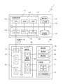
本実施形態に係る印刷システム1の構成について、図1、図2を参照して説明する。
なお、図面に付記する座標においては、Z軸方向が上下方向、+Z方向が上方向、X軸方向が前後方向、-X方向が前方向、Y軸方向が左右方向、+Y方向が左方向、X-Y平面が水平面としている。
1.
The configuration of a
In the coordinate system shown in the drawings, the Z-axis direction is the up-down direction, the +Z direction is the upward direction, the X-axis direction is the forward-backward direction, the -X direction is the forward direction, the Y-axis direction is the left-right direction, the +Y direction is the leftward direction, and the X-Y plane is the horizontal plane.
印刷システム1は、印刷装置としてのプリンター100、および、プリンター100に接続される画像処理装置としてのパーソナルコンピューター110によって構成されている。パーソナルコンピューター110は、以下、PC110と言う。
プリンター100は、PC110から受信する印刷データに基づいて、ロール状に巻かれた状態でセットされる長尺状の印刷媒体5に所望の画像を印刷するインクジェットプリンターである。
The
The
PC110は、印刷制御部111、入力部112、表示部113、記憶部114などを備え、プリンター100に印刷を行わせる印刷ジョブの制御を行う。また、PC110は、画像データに基づく所望の画像の印刷をプリンター100に実行させるための印刷データを生成する。
PC110が動作するソフトウェアには、印刷する画像データを扱う一般的な画像処理アプリケーションソフトウェアや、プリンター100の制御や、プリンター100に印刷を実行させるための印刷データを生成するプリンタードライバーソフトウェアが含まれる。以下の説明では、画像処理アプリケーションソフトウェアを単に画像処理アプリケーションと言う。また、プリンタードライバーソフトウェアを単にプリンタードライバーと言う。
ここで、画像データとは、テキストデータやフルカラーのイメージデータなども含むRGBのデジタル画像情報である。
The PC 110 includes a
The software that runs on the PC 110 includes general image processing application software that handles image data to be printed, and printer driver software that controls the
Here, image data refers to RGB digital image information including text data and full-color image data.
印刷制御部111は、CPU115や、ASIC116、DSP117、メモリー118、プリンターインターフェイス119、汎用インターフェイス120などを備え、印刷システム1全体の集中管理を行う。CPUは、Central Processing Unit、ASICは、Application Specific Integrated Circuit、DSPは、Digital Signal Processorを意味する。
入力部112は、ユーザーインターフェイスとしての情報入力手段である。具体的には、例えば、キーボードやマウスポインターなどである。
表示部113は、ユーザーインターフェイスとしての情報表示手段であり、印刷制御部111の制御の基に、入力部112から入力される情報や、プリンター100に印刷する画像、印刷ジョブに関係する情報などが表示される。
The
The
The
記憶部114は、ハードディスクドライブやメモリーカードなどの書き換え可能な記憶媒体であり、PC110が動作するソフトウェアとしての印刷制御部111で動作するプログラムや、印刷する画像、印刷ジョブに関係する情報などが記憶される。
メモリー118は、CPU115が動作するプログラムを格納する領域や動作する作業領域などを確保する記憶媒体であり、RAM、EEPROMなどの記憶素子によって構成される。RAMは、Random access memory、EEPROMは、Electrically Erasable Programmable Read-Only Memoryを意味する。
汎用インターフェイス120は、例えば、LANインターフェイスやUSBインターフェイスなど、外部電子機器を接続できるインターフェイスである。LANは、Local Area Network、USBは、Universal Serial Busを意味する。
The
The
The general-
プリンター100は、印刷部10、移動部20、プリンター制御部30などから構成されている。PC110から印刷データを受信したプリンター100は、印刷データに基づき、プリンター制御部30によって印刷部10、移動部20を制御し、印刷媒体5に画像を印刷する。
印刷データは、画像データを、PC110が備える画像処理アプリケーションおよびプリンタードライバーによってプリンター100で印刷できるように変換処理した画像形成用のデータであり、プリンター100を制御するコマンドを含んでいる。
The
The print data is data for image formation that has been converted and processed by an image processing application and printer driver included in the PC 110 so that the image data can be printed by the
印刷部10は、ヘッドユニット11、インク供給部12などから構成されている。
移動部20は、走査部40、搬送部50などから構成されている。
走査部40は、キャリッジ41、ガイド軸42、キャリッジモーターなどから構成されている。キャリッジモーターは、図示を省略している。
搬送部50は、供給部51、収納部52、搬送ローラー53、プラテン55などから構成されている。
The
The moving
The
The
ヘッドユニット11は、印刷用のインクをインク滴として吐出する複数のノズルを列設したノズル列を複数備える印刷ヘッド13およびヘッド制御部14を備えている。ヘッドユニット11は、キャリッジ41に搭載され、走査方向としてのX軸方向に移動するキャリッジ41に伴ってX軸方向に往復移動する。
The
インク供給部12は、インクタンクおよびインクタンクから印刷ヘッド13にインクを供給するインク供給路などを備えている。インクタンクおよびインク供給路については、図示を省略する。
インクには、シアン、マゼンタ、イエローの3色のインクセットにブラックを加えた4色のインクセットを用いている。
インクタンク、インク供給路、および同一インクを吐出するノズルまでのインク供給経路は、インクごとに独立して設けられている。
The
The ink used is a four-color ink set consisting of a three-color ink set of cyan, magenta, and yellow, plus black.
The ink tank, the ink supply passage, and the ink supply path to the nozzles that eject the same ink are provided independently for each ink.
インク滴を吐出するインクジェット方式には、ピエゾ方式を用いている。ピエゾ方式は、圧力発生室に貯留されたインクに、圧電素子としてのピエゾ素子を利用したアクチュエーターにより印刷情報信号に応じた圧力を加え、圧力発生室に連通するノズルからインク滴を噴射し印刷する方式である。
なお、インク滴を吐出する方式は、これに限定するものではなく、インクを液滴状に噴射させ、印刷媒体5上にドット群を形成する他の印刷方式であってもよい。
The inkjet method for ejecting ink droplets uses the piezoelectric method, which applies pressure to ink stored in a pressure generating chamber according to print information signals using an actuator that uses a piezoelectric element as a piezoelectric element, and then ejects ink droplets from a nozzle that communicates with the pressure generating chamber to print.
The method of ejecting ink droplets is not limited to this, and other printing methods that eject ink in the form of droplets to form dots on the
移動部20、つまり走査部40および搬送部50は、プリンター制御部30の制御の下に、印刷媒体5を印刷ヘッド13に対し相対移動させる。
ガイド軸42は、X軸方向に延在してキャリッジ41を摺接可能な状態で支持する。また、キャリッジモーターは、キャリッジ41をガイド軸42に沿って往復移動させる際の駆動源となる。つまり、走査部40は、プリンター制御部30の制御の下にキャリッジ41を、つまりは、印刷ヘッド13をガイド軸42に沿ってX軸方向に移動させる。キャリッジ41に搭載されたヘッドユニット11に備えられた印刷ヘッド13が、X軸方向に移動しながらプリンター制御部30の制御の下に、プラテン55に支持される印刷媒体5にインク滴を吐出することによって、X軸方向に沿った複数のドット列が印刷媒体5に形成される。
The
The guide shaft 42 extends in the X-axis direction and supports the carriage 41 in a slidable state. The carriage motor serves as a drive source for moving the carriage 41 back and forth along the guide shaft 42. In other words, the
供給部51は、印刷媒体5がロール状に巻かれたリールを回転可能に支持し、印刷媒体5を搬送経路に送り出す。収納部52は、印刷媒体5を巻き取るリールを回転可能に支持し、印刷が完了した印刷媒体5を搬送経路から巻き取る。
搬送ローラー53は、プラテン55の上面において印刷媒体5を搬送方向としてのY軸方向に移動させる駆動ローラーや印刷媒体5の移動に伴って回転する従動ローラーなどから成り、印刷媒体5を供給部51から印刷部10の印刷領域を経由し、収納部52に搬送する搬送経路を構成する。印刷領域は、プラテン55の上面で印刷ヘッド13がX軸方向に移動する領域である。
The
The
プリンター制御部30は、インターフェイス31、CPU32、メモリー33、駆動制御部34などを備え、プリンター100の制御を行う。
インターフェイス31は、PC110のプリンターインターフェイス119に接続され、PC110とプリンター100との間でデータの送受信を行う。
CPU32は、プリンター100全体の制御を行うための演算処理装置である。
メモリー33は、CPU32が動作するプログラムを格納する領域や動作する作業領域などを確保する記憶媒体であり、RAM、EEPROMなどの記憶素子によって構成される。
CPU32は、メモリー33に格納されているプログラム、およびPC110から受信した印刷データに従って、駆動制御部34を介して印刷部10、移動部20を制御する。
The
The
The
The
The
駆動制御部34は、CPU32の制御に基づいて動作するファームウェアを含み、印刷部10のヘッドユニット11、インク供給部12や、移動部20の走査部40、搬送部50の駆動を制御する。駆動制御部34は、移動制御信号生成回路35、吐出制御信号生成回路36、駆動信号生成回路37などを含む駆動制御回路、これら駆動制御回路を制御するファームウェアを内蔵するROMやフラッシュメモリーなどから構成されている。駆動制御回路を制御するファームウェアを内蔵するROMやフラッシュメモリーについては、図示を省略している。ここで、ROMは、Read-Only Memoryを意味する。
The
移動制御信号生成回路35は、印刷データに基づき、CPU32からの指示に従って、移動部20の走査部40や搬送部50を制御する信号を生成する回路である。
吐出制御信号生成回路36は、印刷データに基づき、CPU32からの指示に従って、インクを吐出するノズルの選択、吐出する量の選択、吐出するタイミングの制御などをするためのヘッド制御信号を生成する回路である。
駆動信号生成回路37は、印刷ヘッド13が備える圧力発生室を駆動する駆動信号を生成する回路である。
The movement control
The ejection control
The drive
図3を参照して、印刷ヘッド13の構成の例を説明する。
印刷ヘッド13は、インクを吐出する複数のノズル74が並んで形成されたブラックインクノズル列K、シアンインクノズル列C、マゼンタインクノズル列M、イエローインクノズル列Y、を備えている。各ノズル列の複数のノズル74は、搬送方向、つまりY軸方向に沿って、一定の間隔でそれぞれ整列して並んでいる。
An example of the configuration of the
The
以上の構成により、プリンター制御部30は、供給部51、搬送ローラー53によって印刷領域に供給された印刷媒体5に対し、ガイド軸42に沿って印刷ヘッド13を支持するキャリッジ41をX軸方向移動させながら印刷ヘッド13からインク滴を吐出する動作と、搬送ローラー53によりX軸方向と交差する+Y方向に印刷媒体5を移動させる動作とを繰り返すことにより、印刷媒体5に所望の画像を印刷する。
With the above configuration, the
印刷媒体5への印刷は、PC110からプリンター100に印刷データが送信されることにより開始される。印刷データは、プリンタードライバーによって生成される。
以下、プリンタードライバーが行う印刷データの生成処理について、図4を参照しながら説明する。
Printing onto the
The print data generation process performed by the printer driver will be described below with reference to FIG.
プリンタードライバーは、画像処理アプリケーションから画像データを受け取り、プリンター100が解釈できる形式の印刷データに変換し、印刷データをプリンター100に出力する。画像処理アプリケーションからの画像データを印刷データに変換する際に、プリンタードライバーは、解像度変換処理、色変換処理、ハーフトーン処理、ラスターライズ処理、コマンド付加処理などを行う。
The printer driver receives image data from the image processing application, converts it into print data in a format that can be interpreted by the
解像度変換処理は、画像処理アプリケーションから出力された画像データを、印刷媒体5に印刷する際の解像度に変換する処理である。例えば、印刷する際の解像度が720×720dpiに指定されている場合、画像処理アプリケーションから受け取ったベクター形式の画像データを720×720dpiの解像度のビットマップ形式の画像データに変換する。解像度変換処理後の画像データの各画素データは、マトリクス状に配置された画素から構成されている。各画素はRGB色空間の例えば256階調の階調値を有している。つまり、解像度変換後の画素データは、対応する画素の階調値を示すものである。
マトリクス状に配置された画素の内の、所定の方向に並ぶ1列分の画素に対応する画素データをラスターデータと言う。なお、ラスターデータに対応する画素が並ぶ所定の方向は、画像を印刷するときの印刷ヘッド13の移動方向、具体的にはX軸方向と対応している。印刷ヘッド13の移動方向は、すなわち、印刷ヘッド13と印刷媒体5とが相対的に移動する相対移動方向である。
The resolution conversion process is a process of converting image data output from an image processing application into a resolution for printing on the
Among the pixels arranged in a matrix, pixel data corresponding to one row of pixels aligned in a specific direction is called raster data. The specific direction in which the pixels corresponding to the raster data are aligned corresponds to the movement direction of the
色変換処理は、RGBデータをCMYK色系空間のデータに変換する処理である。CMYK色とは、シアン、マゼンタ、イエロー、ブラックであり、CMYK色系空間の画像データは、プリンター100が有するインクの色に対応したデータである。従って、例えば、プリンター100がCMYK色系の4種類のインクを使用する場合には、プリンタードライバーは、RGBデータに基づいて、CMYK色系の4次元空間の画像データを生成する。
この色変換処理は、RGBデータの階調値とCMYK色系データの階調値とを対応づけた色変換ルックアップテーブルに基づいて行われる。なお、色変換処理後の画素データは、CMYK色系空間により表される例えば256階調のCMYK色系データである。
The color conversion process is a process of converting RGB data into data in the CMYK color space. The CMYK colors are cyan, magenta, yellow, and black, and the image data in the CMYK color space is data corresponding to the colors of the inks in the
This color conversion process is performed based on a color conversion lookup table that associates the gradation values of RGB data with the gradation values of CMYK color system data. Note that the pixel data after the color conversion process is CMYK color system data of, for example, 256 gradations represented in the CMYK color system space.
ハーフトーン処理は、高階調数のデータ、例えば256階調のデータを、プリンター100が形成可能な階調数のデータに変換する処理である。このハーフトーン処理により、256階調を示すデータが、例えば、ドット有り、無しの2階調を示す1ビットのハーフトーンデータや、ドット無し、小ドット、中ドット、大ドットの4階調を示す2ビットのハーフトーンデータに変換される。具体的には、0~255の階調値とドット生成率とが対応したドット生成率テーブルから、階調値に対応するドットの生成率を求める。階調値に対応して求められるドットの生成率は、例えば、4階調の場合は、ドット無し、小ドット、中ドット、大ドットのそれぞれの生成率が求められる。得られたそれぞれの生成率において、ディザ法・誤差拡散法などを利用して、ドットが分散して形成されるように画素データが作成される。
Halftone processing is a process that converts data with a high number of gradations, for example, data with 256 gradations, into data with a number of gradations that the
ラスターライズ処理は、マトリクス状に並ぶ上述の1ビットや2ビットの画素データを、印刷時のドット形成順序に従って並べ替える処理である。ラスターライズ処理には、ハーフトーン処理後の画素データによって構成される画像データを、印刷ヘッド13が移動しながらインク滴を吐出する各パスに割り付けるパス割り付け処理が含まれる。パス割り付けが完了すると、印刷画像を構成する各ラスターラインを形成する実際のノズルが割り付けられる。
Rasterization is a process in which the 1-bit or 2-bit pixel data, which is arranged in a matrix, is rearranged according to the order in which dots are formed during printing. Rasterization includes a pass allocation process in which image data composed of pixel data after halftone processing is assigned to each pass in which the
コマンド付加処理は、ラスターライズ処理されたデータに、印刷方式に応じたコマンドデータを付加する処理である。コマンドデータとしては、例えば印刷媒体5の搬送仕様に関わる搬送データなどがある。搬送仕様とは、例えば、プラテン55の上面における印刷媒体5の搬送方向への移動量や速度などである。
プリンタードライバーによる前記一連の処理は、CPU115の制御の元にASIC116およびDSP117によって行われ、印刷データ送信処理では、前記一連の処理で生成された印刷データが、プリンターインターフェイス119を介してプリンター100に送信される。
The command addition process is a process of adding command data corresponding to the printing method to the rasterized data. The command data includes, for example, transport data related to the transport specifications of the
The series of processes by the printer driver are performed by the
以上説明したプリンタードライバーの基本機能に加え、本実施形態のプリンタードライバーは、つまり、印刷システム1は、更に、インクの滲みによる印刷品質の低下を抑制する機能を備えている。
一般的な印刷では、インク滴によるドットが印刷媒体に吸収されることで印刷画像を印刷媒体に定着させているが、印刷媒体に、印刷媒体の吸収容量を超えた密度でインク滴を吐出し付与した場合や、印刷媒体が高い浸透性を有している場合には、インク滴の一部が着弾した位置を越えて、必要以上に広がってしまうことがある。これに対し、印刷システム1は、例えば、印刷媒体5の裏面にまでインクが滲んでしまうことや、印刷画像の輪郭を越えて必要以上にインクが滲んでしまうことを抑制するために、印刷媒体5に付与するインク量を減少させる機能、つまり、印刷画像の濃度を任意に薄く設定することができる機能を有している。また、印刷システム1は、印刷画像の濃度を薄く設定した場合に、所望の印刷イメージと異なってしまうことや、文字や罫線などの印刷画像の輪郭のシャープさが損なわれてしまうことを抑制するエッジ処理の機能を備えている。
以下に具体的に説明する。
In addition to the basic functions of the printer driver described above, the printer driver of this embodiment, that is, the
In general printing, the dots formed by the ink droplets are absorbed by the printing medium to fix the print image on the printing medium, but when ink droplets are discharged and applied to the printing medium at a density exceeding the absorption capacity of the printing medium, or when the printing medium has high permeability, some of the ink droplets may spread beyond the landing position more than necessary. In response to this, the
The specific details are explained below.
印刷システム1は、プリンタードライバーの機能として、印刷画像の印刷濃度の補正値として補正濃度の設定を受け付ける補正濃度設定機能、印刷画像の輪郭を構成するエッジ画素が含まれるエッジ画素領域とエッジ画素領域に囲まれる内部画素領域とを識別する画素領域識別機能、設定された補正濃度の値に基づいて、内部画素領域とエッジ画素領域の印刷濃度を設定する印刷濃度設定機能、および、設定されたそれぞれの印刷濃度に基づき、印刷データを生成する印刷データ生成機能を有している。
換言すると、これらの機能を活用した工程を含む画像処理方法として見た場合に、本実施形態の画像処理方法は、印刷画像の印刷濃度の補正値として補正濃度の設定を受け付ける補正濃度設定工程、印刷画像の輪郭を構成するエッジ画素が含まれるエッジ画素領域とエッジ画素領域に囲まれる内部画素領域とを識別する画素領域識別工程、設定された補正濃度の値に基づいて、内部画素領域とエッジ画素領域の印刷濃度を設定する印刷濃度設定工程、および、設定されたそれぞれの印刷濃度に基づき、印刷データを生成する印刷データ生成工程を含んでいる。
The
In other words, when viewed as an image processing method including steps utilizing these functions, the image processing method of this embodiment includes a correction density setting step of accepting a correction density setting as a correction value for the print density of the print image, a pixel area identification step of identifying edge pixel areas containing edge pixels that form the contour of the print image and internal pixel areas surrounded by the edge pixel areas, a print density setting step of setting the print densities of the internal pixel areas and the edge pixel areas based on the set correction density value, and a print data generation step of generating print data based on the respective set print densities.
補正濃度設定工程では、印刷の実行に際し、ユーザーから、印刷画像の印刷濃度の補正仕様の入力を受け付け、補正値として補正濃度を設定する。ユーザーから受け付ける補正仕様としては、数値としての補正濃度、補正前の印刷画像の印刷濃度に対する濃度比率、補正濃度に紐付けることが可能な印刷媒体5の仕様や印刷モードなどの情報を用いることができる。また、補正仕様を受け付け、補正値として補正濃度を設定する機能は、プリンタードライバーの機能として、表示部113に表示するユーザーインターフェイス画面を介し、入力部112からの入力を受け付けて処理することによって実現することができる。
In the correction density setting process, when printing is performed, input of correction specifications for the print density of the print image is accepted from the user, and the correction density is set as a correction value. The correction specifications accepted from the user can be information such as the correction density as a numerical value, the density ratio to the print density of the print image before correction, and the specifications and print mode of the
画素領域識別工程では、印刷対象の画像データに基づき、印刷画像の輪郭を構成するエッジ画素が含まれるエッジ画素領域を抽出して、エッジ画素領域に囲まれる内部画素領域とエッジ画素領域とを識別する。例えば、図5に示すように、印刷画像の例としての文字Tは、白丸で示すエッジ画素領域と、黒丸で示す内部画素領域とに識別することができる。エッジ画素領域を抽出する方法については、後述する。 In the pixel region identification process, edge pixel regions that include edge pixels that form the contour of the print image are extracted based on the image data of the print target, and the edge pixel regions are identified from the internal pixel regions surrounded by the edge pixel regions. For example, as shown in FIG. 5, the letter T as an example of a print image can be identified into edge pixel regions indicated by white circles and internal pixel regions indicated by black circles. The method of extracting edge pixel regions will be described later.
印刷濃度設定工程では、設定された補正濃度が所定の閾値濃度以上の場合に、内部画素領域の印刷濃度を補正濃度として設定し、また、エッジ処理として、エッジ画素領域の印刷濃度を補正濃度と異なる印刷濃度として設定する。
また、設定された補正濃度が所定の閾値濃度未満の場合に、内部画素領域の印刷濃度およびエッジ画素領域の印刷濃度を、補正濃度として設定する。つまり、設定された補正濃度が所定の閾値濃度未満の場合には、エッジ処理を行わない。
In the print density setting process, when the set correction density is equal to or greater than a predetermined threshold density, the print density of the internal pixel region is set as the correction density, and as edge processing, the print density of the edge pixel region is set as a print density different from the correction density.
Furthermore, if the set correction density is less than a predetermined threshold density, the print density of the internal pixel region and the print density of the edge pixel region are set as the correction density, i.e., if the set correction density is less than a predetermined threshold density, edge processing is not performed.
ここで、所定の閾値濃度とは、予め設定された印刷濃度の値であり、エッジ処理を実施するか否かを判定するための閾値である。
例えば、印刷媒体5の裏面へのインクの滲みを抑制する目的で印刷画像を薄く補正する際、印刷画像の輪郭のシャープさが損なわれてしまうことを抑制するためにエッジ画素領域のみ濃度を補正しないようにするエッジ処理を行う場合に、印刷画像の濃度を薄くする度合いによっては、このエッジ処理によってエッジ画素領域の濃度が相対的に濃くなり、輪郭が縁取りされたイメージとなってしまうことがあった。これに対して、所定の閾値濃度より薄い補正が行われる場合においては、エッジ処理が行われないため、所定の閾値濃度を適切に設定することで、輪郭が縁取りされたイメージとなってしまうことが無くなる。あるいは抑制される。
また、例えば、印刷画像の輪郭の滲みによる印刷品質の低下を抑制するために、エッジ画素領域の濃度を内部画素領域の濃度より薄く補正するエッジ処理を行う場合に、印刷画像の濃度を薄くする度合いによっては、このエッジ処理によって輪郭線を形成する画素の階調値がより低くなることで、輪郭位置に形成されるドットが間引かれて、シャープな輪郭の印刷ができなくなってしまうことがあった。これに対して、所定の閾値濃度より薄い補正が行われる場合においては、エッジ処理が行われないため、所定の閾値濃度を適切に設定することで、輪郭位置に形成されるドットが間引かれて、シャープな輪郭の印刷ができなくなってしまうことが無くなる。あるいは抑制される。
Here, the predetermined threshold density is a preset print density value, which is a threshold for determining whether or not edge processing is to be performed.
For example, when a print image is corrected to be lighter in order to prevent ink bleeding onto the back side of the
Also, for example, when performing edge processing to correct the density of the edge pixel area to be lighter than the density of the internal pixel area in order to suppress deterioration of print quality due to bleeding of the contour of the printed image, depending on the degree to which the density of the printed image is lightened, the gradation value of the pixels forming the contour line becomes lower due to this edge processing, and dots formed at the contour position are thinned out, making it impossible to print a sharp contour. On the other hand, when correction is performed to be lighter than a predetermined threshold density, edge processing is not performed, so by appropriately setting the predetermined threshold density, thinning out dots formed at the contour position and making it impossible to print a sharp contour is prevented or suppressed.
このように、所定の閾値濃度は、印刷品質に影響するパラメーターであるため、予め、充分な評価の下に設定しておくことが好ましい。なお、輪郭が縁取りされたイメージとなってしまうことに対する許容レベルや、輪郭位置に形成されるドットが間引かれて、シャープな輪郭の印刷ができなくなってしまうことに対する許容レベルは、印刷画像の種類や目的、ユーザーの好みなどによって異なってくるため、所定の閾値濃度は、ユーザーの指定によって変更できるようにしても良い。ユーザーによる指定は、例えば、プリンタードライバーの機能として表示部113に表示されるユーザーインターフェイス画面を介し、入力部112から入力できるようにする。
As such, since the predetermined threshold density is a parameter that affects print quality, it is preferable to set it in advance after sufficient evaluation. Note that the tolerance level for an image with outlined edges and the tolerance level for dots formed at the outline position being thinned out, making it impossible to print sharp outlines, differ depending on the type and purpose of the print image, user preferences, etc., so the predetermined threshold density may be changed by user specification. The user specification can be made to be input from the
印刷データ生成工程では、印刷濃度設定工程で設定された内部画素領域およびエッジ画素領域の印刷濃度に基づき、印刷データを生成する。印刷濃度設定工程で設定された内部画素領域およびエッジ画素領域の印刷濃度に基づき生成された印刷データにより印刷を実行することで、印刷濃度の補正が行われ、インクの滲みが抑制された印刷においても、印刷品質の低下が抑制された印刷を行うことが可能となる。
以下、更に具体的について説明する。
In the print data generating step, print data is generated based on the print densities of the internal pixel region and the edge pixel region set in the print density setting step. By executing printing using the print data generated based on the print densities of the internal pixel region and the edge pixel region set in the print density setting step, the print density is corrected, and it becomes possible to perform printing with suppressed deterioration of print quality even in printing with suppressed ink bleeding.
A more specific explanation will be given below.
まず、図6を参照し、エッジ画素領域を抽出するエッジ抽出処理について説明する。
エッジ抽出処理は、例えば、文字や線画などの印刷画像の輪郭を構成するエッジ画素を画像データに基づき抽出し、エッジ処理の対象とするエッジ画素領域を抽出する処理である。
エッジ抽出処理は、印刷画像G1に対応する画像データD1に基づき印刷画像G1の輪郭を構成するエッジ画素が含まれるエッジ画素領域を抽出する。
エッジ抽出処理では、図6に示すように、まず、印刷画像G1のRGBの画像データに対して、レッドR、グリーンG、ブルーBのチャンネルに分解し、チャンネル毎にエッジ画素Rf、エッジ画素Gf、エッジ画素Bfを抽出する。エッジ画素抽出のアルゴリズムについては後述する。
次に、それぞれのチャンネルにおいてエッジ画素と判定された位置の画素をマージし、その結果を印刷画像G1のエッジ画素RGBfとして抽出する。
First, the edge extraction process for extracting edge pixel regions will be described with reference to FIG.
Edge extraction processing is processing that extracts edge pixels that form the contours of a print image, such as characters or line drawings, based on image data, and extracts edge pixel regions that are targets of edge processing.
The edge extraction process extracts an edge pixel area that includes edge pixels that form the contour of the print image G1 based on image data D1 that corresponds to the print image G1.
6, the edge extraction process first separates the RGB image data of the print image G1 into red R, green G, and blue B channels, and extracts edge pixels Rf, Gf, and Bf for each channel. The algorithm for edge pixel extraction will be described later.
Next, the pixels at positions determined to be edge pixels in each channel are merged, and the result is extracted as edge pixels RGBf of the print image G1.
次に、エッジ抽出処理で抽出されたエッジ画素RGBfに対して、引き続くエッジ処理の対象とするエッジ画素領域RGBmを決定する。抽出されたエッジ画素RGBfに対してエッジ処理を行う対象範囲としてのエッジ画素領域RGBmは、エッジ画素RGBfを中心とした周囲の画素範囲を、エッジ画素RGBfから離れる画素ピッチの数として予め設定しておく。エッジ画素RGBfから離れる画素ピッチの数を0とした場合には、エッジ画素RGBf=エッジ画素領域RGBmとなる。
エッジ画素領域RGBmの範囲を指定するピッチ数は、印刷媒体5に使用される材料やインクの特性に対応させて予め充分な評価を行った結果として適切に定めておくことが好ましいが、ユーザーの指定によって変更できるようにしても良い。ユーザーによる指定は、例えば、プリンタードライバーの機能として表示部113に表示されるユーザーインターフェイス画面を介し、入力部112から入力できるようにする。
図5に示す例は、印刷画像の例としての文字Tを、エッジ画素RGBfから離れる画素ピッチの数を0とした場合、つまりエッジ画素=エッジ画素領域として、白丸で示すエッジ画素領域と、黒丸で示す内部画素領域とに識別した結果の例を示している。
Next, an edge pixel region RGBm to be the target of subsequent edge processing is determined for the edge pixels RGBf extracted in the edge extraction process. The edge pixel region RGBm, which is the target range for edge processing of the extracted edge pixels RGBf, is preset as a surrounding pixel range centered on the edge pixel RGBf, as the number of pixel pitches away from the edge pixel RGBf. If the number of pixel pitches away from the edge pixel RGBf is set to 0, then edge pixel RGBf = edge pixel region RGBm.
The number of pitches specifying the range of the edge pixel region RGBm is preferably determined appropriately in advance as a result of sufficient evaluation in accordance with the characteristics of the material and ink used in the
The example shown in Figure 5 shows an example of the result when the letter T as an example of a printed image is classified into an edge pixel area indicated by a white circle and an internal pixel area indicated by a black circle, when the number of pixel pitches away from the edge pixel RGBf is set to 0, i.e., edge pixel = edge pixel area.
図7、図8を参照し、エッジ画素抽出のアルゴリズムについて説明する。
エッジ抽出処理は、エッジ画素か否かを判定する対象画素、つまり注目画素と、その周囲3×3画素の内の4画素の画像データ、具体的には濃度値である階調値、を用いて行う。なお、以下の説明では、階調値が大きいほど濃度が濃いものとする。
図7に示す3×3画素の内、画素0が注目画素、画素2,4,5,7が判定のための演算対象画素である。
The algorithm for extracting edge pixels will be described with reference to FIGS.
The edge extraction process is performed using the image data of the target pixel to be determined as an edge pixel, i.e., the pixel of interest, and four pixels out of the 3 x 3 pixels surrounding the pixel of interest, specifically, the gradation value, which is the density value. Note that in the following explanation, the larger the gradation value, the higher the density.
Of the 3×3 pixels shown in FIG. 7,
エッジ画素か否かの判定は、注目画素0の階調値と、その周囲の画素2,4,5,7の階調値との差異によって判定する。注目画素0と画素2,4,5,7のいずれかの画素の階調値との階調値の差が所定のエッジ判定閾値を上回り、また、注目画素0の階調値が所定のエッジ判定閾値を上回った周囲の画素の階調値より大きい場合に、注目画素0をエッジ画素と判定する。また、注目画素0の周囲に演算対象の画素2,4,5,7が揃わない端部画素の場合も、同様の演算が可能な周囲の画素の範囲で同様の判定を行う。
例えば、図8に示す例において、所定のエッジ判定閾値を90とした場合、注目画素0の階調値120に対して、周囲の画素2の階調値25との差異が95となるため、注目画素0はエッジ画素として判定される。
Whether or not a pixel of interest is an edge pixel is determined based on the difference between the gradation value of pixel of
For example, in the example shown in Figure 8, if the specified edge determination threshold is 90, the difference between the gradation value of the
エッジ画素の判定を行う際の所定のエッジ判定閾値は、予め適切な値として設定しておくことが好ましいが、ユーザーの指定によって変更できるようにしても良い。ユーザーによる指定は、例えば、プリンタードライバーの機能として表示部113に表示されるユーザーインターフェイス画面を介し、入力部112から入力できるようにする。
The predetermined edge determination threshold value used to determine edge pixels is preferably set to an appropriate value in advance, but may be changed by user specification. The user specification may be input from the
なお、エッジ画素領域を識別するためのエッジ抽出処理は、階調値の差異の度合いや階調値の分布により判定する方法であれば、上記に説明した方法に限定するものではない。例えば、注目画素0の周囲8画素を対象として演算を行う方法であっても良いし、より広い範囲における階調値の変化の傾きの度合いにより判定する方法であっても良い。また、印刷画像G1のRGBの画像データに対して行うのではなく、色変換処理後のCMYK色系の画像データに対して同様に行っても良い。
The edge extraction process for identifying edge pixel regions is not limited to the method described above, as long as it is a method that determines the degree of difference in gradation values or the distribution of gradation values. For example, it may be a method that performs calculations on eight pixels surrounding the
本実施形態では、具体的な実施例として、エッジ画素領域の印刷濃度を補正濃度と異なる印刷濃度として設定するエッジ処理の内、エッジ画素領域の印刷濃度を補正濃度より濃い印刷濃度として設定する場合について説明する。つまり、印刷濃度設定工程では、エッジ画素領域の印刷濃度を補正された内部画素領域の印刷濃度より濃い印刷濃度として設定する。
なお、以下の説明においては、補正前の印刷画像の印刷濃度をDb、補正濃度をDs、所定の閾値濃度をDt、印刷濃度設定工程で設定するエッジ画素領域の印刷濃度をDe、印刷濃度設定工程で設定する内部画素領域の印刷濃度をDiとする。
また、本実施形態における実施例を示す図9、図10は、および、後述する実施形態2における実施例を示す図12~図14は、横軸が、補正濃度Dsであり、縦軸が、印刷濃度設定後のエッジ画素領域の印刷濃度De、および、内部画素領域の印刷濃度Diである。印刷濃度の補正値として設定した補正濃度Dsと、補正濃度Dsに基づいて設定される内部画素領域の印刷濃度Diおよびエッジ画素領域の印刷濃度Deとの関係を示している。
In this embodiment, as a specific example, a case will be described in which the print density of the edge pixel region is set to a print density different from the correction density in edge processing, and the print density of the edge pixel region is set to a print density darker than the correction density. In other words, in the print density setting step, the print density of the edge pixel region is set to a print density darker than the corrected print density of the internal pixel region.
In the following explanation, the print density of the printed image before correction is Db, the corrected density is Ds, the specified threshold density is Dt, the print density of the edge pixel region set in the print density setting process is De, and the print density of the internal pixel region set in the print density setting process is Di.
9 and 10 showing examples of this embodiment, and 12 to 14 showing examples of a second embodiment described later, the horizontal axis is the correction density Ds, and the vertical axis is the print density De of the edge pixel region and the print density Di of the internal pixel region after the print density setting. The relationship between the correction density Ds set as the print density correction value and the print density Di of the internal pixel region and the print density De of the edge pixel region that are set based on the correction density Ds is shown.
1.1.実施例1
図9を参照して実施例1について説明する。
本実施例では、印刷濃度設定工程において、Ds<Dtの場合に、Di=De=Dsとし、Dt≦Ds<Dbの場合に、Di=Ds、De=Dbとしている。
つまり、印刷画像を薄く補正する補正濃度Dsを、所定の閾値濃度Dtより薄い濃度に設定した場合には、エッジ画素領域の印刷濃度Deと内部画素領域の印刷濃度Diとは、共に補正濃度Dsに設定される。つまりエッジ処理は行われない。
また、印刷画像を薄く補正する補正濃度Dsを、所定の閾値濃度Dt以上の濃い濃度に設定した場合には、エッジ画素領域の印刷濃度Deは、補正濃度Dsに補正された内部画素領域の印刷濃度Diに対して濃度の濃い、補正前の印刷画像の印刷濃度Dbのままに設定される。
Example 1
The first embodiment will be described with reference to FIG.
In this embodiment, in the print density setting process, when Ds<Dt, Di=De=Ds, and when Dt≦Ds<Db, Di=Ds, De=Db.
In other words, when the correction density Ds for correcting the print image to be lighter is set to a density lighter than a predetermined threshold density Dt, the print density De of the edge pixel region and the print density Di of the internal pixel region are both set to the correction density Ds, i.e., no edge processing is performed.
In addition, when the correction density Ds for correcting the printed image to be lighter is set to a density equal to or greater than a predetermined threshold density Dt, the print density De of the edge pixel region is set to the print density Db of the printed image before correction, which is darker than the print density Di of the internal pixel region corrected to the correction density Ds.
1.2.実施例2
図10を参照して実施例2について説明する。
本実施例では、エッジ画素領域の最大許容印刷濃度をDmaxとしたとき、印刷濃度設定工程では、Ds<Dtの場合、Di=De=Dsとし、Dt≦Ds<Dbの場合、De≦Dmaxにおいて、Di=Ds、De=(Ds-Dt)k+Dtとしている。また、算出されたDeがDmaxを越える場合にはDe=Dmaxとしている。ここで、係数kは、k>1である。
つまり、印刷画像を薄く補正する補正濃度Dsを、所定の閾値濃度Dtより薄い濃度に設定した場合には、エッジ画素領域の印刷濃度Deと内部画素領域の印刷濃度Diとは、共に補正濃度Dsに設定される。つまりエッジ処理は行われない。
また、印刷画像を薄く補正する補正濃度Dsを、所定の閾値濃度Dt以上の濃い濃度に設定した場合には、エッジ画素領域の印刷濃度Deは、最大許容印刷濃度Dmax以下の範囲において、補正濃度Dsに補正された内部画素領域の印刷濃度Diに対して、補正濃度Dsが高く設定されるほど濃い濃度になるように設定される。
Example 2
A second embodiment will be described with reference to FIG.
In this embodiment, when the maximum allowable print density of the edge pixel region is Dmax, in the print density setting process, if Ds<Dt, Di=De=Ds, and if Dt≦Ds<Db, Di=Ds, De=(Ds-Dt)k+Dt for De≦Dmax. Also, when the calculated De exceeds Dmax, De=Dmax. Here, the coefficient k is k>1.
In other words, when the correction density Ds for correcting the print image to be lighter is set to a density lighter than a predetermined threshold density Dt, the print density De of the edge pixel region and the print density Di of the internal pixel region are both set to the correction density Ds, i.e., no edge processing is performed.
In addition, when the correction density Ds for lightening the printed image is set to a density equal to or higher than a predetermined threshold density Dt, the print density De of the edge pixel region is set to be darker as the correction density Ds is set higher relative to the print density Di of the internal pixel region corrected to the correction density Ds, within a range equal to or lower than the maximum allowable print density Dmax.
次に、図11に示すフローチャートを参照し、上述した画像処理方法を含む印刷方法について説明する。
まず、ステップS1として、印刷する画像データを取得する。具体的には、PC110において、画像処理アプリケーションの機能において、汎用インターフェイス120を介して、外部電子機器から、印刷対象の画像データを取得する。あるいは、予め取得し、記憶部114に記憶しておいた画像データの中から印刷対象の画像データを選択する。
次に、ステップS2として、印刷仕様を決定する。具体的には、画像処理アプリケーションやプリンタードライバーの機能において、表示部113に表示するユーザーインターフェイス画面を介し、入力部112からの入力を受け付け、印刷画像のサイズや解像度、および、鮮鋭度などの印刷モードを含む印刷仕様を決定する。
Next, a printing method including the above-mentioned image processing method will be described with reference to the flowchart shown in FIG.
First, in step S1, image data to be printed is acquired. Specifically, in the
Next, in step S2, print specifications are determined. Specifically, in the image processing application or printer driver function, input is accepted from
次に、ステップS3として、印刷画像の印刷濃度の補正値として補正濃度を設定する。具体的には、プリンタードライバーの機能において、表示部113に表示するユーザーインターフェイス画面を介し、入力部112から印刷画像の印刷濃度の補正仕様の入力を受け付け、補正値として補正濃度を設定する。ステップS3は、補正濃度設定工程である。
Next, in step S3, a correction density is set as a correction value for the print density of the printed image. Specifically, in the printer driver function, input of correction specifications for the print density of the printed image is accepted from the
次に、ステップS4として、プリンタードライバーの機能において、画像データの解像度変換処理を行い、ステップS5として、解像度変換処理が完了した画像データに基づき、印刷画像の輪郭を構成するエッジ画素が含まれるエッジ画素領域を抽出して、エッジ画素領域に囲まれる内部画素領域とエッジ画素領域とを識別する。ステップS5は、画素領域識別工程である。 Next, in step S4, the printer driver performs a resolution conversion process on the image data, and in step S5, based on the image data for which the resolution conversion process has been completed, an edge pixel area that includes edge pixels that form the contour of the print image is extracted, and the edge pixel area is identified from the internal pixel area surrounded by the edge pixel area. Step S5 is a pixel area identification process.
次に、ステップS6として、プリンタードライバーの機能において、設定された補正濃度の値、および所定の閾値濃度に基づいて、内部画素領域とエッジ画素領域の印刷濃度を設定する。ステップS6は、印刷濃度設定工程である。
次に、ステップS7として、プリンタードライバーの機能において、設定された内部画素領域とエッジ画素領域の印刷濃度のそれぞれの印刷濃度に基づき、印刷データを生成する。具体的には、図4に示すプリンタードライバーが行う印刷データの生成処理の内の、色変換処理からコマンド付加処理までの処理を行う。ステップS7は、印刷データを生成する印刷データ生成工程である。
次に、ステップS8として、プリンタードライバーの機能において、生成された印刷データをプリンター100に送信し、プリンター100は受信した印刷データに基づいて印刷を行う。ステップS8は、印刷データに基づいて印刷する工程である。
Next, in step S6, the printer driver function sets the print densities of the internal pixel regions and edge pixel regions based on the set correction density value and a predetermined threshold density. Step S6 is a print density setting step.
Next, in step S7, the printer driver generates print data based on the print densities of the set interior pixel area and edge pixel area. Specifically, the printer driver performs processes from color conversion to command addition in the print data generation process shown in Fig. 4. Step S7 is a print data generation process that generates print data.
Next, in step S8, the printer driver function transmits the generated print data to the
本実施形態によれば、以下の効果を得ることができる。
まず、本実施形態における画像処理方法によれば、印刷画像の印刷濃度を補正する場合において、補正濃度が、所定の閾値濃度と同じか所定の閾値濃度より濃い場合には、内部画素領域の印刷濃度を補正濃度として設定し、エッジ画素領域の印刷濃度を補正濃度と異なる印刷濃度として設定する。また、印刷画像の印刷濃度を補正する場合において、補正濃度が、所定の閾値濃度より薄い場合に、内部画素領域の印刷濃度およびエッジ画素領域の印刷濃度を、補正濃度として設定する。
つまり、例えば、印刷画像として、内部画素領域の印刷濃度の補正は行うが、エッジ画素領域の印刷濃度については補正を行わない、あるいは、エッジ画素領域の印刷濃度は、内部画素領域の補正濃度より濃い印刷濃度にする、などのエッジ処理を行うことで、印刷品質の低下を抑制する場合においては、補正濃度が、所定の閾値濃度より薄い場合に、このエッジ処理が行われない。その結果、予め、所定の閾値濃度を適切に設定しておくことで、補正濃度を薄く設定したことにより、エッジ処理によってエッジ画素領域の濃度が相対的に濃くなり、輪郭が縁取りされたイメージとなってしまうことが無くなる。あるいは抑制される。
According to this embodiment, the following effects can be obtained.
First, according to the image processing method of the present embodiment, when correcting the print density of a print image, if the correction density is equal to or darker than a predetermined threshold density, the print density of the internal pixel region is set as the correction density, and the print density of the edge pixel region is set as a print density different from the correction density. Also, when correcting the print density of a print image, if the correction density is lighter than the predetermined threshold density, the print density of the internal pixel region and the print density of the edge pixel region are set as the correction densities.
That is, for example, in the case of performing edge processing such as correcting the print density of the internal pixel region but not correcting the print density of the edge pixel region as the print image, or making the print density of the edge pixel region darker than the corrected density of the internal pixel region, in order to suppress deterioration of print quality, if the corrected density is lighter than a predetermined threshold density, this edge processing is not performed. As a result, by appropriately setting the predetermined threshold density in advance, the correction density is set to a light value, and thus the density of the edge pixel region becomes relatively dark due to edge processing, and an image with a bordered outline is prevented or suppressed.
また、本実施形態の実施例1および実施例2における印刷濃度設定工程では、補正濃度が、所定の閾値濃度と同じか所定の閾値濃度より濃い場合に、エッジ画素領域の印刷濃度を補正濃度より濃い印刷濃度として設定する。また、補正濃度が、所定の閾値濃度より薄い場合に、内部画素領域の印刷濃度およびエッジ画素領域の印刷濃度を、補正濃度として設定する。
つまり、エッジ画素領域の印刷濃度を内部画素領域の補正濃度より濃い印刷濃度にするエッジ処理を行うことで、印刷画像としての印刷品質の低下を抑制する場合においては、補正濃度が、所定の閾値濃度より薄い場合に、このエッジ処理が行われない。その結果、予め、所定の閾値濃度を適切に設定しておくことで、補正濃度を薄く設定したことにより、エッジ処理によってエッジ画素領域の濃度が相対的に濃くなり、輪郭が縁取りされたイメージとなってしまうことが無くなる。あるいは抑制される。
In the print density setting process in Examples 1 and 2 of this embodiment, when the correction density is equal to or greater than a predetermined threshold density, the print density of the edge pixel region is set to a print density greater than the correction density, and when the correction density is less than the predetermined threshold density, the print density of the interior pixel region and the print density of the edge pixel region are set to the correction density.
In other words, in the case of suppressing deterioration in print quality as a printed image by performing edge processing to make the print density of the edge pixel region darker than the correction density of the internal pixel region, this edge processing is not performed if the correction density is lighter than a predetermined threshold density. As a result, by appropriately setting the predetermined threshold density in advance, the correction density is set to a light value, and the density of the edge pixel region becomes relatively dark due to edge processing, which prevents or suppresses the image of a bordered outline.
また、本実施形態の実施例1によれば、Dt≦Ds<Dbの場合、Di=Ds、De=Dbであるため、内部画素領域を補正濃度Dsに薄くした場合に、エッジ画素領域の濃度を内部画素領域の濃度より濃くするエッジ処理を行うことができる。
また、Ds<Dtの場合、Di=De=Dsであるため、つまり、エッジ処理が行われないため、エッジ処理によってエッジ画素領域の濃度が相対的に濃くなり、輪郭が縁取りされたイメージとなってしまうことが無くなる。
Furthermore, according to Example 1 of this embodiment, when Dt≦Ds<Db, Di=Ds and De=Db, so when the internal pixel region is lightened to a corrected density Ds, edge processing can be performed to make the density of the edge pixel region darker than the density of the internal pixel region.
Furthermore, when Ds<Dt, Di=De=Ds, that is, no edge processing is performed, so the edge pixel area does not become relatively dark due to edge processing, resulting in an image with a bordered outline.
また、本実施形態の実施例2によれば、k>1、De≦Dmaxにおいて、Dt≦Ds<Dbの場合、Di=Ds、De=(Ds-Dt)k+Dtであるため、内部画素領域を補正濃度Dsに薄くした場合に、エッジ画素領域の濃度を内部画素領域の濃度より濃くするエッジ処理を行うことができる。また、この場合に、Dsを薄い濃度に設定するほどに、Deも薄くなる、つまり、所定の閾値濃度に近いほど、エッジ画素領域の濃度と内部画素領域の濃度との差が小さくなるため、エッジ処理によって輪郭が縁取りされたイメージとなってしまうことが抑制される。
また、k>1、Ds<Dtの場合、Di=De=Dsであるため、つまり、エッジ処理が行われないため、予め、所定の閾値濃度を適切に設定しておくことで、エッジ処理によってエッジ画素領域の濃度が相対的に濃くなり、輪郭が縁取りされたイメージとなってしまうことが無くなる。
According to Example 2 of this embodiment, when k>1 and De≦Dmax, if Dt≦Ds<Db, then Di=Ds and De=(Ds-Dt)k+Dt, so when the internal pixel region is lightened to the corrected density Ds, edge processing can be performed to make the density of the edge pixel region darker than the density of the internal pixel region. In this case, the lighter the density Ds is set to, the lighter De becomes, that is, the closer to a predetermined threshold density, the smaller the difference between the density of the edge pixel region and the density of the internal pixel region becomes, so that the edge processing is prevented from producing an image with a bordered outline.
Furthermore, when k>1 and Ds<Dt, Di=De=Ds, i.e., edge processing is not performed, so by appropriately setting a predetermined threshold density in advance, the density of the edge pixel area will not become relatively high due to edge processing, resulting in an image with a bordered outline.
また、本実施形態における印刷方法によれば、予め、所定の閾値濃度を適切に設定しておくことで、補正濃度を薄く設定したことによる印刷品質の低下が抑制された印刷を行うことができる。 In addition, according to the printing method of this embodiment, by appropriately setting a predetermined threshold density in advance, it is possible to perform printing that suppresses deterioration in print quality caused by setting the correction density to a low value.
また、本実施形態における印刷システム1によれば、予め、所定の閾値濃度を適切に設定しておくことで、補正濃度を薄く設定したことによる印刷品質の低下が抑制された印刷を行うことができる。
In addition, according to the
2.実施形態2
実施形態1では、実施例1、実施例2として、印刷濃度設定工程で、補正濃度が所定の閾値濃度以上の場合に、エッジ画素領域の印刷濃度を補正濃度より濃い印刷濃度として設定する場合について説明したが、本実施形態では、印刷濃度設定工程で、補正濃度が所定の閾値濃度以上の場合に、エッジ画素領域の印刷濃度を補正濃度より薄い印刷濃度として設定する場合について説明する。つまり、印刷濃度設定工程では、エッジ画素領域の印刷濃度を補正された内部画素領域の印刷濃度より薄い印刷濃度として設定する。
2.
In the first embodiment, examples 1 and 2 are described in which the print density setting step sets the print density of the edge pixel region to a print density darker than the correction density when the correction density is equal to or greater than a predetermined threshold density, but in the present embodiment, a case is described in which the print density setting step sets the print density of the edge pixel region to a print density lighter than the correction density when the correction density is equal to or greater than a predetermined threshold density. In other words, in the print density setting step, the print density of the edge pixel region is set to a print density lighter than the corrected print density of the internal pixel region.
2.1.実施例3
図12を参照して実施例3について説明する。
本実施例では、印刷濃度設定工程において、Ds<Dtの場合に、Di=De=Dsとし、Dt≦Ds<Dbの場合に、Di=Ds、De=Dtとしている。
つまり、印刷画像を薄く補正する補正濃度Dsを、所定の閾値濃度Dtより薄い濃度に設定した場合には、エッジ画素領域の印刷濃度Deと内部画素領域の印刷濃度Diとは、共に補正濃度Dsに設定される。つまりエッジ処理は行われない。
また、印刷画像を薄く補正する補正濃度Dsを、所定の閾値濃度Dt以上の濃い濃度に設定した場合には、エッジ画素領域の印刷濃度Deは、補正濃度Dsに補正された内部画素領域の印刷濃度Diに対して濃度の薄い、所定の閾値濃度Dtに設定される。
Example 3
A third embodiment will be described with reference to FIG.
In this embodiment, in the print density setting process, when Ds<Dt, Di=De=Ds, and when Dt≦Ds<Db, Di=Ds, De=Dt.
In other words, when the correction density Ds for correcting the print image to be lighter is set to a density lighter than a predetermined threshold density Dt, the print density De of the edge pixel region and the print density Di of the internal pixel region are both set to the correction density Ds, i.e., no edge processing is performed.
In addition, when the correction density Ds, which corrects the printed image to be lighter, is set to a density that is darker than a predetermined threshold density Dt, the print density De of the edge pixel region is set to the predetermined threshold density Dt, which is lighter than the print density Di of the internal pixel region corrected to the correction density Ds.
2.2.実施例4
図13を参照して実施例4について説明する。
本実施例では、印刷濃度設定工程では、Ds<Dtの場合、Di=De=Dsとし、Dt≦Ds<Dbの場合、Di=Ds、De=(Ds-Dt)k+Dtとしている。ここで、係数kは、0<k<1である。
つまり、印刷画像を薄く補正する補正濃度Dsを、所定の閾値濃度Dtより薄い濃度に設定した場合には、エッジ画素領域の印刷濃度Deと内部画素領域の印刷濃度Diとは、共に補正濃度Dsに設定される。つまりエッジ処理は行われない。
また、印刷画像を薄く補正する補正濃度Dsを、所定の閾値濃度Dt以上の濃い濃度に設定した場合には、エッジ画素領域の印刷濃度Deは、補正濃度Dsに補正された内部画素領域の印刷濃度Diに対して濃度が薄い範囲で、補正濃度Dsが高く設定されるほど、濃い濃度になるように設定される。
Example 4
A fourth embodiment will be described with reference to FIG.
In this embodiment, in the print density setting process, when Ds<Dt, Di=De=Ds, and when Dt≦Ds<Db, Di=Ds, De=(Ds−Dt)k+Dt, where the coefficient k is 0<k<1.
In other words, when the correction density Ds for correcting the print image to be lighter is set to a density lighter than a predetermined threshold density Dt, the print density De of the edge pixel region and the print density Di of the internal pixel region are both set to the correction density Ds, i.e., no edge processing is performed.
Furthermore, when the correction density Ds for lightening the print image is set to a density equal to or higher than a predetermined threshold density Dt, the print density De of the edge pixel region is set to a darker density as the correction density Ds is set higher within a range of lighter densities than the print density Di of the internal pixel region corrected to the correction density Ds.
2.3.実施例5
図14を参照して実施例5について説明する。
本実施例は、実施例3に対して、補正濃度Dsの設定が、補正前の印刷画像の印刷濃度Dbより濃い濃度に設定される場合を含めている。
本実施例では、印刷濃度設定工程において、Ds<Dtの場合に、Di=De=Dsとし、Dt≦Ds<Dbの場合に、Di=Ds、De=Dtとし、Db≦Dsの場合に、De=DsDt/Dbとしている。また、算出されたDeがDmaxを越える場合にはDe=Dmaxとしている。
つまり、印刷画像を薄く補正する補正濃度Dsを、所定の閾値濃度Dtより薄い濃度に設定した場合には、エッジ画素領域の印刷濃度Deと内部画素領域の印刷濃度Diとは、共に補正濃度Dsに設定される。つまりエッジ処理は行われない。
また、印刷画像を薄く補正する補正濃度Dsを、補正前の印刷画像の印刷濃度Dbより薄い範囲において、所定の閾値濃度Dt以上の濃い濃度に設定した場合には、エッジ画素領域の印刷濃度Deは、補正濃度Dsに補正された内部画素領域の印刷濃度Diに対して濃度の薄い、所定の閾値濃度Dtに設定される。
また、補正濃度Dsの設定を、補正前の印刷画像の印刷濃度Db以上の濃い濃度に設定した場合には、エッジ画素領域の印刷濃度Deは、最大許容印刷濃度Dmax以下の範囲において、補正濃度Dsに補正された内部画素領域の印刷濃度Diに対して濃度が薄い範囲で、補正濃度Dsが高く設定されるほど、濃い濃度になるように設定される。
Example 5
A fifth embodiment will be described with reference to FIG.
In contrast to the third embodiment, this embodiment includes a case where the correction density Ds is set to a density darker than the print density Db of the print image before correction.
In this embodiment, in the print density setting process, when Ds<Dt, Di=De=Ds, when Dt≦Ds<Db, Di=Ds, De=Dt, when Db≦Ds, De=DsDt/Db. Also, when the calculated De exceeds Dmax, De=Dmax.
In other words, when the correction density Ds for correcting the print image to be lighter is set to a density lighter than a predetermined threshold density Dt, the print density De of the edge pixel region and the print density Di of the internal pixel region are both set to the correction density Ds, i.e., no edge processing is performed.
In addition, when the correction density Ds for correcting the printed image to be lighter is set to a density equal to or greater than a predetermined threshold density Dt in a range lighter than the print density Db of the printed image before correction, the print density De of the edge pixel region is set to the predetermined threshold density Dt, which is lighter than the print density Di of the internal pixel region corrected to the correction density Ds.
Furthermore, when the correction density Ds is set to a density darker than the print density Db of the printed image before correction, the print density De of the edge pixel area is set to a density lighter than the print density Di of the internal pixel area corrected to the correction density Ds within a range below the maximum allowable print density Dmax, and the higher the correction density Ds is set, the darker the density becomes.
本実施形態によれば、以下の効果を得ることができる。
印刷画像の印刷濃度を補正する場合において、補正濃度が、所定の閾値濃度と同じか所定の閾値濃度より濃い場合には、内部画素領域の印刷濃度を補正濃度として設定し、エッジ画素領域の印刷濃度を補正濃度と異なる印刷濃度として設定する。また、印刷画像の印刷濃度を補正する場合において、補正濃度が、所定の閾値濃度より薄い場合に、内部画素領域の印刷濃度およびエッジ画素領域の印刷濃度を、補正濃度として設定する。
つまり、例えば、エッジ画素領域の印刷濃度を内部画素領域の補正濃度より薄い印刷濃度にするエッジ処理を行うことで、印刷品質の低下を抑制する場合においては、補正濃度が、所定の閾値濃度より薄い場合に、このエッジ処理が行われない。その結果、予め、所定の閾値濃度を適切に設定しておくことで、補正濃度を薄く設定したことにより、エッジ処理によって輪郭線を形成する画素の階調値が低くなり、輪郭位置に形成されるドットが間引かれて、シャープな輪郭の印刷ができなくなってしまうことが無くなる。あるいは抑制される。
According to this embodiment, the following effects can be obtained.
When correcting the print density of a print image, if the correction density is equal to or darker than a predetermined threshold density, the print density of the internal pixel region is set as the correction density, and the print density of the edge pixel region is set as a print density different from the correction density. Also, when correcting the print density of a print image, if the correction density is lighter than the predetermined threshold density, the print density of the internal pixel region and the print density of the edge pixel region are set as the correction densities.
That is, for example, in the case of suppressing deterioration in print quality by performing edge processing to make the print density of the edge pixel region lighter than the correction density of the internal pixel region, this edge processing is not performed if the correction density is lighter than a predetermined threshold density. As a result, by appropriately setting the predetermined threshold density in advance, the correction density is set to a light value, and the gradation value of the pixels forming the contour line by edge processing is lowered, and the dots formed at the contour position are thinned out, which prevents or suppresses the inability to print a sharp contour.
また、本実施形態の実施例3および実施例4における印刷濃度設定工程では、補正濃度が、所定の閾値濃度と同じか所定の閾値濃度より濃い場合に、エッジ画素領域の印刷濃度を補正濃度より薄い印刷濃度として設定する。また、補正濃度が、所定の閾値濃度より薄い場合に、内部画素領域の印刷濃度およびエッジ画素領域の印刷濃度を、補正濃度として設定する。
つまり、エッジ画素領域の印刷濃度を内部画素領域の補正濃度より薄い印刷濃度にするエッジ処理を行うことで、印刷画像としての印刷品質の低下を抑制する場合においては、補正濃度が、所定の閾値濃度より薄い場合に、このエッジ処理が行われない。その結果、予め、所定の閾値濃度を適切に設定しておくことで、補正濃度を薄く設定したことにより、エッジ処理によって輪郭線を形成する画素の階調値が低くなり、輪郭位置に形成されるドットが間引かれて、シャープな輪郭の印刷ができなくなってしまうことが無くなる。あるいは抑制される。
In the print density setting process in Examples 3 and 4 of this embodiment, when the correction density is equal to or greater than a predetermined threshold density, the print density of the edge pixel region is set to a print density less than the correction density, and when the correction density is less than the predetermined threshold density, the print densities of the interior pixel region and the edge pixel region are set to the correction densities.
In other words, in the case of suppressing deterioration in print quality as a printed image by performing edge processing to make the print density of the edge pixel region lighter than the correction density of the internal pixel region, this edge processing is not performed if the correction density is lighter than a predetermined threshold density. As a result, by appropriately setting the predetermined threshold density in advance, the correction density is set to a light value, and the gradation value of the pixels forming the contour line by edge processing is lowered, and the dots formed at the contour position are thinned out, which prevents or suppresses the inability to print a sharp contour.
また、本実施形態の実施例3によれば、Dt≦Ds<Dbの場合、Di=Ds、De=Dtであるため、内部画素領域を補正濃度Dsに薄くした場合に、エッジ画素領域の濃度を内部画素領域の濃度より薄くするエッジ処理を行うことができる。
また、Ds<Dtの場合、Di=De=Dsであるため、つまり、エッジ処理が行われないため、予め、所定の閾値濃度を適切に設定しておくことで、エッジ処理によって輪郭線を形成する画素の階調値が低くなり、輪郭位置に形成されるドットが間引かれて、シャープな輪郭の印刷ができなくなってしまうことが無くなる。
Furthermore, according to Example 3 of this embodiment, when Dt≦Ds<Db, Di=Ds and De=Dt, so when the internal pixel region is lightened to a corrected density Ds, edge processing can be performed to make the density of the edge pixel region lighter than the density of the internal pixel region.
Furthermore, when Ds<Dt, Di=De=Ds, that is, edge processing is not performed, so by appropriately setting a predetermined threshold density in advance, the gradation value of the pixels that form the contour line by edge processing is lowered, and the dots formed at the contour position are thinned out, preventing the printing of sharp contours.
また、本実施形態の実施例4によれば、k<1、Dt≦Ds<Dbの場合、Di=Ds、De=(Ds-Dt)k+Dtであるため、内部画素領域を補正濃度Dsに薄くした場合に、エッジ画素領域の濃度を内部画素領域の濃度より薄くするエッジ処理を行うことができる。
また、k<1、Ds<Dtの場合、Di=De=Dsであるため、つまり、エッジ処理が行われないため、予め、所定の閾値濃度を適切に設定しておくことで、エッジ処理によって輪郭線を形成する画素の階調値が低くなり、輪郭位置に形成されるドットが間引かれて、シャープな輪郭の印刷ができなくなってしまうことが無くなる。
Furthermore, according to Example 4 of this embodiment, when k<1 and Dt≦Ds<Db, Di=Ds and De=(Ds-Dt)k+Dt, so when the internal pixel region is lightened to a corrected density Ds, edge processing can be performed to make the density of the edge pixel region lighter than the density of the internal pixel region.
Furthermore, when k<1 and Ds<Dt, Di=De=Ds, that is, edge processing is not performed, so by appropriately setting a predetermined threshold density in advance, the gradation value of the pixels that form the contour line by edge processing is lowered, and the dots formed at the contour position are thinned out, preventing the printing of sharp contours.
また、本実施形態の実施例5によれば、実施例3に対して、補正濃度Dsの設定が、補正前の印刷画像の印刷濃度Dbより濃い濃度に設定される場合についても同様の効果を得ることができる。 Furthermore, according to Example 5 of this embodiment, the same effect can be obtained as in Example 3 even when the correction density Ds is set to a density darker than the print density Db of the print image before correction.
なお、印刷システム1は、印刷装置としてのプリンター100、および、プリンター100に接続される画像処理装置としてのパーソナルコンピューター110によって構成されていると述べたが、プリンター100にパーソナルコンピューター110の機能を備え、1台の印刷装置として印刷システム1を構成しても良い。
It has been stated that the
また、上述したエッジ抽出処理は、必ずしも、RGBやCMYK色系の画像データの階調値に基づいて判定する方法でなくとも良い。具体的には、例えば、ハーフトーン処理後の1ビットや2ビットのハーフトーンデータの分布から判定する方法であっても良い。
この場合、エッジ処理は、抽出されたエッジ画素領域としての1ビットや2ビットのハーフトーンデータに対して行う。具体的には、例えば、エッジ処理が、エッジ画素領域の印刷濃度を薄くする処理を行う処理の場合、ハーフトーンデータが、例えば、4階調、つまり、ドット無し、小ドット、中ドット、大ドットの複数のドットサイズを示す2ビット以上のデータで構成されている場合に、それぞれのハーフトーンデータを、1サイズ小さなドットに変換する。なお、小ドットの場合に1サイズ小さくするとは、ドット無しに変更することである。また、例えば、エッジ処理が、エッジ画素領域の印刷濃度を濃くする処理を行う処理の場合、ハーフトーンデータが、例えば、4階調、つまり、ドット無し、小ドット、中ドット、大ドットの複数のドットサイズを示す2ビット以上のデータで構成されている場合に、小ドット、中ドットのハーフトーンデータを、1サイズ大きなドットに変換する。
Furthermore, the above-mentioned edge extraction process does not necessarily have to be a method that is determined based on the gradation values of image data in the RGB or CMYK color system. Specifically, for example, it may be a method that is determined based on the distribution of 1-bit or 2-bit halftone data after halftone processing.
In this case, the edge processing is performed on 1-bit or 2-bit halftone data as the extracted edge pixel region. Specifically, for example, when the edge processing is a process for reducing the print density of the edge pixel region, and the halftone data is composed of, for example, four gradations, that is, data of 2 or more bits indicating a plurality of dot sizes, such as no dot, small dot, medium dot, and large dot, each halftone data is converted into a dot one size smaller. Note that, in the case of a small dot, reducing the size by one means changing to no dot. Also, for example, when the edge processing is a process for increasing the print density of the edge pixel region, and the halftone data is composed of, for example, four gradations, that is, data of 2 or more bits indicating a plurality of dot sizes, such as no dot, small dot, medium dot, and large dot, each halftone data of a small dot and a medium dot is converted into a dot one size larger.
1…印刷システム、5…印刷媒体、10…印刷部、11…ヘッドユニット、12…インク供給部、13…印刷ヘッド、14…ヘッド制御部、20…移動部、30…プリンター制御部、31…インターフェイス、32…CPU、33…メモリー、34…駆動制御部、35…移動制御信号生成回路、36…吐出制御信号生成回路、37…駆動信号生成回路、40…走査部、41…キャリッジ、42…ガイド軸、50…搬送部、51…供給部、52…収納部、53…搬送ローラー、55…プラテン、74…ノズル、100…プリンター、110…パーソナルコンピューター、111…印刷制御部、112…入力部、113…表示部、114…記憶部、115…CPU、116…ASIC、117…DSP、118…メモリー、119…プリンターインターフェイス、120…汎用インターフェイス、D1…画像データ、G1…印刷画像。 1...printing system, 5...printing medium, 10...printing section, 11...head unit, 12...ink supply section, 13...print head, 14...head control section, 20...movement section, 30...printer control section, 31...interface, 32...CPU, 33...memory, 34...drive control section, 35...movement control signal generating circuit, 36...ejection control signal generating circuit, 37...drive signal generating circuit, 40...scanning section, 41...carriage, 42...guide shaft, 50...transport section, 51...supply section, 52...storage section, 53...transport roller, 55...platen, 74...nozzle, 100...printer, 110...personal computer, 111...printing control section, 112...input section, 113...display section, 114...storage section, 115...CPU, 116...ASIC, 117...DSP, 118...memory, 119...printer interface, 120...general purpose interface, D1...image data, G1...printed image.
Claims (5)
前記印刷画像の印刷濃度の補正値として補正濃度を設定する補正濃度設定工程と、
前記画像データに基づき、前記印刷画像の輪郭を構成するエッジ画素が含まれるエッジ画素領域を抽出して、前記エッジ画素領域に囲まれる内部画素領域と前記エッジ画素領域とを識別する画素領域識別工程と、
前記補正濃度が所定の閾値濃度以上の場合に、前記内部画素領域の印刷濃度を前記補正濃度として設定し、また、前記エッジ画素領域の印刷濃度を前記補正濃度と異なる印刷濃度として設定し、前記補正濃度が前記所定の閾値濃度未満の場合に、前記内部画素領域の印刷濃度および前記エッジ画素領域の印刷濃度を、前記補正濃度として設定する印刷濃度設定工程と、
前記印刷濃度設定工程で設定された印刷濃度に基づき、前記印刷データを生成する印刷データ生成工程と、を含み、
補正前の前記印刷画像の印刷濃度をDb、
前記補正濃度をDs、
前記所定の閾値濃度をDt、
前記印刷濃度設定工程で設定する前記エッジ画素領域の印刷濃度をDe、
前記印刷濃度設定工程で設定する前記内部画素領域の印刷濃度をDi、としたとき、
Dt≦Ds<Dbの場合、Di=Ds、De=Db、
Ds<Dtの場合、Di=De=Dsである画像処理方法。 1. An image processing method for generating print data for causing a printing device to execute printing with corrected print density of a print image based on image data, comprising:
a correction density setting step of setting a correction density as a correction value for the print density of the print image;
a pixel region identification step of extracting an edge pixel region including edge pixels that form the contour of the print image based on the image data, and identifying the edge pixel region from an internal pixel region surrounded by the edge pixel region;
a print density setting step of setting the print density of the internal pixel region as the correction density when the correction density is equal to or greater than a predetermined threshold density, and setting the print density of the edge pixel region as a print density different from the correction density, and setting the print density of the internal pixel region and the print density of the edge pixel region as the correction density when the correction density is less than the predetermined threshold density;
a print data generating step of generating the print data based on the print density set in the print density setting step ,
The print density of the printed image before correction is Db,
The corrected density is Ds,
The predetermined threshold density is Dt,
The print density of the edge pixel region set in the print density setting step is De,
When the print density of the internal pixel region set in the print density setting step is Di,
If Dt≦Ds<Db, Di=Ds, De=Db,
An image processing method in which Di=De=Ds if Ds<Dt .
前記印刷画像の印刷濃度の補正値として補正濃度を設定する補正濃度設定工程と、
前記画像データに基づき、前記印刷画像の輪郭を構成するエッジ画素が含まれるエッジ画素領域を抽出して、前記エッジ画素領域に囲まれる内部画素領域と前記エッジ画素領域とを識別する画素領域識別工程と、
前記補正濃度が所定の閾値濃度以上の場合に、前記内部画素領域の印刷濃度を前記補正濃度として設定し、また、前記エッジ画素領域の印刷濃度を前記補正濃度と異なる印刷濃度として設定し、前記補正濃度が前記所定の閾値濃度未満の場合に、前記内部画素領域の印刷濃度および前記エッジ画素領域の印刷濃度を、前記補正濃度として設定する印刷濃度設定工程と、
前記印刷濃度設定工程で設定された印刷濃度に基づき、前記印刷データを生成する印刷データ生成工程と、を含み、
補正前の前記印刷画像の印刷濃度をDb、
前記補正濃度をDs、
前記所定の閾値濃度をDt、
前記印刷濃度設定工程で設定する前記エッジ画素領域の印刷濃度をDe、
前記エッジ画素領域の最大許容印刷濃度をDmax、
前記印刷濃度設定工程で設定する前記内部画素領域の印刷濃度をDi、
係数をk、としたとき、
De≦Dmaxにおいて、
Dt≦Ds<Dbの場合、Di=Ds、De=(Ds-Dt)k+Dt、
Ds<Dtの場合、Di=De=Dsである画像処理方法。 1. An image processing method for generating print data for causing a printing device to execute printing with corrected print density of a print image based on image data, comprising:
a correction density setting step of setting a correction density as a correction value for the print density of the print image;
a pixel region identification step of extracting an edge pixel region including edge pixels that form the contour of the print image based on the image data, and identifying the edge pixel region from an internal pixel region surrounded by the edge pixel region;
a print density setting step of setting the print density of the internal pixel region as the correction density when the correction density is equal to or greater than a predetermined threshold density, and setting the print density of the edge pixel region as a print density different from the correction density, and setting the print density of the internal pixel region and the print density of the edge pixel region as the correction density when the correction density is less than the predetermined threshold density;
a print data generating step of generating the print data based on the print density set in the print density setting step,
The print density of the printed image before correction is Db,
The corrected density is Ds,
The predetermined threshold density is Dt,
The print density of the edge pixel region set in the print density setting step is De,
The maximum allowable print density of the edge pixel region is Dmax,
The print density of the internal pixel region set in the print density setting step is Di,
When the coefficient is k,
In the case where De≦Dmax,
If Dt≦Ds<Db, Di=Ds, De=(Ds−Dt)k+Dt,
An image processing method in which Di=De=Ds if Ds<Dt.
前記印刷画像の印刷濃度の補正値として補正濃度を設定する補正濃度設定工程と、
前記画像データに基づき、前記印刷画像の輪郭を構成するエッジ画素が含まれるエッジ画素領域を抽出して、前記エッジ画素領域に囲まれる内部画素領域と前記エッジ画素領域とを識別する画素領域識別工程と、
前記補正濃度が所定の閾値濃度以上の場合に、前記内部画素領域の印刷濃度を前記補正濃度として設定し、また、前記エッジ画素領域の印刷濃度を前記補正濃度と異なる印刷濃度として設定し、前記補正濃度が前記所定の閾値濃度未満の場合に、前記内部画素領域の印刷濃度および前記エッジ画素領域の印刷濃度を、前記補正濃度として設定する印刷濃度設定工程と、
前記印刷濃度設定工程で設定された印刷濃度に基づき、前記印刷データを生成する印刷データ生成工程と、を含み、
補正前の前記印刷画像の印刷濃度をDb、
前記補正濃度をDs、
前記所定の閾値濃度をDt、
前記印刷濃度設定工程で設定する前記エッジ画素領域の印刷濃度をDe、
前記印刷濃度設定工程で設定する前記内部画素領域の印刷濃度をDi、としたとき、
Dt≦Ds<Dbの場合、Di=Ds、De=Dt、
Ds<Dtの場合、Di=De=Dsである画像処理方法。 1. An image processing method for generating print data for causing a printing device to execute printing with corrected print density of a print image based on image data, comprising:
a correction density setting step of setting a correction density as a correction value for the print density of the print image;
a pixel region identification step of extracting an edge pixel region including edge pixels that form the contour of the print image based on the image data, and identifying the edge pixel region from an internal pixel region surrounded by the edge pixel region;
a print density setting step of setting the print density of the internal pixel region as the correction density when the correction density is equal to or greater than a predetermined threshold density, and setting the print density of the edge pixel region as a print density different from the correction density, and setting the print density of the internal pixel region and the print density of the edge pixel region as the correction density when the correction density is less than the predetermined threshold density;
a print data generating step of generating the print data based on the print density set in the print density setting step,
The print density of the printed image before correction is Db,
The corrected density is Ds,
The predetermined threshold density is Dt,
The print density of the edge pixel region set in the print density setting step is De,
When the print density of the internal pixel region set in the print density setting step is Di,
If Dt≦Ds<Db, Di=Ds, De=Dt,
An image processing method in which Di=De=Ds if Ds<Dt.
前記印刷データに基づいて印刷する工程と、を含む印刷方法。 A step of generating print data by the image processing method according to any one of claims 1 to 3 ;
and printing based on the print data.
前記印刷データに基づいて印刷する印刷装置と、を備える印刷システム。 An image processing device that generates print data by the image processing method according to any one of claims 1 to 3 ;
a printing device that prints based on the print data.
Priority Applications (3)
| Application Number | Priority Date | Filing Date | Title |
|---|---|---|---|
| JP2020027007A JP7463760B2 (en) | 2020-02-20 | 2020-02-20 | Image processing method, printing method, and printing system |
| CN202110187712.9A CN113276556B (en) | 2020-02-20 | 2021-02-18 | Image processing method, printing method and printing system |
| US17/178,298 US11256970B2 (en) | 2020-02-20 | 2021-02-18 | Image processing method, printing method, and printing system |
Applications Claiming Priority (1)
| Application Number | Priority Date | Filing Date | Title |
|---|---|---|---|
| JP2020027007A JP7463760B2 (en) | 2020-02-20 | 2020-02-20 | Image processing method, printing method, and printing system |
Publications (2)
| Publication Number | Publication Date |
|---|---|
| JP2021130256A JP2021130256A (en) | 2021-09-09 |
| JP7463760B2 true JP7463760B2 (en) | 2024-04-09 |
Family
ID=77275755
Family Applications (1)
| Application Number | Title | Priority Date | Filing Date |
|---|---|---|---|
| JP2020027007A Active JP7463760B2 (en) | 2020-02-20 | 2020-02-20 | Image processing method, printing method, and printing system |
Country Status (3)
| Country | Link |
|---|---|
| US (1) | US11256970B2 (en) |
| JP (1) | JP7463760B2 (en) |
| CN (1) | CN113276556B (en) |
Citations (8)
| Publication number | Priority date | Publication date | Assignee | Title |
|---|---|---|---|---|
| JP2002292848A (en) | 2001-01-23 | 2002-10-09 | Seiko Epson Corp | Print for suppressing blur of outline |
| JP2005181465A (en) | 2003-12-17 | 2005-07-07 | Kyocera Mita Corp | Image forming apparatus |
| JP2006168096A (en) | 2004-12-15 | 2006-06-29 | Canon Inc | Inkjet recording method |
| US20090009779A1 (en) | 2007-07-04 | 2009-01-08 | Samsung Electronics Co., Ltd. | Image forming apparatus and a control method to improve image quality |
| JP2009096188A (en) | 2007-09-26 | 2009-05-07 | Canon Inc | Ink jet recording apparatus and ink jet recording method |
| JP2013052621A (en) | 2011-09-05 | 2013-03-21 | Toshiba Tec Corp | Printing apparatus and program |
| JP2014197892A (en) | 2014-06-23 | 2014-10-16 | シャープ株式会社 | Image display device, image forming device, attribute display method, computer program, and recording medium |
| JP2017030310A (en) | 2015-08-05 | 2017-02-09 | キヤノン株式会社 | Image formation device, control method of image formation device |
Family Cites Families (9)
| Publication number | Priority date | Publication date | Assignee | Title |
|---|---|---|---|---|
| US6561610B2 (en) | 2000-10-05 | 2003-05-13 | Seiko Epson Corporation | Printing with reduced outline bleeding |
| JP2005081565A (en) | 2003-09-04 | 2005-03-31 | Seiko Epson Corp | Liquid injection apparatus |
| US20090080003A1 (en) * | 2007-09-24 | 2009-03-26 | Kabushiki Kaisha Toshiba | Image forming apparatus having thinning function and the thinning method |
| JP2011167896A (en) * | 2010-02-17 | 2011-09-01 | Seiko Epson Corp | Image processor, image processing program, image processing method, and recorder |
| JP5505048B2 (en) * | 2010-04-06 | 2014-05-28 | セイコーエプソン株式会社 | Printing device, printing method, print data generation program |
| JP6516449B2 (en) * | 2014-02-06 | 2019-05-22 | キヤノン株式会社 | Image processing apparatus, image forming apparatus, image processing method and program |
| JP2018065302A (en) * | 2016-10-20 | 2018-04-26 | セイコーエプソン株式会社 | Image processing device, printing system, image processing method, and program |
| JP6969180B2 (en) * | 2017-07-03 | 2021-11-24 | セイコーエプソン株式会社 | Image processing equipment, printing equipment, image processing methods, and image processing programs |
| JP7114343B2 (en) * | 2018-05-31 | 2022-08-08 | 理想科学工業株式会社 | Image processing device |
-
2020
- 2020-02-20 JP JP2020027007A patent/JP7463760B2/en active Active
-
2021
- 2021-02-18 US US17/178,298 patent/US11256970B2/en active Active
- 2021-02-18 CN CN202110187712.9A patent/CN113276556B/en active Active
Patent Citations (8)
| Publication number | Priority date | Publication date | Assignee | Title |
|---|---|---|---|---|
| JP2002292848A (en) | 2001-01-23 | 2002-10-09 | Seiko Epson Corp | Print for suppressing blur of outline |
| JP2005181465A (en) | 2003-12-17 | 2005-07-07 | Kyocera Mita Corp | Image forming apparatus |
| JP2006168096A (en) | 2004-12-15 | 2006-06-29 | Canon Inc | Inkjet recording method |
| US20090009779A1 (en) | 2007-07-04 | 2009-01-08 | Samsung Electronics Co., Ltd. | Image forming apparatus and a control method to improve image quality |
| JP2009096188A (en) | 2007-09-26 | 2009-05-07 | Canon Inc | Ink jet recording apparatus and ink jet recording method |
| JP2013052621A (en) | 2011-09-05 | 2013-03-21 | Toshiba Tec Corp | Printing apparatus and program |
| JP2014197892A (en) | 2014-06-23 | 2014-10-16 | シャープ株式会社 | Image display device, image forming device, attribute display method, computer program, and recording medium |
| JP2017030310A (en) | 2015-08-05 | 2017-02-09 | キヤノン株式会社 | Image formation device, control method of image formation device |
Also Published As
| Publication number | Publication date |
|---|---|
| CN113276556A (en) | 2021-08-20 |
| US20210264229A1 (en) | 2021-08-26 |
| US11256970B2 (en) | 2022-02-22 |
| CN113276556B (en) | 2023-09-15 |
| JP2021130256A (en) | 2021-09-09 |
Similar Documents
| Publication | Publication Date | Title |
|---|---|---|
| US7347524B2 (en) | Printing method and printing apparatus | |
| JP2018118382A (en) | Image processing method, image processing apparatus, and printing system | |
| CN110193997B (en) | Printing apparatus and printing method | |
| US7249820B2 (en) | Printing method, printing system, printing apparatus, print-control method, and storage medium | |
| JP6969180B2 (en) | Image processing equipment, printing equipment, image processing methods, and image processing programs | |
| US7410235B2 (en) | Printing darkness non-uniformities correction method and printing darkness non-uniformities correction apparatus | |
| JP2010130303A (en) | Print controller, printing apparatus, print control method, and computer program | |
| JP2005088342A (en) | Color reduction process of improvement ink | |
| JP7463760B2 (en) | Image processing method, printing method, and printing system | |
| JP6372410B2 (en) | Data correction method, correction function acquisition method, and inkjet printer. | |
| US10491759B2 (en) | Image processing device, printing apparatus, image processing method, and non-transitory computer readable medium | |
| US8833898B2 (en) | Image forming apparatus and image forming method | |
| JP6167580B2 (en) | Printing control apparatus, printing apparatus control method, and printing system | |
| US11724490B2 (en) | Printing apparatus and printing method | |
| US10059097B2 (en) | Image processing method, image processing apparatus, and printing system | |
| US7513587B2 (en) | Printing method and printing system | |
| US11640509B2 (en) | Printing apparatus and printing method | |
| JP2020072283A (en) | Color data correction method, recording method, image processing device, and recording device | |
| US11642901B2 (en) | Printing apparatus and printing method | |
| US11498341B2 (en) | Image processing method, image processing device, and printing system | |
| JP7427386B2 (en) | Information processing device, method, and program | |
| JP2022000331A (en) | Printing method, printer, and printing system | |
| JP2022080497A (en) | Liquid droplet ejection device, image processing device, and liquid droplet ejection method | |
| JP2006007533A (en) | Setting method of correction value, and test pattern for density correction | |
| JP2020196152A (en) | Ink discharge amount correction method and printing method |
Legal Events
| Date | Code | Title | Description |
|---|---|---|---|
| RD07 | Notification of extinguishment of power of attorney |
Free format text: JAPANESE INTERMEDIATE CODE: A7427 Effective date: 20200817 |
|
| RD04 | Notification of resignation of power of attorney |
Free format text: JAPANESE INTERMEDIATE CODE: A7424 Effective date: 20210917 |
|
| RD03 | Notification of appointment of power of attorney |
Free format text: JAPANESE INTERMEDIATE CODE: A7423 Effective date: 20211101 |
|
| A621 | Written request for application examination |
Free format text: JAPANESE INTERMEDIATE CODE: A621 Effective date: 20230131 |
|
| A977 | Report on retrieval |
Free format text: JAPANESE INTERMEDIATE CODE: A971007 Effective date: 20231201 |
|
| A131 | Notification of reasons for refusal |
Free format text: JAPANESE INTERMEDIATE CODE: A131 Effective date: 20231226 |
|
| A521 | Request for written amendment filed |
Free format text: JAPANESE INTERMEDIATE CODE: A523 Effective date: 20240214 |
|
| TRDD | Decision of grant or rejection written | ||
| A01 | Written decision to grant a patent or to grant a registration (utility model) |
Free format text: JAPANESE INTERMEDIATE CODE: A01 Effective date: 20240227 |
|
| A61 | First payment of annual fees (during grant procedure) |
Free format text: JAPANESE INTERMEDIATE CODE: A61 Effective date: 20240311 |
|
| R150 | Certificate of patent or registration of utility model |
Ref document number: 7463760 Country of ref document: JP Free format text: JAPANESE INTERMEDIATE CODE: R150 |