JP7447355B2 - Liquid ejection device and method of assembling the liquid ejection device - Google Patents
Liquid ejection device and method of assembling the liquid ejection device Download PDFInfo
- Publication number
- JP7447355B2 JP7447355B2 JP2023511088A JP2023511088A JP7447355B2 JP 7447355 B2 JP7447355 B2 JP 7447355B2 JP 2023511088 A JP2023511088 A JP 2023511088A JP 2023511088 A JP2023511088 A JP 2023511088A JP 7447355 B2 JP7447355 B2 JP 7447355B2
- Authority
- JP
- Japan
- Prior art keywords
- head
- fixing member
- cap
- holding part
- liquid
- Prior art date
- Legal status (The legal status is an assumption and is not a legal conclusion. Google has not performed a legal analysis and makes no representation as to the accuracy of the status listed.)
- Active
Links
- 239000007788 liquid Substances 0.000 title claims description 132
- 238000000034 method Methods 0.000 title claims description 24
- 230000000149 penetrating effect Effects 0.000 claims description 12
- 238000007599 discharging Methods 0.000 claims 1
- 230000004048 modification Effects 0.000 description 12
- 238000012986 modification Methods 0.000 description 12
- 238000010586 diagram Methods 0.000 description 11
- 230000032258 transport Effects 0.000 description 10
- 239000011248 coating agent Substances 0.000 description 7
- 238000000576 coating method Methods 0.000 description 5
- 239000000463 material Substances 0.000 description 4
- 229920005989 resin Polymers 0.000 description 4
- 239000011347 resin Substances 0.000 description 4
- 239000013043 chemical agent Substances 0.000 description 3
- 239000003086 colorant Substances 0.000 description 3
- 229910052751 metal Inorganic materials 0.000 description 3
- 239000002184 metal Substances 0.000 description 3
- 229910052782 aluminium Inorganic materials 0.000 description 2
- XAGFODPZIPBFFR-UHFFFAOYSA-N aluminium Chemical compound [Al] XAGFODPZIPBFFR-UHFFFAOYSA-N 0.000 description 2
- 238000004140 cleaning Methods 0.000 description 2
- 239000004744 fabric Substances 0.000 description 2
- 230000035515 penetration Effects 0.000 description 2
- 229910001220 stainless steel Inorganic materials 0.000 description 2
- 239000010935 stainless steel Substances 0.000 description 2
- 238000001035 drying Methods 0.000 description 1
- 230000005484 gravity Effects 0.000 description 1
- 230000001771 impaired effect Effects 0.000 description 1
- 238000010422 painting Methods 0.000 description 1
- 239000002245 particle Substances 0.000 description 1
- 238000004381 surface treatment Methods 0.000 description 1
- 229920005992 thermoplastic resin Polymers 0.000 description 1
- 229920001187 thermosetting polymer Polymers 0.000 description 1
- 239000002023 wood Substances 0.000 description 1
Images


Classifications
-
- B—PERFORMING OPERATIONS; TRANSPORTING
- B41—PRINTING; LINING MACHINES; TYPEWRITERS; STAMPS
- B41J—TYPEWRITERS; SELECTIVE PRINTING MECHANISMS, i.e. MECHANISMS PRINTING OTHERWISE THAN FROM A FORME; CORRECTION OF TYPOGRAPHICAL ERRORS
- B41J25/00—Actions or mechanisms not otherwise provided for
- B41J25/34—Bodily-changeable print heads or carriages
-
- B—PERFORMING OPERATIONS; TRANSPORTING
- B41—PRINTING; LINING MACHINES; TYPEWRITERS; STAMPS
- B41J—TYPEWRITERS; SELECTIVE PRINTING MECHANISMS, i.e. MECHANISMS PRINTING OTHERWISE THAN FROM A FORME; CORRECTION OF TYPOGRAPHICAL ERRORS
- B41J2/00—Typewriters or selective printing mechanisms characterised by the printing or marking process for which they are designed
- B41J2/005—Typewriters or selective printing mechanisms characterised by the printing or marking process for which they are designed characterised by bringing liquid or particles selectively into contact with a printing material
- B41J2/01—Ink jet
- B41J2/135—Nozzles
- B41J2/165—Preventing or detecting of nozzle clogging, e.g. cleaning, capping or moistening for nozzles
- B41J2/16505—Caps, spittoons or covers for cleaning or preventing drying out
-
- B—PERFORMING OPERATIONS; TRANSPORTING
- B41—PRINTING; LINING MACHINES; TYPEWRITERS; STAMPS
- B41J—TYPEWRITERS; SELECTIVE PRINTING MECHANISMS, i.e. MECHANISMS PRINTING OTHERWISE THAN FROM A FORME; CORRECTION OF TYPOGRAPHICAL ERRORS
- B41J2/00—Typewriters or selective printing mechanisms characterised by the printing or marking process for which they are designed
- B41J2/005—Typewriters or selective printing mechanisms characterised by the printing or marking process for which they are designed characterised by bringing liquid or particles selectively into contact with a printing material
- B41J2/01—Ink jet
- B41J2/135—Nozzles
- B41J2/165—Preventing or detecting of nozzle clogging, e.g. cleaning, capping or moistening for nozzles
- B41J2/16585—Preventing or detecting of nozzle clogging, e.g. cleaning, capping or moistening for nozzles for paper-width or non-reciprocating print heads
-
- B—PERFORMING OPERATIONS; TRANSPORTING
- B41—PRINTING; LINING MACHINES; TYPEWRITERS; STAMPS
- B41J—TYPEWRITERS; SELECTIVE PRINTING MECHANISMS, i.e. MECHANISMS PRINTING OTHERWISE THAN FROM A FORME; CORRECTION OF TYPOGRAPHICAL ERRORS
- B41J2/00—Typewriters or selective printing mechanisms characterised by the printing or marking process for which they are designed
- B41J2/005—Typewriters or selective printing mechanisms characterised by the printing or marking process for which they are designed characterised by bringing liquid or particles selectively into contact with a printing material
- B41J2/01—Ink jet
- B41J2/135—Nozzles
- B41J2/165—Preventing or detecting of nozzle clogging, e.g. cleaning, capping or moistening for nozzles
- B41J2/16517—Cleaning of print head nozzles
- B41J2/16535—Cleaning of print head nozzles using wiping constructions
-
- B—PERFORMING OPERATIONS; TRANSPORTING
- B41—PRINTING; LINING MACHINES; TYPEWRITERS; STAMPS
- B41J—TYPEWRITERS; SELECTIVE PRINTING MECHANISMS, i.e. MECHANISMS PRINTING OTHERWISE THAN FROM A FORME; CORRECTION OF TYPOGRAPHICAL ERRORS
- B41J2202/00—Embodiments of or processes related to ink-jet or thermal heads
- B41J2202/01—Embodiments of or processes related to ink-jet heads
- B41J2202/21—Line printing
Description
開示の実施形態は、液体吐出装置および液体吐出装置の組み立て方法に関する。 The disclosed embodiments relate to a liquid ejection device and a method of assembling the liquid ejection device.
液体吐出装置として、インクジェット記録方式を利用したインクジェットプリンタやインクジェットプロッタが知られている。このようなインクジェット方式の液体吐出装置には、液体を吐出させるための液体吐出ヘッドが搭載されている。 Inkjet printers and inkjet plotters that use an inkjet recording method are known as liquid ejection devices. Such an inkjet liquid ejection device is equipped with a liquid ejection head for ejecting liquid.
かかる液体吐出ヘッドには、液体吐出面をキャップで保護し、輸送や搬送を行うものが知られている(たとえば、特許文献1、2参照)。
Among such liquid ejection heads, there are known ones in which the liquid ejection surface is protected with a cap and the liquid is transported or conveyed (for example, see
実施形態の一態様に係る液体吐出装置は、ヘッドと、保持部と、第1固定部材と、第2固定部材とを備える。ヘッドは、液体を吐出する第1面を有する。保持部は、前記ヘッドを保持する。第1固定部材は、前記第1面を覆うキャップを取り外し可能に固定する。第2固定部材は、前記ヘッドと前記保持部とを固定する。 A liquid ejection device according to one aspect of the embodiment includes a head, a holding section, a first fixing member , and a second fixing member. The head has a first surface that ejects liquid. The holding section holds the head. The first fixing member removably fixes the cap covering the first surface . A second fixing member fixes the head and the holding section.
以下、添付図面を参照して、本願の開示する液体吐出装置および液体吐出装置の組み立て方法の実施形態を詳細に説明する。なお、以下に示す実施形態によりこの発明が限定されるものではない。 DESCRIPTION OF THE PREFERRED EMBODIMENTS Hereinafter, embodiments of a liquid ejection device and a method of assembling the liquid ejection device disclosed in the present application will be described in detail with reference to the accompanying drawings. Note that the present invention is not limited to the embodiments described below.
<プリンタの構成>
まず、図1および図2を参照して実施形態に係る液体吐出装置1の一例であるプリンタの概要について説明する。図1および図2は、実施形態に係るプリンタの説明図である。具体的には、図1は、プリンタの概略的な側面図であり、図2は、プリンタの概略的な平面図である。実施形態に係るプリンタは、たとえば、カラーインクジェットプリンタである。
<Printer configuration>
First, an overview of a printer, which is an example of a
図1に示すように、液体吐出装置1は、給紙ローラ2と、ガイドローラ3と、塗布機4と、ヘッドケース5と、複数の搬送ローラ6と、複数のフレーム7と、複数のヘッド8と、搬送ローラ9と、乾燥機10と、搬送ローラ11と、センサ部12と、回収ローラ13とを備える。搬送ローラ6は、搬送部の一例である。
As shown in FIG. 1, the
さらに、液体吐出装置1は、給紙ローラ2、ガイドローラ3、塗布機4、ヘッドケース5、複数の搬送ローラ6、複数のフレーム7、複数のヘッド8、搬送ローラ9、乾燥機10、搬送ローラ11、センサ部12および回収ローラ13を制御する制御部14を備える。
Furthermore, the
液体吐出装置1は、印刷用紙Pに液滴を着弾させることにより、印刷用紙Pに画像や文字の記録を行う。印刷用紙Pは、記録媒体の一例である。印刷用紙Pは、使用前において給紙ローラ2に巻かれた状態になっている。そして、液体吐出装置1は、印刷用紙Pを、給紙ローラ2からガイドローラ3および塗布機4を介してヘッドケース5の内部に搬送する。
The
塗布機4は、コーティング剤を印刷用紙Pに一様に塗布する。これにより、印刷用紙Pに表面処理を施すことができることから、液体吐出装置1の印刷品質を向上させることができる。
The
ヘッドケース5は、複数の搬送ローラ6と、複数のフレーム7と、複数のヘッド8とを収容する。ヘッドケース5の内部には、印刷用紙Pが出入りする部分などの一部において外部と繋がっている他は、外部と隔離された空間が形成されている。
The
ヘッドケース5の内部空間は、必要に応じて、温度、湿度、および気圧などの制御因子のうち、少なくとも1つが制御部14によって制御される。搬送ローラ6は、ヘッドケース5の内部で印刷用紙Pをヘッド8の近傍に搬送する。
In the internal space of the
フレーム7は、矩形状の平板であり、搬送ローラ6で搬送される印刷用紙Pの上方に近接して位置している。また、図2に示すように、フレーム7は、長手方向が印刷用紙Pの搬送方向に直交するように位置している。そして、ヘッドケース5の内部には、複数(たとえば、4つ)のフレーム7が、印刷用紙Pの搬送方向に沿って位置している。
The
ヘッド8には、図示しない液体タンクから液体、たとえば、インクが供給される。ヘッド8は、液体タンクから供給される液体を吐出する液体吐出ヘッドである。
A liquid such as ink is supplied to the
制御部14は、画像や文字などのデータに基づいてヘッド8を制御し、印刷用紙Pに向けて液体を吐出させる。ヘッド8と印刷用紙Pとの間の距離は、たとえば、0.5~20mm程度である。
The
ヘッド8は、フレーム7に固定されている。ヘッド8は、長手方向が印刷用紙Pの搬送方向に直交するように位置している。
The
すなわち、実施形態に係る液体吐出装置1は、液体吐出装置1の内部にヘッド8が固定されている、いわゆるラインプリンタである。なお、実施形態に係る液体吐出装置1は、ラインプリンタに限られず、いわゆるシリアルプリンタであってもよい。
That is, the
シリアルプリンタとは、ヘッド8を、印刷用紙Pの搬送方向に交差する方向、たとえば、略直交する方向に往復させるなどして移動させながら記録する動作と、印刷用紙Pの搬送とを交互に行う方式のプリンタである。
A serial printer is a printer that alternately performs recording operations while moving the
図2に示すように、1つのフレーム7に複数(たとえば、5つ)のヘッド8が固定されている。図2では、印刷用紙Pの搬送方向の前方に3つ、後方に2つのヘッド8が位置している例を示しており、印刷用紙Pの搬送方向において、それぞれのヘッド8の中心が重ならないようにヘッド8が位置している。
As shown in FIG. 2, a plurality of (for example, five)
そして、1つのフレーム7に位置する複数のヘッド8によって、ヘッド群8Aが構成されている。4つのヘッド群8Aは、印刷用紙Pの搬送方向に沿って位置している。同じヘッド群8Aに属するヘッド8には、同じ色のインクが供給される。これにより、液体吐出装置1は、4つのヘッド群8Aを用いて4色のインクによる印刷を行うことができる。
A plurality of
各ヘッド群8Aから吐出されるインクの色は、たとえば、マゼンタ(M)、イエロー(Y)、シアン(C)およびブラック(K)である。制御部14は、各ヘッド群8Aを制御して複数色のインクを印刷用紙Pに吐出することにより、印刷用紙Pにカラー画像を印刷することができる。
The colors of ink ejected from each
なお、印刷用紙Pの表面処理をするために、ヘッド8からコーティング剤を印刷用紙Pに吐出してもよい。
Note that in order to perform surface treatment on the printing paper P, a coating agent may be discharged onto the printing paper P from the
また、1つのヘッド群8Aに含まれるヘッド8の個数や、液体吐出装置1に搭載されているヘッド群8Aの個数は、印刷する対象や印刷条件に応じて適宜変更可能である。たとえば、印刷用紙Pに印刷する色が単色で、かつ、1つのヘッド8で印刷可能な範囲を印刷するのであれば、液体吐出装置1に搭載されているヘッド8の個数は1つでもよい。
Further, the number of
ヘッドケース5の内部で印刷処理された印刷用紙Pは、搬送ローラ9によってヘッドケース5の外部に搬送され、乾燥機10の内部を通る。乾燥機10は、印刷処理された印刷用紙Pを乾燥する。乾燥機10で乾燥された印刷用紙Pは、搬送ローラ11で搬送されて、回収ローラ13で回収される。
The printing paper P that has been printed inside the
液体吐出装置1では、乾燥機10で印刷用紙Pを乾燥することにより、回収ローラ13において、重なって巻き取られる印刷用紙P同士が接着したり、未乾燥の液体が擦れたりすることを抑制することができる。
In the
センサ部12は、位置センサや速度センサ、温度センサなどにより構成されている。制御部14は、センサ部12からの情報に基づいて、液体吐出装置1の各部における状態を判断し、液体吐出装置1の各部を制御することができる。
The
ここまで説明した液体吐出装置1では、印刷対象(すなわち、記録媒体)として印刷用紙Pを用いた場合について示したが、液体吐出装置1における印刷対象は印刷用紙Pに限られず、ロール状の布などを印刷対象としてもよい。
In the
また、液体吐出装置1は、印刷用紙Pを直接搬送する代わりに、搬送ベルト上に載せて搬送するものであってもよい。搬送ベルトを用いることで、液体吐出装置1は、枚葉紙や裁断された布、木材、タイルなどを印刷対象とすることができる。
Further, instead of directly conveying the printing paper P, the
また、液体吐出装置1は、ヘッド8から導電性の粒子を含む液体を吐出するようにして、電子機器の配線パターンなどを印刷してもよい。また、液体吐出装置1は、ヘッド8から反応容器などに向けて所定量の液体の化学薬剤や化学薬剤を含んだ液体を吐出させて、化学薬品を作製してもよい。
Further, the
また、液体吐出装置1は、ヘッド8をクリーニングするクリーニング部を備えていてもよい。クリーニング部は、たとえば、ワイピング処理やキャッピング処理によってヘッド8の洗浄を行う。
Furthermore, the
ワイピング処理とは、たとえば、柔軟性のあるワイパーで、液体が吐出される部位の面を払拭することで、ヘッド8に付着していた液体を取り除く処理である。
The wiping process is a process in which the liquid adhering to the
また、キャッピング処理は、たとえば、次のように実施する。まず、液体を吐出される部位、たとえば、吐出孔が位置するノズルプレート23の第1面23a(図3B参照)を覆うようにキャップを被せる(これをキャッピングという)。これにより、第1面23aとキャップとの間に、略密閉された空間が形成される。次に、このような密閉された空間で液体の吐出を繰り返す。これにより、第1面23aの吐出孔に詰まっていた、標準状態よりも粘度が高い液体や異物などを取り除くことができる。
Further, the capping process is performed as follows, for example. First, a cap is placed so as to cover the portion from which liquid is to be discharged, for example, the
なお、液体吐出装置1としては、これまで述べたような印刷対象(記録媒体)を搬送させる装置に限られず、印刷対象は固定された状態で塗布機(液体吐出装置)を動かすようにしたものでもよい。このような液体吐出装置1として、たとえばロボットアームを備えた装置であってもよい。
Note that the
[第1の実施形態]
<液体吐出ヘッドの構成>
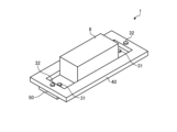
次に、図3A、図3Bを参照して第1の実施形態に係る液体吐出装置の構成について説明する。図3Aは、第1の実施形態に係る液体吐出装置の要部の構成を示す斜視図である。図3Bは、図3Aに示す液体吐出装置を別方向から見た斜視図である。
[First embodiment]
<Configuration of liquid ejection head>
Next, the configuration of the liquid ejection device according to the first embodiment will be described with reference to FIGS. 3A and 3B. FIG. 3A is a perspective view showing the configuration of main parts of the liquid ejection device according to the first embodiment. FIG. 3B is a perspective view of the liquid ejection device shown in FIG. 3A viewed from another direction.
液体吐出装置1は、ヘッド8と、第1固定部材31と、第2固定部材32と、フレーム40と、キャップ50とを有する。ヘッド8は、液体を吐出する第1面23aを有している。ヘッド8には、第1固定部材31を用いてキャップ50が取り付けられている。また、ヘッド8は、第2固定部材32を用いてフレーム40に固定されている。
The
フレーム40の材料は、たとえば、ステンレス鋼またはアルミニウムである。フレーム40は、ヘッド8を保持する保持部である。フレーム40は、図1、図2に示すフレーム7の一部であってもよく、フレーム7に固定される部材であってもよい。
The material of the
キャップ50は、第1固定部材31を用いてヘッド8に固定される。キャップ50は、第1面23aを保護する。第1面23aは、液体が吐出する吐出孔を有する吐出面である。キャップ50の材料は、たとえば金属製または樹脂製であってもよい。金属製の場合、キャップ50の材料は、たとえば、ステンレス鋼またはアルミニウム製であってもよい。また、樹脂製の場合、キャップ50の材料は、たとえば第1面23aから吐出される液体に対する耐性を有する熱可塑性樹脂または熱硬化性樹脂であってもよい。
The
第1固定部材31および第2固定部材32は、たとえば、ねじ部材である。図3に示す第1固定部材31および第2固定部材32は、ヘッド8の厚み方向に沿ってともに同じ側に向かって設けられている。具体的には、ヘッド8をフレーム40の上方から固定する場合であって、第1固定部材31はフレーム40からキャップ50の側(上方から下方)に向かって設けられ、第2固定部材32も同様の向きでヘッド8からフレーム40の側(上方から下方)に向かって設けられている。この構成によれば、第1固定部材31および第2固定部材32が重力の向きに取り付けられることとなり、液体吐出装置1の組み立てが容易になることから、組立時の作業性を向上させることができる。
The first fixing
また、第1固定部材31は、取り外し可能に設けられている。このため、キャップ50は、第1固定部材31を取り外すことによりヘッド8から取り外すことができる。
Further, the first fixing
図4は、第1の実施形態に係る液体吐出装置からキャップが取り外された状態を示す斜視図である。図4に示すように、第1固定部材31は、ヘッド8を貫通する孔21およびキャップ50に設けられた孔51に取り外し可能に設けられている。第1固定部材31は、キャップ50から離れる方向に取り外すことができる。このように第1固定部材31を取り外すことにより、液体吐出装置1は、ヘッド8をフレーム40に固定した状態でキャップ50を取り外すことができる。このため、作業性を向上させることができるとともに、使用時までキャップ50で第1面23aを保護して組立における信頼性を向上させることができる。
FIG. 4 is a perspective view showing a state in which the cap is removed from the liquid ejection device according to the first embodiment. As shown in FIG. 4, the first fixing
図5は、第1の実施形態の変形例1に係る液体吐出装置からキャップが取り外された状態を示す斜視図である。図5に示すように、第1固定部材31および第2固定部材32は、ヘッド8の厚み方向に沿って互いに反対側に向かって設けられている。第1固定部材31は、ヘッド8に設けられた孔21およびキャップ50を貫通する孔51に取り外し可能に設けられている。かかる液体吐出装置1においても、第1固定部材31を取り外すことにより、液体吐出装置1は、ヘッド8をフレーム40に固定した状態でヘッド8からキャップ50を取り外すことができる。具体的には、ヘッド8をフレーム40の下方から固定する場合であって、第1固定部材31はフレーム40からキャップ50の側(上方から下方)に向かって設けられ、第2固定部材32は第1固定部材31とは反対の向きでヘッド8からフレーム40の側(下方から上方)に向かって設けられている。この構成によっても、質量の大きい物から質量の小さい物へと第1固定部材31および第2固定部材32を挿通させることとなり、作業性を向上させることができるとともに、使用時までキャップ50で第1面23aを保護して組立における信頼性を向上させることができる。
FIG. 5 is a perspective view showing a state in which the cap is removed from the liquid ejection device according to
また、本変形例に係る液体吐出装置1では、第1固定部材31は、第1面23aから離れる方向であって、キャップ50と同じ方向に取り外すことができる。このため、第1固定部材31を取り外すための経路を、キャップ50を取り外す経路とは別に確保する必要がないため、たとえば、設計の自由度が高まる。
Furthermore, in the
図6は、第1の実施形態の変形例2に係る液体吐出装置の一例を示す斜視図である。図7は、図6に示す液体吐出装置からキャップが取り外された状態を示す斜視図である。
FIG. 6 is a perspective view showing an example of a liquid ejecting device according to
本変形例に係る液体吐出装置1は、フレーム40に代えて、筐体40Aを有している。筐体40Aは、ヘッド8を保持する保持部である。筐体40Aは、ヘッド8の一部を収容する空間を内部に有している。筐体40Aは、たとえば、内部空間と外部空間とを遮断する構造体であってもよい。かかる液体吐出装置1は、例えば揮発性を有する液体を吐出する塗装用途等に適用される。
The
図6に示すように、筐体40Aは、第2固定部材32を用いてヘッド8を固定する孔42を有している。また、キャップ50は、孔42に対応する位置に貫通部52を有している。貫通部52は、ヘッド8の厚み方向にキャップ50を貫通する貫通孔である。貫通部52は、キャップ50を固定するためではなく、第2固定部材32を挿通させてヘッド8を筐体40Aに固定するために使用される。貫通部52は、たとえば、キャップ50の端部に位置し、ヘッド8の厚み方向にキャップ50を貫通する形状、すなわち切欠きであってもよい。
As shown in FIG. 6, the
図7は、図6に示す液体吐出装置からキャップが取り外された状態を示す斜視図である。キャップ50は、第1面23aの長手方向の外側に位置する第1固定部材31を取り外すことによりヘッド8から取り外すことができる。また、ヘッド8は、第1面23aの短手方向の外側に位置する貫通部26を有している。貫通部26は、第2固定部材32を用いてヘッド8を筐体40Aに固定するために用いられる。
FIG. 7 is a perspective view showing the liquid ejecting device shown in FIG. 6 with the cap removed. The
ここで、第2固定部材32が位置する貫通部26およびその近傍の形状の一例について説明する。図8は、第2固定部材の近傍を示す平面図である。図9は、第2固定部材の近傍を示す断面図である。なお、図8では、キャップ50の図示を省略している。
Here, an example of the shape of the penetrating
ヘッド8は、図9に示すように、ノズルプレート23と、流路部材24と、ベースプレート25とを備える。ノズルプレート23は、液体を吐出する第1面23a、および第1面23aに対向する第2面23bを有する。流路部材24は、第2面23b上に位置し、ヘッド8の厚み方向に積層した複数のリザーバプレートを有する。ベースプレート25は、流路部材24を挟んでノズルプレート23とは反対側に位置している。ベースプレート25は、流路部材24が有する各リザーバプレートよりも厚みが大きい部材である。たとえば、ベースプレート25は、剛性および強度の高い金属の切削部品や樹脂成型品であってよい。
The
また、流路部材24は、厚み方向に貫通する貫通部26を有している。図8に示すように、貫通部26は、流路部材24の端面27に面する切欠き形状を有している。貫通部26は、一点鎖線で示す第2固定部材32から離れて位置しており、第2固定部材32は、ベースプレート25と筐体40Aとを締結することにより、ヘッド8を筐体40Aに固定する。なお、貫通部26が第2固定部材32から離れて位置しているとは、貫通部26の内壁が第2固定部材32と接触していないことを意味する。
Further, the
貫通部26は、第2固定部材32から離れて位置するため、流路部材24は、第2固定部材32の装着に伴うせん断応力を受けない。流路部材24を構成する各リザーバプレートは、ベースプレート25と比較して薄いため、第2固定部材32の締結に伴い応力を受けると、たとえば変形により吐出性能に不具合が生じる可能性がある。一方、本変形例に係るヘッド8によれば、第2固定部材32の装着に伴うせん断応力は、ベースプレート25が受けることになる。ベースプレート25は、流路部材24が有する各リザーバプレートよりも厚みが大きいことから、第2固定部材32の装着に伴い変形しにくい。このため、かかる貫通部26を有する流路部材24を備える液体吐出装置1によれば、たとえば、ヘッド8の耐久性が高まる。なお、必要以上にヘッド8を大きくしなくてもよく、ヘッド8の小型化にも寄与することができる。
Since the penetrating
次に、第1固定部材31が位置するキャップ50およびその近傍の形状の一例について説明する。図10は、第1固定部材の近傍を示す断面図である。
Next, an example of the shape of the
図10に示すように、キャップ50は、孔51を有している。また、ベースプレート25は、孔51に対応する位置に孔21を有している。第1固定部材31は、たとえば、孔21,51の内部に位置することにより、ベースプレート25とキャップ50とを取り外し可能に固定する。なお、図10では、第1固定部材31は、ベースプレート25側から設けられる例について示したが、孔21,51の形状を変更し、キャップ50側から設けられることとしてもよい。
As shown in FIG. 10, the
[第2の実施形態]
図11は、第2の実施形態に係る液体吐出装置の要部の構成を示す図である。図11に示す液体吐出装置1Aは、制御部140により制御可能なロボットアーム100を備える。ロボットアーム100の先端には、保持部101が位置している。
[Second embodiment]
FIG. 11 is a diagram showing the configuration of main parts of a liquid ejection device according to the second embodiment. The
液体吐出装置1Aは、保持部101が下方を向くようにロボットアーム100を位置させて、この保持部101に保持されるヘッド8を、ヘッド8の下側から上方に向かう第2固定部材32を用いて保持部101に固定してもよい。このようにロボットアーム100を位置させてヘッド8を固定することにより、ロボットアーム100を備えた液体吐出装置1Aにおいても、使用時までヘッド8の第1面23aをキャップ50で保護して組立における信頼性を向上させることができる。
The
図12は、第2の実施形態の変形例に係る液体吐出装置の要部の構成を示す図である。図12に示す液体吐出装置1Aは、制御部140により保持部101が上方を向くようにロボットアーム100を位置させて、この保持部101に保持されたヘッド8を、ヘッド8の上側から下方に向かう第2固定部材32を用いて保持部101に固定してもよい。このようにロボットアーム100を位置させてヘッド8を固定することにより、たとえばヘッド8や第2固定部材32に質量に伴う負荷が保持部101に伝わりやすくなり、たとえば、作業性が向上する。
FIG. 12 is a diagram showing the configuration of main parts of a liquid ejection device according to a modification of the second embodiment. In the
[液体吐出装置の組み立て方法]
図13は、第1の実施形態に係る液体吐出装置の組み立て方法の一例を示す図である。まず、取り外し可能な第1固定部材31を用いて、ヘッド8の第1面23aを覆うキャップ50を取り付ける(ステップS11)。第1固定部材31は、ヘッド8の厚み方向に沿って設けられる。第1固定部材31は、図示したようにヘッド8の上方から下方に向かって設けられてもよく、キャップ50の下方から上方に向かって設けられてもよい。
[Assembling method of liquid ejection device]
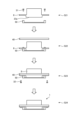
FIG. 13 is a diagram illustrating an example of a method for assembling the liquid ejection device according to the first embodiment. First, the
次に、キャップ50を取り付けたヘッド8の下方にフレーム40を位置させて(ステップS12)、第2固定部材32を用いてヘッド8とフレーム40とを固定する(ステップS13)。第2固定部材32は、図示したようにヘッド8の上方から下方に向かって設けられてもよく、キャップ50の下方から上方に向かって設けられてもよい。これにより、取り外し可能なキャップ50が装着された液体吐出装置1が完成する(ステップS14)。
Next, the
図14は、第1の実施形態の変形例に係る液体吐出装置の組み立て方法の一例を示す図である。まず、取り外し可能な第1固定部材31を用いて、ヘッド8の第1面23aを覆うキャップ50を取り付ける(ステップS21)。かかるステップS21は、上記したステップS11と同様である。
FIG. 14 is a diagram illustrating an example of a method for assembling a liquid ejection device according to a modification of the first embodiment. First, the
次に、キャップ50を取り付けたヘッド8の上方にフレーム40を位置させて(ステップS22)、第2固定部材32を用いてヘッド8とフレーム40とを固定する(ステップS23)。第2固定部材32は、図示したようにキャップ50の下方から上方に向かって設けられてもよく、ヘッド8の上方から下方に向かって設けられてもよい。これにより、取り外し可能なキャップ50が装着された液体吐出装置1が完成する(ステップS24)。
Next, the
以上、本開示の各実施形態について説明したが、本開示は上記実施形態に限定されるものではなく、その趣旨を逸脱しない限りにおいて種々の変更が可能である。たとえば、図11および/または図12に示すロボットアーム100の先端に位置する保持部101として、フレーム40または筐体40Aを位置させてもよい。
Although each embodiment of the present disclosure has been described above, the present disclosure is not limited to the above embodiments, and various changes can be made without departing from the spirit thereof. For example, the
以上のように、実施形態に係る液体吐出装置1は、ヘッド8と、保持部と、キャップ50と、第2固定部材32とを備える。ヘッド8は、液体を吐出する第1面23aを有する。保持部は、ヘッド8を保持する。キャップ50は、取り外し可能な第1固定部材31を用いてヘッド8に固定され、第1面23aを覆う。第2固定部材32は、ヘッド8と保持部とを固定する。これにより、ヘッド8の使用時まで第1面23aをキャップ50で保護して液体吐出装置1の組立における信頼性を向上させることができる。
As described above, the
また、実施形態に係る第1固定部材31および第2固定部材32は、ヘッド8の厚み方向に沿ってともに同じ側に向かって設けられている。これにより、作業性を向上させることができるとともに、ヘッド8の使用時まで第1面23aをキャップ50で保護して液体吐出装置1の組立における信頼性を向上させることができる。
Further, the first fixing
また、実施形態に係る第1固定部材31および第2固定部材32は、ヘッド8の厚み方向に沿って互いに反対側に向かって設けられている。これにより、作業性を向上させることができるとともに、ヘッド8の使用時まで第1面23aをキャップ50で保護して液体吐出装置1の組立における信頼性を向上させることができる。
Further, the first fixing
また、実施形態に係る第1固定部材31は、保持部からキャップ50が位置する方向に取り外し可能に設けられている。これにより、作業性を向上させることができるとともに、ヘッド8の使用時まで第1面23aをキャップ50で保護して液体吐出装置1の組立における信頼性を向上させることができる。
Further, the first fixing
また、実施形態に係る液体吐出装置1Aは、先端に保持部101が位置するロボットアーム100を備える。これにより、ロボットアーム100を備えた液体吐出装置1Aにおいても、ヘッド8の使用時までヘッド8の第1面23aをキャップ50で保護して液体吐出装置1の組立における信頼性を向上させることができる。
Further, the
また、実施形態に係るヘッド8は、第1面23aおよび第1面23aに対向する第2面23bを有するノズルプレート23と、第2面23b上に位置し、ヘッド8の厚み方向に積層した複数のリザーバプレートを有する流路部材24と、流路部材24を挟んでノズルプレート23とは反対側に位置し、各リザーバプレートよりも厚みが大きいベースプレート25とを備える。ベースプレート25は、第1固定部材31を取り付ける第1孔と、第2固定部材32を取り付ける第2孔とを有する。これにより、ヘッド8の耐久性が高まる。
Further, the
また、実施形態に係る流路部材24は、第2孔に対応する位置に第2固定部材32から離れて位置する第1貫通部を有する。これにより、ヘッド8の耐久性が高まるとともに、ヘッド8の小型化にも寄与することができる。
Further, the
また、実施形態に係るキャップ50は、第2孔に対応する位置に第2固定部材32から離れて位置する第2貫通部を有する。これにより、作業性を向上させることができる。
Further, the
さらなる効果や変形例は、当業者によって容易に導き出すことができる。このため、本開示のより広範な態様は、以上のように表しかつ記述した特定の詳細および代表的な実施形態に限定されるものではない。したがって、添付の請求の範囲およびその均等物によって定義される総括的な発明の概念の精神または範囲から逸脱することなく、様々な変更が可能である。 Further advantages and modifications can be easily deduced by those skilled in the art. Therefore, the broader aspects of this disclosure are not limited to the specific details and representative embodiments shown and described above. Accordingly, various changes may be made without departing from the spirit or scope of the general inventive concept as defined by the appended claims and their equivalents.
1,1A 液体吐出装置
4 塗布機
6 搬送ローラ(搬送部の一例)
8 ヘッド
10 乾燥機
14 制御部
23 ノズルプレート
23a 第1面
24 流路部材
25 ベースプレート
31 第1固定部材
32 第2固定部材
40 フレーム
50 キャップ
1,1A
8
Claims (17)
前記ヘッドを保持する保持部と、
前記第1面を覆うキャップを取り外し可能に固定する第1固定部材と、
前記ヘッドと前記保持部とを固定する第2固定部材と
を備え、
前記第1固定部材および前記第2固定部材は、前記ヘッドの厚み方向に沿って互いに反対側に向かって設けられている
液体吐出装置。 a head having a first surface that discharges liquid;
a holding part that holds the head;
a first fixing member that removably fixes a cap covering the first surface;
a second fixing member that fixes the head and the holding part ;
The first fixing member and the second fixing member are provided facing oppositely to each other along the thickness direction of the head.
Liquid discharge device.
前記ヘッドを保持する保持部と、
前記第1面を覆うキャップを取り外し可能に固定する第1固定部材と、
前記ヘッドと前記保持部とを固定する第2固定部材と
を備え、
前記第1固定部材は、前記保持部から前記第1面が位置する方向に取り外し可能に設けられている
液体吐出装置。 a head having a first surface that discharges liquid;
a holding part that holds the head;
a first fixing member that removably fixes a cap covering the first surface;
a second fixing member that fixes the head and the holding part;
Equipped with
The first fixing member is provided so as to be removable from the holding portion in the direction in which the first surface is located.
Liquid discharge device.
請求項2に記載の液体吐出装置。 The liquid ejecting device according to claim 2 , wherein the first fixing member and the second fixing member are both provided toward the same side along the thickness direction of the head.
請求項1~3のいずれか1つに記載の液体吐出装置。 The liquid ejecting device according to any one of claims 1 to 3 , further comprising a robot arm with the holding portion located at the tip thereof.
前記ヘッドを保持する保持部と、
前記第1面を覆うキャップを取り外し可能に固定する第1固定部材と、
前記ヘッドと前記保持部とを固定する第2固定部材と
を備え、
前記ヘッドは、
前記第1面および前記第1面に対向する第2面を有するノズルプレートと、
前記第2面上に位置し、前記ヘッドの厚み方向に積層した複数のリザーバプレートを有する流路部材と、
前記流路部材を挟んで前記ノズルプレートとは反対側に位置し、各リザーバプレートよりも厚みが大きいベースプレートと
を備え、
前記ベースプレートは、前記第1固定部材を取り付ける第1孔と、前記第2固定部材を取り付ける第2孔とを有する
液体吐出装置。 a head having a first surface for discharging liquid;
a holding part that holds the head;
a first fixing member that removably fixes a cap covering the first surface;
a second fixing member that fixes the head and the holding part;
Equipped with
The head is
a nozzle plate having the first surface and a second surface opposite to the first surface;
a flow path member located on the second surface and having a plurality of reservoir plates stacked in the thickness direction of the head;
a base plate located on the opposite side of the nozzle plate across the flow path member and having a thickness greater than each reservoir plate;
The base plate has a first hole for attaching the first fixing member and a second hole for attaching the second fixing member.
Liquid discharge device.
請求項5に記載の液体吐出装置。 The liquid ejecting device according to claim 5 , wherein the flow path member has a first through portion located apart from the second fixing member at a position corresponding to the second hole.
前記キャップは、前記第2孔に対応する位置に前記第2固定部材から離れて位置する第2貫通部を有する
請求項6に記載の液体吐出装置。 further comprising the cap fixed to the head and covering the first surface,
The liquid ejecting device according to claim 6 , wherein the cap has a second penetrating portion located apart from the second fixing member at a position corresponding to the second hole.
前記キャップを取り付けた前記ヘッドを保持部に固定する工程と、
前記保持部に固定された前記ヘッドからキャップを取り外す工程と
を含む液体吐出装置の組み立て方法。 Attaching a cap that covers the first surface to a head having a first surface that discharges liquid;
fixing the head with the cap attached to a holding part;
A method for assembling a liquid ejecting device, comprising: removing a cap from the head fixed to the holding part.
前記ヘッドは、第2固定部材を用いて前記保持部に固定され、
前記第1固定部材および前記第2固定部材は、前記ヘッドの厚み方向に沿ってともに同じ側に向かって設けられている
請求項8に記載の液体吐出装置の組み立て方法。 the cap is fixed to the head using a removable first fixing member;
The head is fixed to the holding part using a second fixing member,
The method for assembling a liquid ejecting device according to claim 8 , wherein the first fixing member and the second fixing member are both provided toward the same side along the thickness direction of the head.
前記ヘッドは、第2固定部材を用いて前記保持部に固定され、
前記第1固定部材および前記第2固定部材は、前記ヘッドの厚み方向に沿って互いに反対側に向かって設けられている
請求項8に記載の液体吐出装置の組み立て方法。 the cap is fixed to the head using a removable first fixing member;
The head is fixed to the holding part using a second fixing member,
The method for assembling a liquid ejection device according to claim 8 , wherein the first fixing member and the second fixing member are provided facing oppositely to each other along the thickness direction of the head.
請求項9または10に記載の液体吐出装置の組み立て方法。 The method for assembling a liquid ejecting device according to claim 9 or 10 , further comprising the step of removably fixing the first fixing member in a direction in which the cap separates from the first surface.
請求項8~11のいずれか1つに記載の液体吐出装置の組み立て方法。 The method for assembling a liquid ejecting device according to any one of claims 8 to 11 , wherein the liquid ejecting device is a device equipped with a robot arm, and the holding portion is located at the tip of the robot arm.
前記保持部の下方に位置する前記ヘッドを、前記ヘッド側から上方に向かう第2固定部材を用いて前記保持部に固定する工程と
を含む請求項12に記載の液体吐出装置の組み立て方法。 positioning the robot arm so that the holding part faces downward;
13. The method of assembling a liquid ejecting device according to claim 12 , further comprising the step of fixing the head located below the holding part to the holding part using a second fixing member directed upward from the head side.
前記保持部の上方に位置する前記ヘッドを、前記ヘッド側から下方に向かう第2固定部材を用いて前記保持部に固定する工程と
を含む請求項12に記載の液体吐出装置の組み立て方法。 positioning the robot arm so that the holding part faces upward;
13. The method for assembling a liquid ejecting device according to claim 12 , further comprising the step of fixing the head located above the holding part to the holding part using a second fixing member directed downward from the head side.
前記第1面および前記第1面に対向する第2面を有するノズルプレートと、
前記第2面上に位置し、前記ヘッドの厚み方向に積層した複数のリザーバプレートを有する流路部材と、
前記流路部材を挟んで前記ノズルプレートとは反対側に位置し、各リザーバプレートよりも厚みが大きいベースプレートと
を備え、
前記ベースプレートは、前記第1固定部材を用いて前記キャップを取り外し可能に前記ヘッドに取り付ける第1孔と、前記第2固定部材を用いて前記ヘッドを前記保持部に固定する第2孔とを有する
請求項9~11のいずれか1つに記載の液体吐出装置の組み立て方法。 The head is
a nozzle plate having the first surface and a second surface opposite to the first surface;
a flow path member located on the second surface and having a plurality of reservoir plates stacked in the thickness direction of the head;
a base plate located on the opposite side of the nozzle plate across the flow path member and having a thickness greater than each reservoir plate;
The base plate has a first hole that removably attaches the cap to the head using the first fixing member, and a second hole that fixes the head to the holding part using the second fixing member. A method for assembling a liquid ejection device according to any one of claims 9 to 11 .
請求項15に記載の液体吐出装置の組み立て方法。 The method for assembling a liquid ejecting device according to claim 15 , wherein the flow path member has a first through portion located apart from the second fixing member at a position corresponding to the second hole.
請求項16に記載の液体吐出装置の組み立て方法。 17. The method for assembling a liquid ejecting device according to claim 16 , wherein the cap has a second penetrating portion located away from the second fixing member at a position corresponding to the second hole.
Priority Applications (1)
| Application Number | Priority Date | Filing Date | Title |
|---|---|---|---|
| JP2024028116A JP2024054406A (en) | 2021-03-31 | 2024-02-28 | LIQUID DISCHARGE APPARATUS AND METHOD FOR ASSEMBLING LIQUID DISCHARGE APPARATUS - Patent application |
Applications Claiming Priority (3)
| Application Number | Priority Date | Filing Date | Title |
|---|---|---|---|
| JP2021061817 | 2021-03-31 | ||
| JP2021061817 | 2021-03-31 | ||
| PCT/JP2022/013711 WO2022210211A1 (en) | 2021-03-31 | 2022-03-23 | Liquid discharge device and assembly method for liquid discharge device |
Related Child Applications (1)
| Application Number | Title | Priority Date | Filing Date |
|---|---|---|---|
| JP2024028116A Division JP2024054406A (en) | 2021-03-31 | 2024-02-28 | LIQUID DISCHARGE APPARATUS AND METHOD FOR ASSEMBLING LIQUID DISCHARGE APPARATUS - Patent application |
Publications (3)
| Publication Number | Publication Date |
|---|---|
| JPWO2022210211A1 JPWO2022210211A1 (en) | 2022-10-06 |
| JPWO2022210211A5 JPWO2022210211A5 (en) | 2024-01-10 |
| JP7447355B2 true JP7447355B2 (en) | 2024-03-11 |
Family
ID=83456668
Family Applications (2)
| Application Number | Title | Priority Date | Filing Date |
|---|---|---|---|
| JP2023511088A Active JP7447355B2 (en) | 2021-03-31 | 2022-03-23 | Liquid ejection device and method of assembling the liquid ejection device |
| JP2024028116A Pending JP2024054406A (en) | 2021-03-31 | 2024-02-28 | LIQUID DISCHARGE APPARATUS AND METHOD FOR ASSEMBLING LIQUID DISCHARGE APPARATUS - Patent application |
Family Applications After (1)
| Application Number | Title | Priority Date | Filing Date |
|---|---|---|---|
| JP2024028116A Pending JP2024054406A (en) | 2021-03-31 | 2024-02-28 | LIQUID DISCHARGE APPARATUS AND METHOD FOR ASSEMBLING LIQUID DISCHARGE APPARATUS - Patent application |
Country Status (4)
| Country | Link |
|---|---|
| EP (1) | EP4316851A1 (en) |
| JP (2) | JP7447355B2 (en) |
| CN (1) | CN117083180A (en) |
| WO (1) | WO2022210211A1 (en) |
Citations (5)
| Publication number | Priority date | Publication date | Assignee | Title |
|---|---|---|---|---|
| JP2002321387A (en) | 2001-02-23 | 2002-11-05 | Canon Inc | Storage form of ink jet head and method for liquid filling during storage of ink jet head |
| JP2005212209A (en) | 2004-01-28 | 2005-08-11 | Konica Minolta Holdings Inc | Head cap and head cover |
| JP2008229932A (en) | 2007-03-19 | 2008-10-02 | Brother Ind Ltd | Liquid discharging apparatus, and head assembly |
| JP2016175358A (en) | 2015-03-23 | 2016-10-06 | 株式会社ミマキエンジニアリング | Ink jet printer |
| JP2019098593A (en) | 2017-11-30 | 2019-06-24 | 株式会社リコー | Liquid discharge head protection member, liquid discharge head, and liquid discharge unit |
Family Cites Families (2)
| Publication number | Priority date | Publication date | Assignee | Title |
|---|---|---|---|---|
| JP4241792B2 (en) | 2006-09-25 | 2009-03-18 | ブラザー工業株式会社 | Cap and inkjet protection assembly |
| JP2009184210A (en) | 2008-02-06 | 2009-08-20 | Brother Ind Ltd | Head assembly and liquid delivering apparatus containing this |
-
2022
- 2022-03-23 EP EP22780425.9A patent/EP4316851A1/en active Pending
- 2022-03-23 CN CN202280025199.6A patent/CN117083180A/en active Pending
- 2022-03-23 WO PCT/JP2022/013711 patent/WO2022210211A1/en active Application Filing
- 2022-03-23 JP JP2023511088A patent/JP7447355B2/en active Active
-
2024
- 2024-02-28 JP JP2024028116A patent/JP2024054406A/en active Pending
Patent Citations (5)
| Publication number | Priority date | Publication date | Assignee | Title |
|---|---|---|---|---|
| JP2002321387A (en) | 2001-02-23 | 2002-11-05 | Canon Inc | Storage form of ink jet head and method for liquid filling during storage of ink jet head |
| JP2005212209A (en) | 2004-01-28 | 2005-08-11 | Konica Minolta Holdings Inc | Head cap and head cover |
| JP2008229932A (en) | 2007-03-19 | 2008-10-02 | Brother Ind Ltd | Liquid discharging apparatus, and head assembly |
| JP2016175358A (en) | 2015-03-23 | 2016-10-06 | 株式会社ミマキエンジニアリング | Ink jet printer |
| JP2019098593A (en) | 2017-11-30 | 2019-06-24 | 株式会社リコー | Liquid discharge head protection member, liquid discharge head, and liquid discharge unit |
Also Published As
| Publication number | Publication date |
|---|---|
| EP4316851A1 (en) | 2024-02-07 |
| WO2022210211A1 (en) | 2022-10-06 |
| JPWO2022210211A1 (en) | 2022-10-06 |
| JP2024054406A (en) | 2024-04-16 |
| CN117083180A (en) | 2023-11-17 |
Similar Documents
| Publication | Publication Date | Title |
|---|---|---|
| US8550585B2 (en) | Liquid ejecting apparatus | |
| US6742864B2 (en) | Waste ink removal system | |
| JP7447355B2 (en) | Liquid ejection device and method of assembling the liquid ejection device | |
| JP6954058B2 (en) | Liquid discharge head protection member, liquid discharge head and liquid discharge unit | |
| JP2009214510A (en) | Liquid jet head and liquid jet apparatus | |
| JP7328105B2 (en) | Liquid ejection head and recording device | |
| WO2020250873A1 (en) | Liquid dispensing head and recording device | |
| WO2022210915A1 (en) | Liquid discharge head, discharge head structure, and recording device | |
| JP5148555B2 (en) | Inkjet head | |
| JP4513821B2 (en) | Liquid ejection device | |
| WO2024048749A1 (en) | Liquid ejection head and liquid ejection device | |
| JP2023128813A (en) | Liquid discharge head and recording device | |
| WO2023190923A1 (en) | Liquid ejection head and recording device | |
| JP2003011378A (en) | Ink-jet recording apparatus and wiping method in the recording apparatus | |
| JP2004106433A (en) | Inkjet recorder | |
| JP2019177638A (en) | Liquid discharge head and recording device using the same | |
| CN114423615B (en) | Liquid ejection head and recording apparatus | |
| WO2023176700A1 (en) | Liquid discharge head and recording device | |
| WO2023190353A1 (en) | Liquid dispensing head and recording device | |
| WO2024024964A1 (en) | Liquid supply member, liquid discharge head, and recording device | |
| JP7293337B2 (en) | Liquid ejection head and recording device | |
| JP7288073B2 (en) | Droplet ejection head and recording device | |
| WO2021085632A1 (en) | Liquid discharge head and recording device | |
| EP2741917B1 (en) | Apparatus and method for disposing inkjet cartridges in a carrier | |
| WO2020203907A1 (en) | Liquid ejecting head and recording device |
Legal Events
| Date | Code | Title | Description |
|---|---|---|---|
| A521 | Request for written amendment filed |
Free format text: JAPANESE INTERMEDIATE CODE: A523 Effective date: 20230926 |
|
| A621 | Written request for application examination |
Free format text: JAPANESE INTERMEDIATE CODE: A621 Effective date: 20230926 |
|
| A521 | Request for written amendment filed |
Free format text: JAPANESE INTERMEDIATE CODE: A523 Effective date: 20231225 |
|
| A871 | Explanation of circumstances concerning accelerated examination |
Free format text: JAPANESE INTERMEDIATE CODE: A871 Effective date: 20231225 |
|
| TRDD | Decision of grant or rejection written | ||
| A01 | Written decision to grant a patent or to grant a registration (utility model) |
Free format text: JAPANESE INTERMEDIATE CODE: A01 Effective date: 20240130 |
|
| A61 | First payment of annual fees (during grant procedure) |
Free format text: JAPANESE INTERMEDIATE CODE: A61 Effective date: 20240228 |
|
| R150 | Certificate of patent or registration of utility model |
Ref document number: 7447355 Country of ref document: JP Free format text: JAPANESE INTERMEDIATE CODE: R150 |