JP7447313B2 - Imaging module structure - Google Patents
Imaging module structure Download PDFInfo
- Publication number
- JP7447313B2 JP7447313B2 JP2022567450A JP2022567450A JP7447313B2 JP 7447313 B2 JP7447313 B2 JP 7447313B2 JP 2022567450 A JP2022567450 A JP 2022567450A JP 2022567450 A JP2022567450 A JP 2022567450A JP 7447313 B2 JP7447313 B2 JP 7447313B2
- Authority
- JP
- Japan
- Prior art keywords
- lens
- imaging module
- module structure
- circlip
- present
- Prior art date
- Legal status (The legal status is an assumption and is not a legal conclusion. Google has not performed a legal analysis and makes no representation as to the accuracy of the status listed.)
- Active
Links
- 238000003384 imaging method Methods 0.000 title claims description 33
- 230000002093 peripheral effect Effects 0.000 claims description 7
- 229910000975 Carbon steel Inorganic materials 0.000 claims description 3
- 229910000639 Spring steel Inorganic materials 0.000 claims description 3
- 239000010962 carbon steel Substances 0.000 claims description 3
- 239000000853 adhesive Substances 0.000 description 9
- 230000001070 adhesive effect Effects 0.000 description 9
- 238000010586 diagram Methods 0.000 description 7
- 238000009434 installation Methods 0.000 description 5
- 238000000034 method Methods 0.000 description 5
- 238000006073 displacement reaction Methods 0.000 description 4
- 230000003287 optical effect Effects 0.000 description 3
- 238000007796 conventional method Methods 0.000 description 2
- 230000000694 effects Effects 0.000 description 2
- 230000005484 gravity Effects 0.000 description 2
- 230000017525 heat dissipation Effects 0.000 description 2
- 230000000670 limiting effect Effects 0.000 description 2
- 230000004048 modification Effects 0.000 description 2
- 238000012986 modification Methods 0.000 description 2
- 229910000831 Steel Inorganic materials 0.000 description 1
- XAGFODPZIPBFFR-UHFFFAOYSA-N aluminium Chemical compound [Al] XAGFODPZIPBFFR-UHFFFAOYSA-N 0.000 description 1
- 229910052782 aluminium Inorganic materials 0.000 description 1
- 238000005452 bending Methods 0.000 description 1
- 239000000919 ceramic Substances 0.000 description 1
- 238000005260 corrosion Methods 0.000 description 1
- 230000007797 corrosion Effects 0.000 description 1
- 238000001514 detection method Methods 0.000 description 1
- 239000013013 elastic material Substances 0.000 description 1
- 238000005516 engineering process Methods 0.000 description 1
- 239000000463 material Substances 0.000 description 1
- 230000002265 prevention Effects 0.000 description 1
- 239000010959 steel Substances 0.000 description 1
- 239000000758 substrate Substances 0.000 description 1
- 238000004381 surface treatment Methods 0.000 description 1
- 238000010301 surface-oxidation reaction Methods 0.000 description 1
Images


Classifications
-
- G—PHYSICS
- G03—PHOTOGRAPHY; CINEMATOGRAPHY; ANALOGOUS TECHNIQUES USING WAVES OTHER THAN OPTICAL WAVES; ELECTROGRAPHY; HOLOGRAPHY
- G03B—APPARATUS OR ARRANGEMENTS FOR TAKING PHOTOGRAPHS OR FOR PROJECTING OR VIEWING THEM; APPARATUS OR ARRANGEMENTS EMPLOYING ANALOGOUS TECHNIQUES USING WAVES OTHER THAN OPTICAL WAVES; ACCESSORIES THEREFOR
- G03B17/00—Details of cameras or camera bodies; Accessories therefor
- G03B17/02—Bodies
-
- G—PHYSICS
- G03—PHOTOGRAPHY; CINEMATOGRAPHY; ANALOGOUS TECHNIQUES USING WAVES OTHER THAN OPTICAL WAVES; ELECTROGRAPHY; HOLOGRAPHY
- G03B—APPARATUS OR ARRANGEMENTS FOR TAKING PHOTOGRAPHS OR FOR PROJECTING OR VIEWING THEM; APPARATUS OR ARRANGEMENTS EMPLOYING ANALOGOUS TECHNIQUES USING WAVES OTHER THAN OPTICAL WAVES; ACCESSORIES THEREFOR
- G03B30/00—Camera modules comprising integrated lens units and imaging units, specially adapted for being embedded in other devices, e.g. mobile phones or vehicles
-
- H—ELECTRICITY
- H04—ELECTRIC COMMUNICATION TECHNIQUE
- H04N—PICTORIAL COMMUNICATION, e.g. TELEVISION
- H04N23/00—Cameras or camera modules comprising electronic image sensors; Control thereof
- H04N23/50—Constructional details
- H04N23/55—Optical parts specially adapted for electronic image sensors; Mounting thereof
-
- G—PHYSICS
- G02—OPTICS
- G02B—OPTICAL ELEMENTS, SYSTEMS OR APPARATUS
- G02B7/00—Mountings, adjusting means, or light-tight connections, for optical elements
- G02B7/02—Mountings, adjusting means, or light-tight connections, for optical elements for lenses
-
- G—PHYSICS
- G02—OPTICS
- G02B—OPTICAL ELEMENTS, SYSTEMS OR APPARATUS
- G02B7/00—Mountings, adjusting means, or light-tight connections, for optical elements
- G02B7/02—Mountings, adjusting means, or light-tight connections, for optical elements for lenses
- G02B7/026—Mountings, adjusting means, or light-tight connections, for optical elements for lenses using retaining rings or springs
-
- G—PHYSICS
- G03—PHOTOGRAPHY; CINEMATOGRAPHY; ANALOGOUS TECHNIQUES USING WAVES OTHER THAN OPTICAL WAVES; ELECTROGRAPHY; HOLOGRAPHY
- G03B—APPARATUS OR ARRANGEMENTS FOR TAKING PHOTOGRAPHS OR FOR PROJECTING OR VIEWING THEM; APPARATUS OR ARRANGEMENTS EMPLOYING ANALOGOUS TECHNIQUES USING WAVES OTHER THAN OPTICAL WAVES; ACCESSORIES THEREFOR
- G03B17/00—Details of cameras or camera bodies; Accessories therefor
- G03B17/55—Details of cameras or camera bodies; Accessories therefor with provision for heating or cooling, e.g. in aircraft
-
- G—PHYSICS
- G03—PHOTOGRAPHY; CINEMATOGRAPHY; ANALOGOUS TECHNIQUES USING WAVES OTHER THAN OPTICAL WAVES; ELECTROGRAPHY; HOLOGRAPHY
- G03B—APPARATUS OR ARRANGEMENTS FOR TAKING PHOTOGRAPHS OR FOR PROJECTING OR VIEWING THEM; APPARATUS OR ARRANGEMENTS EMPLOYING ANALOGOUS TECHNIQUES USING WAVES OTHER THAN OPTICAL WAVES; ACCESSORIES THEREFOR
- G03B17/00—Details of cameras or camera bodies; Accessories therefor
- G03B17/56—Accessories
- G03B17/563—Camera grips, handles
-
- H—ELECTRICITY
- H04—ELECTRIC COMMUNICATION TECHNIQUE
- H04N—PICTORIAL COMMUNICATION, e.g. TELEVISION
- H04N23/00—Cameras or camera modules comprising electronic image sensors; Control thereof
- H04N23/50—Constructional details
-
- H—ELECTRICITY
- H04—ELECTRIC COMMUNICATION TECHNIQUE
- H04N—PICTORIAL COMMUNICATION, e.g. TELEVISION
- H04N23/00—Cameras or camera modules comprising electronic image sensors; Control thereof
- H04N23/50—Constructional details
- H04N23/51—Housings
-
- H—ELECTRICITY
- H04—ELECTRIC COMMUNICATION TECHNIQUE
- H04N—PICTORIAL COMMUNICATION, e.g. TELEVISION
- H04N23/00—Cameras or camera modules comprising electronic image sensors; Control thereof
- H04N23/50—Constructional details
- H04N23/52—Elements optimising image sensor operation, e.g. for electromagnetic interference [EMI] protection or temperature control by heat transfer or cooling elements
Landscapes
- Physics & Mathematics (AREA)
- Engineering & Computer Science (AREA)
- General Physics & Mathematics (AREA)
- Multimedia (AREA)
- Signal Processing (AREA)
- Optics & Photonics (AREA)
- Aviation & Aerospace Engineering (AREA)
- Electromagnetism (AREA)
- Lens Barrels (AREA)
- Fittings On The Vehicle Exterior For Carrying Loads, And Devices For Holding Or Mounting Articles (AREA)
Description
本発明は光学技術分野に属し、特に車載撮像モジュール構造に関する。 TECHNICAL FIELD The present invention belongs to the field of optical technology, and particularly relates to the structure of a vehicle-mounted imaging module.
現在、自動車業界は自動運転方向に向かって進んでおり、自動車の設計者と開発者も自動車システムの能動的な安全を重視している。能動的な安全と自動運転を実現するために、先進運転支援システムは基礎であり、キーである。 Currently, the automotive industry is moving towards autonomous driving, and automotive designers and developers are also placing greater emphasis on active safety in vehicle systems. Advanced driver assistance systems are the foundation and key to realizing active safety and autonomous driving.
補助システムにおけるカメラの応用は非常に重要な地位を有し、前方視、後方視、側面視、360パノラマなどの撮像モジュールにより、自己適応ナビ制御、死角検出、衝突防止、駐車補助などの機能を実現することができる。これらの機能を実現するために、撮像モジュールと自動車との位置関係は非常に重要であり、撮像モジュール固定の良否は上記機能を実現する効果と成否を直接決定することになる。 The application of cameras in auxiliary systems has a very important position, with front view, rear view, side view, 360 panoramic and other imaging modules, providing functions such as self-adaptive navigation control, blind spot detection, collision prevention, parking assistance, etc. It can be realized. In order to realize these functions, the positional relationship between the imaging module and the vehicle is very important, and the quality of fixing the imaging module directly determines the effectiveness and success or failure of realizing the above functions.
従来の撮像の固定方式は主にネジ接続、締結具接続、接着剤接続などである。使用時間の増加に伴い、ネジ、締結具、接着剤の接続方式に緩み、振動脱落又は破断などのフェールリスクが存在する可能性がある。上記方式に必要な構造部材が多く、組み立て方式が複雑で、コストが高い。 Traditional imaging fixation methods mainly include screw connection, fastener connection, adhesive connection, etc. As usage time increases, there is a possibility that screws, fasteners, and adhesive connection methods may become loose, vibrate, fall off, or break, causing failure risks. The above method requires many structural members, the assembly method is complicated, and the cost is high.
本発明は、従来の撮像固定方式に緩み、振動する時の脱落などが発生しやすいという不具合を解決するために、撮像モジュール構造を提供することを目的とする。 SUMMARY OF THE INVENTION An object of the present invention is to provide an imaging module structure in order to solve the problem that conventional imaging fixing methods tend to loosen and fall off when vibrating.
上記目的を達成するために、本発明は、収容部を有する上筐体と、前記収容部に取り付けられるレンズと、を備える撮像モジュール構造を提供し、押圧部と係止部を備えるサークリップをさらに備え、前記上筐体に案内溝が設けられ、前記レンズの外周壁に係止溝が設けられ、前記係止部は前記案内溝に沿って前記レンズの係止溝内に係止される。 In order to achieve the above object, the present invention provides an imaging module structure including an upper housing having a housing part, a lens attached to the housing part, and a circlip having a pressing part and a locking part. Further, a guide groove is provided in the upper housing, a locking groove is provided in the outer peripheral wall of the lens, and the locking part is locked in the locking groove of the lens along the guide groove. .
本発明の一態様によれば、前記係止部は凸台構造を有し、前記係止部が前記係止溝に係止される時、前記凸台構造は前記係止溝内に位置する。 According to one aspect of the present invention, the locking part has a convex structure, and when the locking part is locked in the locking groove, the convex structure is located in the locking groove. .
本発明の一態様によれば、前記係止部の先端の側面は前記案内溝と係合する案内リブを有する。 According to one aspect of the present invention, a side surface of the tip of the locking portion has a guide rib that engages with the guide groove.
本発明の一態様によれば、前記押圧部と前記係止部との間に接続部がさらに設けられ、前記接続部の側辺に前記案内溝と係合する第2案内リブが設けられる。 According to one aspect of the present invention, a connecting portion is further provided between the pressing portion and the locking portion, and a second guide rib that engages with the guide groove is provided on a side of the connecting portion.
本発明の一態様によれば、前記接続部は直立板状であり、前記押圧部は前記接続部に垂直に接続され、水平押圧面を有する。 According to one aspect of the present invention, the connecting portion has an upright plate shape, and the pressing portion is connected perpendicularly to the connecting portion and has a horizontal pressing surface.
本発明の一態様によれば、前記上筐体にさらにストッパが設けられ、前記ストッパは前記案内溝の片側に位置し、前記押圧部と係合する。 According to one aspect of the present invention, a stopper is further provided on the upper casing, and the stopper is located on one side of the guide groove and engages with the pressing portion.
本発明の一態様によれば、前記案内溝は前記上筐体の底部に設けられる。 According to one aspect of the present invention, the guide groove is provided at the bottom of the upper housing.
本発明の一態様によれば、前記接続部に貫通孔が設けられる。 According to one aspect of the present invention, a through hole is provided in the connecting portion.
本発明の一態様によれば、前記サークリップは炭素鋼材又はバネ鋼材である。 According to one aspect of the invention, the circlip is made of carbon steel or spring steel.
本発明の一態様によれば、前記レンズと前記上筐体の収容部とは軸孔で係合される。 According to one aspect of the present invention, the lens and the housing portion of the upper housing are engaged with each other through a shaft hole.
本発明の一態様によれば、前記レンズの末端の周壁には、前記上筐体に係合する取付平面が設けられる。 According to one aspect of the invention, a peripheral wall at a distal end of the lens is provided with a mounting plane that engages with the upper housing.
本発明の一態様によれば、前記レンズは一体型レンズである。 According to one aspect of the invention, the lens is a monolithic lens.
本発明の一態様によれば、前記撮像モジュール構造は感光チップが設けられる配線板をさらに備え、前記レンズは、末端が前記配線板に固定して接続され、
前記配線板は、回路基板と、前記回路基板に密着する放熱板とを備える。
According to one aspect of the present invention, the imaging module structure further includes a wiring board provided with a photosensitive chip, and the lens has an end fixedly connected to the wiring board,
The wiring board includes a circuit board and a heat sink that is in close contact with the circuit board.
本発明の一態様によれば、前記撮像モジュール構造は前記上筐体に接続される下筐体をさらに備える。 According to one aspect of the present invention, the imaging module structure further includes a lower housing connected to the upper housing.
本発明の一態様によれば、本発明のサークリップは押圧部と係止部を備え、上筐体にさらに案内溝が設けられ、レンズの外周壁に係止溝が設けられる。そして、本発明のサークリップを案内溝内に配置することができ、サークリップの押圧部を押圧することにより、サークリップの係止部が最終的にレンズの係止溝内に係止されるため、撮像モジュールへのレンズの位置決めが実現される。従来技術における接着剤接続、ネジ接続などの方式に比べ、緩み、脱落、破断などの不具合が発生せず、レンズの撮影品質及び耐用年数を確保することに有利である。また、本発明はレンズを固定するためにサークリップを設けているので、接着剤接続、ネジ接続に比べ、組立操作がより簡便で迅速である。 According to one aspect of the present invention, the circlip of the present invention includes a pressing portion and a locking portion, a guide groove is further provided in the upper housing, and a locking groove is provided in the outer peripheral wall of the lens. The circlip of the present invention can be placed in the guide groove, and by pressing the pressing part of the circlip, the locking part of the circlip is finally locked in the locking groove of the lens. Therefore, positioning of the lens to the imaging module is realized. Compared to conventional methods such as adhesive connection and screw connection, problems such as loosening, falling off, and breakage do not occur, which is advantageous in ensuring the photographic quality and service life of the lens. Furthermore, since the present invention provides a circlip to fix the lens, the assembly operation is simpler and faster than adhesive connection or screw connection.
本発明の一態様によれば、本発明のサークリップの係止部に凸台が設けられ、係止部がレンズの係止溝に係止されたときに、凸台は係止溝内に位置するように設けられる。これにより水平方向にレンズに力を加えることができ、レンズが水平方向に変位することがなく、レンズの位置精度を確保する。 According to one aspect of the present invention, the locking portion of the circlip of the present invention is provided with a protrusion, and when the locking portion is locked in the locking groove of the lens, the protrusion is inserted into the locking groove. It is provided so that it is located. As a result, force can be applied to the lens in the horizontal direction, the lens will not be displaced in the horizontal direction, and the positional accuracy of the lens can be ensured.
本発明の一態様によれば、サークリップの係止部の先端の側面に案内リブが設けられ、接続部の側面に第2案内リブが設けられる。サークリップが案内溝に取り付けられる場合、案内リブと第2案内リブは案内溝と係合し、案内の役割を果たし、サークリップが案内溝内に円滑に取り付けられやすく、このようにして、サークリップに前後揺動変形が発生することを回避することができ、係止部を最終的にレンズ係止溝の正確な位置に着座させることができる。 According to one aspect of the present invention, a guide rib is provided on the side surface of the distal end of the locking portion of the circlip, and a second guide rib is provided on the side surface of the connecting portion. When the circlip is installed in the guide groove, the guide rib and the second guide rib engage with the guide groove and play a guiding role, facilitating the installation of the circlip into the guide groove, and in this way, the circlip is installed in the guide groove. It is possible to avoid front and back rocking deformation of the clip, and the locking portion can finally be seated at an accurate position in the lens locking groove.
本発明の一態様によれば、本発明のレンズと上筐体の収容部とは、軸孔で係合されることにより、レンズの水平方向の変位を制限することができ、レンズの水平方向の位置度を確保することができる。本発明の一実施形態によれば、レンズの末端の外周壁には、上筐体と係合する取付平面が設けられているので、ポカよけや位置制限を行うことができ、レンズが上筐体に挿入された後にレンズの取り付け間違いを防止することができ、レンズが取り付け及び後の使用中に回転しないことを保証することができ、現像品質を確保することができる。 According to one aspect of the present invention, the lens of the present invention and the accommodating portion of the upper housing are engaged with each other through the shaft hole, so that the horizontal displacement of the lens can be limited, and the horizontal displacement of the lens can be limited. position can be ensured. According to one embodiment of the present invention, the outer circumferential wall at the distal end of the lens is provided with a mounting plane that engages with the upper housing, so that it is possible to prevent the lens from being exposed and to restrict its position. Misinstallation of the lens can be prevented after being inserted into the housing, and it can be ensured that the lens will not rotate during installation and later use, and development quality can be ensured.
本発明の一態様によれば、レンズは、末端が配線板に固定して接続される。本発明では、配線板は、回路基板と、回路基板に密着する放熱板とを備える。これにより、感光チップの熱を効果的に放熱することができ、強度がより高く、変形量が小さく、レンズの温度ドリフトがより小さく、現像がより鮮明となる。 According to one aspect of the invention, the lens is fixedly connected to the wiring board at its distal end. In the present invention, the wiring board includes a circuit board and a heat sink that is in close contact with the circuit board. As a result, the heat of the photosensitive chip can be effectively dissipated, the strength is higher, the amount of deformation is smaller, the temperature drift of the lens is smaller, and the development becomes clearer.
本発明の一態様によれば、本発明におけるレンズは一体型レンズを採用し、接着剤でレンズを固定する従来の構造に比べ、一体型にレンズ脱落のリスクがなく、当該構造の重心が前寄りであり、振動によるレンズモジュールの光学性能への影響の可能性がより小さくなる。 According to one aspect of the present invention, the lens of the present invention employs an integrated lens, and compared to a conventional structure in which the lens is fixed with an adhesive, the integrated structure has no risk of the lens falling off, and the center of gravity of the structure is in the front. The optical performance of the lens module is less likely to be affected by vibration.
本発明の実施形態又は従来技術における技術的解決手段をより明確に説明するために、以下、実施形態では使用する必要のある図面を簡単に説明する。明らかに、以下の説明における図面は本発明のいくつかの実施形態に過ぎず、当業者にとって、創造的な労力をせずに、これらの図面に基づいて他の図面を得ることもできる。 In order to more clearly explain the embodiments of the present invention or the technical solutions in the prior art, the drawings that need to be used in the embodiments will be briefly described below. Obviously, the drawings in the following description are only some embodiments of the invention, and a person skilled in the art can also obtain other drawings based on these drawings without any creative effort.
本発明の実施形態について説明する際に、用語「縦方向」、「横方向」、「上」、「下」、「前」、「後」、「左」、「右」、「垂直」、「水平」、「頂」、「底」、「内」、「外」で示される方位又は位置関係は関連図面に示された方位又は位置関係に基づくものであり、本発明の説明を容易にし、且つ説明を簡素化するためにのみ使用され、係る装置又は構成要素が必ず特定の方位を有したり、特定の方位で構成、操作されたりすることを指示又は示唆するものではないので、上記用語は本発明を限定するものとして理解すべきではない。 When describing embodiments of the invention, the terms "vertical", "lateral", "top", "bottom", "front", "back", "left", "right", "vertical", The orientations or positional relationships indicated by "horizontal", "top", "bottom", "inside", and "outside" are based on the orientations or positional relationships shown in the related drawings, and are intended to facilitate explanation of the present invention. , and are used only to simplify the description and are not intended to indicate or imply that such devices or components necessarily have a particular orientation or are constructed or operated in a particular orientation. The terms should not be understood as limiting the invention.
以下、図面及び具体的な実施形態を参照しながら本発明を詳細に説明し、実施形態はここで一々説明できないが、本発明の実施形態はそのために以下の実施形態に限定されるものではない。 Hereinafter, the present invention will be described in detail with reference to the drawings and specific embodiments, and although the embodiments cannot be described individually here, the embodiments of the present invention are not limited to the following embodiments. .
図1~図8に示すように、本発明の撮像モジュール構造は、上筐体1と、レンズ2と、サークリップ3と、配線板4と、下筐体5とを備える。
As shown in FIGS. 1 to 8, the imaging module structure of the present invention includes an upper housing 1, a
本発明では、上筐体1に収容部11が設けられ、レンズ2は上筐体1の収容部11内に取り付けられる。図2~3に示すように、本発明のサークリップ3は押圧部31と係止部32を備え、上筐体1にさらに案内溝12が設けられ、レンズ2の外周壁に係止溝21が設けられる。本発明のサークリップ3を案内溝12内に配置することができ、サークリップ3の押圧部31を押圧することにより、サークリップ3の係止部32は最終的にレンズ2の係止溝21内に係止されるため、撮像モジュール内のレンズ2の位置決めが実現される。従来技術における接着剤接続、ネジ接続などの方式に比べ、緩み、脱落、破断などの不具合が発生せず、レンズの撮影品質及び耐用年数を確保することに有利である。また、本発明はレンズ2を固定するためにサークリップ3を設けているので、接着剤接続、ネジ接続に比べ、組立操作がより簡便で迅速である。
In the present invention, the upper housing 1 is provided with the
図2及び図3に示すように、本発明のサークリップ3の係止部32に凸台構造321が設けられ、係止部32がレンズ2の係止溝21に係止されたときに、凸台構造321が係止溝21内に位置するように設けられる。本実施形態では、係止溝21が直立形状に設けられ、凸台構造321は円弧状の突起として設けられている。凸台構造321は係止溝21内に位置しているので、水平方向にレンズ2に力を加えることができ、レンズ2が水平方向に変位することがなく、レンズ2の位置精度を確保することができる。
As shown in FIGS. 2 and 3, the locking
本発明の構想によれば、係止溝21の形状は限定されず、本発明の他の実施形態によれば、係止溝21は一定の傾斜角度を有する溝として設置されてもよく、対応するサークリップ3も偏向角度を有し、このように設置すれば同様にレンズを固定、制限することができる。
According to the concept of the present invention, the shape of the locking
本発明では、サークリップ3は炭素鋼材又はバネ鋼材などの弾性を有する材料を採用する。勿論、本発明の構想によれば、レンズ2に対するサークリップの固定効果を確保するために、サークリップ3の弾性に対する要求は位置によって異なる。凸台構造321の弾性に対する要求が最も高く、本発明の一実施形態によれば、凸台構造321の厚さを薄くすることができ、それをサークリップ3の押圧部31の厚さよりも小さくし、その弾性効果をさらに向上させることができる。
In the present invention, the
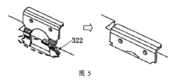
図2、図4~図5に示すように、本発明のサークリップ3は押圧部31と係止部32との間に位置する接続部33をさらに備える。本発明の一実施形態によれば、サークリップ3の係止部32の先端の側面に案内リブ322が設けられ、接続部33の側面に第2案内リブ331が設けられる。サークリップ3が案内溝12に取り付けられる場合、案内リブ322及び第2案内リブ331は案内溝12と係合し、案内の役割を果たし、サークリップ3が案内溝12内に円滑に取り付けられやすく、このようにして、サークリップ3に前後変形が発生することを回避することができ、係止部32を最終的にレンズ2の係止溝21の正確な位置に着座させることができる。
As shown in FIGS. 2, 4 and 5, the
図2に示すように、本発明の実施形態によれば、サークリップ3の接続部33は直立板状構造に設けられ、取り付け時に直立状態にある。押圧部31は接続部33と垂直に設けられ、水平状態にあり、水平押圧面を有し、このようにサークリップ3が円滑に取り付けやすくなる。
As shown in FIG. 2, according to an embodiment of the invention, the connecting
図2、図4及び図6に示すように、本発明の上筐体1は案内溝12の片側に設けられたストッパ13をさらに備える。本発明のサークリップ3は案内溝12に沿って下向きに取り付けられ、最終的にサークリップ3の押圧部31の水平押圧面をストッパ13の下に位置させてストッパに密着させる。このようにサークリップ3が取り付けされた後に振動などの要因で脱落しないことを確保することができ、常にレンズ2に対する固定、制限作用を確保することができる。
As shown in FIGS. 2, 4, and 6, the upper housing 1 of the present invention further includes a
本発明の一実施形態によれば、押圧部31に水平押圧面が設けられ、ストッパ13の下端面が同様に水平面として設けられ、このように押圧部31とストッパ13が緊密に係合することを確保することができ、制限効果を確保することができる。勿論、本発明の構想によれば、押圧面とストッパ13の下端面は上記形態に限定されるものではなく、互いに係合する円弧面などとして設けられてもよい。
According to an embodiment of the present invention, the pressing part 31 is provided with a horizontal pressing surface, and the lower end surface of the
図1及び図4に示すように、本発明の一実施形態によれば、本発明の案内溝12は上筐体1の底部に設けられ、具体的には、まず上筐体1の底部を上向きにして反転させ、続いてレンズ2を後端から上筐体1の収容部11内に取り付け、次にサークリップ3を案内溝12内に取り付け、最終的に上方から下筐体5と上筐体1をネジ、接着剤などを用いて固定接続することができる。このように、サークリップ3が取り付けられた後、本発明の撮像モジュール構造の外観に影響を与えず、防塵防水要件を満たすことができる。勿論、本発明の構想によれば、案内溝12の位置は限定されず、具体的な要件に応じて設置されてもよい。
As shown in FIGS. 1 and 4, according to one embodiment of the present invention, the
図2に示すように、本発明のサークリップ3の接続部33にさらに貫通孔332が設けられているので、取り外す必要がある時にバーブ治具を用いて貫通孔332を引っ掛けて上向きにサークリップ3を引き出せばよく、操作しやすい。一方、貫通孔332はまたサークリップの表面処理時の掛け点位置とすることができる。具体的には、サークリップの腐食を防止するために、サークリップは通常表面酸化処理を行う必要があり、この時貫通孔332を掛け点としてサークリップ3を処理することができる。
As shown in FIG. 2, since a through
図1、図4、図7及び図8に示すように、本発明のレンズ2と上筐体1の収容部11とは軸孔で係合されることにより、レンズ2の水平方向の変位を制限することができ、レンズの水平方向の位置度を確保することができる。本発明の一実施形態によれば、レンズ2の末端の外周壁には、上筐体1と係合する取付平面22が設けられているので、ポカよけや位置制限を行うことができ、レンズ2が上筐体1に挿入された後にレンズ2の取り付け間違いを防止することができ、レンズ2が取り付け及び後の使用中に回転しないことを保証することができ、現像品質を確保することができる。
As shown in FIGS. 1, 4, 7, and 8, the
図1に示すように、本発明の配線板4に感光チップが設けられ、レンズは、末端が配線板に固定して接続される。本発明では、配線板4は、回路基板と、回路基板に密着する放熱板とを備える。これにより感光チップの熱を効果的に放熱することができ、強度がより高く、変形量が小さく、レンズの温度ドリフトがより小さく、現像がより鮮明となる。放熱板は鋼片補強板、アルミニウム基板、セラミック板又は他の放熱機能に優れた材料を用いることができる。 As shown in FIG. 1, a photosensitive chip is provided on the wiring board 4 of the present invention, and the end of the lens is fixedly connected to the wiring board. In the present invention, the wiring board 4 includes a circuit board and a heat sink that is in close contact with the circuit board. As a result, the heat of the photosensitive chip can be effectively dissipated, the strength is higher, the amount of deformation is smaller, the temperature drift of the lens is smaller, and the development becomes clearer. As the heat dissipation plate, a reinforced steel plate, an aluminum substrate, a ceramic plate, or other materials with excellent heat dissipation function can be used.
本発明の一実施形態によれば、本発明におけるレンズ2は一体型レンズを採用し、接着剤でレンズを固定する従来の構造に比べ、一体型にはレンズ脱落のリスクがなく、該構造の重心が前寄りであり、振動によるレンズモジュールの光学性能への影響の可能性がより小さくなる。
According to an embodiment of the present invention, the
勿論、本発明の構想によれば、サークリップ3の係止固定の構想は他の構造、例えばレンズとレンズホルダーとの間に適用されてもよい。図9に示すように、セパレート型レンズの解決手段はサークリップを用いてレンズの前後変位を制限することができる。まずレンズ2の受け面とレンズホルダーの受け面との密着を確保するようにレンズ2をレンズホルダーに挿入し、続いてサークリップ3が折り曲げ変形することなく案内溝に沿ってレンズホルダーに入るようにサークリップ3をレンズホルダーに挿入する。サークリップを挿入した後、レンズはサークリップの持続的な反発力を受け、最後にサークリップはレンズホルダーの係着点と係着し、組み立てが完了する。
Of course, according to the concept of the invention, the concept of locking the
以上、本発明の1つの実施形態にすぎず、本発明を限定するためのものではなく、当業者であれば、本発明は様々な修正や変更が可能である。本発明の精神と原則内で、行われたいかなる修正、均等置換、改善などはいずれも本発明の保護範囲内に含まれるべきである。 The above is only one embodiment of the present invention, and is not intended to limit the present invention, and those skilled in the art can make various modifications and changes to the present invention. Any modification, equivalent replacement, improvement, etc. made within the spirit and principle of the present invention shall be included within the protection scope of the present invention.
本願は、2020年07月02日に中国特許庁に提出した、出願番号が202010634529.4、出願の名称が「撮像モジュール構造」である中国特許出願の優先権を主張し、その全ての内容は参照により本願に組み込まれている。 This application claims priority to a Chinese patent application filed with the Chinese Patent Office on July 2, 2020, with application number 202010634529.4 and the application title "Imaging module structure", and all contents thereof are Incorporated into this application by reference.
Claims (14)
前記収容部(11)に取り付けられるレンズ(2)と、を備える撮像モジュール構造であって、
押圧部(31)と、係止部(32)と、前記押圧部(31)と前記係止部(32)との間に設けられた接続部(33)と、を備えるサークリップ(3)をさらに備え、
前記上筐体(1)に案内溝(12)が設けられ、
前記レンズ(2)の外周壁に係止溝(21)が設けられ、
前記係止部(32)は、前記レンズの係止溝(21)内に係止され、
前記接続部(33)は、前記案内溝(12)に挿通されている、
ことを特徴とする撮像モジュール構造。 an upper casing (1) having a housing section (11);
An imaging module structure comprising a lens (2) attached to the housing part (11),
A circlip (3) comprising a pressing part (31) , a locking part (32), and a connecting part (33) provided between the pressing part (31) and the locking part (32). Furthermore,
A guide groove (12) is provided in the upper housing (1),
A locking groove (21) is provided on the outer peripheral wall of the lens (2),
The locking part (32) is locked in the locking groove (21) of the lens ,
The connecting portion (33) is inserted into the guide groove (12).
An imaging module structure characterized by:
前記係止部(32)が前記係止溝(21)に係止される時、前記凸台構造(321)は前記係止溝(21)内に位置することを特徴とする請求項1に記載の撮像モジュール構造。 The locking part (32) has a convex structure (321),
According to claim 1, wherein when the locking part (32) is locked in the locking groove (21), the convex structure (321) is located in the locking groove (21). Imaging module structure as described.
前記押圧部(31)は前記接続部(33)に垂直に接続され、水平押圧面を有することを特徴とする請求項4に記載の撮像モジュール構造。 The connecting portion (33) has an upright plate shape,
The imaging module structure according to claim 4, wherein the pressing part (31) is vertically connected to the connecting part (33) and has a horizontal pressing surface.
前記ストッパ(13)は前記案内溝(12)の片側に位置し、前記押圧部(31)と係合することを特徴とする請求項5に記載の撮像モジュール構造。 The upper housing (1) is further provided with a stopper (13),
The imaging module structure according to claim 5, wherein the stopper (13) is located on one side of the guide groove (12) and engages with the pressing part (31).
前記配線板(4)は、回路基板と、前記回路基板に密着する放熱板とを備えることを特徴とする請求項1に記載の撮像モジュール構造。 The lens (2) further includes a wiring board (4) on which a photosensitive chip is provided, the end of the lens (2) is fixedly connected to the wiring board (4),
The imaging module structure according to claim 1, wherein the wiring board (4) includes a circuit board and a heat sink that is in close contact with the circuit board.
Applications Claiming Priority (3)
| Application Number | Priority Date | Filing Date | Title |
|---|---|---|---|
| CN202010634529.4A CN113965667A (en) | 2020-07-02 | 2020-07-02 | Camera module structure |
| CN202010634529.4 | 2020-07-02 | ||
| PCT/CN2020/103294 WO2022000617A1 (en) | 2020-07-02 | 2020-07-21 | Camera module structure |
Publications (2)
| Publication Number | Publication Date |
|---|---|
| JP2023524306A JP2023524306A (en) | 2023-06-09 |
| JP7447313B2 true JP7447313B2 (en) | 2024-03-11 |
Family
ID=79317338
Family Applications (1)
| Application Number | Title | Priority Date | Filing Date |
|---|---|---|---|
| JP2022567450A Active JP7447313B2 (en) | 2020-07-02 | 2020-07-21 | Imaging module structure |
Country Status (6)
| Country | Link |
|---|---|
| US (1) | US20230027545A1 (en) |
| EP (1) | EP4130833A4 (en) |
| JP (1) | JP7447313B2 (en) |
| KR (1) | KR20220160113A (en) |
| CN (2) | CN113965667A (en) |
| WO (1) | WO2022000617A1 (en) |
Citations (9)
| Publication number | Priority date | Publication date | Assignee | Title |
|---|---|---|---|---|
| JP2006323079A (en) | 2005-05-18 | 2006-11-30 | Auto Network Gijutsu Kenkyusho:Kk | On-vehicle camera device |
| US20090110381A1 (en) | 2007-10-30 | 2009-04-30 | Chih-Yi Yang | Fixing structure for an auxiliary lens of cameras |
| JP2011507036A (en) | 2007-12-10 | 2011-03-03 | アーティフィシャル マッスル,インク. | Optical lens image stabilization system |
| KR20130077573A (en) | 2011-12-29 | 2013-07-09 | 삼성전기주식회사 | Camera module |
| CN206505247U (en) | 2017-02-27 | 2017-09-19 | 广东弘景光电科技股份有限公司 | Camera module auxiliary installing device |
| JP2018097225A (en) | 2016-12-15 | 2018-06-21 | 日本電産コパル株式会社 | Optical device for imaging |
| CN208172338U (en) | 2018-02-09 | 2018-11-30 | 瑞声科技(新加坡)有限公司 | lens assembly |
| CN208522861U (en) | 2018-08-30 | 2019-02-19 | Oppo广东移动通信有限公司 | Lens assembly, camera module and electronic device |
| CN212543868U (en) | 2020-07-02 | 2021-02-12 | 浙江舜宇智领技术有限公司 | Camera module structure |
Family Cites Families (5)
| Publication number | Priority date | Publication date | Assignee | Title |
|---|---|---|---|---|
| CN103661108B (en) * | 2013-12-04 | 2016-02-10 | 广东丰诺汽车安全科技有限公司 | A kind of automobile rearview camera and assemble method thereof |
| CN203961525U (en) * | 2014-07-23 | 2014-11-26 | 安徽江淮汽车股份有限公司 | A kind of electronics tail-gate switch module |
| CN106687844A (en) * | 2014-09-25 | 2017-05-17 | 日本电产科宝株式会社 | Imaging device, optical device, electronic device, vehicle, and production method for imaging device |
| KR102472860B1 (en) * | 2018-10-22 | 2022-11-30 | 현대모비스 주식회사 | Camera device for vehicle |
| CN112956181B (en) * | 2018-11-15 | 2023-08-01 | 索尼半导体解决方案公司 | Vehicle-mounted camera |
-
2020
- 2020-07-02 CN CN202010634529.4A patent/CN113965667A/en active Pending
- 2020-07-02 CN CN202310278418.8A patent/CN116419054A/en active Pending
- 2020-07-21 WO PCT/CN2020/103294 patent/WO2022000617A1/en unknown
- 2020-07-21 KR KR1020227038154A patent/KR20220160113A/en not_active Application Discontinuation
- 2020-07-21 JP JP2022567450A patent/JP7447313B2/en active Active
- 2020-07-21 EP EP20943610.4A patent/EP4130833A4/en active Pending
-
2022
- 2022-10-03 US US17/958,834 patent/US20230027545A1/en active Pending
Patent Citations (9)
| Publication number | Priority date | Publication date | Assignee | Title |
|---|---|---|---|---|
| JP2006323079A (en) | 2005-05-18 | 2006-11-30 | Auto Network Gijutsu Kenkyusho:Kk | On-vehicle camera device |
| US20090110381A1 (en) | 2007-10-30 | 2009-04-30 | Chih-Yi Yang | Fixing structure for an auxiliary lens of cameras |
| JP2011507036A (en) | 2007-12-10 | 2011-03-03 | アーティフィシャル マッスル,インク. | Optical lens image stabilization system |
| KR20130077573A (en) | 2011-12-29 | 2013-07-09 | 삼성전기주식회사 | Camera module |
| JP2018097225A (en) | 2016-12-15 | 2018-06-21 | 日本電産コパル株式会社 | Optical device for imaging |
| CN206505247U (en) | 2017-02-27 | 2017-09-19 | 广东弘景光电科技股份有限公司 | Camera module auxiliary installing device |
| CN208172338U (en) | 2018-02-09 | 2018-11-30 | 瑞声科技(新加坡)有限公司 | lens assembly |
| CN208522861U (en) | 2018-08-30 | 2019-02-19 | Oppo广东移动通信有限公司 | Lens assembly, camera module and electronic device |
| CN212543868U (en) | 2020-07-02 | 2021-02-12 | 浙江舜宇智领技术有限公司 | Camera module structure |
Also Published As
| Publication number | Publication date |
|---|---|
| KR20220160113A (en) | 2022-12-05 |
| EP4130833A4 (en) | 2024-04-17 |
| JP2023524306A (en) | 2023-06-09 |
| WO2022000617A1 (en) | 2022-01-06 |
| CN113965667A (en) | 2022-01-21 |
| EP4130833A1 (en) | 2023-02-08 |
| US20230027545A1 (en) | 2023-01-26 |
| CN116419054A (en) | 2023-07-11 |
Similar Documents
| Publication | Publication Date | Title |
|---|---|---|
| JP2003042882A (en) | Pressure sensor mounting structure | |
| JP2000258756A (en) | Liquid crystal module | |
| CN212543868U (en) | Camera module structure | |
| JP7447313B2 (en) | Imaging module structure | |
| JP4019381B2 (en) | Liquid crystal television and liquid crystal display device | |
| JP4483569B2 (en) | Liquid crystal display | |
| JP2002347521A (en) | Mirror face angle adjustment mechanism | |
| JP2012004692A (en) | Display device | |
| JPWO2005017858A1 (en) | Display panel mounting structure | |
| JP2010081293A (en) | Camera module | |
| JP3901545B2 (en) | Housing with fitting structure | |
| JP2002280766A (en) | Board holding mechanism in general purpose personal computer | |
| JPH09281539A (en) | Camera | |
| CN212276159U (en) | Liquid crystal display device | |
| KR100707012B1 (en) | Apparatus for settling liquid crystal display module on portable appliances | |
| JP2008016333A (en) | Method and structure of mounting base board with hdmi connector | |
| JP3321073B2 (en) | Instrument movement mounting structure | |
| JP4139406B2 (en) | Semiconductor device | |
| JP2722909B2 (en) | Semiconductor device | |
| JPH06188576A (en) | Mechanism for mounting electronic equipment | |
| JP2980014B2 (en) | Optical disk drive mounting device | |
| CN117650217A (en) | Light source device and method for assembling light source device | |
| KR20220128072A (en) | Steering shaft temporary support structure of vehicle | |
| JP2023080124A (en) | display device | |
| JPH11160108A (en) | Instrument case installation device |
Legal Events
| Date | Code | Title | Description |
|---|---|---|---|
| A621 | Written request for application examination |
Free format text: JAPANESE INTERMEDIATE CODE: A621 Effective date: 20221107 |
|
| A131 | Notification of reasons for refusal |
Free format text: JAPANESE INTERMEDIATE CODE: A131 Effective date: 20231003 |
|
| A521 | Request for written amendment filed |
Free format text: JAPANESE INTERMEDIATE CODE: A523 Effective date: 20231205 |
|
| TRDD | Decision of grant or rejection written | ||
| A01 | Written decision to grant a patent or to grant a registration (utility model) |
Free format text: JAPANESE INTERMEDIATE CODE: A01 Effective date: 20240227 |
|
| A61 | First payment of annual fees (during grant procedure) |
Free format text: JAPANESE INTERMEDIATE CODE: A61 Effective date: 20240228 |
|
| R150 | Certificate of patent or registration of utility model |
Ref document number: 7447313 Country of ref document: JP Free format text: JAPANESE INTERMEDIATE CODE: R150 |