EP4130833A1 - Camera module structure - Google Patents
Camera module structure Download PDFInfo
- Publication number
- EP4130833A1 EP4130833A1 EP20943610.4A EP20943610A EP4130833A1 EP 4130833 A1 EP4130833 A1 EP 4130833A1 EP 20943610 A EP20943610 A EP 20943610A EP 4130833 A1 EP4130833 A1 EP 4130833A1
- Authority
- EP
- European Patent Office
- Prior art keywords
- lens
- camera module
- module structure
- present disclosure
- structure according
- Prior art date
- Legal status (The legal status is an assumption and is not a legal conclusion. Google has not performed a legal analysis and makes no representation as to the accuracy of the status listed.)
- Granted
Links
Images
Classifications
-
- G—PHYSICS
- G03—PHOTOGRAPHY; CINEMATOGRAPHY; ANALOGOUS TECHNIQUES USING WAVES OTHER THAN OPTICAL WAVES; ELECTROGRAPHY; HOLOGRAPHY
- G03B—APPARATUS OR ARRANGEMENTS FOR TAKING PHOTOGRAPHS OR FOR PROJECTING OR VIEWING THEM; APPARATUS OR ARRANGEMENTS EMPLOYING ANALOGOUS TECHNIQUES USING WAVES OTHER THAN OPTICAL WAVES; ACCESSORIES THEREFOR
- G03B17/00—Details of cameras or camera bodies; Accessories therefor
- G03B17/02—Bodies
-
- G—PHYSICS
- G03—PHOTOGRAPHY; CINEMATOGRAPHY; ANALOGOUS TECHNIQUES USING WAVES OTHER THAN OPTICAL WAVES; ELECTROGRAPHY; HOLOGRAPHY
- G03B—APPARATUS OR ARRANGEMENTS FOR TAKING PHOTOGRAPHS OR FOR PROJECTING OR VIEWING THEM; APPARATUS OR ARRANGEMENTS EMPLOYING ANALOGOUS TECHNIQUES USING WAVES OTHER THAN OPTICAL WAVES; ACCESSORIES THEREFOR
- G03B30/00—Camera modules comprising integrated lens units and imaging units, specially adapted for being embedded in other devices, e.g. mobile phones or vehicles
-
- G—PHYSICS
- G02—OPTICS
- G02B—OPTICAL ELEMENTS, SYSTEMS OR APPARATUS
- G02B7/00—Mountings, adjusting means, or light-tight connections, for optical elements
- G02B7/02—Mountings, adjusting means, or light-tight connections, for optical elements for lenses
-
- G—PHYSICS
- G02—OPTICS
- G02B—OPTICAL ELEMENTS, SYSTEMS OR APPARATUS
- G02B7/00—Mountings, adjusting means, or light-tight connections, for optical elements
- G02B7/02—Mountings, adjusting means, or light-tight connections, for optical elements for lenses
- G02B7/026—Mountings, adjusting means, or light-tight connections, for optical elements for lenses using retaining rings or springs
-
- G—PHYSICS
- G03—PHOTOGRAPHY; CINEMATOGRAPHY; ANALOGOUS TECHNIQUES USING WAVES OTHER THAN OPTICAL WAVES; ELECTROGRAPHY; HOLOGRAPHY
- G03B—APPARATUS OR ARRANGEMENTS FOR TAKING PHOTOGRAPHS OR FOR PROJECTING OR VIEWING THEM; APPARATUS OR ARRANGEMENTS EMPLOYING ANALOGOUS TECHNIQUES USING WAVES OTHER THAN OPTICAL WAVES; ACCESSORIES THEREFOR
- G03B17/00—Details of cameras or camera bodies; Accessories therefor
- G03B17/56—Accessories
- G03B17/563—Camera grips, handles
-
- H—ELECTRICITY
- H04—ELECTRIC COMMUNICATION TECHNIQUE
- H04N—PICTORIAL COMMUNICATION, e.g. TELEVISION
- H04N23/00—Cameras or camera modules comprising electronic image sensors; Control thereof
- H04N23/50—Constructional details
-
- H—ELECTRICITY
- H04—ELECTRIC COMMUNICATION TECHNIQUE
- H04N—PICTORIAL COMMUNICATION, e.g. TELEVISION
- H04N23/00—Cameras or camera modules comprising electronic image sensors; Control thereof
- H04N23/50—Constructional details
- H04N23/51—Housings
-
- H—ELECTRICITY
- H04—ELECTRIC COMMUNICATION TECHNIQUE
- H04N—PICTORIAL COMMUNICATION, e.g. TELEVISION
- H04N23/00—Cameras or camera modules comprising electronic image sensors; Control thereof
- H04N23/50—Constructional details
- H04N23/52—Elements optimising image sensor operation, e.g. for electromagnetic interference [EMI] protection or temperature control by heat transfer or cooling elements
-
- H—ELECTRICITY
- H04—ELECTRIC COMMUNICATION TECHNIQUE
- H04N—PICTORIAL COMMUNICATION, e.g. TELEVISION
- H04N23/00—Cameras or camera modules comprising electronic image sensors; Control thereof
- H04N23/50—Constructional details
- H04N23/55—Optical parts specially adapted for electronic image sensors; Mounting thereof
-
- G—PHYSICS
- G03—PHOTOGRAPHY; CINEMATOGRAPHY; ANALOGOUS TECHNIQUES USING WAVES OTHER THAN OPTICAL WAVES; ELECTROGRAPHY; HOLOGRAPHY
- G03B—APPARATUS OR ARRANGEMENTS FOR TAKING PHOTOGRAPHS OR FOR PROJECTING OR VIEWING THEM; APPARATUS OR ARRANGEMENTS EMPLOYING ANALOGOUS TECHNIQUES USING WAVES OTHER THAN OPTICAL WAVES; ACCESSORIES THEREFOR
- G03B17/00—Details of cameras or camera bodies; Accessories therefor
- G03B17/55—Details of cameras or camera bodies; Accessories therefor with provision for heating or cooling, e.g. in aircraft
Definitions
- the present disclosure belongs to the technical field of optics, and in particular relates to an on-vehicle camera module structure.
- the application of cameras in the assistance system plays a significant role.
- functions such as adaptive cruise control, blind spot detection, collision avoidance, and parking assistance can be realized.
- positional relationships between the camera modules and the automobile are very important, and whether the camera modules are well fixed directly determines the effects of the above functions and whether these functions can succeed or not.
- the cameras are fixed mainly through screw connection, snap-fit connection, glue connection or the like.
- the screw connection, snap-fit connection and glue connection may have the risk of failure such as loosening, shaking and falling off or fracture.
- the above ways of connection require many structural parts, the assembly is complicated, and the cost is high.
- An object of the present disclosure is to provide a camera module structure, so as to solve the problems of loosening, shaking and falling off in the existing ways of fixing the cameras.
- the present disclosure provides a camera module structure, which includes an upper casing and a lens; the upper casing has an accommodation part in which the lens is installed; the camera module structure further includes a circlip, which includes a pressing part and clamping parts; the upper casing is provided with a guide groove, an outer peripheral wall of the lens is provided with a clamping groove, and the clamping parts are clamped in the clamping groove of the lens along the guide groove.
- the clamping parts have boss structures, and when the clamping parts are clamped in the clamping groove, the boss structures are located in the clamping groove.
- a guide rib matching with the guide groove is provided on a side face at a front end of the clamping part.
- connection part is further provided between the pressing part and the clamping parts; and a side edge of the connection part is provided with a second guide rib matching with the guide groove.
- connection part is in the shape of a vertical plate
- pressing part is perpendicularly connected to the connection part and has a horizontal pressing surface
- the upper casing is further provided with a limiting block, and the limiting block is located on one side of the guide groove and cooperates with the pressing part.
- the guide groove is provided at a bottom of the upper casing.
- connection part is provided with a through hole.
- the circlip is made of a material of carbon steel or spring steel.
- the lens and the accommodation part of the upper casing match with each other through shaft and hole.
- an installation plane is arranged on a peripheral wall at a terminal end of the lens to match with the upper casing.
- the lens is an integral lens.
- the camera module structure further includes a circuit board on which a photosensitive chip is arranged, and a terminal end of the lens is fixedly connected with the circuit board; and the circuit board includes a circuit substrate and a heat dissipation plate abutting against the circuit substrate.
- the camera module structure further includes a lower casing which is connected with the upper casing.
- the circlip of the present disclosure includes a pressing part and clamping parts
- the upper casing is further provided with a guide groove
- the outer peripheral wall of the lens is provided with a clamping groove
- the circlip of the present disclosure can be placed in the guide groove.
- bosses are provided on the clamping parts of the circlip of the present disclosure, and when the clamping parts are clamped in the clamping groove of the lens, the bosses are located in the clamping groove, so that a force can be exerted on the lens in the horizontal direction to ensure that the lens will not be displaced in the horizontal direction and guarantee the positional accuracy of the lens.
- a guide rib is provided on a side face at a front end of the clamping part of the circlip, and a second guide rib is provided on a side face of the connection part.
- the lens of the present disclosure and the accommodation part of the upper casing match with each other through shaft and hole, so that a displacement of the lens in the horizontal direction can be limited and the position degree of the lens in the horizontal direction can be ensured.
- an installation plane is provided on an outer peripheral wall at a terminal end of the lens to match with the upper casing, so as to realize fool-proofing and position limiting. After the lens is inserted into the upper casing, the wrong installation of the lens can be prevented, and it can be ensured that the lens will not rotate during installation and subsequent use, thus ensuring the imaging quality.
- the terminal end of the lens is fixedly connected with the circuit board.
- the circuit board includes a circuit substrate and a heat dissipation plate abutting against the circuit substrate.
- the lens in the present disclosure is an integral lens.
- the lens does not have the risk of falling off due to the integral structure, and the center of gravity of the structure is located near the front, so it is less likely for the shaking to have an influence on the optical performance of the lens module.
- orientations or positional relationships described by the terms “longitudinal”, “transverse”, “upper”, “lower”, “front”, “rear”, “left”, “right”, “vertical”, “horizontal”, “top”, “bottom”, “inner” and “outer” are based on the orientations or positional relationships shown in the related drawings. These terms are merely used for the sake of facilitating describing the present disclosure and simplifying the description, and do not indicate or imply that the device or element involved must have a particular orientation, or must be constructed or operated in a particular orientation. Therefore, the above terms should not be construed as limiting the present disclosure.
- the camera module structure of the present disclosure includes an upper casing 1, a lens 2, a circlip 3, a circuit board 4 and a lower casing 5.
- the upper casing 1 is provided with an accommodation part 11, and the lens 2 of the present disclosure is installed in the accommodation part 11 of the upper casing 1.
- the circlip 3 of the present disclosure includes a pressing part 31 and clamping parts 32; the upper casing 1 is further provided with a guide groove 12, and an outer peripheral wall of the lens 2 is provided with a clamping groove 21.
- the circlip 3 of the present disclosure can be placed in the guide groove 12, and by pressing the pressing part 31 of the circlip 3, the clamping parts 32 of the circlip 3 are finally clamped in the clamping groove 21 of the lens 2, so that the position of the lens 2 in the camera module can be fixed.
- connection means in the prior art such as glue connection and screw connection
- problems such as loosening, falling off and fracture, which is advantageous for ensuring the imaging quality and service life of the lens.
- the circlip 3 is provided in the present disclosure to fix the lens 2, which makes the assembly operation easier and faster as compared with the glue connection and screw connection.
- the clamping parts 32 of the circlip 3 of the present disclosure are provided with boss structures 321, and when the clamping parts 32 are clamped in the clamping groove 21 of the lens 2, the boss structures 321 are located inside the clamping groove 21.
- the clamping groove 21 is arranged into a vertical shape.
- the boss structures 321 are configured as circular arc-shaped bosses.
- the bosses 321 are located inside the clamping groove 21, and can exert a force on the lens 2 in the horizontal direction to ensure that the lens 2 will not be displaced in the horizontal direction and guarantee the positional accuracy of the lens 2.
- the shape of the clamping groove 21 is not limited. According to other embodiments of the present disclosure, the clamping groove 21 can be provided as a groove with a certain inclination angle, and the corresponding circlip 3 also has a deflection angle. Through such an arrangement, the lens can also be fixed and limited.
- the circlip 3 is made of carbon steel material or a material with elasticity such as spring steel.
- the elasticity of the circlip 3 has to be different at different positions.
- the requirement on the elasticity is the highest at the boss structures 321.
- the thickness can be made thinner at the boss structures 321 so that it is smaller than the thickness at the pressing part 31 of the circlip 3 to further improve the elasticity.
- the circlip 3 of the present disclosure further includes a connection part 33, and the connection part 33 is located between the pressing part 31 and the clamping parts 32.
- a guide rib 322 is provided on a side face at a front end of the clamping part 32 of the circlip 3
- a second guide rib 331 is provided on a side face of the connection part 33.
- the guide rib 322 and the second guide rib 331 cooperate with the guide groove 12 to play a guiding role, which facilitates a smooth installation of the circlip 3 into the guide groove 12, prevents the circlip 3 from being deformed back and forth, and enables the clamping parts 32 to finally fall into the correct position in the clamping groove 21 of the lens 2.
- connection part 33 of the circlip 3 is provided as a vertical plate-like structure, and is in a vertical state during installation.
- the pressing part 31 is arranged perpendicular to the connection part 33, is in a horizontal state, and has a horizontal pressing surface, thus facilitating a smooth installation of the circlip 3.
- the upper casing 1 of the present disclosure is further provided with a limiting block 13, and the limiting block 13 is arranged on one side of the guide groove 12.
- the circlip 3 of the present disclosure is installed downward along the guide groove 12, and finally the horizontal pressing surface of the pressing part 31 of the circlip 3 is located below the limiting block 13 and abuts against the limiting block. As such, it can be ensured that the circlip 3 will not fall off due to shaking and other factors after installation, and the fixing and limiting effect on the lens 2 can always be guaranteed.
- the pressing part 31 is provided with a horizontal pressing surface, and a lower end face of the limiting block 13 is also provided as a horizontal surface, so as to ensure that the pressing part 31 and the limiting block 13 can closely cooperate with each other to guarantee the limiting effect.
- the pressing surface and the lower end face of the limiting block 13 are not limited to the above arrangement, and they can also be configured as arc-shaped surfaces that cooperate with each other, etc.
- the guide groove 12 of the present disclosure is arranged at the bottom of the upper casing 1.
- the upper casing 1 can be turned over first so that the bottom thereof faces upward, then the lens 2 is installed into the accommodation part 11 of the upper casing 1 from a rear end, next the circlip 3 is installed into the guide groove 12, and finally the lower casing 5 is fixedly connected to the upper casing 1 from above by means of screw, glue, etc.
- the arrangement position of the guide groove 12 is not limited, and can be set according to specific requirements.
- connection part 33 of the circlip 3 of the present disclosure is also provided with a through hole 332. Therefore, when disassembly is required, a barb jig can be used to hook the through hole 332 so that the circlip 3 can be pulled out upward. The operation is convenient.
- the through hole 332 can also be used as a hanging point position during surface treatment of the circlip. Specifically, in order to prevent rusting of the circlip, the circlip usually has to undergo surface oxidation treatment. At this time, the through hole 322 can be used as the hanging point for the treatment of the circlip 3.
- the lens 2 of the present disclosure and the accommodation part 11 of the upper casing 1 match with each other through shaft and hole, so that a displacement of the lens 2 in the horizontal direction can be limited and the position degree of the lens in the horizontal direction can be ensured.
- an installation plane 22 is provided on an outer peripheral wall at a terminal end of the lens 2 to match with the upper casing 1, so as to realize fool-proofing and position limiting. After the lens 2 is inserted into the upper casing 1, the wrong installation of the lens 2 can be prevented, and it can be ensured that the lens 2 will not rotate during installation and subsequent use, thus ensuring the imaging quality.
- the circuit board 4 of the present disclosure is provided with a photosensitive chip, and the terminal end of the lens is fixedly connected with the circuit board.
- the circuit board 4 includes a circuit substrate and a heat dissipation plate abutting against the circuit substrate.
- the heat dissipation plate may be a steel reinforced plate, an aluminum plate, or a ceramic plate, or may be made of other materials with a good heat dissipation function.
- the lens 2 in the present disclosure is an integral lens. As compared with the traditional structure of fixing the lens by applying glue, the lens does not have the risk of falling off due to the integral structure, and the center of gravity of the structure is located near the front, so it is less likely for the shaking to have an influence on the optical performance of the lens module.
- the idea of clamping and fixing through the circlip 3 can also be applied to other structures, such as between the lens and a lens base.
- the circlip can be used to limit the front-and-rear displacement of the lens.
- the lens 2 is inserted into the lens base to ensure that a bearing surface of the lens 2 closely abuts against a bearing surface in the lens base, and then the circlip 3 is inserted into the lens base, so that the circlip 3 can enter the lens base along the guide groove without bending or deforming.
- the lens is subjected to a continuous rebounding force of the circlip, and finally the circlip is snap-fit at a snap-fit point of the lens base, thus completing the assembly.
Landscapes
- Physics & Mathematics (AREA)
- Engineering & Computer Science (AREA)
- General Physics & Mathematics (AREA)
- Multimedia (AREA)
- Signal Processing (AREA)
- Aviation & Aerospace Engineering (AREA)
- Optics & Photonics (AREA)
- Electromagnetism (AREA)
- Lens Barrels (AREA)
- Fittings On The Vehicle Exterior For Carrying Loads, And Devices For Holding Or Mounting Articles (AREA)
Abstract
Description
- The present application claims priority to
Chinese patent application No. 202010634529.4, titled "CAMERA MODULE STRUCTURE", filed with the Chinese National Intellectual Property Administration on July 2, 2020 - The present disclosure belongs to the technical field of optics, and in particular relates to an on-vehicle camera module structure.
- Nowadays, as the automobile industry is developing towards autonomous driving, automotive R&D personnel are increasingly focusing on active safety of automotive systems. To achieve active safety and autonomous driving, an advanced driver assistance system is the basis and also the key.
- The application of cameras in the assistance system plays a significant role. Through front-view, rear-view, side-view, 360 degree-all-around-view camera modules and the like, functions such as adaptive cruise control, blind spot detection, collision avoidance, and parking assistance can be realized. To realize these functions, positional relationships between the camera modules and the automobile are very important, and whether the camera modules are well fixed directly determines the effects of the above functions and whether these functions can succeed or not.
- Traditionally, the cameras are fixed mainly through screw connection, snap-fit connection, glue connection or the like. With the increase of use time, the screw connection, snap-fit connection and glue connection may have the risk of failure such as loosening, shaking and falling off or fracture. In addition, the above ways of connection require many structural parts, the assembly is complicated, and the cost is high.
- An object of the present disclosure is to provide a camera module structure, so as to solve the problems of loosening, shaking and falling off in the existing ways of fixing the cameras.
- In order to achieve the above object, the present disclosure provides a camera module structure, which includes an upper casing and a lens; the upper casing has an accommodation part in which the lens is installed; the camera module structure further includes a circlip, which includes a pressing part and clamping parts; the upper casing is provided with a guide groove, an outer peripheral wall of the lens is provided with a clamping groove, and the clamping parts are clamped in the clamping groove of the lens along the guide groove.
- According to an aspect of the present disclosure, the clamping parts have boss structures, and when the clamping parts are clamped in the clamping groove, the boss structures are located in the clamping groove.
- According to an aspect of the present disclosure, a guide rib matching with the guide groove is provided on a side face at a front end of the clamping part.
- According to an aspect of the present disclosure, a connection part is further provided between the pressing part and the clamping parts; and
a side edge of the connection part is provided with a second guide rib matching with the guide groove. - According to an aspect of the present disclosure, the connection part is in the shape of a vertical plate, and the pressing part is perpendicularly connected to the connection part and has a horizontal pressing surface.
- According to an aspect of the present disclosure, the upper casing is further provided with a limiting block, and the limiting block is located on one side of the guide groove and cooperates with the pressing part.
- According to an aspect of the present disclosure, the guide groove is provided at a bottom of the upper casing.
- According to an aspect of the present disclosure, the connection part is provided with a through hole.
- According to an aspect of the present disclosure, the circlip is made of a material of carbon steel or spring steel.
- According to an aspect of the present disclosure, the lens and the accommodation part of the upper casing match with each other through shaft and hole.
- According to an aspect of the present disclosure, an installation plane is arranged on a peripheral wall at a terminal end of the lens to match with the upper casing.
- According to an aspect of the present disclosure, the lens is an integral lens.
- According to an aspect of the present disclosure, the camera module structure further includes a circuit board on which a photosensitive chip is arranged, and a terminal end of the lens is fixedly connected with the circuit board; and
the circuit board includes a circuit substrate and a heat dissipation plate abutting against the circuit substrate. - According to an aspect of the present disclosure, the camera module structure further includes a lower casing which is connected with the upper casing.
- According to a solution of the present disclosure, the circlip of the present disclosure includes a pressing part and clamping parts, the upper casing is further provided with a guide groove, the outer peripheral wall of the lens is provided with a clamping groove, and the circlip of the present disclosure can be placed in the guide groove. By pressing the pressing part of the circlip, the clamping parts of the circlip are finally clamped in the clamping groove of the lens, so that the position of the lens in the camera module can be fixed. As compared with the connection means in the prior art such as glue connection and screw connection, there will be no problems such as loosening, falling off, and fracture, which is advantageous for ensuring the imaging quality and service life of the lens. In addition, the circlip is provided in the present disclosure to fix the lens, which makes the assembly operation easier and faster as compared with the glue connection and screw connection.
- According to a solution of the present disclosure, bosses are provided on the clamping parts of the circlip of the present disclosure, and when the clamping parts are clamped in the clamping groove of the lens, the bosses are located in the clamping groove, so that a force can be exerted on the lens in the horizontal direction to ensure that the lens will not be displaced in the horizontal direction and guarantee the positional accuracy of the lens.
- According to a solution of the present disclosure, a guide rib is provided on a side face at a front end of the clamping part of the circlip, and a second guide rib is provided on a side face of the connection part. When installing the circlip into the guide groove, the guide rib and the second guide rib cooperate with the guide groove to play a guiding role, which facilitates a smooth installation of the circlip into the guide groove, prevents the circlip from being swung and deformed back and forth, and enables the clamping parts to finally fall into the correct position in the clamping groove of the lens.
- According to a solution of the present disclosure, the lens of the present disclosure and the accommodation part of the upper casing match with each other through shaft and hole, so that a displacement of the lens in the horizontal direction can be limited and the position degree of the lens in the horizontal direction can be ensured. According to an embodiment of the present disclosure, an installation plane is provided on an outer peripheral wall at a terminal end of the lens to match with the upper casing, so as to realize fool-proofing and position limiting. After the lens is inserted into the upper casing, the wrong installation of the lens can be prevented, and it can be ensured that the lens will not rotate during installation and subsequent use, thus ensuring the imaging quality.
- According to a solution of the present disclosure, the terminal end of the lens is fixedly connected with the circuit board. In the present disclosure, the circuit board includes a circuit substrate and a heat dissipation plate abutting against the circuit substrate. As a result, the heat of the photosensitive chip can be effectively dissipated; moreover, the strength is better, the deformation amount is small, the temperature drift of the lens is smaller, and the image is clearer.
- According to a solution of the present disclosure, the lens in the present disclosure is an integral lens. As compared with the traditional structure of fixing the lens by applying glue, the lens does not have the risk of falling off due to the integral structure, and the center of gravity of the structure is located near the front, so it is less likely for the shaking to have an influence on the optical performance of the lens module.
-
-
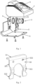
FIG. 1 schematically shows a component view of a camera module structure according to an embodiment of the present disclosure; -
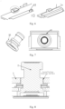
FIG. 2 schematically shows a structural view of a circlip according to an embodiment of the present disclosure; -
FIG. 3 schematically shows a cross-sectional view of a lens, the circlip and an upper casing after assembly according to the present disclosure; -
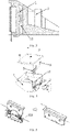
FIG. 4 schematically shows a component view of the camera module structure according to an embodiment of the present disclosure; -
FIG. 5 schematically shows an installation view of the circlip according to the present disclosure; -
FIG. 6 schematically shows a view of the cooperation between the circlip and a limiting block according to the present disclosure; -
FIG. 7 schematically shows a structural view of the lens according to an embodiment of the present disclosure; -
FIG. 8 schematically shows a cross-sectional view of the assembly of the lens and the upper casing according to an embodiment of the present disclosure; and -
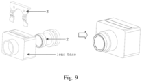
FIG. 9 schematically shows an assembly view when the circlip according to the present disclosure is applied to the lens and a lens base. - In order to more clearly illustrate the embodiments of the present disclosure or the technical solutions in the prior art, drawings required to be used in the embodiments will be briefly described below. Obviously, the drawings in the following description show only some of the embodiments of the present disclosure, and those skilled in the art can also obtain other drawings based on these drawings without creative efforts.
- When describing the embodiments of the present disclosure, the orientations or positional relationships described by the terms "longitudinal", "transverse", "upper", "lower", "front", "rear", "left", "right", "vertical", "horizontal", "top", "bottom", "inner" and "outer" are based on the orientations or positional relationships shown in the related drawings. These terms are merely used for the sake of facilitating describing the present disclosure and simplifying the description, and do not indicate or imply that the device or element involved must have a particular orientation, or must be constructed or operated in a particular orientation. Therefore, the above terms should not be construed as limiting the present disclosure.
- The present disclosure will be described in detail below with reference to the drawings and specific embodiments. It is impossible to describe all the embodiments exhaustively herein, but the embodiments of the present disclosure are not limited to the following embodiments.
- As shown in
FIGS. 1 to 8 , the camera module structure of the present disclosure includes an upper casing 1, alens 2, acirclip 3, acircuit board 4 and alower casing 5. - In the present disclosure, the upper casing 1 is provided with an
accommodation part 11, and thelens 2 of the present disclosure is installed in theaccommodation part 11 of the upper casing 1. As shown inFIGS. 2 to 3 , thecirclip 3 of the present disclosure includes apressing part 31 and clampingparts 32; the upper casing 1 is further provided with aguide groove 12, and an outer peripheral wall of thelens 2 is provided with a clampinggroove 21. Thecirclip 3 of the present disclosure can be placed in theguide groove 12, and by pressing thepressing part 31 of thecirclip 3, the clampingparts 32 of thecirclip 3 are finally clamped in the clampinggroove 21 of thelens 2, so that the position of thelens 2 in the camera module can be fixed. As compared with the connection means in the prior art such as glue connection and screw connection, there will be no problems such as loosening, falling off and fracture, which is advantageous for ensuring the imaging quality and service life of the lens. In addition, thecirclip 3 is provided in the present disclosure to fix thelens 2, which makes the assembly operation easier and faster as compared with the glue connection and screw connection. - As shown in
FIGS. 2 and3 , the clampingparts 32 of thecirclip 3 of the present disclosure are provided withboss structures 321, and when the clampingparts 32 are clamped in the clampinggroove 21 of thelens 2, theboss structures 321 are located inside the clampinggroove 21. In this embodiment, the clampinggroove 21 is arranged into a vertical shape. Theboss structures 321 are configured as circular arc-shaped bosses. Thebosses 321 are located inside the clampinggroove 21, and can exert a force on thelens 2 in the horizontal direction to ensure that thelens 2 will not be displaced in the horizontal direction and guarantee the positional accuracy of thelens 2. - According to the concept of the present disclosure, the shape of the clamping
groove 21 is not limited. According to other embodiments of the present disclosure, the clampinggroove 21 can be provided as a groove with a certain inclination angle, and thecorresponding circlip 3 also has a deflection angle. Through such an arrangement, the lens can also be fixed and limited. - In the present disclosure, the
circlip 3 is made of carbon steel material or a material with elasticity such as spring steel. Of course, according to the concept of the present disclosure, in order to ensure the fixing effect of the circlip on thelens 2, the elasticity of thecirclip 3 has to be different at different positions. The requirement on the elasticity is the highest at theboss structures 321. According to an embodiment of the present disclosure, the thickness can be made thinner at theboss structures 321 so that it is smaller than the thickness at thepressing part 31 of thecirclip 3 to further improve the elasticity. - As shown in
FIGS. 2 ,4 and 5 , thecirclip 3 of the present disclosure further includes aconnection part 33, and theconnection part 33 is located between thepressing part 31 and the clampingparts 32. According to an embodiment of the present disclosure, aguide rib 322 is provided on a side face at a front end of the clampingpart 32 of thecirclip 3, and asecond guide rib 331 is provided on a side face of theconnection part 33. When installing thecirclip 3 into theguide groove 12, theguide rib 322 and thesecond guide rib 331 cooperate with theguide groove 12 to play a guiding role, which facilitates a smooth installation of thecirclip 3 into theguide groove 12, prevents thecirclip 3 from being deformed back and forth, and enables the clampingparts 32 to finally fall into the correct position in the clampinggroove 21 of thelens 2. - As shown in
FIG. 2 , according to an embodiment of the present disclosure, theconnection part 33 of thecirclip 3 is provided as a vertical plate-like structure, and is in a vertical state during installation. Thepressing part 31 is arranged perpendicular to theconnection part 33, is in a horizontal state, and has a horizontal pressing surface, thus facilitating a smooth installation of thecirclip 3. - As shown in
FIGS. 2 ,4 and6 , the upper casing 1 of the present disclosure is further provided with a limitingblock 13, and the limitingblock 13 is arranged on one side of theguide groove 12. Thecirclip 3 of the present disclosure is installed downward along theguide groove 12, and finally the horizontal pressing surface of thepressing part 31 of thecirclip 3 is located below the limitingblock 13 and abuts against the limiting block. As such, it can be ensured that thecirclip 3 will not fall off due to shaking and other factors after installation, and the fixing and limiting effect on thelens 2 can always be guaranteed. - According to an embodiment of the present disclosure, the
pressing part 31 is provided with a horizontal pressing surface, and a lower end face of the limitingblock 13 is also provided as a horizontal surface, so as to ensure that thepressing part 31 and the limitingblock 13 can closely cooperate with each other to guarantee the limiting effect. Of course, according to the concept of the present disclosure, the pressing surface and the lower end face of the limitingblock 13 are not limited to the above arrangement, and they can also be configured as arc-shaped surfaces that cooperate with each other, etc. - As shown in
FIGS. 1 and4 , according to an embodiment of the present disclosure, theguide groove 12 of the present disclosure is arranged at the bottom of the upper casing 1. Specifically, the upper casing 1 can be turned over first so that the bottom thereof faces upward, then thelens 2 is installed into theaccommodation part 11 of the upper casing 1 from a rear end, next thecirclip 3 is installed into theguide groove 12, and finally thelower casing 5 is fixedly connected to the upper casing 1 from above by means of screw, glue, etc. In this way, after thecirclip 3 is installed, the appearance of the camera module structure of the present disclosure will not be affected, and the dustproof and waterproof requirements can be met. Of course, according to the concept of the present disclosure, the arrangement position of theguide groove 12 is not limited, and can be set according to specific requirements. - As shown in
FIG. 2 , theconnection part 33 of thecirclip 3 of the present disclosure is also provided with a throughhole 332. Therefore, when disassembly is required, a barb jig can be used to hook the throughhole 332 so that thecirclip 3 can be pulled out upward. The operation is convenient. On the other hand, the throughhole 332 can also be used as a hanging point position during surface treatment of the circlip. Specifically, in order to prevent rusting of the circlip, the circlip usually has to undergo surface oxidation treatment. At this time, the throughhole 322 can be used as the hanging point for the treatment of thecirclip 3. - As shown in
FIGS. 1 ,4 ,7 and 8 , thelens 2 of the present disclosure and theaccommodation part 11 of the upper casing 1 match with each other through shaft and hole, so that a displacement of thelens 2 in the horizontal direction can be limited and the position degree of the lens in the horizontal direction can be ensured. According to an embodiment of the present disclosure, aninstallation plane 22 is provided on an outer peripheral wall at a terminal end of thelens 2 to match with the upper casing 1, so as to realize fool-proofing and position limiting. After thelens 2 is inserted into the upper casing 1, the wrong installation of thelens 2 can be prevented, and it can be ensured that thelens 2 will not rotate during installation and subsequent use, thus ensuring the imaging quality. - As shown in
FIG. 1 , thecircuit board 4 of the present disclosure is provided with a photosensitive chip, and the terminal end of the lens is fixedly connected with the circuit board. In the present disclosure, thecircuit board 4 includes a circuit substrate and a heat dissipation plate abutting against the circuit substrate. As a result, the heat of the photosensitive chip can be effectively dissipated; moreover, the strength is better, the deformation amount is small, the temperature drift of the lens is smaller, and the image is clearer. The heat dissipation plate may be a steel reinforced plate, an aluminum plate, or a ceramic plate, or may be made of other materials with a good heat dissipation function. - According to an embodiment of the present disclosure, the
lens 2 in the present disclosure is an integral lens. As compared with the traditional structure of fixing the lens by applying glue, the lens does not have the risk of falling off due to the integral structure, and the center of gravity of the structure is located near the front, so it is less likely for the shaking to have an influence on the optical performance of the lens module. - Of course, according to the concept of the present disclosure, the idea of clamping and fixing through the
circlip 3 can also be applied to other structures, such as between the lens and a lens base. As shown inFIG. 9 , for a split lens solution, the circlip can be used to limit the front-and-rear displacement of the lens. First, thelens 2 is inserted into the lens base to ensure that a bearing surface of thelens 2 closely abuts against a bearing surface in the lens base, and then thecirclip 3 is inserted into the lens base, so that thecirclip 3 can enter the lens base along the guide groove without bending or deforming. After the circlip is inserted, the lens is subjected to a continuous rebounding force of the circlip, and finally the circlip is snap-fit at a snap-fit point of the lens base, thus completing the assembly. - Described above is only one embodiment of the present disclosure, which is not intended to limit the present disclosure. For those skilled in the art, various modifications and changes can be made to the present disclosure. Any modification, equivalent substitution, improvement or the like made within the spirit and principle of the present disclosure are intended to be included in the scope of protection of the present disclosure.
Claims (14)
- A camera module structure, comprising an upper casing (1) and a lens (2), the upper casing (1) having an accommodation part (11) in which the lens (2) is installed; wherein the camera module structure further comprises a circlip (3) which comprises a pressing part (31) and clamping parts (32); the upper casing (1) is provided with a guide groove (12), an outer peripheral wall of the lens (2) is provided with a clamping groove (21), and the clamping parts (32) are clamped in the clamping groove (21) of the lens along the guide groove (12).
- The camera module structure according to claim 1, wherein the clamping parts (32) have boss structures (321), and when the clamping parts (32) are clamped in the clamping groove (21), the boss structures (321) are located in the clamping groove (21).
- The camera module structure according to claim 2, wherein a guide rib (322) matching with the guide groove (12) is provided on a side face at a front end of the clamping part (32).
- The camera module structure according to any one of claims 1 to 3, wherein a connection part (33) is further provided between the pressing part (31) and the clamping parts (32); and
a side edge of the connection part (33) is provided with a second guide rib (331) matching with the guide groove (12). - The camera module structure according to claim 4, wherein the connection part (33) is in the shape of a vertical plate, and the pressing part (31) is perpendicularly connected to the connection part (33) and has a horizontal pressing surface.
- The camera module structure according to claim 5, wherein the upper casing (1) is further provided with a limiting block (13), and the limiting block (13) is located on one side of the guide groove (12) and cooperates with the pressing part (31).
- The camera module structure according to claim 6, wherein the guide groove (2) is provided at a bottom of the upper casing (1).
- The camera module structure according to claim 5, wherein the connection part (33) is provided with a through hole (332).
- The camera module structure according to claim 1, wherein the circlip (3) is made of a material of carbon steel or spring steel.
- The camera module structure according to claim 1, wherein the lens (2) and the accommodation part (11) of the upper casing (1) match with each other through shaft and hole.
- The camera module structure according to claim 10, wherein an installation plane (22) is arranged on a peripheral wall at a terminal end of the lens (2) to match with the upper casing (1).
- The camera module structure according to claim 1, wherein the lens (2) is an integral lens.
- The camera module structure according to claim 1, wherein the camera module structure further comprises a circuit board (4) on which a photosensitive chip is arranged, and a terminal end of the lens (2) is fixedly connected with the circuit board (4); and
the circuit board (4) comprises a circuit substrate and a heat dissipation plate abutting against the circuit substrate. - The camera module structure according to claim 1, wherein the camera module structure further comprises a lower casing (5) which is connected with the upper casing (1).
Applications Claiming Priority (2)
| Application Number | Priority Date | Filing Date | Title |
|---|---|---|---|
| CN202010634529.4A CN113965667B (en) | 2020-07-02 | 2020-07-02 | Camera module structure |
| PCT/CN2020/103294 WO2022000617A1 (en) | 2020-07-02 | 2020-07-21 | Camera module structure |
Publications (3)
| Publication Number | Publication Date |
|---|---|
| EP4130833A1 true EP4130833A1 (en) | 2023-02-08 |
| EP4130833A4 EP4130833A4 (en) | 2024-04-17 |
| EP4130833B1 EP4130833B1 (en) | 2025-12-17 |
Family
ID=79317338
Family Applications (1)
| Application Number | Title | Priority Date | Filing Date |
|---|---|---|---|
| EP20943610.4A Active EP4130833B1 (en) | 2020-07-02 | 2020-07-21 | Camera module structure |
Country Status (7)
| Country | Link |
|---|---|
| US (1) | US12153332B2 (en) |
| EP (1) | EP4130833B1 (en) |
| JP (1) | JP7447313B2 (en) |
| KR (1) | KR102755836B1 (en) |
| CN (2) | CN113965667B (en) |
| ES (1) | ES3057463T3 (en) |
| WO (1) | WO2022000617A1 (en) |
Family Cites Families (20)
| Publication number | Priority date | Publication date | Assignee | Title |
|---|---|---|---|---|
| JPS579913U (en) * | 1980-06-18 | 1982-01-19 | ||
| JP2006323079A (en) | 2005-05-18 | 2006-11-30 | Auto Network Gijutsu Kenkyusho:Kk | In-vehicle camera device |
| TWM332873U (en) | 2007-10-30 | 2008-05-21 | Lumos Technology Co Ltd | Additional lens fixing structure of camera |
| EP2223169A4 (en) | 2007-12-10 | 2011-05-25 | Artificial Muscle Inc | OPTICAL LENS IMAGE STABILIZATION SYSTEMS |
| US9438773B2 (en) * | 2011-10-21 | 2016-09-06 | Transamerican Technologies International | Universal dual camera adapter |
| KR101490755B1 (en) | 2011-12-29 | 2015-02-11 | 삼성전기주식회사 | Camera module |
| CN103661108B (en) * | 2013-12-04 | 2016-02-10 | 广东丰诺汽车安全科技有限公司 | A kind of automobile rearview camera and assemble method thereof |
| CN203961525U (en) * | 2014-07-23 | 2014-11-26 | 安徽江淮汽车股份有限公司 | A kind of electronics tail-gate switch module |
| US10288985B2 (en) * | 2014-09-25 | 2019-05-14 | Nidec Copal Corporation | Imaging device, optical device, electronic device, vehicle, and production method for imaging device |
| JP6731280B2 (en) * | 2016-05-06 | 2020-07-29 | 日本電産コパル株式会社 | Imaging device |
| CN206007218U (en) * | 2016-06-23 | 2017-03-15 | 深圳斯坦普光生物科技有限公司 | A kind of face mask structure for facial skin testing equipment |
| JP6785640B2 (en) | 2016-12-15 | 2020-11-18 | 日本電産コパル株式会社 | Optical device for imaging |
| CN206505247U (en) | 2017-02-27 | 2017-09-19 | 广东弘景光电科技股份有限公司 | Camera module auxiliary installation equipment |
| JP6953839B2 (en) * | 2017-06-30 | 2021-10-27 | 株式会社デンソー | Camera device and manufacturing method of camera device |
| CN208172338U (en) | 2018-02-09 | 2018-11-30 | 瑞声科技(新加坡)有限公司 | lens assembly |
| CN208522861U (en) | 2018-08-30 | 2019-02-19 | Oppo广东移动通信有限公司 | Lens assembly, camera module and electronic device |
| KR102472860B1 (en) * | 2018-10-22 | 2022-11-30 | 현대모비스 주식회사 | Camera device for vehicle |
| EP3883230B1 (en) * | 2018-11-15 | 2023-04-12 | Sony Semiconductor Solutions Corporation | Vehicle onboard camera |
| CN109707913A (en) * | 2019-03-06 | 2019-05-03 | 无锡金尚汽车技术开发有限公司 | For installing the disconnecting prevention structure of hose coupling |
| CN212543868U (en) * | 2020-07-02 | 2021-02-12 | 浙江舜宇智领技术有限公司 | A camera module structure |
-
2020
- 2020-07-02 CN CN202010634529.4A patent/CN113965667B/en active Active
- 2020-07-02 CN CN202310278418.8A patent/CN116419054A/en active Pending
- 2020-07-21 KR KR1020227038154A patent/KR102755836B1/en active Active
- 2020-07-21 WO PCT/CN2020/103294 patent/WO2022000617A1/en not_active Ceased
- 2020-07-21 JP JP2022567450A patent/JP7447313B2/en active Active
- 2020-07-21 EP EP20943610.4A patent/EP4130833B1/en active Active
- 2020-07-21 ES ES20943610T patent/ES3057463T3/en active Active
-
2022
- 2022-10-03 US US17/958,834 patent/US12153332B2/en active Active
Also Published As
| Publication number | Publication date |
|---|---|
| JP7447313B2 (en) | 2024-03-11 |
| EP4130833A4 (en) | 2024-04-17 |
| US20230027545A1 (en) | 2023-01-26 |
| JP2023524306A (en) | 2023-06-09 |
| CN113965667B (en) | 2025-09-09 |
| CN113965667A (en) | 2022-01-21 |
| ES3057463T3 (en) | 2026-03-02 |
| KR20220160113A (en) | 2022-12-05 |
| US12153332B2 (en) | 2024-11-26 |
| WO2022000617A1 (en) | 2022-01-06 |
| KR102755836B1 (en) | 2025-01-21 |
| CN116419054A (en) | 2023-07-11 |
| EP4130833B1 (en) | 2025-12-17 |
Similar Documents
| Publication | Publication Date | Title |
|---|---|---|
| US10870401B2 (en) | Imaging device | |
| US11789354B2 (en) | Windshield-mounted camera module | |
| CN212543868U (en) | A camera module structure | |
| US20190143906A1 (en) | Camera module | |
| US12177544B2 (en) | Camera module for vehicles | |
| CN112937465A (en) | Bracket and in-vehicle equipment mounting structure | |
| US10027861B2 (en) | Camera device | |
| US12153332B2 (en) | Camera module structure | |
| US12135464B2 (en) | Optical system and imaging apparatus | |
| EP3611565A1 (en) | Image capture device | |
| US11936969B2 (en) | Camera module | |
| CN216313220U (en) | Camera shooting module | |
| CN112822377B (en) | Light-sensitive imaging component of camera | |
| JPH09281539A (en) | Camera | |
| CN108407734B (en) | Fixed brackets for vehicle cameras, vehicle camera devices and motor vehicles | |
| US8165464B2 (en) | Image pickup apparatus with AF sensor unit | |
| CN220553874U (en) | Fixing device and electronic device for stepping motor | |
| EP4350434A1 (en) | Camera device | |
| US20240253567A1 (en) | Camera device | |
| CN205256218U (en) | Last camera subassembly of vehicular windscreen glass | |
| CN113810582A (en) | Camera shooting module | |
| JP2006243009A (en) | Liquid crystal display device |
Legal Events
| Date | Code | Title | Description |
|---|---|---|---|
| STAA | Information on the status of an ep patent application or granted ep patent |
Free format text: STATUS: THE INTERNATIONAL PUBLICATION HAS BEEN MADE |
|
| PUAI | Public reference made under article 153(3) epc to a published international application that has entered the european phase |
Free format text: ORIGINAL CODE: 0009012 |
|
| STAA | Information on the status of an ep patent application or granted ep patent |
Free format text: STATUS: REQUEST FOR EXAMINATION WAS MADE |
|
| 17P | Request for examination filed |
Effective date: 20221031 |
|
| AK | Designated contracting states |
Kind code of ref document: A1 Designated state(s): AL AT BE BG CH CY CZ DE DK EE ES FI FR GB GR HR HU IE IS IT LI LT LU LV MC MK MT NL NO PL PT RO RS SE SI SK SM TR |
|
| DAV | Request for validation of the european patent (deleted) | ||
| DAX | Request for extension of the european patent (deleted) | ||
| A4 | Supplementary search report drawn up and despatched |
Effective date: 20240318 |
|
| RIC1 | Information provided on ipc code assigned before grant |
Ipc: H04N 23/55 20230101ALI20240312BHEP Ipc: G03B 30/00 20210101ALI20240312BHEP Ipc: G03B 17/55 20210101ALI20240312BHEP Ipc: G02B 7/02 20210101AFI20240312BHEP |
|
| GRAP | Despatch of communication of intention to grant a patent |
Free format text: ORIGINAL CODE: EPIDOSNIGR1 |
|
| STAA | Information on the status of an ep patent application or granted ep patent |
Free format text: STATUS: GRANT OF PATENT IS INTENDED |
|
| INTG | Intention to grant announced |
Effective date: 20250725 |
|
| GRAS | Grant fee paid |
Free format text: ORIGINAL CODE: EPIDOSNIGR3 |
|
| GRAA | (expected) grant |
Free format text: ORIGINAL CODE: 0009210 |
|
| STAA | Information on the status of an ep patent application or granted ep patent |
Free format text: STATUS: THE PATENT HAS BEEN GRANTED |
|
| AK | Designated contracting states |
Kind code of ref document: B1 Designated state(s): AL AT BE BG CH CY CZ DE DK EE ES FI FR GB GR HR HU IE IS IT LI LT LU LV MC MK MT NL NO PL PT RO RS SE SI SK SM TR |
|
| REG | Reference to a national code |
Ref country code: CH Ref legal event code: F10 Free format text: ST27 STATUS EVENT CODE: U-0-0-F10-F00 (AS PROVIDED BY THE NATIONAL OFFICE) Effective date: 20251217 Ref country code: GB Ref legal event code: FG4D |
|
| REG | Reference to a national code |
Ref country code: DE Ref legal event code: R096 Ref document number: 602020064227 Country of ref document: DE |
|
| REG | Reference to a national code |
Ref country code: ES Ref legal event code: FG2A Ref document number: 3057463 Country of ref document: ES Kind code of ref document: T3 Effective date: 20260302 |
|
| REG | Reference to a national code |
Ref country code: LT Ref legal event code: MG9D |
|
| PG25 | Lapsed in a contracting state [announced via postgrant information from national office to epo] |
Ref country code: NO Free format text: LAPSE BECAUSE OF FAILURE TO SUBMIT A TRANSLATION OF THE DESCRIPTION OR TO PAY THE FEE WITHIN THE PRESCRIBED TIME-LIMIT Effective date: 20260317 |
|
| PG25 | Lapsed in a contracting state [announced via postgrant information from national office to epo] |
Ref country code: HR Free format text: LAPSE BECAUSE OF FAILURE TO SUBMIT A TRANSLATION OF THE DESCRIPTION OR TO PAY THE FEE WITHIN THE PRESCRIBED TIME-LIMIT Effective date: 20251217 Ref country code: FI Free format text: LAPSE BECAUSE OF FAILURE TO SUBMIT A TRANSLATION OF THE DESCRIPTION OR TO PAY THE FEE WITHIN THE PRESCRIBED TIME-LIMIT Effective date: 20251217 |
|
| PG25 | Lapsed in a contracting state [announced via postgrant information from national office to epo] |
Ref country code: RS Free format text: LAPSE BECAUSE OF FAILURE TO SUBMIT A TRANSLATION OF THE DESCRIPTION OR TO PAY THE FEE WITHIN THE PRESCRIBED TIME-LIMIT Effective date: 20260317 |
|
| REG | Reference to a national code |
Ref country code: NL Ref legal event code: MP Effective date: 20251217 |
|
| PG25 | Lapsed in a contracting state [announced via postgrant information from national office to epo] |
Ref country code: LV Free format text: LAPSE BECAUSE OF FAILURE TO SUBMIT A TRANSLATION OF THE DESCRIPTION OR TO PAY THE FEE WITHIN THE PRESCRIBED TIME-LIMIT Effective date: 20251217 |