JP7443028B2 - Image reading device - Google Patents
Image reading device Download PDFInfo
- Publication number
- JP7443028B2 JP7443028B2 JP2019208333A JP2019208333A JP7443028B2 JP 7443028 B2 JP7443028 B2 JP 7443028B2 JP 2019208333 A JP2019208333 A JP 2019208333A JP 2019208333 A JP2019208333 A JP 2019208333A JP 7443028 B2 JP7443028 B2 JP 7443028B2
- Authority
- JP
- Japan
- Prior art keywords
- document
- feeding
- mode
- roller
- original
- Prior art date
- Legal status (The legal status is an assumption and is not a legal conclusion. Google has not performed a legal analysis and makes no representation as to the accuracy of the status listed.)
- Active
Links
- 238000001514 detection method Methods 0.000 claims description 90
- 238000000926 separation method Methods 0.000 claims description 49
- 230000003028 elevating effect Effects 0.000 claims description 9
- 230000003287 optical effect Effects 0.000 description 15
- 239000011521 glass Substances 0.000 description 13
- 238000011144 upstream manufacturing Methods 0.000 description 9
- 230000006870 function Effects 0.000 description 8
- 238000000034 method Methods 0.000 description 8
- 238000004891 communication Methods 0.000 description 6
- 238000010586 diagram Methods 0.000 description 6
- 230000001174 ascending effect Effects 0.000 description 5
- 230000001276 controlling effect Effects 0.000 description 5
- 238000000605 extraction Methods 0.000 description 5
- 238000012840 feeding operation Methods 0.000 description 5
- 230000001105 regulatory effect Effects 0.000 description 4
- 230000037303 wrinkles Effects 0.000 description 4
- 230000005856 abnormality Effects 0.000 description 3
- 239000003086 colorant Substances 0.000 description 1
- 230000000295 complement effect Effects 0.000 description 1
- 230000010365 information processing Effects 0.000 description 1
- 238000007645 offset printing Methods 0.000 description 1
- 238000007639 printing Methods 0.000 description 1
- 239000004065 semiconductor Substances 0.000 description 1
Images


Description
本発明は、原稿の画像を読み取る画像読取装置に関する。 The present invention relates to an image reading device that reads an image of a document.
従来、スキャナ等の画像読取装置は、原稿トレイに載置された原稿を読取位置に向けて1枚ずつ給送し、該原稿の画像を読み取る原稿給送装置(Auto Document Feeder、以下ADFとする)を備える。原稿給送装置は、トレイ上に載置された原稿を給送するための給紙ローラを備えており、この給紙ローラが載置原稿の上面に当接し、原稿給送を開始する。 Conventionally, an image reading device such as a scanner uses an auto document feeder (hereinafter referred to as ADF) that feeds documents placed on a document tray one by one toward a reading position and reads the images of the documents. ). The document feeding device includes a paper feed roller for feeding the document placed on the tray, and this paper feed roller comes into contact with the upper surface of the placed document to start feeding the document.
従来の画像読取装置は、給紙ローラの位置を、原稿トレイに載置された原稿の上面に当接する当接位置と、当接位置の上方の離間位置の間で移動可能な構成となっており、給紙開始命令が入力されると、給紙ローラを当接位置に移動させ回転を開始する。これにより原稿が搬送路に向けて搬送される。原稿が搬送路に搬送されると、給紙ローラを一旦離間位置に上昇させ、次の原稿を給紙するタイミングで再び当接位置に移動させる。このように、原稿を1枚給送する度に給紙ローラの昇降を繰り返す制御を実行するADFが特許文献1に提案されている。
Conventional image reading devices have a configuration in which the paper feed roller can be moved between a contact position where it contacts the top surface of the document placed on the document tray and a separate position above the contact position. When a paper feed start command is input, the paper feed roller is moved to the contact position and starts rotating. As a result, the document is transported toward the transport path. When the document is conveyed to the conveyance path, the paper feed roller is temporarily raised to the separated position, and then moved to the contact position again at the timing when the next document is to be fed. In this way,
ところで、原稿給送装置は、用紙幅が同一の複数枚の原稿を給送する通常の給送モードのほかに、用紙幅が異なる複数の原稿を給送する、いわゆる「異幅混載モード」と呼ばれる給送モードを有するものがある。異幅混載モードでは、原稿の用紙幅が1枚ずつ確定する必要があることから、通常の給送モードに比べ、生産性を落として給送を行っている。 By the way, in addition to the normal feeding mode in which multiple originals with the same paper width are fed, the document feeding device also operates in a so-called "mixed width mode" in which multiple originals with different paper widths are fed. Some have a feeding mode called. In the mixed-width mode, the document width must be determined one by one, so feeding is performed at a lower productivity than in the normal feeding mode.
異幅混載モードにおいては、上述したように、原稿トレイ上に主走査幅が異なる複数の原稿を混在する。この場合、図11(a)に示したように、大サイズの原稿の幅に合わせて用紙幅規制ガイドをセットした場合、小サイズの原稿は、ガイドにより規制されない。 In the mixed width mode, as described above, a plurality of originals with different main scanning widths are mixed on the original tray. In this case, as shown in FIG. 11A, if the paper width regulation guide is set to match the width of a large-sized document, the small-sized document is not regulated by the guide.
この状態で、特許文献1に記載の給紙ローラの昇降制御を実行した場合、給紙ローラの上昇や下降の反動で原稿が旋回する傾向がある(図11(B))。
When the elevating control of the paper feed roller described in
本発明は上記の課題に鑑みてなされたものであり、その目的とするところは、原稿トレイに載置された原稿の回転リスクを低減する手段を提供することにある。 The present invention has been made in view of the above problems, and an object of the present invention is to provide a means for reducing the risk of rotation of a document placed on a document tray.
上記課題を解決するために、本発明の一態様に係る画像読取装置は、原稿が載置される原稿トレイと、前記原稿トレイに載置された原稿を給送方向へ給送する給送ローラと、前記給送方向において前記給送ローラの下流に配置され、給送されるシートを1枚ずつ分離する分離手段と、前記分離手段により分離された原稿の画像を読み取る画像読取部と、前記給送ローラを、前記原稿トレイに載置された原稿の上面に当接する当接位置と、前記当接位置よりも上方であり且つ前記原稿から離間した離間位置との間で昇降させる昇降手段と、前記原稿トレイに載置された原稿の種類として、第1種類の原稿及び前記第1種類よりも坪量の小さい第2種類の原稿を選択するための選択手段と、原稿給送モードとして、前記給送方向に直交する幅方向の長さが同一である複数の原稿を給送する第1モードと、前記幅方向の長さが異なる複数の原稿を給送する第2モードと、を選択的に実行可能な制御手段であって、前記第1モードにおいて複数の原稿を給送する際に、原稿を1枚給送する度に前記給送ローラを前記当接位置と前記離間位置とに移動させ、前記第2モードにおいて複数の原稿を給送する際に、1枚目の原稿の給送開始から最終原稿の給送が完了するまでの期間、前記給送ローラを前記当接位置に保持するように前記昇降手段を制御する制御手段と、を有し、前記制御手段は、前記選択手段により前記第2種類の原稿が選択された場合、前記第2モードであっても、原稿を1枚給送する度に前記給送ローラを前記当接位置と前記離間位置とに移動させることを特徴とする。 In order to solve the above problems, an image reading apparatus according to one aspect of the present invention includes a document tray on which a document is placed, and a feeding roller that feeds the document placed on the document tray in a feeding direction. a separating unit disposed downstream of the feeding roller in the feeding direction and separating fed sheets one by one; an image reading unit reading an image of the document separated by the separating unit; an elevating means for raising and lowering the feeding roller between a contact position where it abuts the upper surface of a document placed on the document tray and a separate position which is above the contact position and is spaced apart from the document; , a selection means for selecting a first type of original and a second type of original having a smaller basis weight than the first type as the types of originals placed on the original tray; and an original feeding mode; Selecting a first mode in which a plurality of documents having the same length in the width direction perpendicular to the feeding direction is fed, and a second mode in which a plurality of documents having different lengths in the width direction are fed. control means that is capable of moving the feeding roller between the contact position and the separation position each time one document is fed when a plurality of documents are fed in the first mode; and when feeding a plurality of originals in the second mode, the feeding roller is kept in the contact position for a period from the start of feeding of the first original until the feeding of the last original is completed. control means for controlling the elevating and lowering means to hold the document, and the control means is configured to control the document even in the second mode when the second type of document is selected by the selection device. Each time one sheet is fed, the feeding roller is moved between the contact position and the separation position.
本発明によれば、原稿が回転するリスクを低減することができる。 According to the present invention, the risk of the document rotating can be reduced.
[実施例1]
<画像形成装置の全体構成>
以下、本実施形態における画像読取装置の構成例について図面を参照して説明する。図1は、実施例1の原稿給送装置としてのADF100を含む画像形成装置1000の一例を示す断面図である。画像形成装置1000は、シートの画像を読み取る画像読取部200と、自動原稿給送装置(ADF)100とを備える。また画像形成装置1000は、ADF100及び画像読取部200の動作を制御する制御手段としてのコントローラ310と、画像形成装置1000全体の動作を制御する本体側コントローラ300とを有する。画像読取部200及びADF100は、本体側コントローラ300から入力された信号に基づいて動作する。図1においては、本体側コントローラ300及びコントローラ310が装置本体1000Aに組み込まれている構成を示しているものの、画像読取部200にコントローラ310を設ける構成としてもよい。
[Example 1]
<Overall configuration of image forming apparatus>
Hereinafter, a configuration example of an image reading device according to the present embodiment will be described with reference to the drawings. FIG. 1 is a cross-sectional view showing an example of an
画像形成装置1000は、画像読取部200によって読み取られた画像や外部の情報処理装置から入力された情報に基づいてシートに画像を形成する画像形成手段としての画像形成エンジン330を備える。本実施例では、画像形成エンジン330として、例えば、電子写真方式、インクジェット方式、オフセット印刷方式等によってシートにインクやトナー等の着色剤の像を形成するものを用いることができる。
The
<画像読取部の構成>
画像読取部200について、図1を参照しながら説明する。画像読取部200は、読取部としての光学スキャナユニット202と、原稿載置ガラス209とを有する。光学スキャナユニット202は、副走査方向(矢印F,図1)に一定速度で走査し、原稿載置ガラス209上に設置された原稿Sを1ラインずつ読み取る(固定読み)。また、光学スキャナユニット202は、表面ガラス対向部材211の中心位置に来るように移動した後、ADF100によって給送及び搬送された原稿Sを光学的に読み取る(流し読み)。また、ADF100は、光学スキャナユニット102を有する。光学スキャナユニット102は、ADF100の内部において原稿を反転搬送することなく、光学スキャナユニット202で読み取られた原稿Sの裏面を光学的に読み取る。
<Configuration of image reading section>
The
<ADFの構成>
次に、ADF100について、図1を参照しながら説明する。図1に示すように、ADF100は、1枚以上のシートで構成される原稿Sの束が載置される原稿トレイ30と、原稿Sの給送前に原稿トレイ30よりも下流への原稿Sの進出を規制する分離上ローラ2及び分離下ローラ3と、給送ローラ1とを有する。ADF100の本体内部において、原稿トレイ30の下方には、載置された原稿Sの有無を検知する有無検知センサ11が設けられている。給送ローラ1は、載置された原稿の上面に下降して回転して原稿Sを給送する。給送ローラ1によって給送された原稿Sは、分離上ローラ2と分離下ローラ3の作用によって原稿Sの束のうち、最上面の1枚の原稿Sのみが分離及び搬送される。そして、原稿Sは、引抜ローラ4及び引抜ローラ5により、原稿Sの給送方向において、引抜ローラ5の下流側に設けられた搬送路50及びリードローラ6を経由して流し読みガラス201へ向けて搬送される。
<ADF configuration>
Next, the ADF 100 will be explained with reference to FIG. As shown in FIG. 1, the ADF 100 includes a
搬送路50へと搬送された原稿Sは、リードローラ6及びガイド板上流ローラ7によって流し読みガラス201上の画像読取位置に搬送される。LED203a,203bは、流し読みガラス201と表面ガラス対向部材211との間を原稿Sが通過する際に光を照射する。LED203a,203bが照射した光の反射光は、ミラー204a,204b,204cで屈曲されて、表面画像読取センサ205に入射する。表面画像読取センサ205は、例えば、CMOS(Complementary metal-oxide-semiconductor)やCCD(Charge Coupled Device)などの光学素子を用いたセンサによって構成される。そして、表面画像読取センサ205は、入射された光に基づいて原稿Sの画像を1ラインずつ読み取る。
The document S conveyed to the
原稿Sの表面の画像のみを読み取る場合、ガイド板下流ローラ8により搬送された原稿Sは、裏面読み取り搬送ローラ9を経由して、排出ローラ10によって排出トレイ32に排出される。原稿Sの裏面の画像の読み取りを行う場合、原稿Sは、表面の画像読取後、裏面ガラス対向部材101にある画像読取位置に搬送され、光学スキャナユニット202によって読み取られた面の裏面の画像が光学スキャナユニット102によって読み取られる。LED103a、103bは、原稿Sが裏面ガラス対向部材101を通過する際に光を照射する。LED103a,103bが照射した光の反射光は、ミラー104a,104b,104cで屈曲されて、裏面画像読取センサ105に入射する。裏面画像読取センサ105は、入射された光によって、原稿Sの裏面の画像を1ラインずつ読み取る。なお、裏面画像読取センサ105も、CMOSやCCD等の光学素子を用いたセンサによって構成される。裏面の画像が読み取られた原稿Sは、排出ローラ10によって排出トレイ32に排出される。
When reading only the image on the front side of the document S, the document S conveyed by the guide plate downstream roller 8 passes through the back side
ガイド板下流ローラ8により搬送された原稿は、原稿の表面画像のみを読み取る場合には裏面読み取り搬送ローラ9を通過しながら排紙ローラ10によって排紙トレイ32まで搬送される。
The document conveyed by the guide plate downstream roller 8 is conveyed to the
本実施例におけるADFは、原稿トレイ30に載置された複数枚の原稿を給送するモードとして、少なくとも2つの原稿給送モードを選択的に実行可能である。1つ目の原稿給送モードは、原稿幅が同一の複数枚の原稿を給送する通常モードである。通常モードにおいては、原稿を1枚給送する毎に給紙ローラ1を当接位置と離間位置との間で移動する。すなわち、原稿が分離センサ12により検知された時に給紙ローラ1が離間位置に移動するので、原稿に傷がつくのを抑制することができる。
The ADF in this embodiment can selectively execute at least two document feeding modes as modes for feeding a plurality of documents placed on the
2つ目の原稿給送モードは、原稿幅が異なる複数枚の原稿を給送する異幅混載モードである。異幅混載モードにおいて、給紙ローラ1の位置を、1枚目の原稿給紙から最終原稿の給紙までの期間、当接位置に保持する。これにより、給紙ローラ1の昇降に伴う原稿回転リスクを低減している。
The second document feeding mode is a mixed width mode in which a plurality of documents having different document widths are fed. In the mixed width mode, the position of the
<原稿トレイの構成>
次に、本実施例のADF100及び原稿トレイ30の構成について図2を参照して説明する。図2は、ADF100の上部断面図である。図2においては、原稿トレイ30にA4サイズの用紙を縦置き(原稿トレイ30に置かれた用紙の幅方向の長さが給送方向の長さよりも長くなる配置)にした様子を示している。図2に示すように、原稿トレイ30には、原稿の給送方向に直交する幅方向における位置を規制するための用紙幅規制ガイドである規制板31A,31Bが設けられている。また原稿トレイ30には、載置された原稿のサイズを検知するためのサイズ検知センサ17,18が設けられている。原稿トレイ30に載置されたシート(原稿S)の有無は、有無検知センサ11によって検知される。また、載置原稿は、一対の規制板31A,31Bによって原稿Sの幅方向に関する移動が規制され、原稿幅検知センサ809(図3)によって、規制板31A,31Bの移動量が検知される。原稿幅検知センサ809によって検知された規制板31A,31Bの移動量の情報は、CPU801に入力される。つまり、原稿幅検知センサ809は、本実施例の積載幅検知手段として機能する。なお、本実施例において原稿Sの幅方向は、給送ローラ1の軸方向に平行な方向である。また、規制板31A,31Bは、幅方向における規制板31Aと規制板31Bとの間隔が最大300mmとなるまで移動することができる。
<Original tray configuration>
Next, the configurations of the
原稿トレイ30上において、サイズ検知センサ17,18は、原稿Sの給送方向において給送ローラ1よりも上流に配置された検知位置における原稿Sの有無を検知する。具体的には、給送方向において、サイズ検知センサ17の検知位置は、サイズ検知センサ18の検知位置よりも給送ローラ1の近くに配置されている。つまり、本実施例の第2シート検知手段がサイズ検知センサ18であり、サイズ検知センサ18の検知位置が第1積載シート検知位置である。また、本実施例において、第3シート検知手段がサイズ検知センサ17であり、サイズ検知センサ17の検知位置が第2積載シート検知位置である。サイズ検知センサ17,18による原稿Sの検知結果は、CPU801に入力される。このように、本実施例において、積載原稿のサイズを検知する第1サイズ検知手段は、原稿幅検知センサ809とサイズ検知センサ17,18とによって構成される。そして、原稿幅検知センサ809及びサイズ検知センサ17,18の検知結果が本実施例の第1検知結果である。
On the
原稿トレイ30から給送された原稿Sは、ADF100の内部を分離上ローラ2、分離センサ12、本実施例の搬送ローラ対としての引抜ローラ4、引抜センサ13、幅検知センサ14a,14b,14c,14d、引抜ローラ5の順に通過する。本実施例において、ADF100の内部を搬送される原稿Sの幅方向の長さは、幅検知センサ14a,14b,14c,14dによって検知される。本実施例では、幅検知センサ14a,14b,14c,14dが、それぞれ、幅方向において一定の間隔をあけて設けられており、幅検知センサ14a,14b,14c,14dにおける原稿Sの検知結果は、CPU801に入力される。CPU801は、幅検知センサ14a,14b,14c,14dの検知結果に基づいて幅方向における原稿Sの長さを定める。幅検知センサ14a,14b,14c,14dが協働して本実施例の第2サイズ検知手段として機能し、幅検知センサ14a,14b,14c,14dの検知結果が本実施例の第2検知結果の一例である。なお、給送方向における幅検知センサ14a,14b,14c,14dの検知位置を原稿Sが通過するために要した時間に基づいて給送方向における原稿Sの長さを定める構成であってもよい。なお、以下の説明において、幅検知センサ14a,14b,14c,14dを区別する必要がない箇所については、幅検知センサ14a,14b,14c,14dを「幅検知センサ14」と記載する。
The document S fed from the
<画像形成装置の制御構成>
次に、画像形成装置1000の制御構成について図3を参照して説明する。図3は、画像形成装置1000の制御構成を例示したブロック図である。画像読取部200及びADF100の動作を制御するコントローラ310は、演算手段としてのCPU801と、記憶領域としてのROM802と、CPU801の作業領域としてのRAM803とを備えている。ROM802には、画像読取部200及びADF100の動作を制御するプログラムが格納されており、CPU801は、このプログラムをROM802からロードしてRAM803上に展開する。そして、RAM803上に展開されたプログラムをCPU801が実行することにより画像読取部200及びADF100の動作が制御される。
<Control configuration of image forming apparatus>
Next, the control configuration of
また、画像形成装置1000全体の動作を制御する本体側コントローラ300は、演算手段としてのCPU901と、記憶領域としてのROM902と、CPU901の作業領域としてのRAM903と、を備えている。また、本体側コントローラ300は、画像情報を取り扱うためのASIC等によって構成される画像処理部905と、画像情報を記憶する画像メモリ906とを備えている。ROM902には、画像形成装置1000の全体の動作を制御するプログラムが格納されており、CPU901は、このプログラムをROM902からロードしてRAM903上に展開する。そして、RAM903上に展開されたプログラムをCPU901が実行することにより画像形成装置1000全体の動作が制御される。つまり、本実施例において、コントローラ310は、本体側コントローラ300から入力された情報に基づいて動作する構成である。したがって、操作表示部904や外部端末から入力された情報や作業用データは、本体側コントローラ300からコントローラ310に入力され、RAM803に記憶される。
The
給送ローラ1と分離上ローラ2とを回転駆動させる分離モータ805、及び、引抜ローラ4と引抜ローラ5とを回転駆動させる引抜モータ806は、バス320を介してCPU801に接続される。また、CPU801には、バス320を介して、読み取りリードローラ6と、ガイド板上流ローラ7と、ガイド板下流ローラ8と、裏面読み取り搬送ローラ9と、排出ローラ10とを駆動させるリードモータ807が接続されている。さらに、給送ローラ1を原稿Sの上面に対して下降(当接)又は上昇(離間)させるためのピックアップモータ808がCPU801に接続される。つまり、給送ローラ1は、原稿Sの上面に対して当接及び離間可能に構成されている。ピックアップモータ808は、楕円形状のカム(非図示)を介して給送ローラ1と接続されている。給送ローラ1、分離モータ805及びピックアップモータ808が協働して本実施例の給送手段として機能する。また、分離上ローラ2及び分離モータ805が協働して本実施例の分離搬送手段として機能する。また、引抜ローラ4,5及び引抜モータ806が協働して給送された原稿を給送方向の下流へと搬送する。
A
<原稿のサイズ判定>
ここで、本実施例における原稿トレイ30上に積載された原稿Sのサイズを判定するための構成について説明する。図2において説明したように、原稿トレイ30には、サイズ検知センサ17,18が設けられている。以下では、原稿トレイ30に原稿Sが積載された状態であると仮定し、給送方向において積載原稿の下流端の位置を原稿先端位置OPとして説明を行う。
<Document size determination>
Here, a configuration for determining the size of the originals S stacked on the
まず、本実施例における原稿トレイ30上に積載された原稿Sの給送方向の長さを判定するための構成について説明する。図2において説明したように、原稿トレイ30には、サイズ検知センサ17,18が設けられており、サイズ検知センサ17,18の検知結果はバス320を介してCPU801に入力される。ここで、原稿先端位置OPからサイズ検知センサ17までの距離を220mmとし、原稿先端位置OPからサイズ検知センサ18までの距離を330mmであると仮定する。このとき、CPU801は、サイズ検知センサ17がOFFかつサイズ検知センサ18がOFFのとき、給送方向における原稿Sの長さが220mm未満であると判定する。また、サイズ検知センサ17がONかつサイズ検知センサ18がOFFのとき、CPU801は、給送方向における原稿Sの長さが220mm以上330mm未満の長さであると判定する。サイズ検知センサ17がONかつサイズ検知センサ18がONのとき、CPU801は、給送方向における原稿Sの長さが330mm以上の長さだと判定できる。このように、本実施例において、CPU801は、サイズ検知センサ17,18の検知結果の組み合わせに応じて、原稿トレイ30に積載されている原稿Sの給送方向の長さがどの範囲にあるかを判定する。
First, a configuration for determining the length of the document S stacked on the
次に、本実施例における原稿トレイ30上に積載された原稿Sの幅方向の長さを判定するための構成について説明する。図2において説明したように、原稿トレイ30には、規制板31A,31Bが設けられており、規制板31A及び31Bは、原稿幅検知センサ809に接続される。原稿幅検知センサ809は、可変抵抗及びA/D変換器から構成され、規制板31A,31Bの移動によって変化する電圧アナログ値をA/D変換器により10ビット幅のデータに変換する。原稿幅検知センサ809の検知結果は、CPU801に入力され、CPU801は、原稿幅検知センサ809の検知結果に基づいて、積載原稿の幅方向における長さを判定する。
Next, a configuration for determining the length in the width direction of the originals S stacked on the
CPU801は、給送方向における原稿Sの長さと、幅方向における原稿Sの長さとに基づいて原稿のサイズを判定する。本実施例では、原稿Sをサイズによってグループ分けし、給送方向における原稿Sの長さと幅方向における原稿Sの長さとに基づいて原稿トレイ30に載置された原稿のサイズを判定している。
<画像読取機能の構成>
次に、本実施例における画像読取部200の画像読取機能の構成について説明する。図3に示すように、画像読取機能を実現する構成として、光学スキャナユニット202は、表面LED203と、表面画像読取センサ205とを有する。表面LED203及び表面画像読取センサ205は、バス320を介してCPU801に接続される。また、光学スキャナユニット102は、裏面LED103と、裏面画像読取センサ105とを有する。裏面LED103及び裏面画像読取センサ105は、バス320を介してCPU801に接続される。CPU801によって原稿Sの画像データの読取動作が開始されると、裏面画像読取センサ105及び表面画像読取センサ205によって原稿Sの画像が読み取られ、読み取られた画像は、画像データとしてCPU801に入力される。CPU801に入力された画像データは画像処理部810に転送され、画像処理部810においてシェーディング処理や各種のフィルタ処理が施される。画像処理部810で処理された後の画像データは、通信部302を介して本体側コントローラ300へ転送される。さらに、CPU801は、原稿Sの読取を開始する基準となる読取開始位置を示す垂直同期信号及び1ライン分の画素の読取を開始する基準となる水平基準位置を示す水平同期信号を原稿読取の開始タイミングに合わせて生成する。原稿Sの左上端の画素を原稿Sの読取開始位置とした場合、CPU801は、原稿Sの左上端の読取画素を読取開始位置とする垂直同期信号及び原稿Sの左端の読取画素を水平基準位置とする水平同期信号を生成する。生成された垂直同期信号及び水平同期信号は、通信部302によって本体側コントローラ300へ転送される。
<Configuration of image reading function>
Next, the configuration of the image reading function of the
本体側コントローラ300は、コマンド通信部301を介して、コントローラ310との間で各種のデータの受け渡しを行う。画像処理部810で処理された後の画像データは、通信部302を介して本体側コントローラ300に入力され、その後、画像処理部905へ転送される。そして、画像処理部905において画素毎に色判定等の画像処理が施された後、画像データは画像メモリ906に格納される。また、本体側コントローラ300は、操作画面90を表示し、該操作画面を介してユーザ指示を受け付ける操作表示部904(操作部)を備えている。操作画面90とは、図19に示すように、ユーザ指示を受け付けてCPU901に信号を出力するユーザ・インターフェースの一例であり、例えばタッチパネルを操作表示部904として用いて操作画面90を表示させることができる。CPU901は、操作表示部904からの信号を受け取って、給送ジョブや読取ジョブ、印刷ジョブ等を開始する。CPU901からジョブの開始信号を受け取ったCPU801は、ADF100による原稿の給送動作及び画像読取部200による原稿の読取動作を実行する。なお、図3においては、装置本体1000Aに操作表示部904が設けられている場合の制御ブロック図を示しているものの、ADF100に操作表示部を設けて操作画面90を表示させる構成であってもよい。
The
<給紙ローラ上昇下降制御>
次に、本実施例における給紙ローラ1の下降タイミング変更制御について、図1~図12を参照しながら説明する。なお、原稿の両面を読み取る際も同等であるため、本実施例では、原稿の片面を読み取る例において説明する。
<Paper feed roller up/down control>
Next, control for changing the lowering timing of the
図4は、CPU801が実行する読取ジョブ開始時のフローチャートである。本フローチャートを実行するためのプログラムは、ROM802にCPU801が実行可能な形式で格納され、RAM803に入力データや一時データを保持しつつ実行される。読取ジョブはCPU901が操作表示部904の有するスタートボタンの選択を検知したときに、CPU901がジョブの開始コマンドをCPU801へ送信したときに実施される。
FIG. 4 is a flowchart when the
まず、CPU801は、載置された原稿の種類が薄紙であるか否かを判定する(S401)。薄紙は、普通紙(第1種類の用紙)よりも坪量が小さい第2種類の用紙の例である。薄紙設定は、操作表示部904に表示されたメディア種類を選択する画面(図10)を介してユーザにより設定される。具体的には、図10の画面における「薄め」表示ボタンB2が選択され、「OK」ボタンが選択されることで、薄紙設定が設定される。CPU901は、読取ジョブ開始時にCPU801へ薄紙を読み取るジョブであるか否かを通知する。
First, the
薄紙設定ありの場合(S401Yes)、CPU801は、給紙ローラ制御設定を上昇・下降設定にする(S402)。給紙ローラ制御設定は、RAM803に保持される変数であり、後述する図5の給紙動作の処理において参照される。
If there is a thin paper setting (S401 Yes), the
給紙ローラ制御設定を上昇・下降設定にすることにより、原稿を押さえつけておく時間を短くでき、薄い原稿の連れ送りに伴うしわを予防できる。 By setting the paper feed roller control to the ascending/descending setting, the time for holding down the document can be shortened, and wrinkles caused by thin documents being fed can be prevented.
薄紙設定なしの場合(S401No)、CPU801は、異幅混載ジョブ設定(すなわち異幅混載モードの設定)の有無を判定する(S403)。異幅混載ジョブ設定とは、原稿束が主走査方向に異なる原稿が混在した場合の原稿を読み取るジョブの設定である。異幅混載モードを実行する場合は、原稿の用紙幅が1枚ずつ確定する必要があることから、生産性を落として給送を行っている。具体的には、通常モードに比べ搬送速度を遅く設定したり、原稿読取位置の手前で原稿を一旦停止させたりする制御を行う。
If there is no thin paper setting (S401 No), the
異幅混載ジョブ設定は、操作表示部904に表示されたジョブ種類の選択画面(図9)を介してユーザにより設定される。具体的には、「違う幅」表示ボタンB1を選択し、「OK」ボタンを選択することにより設定される。
The mixed width job setting is set by the user via the job type selection screen (FIG. 9) displayed on the
CPU901は、読取ジョブ開始時にCPU801へ異幅混載モードであるか否かを通知する。
When starting a reading job, the
なお、本実施例では、「同じ幅」表示ボタンと「違う幅ボタン」とを区別して表示している。しかしながら、操作表示部904に、「同じ幅」と「違う幅」の区別がなく、単にサイズの異なる原稿であることを示す「混載設定」を選択させる選択画面を表示することも考えられる。このような表示がなされた場合は、上記「混載設定」が選択されたことを以て異なる幅の原稿を読み取ることが設定されたと判断する。
In this embodiment, the "same width" display button and the "different width button" are displayed separately. However, it is also conceivable that the
次に、CPU801は、異幅混載設定ありの場合(S403Yes)、給紙ローラ制御設定を下降設定にする(S404)。給紙ローラ制御設定は、RAM803に持つ変数であり、後述する図5の給紙動作の処理において参照される。
Next, if the mixed width setting is present (S403 Yes), the
給紙ローラ制御設定を下降設定にすることにより、薄紙以外の原稿で給紙ローラ1の上昇制御は実施しない設定となる。これにより、給紙ローラ1を原稿面に当接させておくことにより、原稿トレイ上での異幅混載の小サイズ原稿の傾きを低減できる。さらに、薄紙は剛性が低いため、異幅混載時の制御で給紙ローラを上昇下降させても原稿の回転が起きにくい傾向がある。
By setting the paper feed roller control setting to the lowering setting, the raising control of the
CPU801は、異幅混載設定なし(すなわち通常の給送モード)の場合(S403No)、給紙ローラ制御設定を上昇・下降設定にする(S405)。
If there is no mixed width setting (that is, normal feeding mode) (No in S403), the
CPU801は、S402、S404、S405に続いて、S406の給紙制御を開始する。給紙制御の詳細を図5に示す。
Following S402, S404, and S405, the
図5は、本実施例にかかる給送動作の流れを示すフローチャートである。本フローチャートの処理を実行するプログラムは、図4と同様に、ROM802にCPU801が実行可能な形式で格納されている。
FIG. 5 is a flowchart showing the flow of the feeding operation according to this embodiment. A program for executing the process of this flowchart is stored in the
まずCPU801は、給紙開始命令を受信しているか否かを判定する(S501)。給紙開始命令は、CPU901がCPU801に送信するコマンドであり、CPU801は、給紙開始命令を受信したことを契機に(S501Yes)、原稿の給送動作を開始する。なお、給送開始命令を受信していない場合(S501No)、CPU801は、給紙開始命令を受信するまで原稿の給送動作を待機する。
First, the
次にCPU801は、給紙ローラ1の下降が既に完了しているか否かを判定する(S502)。1枚目の原稿給紙の場合、まだ給紙ローラ1を下降開始してないため、まだ給紙ローラ1の下降は完了していない(S502No)が、2枚目以降の原稿給紙の場合は後述するように既に給紙ローラ1の下降が完了している場合がある。
Next, the
CPU801は、給紙ローラ1の下降が完了していないと判定したとき(S502No)、給紙ローラ1の下降を開始する(S503)。この給紙ローラ1の下降制御において、CPU801は、昇降手段であるピックアップモータ808を、所定時間または所定パルス数分回転させ、楕円形状のカム(非図示)の回転角度位置を変化させる。これにより、給紙ローラ1は、原稿トレイ30に載置された原稿の上面に当接する当接位置に下降する。
When the
なお本実施例では、給紙開始命令を受信したことを契機に給紙ローラ1の下降制御を開始する例を説明した。しかしながら本発明はこれに限定されるものではなく、例えば、給紙開始命令を受信する前に、原稿が原稿トレイ30に載置されたことを原稿有無検知センサ11により検知したタイミングで下降制御を実行してもよい。
In this embodiment, an example has been described in which lowering control of the
次に、CPU801は、給紙ローラ1の下降が完了したことを待つ(S504)。ピックアップモータ808が所定時間または所定パルス数分回転した際に、割込信号をCPU801が検知し、ピックアップモータ808を所定減速パルスで停止するよう制御する。これにより、給紙ローラ1の下降量を一定にすることができる。
Next, the
次に、CPU801は、原稿の給紙を開始するために、分離モータ805を回転させる(S505)。分離モータ805を回転させると、分離モータ805の駆動力が給紙ローラ1および分離上ローラ2に伝達され、給紙ローラ1及び分離上ローラ2が回転する。これにより、原稿が給送方向に給送される。
Next, the
次に、CPU801は、原稿束のうち1枚目の搬送か否かを判定する(S506)。原稿束のうち1枚目の搬送である場合(S506 Yes)、引抜モータ806とリードモータ807を回転させる(S507)。
Next, the
これにより、すべての搬送ローラ(図1 引抜1ローラ4、引抜2ローラ5、読み取り上流リードローラ6、ガイド板上流ローラ7、ガイド板下流ローラ8、裏面読み取り搬送ローラ9、排紙ローラ10)が搬送方向に回転し、原稿を搬送できる。
As a result, all the conveyance rollers (Figure 1 pull-out 1
次に、CPU801は、分離センサ12がON(原稿あり)を検知するまで待つ(S508)。ここで、所定時間内にセンサが原稿ありを検知しない場合に、搬送異常であると判断し、ジャム発生と判断して搬送を停止する。
Next, the
次に、CPU801は、分離後センサ12がONとなった場合(S508Yes)、給紙ローラ1の上昇・下降設定の有無を判定する(S509)。
Next, when the
上昇・下降設定の有無の判定は、前述した図4のS402またはS405によりRAM803に記憶された設定情報に基づき行われる。具体的には、RAM803に記憶された給紙ローラ制御設定が、「上昇・下降設定」である場合に、真(S509Yes)となる。一方、RAM803に記憶された給紙ローラ制御設定が「下降設定」となっている場合は、偽(S509No)となる。
The determination as to whether or not the ascending/descending setting is made is performed based on the setting information stored in the
CPU801は、給紙ローラ1の上昇・下降設定の有無判定が、真のとき(S509Yes)、給紙ローラ1を離間位置へと上昇させる(S510)。CPU801は、給紙ローラ1の上昇させるために、ピックアップモータ808を、所定時間または所定パルス数分回転させる。これにより、楕円形状のカムを介して、給紙ローラ1が原稿面から離間する。
When the
給紙ローラ1の上昇下降設定の有無判定が、偽のとき(S509No)、給紙ローラ1の上昇制御は実施しない。その結果、給紙ローラ1は、当接位置に維持される。即ち、原稿面に当接させておく。本実施例によれば、原稿を押さえつけておく時間を長くでき、異幅混載設定時の原稿トレイに載置された小サイズの原稿の傾きを低減できる。また、本実施例では、S508の分離後センサ12がONしてから、S510において給紙ローラ1を上昇させる。これにより、薄紙原稿の皺を軽減できる。
When the determination as to whether the
次にCPU801は、引抜センサ13がON(原稿あり)を検知するまで待つ(S511)。ここで、所定時間内にセンサが原稿ありを検知しない場合に、搬送異常であると判断し、搬送を停止する所謂ジャム検知を公知の技術によって実現してもよい。
Next, the
次に、CPU801は、分離モータ805を停止する(S512)。これにより、2枚目の原稿を連れ送ることなく、1枚ずつ給紙できる。
Next, the
S511の引抜センサ13がONした時点で、引抜1ローラ4の搬送力を原稿搬送できるだけの十分な距離があるため、S512において分離モータ805を止めても、1枚目の原稿が止まることはない。
When the pull-out
次に、CPU801は、給紙ローラ1の上昇下降設定の有無を判定する(S513)。
Next, the
上昇下降設定の有無の判定とは、前述したS402またはS405により設定されたRAM803上の給紙ローラ制御設定が、上昇・下降設定である場合に、真(S513Yes)となる。
The determination of the presence or absence of the ascending/descending setting is true (S513 Yes) when the paper feed roller control setting on the
前述したS404により設定されたRAM803上の給紙ローラ制御設定が下降設定となっている場合には、偽(S513No)となる。
If the paper feed roller control setting in the
CPU801は、給紙ローラ1の上昇下降設定の有無判定が、真のとき(S513Yes)、薄紙設定がありか否かを判定する(S514)。
When the
薄紙設定は、前述したS401において、CPU901が読取ジョブ開始時にCPU801へ薄紙設定ジョブであるか否かを通知してきた変数を参照することにより判定する。
The thin paper setting is determined by referring to the variable that the
なお、給紙ローラ1の上昇下降設定の有無判定が、偽のとき(S513No)、タイマによる給紙ローラ1の下降制御は実施しない。
Note that when the determination as to whether or not the raising/lowering setting of the
CPU801は、薄紙設定がなしのとき(S514No)、給紙ローラ1の下降制御の開始タイミングを作るためのタイマを開始する(S515)。例えは、原稿トレイ上でA4が検知された場合、副走査方向長の210[mm]分搬送して、原稿後端が給紙ローラ1を通過したタイミングを狙って、タイムアップするようカウンタを設定する。
When the thin paper setting is not set (S514 No), the
なお、薄紙設定がありのときは、タイマによる下降制御は実施せず、前述したS503において、給紙ローラの下降制御を実施する。これにより、原稿が確実に搬送されてから、次原稿の給紙のために給紙ローラを下降でき、薄い原稿の連れ送りに伴うしわを予防できる。 Note that when the thin paper setting is set, the lowering control by the timer is not performed, and the lowering control of the paper feed roller is performed in S503 described above. As a result, after the document has been reliably conveyed, the paper feed roller can be lowered to feed the next document, and wrinkles caused by thin documents can be prevented.
次に、CPU801は、画像読取を開始する(S516)。画像読取は、リードセンサ15がONとなった時に、画像先端信号を生成するためのカウンタ閾値を設定し、リードモータ807のモータパルスカウントをカウントし、前記閾値となったときに、画像を読み取る制御である。
Next, the
次に、CPU801は、給紙ローラ1の上昇下降設定の有無を判定する(S517)。CPU801は、給紙ローラ1の上昇下降設定の有無判定が、真のとき(S517Yes)、薄紙設定がありか否かを判定する(S518)。
Next, the
薄紙設定は、前述したS401において、CPU901が読取ジョブ開始時にCPU801へ薄紙設定ジョブであるか否かを通知してきた変数を参照することにより判定する。なお、給紙ローラ1の上昇下降設定の有無判定が、偽のとき(S517No)、給紙ローラ1の下降制御のタイムアップは待たない。
The thin paper setting is determined by referring to the variable that the
CPU801は、薄紙設定がなしのとき(S518No)、S515において設定したタイマによる給紙ローラ1の下降制御のタイムアップを待つ(S519)。
When the thin paper setting is not set (S518 No), the
CPU801は、給紙ローラ1の下降タイミングになり、タイマがタイムアップすると(S519Yes)、給紙ローラ1の下降を開始するために、ピックアップモータ808を所定時間回転する(S520)。これにより、楕円形状のカムが回転し、給紙ローラ1が当接位置に移動する。
When the timing for lowering the
次にCPU801は、分離後センサがOFFになるのを待つ(S521)。ここで、所定時間内にセンサが原稿ありを検知しない場合に、搬送異常であると判断し、搬送を停止する。
Next, the
次にCPU801は、S516の画像読取の開始から必要ライン数分だけ読み取った時に、1ページ分の画像読取を完了する(S522)。このとき、CPU801は、CPU901にコマンド通信部301を経由して、1ページ分の画像読取の完了を通知する。
Next, the
次にCPU801は、原稿トレイ上に原稿があるか否かを判定する(S523)。CPU801は、原稿有無検知センサ11がONのとき、原稿があると判断する。CPU801は、原稿トレイ上に原稿があると判定すると(S523Yes)、次の原稿の給紙開始命令があるかどうかを判定する(S501)。上記制御を繰り返すことにより、複数枚の原稿を給紙する。
Next, the
CPU801は、原稿トレイ上に原稿がないと判定すると(S523No)、原稿が排出完了するのを待つ(S524)。原稿が排出完了は、排紙センサ16がOFFしてから所定時間経過するまで待つことにより実現できる。
If the
次に、CPU801は、給紙ローラ1を上昇させる(S525)。給紙ローラ1の上昇は、ピックアップモータ808を所定時間回転することにより、楕円形状のカムを介して、給紙ローラ1を原稿トレイから離間させるように制御する。次に、CPU801は、搬送モータを停止させる(S526)。停止させる搬送モータは、引抜モータ806、リードモータ807である。
Next, the
これにより、すべての搬送ローラ(図1 引抜1ローラ4、引抜2ローラ5、読み取り上流リードローラ6、ガイド板上流ローラ7、ガイド板下流ローラ8、裏面読み取り搬送ローラ9、排紙ローラ10)の回転が停止する。以上のフローチャートにより、給紙制御を実行する。
As a result, all of the conveyance rollers (Figure 1 pull-out 1
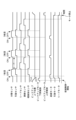
図6に、図4および図5の制御フローチャートで、異幅混載が設定されたときのタイミングチャートを示す。図6のタイミングチャートは、原稿トレイ30上に3枚の原稿からなる原稿束を載置した場合の搬送制御の信号および搬送モータの駆動の様子を表している。分離センサ12のON~OFFが、1枚の原稿搬送を表している。そして、時間の経過とともに、原稿は引抜後センサ13、リードセンサ15、排紙センサ16の順に検知される。
FIG. 6 shows a timing chart when mixed width loading is set in the control flowcharts of FIGS. 4 and 5. The timing chart in FIG. 6 shows the conveyance control signals and the drive of the conveyance motor when a document bundle consisting of three documents is placed on the
図6において、ピックアップ上下位置のチャートに示されるように、給紙ローラ1は、1枚目の原稿給紙から最終紙の給紙完了までの期間、当接位置を維持したままの給紙状態であることを示している。1枚目給紙前のS503で給紙ローラを下げ、「(1)上」位置(離間位置)から「(2)下」位置(当接位置)に給紙ローラ1を移動している。読取完了後、S525で給紙ローラ1を離間位置に上昇させている。これにより、混載原稿搬送時に、原稿トレイ上で給紙ローラを下げることで、原稿トレイ上で原稿を押さえることにより、原稿の斜行を予防できる。
As shown in the chart of the up and down positions of the pickup in FIG. 6, the
なお、図6の混載制御においては、後述する図8の定型サイズ原稿読取に比べて、CPU901からの給紙コマンドを待つ時間が長くなっている。これにより、分離後センサOFF~次の原稿の分離後センサONまでの時間t1が、図8に示す時間t3よりも長くなっている。
Note that in the mixed loading control shown in FIG. 6, the time required to wait for a paper feed command from the
図7に、図4および図5の制御フローチャートで、薄紙が設定されたときのタイミングチャートを示す。図7も図6と同様に、原稿トレイ30上に3枚の原稿からなる原稿束を載置した場合の搬送制御の信号および搬送モータの駆動の様子を表している。
FIG. 7 shows a timing chart when thin paper is set in the control flowcharts of FIGS. 4 and 5. Similarly to FIG. 6, FIG. 7 also shows the conveyance control signals and the drive of the conveyance motor when a document bundle consisting of three documents is placed on the
図7において、ピックアップ上下位置のチャートが、分離後センサ12がONした時に給紙ローラを離間位置に上昇し、分離後センサ12がOFFした時に給紙ローラ1を当接位置に下降させていることを示している。ピックアップ上下位置のチャートに示されるように、給紙ローラ1は、1枚目の原稿給紙前のS503で「(1)上」位置(離間位置)から「(2)下」位置(当接位置)に移動する。そして、分離後センサ12がONした後に、S510で「(3)上」位置(離間位置)に移動している。その後、分離後センサがOFFした後、給紙する際のS503で「(4)下」位置に移動している。読取完了後、S525で離間位置に移動する。これにより、薄紙時の原稿先端のしわを予防できる。
In FIG. 7, the chart of the top and bottom positions of the pickup shows that the
図8に、図4および図5の制御フローチャートで、普通紙かつ異幅混載が設定されなかった場合のタイミングチャートを示す。原稿トレイ30上に3枚の原稿からなる原稿束を載置した場合の搬送制御の信号および搬送モータの駆動の様子を表している。
FIG. 8 shows a timing chart when plain paper and mixed widths are not set in the control flowcharts of FIGS. 4 and 5. It shows the conveyance control signals and the drive of the conveyance motor when a document bundle consisting of three documents is placed on the
図8において、ピックアップ上下位置のチャートが、分離後センサON時に給紙ローラを上げ、分離後センサONから所定時間で給紙ローラ1を下げていることを示している。
In FIG. 8, the chart of the up and down positions of the pickup shows that the
1枚目給紙前のS503で給紙ローラを下げ、「(1)上」位置から「(2)下」位置に給紙ローラを移動し、分離後センサON後に、S510で給紙ローラを上げ「(3)上」位置に移動している。その後、引抜後センサONから所定時間経過後して、S520で給紙ローラを下げ、「(4)下」位置に移動している。読取完了後、S525で給紙ローラを上げている。 Before feeding the first sheet, lower the paper feed roller in S503, move the paper feed roller from the "(1) upper" position to the "(2) lower" position, and after separating and turn on the sensor, lower the paper feed roller in S510. It is moving to the "(3) up" position. Thereafter, after a predetermined time has elapsed since the post-pulling sensor was turned on, the paper feed roller is lowered in S520 and moved to the "(4) lower" position. After the reading is completed, the paper feed roller is raised in S525.
これにより、分離後センサOFF~次の原稿の分離後センサONまでの時間t3が、図6に示す時間t1や、図7に示す時間t2よりも短くなっている。この制御により、定型の原稿での生産性の向上させることができている。 As a result, the time t3 from the OFF of the sensor after separation to the ON of the sensor after separation of the next document is shorter than the time t1 shown in FIG. 6 and the time t2 shown in FIG. 7. This control makes it possible to improve the productivity of standard-sized originals.
このように、本実施例における画像読取装置は、原稿トレイ30に載置された複数枚の原稿を1枚ずつ給送する原稿給送モードとして、少なくとも2つの給送モードを選択的に実行可能である。1つ目の原稿給送モードは、原稿幅が同一の複数枚の原稿を給送する通常モードである。2つ目の原稿給送モードは、原稿幅が異なる複数枚の原稿を給送する異幅混載モードである。通常モードにおいては、原稿を1枚給送する度に給紙ローラ1を当接位置と離間位置との間で移動する。具体的には、原稿の先端が分離センサ12により検知された時に給紙ローラ1が離間位置に移動するので、給紙ローラと原稿面が擦れ、原稿に傷がつくのを抑制することができる。一方、異幅混載モードにおいて、給紙ローラ1の位置を、1枚目の原稿給紙から最終原稿の給紙までの期間、当接位置に保持する。これにより、給紙ローラ1の昇降に伴って原稿トレイ30上で原稿が回転するリスクを低減することができる。
As described above, the image reading device according to the present embodiment can selectively execute at least two feeding modes as the document feeding mode in which a plurality of documents placed on the
また本実施例においては、傷が生じやすい薄紙原稿を搬送する薄紙搬送モードの場合は、異幅混載モードであるか否かに関わらず、給紙ローラ1の昇降を繰り返す。これにより、薄紙原稿へのダメージを低減する。以上の制御により、異幅混載モードにおける回転リスクと薄紙原稿の搬送とを両立できる。
Further, in this embodiment, in the case of the thin paper transport mode in which thin paper originals that are likely to be scratched are transported, the
<その他の実施例>
実施例1では、異幅混載モードか通常モードかを操作表示部904を介して入力する例を説明した。しかしながら、上記の給送モードは、搬送路内で原稿の主走査方向幅を検知することで、異幅混載を操作部からの入力なく、原稿幅の検知結果に基づいて判定することも可能である。
<Other Examples>
In the first embodiment, an example has been described in which the different width mixed loading mode or the normal mode is inputted via the
図2のADF100の上部断面図において、原稿搬送路幅検知センサ14により搬送路を経由する原稿幅を検知し、原稿の主走査方向の原稿サイズ判別手段として用いることができる構成である。なお、画像処理部(A)810に原稿の主走査幅を検知することができる画像処理機構がある場合、画像から原稿幅を取得した際に異幅原稿があったことを判別することも可能である。
In the top cross-sectional view of the
図12は、CPU801が実行する搬送路内での異幅判定のフローチャートである。本フローチャートは、実施例1における図5 S511の引抜後センサONがYesとなった後に実行することで、原稿搬送路幅検知センサ14上に原稿があるタイミングで、原稿幅を検出できる。
FIG. 12 is a flowchart of the determination of different widths within the conveyance path, which is executed by the
CPU801は、原稿トレイの主走査長と原稿搬送路内の幅が異なるか否かを判定する(S1201)。
The
CPU801は、原稿トレイ上幅検知センサ809の幅情報と、原稿搬送路幅検知センサ14のON/OFFの組み合わせが異なる場合、異幅であると判定する。
If the width information of the document tray upper width detection sensor 809 and the ON/OFF combination of the document conveyance path
例えば、図11(A)のように1枚目にB5サイズ、2枚目にA4サイズの原稿を原稿トレイ上に置く。このとき、原稿トレイ上幅検知センサ809の幅情報がA4として検知しているとき、実際にB5サイズの原稿が搬送される場合には、主走査幅検知センサ14のどれか一つのセンサがOFFすることになる(図13)。図13は、図2の上面透視図であり、原稿トレイ上にA4が載置され、搬送中のB5サイズ原稿を搬送路内で幅検知したタイミングでの原稿位置を表す。
For example, as shown in FIG. 11(A), the first B5 size document and the second A4 size document are placed on the document tray. At this time, when the width information of the document tray upper width detection sensor 809 is detected as A4, if a B5 size document is actually conveyed, one of the main scanning
B5サイズを搬送する場合、原稿搬送路幅検知センサ14a、14b、14cはON(黒塗りで示したセンサ)であり、原稿搬送路幅検知センサ14dは、OFFであり、トレイ上の幅と異なることが判別できる。
When conveying a B5 size document, the document conveyance path
すなわち、原稿トレイ上幅検知センサ809の幅情報と、原稿搬送路幅検知センサ14の検知の差が発生することを確認することで、主走査幅の異なる原稿が混在していたと判断することが可能である。
That is, by confirming that there is a difference between the width information of the document tray upper width detection sensor 809 and the detection of the document conveyance path
CPU801は、原稿トレイの主走査長と原稿搬送路内の幅が異なる場合(S1201 Yes)、給紙ローラ制御設定を下降設定にする(S1202)。
If the main scanning length of the document tray and the width within the document conveyance path are different (S1201 Yes), the
給紙ローラ制御設定は、RAM803に持つ変数であり、実施例1の図5の給紙ローラの上昇下降制御時に参照することにより、給紙ローラを下げたまま給紙することが可能となる。
The paper feed roller control setting is a variable held in the
第2の実施例によれば、操作表示部により異幅混載を指定せずに、幅方向の長さが異なる複数枚の原稿であることを判定することができる。 According to the second embodiment, it is possible to determine that there are a plurality of originals having different lengths in the width direction without specifying mixed widths of different widths on the operation display unit.
以上より、本実施例における画像読取装置は、原稿トレイ30に載置された複数枚の原稿を1枚ずつ給送する原稿給送モードとして、少なくとも2つの給送モードを選択的に実行可能である。1つ目の原稿給送モードは、原稿幅が同一の複数枚の原稿を給送する通常モードである。2つ目の原稿給送モードは、原稿幅が異なる複数枚の原稿を給送する異幅混載モードである。通常モードにおいては、原稿を1枚給送する度に給紙ローラ1を当接位置と離間位置との間で移動する。具体的には、原稿の先端が分離センサ12により検知された時に給紙ローラ1が離間位置に移動するので、給紙ローラと原稿面が擦れ、原稿に傷がつくのを抑制することができる。一方、異幅混載モードにおいて、給紙ローラ1の位置を、1枚目の原稿給紙から最終原稿の給紙までの期間、当接位置に保持する。これにより、給紙ローラ1の昇降に伴って原稿トレイ30上で原稿が回転するリスクを低減することができる。
As described above, the image reading device according to the present embodiment can selectively execute at least two feeding modes as the document feeding mode in which multiple sheets of originals placed on the
また本実施例においては、傷が生じやすい薄紙原稿を搬送する薄紙搬送モードの場合は、異幅混載モードであるか否かに関わらず、給紙ローラ1の昇降を繰り返す。これにより、薄紙原稿へのダメージを低減する。以上の制御により、異幅混載モードにおける回転リスクと薄紙原稿の搬送とを両立できる。
Further, in this embodiment, in the case of the thin paper transport mode in which thin paper originals that are likely to be scratched are transported, the
また、本発明は、以下の処理を実行することによっても実現される。即ち、上述した実施形態の機能を実現するソフトウェア(プログラム)を、ネットワーク又は各種記憶媒体を介してシステム或いは装置に供給し、そのシステム或いは装置のコンピュータ(またはCPUやMPU等)がプログラムを読み出して実行する処理である。 Further, the present invention can also be realized by executing the following processing. That is, the software (program) that realizes the functions of the embodiments described above is supplied to a system or device via a network or various storage media, and the computer (or CPU, MPU, etc.) of the system or device reads the program. This is the process to be executed.
1 給紙ローラ
2 分離上ローラ
3 分離下ローラ
4 引抜1ローラ
5 引抜2ローラ
6 読み取り上流リードローラ
7 ガイド板上流ローラ
8 ガイド板下流ローラ
9 裏面読み取り搬送ローラ
10 排紙ローラ
11 原稿有無検知センサ
12 分離センサ
13 引抜センサ
14 主走査幅検知センサ
15 リードセンサ
16 排紙センサ
17 トレイ上原稿長センサ1
18 トレイ上原稿長センサ2
30 原稿トレイ
31 原稿ガイド板
32 排紙トレイ
100 自動原稿給紙搬送装置部(ADF)
101 裏面ガラス対向部材
102 裏面光学スキャナユニット
103 裏面LED
104 裏面ミラー
105 裏面画像読取センサ
110 裏面シェーディング白板
200 画像読取部
201 表面流し読みガラス
202 表面光学スキャナユニット
203 表面LED
204 表面ミラー
205 表面画像読取センサ
209 原稿載置ガラス
210 表面シェーディング白板
211 表面ガラス対向部材
301 コマンド送信部
302 画像通信部
300 画像処理コントローラ
310 原稿読取/ADFコントローラ
801 CPU
802 ROM
803 RAM
804 光学モータ
805 分離モータ
806 引抜モータ
807 リードモータ
808 ピックアップモータ
809 トレイ上幅検知センサ
810 画像処理部
901 CPU
902 ROM
903 RAM
904 操作表示部
905 画像処理部
906 画像メモリ
1000 画像読取装置
1
18 Tray
30 Document tray 31
101 Back
104
204
802 ROM
803 RAM
804
902 ROM
903 RAM
904
Claims (7)
前記原稿トレイに載置された原稿を給送方向へ給送する給送ローラと、
前記給送方向において前記給送ローラの下流に配置され、給送されるシートを1枚ずつ分離する分離手段と、
前記分離手段により分離された原稿の画像を読み取る画像読取部と、
前記給送ローラを、前記原稿トレイに載置された原稿の上面に当接する当接位置と、前記当接位置よりも上方であり且つ前記原稿から離間した離間位置との間で昇降させる昇降手段と、
前記原稿トレイに載置された原稿の種類として、第1種類の原稿及び前記第1種類よりも坪量の小さい第2種類の原稿を選択するための選択手段と、
原稿給送モードとして、前記給送方向に直交する幅方向の長さが同一である複数の原稿を給送する第1モードと、前記幅方向の長さが異なる複数の原稿を給送する第2モードと、を選択的に実行可能な制御手段であって、前記第1モードにおいて複数の原稿を給送する際に、原稿を1枚給送する度に前記給送ローラを前記当接位置と前記離間位置とに移動させ、前記第2モードにおいて複数の原稿を給送する際に、1枚目の原稿の給送開始から最終原稿の給送が完了するまでの期間、前記給送ローラを前記当接位置に保持するように前記昇降手段を制御する制御手段と、
を有し、
前記制御手段は、前記選択手段により前記第2種類の原稿が選択された場合、前記第2モードであっても、原稿を1枚給送する度に前記給送ローラを前記当接位置と前記離間位置とに移動させることを特徴とする画像読取装置。 a document tray on which documents are placed;
a feeding roller that feeds a document placed on the document tray in a feeding direction;
Separating means disposed downstream of the feeding roller in the feeding direction and separating fed sheets one by one;
an image reading unit that reads an image of the document separated by the separating means;
Lifting means for raising and lowering the feeding roller between a contact position where it contacts the upper surface of a document placed on the document tray and a separate position which is above the contact position and is spaced apart from the document. and,
Selection means for selecting a first type of original and a second type of original having a smaller basis weight than the first type as types of originals placed on the original tray;
The document feeding modes include a first mode in which a plurality of documents having the same length in the width direction perpendicular to the feeding direction are fed, and a first mode in which a plurality of documents having different lengths in the width direction are fed. 2 modes, wherein when feeding a plurality of originals in the first mode, the feeding roller is moved to the contact position each time one original is fed. and the separated position, and when feeding a plurality of originals in the second mode, the feeding roller control means for controlling the elevating means to maintain the elevating means in the abutting position;
has
When the second type of original is selected by the selection means, the control means moves the feeding roller between the contact position and the contact position each time one original is fed , even in the second mode. An image reading device characterized in that the image reading device is moved to a separated position.
前記原稿トレイに載置された原稿を給送方向へ給送する給送ローラと、
前記給送方向において前記給送ローラの下流に配置され、給送されるシートを1枚ずつ分離する分離手段と、
前記分離手段により分離された原稿の画像を読み取る画像読取部と、
前記給送ローラを、前記原稿トレイに載置された原稿の上面に当接する当接位置と、前記当接位置よりも上方であり且つ前記原稿から離間した離間位置との間で昇降させる昇降手段と、
前記原稿トレイに載置された原稿の種類として、第1種類の原稿及び前記第1種類よりも薄い第2種類の原稿を選択するための選択手段と、
原稿給送モードとして、前記給送方向に直交する幅方向の長さが同一である複数の原稿を給送する第1モードと、前記幅方向の長さが異なる複数の原稿を給送する第2モードと、を選択的に実行可能な制御手段であって、前記第1モードにおいて複数の原稿を給送する際に、原稿を1枚給送する度に前記給送ローラを前記当接位置と前記離間位置とに移動させ、前記第2モードにおいて複数の原稿を給送する際に、1枚目の原稿の給送開始から最終原稿の給送が完了するまでの期間、前記給送ローラを前記当接位置に保持するように前記昇降手段を制御する制御手段と、
を有し、
前記制御手段は、前記選択手段により前記第2種類の原稿が選択された場合、前記第2モードであっても、原稿を1枚給送する度に前記給送ローラを前記当接位置と前記離間位置とに移動させることを特徴とする画像読取装置。 a document tray on which documents are placed;
a feeding roller that feeds a document placed on the document tray in a feeding direction;
Separating means disposed downstream of the feeding roller in the feeding direction and separating fed sheets one by one;
an image reading unit that reads an image of the document separated by the separating means;
Lifting means for raising and lowering the feeding roller between a contact position where it contacts the upper surface of a document placed on the document tray and a separate position which is above the contact position and is spaced apart from the document. and,
selection means for selecting a first type of original and a second type of original that is thinner than the first type as types of originals placed on the original tray;
The document feeding modes include a first mode in which a plurality of documents having the same length in the width direction perpendicular to the feeding direction are fed, and a first mode in which a plurality of documents having different lengths in the width direction are fed. 2 modes, wherein when feeding a plurality of originals in the first mode, the feeding roller is moved to the contact position each time one original is fed. and the separated position, and when feeding a plurality of originals in the second mode, the feeding roller control means for controlling the elevating means to maintain the elevating means in the abutting position;
has
When the second type of original is selected by the selection means, the control means moves the feeding roller between the contact position and the contact position each time one original is fed , even in the second mode. An image reading device characterized in that the image reading device is moved to a separated position.
前記原稿給送モードは前記操作部を介して設定されることを特徴とする請求項1又は2に記載の画像読取装置。 It has an operation unit that accepts user instructions,
3. The image reading apparatus according to claim 1, wherein the document feeding mode is set via the operation unit.
前記第1モードにおいて、前記制御手段は、前記分離センサにより原稿の先端が検知されたことに基づいて前記給送ローラを前記離間位置に上昇させることを特徴とする請求項1乃至4の何れか1項に記載の画像読取装置。 further comprising a separation sensor that detects a document downstream of the separation means in the feeding direction;
5. In the first mode, the control means raises the feeding roller to the separated position based on the detection of the leading edge of the document by the separation sensor. The image reading device according to item 1.
前記給送方向において前記引抜ローラの下流に配置された、原稿を検知する引抜後センサと、
を有し、
前記第1モードにおいて、前記制御手段は、前記引抜後センサにより原稿の先端が検知されてから所定時間が経過した場合に前記給送ローラを前記当接位置に下降させることを特徴とする請求項5に記載の画像読取装置。 a pull-out roller for conveying the document, disposed downstream of the separating means in the feeding direction;
a post-pulling sensor for detecting a document, disposed downstream of the pulling roller in the feeding direction;
has
2. In the first mode, the control means lowers the feeding roller to the contact position when a predetermined time has elapsed since the leading edge of the document was detected by the post-pulling sensor. 5. The image reading device according to 5.
Priority Applications (1)
| Application Number | Priority Date | Filing Date | Title |
|---|---|---|---|
| JP2019208333A JP7443028B2 (en) | 2019-11-18 | 2019-11-18 | Image reading device |
Applications Claiming Priority (1)
| Application Number | Priority Date | Filing Date | Title |
|---|---|---|---|
| JP2019208333A JP7443028B2 (en) | 2019-11-18 | 2019-11-18 | Image reading device |
Publications (3)
| Publication Number | Publication Date |
|---|---|
| JP2021080061A JP2021080061A (en) | 2021-05-27 |
| JP2021080061A5 JP2021080061A5 (en) | 2022-11-16 |
| JP7443028B2 true JP7443028B2 (en) | 2024-03-05 |
Family
ID=75964074
Family Applications (1)
| Application Number | Title | Priority Date | Filing Date |
|---|---|---|---|
| JP2019208333A Active JP7443028B2 (en) | 2019-11-18 | 2019-11-18 | Image reading device |
Country Status (1)
| Country | Link |
|---|---|
| JP (1) | JP7443028B2 (en) |
Citations (4)
| Publication number | Priority date | Publication date | Assignee | Title |
|---|---|---|---|---|
| JP2010202358A (en) | 2009-03-04 | 2010-09-16 | Ricoh Co Ltd | Document feeding device and image forming device |
| JP2012254856A (en) | 2011-06-08 | 2012-12-27 | Ricoh Co Ltd | Sheet conveyance device, and image reading device and image forming apparatus |
| JP2018024521A (en) | 2016-08-12 | 2018-02-15 | キヤノン株式会社 | Sheet feeding device and image formation apparatus |
| JP2018058666A (en) | 2016-10-04 | 2018-04-12 | 富士ゼロックス株式会社 | Document conveying device, image reading device and image forming device |
-
2019
- 2019-11-18 JP JP2019208333A patent/JP7443028B2/en active Active
Patent Citations (4)
| Publication number | Priority date | Publication date | Assignee | Title |
|---|---|---|---|---|
| JP2010202358A (en) | 2009-03-04 | 2010-09-16 | Ricoh Co Ltd | Document feeding device and image forming device |
| JP2012254856A (en) | 2011-06-08 | 2012-12-27 | Ricoh Co Ltd | Sheet conveyance device, and image reading device and image forming apparatus |
| JP2018024521A (en) | 2016-08-12 | 2018-02-15 | キヤノン株式会社 | Sheet feeding device and image formation apparatus |
| JP2018058666A (en) | 2016-10-04 | 2018-04-12 | 富士ゼロックス株式会社 | Document conveying device, image reading device and image forming device |
Also Published As
| Publication number | Publication date |
|---|---|
| JP2021080061A (en) | 2021-05-27 |
Similar Documents
| Publication | Publication Date | Title |
|---|---|---|
| JP5321146B2 (en) | Document feeder and image forming apparatus | |
| JP5341493B2 (en) | Sheet transport device | |
| JP4974754B2 (en) | Image reading device | |
| JP4382561B2 (en) | Automatic document feeder | |
| JP6265593B2 (en) | Document reading apparatus and document reading method | |
| US8128081B2 (en) | Document feeding apparatus | |
| JP2019068218A (en) | Image reading device and control method for the same | |
| US11546482B2 (en) | Document reading apparatus, control method thereof, and storage medium | |
| US10136001B2 (en) | Image forming apparatus, method for controlling image forming apparatus, and storage medium | |
| JP2014150322A5 (en) | ||
| JP2024026841A (en) | Sheet feeding device, image reading device, and image forming device | |
| JP2009044449A (en) | Automatic document feeder, and image forming apparatus | |
| JP6361620B2 (en) | Reading apparatus and image forming apparatus provided with the same | |
| US9376276B2 (en) | Sheet feeding apparatus and image forming apparatus | |
| JP6676298B2 (en) | Image reading device and image forming device | |
| JP7443028B2 (en) | Image reading device | |
| JP2007311890A (en) | Image reading apparatus, program, and recording medium | |
| JP6452398B2 (en) | Image reading device | |
| JP2022021871A (en) | Document reading device and method for controlling the same, and program | |
| JP2021038090A (en) | Image reader | |
| JP7379049B2 (en) | Sheet feeding device, image reading device, and image forming device | |
| JP2005263396A (en) | Automatic document feeder and image forming device | |
| JP2017024847A (en) | Image reading apparatus and image forming apparatus | |
| JP7247029B2 (en) | Paper transport device | |
| JP2020061627A (en) | Image reading device, image reading method |
Legal Events
| Date | Code | Title | Description |
|---|---|---|---|
| A521 | Request for written amendment filed |
Free format text: JAPANESE INTERMEDIATE CODE: A523 Effective date: 20221108 |
|
| A621 | Written request for application examination |
Free format text: JAPANESE INTERMEDIATE CODE: A621 Effective date: 20221108 |
|
| A977 | Report on retrieval |
Free format text: JAPANESE INTERMEDIATE CODE: A971007 Effective date: 20230809 |
|
| A131 | Notification of reasons for refusal |
Free format text: JAPANESE INTERMEDIATE CODE: A131 Effective date: 20230822 |
|
| A521 | Request for written amendment filed |
Free format text: JAPANESE INTERMEDIATE CODE: A523 Effective date: 20231020 |
|
| RD01 | Notification of change of attorney |
Free format text: JAPANESE INTERMEDIATE CODE: A7421 Effective date: 20231213 |
|
| TRDD | Decision of grant or rejection written | ||
| A01 | Written decision to grant a patent or to grant a registration (utility model) |
Free format text: JAPANESE INTERMEDIATE CODE: A01 Effective date: 20240123 |
|
| A61 | First payment of annual fees (during grant procedure) |
Free format text: JAPANESE INTERMEDIATE CODE: A61 Effective date: 20240221 |
|
| R151 | Written notification of patent or utility model registration |
Ref document number: 7443028 Country of ref document: JP Free format text: JAPANESE INTERMEDIATE CODE: R151 |