JP5341493B2 - Sheet transport device - Google Patents
Sheet transport device Download PDFInfo
- Publication number
- JP5341493B2 JP5341493B2 JP2008321631A JP2008321631A JP5341493B2 JP 5341493 B2 JP5341493 B2 JP 5341493B2 JP 2008321631 A JP2008321631 A JP 2008321631A JP 2008321631 A JP2008321631 A JP 2008321631A JP 5341493 B2 JP5341493 B2 JP 5341493B2
- Authority
- JP
- Japan
- Prior art keywords
- document
- mode
- length
- sensor
- separation
- Prior art date
- Legal status (The legal status is an assumption and is not a legal conclusion. Google has not performed a legal analysis and makes no representation as to the accuracy of the status listed.)
- Active
Links
Images


Classifications
-
- B—PERFORMING OPERATIONS; TRANSPORTING
- B65—CONVEYING; PACKING; STORING; HANDLING THIN OR FILAMENTARY MATERIAL
- B65H—HANDLING THIN OR FILAMENTARY MATERIAL, e.g. SHEETS, WEBS, CABLES
- B65H3/00—Separating articles from piles
- B65H3/02—Separating articles from piles using friction forces between articles and separator
- B65H3/06—Rollers or like rotary separators
- B65H3/0684—Rollers or like rotary separators on moving support, e.g. pivoting, for bringing the roller or like rotary separator into contact with the pile
-
- B—PERFORMING OPERATIONS; TRANSPORTING
- B65—CONVEYING; PACKING; STORING; HANDLING THIN OR FILAMENTARY MATERIAL
- B65H—HANDLING THIN OR FILAMENTARY MATERIAL, e.g. SHEETS, WEBS, CABLES
- B65H5/00—Feeding articles separated from piles; Feeding articles to machines
- B65H5/06—Feeding articles separated from piles; Feeding articles to machines by rollers or balls, e.g. between rollers
- B65H5/062—Feeding articles separated from piles; Feeding articles to machines by rollers or balls, e.g. between rollers between rollers or balls
-
- B—PERFORMING OPERATIONS; TRANSPORTING
- B65—CONVEYING; PACKING; STORING; HANDLING THIN OR FILAMENTARY MATERIAL
- B65H—HANDLING THIN OR FILAMENTARY MATERIAL, e.g. SHEETS, WEBS, CABLES
- B65H7/00—Controlling article feeding, separating, pile-advancing, or associated apparatus, to take account of incorrect feeding, absence of articles, or presence of faulty articles
- B65H7/18—Modifying or stopping actuation of separators
-
- B—PERFORMING OPERATIONS; TRANSPORTING
- B65—CONVEYING; PACKING; STORING; HANDLING THIN OR FILAMENTARY MATERIAL
- B65H—HANDLING THIN OR FILAMENTARY MATERIAL, e.g. SHEETS, WEBS, CABLES
- B65H2404/00—Parts for transporting or guiding the handled material
- B65H2404/60—Other elements in face contact with handled material
- B65H2404/61—Longitudinally-extending strips, tubes, plates, or wires
- B65H2404/611—Longitudinally-extending strips, tubes, plates, or wires arranged to form a channel
- B65H2404/6111—Longitudinally-extending strips, tubes, plates, or wires arranged to form a channel and shaped for curvilinear transport path
-
- B—PERFORMING OPERATIONS; TRANSPORTING
- B65—CONVEYING; PACKING; STORING; HANDLING THIN OR FILAMENTARY MATERIAL
- B65H—HANDLING THIN OR FILAMENTARY MATERIAL, e.g. SHEETS, WEBS, CABLES
- B65H2511/00—Dimensions; Position; Numbers; Identification; Occurrences
- B65H2511/10—Size; Dimensions
- B65H2511/11—Length
-
- B—PERFORMING OPERATIONS; TRANSPORTING
- B65—CONVEYING; PACKING; STORING; HANDLING THIN OR FILAMENTARY MATERIAL
- B65H—HANDLING THIN OR FILAMENTARY MATERIAL, e.g. SHEETS, WEBS, CABLES
- B65H2511/00—Dimensions; Position; Numbers; Identification; Occurrences
- B65H2511/20—Location in space
-
- B—PERFORMING OPERATIONS; TRANSPORTING
- B65—CONVEYING; PACKING; STORING; HANDLING THIN OR FILAMENTARY MATERIAL
- B65H—HANDLING THIN OR FILAMENTARY MATERIAL, e.g. SHEETS, WEBS, CABLES
- B65H2511/00—Dimensions; Position; Numbers; Identification; Occurrences
- B65H2511/40—Identification
- B65H2511/414—Identification of mode of operation
-
- B—PERFORMING OPERATIONS; TRANSPORTING
- B65—CONVEYING; PACKING; STORING; HANDLING THIN OR FILAMENTARY MATERIAL
- B65H—HANDLING THIN OR FILAMENTARY MATERIAL, e.g. SHEETS, WEBS, CABLES
- B65H2511/00—Dimensions; Position; Numbers; Identification; Occurrences
- B65H2511/50—Occurence
- B65H2511/51—Presence
- B65H2511/514—Particular portion of element
-
- B—PERFORMING OPERATIONS; TRANSPORTING
- B65—CONVEYING; PACKING; STORING; HANDLING THIN OR FILAMENTARY MATERIAL
- B65H—HANDLING THIN OR FILAMENTARY MATERIAL, e.g. SHEETS, WEBS, CABLES
- B65H2513/00—Dynamic entities; Timing aspects
- B65H2513/50—Timing
-
- B—PERFORMING OPERATIONS; TRANSPORTING
- B65—CONVEYING; PACKING; STORING; HANDLING THIN OR FILAMENTARY MATERIAL
- B65H—HANDLING THIN OR FILAMENTARY MATERIAL, e.g. SHEETS, WEBS, CABLES
- B65H2513/00—Dynamic entities; Timing aspects
- B65H2513/50—Timing
- B65H2513/512—Starting; Stopping
-
- B—PERFORMING OPERATIONS; TRANSPORTING
- B65—CONVEYING; PACKING; STORING; HANDLING THIN OR FILAMENTARY MATERIAL
- B65H—HANDLING THIN OR FILAMENTARY MATERIAL, e.g. SHEETS, WEBS, CABLES
- B65H2551/00—Means for control to be used by operator; User interfaces
- B65H2551/10—Command input means
- B65H2551/14—Switches; Selectors
-
- B—PERFORMING OPERATIONS; TRANSPORTING
- B65—CONVEYING; PACKING; STORING; HANDLING THIN OR FILAMENTARY MATERIAL
- B65H—HANDLING THIN OR FILAMENTARY MATERIAL, e.g. SHEETS, WEBS, CABLES
- B65H2701/00—Handled material; Storage means
- B65H2701/10—Handled articles or webs
- B65H2701/13—Parts concerned of the handled material
- B65H2701/131—Edges
- B65H2701/1313—Edges trailing edge
-
- B—PERFORMING OPERATIONS; TRANSPORTING
- B65—CONVEYING; PACKING; STORING; HANDLING THIN OR FILAMENTARY MATERIAL
- B65H—HANDLING THIN OR FILAMENTARY MATERIAL, e.g. SHEETS, WEBS, CABLES
- B65H2801/00—Application field
- B65H2801/39—Scanning
Description
本発明は、シート搬送装置に関するものである。 The present invention relates to a sheet conveying apparatus.
近年、オフィスで使用される帳票類のコピーや電子データ化するニーズが高くなってきている。それにともなって、さまざまな種類の原稿束を、高速に分離・搬送して読み取る自動原稿搬送装置が求められている。自動原稿搬送装置の給紙装置には、積載されたシートを1枚ずつ分離する分離部と、分離部へシートを給送する給送部とに大きく分けられ、それぞれ多様な方式がある。分離方式には、分離パッドを用いた分離方式や、近年では、厚紙等の原稿を搬送するために搬送力の高いリタード分離方式も採用されている。 In recent years, there has been a growing need for copying forms and electronic data used in offices. Accordingly, there is a need for an automatic document feeder that reads and bundles various types of document bundles at high speed. A paper feeder of an automatic document feeder is roughly divided into a separation unit that separates stacked sheets one by one and a feeding unit that feeds sheets to the separation unit, and there are various methods. As a separation method, a separation method using a separation pad and, in recent years, a retard separation method having a high conveying force for conveying an original such as cardboard is also employed.
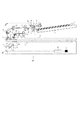
図8は、一般的なリタード分離方式の給送装置の駆動及び制御信号の伝達経路の概略を示したものである。図中、太線は駆動信号の伝達経路を示す。501は1枚或いは複数枚の原稿を積載する原稿トレイである。原稿トレイ501の上方には、揺動支点を有する移動手段としての揺動アーム510が設けられる。該アーム510の端部には原稿トレイ501に支持された最上位のシートに当接してシートを送り出す方向に回転するシート給送手段としてのピックアップローラ502が設けられている。ピックアップローラ502はピックアップモータ539の駆動によって揺動アーム510が揺動し、原稿トレイ501上のシートに当接してシートを送り出す圧接位置と、シートから離間した待避位置とに変位可能である。ピックアップローラ502のシート送り出し方向の下流側には送り出されたシートをさらに下流へと搬送するフィードローラ504とリタードローラ505からなる分離手段としての分離ローラ対503が設けられている。リタードローラ505は、フィードローラ504に圧接し、シートを原稿トレイ501側に戻す方向に回転する駆動が伝達される。ピックアップローラ502から送り出されたシートは分離ローラ対503のニップ部に挟持されて搬送されることでシートが1枚ずつに分離される。なお、これら全てのローラは1つのモータ537からの駆動が伝達されて回転するよう構成されている。リタードローラ505にはトルクリミッタ(不図示)を介してシート搬送方向とは逆方向の回転となるように駆動が伝達されている。一方、リタードローラ505に圧接しているフィードローラ504はシート搬送方向へ回転することでリタードローラ505にはシート搬送方向へのトルクが与えられる。トルクリミッタの設定トルクはリタードローラ505がフィードローラ504から付与されるトルクよりも小さい値に設定されているため、リタードローラ505はフィードローラ504の回転を受けてシート搬送方向に従動回転する。ピックアップローラによる給送動作により2枚以上のシートが分離ローラ対503に送られてくることがある(この状態を重送と称す)。この場合、ローラとシートとの摩擦係数よりもシート間の摩擦係数が小さいため、トルクリミッタの作用によりシート搬送方向と逆方向の駆動が伝達されたリタードローラ505はシート搬送方向と逆方向に回転する。その結果、最上位のシート以外のシートは原稿トレイ501の方向に戻される。これによりシートは1枚ずつ画像形成手段としての画像形成部へ搬送される。
FIG. 8 shows an outline of a drive path and a control signal transmission path of a general retard separation type feeding apparatus. In the drawing, a bold line indicates a transmission path of a drive signal.
通常、ピックアップローラ502は、シートの送り出し開始から所定のタイミングでシート面から離間する。センサ511がシート後端を検知後、次の給紙動作のためにピックアップローラ502が原稿に当接する。単位時間当たりの搬送枚数を向上させる方法として以下の方法が考えられている。即ち、原稿の長さとピックアップローラ502の当接に要する時間とに基づいて、原稿後端が分離ローラ対503を通過するタイミングを予測して、ピックアップローラ502を原稿に当接させる方法が提案されている(特許文献1参照)。
従来より、自動原稿搬送装置の機能として、複数の原稿を1枚毎にサイズ検知して、検知したサイズに応じた処理を行う、所謂、混載モードを有した装置が存在する。この混載モードを指定しない場合は、原稿毎にサイズに応じた処理はされず、全ての原稿サイズを同一のサイズで扱う。例えば、1枚目の原稿で検知したサイズや、ユーザによって指定されたサイズで全ての原稿を扱う。 2. Description of the Related Art Conventionally, as an automatic document feeder, there is an apparatus having a so-called mixed loading mode in which a size of a plurality of documents is detected for each sheet, and processing corresponding to the detected size is performed. When this mixed loading mode is not designated, the processing corresponding to the size is not performed for each document, and all document sizes are handled with the same size. For example, all the originals are handled with the size detected by the first original or the size specified by the user.
原稿読み取りの生産性(単位時間あたりの読取枚数)を向上させるためには、原稿の分離搬送後、できるだけ早いタイミングでピックアップローラ502を降下させ、次のシート搬送に備える必要がある。そこで、特許文献1に記載の方法では、混載モードを指定しない場合には、シート後端がセンサ511を通過するより前に、ピックアップローラ502を降下させることで、生産性を向上させることが可能である。
In order to improve manuscript reading productivity (number of readings per unit time), it is necessary to lower the
しかし、混載モードを指定していないにも拘わらず、シート束の中に異なる長さのシートが混じっていると、ピックアップローラ502がシート束に当接する位置が想定した位置とずれてしまう。
However, when sheets of different lengths are mixed in the sheet bundle even though the mixed loading mode is not designated, the position where the
例えば、図9は、1枚目のシートがA4サイズでN−1枚目がA3サイズである場合、N−1枚目のシートの後端が分離ローラ対503を通過したと想定したタイミングでピックアップローラ502を降下させた後のシートの挙動を示した図である。このとき、リタードローラ505の耐久性低下を防ぐためにために、N−1枚目のシート(A4と想定)の後端が分離ローラ対503を抜けると想定される直前のタイミングでモータ537を停止させる。そのため、図9(a)に示すようにN−1枚目のシートはモータ538で駆動されるローラ506によって搬送されており、分離ローラ対503は搬送されるシートに従動してシート搬送方向に回転する。このとき、ピックアップローラ502は回転が停止した状態でN−1枚目のシートに当接しており、その自重によってN−1枚目とN枚目のシートに摩擦力が生じる。その結果、図9(b)のように、N枚目のシートが引き摺られて分離ローラ対503を通り抜けていくため、重送が発生してしまう可能性がある。
For example, FIG. 9 shows timing when it is assumed that the trailing edge of the (N−1) th sheet has passed the
また、図10は、1枚目のシートがA3サイズでN−1枚目のシートがA4サイズであった場合の、N−1枚目のシートの後端の挙動を示す図である。このとき、図10(a)に示すように、N−1枚目のシートとN枚目シートとの摩擦係数が高いとN枚目のシートが引き摺られて分離ローラ対503付近に接近する。このとき、図10(b)のようにN枚目のシートの先端に折れやカールが生じている場合、図10(c)のようにフィードローラ504に引き込まれてしまい、N枚目とN−1枚目のシートの間隔が狭くなり、結果としてジャムになってしまう可能性がある。
FIG. 10 is a diagram illustrating the behavior of the trailing edge of the (N−1) th sheet when the first sheet is A3 size and the (N−1) th sheet is A4 size. At this time, as shown in FIG. 10A, when the friction coefficient between the (N−1) th sheet and the Nth sheet is high, the Nth sheet is dragged and approaches the vicinity of the
そのため、上記構成のリタード分離方式の自動原稿搬送装置において、原稿読み取りの生産性を上げるために特許文献1の方法を用いた場合、シート束の中に異なる長さのシートが混じっていると、重送やジャムが発生してしまうことがあった。
Therefore, in the retard separation type automatic document feeder having the above-described configuration, when the method of
上記の課題を解決するために、本発明の原稿給送装置は、複数枚の原稿を積載する原稿トレイと、前記原稿トレイに積載された原稿上に当接して原稿を送り出し、送り出し後に前記原稿トレイ上の原稿から離間するピックアップローラと、重送された原稿を分離可能な分離手段であって、前記ピックアップローラにより送り出された原稿をさらに搬送する分離手段と、原稿の長さを検出する長さ検出手段と、前記原稿トレイよりも下流側に設けられ、前記送り出された原稿の後端を検出する原稿センサと、前記原稿トレイからの原稿の送り出しを制御する制御手段であって、前記原稿センサが原稿の後端を検出したことに応じて決定されるタイミングで、前記送り出された原稿の次の原稿に前記ピックアップローラを当接させる第1モードと、3枚目以降の各原稿については、前記原稿センサが直前に送り出された原稿の後端を検出するよりも前のタイミングであって且つ前記長さ検出手段により検出された1枚目の原稿の長さに応じて決定されるタイミングで前記原稿トレイ上の原稿に前記ピックアップローラを当接させる第2モードを選択可能な制御手段と、を有し、前記制御手段は、前記第2モードで原稿の送り出しを制御している場合に、前記1枚目の原稿の長さよりも短い原稿の長さが検出されると、前記第2モードから前記第1モードへ切り替えることを特徴とする。 In order to solve the above problem, the document feeding apparatus of the present invention includes a document tray for stacking a plurality of originals, feeding the document to abut on the loaded document to the document tray, the later delivery a pickup roller to separate from the document on the document tray, a separable separating means multi-fed document separating means for further conveying the document fed by the pickup roller, detecting the length of the document the length detecting means, than said document tray is provided on the downstream side, and a document sensor for detecting the rear end of the fed original document, and a control means for controlling the feeding of the document from the document tray, the at the timing when the document sensor is determined according to the detection of the rear end of the document, a first mode in which contact the pickup roller to the next document of the fed original document For each of the three subsequent original sheets, the document sensor is first document detected by and said length detection means a previous timing than detecting the rear end of the document fed just before Control means capable of selecting a second mode in which the pickup roller is brought into contact with the document on the document tray at a timing determined according to the length, and the control means is configured to select the document in the second mode. If that controls the delivery of, the length of the shorter document than the length of the first document is discovered, characterized in that Ru switching from said second mode to said first mode.
本発明によれば、同一サイズ原稿搬送モードで原稿の給紙を制御する場合に、シート束の原稿が全て同じサイズであった場合には高生産性を維持することができ、シート束の中に異なる長さのシートが混じっていた場合でも重送やジャムの低減することができる。 According to the present invention, when document feeding is controlled in the same size document transport mode, high productivity can be maintained when all the documents in a sheet bundle are the same size. Even when sheets of different lengths are mixed, double feeding and jamming can be reduced.
以下、本発明の一実施形態を図面に基づいて説明する。 Hereinafter, an embodiment of the present invention will be described with reference to the drawings.
<画像読取装置>
本実施形態における図1は原稿給送装置を有した画像読取装置の断面図である。
<Image reading device>
FIG. 1 in this embodiment is a cross-sectional view of an image reading apparatus having a document feeding device.
原稿の搬送中に原稿画像を読み取る「原稿流し読み」時の動作について図1を参照しながら説明する。画像読取部100は、図1に示すように、1枚或いは複数枚の原稿で構成される原稿束を載置する昇降可能な原稿トレイ1と、原稿束の最上面の原稿上に降下して原稿を機内に送り出し、送り出し後に上昇するピックアップローラ2とを有する。原稿の搬送開始前に、ピックアップローラ2を降下させ、リフターモータ(図示せず)を駆動して原稿トレイ1を上昇させる。原稿束の最上面の原稿が給送位置に到達すると、原稿束の最上面に当接しているピックアップローラ2に連動して回転する紙面検知フラグ9が紙面検知センサ10を遮断してオンを出力し、原稿トレイ1の上昇を停止させる。
The operation at the time of “original flow scanning” for reading an original image during conveyance of the original will be described with reference to FIG. As shown in FIG. 1, the
その後ピックアップローラ2によって給送された原稿はフィードローラ4とリタードローラ5から構成される分離ローラ対3の作用によって1枚ずつ分離される。この分離は周知のリタード分離技術によって実現されている。分離された原稿は、引抜ローラ対6、搬送ローラ対13により、分離後センサ11、レジ前センサ14を経て搬送され、レジストローラ対15に突き当てられる。これにより、原稿にループが形成され、原稿の先端部の斜行が解消される。
Thereafter, the documents fed by the
レジストローラ対15を通過した原稿は流し読みガラス51の方向へ搬送され、プラテン上流ローラ対16、プラテンローラ17に送られる。ここで、プラテンローラ17は、流し読みガラス51に接触しており、プラテンローラ17を通過する原稿の表面はランプ53で照射される。原稿からの反射光はミラー54、55、56、レンズ57を経て、CCD58に結像され、原稿の表面画像が読み取られる。プラテンローラ17により給送された原稿は、プラテン下流ローラ対18を通過し、裏面読取ローラ19に送られる。ここで、裏面読取ローラ19はプラテンガラス22と接触しており、裏面読み取りローラ19を通過する原稿の裏面はランプ21で照射される。原稿からの反射光はCIS20によって結像され、裏面画像が読み取られる。裏面読取ローラ19により給送された原稿は排紙センサ23を経て排紙ローラ対24によって、原稿排紙トレイ25に排出される。
The document that has passed through the registration roller pair 15 is conveyed in the direction of the
また、原稿トレイ1には、載置された原稿束の幅方向(副走査方向)にスライド可能なガイド規制板(図示せず)が設けられているとともに、このガイド規制板に連動して原稿幅を検出する原稿幅検知センサ(図示せず)が設けられている。この原稿幅検知センサとレジ前センサ14、分離後センサ11、およびLGL検知センサ8との組み合わせにより、搬送した原稿のサイズが判別可能となる。また、原稿読取前に白板60をCCD58で読み取ることにより、シェーディングによる表面画像の白レベルの基準データを作成する。同様にプラテンガラス22に貼付してある白板(図示せず)を読み取ることにより、シェーディングによる裏面画像の白レベルの基準データを作成する。また、表面読取ユニット59を右方向へスライド移動させながら原稿を圧板ガラス52にセットした原稿をCCD58で読み取る、原稿固定読みモードとして動作させることも可能である。
The
<ブロック図の説明>
図2は本実施形態における画像読取装置の制御ブロック図である。画像読取装置は画像読取部100とコントローラ部200とから構成される。
<Explanation of block diagram>
FIG. 2 is a control block diagram of the image reading apparatus according to this embodiment. The image reading apparatus includes an
画像読取部100は中央演算処理装置である制御手段としてのCPU12、リードオンリーメモリ(以下、ROM)80、ランダムアクセスメモリ(以下、RAM)90を備えている。ROM80には、制御用プログラムが格納されており、RAM90には、入力データや作業用データが格納されている。また、ピックアップローラ2、フィードローラ4、リタードローラ5を回転駆動する分離モータ37、原稿トレイ1を昇降させるリフターモータ30、ピックアップローラ2を昇降させるピックアップモータ39が設けられる。更に、引抜ローラ対6、搬送ローラ対13を駆動する搬送モータ38、プラテン上流ローラ対16、プラテンローラ17、プラテン下流ローラ対18、裏面読取ローラ19、排紙ローラ対24を駆動するリードモータ31が設けられる。また、表面読取ユニット59を駆動させるための光学モータ40も接続されている。また、原稿検知センサ7、LGL検知センサ8、紙面検知センサ10、分離後センサ11、レジ前センサ14、排紙センサ23、ランプ21、53が設けられる。また、CCD58及びCIS20で読み取った画像データは画像処理部70を介して一旦画像メモリ71に格納される。
The
コントローラ部200では、CPU101を備えており、CPU12との間のシリアル通信ラインを介して画像読取制御に関するデータの授受を行う。画像データは画像処理部70と画像処理部102の間の画像ラインを介して行い、画像読取部100から受信したデータは画像メモリ103に格納される。また、コントローラ部200には操作表示部210を備えており、ユーザとのインターフェース制御は操作表示部210を介してCPU101によって行われる。
The controller unit 200 includes a CPU 101, and exchanges data related to image reading control via a serial communication line with the
なお、本実施形態では、表面の画像読取にCCD58、裏面の画像読取にCIS20を使用しているが、画像読み取り用の光電変換素子であれば何を使ってもよい。 In this embodiment, the CCD 58 is used for image reading on the front surface and the CIS 20 is used for image reading on the back surface. However, any photoelectric conversion element for image reading may be used.
<操作表示部>
図4は、画像読取装置の操作表示部210を示す図であり、図2のブロック図におけるコントローラ部200に備わっている。操作表示部210は、上部にタッチパネルが形成された液晶表示部が配置されており、画面上にソフトキーを作成可能となっている。ユーザは読み取る原稿束の原稿サイズに応じた処理を行う場合に、操作表示部210から、第1モードとしての混載サイズ原稿搬送モードを指定することができる。混載サイズ原稿搬送モードとは、複数の原稿を1枚毎にサイズ検知して、検知したサイズに応じた処理を行うモードである。図4(a)において、応用モード釦300を押すと、図4(b)の画面に切り替わる。さらに図4(b)の画面において、原稿サイズ混載釦301を押すと、混載モードの指定が完了する。混載サイズ原稿搬送モードが設定されていない状態では、第2モードとしての同一サイズ原稿搬送モードが設定されている。同一サイズ原稿搬送モードとは、複数の原稿の1枚目の原稿サイズを検知し、2枚目以降の原稿を1枚目と同じサイズとして扱うモードである。即ち、操作表示部は、第1モードとしての混載サイズ原稿搬送モードと第2モードとしての同一サイズ原稿搬送モードの何れかを手動選択する選択手段として機能する。
<Operation display section>
FIG. 4 is a diagram showing the operation display unit 210 of the image reading apparatus, and is provided in the controller unit 200 in the block diagram of FIG. The operation display unit 210 is provided with a liquid crystal display unit having a touch panel formed thereon, and can create soft keys on the screen. When the user performs processing according to the document size of the document bundle to be read, the mixed display size document conveyance mode as the first mode can be designated from the operation display unit 210. The mixed-size document conveyance mode is a mode in which a plurality of documents are detected for each sheet and a process corresponding to the detected size is performed. In FIG. 4A, when the
<モード設定フロー>
以下、図5に読取開始から読み取り終了までのコントローラ部200のCPU101により実行される制御フローについて説明する。ユーザによって操作表示部210のスタートキー(図示せず)が押下された時、CPU101は、画像読取部100の原稿トレイ1に原稿が置かれているか否かを判断する(S1)。具体的には、CPU101がCPU12との通信を介して、原稿検知センサ7のオン・オフ情報を取得することにより判断する。原稿検知センサ7がオン、すなわち原稿トレイ1に原稿有りと判断した場合、CPU101は原稿流し読みモードであることをCPU12に通知する(S2)。そして、CPU101は、前述の図7に示す操作部画面で、混載サイズ原稿搬送モードがユーザによって設定されているかどうかを判断する(S3)。混載サイズ原稿搬送モードが設定されている場合、CPU101は混載サイズ原稿搬送モードが設定されていることをCPU12に通知する(S4)。混載サイズ原稿搬送モードが設定されていない場合、同一サイズ原稿搬送モードが設定されていることになるが、混載サイズ原稿搬送モードであることを通知しないことが同一サイズ原稿搬送モードであることを示している。従って、CPU12は、同一サイズ原稿搬送モードであることは通知せず、原稿読取動作の開始を通知する(S6)。また、原稿検知センサ7がオフ、すなわち原稿トレイ1に原稿なしと判断した場合、CPU101は、原稿固定読みモードでの原稿読み取り動作の開始を通知する(S5)。次に、CPU101は、画像読取部100の読取動作が完了したことをCPU12から通知されるのを待ち(S7)、通知があれば読取動作を終了する。
<Mode setting flow>
Hereinafter, a control flow executed by the CPU 101 of the controller unit 200 from the start of reading to the end of reading will be described with reference to FIG. When the user presses a start key (not shown) of the operation display unit 210, the CPU 101 determines whether or not a document is placed on the
<原稿給送部の駆動構成>
図3は、本実施例の画像読取装置における原稿給送部の駆動構成を示した図である。図中、太い実線は駆動信号の伝達を示す。1はシート収納部としての原稿トレイであり、上方には、揺動支点を有する移動手段としての揺動アーム26が設けられている。アーム26の端部には原稿トレイ1の最上位のシートに降下し当接してシートを送り出す方向に回転するピックアップローラ2が設けられている。ピックアップローラ2はピックアップモータ39の駆動によって揺動アーム26が揺動し、原稿トレイ1上のシートに当接してシートを送り出す圧接位置への降下と、シートから離間した待避位置への上昇とに変位可能である。ピックアップローラ2のシート送り出し方向の下流側には送り出されたシートをさらに下流へと搬送するフィードローラ4とリタードローラ5とからなる分離手段としての分離ローラ対3が設けられている。リタードローラ5は、フィードローラ4に圧接し、シートを原稿トレイ1側に戻す方向に回転する駆動が伝達される。これら全てのローラは1つの分離モータ37からの駆動が伝達されて回転するよう構成されている。リタードローラ5にはトルクリミッタ(不図示)を介してシート搬送方向とは逆方向の回転となるように駆動が伝達される。なお、リタードローラ5に圧接しているフィードローラ4がシート搬送方向へ回転することでリタードローラ5にはシート搬送方向へのトルクが与えられる。それによって、分離ローラ対3で1枚ずつに分離された原稿は、分離後センサ11を通り、さらに搬送モータ38によって駆動される引抜ローラ対6を通って下流へと給送される。
<Drive configuration of document feeder>
FIG. 3 is a diagram illustrating a driving configuration of the document feeding unit in the image reading apparatus of the present embodiment. In the figure, a thick solid line indicates transmission of a drive signal.
<原稿長さ検出制御>
原稿流し読みモードにおいて,搬送中の原稿の長さは、原稿の先端がレジ前センサ14に到達(オン)し、かつ、分離後センサ11を原稿の後端が抜けた(オフ)時点で検出する。分離後センサ11からレジ前センサ14までの搬送パス長をLsr(本実施形態では270mm)、原稿搬送の速度をVf(本実施形態では610mm/s)、レジ前センサ14がオンした時刻をTr−on、分離後センサ11がオフした時刻をTs−offとする。原稿の長さLは次の式で計算できる。
Tr−on≧Ts−offの場合
L=Lsr−Vf×(Tr−on−Ts−off) (式1)
Tr−on<Ts−offの場合
L=Lsr+Vf×(Ts−off−Tr−on) (式2)
ここで、Vf、Lsrは予めROM80に格納されており、上式の計算はCPU12が原稿1枚毎に行い、結果をRAM90に格納する。
<Document length detection control>
In the document flow reading mode, the length of the document being conveyed is detected when the leading edge of the document reaches the pre-registration sensor 14 (ON) and the separation sensor 11 is removed from the trailing edge of the document (OFF). To do. The conveyance path length from the post-separation sensor 11 to the
When Tr−on ≧ Ts−off L = Lsr−Vf × (Tr−on−Ts−off) (Formula 1)
When Tr-on <Ts-off L = Lsr + Vf × (Ts−off−Tr-on) (Formula 2)
Here, Vf and Lsr are stored in advance in the
なお、分離後センサ11により原稿の先端と後端を検出したタイミングと搬送速度から原稿の長さを求めてもよい。 Note that the length of the document may be obtained from the timing at which the leading and trailing edges of the document are detected by the post-separation sensor 11 and the conveyance speed.
<混載サイズ原稿搬送モード>
図6は、コントローラ部200より原稿流し読みモードでの原稿読取動作の開始が通知された時の、画像読取部100のCPU12により実行される原稿給紙制御を示すフローである。
<Mixed size document transport mode>
FIG. 6 is a flowchart showing the document feed control executed by the
CPU12は、コントローラ部200(CPU101)より混載モードが設定されていることが通知されているか否かを判断する(S1000)。混載モードの設定が通知されている場合には、CPU12は原稿トレイ1には長さの異なる原稿束が積載されているものとして混載サイズ原稿搬送モードで動作させる(S1001)。次に、CPU12はピックアップローラ2を降下させ、分離モータ37を駆動して1枚目の原稿の送り出し(給紙)を開始する(S2000)。CPU12は、1枚目の原稿の先端を分離後センサ11で検知してから所定時間経過後、先端が引抜ローラ対6に到達したと判断して、ピックアップモータ39を回転させ、ピックアップローラ2を上昇させる(S2001)。
The
次に、CPU12は、原稿給送装置が搬送可能な最小のサイズ(長さ)の原稿の後端がピックアップローラ2を通過するタイミングを、分離モータ37を停止するタイミングとして設定する(S2002)。本実施形態では搬送可能な最小サイズをB6サイズとしている。混載サイズ原稿搬送モードでは、各原稿に対して分離モータ37の停止タイミングを最小サイズに基づいて決定している。CPU12は設定したタイミングに基づいてタイマー機能(図示せず)を使用して分離モータ37を停止させる。その後、CPU12は、1枚目の原稿の後端が分離後センサ11を通過且つ、1枚目の原稿の先端がレジ前センサ14に到達する、即ち、分離後センサ11がオフ及びレジ前センサ14がオンになったか否かを判断する(S2003)。分離後センサ11がオフしレジ前センサ14がオンになれば、CPU12は、前述の原稿長さ検出制御によって式1または式2を用いて1枚目のシート長さLを算出し(S2004)、コントローラ部200に通知する。なお、上述したように、分離後センサ11だけで原稿サイズを算出してもよい。CPU12は更に、分離後センサ11がオフしたことに応じてピックアップモータ39を回転させ、ピックアップローラ2を降下させる(S2005)。即ち、分離後センサ11は原稿の後端を検出する原稿センサとして機能する。このとき、原稿検知センサ7がオンの時、CPU12は、原稿トレイ1にシートが残っていると判断して(S2006)、分離モータ37を駆動して2枚目の原稿の給紙を開始する(S2001)。原稿検知センサ7がオフになるまで、上記給紙動作を繰り返す。
Next, the
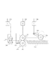
図7(a)に、混載サイズ原稿搬送モードでの制御タイミングチャートを示す。図中上段は分離後センサ11の出力信号、中段はピックアップモータ39の駆動信号、下段は分離モータ37の駆動信号のタイミングチャートを示している。混載サイズ原稿搬送モードでは、分離モータ37の停止タイミングは最小搬送可能サイズ長(B6サイズ)がピックアップローラ2を通過するタイミングである。従って、原稿後端が分離ローラ対3を通過時(分離後センサ11がオフ)には分離モータ37は停止している。また、図10(a)から分かるように、原稿の後端が分離後センサ11がオフになってからピックアップローラ2を降下させている。即ち、原稿の後端が確実にピックアップローラ2を通過してからピックアップローラ2を降下させている。そのため、後述の同一サイズ原稿搬送モードよりも生産性は低下するが、図9及び図10で説明した原稿の重送やジャムの問題は発生しない。なお、分離後センサ11と原稿トレイ1との間に原稿の後端を検知するセンサを配置できるならば、そのセンサがオンからオフになったタイミングでピックアップローラ2を降下させてもよい。
FIG. 7A shows a control timing chart in the mixed size document conveyance mode. In the figure, the upper part shows the output signal of the post-separation sensor 11, the middle part shows the drive signal for the
<同一サイズ原稿搬送モード>
次にコントローラ部200より原稿流し読みモードで、混載モードが通知されなかった場合の画像読取部100のCPU12により実行される制御フローを図6において説明する。ステップS1000で、混載サイズ原稿搬送モードが通知されていない場合、CPU12は原稿トレイ1には長さの同じ原稿束が積載されているものとして同一サイズ原稿搬送モードで動作させる(S1002)。まず、CPU12はピックアップローラ2を降下させた状態で、分離モータ37を駆動して1枚目の給紙を開始する(S3000)。CPU12は、1枚目のシートの先端を分離後センサ11で検知してから所定時間後、先端が引抜ローラ対6に到達したと判断して、ピックアップモータ39を回転させ、ピックアップローラ2を上昇させる(S3002)。
<Same size document transport mode>
Next, a control flow executed by the
次に、原稿給送装置が搬送可能な最小のサイズの原稿(B6サイズ)の後端が、ピックアップローラ2を通過するタイミングを、分離モータ37を停止するタイミングとして設定する(S3002)。CPU12は、1枚目のシートの後端が分離後センサ11を通過、即ち、分離後センサ11がオフしレジ前センサ14がオンしたか否かを判断する(S3006)。分離後センサ11がオフしレジ前センサ14がオンすると、CPU12は前述の原稿長さ検出制御によって1枚目のシート長さLを式1または式2を用いて算出し、コントローラ部200に通知する(S3004)。なお、上述したように、分離後センサ11だけで原稿サイズを算出してもよい。CPU12は分離後センサ11がオフしたことに応じてピックアップモータ39を回転させ、ピックアップローラ2を降下させる(S3005)。ピックアップローラ2の降下後、原稿検知センサ7がオンであれば、CPU12は、原稿トレイ1にシートが残っていると判断して(S3006)、分離モータ37を駆動して2枚目の原稿の給紙を開始する(S3007)。
Next, the timing at which the trailing edge of the minimum size document (B6 size) that can be conveyed by the document feeder passes through the
CPU12は、2枚目の原稿の給紙開始後、その先端が引抜ローラ対6に到達するタイミングで、ピックアップモータ39を回転させ、ピックアップローラ2を上昇させる(S3008)。更に、CPU12は、先端が引抜ローラ対6に到達したタイミングで、分離モータ37の停止タイミングを決定する。3枚目以降の原稿の給紙に関しては、CPU12は、1枚目で検知したサイズLに基づいて、原稿の後端がピックアップローラ2を通過するであろうタイミングを決定する。そして、CPU12は決定したタイミングに基づいてタイマー機能(図示せず)を使用してピックアップモータ39を回転させてピックアップローラ2を降下させ、分離モータ37を停止する設定を行う(S3009)。
After starting the feeding of the second original, the
その後、CPU12は、分離後センサ11がオフしレジ前センサ14がオンになったか否かを判断する(S3010)。分離後センサ11がオフしレジ前センサ14がオンの場合、CPU12は、2枚目のシートのサイズL’を式1または式2を用いて計算する(S3011)。このときCPU12は、L’から1枚目のシート長さLを引いた値が所定長さTh1(本実施形態では50mm)よりも短いか否かを判断する(S3012)。L’−L<Th1の場合、CPU12は1枚目の原稿長より2枚目の原稿長が短いと判断して、分離モータ37を停止する(S3015)。CPU12は更に、ピックアップローラ1を降下させ(S2005)、以降、混載サイズ搬送モードに切り替える。
Thereafter, the
また、S3010で分離後センサ11がオン状態の場合、その時点で分離後センサ11がオフと仮定した場合でのサイズL’’を式1または式2を用いて計算する(S3016)。このときCPU12は、L’’−Lの値が所定長さTh2(本実施形態では50mm)よりも長いか否かを判断する(S3017)。L’’−L>Th2の場合、CPU12は2枚目の原稿長が1枚目の原稿長よりも長いと判断して、1枚目の原稿の長さに基づいて降下させたピックアップローラ2を直ちに上昇させ(S3018)、混載サイズ搬送モードに切り替える。即ち、1枚目の原稿サイズで想定した後端通過タイミングになっても分離後センサ11がオンのままであれば、CPU12は、ピックアップローラ2を直ちに上昇させ、混載サイズ原稿搬送モードに切り替える。ステップS3017で2枚目の原稿長L’’が1枚目の原稿長Lよりも所定長さTh2以上長いと判断されない場合、CPU12は分離後センサ11がオフになるまで、所定時間毎にS3010で分離後センサ11及びレジ前センサ14のチェックを行う。なお、本実施形態では所定時間を10msとしている。
If the post-separation sensor 11 is on in S3010, the size L ″ when the post-separation sensor 11 is assumed to be off at that time is calculated using
また、ステップS3012で、L’−L>Th1でない場合、CPU12は、1枚目のサイズと2枚目のサイズが同じであると判断して、原稿検知センサ7がオフになるまで、給紙動作を繰り返す(S3013)。
If L′−L> Th1 is not satisfied in step S3012, the
図7(b),(c),(d)に、上記の同一サイズ原稿搬送モードでの制御タイミングチャートを示す。図7(a)と同様、図中上段は分離後センサ11の出力信号、中段はピックアップモータ39の駆動信号、下段は分離モータ37の駆動信号のタイミングチャートを示している。
FIGS. 7B, 7C, and 7D are control timing charts in the same size document transport mode. Similarly to FIG. 7A, the upper part of the drawing shows the output signal of the post-separation sensor 11, the middle part shows a timing chart of the driving signal of the
図7(b)は、同一サイズ原稿搬送モードで原稿束の各原稿のサイズが同一であった場合のタイミングチャートを示している。この場合、分離モータ37の停止タイミング及びピックアップローラ2の降下タイミングは1枚目で検出した原稿長の原稿がピックアップローラ2を抜けるタイミングに設定している。従って、原稿束の各原稿のサイズが同一であった場合には、図9と図10で説明した重送やジャムの問題は発生しない。また、3枚目以降の原稿に対しては、1枚目の原稿長さに基づいて、分離後センサ11がオフする前にピックアップローラ2を降下させているので、次の原稿の給紙準備を早くして、高生産性を維持できる。
FIG. 7B shows a timing chart when the size of each document in the document bundle is the same in the same size document transport mode. In this case, the stop timing of the
図7(c)は、同一サイズ原稿搬送モードであるが、2枚目の原稿が1枚目よりも短い場合のタイミングチャートを示している。この場合、2枚目の原稿の後端通過により分離後センサ11がオフした時点で、2枚目の原稿が1枚目よりも短いと判断して、すぐに分離モータ37を停止することで、図10で説明したような次原稿の分離ローラ対3への引き込み現象を低減することができる。
FIG. 7C shows a timing chart when the second document is shorter than the first document in the same size document transport mode. In this case, when the post-separation sensor 11 is turned off by passing the trailing edge of the second document, it is determined that the second document is shorter than the first, and the
図7(d)は、同一サイズ原稿搬送モードであるが、2枚目の原稿が1枚目よりも長い場合のタイミングチャートを示している。この場合、3枚目の原稿の給紙に関して、1枚目の原稿サイズに基づいてピックアップローラ2を降下させた後、2枚目1枚目の原稿サイズで想定したタイミングでも分離後センサ11がオフせずに1枚目よりも長いと判断される。そのときは、すぐにピックアップローラ2を上昇することで、図4で説明したような次原稿との重送現象を低減することができる。
FIG. 7D shows a timing chart when the second document is longer than the first document in the same size document transport mode. In this case, regarding the feeding of the third document, after the
以上述べたように、同一サイズ原稿搬送モードでは、1枚目の原稿長に基づいて、原稿後端が分離後センサ11を通過する前に、分離モータ37とピックアップローラ2の降下のタイミングを設定する。従って、混載サイズ原稿搬送モードに比べて、早く次の原稿を給紙可能状態にでき、原稿読取の生産性を上げることができる。また、同一サイズ原稿搬送モードでも、2枚目以降の原稿長さが1枚目の長さと異なることを検出した場合には、残りの原稿束にもサイズの異なる原稿が混ざっている可能性が高い。そこで、同一サイズ原稿搬送モードを中断し、混載サイズ原稿搬送モードの制御に切り替える。従って、シート束が全て同じサイズであった場合には高生産性を維持でき、シート束の中に異なる長さのシートが混ざっている場合でも重送やジャムの低減することができる。
As described above, in the same size document conveyance mode, the timing of lowering the
1 原稿トレイ
2 ピックアップローラ
3 分離ローラ対
4 フィードローラ
5 リタードローラ
6 引抜ローラ対
7 原稿検知センサ
11 分離後センサ
12 CPU
13 搬送ローラ対
37 分離モータ
38 搬送モータ
39 ピックアップモータ
101 CPU
DESCRIPTION OF
13 Conveying
Claims (9)
前記原稿トレイに積載された原稿上に当接して原稿を送り出し、送り出し後に前記原稿トレイ上の原稿から離間するピックアップローラと、
重送された原稿を分離可能な分離手段であって、前記ピックアップローラにより送り出された原稿をさらに搬送する分離手段と、
原稿の長さを検出する長さ検出手段と、
前記原稿トレイよりも下流側に設けられ、前記送り出された原稿の後端を検出する原稿センサと、
前記原稿トレイからの原稿の送り出しを制御する制御手段であって、前記原稿センサが原稿の後端を検出したことに応じて決定されるタイミングで、前記送り出された原稿の次の原稿に前記ピックアップローラを当接させる第1モードと、3枚目以降の各原稿については、前記原稿センサが直前に送り出された原稿の後端を検出するよりも前のタイミングであって且つ前記長さ検出手段により検出された1枚目の原稿の長さに応じて決定されるタイミングで前記原稿トレイ上の原稿に前記ピックアップローラを当接させる第2モードを選択可能な制御手段と、
を有し、
前記制御手段は、前記第2モードで原稿の送り出しを制御している場合に、前記1枚目の原稿の長さよりも短い原稿の長さが検出されると、前記第2モードから前記第1モードへ切り替え、且つ前記分離手段の駆動を停止することを特徴とする原稿給送装置。 A document tray for loading multiple documents,
A pick-up roller that abuts on a document stacked on the document tray and feeds the document, and separates from the document on the document tray after feeding;
Separation means capable of separating the multi-fed originals, further separating the originals fed by the pickup roller;
A length detecting means for detecting the length of the document;
A document sensor that is provided downstream of the document tray and detects a trailing edge of the fed document;
Control means for controlling delivery of a document from the document tray, wherein the pickup is added to a document next to the delivered document at a timing determined according to detection of a trailing edge of the document by the document sensor. For the first mode in which the rollers are brought into contact with each of the third and subsequent documents, the length detection unit is at a timing before the document sensor detects the trailing edge of the document that has been sent immediately before. Control means capable of selecting a second mode in which the pickup roller contacts the document on the document tray at a timing determined according to the length of the first document detected by
Have
In the second mode, the control means controls the first mode from the second mode when the length of the original shorter than the length of the first original is detected in the second mode. A document feeding apparatus characterized in that the mode is switched and the driving of the separating means is stopped.
Priority Applications (2)
| Application Number | Priority Date | Filing Date | Title |
|---|---|---|---|
| JP2008321631A JP5341493B2 (en) | 2008-12-17 | 2008-12-17 | Sheet transport device |
| US12/636,355 US8011651B2 (en) | 2008-12-17 | 2009-12-11 | Original-feeding device |
Applications Claiming Priority (1)
| Application Number | Priority Date | Filing Date | Title |
|---|---|---|---|
| JP2008321631A JP5341493B2 (en) | 2008-12-17 | 2008-12-17 | Sheet transport device |
Publications (3)
| Publication Number | Publication Date |
|---|---|
| JP2010143695A JP2010143695A (en) | 2010-07-01 |
| JP2010143695A5 JP2010143695A5 (en) | 2013-03-14 |
| JP5341493B2 true JP5341493B2 (en) | 2013-11-13 |
Family
ID=42239561
Family Applications (1)
| Application Number | Title | Priority Date | Filing Date |
|---|---|---|---|
| JP2008321631A Active JP5341493B2 (en) | 2008-12-17 | 2008-12-17 | Sheet transport device |
Country Status (2)
| Country | Link |
|---|---|
| US (1) | US8011651B2 (en) |
| JP (1) | JP5341493B2 (en) |
Families Citing this family (16)
| Publication number | Priority date | Publication date | Assignee | Title |
|---|---|---|---|---|
| JP5321146B2 (en) * | 2009-03-04 | 2013-10-23 | 株式会社リコー | Document feeder and image forming apparatus |
| JP5014467B2 (en) * | 2010-06-14 | 2012-08-29 | シャープ株式会社 | Document conveying apparatus, image reading apparatus, and image forming apparatus |
| JP2012001301A (en) * | 2010-06-15 | 2012-01-05 | Ricoh Co Ltd | Automatic document feeder and image forming apparatus including the same |
| JP5804352B2 (en) * | 2010-11-11 | 2015-11-04 | 株式会社リコー | Sheet material conveying apparatus, image reading apparatus, and image forming apparatus |
| JP5671999B2 (en) * | 2010-12-24 | 2015-02-18 | 株式会社リコー | Sheet feeding apparatus, sheet reading apparatus, and image forming apparatus |
| JP6570251B2 (en) * | 2015-01-14 | 2019-09-04 | キヤノン株式会社 | Image reading device |
| JP6299645B2 (en) * | 2015-03-27 | 2018-03-28 | 京セラドキュメントソリューションズ株式会社 | Image reading apparatus and image reading method |
| JP6666025B2 (en) * | 2015-06-10 | 2020-03-13 | キヤノン株式会社 | Sheet feeding apparatus, reading apparatus using the same, and image forming apparatus |
| US10306088B2 (en) | 2017-09-14 | 2019-05-28 | Kabushiki Kaisha Toshiba | Image forming apparatus with a reading controller that has two modes and associated control method |
| US10676300B2 (en) * | 2017-12-22 | 2020-06-09 | Canon Kabushiki Kaisha | Sheet feeding apparatus and image forming apparatus |
| KR20190125081A (en) * | 2018-04-27 | 2019-11-06 | 휴렛-팩커드 디벨롭먼트 컴퍼니, 엘.피. | Controlling paper intercal for scanning image |
| JP7275655B2 (en) * | 2018-08-29 | 2023-05-18 | セイコーエプソン株式会社 | Media feeding device, image reading device |
| EP3617106B1 (en) | 2018-08-29 | 2024-01-03 | Seiko Epson Corporation | Medium feeding apparatus, image reading apparatus, and medium feeding method |
| JP7255350B2 (en) * | 2019-05-17 | 2023-04-11 | 京セラドキュメントソリューションズ株式会社 | Paper conveying device, image reading device, and image forming device |
| JP7271322B2 (en) * | 2019-06-07 | 2023-05-11 | キヤノン株式会社 | sheet feeder |
| JP7379049B2 (en) | 2019-09-30 | 2023-11-14 | キヤノン株式会社 | Sheet feeding device, image reading device, and image forming device |
Family Cites Families (14)
| Publication number | Priority date | Publication date | Assignee | Title |
|---|---|---|---|---|
| JPS63235229A (en) * | 1987-03-25 | 1988-09-30 | Konica Corp | Document transporting device |
| JP2896685B2 (en) * | 1989-09-19 | 1999-05-31 | コニカ株式会社 | Automatic document feeder |
| EP0842880B1 (en) * | 1996-11-18 | 2003-10-29 | Canon Kabushiki Kaisha | Image forming apparatus |
| JPH11272021A (en) * | 1998-01-26 | 1999-10-08 | Minolta Co Ltd | Copying device |
| US6076821A (en) * | 1998-09-14 | 2000-06-20 | Lexmark International, Inc. | Method and apparatus for feeding sheets |
| US6126160A (en) * | 1999-04-12 | 2000-10-03 | Eastman Kodak Company | Sheet feeding control for image reading device |
| JP2001139169A (en) * | 1999-11-18 | 2001-05-22 | Ricoh Co Ltd | Automatic document feeder |
| JP2001146329A (en) * | 1999-11-19 | 2001-05-29 | Canon Inc | Paper feeding device, and image forming device or image reading device provided with the same |
| JP4040394B2 (en) * | 2002-08-27 | 2008-01-30 | 株式会社リコー | Sheet conveying apparatus and image reading apparatus |
| JP4075755B2 (en) * | 2003-09-22 | 2008-04-16 | トヨタ自動車株式会社 | Method for suppressing filter overheating of internal combustion engine |
| JP4249050B2 (en) * | 2004-02-05 | 2009-04-02 | 株式会社リコー | Paper feeding device and image forming apparatus |
| JP4382561B2 (en) * | 2004-04-09 | 2009-12-16 | ニスカ株式会社 | Automatic document feeder |
| US7275740B2 (en) * | 2005-01-06 | 2007-10-02 | Lexmark International, Inc. | Method and apparatus for feeding sheets |
| EP1837296B1 (en) * | 2006-03-24 | 2013-08-28 | Kabushiki Kaisha Toshiba | Device and method for taking out sheets |
-
2008
- 2008-12-17 JP JP2008321631A patent/JP5341493B2/en active Active
-
2009
- 2009-12-11 US US12/636,355 patent/US8011651B2/en active Active
Also Published As
| Publication number | Publication date |
|---|---|
| US20100148423A1 (en) | 2010-06-17 |
| US8011651B2 (en) | 2011-09-06 |
| JP2010143695A (en) | 2010-07-01 |
Similar Documents
| Publication | Publication Date | Title |
|---|---|---|
| JP5341493B2 (en) | Sheet transport device | |
| JP5321146B2 (en) | Document feeder and image forming apparatus | |
| JP5219564B2 (en) | Sheet feeding apparatus, image reading apparatus, and image forming apparatus | |
| US10148851B2 (en) | Image reading apparatus and image reading method | |
| US10455114B2 (en) | Image reading apparatus, control method for image reading apparatus, and storage medium | |
| US8128081B2 (en) | Document feeding apparatus | |
| US20220021777A1 (en) | Document reading apparatus, control method thereof, and storage medium | |
| JP2012056643A (en) | Sheet conveying device, document conveying device, sheet reader, and image forming apparatus | |
| US8905400B2 (en) | Sheet feeding device and image processing apparatus | |
| JP2011051692A (en) | Sheet feeder and image reader using the same | |
| JP2017024848A (en) | Image reading device, and image formation device | |
| US20220024708A1 (en) | Reading apparatus, control method for reading apparatus, and storage medium | |
| JP2006140902A (en) | Image reading apparatus | |
| JP2022092222A (en) | Sheet carrier, image reader and method of carrying sheet | |
| JP3875003B2 (en) | Paper transport device | |
| JP2016088693A (en) | Sheet feeding device | |
| JP2005015122A (en) | Automatic document conveying device and image formation device provided with this | |
| JP3747986B2 (en) | Document feeder | |
| JP5771654B2 (en) | Sheet processing device | |
| JP2005263452A (en) | Automatic document feeder | |
| JP5102575B2 (en) | Monochrome multi-level document reader, color document reader, and image forming apparatus | |
| JP2011088728A (en) | Document carrying device and image forming device using the same | |
| JP2003306248A (en) | Document carrying device and image reading device | |
| JP2022036660A (en) | Automatic conveyance device, image reading device and image forming device | |
| JP4574519B2 (en) | Automatic document feeder |
Legal Events
| Date | Code | Title | Description |
|---|---|---|---|
| RD01 | Notification of change of attorney |
Free format text: JAPANESE INTERMEDIATE CODE: A7421 Effective date: 20100630 |
|
| A521 | Request for written amendment filed |
Free format text: JAPANESE INTERMEDIATE CODE: A523 Effective date: 20111219 |
|
| A621 | Written request for application examination |
Free format text: JAPANESE INTERMEDIATE CODE: A621 Effective date: 20111219 |
|
| A521 | Request for written amendment filed |
Free format text: JAPANESE INTERMEDIATE CODE: A523 Effective date: 20130109 |
|
| A977 | Report on retrieval |
Free format text: JAPANESE INTERMEDIATE CODE: A971007 Effective date: 20130122 |
|
| A131 | Notification of reasons for refusal |
Free format text: JAPANESE INTERMEDIATE CODE: A131 Effective date: 20130212 |
|
| A521 | Request for written amendment filed |
Free format text: JAPANESE INTERMEDIATE CODE: A523 Effective date: 20130412 |
|
| TRDD | Decision of grant or rejection written | ||
| A01 | Written decision to grant a patent or to grant a registration (utility model) |
Free format text: JAPANESE INTERMEDIATE CODE: A01 Effective date: 20130716 |
|
| A61 | First payment of annual fees (during grant procedure) |
Free format text: JAPANESE INTERMEDIATE CODE: A61 Effective date: 20130808 |
|
| R151 | Written notification of patent or utility model registration |
Ref document number: 5341493 Country of ref document: JP Free format text: JAPANESE INTERMEDIATE CODE: R151 |