JP7440552B2 - shroud - Google Patents
shroud Download PDFInfo
- Publication number
- JP7440552B2 JP7440552B2 JP2022021065A JP2022021065A JP7440552B2 JP 7440552 B2 JP7440552 B2 JP 7440552B2 JP 2022021065 A JP2022021065 A JP 2022021065A JP 2022021065 A JP2022021065 A JP 2022021065A JP 7440552 B2 JP7440552 B2 JP 7440552B2
- Authority
- JP
- Japan
- Prior art keywords
- shroud
- inner shroud
- tank
- width direction
- vehicle width
- Prior art date
- Legal status (The legal status is an assumption and is not a legal conclusion. Google has not performed a legal analysis and makes no representation as to the accuracy of the status listed.)
- Active
Links
Images


Landscapes
- Automatic Cycles, And Cycles In General (AREA)
Description
本発明は、シュラウドに関する。 The present invention relates to a shroud.
特許文献1には、鞍乗型車両に設けられた燃料タンクの側面の少なくとも一部をシュラウドで覆うことが開示されている。 Patent Document 1 discloses that at least a portion of the side surface of a fuel tank provided in a straddle-type vehicle is covered with a shroud.
シュラウドは、鞍乗型車両の車体又は燃料タンクに取り付けられる。鞍乗型車両の動作中、車体の振動がシュラウドに伝わると、振動によってシュラウドに割れが発生する可能性がある。 The shroud is attached to the body or fuel tank of the saddle type vehicle. When vibrations from the vehicle body are transmitted to the shroud during operation of a straddle-type vehicle, the shroud may crack due to the vibrations.
本発明は、上述した課題を解決することを目的とする。 The present invention aims to solve the above-mentioned problems.
本発明の態様は、鞍乗型車両に設けられた燃料タンクの側面の少なくとも一部を覆うシュラウドであって、前記シュラウドは、前記鞍乗型車両の車幅方向の内側に配置されたインナーシュラウドと、前記車幅方向の外側に配置され、前記インナーシュラウドに連結されるアウターシュラウドと、を備え、前記インナーシュラウドは、前記車幅方向に向かって凹む少なくとも1つの凹部と、前記車幅方向に向かって突出する複数の凸部とが形成された凹凸部を有し、前記凹凸部のうち、少なくとも1つの前記凸部は、前記インナーシュラウドの前端部に形成されている。 An aspect of the present invention is a shroud that covers at least a part of a side surface of a fuel tank provided in a straddle-type vehicle, the shroud comprising an inner shroud disposed inside the straddle-type vehicle in the vehicle width direction. and an outer shroud disposed on the outside in the vehicle width direction and connected to the inner shroud, the inner shroud having at least one recess recessed in the vehicle width direction, and an outer shroud that is recessed in the vehicle width direction. The inner shroud has an uneven portion in which a plurality of protrusions projecting toward the inner shroud are formed, and at least one of the uneven portions is formed at the front end portion of the inner shroud.
本発明では、インナーシュラウドに凹凸部を設けることにより、振動に対するインナーシュラウドの耐久性を向上させることができる。これにより、シュラウドの割れの発生を抑制することができる。 In the present invention, by providing the inner shroud with the uneven portion, the durability of the inner shroud against vibration can be improved. This makes it possible to suppress the occurrence of cracks in the shroud.
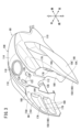
図1は、自動二輪車10(鞍乗型車両)の左側面図である。図2は、自動二輪車10の平面図である。以下の説明では、自動二輪車10が前進する方向を前方として、前後、左右及び上下の方向を説明する。
FIG. 1 is a left side view of a motorcycle 10 (straddle type vehicle). FIG. 2 is a plan view of the
自動二輪車10は、車体フレーム12(車体)を備える。車体フレーム12は、ヘッドパイプ14と、メインフレーム16と、センターフレーム18と、ダウンフレーム20と、左右一対のシートフレーム22と、左右一対のサブフレーム24と、左右一対のステップフレーム26とを備える。
The
ヘッドパイプ14は、車体フレーム12の前端部の一部である。メインフレーム16は、ヘッドパイプ14から後方且つ斜め下方に延びている。センターフレーム18は、メインフレーム16の後端部から下方に延びている。センターフレーム18の下部には、ピボット支持部(不図示)が設けられている。ダウンフレーム20は、メインフレーム16よりも下方で、ヘッドパイプ14から後方且つ斜め下方に延びている。
The
左右のシートフレーム22の各々は、メインフレーム16の後端部から後方に延びている。左右のサブフレーム24の各々は、センターフレーム18の下部とシートフレーム22とを連結する。左右のステップフレーム26の各々は、センターフレーム18の下部から後方に延びている。
Each of the left and
自動二輪車10は、前輪28と、後輪30と、フロントフェンダ32と、リアフェンダ34と、エンジン36と、シート38と、燃料タンク40とをさらに備える。図2に示すように、シート38及び燃料タンク40は、前後方向に沿った自動二輪車10の中心軸41上に位置している。
The
図1に示すように、ヘッドパイプ14には、フロントフォーク42が揺動可能に支持されている。フロントフォーク42は、ステアリングシャフト(不図示)と、左右一対のフォークパイプ44と、トップブリッジ46と、ボトムブリッジ48とを有する。
As shown in FIG. 1, a
ステアリングシャフトは、ヘッドパイプ14に回動可能に支持されている。左右のフォークパイプ44は、前輪28の左右両側に配置されている。左右のフォークパイプ44の下端部には、前輪28が回転可能に支持されている。トップブリッジ46は、ステアリングシャフトの上端部に固定されている。トップブリッジ46は、左右のフォークパイプ44の上端部を連結する。トップブリッジ46の上部には、ハンドル50が固定されている。ボトムブリッジ48は、ステアリングシャフトの下端部に固定されている。ボトムブリッジ48は、左右のフォークパイプ44を連結する。従って、前輪28は、フロントフォーク42を介して、車体フレーム12の前端部に操舵可能に支持されている。フロントフェンダ32は、前輪28を上方から覆う。
The steering shaft is rotatably supported by the
ピボット支持部には、ピボット軸52が連結されている。ピボット軸52には、スイングアーム54の前端部が支持されている。スイングアーム54は、前端部が揺動可能にピボット軸52に支持されている。スイングアーム54は、ピボット軸52から後方に延びている。スイングアーム54は、後輪30の左側方にまで延びている。スイングアーム54の後端部は、後輪30を回転可能に支持する。リアフェンダ34は、左右のシートフレーム22の後端部から後方に延びている。リアフェンダ34は、後輪30を上方から覆う。
A
エンジン36は、メインフレーム16の下方で、センターフレーム18とダウンフレーム20との間に配置されている。エンジン36は、クランクケース56と、シリンダ部58とを有する。クランクケース56は、左右方向(車幅方向)に延びるクランク軸(不図示)を支持する。クランクケース56の後部には、変速機(不図示)が内蔵されている。
The
シリンダ部58は、クランクケース56の前部から、前方且つ斜め上方に延びている。シリンダ部58には、吸気装置(不図示)と、排気装置60とが接続されている。吸気装置は、シリンダ部58の後部に接続されている。排気装置60は、シリンダ部58の前部に接続されている。排気装置60は、排気管62と、マフラー64とを有する。排気管62は、シリンダ部58の前面から下方に延び、クランクケース56の下方で屈曲して後方に延びている。マフラー64は、排気管62の後端に接続され、後方に延びている。マフラー64は、後輪30の右側方にまで延びている(図2参照)。
The
シート38は、左右のシートフレーム22に固定されている。シート38は、前側シート66と、後側シート68とを有する。前側シート66は、左右のシートフレーム22の前側に配置されている。前側シート66には、運転者が着座する。後側シート68は、前側シート66の後方に設けられている。後側シート68は、左右のシートフレーム22の後側に配置されている。後側シート68には、同乗者が着座する。
The
左右のステップフレーム26の各々の前端部には、ステップ70が設けられている。前側シート66に着座した運転者は、左右の足を各ステップ70に掛ける。左右のステップフレーム26の各々の後端部には、ピリオンステップ72が設けられている。後側シート68に着座した同乗者は、左右の足を各ピリオンステップ72に掛ける。センターフレーム18の下部には、メインスタンド74が設けられている。
A
燃料タンク40は、ヘッドパイプ14とシート38との間に配置されている。具体的には、燃料タンク40は、前側シート66の前方で、且つ、ヘッドパイプ14の後方に配置されている。燃料タンク40は、メインフレーム16の上部に取り付けられている。
The
自動二輪車10は、車体フレーム12、燃料タンク40等を覆う車体カバー76をさらに備える。車体カバー76は、フロントカバー78と、タンクカバー80と、左右一対のセンターカバー82と、リアカバー84と、アンダーカバー86と、左右一対のシュラウド88とを有する。
The
フロントカバー78は、ヘッドパイプ14及び左右のフォークパイプ44の上部を前方から覆う。タンクカバー80は、燃料タンク40を覆う。左右のセンターカバー82の各々は、前側シート66の下方を覆う。リアカバー84は、左右のセンターカバー82の後方で、シート38の下方を覆う。アンダーカバー86は、クランクケース56の下部を、前方、側方及び下方から覆う。
The
左右のシュラウド88の各々は、タンクカバー80及びダウンフレーム20に連結されている。左右のシュラウド88の各々は、燃料タンク40の側面の一部と、ヘッドパイプ14の一部と、メインフレーム16の前部と、ダウンフレーム20の上部とを覆う。タンクカバー80及び左右のシュラウド88の詳細な構成は、後述する。
Each of the left and
次に、本実施形態の特徴的な構成について、図3~図15を参照しながら説明する。特徴的な構成とは、タンクカバー80及び左右のシュラウド88の構成である。
Next, the characteristic configuration of this embodiment will be explained with reference to FIGS. 3 to 15. The characteristic configuration is the configuration of the
燃料タンク40(図12参照)は、樹脂製である。燃料タンク40は、タンク上部90と、タンク下部92とを備える。
The fuel tank 40 (see FIG. 12) is made of resin. The
タンク下部92は、下方に凹み、且つ、上方が開放された椀状の形状を有する。タンク下部92の外縁には、フランジ94が形成されている。タンク下部92は、前後方向に沿って、傾斜して配置されている。
The tank
タンク上部90は、上方に膨出し、且つ、下方が開放された椀状の形状を有する。タンク上部90の外縁には、フランジ96が形成されている。タンク上部90のフランジ96と、タンク下部92のフランジ94とを重ね合わせることで、燃料タンク40が構成される。なお、タンク上部90の上面98は、燃料タンク40の上面100を形成する。以下の説明では、燃料タンク40の上面100を、タンク上部90の上面98と呼称する場合がある。タンク上部90の上面98には、給油口102が設けられている。給油口102は、タンクキャップ104によって閉じられている。タンク上部90の前部には、前方且つ斜め上方にステー106が延びている。
The tank
タンクカバー80及び左右のシュラウド88(図3参照)は、樹脂製である。具体的には、タンクカバー80及び左右のシュラウド88は、ABS樹脂製である。
The
図7に示すように、タンクカバー80は、センターカバー108と、左右一対のサイドカバー110とを備える。
As shown in FIG. 7, the
センターカバー108は、燃料タンク40の上面100(図12参照)の少なくとも一部を覆う。図2に示すように、センターカバー108は、自動二輪車10の中心軸41上を前後方向に延びている。センターカバー108は、燃料タンク40の上方で、タンク上部90(図12参照)の上面98のうち、中心軸41周辺の部分を覆っている。
図8に示すように、センターカバー108は、タンク上部90(図12参照)を覆うように湾曲した板状部材である。センターカバー108は、前端部112、本体部114及び後端部116を有する。
As shown in FIG. 8, the
本体部114は、前後方向に延びている。本体部114は、タンク上部90の上面98(図12参照)に沿って湾曲している。本体部114には、タンクキャップ104(図12参照)が挿通可能な開口118が形成されている。
The
前端部112は、本体部114の前端から、前方且つ斜め下方に延びている。本体部114と前端部112との連結箇所には、取付部120が左右両側に形成されている。左右の取付部120は、下方に凹む凹部である。左右の取付部120の各々には、上下方向に貫通する孔122が形成されている。2つの孔122の各々には、ボルト124(図12参照)が挿通する。なお、前端部112の先端には、メインフレーム16(図1参照)との干渉をさけるため、半円状の切欠126が形成されている。
The
図9に示すように、後端部116は、本体部114の後端から、後方且つ斜め下方に延びている。後端部116は、連結部128と、狭幅部130と、取付部132と、左右一対の補強部134とを有する。
As shown in FIG. 9, the
連結部128は、本体部114の後端に連結されている。連結部128は、本体部114の後部を下方に屈曲することで形成される。従って、左右方向における連結部128の幅は、左右方向における本体部114の幅と略同じである。
The connecting
図11に示すように、狭幅部130は、連結部128の後端に連結されている。狭幅部130は、連結部128から離れる程、左右方向の幅が狭くなる。取付部132は、狭幅部130の後端に連結されている。従って、狭幅部130は、取付部132に近づく程、左右方向の幅が狭くなる。
As shown in FIG. 11, the
取付部132は、狭幅部130の後端から後方に延びている。取付部132には、上下方向に貫通する孔136が形成されている。孔136には、ボルト138(図12参照)が挿通する。ボルト138は、タンク上部90及びタンク下部92の各フランジ94、96に形成されたボルト孔(不図示)に螺合する。これにより、センターカバー108の後端部116は、燃料タンク40に固定される。
The
取付部132の後部には、2つの切欠部140が形成されている。なお、切欠部140は、取付部132に少なくとも1つ形成されていればよい。補強部134は、後端部116の左右両側に設けられている。左側の補強部134は、狭幅部130の左側と、取付部132の左側とを連結する。右側の補強部134は、狭幅部130の右側と、取付部132の右側とを連結する。左右の補強部134は、略台形状の壁部である。なお、後端部116は、少なくとも1つの補強部134を有すればよい。また、補強部134は、壁状に形成されていればよい。
Two
図9に示すように、本体部114の左右両側には、車幅方向外側に突出する複数の連結部142が形成されている。複数の連結部142は、前後方向に沿って、任意の間隔で、本体部114の左右両側に形成されている。複数の連結部142は、左右のサイドカバー110(図4参照)に形成された複数の連結部(不図示)に連結される。これにより、センターカバー108と左右のサイドカバー110とが連結される。
As shown in FIG. 9, a plurality of connecting
図12に示すように、タンクカバー80は、任意のクリアランスを隔てて、燃料タンク40を覆っている。センターカバー108の底面144は、タンク上部90の上面98と向かい合っている。図10に示すように、センターカバー108の底面144には、複数のリブ部146(第1リブ部148、第2リブ部150)が形成されている。複数のリブ部146は、センターカバー108の底面144からタンク上部90の上面98に向かって突出する板状部である。
As shown in FIG. 12, the
第1リブ部148は、相対的に高いリブである。第1リブ部148は、センターカバー108の底面144において、複数の取付部120、132(図7参照)の間に形成されている。具体的には、第1リブ部148は、本体部114の底面152において、本体部114の底面152とタンク上部90の上面98とのクリアランスが相対的に狭い箇所に形成されている。より具体的には、第1リブ部148は、本体部114の底面152において、開口118と本体部114の後端との間に形成されている。第1リブ部148の形成箇所は、運転者が前側シート66(図1参照)に着座したときに、運転者と向かい合う箇所である。
The
第1リブ部148は、本体部114の底面152において、格子状に形成されている。図12に示すように、第1リブ部148は、タンク上部90の上面98と接触するように、本体部114の底面152に形成されている。
The
第2リブ部150は、第1リブ部148よりも低いリブである。図10に示すように、第2リブ部150は、第1リブ部148の少なくとも一部を囲むように、センターカバー108の底面144に形成されている。具体的には、第2リブ部150は、センターカバー108の底面144における本体部114の開口118と後端部116の狭幅部130との間に形成されている。
The
第2リブ部150は、センターカバー108の底面144において、格子状に形成されている。なお、格子状の第2リブ部150は、格子状の第1リブ部148を囲んでいる。また、第2リブ部150の一部は、第1リブ部148に連結されている。
The
図12に示すように、第2リブ部150は、センターカバー108の底面144におけるタンク上部90の上面98とのクリアランスが相対的に広い箇所に形成されている。また、第2リブ部150は、タンク上部90の上面98と接触しないように、センターカバー108の底面144に形成されている。
As shown in FIG. 12, the
なお、本実施形態では、第1リブ部148は、センターカバー108の底面144におけるタンク上部90の上面98とのクリアランスが相対的に広い箇所に形成されてもよい。第2リブ部150は、センターカバー108の底面144におけるタンク上部90の上面98とのクリアランスが相対的に狭い箇所に形成されてもよい。この場合でも、第1リブ部148は、タンク上部90の上面98に接触するように、センターカバー108の底面144に形成される。
In this embodiment, the
図3に示すように、左右のサイドカバー110は、センターカバー108に連結されている。左側のサイドカバー110は、燃料タンク40(図2参照)の左側面を覆うように湾曲した板状部材である。右側のサイドカバー110は、燃料タンク40の右側面を覆うように湾曲した板状部材である。左右のサイドカバー110の各々の後端部は、ボルト(不図示)によって、メインフレーム16(図1参照)に固定されている。
As shown in FIG. 3, the left and right side covers 110 are connected to the
図7に示すように、左右のシュラウド88の各々は、サイドカバー110に連結されている。図1に示すように、左右のシュラウド88の各々は、サイドカバー110から前方且つ斜め下方に延びている。すなわち、図2に示すように、シュラウド88は、自動二輪車10の中心軸41を挟んで、タンクカバー80の左右両側に配置されている。左右のシュラウド88は、同じ構成を有している。そのため、以下の説明では、代表的に、いずれか一方のシュラウド88について説明する。
As shown in FIG. 7, each of the left and
図3に示すように、シュラウド88は、インナーシュラウド154と、アウターシュラウド156とを有する。インナーシュラウド154は、サイドカバー110の前方で、車幅方向の内側に配置されている。アウターシュラウド156は、インナーシュラウド154よりも車幅方向の外側に配置されている。図7に示すように、アウターシュラウド156は、前後方向に沿って、インナーシュラウド154の前端部158からサイドカバー110の中央部にかけて配置されている。アウターシュラウド156は、インナーシュラウド154と、サイドカバー110とに連結されている。具体的には、アウターシュラウド156は、インナーシュラウド154とサイドカバー110とに挟み込まれた状態で、インナーシュラウド154及びサイドカバー110に連結されている。
As shown in FIG. 3,
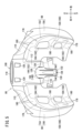
図5に示すように、インナーシュラウド154は、後方の燃料タンク40(図12参照)に近づく程、車幅方向の内側に湾曲する板状部材である。すなわち、インナーシュラウド154は、インナーシュラウド154の後部に近づくにつれて、燃料タンク40に近づくように湾曲している。図15に示すように、インナーシュラウド154は、インナーシュラウド154の後部に近づくにつれて、上下方向の幅が大きくなる。そのため、図14に示すように、インナーシュラウド154の上端部160及び下端部162は、インナーシュラウド154の後部に位置する。
As shown in FIG. 5, the
図13に示すように、インナーシュラウド154の上端部160及び下端部162には、取付部164、166がそれぞれ設けられている。
As shown in FIG. 13,
インナーシュラウド154の上端部160に設けられた取付部164は、水平方向に延びる板状部である。取付部164には、上記のボルト124が挿通する孔168が形成されている。ボルト124は、センターカバー108(図8参照)の取付部120の孔122と、インナーシュラウド154の取付部164の孔168とを挿通する。これにより、ボルト124は、タンク上部90のステー106に形成されたボルト孔(不図示)に螺合する。ボルト124がボルト孔に螺合することで、センターカバー108とインナーシュラウド154とは、タンク上部90に共締め固定される(図12参照)。
A mounting
インナーシュラウド154の下端部162に設けられた取付部166は、後方向に凹む凹部である。凹部には、ボルト170が挿通する孔172が形成されている。ボルト170は、孔172を挿通し、ダウンフレーム20に設けられたステー174のボルト孔(不図示)に螺合する。これにより、インナーシュラウド154は、ダウンフレーム20に固定される。
A mounting
図5に示すように、インナーシュラウド154は、凹凸部176を有する。凹凸部176は、少なくとも1つの凹部178と、複数の凸部180とから構成される。凹部178は、インナーシュラウド154の一部を車幅方向に向かって凹ませることにより形成される。凸部180は、インナーシュラウド154の一部を車幅方向に向かって突出させることにより形成される。
As shown in FIG. 5, the
具体的には、図14に示すように、インナーシュラウド154の上側及び下側で、車幅方向の外側に凹ませることにより、2つの凹部178が形成される。これにより、図15に示すように、2つの凹部178の周囲は、2つの凹部178に対して、車幅方向の内側に相対的に突出する。この結果、凹部178を囲むように、複数の凸部180が形成される。従って、インナーシュラウド154の前端部158は、凸部180として形成される。なお、図14に示すように、インナーシュラウド154では、インナーシュラウド154の前端部158、上部、下部、後部及び中央部が、2つの凹部178を囲む凸部180として形成されている。
Specifically, as shown in FIG. 14, two
図13に示すように、2つの凹部178の各々は、前後方向に沿って形成されている。2つの凹部178の各々は、インナーシュラウド154の後部に近づく程、上下方向の幅が広くなる(図15参照)。また、2つの凹部178の各々は、インナーシュラウド154の後部に近づく程、車幅方向の深さが深くなる(図13参照)。なお、本実施形態では、少なくとも1つの凹部178が前後方向に沿って形成されていればよい。また、少なくとも1つの凹部178が、インナーシュラウド154の後部に近づく程、上下方向の幅が広くなり、且つ、車幅方向の深さが深くなっていればよい。
As shown in FIG. 13, each of the two
図13に示すように、複数の凸部180のうち、インナーシュラウド154の前端部158及び後部以外の凸部180は、前後方向に沿って形成されている。これらの凸部180の各々は、インナーシュラウド154の後部に近づく程、上下方向の幅が広くなる。また、これらの凸部180の各々は、インナーシュラウド154の後部に近づく程、車幅方向の高さが高くなる。
As shown in FIG. 13, among the plurality of
なお、上記のように、2つの凹部178が車幅方向外側に凹むことで、複数の凸部180が車幅方向内側に相対的に突出する。そのため、車幅方向に沿った複数の凸部180の高さは、車幅方向外側における凹部178の底面からの高さである。また、本実施形態では、少なくとも1つの凸部180が前後方向に沿って形成されていればよい。また、少なくとも1つの凸部180が、インナーシュラウド154の後部に近づく程、上下方向の幅が広くなり、且つ、車幅方向の高さが高くなればよい。
Note that, as described above, the two
図3に示すように、インナーシュラウド154とアウターシュラウド156とが連結されることで、シュラウド88には、内部空間182(図5参照)が形成される。内部空間182には、ラジエータ、キャニスタ、各種の電装部品(不図示)等が配置される。2つの凹部178の各々の後部には、導入口184が形成されている。導入口184は、シュラウド88の内部空間182に外気を導入する。具体的には、自動二輪車10(図1参照)の走行中、導入口184は、外気である走行風を内部空間182に導入する。これにより、ラジエータ、キャニスタ及び電装部品は、走行風によって、好適に冷却される。
As shown in FIG. 3, by connecting the
図6に示すように、アウターシュラウド156の後部には、複数の排出口186が形成されている。導入口184(図5参照)から内部空間182に導入された走行風は、ラジエータ、キャニスタ及び電装部品からの熱で温められる。各排出口186は、温められた走行風(空気)を外部に排出する。
As shown in FIG. 6, a plurality of
なお、本発明は、上述した実施形態に限らず、本発明の要旨を逸脱することなく、種々の構成を取り得る。 Note that the present invention is not limited to the embodiments described above, and can take various configurations without departing from the gist of the present invention.
上記の実施形態から把握し得る発明について、以下に記載する。 The invention that can be understood from the above embodiments will be described below.
本発明の態様は、鞍乗型車両(10)に設けられた燃料タンク(40)の側面の少なくとも一部を覆うシュラウド(88)であって、前記シュラウド(88)は、前記鞍乗型車両(10)の車幅方向の内側に配置されたインナーシュラウド(154)と、前記車幅方向の外側に配置され、前記インナーシュラウド(154)に連結されるアウターシュラウド(156)と、を備え、前記インナーシュラウド(154)は、前記車幅方向に向かって凹む少なくとも1つの凹部(178)と、前記車幅方向に向かって突出する複数の凸部(180)とが形成された凹凸部(176)を有し、前記凹凸部(176)のうち、少なくとも1つの前記凸部(180)は、前記インナーシュラウド(154)の前端部(158)に形成されている。 An aspect of the present invention is a shroud (88) that covers at least a part of a side surface of a fuel tank (40) provided in the straddle-type vehicle (10), the shroud (88) (10) includes an inner shroud (154) disposed on the inner side in the vehicle width direction, and an outer shroud (156) arranged on the outer side in the vehicle width direction and connected to the inner shroud (154); The inner shroud (154) has an uneven portion (176) in which at least one recess (178) recessed toward the vehicle width direction and a plurality of convex portions (180) projecting toward the vehicle width direction are formed. ), and at least one of the convex portions (180) among the concavo-convex portions (176) is formed at the front end portion (158) of the inner shroud (154).
本発明では、インナーシュラウドに凹凸部を設けることにより、振動に対するインナーシュラウドの耐久性を向上させることができる。これにより、シュラウドの割れの発生を抑制することができる。 In the present invention, by providing the inner shroud with the uneven portion, the durability of the inner shroud against vibration can be improved. This makes it possible to suppress the occurrence of cracks in the shroud.
すなわち、鞍乗型車両の走行に伴う車体の振動等に起因して、シュラウドが破損することを抑制することができる。これにより、シュラウドの耐久性を向上させることができる。 That is, it is possible to suppress damage to the shroud due to vibrations of the vehicle body as the straddle-type vehicle travels. Thereby, the durability of the shroud can be improved.
本発明の態様において、前記凹凸部(176)のうち、少なくとも1つの前記凹部(178)は、前記鞍乗型車両(10)の前後方向に沿って形成され、且つ、前記鞍乗型車両(10)の上下方向の幅が前記インナーシュラウド(154)の後部に近づくにつれて広くなる。 In an aspect of the present invention, at least one of the recesses (178) among the uneven portions (176) is formed along the front-rear direction of the straddle-type vehicle (10), and 10) becomes wider as it approaches the rear of the inner shroud (154).
これにより、インナーシュラウド(シュラウドの前方且つ下方)に凹凸部を確実に設定することができる。この結果、シュラウドの耐久性を一層向上させることができる。 Thereby, the uneven portion can be reliably set on the inner shroud (in front and below the shroud). As a result, the durability of the shroud can be further improved.
本発明の態様において、前記凹凸部(176)のうち、少なくとも1つの前記凹部(178)は、前記鞍乗型車両(10)の前後方向に沿って形成され、且つ、前記車幅方向の深さが前記インナーシュラウド(154)の後部に近づくにつれて深くなる。 In an aspect of the present invention, at least one of the concave and convex portions (176) is formed along the longitudinal direction of the straddle-type vehicle (10), and has a depth in the vehicle width direction. The depth becomes deeper toward the rear of the inner shroud (154).
この場合も、インナーシュラウド(シュラウドの前方且つ下方)に凹凸部を確実に設定することができる。この結果、シュラウドの耐久性を一層向上させることができる。 In this case as well, the uneven portion can be reliably set on the inner shroud (in front and below the shroud). As a result, the durability of the shroud can be further improved.
本発明の態様において、前記凹凸部(176)のうち、少なくとも1つの凸部(180)は、前記鞍乗型車両(10)の前後方向に沿って形成され、且つ、前記鞍乗型車両(10)の上下方向の幅が前記インナーシュラウド(154)の後部に近づくにつれて広くなる。 In an aspect of the present invention, at least one convex portion (180) of the uneven portions (176) is formed along the front-rear direction of the straddle-type vehicle (10), and 10) becomes wider as it approaches the rear of the inner shroud (154).
この場合も、インナーシュラウド(シュラウドの前方且つ下方)に凹凸部を確実に設定することができる。この結果、シュラウドの耐久性を一層向上させることができる。 In this case as well, the uneven portion can be reliably set on the inner shroud (in front and below the shroud). As a result, the durability of the shroud can be further improved.
本発明の態様において、前記凹凸部(176)のうち、少なくとも1つの凸部(180)は、前記鞍乗型車両(10)の前後方向に沿って形成され、且つ、前記車幅方向の高さが前記インナーシュラウド(154)の後部に近づくにつれて高くなる。 In an aspect of the present invention, at least one convex portion (180) of the concavo-convex portions (176) is formed along the longitudinal direction of the straddle-type vehicle (10) and has a height in the vehicle width direction. The height increases toward the rear of the inner shroud (154).
この場合も、インナーシュラウド(シュラウドの前方且つ下方)に凹凸部を確実に設定することができる。この結果、シュラウドの耐久性を一層向上させることができる。 In this case as well, the uneven portion can be reliably set on the inner shroud (in front and below the shroud). As a result, the durability of the shroud can be further improved.
本発明の態様において、前記凹凸部(176)のうち、少なくとも1つの凹部(178)は、複数の前記凸部(180)に囲まれている。 In an aspect of the present invention, at least one recess (178) among the uneven parts (176) is surrounded by a plurality of the protrusions (180).
これにより、シュラウドの耐久性をより一層向上させることができる。 Thereby, the durability of the shroud can be further improved.
本発明の態様において、前記インナーシュラウド(154)は、前記凹凸部(176)のうち、少なくとも1つの前記凹部(178)の後部に形成され、且つ、前記シュラウド(88)に外気を導入する導入口(184)を有する。 In an aspect of the present invention, the inner shroud (154) is formed at the rear of at least one of the recesses (178) among the uneven parts (176), and has an inlet for introducing outside air into the shroud (88). It has a mouth (184).
これにより、シュラウドの内部に配置された部品を効果的に冷却することができる。また、鞍乗型車両の空力性能の向上を図ることが可能となる。 Thereby, the components arranged inside the shroud can be effectively cooled. Furthermore, it is possible to improve the aerodynamic performance of the saddle type vehicle.
本発明の態様において、前記インナーシュラウド(154)は、前記インナーシュラウド(154)の後部に近づくにつれて、前記燃料タンク(40)に近づくように湾曲し、前記インナーシュラウド(154)の上端部(160)及び下端部(162)は、前記インナーシュラウド(154)の後部に位置し、且つ、前記鞍乗型車両(10)の車体(12)又は前記燃料タンク(40)に取り付けられている。 In an aspect of the present invention, the inner shroud (154) is curved as it approaches the rear of the inner shroud (154) and approaches the fuel tank (40), and the upper end (160) of the inner shroud (154) is curved so as to approach the fuel tank (40). ) and the lower end (162) are located at the rear of the inner shroud (154) and are attached to the vehicle body (12) of the straddle-type vehicle (10) or the fuel tank (40).
従来は、シュラウドの前方且つ下方と車体とを、支持棒を介して接続していた。あるいは、シュラウドの前方且つ下方と車体とを、ラジエータ等の車両部品を介して接続していた。しかしながら、このような接続構造が外部から見えると、鞍乗型車両の意匠性が低下する。また、鞍乗型車両の部品点数が増加する。 Conventionally, the front and lower part of the shroud and the vehicle body were connected via a support rod. Alternatively, the front and lower part of the shroud and the vehicle body are connected through a vehicle component such as a radiator. However, if such a connection structure is visible from the outside, the design of the straddle-type vehicle deteriorates. Additionally, the number of parts for the straddle-type vehicle increases.
これに対して、本発明では、上記のように、インナーシュラウドの上端部及び下端部は、インナーシュラウドの後部に位置し、車体又は燃料タンクに取り付けられている。これにより、インナーシュラウドの取付部分が外部から見えないので、鞍乗型車両の意匠性が向上する。また、鞍乗型車両の部品点数を削減することができ、コストの削減を図ることができる。さらに、支持棒又は車両部品に依らずに、シュラウドを前方且つ下方に容易に延ばすことができる。これにより、シュラウドがデザイン上の制約を受けることを回避することができる。この結果、シュラウドの意匠性を向上させることができる。 In contrast, in the present invention, as described above, the upper and lower ends of the inner shroud are located at the rear of the inner shroud and attached to the vehicle body or the fuel tank. As a result, the attachment portion of the inner shroud is not visible from the outside, so the design of the saddle type vehicle is improved. Further, the number of parts of the straddle-type vehicle can be reduced, and costs can be reduced. Additionally, the shroud can be easily extended forward and downward without relying on support rods or vehicle components. This allows the shroud to avoid being subject to design constraints. As a result, the design of the shroud can be improved.
10…自動二輪車(鞍乗型車両) 40…燃料タンク
80…タンクカバー 82…センターカバー
88…シュラウド 98、100…上面
110…サイドカバー 112…前端部
144…底面 146…リブ部
148…第1リブ部 150…第2リブ部
154…インナーシュラウド 156…アウターシュラウド
176…凹凸部 178…凹部
180…凸部
10... Motorcycle (straddle type vehicle) 40...
Claims (7)
前記鞍乗型車両(10)の車幅方向の内側に配置されたインナーシュラウド(154)と、
前記車幅方向の外側に配置され、前記インナーシュラウド(154)に連結されるアウターシュラウド(156)と、
を備え、
前記インナーシュラウド(154)は、前記車幅方向に向かって凹む少なくとも1つの凹部(178)と、前記車幅方向に向かって突出する複数の凸部(180)とが形成された凹凸部(176)を有し、
複数の前記凸部(180)のうち、1つの凸部(180)は、前記インナーシュラウド(154)の前端部(158)に形成され、
複数の前記凸部(180)は、前記鞍乗型車両(10)の前後方向に沿って形成され、且つ、前記鞍乗型車両(10)の上下方向の幅が前記インナーシュラウド(154)の後部に近づくにつれて広くなる、シュラウド(88)。 A shroud (88) that covers at least a portion of a side surface of a fuel tank (40) provided in the saddle type vehicle (10),
an inner shroud (154) disposed inside the saddle type vehicle (10) in the vehicle width direction;
an outer shroud (156) disposed on the outside in the vehicle width direction and connected to the inner shroud (154);
Equipped with
The inner shroud (154) has an uneven portion (176) in which at least one recess (178) recessed toward the vehicle width direction and a plurality of convex portions (180) projecting toward the vehicle width direction are formed. ),
Among the plurality of convex portions (180) , one convex portion (180) is formed at the front end portion (158) of the inner shroud (154) ,
The plurality of convex portions (180) are formed along the longitudinal direction of the straddle-type vehicle (10), and the width of the straddle-type vehicle (10) in the vertical direction is equal to that of the inner shroud (154). Shroud (88) that gets wider towards the rear .
前記凹凸部(176)のうち、少なくとも1つの前記凹部(178)は、前記前後方向に沿って形成され、且つ、前記上下方向の幅が前記インナーシュラウド(154)の後部に近づくにつれて広くなる、シュラウド(88)。 A shroud (88) according to claim 1, comprising:
At least one of the recesses (178) among the uneven parts (176) is formed along the front-rear direction, and the width in the up-down direction approaches the rear part of the inner shroud (154). The shroud (88) becomes wider.
前記凹凸部(176)のうち、少なくとも1つの前記凹部(178)は、前記前後方向に沿って形成され、且つ、前記車幅方向の深さが前記インナーシュラウド(154)の後部に近づくにつれて深くなる、シュラウド(88)。 The shroud (88) according to claim 1 or 2,
Among the uneven portions (176), at least one of the recessed portions (178) is formed along the longitudinal direction, and the depth in the vehicle width direction approaches the rear part of the inner shroud (154). The shroud (88) gets deeper as it goes.
複数の前記凸部(180)は、前記車幅方向の高さが前記インナーシュラウド(154)の後部に近づくにつれて高くなる、シュラウド(88)。 The shroud (88) according to any one of claims 1 to 3 ,
A shroud (88) in which the height of the plurality of convex portions (180) in the vehicle width direction increases as it approaches the rear of the inner shroud (154).
前記凹凸部(176)のうち、少なくとも1つの前記凹部(178)は、複数の前記凸部(180)に囲まれている、シュラウド(88)。 The shroud (88) according to any one of claims 1 to 4 ,
A shroud (88), wherein at least one of the recesses (178) of the recesses (176) is surrounded by a plurality of protrusions (180).
前記インナーシュラウド(154)は、前記凹凸部(176)のうち、少なくとも1つの前記凹部(178)の後部に形成され、且つ、前記シュラウド(88)に外気を導入する導入口(184)を有する、シュラウド(88)。 The shroud (88) according to any one of claims 1 to 5 ,
The inner shroud (154) has an inlet (184) formed at the rear of at least one recess (178) among the uneven parts (176) and for introducing outside air into the shroud (88). , Shroud (88).
前記インナーシュラウド(154)は、前記インナーシュラウド(154)の後部に近づくにつれて、前記燃料タンク(40)に近づくように湾曲し、
前記インナーシュラウド(154)の上端部(160)及び下端部(162)は、前記インナーシュラウド(154)の後部に位置し、且つ、前記鞍乗型車両(10)の車体(12)又は前記燃料タンク(40)に取り付けられている、シュラウド(88)。 The shroud (88) according to any one of claims 1 to 6 ,
The inner shroud (154) is curved so as to approach the fuel tank (40) as it approaches the rear of the inner shroud (154),
The upper end (160) and lower end (162) of the inner shroud (154) are located at the rear of the inner shroud (154) and are connected to the vehicle body (12) of the straddle-type vehicle (10) or the fuel A shroud (88) attached to the tank (40).
Priority Applications (1)
| Application Number | Priority Date | Filing Date | Title |
|---|---|---|---|
| JP2022021065A JP7440552B2 (en) | 2022-02-15 | 2022-02-15 | shroud |
Applications Claiming Priority (1)
| Application Number | Priority Date | Filing Date | Title |
|---|---|---|---|
| JP2022021065A JP7440552B2 (en) | 2022-02-15 | 2022-02-15 | shroud |
Publications (2)
| Publication Number | Publication Date |
|---|---|
| JP2023118226A JP2023118226A (en) | 2023-08-25 |
| JP7440552B2 true JP7440552B2 (en) | 2024-02-28 |
Family
ID=87663099
Family Applications (1)
| Application Number | Title | Priority Date | Filing Date |
|---|---|---|---|
| JP2022021065A Active JP7440552B2 (en) | 2022-02-15 | 2022-02-15 | shroud |
Country Status (1)
| Country | Link |
|---|---|
| JP (1) | JP7440552B2 (en) |
Citations (7)
| Publication number | Priority date | Publication date | Assignee | Title |
|---|---|---|---|---|
| JP2009161027A (en) | 2007-12-30 | 2009-07-23 | Honda Motor Co Ltd | Motorcycle |
| JP2010162990A (en) | 2009-01-14 | 2010-07-29 | Honda Motor Co Ltd | Air introduction structure of motorcycle |
| JP2010215053A (en) | 2009-03-16 | 2010-09-30 | Yamaha Motor Co Ltd | Motorcycle |
| JP2010247814A (en) | 2009-03-26 | 2010-11-04 | Honda Motor Co Ltd | Motorcycle |
| JP2014210485A (en) | 2013-04-18 | 2014-11-13 | ヤマハ発動機株式会社 | Two-wheeled motor vehicle |
| JP2016022896A (en) | 2014-07-23 | 2016-02-08 | 本田技研工業株式会社 | Shroud structure of saddle-riding type vehicle |
| JP2020015387A (en) | 2018-07-24 | 2020-01-30 | ヤマハ発動機株式会社 | Saddle-type vehicle |
-
2022
- 2022-02-15 JP JP2022021065A patent/JP7440552B2/en active Active
Patent Citations (7)
| Publication number | Priority date | Publication date | Assignee | Title |
|---|---|---|---|---|
| JP2009161027A (en) | 2007-12-30 | 2009-07-23 | Honda Motor Co Ltd | Motorcycle |
| JP2010162990A (en) | 2009-01-14 | 2010-07-29 | Honda Motor Co Ltd | Air introduction structure of motorcycle |
| JP2010215053A (en) | 2009-03-16 | 2010-09-30 | Yamaha Motor Co Ltd | Motorcycle |
| JP2010247814A (en) | 2009-03-26 | 2010-11-04 | Honda Motor Co Ltd | Motorcycle |
| JP2014210485A (en) | 2013-04-18 | 2014-11-13 | ヤマハ発動機株式会社 | Two-wheeled motor vehicle |
| JP2016022896A (en) | 2014-07-23 | 2016-02-08 | 本田技研工業株式会社 | Shroud structure of saddle-riding type vehicle |
| JP2020015387A (en) | 2018-07-24 | 2020-01-30 | ヤマハ発動機株式会社 | Saddle-type vehicle |
Also Published As
| Publication number | Publication date |
|---|---|
| JP2023118226A (en) | 2023-08-25 |
Similar Documents
| Publication | Publication Date | Title |
|---|---|---|
| JP5362694B2 (en) | Saddle riding vehicle | |
| US8662518B2 (en) | Vehicle with rotatable fuel tank | |
| JP5725503B2 (en) | Exterior member of saddle riding type vehicle | |
| US7793748B2 (en) | Vehicle cowl with opening for horn | |
| EP2048073A2 (en) | Straddle-type vehicle | |
| CN103097235B (en) | The configuration structure of the battery of Straddle-type vehicle | |
| JP6454118B2 (en) | Electrical component mounting structure for saddle-ride type vehicles | |
| CN103707964A (en) | Motorcycle | |
| WO2017018331A1 (en) | Saddled vehicle | |
| JP7440552B2 (en) | shroud | |
| JP4573745B2 (en) | Motorcycle with pillion step and mudguard | |
| JP7440551B2 (en) | tank cover | |
| JP7096134B2 (en) | Saddle-type vehicle | |
| JP6837425B2 (en) | Saddle-type vehicle | |
| JP6191249B2 (en) | Air cleaner structure for motorcycles | |
| CN103661721B (en) | The skeleton construction of Straddle-type vehicle | |
| JP2013217338A (en) | Motorcycle | |
| CN108626019B (en) | Vehicle structure for mounting an air-cooled internal combustion engine | |
| JP4149723B2 (en) | Battery arrangement structure for motorcycles | |
| CN104787190B (en) | The configuration structure of the battery of Straddle-type vehicle | |
| JP7406624B2 (en) | saddle type vehicle | |
| JP2013174202A (en) | Saddle-type vehicle | |
| JP2023158882A (en) | guard structure | |
| CN110621571A (en) | Bottom cover structure of saddle-type vehicle | |
| JP2010047030A (en) | Motorcycle |
Legal Events
| Date | Code | Title | Description |
|---|---|---|---|
| A621 | Written request for application examination |
Free format text: JAPANESE INTERMEDIATE CODE: A621 Effective date: 20220928 |
|
| A131 | Notification of reasons for refusal |
Free format text: JAPANESE INTERMEDIATE CODE: A131 Effective date: 20231114 |
|
| A521 | Request for written amendment filed |
Free format text: JAPANESE INTERMEDIATE CODE: A523 Effective date: 20231204 |
|
| TRDD | Decision of grant or rejection written | ||
| A01 | Written decision to grant a patent or to grant a registration (utility model) |
Free format text: JAPANESE INTERMEDIATE CODE: A01 Effective date: 20240213 |
|
| A61 | First payment of annual fees (during grant procedure) |
Free format text: JAPANESE INTERMEDIATE CODE: A61 Effective date: 20240215 |
|
| R150 | Certificate of patent or registration of utility model |
Ref document number: 7440552 Country of ref document: JP Free format text: JAPANESE INTERMEDIATE CODE: R150 |