JP7435605B2 - Transport vehicle - Google Patents
Transport vehicle Download PDFInfo
- Publication number
- JP7435605B2 JP7435605B2 JP2021527439A JP2021527439A JP7435605B2 JP 7435605 B2 JP7435605 B2 JP 7435605B2 JP 2021527439 A JP2021527439 A JP 2021527439A JP 2021527439 A JP2021527439 A JP 2021527439A JP 7435605 B2 JP7435605 B2 JP 7435605B2
- Authority
- JP
- Japan
- Prior art keywords
- antenna
- unit
- section
- vehicle
- controller
- Prior art date
- Legal status (The legal status is an assumption and is not a legal conclusion. Google has not performed a legal analysis and makes no representation as to the accuracy of the status listed.)
- Active
Links
- 238000004891 communication Methods 0.000 claims description 69
- 230000007246 mechanism Effects 0.000 claims description 56
- 238000012546 transfer Methods 0.000 claims description 48
- 230000000903 blocking effect Effects 0.000 description 53
- 230000008859 change Effects 0.000 description 12
- 238000000034 method Methods 0.000 description 12
- 230000008569 process Effects 0.000 description 11
- 230000035945 sensitivity Effects 0.000 description 10
- 238000012545 processing Methods 0.000 description 9
- CIWBSHSKHKDKBQ-JLAZNSOCSA-N Ascorbic acid Chemical compound OC[C@H](O)[C@H]1OC(=O)C(O)=C1O CIWBSHSKHKDKBQ-JLAZNSOCSA-N 0.000 description 8
- 230000005540 biological transmission Effects 0.000 description 6
- 238000010586 diagram Methods 0.000 description 6
- 230000003028 elevating effect Effects 0.000 description 5
- 239000004065 semiconductor Substances 0.000 description 5
- 230000005856 abnormality Effects 0.000 description 4
- 230000010365 information processing Effects 0.000 description 4
- 210000000078 claw Anatomy 0.000 description 3
- 230000007423 decrease Effects 0.000 description 3
- 238000001514 detection method Methods 0.000 description 3
- 239000003550 marker Substances 0.000 description 3
- 235000012431 wafers Nutrition 0.000 description 3
- 238000004519 manufacturing process Methods 0.000 description 2
- 230000004044 response Effects 0.000 description 2
- 230000002159 abnormal effect Effects 0.000 description 1
- 239000000969 carrier Substances 0.000 description 1
- 238000005530 etching Methods 0.000 description 1
- 238000012544 monitoring process Methods 0.000 description 1
- 230000000737 periodic effect Effects 0.000 description 1
- 230000007704 transition Effects 0.000 description 1
- 238000004804 winding Methods 0.000 description 1
Images


Classifications
-
- B—PERFORMING OPERATIONS; TRANSPORTING
- B65—CONVEYING; PACKING; STORING; HANDLING THIN OR FILAMENTARY MATERIAL
- B65G—TRANSPORT OR STORAGE DEVICES, e.g. CONVEYORS FOR LOADING OR TIPPING, SHOP CONVEYOR SYSTEMS OR PNEUMATIC TUBE CONVEYORS
- B65G1/00—Storing articles, individually or in orderly arrangement, in warehouses or magazines
-
- H—ELECTRICITY
- H01—ELECTRIC ELEMENTS
- H01L—SEMICONDUCTOR DEVICES NOT COVERED BY CLASS H10
- H01L21/00—Processes or apparatus adapted for the manufacture or treatment of semiconductor or solid state devices or of parts thereof
- H01L21/67—Apparatus specially adapted for handling semiconductor or electric solid state devices during manufacture or treatment thereof; Apparatus specially adapted for handling wafers during manufacture or treatment of semiconductor or electric solid state devices or components ; Apparatus not specifically provided for elsewhere
- H01L21/677—Apparatus specially adapted for handling semiconductor or electric solid state devices during manufacture or treatment thereof; Apparatus specially adapted for handling wafers during manufacture or treatment of semiconductor or electric solid state devices or components ; Apparatus not specifically provided for elsewhere for conveying, e.g. between different workstations
- H01L21/67703—Apparatus specially adapted for handling semiconductor or electric solid state devices during manufacture or treatment thereof; Apparatus specially adapted for handling wafers during manufacture or treatment of semiconductor or electric solid state devices or components ; Apparatus not specifically provided for elsewhere for conveying, e.g. between different workstations between different workstations
- H01L21/67733—Overhead conveying
-
- B—PERFORMING OPERATIONS; TRANSPORTING
- B65—CONVEYING; PACKING; STORING; HANDLING THIN OR FILAMENTARY MATERIAL
- B65G—TRANSPORT OR STORAGE DEVICES, e.g. CONVEYORS FOR LOADING OR TIPPING, SHOP CONVEYOR SYSTEMS OR PNEUMATIC TUBE CONVEYORS
- B65G1/00—Storing articles, individually or in orderly arrangement, in warehouses or magazines
- B65G1/02—Storage devices
- B65G1/04—Storage devices mechanical
- B65G1/0457—Storage devices mechanical with suspended load carriers
-
- H—ELECTRICITY
- H01—ELECTRIC ELEMENTS
- H01L—SEMICONDUCTOR DEVICES NOT COVERED BY CLASS H10
- H01L21/00—Processes or apparatus adapted for the manufacture or treatment of semiconductor or solid state devices or of parts thereof
- H01L21/67—Apparatus specially adapted for handling semiconductor or electric solid state devices during manufacture or treatment thereof; Apparatus specially adapted for handling wafers during manufacture or treatment of semiconductor or electric solid state devices or components ; Apparatus not specifically provided for elsewhere
- H01L21/67005—Apparatus not specifically provided for elsewhere
- H01L21/67242—Apparatus for monitoring, sorting or marking
- H01L21/67276—Production flow monitoring, e.g. for increasing throughput
-
- H—ELECTRICITY
- H01—ELECTRIC ELEMENTS
- H01L—SEMICONDUCTOR DEVICES NOT COVERED BY CLASS H10
- H01L21/00—Processes or apparatus adapted for the manufacture or treatment of semiconductor or solid state devices or of parts thereof
- H01L21/67—Apparatus specially adapted for handling semiconductor or electric solid state devices during manufacture or treatment thereof; Apparatus specially adapted for handling wafers during manufacture or treatment of semiconductor or electric solid state devices or components ; Apparatus not specifically provided for elsewhere
- H01L21/67005—Apparatus not specifically provided for elsewhere
- H01L21/67242—Apparatus for monitoring, sorting or marking
- H01L21/67294—Apparatus for monitoring, sorting or marking using identification means, e.g. labels on substrates or labels on containers
-
- H—ELECTRICITY
- H01—ELECTRIC ELEMENTS
- H01L—SEMICONDUCTOR DEVICES NOT COVERED BY CLASS H10
- H01L21/00—Processes or apparatus adapted for the manufacture or treatment of semiconductor or solid state devices or of parts thereof
- H01L21/67—Apparatus specially adapted for handling semiconductor or electric solid state devices during manufacture or treatment thereof; Apparatus specially adapted for handling wafers during manufacture or treatment of semiconductor or electric solid state devices or components ; Apparatus not specifically provided for elsewhere
- H01L21/677—Apparatus specially adapted for handling semiconductor or electric solid state devices during manufacture or treatment thereof; Apparatus specially adapted for handling wafers during manufacture or treatment of semiconductor or electric solid state devices or components ; Apparatus not specifically provided for elsewhere for conveying, e.g. between different workstations
- H01L21/67703—Apparatus specially adapted for handling semiconductor or electric solid state devices during manufacture or treatment thereof; Apparatus specially adapted for handling wafers during manufacture or treatment of semiconductor or electric solid state devices or components ; Apparatus not specifically provided for elsewhere for conveying, e.g. between different workstations between different workstations
- H01L21/67706—Mechanical details, e.g. roller, belt
-
- H—ELECTRICITY
- H01—ELECTRIC ELEMENTS
- H01L—SEMICONDUCTOR DEVICES NOT COVERED BY CLASS H10
- H01L21/00—Processes or apparatus adapted for the manufacture or treatment of semiconductor or solid state devices or of parts thereof
- H01L21/67—Apparatus specially adapted for handling semiconductor or electric solid state devices during manufacture or treatment thereof; Apparatus specially adapted for handling wafers during manufacture or treatment of semiconductor or electric solid state devices or components ; Apparatus not specifically provided for elsewhere
- H01L21/677—Apparatus specially adapted for handling semiconductor or electric solid state devices during manufacture or treatment thereof; Apparatus specially adapted for handling wafers during manufacture or treatment of semiconductor or electric solid state devices or components ; Apparatus not specifically provided for elsewhere for conveying, e.g. between different workstations
- H01L21/67703—Apparatus specially adapted for handling semiconductor or electric solid state devices during manufacture or treatment thereof; Apparatus specially adapted for handling wafers during manufacture or treatment of semiconductor or electric solid state devices or components ; Apparatus not specifically provided for elsewhere for conveying, e.g. between different workstations between different workstations
- H01L21/67727—Apparatus specially adapted for handling semiconductor or electric solid state devices during manufacture or treatment thereof; Apparatus specially adapted for handling wafers during manufacture or treatment of semiconductor or electric solid state devices or components ; Apparatus not specifically provided for elsewhere for conveying, e.g. between different workstations between different workstations using a general scheme of a conveying path within a factory
-
- H—ELECTRICITY
- H01—ELECTRIC ELEMENTS
- H01L—SEMICONDUCTOR DEVICES NOT COVERED BY CLASS H10
- H01L21/00—Processes or apparatus adapted for the manufacture or treatment of semiconductor or solid state devices or of parts thereof
- H01L21/67—Apparatus specially adapted for handling semiconductor or electric solid state devices during manufacture or treatment thereof; Apparatus specially adapted for handling wafers during manufacture or treatment of semiconductor or electric solid state devices or components ; Apparatus not specifically provided for elsewhere
- H01L21/677—Apparatus specially adapted for handling semiconductor or electric solid state devices during manufacture or treatment thereof; Apparatus specially adapted for handling wafers during manufacture or treatment of semiconductor or electric solid state devices or components ; Apparatus not specifically provided for elsewhere for conveying, e.g. between different workstations
- H01L21/67703—Apparatus specially adapted for handling semiconductor or electric solid state devices during manufacture or treatment thereof; Apparatus specially adapted for handling wafers during manufacture or treatment of semiconductor or electric solid state devices or components ; Apparatus not specifically provided for elsewhere for conveying, e.g. between different workstations between different workstations
- H01L21/6773—Conveying cassettes, containers or carriers
-
- H—ELECTRICITY
- H01—ELECTRIC ELEMENTS
- H01L—SEMICONDUCTOR DEVICES NOT COVERED BY CLASS H10
- H01L21/00—Processes or apparatus adapted for the manufacture or treatment of semiconductor or solid state devices or of parts thereof
- H01L21/67—Apparatus specially adapted for handling semiconductor or electric solid state devices during manufacture or treatment thereof; Apparatus specially adapted for handling wafers during manufacture or treatment of semiconductor or electric solid state devices or components ; Apparatus not specifically provided for elsewhere
- H01L21/677—Apparatus specially adapted for handling semiconductor or electric solid state devices during manufacture or treatment thereof; Apparatus specially adapted for handling wafers during manufacture or treatment of semiconductor or electric solid state devices or components ; Apparatus not specifically provided for elsewhere for conveying, e.g. between different workstations
- H01L21/67703—Apparatus specially adapted for handling semiconductor or electric solid state devices during manufacture or treatment thereof; Apparatus specially adapted for handling wafers during manufacture or treatment of semiconductor or electric solid state devices or components ; Apparatus not specifically provided for elsewhere for conveying, e.g. between different workstations between different workstations
- H01L21/67736—Loading to or unloading from a conveyor
-
- B—PERFORMING OPERATIONS; TRANSPORTING
- B65—CONVEYING; PACKING; STORING; HANDLING THIN OR FILAMENTARY MATERIAL
- B65G—TRANSPORT OR STORAGE DEVICES, e.g. CONVEYORS FOR LOADING OR TIPPING, SHOP CONVEYOR SYSTEMS OR PNEUMATIC TUBE CONVEYORS
- B65G2201/00—Indexing codes relating to handling devices, e.g. conveyors, characterised by the type of product or load being conveyed or handled
- B65G2201/02—Articles
- B65G2201/0297—Wafer cassette
Description
本発明は、搬送車に関する。 The present invention relates to a transport vehicle.
半導体製造工場等では、例えば、半導体ウエハを収容するFOUP、又はレチクルを収容するレチクルPodなどの物品を搬送する搬送車システムが用いられている。この搬送車システムは、軌道を走行する複数の搬送車と、複数の搬送車を制御する上位コントローラとを備えている。複数の搬送車は、それぞれ自車を制御する車載のコントローラを備えており、上位コントローラから受け取った搬送指令に基づいて自車を制御することにより軌道を走行して物品の移載を行っている。各搬送車は、上位コントローラとの間で無線通信により搬送指令等の情報の伝達を行うことが知られている。例えば、軌道を走行する他の搬送車等が無線通信の障害物となって無線通信の電波強度が低下すると、上位コントローラとの間で情報を十分に伝達できなくなり、搬送車の動作の障害となる。このように電波強度が低下した際、通信を行っているアンテナの姿勢を移動体(搬送車)上において変化させ、電波強度を増加させるようにした技術が提案されている(例えば、特許文献1参照)。
2. Description of the Related Art In semiconductor manufacturing factories and the like, transport vehicle systems are used to transport articles such as FOUPs that accommodate semiconductor wafers or reticle Pods that accommodate reticles. This guided vehicle system includes a plurality of guided vehicles that travel on a track, and a host controller that controls the plurality of guided vehicles. Each of the multiple transport vehicles is equipped with an on-vehicle controller that controls its own vehicle, and travels along the track to transfer goods by controlling the vehicle based on transport commands received from the host controller. . It is known that each transport vehicle transmits information such as transport commands to a higher-level controller by wireless communication. For example, if other guided vehicles traveling on the track become obstacles to wireless communication and the radio wave strength of the wireless communication decreases, information cannot be sufficiently transmitted with the upper controller, which may impede the operation of the guided vehicle. Become. When the radio field strength decreases in this way, a technique has been proposed in which the attitude of the antenna performing communication is changed on the moving object (transportation vehicle) to increase the radio field strength (for example,
特許文献1では、アンテナの姿勢を移動体上において変化させているが、アンテナの姿勢を変化させるための駆動機構を移動体における既存の構成とは別に設ける必要がある。搬送車にアンテナの駆動機構を搭載することで、搬送車の大型化及び重量の増加を招き、搬送車の小型化及び軽量化の要請に反することとなる。また、上記したような搬送車システムでは、複数の搬送車が運用されるため、各搬送車にアンテナの駆動機構を搭載することで、搬送車システムのコスト増加を招くことになる。
In
本発明は、アンテナの駆動機構を別に設けることなく、アンテナの位置及び姿勢の少なくとも一方を変更させることが可能な搬送車を提供することを目的とする。 An object of the present invention is to provide a carrier that can change at least one of the position and attitude of an antenna without providing a separate antenna drive mechanism.
本発明の態様においては、搬送車が提供される。搬送車は、格子状の軌道を走行する走行部を備える。搬送車は、走行部に取り付けられ、移載先に対して物品を受け渡しする移載部を備える。搬送車は、移載部の動作に追従して位置及び姿勢の少なくとも一方が変更可能に設けられ、他の機器との間で無線通信を行うアンテナを備える。搬送車は、移載部を囲むフレーム部を備える。搬送車は、移載部及びフレーム部を鉛直軸まわりに回動させる回動駆動部を備える。回動駆動部は、平面視において走行部に対する位置が変わるようにフレーム部を回動させる。アンテナは、フレーム部に設けられ、平面視において走行部に対するフレーム部の位置が変わることにより、鉛直軸まわりの位置が変更される。回動駆動部によってフレーム部及びアンテナが移動する範囲は、平面視において、軌道における格子の1つのマス目に収まる。 In an aspect of the invention, a transport vehicle is provided. The transport vehicle includes a running section that runs on a grid-like track . The transport vehicle includes a transfer section that is attached to the traveling section and delivers the article to the transfer destination. The conveyance vehicle is provided so that at least one of its position and orientation can be changed in accordance with the operation of the transfer unit, and includes an antenna that performs wireless communication with other devices. The carrier includes a frame portion surrounding the transfer portion. The transport vehicle includes a rotation drive unit that rotates the transfer unit and the frame unit around a vertical axis. The rotation driving section rotates the frame section so that the position relative to the running section changes in plan view. The antenna is provided in the frame portion, and its position around the vertical axis is changed by changing the position of the frame portion with respect to the traveling portion in plan view. The range in which the frame portion and the antenna are moved by the rotary drive portion falls within one square of the grid in the orbit in plan view.
移載部は、物品を保持する保持部を水平方向に移動させるラテラル機構を備えてよい。回動駆動部は、ラテラル機構を鉛直軸まわりに回動させてよい。アンテナは、移載部においてラテラル機構により水平方向に移動する部分以外の部分に設けられてよい。 The transfer unit may include a lateral mechanism that horizontally moves the holding unit that holds the article. The rotation drive unit may rotate the lateral mechanism around the vertical axis. The antenna may be provided in a portion of the transfer unit other than the portion that moves horizontally by the lateral mechanism.
アンテナは、フレーム部の下端から下方に突出した状態で取り付けられてよい。走行部は、アンテナを介して他の機器との間で通信を行うことにより軌道における格子の各マス目に対応する進行許可が得られた場合にはマス目に進行し、進行許可が得られない場合にはマス目には進行しなくてよい。 The antenna may be attached so as to protrude downward from the lower end of the frame portion. The traveling section communicates with other devices via the antenna, and when permission to proceed corresponding to each square of the grid on the track is obtained, the traveling section proceeds to the square and receives permission to proceed. If you cannot, you do not have to advance to the square.
上記した搬送車によれば、アンテナが、移載部の動作に追従して位置及び姿勢の少なくとも一方が変更可能に設けられるため、アンテナの位置等を変更させる機構を別に設けることなく、既存の移載部を用いることでアンテナの位置及び姿勢の少なくとも一方を変更させることができる。そして、搬送車において通信状態の改善を図ることを可能とし、かつ、搬送車の大型化及び重量の増加を抑制することができる。 According to the above-mentioned carrier, the antenna is provided so that at least one of its position and attitude can be changed in accordance with the movement of the transfer unit, so there is no need to separately provide a mechanism for changing the position of the antenna, etc. By using the transfer unit, at least one of the position and attitude of the antenna can be changed. In addition, it is possible to improve the communication state in the guided vehicle, and it is possible to suppress an increase in the size and weight of the guided vehicle.
また、移載部を鉛直軸まわりに回動させる回動駆動部を備え、アンテナが、回動駆動部による移載部の回動に追従して、鉛直軸まわりの位置が変更される構成では、移載部の回動駆動部を用いることで、アンテナの位置を容易かつ確実に変更できる。また、移載部が、物品を保持する保持部を水平方向に移動させるラテラル機構を備え、回動駆動部が、ラテラル機構を鉛直軸まわりに回動させ、アンテナが、移載部においてラテラル機構により水平方向に移動する部分以外の部分に設けられる構成では、アンテナと、ラテラル機構により水平方向に移動する部分との干渉を防止できる。 In addition, in a configuration in which a rotation drive unit that rotates the transfer unit around a vertical axis is provided, and the antenna changes its position around the vertical axis by following the rotation of the transfer unit by the rotation drive unit, By using the rotation drive section of the transfer section, the position of the antenna can be easily and reliably changed. In addition, the transfer section includes a lateral mechanism that horizontally moves the holding section that holds the article, the rotation drive section rotates the lateral mechanism around a vertical axis, and the antenna is connected to the lateral mechanism in the transfer section. In a configuration in which the antenna is provided in a portion other than the portion that moves in the horizontal direction, interference between the antenna and the portion that moves in the horizontal direction due to the lateral mechanism can be prevented.
また、移載部を囲みかつ回動駆動部により移載部とともに鉛直軸まわりに回動するフレーム部を備え、アンテナが、フレーム部に取り付けられる構成では、回動駆動部により回動するフレーム部によってアンテナの位置を容易かつ確実に変更できる。また、アンテナが、フレーム部の下端から下方に突出した状態で取り付けられる構成では、アンテナが水平方向に突出しないので、他の搬送車とすれ違う場合でも他の搬送車とアンテナとが干渉することを防止できる。また、走行部を制御するコントローラにより、走行部が格子状の軌道を走行する際、アンテナを介して他の機器との間で通信を行うことにより軌道における格子の各マス目に対応する進行許可が得られた場合にはマス目に進行させ、進行許可が得られない場合にはマス目には進行させないように制御する構成では、格子状の軌道の一部に搬送車が密集して通信障害を引き起こす場合があり、このような場合にアンテナの位置及び姿勢の少なくとも一方を変更させて通信状態を改善することで、搬送車が格子状のマス目から動けなくなる不具合を回避できる。 In addition, in a configuration in which the frame part surrounds the transfer part and rotates around the vertical axis together with the transfer part by a rotation drive part, and the antenna is attached to the frame part, the frame part rotates by the rotation drive part. The position of the antenna can be changed easily and reliably. In addition, in a configuration in which the antenna is attached so as to protrude downward from the lower end of the frame, the antenna does not protrude horizontally, so even if the antenna passes by another guided vehicle, interference between the antenna and other guided vehicles can be avoided. It can be prevented. In addition, the controller that controls the traveling section allows the traveling section to communicate with other devices via the antenna when traveling on the grid-like track, giving permission for movement corresponding to each square of the grid on the track. In a configuration where vehicles are allowed to proceed to a square if permission is obtained, and not allowed to proceed to a square if permission is not obtained, transport vehicles are densely packed in a part of the grid-like track, making it difficult to communicate. In such a case, by changing at least one of the position and attitude of the antenna to improve the communication condition, it is possible to avoid the problem of the transport vehicle becoming stuck in a grid-like grid.
以下、本発明の実施形態について図面を参照しながら説明する。ただし、本発明は以下に説明する形態に限定されない。また、図面においては実施形態を説明するため、一部分を大きく又は強調して記載する等、適宜縮尺を変更して表現している。以下の各図において、XYZ座標系により図中の方向を説明する。このXYZ座標系においては、水平面に平行な平面をXY平面とする。このXY平面に沿った一方向をX方向と表記し、X方向に直交する方向をY方向と表記する。なお、搬送車Vの走行方向は、図示された方向から他の方向に変化可能であり、例えば曲線方向に走行する場合もある。また、XY平面に垂直な方向はZ方向と表記する。X方向、Y方向及びZ方向のそれぞれは、図中の矢印の指す方向が+方向であり、矢印の指す方向と反対の方向が-方向であるとして説明する。また、鉛直軸まわり又はZ軸まわりの旋回方向をθZ方向と表記する。 Embodiments of the present invention will be described below with reference to the drawings. However, the present invention is not limited to the form described below. Further, in the drawings, in order to explain the embodiments, the scale is changed as appropriate, such as by enlarging or emphasizing a portion. In each figure below, directions in the figure will be explained using an XYZ coordinate system. In this XYZ coordinate system, a plane parallel to the horizontal plane is defined as an XY plane. One direction along the XY plane is referred to as an X direction, and a direction perpendicular to the X direction is referred to as a Y direction. Note that the traveling direction of the transport vehicle V can be changed from the illustrated direction to another direction, and may travel in a curved direction, for example. Further, the direction perpendicular to the XY plane is referred to as the Z direction. The X direction, Y direction, and Z direction will be explained assuming that the direction indicated by the arrow in the figure is the + direction, and the direction opposite to the direction indicated by the arrow is the - direction. Further, the turning direction around the vertical axis or around the Z axis is expressed as the θZ direction.
図1は、実施形態に係る搬送車Vの一例を示す側面図である。図2は、図1に示す搬送車Vの斜視図である。図3は、搬送車Vを用いた搬送車システムSYSの一例を示す斜視図である。搬送車システムSYSは、例えば半導体製造工場のクリーンルームにおいて、物品Mを搬送車Vにより搬送するためのシステムである。搬送車システムSYSは、複数の搬送車V1~Vn(以下、搬送車Vと総称する場合もある)と、複数の搬送車Vを制御するコントローラ(上位コントローラHC、ブロッキングコントローラBC)と、を備える。なお、上位コントローラHCは、搬送コントローラと上位コントローラとを含んで構成される場合がある。 FIG. 1 is a side view showing an example of a transport vehicle V according to an embodiment. FIG. 2 is a perspective view of the transport vehicle V shown in FIG. 1. FIG. 3 is a perspective view showing an example of a guided vehicle system SYS using a guided vehicle V. As shown in FIG. The transport vehicle system SYS is a system for transporting articles M by means of a transport vehicle V, for example, in a clean room of a semiconductor manufacturing factory. The guided vehicle system SYS includes a plurality of guided vehicles V1 to Vn (hereinafter sometimes referred to collectively as guided vehicles V), and a controller (upper controller HC, blocking controller BC) that controls the plurality of guided vehicles V. . Note that the higher-level controller HC may include a transport controller and a higher-level controller.
本実施形態では、搬送車Vが天井搬送車である例を説明する。搬送車Vは、搬送車システムSYSの軌道Rに沿って移動する。搬送車Vは、搬送車システムSYSの軌道Rに沿って移動し、半導体ウエハを収容するFOUP、又はレチクルを収容するレチクルPod等の物品Mを搬送するとともに、図示しない移載先に対して物品Mの受け渡しを行う。 In this embodiment, an example in which the transport vehicle V is an overhead transport vehicle will be described. The guided vehicle V moves along the trajectory R of the guided vehicle system SYS. The conveyance vehicle V moves along the trajectory R of the conveyance vehicle system SYS, and conveys an article M such as a FOUP that accommodates a semiconductor wafer or a reticle Pod that accommodates a reticle, and also transfers the article to a transfer destination (not shown). Hand over M.
軌道Rは、クリーンルーム等の建屋の天井又は天井付近に敷設されている。軌道Rは、処理装置(図示せず)、ストッカ(自動倉庫、図示せず)、バッファ(図示せず)等に対して上方に設けられている。上記の処理装置は、例えば、露光装置、コータディベロッパ、製膜装置、エッチング装置等であり、搬送車Vが搬送する容器(物品M)内の半導体ウエハに各種処理を施す。上記のストッカは、搬送車Vが搬送する物品Mを保管する。上記のバッファは、搬送車Vが搬送する物品Mを一時的に載置して保管する。搬送車Vは、上記した処理装置又はストッカのロードポート、及びバッファに対して物品Mの受け渡しを行う。 The track R is laid at or near the ceiling of a building such as a clean room. The track R is provided above a processing device (not shown), a stocker (automated warehouse, not shown), a buffer (not shown), and the like. The above-mentioned processing apparatus is, for example, an exposure apparatus, a coater developer, a film forming apparatus, an etching apparatus, etc., and performs various processes on the semiconductor wafer in the container (article M) carried by the carrier V. The above-mentioned stocker stores the articles M conveyed by the conveyance vehicle V. The above-mentioned buffer temporarily places and stores the article M conveyed by the conveyance vehicle V. The conveyance vehicle V delivers the article M to the load port and buffer of the processing device or stocker described above.
軌道Rは、軌道の形態の一例である。軌道Rは、第1軌道R1と、第2軌道R2と、交差用軌道R3と、を有する格子状軌道である。以下、軌道Rを格子状軌道Rと称する。第1軌道R1は、X方向(第1方向DR1)に沿って延在する。第2軌道R2は、Y方向(第2方向DR2)に沿って延在する。本実施形態では、第1方向DR1と第2方向DR2とが直交しており、複数の第1軌道R1と複数の第2軌道R2とは、互いに直交する方向に沿って設けられる。 The trajectory R is an example of the form of the trajectory. The trajectory R is a lattice trajectory including a first trajectory R1, a second trajectory R2, and a crossing trajectory R3. Hereinafter, the orbit R will be referred to as a lattice orbit R. The first trajectory R1 extends along the X direction (first direction DR1). The second trajectory R2 extends along the Y direction (second direction DR2). In this embodiment, the first direction DR1 and the second direction DR2 are orthogonal to each other, and the plurality of first trajectories R1 and the plurality of second trajectories R2 are provided along directions orthogonal to each other.
交差用軌道R3は、第1軌道R1と第2軌道R2との交差部に配置される。交差用軌道R3は、第1軌道R1に対して第1方向DR1に隣り合うと共に第2軌道R2に対して第2方向DR2に隣り合っている。交差用軌道R3は、第1軌道R1の延在方向に形成された軌道部分と、第2軌道R2の延在方向に形成された軌道部分とを形成する。格子状軌道Rは、第1軌道R1と第2軌道R2とが直交する方向に設けられることで、平面視で複数のC(マス目)が隣り合う状態となっている。1つのグリッドセルCは、平面視において、第2方向DR2において隣り合った2つの第1軌道R1と、第1方向DR1において隣り合った2つの第2軌道R2と、に囲まれた部分である。なお、図3では格子状軌道Rの一部について示しており、格子状軌道Rは、図示している構成から第1方向DR1(X方向)及び第2方向DR2(Y方向)に同様の構成が連続して形成されている。 The crossing trajectory R3 is arranged at the intersection of the first trajectory R1 and the second trajectory R2. The crossing trajectory R3 is adjacent to the first trajectory R1 in the first direction DR1, and is adjacent to the second trajectory R2 in the second direction DR2. The crossing track R3 forms a track portion formed in the extending direction of the first track R1 and a track portion formed in the extending direction of the second track R2. The lattice trajectory R is provided in a direction in which the first trajectory R1 and the second trajectory R2 are perpendicular to each other, so that a plurality of C (cells) are adjacent to each other in a plan view. One grid cell C is a portion surrounded by two first orbits R1 adjacent in the second direction DR2 and two second orbits R2 adjacent in the first direction DR1 in plan view. . Note that FIG. 3 shows a part of the lattice-like trajectory R, and the lattice-like trajectory R has a similar configuration in the first direction DR1 (X direction) and second direction DR2 (Y direction) from the illustrated configuration. are formed continuously.
第1軌道R1、第2軌道R2、及び交差用軌道R3は、吊り下げ部材H(図3参照)によって不図示の天井から吊り下げられている。吊り下げ部材Hは、第1軌道R1を吊り下げるための第1部分H1と、第2軌道R2を吊り下げるための第2部分H2と、交差用軌道R3を吊り下げるための第3部分H3と、を有する。第1部分H1及び第2部分H2は、それぞれ第3部分H3を挟んだ二か所に設けられている。 The first track R1, the second track R2, and the crossing track R3 are suspended from the ceiling (not shown) by a hanging member H (see FIG . 3 ). The hanging member H includes a first part H1 for suspending the first track R1, a second part H2 for suspending the second track R2, and a third part H3 for suspending the crossing track R3. , has. The first portion H1 and the second portion H2 are respectively provided at two locations sandwiching the third portion H3.
第1軌道R1、第2軌道R2、及び交差用軌道R3は、それぞれ走行面R1a、R2a、R3aを有する。後述する搬送車Vの走行車輪21は、走行面R1a、R2a、R3a上を走行(転動)する。第1軌道R1と交差用軌道R3との間、第2軌道R2と交差用軌道R3との間には、それぞれ間隙Dが形成される。間隙Dは、搬送車Vが第1軌道R1を走行して第2軌道R2を横切る際、又は第2軌道R2を走行して第1軌道R1を横切る際に、搬送車Vの一部である後述の連結部30が通過する部分である。従って、間隙Dは、連結部30が通過可能な幅に設けられている。第1軌道R1、第2軌道R2、及び交差用軌道R3は、同一又はほぼ同一の水平面に沿って設けられる。本実施形態において、第1軌道R1、第2軌道R2、及び交差用軌道R3は、走行面R1a、R2a、R3aが同一又はほぼ同一の水平面上に配置される。
The first track R1, the second track R2, and the crossing track R3 have running surfaces R1a, R2a, and R3a, respectively. Running
搬送車システムSYSは、通信システムCSを備える。通信システムCSは、例えば、無線LAN等の無線通信システムである。通信システムCSは、搬送車V、上位コントローラHC、及びブロッキングコントローラBCの相互間の通信に用いられる。搬送車V、上位コントローラHC、及びブロッキングコントローラBCは、それぞれ、通信システムCSを介して通信可能であり、各種情報の送受信が可能となっている。 The guided vehicle system SYS includes a communication system CS. The communication system CS is, for example, a wireless communication system such as a wireless LAN. The communication system CS is used for communication between the transport vehicle V, the higher-level controller HC, and the blocking controller BC. The transport vehicle V, the host controller HC, and the blocking controller BC can each communicate via the communication system CS, and can send and receive various information.
搬送車Vの走行領域には、複数の搬送車Vのうちいずれか1台により占有される場合に他の搬送車Vを進行させない排他制御が行われるブロッキング区間Bが複数定められている(図3参照)。本実施形態では、ブロッキング区間Bは、グリッドセルC毎に設定されている。搬送車Vは、ブロッキングコントローラBCからブロッキング区間Bの進行許可を得た場合にブロッキング区間Bを占有して通過可能であるが、ブロッキングコントローラBCから進行許可が得られない場合にはブロッキング区間Bに進行しないように排他制御される。排他制御により搬送車V同士の干渉を防止することができる。 A plurality of blocking sections B are defined in the traveling area of the guided vehicle V, in which exclusive control is performed to prevent other guided vehicles V from proceeding when occupied by any one of the plurality of guided vehicles V (Fig. (See 3). In this embodiment, the blocking section B is set for each grid cell C. The guided vehicle V can occupy blocking section B and pass through blocking section B if permission to proceed in blocking section B is obtained from blocking controller BC, but if permission to proceed in blocking section B is not obtained from blocking controller BC, it can pass through blocking section B. Exclusive control is applied to prevent progress. Interference between the transport vehicles V can be prevented by exclusive control.
搬送車Vは、格子状軌道Rを走行する際、1つのグリッドセルCから隣り合うグリッドセルCに進行することを繰り返して走行する。搬送車Vは、1つのグリッドセルCから第1方向DR1(+X方向、-X方向)、第2方向DR2(+Y方向、-Y方向)に選択的に走行可能である。搬送車Vの構成について説明する。図1及び図2に示すように、搬送車Vは、本体部10と、走行部20と、連結部30と、車載コントローラ50(コントローラ)とを有する。
When the conveyance vehicle V travels on the grid-like track R, it repeatedly travels from one grid cell C to an adjacent grid cell C. The transport vehicle V can selectively travel from one grid cell C in a first direction DR1 (+X direction, -X direction) and a second direction DR2 (+Y direction, -Y direction). The configuration of the transport vehicle V will be explained. As shown in FIGS. 1 and 2, the transport vehicle V includes a
本体部10は、格子状軌道Rの下方(-Z側)に配置される。本体部10は、平面視で例えば矩形状に形成される。本体部10は、平面視で格子状軌道Rにおける1つのグリッドセルC(図3参照)に収まる寸法に形成される。このため、隣り合う第1軌道R1又は第2軌道R2を走行する他の搬送車Vとすれ違う場合でも本体部10同士が干渉しない。本体部10は、上部ユニット17と、移載部18と、アンテナ19とを備える。上部ユニット17は、連結部30を介して走行部20から吊り下げられる。上部ユニット17は、例えば平面視で矩形状であり、上面17aに4つのコーナー部を有する。
The
本体部10の上部ユニット17には、4つのコーナー部のそれぞれに走行車輪21、連結部30、方向転換機構34が設けられる。4つの走行車輪21によって本体部10を安定して吊り下げることができ、かつ、本体部10を安定して走行させることができる。また、搬送車Vは、移載部18を用いることにより、所定位置に対して物品Mの受け渡しを行うことができる。
The
移載部18は、上部ユニット17の下方に設けられる。移載部18は、Z方向(鉛直方向)の鉛直軸AX1まわりに回動可能である。移載部18は、物品Mを保持する保持部13と、保持部13を鉛直方向に昇降させる昇降駆動部14と、昇降駆動部14を水平方向にスライド移動させるラテラル機構11と、ラテラル機構11を回動させる回動駆動部12とを有する。保持部13は、物品Mに備えられたフランジ部Maを把持することにより、物品Mを吊り下げて保持する。保持部13は、例えば、水平方向に移動可能な爪部13aを有するチャックであり、爪部13aを物品Mのフランジ部Maの下方に進行させ、保持部13を上昇させることで、物品Mを保持する。保持部13は、ワイヤあるいはベルト等の吊り下げ部材13bに接続されている。爪部13aの動作は、車載コントローラ50により制御される。
The
昇降駆動部14は、例えばホイストであり、吊り下げ部材13bを繰り出すことにより保持部13を下降させ、吊り下げ部材13bを巻き取ることにより保持部13を上昇させる。昇降駆動部14は、車載コントローラ50に制御され、所定の速度で保持部13を下降あるいは上昇させる。また、昇降駆動部14は、車載コントローラ50に制御され、保持部13を目標の高さに保持する。
The elevating
ラテラル機構11は、例えばZ方向に重ねて配置された複数の可動板を有する。可動板は、Y方向に相対的に移動可能である。最上層の可動板の上面側は、回動駆動部12に支持されている。また、最下層の可動板の下面側には、昇降駆動部14が取り付けられている。ラテラル機構11は、不図示の駆動装置により可動板を移動させ、最下層の可動板に取り付けられた昇降駆動部14及び保持部13を、例えば、搬送車Vの走行方向に対して直交する水平方向に横出しさせる(スライド移動させる)ことができる。ラテラル機構11の動作は、車載コントローラ50により制御される。
The
回動駆動部12は、ラテラル機構11と上部ユニット17との間に設けられる。回動駆動部12は、上部ユニット17に対してラテラル機構11を鉛直軸AX1の軸まわりに相対的に回転させる。回動駆動部12は、回動部材12aと、駆動源12bとを有する。回動部材12aは、鉛直軸の軸まわり方向に回動可能に設けられる。回動部材12aは、ラテラル機構11を支持する。ラテラル機構11における最上層の可動板は、回動部材12aに一体的に取り付けられている。駆動源12bは、例えば電動モータ等が用いられ、上部ユニット17に一体的に取り付けられている。駆動源12bは、回動部材12aを鉛直軸AX1の軸まわり方向に回動させる。回動駆動部12は、駆動源12bからの駆動力によって回動部材12aを回動させることにより、ラテラル機構11(昇降駆動部14及び保持部13)を鉛直軸AX1の軸まわり方向に回動させることができる。すなわち、回動駆動部12は、ラテラル機構11による昇降駆動部14及び保持部13の横出し方向を鉛直軸AX1の軸まわり方向に回転させる。
The
また、ラテラル機構11と昇降駆動部14との間には第2回動駆動部16が設けられている。第2回動駆動部16は、昇降駆動部14(保持部13)をラテラル機構11に対して鉛直方向の鉛直軸AX2の軸まわり方向に回動させることができる。なお、第2回動駆動部16は、ラテラル機構11と昇降駆動部14との間に設けられることに代えて、保持部13に設けられてもよい。この場合、第2回動駆動部16により保持部13を昇降駆動部14に対して鉛直軸AX2の軸まわり方向に回動させることができる。
Further, a second
また、図1及び図2に示すように、移載部18及び移載部18に保持している物品Mを囲むようにフレーム部Wが設けられてもよい。フレーム部Wは、下端を開放した筒状であって、かつ、ラテラル機構11の可動板が突出する部分を切り欠いた形状を有している。フレーム部Wは、上端が回動駆動部12の回動部材12aに取り付けられており、回動部材12aの回動に伴って鉛直軸AX1の軸まわりに回動する。
Further, as shown in FIGS. 1 and 2, a frame portion W may be provided to surround the
走行部20は、走行車輪21と、補助車輪22とを有する。走行車輪21は、上部ユニット17(本体部10)の上面17aの4つのコーナー部にそれぞれ配置される。走行車輪21のそれぞれは、連結部30に設けられた車軸に取り付けられている。車軸は、XY平面に沿って平行又はほぼ平行に設けられている。走行車輪21のそれぞれは、後述する走行駆動部33の駆動力により回転駆動する。走行車輪21のそれぞれは、軌道Rにおいて、第1軌道R1、第2軌道R2、及び交差用軌道R3の走行面R1a、R2a、R3aを転動し、搬送車Vを走行させる。なお、4つの走行車輪21の全てが走行駆動部33の駆動力により回転駆動することに限定されず、4つの走行車輪21のうち一部について回転駆動させる構成であってもよい。
The running
走行車輪21は、旋回軸AX3を中心としてθZ方向に旋回可能に設けられる。走行車輪21は、後述する方向転換機構34によってθZ方向に旋回し、搬送車Vの走行方向を変更することができる。補助車輪22は、走行車輪21の走行方向の前後にそれぞれ1つずつ配置される。補助車輪22のそれぞれは、走行車輪21と同様に、XY平面に沿って平行又はほぼ平行な車軸の軸まわりに回転可能となっている。補助車輪22の下端は、走行車輪21の下端より高くなるように設定されている。従って、走行車輪21が走行面R1a、R2a、R3aを走行しているときは、補助車輪22は、走行面R1a、R2a、R3aに接触しない。また、走行車輪21が間隙D(図3参照)を通過する際には、補助車輪22が走行面R1a、R2a、R3aに接触して、走行車輪21の落ち込みを抑制している。なお、1つの走行車輪21に2つの補助車輪22を設けることに限定されず、例えば、1つの走行車輪21に1つの補助車輪22が設けられてもよいし、補助車輪22が設けられなくてもよい。
The running
図2に示すように、連結部30は、本体部10の上部ユニット17と走行部20とを連結する。連結部30は、上部ユニット17(本体部10)の上面17aの4つのコーナー部にそれぞれ設けられる。この連結部30によって本体部10は、走行部20から吊り下げられた状態となり、格子状軌道Rより下方に配置される。連結部30は、支持部材31と、接続部材32とを有する。支持部材31は、走行車輪21の回転軸及び補助車輪22の回転軸を回転可能に支持する。支持部材31により、走行車輪21と補助車輪22との相対位置を保持する。支持部材31は、例えば板状に形成され、間隙D(図3参照)を通過可能な厚さに形成される。
As shown in FIG. 2, the connecting
接続部材32は、支持部材31から下方に延在して上部ユニット17の上面17aに連結され、上部ユニット17を保持する。接続部材32は、後述する走行駆動部33の駆動力を走行車輪21に伝達する伝達機構を内部に備える。この伝達機構は、チェーン又はベルトが用いられる構成であってもよいし、歯車列が用いられる構成であってもよい。接続部材32は、旋回軸AX3を中心としてθZ方向に旋回可能に設けられる。この接続部材32が旋回軸AX3を中心として旋回することで、支持部材31を介して走行車輪21を旋回軸AX3まわりのθZ方向に旋回させることができる。
The connecting
連結部30には、走行駆動部33と、方向転換機構34とが設けられる。走行駆動部33は、接続部材32に装着される。走行駆動部33は、走行車輪21を駆動する駆動源であり、例えば電気モータ等が用いられる。4つの走行車輪21は、それぞれ走行駆動部33によって駆動されて駆動輪となる。4つの走行車輪21は、同一又はほぼ同一の回転数となるように車載コントローラ50によって制御される。なお、4つの走行車輪21のうちいずれかを駆動輪として用いない場合は、接続部材32に走行駆動部33は装着されない。
The connecting
方向転換機構34は、連結部30の接続部材32を、旋回軸AX3を中心として旋回させることにより、走行車輪21を旋回軸AX3まわりのθZ方向に旋回させる。走行車輪21をθZ方向に旋回させることにより、搬送車Vの走行方向を第1方向DR1とする第1状態から走行方向を第2方向DR2とする第2状態に、又は走行方向を第2方向DR2とする第2状態から走行方向を第1方向DR1とする第1状態に切り替えることが可能である。
The
方向転換機構34は、駆動源35と、ピニオンギア36と、ラック37とを有する。駆動源35は、走行駆動部33において旋回軸AX3から離れた側面に取り付けられている。駆動源35は、例えば電気モータ等が用いられる。ピニオンギア36は、駆動源35の下面側に取り付けられており、駆動源35で発生した駆動力によりθZ方向に回転駆動する。ピニオンギア36は、平面視で円形状であり、外周の周方向に複数の歯を有する。ラック37は、上部ユニット17の上面17aに固定される。ラック37は、上部ユニット17の上面17aの4つのコーナー部にそれぞれ設けられ、走行車輪21の旋回軸AX3を中心とした円弧状(扇形状)に設けられる。ラック37は、外周の周方向に、ピニオンギア36の歯と噛み合う複数の歯を有する。
The
ピニオンギア36及びラック37は、互いの歯が噛み合った状態で配置される。ピニオンギア36がθZ方向に回転することにより、ラック37の外周に沿うようにピニオンギア36が旋回軸AX3を中心とする円周方向に移動する。このピニオンギア36の移動により、接続部材32が旋回し、走行駆動部33及び方向転換機構34がピニオンギア36と共に旋回軸AX3を中心とする円周方向に旋回する。
The
方向転換機構34の旋回により、上面17aの4つのコーナー部に配置された走行車輪21及び補助車輪22のそれぞれが旋回軸AX3を中心としてθZ方向に90度の範囲で旋回する。方向転換機構34の駆動は、車載コントローラ50によって制御される。車載コントローラ50は、4つの走行車輪21の旋回動作を同一のタイミングで行うように指示してもよいし、異なるタイミングで行うように指示してもよい。走行車輪21及び補助車輪22を旋回させることにより、走行車輪21が第1軌道R1及び第2軌道R2の一方に接触した状態から他方に接触した状態に移行する。換言すれば、走行車輪21の回転軸の方向が第1方向DR1及び第2方向DR2の一方とされた状態から他方とされる状態に移行する。このため、搬送車Vの走行方向を第1方向DR1(X方向)とする第1状態と、走行方向を第2方向DR2(Y方向)とする第2状態とで切り替えることができる。
As the
搬送車Vは、位置情報を検出する位置検出部(図示せず)を備える。この位置検出部は、位置情報を示すバーコード等の位置マーカ(図示せず)を検出することにより、搬送車Vの現在位置を検出する。位置検出部は、例えば、バーコードを読み取り可能なバーコードリーダが用いられ、非接触により位置マーカを検出する。位置マーカは、例えば、格子状軌道RのグリッドセルC毎に設置されている。 The transport vehicle V includes a position detection section (not shown) that detects position information. This position detection unit detects the current position of the guided vehicle V by detecting a position marker (not shown) such as a barcode indicating position information. The position detection unit uses, for example, a barcode reader capable of reading barcodes, and detects the position marker in a non-contact manner. A position marker is installed, for example, in each grid cell C of the grid-like trajectory R.
アンテナ19は、上位コントローラHC、ブロッキングコントローラBC等の他の機器との間で各種情報を送受信するための無線通信を行う際に用いられる。また、アンテナ19は、他の搬送車Vとの間で各種情報を送受信するための無線通信を行う際に用いられてもよい。すなわち、搬送車Vは、アンテナ19を介して他の機器との間で、通信システムCSによる情報の送受信を行う。アンテナ19は、車載コントローラ50に電気的に接続される。アンテナ19により受信される情報は、車載コントローラ50に送られる。換言すれば、車載コントローラ50は、アンテナ19を介して他の機器との間で、通信システムCSによる情報の送受信を行う。
The
アンテナ19は、移載部18の動作に追従して位置及び姿勢の少なくとも一方が変更可能である。換言すれば、アンテナ19は、移載部18の動作に伴い位置及び姿勢の少なくとも一方が変化する部材に取り付けられており、部材の位置あるいは姿勢の変化に伴い、同様に位置あるいは姿勢が変化する。アンテナ19は、例えば、フレーム部Wの下端に取り付けられている。本実施形態において、アンテナ19は、フレーム部Wの下端において、鉛直軸AX1の軸まわりに所定の角度(例えば、90°)ごとに4つ配置される。アンテナ19の個数及び配置は、上記に限定されない。複数のアンテナ19を用いることで、いずれかのアンテナ19により他の機器との無線通信を確立することができ、冗長性を確保できる。なお、アンテナ19は、複数であることに限定されず、1本であってもよい。
At least one of the position and orientation of the
アンテナ19は、フレーム部Wの下端から下方に突出した状態で取り付けられる。このため、アンテナ19が水平方向に突出しないので、例えば、格子状軌道Rにおいて、他の搬送車Vとすれ違う場合でも他の搬送車Vとアンテナ19とが干渉することを防止できる。
The
図4(A)及び(B)は、搬送車Vを下方から見た場合の一例を示す図である。図4(A)に示すように、アンテナ19は、鉛直軸AX1を挟んで配置される一対のアンテナ19Aと、同様に、鉛直軸AX1を挟んで配置される一対のアンテナ19Bとで構成される。一対のアンテナ19A、19Bは、例えば、一対のアンテナ19A、19Bのうち一方を主として用い、他方を補助として用いてもよいし、一対のアンテナ19Aを主として用い、一対のアンテナ19Bを補助として用いてもよい。また、アンテナ19A、19Bは、それぞれ通信可能な帯域が互いに異なるように設定されてもよい。
FIGS. 4A and 4B are diagrams showing an example of the transport vehicle V viewed from below. As shown in FIG. 4(A), the
アンテナ19は、フレーム部Wに一体的に取り付けられている。このため、回動駆動部12の駆動によりフレーム部Wが鉛直軸AX1の軸まわりに回動する場合、図4(B)に示すように、フレーム部Wの回動に追従して鉛直軸AX1の軸まわりの位置が変更される。従って、回動駆動部12の駆動によりアンテナ19の位置を容易かつ確実に変更できる。回動駆動部12は、ラテラル機構11を回動させる必要がない場合においても、アンテナ19の位置及び姿勢の少なくとも一方を変更するためにフレーム部Wを回動させる。換言すれば、回動駆動部12は、ラテラル機構11(昇降駆動部14及び保持部13)を鉛直軸AX1の軸まわり方向に回動させるラテラル機構回動駆動部として機能するとともに、アンテナ19を鉛直軸AX1の軸まわり方向に回動させるアンテナ回動駆動部として機能する。
The
例えば、アンテナ19A、19Bによる受信感度が低い場合は、回動駆動部12によりアンテナ19A、19Bの位置を変更させて、受信感度の高い位置にアンテナ19A、19Bを設定できる。例えば、車載コントローラ50は、通信システムCSによる他の機器との無線通信の通信品質が所定値未満である状態が一定時間以上継続した場合等、アンテナ19による受信感度が低いと判断される場合、受信感度をモニターしつつ回動駆動部12によりアンテナ19A、19Bを回動(周回移動)させる。この際、受信感度が高い位置(情報の送受信が可能となった位置)でアンテナ19A、19Bの回動を停止させてもよい。
For example, if the reception sensitivity of the
なお、アンテナ19が取り付けられる部分は、フレーム部Wの下端に限定されない。アンテナ19は、移載部18の動作に追従して位置及び姿勢の少なくとも一方が変更可能であれば、取付位置は任意である。また、アンテナ19は、ラテラル機構11により水平方向に移動する部分以外の部分に取り付けられる。ラテラル機構11により水平方向に移動する部分にアンテナ19を取り付ける構成とした場合、アンテナ19の受信感度の向上を目的としてアンテナ19の位置を変更するためには、ラテラル機構11により昇降駆動部14等を横出しする必要がある。このためには、昇降駆動部14等が横出しされるブロッキング区間Bの占有許可を得ている必要があるが、かかる占有許可はアンテナ19を介しての無線通信により得られるため、ラテラル機構11により昇降駆動部14等を横出しできない場合がある。従って、アンテナ19の位置を変更する機構としては、ラテラル機構11よりも回動駆動部12を用いることが望ましい。
Note that the portion to which the
図5は、搬送車V、上位コントローラHC、及び、ブロッキングコントローラBCの一例を示すブロック図である。車載コントローラ50は、搬送車Vを統括的に制御する。車載コントローラ50は、各種データを記憶(格納)する記憶部51と、通信部52と、走行制御部53、移載制御部54、進行許可要求生成部55と、判定部56と、状態情報処理部57と、を備える。車載コントローラ50は、例えば、コンピュータ装置が用いられる。車載コントローラ50は、本実施形態ではフレーム部Wに設けられる例を示すが(図1、図2参照)、本体部10の上部ユニット17に設けられてもよいし、本体部10の外部に設けられてもよい。
FIG. 5 is a block diagram showing an example of the transport vehicle V, the host controller HC, and the blocking controller BC. The on-
通信部52は、アンテナ19を介して外部の装置との間で通信を行う。通信部52は、無線により、通信システムCS(図3参照)に接続される。通信部52は、通信システムCSを介して、上位コントローラHC及びブロッキングコントローラBCの間で、それぞれ無線通信を行う。
The
走行制御部53は、走行駆動部33、方向転換機構34等を制御することにより、搬送車Vの走行を制御する。走行制御部53は、例えば、走行速度、停止に関する動作、方向転換に関する動作を制御する。走行制御部53は、上位コントローラHCから受信した搬送指令に基づいて、搬送車Vの走行を制御する。
The
また、走行制御部53は、ブロッキングコントローラBCから与えられたブロッキング区間B(図3参照)についての進行許可に従って搬送車Vが走行するように走行を制御する。ブロッキングコントローラBCから受信した進行許可は、進行許可情報として記憶部51に記憶される。進行許可情報は、進行許可が与えられたブロッキング区間Bを示す情報を含む。走行制御部53は、進行許可情報に基づいて、進行許可を得たブロッキング区間Bに搬送車V(走行部20)を進行させる。なお、走行制御部53は、進行許可を得ていないブロッキング区間Bには搬送車Vを進行させないように走行を制御する。走行制御部53は、進行許可を得ていない場合、ブロッキング区間Bの手前で搬送車Vを停止させ、ブロッキング区間Bの進行許可を取得するまで待機させる。
Further, the
移載制御部54は、搬送指令に基づいて、移載部18による物品Mの移載動作を制御する。移載制御部54は、移載部18等を動作させて、所定の場所に載置されている物品Mを把持して保持する荷つかみ動作、又は、保持した物品Mを所定の場所に下ろして載置させる荷下ろし動作を制御する。
The
進行許可要求生成部55は、搬送指令等の指令により定められた格子状軌道Rの走行経路において、自車が通過を予定している複数のブロッキング区間Bについての進行許可要求を生成する。進行許可要求生成部55は、ブロッキング区間Bごとに進行許可要求を生成してもよいし、複数のブロッキング区間Bをまとめた進行許可要求を生成してもよい。
The proceeding permission
判定部56は、通信システムCSによる他の機器との無線通信の通信品質が所定値未満である状態が一定時間以上継続したか否かの判定を行う。例えば、判定部56は、アンテナ19を介して各種情報を送受信する際の電波強度が所定値以上か否かの判定を行ってもよい。この場合の電波強度は、例えば、搬送車Vと、上位コントローラHC及びブロッキングコントローラBCとの間の受信感度が用いられてもよい。また、上記した一定時間は、任意の時間に設定可能であり、オペレータ等により予め設定されてもよいし、車載コントローラ50により自動的に設定されてもよい。本実施形態では、判定部56が、搬送車Vと、上位コントローラHC及びブロッキングコントローラBCとの間の無線通信における電波強度を用いる態様を例に挙げて説明しているが、この形態に限定されない。例えば、判定部56は、上位コントローラHC及びブロッキングコントローラBCのいずれか一方と、搬送車Vとの無線通信における電波強度を用いて、無線通信の通信品質(電波強度)が所定値未満である状態が一定時間以上継続したか否かの判定を行ってもよい。また、判定部56は、電波強度以外のパラメータを用いて無線通信の通信品質を判定してもよい。判定部56は、通信部52においてアンテナ19を介して受信する電波強度を取得し、電波強度に基づいて所定値以上か否かの判定を行う。所定値は、予め設定されて記憶部51に記憶されており、例えば、各種情報がエラーなく又はエラーが少ない状態で送受信可能な値に設定されている。
The
また、判定部56は、アンテナ19が鉛直軸AX1を中心として所定量回動したか否かを判定する。例えば、アンテナ19を回動させる場合、一周にわたって(360°)回動させても受信感度が改善されない場合は、アンテナ19を回動させても受信感度が改善されない可能性がある。この場合、アンテナ19が一周回動した後、車載コントローラ50は、所定時間経過後に再度アンテナ19の回動を行わせて受信感度の改善を図ってもよいし、通信不良であることのエラー又は警報等の異常処理を実行させてもよい。例えば、搬送車Vから発する警報としては、搬送車Vに搭載された警告灯の点灯、点滅、又はスピーカからの警告音等がある。また、車載コントローラ50は、異常処理として、エラー又は警報に代えて、例えば通信チャンネルの変更等、他の処理(対処)を実行させてもよい。
Further, the determining
状態情報処理部57は、周期的に状態情報を生成し更新する。状態情報は記憶部51に格納される。状態情報処理部57は、上位コントローラHCから送信された状態情報要求に応じて、生成した状態情報を、通信部52を介して上位コントローラHCに送信する。状態情報は、例えば、自車の現在位置の情報、走行動作又は移載動作に関する正常又は異常等の現在の状態を示す情報、搬送指令等の各種指令の実行状態(実行中、実行完了、実行失敗)、関する情報である。また、状態情報には、アンテナ19の現在の位置に関する情報を含ませてもよい。
The status
次に、上位コントローラHC及びブロッキングコントローラBCによる搬送車Vの制御について説明する。図6は、搬送車V、上位コントローラHC、及びブロッキングコントローラBCの動作シーケンスの一例を示す図である。図7は、搬送車Vの車載コントローラ50の動作の一例を示すフローチャートである。図8は、搬送車システムSYSの動作の一例を示す図である。なお、図8では、格子状軌道Rの一部を示している。また、図8において、数字「1~60」で示される部分のグリッドセルC及びブロッキング区間Bは、それぞれ、グリッドセルC1~C60、ブロッキング区間B1~B60である。また、グリッドセルC6には、上位コントローラHCとブロッキングコントローラBCとの間で無線通信するためのアクセスポイントAPが設定されている。搬送車Vは、アンテナ19を用いた無線通信により、アクセスポイントAPを介して、上位コントローラHC及びブロッキングコントローラBCとの間で情報の送受信を行う。
Next, control of the guided vehicle V by the host controller HC and blocking controller BC will be explained. FIG. 6 is a diagram showing an example of the operation sequence of the transport vehicle V, the higher-level controller HC, and the blocking controller BC. FIG. 7 is a flowchart showing an example of the operation of the on-
上位コントローラHCは、搬送車Vに搬送指令を割り付ける(ステップS1)。上位コントローラHCは、複数の搬送車Vのうち、物品Mを搬送可能な搬送車Vを選択し、搬送車Vに搬送指令を割り付ける。上位コントローラHCは、各搬送車Vの状態情報、搬送車システムSYSに関連する各部(例、処理装置、保管装置、バッファ)の位置を示すマップ情報、物品Mの位置情報等から、搬送指令を生成する。搬送指令は、搬送車Vに対して、所定の経路に沿って走行させる走行指令、所定位置の物品Mの荷つかみさせる荷つかみ指令、荷つかみした物品Mを所定位置に荷下ろしさせる荷下ろし指令等を含む。 The upper controller HC assigns a transport command to the transport vehicle V (step S1). The host controller HC selects a transport vehicle V capable of transporting the article M from among the plurality of transport vehicles V, and assigns a transport command to the transport vehicle V. The host controller HC issues a transport command based on the state information of each transport vehicle V, map information indicating the position of each part related to the transport vehicle system SYS (e.g., processing device, storage device, buffer), position information of the article M, etc. generate. The transport commands include a travel command for the transport vehicle V to travel along a predetermined route, a load grabbing command for the transport vehicle V to grab an article M at a predetermined position, and an unloading command for unloading the grabbed article M at a predetermined position. Including etc.
例えば、上位コントローラHCは、図8に示すように、搬送指令として、グリッドセルC42で物品Mの荷つかみを実行させ、物品Mを保持させたままグリッドセルC42からC29までの2点鎖線として示される走行経路を走行させ、グリッドセルC29で物品Mの荷おろしを実行させる搬送指令を搬送車Vに割り付ける。 For example, as shown in FIG. 8, the host controller HC issues a conveyance command by causing the grid cell C42 to grab the article M, and while holding the article M, it is shown as a two-dot chain line from grid cells C42 to C29. A conveyance command is assigned to the conveyance vehicle V to cause the conveyance vehicle V to travel along the travel route and unload the article M at the grid cell C29.
搬送車Vが搬送指令を受信すると、車載コントローラ50の進行許可要求生成部55は、搬送指令により定められた走行経路に沿って、自車が通過するブロッキング区間Bの進行許可要求を生成する(ステップS2)。進行許可要求生成部55により生成された進行許可要求は、通信部52により、ブロッキングコントローラBCに送信される(ステップS3)。なお、ブロッキングコントローラBCは、周期的な通信により各搬送車Vに対して送信要求を行ってもよく、ステップS3における進行許可要求の送信は、この送信要求に対する応答として行ってもよい。
When the conveyance vehicle V receives the conveyance command, the proceeding permission
ブロッキングコントローラBCは、進行許可要求を受信すると、進行許可要求があったブロッキング区間Bについて進行を許可するか否かを判定する(ステップS4)。ブロッキングコントローラBCは、ブロッキング区間Bについて既に他の搬送車Vに進行許可を与えている場合は、進行を許可しないと判定するが、ブロッキング区間Bに対して進行許可を与えていない場合は搬送車Vが進行可能であるので、進行許可要求を行った搬送車Vに進行を許可すると判定する。ステップS4で進行を許可すると判定された場合、進行許可要求を送信した搬送車Vに対して進行許可を送信する(ステップS5)。進行許可を受信した搬送車Vは、進行許可が与えられたブロッキング区間Bに進行し、搬送指令に基づく動作を実行する(ステップS6)。 When the blocking controller BC receives the advance permission request, it determines whether or not to permit progress in the blocking section B for which the advance permission request was made (step S4). If the blocking controller BC has already given permission to proceed to another guided vehicle V in the blocking section B, it determines that the proceeding is not permitted, but if it has not given permission to proceed in the blocking section B, the guided vehicle Since vehicle V is able to proceed, it is determined that the guided vehicle V that has requested permission to proceed is permitted to proceed. If it is determined in step S4 that proceeding is permitted, proceeding permission is transmitted to the guided vehicle V that has sent the proceeding permission request (step S5). The guided vehicle V that has received the advance permission proceeds to the blocking section B to which the advance permission has been granted, and executes an operation based on the conveyance command (step S6).
本実施形態の搬送車システムSYSでは、図6のステップS1~ステップS6の動作が繰り返して行われることにより、各搬送車Vが制御される。各搬送車Vは、上記のように、上位コントローラHCとの間の無線通信により搬送指令等の情報の伝達を行い、ブロッキングコントローラBCとの間の無線通信によりブロッキング区間Bへの進行を行っている。例えば、図8に示すように、搬送指令を実行中の搬送車V1とアクセスポイントAPとの間に他の搬送車V2~V6が存在する場合、他の搬送車V2~V6が無線通信の障害物となって通信の電波強度が低下する場合がある。他の搬送車V2~V6は、例えば、物品Mの移載動作を実行中のために停車している。この場合、搬送車V1と上位コントローラHC又はブロッキングコントローラBCとの間で無線通信による情報の伝達ができなくなり、搬送車V1は、例えば次に進行すべきブロッキング区間Bについて進行許可が得られず、停止する場合がある。ここで、搬送車Vがアンテナ19の位置あるいは姿勢を変更する機構を備えない場合、搬送車V自体は移動できないためアンテナ19の位置あるいは姿勢を変更することができず、ゆえにアンテナ19による無線通信の通信品質は改善されない。そして、搬送車Vは次に進行すべきブロッキング区間Bについての進行許可をいつまでも得ることができず、停止し続けることとなる。
In the guided vehicle system SYS of this embodiment, each guided vehicle V is controlled by repeatedly performing the operations of steps S1 to S6 in FIG. As described above, each conveyance vehicle V transmits information such as conveyance commands through wireless communication with the host controller HC, and advances to the blocking section B through wireless communication with the blocking controller BC. There is. For example, as shown in FIG. 8, if other guided vehicles V2 to V6 exist between the guided vehicle V1 that is currently executing the transport command and the access point AP, the other guided vehicles V2 to V6 may cause a wireless communication failure. This may cause the radio wave strength of communication to decrease. The other conveyance vehicles V2 to V6 are stopped because they are in the process of transferring the article M, for example. In this case, information cannot be transmitted by wireless communication between the guided vehicle V1 and the higher-level controller HC or the blocking controller BC, and the guided vehicle V1 cannot obtain permission to proceed, for example, in the blocking section B to proceed next. It may stop. Here, if the guided vehicle V is not equipped with a mechanism for changing the position or attitude of the
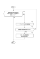
図7は、搬送車Vの車載コントローラ50の動作の一例を示すフローチャートである。図7に示すように、車載コントローラ50の判定部56は、通信システムCSによる他の機器との無線通信の通信品質が所定値未満である状態が一定時間以上継続したか否かの判定を行う(ステップS11)。ステップS11において、判定部56は、例えば所定時間ごとに通信部52において入出力される電波信号の強度を取得し、この電波信号の強度に基づいて判定を行ってもよい。判定部56により通信品質が所定値未満である状態が一定時間以上継続していない場合(ステップS11のNO)、他の機器との間で適切な無線通信が確立されているとして、処理を終了する。
FIG. 7 is a flowchart showing an example of the operation of the on-
一方、判定部56により通信品質が所定値未満である状態が一定時間以上継続したと判定された場合(ステップS11のYES)、他の機器との間で無線通信を行うための通信品質(電波強度)が十分ではないとして、アンテナ19を所定量回動させる(ステップS12)。ステップS12において、車載コントローラ50は、回動駆動部12を駆動させてフレーム部W及びアンテナ19を鉛直軸AX1の軸まわりに回動させる。車載コントローラ50は、回動駆動部12を所定速度で回動させてもよいし、所定角度ごとにステップ移動させてもよい。アンテナ19は、既存の移載部18(回動駆動部12)を用いることで位置を変えることができる。
On the other hand, if the
続いて、判定部56は、アンテナ19の回動量が設定値を超えるか否かを判定する(ステップS13)。ステップS13において、判定部56は、アンテナ19の回動量が、予め設定された回動量を超えるか否かを判定する。判定部56は、例えば、アンテナ19の回動量が設定地である360°を超えたか否かを判定する。判定部56により、アンテナ19の回動量が設定値を超えないと判定された場合(ステップS13のNO)、ステップS11以降の処理を繰り返し行う。すなわち、判定部56は、ステップS11において、アンテナ19の回動中において取得した通信品質について、所定値未満である状態が一定時間以上継続したか否かを判定する。
Subsequently, the determining
また、車載コントローラ50は、通信品質について、所定値未満である状態が一定時間以上継続しないアンテナ19の位置(電波強度が所定値以上となったアンテナ19の位置)を保持する。そして、搬送車V(図8に示す搬送車V1)は、上位コントローラHC又はブロッキングコントローラBCとの間で情報の伝達が可能となり、搬送指令の実行を再開することが可能となる。なお、このステップS11において、再度判定部56により、アンテナ19の回動量が設定値を超えないと判定された場合(ステップS13のNO)、ステップS12以降の処理が行われる。
In addition, the on-
また、判定部56により、アンテナ19の回動量が設定値を超えたと判定された場合(ステップS13のYES)、車載コントローラ50は、エラー又は警報等の異常処理を実行して(ステップS14)、処理を終了する。ステップS14において、車載コントローラ50は、異常処理として、エラー又は警報に代えて、例えば通信チャンネルの変更等、他の処理(対処)を実行させてもよい。また、車載コントローラ50は、このステップS14を行う前に、所定時間(例えば数分間)待機した後、再度ステップS11以降の処理を行ってもよい。例えば、図8に示す他の搬送車V2~V6のいずれかが、物品Mの移載動作を完了してグリッドセルCから既に進行している場合があり、この場合、搬送車V1において通信状況が改善されている可能性がある。また、上位コントローラHC又はブロッキングコントローラBCは、所定時間通信が行われていない搬送車V(図8の搬送車V1)を特定して、オペレータ等に通信不能の搬送車Vが存在することを通知してもよい。
Further, if the
図9は、実施形態に係る搬送車の他の例を示す斜視図である。図9に示す搬送車VAでは、アンテナ19の鉛直方向の位置を変更可能な構成となっている。なお、搬送車VAの他の構成については、上記した搬送車Vと同様であり、同じ符号を付して説明を省略する。図9に示す形態では、アンテナ19の位置が鉛直方向の下方に変更可能である。図9に示すように、アンテナ19は、鉛直軸AX1を中心とした回動と、鉛直方向への直線移動とを組み合わせた移動が可能となっており、アンテナ19の位置をより広範に移動させることができる。また、アンテナ19の下方への位置の変更は、簡易的なアクチュエータにより実行でき、コストの大幅な増加を抑えることができる。また、アンテナ19の位置をロック機構により保持しておき、例えばアンテナ19の回動に同期させてアンテナ19の保持を解放することでアンテナ19を自重により下降させる構成が適用されてもよい。
FIG. 9 is a perspective view showing another example of the transport vehicle according to the embodiment. The carrier VA shown in FIG. 9 has a configuration in which the vertical position of the
このように、本実施形態によれば、搬送車Vにおいてアンテナ19を駆動する機構を別に設けることなく、既存の移載部18の中の駆動機構を用いることでアンテナ19の位置及び姿勢の少なくとも一方を変更させることができる。そして、搬送車V(走行部20)自体は停止したままでも、アンテナ19による通信状態の改善を図ることができ、かつ、搬送車Vの大型化及び重量の増加を抑制することができる。
As described above, according to the present embodiment, at least the position and orientation of the
以上、本発明の実施形態について説明したが、本発明の技術的範囲は、上記した実施形態に限定されない。上記した実施形態に、多様な変更又は改良を加えることが可能であることは当業者において明らかである。また、変更又は改良を加えた形態も本発明の技術的範囲に含まれる。上記した実施形態等で説明した要件の1つ以上は、省略されることがある。また、上記した実施形態等で説明した要件は、適宜組み合わせることができる。また、本実施形態において示した各処理の実行順序は、前の処理の出力を後の処理で用いない限り、任意の順序で実現可能である。また、上記した実施形態における動作に関して、便宜上「まず」、「次に」、「続いて」等を用いて説明したとしても、この順序で実施することが必須ではない。また、法令で許容される限りにおいて、日本特許出願である特願2019-114535、及び上述の実施形態などで引用した全ての文献の開示を援用して本文の記載の一部とする。 Although the embodiments of the present invention have been described above, the technical scope of the present invention is not limited to the above-described embodiments. It will be apparent to those skilled in the art that various changes or improvements can be made to the embodiments described above. Furthermore, forms with changes or improvements are also included within the technical scope of the present invention. One or more of the requirements described in the above embodiments may be omitted. Furthermore, the requirements described in the above-described embodiments and the like can be combined as appropriate. Moreover, the execution order of each process shown in this embodiment can be realized in any order as long as the output of the previous process is not used in the subsequent process. Further, even if the operations in the above-described embodiments are described using "first", "next", "successively", etc. for convenience, it is not essential that they be performed in this order. In addition, to the extent permitted by law, the disclosures of Japanese Patent Application No. 2019-114535, which is a Japanese patent application, and all documents cited in the above-mentioned embodiments are incorporated into the description of the main text.
また、上記した実施形態では、アンテナ19を回動させることでアンテナ19の位置を変更すると説明しているが、アンテナ19の位置の変更は、アンテナ19の姿勢を変更することを含む意味で用いている。
Further, in the above-described embodiment, it is explained that the position of the
また、上記した実施形態では、アンテナ19がフレーム部Wの下端に取り付けられる形態を例に挙げて説明しているが、この形態に限定されない。例えば、アンテナ19は、フレーム部Wの外側上部において、水平方向(例えば、平面視でフレーム部Wの外周の接線方向など)に突出させた状態で設けられてもよい。
Further, in the above-described embodiment, the
また、上記した実施形態では、アンテナ19が鉛直方向(Z方向)に沿って配置される形態を例に挙げて説明しているが、この形態に限定されない。例えば、アンテナ19は、鉛直方向に対して傾けた状態でフレーム部Wに取り付けられてもよい。
Further, in the above-described embodiment, the
C・・・グリッドセル(マス目)
M・・・物品
R・・・軌道
BC・・・ブロッキングコントローラ(コントローラ)
HC・・・上位コントローラ(コントローラ)
V、V1~V6・・・搬送車
W・・・フレーム部
AP・・・アクセスポイント
AX1・・・鉛直軸
SYS・・・搬送車システム
10・・・本体部
11・・・ラテラル機構
12・・・回動駆動部
13・・・保持部
18・・・移載部
19、19A、19B・・・アンテナ
20・・・走行部
50・・・車載コントローラ
51・・・記憶部
52・・・通信部
53・・・走行制御部
54・・・移載制御部
55・・・進行許可生成部
56・・・判定部
57・・・状態情報処理部
C...Grid cell (square)
M...Article R...Trajectory BC...Blocking controller (controller)
HC...Upper controller (controller)
V, V1 to V6...Transport vehicle W...Frame portion AP...Access point AX1...Vertical axis SYS...
Claims (4)
前記走行部に取り付けられ、移載先に対して物品を受け渡しする移載部と、
前記移載部の動作に追従して位置及び姿勢の少なくとも一方が変更可能に設けられ、他の機器との間で無線通信を行うアンテナと、
前記移載部を囲むフレーム部と、
前記移載部及び前記フレーム部を鉛直軸まわりに回動させる回動駆動部と、を備え、
前記回動駆動部は、平面視において前記走行部に対する位置が変わるように前記フレーム部を回動させ、
前記アンテナは、前記フレーム部に設けられ、平面視において前記走行部に対する前記フレーム部の位置が変わることにより、前記鉛直軸まわりの位置が変更され、
前記回動駆動部によって前記フレーム部及び前記アンテナが移動する範囲は、平面視において、前記軌道における格子の1つのマス目に収まる、搬送車。 A running part that runs on a grid-like track ,
a transfer unit that is attached to the traveling unit and delivers the article to the transfer destination;
an antenna that is provided so that at least one of its position and orientation can be changed in accordance with the operation of the transfer unit, and that performs wireless communication with other devices;
a frame portion surrounding the transfer portion;
A rotation drive unit that rotates the transfer unit and the frame unit around a vertical axis,
The rotation driving section rotates the frame section so that the position relative to the running section changes in a plan view,
The antenna is provided in the frame part, and the position around the vertical axis is changed by changing the position of the frame part with respect to the running part in plan view ,
In the carrier vehicle, a range in which the frame portion and the antenna are moved by the rotation drive portion falls within one square of a lattice on the trajectory in plan view .
前記回動駆動部は、前記ラテラル機構を前記鉛直軸まわりに回動させ、
前記アンテナは、前記移載部において前記ラテラル機構により前記水平方向に移動する部分以外の部分に設けられる、請求項1に記載の搬送車。 The transfer unit includes a lateral mechanism that horizontally moves a holding unit that holds the article,
The rotation drive unit rotates the lateral mechanism around the vertical axis,
The conveyance vehicle according to claim 1, wherein the antenna is provided in a part of the transfer section other than a part moved in the horizontal direction by the lateral mechanism.
Applications Claiming Priority (3)
| Application Number | Priority Date | Filing Date | Title |
|---|---|---|---|
| JP2019114535 | 2019-06-20 | ||
| JP2019114535 | 2019-06-20 | ||
| PCT/JP2020/018612 WO2020255577A1 (en) | 2019-06-20 | 2020-05-08 | Conveyance vehicle |
Publications (3)
| Publication Number | Publication Date |
|---|---|
| JPWO2020255577A1 JPWO2020255577A1 (en) | 2020-12-24 |
| JPWO2020255577A5 JPWO2020255577A5 (en) | 2022-03-10 |
| JP7435605B2 true JP7435605B2 (en) | 2024-02-21 |
Family
ID=74037229
Family Applications (1)
| Application Number | Title | Priority Date | Filing Date |
|---|---|---|---|
| JP2021527439A Active JP7435605B2 (en) | 2019-06-20 | 2020-05-08 | Transport vehicle |
Country Status (7)
| Country | Link |
|---|---|
| US (1) | US20220359251A1 (en) |
| EP (1) | EP3988474A4 (en) |
| JP (1) | JP7435605B2 (en) |
| KR (1) | KR20220008331A (en) |
| CN (1) | CN114126988B (en) |
| IL (1) | IL289059A (en) |
| WO (1) | WO2020255577A1 (en) |
Families Citing this family (1)
| Publication number | Priority date | Publication date | Assignee | Title |
|---|---|---|---|---|
| JP2024509221A (en) | 2022-01-20 | 2024-02-29 | エルジー エナジー ソリューション リミテッド | Binder composition for manufacturing a positive electrode of a lithium secondary battery, and a positive electrode of a lithium secondary battery manufactured using the same |
Citations (5)
| Publication number | Priority date | Publication date | Assignee | Title |
|---|---|---|---|---|
| JP2715130B2 (en) | 1989-01-12 | 1998-02-18 | 株式会社ダイフク | Load transfer equipment |
| JP2005001804A (en) | 2003-06-11 | 2005-01-06 | Hitachi Ltd | Automatic crane system and method for controlling crane |
| JP2016175506A (en) | 2015-03-19 | 2016-10-06 | 村田機械株式会社 | Conveyance truck and conveyance truck system |
| JP2018118809A (en) | 2017-01-23 | 2018-08-02 | 株式会社ダイフク | Article conveying vehicle |
| JP6946965B2 (en) | 2017-11-22 | 2021-10-13 | 村田機械株式会社 | Transport system |
Family Cites Families (20)
| Publication number | Priority date | Publication date | Assignee | Title |
|---|---|---|---|---|
| JPS6041234B2 (en) * | 1976-08-20 | 1985-09-14 | 株式会社 山口機械研究所 | Power generation device using water flow |
| JPS58152235A (en) * | 1982-03-08 | 1983-09-09 | Fuji Photo Film Co Ltd | Photosensitive silver halide material |
| JPS6013801A (en) | 1983-07-01 | 1985-01-24 | Seiko Instr & Electronics Ltd | Device for purifying and concentrating high polymer substance |
| JPH09289708A (en) * | 1996-04-19 | 1997-11-04 | Toyota Autom Loom Works Ltd | Communication method for mover operation system |
| JPH09295707A (en) * | 1996-05-07 | 1997-11-18 | Shinko Electric Co Ltd | Management method for carrying object using carrier robot in clean room |
| JP2002068481A (en) * | 2000-08-28 | 2002-03-08 | Ishikawajima Harima Heavy Ind Co Ltd | Container stacking and storing device |
| JP4651835B2 (en) * | 2001-03-08 | 2011-03-16 | 株式会社シンク・ラボラトリー | How to store and take out pre-made rolls in roll three-dimensional warehouse |
| JP2003150247A (en) * | 2001-11-19 | 2003-05-23 | Murata Mach Ltd | Track carrier system |
| JP2004010204A (en) * | 2002-06-04 | 2004-01-15 | Matsushita Electric Ind Co Ltd | Marker system |
| JP4131706B2 (en) * | 2004-02-12 | 2008-08-13 | 日本輸送機株式会社 | Travel stop control device for automatic guided vehicles |
| CN101183431A (en) * | 2006-06-09 | 2008-05-21 | 日本电气株式会社 | Wireless communication system and wireless communication method |
| JP5266683B2 (en) * | 2007-08-03 | 2013-08-21 | 村田機械株式会社 | Transport system and teaching method in the transport system |
| JP5450334B2 (en) * | 2010-09-28 | 2014-03-26 | 株式会社椿本チエイン | Goods management system |
| DE202013008718U1 (en) * | 2013-09-30 | 2013-12-19 | Grenzebach Maschinenbau Gmbh | Transport vehicle for the trouble-free transport of load racks in factory halls with radio shading and with partially autonomous driving |
| DE102013019368A1 (en) * | 2013-11-18 | 2015-05-21 | Grenzebach Maschinenbau Gmbh | Method and device for the largely automated assembly of goods deliveries in warehouses |
| JP6365136B2 (en) * | 2014-09-02 | 2018-08-01 | 村田機械株式会社 | Traveling vehicle system |
| JP2017154840A (en) * | 2016-02-29 | 2017-09-07 | 株式会社ダイフク | Article conveyance facility |
| JP6520797B2 (en) * | 2016-04-11 | 2019-05-29 | 株式会社ダイフク | Goods transport equipment |
| JP7066160B2 (en) * | 2017-08-23 | 2022-05-13 | 学校法人千葉工業大学 | Self-propelled rebar work robot, self-propelled rebar binding robot |
| DE102017222883A1 (en) | 2017-12-15 | 2019-06-19 | Te Connectivity Germany Gmbh | Contacting unit for electrically contacting at least one electronic segment of an electronic module and method |
-
2020
- 2020-05-08 CN CN202080044041.4A patent/CN114126988B/en active Active
- 2020-05-08 WO PCT/JP2020/018612 patent/WO2020255577A1/en active Application Filing
- 2020-05-08 KR KR1020217040980A patent/KR20220008331A/en not_active Application Discontinuation
- 2020-05-08 JP JP2021527439A patent/JP7435605B2/en active Active
- 2020-05-08 US US17/620,967 patent/US20220359251A1/en active Pending
- 2020-05-08 EP EP20827173.4A patent/EP3988474A4/en active Pending
-
2021
- 2021-12-16 IL IL289059A patent/IL289059A/en unknown
Patent Citations (5)
| Publication number | Priority date | Publication date | Assignee | Title |
|---|---|---|---|---|
| JP2715130B2 (en) | 1989-01-12 | 1998-02-18 | 株式会社ダイフク | Load transfer equipment |
| JP2005001804A (en) | 2003-06-11 | 2005-01-06 | Hitachi Ltd | Automatic crane system and method for controlling crane |
| JP2016175506A (en) | 2015-03-19 | 2016-10-06 | 村田機械株式会社 | Conveyance truck and conveyance truck system |
| JP2018118809A (en) | 2017-01-23 | 2018-08-02 | 株式会社ダイフク | Article conveying vehicle |
| JP6946965B2 (en) | 2017-11-22 | 2021-10-13 | 村田機械株式会社 | Transport system |
Also Published As
| Publication number | Publication date |
|---|---|
| CN114126988B (en) | 2023-11-10 |
| KR20220008331A (en) | 2022-01-20 |
| IL289059A (en) | 2022-02-01 |
| TW202105111A (en) | 2021-02-01 |
| EP3988474A1 (en) | 2022-04-27 |
| JPWO2020255577A1 (en) | 2020-12-24 |
| WO2020255577A1 (en) | 2020-12-24 |
| EP3988474A4 (en) | 2023-06-21 |
| CN114126988A (en) | 2022-03-01 |
| US20220359251A1 (en) | 2022-11-10 |
Similar Documents
| Publication | Publication Date | Title |
|---|---|---|
| TWI505980B (en) | Transfer system | |
| WO2017029871A1 (en) | Conveyance system | |
| CN113056405A (en) | Overhead transport vehicle and overhead transport vehicle system | |
| JP7351348B2 (en) | Conveyance system and grid system | |
| JP7435605B2 (en) | Transport vehicle | |
| JP7226537B2 (en) | Driving vehicle system and driving vehicle control method | |
| WO2021220582A1 (en) | Overhead carrier and overhead carrying system | |
| CN114080364B (en) | Traveling vehicle system and method for controlling traveling vehicle | |
| TWI830922B (en) | moving vehicle | |
| JP7235106B2 (en) | Driving vehicle system and driving vehicle control method | |
| CN112173981A (en) | Conveyor control device and conveyor control system including the same | |
| CN113841099B (en) | Traveling vehicle system and method for controlling traveling vehicle | |
| JP7347695B2 (en) | ceiling storage system | |
| WO2023188769A1 (en) | Conveyance system | |
| WO2023026512A1 (en) | Conveyance system | |
| WO2024070299A1 (en) | Overhead conveyance vehicle | |
| WO2024070303A1 (en) | Overhead conveyance vehicle | |
| TW202329312A (en) | Transfer system | |
| KR20230067513A (en) | Article transport apparatus | |
| KR20240051991A (en) | return system | |
| CN115427329A (en) | Transport vehicle system |
Legal Events
| Date | Code | Title | Description |
|---|---|---|---|
| A521 | Request for written amendment filed |
Free format text: JAPANESE INTERMEDIATE CODE: A523 Effective date: 20211213 |
|
| A621 | Written request for application examination |
Free format text: JAPANESE INTERMEDIATE CODE: A621 Effective date: 20211213 |
|
| A131 | Notification of reasons for refusal |
Free format text: JAPANESE INTERMEDIATE CODE: A131 Effective date: 20230228 |
|
| A521 | Request for written amendment filed |
Free format text: JAPANESE INTERMEDIATE CODE: A523 Effective date: 20230419 |
|
| A131 | Notification of reasons for refusal |
Free format text: JAPANESE INTERMEDIATE CODE: A131 Effective date: 20230808 |
|
| A521 | Request for written amendment filed |
Free format text: JAPANESE INTERMEDIATE CODE: A523 Effective date: 20231005 |
|
| TRDD | Decision of grant or rejection written | ||
| A01 | Written decision to grant a patent or to grant a registration (utility model) |
Free format text: JAPANESE INTERMEDIATE CODE: A01 Effective date: 20240109 |
|
| A61 | First payment of annual fees (during grant procedure) |
Free format text: JAPANESE INTERMEDIATE CODE: A61 Effective date: 20240122 |
|
| R150 | Certificate of patent or registration of utility model |
Ref document number: 7435605 Country of ref document: JP Free format text: JAPANESE INTERMEDIATE CODE: R150 |