JP7435498B2 - worn airbag device - Google Patents
worn airbag device Download PDFInfo
- Publication number
- JP7435498B2 JP7435498B2 JP2021017574A JP2021017574A JP7435498B2 JP 7435498 B2 JP7435498 B2 JP 7435498B2 JP 2021017574 A JP2021017574 A JP 2021017574A JP 2021017574 A JP2021017574 A JP 2021017574A JP 7435498 B2 JP7435498 B2 JP 7435498B2
- Authority
- JP
- Japan
- Prior art keywords
- protected
- bag
- person
- inflation
- inner bag
- Prior art date
- Legal status (The legal status is an assumption and is not a legal conclusion. Google has not performed a legal analysis and makes no representation as to the accuracy of the status listed.)
- Active
Links
- 230000001681 protective effect Effects 0.000 claims description 35
- 230000001012 protector Effects 0.000 claims description 5
- 239000004744 fabric Substances 0.000 description 6
- 230000002093 peripheral effect Effects 0.000 description 6
- 230000001133 acceleration Effects 0.000 description 4
- 230000004913 activation Effects 0.000 description 3
- CURLTUGMZLYLDI-UHFFFAOYSA-N Carbon dioxide Chemical compound O=C=O CURLTUGMZLYLDI-UHFFFAOYSA-N 0.000 description 2
- 238000013459 approach Methods 0.000 description 2
- 238000003780 insertion Methods 0.000 description 2
- 230000037431 insertion Effects 0.000 description 2
- 230000002035 prolonged effect Effects 0.000 description 2
- 210000000689 upper leg Anatomy 0.000 description 2
- XLYOFNOQVPJJNP-UHFFFAOYSA-N water Substances O XLYOFNOQVPJJNP-UHFFFAOYSA-N 0.000 description 2
- 210000001217 buttock Anatomy 0.000 description 1
- 229910002092 carbon dioxide Inorganic materials 0.000 description 1
- 239000001569 carbon dioxide Substances 0.000 description 1
- 238000007599 discharging Methods 0.000 description 1
- WABPQHHGFIMREM-UHFFFAOYSA-N lead(0) Chemical compound [Pb] WABPQHHGFIMREM-UHFFFAOYSA-N 0.000 description 1
- 239000000463 material Substances 0.000 description 1
- 229920000728 polyester Polymers 0.000 description 1
- 238000009958 sewing Methods 0.000 description 1
- 239000012209 synthetic fiber Substances 0.000 description 1
- 229920002994 synthetic fiber Polymers 0.000 description 1
- 239000002759 woven fabric Substances 0.000 description 1
Images


Classifications
-
- A—HUMAN NECESSITIES
- A41—WEARING APPAREL
- A41D—OUTERWEAR; PROTECTIVE GARMENTS; ACCESSORIES
- A41D13/00—Professional, industrial or sporting protective garments, e.g. surgeons' gowns or garments protecting against blows or punches
- A41D13/05—Professional, industrial or sporting protective garments, e.g. surgeons' gowns or garments protecting against blows or punches protecting only a particular body part
- A41D13/0506—Hip
-
- A—HUMAN NECESSITIES
- A41—WEARING APPAREL
- A41D—OUTERWEAR; PROTECTIVE GARMENTS; ACCESSORIES
- A41D13/00—Professional, industrial or sporting protective garments, e.g. surgeons' gowns or garments protecting against blows or punches
- A41D13/015—Professional, industrial or sporting protective garments, e.g. surgeons' gowns or garments protecting against blows or punches with shock-absorbing means
- A41D13/018—Professional, industrial or sporting protective garments, e.g. surgeons' gowns or garments protecting against blows or punches with shock-absorbing means inflatable automatically
-
- A—HUMAN NECESSITIES
- A41—WEARING APPAREL
- A41D—OUTERWEAR; PROTECTIVE GARMENTS; ACCESSORIES
- A41D13/00—Professional, industrial or sporting protective garments, e.g. surgeons' gowns or garments protecting against blows or punches
- A41D13/05—Professional, industrial or sporting protective garments, e.g. surgeons' gowns or garments protecting against blows or punches protecting only a particular body part
Description
本発明は、保護対象者に装着させて、保護対象者の転倒時等に、膨張させたエアバッグの膨張部位により、保護対象者の保護対象部位を保護する着用エアバッグ装置に関する。 The present invention relates to a wearable airbag device that is attached to a person to be protected and protects the part of the person to be protected by the inflated portion of the inflated airbag when the person falls.
従来、着用エアバッグ装置としては、着用した保護対象者(例えば、高齢者)の転倒時、加速度センサ等により、転倒を検知して、ガス発生器から吐出した膨張用ガスにより膨張した所定位置の各エアバッグが、それぞれ、保護対象者の保護対象部位である臀部や腰部、あるいは、頭部やその左右の側部、を覆うものが知られている(例えば、特許文献1参照)。また、ガス発生器からの膨張用ガスを流入させて1つのエアバッグを膨張させて、保護対象者の保護対象部位としての腰部の周囲を囲むように、覆うものもあった(例えば、特許文献2参照)。 Conventionally, wearable airbag devices use an acceleration sensor or the like to detect the fall of a person to be protected (e.g., an elderly person) using an acceleration sensor, and then deploy an airbag at a predetermined position that is inflated by inflation gas discharged from a gas generator. It is known that each airbag covers the buttock or lower back, or the head or the left and right sides of the protectee (for example, see Patent Document 1). In addition, some airbags were inflated by inflating gas from a gas generator to surround the lower back of the person being protected (for example, Patent Document (see 2).
しかし、従来の着用エアバッグ装置では、ガス発生器から吐出される膨張用ガスがエアバッグ内でどのように流れるかに関しては、具体的ではなく、保護対象者に向かって膨張用ガスが吐出されれば、膨張用ガスが不必要に保護対象者を押圧したり、あるいは、その反動として、保護対象部位を覆う膨張部位が、保護対象者から浮き上がり、迅速に、保護対象部位に配置させ難くなったりする事態を招いてしまう。 However, in conventional wearable airbag devices, there is no specificity regarding how the inflation gas discharged from the gas generator flows within the airbag, and the inflation gas is discharged toward the protected person. If so, the inflation gas may unnecessarily press the person to be protected, or as a reaction, the inflatable part that covers the part to be protected will lift away from the person to be protected, making it difficult to quickly place it on the part to be protected. This may lead to a situation where
本発明は、上述の課題を解決するものであり、作動時の膨張用ガスの流れを安定させて、的確に保護対象部位を覆えるように、安定したエアバッグの膨張挙動を確保できる着用エアバッグ装置を提供することを目的とする。 The present invention solves the above-mentioned problems, and provides a wearable air bag that can stabilize the flow of inflation gas during activation and ensure stable inflation behavior of the airbag so as to accurately cover the area to be protected. The purpose is to provide a bag device.
本発明に係る着用エアバッグ装置では、保護対象者に装着されて、ガス発生器からの膨張用ガスによって膨張し、保護対象者の保護対象部位を保護するエアバッグ、を備えて構成される着用エアバッグ装置であって、
前記エアバッグが、
保護対象者側の内側壁部と保護対象者から離れる側の外側壁部とを具備してなる外周壁を構成するとともに、膨張完了時に前記保護対象部位を覆う保護膨張部を有したバッグ本体と、
該バッグ本体内に配設されて、前記ガス発生器からの膨張用ガスにより膨張するとともに、前記バッグ本体を膨張させるように、前記バッグ本体への膨張用ガスの供給用の供給口を有したインナバッグと、
を備えて構成され、
前記インナバッグの前記供給口が、前記バッグ本体側へ供給する膨張用ガスを、前記保護膨張部側に向き、かつ、前記外側壁部側に向けて、流すように、配設されていることを特徴とする。
The wearable airbag device according to the present invention includes an airbag that is attached to a person to be protected and is inflated by an inflation gas from a gas generator to protect the part of the person to be protected. An airbag device,
The airbag is
A bag main body having an outer circumferential wall comprising an inner wall portion on the side of the person to be protected and an outer wall portion on the side away from the person to be protected, and a protective inflatable portion that covers the part to be protected when inflation is completed; ,
The bag has a supply port for supplying inflation gas to the bag body so as to be disposed within the bag body and to be inflated by the inflation gas from the gas generator and to inflate the bag body. Inner bag and
configured with
The supply port of the inner bag is arranged so that the inflation gas supplied to the bag body side flows toward the protective inflation section and toward the outer wall section. It is characterized by
本発明に係る着用エアバッグ装置では、作動時、ガス発生器から膨張用ガスが吐出されれば、膨張用ガスによって、バッグ本体内のインナバッグが膨張し、そして、インナバッグの供給口を経て、バッグ本体内に、膨張用ガスが流入して、バッグ本体が膨張する。この時、インナバッグからバッグ本体に流出する膨張用ガスは、保護膨張部側に向き、かつ、外側壁部側に向けて、流れることから、保護対象者側を不必要に押圧せずに、円滑に、保護膨張部側に流れて、迅速かつ的確に、保護膨張部を、保護対象部位を保護可能に覆えるように、膨張させることができる。さらに、保護膨張部を膨張させる膨張用ガスは、膨張するインナバッグの供給口から供給されることから、インナバッグが膨張を完了させれば、供給口の開口面が所定位置で安定して配置されることとなって、流れ方向を一定として、バッグ本体内に供給されて、バッグ本体の膨張挙動を安定させることができる。 In the wearable airbag device according to the present invention, when the inflation gas is discharged from the gas generator during operation, the inner bag inside the bag body is inflated by the inflation gas, and then the inner bag is inflated through the supply port of the inner bag. , the inflation gas flows into the bag body and the bag body is inflated. At this time, the inflation gas flowing out from the inner bag into the bag body flows toward the protective inflation section and toward the outer wall, so that it does not unnecessarily press the person being protected. It can smoothly flow toward the protective inflatable part and quickly and accurately inflate the protective inflatable part so as to protectably cover the area to be protected. Furthermore, since the inflation gas that inflates the protective inflation section is supplied from the supply port of the inner bag that is being inflated, once the inner bag has completed inflation, the opening surface of the supply port will be stably positioned at the predetermined position. As a result, it can be supplied into the bag body with the flow direction constant, and the inflation behavior of the bag body can be stabilized.
したがって、本発明に係る着用エアバッグ装置では、作動時の膨張用ガスの流れを安定させて、的確に保護対象部位を覆えるように、安定したエアバッグの膨張挙動を確保できる。 Therefore, in the wearable airbag device according to the present invention, the flow of inflation gas during activation is stabilized, and stable inflation behavior of the airbag can be ensured so that the area to be protected can be accurately covered.
そして、本発明に係る着用エアバッグ装置では、前記インナバッグの前記供給口が、前記バッグ本体側へ供給する膨張用ガスを、前記バッグ本体の前記内側壁部と前記外側壁部との対向方向と斜め交差する方向に向けて、流すように、配設されていることが望ましい。 In the wearable airbag device according to the present invention, the supply port of the inner bag supplies inflation gas to the bag main body in a direction opposite to the inner wall and the outer wall of the bag main body. It is desirable that the water be installed so that it flows in a direction that intersects diagonally with the water.
このような構成では、インナバッグからバッグ本体内に供給される膨張用ガスが、保護対象者側に向かわずに、外側壁部における保護膨張部の先端側に向かうように流れることとなって、好適に、保護対象者への押圧抑制と、迅速な保護膨張部の膨張完了と、を確保できる。 In such a configuration, the inflation gas supplied from the inner bag into the bag body flows not toward the person to be protected, but toward the distal end of the protective inflation section on the outer wall. Preferably, it is possible to suppress pressure on the person to be protected and quickly complete inflation of the protective inflation section.
また、本発明に係る着用エアバッグ装置では、膨張完了時の前記バッグ本体が、保護対象者の腰部における左右の大腿骨転子部付近を覆うように、前記保護膨張部を、腰保護部として、左右両側に配設させるとともに、保護対象者の背面側における左右両側の前記腰保護部の間の上縁側に、左右両側の前記腰保護部と連通する連通部を配設させる構成として、
前記インナバッグが、
前記連通部内に配設される中央部と、該中央部から左右両側に延びて、左右の前記腰保護部の上縁側に配設される左側部及び右側部と、を備えて構成されるとともに、
前記中央部に、前記ガス発生器からの膨張用ガスを流入させ、前記左側部と前記右側部との先端側に、それぞれ、前記供給口を配設させていることを特徴とする。
Further, in the wearable airbag device according to the present invention, the protective inflation section is configured as a waist protection section so that the bag body when inflation is completed covers the vicinity of the right and left femoral trochanteric regions in the waist region of the person to be protected. , is arranged on both the left and right sides, and a communication part that communicates with the waist protection parts on both the left and right sides is arranged on the upper edge side between the waist protection parts on both the left and right sides on the back side of the person to be protected,
The inner bag is
The device includes a central portion disposed within the communication portion, and left and right portions extending from the central portion to both left and right sides and disposed on the upper edge sides of the left and right lower back protection portions, and ,
The inflation gas from the gas generator is allowed to flow into the center portion, and the supply ports are provided at the tip sides of the left side portion and the right side portion, respectively.
このような構成では、作動時、バッグ本体の左右の各腰保護部が膨張すれば、保護対象者の左右の大腿骨転子部を覆うことができる。保護膨張部としての腰保護部が保護する大腿骨転子部は、骨折等すれば治療が長引くこととなる部位であり、着用エアバッグ装置のバッグ本体が、このような部位を保護できれば、高齢者の保護対象者が転倒しても、好適に、大腿骨転子部を保護できる。また、バッグ本体に膨張用ガスを供給する供給口を備えたインナバッグは、それぞれ供給口を備えた左側部と右側部との間の中央部を、ガス発生器からの膨張用ガスの流入部位として、バッグ本体における左右の腰保護部の間の連通部に配設されており、着用エアバッグ装置の作動時、インナバッグの中央部から左側部と右側部とに均等に膨張用ガスを流すことができ、そのため、左側部と右側部との供給口から膨張用ガスを流入させて、バッグ本体は、左右の腰保護部を迅速かつ均等に膨張させることができる。 With such a configuration, when the left and right waist protection parts of the bag main body are inflated during operation, the right and left femoral trochanteric parts of the person to be protected can be covered. The trochanteric part of the femur, which is protected by the lower back protection part as a protective inflation part, is a part where the treatment would be prolonged if there is a fracture.If the bag body of the wearable airbag device could protect this part, Even if the person to be protected falls down, the trochanteric part of the femur can be suitably protected. In addition, in an inner bag equipped with a supply port for supplying inflation gas to the bag body, the central part between the left side and the right side, each equipped with a supply port, is the inflow area of the inflation gas from the gas generator. It is placed in the communication area between the left and right waist protection parts of the bag body, and when the wearable airbag device is activated, the inflation gas flows evenly from the center of the inner bag to the left and right sides. Therefore, by allowing inflation gas to flow in from the supply ports on the left and right sides, the bag main body can quickly and evenly inflate the left and right waist protection parts.
この場合、膨張完了時の前記バッグ本体が、前記連通部から上方に延びて、保護対象者の背面側の左右方向の中央付近で、上下方向に延びる縦膨張部を備えるとともに、該縦膨張部の上端側に、前記保護膨張部の他の部位としての保護対象者の頭部の後面側を覆う頭保護部を備えて構成され、
前記インナバッグが、前記縦膨張部内に配設されるように、前記中央部から上方に延び、延びた上端側に、前記供給口を配設させていてもよい。
In this case, the bag main body when inflation is completed includes a vertically inflatable part that extends upward from the communication part and extends in the vertical direction near the center in the left-right direction on the back side of the person to be protected, and the vertically inflatable part A head protection part that covers the rear side of the head of the person to be protected as another part of the protective expansion part is provided on the upper end side,
The inner bag may extend upward from the central portion, and the supply port may be disposed on the extended upper end side so that the inner bag is disposed within the vertical expansion portion.
このような構成では、膨張時のバッグ本体が、保護膨張部として、左右の腰保護部の他に、保護対象者の頭部を保護する頭保護部を備えていることから、後頭部を路面等に接触するように、高齢者等の保護対象者が転倒しても、後頭部を的確に保護できる。また、頭保護部は、バッグ本体の連通部から上方に延びる縦膨張部の上端側に配設されて、内部に、インナバッグの中央部から上方に延びた上端側の供給口を設けた部位を配設させており、インナバッグの供給口からの膨張用ガスを流入させて膨張する際、膨張用ガスは、外側壁部側で、かつ、頭保護部側に、斜め上向きに流れることから、不必要に、保護対象者の頭部を押圧せずに、迅速に、頭保護部を膨張させることができる。 In such a configuration, when the bag body is inflated, it is equipped with a head protection part that protects the head of the person to be protected, in addition to the left and right waist protection parts as a protective inflation part, so that the back of the head is protected from the road surface, etc. Even if a person to be protected, such as an elderly person, falls, the back of the head can be properly protected. Further, the head protection part is a part disposed at the upper end side of the vertical expansion part extending upward from the communication part of the bag body, and has a supply port provided therein at the upper end side extending upward from the center part of the inner bag. When the inner bag is inflated by inflation gas flowing from the supply port of the inner bag, the inflation gas flows diagonally upward toward the outer wall side and toward the head protection section. The head protection part can be quickly inflated without unnecessarily pressing the head of the person to be protected.
そして、このような頭保護部を有したバッグ本体は、左右の腰保護部を膨張させるような部位を配設させずに、頭保護部だけを有して構成されていてもよい。すなわち、膨張完了時の前記バッグ本体が、保護対象者の背面側の左右方向の中央付近で、上下方向に延びて膨張する縦膨張部を備えるとともに、該縦膨張部の上端側に、保護対象者の頭部の後面側を覆う前記保護膨張部としての頭保護部を備えて構成され、前記インナバッグが、前記縦膨張部内に配設されて、下端側に、前記ガス発生器からの膨張用ガスを流入させるように構成され、上端側に、前記供給口を配設させていてもよい。 A bag main body having such a head protection part may be configured to have only the head protection part without disposing a portion that inflates the left and right waist protection parts. That is, when the bag body is fully inflated, it has a vertically inflatable part that extends in the vertical direction and inflates near the center in the left-right direction on the back side of the person to be protected. The inner bag is configured to include a head protection part as the protection inflation part that covers the rear side of the head of a person, and the inner bag is disposed within the vertical inflation part, and the inner bag is provided with a head protection part as the protection inflation part that covers the rear side of the head of a person. The supply port may be arranged on the upper end side.
勿論、バッグ本体が、頭保護部を備えて構成されている場合には、インナバッグの上端側が、保護対象者における首部の後側の周囲を囲うように、横方向に延びる首囲繞部を備え、前記インナバッグの上端側の前記供給口が、複数として、前記首囲繞部に並設されていてもよい。 Of course, if the bag body is configured to include a head protection section, the upper end side of the inner bag may include a neck encircling section extending laterally so as to surround the back side of the neck of the person to be protected. A plurality of the supply ports on the upper end side of the inner bag may be arranged in parallel in the neck surrounding part.
このような構成では、バッグ本体の頭保護部が、インナバッグの上端側の首囲繞部に並設された供給口から供給される膨張用ガスにより、保護対象者の首部の後側の周囲から上方に延びるように膨張することから、保護対象者の頭部の後側を略半円筒状に覆うことができて、転倒時の保護対象者が回転し、頭部が横方向に旋回しても、略半円筒状の頭保護部により、路面等から頭部を円滑に保護することができる。そして勿論、インナバッグの首囲繞部に並設された複数の供給口から流出する膨張用ガスは、バッグ本体における外側壁部側に向け、かつ、頭保護部側に向いて流れ、すなわち、首部側から斜め上外向きに向けて流れることから、膨張する頭保護部は、頭部を押圧せず、かつ、迅速に、頭部の後側を略半円筒状に覆うように、膨張することができる。 In such a configuration, the head protection part of the bag body is inflated from around the back of the neck of the person to be protected by the inflation gas supplied from the supply port arranged in parallel to the neck surrounding part on the upper end side of the inner bag. Since it expands upward, it can cover the back side of the person's head in a roughly semi-cylindrical shape, allowing the person to rotate during a fall and the head to turn laterally. Also, the substantially semi-cylindrical head protection portion can smoothly protect the head from the road surface and the like. Of course, the inflation gas flowing out from the plurality of supply ports arranged in parallel in the neck circumference of the inner bag flows toward the outer wall of the bag body and toward the head protection section. Since it flows diagonally upward and outward from the side, the inflating head protection part can quickly expand to cover the back side of the head in a substantially semi-cylindrical shape without pressing the head. Can be done.
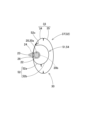
以下、本発明の実施形態を図面に基づいて説明すると、第1実施形態の着用エアバッグ装置10は、図1~5に示すように、作動時、着用する保護対象者(例えば、高齢者)1の腰部2における左右の大腿骨転子部3(L,R)を保護対象部位7として保護するように、エアバッグ30を膨張させるものである。この着用エアバッグ装置10は、ガス発生器20と、ガス発生器20からの膨張用ガスGにより膨張するエアバッグ30と、保護対象者1の転倒を検知するセンサ部18を備えてガス発生器20を作動させる作動制御装置17と、ガス発生器20、エアバッグ30、及び、作動制御装置17を保持して、保護対象者1に装着するベスト型の装着部材11と、を備えて構成されている。
Hereinafter, embodiments of the present invention will be described based on the drawings. As shown in FIGS. 1 to 5, the
装着部材11は、保護対象者1の上半身1aに装着可能なベストとして構成され、保護対象者1の上半身1aの正面を覆う左前部12及び右前部13を備えるとともに、保護対象者1の上半身1aの背面を覆う背面部14を備えて構成され、さらに、左前部12と右前部13との内側縁12a,13a相互を結合させるファスナー等の締結具16を備えて構成されている。
The mounting
作動制御装置17は、上下前後左右の3軸周りの角速度を検知可能な角速度センサと、上下前後左右の3軸方向の加速度を検知可能な加速度センサと、を有してなるセンサ部18を備えるとともに、センサ部18からの信号により、保護対象者1が通常動作と異なった転倒動作を行っていると検知されると、ガス発生器20を作動させるように構成されている。なお、具体的には、作動制御装置17は、センサ部18からの信号により、保護対象者1が通常動作と異なった転倒動作を開始していると、種々の閾値から判定可能な判定手段を備えて、判定手段の判定に基づいて、保護対象者1が転倒したと検出し、そして、ガス発生器20を作動させる。また、作動制御装置17には、センサ部18の作動用やガス発生器20の作動用信号の出力用に、図示しない電池等からなる電源も内蔵されている。
The
作動制御装置17は、装着部材11における背面部14の下部14a側に、保護対象者1の衣服等と接触しないように、図示しないカバー布等に覆われて、取り付けられている。
The
ガス発生器20は、図2,4,5に示すように、内部に圧縮された二酸化炭素等からなる膨張用ガスGを貯留した略円柱状の本体部20aと、本体部20aの外周面側に開口された2つのガス吐出口20bと、を備えて構成されている。ガス発生器20は、保護対象者1の転倒を検知した作動制御装置17の作動信号を入力して、本体部20a内に貯留した膨張用ガスGをガス吐出口20bから吐出する構成としている。実施形態のガス発生器20は、本体部20aを挟持する円筒状の取付ブラケット22を利用して、エアバッグ30に組み付けられている。取付ブラケット22は、取付ボルト23を突設させており、エアバッグ30の後述するインナバッグ51内に、本体部20aを挟持した状態で、収納されて、取付ボルト23を、インナバッグ51とエアバッグ30のバッグ本体32とを貫通させて、エアバッグ30から突出させ、さらに、取付板26に貫通させ、ナット24を締結させることにより、インナバッグ51とバッグ本体32とを、取付ブラケット22と取付板26とで挟持する状態として、ガス発生器20をエアバッグ30に取り付けている。取付ブラケット22は、ガス発生器20の本体部20aにおけるガス吐出口20bから外れた両端側に、配設されている。
As shown in FIGS. 2, 4, and 5, the
エアバッグ30は、膨張完了時に保護対象部位を覆う保護膨張部41を有したバッグ本体32と、バッグ本体32内に配設されて、ガス発生器20からの膨張用ガスGにより膨張するとともに、バッグ本体32を膨張させるように、バッグ本体32への膨張用ガスGの供給用の供給口59を有したインナバッグ51と、を備えて構成されている。
The
第1実施形態の場合、バッグ本体32とインナバッグ51とは、可撓性を有したポリエステル等の合成繊維からなる織布から形成されている。
In the case of the first embodiment, the
バッグ本体32は、保護対象者1側の内側壁部34と保護対象者1から離れる側の外側壁部35とを具備してなるエアバッグ30の外周壁33を構成するとともに、膨張完了時に保護対象者1の保護対象部位3(L,R)を覆う保護膨張部としての腰保護部41(L,R)を有して構成されている。バッグ本体32は、膨張完了形状として、左右両側に配設される略長方形板状の本体膨張部39(L,R)と、保護対象者1の背面側における左右の本体膨張部39(L,R)の上縁側相互を連結する略長方形板状の連通部37と、を備えて構成されている。そして、内側壁部34と外側壁部35とは、相互に、略同一の外形形状としており、内側壁部34は、左右の本体膨張部39(L,R)と連通部37との保護対象者1側となる壁部を構成して、外側壁部35は、左右の本体膨張部39(L,R)と連通部37との保護対象者1から離れた側となる壁部を構成している。
The
左右の本体膨張部39(L,R)は、それぞれ、下部側に、保護対象者1の腰部2における左右の大腿骨転子部3(L,R)付近を覆う保護膨張部としての腰保護部41(L,R)を配設させ、上縁39a側に、インナバッグ51の左右両端側を収納する縁側膨張部40(L,R)を配設させて構成されている。
The left and right main body expansion parts 39 (L, R) each have a lower back protection part on the lower side as a protective expansion part that covers the vicinity of the left and right femoral trochanteric parts 3 (L, R) in the
インナバッグ51は、エアバッグ30を平らに展開した状態での膨張完了形状を、左右方向に延びた円柱状として、左右方向の中央部54が、バッグ本体32内の連通部37内に収納されて、中央部54から左右両側に延びた左側部55と右側部57とが、それぞれ、バッグ本体32内の本体膨張部39(L,R)の上縁39a側の縁側膨張部40(L,R)内に収納されるように、配設されている。
The
そして、インナバッグ51の中央部54は、膨張用ガスの流入部位とするように、内部に、既述のガス発生器20が収納され、左側部55と右側部57とには、バッグ本体32側に膨張用ガスGを供給する供給口59(L,R)が開口されている。左右の供給口59(L,R)は、円形の開口形状として、円柱状に膨張した左側部55と右側部57とにおいて、その開口面と直交方向の向きを、斜め下の外向きに向くように、換言すれば、供給口59(L,R)からバッグ本体32内に流出する膨張用ガスGの流出方向GDを、保護膨張部としての腰保護部41(L,R)側に向き、かつ、外側壁部35側に向けて、流すように、詳しくは、バッグ本体32の内側壁部34と外側壁部35との対向方向(実施形態の場合、略水平方向)TDと略45°の角度θで斜め交差する下向き方向に向けて、配設されている(図3参照)。
The above-described
第1実施形態のインナバッグ51は、周壁52が、左右方向に延びた帯状の内側基布52aと外側基布52bの全周の周縁相互を縫合により結合させて形成されており、供給口59(L,R)は、外側基布52bの左右両端側の下部側に、開口されている。また、内側基布52aと外側基布52bの周縁相互の上縁側の結合部52cは、バッグ本体32の内側壁部34にも、結合されて、インナバッグ51が、バッグ本体32内で、位置ずれしないように、配設されている。
In the
なお、エアバッグ30は、バッグ本体32の上縁32aに、複数の取付タブ30aが取り付けられており、これらの取付タブ30aを、縫製等により、装着部材11の内側面側に取り付けて、装着部材11に保持される。また、エアバッグ30は、着用エアバッグ装置10の作動前の状態では、本体膨張部39の下縁39b側を、上縁39a側に接近させるように、折り畳まれて、装着部材11に保持される。
Note that the
第1実施形態の着用エアバッグ装置10では、ガス発生器20を収納した状態で、インナバッグ51を形成し、バッグ本体32の内側壁部34の所定位置にインナバッグ51を配置させて、結合部32cを内側壁部34に結合させるとともに、バッグ本体32の内側壁部34と外側壁部35とを、バッグ本体21の外表面側相互で合わせて、一部を残して重ねた外周縁相互を縫合等により形成し、残した未結合部の開口を利用して、バッグ本体32を反転させ、開口していた未結合部を結合させ、そして、バッグ本体32の上縁32a側に取付タブ30bを取付ければ、エアバッグ30を形成することができる。
In the
なお、ガス発生器20の本体部20aを挟持した取付ブラケット22の取付ボルト23は、インナバッグ51を内側壁部34に配置する際、内側壁部34を貫通させておき、エアバッグ30の形成後、取付板26に貫通させて、ナット24止めすれば、ガス発生器20をエアバッグ30に組み付けておくことができる。また、ガス発生器20を作動させる信号線は、インナバッグ51と内側壁部34とに設けた図示しない挿通孔から取り出しておく。そして、エアバッグ30の下縁39b側を上縁39a側に接近させるように折り畳んで、取付タブ30aを利用して、エアバッグ30を装着部材11に取り付けるとともに、予め、装着部材11に取り付けておいた作動制御装置17からの作動信号入力用の図示しないリード線をガス発生器20から延びた信号線と接続させれば、装着部材11にエアバッグ30やガス発生器20等を保持させた着用エアバッグ装置10を製造することができる。
Note that the mounting
第1実施形態の着用エアバッグ装置10では、締結具16を利用して、装着部材11を保護対象者1の上半身1aに装着し、その後、保護対象者1が転倒すると、センサ部18からの信号を入力していた作動制御装置17が、ガス発生器20を作動させて、ガス発生器20のガス吐出口20bから膨張用ガスGが吐出される。そして、膨張用ガスGによって、バッグ本体32内のインナバッグ51が膨張し、さらに、インナバッグ51の供給口59(L,R)を経て、バッグ本体32内に、膨張用ガスGが流入して、バッグ本体32が膨張する。この時、インナバッグ51からバッグ本体32に流出する膨張用ガスGは、保護膨張部としての腰保護部41(L,R)側に向き、かつ、外側壁部35側に向けて、流れることから(図3の二点鎖線参照)、保護対象者1側を不必要に押圧せずに、円滑に、保護膨張部としての腰保護部41(L,R)側に流れて、迅速かつ的確に、腰保護部41(L,R)を、保護対象部位としての大腿骨転子部3(L,R)を保護可能に覆えるように、膨張させることができる(図3,5参照)。さらに、保護膨張部としての腰保護部41L,41Rを膨張させる膨張用ガスGは、膨張するインナバッグ51の供給口59(L,R)から供給されることから、インナバッグ51が膨張を完了させれば、供給口59(L,R)の開口面が所定位置で安定して配置されることとなって、流れ方向GDを一定として、バッグ本体32内に供給されて、バッグ本体32の膨張挙動を安定させることができる。
In the
したがって、第1実施形態の着用エアバッグ装置10では、作動時の膨張用ガスGの流れを安定させて、的確に保護対象部位としての大腿骨転子部3(L,R)を覆えるように、安定したエアバッグ30の膨張挙動を確保できる。
Therefore, in the
そして、第1実施形態の着用エアバッグ装置10では、インナバッグ51の供給口59(L,R)が、バッグ本体32側へ供給する膨張用ガスGを、バッグ本体32の内側壁部34と外側壁部35との対向方向TDと斜め交差する方向GD、に向けて、流すように、配設されている(図3,5参照)。
In the
そのため、第1実施形態では、インナバッグ51からバッグ本体32内に供給される膨張用ガスGが、保護対象者1側に向かわずに、外側壁部35における保護膨張部としての腰保護部41(L,R)の先端(下端)41a側に向かうように流れることとなって、好適に、保護対象者1への押圧抑制と、迅速な腰保護部41の膨張完了と、を確保できる。
Therefore, in the first embodiment, the inflation gas G supplied from the
また、第1実施形態の着用エアバッグ装置10では、膨張完了時のバッグ本体32が、保護対象者1の腰部2における左右の大腿骨転子部3(L,R)付近を覆うように、保護膨張部を、腰保護部41(L,R)として、左右両側に配設させるとともに、保護対象者1の背面側における左右両側の腰保護部41(L,R)の間の上縁32a側に、左右両側の腰保護部41L,41Rと連通する連通部37を配設させる構成としている。そして、インナバッグ51が、連通部37内に配設される中央部54と、中央部54から左右両側に延びて、左右の腰保護部41L,41Rの上縁41b側(詳しくは、縁側膨張部40L,40R側)に配設される左側部55及び右側部57と、を備えて構成されるとともに、中央部54に、ガス発生器20からの膨張用ガスGを流入させ、左側部55と右側部57との先端55a,57a側に、それぞれ、供給口59(L,R)を配設させている。
In addition, in the
そのため、第1実施形態では、作動時、バッグ本体32の左右の各腰保護部41L,42Rが膨張すれば、保護対象者1の左右の大腿骨転子部3L,3Rを覆うことができる。保護膨張部としての腰保護部41(L,R)が保護する大腿骨転子部3(L,R)は、骨折等すれば治療が長引くこととなる部位であり、着用エアバッグ装置10のバッグ本体32が、このような部位を保護できれば、高齢者の保護対象者1が転倒しても、好適に、大腿骨転子部3L,3Rを保護できる。また、バッグ本体32に膨張用ガスGを供給する供給口59(L,R)を備えたインナバッグ51は、それぞれ供給口59(L,R)を備えた左側部55と右側部57との間の中央部54を、ガス発生器20からの膨張用ガスGの流入部位として、バッグ本体32における左右の腰保護部41(L,R)の間の連通部37に配設されており、着用エアバッグ装置10の作動時、インナバッグ51の中央部54から左側部55と右側部57とに均等に膨張用ガスGを流すことができ、そのため、左側部55と右側部57との供給口59(L,R)から膨張用ガスGを流入させて、バッグ本体32は、左右の腰保護部41(L,R)を迅速かつ均等に膨張させることができる。
Therefore, in the first embodiment, when the left and right lower
なお、エアバッグとしては、大腿骨転子部3(L,R)付近を保護対象部位7とする場合だけで無く、保護対象者1の頭部4を保護対象部位7としてもよい。
The airbag may not only be used to protect the area around the femoral trochanters 3 (L, R), but may also be the
図6~10に示す第2実施形態の着用エアバッグ装置10Aのように、バッグ本体32Aが、腰保護部41L,41Rの他に、頭部4を保護する保護膨張部としての頭保護部49を備えて構成されている。
As in the
この着用エアバッグ装置10Aのエアバッグ30Aでは、膨張完了時のバッグ本体32Aが、連通部37から上方に延びて、保護対象者1の背面側の左右方向の中央付近で、上下方向に延びる縦膨張部45を備えるとともに、縦膨張部45の上端45a側に、保護膨張部としての腰保護部41L,41Rとは別に、保護対象者1の頭部4の後面側(後頭部)4aを覆う頭保護部49を備えて構成されている。詳しくは、縦膨張部45の上端45a側には、略長方形板状に上方に延びるように膨張する上端側膨張部47が配設され、上端側膨張部47は、上部側を頭保護部49とし、下端側に、インナバッグ51Aの後述する首囲繞部62を収納する縁側膨張部48を配設させて構成されている。縁側膨張部48は、下縁側に複数の取付タブ30aを配設させており、ベスト型の装着部材11Aにおける保護対象者1の首部5の周囲を囲う首回り部15に、各取付タブ30aを取り付けて、配設されている。そのため、膨張完了時の上端側膨張部47は、首回り部15に沿って、縁側膨張部48が配設され、保護膨張部としての頭保護部49が、縁側膨張部48から略半円筒状に上方に延びるように膨張し、保護対象者1の後頭部4aを囲うように、配設されることとなる。
In the
なお、縦膨張部45も、左右両縁に取付タブ30aを配設させており、取付タブ30aを利用して、装着部材11Aの背面部14に取り付けられている。
Note that the
そして、インナバッグ51Aは、縦膨張部45内に配設されるように、中央部54から上方に延びる縦管部61を備え、縦管部61の上端側に、供給口64を配設させている。第2実施形態の場合、縦管部61の上端側は、装着部材11Aの首回り部15に取り付けられた縁側膨張部48内に収納されるように、半円環状に配設される首囲繞部62として、配設されている。すなわち、縦管部61の上端側には、保護対象者1における首部4の後側の周囲を囲うように、横方向に延びる首囲繞部62が配設され、複数の供給口64が、首囲繞部62に並設されている。第2実施形態では、供給口64は、首囲繞部62の左右両端側の供給口64L,64Rと、首囲繞部62の左右方向の中央の供給口64Cと、から構成されている。各供給口64L,64R,64Cは、膨張時のインナバッグ51Aの首囲繞部62から、保護対象者1の頭部4から離れる上外向きとした内側壁部34と外側壁部35との対向方向(略水平方向)TDから略45°の角度θとした斜め上向きの方向GDで、すなわち、頭部4から離れる外側壁部35側で、かつ、頭保護部49の先端(上端)49a側に向いて、膨張用ガスGを流すように、開口面が設定されている(図9参照)。
The
なお、第2実施形態の保護対象者1の腰部2回りでは、第1実施形態と同様に、インナバッグ51Aが、ガス発生器20を収納した中央部54と、中央部54から左右両側に延びて供給口59(L,R)を設けた左側部55及び右側部57と、を備え、バッグ本体32Aが、インナバッグ51Aの下部側の中央部54、左側部55、及び、右側部57を収納した連通部37と本体膨張部39(L,R)とを備えて、左右の本体膨張部39L,39Rは、膨張時に、大腿骨転子部3L,3Rを覆い可能な腰保護部41L,41Rを備えて構成されている。また、左右の本体膨張部39L,39Rは、腰保護部41L,41Rの上方にインナバッグ51Aの左側部55と右側部57を収納する縁側膨張部40L,40Rも備えている。
Note that around the
この第2実施形態の着用エアバッグ装置10Aでは、膨張時のバッグ本体32Aが、保護膨張部として、左右の腰保護部41L,41Rの他に、保護対象者1の頭部4を保護する頭保護部49を備えていることから、後頭部4aを路面等に接触するように、高齢者等の保護対象者1が転倒しても、後頭部4aを的確に保護できる。また、頭保護部49は、バッグ本体32Aの連通部37から上方に延びる縦膨張部45の上端45a側に配設されて、内部に、インナバッグ51Aの中央部54から上方に延びた上端側に供給口64を設けた部位(首囲繞部)62を配設させており、インナバッグ51Aの供給口64からの膨張用ガスGを流入させて膨張する際、膨張用ガスGは、外側壁部35側で、かつ、頭保護部49の上端49a側に、斜め上向き方向GDに流れることから、不必要に、保護対象者1の頭部4を押圧せずに、迅速に、頭保護部49を膨張させることができる。
In the
なお、このような頭保護部49を有したバッグ本体32Aは、左右の腰保護部を膨張させるような部位を配設させずに、頭保護部だけを有して構成されていてもよい。すなわち、図11,12に示す第3実施形態の着用エアバッグ装置10Bのように、膨張完了時のバッグ本体32Bが、保護対象者1の背面側の左右方向の中央付近で、上下方向に延びて膨張する縦膨張部45Bを備えるとともに、縦膨張部45Bの上端45a側に、保護対象者1の頭部4の後面側(後頭部)4aを覆う保護膨張部としての頭保護部49Bを備えて構成され、インナバッグ51Bが、縦膨張部45B内に配設されて、下端側に、ガス発生器20Bからの膨張用ガスGを流入させるように構成され、上端45a側に、供給口64を配設させてもよい。
In addition, the bag
なお、第3実施形態の着用エアバッグ装置10Bのガス発生器20Bは、円柱状の本体部20aの膨張用ガスGを吐出するガス吐出口20dを上端に設けた小径の円柱状のガス吐出部20cを備えて構成されている。このガス発生器20Bは、本体部20aから突出する図示しない取付ボルトを利用して、インナバッグ51Bとともに、バッグ本体32Bの縦膨張部45Bに取り付けられている。
Note that the
そして、バッグ本体が、頭保護部を備えて構成されている場合には、第2,3実施形態のように、インナバッグ51A,51Bの上端側が、保護対象者1における首部5の後側の周囲を囲うように、横方向に延びる首囲繞部62,62Bを備え、インナバッグ51A,51Bの上端側の供給口64(L,R,C)が、複数として、首囲繞部62,62Bに並設されていることが望ましい。
When the bag main body is configured with a head protection part, the upper end side of the
すなわち、このような構成では、バッグ本体32A,32Bの頭保護部49,49Bが、インナバッグ51A,51Bの上端側の首囲繞部62,62Bに並設された供給口64(L,R,C)から供給される膨張用ガスGにより、保護対象者1の首部5の後側の周囲から上方に延びるように膨張することから、保護対象者1の頭部4の後側(後頭部)4aを略半円筒状に覆うことができて、転倒時の保護対象者1が回転し、頭部4が横方向に旋回しても、略半円筒状の頭保護部49,49Bにより、路面等から頭部4を円滑に保護することができる。そして勿論、インナバッグ51A,51Bの首囲繞部62,62Bに並設された複数の供給口64(L,R,C)から流出する膨張用ガスGは、バッグ本体32A,32Bにおける外側壁部35側に向け、かつ、頭保護部49,49B側(詳しくは、頭保護部49,49Bの上端49a側)に向いて流れ、すなわち、首部5側から斜め上外向きに向けて流れることから、膨張する頭保護部49,49Bは、頭部4を押圧せず、かつ、迅速に、頭部4の後側(後頭部)4aを略半円筒状に覆うように、膨張することができる。
That is, in such a configuration, the
さらに、第1~3実施形態では、エアバッグ30,30A,30Bを保持する装着部材11,11A,11Bとして、ベスト型を例示したが、装着部材は、袖部を有したジャケットとしてもよく、さらに、図13,14の第4実施形態の着用エアバッグ装置10Cのように、両端に、相互に結合可能な係合部16a,16bを有したクリップ材からなる締結具16Bを配設させたベルト状の装着部材11Cに、第1実施形態のエアバッグ30とガス発生器20とを組み付けてもよい。装着部材11Cは、両端に締結具16Cを配設させたベルト本体11aを備え、ベルト本体11aは、バッグ本体32の上縁32a側の連通部37や縁側膨張部40(L,R)の周囲を覆って、それらの上縁32a側を取り付けている。また、ベルト本体11aは、バッグ本体32の腰保護部41(L,R)を突出させる挿通孔11bを備えている。この装着部材11Cでは、ガス発生器20等を組み付けたエアバッグ30を取り付けた状態として、保護対象者1の腰部2付近に巻き付けて、締結具16Cを締結すれば、着用エアバッグ装置10Cを保護対象者1に装着させることができる。なお、作動時には、第1実施形態と同様に、エアバッグ30が膨張して、腰保護部41(L,R)が保護対象者1の保護対象部位7である大腿骨転子部3(L,R)を覆って保護することができる。
Further, in the first to third embodiments, vest-
1…保護対象者、2…腰部、3(L,R)…大腿骨転子部、4…頭部、4a…後頭部、5…首部、7…保護対象部位、
10,10A,10B,10C…着用エアバッグ装置、20,20B…ガス発生器、30,30A,30B…エアバッグ、32,32A,32B…バッグ本体、33…外周壁、34…内側壁部、35…外側壁部、37…連通部、41(L,R)…(保護膨張部)腰保護部、41a…(下端)先端、45,45B…縦膨張部、45a…上端、49,49B…(保護膨張部)頭保護部、49a…上端、51,51A,51B,51C…インナバッグ、54…中央部、55…左側部、57…右側部、59(L,R)…供給口、62,62B…(上端部)首囲繞部、64(L,R,C)…供給口、
GD…(膨張用ガスの)流れ方向、G…膨張用ガス。
1... Person to be protected, 2... Waist region, 3 (L, R)... Femoral trochanteric region, 4... Head, 4a... Occiput, 5... Neck, 7... Part to be protected,
10, 10A, 10B, 10C... wearable airbag device, 20, 20B... gas generator, 30, 30A, 30B... airbag, 32, 32A, 32B... bag body, 33... outer peripheral wall, 34... inner wall part, 35...Outer wall part, 37...Communication part, 41 (L, R)...(protective inflation part) waist protection part, 41a...(lower end) tip, 45, 45B...vertical inflation part, 45a...upper end, 49, 49B... (Protective expansion part) Head protection part, 49a... Upper end, 51, 51A, 51B, 51C... Inner bag, 54... Center part, 55... Left side part, 57... Right side part, 59 (L, R)... Supply port, 62 , 62B... (upper end) neck surrounding part, 64 (L, R, C)... supply port,
GD...Flow direction (of inflation gas), G...Inflation gas.
Claims (5)
前記エアバッグが、
保護対象者側の内側壁部と保護対象者から離れる側の外側壁部とを具備してなる外周壁を構成するとともに、膨張完了時に前記保護対象部位を覆う保護膨張部を有したバッグ本体と、
該バッグ本体内に配設されて、前記ガス発生器からの膨張用ガスにより膨張するとともに、前記バッグ本体を膨張させるように、前記バッグ本体への膨張用ガスの供給用の供給口を有したインナバッグと、
を備えて構成され、
前記インナバッグの前記供給口が、前記バッグ本体側へ供給する膨張用ガスを、前記保護膨張部側に向き、かつ、前記外側壁部側に向けて流すように配設されており、
膨張完了時の前記バッグ本体が、保護対象者の腰部における左右の大腿骨転子部付近を覆うように、前記保護膨張部を、腰保護部として、左右両側に配設させるとともに、保護対象者の背面側における左右両側の前記腰保護部の間の上縁側に、左右両側の前記腰保護部と連通する連通部を配設させる構成として、
前記インナバッグが、
前記連通部内に配設される中央部と、該中央部から左右両側に延びて、左右の前記腰保護部の上縁側に配設される左側部及び右側部と、を備えて構成されるとともに、
前記中央部に、前記ガス発生器からの膨張用ガスを流入させ、前記左側部と前記右側部との先端側に、それぞれ、前記供給口を配設させていることを特徴とする着用エアバッグ装置。 A wearable airbag device comprising an airbag that is attached to a person to be protected and is inflated by inflation gas from a gas generator to protect the part of the person to be protected,
The airbag is
A bag main body having an outer circumferential wall comprising an inner wall portion on the side of the person to be protected and an outer wall portion on the side away from the person to be protected, and a protective inflatable portion that covers the part to be protected when inflation is completed; ,
The bag has a supply port for supplying inflation gas to the bag body so as to be disposed within the bag body and to be inflated by the inflation gas from the gas generator and to inflate the bag body. Inner bag and
configured with
The supply port of the inner bag is arranged so that the inflation gas supplied to the bag main body flows toward the protective inflation section and toward the outer wall,
The protective inflatable parts are disposed on both left and right sides as waist protectors so that the bag body when the inflation is completed covers the vicinity of the right and left femoral trochanteric regions in the lower back region of the person to be protected, and A communication portion that communicates with the waist protection portions on both the left and right sides is disposed on the upper edge side between the waist protection portions on both the left and right sides on the back side of the
The inner bag is
The device includes a central portion disposed within the communication portion, and left and right portions extending from the central portion to both left and right sides and disposed on the upper edge sides of the left and right lower back protection portions, and ,
A wearable airbag characterized in that inflation gas from the gas generator is allowed to flow into the central portion, and the supply ports are provided at the tip sides of the left side and the right side, respectively. Device.
前記インナバッグが、前記縦膨張部内に配設されるように、前記中央部から上方に延び、延びた上端側に、前記供給口を配設させていることを特徴とする請求項1又は2に記載の着用エアバッグ装置。 When inflation is completed, the bag body extends upward from the communication part and includes a vertically inflatable part that extends in the vertical direction near the center in the left-right direction on the back side of the person to be protected, and the upper end side of the vertically inflatable part. further comprising a head protection part that covers the rear side of the head of the person to be protected as another part of the protection expansion part,
2. The inner bag extends upward from the central portion so as to be disposed within the vertical expansion portion, and the supply port is disposed at the upper end of the inner bag. Worn airbag device as described in.
前記エアバッグが、
保護対象者側の内側壁部と保護対象者から離れる側の外側壁部とを具備してなる外周壁を構成するとともに、膨張完了時に前記保護対象部位を覆う保護膨張部を有したバッグ本体と、
該バッグ本体内に配設されて、前記ガス発生器からの膨張用ガスにより膨張するとともに、前記バッグ本体を膨張させるように、前記バッグ本体への膨張用ガスの供給用の供給口を有したインナバッグと、
を備えて構成され、
前記インナバッグの前記供給口が、前記バッグ本体側へ供給する膨張用ガスを、前記保護膨張部側に向き、かつ、前記外側壁部側に向けて流すように配設されており、
膨張完了時の前記バッグ本体が、保護対象者の背面側の左右方向の中央付近で、上下方向に延びて膨張する縦膨張部を備えるとともに、該縦膨張部の上端側に、保護対象者の頭部の後面側を覆う前記保護膨張部としての頭保護部を備えて構成され、
前記インナバッグが、前記縦膨張部内に配設されて、下端側に、前記ガス発生器からの膨張用ガスを流入させるように構成され、上端側に、前記供給口を配設させていることを特徴とする着用エアバッグ装置。 A wearable airbag device comprising an airbag that is attached to a person to be protected and is inflated by inflation gas from a gas generator to protect the part of the person to be protected,
The airbag is
A bag main body having an outer circumferential wall comprising an inner wall portion on the side of the person to be protected and an outer wall portion on the side away from the person to be protected, and a protective inflatable portion that covers the part to be protected when inflation is completed; ,
The bag has a supply port for supplying inflation gas to the bag body so as to be disposed within the bag body and to be inflated by the inflation gas from the gas generator and to inflate the bag body. Inner bag and
configured with
The supply port of the inner bag is arranged so that the inflation gas supplied to the bag main body flows toward the protective inflation section and toward the outer wall ,
When the bag body is fully inflated, the bag body includes a vertically inflatable part that extends in the vertical direction and inflates near the center in the left-right direction on the back side of the person to be protected, and the bag body has a vertically inflatable part that extends in the vertical direction and inflates at the upper end side of the person to be protected. comprising a head protection part as the protective expansion part that covers the rear side of the head,
The inner bag is disposed within the vertical inflation section, configured to allow inflation gas from the gas generator to flow into the lower end side, and has the supply port disposed at the upper end side. A wearable airbag device featuring:
前記インナバッグの上端側の前記供給口が、複数として、前記首囲繞部に並設されていることを特徴とする請求項3又は4に記載の着用エアバッグ装置。 The upper end side of the inner bag includes a neck enclosing part extending laterally so as to surround the rear side of the neck of the person to be protected,
The wearable airbag device according to claim 3 or 4, wherein a plurality of the supply ports on the upper end side of the inner bag are arranged in parallel in the neck surrounding portion.
Priority Applications (2)
| Application Number | Priority Date | Filing Date | Title |
|---|---|---|---|
| JP2021017574A JP7435498B2 (en) | 2021-02-05 | 2021-02-05 | worn airbag device |
| US17/554,185 US11950645B2 (en) | 2021-02-05 | 2021-12-17 | Wearable airbag device |
Applications Claiming Priority (1)
| Application Number | Priority Date | Filing Date | Title |
|---|---|---|---|
| JP2021017574A JP7435498B2 (en) | 2021-02-05 | 2021-02-05 | worn airbag device |
Publications (2)
| Publication Number | Publication Date |
|---|---|
| JP2022120590A JP2022120590A (en) | 2022-08-18 |
| JP7435498B2 true JP7435498B2 (en) | 2024-02-21 |
Family
ID=82703365
Family Applications (1)
| Application Number | Title | Priority Date | Filing Date |
|---|---|---|---|
| JP2021017574A Active JP7435498B2 (en) | 2021-02-05 | 2021-02-05 | worn airbag device |
Country Status (2)
| Country | Link |
|---|---|
| US (1) | US11950645B2 (en) |
| JP (1) | JP7435498B2 (en) |
Citations (1)
| Publication number | Priority date | Publication date | Assignee | Title |
|---|---|---|---|---|
| JP2011144490A (en) | 2009-12-17 | 2011-07-28 | Toyoda Gosei Co Ltd | Protector |
Family Cites Families (6)
| Publication number | Priority date | Publication date | Assignee | Title |
|---|---|---|---|---|
| US5500952A (en) * | 1994-10-28 | 1996-03-26 | Keyes; Marshall J. | Hip inflatable protection device |
| US7150048B2 (en) * | 2002-12-18 | 2006-12-19 | Buckman Robert F | Method and apparatus for body impact protection |
| CN102307627B (en) | 2009-02-09 | 2013-11-06 | 普洛浦有限公司 | Airbag device for the body |
| US10390580B2 (en) * | 2010-09-29 | 2019-08-27 | Hövding Sverige Ab | Airbag suitable for head protection |
| JP6680233B2 (en) * | 2017-02-02 | 2020-04-15 | 豊田合成株式会社 | Airbag |
| WO2019207474A1 (en) | 2018-04-26 | 2019-10-31 | Service A La Personne Technologie Active Sarl | Airbag safety device |
-
2021
- 2021-02-05 JP JP2021017574A patent/JP7435498B2/en active Active
- 2021-12-17 US US17/554,185 patent/US11950645B2/en active Active
Patent Citations (1)
| Publication number | Priority date | Publication date | Assignee | Title |
|---|---|---|---|---|
| JP2011144490A (en) | 2009-12-17 | 2011-07-28 | Toyoda Gosei Co Ltd | Protector |
Also Published As
| Publication number | Publication date |
|---|---|
| US11950645B2 (en) | 2024-04-09 |
| JP2022120590A (en) | 2022-08-18 |
| US20220248779A1 (en) | 2022-08-11 |
Similar Documents
| Publication | Publication Date | Title |
|---|---|---|
| US20230070100A1 (en) | Standalone wearable protector and protective clothing assembly | |
| JP5908911B2 (en) | Airbag suitable for head protection | |
| JP6084289B2 (en) | Backed inflatable protector and protective clothing assembly | |
| RU2008119081A (en) | METHOD AND SYSTEM FOR PROTECTING A BODY PART | |
| JP5486607B2 (en) | Protection device including an inflatable member | |
| CN113194772B (en) | Wearable air bag device | |
| JP2004508235A5 (en) | ||
| JP6378751B2 (en) | Body protection device | |
| JP2002137780A (en) | Airbag device for motorcycle | |
| JP7435498B2 (en) | worn airbag device | |
| JP2011144490A (en) | Protector | |
| JP4325444B2 (en) | Side airbag device | |
| JP2008056030A (en) | Air belt and air belt device | |
| JP2011052329A (en) | Protector | |
| JP2023533589A (en) | wearable protective equipment | |
| JP7472782B2 (en) | Wearable airbag device | |
| JPH0891162A (en) | Helmet having air bag | |
| JP7396242B2 (en) | worn airbag device | |
| JP2022554080A (en) | wearable protective equipment | |
| JP7472774B2 (en) | Wearable airbag device | |
| JP7322848B2 (en) | protector | |
| JP7456401B2 (en) | worn airbag device | |
| JP7444054B2 (en) | worn airbag device | |
| JP2024007915A (en) | Wearable air bag device | |
| US20220095708A1 (en) | Wearable airbag device |
Legal Events
| Date | Code | Title | Description |
|---|---|---|---|
| A621 | Written request for application examination |
Free format text: JAPANESE INTERMEDIATE CODE: A621 Effective date: 20230222 |
|
| A131 | Notification of reasons for refusal |
Free format text: JAPANESE INTERMEDIATE CODE: A131 Effective date: 20230905 |
|
| A521 | Request for written amendment filed |
Free format text: JAPANESE INTERMEDIATE CODE: A523 Effective date: 20230913 |
|
| TRDD | Decision of grant or rejection written | ||
| A01 | Written decision to grant a patent or to grant a registration (utility model) |
Free format text: JAPANESE INTERMEDIATE CODE: A01 Effective date: 20240109 |
|
| A61 | First payment of annual fees (during grant procedure) |
Free format text: JAPANESE INTERMEDIATE CODE: A61 Effective date: 20240122 |
|
| R151 | Written notification of patent or utility model registration |
Ref document number: 7435498 Country of ref document: JP Free format text: JAPANESE INTERMEDIATE CODE: R151 |