JP7428174B2 - Virtual image display device and display system - Google Patents
Virtual image display device and display system Download PDFInfo
- Publication number
- JP7428174B2 JP7428174B2 JP2021150313A JP2021150313A JP7428174B2 JP 7428174 B2 JP7428174 B2 JP 7428174B2 JP 2021150313 A JP2021150313 A JP 2021150313A JP 2021150313 A JP2021150313 A JP 2021150313A JP 7428174 B2 JP7428174 B2 JP 7428174B2
- Authority
- JP
- Japan
- Prior art keywords
- content
- angle
- view
- virtual image
- display
- Prior art date
- Legal status (The legal status is an assumption and is not a legal conclusion. Google has not performed a legal analysis and makes no representation as to the accuracy of the status listed.)
- Active
Links
- 230000007246 mechanism Effects 0.000 claims description 70
- 230000008859 change Effects 0.000 claims description 64
- 238000013459 approach Methods 0.000 claims description 51
- 238000012054 celltiter-glo Methods 0.000 claims description 16
- 238000012423 maintenance Methods 0.000 claims description 11
- 101150091877 Ccn2 gene Proteins 0.000 claims description 9
- 101100139452 Dictyostelium discoideum ctps gene Proteins 0.000 claims description 9
- 101100139441 Mus musculus Ctps1 gene Proteins 0.000 claims description 9
- 230000004044 response Effects 0.000 claims description 8
- 238000010586 diagram Methods 0.000 description 44
- 238000000034 method Methods 0.000 description 44
- 230000008569 process Effects 0.000 description 38
- 230000006870 function Effects 0.000 description 35
- 238000004891 communication Methods 0.000 description 23
- 238000012545 processing Methods 0.000 description 22
- 238000005192 partition Methods 0.000 description 19
- 230000003287 optical effect Effects 0.000 description 17
- 230000004048 modification Effects 0.000 description 14
- 238000012986 modification Methods 0.000 description 14
- 230000004397 blinking Effects 0.000 description 11
- 238000001514 detection method Methods 0.000 description 11
- 101000670986 Homo sapiens Symplekin Proteins 0.000 description 9
- 102100039485 Symplekin Human genes 0.000 description 9
- 230000000007 visual effect Effects 0.000 description 5
- 238000013500 data storage Methods 0.000 description 4
- 238000005401 electroluminescence Methods 0.000 description 4
- 239000000463 material Substances 0.000 description 4
- 238000004590 computer program Methods 0.000 description 3
- 230000000694 effects Effects 0.000 description 3
- 238000003384 imaging method Methods 0.000 description 2
- 239000004973 liquid crystal related substance Substances 0.000 description 2
- 230000009471 action Effects 0.000 description 1
- 230000006978 adaptation Effects 0.000 description 1
- 230000003044 adaptive effect Effects 0.000 description 1
- 229910052782 aluminium Inorganic materials 0.000 description 1
- XAGFODPZIPBFFR-UHFFFAOYSA-N aluminium Chemical compound [Al] XAGFODPZIPBFFR-UHFFFAOYSA-N 0.000 description 1
- 230000003190 augmentative effect Effects 0.000 description 1
- 230000037237 body shape Effects 0.000 description 1
- 239000003086 colorant Substances 0.000 description 1
- 239000002131 composite material Substances 0.000 description 1
- -1 etc. Substances 0.000 description 1
- 239000000284 extract Substances 0.000 description 1
- 239000011521 glass Substances 0.000 description 1
- 230000001771 impaired effect Effects 0.000 description 1
- 238000009434 installation Methods 0.000 description 1
- 229910052751 metal Inorganic materials 0.000 description 1
- 239000002184 metal Substances 0.000 description 1
- 230000008447 perception Effects 0.000 description 1
- 229920003002 synthetic resin Polymers 0.000 description 1
- 239000000057 synthetic resin Substances 0.000 description 1
- 230000007704 transition Effects 0.000 description 1
- 230000001960 triggered effect Effects 0.000 description 1
Images


Description
この明細書による開示は、車両の乗員によって視認可能な虚像を表示する虚像表示装置及び表示システムに関する。 The disclosure in this specification relates to a virtual image display device and a display system that display a virtual image that is visible to an occupant of a vehicle.
特許文献1には、虚像として表示される表示像の光が投影される投影範囲を機械的に移動させる調整機構を備えたヘッドアップディスプレイ装置が開示されている。このヘッドアップディスプレイ装置は、シーン適合制御として、優先度の高い表示物の全体が表示されるように、調整機構によって投影範囲の位置を移動させる。
特許文献1のように、虚像が表示される画角の位置を移動させる機構を備えた構成では、画角位置の機械的な移動に時間を要する。そのため、画角の移動を完了させた後、移動後の画角内に特定のコンテンツを表示させる処理を実施する場合、画角の移動に起因した表示開始までのタイムラグが生じてしまう。こうしたタイムラグが車両の乗員に知覚されると、虚像を表示可能な画角を拡張できたとしても、乗員は違和感を覚え易くなる。その結果、虚像表示装置の利便性が損なわれる虞があった。
In a configuration including a mechanism for moving the position of the angle of view where a virtual image is displayed, as in
本開示は、利便性を向上させることが可能な虚像表示装置及び表示システムの提供を目的とする。 The present disclosure aims to provide a virtual image display device and a display system that can improve convenience.
上記目的を達成するため、開示された一つの態様は、車両(A)の乗員によって視認可能な虚像(Vi)を表示する虚像表示装置であって、虚像が表示される画角(VA)の位置を、第一位置(VP1)及び第二位置(VP2)を含む複数の位置間で切り替える切替機構(63,263,264)と、切替機構による画角の位置の切り替えに応じて、第一位置及び第二位置のそれぞれに紐づく虚像を表示させる表示制御部(73)と、を備え、表示制御部は、第一位置から第二位置へと切替機構が画角を移動させた後、第二位置の画角内に特定コンテンツ(CTis)を表示させる場合、第二位置への画角の移動が完了するよりも前に、特定コンテンツに予め関連付けられた関連コンテンツ(CTr)の表示を開始させ、走行中の車線からの車両の逸脱を警告する逸脱警告コンテンツ(CTdw)を特定コンテンツとして表示させる場合に、画角の移動に合わせて乗員の見た目上で移動する移動コンテンツ(CTGn)を関連コンテンツとして表示させる虚像表示装置とされる。
また、開示された一つの態様は、車両(A)の乗員によって視認可能な虚像(Vi)を表示する虚像表示装置であって、虚像が表示される画角(VA)の位置を、第一位置(VP1)及び第二位置(VP2)を含む複数の位置間で切り替える切替機構(63,263,264)と、切替機構による画角の位置の切り替えに応じて、第一位置及び第二位置のそれぞれに紐づく虚像を表示させる表示制御部(73)と、を備え、表示制御部は、第一位置から第二位置へと切替機構が画角を移動させた後、第二位置の画角内に特定コンテンツ(CTis)を表示させる場合、第二位置への画角の移動が完了するよりも前に、特定コンテンツに予め関連付けられた関連コンテンツ(CTr)の表示を開始させ、走行中の車線からの車両の逸脱を警告する逸脱警告コンテンツ(CTdw)を特定コンテンツとして表示させる場合に、画角の移動中に前景中の消失点へ向けて移動する移動コンテンツ(CTGs)を関連コンテンツとして表示させる虚像表示装置とされる。
また、開示された一つの態様は、車両(A)の乗員によって視認可能な虚像(Vi)を表示する虚像表示装置であって、虚像が表示される画角(VA)の位置を、第一位置(VP1)及び第二位置(VP2)を含む複数の位置間で切り替える切替機構(63,263,264)と、切替機構による画角の位置の切り替えに応じて、第一位置及び第二位置のそれぞれに紐づく虚像を表示させる表示制御部(73)と、を備え、表示制御部は、第一位置から第二位置へと切替機構が画角を移動させた後、第二位置の画角内に特定コンテンツ(CTis)を表示させる場合、第二位置への画角の移動が完了するよりも前に、特定コンテンツに予め関連付けられた関連コンテンツ(CTr)の表示を開始させ、車両の前方に発生したリスク物標(Tr)を警告する物標警告コンテンツ(CTta)を特定コンテンツとして表示させる場合に、画角の移動中に前景中のリスク物標へ向けて移動する物標誘導コンテンツ(CTGt)を関連コンテンツとして表示させる虚像表示装置とされる。
また、開示された一つの態様は、車両(A)の乗員によって視認可能な虚像(Vi)を表示する虚像表示装置であって、虚像が表示される画角(VA)の位置を、第一位置(VP1)及び第二位置(VP2)を含む複数の位置間で切り替える切替機構(63,263,264)と、切替機構による画角の位置の切り替えに応じて、第一位置及び第二位置のそれぞれに紐づく虚像を表示させる表示制御部(73)と、を備え、表示制御部は、第一位置から第二位置へと切替機構が画角を移動させた後、第二位置の画角内に特定コンテンツ(CTis)を表示させる場合、第二位置への画角の移動が完了するよりも前に、特定コンテンツに予め関連付けられた関連コンテンツ(CTr)の表示を開始させ、車両が狭路を走行するシーンにおいて、前景中の路面に重畳されて車両が通過可能な走行スペース(PaS)の走行を支援する狭路走行支援コンテンツ(CTnr)を特定コンテンツとして表示させる場合に、画角の移動中に前景中の走行スペースへ向けて移動する狭路誘導コンテンツ(CTGp)を関連コンテンツとして表示させる虚像表示装置とされる。
また、開示された一つの態様は、車両(A)の乗員によって視認可能な虚像(Vi)を表示する虚像表示装置であって、虚像が表示される画角(VA)の位置を、第一位置(VP1)及び第二位置(VP2)を含む複数の位置間で切り替える切替機構(63,263,264)と、切替機構による画角の位置の切り替えに応じて、第一位置及び第二位置のそれぞれに紐づく虚像を表示させる表示制御部(73)と、を備え、表示制御部は、第一位置から第二位置へと切替機構が画角を移動させた後、第二位置の画角内に特定コンテンツ(CTis)を表示させる場合、第二位置への画角の移動が完了するよりも前に、特定コンテンツに予め関連付けられた関連コンテンツ(CTr)の表示を開始させ、前景中の路面に重畳されて前方の道路形状を示す形状案内コンテンツ(CTcs)を特定コンテンツとして表示させる場合に、画角の移動中に前景中の消失点へ向けて移動する前景誘導コンテンツ(CTGf)を関連コンテンツとして表示させる虚像表示装置とされる。
また、開示された一つの態様は、車両(A)の乗員によって視認可能な虚像(Vi)を表示する虚像表示装置であって、虚像が表示される画角(VA)の位置を、第一位置(VP1)及び第二位置(VP2)を含む複数の位置間で切り替える切替機構(63,263,264)と、切替機構による画角の位置の切り替えに応じて、第一位置及び第二位置のそれぞれに紐づく虚像を表示させる表示制御部(73)と、を備え、表示制御部は、第一位置から第二位置へと切替機構が画角を移動させた後、第二位置の画角内に特定コンテンツ(CTis)を表示させる場合、第二位置への画角の移動が完了するよりも前に、特定コンテンツに予め関連付けられた関連コンテンツ(CTr)の表示を開始させ、切替機構による画角の移動開始前に表示される関連コンテンツを第一関連コンテンツ(CTr1)とすると、表示制御部は、第一関連コンテンツとは異なる様態の関連コンテンツである第二関連コンテンツ(CTr2)を、切替機構による画角の移動中に表示させる虚像表示装置とされる。
In order to achieve the above object, one aspect disclosed is a virtual image display device that displays a virtual image (Vi) that is visible to an occupant of a vehicle (A), the angle of view (VA) at which the virtual image is displayed is A switching mechanism (63, 263, 264) that switches the position between a plurality of positions including a first position (VP1) and a second position (VP2); a display control unit (73) that displays a virtual image associated with each of the positions and the second position, and the display control unit, after the switching mechanism moves the angle of view from the first position to the second position, When displaying specific content (CTis) within the angle of view at the second position, display of related content (CTr) associated with the specific content in advance before the angle of view moves to the second position is completed. When displaying deviation warning content (CTdw) that warns the vehicle of deviation from the driving lane as specific content, display moving content (CTGn) that moves visually to the occupant as the angle of view moves. It is a virtual image display device that displays related content .
Further, one disclosed aspect is a virtual image display device that displays a virtual image (Vi) that is visible by an occupant of a vehicle (A), in which the position of the angle of view (VA) at which the virtual image is displayed is set at a first angle of view (VA). A switching mechanism (63, 263, 264) for switching between a plurality of positions including a position (VP1) and a second position (VP2), and a switching mechanism (63, 263, 264) for switching between a plurality of positions including a position (VP1) and a second position (VP2), and a switching mechanism (63, 263, 264) for switching between a plurality of positions including a position (VP1) and a second position (VP2); a display control unit (73) that displays a virtual image associated with each of the images, and after the switching mechanism moves the angle of view from the first position to the second position, the display control unit displays the image at the second position. When displaying specific content (CTis) within a corner, display of related content (CTr) associated with the specific content in advance is started before the angle of view has moved to the second position, and When displaying departure warning content (CTdw), which warns a vehicle deviating from its lane, as specific content, moving content (CTGs), which moves toward a vanishing point in the foreground while the angle of view is moving, is displayed as related content. It is considered as a virtual image display device for displaying images.
Further, one disclosed aspect is a virtual image display device that displays a virtual image (Vi) that is visible by an occupant of a vehicle (A), in which the position of the angle of view (VA) at which the virtual image is displayed is set at a first angle of view (VA). A switching mechanism (63, 263, 264) for switching between a plurality of positions including a position (VP1) and a second position (VP2), and a switching mechanism (63, 263, 264) for switching between a plurality of positions including a position (VP1) and a second position (VP2), and a switching mechanism (63, 263, 264) for switching between a plurality of positions including a position (VP1) and a second position (VP2); a display control unit (73) that displays a virtual image associated with each of the images, and after the switching mechanism moves the angle of view from the first position to the second position, the display control unit displays the image at the second position. When displaying specific content (CTis) within a corner, display of related content (CTr) previously associated with the specific content is started before the angle of view has moved to the second position, and the vehicle When displaying target warning content (CTta) that warns of a risk target (Tr) that has occurred in front as specific content, target guidance content that moves toward the risk target in the foreground while the angle of view is moving. This virtual image display device displays (CTGt) as related content.
Further, one disclosed aspect is a virtual image display device that displays a virtual image (Vi) that is visible by an occupant of a vehicle (A), in which the position of the angle of view (VA) at which the virtual image is displayed is set at a first angle of view (VA). A switching mechanism (63, 263, 264) for switching between a plurality of positions including a position (VP1) and a second position (VP2), and a switching mechanism (63, 263, 264) for switching between a plurality of positions including a position (VP1) and a second position (VP2), and a switching mechanism (63, 263, 264) for switching between a plurality of positions including a position (VP1) and a second position (VP2); a display control unit (73) that displays a virtual image associated with each of the images, and after the switching mechanism moves the angle of view from the first position to the second position, the display control unit displays the image at the second position. When displaying specific content (CTis) within a corner, display of related content (CTr) associated with the specific content in advance is started before the angle of view has moved to the second position, and the vehicle In a scene of driving on a narrow road, when displaying narrow road driving support content (CTnr) that is superimposed on the road surface in the foreground and supports driving in a driving space (PaS) that the vehicle can pass through as specific content, the angle of view This is a virtual image display device that displays narrow road guidance content (CTGp) that moves toward a driving space in the foreground as related content while the vehicle is moving.
Further, one disclosed aspect is a virtual image display device that displays a virtual image (Vi) that is visible by an occupant of a vehicle (A), in which the position of the angle of view (VA) at which the virtual image is displayed is set at a first angle of view (VA). A switching mechanism (63, 263, 264) for switching between a plurality of positions including a position (VP1) and a second position (VP2), and a switching mechanism (63, 263, 264) for switching between a plurality of positions including a position (VP1) and a second position (VP2), and a switching mechanism (63, 263, 264) for switching between a plurality of positions including a position (VP1) and a second position (VP2); a display control unit (73) that displays a virtual image associated with each of the images, and after the switching mechanism moves the angle of view from the first position to the second position, the display control unit displays the image at the second position. When displaying specific content (CTis) in a corner, display of related content (CTr) associated with the specific content in advance is started before the angle of view moves to the second position, and the related content (CTr) is displayed in the foreground. When displaying shape guidance content (CTcs) that is superimposed on the road surface and shows the shape of the road ahead as specific content, display foreground guidance content (CTGf) that moves toward a vanishing point in the foreground while the angle of view is moving. It is a virtual image display device that displays related content.
Further, one disclosed aspect is a virtual image display device that displays a virtual image (Vi) that is visible by an occupant of a vehicle (A), in which the position of the angle of view (VA) at which the virtual image is displayed is set at a first angle of view (VA). A switching mechanism (63, 263, 264) for switching between a plurality of positions including a position (VP1) and a second position (VP2), and a switching mechanism (63, 263, 264) for switching between a plurality of positions including a position (VP1) and a second position (VP2), and a switching mechanism (63, 263, 264) for switching between a plurality of positions including a position (VP1) and a second position (VP2); a display control unit (73) that displays a virtual image associated with each of the images, and after the switching mechanism moves the angle of view from the first position to the second position, the display control unit displays the image at the second position. When displaying a specific content (CTis) within a corner, display of related content (CTr) previously associated with the specific content is started before the angle of view moves to the second position, and the switching mechanism Assuming that the related content displayed before the start of the movement of the angle of view by , a virtual image display device that displays images while the angle of view is being moved by a switching mechanism.
これらの態様では、特定コンテンツに予め関連付けられた関連コンテンツが、第一位置から第二位置への画角の移動完了前に表示されるため、切替機構による画角の移動に起因した表示開始までのタイムラグは、車両の乗員に知覚され難くなる。故に、切替機構を設けて虚像表示可能な画角を拡張しても、表示の違和感が低減され得る。その結果、虚像表示装置の利便性を高めることが可能になる。 In these aspects, the related content associated with the specific content in advance is displayed before the angle of view has moved from the first position to the second position, so the display caused by the movement of the angle of view by the switching mechanism The time lag until the start is less perceivable by vehicle occupants. Therefore, even if a switching mechanism is provided to expand the viewing angle at which a virtual image can be displayed, the sense of discomfort in the display can be reduced. As a result, it becomes possible to improve the convenience of the virtual image display device.
尚、上記及び特許請求の範囲等における括弧内の参照番号は、後述する実施形態における具体的な構成との対応関係の一例を示すものにすぎず、技術的範囲を何ら制限するものではない。 Note that the reference numbers in parentheses in the above and claims merely indicate an example of the correspondence with specific configurations in the embodiments to be described later, and do not limit the technical scope in any way.
以下、本開示の複数の実施形態を図面に基づいて説明する。尚、各実施形態において対応する構成要素には同一の符号を付すことにより、重複する説明を省略する場合がある。各実施形態において構成の一部分のみを説明している場合、当該構成の他の部分については、先行して説明した他の実施形態の構成を適用することができる。また、各実施形態の説明において明示している構成の組み合わせばかりではなく、特に組み合わせに支障が生じなければ、明示していなくても複数の実施形態の構成同士を部分的に組み合わせることができる。そして、複数の実施形態及び変形例に記述された構成同士の明示されていない組み合わせも、以下の説明によって開示されているものとする。 Hereinafter, multiple embodiments of the present disclosure will be described based on the drawings. Note that duplicate explanations may be omitted by assigning the same reference numerals to corresponding components in each embodiment. When only a part of the configuration is described in each embodiment, the configuration of the other embodiments previously described can be applied to other parts of the configuration. Furthermore, in addition to the combinations of configurations specified in the description of each embodiment, configurations of a plurality of embodiments may be partially combined even if not explicitly specified, as long as no particular problem arises in the combination. It is assumed that combinations of structures described in the plurality of embodiments and modifications that are not explicitly described are also disclosed in the following description.
(第一実施形態)
本開示の第一実施形態による虚像表示装置の機能は、図1及び図2に示すヘッドアップディスプレイ(以下、HUD)100に実装されている。HUD100は、メータ表示装置30等と共に、表示システム110を構成している。表示システム110は、車両Aにおいて用いられ、HUD100による虚像表示と、メータ表示装置30による画面表示等とを連携させて、車両Aに関連する種々の情報をドライバに提示する。
(First embodiment)
The functions of the virtual image display device according to the first embodiment of the present disclosure are implemented in a head-up display (hereinafter referred to as HUD) 100 shown in FIGS. 1 and 2. The
HUD100及びメータ表示装置30は、車両Aに搭載された車載ネットワークの通信バスに通信可能に接続されている。車載ネットワークの通信バスには、カメラECU(Electronic Control Unit)21、ナビゲーションECU22及び運転支援ECU23等の他の車載ECUがさらに接続されている。通信バスにノードとして接続されたこれらの構成は、相互に通信可能である。これらECU等のうちの特定のノード同士は、相互に直接的に電気接続され、通信バス99を介することなく通信可能であってもよい。
The
カメラECU21は、プロセッサ、RAM及びストレージ等を有する処理装置であり、車両Aに搭載された一つ又は複数の車載カメラと電気的に接続されている。カメラECU21には、車載カメラによって撮像された車両周囲の映像データが入力される。カメラECU21は、車両Aの前方を撮影する車載カメラ(以下、フロントカメラ)の映像を解析し、前走車Af(図10参照)までの距離、自車左右の区画線Lml,Lmr(図7参照)の相対位置、及び自車前方の道路標識RS(図26参照)等を検出する。カメラECU21は、前走車Af及び区画線Lml,Lmr等の検出情報を運転支援ECU23に提供する。カメラECU21は、標識認識(Traffic Sign Recognition)機能によって認識した道路標識RSの認識情報を、HUD100及びメータ表示装置30に提供する。
The
ナビゲーションECU22は、プロセッサ、RAM及びストレージ等を有する処理装置であり、乗員によって設定された目的地までのルート案内を実施する。ナビゲーションECU22は、ルート案内の実施中に、直進、右左折、分岐及び合流等を案内する案内エリアに接近すると、当該案内エリアについての経路情報を、HUD100及びメータ表示装置30に提供する。
The
運転支援ECU23は、プロセッサ、RAM及びストレージ等を有する処理装置であり、車両Aのドライバの運転を支援する複数の支援機能を実現する。一例として、運転支援ECU23は、LDW(Lane Departure Warning)及びACC(Adaptive Cruise Control)等の運転支援機能を有している。
The driving
運転支援ECU23は、LDW機能により、カメラECU21から取得する区画線Lml,Lmrの検出情報に基づき、区画線Lml,Lmrからはみ出すような自車車線からの自車の逸脱を判定する。運転支援ECU23は、自車車線からの自車の逸脱を判定した場合、車線逸脱情報をHUD100及びメータ表示装置30へ提供し、ドライバへの車線逸脱警告を実施する。
The driving
運転支援ECU23は、ACC機能により、目標車速で車両Aを定速走行させるか、又はカメラECU21から取得する前走車Afの検出情報に基づき、前走車Afとの車間距離を維持しつつ、車両Aを前走車Afに追従走行させる。運転支援ECU23は、ACC機能が動作している場合、ACC機能の制御状態を示すステータス情報を、HUD100及びメータ表示装置30へ提供する。
The driving
次に、メータ表示装置30及びHUD100の構成の詳細を順に説明する。
Next, details of the configurations of the
メータ表示装置30は、車両Aに搭載される複数の表示デバイスのうちの一つであり、表示画面への画像の表示によってドライバに情報を提示する。メータ表示装置30は、コンビネーションメータに相当する構成であり、表示画面を運転席へ向けた姿勢で、インスツルメントパネル9に収容されている。一例として、メータ表示装置30は、車両Aの車室内にて、運転席に着座したドライバから視認容易な正面位置に設置されている。メータ表示装置30は、メータディスプレイ31及びメータECU32を備えている。
The
メータディスプレイ31は、例えば液晶ディスプレイ又は有機ELディスプレイ等である。メータディスプレイ31は、メータECU32から取得する映像データに基づき、スピードメータ画像、タコメータ画像、ナビ地図画像及び運転支援画像等を、表示画面に表示する。
The
メータECU32は、表示システム110において、HCU(Human Machine Interface Control Unit)として機能し、車両Aのユーザインターフェース機能を統括する電子制御装置である。メータECU32は、メータディスプレイ31、HUD100及びセンターディスプレイ等の表示デバイスによる表示を統合的に制御する。メータECU32は、通信バスに出力される種々の情報に基づき、メータディスプレイ31に提供する映像データを生成する。
The
メータECU32は、処理部、RAM、ストレージ、入出力インターフェース、及びこれらを接続するバス等を備えたコンピュータを主体として含む構成である。メータECU32は、後述するヘッドアップECU70と連携し、虚像表示のための演算処理を実行する。メータECU32は、虚像Viの表示に用いられる画像データを生成し、生成した画像データを、HUD100に逐次出力する。メータECU32は、後述する車線逸脱警告、ACCステータス、ターンバイターン及び標識認識等の虚像表示に用いられる画像データを生成し、HUD100に提供する。
The
HUD100は、車両Aに搭載される複数の表示デバイスのうちの一つであり、ドライバ前方の空間中に結像させる虚像Viにより、ドライバに情報を提示する。HUD100は、インスツルメントパネル9の内部に設けられた収容空間に収容されている。HUD100は、虚像Viとして結像される光(以下、虚像光Lvi)を、ウィンドシールドWSの投影範囲PAへ向けて投影する。ウィンドシールドWSに投影された虚像光Lviは、投影範囲PAにおいて運転席側へ反射され、ドライバによって知覚される。ドライバは、投影範囲PAを通して見える前景に、虚像Viが重畳された表示を視認する。
The
HUD100は、PGU(Picture Generation Unit)61、拡大光学系62、アクチュエータ63及びヘッドアップECU70を備えている。
The
PGU61は、LCD(Liquid Crystal Display)パネル及びバックライトを有している。PGU61は、LCDパネルの表示面を拡大光学系62へ向けた姿勢にて、HUD100の筐体に固定されている。PGU61は、映像データの各フレーム画像をLCDパネルの表示面に表示し、当該表示面をバックライトによって透過照明することで、虚像Viとして結像される虚像光Lviを拡大光学系62へ向けて射出する。
The
拡大光学系62は、合成樹脂又はガラス等からなる基材の表面にアルミニウム等の金属を蒸着させた凹面鏡を、少なくとも一つ含む構成である。拡大光学系62は、PGU61から射出された光を反射によって広げつつ、上方の投影範囲PAに投影する。
The magnifying
アクチュエータ63は、ウィンドシールドWSのうちで投影範囲PAとなる領域を機械的に移動させる機構である。投影範囲PAは、虚像光Lviが投影される範囲であり、ドライバからの見た目上で虚像Viが表示される範囲である。アクチュエータ63は、拡大光学系62の凹面鏡に規定された回転軸まわりに凹面鏡を回動させ、拡大光学系62からウィンドシールドWSへ向かう虚像光Lviの射出方向を変化させる。アクチュエータ63は、凹面鏡の姿勢変化により、虚像光Lviの投影範囲PA、ひいてはドライバによって視認される画角VAの位置を、少なくとも上下方向US(図1参照)に移動させる。
The
詳記すると、虚像Viを結像可能な空間中の仮想範囲を結像面ISと定義したとき、画角VAは、運転者のアイポイントEPと結像面ISの外縁とを結ぶ仮想線に基づき規定される視野角である。画角VAは、アイポイントEPから見て、運転者が虚像Viを視認できる角度範囲となる。HUD100では、垂直方向における垂直画角(例えば2°程度)よりも、水平方向における水平画角(例えば6°程度)の方が大きくされている。画角VAが上下方向USに移動することによれば、画角VA内となる前方範囲が変化する。一例として、アクチュエータ63が画角VAを最も下方(例えば俯角3°程度)に位置させた場合、10数m~20数mの前方範囲が、画角VA内の範囲となる。対して、アクチュエータ63が画角VAを最も上方(例えば俯角1°程度)に位置させた場合、30m~80m程度の前方範囲が、画角VA内の範囲となる。
Specifically, when the virtual range in the space where the virtual image Vi can be formed is defined as the imaging plane IS, the angle of view VA is defined as the virtual line connecting the driver's eye point EP and the outer edge of the imaging plane IS. This is the viewing angle defined based on The angle of view VA is an angular range in which the driver can visually recognize the virtual image Vi when viewed from the eye point EP. In the
ここで、前後方向ZG及び左右方向Yoは、水平面上に静止させた車両Aを基準として規定される。具体的に、前後方向ZGは、車両Aの長手方向(進行方向)に沿って規定される。また左右方向Yoは、車両Aの幅方向に沿って規定される。さらに、上下方向USは、前後方向ZG及び左右方向Yoを規定した水平面の鉛直方向に沿って規定される。尚、記載の簡略化のため、各方向を示す符号の記載は、適宜省略する。 Here, the longitudinal direction ZG and the lateral direction Yo are defined with the vehicle A stationary on a horizontal plane as a reference. Specifically, the longitudinal direction ZG is defined along the longitudinal direction (traveling direction) of the vehicle A. Further, the left-right direction Yo is defined along the width direction of the vehicle A. Furthermore, the up-down direction US is defined along the vertical direction of a horizontal plane that defines the front-rear direction ZG and the left-right direction Yo. In addition, for the sake of simplicity, the description of the symbols indicating each direction will be omitted as appropriate.
ヘッドアップECU70は、PGU61及びアクチュエータ63を統合制御するHUD100の制御回路である。ヘッドアップECU70は、処理部、RAM、ストレージ、入出力インターフェース、及びこれらを接続するバス等を備えたコンピュータを主体として含む構成である。ヘッドアップECU70には、LCDパネル、バックライト及びアクチュエータ63を駆動するための駆動回路がさらに設けられている。
The head-up
ヘッドアップECU70は、画角VAの位置に関連付けて、虚像Viとして表示するコンテンツを変更する。具体的に、ヘッドアップECU70は、アクチュエータ63の駆動制御により、虚像Viが表示される画角VAの位置を、通常位置VP1及び重畳位置VP2を含む複数の位置間で切り替える。ヘッドアップECU70は、アクチュエータ63による画角VAの位置の切り替えに応じて、通常位置VP1及び重畳位置VP2のそれぞれに紐づく虚像Viを表示させる。
The head-up
通常位置VP1は、主に非重畳コンテンツCTnを虚像Viとして表示する画角位置である。通常位置VP1は、画角VAの基準位置であり、重畳位置VP2よりも使用される期間の長い常時位置に相当する。非重畳コンテンツCTnは、前景に重畳表示される表示物のうちで、後述する重畳コンテンツCTsを除いた表示物(非AR表示物)である。非重畳コンテンツCTnは、重畳コンテンツCTsとは異なり、重畳対象を特定されないで、投影範囲PA(画角VA)内の特定位置に表示される。故に、非重畳コンテンツCTnは、ウィンドシールドWS等の車両構成に相対固定されているようにドライバに視認される。通常位置VP1に非重畳コンテンツCTnによって車速等の車両情報を表示させた状態が、HUD100による虚像表示の基準状態となる(図5上段等参照)。 The normal position VP1 is a viewing angle position where the non-superimposed content CTn is mainly displayed as a virtual image Vi. The normal position VP1 is a reference position for the angle of view VA, and corresponds to a constant position that is used for a longer period than the superimposed position VP2. The non-superimposed content CTn is a display object (non-AR display object) that is superimposed on the foreground and excludes the superimposed content CTs, which will be described later. Unlike the superimposed content CTs, the non-superimposed content CTn is displayed at a specific position within the projection range PA (angle of view VA) without specifying the superimposition target. Therefore, the non-superimposed content CTn is visually recognized by the driver as being relatively fixed to the vehicle configuration such as the windshield WS. A state in which vehicle information such as vehicle speed is displayed in the normal position VP1 using the non-superimposed content CTn becomes a reference state for virtual image display by the HUD 100 (see the upper part of FIG. 5, etc.).
重畳位置VP2は、主に重畳コンテンツCTsを虚像Viとして表示する画角位置である。重畳位置VP2は、通常位置VP1よりも上方に規定される。重畳コンテンツCTsは、拡張現実(Augmented Reality,AR)表示に用いられるAR表示物である。重畳コンテンツCTsの表示位置は、例えば路面の特定位置、前方車両、歩行者及び道路標識等、前景中に存在する特定の重畳対象に関連付けられている。重畳コンテンツCTsは、画角VA内にある特定の重畳対象に重畳表示され、当該重畳対象に相対固定されているように、重畳対象を追って、ドライバの見た目上で移動可能である。重畳コンテンツCTsの形状は、重畳対象の相対位置及び形状に合わせて、所定の周期で更新され続ける。重畳コンテンツCTsは、非重畳コンテンツCTnよりも水平に近い姿勢で表示され、例えばドライバから見た奥行き方向に延伸した表示形状とされる。一例として、ドライバに通知すべき特定のイベントが発生した場合に、HUD100は、通常位置VP1から重畳位置VP2に画角VAを移動させ、重畳コンテンツCTsを表示する。
The superimposition position VP2 is a view angle position where the superimposition content CTs is mainly displayed as a virtual image Vi. The superimposition position VP2 is defined above the normal position VP1. The superimposed content CTs is an AR display object used for augmented reality (AR) display. The display position of the superimposed content CTs is associated with a specific superimposition object existing in the foreground, such as a specific position on the road surface, a preceding vehicle, a pedestrian, and a road sign. The superimposed content CTs is displayed superimposed on a specific superimposition target within the viewing angle VA, and can be moved visually by the driver following the superimposition target so that it is relatively fixed to the superimposition target. The shape of the superimposed content CTs continues to be updated at a predetermined cycle according to the relative position and shape of the superimposed content. The superimposed content CTs is displayed in a more horizontal orientation than the non-superimposed content CTn, and has a display shape that extends in the depth direction as seen from the driver, for example. As an example, when a specific event that should be notified to the driver occurs, the
以上のように、画角位置及びコンテンツを連携させた虚像表示制御を実現するため、ヘッドアップECU70は、ストレージに記憶されたプログラム(虚像表示プログラム)を処理部によって実行し、複数の機能部を備える。具体的に、ヘッドアップECU70は、情報取得部71、データ収容部72及び表示制御部73等の機能部を備える。
As described above, in order to realize virtual image display control that links the viewing angle position and content, the head-up
情報取得部71は、通信バス及びメータECU32と接続されている。情報取得部71は、カメラECU21による道路標識RSの認識情報、ナビゲーションECU22による経路情報、並びに運転支援ECU23による車線逸脱情報及びステータス情報等を、通信バスから取得する。情報取得部71には、メータECU32によって生成される虚像表示のための画像データが逐次入力される。情報取得部71は、ARスイッチ68と電気的に接続されている。ARスイッチ68は、重畳コンテンツCTsを用いたAR表示のオン及びオフを切り替えるスイッチである。情報取得部71は、ARスイッチ68におけるオン及びオフの状態を検知する。
The
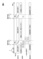
データ収容部72は、表示制御部73によって参照される複数のデータを収容する記憶領域である。データ収容部72は、RAM内に確保された記憶領域であってもよく、ストレージ内の一部の記憶領域であってもよい。データ収容部72には、ルックアップテーブル81、ミラー位置データ82,83及びグラフィックデータ84,85が表示制御部73によって参照可能に準備にされている。
The
ルックアップテーブル81(図2 Look up Table参照)は、画角位置とコンテンツとを紐付ける情報である(図3参照)。ミラー位置データ82(図2 Mirror Position Data A参照)は、画角VAを通常位置VP1に設定する場合の凹面鏡の角度位置を規定する情報である。ミラー位置データ83(図2 Mirror Position Data B参照)は、画角VAを重畳位置VP2に設定する場合の凹面鏡の角度位置を規定する情報である。各ミラー位置データ82,83は、ドライバのアイポイントEPの位置に合うように、ドライバによる調整が可能な値であってよい。グラフィックデータ84(図2 Graphic Data A参照)は、画角VAが通常位置VP1にある場合に使用される画像データ(素材データ)である。グラフィックデータ85(図2 Graphic Data B参照)は、画角VAが重畳位置VP2にある場合に使用される画像データ(素材データ)である。
The lookup table 81 (see Look up Table in FIG. 2) is information that associates the viewing angle position with the content (see FIG. 3). The mirror position data 82 (see Mirror Position Data A in FIG. 2) is information that defines the angular position of the concave mirror when the viewing angle VA is set to the normal position VP1. The mirror position data 83 (see Mirror Position Data B in FIG. 2) is information that defines the angular position of the concave mirror when setting the viewing angle VA to the superimposition position VP2. Each of the
表示制御部73は、PGU61及びアクチュエータ63を統合制御する制御部であり、PGU61へ向けて出力する映像データ及び制御信号と、アクチュエータ63へ向けて出力する駆動信号とを生成する。表示制御部73は、情報取得部71にて把握されるARスイッチ68のオン及びオフ状態に基づき、重畳位置VP2に画角VAを移動させる作動の有効及び無効を切り替える。表示制御部73は、ARスイッチ68がオフ状態である場合、画角VAを通常位置VP1に固定し、重畳コンテンツCTsの表示を中断する。
The
表示制御部73は、情報取得部71にて取得される情報と、ルックアップテーブル81の内容とに基づき、画角VAの位置を決定すると共に、決定した画角位置に基づき、虚像表示させるコンテンツを選択する。表示制御部73は、コンテンツの選択結果に基づき、映像データの生成に使用する画像の素材データを、各グラフィックデータ84,85からを抽出する。表示制御部73は、各グラフィックデータ84,85から生成した画像データと、メータECU32より提供される画像データとを適宜組み合わせ、映像データの各フレーム画像を生成する。表示制御部73は、連続した多数のフレーム画像よりなる映像データを、PGU61に逐次出力する。
The
表示制御部73は、画角VAの位置を移動させる場合、アクチュエータ63によって凹面鏡を機械的な回動させる作動に時間(例えば1秒程度)を必要とする。そのため、通常位置VP1及び重畳位置VP2の一方から他方への画角VAの移動を完了させた後に、移動後の画角VA内に虚像Vi(特定コンテンツCTis)を表示させる場合、画角VAの移動に起因した表示開始までのタイムラグが生じる。こうしたタイムラグがドライバの違和感を惹起しないように、表示制御部73は、特定コンテンツCTisに予め関連付けられた関連コンテンツCTrの表示を、画角VAの移動完了前に開始させる。
When the
具体的に、表示制御部73は、図4及び図2に示すように、通常位置VP1から重畳位置VP2に画角VAを移動させる場合に、関連コンテンツCTrを表示させる。関連コンテンツCTrは、通常位置VP1から重畳位置VP2へとアクチュエータ63が画角VAを移動させた後に、重畳位置VP2の画角VA内に表示される特定コンテンツCTisと関連した様態で表示される。関連しているとは、例えば関連コンテンツCTrが特定コンテンツCTisに誘目すること、関連コンテンツCTrが特定コンテンツCTisと同化していくこと、特定コンテンツCTisの一部が関連コンテンツCTrとして表示されること等を意味する。また、別の一例として、ドライバに同一と認識される程度に類似又は同一の表示色とされることで、特定コンテンツCTis及び関連コンテンツCTrが表示上で関連付けられていてもよい。さらに、関連コンテンツCTrが特定コンテンツCTisと同一の情報を含む場合も、関連コンテンツCTrは、特定コンテンツCTisに関連する様態となる。
Specifically, as shown in FIGS. 4 and 2, the
関連コンテンツCTrには、第一関連コンテンツCTr1及び第二関連コンテンツCTr2が含まれている。第一関連コンテンツCTr1は、通常位置VP1からの画角VAの移動をアクチュエータ63が開始させる時刻t1よりも前に、表示を開始される。第一関連コンテンツCTr1は、時刻t1にて表示を終了される。第一関連コンテンツCTr1は、例えば通常位置VP1にて表示される非重畳コンテンツCTnの背景として表示され、時刻t1にて表示を終了されるまでに複数回点滅する。 The related content CTr includes a first related content CTr1 and a second related content CTr2. The display of the first related content CTr1 is started before the time t1 at which the actuator 63 starts moving the angle of view VA from the normal position VP1. The display of the first related content CTr1 is ended at time t1. The first related content CTr1 is displayed, for example, as a background of the non-superimposed content CTn displayed at the normal position VP1, and blinks multiple times until the display is ended at time t1.
第二関連コンテンツCTr2は、アクチュエータ63によって画角VAが移動する移動中の期間(以下、移動期間TM1)において表示される。第二関連コンテンツCTr2は、第一関連コンテンツCTr1の表示が終了される時刻t1以後に表示を開始され、画角VAの移動が完了する時刻t2以前に表示を終了される。第二関連コンテンツCTr2は、第一関連コンテンツCTr1とは異なる様態のコンテンツである。例えば、第一関連コンテンツCTr1が非重畳コンテンツCTnとされる一方で、第二関連コンテンツCTr2は、重畳コンテンツCTs又は非重畳コンテンツCTnのいずれか一方とされる。表示制御部73は、画角位置が重畳位置VP2に近づくほど、第二関連コンテンツCTr2の輝度を連続的又は段階的に高くするトーンアップの表示変化を生じさせる。これにより、第二関連コンテンツCTr2は、画角VAの移動が経過するに従い、誘目性の高い表示物となる。
The second related content CTr2 is displayed during a moving period (hereinafter referred to as moving period TM1) in which the viewing angle VA is moved by the
一方、重畳位置VP2から通常位置VP1に画角VAを移動させる場合、表示制御部73は、関連コンテンツCTrの表示を実施しない。表示制御部73は、重畳位置VP2から通常位置VP1への画角VAの移動をアクチュエータ63が開始する時刻t3よりも前に、特定コンテンツCTisの重畳表示を終了させる。表示制御部73は、アクチュエータ63によって画角VAが移動する移動中の期間(以下、移動期間TM2)において、全ての虚像表示を一時的に中断する。表示制御部73は、画角位置が通常位置VP1に到達する時刻t4、又は時刻t4から所定時間(例えば1秒程度)経過したタイミングで、非重畳コンテンツCTnの表示を再開させる。尚、一部の特定コンテンツCTisを表示させる場合、移動期間TM1にて表示する関連コンテンツCTrが、移動期間TM2においても表示されてよい。
On the other hand, when moving the viewing angle VA from the superimposed position VP2 to the normal position VP1, the
メータECU32は、HUD100でのアクチュエータ63による画角VAの位置の切り替えに連携させて、メータディスプレイ31の表示画面の表示を変更する。メータECU32は、特定コンテンツCTisに関連する詳細情報PDiを表示画面に表示させている。詳細情報PDiは、特定コンテンツCTisと同種の情報であって、特定コンテンツCTisよりも詳細な内容を、ドライバに提示する。
The
通常位置VP1から重畳位置VP2への画角VAの移動がある場合、メータECU32は、時刻t1から時刻t2までの移動期間TM1において、画面表示された詳細情報PDiの画像輝度を連続的又は段階的に低くするトーンダウンの表示変化を生じさせる。これにより、画角VAの移動が経過するに従い、詳細情報PDiは、誘目性の低い表示物となる。その結果、メータ表示装置30の画面表示からHUD100による虚像表示に輝度が引き渡されるような表示変化となり、ドライバの視線が前景に誘導される。
When the angle of view VA moves from the normal position VP1 to the superimposed position VP2, the
メータECU32は、重畳位置VP2への画角VAの移動が完了する時刻t2において、詳細情報PDiを非表示とする。メータECU32は、画角VAが重畳位置VP2にあり、特定コンテンツCTisの表示が継続される期間において、詳細情報PDiの非表示の状態を継続する。これにより、詳細情報PDiがドライバを誘目して、外界の視認を阻害する事態は、生じなくなる。尚、詳細情報PDiを除く他の画像の画面表示は、時刻t2から時刻t3の期間においても継続される。
The
一方、重畳位置VP2から通常位置VP1への画角VAの移動がある場合、メータECU32は、特定コンテンツCTisの表示が終了されるタイミングで、詳細情報PDiの画面表示を再開させる。一例として、画角VAの移動が開始される時刻t3にて、詳細情報PDiの表示は再開される。以上により、特定コンテンツCTisが非表示になった後も、特定コンテンツCTisによって提供されていた情報を確認できる状態が維持される。
On the other hand, when the angle of view VA moves from the superimposed position VP2 to the normal position VP1, the
次に、通常位置VP1から重畳位置VP2へ画角VAを移動させて、特定コンテンツCTisを表示させる複数のシーンを、図5~図31に基づき、図1~図4を参照しつつ、以下説明する。 Next, a plurality of scenes in which the viewing angle VA is moved from the normal position VP1 to the superimposed position VP2 and the specific content CTis is displayed will be described below based on FIGS. 5 to 31 and with reference to FIGS. 1 to 4. do.
<車線逸脱警告>
図5~図10には、表示システム110によって実施される車線逸脱警告が複数パターン例示されている。図5~図7にはパターン1の車線逸脱警告が示されており、図5,図6及び図7にはパターン2の車線逸脱警告が示されており、図5,図9及び図10にはパターン3の車線逸脱警告が示されている。
<Lane departure warning>
5 to 10 illustrate a plurality of patterns of lane departure warnings executed by the
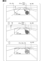
表示制御部73は、パターン1~3の車線逸脱警告が開始される以前に、通常位置VP1にある画角VAにスピードメータCTvを表示させている(図5上段参照)。スピードメータCTvは、車速をデジタル表示する非重畳コンテンツCTnである。表示制御部73は、情報取得部71による車線逸脱情報の取得をトリガとして、車線逸脱警告の実施を決定する。表示制御部73は、スピードメータCTvの表示を継続しつつ、点滅背景CTBを表示させる(図5下段参照)。
The
点滅背景CTBは、第一関連コンテンツCTr1として表示される非重畳コンテンツCTnである。点滅背景CTBは、画角VAの全体を塗り潰すような横長の矩形状の画像である。点滅背景CTBは、スピードメータCTvの視認を妨げないよう、スピードメータCTvの背景となるように表示される。点滅背景CTBは、例えば赤色等の警告色の虚像Viとされる。点滅背景CTBは、複数回の点滅後、時刻t1にてスピードメータCTvと共に表示を終了される。 The blinking background CTB is non-superimposed content CTn displayed as the first related content CTr1. The blinking background CTB is a horizontally long rectangular image that fills the entire viewing angle VA. The blinking background CTB is displayed as a background of the speedometer CTv so as not to obstruct the visibility of the speedometer CTv. The blinking background CTB is, for example, a virtual image Vi of a warning color such as red. After blinking a plurality of times, the blinking background CTB is finished displaying together with the speedometer CTv at time t1.
パターン1の車線逸脱警告では、時刻t1にて画角VAの移動が開始されると、表示制御部73は、誘導コンテンツCTGnの表示を開始させる(図6上段参照)。誘導コンテンツCTGnは、第二関連コンテンツCTr2として表示される非重畳コンテンツCTnである。誘導コンテンツCTGnは、点滅背景CTBとは異なる様態の関連コンテンツCTrであり、画角VAの一部を塗り潰すように表示される非点滅の画像である。誘導コンテンツCTGnは、画角VAの下縁に接する横長矩形状を呈し、点滅背景CTBと同様に赤色等の警告色の虚像Viとされる。誘導コンテンツCTGnの上下方向の幅は、表示開始の時点で垂直画角の半分から3分の1程度とされる。表示制御部73は、画角VAの上方への移動に合わせて誘導コンテンツCTGnを上下方向に縮小しつつ、ドライバの見た上において誘導コンテンツCTGnの全体を上方へ移動させる(図6下段参照)。表示制御部73は、画角VAが重畳位置VP2に到達する時刻t2以前に誘導コンテンツCTGnの表示を終了させる。
In the lane departure warning of
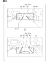
表示制御部73は、時刻t2にて重畳位置VP2への画角VAの移動を完了すると、逸脱警告コンテンツCTdwの表示を開始させる(図7上段参照)。逸脱警告コンテンツCTdwは、車線逸脱警告における特定コンテンツCTisである。逸脱警告コンテンツCTdwは、前景中の自車車線の路面を重畳の対象物とする重畳コンテンツCTsであり、走行中の自車車線からの車両Aの逸脱を警告する。逸脱警告コンテンツCTdwは、路面重畳画像Prs及び境界強調画像Pelを含んでいる。
When the
路面重畳画像Prsは、赤色等の警告色で虚像表示され、自車車線の前方路面の一部を塗り潰すように重畳表示される。車両Aが左側の区画線Lmlから逸脱しそうな場合、路面重畳画像Prsは、自車左側の区画線Lmlの近傍に重畳される。路面重畳画像Prsは、自車左側の区画線Lmlから自車右側の区画線Lmrへ向けて、繰り返し移動するアニメーションとして表示され(図7下段参照)、自車車線の中央への移動をドライバに促す。 The road surface superimposed image Prs is displayed as a virtual image in a warning color such as red, and is superimposed so as to fill out a part of the road surface in front of the vehicle lane. When vehicle A is likely to deviate from the left lane marking Lml, the road surface superimposed image Prs is superimposed near the lane marking Lml on the left side of the host vehicle. The road surface superimposed image Prs is displayed as an animation that repeatedly moves from the marking line Lml on the left side of the vehicle to the marking line Lmr on the right side of the vehicle (see the lower part of FIG. 7), and prompts the driver to move to the center of the vehicle lane. prompt.
境界強調画像Pelは、路面重畳画像Prsとは異なる表示色(例えば白色)の画像である。車両Aが自車車線の左側に逸脱しそうな場合、境界強調画像Pelは、自車左側の区画線Lmlに沿って細帯状に延伸する形状で、路面重畳画像Prsと区画線Lmlとの間に配置される。境界強調画像Pelは、路面重畳画像Prsのアニメーションに合わせて表示及び非表示の各状態を繰り返し、路面重畳画像Prsが区画線Lmlから離れるタイミングで非表示となる(図7下段参照)。尚、車両Aが自車車線の右側に逸脱しそうな場合、路面重畳画像Prs及び境界強調画像Pelは、自車右側に区画線Lmrに沿って表示される。 The boundary emphasized image Pel is an image of a display color (for example, white) different from that of the road surface superimposed image Prs. When vehicle A is likely to deviate to the left side of its own lane, the boundary enhanced image Pel has a shape that extends in a narrow strip along the lane marking Lml on the left side of the vehicle, and there is a border between the road surface superimposed image Prs and the marking line Lml. Placed. The boundary emphasized image Pel repeats display and non-display states in accordance with the animation of the road surface superimposed image Prs, and becomes non-displayed at the timing when the road surface superimposed image Prs leaves the marking line Lml (see the lower part of FIG. 7). Note that when the vehicle A is likely to deviate to the right side of the own vehicle lane, the road surface superimposed image Prs and the boundary emphasized image Pel are displayed on the right side of the own vehicle along the marking line Lmr.
パターン2の車線逸脱警告では、時刻t1にて画角VAの移動が開始されると、表示制御部73は、路面重畳画像Prs及び誘導コンテンツCTGsの表示を開始させる(図8上段参照)。路面重畳画像Prs及び誘導コンテンツCTGsは、第二関連コンテンツCTr2として表示される重畳コンテンツCTsである。
In pattern 2 lane departure warning, when the angle of view VA starts to move at time t1, the
路面重畳画像Prsは、逸脱警告コンテンツCTdw(図9参照)の一部であり、自車車線の前方路面の一部を塗り潰すように、逸脱側の区画線Lmlに臨む位置に重畳表示される。路面重畳画像Prsは、前方路面と共に自車に接近する重畳コンテンツCTsであってもよく、自車から所定距離の前方路面に重畳される重畳コンテンツCTsであってもよい。 The road surface superimposed image Prs is a part of the departure warning content CTdw (see FIG. 9), and is superimposed and displayed at a position facing the departure side marking line Lml so as to fill out a part of the road surface in front of the own vehicle lane. . The road surface superimposed image Prs may be superimposed content CTs that approaches the vehicle along with the road ahead, or may be superimposed content CTs that is superimposed on the road surface at a predetermined distance from the vehicle.
誘導コンテンツCTGsは、点滅背景CTB(図5参照)とは異なる様態の関連コンテンツCTrであり、画角VAの一部を塗り潰すように表示される。誘導コンテンツCTGsは、パターン1の誘導コンテンツCTGn(図6参照)と同様に、画角VAの下縁に接した横長矩形状を呈する赤色等の虚像Viである。誘導コンテンツCTGsは、ドライバから見て路面重畳画像Prsの手前側に配置される。表示制御部73は、画角VAの上方への移動中に前景中の消失点へ向けて誘導コンテンツCTGsを移動させる。具体的に、誘導コンテンツCTGsは、画角VAの上方への移動に合わせて、アスペクト比を維持したまま上下方向及び左右方向に縮小されつつ、区画線Lml,Lmrの間に収まるように上方へ移動する(図8下段参照)。こうした様態変化により、誘導コンテンツCTGsは、自車車線を奥側に移動するように視認され、ドライバの視線を遠方に誘導する。
The guiding content CTGs is related content CTr that is different from the blinking background CTB (see FIG. 5), and is displayed so as to fill out a part of the viewing angle VA. Like the guiding content CTGn of pattern 1 (see FIG. 6), the guiding content CTGs is a virtual image Vi of red or the like having a horizontally long rectangular shape touching the lower edge of the viewing angle VA. The guidance content CTGs is arranged on the near side of the road surface superimposed image Prs when viewed from the driver. The
表示制御部73は、時刻t2にて重畳位置VP2への画角VAの移動を完了すると、逸脱警告コンテンツCTdwの表示を開始させる(図9上段参照)。パターン2の逸脱警告コンテンツCTdwは、路面重畳画像Prs及び境界強調画像Pelを含む重畳コンテンツCTsである。路面重畳画像Prsは、上述したように画角VAの移動中に表示を開始され、画角VAの移動が完了した後も表示を継続される。路面重畳画像Prsは、自車から所定の距離にある前方路面に重畳される。
When the
境界強調画像Pelは、例えば白色等で描画され、路面重畳画像Prsに重ねて表示される。境界強調画像Pelは、自車車線の中央への移動をドライバに促すように、中央側を指し示す三角形状に描画される。表示制御部73は、逸脱側の区画線Lmlに沿って複数の境界強調画像Pelを所定の間隔で表示させる。複数の境界強調画像Pelは、自車の走行に合わせて、拡大されつつ区画線Lmlに沿って路面重畳画像Prs上を移動し、前方路面と共に自車に接近するようにドライバに視認される(図9下段参照)。
The boundary emphasized image Pel is drawn, for example, in white, and is displayed superimposed on the road surface superimposed image Prs. The boundary enhanced image Pel is drawn in a triangular shape pointing toward the center so as to urge the driver to move toward the center of the vehicle lane. The
パターン3の車線逸脱警告では、パターン2の誘導コンテンツCTGs(図8参照)の表示が省略される。表示制御部73は、路面重畳画像Prsを第二関連コンテンツCTr2として表示させる(図10上段参照)。路面重畳画像Prsは、逸脱側の区画線Lmlに臨む配置で重畳表示され、上方への画角VAの移動に合わせて、自車車線からはみ出さない範囲で、前景中の消失点へ向けて拡大される(図10上段参照)。路面重畳画像Prsは、画角VAの移動が完了した後も、逸脱警告コンテンツCTdwの一部として、重畳位置VP2の画角VA内に継続表示される(図9参照)。
In the lane departure warning of
<ACCステータスの変更通知>
図11~図19には、表示システム110によって実施されるACCステータスの変更通知が複数パターン例示されている。図11~図13にはパターン1のACCステータスの変更通知が示されており、図11,図14及び図15にはパターン2のACCステータスの変更通知が示されている。さらに、図11,図16及び図17にはパターン3のACCステータスの変更通知が示されており、図11,図18及び図19にはパターン4のACCステータスの変更通知が示されている。
<ACC status change notification>
11 to 19 illustrate a plurality of patterns of ACC status change notifications performed by the
運転支援ECU23にてACC機能が作動している場合、通常位置VP1にある画角VAには、スピードメータCTvに加えて、目標車速CTts及び目標車間CTtdが表示される(図11上段参照)。目標車速CTts及び目標車間CTtdは、ACC機能に設定された制御目標値を示す非重畳コンテンツCTnである。目標車速CTtsは、ACC機能が車両Aを定速巡航させる場合に上限となる車速を示す。目標車間CTtdは、ACC機能が車両Aを前走車Afに追従走行させる場合の車間距離の長さ(以下、目標車間距離)を示す。
When the ACC function is activated in the
ACCステータスの変更通知は、ACC機能に設定された目標車間距離がドライバによって変更(長く)された場合に実施される(図11下段参照)。ACCステータスの変更通知が開始される以前の表示は、パターン1~4で共通している。表示制御部73は、目標車間距離の変更を示すステータス情報の取得をトリガとして、ACCステータスの変更通知の実施を決定し、画角VAの移動を開始させる時刻t1以前に、スピードメータCTv及び目標車速CTtsを非表示とする。
The ACC status change notification is performed when the target inter-vehicle distance set in the ACC function is changed (lengthened) by the driver (see the lower part of FIG. 11). The display before the ACC status change notification starts is common to
パターン1のACCステータスの変更通知では、時刻t1にて画角VAの移動が開始されると、表示制御部73は、目標車間CTtdの表示輝度を徐々に低下させる。こうしたトーンダウンの表示変化により、目標車間CTtdは、移動期間TM1にて非表示となる。加えて表示制御部73は、部分表示コンテンツCTusの表示を開始させる(図12参照)。
In the
部分表示コンテンツCTusは、関連コンテンツCTrとして表示される。部分表示コンテンツCTusは、画角VAの移動完了後に表示される特定コンテンツCTis(図13参照)の一部である。画角VAが上方に移動する場合、特定コンテンツCTisの下側部分が、部分表示コンテンツCTusとして表示される。部分表示コンテンツCTusは、ブロック画像Pdb及び一組の区画線画像Pblを含む重畳コンテンツCTsであり、前方路面に重畳表示される。 Partial display content CTus is displayed as related content CTr. The partial display content CTus is a part of the specific content CTis (see FIG. 13) that is displayed after the movement of the viewing angle VA is completed. When the viewing angle VA moves upward, the lower part of the specific content CTis is displayed as the partial display content CTus. The partial display content CTus is superimposed content CTs including a block image Pdb and a set of marking line images Pbl, and is superimposed and displayed on the road surface ahead.
表示制御部73は、時刻t2にて重畳位置VP2への画角VAの移動を完了すると、車間通知コンテンツCTfdの表示を開始させる(図13上段参照)。車間通知コンテンツCTfdは、ACCステータスの変更通知における特定コンテンツCTisである。車間通知コンテンツCTfdは、前景中の自車車線の路面を重畳の対象物とする重畳コンテンツCTsであり、ACC機能による車間維持制御の動作状態の変化、具体的には、前走車Afまでの車間距離を拡大するための減速制御の実施をドライバに通知する。車間通知コンテンツCTfdは、ブロック画像Pdb及び一組の区画線画像Pblを含んでいる。
When the
ブロック画像Pdbは、青色又は緑色等で虚像表示され、自車車線の前方路面の中央に重畳される台形状の画像である。ブロック画像Pdbは、ドライバの見た目上において前走車Afと重ならないように、前走車Afの下方に表示される。ACC機能による減速制御により前走車Afまでの車間距離が拡大すると、表示制御部73は、前走車Afの下方に表示するブロック画像Pdbの数を増加させる(図13上段参照)。
The block image Pdb is a trapezoidal image that is displayed as a virtual image in blue, green, or the like, and is superimposed on the center of the road surface in front of the own vehicle lane. The block image Pdb is displayed below the vehicle in front Af so as not to overlap the vehicle in front Af in the driver's view. When the inter-vehicle distance to the vehicle in front Af increases due to deceleration control by the ACC function, the
区画線画像Pblは、ブロック画像Pdbと実質同一の青色又は緑色等で虚像表示され、ブロック画像Pdbの両側に一つずつ重畳される。各区画線画像Pblは、隣接する区画線Lml,Lmrに沿って自車側から消失点へ向けて延伸する細帯状の画像である。区画線画像Pblは、ドライバの見た目上での前走車Afとの重なりを許容されており、重畳位置VP2にある画角VAの下縁から上縁まで斜め方向に延伸している。 The partition line image Pbl is displayed as a virtual image in substantially the same blue or green color as the block image Pdb, and is superimposed one on each side of the block image Pdb. Each marking line image Pbl is a narrow strip-shaped image that extends from the own vehicle side toward the vanishing point along the adjacent marking lines Lml and Lmr. The marking line image Pbl is allowed to overlap with the vehicle in front Af in the driver's view, and extends diagonally from the lower edge to the upper edge of the angle of view VA at the superimposed position VP2.
表示制御部73は、ACC機能による目標車間距離の変更が完了すると、ACCステータスの変更通知を終了し、画角VAを通常位置VP1に復帰させる。車間通知コンテンツCTfdは、画角VAの移動が開始される時刻t3以前に非表示とされてもよく、画角VAの移動に合わせて上側から下側へ向けて徐々に非表示とされてもよい。表示制御部73は、時刻t4にて通常位置VP1への画角VAの移動を完了すると、スピードメータCTv、目標車速CTts及び目標車間CTtdの表示を再開させる(図11上段参照)。
When the change of the target inter-vehicle distance by the ACC function is completed, the
パターン2のACCステータスの変更通知でも、時刻t1にて画角VAの移動が開始されると、表示制御部73は、目標車間CTtdをトーンダウンによって非表示としつつ、部分表示コンテンツCTusの表示を開始させる(図14参照)。部分表示コンテンツCTusは、画角VAの移動完了後に表示される特定コンテンツCTis(図15参照)の一部であり、バー画像Pbr及び一組の区画壁画像Pbbを含んでいる。表示制御部73は、部分表示コンテンツCTusと共に、スピードメータCTvをさらに表示させる。バー画像Pbr、区画壁画像Pbb及びスピードメータCTvは、画角VAの移動に合わせて、下側から上側へ徐々に表示されていく。
Even in the pattern 2 ACC status change notification, when the angle of view VA starts to move at time t1, the
表示制御部73は、時刻t2にて重畳位置VP2への画角VAの移動を完了すると、車間通知コンテンツCTfdの表示を開始させる(図15上段参照)。車間通知コンテンツCTfdは、上述したバー画像Pbr及び一組の区画壁画像Pbbを含んでいる。バー画像Pbrは、パターン1のブロック画像Pdb(図13参照)に相当する画像であり、水平方向に棒状に延伸する形状である。バー画像Pbrは、ドライバの見た目上において前走車Af及びスピードメータCTvの間に表示される。ACC機能の減速制御によって前走車Afまでの車間距離が拡大されると、前走車Afの下方に表示されるバー画像Pbrの数は、増加する(図15下段参照)。
When the
区画壁画像Pbbは、パターン1の区画線画像Pbl(図13参照)に相当する画像であり、バー画像Pbr及びスピードメータCTvの両側に重畳される。各区画壁画像Pbbは、路面から上方に立設された壁形状の画像部を複数含み、隣接する区画線Lml,Lmrに沿って壁状に並んでいる。各区画壁画像Pbbは、ACC機能による減速制御によって前走車Afまでの車間距離が拡大すると、壁形状の画像部の数を増加させる(図15下段参照)。 The partition wall image Pbb is an image corresponding to the partition line image Pbl of pattern 1 (see FIG. 13), and is superimposed on both sides of the bar image Pbr and the speedometer CTv. Each partition wall image Pbb includes a plurality of wall-shaped image parts erected upward from the road surface, and is arranged in a wall shape along adjacent partition lines Lml and Lmr. In each partition wall image Pbb, when the inter-vehicle distance to the preceding vehicle Af increases due to deceleration control by the ACC function, the number of wall-shaped image parts increases (see the lower part of FIG. 15).
パターン3のACCステータスの変更通知でも、時刻t1にて画角VAの移動が開始されると、表示制御部73は、目標車間CTtdをトーンダウンさせつつ、部分表示コンテンツCTusの表示を開始させる(図16参照)。部分表示コンテンツCTusは、画角VAの移動完了後に表示される特定コンテンツCTis(図17参照)の一部であり、当該特定コンテンツCTisの関連コンテンツCTrである。部分表示コンテンツCTusは、前方路面に重畳表示されるブロック画像Pdb及び一組の区画線画像Pblを含んでいる。ブロック画像Pdb及び区画線画像Pblは、画角VAの上方への移動に合わせて、下側から上側へ徐々に表示されていく。
Even in the ACC status change notification of
表示制御部73は、時刻t2にて重畳位置VP2への画角VAの移動を完了すると、ブロック画像Pdb及び各区画線画像Pblの全体を描画することで、特定コンテンツCTisとしての車間通知コンテンツCTfdの表示を開始させる(図17上段参照)。ブロック画像Pdbは、台形枠状に描画され、前走車Afを下方から強調する強調部を含んでいる。ACC機能の減速制御によって前走車Afまでの車間距離が拡大すると、複数のブロック画像Pdbが強調部の下方に連続的に描画される(図17下段参照)。区画線画像Pblは、パターン1の区画線画像Pbl(図13参照)と実質同一の細帯状の画像である。各区画線画像Pblは、ブロック画像Pdbの左右両側に、区画線Lml,Lmrに沿った姿勢で配置される。
When the
パターン4のACCステータスの変更通知でも、時刻t1にて画角VAの移動が開始されると、表示制御部73は、目標車間CTtdをトーンダウンさせつつ、部分表示コンテンツCTus及びスピードメータCTvの表示を開始させる(図18参照)。部分表示コンテンツCTusは、特定コンテンツCTis(図19参照)の一部であり、当該特定コンテンツCTisの関連コンテンツCTrである。部分表示コンテンツCTusは、ブロック画像Pdb及び区画線画像Pblを含む重畳コンテンツCTsである。ブロック画像Pdb、各区画線画像Pbl及びスピードメータCTvは、画角VAの上方への移動に合わせて、下側から上側へ徐々に表示されていく。
Even in the
表示制御部73は、時刻t2にて重畳位置VP2への画角VAの移動を完了すると、特定コンテンツCTisとしての車間通知コンテンツCTfdの表示を開始させる。(図19上段参照)。車間通知コンテンツCTfdは、スピードメータCTvの奥側に表示される。車間通知コンテンツCTfdには、画角VAの移動中に表示を開始されたブロック画像Pdb及び区画線画像Pblに加えて、バー画像Pbrが含まれている。ブロック画像Pdb及び区画線画像Pblは、パターン1(図13参照)と実質同一の画像である。バー画像Pbrは、前走車Afの下方の路面に重畳され、前走車Afを下側から強調する。表示制御部73は、ACC機能の減速制御によって前走車Afまでの車間距離が拡大すると、バー画像Pbrを上方へ移動させつつ、バー画像Pbrの下側に複数のブロック画像Pdbを追加表示する(図19下段参照)。
When the
<ターンバイターン表示>
図20~図25には、表示システム110によって実施される経路案内が複数パターン例示されている。図20~図22にはパターン1の経路案内におけるターンバイターン表示が示されており、図20,図21及び図23にはパターン2のターンバイターン表示が示されている。さらに、図20,図21及び図24にはパターン3のターンバイターン表示が示されており、図20,図21及び図25にはパターン4のターンバイターン表示が示されている。
<Turn-by-turn display>
20 to 25 illustrate multiple patterns of route guidance performed by the
ナビゲーションECU22による目的地への経路案内が実施されている場合、案内ポイントの接近に伴い、通常位置VP1にある画角VAには、スピードメータCTvに加えて、ルートアイコンCTirが表示される(図20下段参照)。案内ポイントは、例えば交差点、合流区間及び分岐区間等の案内エリア内に特定のノードを基準に設定される。
When route guidance to a destination is being performed by the
ルートアイコンCTirは、案内ポイントまでの残距離と、案内ポイントでの右左折等の方向を示す非重畳コンテンツCTnである。表示制御部73は、直近の案内エリアについての経路情報が情報取得部71にて取得されたことをトリガとして、ターンバイターン表示の実施を決定する。表示制御部73は、ルートアイコンCTirを表示させた後、スピードメータCTv及びルートアイコンCTirを含む全てのコンテンツを非表示とし、重畳位置VP2への画角VAの移動を開始する。
The route icon CTir is non-superimposed content CTn that indicates the remaining distance to the guide point and directions such as right and left turns at the guide point. The
表示制御部73は、時刻t1にて画角VAの移動を開始させると、画角VAが移動する移動期間TM1にて、レーン強調コンテンツCTelの表示を開始させる(図21参照)。レーン強調コンテンツCTelは、関連コンテンツCTrとして表示される重畳コンテンツCTsあり、前景中の自車車線の路面に重畳されて、走行中の自車車線を強調する。レーン強調コンテンツCTelは、左右の区画線Lml,Lmrの内側に配置される細帯状の画像である(図21上段参照)。レーン強調コンテンツCTelは、画角VAの上方への移動に合わせて、各区画線Lml,Lmrに沿って伸びていく(図21下段参照)。以上のように、ターンバイターン表示を行う場合に、関連コンテンツCTrとしてレーン強調コンテンツCTelを表示する処理は、パターン1~4において共通している。
When the
パターン1のターンバイターン表示では、時刻t2にて重畳位置VP2への画角VAの移動を完了すると、特定コンテンツCTisとしての経路案内コンテンツCTrgの表示が開始される(図22上段参照)。経路案内コンテンツCTrgには、接近通知画像Pap及び地点通知画像Ptpが含まれている。
In the turn-by-turn display of
接近通知画像Papは、時刻t2にて画角VAの下縁近傍に表示される。接近通知画像Papは、案内ポイントにおける自車の転回方向を指し示す複数の三角形状の画像部を有している。表示制御部73は、自車が案内ポイントへ接近するに従い、接近通知画像Papを拡大させつつ、画角VAの中央へ徐々に移動させる(図22下段参照)。
The approach notification image Pap is displayed near the lower edge of the viewing angle VA at time t2. The approach notification image Pap has a plurality of triangular image parts indicating the turning direction of the own vehicle at the guide point. As the host vehicle approaches the guide point, the
地点通知画像Ptpは、路面から浮かんでいるような様態で案内ポイントに重畳表示される。地点通知画像Ptpは、接近通知画像Papと同様に、自車の転回方向を指し示す複数の三角形状の画像部を有している。地点通知画像Ptpは、接近通知画像Papよりも後に画角VA内に表示され、自車が案内ポイントへ接近するに従って画角VAの中央に移動する。地点通知画像Ptpは、自車が交差点に進入するタイミングで、上方に移動してきた接近通知画像Papと衝突する。地点通知画像Ptp及び接近通知画像Papは、見た目上での衝突後に一体化されて、自車の転回方向をドライバに明示する非重畳コンテンツCTnとなる。 The point notification image Ptp is displayed superimposed on the guide point in such a manner that it appears to be floating above the road surface. Like the approach notification image Pap, the point notification image Ptp has a plurality of triangular image portions that indicate the turning direction of the own vehicle. The point notification image Ptp is displayed within the angle of view VA after the approach notification image Pap, and moves to the center of the angle of view VA as the host vehicle approaches the guide point. The point notification image Ptp collides with the approach notification image Pap that has moved upward at the timing when the own vehicle enters the intersection. The point notification image Ptp and the approach notification image Pap are integrated after the apparent collision, and become non-superimposed content CTn that clearly shows the turning direction of the own vehicle to the driver.
表示制御部73は、自車が案内ポイントである交差点から退出すると、経路案内コンテンツCTrgを非表示とした後、通常位置VP1への画角VAの移動を開始させる。表示制御部73は、通常位置VP1への画角VAの移動を完了させた所定時間後に、スピードメータCTvの表示を再開させる(図20上段参照)。
When the host vehicle exits the intersection that is the guidance point, the
パターン2のターンバイターン表示では、時刻t2にて重畳位置VP2への画角VAの移動が完了した後も、一対のレーン強調コンテンツCTelの表示が継続される(図23上段参照)。表示制御部73は、レーン強調コンテンツCTelによる自車車線の強調を所定時間継続させた後、経路案内コンテンツCTrgに含まれる表示物を、レーン強調コンテンツCTelから接近通知画像Papに切り替える(図23中段参照)。接近通知画像Papは、自車の転回方向を指し示す複数の三角形状の画像部を有している。複数の三角形状の画像部は、自車の進行方向に沿って、自車車線の路面中央に一列に並んで重畳表示される。各画像部は、案内ポイントに自車が接近するに従って、画角VAの下方に連続的に移動し、順にフレームアウトする。
In the turn-by-turn display of pattern 2, the display of the pair of lane emphasis contents CTel continues even after the movement of the viewing angle VA to the superimposition position VP2 at time t2 is completed (see the upper part of FIG. 23). After the
表示制御部73は、自車が交差点に進入するタイミングで、経路案内コンテンツCTrgに含まれる表示物を、接近通知画像Papから地点通知画像Ptpへと切り替える(図23下段参照)。地点通知画像Ptpは、転回方向を示す三角形状の画像部を複数組み合わせてなる非重畳コンテンツCTnである。地点通知画像Ptpは、右左折を開始した後も自車が交差点から退出するまで表示を継続される。
The
パターン3のターンバイターン表示では、時刻t2にて重畳位置VP2への画角VAの移動が完了した後、一対のレーン強調コンテンツCTelの表示が継続されると共に、バー画像Pbrが追加表示される(図24上段参照)。バー画像Pbrは、画角VAの水平方向に沿って棒状に延伸する画像であり、一対のレーン強調コンテンツCTelの間に配置される。
In the turn-by-turn display of
表示制御部73は、レーン強調コンテンツCTel及びバー画像Pbrによる自車車線の強調を所定時間継続した後、経路案内コンテンツCTrgに含まれる表示物を、接近通知画像Papに切り替える(図24中段参照)。接近通知画像Papは、案内ポイントまでの残距離を数値で示す画像部と、案内ポイントでの右左折の方向を示す矢印形状の画像部とを有している。接近通知画像Papは、案内ポイントに自車が接近するに従って路面と共に自車側に移動し、画角VAから順にフレームアウトする。
After continuing to emphasize the own vehicle lane using the lane emphasis content CTel and the bar image Pbr for a predetermined period of time, the
表示制御部73は、案内ポイントが画角VA内に入るタイミングで、経路案内コンテンツCTrgに含まれる表示物を、接近通知画像Papから地点通知画像Ptpへと切り替える(図24下段参照)。地点通知画像Ptpは、転回方向を示す三角形状の穴部が形成された横長矩形状の画像である。地点通知画像Ptpは、重畳位置VP2にある画角VAの略全体に表示される。地点通知画像Ptpは、右左折が開始された後も、自車が交差点から退出するまで表示を継続される。
The
パターン4のターンバイターン表示では、時刻t2にて重畳位置VP2への画角VAの移動が完了した後、接近通知画像Papを含む経路案内コンテンツCTrgの表示が開始される。接近通知画像Papは、画角VAの右隅に積み上げられた複数のブロック状の画像部(以下、固定画像部)と、路面に重畳されて自車に接近する複数のブロック状の画像部(以下、移動画像部)とを含んでいる(図25下段参照)。最下段の固定画像部は、自車に接近する移動画像部との衝突によって消失する(図25中段参照)。こうしたアニメーションの繰り返しにより、接近通知画像Papは、案内ポイントの接近をドライバに示す。
In the turn-by-turn display of
表示制御部73は、案内ポイントが画角VA内に入るタイミングで、経路案内コンテンツCTrgに含まれる表示物を、接近通知画像Papから地点通知画像Ptpへと切り替える(図25下段参照)。地点通知画像Ptpは、転回方向を示す三角形状の画像部を複数含む非重畳コンテンツCTnである。パターン4のターンバイターン表示でも、地点通知画像Ptpは、自車が交差点から退出するまで表示を継続される。
The
<標識認識支援表示>
図26~図31には、表示システム110によって実施される標識認識支援表示が複数パターン例示されている。標識認識支援表示では、関連コンテンツCTrは表示されない。図26~図28にはパターン1の標識認識支援表示が示されており、図26,図28及び図29にはパターン2の標識認識支援表示が示されている。さらに、図26,図28及び図30にはパターン3の標識認識支援表示が示されており、図26,図28及び図31にはパターン4の標識認識支援表示が示されている。
<Sign recognition support display>
26 to 31 illustrate a plurality of patterns of sign recognition support display performed by the
カメラECU21の標識認識機能が作動している場合、通常位置VP1にある画角VAには、スピードメータCTvに加えて、標識アイコンCTrsが表示される(図26参照)。標識アイコンCTrsは、過去に認識された道路標識RS(例えば制限速度60km/h)を模した非重畳コンテンツCTnである。カメラECU21が自車前方の道路標識RSを新たに検出すると、カメラECU21からHUD100に、検出した道路標識RSについての認識情報が出力される。表示制御部73は、情報取得部71による道路標識RSの認識情報の取得をトリガとして、標識認識支援表示の実施を決定する。パターン1~4の標識認識支援表示では、時刻t1,t3にて画角VAの移動が開始される以前に、スピードメータCTv及び標識アイコンCTrs、又は認識支援コンテンツCTra(図27参照)等のコンテンツは、非表示とされる。加えて、パターン1~4の標識認識支援表示では、画角VAの移動期間TM1,TM2において、全てのコンテンツの表示が一時的に中断される。
When the sign recognition function of the
パターン1の標識認識支援表示では、時刻t2にて重畳位置VP2に移動した画角VA内に、認識支援コンテンツCTraの表示が開始される(図27上段参照)。表示制御部73は、認識支援コンテンツCTraとして変更予告画像Ppnを最初に表示させる。変更予告画像Ppnは、道路標識RSを模した画像であり、新たに検出された道路標識RS(例えば制限速度40km/h)の内容を示す。変更予告画像Ppnは、標識アイコンCTrs(図26参照)よりも低彩度に描画され、標識アイコンCTrsよりも大きなサイズで虚像表示される。
In the sign recognition support display of
表示制御部73は、道路標識RSが接近すると、変更予告画像Ppnに加えて、地点通知画像Ptpをさらに表示させる(図27中段参照)。地点通知画像Ptpは、水平方向に延伸する棒状の画像であり、道路標識RSの設置位置を基準として、自車前方の路面に重畳表示される。地点通知画像Ptpは、自車前方の路面と共に変更予告画像Ppnに接近する。表示制御部73は、地点通知画像Ptpが変更予告画像Ppnと接触するタイミングで、輝度及び彩度を一時的に高めることにより、変更予告画像Ppnを強調表示させる(図27下段参照)。
When the road sign RS approaches, the
表示制御部73は、認識支援コンテンツCTraの表示を終了させた後、時刻t3にて画角VAの通常位置VP1への移動を開始する。表示制御部73は、通常位置VP1への画角VAの移動が完了する時刻t4の後に、スピードメータCTv及び標識アイコンCTrsの表示を再開させる(図28参照)。再表示された標識アイコンCTrsは、直前に非表示とされた変更予告画像Ppnと同一の内容(制限速度40km/h)となる。
After finishing displaying the recognition support content CTra, the
パターン2の標識認識支援表示では、重畳位置VP2に移動した画角VAの下縁から変更予告画像Ppnがフレームインするアニメーションにより、認識支援コンテンツCTraの表示が開始される(図29上段参照)。表示制御部73は、パターン1と同様に、地点通知画像Ptpをさらに表示させた後、地点通知画像Ptpを変更予告画像Ppnに衝突させる(図29中段参照)。表示制御部73は、地点通知画像Ptpと変更予告画像Ppnとを接触させた後、変更予告画像Ppnを強調状態のまま奥側に倒し、路面に貼り付いた姿勢に変化させる(図29下段参照)。
In the sign recognition support display of pattern 2, the display of the recognition support content CTra is started by an animation in which the change notice image Ppn is framed from the lower edge of the viewing angle VA that has been moved to the superimposed position VP2 (see the upper part of FIG. 29). Similar to
加えて表示制御部73は、地点通知画像Ptpに替えて、波紋画像Pwを表示させる。波紋画像Pwは、水平方向に延伸する棒状の画像であり、自車車線の路面に重畳表示される。波紋画像Pwは、自車車線に沿って進行方向へ高速で移動することで、新しい道路標識RSが有効となる区間を示唆する。表示制御部73は、画角VAから波紋画像Pwがフレームアウトするタイミングで認識支援コンテンツCTraの表示を終了させ、画角VAを通常位置VP1に戻す処理を開始する。
In addition, the
パターン3の標識認識支援表示では、重畳位置VP2に移動した画角VA内に、認識支援コンテンツCTraに加えて、スピードメータCTvが表示される。認識支援コンテンツCTraには、変更予告画像Ppn及び現在標識画像Pspが含まれている。変更予告画像Ppnは、現在標識画像Pspの奥側に表示される(図30上段参照)。変更予告画像Ppnは、自車前方の路面と共に自車側に移動し、現在標識画像Pspに接近する(図30中段参照)。
In the sign recognition support display of
現在標識画像Pspは、変更予告画像Ppnと同様に道路標識RSを模した画像である(図30上段参照)。現在標識画像Pspは、直前に非表示とされた標識アイコンCTrs(図28参照)と同一の内容(制限速度60km/h)を示す。現在標識画像Pspは、変更予告画像Ppnよりも手前側となる画角VA内の所定位置に表示される。
The current sign image Psp is an image imitating the road sign RS, similar to the change notice image Ppn (see the upper part of FIG. 30). The current sign image Psp shows the same content (
表示制御部73は、自車側に移動する変更予告画像Ppnを現在標識画像Pspに衝突させ、現在標識画像Pspの表示を終了させる(図30下段参照)。表示制御部73は、現在標識画像Pspに替えて、輝度及び彩度を高めた強調様態の変更予告画像Ppnを非重畳コンテンツCTnとして表示させる。その後、表示制御部73は、認識支援コンテンツCTraの表示を終了させ、画角VAの通常位置VP1への移動を開始させる。
The
パターン4の標識認識支援表示では、パターン2と実質同一の変更予告画像Ppn及び地点通知画像Ptpが認識支援コンテンツCTraとして表示される(図31上段及び中段参照)。パターン4では、波紋画像Pwの様態が、パターン2とは異なっている。具体的に、表示制御部73は、変更予告画像Ppnを奥側に傾斜させた後、変更予告画像Ppnから放射状に広がる円弧状の波紋画像Pwを表示させる(図31下段参照)。表示制御部73は、変更予告画像Ppnを起点として波紋画像Pwが広がるアニメーションを複数回繰り返し表示させた後、認識支援コンテンツCTraの表示を終了させる。
In the sign recognition support display of
ここまで説明した虚像表示方法を実現するための表示制御処理の詳細を、図32及び図33に基づき、図1及び図4を参照しつつ説明する。図32に示す表示制御処理は、画角VAの位置に紐付けてコンテンツを表示させる処理であり、起動後の初期処理を完了したヘッドアップECU70によって開始される。図33に示す表示制御処理は、HUD100による画角VAの移動に合わせて、表示画面の詳細情報PDiの状態を変更する処理であり、起動後の初期処理を完了したメータECU32によって開始される。
The details of the display control processing for realizing the virtual image display method described so far will be explained based on FIGS. 32 and 33, and with reference to FIGS. 1 and 4. The display control process shown in FIG. 32 is a process for displaying content in association with the position of the viewing angle VA, and is started by the head-up
図32に示す表示制御処理のS101では、ARスイッチ68のオンオフを示す信号を検出し、S102に進む。S102では、S101にて検出した信号に基づき、重畳位置VP2へ移動させた画角VA内に重畳コンテンツCTsを表示させるAR機能がオン状態にあるか否かを判定する。S102にて、AR機能がオフ状態にあると判定した場合、S112に進む。一方、S102にて、AR機能がオン状態にあると判定した場合、S103に進む。
In S101 of the display control process shown in FIG. 32, a signal indicating on/off of the
S103では、情報取得部71にて取得される種々の情報に基づき、ルックアップテーブル81を参照することで、画角VAの位置と、虚像表示するコンテンツとを決定し、S104に進む。S104では、S103での決定に基づき、画角VAの位置を切り替える切替作動の要否を判定する。S104にて、切替作動が不要であり、現在の画角位置を維持すると判定した場合、S111に進む。一方、S104にて、切替動作が必要と判定した場合、S105に進む。
In S103, the position of the viewing angle VA and the content to be displayed as a virtual image are determined by referring to the lookup table 81 based on various information acquired by the
S105では、切替作動の方向を判定する。重畳位置VP2から通常位置VP1へ画角VAを移動させる場合、S105からS106に進む。S106では、虚像Viの表示を全て終了させ、S107に進む。S107では、通常位置VP1に紐づくミラー位置データ82に基づき、拡大光学系62の凹面鏡を回動させて、画角VAを通常位置VP1に移動させる。
In S105, the direction of switching operation is determined. When moving the viewing angle VA from the superimposed position VP2 to the normal position VP1, the process proceeds from S105 to S106. In S106, the display of all virtual images Vi is ended, and the process proceeds to S107. In S107, the concave mirror of the magnifying
一方、通常位置VP1から重畳位置VP2へ画角VAを移動させる場合、S105からS108に進む。S108では、グラフィックデータ84を参照し、第一関連コンテンツCTr1の表示を開始させ、S109に進む。S109では、重畳位置VP2に紐づくミラー位置データ83に基づき、凹面鏡の回動による重畳位置VP2への画角VAの移動を開始させ、S110に進む。S110では、グラフィックデータ85を参照し、第二関連コンテンツCTr2の表示を開始させ、S111に進む。尚、特定コンテンツCTisに紐づく第一関連コンテンツCTr1がない場合、S108は省略されてよい。同様に、特定コンテンツCTisに紐づく第二関連コンテンツCTr2がない場合、S110は省略されてよい。
On the other hand, when moving the viewing angle VA from the normal position VP1 to the superimposed position VP2, the process advances from S105 to S108. In S108, the display of the first related content CTr1 is started with reference to the
S111では、画角位置を判定する。S111にて、通常位置VP1が維持されるか、又は通常位置VP1への移動が完了したと判定した場合、S112に進む。S112では、ミラー位置データ82に基づき、画角VAを通常位置VP1に設定し、S113に進む。S113では、グラフィックデータ84を参照し、S103にて決定された非重畳コンテンツCTnの表示を開始させる。尚、S107にて、通常位置VP1のミラー位置データ82が既に読み込まれている場合、S112は省略されてよい。
In S111, the viewing angle position is determined. If it is determined in S111 that the normal position VP1 is maintained or that the movement to the normal position VP1 is completed, the process advances to S112. In S112, the viewing angle VA is set to the normal position VP1 based on the
一方、S111にて、重畳位置VP2が維持されるか、又は重畳位置VP2への移動が完了したと判定した場合、S114に進む。S114では、ミラー位置データ83に基づき、画角VAを重畳位置VP2に設定し、S115に進む。S115では、グラフィックデータ85を参照し、S103にて決定された重畳コンテンツCTsの表示を開始させる。尚、S109にて、重畳位置VP2のミラー位置データ83が既に読み込まれている場合、S114は省略されてよい。
On the other hand, if it is determined in S111 that the superimposed position VP2 is maintained or that the movement to the superimposed position VP2 is completed, the process advances to S114. In S114, the viewing angle VA is set to the superimposition position VP2 based on the
図33に示す表示制御処理のS31では、ヘッドアップECU70との情報共有により、HUD100にて設定される画角VAの位置を把握し、S32に進む。S32では、S31にて把握した情報に基づき、画角位置の切替作動の有無を把握する。S32にて、画角位置が維持されると判定した場合、現在の詳細情報PDiの表示又は非表示の状態が維持される。尚、起動後の最初の処理では、詳細情報PDiの表示を開始する処理が適宜実施されてよい。
In S31 of the display control process shown in FIG. 33, the position of the viewing angle VA set in the
S32にて、切替作動があると判定した場合、S33に進む。S33では、画角VAの移動方向を判定する。S33にて、通常位置VP1へ画角VAが移動されると判定した場合、S34に進む。S34では、HUD100にて重畳コンテンツCTsの表示がオフにされるのを待機し、重畳コンテンツCTsが非表示となったタイミングでS35に進む。S35では、詳細情報PDiの表示を開始する。以上により、画角VAが通常位置VP1にある期間において、詳細情報PDiがドライバによって随時確認できるように表示画面に表示される。
If it is determined in S32 that there is a switching operation, the process advances to S33. In S33, the moving direction of the angle of view VA is determined. If it is determined in S33 that the angle of view VA is to be moved to the normal position VP1, the process advances to S34. In S34, the process waits until the display of the superimposed content CTs is turned off on the
S33にて、重畳位置VP2へ画角VAが移動されると判定した場合、S36に進む。S36では、画角VAの移動開始を待機し、画角VAの移動が開始されたタイミングで、S37に進む。S37では、詳細情報PDiのトーンダウンを開始する。これにより、通常位置VP1から重畳位置VP2への画角VAの移動期間TM1において、詳細情報PDiの視認性を下げる様態変化が実施される。加えてS37では、トーンダウンの継続により、重畳位置VP2への画角移動が完了するタイミングで、詳細情報PDiを非表示の状態にする。 If it is determined in S33 that the angle of view VA is to be moved to the superimposed position VP2, the process advances to S36. In S36, the process waits for the start of movement of the angle of view VA, and at the timing when the movement of the angle of view VA starts, the process proceeds to S37. In S37, tone down of detailed information PDi is started. As a result, in the movement period TM1 of the angle of view VA from the normal position VP1 to the superimposed position VP2, a mode change is performed to lower the visibility of the detailed information PDi. In addition, in S37, due to the continuation of the tone down, the detailed information PDi is set to a non-display state at the timing when the viewing angle movement to the superimposed position VP2 is completed.
ここまで説明した第一実施形態によれば、特定コンテンツCTisに関連する関連コンテンツCTrが、通常位置VP1から重畳位置VP2への画角VAの移動完了前に表示される。故に、アクチュエータ63による画角VAの移動に起因した表示開始までのタイムラグは、ドライバ等の車両Aの乗員に知覚され難くなる。故に、アクチュエータ63を設けて虚像表示が可能な画角VAを拡張しても、表示の違和感が低減され得る。その結果、HUD100の利便性を高めることが可能になる。
According to the first embodiment described so far, the related content CTr related to the specific content CTis is displayed before the viewing angle VA is completely moved from the normal position VP1 to the superimposed position VP2. Therefore, the time lag until the display starts due to the movement of the angle of view VA by the
特に、緊急性の高いシーンにおいて、重畳コンテンツCTsを用いた情報提示を行う場合、タイムラグの低減は、迅速な報知開始に不可欠となる。故に、関連コンテンツCTrを特定コンテンツCTisに対して早出しする処理は、虚像表示の利便性を効果的に向上させることができる。 In particular, when presenting information using superimposed content CTs in a highly urgent scene, reducing time lag is essential for prompt start of notification. Therefore, the process of quickly outputting the related content CTr with respect to the specific content CTis can effectively improve the convenience of virtual image display.
加えて第一実施形態では、アクチュエータ63による画角VAの移動が開始される時刻t1(図4参照)よりも前に、関連コンテンツCTr(第一関連コンテンツCTr1)の表示が開始される。一例として、車線逸脱警告の実施に伴い、点滅背景CTBが画角VAの移動開始前に関連コンテンツCTrとして表示される。こうした関連コンテンツCTrは、画角位置の切り替えが決定された直後に表示を開始されるため、ドライバの知覚する表示の遅延感が低減され得る。その結果、ドライバは、車両側のシステムが正常に作動していると感じ易くなる。 In addition, in the first embodiment, the display of the related content CTr (first related content CTr1) is started before time t1 (see FIG. 4) when the actuator 63 starts moving the angle of view VA. As an example, when a lane departure warning is implemented, a flashing background CTB is displayed as related content CTr before the angle of view VA starts moving. Since display of such related content CTr is started immediately after the switching of the viewing angle position is determined, the sense of delay in display perceived by the driver can be reduced. As a result, the driver is more likely to feel that the vehicle system is operating normally.
また第一実施形態では、第一関連コンテンツCTr1とは異なる様態の第二関連コンテンツCTr2が、アクチュエータ63による画角VAの移動中(移動期間TM1,図4参照)に表示される。一例として、車線逸脱警告の実施に伴い、点滅背景CTBの表示終了後、移動中の画角VA内に誘導コンテンツCTGn,CTGsが第二関連コンテンツCTr2として表示される。異なる様態の第一関連コンテンツCTr1及び第二関連コンテンツCTr2が異なる画角位置で表示されることで、特定コンテンツCTisが表示される重畳位置VP2へ向けて、ドライバの視線が誘導され得る。その結果、ドライバによる特定コンテンツCTisの知覚が円滑となるので、利便性の高い虚像表示が実現される。 Further, in the first embodiment, the second related content CTr2 having a different aspect from the first related content CTr1 is displayed while the viewing angle VA is being moved by the actuator 63 (movement period TM1, see FIG. 4). As an example, with implementation of a lane departure warning, after the display of the flashing background CTB is finished, the guidance contents CTGn and CTGs are displayed as the second related contents CTr2 within the viewing angle VA during movement. By displaying the first related content CTr1 and the second related content CTr2 in different forms at different viewing angle positions, the driver's line of sight can be guided toward the superimposed position VP2 where the specific content CTis is displayed. As a result, the driver's perception of the specific content CTis becomes smooth, and a highly convenient virtual image display is realized.
さらに第一実施形態では、アクチュエータ63による画角VAの移動中(移動期間TM1,図4参照)に、関連コンテンツCTrの表示が開始される。一例として、ACCステータスの変更通知の実施に伴い、移動中の画角VA内に部分表示コンテンツCTusが関連コンテンツCTrとして表示される。こうした関連コンテンツCTrは、重畳位置VP2にて表示される特定コンテンツCTisと連続的に視認されるため、ドライバの視線を緩やかに特定コンテンツCTisに誘導する作用を発揮し得る。以上によれば、ドライバによる特定コンテンツCTisの知覚が円滑となるので、利便性の高い虚像表示が実現される。 Furthermore, in the first embodiment, display of the related content CTr is started while the viewing angle VA is being moved by the actuator 63 (movement period TM1, see FIG. 4). As an example, when the ACC status change notification is carried out, the partially displayed content CTus is displayed as the related content CTr within the viewing angle VA during movement. Since such related content CTr is visually recognized continuously with the specific content CTis displayed at the superimposed position VP2, it can exert an effect of gently guiding the driver's line of sight to the specific content CTis. According to the above, since the driver can smoothly perceive the specific content CTis, highly convenient virtual image display can be realized.
加えて第一実施形態では、通常位置VP1よりも上方に重畳位置VP2が規定されており、表示制御部73は、前景中の対象物に特定コンテンツCTisを重畳表示させる。こうしたHUD100の作動によれば、誘目性の高い重畳コンテンツCTsが、ドライバによって知覚され易い位置に適切なタイミングで表示され得る。故に、ドライバにとって分かり易くしつつ、且つ、煩わしく感じられ難い情報提示が可能になる。
In addition, in the first embodiment, a superimposition position VP2 is defined above the normal position VP1, and the
一方で、通常位置VP1は、下方に配置されている。こうした通常位置VP1には、重畳コンテンツCTsが表示されないため、通常位置VP1での情報密度は、適切に抑制され得る。以上によれば、通常位置VP1に画角VAがある場合、煩わしく感じられ難い情報提示が実施される。 On the other hand, the normal position VP1 is located below. Since the superimposed content CTs is not displayed at such normal position VP1, the information density at normal position VP1 can be appropriately suppressed. According to the above, when the angle of view VA is at the normal position VP1, information presentation that does not seem bothersome is performed.
また第一実施形態では、車両Aの逸脱を警告する逸脱警告コンテンツCTdwを特定コンテンツCTisとして表示させる場合に、画角VAの移動に合わせてドライバの見た目上で移動する誘導コンテンツCTGnが関連コンテンツCTrとして表示される。こうした誘導コンテンツCTGnは、簡素な形状の虚像Viであっても、見た目上での移動でドライバの視線を重畳位置VP2に予め誘導し得る。その結果、逸脱警告コンテンツCTdwが知覚され易くなり、利便性の高い虚像表示が実現される。 Further, in the first embodiment, when the deviation warning content CTdw that warns the deviation of the vehicle A is displayed as the specific content CTis, the guiding content CTGn that moves visually to the driver in accordance with the movement of the angle of view VA is the related content CTr. will be displayed as . Even if the virtual image Vi has a simple shape, such guiding content CTGn can guide the driver's line of sight to the superimposed position VP2 in advance by visually moving the virtual image Vi. As a result, the deviation warning content CTdw becomes easier to perceive, and a highly convenient virtual image display is realized.
さらに第一実施形態では、逸脱警告コンテンツCTdwを特定コンテンツCTisとして表示させる場合に、画角VAの移動期間TM1に消失点へ向けて移動する誘導コンテンツCTGsが関連コンテンツCTrとして表示される。こうした誘導コンテンツCTGsは、ドライバの視線を前景中の遠方に誘導し得る。その結果、重畳位置VP2で表示される逸脱警告コンテンツCTdwの視認が円滑に実施される。したがって、利便性の高い虚像表示が可能になる。 Furthermore, in the first embodiment, when the departure warning content CTdw is displayed as the specific content CTis, the guiding content CTGs that moves toward the vanishing point during the movement period TM1 of the angle of view VA is displayed as the related content CTr. Such guiding content CTGs can guide the driver's line of sight to a distant place in the foreground. As a result, the departure warning content CTdw displayed at the superimposed position VP2 can be visually recognized smoothly. Therefore, highly convenient virtual image display is possible.
加えて第一実施形態では、車間通知コンテンツCTfdを特定コンテンツCTisとして表示させる場合に、車間通知コンテンツCTfdの一部である部分表示コンテンツCTusが関連コンテンツCTrとして移動期間TM1の画角VA内に表示される。部分表示コンテンツCTusは、画角VAの移動完了前に車間通知コンテンツCTfdの表示を開始させるような視覚効果を発揮し得る。その結果、車間維持制御の設定値を変更してから、車間通知コンテンツCTfdの表示開始までのタイムラグが低減される。こうして、ドライバが感じる表示システム110のレスポンスを高めれば、車両Aのシステムが適切に反応していることを、ドライバが実感し易くなる。
In addition, in the first embodiment, when displaying the distance notification content CTfd as the specific content CTis, the partial display content CTus, which is a part of the distance notification content CTfd, is displayed as the related content CTr within the viewing angle VA of the travel period TM1. be done. The partial display content CTus can exhibit a visual effect such as starting the display of the distance notification content CTfd before the viewing angle VA completes movement. As a result, the time lag between changing the set value of the distance maintenance control and starting to display the distance notification content CTfd is reduced. In this way, by increasing the response of the
また第一実施形態では、経路案内を行う経路案内コンテンツCTrgを特定コンテンツCTisとして表示させる場合に、走行中の自車車線を強調するレーン強調コンテンツCTelが関連コンテンツCTrとして表示される。こうしたレーン強調コンテンツCTelは、経路案内コンテンツCTrgと連携して、自車の将来の移動軌跡を予告できる。その結果、拡張された画角VAを利用した分かり易い経路案内が実施され得るため、虚像表示の利便性がいっそう向上する。 Further, in the first embodiment, when route guidance content CTrg that provides route guidance is displayed as specific content CTis, lane emphasis content CTel that emphasizes the lane in which the vehicle is traveling is displayed as related content CTr. Such lane emphasis content CTel can predict the future movement trajectory of the own vehicle in cooperation with route guidance content CTrg. As a result, easy-to-understand route guidance using the expanded viewing angle VA can be implemented, thereby further improving the convenience of virtual image display.
さらに第一実施形態による表示システム110によれば、アクチュエータ63による画角VAの位置の切り替えに連携させて、メータ表示装置30が表示画面の表示を変更する。こうした虚像表示と画面表示との連携によれば、ドライバによる情報取得を容易にしつつ、ドライバの視線を適切に前景中に向けさせることができる。したがって、利便性の高い情報提示が実現される。
Furthermore, according to the
加えて第一実施形態では、画角VAが通常位置VP1にある期間において、特定コンテンツCTisに関連する詳細情報PDiが表示画面に表示される。そして、重畳位置VP2への画角VAの移動が完了すると、詳細情報PDiは非表示となる。このように、詳細情報PDiが一時的に非表示とされれば、詳細情報PDiによるドライバの誘目により、重畳位置VP2に表示させたコンテンツ及び前方状況の把握を妨げる事態は、生じ難くなる。したがって、ドライバの利便性がいっそう確保され易くなる。 Additionally, in the first embodiment, detailed information PDi related to the specific content CTis is displayed on the display screen during a period when the viewing angle VA is at the normal position VP1. Then, when the movement of the viewing angle VA to the superimposition position VP2 is completed, the detailed information PDi becomes hidden. In this way, if the detailed information PDi is temporarily hidden, it becomes difficult for the driver to be distracted by the detailed information PDi, thereby preventing the driver from grasping the content displayed at the superimposed position VP2 and the situation ahead. Therefore, convenience for the driver can be more easily ensured.
また第一実施形態では、画角VAが通常位置VP1から重畳位置VP2に移動する移動期間TM1において、詳細情報PDiの視認性を下げる様態変化が実施される。これにより、詳細情報PDiにドライバの注意が向けられていても、視認性を下げる様態変化により、ドライバの視線は、詳細情報PDiから自然に外されて、虚像表示に誘導され得る。その結果、適切なタイミングでドライバに前方状況の把握を促すことが可能になる。 Further, in the first embodiment, a mode change is performed in which the visibility of the detailed information PDi is lowered during the movement period TM1 in which the viewing angle VA moves from the normal position VP1 to the superimposed position VP2. As a result, even if the driver's attention is directed to the detailed information PDi, the driver's line of sight can be naturally removed from the detailed information PDi and guided to the virtual image display due to the change in appearance that reduces visibility. As a result, it becomes possible to prompt the driver to grasp the situation ahead at an appropriate timing.
尚、第一実施形態において、誘導コンテンツCTGn,CTGsが「移動コンテンツ」に相当し、部分表示コンテンツCTusが「(車間通知コンテンツの)一部」に相当し、通常位置VP1が「第一位置」に相当し、重畳位置VP2が「第二位置」に相当する。メータ表示装置30が「画面表示装置」に相当し、アクチュエータ63が「切替機構」に相当し、HUD100が「虚像表示装置」に相当する。
In the first embodiment, the guiding contents CTGn and CTGs correspond to "moving content", the partial display content CTus corresponds to "a part (of the distance notification content)", and the normal position VP1 is the "first position". , and the superimposed position VP2 corresponds to the "second position". The
(第二実施形態)
図34及び図35に示す本開示の第二実施形態は、第一実施形態の変形例である。第二実施形態の表示システム210は、メータ表示装置30及びHUD200等によって構成されている。第二実施形態のメータ表示装置30からは、虚像表示に用いる画像データをHUD200に出力する機能が省略されている。虚像表示に用いられる画像データは、ヘッドアップECU70によって全て生成される。
(Second embodiment)
The second embodiment of the present disclosure shown in FIGS. 34 and 35 is a modification of the first embodiment. The
HUD200は、投影ユニット260、ミラーアクチュエータ263及びユニットアクチュエータ264を備えている。投影ユニット260は、PGU61及び拡大光学系62を一体的に含む構成である。投影ユニット260は、虚像光Lvi(図1参照)の射出方向を上下に移動可能な状態で、HUD200の筐体に支持されている。
ミラーアクチュエータ263及びユニットアクチュエータ264は、第一実施形態のアクチュエータ63(図2参照)に相当する構成であり、ウィンドシールドWSのうちで投影範囲PA(図1参照)となる領域を機械的に移動させる機構である。ミラーアクチュエータ263は、投影ユニット260に組み込まれた機構であり、拡大光学系62の凹面鏡に規定された回転軸まわりに凹面鏡を回動させる。ユニットアクチュエータ264は、投影ユニット260に規定された回転軸まわりに、投影ユニット260の全体をHUD200の筐体に対し回動させる。ミラーアクチュエータ263及びユニットアクチュエータ264は、互いに連携し、拡大光学系62からウィンドシールドWSへ向かう虚像光Lviの射出方向を変化させる。
The
HUD200は、投影ユニット260及び投影ユニット260内の拡大光学系62の姿勢変化により、画角VAの位置を三つのうちで切り替える。HUD200は、第一実施形態と実質同一の通常位置VP1及び重畳位置VP2に加えて、重畳位置VP2よりも上方に規定された遠方位置VP3に画角VAを移動できる。第二実施形態でも、通常位置VP1、重畳位置VP2及び遠方位置VP3は、ドライバによるユーザ操作により、ドライバの体型等に合わせて調整可能であってよい。
The
通常位置VP1には、非重畳コンテンツCTnが主に表示される。一例として、スピードメータCTv及び標識アイコンCTrsが通常位置VP1に表示される。通常位置VP1には、実質的に重畳コンテンツCTsは表示されない。一方、重畳位置VP2及び遠方位置VP3には、重畳コンテンツCTsが主に表示される。一例として、重畳位置VP2及び遠方位置VP3には、レーン強調コンテンツCTel及び経路案内コンテンツCTrg等が表示される。特に、遠方位置VP3には、例えば地点通知画像Ptpが重畳表示される。 Non-superimposed content CTn is mainly displayed at the normal position VP1. As an example, a speedometer CTv and a sign icon CTrs are displayed at the normal position VP1. The superimposed content CTs is not substantially displayed at the normal position VP1. On the other hand, the superimposed content CTs is mainly displayed at the superimposed position VP2 and the far position VP3. As an example, lane emphasis content CTel, route guidance content CTrg, etc. are displayed at the superimposed position VP2 and the far position VP3. In particular, for example, a point notification image Ptp is displayed in a superimposed manner at the far position VP3.
ヘッドアップECU70は、通常位置VP1から重畳位置VP2又は遠方位置VP3に画角VAを移動させる場合、第一実施形態と同様に、特定コンテンツCTisに予め関連付けられた関連コンテンツCTrを表示させる(図21及び図23参照)。加えて、重畳位置VP2から遠方位置VP3に移動させる場合にも、ヘッドアップECU70は、関連コンテンツCTrを表示させることができる。
When moving the viewing angle VA from the normal position VP1 to the superimposed position VP2 or the far position VP3, the head-up
以上により、第二実施形態でも、第一実施形態と同様の効果を奏し、各アクチュエータ263,264による画角移動に起因した表示開始までのタイムラグは、ドライバに知覚され難くなる。故に、虚像表示が可能な画角VAを拡張しても、表示の違和感が低減されるので、HUD200の利便性を高めることが可能になる。
As described above, in the second embodiment, the same effect as in the first embodiment is achieved, and the time lag until the start of display caused by the angle of view movement by each actuator 263, 264 is less perceivable by the driver. Therefore, even if the angle of view VA that allows virtual image display is expanded, the sense of discomfort in the display is reduced, making it possible to improve the convenience of the
加えて第二実施形態のHUD200は、通常位置VP1及び重畳位置VP2に加えて、遠方位置VP3にも画角VAを移動させることができる。以上によれば、虚像表示可能な範囲がいっそう拡大できるため、HUD200の利便性は、さらに向上し得る。尚、第二実施形態では、ミラーアクチュエータ263及びユニットアクチュエータ264が「切替機構」に相当し、HUD200が「虚像表示装置」に相当する。
In addition, the
(第三実施形態)
図36~図50に示す本開示の第三実施形態は、第一実施形態の別の変形例である。第三実施形態では、HUD100及びメータ表示装置30の接続される車載ネットワークの通信バスに、カメラECU21、ナビゲーションECU22及び運転支援ECU23等に加えて、レーダECU24及び車載通信機25がさらに接続されている。
(Third embodiment)
The third embodiment of the present disclosure shown in FIGS. 36 to 50 is another modification of the first embodiment. In the third embodiment, in addition to a
レーダECU24は、レーダユニットに含まれる信号処理回路を主体とした回路装置であり、ミリ波又は準ミリ波を送受信するアンテナと電気的に接続されている。レーダユニットは、車載カメラ(フロントカメラ)と同様に、自車前方を検出範囲とする配置及び姿勢にて、車両A(図1参照)に搭載されている。レーダECU24は、自車前方に射出したミリ波又は準ミリ波の反射波を受信することにより、自車前方に存在する物標の相対位置(距離及び方向)及び相対速度を検出する。レーダECU24は、検出した物標の相対位置及び相対速度を示す情報を、前方物標の検出情報として運転支援ECU23に提供する。尚、車両Aには、複数のレーダユニットが、自車の前側方、後方及び後側方を検出範囲とする姿勢で搭載されていてもよい。さらに、カメラ及びミリ波レーダ等とは別の自律センサ、例えば、ライダ及びソナー等が、車両Aに搭載されていてもよい。
The
車載通信機25は、車両Aに搭載された車外通信ユニットであり、V2X(Vehicle to Everything)通信機として機能する。車載通信機25は、道路脇に設置された路側機との間で無線通信によって情報を送受信する。車載通信機25は、交差点に設置された路側機から、交差点に進入する移動物標の位置及び移動速度等を示す物標情報を受信する。具体的には、交差点に進入する車両、モーターサイクル、サイクリスト及び歩行者等に関する物標情報が、車載通信機25によって受信される。車載通信機25は、受信した物標情報を運転支援ECU23に提供する。
The on-
車載通信機25は、路上駐車可能な道路の道路脇に設置された路側機、又は施設(例えば、ショッピングモール等)の駐車場に設置された路側機から、空き状態にある駐車スペースPkSの位置情報(以下、駐車スペース情報)を受信する。駐車スペースPkSの利用が特定の管理センタによって管理されている場合、車載通信機25は、ナビゲーションECU22と連携して、駐車スペースPkSを予約可能であってもよい。車載通信機25は、路側機からの受信する駐車スペース情報を、ナビゲーションECU22及び運転支援ECU23に提供する。
The in-
次に、第三実施形態の表示システム110によって表示される特定コンテンツCTis及び関連コンテンツCTrの詳細を説明する。表示システム110は、第一実施形態と同様の車線逸脱警告、ACCステータスの変更通知及びターンバイターン表示等に加えて、前方物標警告、駐車スペース案内、狭路走行支援表示、及び視界支援表示等を実施可能である。以下、通常位置VP1から重畳位置VP2へ画角VAを移動させて、特定コンテンツCTisを表示させる複数のシーンを、図37~図50に基づき、図36及び図1を参照しつつ説明する。
Next, details of the specific content CTis and related content CTr displayed by the
<前方物標警告>
図37及び図38に示す前方物標警告では、車両Aに接近する前方のリスク物標Trの存在がドライバに警告される。警告対象となるリスク物標Trは、運転支援ECU23によって認識される他車両、モーターサイクル、サイクリスト及び歩行者等である。前方物標警告は、運転支援ECU23によるリスク物標Trの検出に基づき実施される。
<Forward target warning>
In the forward target object warning shown in FIGS. 37 and 38, the driver is warned of the presence of a risky target Tr approaching vehicle A ahead. Risk targets Tr to be warned about are other vehicles, motorcycles, cyclists, pedestrians, etc. recognized by the driving
運転支援ECU23は、カメラECU21及びレーダECU24から取得する検出情報と、車載通信機25を通じて取得する物標情報等とに基づき、自車前方の移動物標を認識する。運転支援ECU23は、認識した移動物標のうちで、車両A(自車)に接近する移動物標であって、予測される予想移動軌跡が自車の予想移動軌跡と交差する移動物標を、リスク物標Trとして検出する。運転支援ECU23は、リスク物標Trを検出した場合、リスク物標Trが検出されたことと、リスク物標Trの相対位置とを示すリスク物標情報を、ヘッドアップECU70及びメータECU32に提供する。尚、運転支援ECU23は、複数のリスク物標Trを検出した場合、各リスク物標Trについてのリスク物標情報を提供可能であってよい。
The driving
表示制御部73は、前方物標警告が開始される以前において、通常位置VP1にある画角VAに、非重畳コンテンツCTnであるスピードメータCTvを表示させている(図5上段参照)。表示制御部73は、情報取得部71によるリスク物標情報の取得をトリガとして、前方物標警告の実施を決定する。
The
表示制御部73は、前景物標警告の実施を決定すると、スピードメータCTvの表示を継続しつつ、警告画像Pai及び方向提示画像Ptdを表示させる(図37上段参照)。警告画像Pai及び方向提示画像Ptdは、スピードメータCTvと左右方向に並ぶ配置にて、画角VAの下縁寄りに表示される非重畳コンテンツCTnである。警告画像Pai及び方向提示画像Ptdは、前方物標警告における関連コンテンツCTrとして表示される。
When the
警告画像Paiは、例えば黄色等の警告色で虚像表示される。警告画像Paiは、リスク物標Trがセンシングされたことをドライバに通知し、ドライバに気づきを与えるための画像である。警告画像Paiは、エクスクラメーションマークを主体とした画像とされる。運転支援ECU23にてリスク物標Trの種別が特定されない場合、警告画像Paiは、リスク物標Trの種別を想起させない様態とされるのが望ましい。尚、運転支援ECU23がリスク物標Trの種別を高精度に判別可能である場合、警告画像Paiの様態は、リスク物標Trの種別を示す様態に適宜変更されてよい。
The warning image Pai is displayed as a virtual image in a warning color such as yellow, for example. The warning image Pai is an image for notifying the driver that the risk target Tr has been sensed and for making the driver aware. The warning image Pai is an image mainly consisting of an exclamation mark. When the type of risk target Tr is not specified by the driving
方向提示画像Ptdは、警告画像Paiと実質同一の表示色(例えば、黄色等)で虚像表示される。方向提示画像Ptdは、警告画像Paiと組み合わされることにより、リスク物標Trが接近している方向と、リスク物標Trの移動方向とを通知する。リスク物標Trが自車の右前方から接近している場合、方向提示画像Ptdは、左方向を指し示すV字形状に描画され、警告画像Paiの右側に表示される。一方、リスク物標Trが自車の左前方から接近している場合、方向提示画像Ptdは、右方向を指し示すV字形状に描画され、警告画像Paiの左側に表示される。 The direction presentation image Ptd is displayed as a virtual image in substantially the same display color (for example, yellow, etc.) as the warning image Pai. The direction presentation image Ptd is combined with the warning image Pai to notify the direction in which the risk target Tr is approaching and the moving direction of the risk target Tr. When the risk target Tr is approaching from the right front of the host vehicle, the direction presentation image Ptd is drawn in a V-shape pointing to the left, and is displayed on the right side of the warning image Pai. On the other hand, when the risk target Tr is approaching from the front left of the host vehicle, the direction presentation image Ptd is drawn in a V-shape pointing to the right, and is displayed on the left side of the warning image Pai.
表示制御部73は、時刻t1(図4参照)にて画角VAの移動を開始させる以前に、スピードメータCTvの表示を終了させる。表示制御部73は、画角VAの移動を開始させると、既に表示していた警告画像Pai及び方向提示画像Ptdを、誘導コンテンツCTGtとして利用する(図37下段参照)。誘導コンテンツCTGtは、画角VAの移動中(移動期間TM1,図4参照)において、前景中のリスク物標Trへ向けて移動することにより、ドライバの視線をリスク物標Trに誘導する。こうした誘導コンテンツCTGtは、非重畳コンテンツCTnであってもよく、重畳コンテンツCTsであってもよい。
The
表示制御部73は、画角VAの上方向への移動に合わせて、画角VAの中央側へ向けて誘導コンテンツCTGtの表示サイズを縮小する。これにより、誘導コンテンツCTGtの中心は、画角VAの上方向への移動に合わせて、画角VAの中央側へ向けて僅かに移動する。表示制御部73は、重畳位置VP2への画角VAの移動が完了する以前に、誘導コンテンツCTGtを非表示とする。以上により、前景中の消失点へ向けて移動した、その後に消失する誘導コンテンツCTGtが表示される。
The
ここで、表示制御部73は、リスク物標Trの左右の方向に応じて、移動期間TM1における誘導コンテンツCTGtの移動方向を変更させてもよい。例えば、リスク物標Trが自車の右前方から接近している場合、表示制御部73は、誘導コンテンツCTGtの表示位置を、移動期間TM1にて画角VAの右方向にシフトさせる。一方、リスク物標Trが自車の左前方から接近している場合、表示制御部73は、誘導コンテンツCTGtの表示位置を、移動期間TM1にて画角VAの左方向にシフトさせる。以上によれば、誘導コンテンツCTGtは、ドライバの視線を精度良くリスク物標Trへ向けて誘導できるようになる。
Here, the
表示制御部73は、時刻t2(図4参照)にて重畳位置VP2への画角VAの移動を完了すると、物標警告コンテンツCTtaの表示を開始させる(図38上段参照)。物標警告コンテンツCTtaは、前方物標警告における特定コンテンツCTisである。物標警告コンテンツCTtaは、前景中のリスク物標Trを重畳の対象物とする重畳コンテンツCTsであり、車両Aの前方に発生したリスク物標Trを警告する。物標警告コンテンツCTtaは、ドライバの見た目上において、重畳対象であるリスク物標Trを隠さないように、リスク物標Trから一定の距離だけ離れた位置に重畳表示される。
When the
物標警告コンテンツCTtaは、ベース矢印画像Pta1及び強調矢印画像Pta2を用いたアニメーション表示である(図38下段参照)。ベース矢印画像Pta1及び強調矢印画像Pta2は、方向提示画像Ptd(図37参照)と同様に、リスク物標Trの移動方向を指し示すV字形状の画像であり、前景中のリスク物標Trの下側に重畳にされる。ベース矢印画像Pta1は、例えば白色等で虚像表示される。強調矢印画像Pta2は、ベース矢印画像Pta1よりも誘目性の高い黄色及びアンバー等の警告色で虚像表示される。強調矢印画像Pta2は、リスク物標Trの移動方向に合わせて、ベース矢印画像Pta1へ向けた移動を繰り返す。 The target warning content CTta is an animation display using a base arrow image Pta1 and an emphasized arrow image Pta2 (see the lower part of FIG. 38). The base arrow image Pta1 and the emphasized arrow image Pta2 are V-shaped images indicating the moving direction of the risk target Tr, similar to the direction presentation image Ptd (see FIG. 37), and are below the risk target Tr in the foreground. Superimposed on the side. The base arrow image Pta1 is displayed as a virtual image in white, for example. The emphasized arrow image Pta2 is displayed as a virtual image in a warning color such as yellow or amber, which is more visually appealing than the base arrow image Pta1. The emphasized arrow image Pta2 repeats movement toward the base arrow image Pta1 in accordance with the moving direction of the risk target Tr.
表示制御部73は、リスク物標Trが自車の右前方から接近している場合、左方向を指し示すベース矢印画像Pta1及び強調矢印画像Pta2を、画角VA内の右縁近傍に表示する(図38下段参照)。表示制御部73は、ベース矢印画像Pta1の右側に表示させた強調矢印画像Pta2を、左方向に繰り返し流すアニメーションを再生する。一方、リスク物標Trが自車の左前方から接近している場合、表示制御部73は、右方向を指し示すベース矢印画像Pta1及び強調矢印画像Pta2を、画角VA内の左縁近傍に表示する。表示制御部73は、ベース矢印画像Pta1の左側に表示させた強調矢印画像Pta2を、右方向に繰り返し流すアニメーションを再生する。
When the risk target Tr is approaching from the right front of the host vehicle, the
表示制御部73は、リスク物標Trが画角VAの概ね中央に到達するタイミングで、ドライバによるリスク物標Trの直接的な視認を妨げないように、物標警告コンテンツCTtaの表示を終了する。表示制御部73は、物標警告コンテンツCTtaを非表示とした後、画角VAを重畳位置VP2から通常位置VP1へと移動させる。以上により、前方物標警告は終了となる。
The
<駐車スペース案内>
図39~図42に示す駐車スペース案内では、空き状態にある駐車スペースPkS(図42参照)がドライバに案内される。駐車スペース案内は、例えばナビゲーションECU22による経路案内の一部として実施される。ナビゲーションECU22は、目的地及び経路の設定時に、目的地付近の駐車スペースPkSの予約を行うか否かについてドライバに問い合わせる。ナビゲーションECU22は、駐車スペースPkSの予約を指示するユーザ操作に基づき、経路案内の最後において駐車スペース案内の実施を決定する。
<Parking space information>
In the parking space guidance shown in FIGS. 39 to 42, the driver is guided to an empty parking space PkS (see FIG. 42). Parking space guidance is performed, for example, as part of route guidance by the
ナビゲーションECU22は、車載通信機25を通じて取得する駐車スペース情報に基づき、車両Aを駐車させる駐車スペースPkSの位置を特定する。ナビゲーションECU22は、特定した駐車スペースPkSまでの残距離が所定の案内開始距離(例えば、100m程度)未満となったタイミングで、駐車スペース案内の開始をヘッドアップECU70及びメータECU32に要求する。駐車スペース案内において、空き状態にある駐車スペースPkSの位置の正確な把握は、カメラECU21又はレーダECU24の検出情報を取得する運転支援ECU23によって支援されてもよい。
The
表示制御部73は、情報取得部71による駐車スペース案内の実施要求の取得をトリガに、駐車案内コンテンツCTpnの表示を開始させる(図39上段参照)。駐車案内コンテンツCTpnは、スピードメータCTvと共に、通常位置VP1にある画角VA内に表示される。駐車案内コンテンツCTpnは、非重畳コンテンツCTnであり、残距離画像Prd、料金画像Ppp及び方向案内画像Ppdを含んでいる。
The
残距離画像Prdは、駐車スペースPkSまでの残距離を示す画像である。料金画像Pppは、駐車スペースPkSを利用するための料金を通知する画像である。料金画像Pppによって提示される駐車料金の情報は、駐車スペース情報に含まれていてもよく、ナビゲーションECU22が参照する地図データベースに予め記憶されていてもよい。方向案内画像Ppdは、駐車スペースPkSが自車の左右どちら側に存在するのかを示す画像である。方向案内画像Ppdには、「P」の文字を含むパーキングアイコンPpiが含まれている。パーキングアイコンPpiは、ドライバから見て奥側に傾斜した姿勢に描画され、前方路面に貼り付いているような様態で表示される。
The remaining distance image Prd is an image showing the remaining distance to the parking space PkS. The fee image Ppp is an image that notifies the fee for using the parking space PkS. The parking fee information presented by the fee image Ppp may be included in the parking space information or may be stored in advance in a map database referred to by the
表示制御部73は、駐車スペースPkSまでの残距離が所定の接近距離(例えば、30m程度)未満となるまで駐車案内コンテンツCTpnの表示を継続する。表示制御部73は、残距離が接近距離未満となったタイミングで、接近通知コンテンツCTanの表示を開始させる(図39下段参照)。接近通知コンテンツCTanは、駐車スペース案内における関連コンテンツCTrとして表示され、駐車スペースPkSの接近を通知する。表示制御部73は、パーキングアイコンPpiを路面に対して垂直な姿勢に起こすアニメーションを、接近通知コンテンツCTanとして表示する。
The
表示制御部73は、接近通知コンテンツCTanの表示開始に合わせて、パーキングアイコンPpiを除く駐車案内コンテンツCTpnの各画像と、スピードメータCTvとをトーンダウンさせる。表示制御部73は、駐車案内コンテンツCTpnの各画像及びスピードメータCTvをトーンダウンによって非表示とし、パーキングアイコンPpiのみを表示させる(図40参照)。パーキングアイコンPpiは、一旦強く発光した後、駐車スペースPkSの方向に向けて消失する。
The
表示制御部73は、パーキングアイコンPpiを非表示とした後、通常位置VP1から重畳位置VP2への画角VAの移動を開始する。表示制御部73は、重畳位置VP2への画角VAの移動を完了させた後、駐車案内コンテンツCTpsの表示を開始させる(図41上段参照)。駐車案内コンテンツCTpsは、駐車スペース案内における特定コンテンツCTisであり、前方路面を重畳の対象物とする重畳コンテンツCTsである。
After hiding the parking icon Ppi, the
駐車案内コンテンツCTpsは、パーキングアイコンPpi及び方向案内画像Ppd1,Ppd2を含んでいる。パーキングアイコンPpiは、駐車スペースPkSの方向から画角VA内にフェードインし、画角VA内に再表示される。パーキングアイコンPpiは、画角VA内の左右両縁近傍のうちで、駐車スペースPkSの存在する側に表示される。パーキングアイコンPpiは、地面に対して立設された看板のような様態で表示される。 The parking guidance content CTps includes a parking icon Ppi and direction guidance images Ppd1 and Ppd2. The parking icon Ppi fades into the viewing angle VA from the direction of the parking space PkS, and is redisplayed within the viewing angle VA. The parking icon Ppi is displayed on the side where the parking space PkS exists near both the left and right edges within the viewing angle VA. The parking icon Ppi is displayed in a manner similar to a signboard erected on the ground.
方向案内画像Ppd1は、パーキングアイコンPpiと左右方向に並ぶ配置にて、画角VAの概ね中央に表示される。方向案内画像Ppd1は、パーキングアイコンPpiの方向を指し示す複数(3つ)の三角形状の画像部を含んでいる。方向案内画像Ppd1は、パーキングアイコンPpiと共に表示を開始され、駐車スペースPkSの接近に合わせて、パーキングアイコンPpiと共に画角VA内を下方向に移動する。 The direction guide image Ppd1 is displayed at approximately the center of the viewing angle VA in a horizontally aligned arrangement with the parking icon Ppi. The direction guide image Ppd1 includes a plurality of (three) triangular image parts pointing in the direction of the parking icon Ppi. The direction guide image Ppd1 starts to be displayed together with the parking icon Ppi, and moves downward within the viewing angle VA together with the parking icon Ppi as the parking space PkS approaches.
方向案内画像Ppd2は、駐車スペースPkSの一部が画角VA内に入るタイミングで表示を開始される(図41下段参照)。方向案内画像Ppd2は、方向案内画像Ppd1よりも奥側に知覚されるように、方向案内画像Ppd1の上側に表示される。方向案内画像Ppd2は、方向案内画像Ppd1と同様に、複数(3つ)の三角形状の画像部を含んでおり、駐車スペースPkSの方向を指し示している。 The direction guide image Ppd2 starts to be displayed at the timing when a part of the parking space PkS comes within the viewing angle VA (see the lower part of FIG. 41). The direction guide image Ppd2 is displayed above the direction guide image Ppd1 so that it is perceived further back than the direction guide image Ppd1. The direction guide image Ppd2, like the direction guide image Ppd1, includes a plurality of (three) triangular image parts and points in the direction of the parking space PkS.
表示制御部73は、車両Aの走行に合わせて方向案内画像Ppd2を下方に移動させる。その結果、方向案内画像Ppd2の各画像部は、方向案内画像Ppd1の各画像部に順に衝突する(図42上段参照)。方向案内画像Ppd1,Ppd2は、互いに衝突した画像部を順に発光及び消失させ、非表示となる。以上により、駐車案内コンテンツCTpsとして、パーキングアイコンPpiのみが表示された状態となる。
The
表示制御部73は、駐車案内コンテンツCTps(特定コンテンツCTis)の表示を継続しつつ、重畳位置VP2から通常位置VP1への画角VAの移動を開始する。表示制御部73は、車両Aの走行に合わせて、言い替えれば、ドライバの見た目上における駐車スペースPkSの接近に合わせて、画角VAを下方向に移動させる。その結果、パーキングアイコンPpiは、駐車スペースPkSの近傍に重畳され続ける。表示制御部73は、車両Aが駐車スペースPkSへ進入するタイミングで、パーキングアイコンPpiを地面に埋もれた様態に変化させ(図42下段参照)、目的地としていた駐車スペースPkSに到着したことをドライバに通知する。表示制御部73は、車両Aの駐車スペースPkSへの到着後、駐車スペースPkSが画角VA外となるタイミングで、パーキングアイコンPpiを非表示とする。以上により、駐車スペース案内は終了となる。
The
<狭路走行支援表示>
図43~図46に示す狭路走行支援表示は、車両Aが狭路を走行する狭路走行のシーンにて実施され、ドライバのステアリング操作を支援する。狭路は、車両Aの全幅よりも僅かに広い走行スペースPaS(図43参照)である。狭路は、道幅の狭い道路であってもよく、路上駐車車両と路肩との間に生じた走行可能な領域であってもよい。運転支援ECU23は、カメラECU21又はレーダECU24の検出情報に基づき、自車前方の走行スペースPaSが狭路に相当するか否かを診断する。運転支援ECU23は、自車前方が狭路であると診断した場合、狭路走行支援表示の実施を決定し、狭路走行支援表示の開始をヘッドアップECU70及びメータECU32等に要求する。
<Narrow road driving support display>
The narrow road driving support display shown in FIGS. 43 to 46 is performed in a narrow road driving scene in which vehicle A is traveling on a narrow road, and supports the driver's steering operation. The narrow road has a running space PaS (see FIG. 43) that is slightly wider than the entire width of the vehicle A. The narrow road may be a narrow road, or may be a drivable area between a vehicle parked on the road and the shoulder of the road. The driving
尚、狭路と診断する走行スペースPaSの道幅は、ドライバの運転技量に応じて自動的に変更されてもよい。運転支援ECU23は、運転技量の高いドライバほど、狭路走行支援表示の実施を決定する道幅を狭くする。加えて運転支援ECU23は、ドライバによって入力されるユーザ操作に基づき、狭路走行支援表示の実施を決定してもよい。また運転支援ECU23は、自車前方の道幅が自車の車幅と同程度又は車幅よりも狭い場合、即ち、自車の通過が実質的に不可能と診断した場合、狭路走行支援表示を実施しない。
Note that the road width of the driving space PaS that is diagnosed as a narrow road may be automatically changed according to the driving skill of the driver. The driving
表示制御部73は、情報取得部71による狭路走行支援表示の実施要求の取得をトリガに、誘導コンテンツCTGpの表示を開始させる。誘導コンテンツCTGpは、狭路走行支援表示における関連コンテンツCTrである。表示制御部73は、誘導コンテンツCTGpとして、狭路通知画像Pnn及び狭路強調画像Penを順に表示させる。
The
狭路通知画像Pnnは、通常位置VP1の画角VA内にスピードメータCTvと並ぶ配置にて、第一関連コンテンツCTr1として表示される(図43参照)。狭路通知画像Pnnは、表示形状及び画角VA内における表示位置が予め規定された非重畳コンテンツCTnである。狭路通知画像Pnnは、自車前方に狭路が存在していることをドライバに通知すると共に、前方の狭路を車両Aが通過可能であることをドライバに示す。 The narrow road notification image Pnn is displayed as the first related content CTr1 within the viewing angle VA of the normal position VP1 and aligned with the speedometer CTv (see FIG. 43). The narrow road notification image Pnn is non-superimposed content CTn whose display shape and display position within the viewing angle VA are predefined. The narrow road notification image Pnn notifies the driver that a narrow road exists in front of the vehicle, and also indicates to the driver that the vehicle A can pass through the narrow road ahead.
表示制御部73は、時刻t1(図4参照)にて画角VAの移動を開始させる以前に、狭路通知画像Pnn及びスピードメータCTvを非表示としたうえで、狭路強調画像Penを第二関連コンテンツCTr2として表示させる(図44上段参照)。狭路強調画像Penは、狭路通知画像Pnnとは異なる様態の関連コンテンツCTrである。表示制御部73は、通常位置VP1から重畳位置VP2への画角VAの移動が開始される以前に狭路強調画像Penの表示を開始させ、重畳位置VP2への画角VAの移動の完了後まで狭路強調画像Penの表示を継続する。
Before starting to move the angle of view VA at time t1 (see FIG. 4), the
表示制御部73は、画角VAが通常位置VP1にあるうちに、画角VA内の下縁に接しつつ左右方向に延伸する横長形状の狭路強調画像Penを表示させる(図44上段参照)。狭路強調画像Penは、自車前方の路面に重畳される重畳コンテンツCTsである。狭路強調画像Penの左右方向の長さは、自車前方の走行スペースPaSの道幅に合わせて調整される。
The
表示制御部73は、上方向への画角VAの移動(移動期間TM1,図4参照)に合わせて、狭路強調画像Penを上下方向に拡大させる(図44中段参照)。その結果、狭路強調画像Penは、ドライバから見て奥側に傾斜した姿勢の台形形状に描画され、前方路面に貼り付いているような様態で表示される。狭路強調画像Penは、誘導コンテンツCTGpとして前景中の走行スペースPaSへ向けて移動することにより、ドライバの視線を走行スペースPaSに誘導する。狭路強調画像Penは、重畳位置VP2への画角VAの移動が完了する時刻t2(図4参照)にて、走行スペースPaSに重畳され、走行スペースPaSの全体を覆うような様態となる(図44下段参照)。
The
表示制御部73は、重畳位置VP2への画角VAの移動を完了させた後、狭路強調画像Pen(誘導コンテンツCTGp)の表示を終了し、狭路走行支援コンテンツCTnrの表示を開始させる(図45上段参照)。狭路走行支援コンテンツCTnrは、狭路走行支援表示における特定コンテンツCTisであり、狭路強調画像Penと同様に走行スペースPaSを重畳の対象物とする重畳コンテンツCTsである。表示制御部73は、重畳位置VP2にある画角VA内に、左境界画像Pnl及び右境界画像Pnrを、狭路走行支援コンテンツCTnrとして表示させる。
After completing the movement of the angle of view VA to the superimposition position VP2, the
左境界画像Pnlは、走行スペースPaSの左側の境界に重畳される線状の画像である。右境界画像Pnrは、走行スペースPaSの右側の境界に重畳される線状の画像である。左境界画像Pnl及び右境界画像Pnrは、走行スペースPaSとなる路面範囲をドライバに示している。表示制御部73は、自車がこのまま直進したと仮定した場合に、走行スペースPaSの各境界と車両Aとの間に確保される横方向の間隔の広さに応じて、左境界画像Pnl及び右境界画像Pnrの表示色を変化させる。具体的に、表示制御部73は、境界と車両Aとの間隔が確保されている場合、左境界画像Pnl及び右境界画像Pnrを白色又は青色等で表示させる。一方、境界と車両Aとの間隔が十分でなく、一定値を下回る場合、表示制御部73は、左境界画像Pnl及び右境界画像Pnrを黄色又はアンバー等で表示させる。
The left boundary image Pnl is a linear image superimposed on the left boundary of the driving space PaS. The right boundary image Pnr is a linear image superimposed on the right boundary of the driving space PaS. The left boundary image Pnl and the right boundary image Pnr show the driver the road surface range that is the driving space PaS. The
表示制御部73は、車両Aが走行スペースPaSに接近すると、狭路走行支援コンテンツCTnr(特定コンテンツCTis)の表示を継続しつつ、重畳位置VP2から通常位置VP1への画角VAの移動を開始する。表示制御部73は、車両Aの走行に合わせて、言い替えれば、ドライバの見た目上における走行スペースPaSの接近に合わせて、画角VAを下方向に移動させる。表示制御部73は、下方向への画角VAの移動中(移動期間TM2,図4参照)に、自車位置画像Pmfを狭路走行支援コンテンツCTnrに追加する(図45下段参照)。
When the vehicle A approaches the driving space PaS, the
自車位置画像Pmfは、車両Aの将来位置を示す画像である。自車位置画像Pmfは、車両Aのフロントバンパーを想起させるような横長形状であり、自車の車幅に対応した表示幅にて画角VA内の下縁近傍に表示される。自車位置画像Pmfは、左境界画像Pnl及び右境界画像Pnrの間に表示されることで、走行スペースPaSの横幅と自車幅との比率を視覚化して示す。自車位置画像Pmfは、ドライバのステアリング操作に応じて、左境界画像Pnl及び右境界画像Pnrの間を左右に移動する。車両Aの走行位置が走行スペースPaSの左側に寄り過ぎている場合、自車位置画像Pmfの左端部分と左境界画像Pnlとが警告色に変わることで、右方向へのステアリング操作がドライバに促される。一方、車両Aの走行位置が走行スペースPaSの右側に寄り過ぎている場合、自車位置画像Pmfの右端部分と右境界画像Pnrとが警告色に変わることで、左方向へのステアリング操作がドライバに促される。以上の表示変化により、狭路走行支援コンテンツCTnrは、ドライバの狭路走行を支援する。 Own vehicle position image Pmf is an image indicating the future position of vehicle A. The own vehicle position image Pmf has a horizontally elongated shape reminiscent of the front bumper of the vehicle A, and is displayed near the lower edge within the viewing angle VA with a display width corresponding to the width of the own vehicle. The own vehicle position image Pmf is displayed between the left boundary image Pnl and the right boundary image Pnr to visually indicate the ratio between the width of the travel space PaS and the own vehicle width. The own vehicle position image Pmf moves left and right between the left boundary image Pnl and the right boundary image Pnr according to the driver's steering operation. If the driving position of vehicle A is too close to the left side of driving space PaS, the left end portion of own vehicle position image Pmf and the left boundary image Pnl change to a warning color, prompting the driver to perform a steering operation in the right direction. It will be done. On the other hand, if the running position of vehicle A is too close to the right side of the running space PaS, the right end portion of the own vehicle position image Pmf and the right boundary image Pnr change to a warning color, so that the steering operation in the left direction is prevented by the driver. prompted. Through the above display changes, the narrow road driving support content CTnr supports the driver's narrow road driving.
表示制御部73は、通常位置VP1への画角VAの移動が完了する時刻t4(図4参照)以降も狭路走行支援コンテンツCTnrの表示を継続する(図46参照)。これにより、車両Aが走行スペースPaSを走行する期間でも、狭路走行支援コンテンツCTnrによる狭路走行の支援が継続される。表示制御部73は、車両Aが走行スペースPaSを通過し、ドライバの見た目上で走行スペースPaSが画角VA外となったタイミングで、狭路走行支援コンテンツCTnrを非表示とする。以上により、狭路走行支援表示は終了となる。
The
<視界支援表示>
図47~図50に示す視界支援表示は、例えば霧や豪雨等の視界不良の環境下にて実施され、車両Aの前方に存在するカーブ区間CuS(図49参照)の走行を支援する。運転支援ECU23は、カメラECU21の検出情報に基づき、自車前方の視界不良を判断する。運転支援ECU23は、自車前方が視界不良であと判定した場合、車両Aの走行速度が閾値(例えば、30km/h)を超えているか否かと、自車前方にカーブ区間CuSが存在するか否かと、をさらに判定する。自車前方の道路形状を示す情報(地図データ)は、車載通信機25を通じて車外ネットワークから取得してもよく、又はナビゲーションECU22から取得してもよい。運転支援ECU23は、視界不良の環境下、閾値を超えた速度で走行する車両Aがカーブ区間CuSに接近すると、視界支援表示の実施を決定し、視界支援表示の開始をヘッドアップECU70及びメータECU32等に要求する。運転支援ECU23は、カメラECU21の検出情報に基づき、一定の距離が見通せる状況になったと診断すると、視界支援表示の終了をヘッドアップECU70及びメータECU32等に通知する。
<Visibility support display>
The visibility support display shown in FIGS. 47 to 50 is performed in an environment with poor visibility, such as fog or heavy rain, and supports the vehicle A when traveling in a curved section CuS (see FIG. 49) in front of the vehicle A. The driving
表示制御部73は、情報取得部71による視界支援表示の実施要求の取得をトリガに、カーブ通知画像Pncの表示を開始させる(図47参照)。カーブ通知画像Pncは、スピードメータCTvと左右方向に並ぶ配置にて、画角VAの下縁寄りに表示される非重畳コンテンツCTnである。カーブ通知画像Pncは、視界支援表示における関連コンテンツCTrとして表示される。カーブ通知画像Pncは、例えば黄色等の警告色で虚像表示される。カーブ通知画像Pncは、自車前方に曲率の大きなカーブ区間CuSが接近していることをドライバに注意喚起する。カーブ通知画像Pncは、カーブを想起させるように、湾曲又は屈曲した矢印を主体した画像とされる。
The
表示制御部73は、時刻t1(図4参照)にて画角VAの移動を開始させる以前に、スピードメータCTvに替えて、視線誘導画像Pggを画角VAの中央部分に表示させる(図48上段参照)。視線誘導画像Pggは、複数の発光スポットを含む画像である。複数の発光スポットは、例えば白色又は青色等で虚像表示される。各発光スポットは、互いに間隔を空けつつ、走行中の自車車線に沿って概ね直線状に並ぶように表示される。視線誘導画像Pggは、画角VA内の表示位置が予め設定された非重畳コンテンツCTnであってもよく、自車前方の道路形状に応じて並ぶ方向が変化する重畳コンテンツCTsであってもよい。
Before starting to move the angle of view VA at time t1 (see FIG. 4), the
表示制御部73は、カーブ通知画像Pnc及び視線誘導画像Pggを、誘導コンテンツCTGfとして利用する。誘導コンテンツCTGfは、画角VAの移動中(移動期間TM1,図4参照)において、前景中の消失点へ向けて移動することにより、ドライバの視線を遠方に向けるための表示物である。誘導コンテンツCTGfは、ドライバの注意をカーブ区間CuSの存在する前方範囲へ誘導する。
The
表示制御部73は、画角VAの上方向への移動に合わせて、カーブ通知画像Pncの表示サイズを縮小する。表示制御部73は、画角VAの移動期間TM1(図4参照)の途中にて、カーブ通知画像Pncの表示を終了させる(図48下段参照)。以上により、カーブ通知画像Pncは、前景中の消失点へ向けて移動し、消失するように表示される。
The
表示制御部73は、画角VAの上方向への移動に合わせて、視線誘導画像Pggの発光スポットの数を増加させる。表示制御部73は、上方向に表示される発光スポットほど、表示サイズを小さくする。表示制御部73は、カーブ通知画像Pncを非表示とした後も視線誘導画像Pggの表示を継続し(図48下段参照)、ドライバの注意を遠方に誘導する。
The
表示制御部73は、時刻t2(図4参照)にて重畳位置VP2への画角VAの移動を完了するまで、視線誘導画像Pggを表示させ続ける。表示制御部73は、視線誘導画像Pggの複数の発光スポットを左右に分裂させるアニメーション表示により、カーブ案内コンテンツCTcsの表示を開始させる(図49上段参照)。カーブ案内コンテンツCTcsは、視界支援表示における特定コンテンツCTisである。カーブ案内コンテンツCTcsは、前景中の自車車線の路面を重畳の対象物とする重畳コンテンツCTsであり、路面に重畳されることで前方の道路形状をドライバに示す。
The
カーブ案内コンテンツCTcsは、カーブ形状画像Pcs及び対向車通知画像Pocを含む重畳コンテンツCTsである。カーブ形状画像Pcsは、左右に分裂した複数の発光スポットによって構成される画像である。カーブ形状画像Pcsは、前方路面に沿って並ぶ左右2列の発光スポット群を有しており、自車前方の道路形状をドライバに案内する。対向車通知画像Pocは、運転支援ECU23によって対向車線を走行する対向車両Ao(図49参照)が検出された場合に表示される。対向車通知画像Pocは、前方から接近する対向車両Aoの存在をドライバに注意喚起する画像であり、例えば黄色等の警告色で虚像表示される。対向車通知画像Pocは、カーブ形状画像Pcsに対して対向車線側に表示される。対向車通知画像Pocは、前方路面に対して垂直な姿勢に視認される複数のV字形状の画像部を有しており、対向車線への自車の逸脱を防止する。対向車通知画像Pocの表示は、対向車両Aoが車両Aの側方を通過することによって終了される(図50上段参照)。
The curve guidance content CTcs is superimposed content CTs including a curve shape image Pcs and an oncoming vehicle notification image Poc. The curve shape image Pcs is an image composed of a plurality of luminescent spots divided into left and right sides. The curve shape image Pcs has a group of light emitting spots arranged in two rows on the left and right along the front road surface, and guides the driver about the shape of the road in front of the vehicle. The oncoming vehicle notification image Poc is displayed when the driving
表示制御部73は、情報取得部71による視界支援表示の終了通知の取得をトリガに、実際の前景の視認を妨げないように、カーブ案内コンテンツCTcsの表示を終了させる。表示制御部73は、通常位置VP1への画角VAの移動を開始する時刻t3(図4参照)以前に、カーブ形状画像Pcsとして表示していた2列の発光スポット群を、画角VAを中央に移動させる(図50中段参照)。表示制御部73は、左右の発光スポットを合体させ、1列の表示とした後に、通常位置VP1への画角VAの移動を開始する。画角VAの下方向への移動に伴って各発光スポットが画角VA外となることで、視界支援表示は終了となる(図50下段参照)。
The
ここまで説明した第三実施形態でも、第一実施形態と同様の効果を奏し、画角移動に起因した表示開始までのタイムラグは、関連コンテンツCTrの表示によってドライバに知覚され難くなる。故に、虚像表示が可能な画角VAを拡張しても、表示の違和感が低減されるので、HUD100の利便性を高めることが可能になる。
The third embodiment described so far has the same effect as the first embodiment, and the time lag until the start of display due to the movement of the angle of view is less perceivable by the driver due to the display of the related content CTr. Therefore, even if the viewing angle VA capable of displaying a virtual image is expanded, the sense of discomfort in the display is reduced, making it possible to improve the usability of the
加えて第三実施形態では、自車前方のリスク物標Trを警告する物標警告コンテンツCTtaを特定コンテンツCTisとして表示させる場合に、リスク物標Trへ向けて移動する誘導コンテンツCTGtが関連コンテンツCTrとして表示される。こうした誘導コンテンツCTGtは、ドライバの注意をリスク物標Tr又はその近傍に早期に向けさせることができる。その結果、ドライバは、リスク物標Trの認識が容易となり、リスク物標Trへの対応を円滑に実施し得る。したがって、利便性の高い虚像表示が実現される。 In addition, in the third embodiment, when displaying the target warning content CTta that warns about the risk target Tr in front of the host vehicle as the specific content CTis, the guiding content CTGt for moving toward the risk target Tr is the related content CTr. will be displayed as . Such guidance content CTGt can quickly direct the driver's attention to the risk target Tr or its vicinity. As a result, the driver can easily recognize the risk target Tr, and can smoothly respond to the risk target Tr. Therefore, highly convenient virtual image display is realized.
また第三実施形態では、自車前方の駐車スペースPkSを案内する駐車案内コンテンツCTpsを特定コンテンツCTisとして表示させる場合に、駐車スペースPkSの接近を通知する接近通知コンテンツCTanが関連コンテンツCTrとして表示される。こうした接近通知コンテンツCTanは、駐車スペースPkSに駐車するための減速等の運転操作をドライバに促し得る。その結果、ドライバは、駐車案内コンテンツCTpsに従って駐車スペースPkSに車両Aを駐車する運転操作を円滑に開始し得る。 Further, in the third embodiment, when the parking guidance content CTps that guides the parking space PkS in front of the own vehicle is displayed as the specific content CTis, the approach notification content CTan that notifies the approach of the parking space PkS is displayed as the related content CTr. Ru. Such approach notification content CTan can prompt the driver to perform driving operations such as deceleration in order to park in the parking space PkS. As a result, the driver can smoothly start the driving operation to park the vehicle A in the parking space PkS according to the parking guidance content CTps.
さらに第三実施形態では、走行スペースPaSの走行を支援する狭路走行支援コンテンツCTnrを特定コンテンツCTisとして表示させる場合に、走行スペースPaSへ向けて移動する誘導コンテンツCTGpが関連コンテンツCTrとして表示される。こうした誘導コンテンツCTGpは、ドライバの注意を狭路となる走行スペースPaSに早期に向けさせることができる。その結果、ドライバは、走行スペースPaSに車両Aをスムーズに進入させ、狭路内での狭路走行支援コンテンツCTnrによる走行支援と相俟って、狭路の通過を速やかに実施できる。 Furthermore, in the third embodiment, when narrow road driving support content CTnr that supports driving in driving space PaS is displayed as specific content CTis, guidance content CTGp for moving toward driving space PaS is displayed as related content CTr. . Such guidance content CTGp can quickly direct the driver's attention to the narrow running space PaS. As a result, the driver can smoothly enter the vehicle A into the driving space PaS and quickly pass through the narrow road in conjunction with the driving support provided by the narrow road driving support content CTnr.
加えて第三実施形態では、自車前方の道路形状を示すカーブ案内コンテンツCTcsを特定コンテンツCTisとして表示させる場合に、前景中の消失点へ向けて移動する誘導コンテンツCTGfが関連コンテンツCTrとして表示される。こうした誘導コンテンツCTGfは、ドライバの注意をより遠方に向けさせて、次のカーブ区間CuSの走行に備えた行動をドライバに促すことができる。その結果、ドライバは、例えば視界不良のシーンにおいても、カーブ区間CuSの進入前に適切な減速を実施し、カーブ案内コンテンツCTcsに従った円滑な走行をカーブ区間CuSにおいて継続できる。 In addition, in the third embodiment, when curve guidance content CTcs indicating the shape of the road in front of the vehicle is displayed as specific content CTis, guidance content CTGf that moves toward a vanishing point in the foreground is displayed as related content CTr. Ru. Such guidance content CTGf can direct the driver's attention further away and urge the driver to take action in preparation for traveling on the next curve section CuS. As a result, even in scenes with poor visibility, for example, the driver can appropriately decelerate before entering the curve section CuS and continue driving smoothly in the curve section CuS according to the curve guidance content CTcs.
尚、第三実施形態では、誘導コンテンツCTGtが「物標誘導コンテンツ」に相当し、誘導コンテンツCTGpが「狭路誘導コンテンツ」に相当する。また、カーブ案内コンテンツCTcsが「形状案内コンテンツ」に相当し、誘導コンテンツCTGpが「前景誘導コンテンツ」に相当する。 In the third embodiment, the guidance content CTGt corresponds to "target guidance content", and the guidance content CTGp corresponds to "narrow road guidance content". Further, the curve guidance content CTcs corresponds to "shape guidance content", and the guidance content CTGp corresponds to "foreground guidance content".
(他の実施形態)
以上、本開示による複数の実施形態について説明したが、本開示は、上記実施形態に限定して解釈されるものではなく、本開示の要旨を逸脱しない範囲内において種々の実施形態及び組み合わせに適用することができる。
(Other embodiments)
Although multiple embodiments according to the present disclosure have been described above, the present disclosure is not to be construed as being limited to the above embodiments, and may be applied to various embodiments and combinations within the scope of the gist of the present disclosure. can do.
上記実施形態の変形例1では、切替機構として、画角VAの位置を左右方向Yo(図1参照)に移動させるためのアクチュエータがHUDに設けられている。具体的に、変形例1では、重畳位置VP2の左右にそれぞれ左報知位置及び右報知位置が規定されている。ヘッドアップECU70は、例えば右折交差点でのターンバイターン表示にて、地点通知画像Ptp(図23下段参照)を表示させる場合に、画角位置を重畳位置VP2から右報知位置に移動させる。一例として、ヘッドアップECU70は、ステアリング操作に基づき、自車の右旋回が開始されたタイミングで、画角位置の移動を開始させる。同様に、ヘッドアップECU70は、左折交差点でのターンバイターン表示では、左旋回が開始されてタイミングで、重畳位置VP2から左報知位置に画角VAを移動させる。
In
以上の変形例1のように、HUDに設定可能な画角位置の数は、上記実施形態に例示された数に限定されない。加えて、複数規定された各画角位置は、互いに境界が接する位置関係であってもよく、互いに離れている位置関係であってもよく、互いに一部が重なっている位置関係であってもよい。また、画角VAの移動方向は、上下方向USに限定されず、変形例1のような左右方向Yoであってもよく、前後方向ZGであってもよい。さらに、上下方向US、左右方向Yo及び前後方向ZGの各移動を複合的に組み合わせた画角移動が実施されてよい。こうした画角移動を可能にする機構も、適宜変更されてよい。
As in the above modification example 1, the number of view angle positions that can be set on the HUD is not limited to the number exemplified in the above embodiment. In addition, the plurality of defined viewing angle positions may be in a positional relationship in which their boundaries touch each other, may be in a positional relationship in which they are separated from each other, or may be in a positional relationship in which they partially overlap each other. good. Further, the moving direction of the angle of view VA is not limited to the up-down direction US, but may be the left-right direction Yo as in
各画角位置にて表示されるコンテンツは、重畳コンテンツCTs及び非重畳コンテンツCTnのうちで適宜変更されてよい。同様に、画角VAの移動後に表示される特定コンテンツCTisは、重畳コンテンツCTsに限定されず、非重畳コンテンツCTnであってもよい。さらに、特定コンテンツCTisは、緊急性のある警告情報をドライバに通知する警告コンテンツであってもよく、緊急性のない車両Aのステータス情報をドライバに通知する通知コンテンツであってもよい。また、関連コンテンツCTrも、重畳コンテンツCTs及び非重畳コンテンツCTnのいずれであってもよい。 The content displayed at each viewing angle position may be changed as appropriate between the superimposed content CTs and the non-superimposed content CTn. Similarly, the specific content CTis displayed after the viewing angle VA is moved is not limited to the superimposed content CTs, but may be the non-superimposed content CTn. Further, the specific content CTis may be warning content that notifies the driver of urgent warning information, or may be notification content that notifies the driver of non-urgent status information of the vehicle A. Further, the related content CTr may also be either superimposed content CTs or non-superimposed content CTn.
加えて、各コンテンツとなる画像の形状、発光色、表示位置等は、ドライバの嗜好に応じて変更可能であってよい。さらに、言語及び単位の種類は、ドライバ等のユーザ設定、並びに車両Aが使用される国及び地域等の設定に基づき、適宜変更されてよい。 In addition, the shape, emitted light color, display position, etc. of each content image may be changeable according to the driver's preference. Further, the language and type of unit may be changed as appropriate based on user settings such as the driver, settings of the country and region where vehicle A is used, etc.
上記実施形態の変形例2では、関連コンテンツCTrが画角移動開始前のみに表示される。即ち、変形例2では、通常位置VP1から重畳位置VP2までの移動期間TM1での関連コンテンツCTrの表示は、省略される。以上のように、関連コンテンツCTrの表示期間は、重畳位置VP2への移動が完了する以前の期間のうちで適宜変更されてよい。 In the second modification of the above embodiment, the related content CTr is displayed only before the viewing angle starts to move. That is, in the second modification, the display of the related content CTr during the movement period TM1 from the normal position VP1 to the superimposed position VP2 is omitted. As described above, the display period of the related content CTr may be changed as appropriate within the period before the movement to the superimposition position VP2 is completed.
上記実施形態の変形例3では、HUD100による画角VAの移動と連携したメータ表示装置30の表示変化が実施されない。具体的に、変形例3では、移動期間TM1での詳細情報PDiのトーンダウン、及び特定コンテンツCTisの表示期間における詳細情報PDiの表示中断は、実施されない。
In the third modification of the above embodiment, the display change of the
上記実施形態の変形例4では、ヘッドアップECU70の処理機能の一部又は全てが、例えばHCU(Human Machine Interface Control Unit)等の統合御装置に実装されている。こうしたHCUには、メータECU32の処理機能がさらに集約されていてもよい。以上の変形例4でも、HUDが「虚像表示装置」となる。
In the fourth modification of the above embodiment, part or all of the processing functions of the head-up
上記実施形態の変形例5では、詳細情報PDiは、画角VAが重畳位置VP2にある期間においても、表示を継続される。詳細情報PDiは、画角VAが重畳位置VP2に移動した後も、画角VAが通常位置VP1にある期間よりも視認性を低くされた状態で表示を継続される。一例として、詳細情報PDiは、輝度又は彩度が低い状態にされる。 In the fifth modification of the above embodiment, the detailed information PDi continues to be displayed even during the period when the viewing angle VA is at the superimposed position VP2. Even after the angle of view VA moves to the superimposed position VP2, the detailed information PDi continues to be displayed with visibility lowered than during the period when the angle of view VA is at the normal position VP1. As an example, the detailed information PDi is set to have low brightness or saturation.
HUD100のPGU61には、LCDパネル及びバックライトに替えて、EL(Electro Luminescence)パネルが設けられていてもよい。また、ELパネルに替えて、プラズマディスプレイパネル、ブラウン管及びLED等の表示器を用いたPGU61が採用されてもよい。さらに、LCDパネル及びバックライトに替えて、レーザプロジェクタ又はDLP(Digital Light Processing,登録商標)とスクリーンとが設けられていてもよい。こうした構成を採用したPGU61では、スクリーンに描画された表示像が、拡大光学系62によってウィンドシールドWSに投影され、虚像Viとして結像される。加えて、拡大光学系62に採用される光学要素は、凹面鏡に限定されず、種々のミラー、レンズ及びホログラフィック光学素子等、適宜変更されてよい。
The
上記実施形態のヘッドアップECU70及びメータECU32に設けられる処理部は、RAMと結合された演算処理のためのハードウェアである。処理部は、CPU(Central Processing Unit)及びGPU(Graphics Processing Unit)等の演算コアを少なくとも一つ含む構成である。処理部は、例えばFPGA(Field-Programmable Gate Array)及び他の専用機能を備えたIPコア等をさらに含む構成であってよい。一方、RAMは、映像生成のためのビデオRAMを含む構成であってよい。処理部は、RAMへのアクセスにより、本開示の虚像表示方法を実現するための種々の処理を実行する。ストレージは、不揮発性の記憶媒体を含む構成である。各ECU32,70のストレージには、処理部によって実行される種々のプログラム(表示制御プログラム等)が格納されている。
The processing unit provided in the head-up
上記実施形態にて、ヘッドアップECU70及びメータECU32によって提供されていた各機能は、ソフトウェア及びそれを実行するハードウェア、ソフトウェアのみ、ハードウェアのみ、あるいはそれらの複合的な組合せによっても提供可能である。さらに、こうした機能がハードウェアとしての電子回路によって提供される場合、各機能は、多数の論理回路を含むデジタル回路、又はアナログ回路によっても提供可能である。
The functions provided by the head-up
また、上記の虚像表示方法を実現可能なプログラム等を記憶する記憶媒体の形態も、適宜変更されてよい。例えば記憶媒体は、回路基板上に設けられた構成に限定されず、メモリカード等の形態で提供され、スロット部に挿入されて、HCUの制御回路に電気的に接続される構成であってよい。さらに、記憶媒体は、HCUへのプログラムのコピー基となる光学ディスク及びのハードディスクドライブ等であってもよい。 Furthermore, the form of the storage medium that stores the program and the like that can implement the virtual image display method described above may be changed as appropriate. For example, the storage medium is not limited to a configuration provided on a circuit board, but may be provided in the form of a memory card or the like, inserted into a slot portion, and electrically connected to the control circuit of the HCU. . Further, the storage medium may be an optical disk, a hard disk drive, etc., which serve as a basis for copying the program to the HCU.
本開示に記載の制御部及びその手法は、コンピュータプログラムにより具体化された一つ乃至は複数の機能を実行するようにプログラムされたプロセッサを構成する専用コンピュータにより、実現されてもよい。あるいは、本開示に記載の装置及びその手法は、専用ハードウェア論理回路により、実現されてもよい。もしくは、本開示に記載の装置及びその手法は、コンピュータプログラムを実行するプロセッサと一つ以上のハードウェア論理回路との組み合わせにより構成された一つ以上の専用コンピュータにより、実現されてもよい。また、コンピュータプログラムは、コンピュータにより実行されるインストラクションとして、コンピュータ読み取り可能な非遷移有形記録媒体に記憶されていてもよい。 The control unit and techniques described in this disclosure may be implemented by a special purpose computer comprising a processor programmed to perform one or more functions embodied by a computer program. Alternatively, the apparatus and techniques described in this disclosure may be implemented with dedicated hardware logic circuits. Alternatively, the apparatus and techniques described in this disclosure may be implemented by one or more special purpose computers configured by a combination of a processor executing a computer program and one or more hardware logic circuits. The computer program may also be stored as instructions executed by a computer on a computer-readable non-transitory tangible storage medium.
A 車両、CTis 特定コンテンツ、CTan 接近通知コンテンツ、CTcs カーブ案内コンテンツ(形状案内コンテンツ)、CTdw 逸脱警告コンテンツ、CTfd 車間通知コンテンツ、CTGn,CTGs 誘導コンテンツ(移動コンテンツ)、CTGf 誘導コンテンツ(前景誘導コンテンツ)、CTGp 誘導コンテンツ(狭路誘導コンテンツ)、CTGt 誘導コンテンツ(物標誘導コンテンツ)、CTnr 狭路走行支援コンテンツ、CTps:駐車案内コンテンツ、CTrg 経路案内コンテンツ、CTr 関連コンテンツ、CTr1 第一関連コンテンツ、CTr2 第二関連コンテンツ、CTta 物標警告コンテンツ、CTus 部分表示コンテンツ(車間通知コンテンツの一部)、CTel レーン強調コンテンツ、PaS 走行スペース、PkS 駐車スペース、TM1 移動期間、Tr リスク物標、VA 画角、VP1 通常位置(第一位置)、VP2 重畳位置(第二位置)、Vi 虚像、30 メータ表示装置(画面表示装置)、63 アクチュエータ(切替機構)、263 ミラーアクチュエータ(切替機構)、264 ユニットアクチュエータ(切替機構)、73 表示制御部、100,200 HUD(虚像表示装置)、110,210 表示システム A Vehicle, CTis specific content, CTan approach notification content, CTcs curve guidance content (shape guidance content), CTdw deviation warning content, CTfd distance notification content, CTGn, CTGs guidance content (moving content), CTGf guidance content (foreground guidance content) , CTGp guidance content (narrow road guidance content), CTGt guidance content (target guidance content), CTnr narrow road driving support content, CTps: parking guidance content, CTrg route guidance content, CTr related content, CTr1 first related content, CTr2 Second related content, CTta target warning content, CTus partial display content (part of vehicle distance notification content), CTel lane emphasis content, PaS driving space, PkS parking space, TM1 travel period, Tr risk target, VA angle of view, VP1 normal position (first position), VP2 superimposed position (second position), Vi virtual image, 30 meter display device (screen display device), 63 actuator (switching mechanism), 263 mirror actuator (switching mechanism), 264 unit actuator ( switching mechanism), 73 display control unit, 100,200 HUD (virtual image display device), 110,210 display system
Claims (19)
前記虚像が表示される画角(VA)の位置を、第一位置(VP1)及び第二位置(VP2)を含む複数の位置間で切り替える切替機構(63,263,264)と、
前記切替機構による前記画角の位置の切り替えに応じて、前記第一位置及び前記第二位置のそれぞれに紐づく前記虚像を表示させる表示制御部(73)と、を備え、
前記表示制御部は、
前記第一位置から前記第二位置へと前記切替機構が前記画角を移動させた後、前記第二位置の前記画角内に特定コンテンツ(CTis)を表示させる場合、前記第二位置への前記画角の移動が完了するよりも前に、前記特定コンテンツに予め関連付けられた関連コンテンツ(CTr)の表示を開始させ、
走行中の車線からの前記車両の逸脱を警告する逸脱警告コンテンツ(CTdw)を前記特定コンテンツとして表示させる場合に、前記画角の移動に合わせて前記乗員の見た目上で移動する移動コンテンツ(CTGn)を前記関連コンテンツとして表示させる虚像表示装置。 A virtual image display device that displays a virtual image (Vi) that is visible by an occupant of a vehicle (A),
a switching mechanism (63, 263, 264) that switches the angle of view (VA) position where the virtual image is displayed between a plurality of positions including a first position (VP1) and a second position (VP2);
a display control unit (73) that displays the virtual image associated with each of the first position and the second position in response to switching of the angle of view position by the switching mechanism;
The display control section includes:
After the switching mechanism moves the angle of view from the first position to the second position, when displaying the specific content (CTis) within the angle of view of the second position, the switching mechanism moves the angle of view from the first position to the second position. Before the movement of the angle of view is completed, display of related content (CTr) associated with the specific content in advance is started ,
When displaying departure warning content (CTdw) that warns of deviation of the vehicle from the lane in which it is traveling as the specific content, moving content (CTGn) that moves in the appearance of the occupant in accordance with the movement of the angle of view. A virtual image display device that displays the related content as the related content .
前記虚像が表示される画角(VA)の位置を、第一位置(VP1)及び第二位置(VP2)を含む複数の位置間で切り替える切替機構(63,263,264)と、
前記切替機構による前記画角の位置の切り替えに応じて、前記第一位置及び前記第二位置のそれぞれに紐づく前記虚像を表示させる表示制御部(73)と、を備え、
前記表示制御部は、
前記第一位置から前記第二位置へと前記切替機構が前記画角を移動させた後、前記第二位置の前記画角内に特定コンテンツ(CTis)を表示させる場合、前記第二位置への前記画角の移動が完了するよりも前に、前記特定コンテンツに予め関連付けられた関連コンテンツ(CTr)の表示を開始させ、
走行中の車線からの前記車両の逸脱を警告する逸脱警告コンテンツ(CTdw)を前記特定コンテンツとして表示させる場合に、前記画角の移動中に前景中の消失点へ向けて移動する移動コンテンツ(CTGs)を前記関連コンテンツとして表示させる虚像表示装置。 A virtual image display device that displays a virtual image (Vi) that is visible by an occupant of a vehicle (A),
a switching mechanism (63, 263, 264) that switches the angle of view (VA) position where the virtual image is displayed between a plurality of positions including a first position (VP1) and a second position (VP2);
a display control unit (73) that displays the virtual image associated with each of the first position and the second position in response to switching of the angle of view position by the switching mechanism;
The display control section includes:
After the switching mechanism moves the angle of view from the first position to the second position, when displaying the specific content (CTis) within the angle of view of the second position, the switching mechanism moves the angle of view from the first position to the second position. Before the movement of the angle of view is completed, display of related content (CTr) associated with the specific content in advance is started ,
When displaying departure warning content (CTdw) that warns the vehicle of deviation from the lane in which it is traveling as the specific content, moving content (CTGs) that moves toward a vanishing point in the foreground while the angle of view is moving. ) as the related content .
前記虚像が表示される画角(VA)の位置を、第一位置(VP1)及び第二位置(VP2)を含む複数の位置間で切り替える切替機構(63,263,264)と、
前記切替機構による前記画角の位置の切り替えに応じて、前記第一位置及び前記第二位置のそれぞれに紐づく前記虚像を表示させる表示制御部(73)と、を備え、
前記表示制御部は、
前記第一位置から前記第二位置へと前記切替機構が前記画角を移動させた後、前記第二位置の前記画角内に特定コンテンツ(CTis)を表示させる場合、前記第二位置への前記画角の移動が完了するよりも前に、前記特定コンテンツに予め関連付けられた関連コンテンツ(CTr)の表示を開始させ、
前記車両の前方に発生したリスク物標(Tr)を警告する物標警告コンテンツ(CTta)を前記特定コンテンツとして表示させる場合に、前記画角の移動中に前景中の前記リスク物標へ向けて移動する物標誘導コンテンツ(CTGt)を前記関連コンテンツとして表示させる虚像表示装置。 A virtual image display device that displays a virtual image (Vi) that is visible by an occupant of a vehicle (A),
a switching mechanism (63, 263, 264) that switches the angle of view (VA) position where the virtual image is displayed between a plurality of positions including a first position (VP1) and a second position (VP2);
a display control unit (73) that displays the virtual image associated with each of the first position and the second position in response to switching of the angle of view position by the switching mechanism;
The display control section includes:
After the switching mechanism moves the angle of view from the first position to the second position, when displaying the specific content (CTis) within the angle of view of the second position, the switching mechanism moves the angle of view from the first position to the second position. Before the movement of the angle of view is completed, display of related content (CTr) associated with the specific content in advance is started ,
When displaying target warning content (CTta) that warns of a risk target (Tr) that has occurred in front of the vehicle as the specific content, when the target object warning content (CTta) that warns of a risk target (Tr) that has occurred in front of the vehicle is displayed, A virtual image display device that displays moving target guidance content (CTGt) as the related content .
前記虚像が表示される画角(VA)の位置を、第一位置(VP1)及び第二位置(VP2)を含む複数の位置間で切り替える切替機構(63,263,264)と、
前記切替機構による前記画角の位置の切り替えに応じて、前記第一位置及び前記第二位置のそれぞれに紐づく前記虚像を表示させる表示制御部(73)と、を備え、
前記表示制御部は、
前記第一位置から前記第二位置へと前記切替機構が前記画角を移動させた後、前記第二位置の前記画角内に特定コンテンツ(CTis)を表示させる場合、前記第二位置への前記画角の移動が完了するよりも前に、前記特定コンテンツに予め関連付けられた関連コンテンツ(CTr)の表示を開始させ、
前記車両が狭路を走行するシーンにおいて、前景中の路面に重畳されて前記車両が通過可能な走行スペース(PaS)の走行を支援する狭路走行支援コンテンツ(CTnr)を前記特定コンテンツとして表示させる場合に、前記画角の移動中に前景中の前記走行スペースへ向けて移動する狭路誘導コンテンツ(CTGp)を前記関連コンテンツとして表示させる虚像表示装置。 A virtual image display device that displays a virtual image (Vi) that is visible by an occupant of a vehicle (A),
a switching mechanism (63, 263, 264) that switches the angle of view (VA) position where the virtual image is displayed between a plurality of positions including a first position (VP1) and a second position (VP2);
a display control unit (73) that displays the virtual image associated with each of the first position and the second position in response to switching of the angle of view position by the switching mechanism;
The display control section includes:
After the switching mechanism moves the angle of view from the first position to the second position, when displaying the specific content (CTis) within the angle of view of the second position, the switching mechanism moves the angle of view from the first position to the second position. Before the movement of the angle of view is completed, display of related content (CTr) associated with the specific content in advance is started ,
In a scene where the vehicle travels on a narrow road, narrow road driving support content (CTnr) that is superimposed on a road surface in the foreground and supports driving in a travel space (PaS) through which the vehicle can pass is displayed as the specific content. In this case, a virtual image display device that displays narrow road guidance content (CTGp) that moves toward the driving space in the foreground as the related content while the angle of view is moving .
前記虚像が表示される画角(VA)の位置を、第一位置(VP1)及び第二位置(VP2)を含む複数の位置間で切り替える切替機構(63,263,264)と、
前記切替機構による前記画角の位置の切り替えに応じて、前記第一位置及び前記第二位置のそれぞれに紐づく前記虚像を表示させる表示制御部(73)と、を備え、
前記表示制御部は、
前記第一位置から前記第二位置へと前記切替機構が前記画角を移動させた後、前記第二位置の前記画角内に特定コンテンツ(CTis)を表示させる場合、前記第二位置への前記画角の移動が完了するよりも前に、前記特定コンテンツに予め関連付けられた関連コンテンツ(CTr)の表示を開始させ、
前景中の路面に重畳されて前方の道路形状を示す形状案内コンテンツ(CTcs)を前記特定コンテンツとして表示させる場合に、前記画角の移動中に前景中の消失点へ向けて移動する前景誘導コンテンツ(CTGf)を前記関連コンテンツとして表示させる虚像表示装置。 A virtual image display device that displays a virtual image (Vi) that is visible by an occupant of a vehicle (A),
a switching mechanism (63, 263, 264) that switches the angle of view (VA) position where the virtual image is displayed between a plurality of positions including a first position (VP1) and a second position (VP2);
a display control unit (73) that displays the virtual image associated with each of the first position and the second position in response to switching of the angle of view position by the switching mechanism;
The display control section includes:
After the switching mechanism moves the angle of view from the first position to the second position, when displaying the specific content (CTis) within the angle of view of the second position, the switching mechanism moves the angle of view from the first position to the second position. Before the movement of the angle of view is completed, display of related content (CTr) associated with the specific content in advance is started ,
When displaying shape guidance content (CTcs) superimposed on the road surface in the foreground and indicating the shape of the road ahead as the specific content, foreground guidance content that moves toward a vanishing point in the foreground while the angle of view is moving. A virtual image display device that displays (CTGf) as the related content .
前記表示制御部は、前記第一関連コンテンツとは異なる様態の前記関連コンテンツである第二関連コンテンツ(CTr2)を、前記切替機構による前記画角の移動中に表示させる請求項9に記載の虚像表示装置。 If the related content displayed before the switching mechanism starts moving the angle of view is a first related content (CTr1),
The virtual image according to claim 9 , wherein the display control unit displays the second related content (CTr2), which is the related content in a manner different from that of the first related content, while the angle of view is being moved by the switching mechanism. Display device.
前記虚像が表示される画角(VA)の位置を、第一位置(VP1)及び第二位置(VP2)を含む複数の位置間で切り替える切替機構(63,263,264)と、
前記切替機構による前記画角の位置の切り替えに応じて、前記第一位置及び前記第二位置のそれぞれに紐づく前記虚像を表示させる表示制御部(73)と、を備え、
前記表示制御部は、前記第一位置から前記第二位置へと前記切替機構が前記画角を移動させた後、前記第二位置の前記画角内に特定コンテンツ(CTis)を表示させる場合、前記第二位置への前記画角の移動が完了するよりも前に、前記特定コンテンツに予め関連付けられた関連コンテンツ(CTr)の表示を開始させ、
前記切替機構による前記画角の移動開始前に表示される前記関連コンテンツを第一関連コンテンツ(CTr1)とすると、
前記表示制御部は、前記第一関連コンテンツとは異なる様態の前記関連コンテンツである第二関連コンテンツ(CTr2)を、前記切替機構による前記画角の移動中に表示させる虚像表示装置。 A virtual image display device that displays a virtual image (Vi) that is visible by an occupant of a vehicle (A),
a switching mechanism (63, 263, 264) that switches the angle of view (VA) position where the virtual image is displayed between a plurality of positions including a first position (VP1) and a second position (VP2);
a display control unit (73) that displays the virtual image associated with each of the first position and the second position in response to switching of the angle of view position by the switching mechanism;
When the display control unit displays the specific content (CTis) within the angle of view at the second position after the switching mechanism moves the angle of view from the first position to the second position, Before the movement of the angle of view to the second position is completed, display of related content (CTr) associated with the specific content in advance is started ,
If the related content displayed before the switching mechanism starts moving the angle of view is a first related content (CTr1),
The display control unit is a virtual image display device that displays second related content (CTr2), which is the related content in a different manner from the first related content, while the viewing angle is being moved by the switching mechanism.
前記表示制御部は、前景中の対象物に前記特定コンテンツを重畳表示させる請求項1~12のいずれか一項に記載の虚像表示装置。 In the switching mechanism, the second position is defined above the first position,
The virtual image display device according to any one of claims 1 to 12 , wherein the display control unit displays the specific content in a superimposed manner on an object in the foreground.
前記切替機構による前記画角の位置の切り替えに連携させて、表示画面の表示を変更する画面表示装置(30)と、を含む表示システム。 A virtual image display device (100, 200) according to any one of claims 1 to 16 ,
A display system comprising: a screen display device (30) that changes display on a display screen in conjunction with switching of the position of the angle of view by the switching mechanism.
前記画角が前記第一位置にある期間において、前記特定コンテンツに関連する詳細情報を前記表示画面に表示させ、
前記画角の前記第二位置への移動が完了すると、前記画角が前記第一位置にある期間よりも前記詳細情報の視認性を低くするか又は前記詳細情報を非表示にする請求項17に記載の表示システム。 The screen display device includes:
displaying detailed information related to the specific content on the display screen during a period when the angle of view is at the first position;
17. When the movement of the angle of view to the second position is completed, the visibility of the detailed information is made lower than during the period when the angle of view is at the first position, or the detailed information is hidden . The display system described in.
Priority Applications (3)
| Application Number | Priority Date | Filing Date | Title |
|---|---|---|---|
| PCT/JP2021/036082 WO2022080146A1 (en) | 2020-10-16 | 2021-09-30 | Display device for virtual image and display system |
| CN202180070719.0A CN116323320A (en) | 2020-10-16 | 2021-09-30 | Virtual image display device and display system |
| US18/175,015 US20230221569A1 (en) | 2020-10-16 | 2023-02-27 | Virtual image display device and display system |
Applications Claiming Priority (2)
| Application Number | Priority Date | Filing Date | Title |
|---|---|---|---|
| JP2020174732 | 2020-10-16 | ||
| JP2020174732 | 2020-10-16 |
Publications (3)
| Publication Number | Publication Date |
|---|---|
| JP2022066149A JP2022066149A (en) | 2022-04-28 |
| JP2022066149A5 JP2022066149A5 (en) | 2022-11-22 |
| JP7428174B2 true JP7428174B2 (en) | 2024-02-06 |
Family
ID=81387660
Family Applications (1)
| Application Number | Title | Priority Date | Filing Date |
|---|---|---|---|
| JP2021150313A Active JP7428174B2 (en) | 2020-10-16 | 2021-09-15 | Virtual image display device and display system |
Country Status (1)
| Country | Link |
|---|---|
| JP (1) | JP7428174B2 (en) |
Families Citing this family (1)
| Publication number | Priority date | Publication date | Assignee | Title |
|---|---|---|---|---|
| WO2023243455A1 (en) * | 2022-06-16 | 2023-12-21 | 株式会社デンソー | Virtual image display device |
Citations (5)
| Publication number | Priority date | Publication date | Assignee | Title |
|---|---|---|---|---|
| JP2012056335A (en) | 2010-09-03 | 2012-03-22 | Yazaki Corp | Vehicular display device and vehicular display system |
| WO2016067574A1 (en) | 2014-10-29 | 2016-05-06 | パナソニックIpマネジメント株式会社 | Display control device and display control program |
| JP2017144908A (en) | 2016-02-18 | 2017-08-24 | 矢崎総業株式会社 | Display device for vehicle |
| JP2017215816A (en) | 2016-05-31 | 2017-12-07 | 株式会社リコー | Information display device, information display system, information display method, and program |
| JP2019189139A (en) | 2018-04-27 | 2019-10-31 | 株式会社デンソー | Head-up display device |
-
2021
- 2021-09-15 JP JP2021150313A patent/JP7428174B2/en active Active
Patent Citations (5)
| Publication number | Priority date | Publication date | Assignee | Title |
|---|---|---|---|---|
| JP2012056335A (en) | 2010-09-03 | 2012-03-22 | Yazaki Corp | Vehicular display device and vehicular display system |
| WO2016067574A1 (en) | 2014-10-29 | 2016-05-06 | パナソニックIpマネジメント株式会社 | Display control device and display control program |
| JP2017144908A (en) | 2016-02-18 | 2017-08-24 | 矢崎総業株式会社 | Display device for vehicle |
| JP2017215816A (en) | 2016-05-31 | 2017-12-07 | 株式会社リコー | Information display device, information display system, information display method, and program |
| JP2019189139A (en) | 2018-04-27 | 2019-10-31 | 株式会社デンソー | Head-up display device |
Also Published As
| Publication number | Publication date |
|---|---|
| JP2022066149A (en) | 2022-04-28 |
Similar Documents
| Publication | Publication Date | Title |
|---|---|---|
| WO2022080146A1 (en) | Display device for virtual image and display system | |
| JP6372402B2 (en) | Image generation device | |
| JP6414096B2 (en) | In-vehicle device, control method for in-vehicle device, and control program for in-vehicle device | |
| WO2021006060A1 (en) | Display control device and display control program | |
| WO2020261781A1 (en) | Display control device, display control program, and persistent tangible computer-readable medium | |
| JP7464096B2 (en) | Display control device and display control program | |
| JP6836206B2 (en) | Display control device and display control program | |
| WO2019003929A1 (en) | Display system, information presentation system, method for controlling display system, program and recording medium for display system, and mobile body device | |
| JP2017166913A (en) | Display controller and display control method | |
| US11850940B2 (en) | Display control device and non-transitory computer-readable storage medium for display control on head-up display | |
| JP7338735B2 (en) | Display control device and display control program | |
| JP7428174B2 (en) | Virtual image display device and display system | |
| JP2018092290A (en) | Vehicle display device | |
| JP7243660B2 (en) | Display control device and display control program | |
| JP7215466B2 (en) | Display control device and display control program | |
| JP7310560B2 (en) | Display control device and display control program | |
| JP2020095044A (en) | Display controller and display control method | |
| JP7318431B2 (en) | Display control device and display control program | |
| JP7283448B2 (en) | Display controller and display control program | |
| JP7092158B2 (en) | Display control device and display control program | |
| JP2023003663A (en) | Virtual image display device | |
| JP2020172251A (en) | Display controller and display control program | |
| JP2021037895A (en) | Display control system, display control device, and display control program | |
| JP7259802B2 (en) | Display control device, display control program and in-vehicle system | |
| JP2020168892A (en) | Display controller and display control program |
Legal Events
| Date | Code | Title | Description |
|---|---|---|---|
| A521 | Request for written amendment filed |
Free format text: JAPANESE INTERMEDIATE CODE: A523 Effective date: 20221114 |
|
| A621 | Written request for application examination |
Free format text: JAPANESE INTERMEDIATE CODE: A621 Effective date: 20230309 |
|
| TRDD | Decision of grant or rejection written | ||
| A01 | Written decision to grant a patent or to grant a registration (utility model) |
Free format text: JAPANESE INTERMEDIATE CODE: A01 Effective date: 20231226 |
|
| A61 | First payment of annual fees (during grant procedure) |
Free format text: JAPANESE INTERMEDIATE CODE: A61 Effective date: 20240108 |
|
| R151 | Written notification of patent or utility model registration |
Ref document number: 7428174 Country of ref document: JP Free format text: JAPANESE INTERMEDIATE CODE: R151 |