JP6836206B2 - Display control device and display control program - Google Patents
Display control device and display control program Download PDFInfo
- Publication number
- JP6836206B2 JP6836206B2 JP2018102457A JP2018102457A JP6836206B2 JP 6836206 B2 JP6836206 B2 JP 6836206B2 JP 2018102457 A JP2018102457 A JP 2018102457A JP 2018102457 A JP2018102457 A JP 2018102457A JP 6836206 B2 JP6836206 B2 JP 6836206B2
- Authority
- JP
- Japan
- Prior art keywords
- display
- virtual image
- vehicle
- superimposed
- distance
- Prior art date
- Legal status (The legal status is an assumption and is not a legal conclusion. Google has not performed a legal analysis and makes no representation as to the accuracy of the status listed.)
- Active
Links
- 238000013459 approach Methods 0.000 claims description 46
- 238000012545 processing Methods 0.000 claims description 12
- 238000000034 method Methods 0.000 description 18
- 230000008569 process Effects 0.000 description 17
- 230000006870 function Effects 0.000 description 14
- 230000008859 change Effects 0.000 description 10
- 238000012937 correction Methods 0.000 description 8
- 238000004891 communication Methods 0.000 description 7
- 230000007704 transition Effects 0.000 description 6
- 102100034112 Alkyldihydroxyacetonephosphate synthase, peroxisomal Human genes 0.000 description 5
- 101000799143 Homo sapiens Alkyldihydroxyacetonephosphate synthase, peroxisomal Proteins 0.000 description 5
- 238000000848 angular dependent Auger electron spectroscopy Methods 0.000 description 5
- 238000001514 detection method Methods 0.000 description 3
- 239000004973 liquid crystal related substance Substances 0.000 description 3
- 230000033001 locomotion Effects 0.000 description 3
- 230000003287 optical effect Effects 0.000 description 3
- 230000001133 acceleration Effects 0.000 description 2
- 238000010586 diagram Methods 0.000 description 2
- 206010034719 Personality change Diseases 0.000 description 1
- 230000009471 action Effects 0.000 description 1
- 230000003044 adaptive effect Effects 0.000 description 1
- 230000003190 augmentative effect Effects 0.000 description 1
- 230000007423 decrease Effects 0.000 description 1
- 238000013461 design Methods 0.000 description 1
- 238000010191 image analysis Methods 0.000 description 1
- 238000003384 imaging method Methods 0.000 description 1
- 238000005259 measurement Methods 0.000 description 1
- 230000004044 response Effects 0.000 description 1
- 230000033764 rhythmic process Effects 0.000 description 1
- 229910052710 silicon Inorganic materials 0.000 description 1
- 239000010703 silicon Substances 0.000 description 1
Images


Classifications
-
- G—PHYSICS
- G09—EDUCATION; CRYPTOGRAPHY; DISPLAY; ADVERTISING; SEALS
- G09G—ARRANGEMENTS OR CIRCUITS FOR CONTROL OF INDICATING DEVICES USING STATIC MEANS TO PRESENT VARIABLE INFORMATION
- G09G5/00—Control arrangements or circuits for visual indicators common to cathode-ray tube indicators and other visual indicators
- G09G5/36—Control arrangements or circuits for visual indicators common to cathode-ray tube indicators and other visual indicators characterised by the display of a graphic pattern, e.g. using an all-points-addressable [APA] memory
- G09G5/37—Details of the operation on graphic patterns
- G09G5/377—Details of the operation on graphic patterns for mixing or overlaying two or more graphic patterns
-
- B—PERFORMING OPERATIONS; TRANSPORTING
- B60—VEHICLES IN GENERAL
- B60K—ARRANGEMENT OR MOUNTING OF PROPULSION UNITS OR OF TRANSMISSIONS IN VEHICLES; ARRANGEMENT OR MOUNTING OF PLURAL DIVERSE PRIME-MOVERS IN VEHICLES; AUXILIARY DRIVES FOR VEHICLES; INSTRUMENTATION OR DASHBOARDS FOR VEHICLES; ARRANGEMENTS IN CONNECTION WITH COOLING, AIR INTAKE, GAS EXHAUST OR FUEL SUPPLY OF PROPULSION UNITS IN VEHICLES
- B60K35/00—Arrangement of adaptations of instruments
-
- B60K35/28—
-
- B—PERFORMING OPERATIONS; TRANSPORTING
- B60—VEHICLES IN GENERAL
- B60R—VEHICLES, VEHICLE FITTINGS, OR VEHICLE PARTS, NOT OTHERWISE PROVIDED FOR
- B60R16/00—Electric or fluid circuits specially adapted for vehicles and not otherwise provided for; Arrangement of elements of electric or fluid circuits specially adapted for vehicles and not otherwise provided for
- B60R16/02—Electric or fluid circuits specially adapted for vehicles and not otherwise provided for; Arrangement of elements of electric or fluid circuits specially adapted for vehicles and not otherwise provided for electric constitutive elements
-
- G—PHYSICS
- G01—MEASURING; TESTING
- G01C—MEASURING DISTANCES, LEVELS OR BEARINGS; SURVEYING; NAVIGATION; GYROSCOPIC INSTRUMENTS; PHOTOGRAMMETRY OR VIDEOGRAMMETRY
- G01C21/00—Navigation; Navigational instruments not provided for in groups G01C1/00 - G01C19/00
- G01C21/26—Navigation; Navigational instruments not provided for in groups G01C1/00 - G01C19/00 specially adapted for navigation in a road network
- G01C21/34—Route searching; Route guidance
- G01C21/36—Input/output arrangements for on-board computers
- G01C21/3626—Details of the output of route guidance instructions
-
- G—PHYSICS
- G06—COMPUTING; CALCULATING OR COUNTING
- G06F—ELECTRIC DIGITAL DATA PROCESSING
- G06F3/00—Input arrangements for transferring data to be processed into a form capable of being handled by the computer; Output arrangements for transferring data from processing unit to output unit, e.g. interface arrangements
- G06F3/14—Digital output to display device ; Cooperation and interconnection of the display device with other functional units
-
- B60K2360/166—
-
- B60K35/22—
-
- G—PHYSICS
- G09—EDUCATION; CRYPTOGRAPHY; DISPLAY; ADVERTISING; SEALS
- G09G—ARRANGEMENTS OR CIRCUITS FOR CONTROL OF INDICATING DEVICES USING STATIC MEANS TO PRESENT VARIABLE INFORMATION
- G09G2340/00—Aspects of display data processing
- G09G2340/04—Changes in size, position or resolution of an image
- G09G2340/0464—Positioning
-
- G—PHYSICS
- G09—EDUCATION; CRYPTOGRAPHY; DISPLAY; ADVERTISING; SEALS
- G09G—ARRANGEMENTS OR CIRCUITS FOR CONTROL OF INDICATING DEVICES USING STATIC MEANS TO PRESENT VARIABLE INFORMATION
- G09G2340/00—Aspects of display data processing
- G09G2340/12—Overlay of images, i.e. displayed pixel being the result of switching between the corresponding input pixels
-
- G—PHYSICS
- G09—EDUCATION; CRYPTOGRAPHY; DISPLAY; ADVERTISING; SEALS
- G09G—ARRANGEMENTS OR CIRCUITS FOR CONTROL OF INDICATING DEVICES USING STATIC MEANS TO PRESENT VARIABLE INFORMATION
- G09G2354/00—Aspects of interface with display user
-
- G—PHYSICS
- G09—EDUCATION; CRYPTOGRAPHY; DISPLAY; ADVERTISING; SEALS
- G09G—ARRANGEMENTS OR CIRCUITS FOR CONTROL OF INDICATING DEVICES USING STATIC MEANS TO PRESENT VARIABLE INFORMATION
- G09G2380/00—Specific applications
- G09G2380/10—Automotive applications
Description
この明細書による開示は、虚像の表示を制御する技術に関する。 The disclosure herein relates to techniques for controlling the display of virtual images.
従来、例えば特許文献1には、右左折を行う分岐点等の指示対象の路面に重畳される指示画像に加えて、指示画像の上方に配置される案内画像をさらに表示するヘッドアップディスプレイ装置が開示されている。特許文献1では、指示対象とされる分岐点への接近により、指示画像が強調表示される一方で、案内画像の視認性は、低下される。 Conventionally, for example, Patent Document 1 includes a head-up display device that further displays a guide image arranged above the referent image in addition to the referent image superimposed on the road surface of the referent such as a branch point for turning left or right. It is disclosed. In Patent Document 1, the referent image is highlighted due to the approach to the branch point to be referredent, while the visibility of the guide image is reduced.
特許文献1の虚像表示では、指示対象とされる分岐点までの残距離が長く、当該分岐点が視認しづらい状態でも、案内画像だけでなく、指示画像の重畳表示も開始される。こうした指示画像の表示開始に伴い、実景中にてまだ知覚し難い分岐点を無理に認識しようとするタスクが乗員に発生し得る。その結果、分岐点への接近時におけるスムーズな運転が妨げられる虞があった。 In the virtual image display of Patent Document 1, not only the guide image but also the superposed display of the referent image is started even when the remaining distance to the branch point to be instructed is long and the branch point is difficult to see. With the start of displaying such an instruction image, the occupant may have a task of forcibly recognizing a branch point that is still difficult to perceive in the actual scene. As a result, there is a risk that smooth operation when approaching the branch point may be hindered.
本開示は、スムーズな運転ができるように乗員を支援可能な虚像表示の実現を目的とする。 An object of the present disclosure is to realize a virtual image display capable of assisting an occupant so that the driver can drive smoothly.
上記目的を達成するため、開示された一つの態様は、車両(A)において用いられ、車両の乗員に視認される虚像(Vi)の表示を制御する表示制御装置であって、車両の走行経路(DR)を乗員に案内する案内表示物(11)を生成する表示生成部(73)と、案内表示物による経路案内が生じる案内ポイント(GP)までの残距離(Lr)を把握する距離把握部(51)と、車両から案内ポイントまでの残距離が切替距離(L2)よりも長い場合に、特定の重畳対象には重畳されない非重畳虚像(12)を案内表示物として表示させ、案内ポイントまでの残距離が切替距離よりも短くなると、特定の重畳対象に重畳される重畳虚像(14)を表示させる表示制御部(53)と、重畳虚像の表示を許容する表示許可範囲(UA)を、虚像を表示可能な表示可能領域(PA)の一部に制限する領域制限部(52)と、を備え、領域制限部は、案内ポイントまでの残距離が短いほど表示許可範囲を大きく規定する表示制御装置とされる。
また開示された一つの態様は、車両(A)において用いられ、車両の乗員に視認される虚像(Vi)の表示を制御する表示制御装置であって、車両の走行経路(DR)を乗員に案内する案内表示物(11)を生成する表示生成部(73)と、案内表示物による経路案内が生じる案内ポイント(GP)までの残距離(Lr)を把握する距離把握部(51)と、車両から案内ポイントまでの残距離が切替距離(L2)よりも長い場合に、特定の重畳対象には重畳されない非重畳虚像(12)を案内表示物として表示させ、案内ポイントまでの残距離が切替距離よりも短くなると、特定の重畳対象に重畳される重畳虚像(14)を表示させる表示制御部(53)と、重畳虚像の表示を許容する表示許可範囲(UA)を、虚像を表示可能な表示可能領域(PA)の一部に制限する領域制限部(52)と、を備え、領域制限部は、表示可能領域の下側に表示許可範囲を規定し、表示許可範囲を上方に拡大させる表示制御装置とされる。
In order to achieve the above object, one disclosed aspect is a display control device used in the vehicle (A) and controlling the display of a virtual image (Vi) visually recognized by the occupants of the vehicle, which is a travel path of the vehicle. Distance grasping of the display generation unit (73) that generates the guidance display object (11) that guides (DR) to the occupant and the remaining distance (Lr) to the guidance point (GP) where the route guidance by the guidance display object occurs. When the remaining distance from the vehicle to the guide point is longer than the switching distance (L2), the non-superimposed virtual image (12) that is not superimposed on the specific superimposed object is displayed as a guide display object, and the guide point is displayed. When the remaining distance to the shorter than the switching distance, the display permission range that allows display control unit for displaying a superimposed virtual image (14) superimposed on the superimposition target of specific (53), the display of the superimposed virtual image (UA) Is provided with an area limiting unit (52) that limits the virtual image to a part of the displayable area (PA), and the area limiting unit defines a larger display permission range as the remaining distance to the guide point is shorter. It is to that display control device.
Further, one disclosed aspect is a display control device used in the vehicle (A) and controlling the display of a virtual image (Vi) visually recognized by the occupant of the vehicle, and the traveling path (DR) of the vehicle is set to the occupant. A display generation unit (73) that generates a guide display object (11) to guide, a distance grasping unit (51) that grasps the remaining distance (Lr) to a guide point (GP) where route guidance by the guide display object occurs, When the remaining distance from the vehicle to the guide point is longer than the switching distance (L2), a non-superimposed virtual image (12) that is not superposed on a specific superimposing target is displayed as a guide display, and the remaining distance to the guide point is switched. When the distance is shorter than the distance, the virtual image can be displayed on the display control unit (53) that displays the superposed virtual image (14) superposed on a specific superposed object and the display permission range (UA) that allows the superposed virtual image to be displayed. An area limiting unit (52) that limits a part of the displayable area (PA) is provided, and the area limiting unit defines a display permitted range below the displayable area and expands the display permitted range upward. It is a display control device.
また開示された一つの態様は、車両(A)において用いられ、車両の乗員に視認される虚像(Vi)の表示を制御する表示制御プログラムであって、少なくとも一つの処理部(61)を、車両の走行経路(DR)を乗員に案内する案内表示物(11)を生成する表示生成部(73)、案内表示物による経路案内が生じる案内ポイント(GP)までの残距離(Lr)を把握する距離把握部(51)、車両から案内ポイントまでの残距離が切替距離(L2)よりも長い場合に、特定の重畳対象には重畳されない非重畳虚像(12)を案内表示物として表示させ、案内ポイントまでの残距離が切替距離よりも短くなると、特定の重畳対象に重畳される重畳虚像(14)を表示させる表示制御部(53)、重畳虚像の表示を許容する表示許可範囲(UA)を、虚像を表示可能な表示可能領域(PA)の一部に制限する領域制限部(52)、として機能させ、領域制限部は、案内ポイントまでの残距離が短いほど表示許可範囲を大きく規定する表示制御プログラムとされる。
また開示された一つの態様は、車両(A)において用いられ、車両の乗員に視認される虚像(Vi)の表示を制御する表示制御プログラムであって、少なくとも一つの処理部(61)を、車両の走行経路(DR)を乗員に案内する案内表示物(11)を生成する表示生成部(73)、案内表示物による経路案内が生じる案内ポイント(GP)までの残距離(Lr)を把握する距離把握部(51)、車両から案内ポイントまでの残距離が切替距離(L2)よりも長い場合に、特定の重畳対象には重畳されない非重畳虚像(12)を案内表示物として表示させ、案内ポイントまでの残距離が切替距離よりも短くなると、特定の重畳対象に重畳される重畳虚像(14)を表示させる表示制御部(53)、重畳虚像の表示を許容する表示許可範囲(UA)を、虚像を表示可能な表示可能領域(PA)の一部に制限する領域制限部(52)、として機能させ、領域制限部は、表示可能領域の下側に表示許可範囲を規定し、表示許可範囲を上方に拡大させる表示制御プログラムとされる。
Further, one disclosed aspect is a display control program used in the vehicle (A) and controlling the display of a virtual image (Vi) visually recognized by the occupants of the vehicle, wherein at least one processing unit (61) is displayed. Grasp the display generation unit (73) that generates a guide display (11) that guides the vehicle's travel route (DR) to the occupants, and the remaining distance (Lr) to the guide point (GP) where the guide display causes route guidance. When the remaining distance from the vehicle to the guide point is longer than the switching distance (L2), the distance grasping unit (51) displays a non-superimposed virtual image (12) that is not superimposed on a specific superimposed object as a guide display. When the remaining distance to the guidance point is shorter than the switching distance, the display control unit for displaying the superimposed virtual image (14) superimposed on the superimposition target of specific (53), the display permission range that allows the display of the superimposed virtual image (UA ) Functions as an area limiting unit (52) that limits a virtual image to a part of the displayable area (PA), and the area limiting unit increases the display permission range as the remaining distance to the guide point is shorter. is a display control program that provision.
Further, one disclosed aspect is a display control program used in the vehicle (A) and controlling the display of a virtual image (Vi) visually recognized by the occupants of the vehicle, wherein at least one processing unit (61) is displayed. Grasp the display generation unit (73) that generates a guide display (11) that guides the vehicle's travel route (DR) to the occupants, and the remaining distance (Lr) to the guide point (GP) where the guide display causes route guidance. When the remaining distance from the vehicle to the guide point is longer than the switching distance (L2), the distance grasping unit (51) displays a non-superimposed virtual image (12) that is not superimposed on a specific superimposed object as a guide display. When the remaining distance to the guide point is shorter than the switching distance, the display control unit (53) that displays the superimposed virtual image (14) superimposed on a specific superimposed object, and the display permission range (UA) that allows the display of the superimposed virtual image. Functions as an area limiting unit (52) that limits a virtual image to a part of a displayable area (PA), and the area limiting unit defines and displays a display permission range below the displayable area. It is a display control program that expands the permitted range upward.
これらの態様によれば、案内ポイントまでの残距離が切替距離よりも長い段階では、非重畳虚像が表示されるため、案内ポイントは、案内表示物によって明示されない。その結果、知覚し難い案内ポイントを無理に認識するようなタスクの発生が防がれ得る。そして、案内ポイントまでの残距離が切替距離よりも短くなった段階で、重畳表示が案内表示物として表示される。こうした案内表示物の表示変化によれば、重畳対象の認識が容易となったタイミングにて、案内表示物は、重畳対象に乗員の注意を向けさせることができる。その結果、虚像表示は、スムーズな運転ができるように乗員を支援可能となる。 According to these aspects, when the remaining distance to the guide point is longer than the switching distance, the non-superimposed virtual image is displayed, so that the guide point is not specified by the guide display object. As a result, it is possible to prevent the occurrence of a task that forcibly recognizes a guide point that is difficult to perceive. Then, when the remaining distance to the guide point becomes shorter than the switching distance, the superimposed display is displayed as a guide display object. According to such a display change of the guidance display object, the guidance display object can draw the attention of the occupant to the superposition target at the timing when the recognition of the superposition target becomes easy. As a result, the virtual image display can support the occupants so that they can drive smoothly.
尚、上記括弧内の参照番号は、後述する実施形態における具体的な構成との対応関係の一例を示すものにすぎず、技術的範囲を何ら制限するものではない。 The reference numbers in parentheses are merely examples of the correspondence with the specific configuration in the embodiment described later, and do not limit the technical scope at all.
本開示の一実施形態による表示制御装置100は、車両Aにおいて用いられる虚像表示システム10を、ヘッドアップディスプレイ(Head Up Display,以下、「HUD」)装置30等と共に構成している。虚像表示システム10は、車両Aの乗員(例えばドライバ)によって視認可能な虚像Viを表示する。虚像表示システム10は、車両Aに関連する種々の情報を、虚像Viを用いてドライバに提示する。
The
表示制御装置100は、車載ネットワークの通信バスを介して、他の車載構成と相互に通信可能である。通信バスには、例えばナビ情報提供部21、ADAS情報提供部22、自車情報提供部27、ドライバ情報提供部28及び車載装置40等が直接的又は間接的に電気接続されている。
The
ナビ情報提供部21及びADAS情報提供部22は、経路案内に関連する経路案内情報を表示制御装置100に提供する構成である。ナビ情報提供部21は、車両Aに搭載されたナビゲーション装置を少なくとも含む構成であり、地図データベース、GNSS(Global Navigation Satellite System)受信器及び車外通信器を有している。ナビ情報提供部21は、ドライバにより設定された目的地までのルート情報、自車の現在位置及び方位、道路の混雑度合いを示す混雑情報、道路種別を示す種別情報、経路案内を行う交差点の座標及び形状情報等を、経路案内情報として通信バスに出力する。
The navigation
尚、ナビ情報提供部21は、ナビゲーションアプリを実行可能な携帯端末と通信可能な構成であってもよい。こうした構成のナビ情報提供部21では、携帯端末との通信によって取得する地図データ及びルート情報等が、経路案内情報として表示制御装置100に提供される。
The navigation
ADAS情報提供部22は、ロケータ23、外界センサ24、運転支援制御システム25及び高精度マップデータベース26を有している。ロケータ23は、GNSS受信器にて受信された測位信号に、慣性センサ及び外界センサ24等の計測情報と高精度マップ情報とを組み合わせた複合測位により、車両Aが走行するレーンを示すような高精度位置情報を生成する。
The ADAS information providing unit 22 has a
外界センサ24は、フロントカメラ、ミリ波及び準ミリ波レーダ、ライダ並びにソナー等を含む構成である。外界センサ24は、車両Aの周囲、特に車両Aの前方範囲から、静止物体及び移動物体をリアルタイムに検出する。例えば外界センサ24は、静止物体としての道路標識及び信号機、移動物体としての歩行者及びサイクリスト等を検出する。
The
運転支援制御システム25は、ロケータ23による高精度位置情報及び外界センサ24による外界センシング情報、並びに高精度マップデータベース26から取得する高精度マップ情報等を用いてドライバの運転操作を支援する。運転支援制御システム25は、ACC(Adaptive Cruise Control)、LTC(lane trace control)、LKA(Lane Keeping Assist)等の自動運転機能を実現する機能部を有している。加えて運転支援制御システム25は、FCW(Forward collision warning)及びAEB(Automatic emergency braking)等の衝突回避機能を実現する機能部を有している。
The driving
高精度マップデータベース26は、ナビ情報提供部21に格納された地図データよりも高精度な地図データとして、高精度マップ情報を記憶している。高精度マップには、車道の中心線、道路同士の繋がり等の情報に加えて、横断歩道、停止線、交通標識及び信号機等の3次元位置及び形状等の情報が含まれている。高精度マップデータベース26は、高精度マップが未整備のエリアにて、高精度マップ情報の提供を中断する。
The high-
ADAS情報提供部22は、上記の高精度位置情報、運転支援制御システム25の運転支援制御情報、及び高精度マップ情報等を、経路案内情報として表示制御装置100に提供する。
The ADAS information providing unit 22 provides the
自車情報提供部27は、車両Aの状態を計測する複数の車載センサを含む構成である。車載センサには、車速センサ、加速度センサ及びジャイロセンサ等が含まれている。自車情報提供部27は、車両Aの現在の車速、加速度、角速度及び車両姿勢等の情報を、自車運動情報として表示制御装置100に提供する。
The own vehicle
ドライバ情報提供部28は、車両Aに搭載されたドライバステータスモニタ(Driver Status Monitor,以下、「DSM」)を少なくとも含む構成であり、近赤外光源、近赤外カメラ及び画像解析部を有している。ドライバ情報提供部28は、近赤外カメラを用いて撮像した顔画像の解析により、ドライバのアイポイントEP、視線方向及び開眼度等の情報を取得する。ドライバ情報提供部28は、取得したドライバのセンシング情報を表示制御装置100に提供する。
The driver
車載装置40は、車両Aに搭載された電子制御ユニットであり、コンビネーションメータ41、マルチインフォメーションディスプレイ(MID)42及びセンターインフォメーションディスプレイ(CID)43等の車載表示器と電気的に接続されている。車載装置40は、各車載表示器への制御要求により、ドライバへの情報提示を統合的に制御する。
The in-
例えばCID43の表示画面には、地図データ及び目的地へ向けたルート情報等がナビゲーション装置によって表示される。CID43の表示画面は、ドライバ等によるタッチ操作が可能なタッチパネル44である。タッチパネル44への操作入力に基づき、目的地の設定及び設定値の変更等が可能になっている。
For example, on the display screen of the
HUD装置30は、表示制御装置100と電気的に接続されており、表示制御装置100にて生成された映像データを取得する。HUD装置30は、プロジェクタ、スクリーン及び拡大光学系等によって構成されている。HUD装置30は、ウィンドシールドWSの下方にて、インスツルメントパネル内の収容空間に収容されている。
The
HUD装置30は、虚像Viとして結像される表示像の光を、ウィンドシールドWSの投影範囲PAへ向けて投影する。ウィンドシールドWSへ向けて投影された光は、投影範囲PAにおいて運転席側へ反射され、ドライバによって知覚される。ドライバは、投影範囲PAを通して見える前景中の重畳対象に、虚像Viが重畳された表示を視認可能である。
The
投影範囲PAは、HUD装置30による光の投影が可能な範囲であり、ドライバの見た目上で虚像Viが表示可能となる範囲となる。投影範囲PAは、ウィンドシールドWS全面のうちの限られた一部の領域である。投影範囲PAの画角は、例えば水平(横)方向に12°とされ、垂直(縦)方向に4°とされる。HUD装置30は、ドライバのアイポイントEPから前景を見たとき、投影範囲PAを通して見える範囲内の物体に限り、虚像Viを重畳表示させることができる。
The projection range PA is a range in which light can be projected by the
虚像Viは、ウィンドシールドWSから比較的離れた位置、具体的には、アイポイントEPから車両Aの前方向に10〜20m程度の空間中に結像される。虚像Viには、重畳虚像14と非重畳虚像12とが存在する(図2参照)。重畳虚像14は、投影範囲PAを通して見える特定の重畳対象、例えば、前走車、歩行者及び路面等に重畳表示される。重畳虚像14は、重畳対象に相対固定されているように、重畳対象を追って移動可能とされており、いわゆる拡張現実(Augmented Reality,以下「AR」)表示物としてドライバへの情報提示を行う。一方、非重畳虚像12は、特定の重畳対象に重畳されず、単に前景に重畳表示される非AR表示物である。非重畳虚像12は、例えばウィンドシールドWSに固定されているように表示される。
The virtual image Vi is formed at a position relatively distant from the windshield WS, specifically, in a space of about 10 to 20 m in the front direction of the vehicle A from the eye point EP. The virtual image Vi has a superposed
表示制御装置100は、HUD装置30による虚像Viの表示を制御する電子制御ユニットである。表示制御装置100の制御回路は、処理部61、RAM62、メモリ装置63及び入出力インターフェースを有するコンピュータを主体に構成されている。処理部61は、CPU(Central Processing Unit)及びGPU(Graphics Processing Unit)等を少なくとも一つを含む構成である。
The
メモリ装置63には、処理部61によって実行される種々のプログラムが格納されている。メモリ装置63には、虚像表示されるコンテンツを生成する複数のアプリケーションプログラム(50a〜50e)、及びコンテンツの虚像表示を統合的に制御する情報提示管理プログラム等が、表示制御プログラムとして記憶されている。表示制御装置100は、情報提示管理プログラムに基づく機能ブロックとして、共通情報生成ブロック71及び統合表示制御ブロック73を有する。
Various programs executed by the processing unit 61 are stored in the
共通情報生成ブロック71は、各重畳表示アプリ50a〜50e及び統合表示制御ブロック73にて共通で使用される情報であって、虚像Viの意匠決定に必要な情報を、通信バスから取得する。共通情報生成ブロック71は、経路案内情報に加えて、運転支援制御情報、自車運動情報及びドライバのセンシング情報等を通信バスから取得可能である。
The common
共通情報生成ブロック71によって提供される情報に基づき、重畳表示アプリ50a〜50eは、ADAS機能及びコクピット機能に関連したコンテンツの生成と、その表示フラグの設定とを実施する。各重畳表示アプリ50a〜50eは、運転支援制御システム25のACC機能、LKA機能及びFCW機能、さらにナビゲーション装置等と関連付けられている。各重畳表示アプリ50a〜50eは、提供された情報に応じて、虚像表示させるコンテンツを個別に決定し、統合表示制御ブロック73に対して表示要求を行う。
Based on the information provided by the common
統合表示制御ブロック73は、各重畳表示アプリ50a〜50eからの表示要求に基づき、共通情報生成ブロック71から提供される情報を用いて、虚像Viの映像データを生成する。統合表示制御ブロック73は、表示調停部74、重畳表示補正部75及び描画出力部76を有している。
The integrated
表示調停部74は、虚像Viとして表示するコンテンツを調整する機能部である。表示調停部74は、取得した表示要求の中から、優先度の高いコンテンツを選別し、虚像表示の対象とする。こうした設定により、例えばFCW機能に関連するような優先度(緊急度)の高い情報を通知するコンテンツは、実質必ず表示対象とされ、迅速に表示される。
The
重畳表示補正部75は、共通情報生成ブロック71にて取得された情報に基づき、重畳虚像14を重畳対象に正しく重畳させるための補正情報を生成する。補正情報は、重畳対象とアイポイントEPとを3次元的に結ぶ仮想線上に、虚像Viの結像位置を調整するための情報である。重畳表示補正部75は、重畳対象の相対位置、アイポイントEPの位置及び車両姿勢等を考慮した補正情報を逐次生成する。
The superimposition
描画出力部76は、表示調停部74によって選別されたコンテンツの元画像を描画する処理により、映像データを生成する。描画出力部76は、映像データの個々のフレームにおいて、重畳表示補正部75による補正情報に基づき、元画像の描画位置及び描画形状を調整する。描画出力部76は、生成した各映像データを、予め規定された映像フォーマットにて、HUD装置30へ向けて出力する。
The drawing
図1及び図2に示す表示制御装置100において、重畳表示アプリ50a〜50eのうちの一つがTBT表示アプリ50eである。TBT表示アプリ50eは、ルート情報に基づき、車両Aの走行経路DRをドライバに案内する案内表示物11の表示を制御する。案内表示物11の表示は、例えば交差点及び分岐等の案内ポイントGPへの接近に伴って開始され、案内交差点の通過によって終了される。TBT表示アプリ50eからの表示要求に基づき、統合表示制御ブロック73では、案内表示物11を含む映像データが生成される。TBT表示アプリ50eは、案内表示物11の表示を制御するサブ機能ブロックとして、距離把握部51、領域制限部52及び表示制御部53を有している。
In the
距離把握部51は、経路案内情報に基づき、車両Aの現在位置及び方位、案内交差点座標、案内ポイントGPとなる案内交差点の形状、走行経路DRに基づく案内交差点での退出方位、車両Aから案内交差点までの残距離Lr等を把握する。距離把握部51は、共通情報生成ブロック71による高精度位置情報がある場合、高精度位置情報を用いて、車両Aの現在位置及び方位等を把握可能である。
Based on the route guidance information, the
領域制限部52は、重畳虚像14の表示を許容する表示許可範囲UAを、投影範囲PAの一部に制限する。領域制限部52は、表示許可範囲UAの中心が投影範囲PAの中心よりも下方となるように、表示許可範囲UAを投影範囲PAの下側に規定する。表示許可範囲UAは、投影範囲PAの下縁を含むように規定される。ドライバは、アイポイントEPから投影範囲PAを見たとき、表示許可範囲UAを通して、車両Aの前方路面を視認する。故に、表示許可範囲UAは、勾配及びカーブ等の道路形状に起因した重畳ずれが最小限となり易い範囲となる。
The
領域制限部52は、表示許可範囲UAを拡縮可能であり、表示許可範囲UAを上方に拡大させる。表示許可範囲UAは、例えば投影範囲PAの全体まで拡大されてよい。一例として領域制限部52は、案内交差点までの残距離Lrが短いほど、表示許可範囲UAの上縁を上方に移動させて、表示許可範囲UAを大きく規定する。
The
また別の一例において、領域制限部52は、車両Aの前方についての認識情報に基づき、表示許可範囲UAを変更する。認識情報は、外界センシング情報に基づく前走車の検知情報、並びに外界センシング情報及び高精度マップ情報に基づく勾配及びカーブ等の道路形状情報等である。領域制限部52は、虚像Viと重なる虞のある前走車が検知されていない場合、表示許可範囲UAを上方に拡大させる。加えて領域制限部52は、車両前方の道路形状が高精度に把握できている場合、勾配及びカーブの態様に合わせて、表示許可範囲UAを上方及び横方向に拡大させる。
In another example, the
領域制限部52は、ドライバ等の乗員による操作入力に基づき、表示許可範囲UAの設定を変更可能である。こうした操作は、例えばタッチパネル44又はステアリングスイッチ45等の操作部に入力される。ドライバは、拡大前の表示許可範囲UAの初期サイズ、及び表示許可範囲UAの拡大を許可するか否か等を、操作部への入力によって設定可能である。
The
表示制御部53は、車両Aから案内ポイントGPまでの残距離Lrに応じて、虚像表示する表示物を切り替えて、残距離Lrに対応した運転行動をドライバに示唆する。表示制御部53は、残距離Lrと比較する閾値として、表示開始距離L1、切替距離L2、接近距離L3、進入距離L4及び退出距離L5等の各閾値距離を設定する。表示制御部53は、残距離Lrと各閾値距離(L1〜L5)との比較に基づく動的な虚像表示の切り替えにより、ドライバに通知する通知情報を変更し、ドライバに対して必要なタイミングで必要な運転行動を示唆する。
The
表示制御部53は、案内ポイントGPまでの残距離Lrに応じて、案内表示物11を非重畳虚像12から重畳虚像14へと切り替える。具体的に、距離把握部51は、切替距離L2よりも残距離Lrが長い場合に、非重畳虚像12を案内表示物11として表示させる。そして、車両Aから案内ポイントGPまでの残距離Lrが切替距離L2よりも短くなると、表示制御部53は、非重畳虚像12に替わる案内表示物11として、重畳虚像14を表示させる。重畳虚像14は、非重畳虚像12と関連する案内表示物11であることを示すため、非重畳虚像12と概ね同じ位置に表示される。即ち、重畳虚像14の表示範囲の少なくとも一部は、非重畳虚像12の表示範囲と重複している。
The
表示制御部53は、案内ポイントGPまでの残距離Lrに基づき、重畳虚像14の態様を変更する。案内表示物11として表示される重畳虚像14には、レーン通知虚像15、減速通知虚像16、経路通知虚像17、及び完了通知虚像等が含まれる。表示制御部53は、残距離Lrと各閾値距離(L2〜L5)との比較に基づき、各重畳虚像14を順に切り替える。
The
表示制御部53は、ドライバへの情報提示のタイミングを調整するため、走行経路DRとなる道路の走行環境情報及びドライバ等の乗員による操作入力に基づき、非重畳虚像12及び重畳虚像14の態様を変更する各閾値距離(L1〜L5)を変更可能である。各閾値距離の変更によれば、非重畳虚像12及び重畳虚像14の表示開始のタイミング、並びに重畳虚像14の態様を変更する状態遷移のタイミングが調整される。
In order to adjust the timing of information presentation to the driver, the
表示制御部53は、例えば経路案内情報に含まれる道路の種別情報及び混雑情報等を走行環境情報として用いる。表示制御部53は、種別情報に基づき、例えば国道等の交通の流れが速い道路を走行している場合に、交通の流れが遅い道路を走行している場合よりも、各閾値距離を長く設定する。また表示制御部53は、混雑情報に基づき、道路が混雑していると推定される場合に、時間を基準として各閾値距離(L1〜L5)を設定する。具体的に、表示制御部53は、案内交差点までの予想到着時間に基づき、案内交差点に到着する特定秒前に、各閾値距離(L1〜L5)を設定する。
The
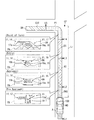
次に、一つの案内ポイントGP(案内交差点)の通過に伴う案内表示物11の状態遷移の詳細を、図2及び図3に基づき、図1を参照しつつ説明する。上述したように、TBT表示アプリ50eは、案内表示物11として、非重畳虚像12である交差点通知虚像13を一旦表示させた後、重畳虚像14であるレーン通知虚像15、減速通知虚像16、経路通知虚像17及び完了通知虚像を順に表示させる。案内表示物11として表示される各虚像Viには、共通する表示要素として、複数の経路線部18が描画されている。各経路線部18は、路面の幅方向に沿って線状に延伸する形状であり、走行経路DRとなる路面に沿って、互いに間隔を開けつつ並んでいる。
Next, the details of the state transition of the
交差点通知虚像13は、案内ポイントGPとしての案内交差点への接近を報知する案内表示物11である。交差点通知虚像13は、案内交差点の全体形状を示す交差点形状画像13aに、案内交差点からの退出方位を示す多数の経路線部18を組み合わせた態様で表示される。交差点通知虚像13は、非AR表示物であり、特定の重畳対象に重畳されない状態で、投影範囲PAの概ね全体に広がる大きさで、虚像表示される。
The intersection notification
交差点通知虚像13は、案内ポイントGPの手前に規定されるプレアプローチ区間PASにて、虚像表示される。プレアプローチ区間PASは、案内ポイントGPまでの残距離Lrが表示開始距離L1から切替距離L2までの区間である。表示開始距離L1は、例えば残距離Lrが700mとなる地点に設定される。切替距離L2は、例えば残距離Lrが300mとなる地点に設定される。交差点通知虚像13の表示は、残距離Lrが表示開始距離L1となったタイミングで開始され、表示開始から特定時間(数秒)が経過したタイミングで終了される。交差点通知虚像13の表示が切替距離L2まで継続されないのは、交差点通知虚像13によって投影範囲PAの全体が長時間覆われることを防ぐためである。
The intersection notification
TBT表示アプリ50eは、走行経路DRに沿って並ぶ複数の経路線部18を、手前(下)側から順に表示させるアニメーションの実施により、案内交差点での車両Aの移動方向を示す。TBT表示アプリ50eは、表示開始から特定時間が経過しタイミングにて、交差点通知虚像13の表示を終了する。特定時間は、経路線部18のアニメーションが一回、又は複数回表示させた後となるように、予め規定されている。こうしたアニメーションの繰り返し回数は、例えばDSMによるドライバのセンシング情報に基づいて変更可能である。一例として、投影範囲PAから目を離すようなドライバの脇見が検知された場合、TBT表示アプリ50eは、特定時間の延長により、アニメーションの繰り返し回数を増やすことができる。
The
レーン通知虚像15は、案内交差点への到達までに、ドライバが車両Aを移動させるべき推奨レーンを通知する案内表示物11である。レーン通知虚像15は、表示許可範囲UAに表示される。レーン通知虚像15は、路面画像15a及び方向通知画像15bを含んでいる。路面画像15aは、車両Aの前方路面に重畳されている。路面画像15aは、道路の幅方向に沿って直線状に延伸する複数の経路線部18によって表現されている。路面画像15aは、所定形状に描画される表示要素であり、案内交差点手前の道路形態に関わらず、実質一定の形状で表示される。
The lane notification
方向通知画像15bは、各経路線部18の上側又は下側に隣接表示される。方向通知画像15bは、経路線部18よりも短い長さで、経路線部18に沿って直線状に延伸している。方向通知画像15bの表示色は、路面画像15aの表示色とは異なっている。加えて、各経路線部18のうちで方向通知画像15bに望む一部は、方向通知画像15bと実質同一の表示色で表示される。
The
方向通知画像15bの路面画像15aに対する左右の相対位置は、案内交差点にて右左折等を行う方向であって、案内交差点までに車両Aを移動させる左右の方向を示している。即ち、案内交差点までに車両Aを右端のレーンに移動させる必要があるとき、方向通知画像15bは、路面画像15aの右端に表示される。一方で、案内交差点までに車両Aを左端のレーンに移動させる必要があるとき、方向通知画像15bは、路面画像15aの左端に表示される。
The left and right relative positions of the
レーン通知虚像15は、アプローチ区間ASにおいて表示される。アプローチ区間ASは、走行経路DRに沿ってプレアプローチ区間PASよりも案内ポイントGPに近い側に規定される。アプローチ区間ASは、案内ポイントGPまでの残距離Lrが切替距離L2から接近距離L3までの区間である。接近距離L3は、一例として、残距離Lrが100mとなる地点に設定される。レーン通知虚像15の表示は、残距離Lrが切替距離L2となったタイミングで開始され、残距離Lrが接近距離L3となるまで継続される。
The lane notification
減速通知虚像16は、案内交差点に進入する際の推奨速度を通知し、ドライバに減速を促す案内表示物11である。減速通知虚像16は、レーン通知虚像15と同様に、表示許可範囲UAに表示され、路面画像16a及び方向通知画像16bを含んでいる。路面画像16aは、路面画像15aとは異なり、V字形状とされた複数の経路線部18を有している。下凸状(又は上凸状)の各経路線部18よりなる路面画像16aは、車両Aの前方路面に重畳される。路面画像15aから路面画像16aへの形状変化により、減速通知虚像16は、案内交差点までの距離感を直感的にドライバに認知させる。方向通知画像16bは、路面画像16aと組み合わされて、案内ポイントGPまでに車両Aを移動させる左右の方向を継続的に示す。
The deceleration notification
減速通知虚像16は、車両Aの走行速度に基づき、案内交差点への進入速度が高すぎると判定した場合、走行速度の高さを注意喚起する態様に変更される。例えばTBT表示アプリ50eは、残距離Lrに対応する速度閾値を設定する。車両Aの走行速度が速度閾値を超えている場合、減速通知虚像16の表示色は、例えばレッド又はアンバー等に変更される。
The deceleration notification
減速通知虚像16は、進入区間ESにおいて表示される。進入区間ESは、走行経路DRに沿ってアプローチ区間ASよりも案内ポイントGPに近い側に規定される。進入区間ESは、案内ポイントGPまでの残距離Lrが接近距離L3から進入距離L4までの区間である。進入距離L4は、一例として、残距離Lrが30mとなる地点に設定される。減速通知虚像16の表示は、残距離Lrが接近距離L3となったタイミングで開始され、残距離Lrが進入距離L4となるまで継続される。
The deceleration notification
経路通知虚像17は、右左折等を行う案内交差点の位置及び案内交差点からの退出報知をドライバに報知する案内表示物11である。表示許可範囲UAの上方への拡張により、経路通知虚像17は、投影範囲PAの概ね全体を用いた表示とされる。経路通知虚像17は、減速通知虚像16から継続表示される路面画像16aと、経路画像17aとを含んでいる。経路画像17aは、路面画像16aの両側に配置され、走行経路DRに沿って帯状に延伸している。経路通知虚像17は、案内ポイントGPを含む前方路面に重畳されており、走行経路DRに従った経路画像17aの湾曲により、案内交差点からの退出方位を示している。
The route notification virtual image 17 is a
経路通知虚像17は、交差点範囲PTにおいて表示される。交差点範囲PTは、案内ポイントGPを含むように規定されている。交差点範囲PTは、案内ポイントGPまでの残距離Lrが進入距離L4から退出距離L5までのエリアである。退出距離L5は、一例として、残距離Lrがマイナス30mとなる地点、即ち、案内ポイントGPから退出方位に30mの地点に設定される。経路通知虚像17の表示は、残距離Lrが進入距離L4となったタイミングで開始され、残距離Lrが退出距離L5となるまで継続される。 The route notification virtual image 17 is displayed in the intersection range PT. The intersection range PT is defined to include the guide point GP. The intersection range PT is an area where the remaining distance Lr to the guide point GP is from the approach distance L4 to the exit distance L5. As an example, the exit distance L5 is set at a point where the remaining distance Lr is -30 m, that is, at a point 30 m in the exit direction from the guide point GP. The display of the route notification virtual image 17 is started at the timing when the remaining distance Lr becomes the approach distance L4, and continues until the remaining distance Lr becomes the exit distance L5.
完了通知虚像は、案内交差点での右左折の終了を通知する案内表示物11である。完了通知虚像は、前方路面に重畳される路面画像を含んでいる。路面画像として表示された複数の経路線部18を手前(下)側から順に表示させるアニメーションの実施により、完了通知虚像は、右左折が終了したことを通知しつつ、道路に沿った通常走行の開始をドライバに促す。完了通知虚像は、退出区間EXTにおいて表示される。退出区間EXTは、走行経路DRに沿って交差点範囲PTよりも案内ポイントGPから遠い側に規定される。完了通知虚像の表示は、残距離Lrが退出距離L5となったタイミングで表示され、アニメーションを所定回数繰り返したタイミングで終了される。
The completion notification virtual image is a
ここで、図4に示すような連続分岐が走行経路DRに生じた場合、TBT表示アプリ50eは、レーン通知虚像15及び減速通知虚像16の表示態様を変更可能である。TBT表示アプリ50eは、経路案内情報として、車両Aを走行させるべき推奨レーンをナビゲーション装置から取得可能である。TBT表示アプリ50eは、推奨レーンが取得できている場合、一つ目の案内ポイント(分岐点GP1)手前のアプローチ区間AS及び進入区間ESにて、通常の右左折時とは異なる表示形態のレーン通知虚像15及び減速通知虚像16を表示する。
Here, when a continuous branch as shown in FIG. 4 occurs in the traveling path DR, the
具体的に、TBT表示アプリ50eは、一つ目の分岐点GP1手前にて、路面画像15aの中央に方向通知画像15bを配置したレーン通知虚像15、及び路面画像16aの中央に方向通知画像16bを配置した減速通知虚像16、を順に表示させる。こうした表示形態のレーン通知虚像15及び減速通知虚像16を用いて、TBT表示アプリ50eは、右端のレーン(図4のβ参照)ではなく、中央のレーン(図4のα参照)への誘導を行う。以上の表示に従い、ドライバが車両Aを中央のレーンに移動させられていれば、二つ目の案内ポイント(分岐点GP2)での左折は、スムーズに実施され得る。
Specifically, the
ここまで説明した案内表示物11の表示を実現するために、表示制御装置100にて実施される表示制御処理の詳細を、図5に基づき、図1及び図2を参照しつつ、詳細に説明する。図5に示す表示制御処理は、例えばナビゲーション装置等におけるルート設定の完了等、特定イベントの発生をトリガとして開始される。
The details of the display control process performed by the
S101では、案内表示物11等の表示すべきコンテンツの有無を判定する。S101にて、表示すべきコンテンツがあると判定した場合、S102に進む。一方で、表示すべきコンテンツがないと判定した場合、S101の繰り返しにより、案内表示物11等のコンテンツの発生を待機する。
In S101, it is determined whether or not there is content to be displayed such as the
S102では、経路案内情報等を取得し、S103に進む。S102にて取得する経路案内情報には、認識情報、道路の走行環境情報等が含まれている。S103では、S102にて取得した経路案内情報のうちで、特に道路の走行環境情報に基づいて、各閾値距離(L1〜L5)を設定し、S104に進む。 In S102, route guidance information and the like are acquired, and the process proceeds to S103. The route guidance information acquired in S102 includes recognition information, road driving environment information, and the like. In S103, among the route guidance information acquired in S102, each threshold distance (L1 to L5) is set based on the driving environment information of the road, and the process proceeds to S104.
S104では、残距離Lrを把握すると共に、最新の残距離Lrが表示開始距離L1未満かを判定する。残距離Lrが表示開始距離L1以上である場合、S104の繰り返しにより、案内ポイントGPへの接近を待機する。そして、残距離Lrが表示開始距離L1未満となったタイミングにて、S105に進む。 In S104, the remaining distance Lr is grasped, and it is determined whether the latest remaining distance Lr is less than the display start distance L1. When the remaining distance Lr is equal to or greater than the display start distance L1, the approach to the guide point GP is awaited by repeating S104. Then, when the remaining distance Lr becomes less than the display start distance L1, the process proceeds to S105.
S105では、交差点通知虚像13を表示し、S106に進む。S106では、交差点通知虚像13の表示終了条件が成立したか否かを判定する。上述したように、表示開始からの経過時間又はアニメーションの繰り返し回数等が、交差点通知虚像13の表示終了条件として設定されている。S106にて、表示終了条件が成立したと判定した場合、S107に進む。
In S105, the intersection notification
S107では、残距離Lrと各閾値距離L2〜L5との比較が順に行われる。S107では、残距離Lrを把握すると共に、最新の残距離Lrが切替距離L2未満か否かを判定する。残距離Lrが切替距離L2以上である場合、S107の繰り返しによって案内ポイントGPへの接近を待機する。そして、残距離Lrが切替距離L2となったタイミングにて、S108に進む。 In S107, the remaining distance Lr and the threshold distances L2 to L5 are compared in order. In S107, the remaining distance Lr is grasped, and it is determined whether or not the latest remaining distance Lr is less than the switching distance L2. When the remaining distance Lr is the switching distance L2 or more, the approach to the guide point GP is awaited by repeating S107. Then, at the timing when the remaining distance Lr becomes the switching distance L2, the process proceeds to S108.
S108では、S102にて取得した認識情報に基づき、前走車の有無及び前方の道路形状に対応した表示許可範囲UAを設定し、S109に進む。S108にて設定される表示許可範囲UAのサイズは、繰り返し回数の増加に伴って大きくされる。S109では、レーン通知虚像15の表示を開始し、S110に進む。以上のS107〜S109の繰り返しにより、重畳虚像14は、レーン通知虚像15、減速通知虚像16、経路通知虚像17及び完了通知虚像へと、順に切り替えられる。
In S108, based on the recognition information acquired in S102, the display permission range UA corresponding to the presence / absence of the vehicle in front and the shape of the road ahead is set, and the process proceeds to S109. The size of the display permission range UA set in S108 is increased as the number of repetitions increases. In S109, the display of the lane notification
S110では、重畳虚像14の消去条件が成立したか否かを判定する。消去条件は、予め設定された条件であり、例えば案内交差点からの所定距離以上離れた、完了通知虚像の表示開始から所定時間が経過した、及び車両Aが走行経路DRから外れた等である。S110にて、消去条件が成立していないと判定した場合、S107に戻る。その結果、次の閾値距離と残距離Lrとの比較が実施される。一方で、S110にて、消去条件が成立したと判定した場合、S111に進む。S111では、重畳虚像14の表示をオフし、表示制御処理を終了する。
In S110, it is determined whether or not the erasing condition of the superimposed
ここまで説明した本実施形態では、案内ポイントGPまでの残距離Lrが切替距離L2よりも長い段階では、非重畳虚像12が表示される。故に、案内ポイントGPは、案内表示物11によって明示されない。その結果、遠方に位置し、知覚し難い案内ポイントGPを無理に認識するようなタスクの発生が防がれ得る。
In the present embodiment described so far, the non-superimposed virtual image 12 is displayed at the stage where the remaining distance Lr to the guide point GP is longer than the switching distance L2. Therefore, the guidance point GP is not specified by the
そして、案内ポイントGPまでの残距離Lrが切替距離L2よりも短くなった段階で、重畳虚像14が案内表示物11として表示される。こうした虚像表示の変化によれば、重畳対象の認識が容易となったタイミングにて、案内表示物11は、重畳対象にドライバの注意を向けさせることができる。その結果、虚像表示は、スムーズな運転ができるようにドライバを支援可能となる。
Then, when the remaining distance Lr to the guide point GP becomes shorter than the switching distance L2, the superimposed
加えて本実施形態の領域制限部52は、重畳虚像14の表示を許容する表示許可範囲UAを投影範囲PAの一部に制限する。こうした表示範囲の制限によれば、HUD装置30の画角のうちで、重畳対象から重畳虚像14がずれ易い領域は、AR表示に使用されなくなる。故に、重畳虚像14の重畳ずれに起因するドライバの違和感は、生じ難くなる。
In addition, the
また本実施形態では、投影範囲PAのうちの下方寄りの範囲に表示許可範囲UAが規定される。そのためレーン通知虚像15及び減速通知虚像16等の重畳虚像14は、車両A姿勢変化や道路形状等に関わらず、前方路面と重なる可能性が高い位置に描画される。以上のような表示範囲の制限によれば、勾配及びカーブ等の道路形状を要因とした重畳ずれ、並びに重畳虚像14による前走車の遮蔽等が生じ難くなる。
Further, in the present embodiment, the display permission range UA is defined in the lower range of the projection range PA. Therefore, the superposed
さらに本実施形態では、案内ポイントGPまでの残距離Lrが短い交差点範囲PTでは、残距離Lrが長いアプローチ区間AS及び進入区間ESと比較して、領域制限部52は、表示許可範囲UAを大きく規定する。以上のような表示許可範囲UAの調整制御によれば、表示制御部53は、重畳ずれを生じ易い領域が減少した段階で、大きな重畳虚像14を表示し得る。故に、重畳虚像14による情報提示は、いっそうドライバに分かり易くなる。
Further, in the present embodiment, in the intersection range PT having a short remaining distance Lr to the guide point GP, the
加えて本実施形態では、車両前方の認識情報に基づき、表示許可範囲UAが変更される。故に、表示制御部53は、道路形状及び前走車の有無等、前方範囲の状態に最適な重畳虚像14を、適宜表示可能となる。その結果、重畳虚像14による情報提示は、いっそうドライバに分かり易くなる。
In addition, in the present embodiment, the display permission range UA is changed based on the recognition information in front of the vehicle. Therefore, the
また本実施形態では、案内ポイントGPまでの残距離Lrに基づき、重畳虚像14の態様が、順に変更される。こうした重畳虚像14の状態遷移によれば、案内ポイントGPまでの残距離Lrが直接的に虚像表示されなくても、ドライバは、案内ポイントGPまでの残距離Lrを、直感的に認知し得る。以上によれば、残距離Lrに対応する運転行動がドライバに示唆され得るため、レーン移動及び減速等のドライバによる運転操作は、いっそうスムーズに行われる。
Further, in the present embodiment, the aspect of the superimposed
さらに本実施形態のレーン通知虚像15において、路面画像15aは、車両前方の道路形状に実質関係なく、常に所定の形状で表示される。故に、自車が走行中の道路のレーン数、走行中のレーン位置、レーンの拡張位置等が不明であっても、TBT表示アプリ50eは、レーン通知虚像15を描画できる。したがって、高精度位置情報及び高精度マップ情報の取得が困難な場合でも、案内表示物11は、スムーズなレーン移動をドライバに促すことができる。
Further, in the lane notification
加えて方向通知画像15bは、所定形状の路面画像15aに対する左右の相対位置により、車両Aを移動させるべき左右の方向、ひいては案内ポイントGPでの退出方位を示すことができる。このように、レーン通知虚像15は、ドライバに望む運転行動を、シンプルな表示によって分かり易く伝えることができる。
In addition, the
また本実施形態では、進入区間ESへの進入に伴う減速通知虚像16の表示により、適切なタイミングでドライバに減速が促される。加えて減速通知虚像16は、進入時における走行速度の高さを注意喚起できる。以上によれば、減速通知虚像16は、案内ポイントGPへのムーズな進入の実施を支援できる。
Further, in the present embodiment, the driver is urged to decelerate at an appropriate timing by displaying the deceleration notification
さらに本実施形態では、車両Aの交差点範囲PTへの進入により、案内ポイントGPを含む前方路面に、退出方位を示す経路通知虚像17が表示される。以上のように、退出方位を示す経路通知虚像17の表示タイミングを、案内交差点近傍の交差点範囲PTへの到達まで遅らせることによれば、経路通知虚像17によって示される退出方位は、案内ポイントGPからの退出先となる道路を、精度良く指し示し得る。故に、経路通知虚像17を視認するドライバは、退出先となる道路を認識したうえで、案内ポイントGPでの右左折等をスムーズに行うことができる。 Further, in the present embodiment, when the vehicle A enters the intersection range PT, a route notification virtual image 17 indicating the exit direction is displayed on the front road surface including the guide point GP. As described above, by delaying the display timing of the route notification virtual image 17 indicating the exit direction until reaching the intersection range PT near the guide intersection, the exit direction indicated by the route notification virtual image 17 is from the guide point GP. It is possible to accurately point to the road to which you will leave. Therefore, the driver who visually recognizes the route notification virtual image 17 can smoothly turn left or right at the guidance point GP after recognizing the road to be exited.
加えて本実施形態の表示制御部53は、走行環境情報として取得する道路の種別情報及び混雑情報等に基づき、表示開始距離L1〜退出距離L5の各値を調整できる。こうした調整によれば、表示制御部53は、実際の道路環境に応じて、運転者の運転行動が必要とされるタイミングで、交差点通知虚像13及びレーン通知虚像15〜経路通知虚像17を逐次表示させていく。その結果、ドライバは、車両Aの走行環境に関わらず、情報提示に基づきスムーズな運転操作を行い得る。
In addition, the
尚、上記実施形態では、統合表示制御ブロック73が「表示生成部」に相当し、投影範囲PAが「表示可能領域」に相当する。
In the above embodiment, the integrated
(他の実施形態)
以上、本開示の一実施形態について説明したが、本開示は、上記実施形態に限定して解釈されるものではなく、本開示の要旨を逸脱しない範囲内において種々の実施形態及び組み合わせに適用することができる。
(Other embodiments)
Although one embodiment of the present disclosure has been described above, the present disclosure is not construed as being limited to the above embodiment, and is applied to various embodiments and combinations within the scope of the gist of the present disclosure. be able to.
上記実施形態での非重畳虚像の表示は、残距離が切替距離になる以前に終了されていた。このように、案内表示物を非重畳虚像から重畳虚像へと切り替える間に、表示の中断期間が設定されていてもよい。また、非重畳虚像の表示は、残距離が切替距離になるまで継続されてもよい。こうした形態では、案内表示物は、交差点通知虚像からレーン通知虚像へと直接的に切り替えられる。 The display of the non-superimposed virtual image in the above embodiment was terminated before the remaining distance became the switching distance. In this way, a display interruption period may be set while the guide display object is switched from the non-superimposed virtual image to the superposed virtual image. Further, the display of the non-superimposed virtual image may be continued until the remaining distance reaches the switching distance. In such a form, the guide display is directly switched from the intersection notification virtual image to the lane notification virtual image.
上記実施形態では、案内ポイントの近傍において、HUD装置により表示される虚像表示物は、案内表示物のみであった。しかし、案内表示物以外の虚像表示物が、案内ポイントの近傍で表示されてよい。例えば、プレアプローチ区間において、道路標識及び歩行者等を注意喚起する重畳虚像が、交差点通知虚像と共に表示されてもよい。加えて、切替距離よりも案内交差点に近い区間において、交差点通知虚像を縮小させたアイコン形態の非重畳虚像が、案内表示物として表示される重畳虚像の周囲に、補足的に表示されていてもよい。 In the above embodiment, the virtual image display object displayed by the HUD device in the vicinity of the guide point is only the guide display object. However, a virtual image display object other than the guide display object may be displayed in the vicinity of the guide point. For example, in the pre-approach section, a road sign and a superposed virtual image that calls attention to pedestrians and the like may be displayed together with an intersection notification virtual image. In addition, in the section closer to the guide intersection than the switching distance, even if the non-superimposed virtual image in the form of an icon obtained by reducing the intersection notification virtual image is supplementarily displayed around the superimposed virtual image displayed as the guide display object. Good.
上記実施形態では、案内ポイントまでの残距離に応じて、重畳虚像は、レーン通知虚像、減速通知虚像、経路通知虚像及び完了通知虚像へと、順に切り替えられていた。こうした重畳虚像の数、及び個々の重畳虚像の表示継続時間等は、適宜変更されてよい。さらに、各重畳虚像によって通知される情報、各重畳虚像の形状等も、適宜変更されてよい。また、完了通知虚像は、重畳虚像ではなく、非重畳虚像として表示されてもよい。加えて、DSMによるドライバのセンシング情報に基づき、ドライバによる表示物の見逃しが推定される場合には、非重畳虚像及び重畳虚像の再表示が実施されてもよい。 In the above embodiment, the superimposed virtual image is sequentially switched to a lane notification virtual image, a deceleration notification virtual image, a route notification virtual image, and a completion notification virtual image according to the remaining distance to the guide point. The number of such superimposed virtual images, the display duration of each superimposed virtual image, and the like may be changed as appropriate. Further, the information notified by each superimposed virtual image, the shape of each superimposed virtual image, and the like may be changed as appropriate. Further, the completion notification virtual image may be displayed as a non-superimposed virtual image instead of a superposed virtual image. In addition, if it is estimated that the display object is overlooked by the driver based on the driver's sensing information by DSM, the non-superimposed virtual image and the superposed virtual image may be redisplayed.
上記実施形態では、アプローチ区間及び進入区間における表示許可範囲が投影範囲の一部に制限されていた。こうした表示範囲を制限する制御の詳細は、適宜変更されてよい。例えば、進入区間における表示許可範囲は、アプローチ区間における表示許可範囲より大きくされていてもよい。また、表示許可範囲は、残距離の減少に伴って連続的に拡大されてもよい。さらに、表示許可範囲を設定する処理は、実施されてなくてもよい。 In the above embodiment, the display permission range in the approach section and the approach section is limited to a part of the projection range. The details of the control that limits the display range may be changed as appropriate. For example, the display permission range in the approach section may be larger than the display permission range in the approach section. Further, the display permission range may be continuously expanded as the remaining distance decreases. Further, the process of setting the display permission range may not be performed.
加えて、表示許可範囲の初期の形状及び位置、拡張方向等も、適宜変更されてよい。例えば、表示許可範囲は、案内ポイントへの接近に伴い、退出方位へ向けて横方向に拡張されてもよい。さらに、表示許可範囲は、残距離及び認識情報とは異なるパラメータに基づいて大きさを変更されてもよい。 In addition, the initial shape and position of the display permission range, the expansion direction, and the like may be changed as appropriate. For example, the display permission range may be expanded laterally toward the exit direction as the guide point is approached. Further, the display permission range may be resized based on parameters different from the remaining distance and the recognition information.
上記実施形態では、案内表示物の消去条件の一つとして、走行経路からの離脱の検知が設定されていた(図5 S110参照)。こうした消去条件として、走行経路からの離脱の兆候の検知が設定されていてもよい。詳記すると、高精度位置情報及び高精度マップ情報を共に取得できている場合、表示制御装置は、案内ポイント手前での車両の走行レーンがルート情報に基づく推奨レーンと一致しているか否かを判定できる。表示制御装置は、走行中のレーンが推奨レーンと異なる場合、車両が走行経路から離脱すると推定する。以上の推定に基づき、表示制御装置は、前景の視認を妨げ得る重畳虚像の表示を、早期に終了させる。 In the above embodiment, detection of departure from the traveling route is set as one of the conditions for erasing the guidance display object (see FIG. 5S110). As such an erasing condition, detection of a sign of departure from the traveling route may be set. In detail, when both high-precision position information and high-precision map information can be acquired, the display control device determines whether or not the traveling lane of the vehicle in front of the guidance point matches the recommended lane based on the route information. Can be judged. The display control device estimates that the vehicle will leave the travel path if the traveling lane is different from the recommended lane. Based on the above estimation, the display control device ends the display of the superimposed virtual image that may hinder the visibility of the foreground at an early stage.
上記実施形態の表示制御部は、走行環境情報に基づき、各閾値距離を変更していた。こうした各閾値距離の変更制御の詳細は、適宜変更可能である。例えば、複数の閾値距離のうちで、特定の閾値距離(例えば切替距離)が、走行環境情報に基づく調整の対象から外されていてもよい。こうした形態では、案内ポイントまでの残距離が切替距離となる一定の位置で、重畳虚像の表示が開示される。その結果、一部のドライバは、表示遷移のタイミングが調整されてしまうよりも、運転操作のリズムを掴み易くなり得る。さらに、各閾値距離の変更制御は、実施されなくてもよい。 The display control unit of the above embodiment changes each threshold distance based on the traveling environment information. The details of the change control of each threshold distance can be changed as appropriate. For example, among a plurality of threshold distances, a specific threshold distance (for example, a switching distance) may be excluded from the adjustment target based on the traveling environment information. In such a form, the display of the superimposed virtual image is disclosed at a fixed position where the remaining distance to the guide point is the switching distance. As a result, some drivers may find it easier to grasp the rhythm of the driving operation rather than adjusting the timing of the display transition. Further, the change control of each threshold distance does not have to be performed.
ドライバ等の乗員が設定変更に用いる入力インターフェースは、上記実施形態のようなタッチパネル及びステアリングスイッチ等に限定されない。例えば、音声及びジェスチャーの少なくとも一方による入力をユーザの操作として、表示許可範囲及び各閾値距離等の設定が切り替えられてもよい。尚、乗員による設定変更は、許可されていなくてもよい。 The input interface used by the occupant such as a driver to change the setting is not limited to the touch panel, the steering switch, and the like as in the above embodiment. For example, the setting of the display permission range, each threshold distance, and the like may be switched by inputting at least one of voice and gesture as a user operation. The setting change by the occupant may not be permitted.
HUD装置は、例えば異なる位置に遠虚像及び近虚像を結像させる二焦点方式の投影装置であってもよい。このようなHUD装置では、上記の非重畳虚像及び重畳虚像は、遠虚像として表示される表示物に相当する。 The HUD device may be, for example, a bifocal projection device that forms a far virtual image and a near virtual image at different positions. In such a HUD device, the non-superimposed virtual image and the superposed virtual image correspond to a display object displayed as a distant virtual image.
HUD装置の光学的な構成は、適宜変更可能である。例えばプロジェクタには、レーザ光源及びMEMSスキャナ等を含む構成が採用されていてもよい。或いは、DMD(Digital Micromirror Device)を用いたDLP(Digital Light Processing,登録商標)が、プロジェクタに採用されてもよい。さらに、LCOS(Liquid Crystal On Silicon)等を用いたプロジェクタ、液晶パネル及びLED光源を有する液晶プロジェクタ等が、HUD装置に採用可能である。 The optical configuration of the HUD device can be changed as appropriate. For example, the projector may have a configuration including a laser light source, a MEMS scanner, and the like. Alternatively, DLP (Digital Light Processing, a registered trademark) using a DMD (Digital Micromirror Device) may be adopted for the projector. Further, a projector using LCOS (Liquid Crystal On Silicon) or the like, a liquid crystal panel, a liquid crystal projector having an LED light source, or the like can be adopted for the HUD device.
上記実施形態の表示制御装置は、HUD装置とは別体の電子制御ユニットとして設けられていた。しかし、上記表示制御装置の各機能は、例えばHUD装置に設けられた制御回路に実装されていてもよく、又はコンビネーションメータに設けられた制御回路等に実装されていてもよい。 The display control device of the above embodiment is provided as an electronic control unit separate from the HUD device. However, each function of the display control device may be mounted on, for example, a control circuit provided in the HUD device, or may be mounted in a control circuit provided in the combination meter or the like.
さらに、上記実施形態にて表示制御装置の制御回路により提供された各機能は、ソフトウェア及びそれを実行するハードウェア、ソフトウェアのみ、ハードウェアのみ、あるいはそれらの複合的な組合せによっても提供可能である。こうした機能がハードウェアである電子回路によって提供される場合、各機能は、多数の論理回路を含むデジタル回路、又はアナログ回路によっても提供可能である。 Further, each function provided by the control circuit of the display control device in the above embodiment can be provided by the software and the hardware for executing the software, the hardware only, the hardware only, or a combination thereof. .. When such a function is provided by an electronic circuit which is hardware, each function can also be provided by a digital circuit including a large number of logic circuits or an analog circuit.
表示制御プログラム等を記憶するメモリ装置等には、フラッシュメモリ及びハードディスク等の種々の非遷移的実体的記憶媒体(non-transitory tangible storage medium)が採用可能である。こうした記憶媒体の形態も、適宜変更されてよい。例えば記憶媒体は、メモリカード等の形態であり、表示制御装置に設けられたスロット部に挿入されて、制御回路に電気的に接続される構成であってよい。さらに記憶媒体は、上述のような車載装置のメモリ装置に限定されず、当該メモリ装置へのプログラムのコピー基となる光学ディスク及び汎用コンピュータのハードディスクドライブ等であってもよい。 Various non-transitory tangible storage media such as flash memory and hard disk can be adopted as a memory device or the like for storing a display control program or the like. The form of such a storage medium may also be changed as appropriate. For example, the storage medium may be in the form of a memory card or the like, and may be inserted into a slot portion provided in the display control device and electrically connected to the control circuit. Further, the storage medium is not limited to the memory device of the in-vehicle device as described above, and may be an optical disk as a copy base of the program to the memory device, a hard disk drive of a general-purpose computer, or the like.
A 車両、DR 走行経路、AS アプローチ区間、ES 進入区間、GP 案内ポイント、Lr 残距離、L2 切替距離、PA 投影範囲(表示可能領域)、UA 表示許可範囲、Vi 虚像、11 案内表示物、12 非重畳虚像、14 重畳虚像、15 レーン通知虚像、15a 路面画像、15b 方向通知画像、16 減速通知虚像、17 経路通知虚像、51 距離把握部、52 領域制限部、53 表示制御部、61 処理部、73 統合表示制御ブロック(表示生成部)、100 表示制御装置 A vehicle, DR travel route, AS approach section, ES approach section, GP guide point, Lr remaining distance, L2 switching distance, PA projection range (displayable area), UA display permission range, Vi virtual image, 11 guide display, 12 Non-superimposed virtual image, 14 superposed virtual image, 15 lane notification virtual image, 15a road surface image, 15b direction notification image, 16 deceleration notification virtual image, 17 route notification virtual image, 51 distance grasping unit, 52 area limiting unit, 53 display control unit, 61 processing unit , 73 Integrated display control block (display generator), 100 Display control device
Claims (11)
前記車両の走行経路(DR)を前記乗員に案内する案内表示物(11)を生成する表示生成部(73)と、
前記案内表示物による経路案内が生じる案内ポイント(GP)までの残距離(Lr)を把握する距離把握部(51)と、
前記車両から前記案内ポイントまでの前記残距離が切替距離(L2)よりも長い場合に、特定の重畳対象には重畳されない非重畳虚像(12)を前記案内表示物として表示させ、前記案内ポイントまでの前記残距離が前記切替距離よりも短くなると、特定の重畳対象に重畳される重畳虚像(14)を表示させる表示制御部(53)と、
前記重畳虚像の表示を許容する表示許可範囲(UA)を、前記虚像を表示可能な表示可能領域(PA)の一部に制限する領域制限部(52)と、を備え、
前記領域制限部は、前記案内ポイントまでの前記残距離が短いほど前記表示許可範囲を大きく規定する表示制御装置。 A display control device used in a vehicle (A) that controls the display of a virtual image (Vi) visually recognized by the occupants of the vehicle.
A display generation unit (73) that generates a guidance display object (11) that guides the traveling route (DR) of the vehicle to the occupant.
A distance grasping unit (51) for grasping the remaining distance (Lr) to the guide point (GP) where the route guidance by the guide display object occurs, and
When the remaining distance from the vehicle to the guide point is longer than the switching distance (L2), a non-superimposed virtual image (12) that is not superposed on a specific superimposition target is displayed as the guide display object to reach the guide point. wherein when the remaining distance is shorter than the switching distance, the display control unit for displaying the superimposed virtual image (14) superimposed on the superimposition target of specific (53),
A display permission range (UA) that allows the display of the superimposed virtual image is provided with an area limiting unit (52) that limits the displayable virtual image to a part of the displayable area (PA) that can display the virtual image .
The region limiting unit, the remaining distance to the guidance point you define increase the display permission range shorter display control device.
前記車両の走行経路(DR)を前記乗員に案内する案内表示物(11)を生成する表示生成部(73)と、
前記案内表示物による経路案内が生じる案内ポイント(GP)までの残距離(Lr)を把握する距離把握部(51)と、
前記車両から前記案内ポイントまでの前記残距離が切替距離(L2)よりも長い場合に、特定の重畳対象には重畳されない非重畳虚像(12)を前記案内表示物として表示させ、前記案内ポイントまでの前記残距離が前記切替距離よりも短くなると、特定の重畳対象に重畳される重畳虚像(14)を表示させる表示制御部(53)と、
前記重畳虚像の表示を許容する表示許可範囲(UA)を、前記虚像を表示可能な表示可能領域(PA)の一部に制限する領域制限部(52)と、を備え、
前記領域制限部は、前記表示可能領域の下側に前記表示許可範囲を規定し、前記表示許可範囲を上方に拡大させる表示制御装置。 A display control device used in a vehicle (A) that controls the display of a virtual image (Vi) visually recognized by the occupants of the vehicle.
A display generation unit (73) that generates a guidance display object (11) that guides the traveling route (DR) of the vehicle to the occupant.
A distance grasping unit (51) for grasping the remaining distance (Lr) to the guide point (GP) where the route guidance by the guide display object occurs, and
When the remaining distance from the vehicle to the guide point is longer than the switching distance (L2), a non-superimposed virtual image (12) that is not superposed on a specific superimposition target is displayed as the guide display object to reach the guide point. wherein when the remaining distance is shorter than the switching distance, the display control unit for displaying the superimposed virtual image (14) superimposed on the superimposition target of specific (53),
A display permission range (UA) that allows the display of the superimposed virtual image is provided with an area limiting unit (52) that limits the displayable virtual image to a part of the displayable area (PA) that can display the virtual image .
The region limiting unit, the displayable defining the display permission range in the lower region, the display permission range display controller Ru is enlarged upwardly.
前記レーン通知虚像は、前記車両の前方路面に重畳される所定形状の路面画像(15a)と、前記路面画像に対する左右の相対位置により前記案内ポイントまでに前記車両を移動させる左右の方向を示す方向通知画像(15b)と、を含む請求項5に記載の表示制御装置。 The display control unit displays a lane notification virtual image (15) as the superimposed virtual image in an approach section (AS) defined along the traveling route and closer to the guide point than the switching distance.
The lane notification virtual image is a direction indicating a left-right direction in which the vehicle is moved to the guide point by a road surface image (15a) having a predetermined shape superimposed on the road surface in front of the vehicle and a left-right relative position with respect to the road surface image. The display control device according to claim 5 , which includes a notification image (15b).
前記減速通知虚像は、前記車両の走行速度に基づき、当該走行速度の高さを注意喚起する態様に変更される請求項6に記載の表示制御装置。 The display control unit superimposes the deceleration notification virtual image (16) superimposed on the front road surface in the approach section (ES) defined along the traveling path closer to the guide point than the approach section. Display as a virtual image
The display control device according to claim 6 , wherein the deceleration notification virtual image is changed to a mode for calling attention to the height of the traveling speed based on the traveling speed of the vehicle.
前記経路通知虚像は、前記案内ポイントを含む前記前方路面に重畳され、前記案内ポイントからの退出方位を示す請求項7に記載の表示制御装置。 The display control unit displays a route notification virtual image (17) as the superimposed virtual image when the vehicle is closer to the guide point than the approach section.
The display control device according to claim 7 , wherein the route notification virtual image is superimposed on the front road surface including the guide point and indicates an exit direction from the guide point.
少なくとも一つの処理部(61)を、
前記車両の走行経路(DR)を前記乗員に案内する案内表示物(11)を生成する表示生成部(73)、
前記案内表示物による経路案内が生じる案内ポイント(GP)までの残距離(Lr)を把握する距離把握部(51)、
前記車両から前記案内ポイントまでの前記残距離が切替距離(L2)よりも長い場合に、特定の重畳対象には重畳されない非重畳虚像(12)を前記案内表示物として表示させ、前記案内ポイントまでの前記残距離が前記切替距離よりも短くなると、特定の重畳対象に重畳される重畳虚像(14)を表示させる表示制御部(53)、
前記重畳虚像の表示を許容する表示許可範囲(UA)を、前記虚像を表示可能な表示可能領域(PA)の一部に制限する領域制限部(52)、として機能させ、
前記領域制限部は、前記案内ポイントまでの前記残距離が短いほど前記表示許可範囲を大きく規定する表示制御プログラム。 A display control program used in a vehicle (A) to control the display of a virtual image (Vi) visible to the occupants of the vehicle.
At least one processing unit (61)
A display generation unit (73) that generates a guidance display object (11) that guides the traveling route (DR) of the vehicle to the occupant.
Distance grasping unit (51) for grasping the remaining distance (Lr) to the guidance point (GP) where the route guidance by the guidance display object occurs,
When the remaining distance from the vehicle to the guide point is longer than the switching distance (L2), a non-superimposed virtual image (12) that is not superposed on a specific superimposition target is displayed as the guide display object to reach the guide point. wherein when the remaining distance is shorter than the switching distance, the display control unit for displaying the superimposed virtual image (14) superimposed on the superimposition target of a specific (53),
The display permitted range (UA) that allows the display of the superimposed virtual image is made to function as an area limiting unit (52) that limits the displayable virtual image to a part of the displayable area (PA) .
The region limiting unit, the remaining distance is shorter the display permission range largely defined to that display control program to said guide point.
少なくとも一つの処理部(61)を、
前記車両の走行経路(DR)を前記乗員に案内する案内表示物(11)を生成する表示生成部(73)、
前記案内表示物による経路案内が生じる案内ポイント(GP)までの残距離(Lr)を把握する距離把握部(51)、
前記車両から前記案内ポイントまでの前記残距離が切替距離(L2)よりも長い場合に、特定の重畳対象には重畳されない非重畳虚像(12)を前記案内表示物として表示させ、前記案内ポイントまでの前記残距離が前記切替距離よりも短くなると、特定の重畳対象に重畳される重畳虚像(14)を表示させる表示制御部(53)、
前記重畳虚像の表示を許容する表示許可範囲(UA)を、前記虚像を表示可能な表示可能領域(PA)の一部に制限する領域制限部(52)、として機能させ、
前記領域制限部は、前記表示可能領域の下側に前記表示許可範囲を規定し、前記表示許可範囲を上方に拡大させる表示制御プログラム。 A display control program used in a vehicle (A) to control the display of a virtual image (Vi) visible to the occupants of the vehicle.
At least one processing unit (61)
A display generation unit (73) that generates a guidance display object (11) that guides the traveling route (DR) of the vehicle to the occupant.
Distance grasping unit (51) for grasping the remaining distance (Lr) to the guidance point (GP) where the route guidance by the guidance display object occurs,
When the remaining distance from the vehicle to the guide point is longer than the switching distance (L2), a non-superimposed virtual image (12) that is not superposed on a specific superimposition target is displayed as the guide display object to reach the guide point. wherein when the remaining distance is shorter than the switching distance, the display control unit for displaying the superimposed virtual image (14) superimposed on the superimposition target of a specific (53),
The display permitted range (UA) that allows the display of the superimposed virtual image is made to function as an area limiting unit (52) that limits the displayable virtual image to a part of the displayable area (PA) .
The region limiting unit is configured to define the display permission range below the display area, the display permission range Ru display control program is expanded upward.
Priority Applications (3)
| Application Number | Priority Date | Filing Date | Title |
|---|---|---|---|
| JP2018102457A JP6836206B2 (en) | 2018-05-29 | 2018-05-29 | Display control device and display control program |
| PCT/JP2019/017331 WO2019230272A1 (en) | 2018-05-29 | 2019-04-24 | Display control device, display control program, and persistent tangible computer-readable recording medium therefor |
| US17/101,757 US20210104212A1 (en) | 2018-05-29 | 2020-11-23 | Display control device, and nontransitory tangible computer-readable medium therefor |
Applications Claiming Priority (1)
| Application Number | Priority Date | Filing Date | Title |
|---|---|---|---|
| JP2018102457A JP6836206B2 (en) | 2018-05-29 | 2018-05-29 | Display control device and display control program |
Publications (3)
| Publication Number | Publication Date |
|---|---|
| JP2019207155A JP2019207155A (en) | 2019-12-05 |
| JP2019207155A5 JP2019207155A5 (en) | 2020-05-21 |
| JP6836206B2 true JP6836206B2 (en) | 2021-02-24 |
Family
ID=68696949
Family Applications (1)
| Application Number | Title | Priority Date | Filing Date |
|---|---|---|---|
| JP2018102457A Active JP6836206B2 (en) | 2018-05-29 | 2018-05-29 | Display control device and display control program |
Country Status (3)
| Country | Link |
|---|---|
| US (1) | US20210104212A1 (en) |
| JP (1) | JP6836206B2 (en) |
| WO (1) | WO2019230272A1 (en) |
Families Citing this family (8)
| Publication number | Priority date | Publication date | Assignee | Title |
|---|---|---|---|---|
| WO2021091039A1 (en) * | 2019-11-06 | 2021-05-14 | 엘지전자 주식회사 | Display device for vehicle and control method therefor |
| WO2021132554A1 (en) * | 2019-12-27 | 2021-07-01 | 日本精機株式会社 | Navigation device, navigation device control method, and navigation device control program |
| WO2021149740A1 (en) | 2020-01-24 | 2021-07-29 | Ricoh Company, Ltd. | Display apparatus, movable body, display method, program, and non-transitory recording medium |
| JP7423341B2 (en) * | 2020-02-19 | 2024-01-29 | 本田技研工業株式会社 | Control device, vehicle, program, and control method |
| JP2022184350A (en) * | 2021-06-01 | 2022-12-13 | マツダ株式会社 | head-up display device |
| TW202301078A (en) * | 2021-06-29 | 2023-01-01 | 微馳智電股份有限公司 | System for intuitive human-machine interface |
| JP2023012793A (en) * | 2021-07-14 | 2023-01-26 | 株式会社アイシン | Superimposed image display device |
| US20230290156A1 (en) * | 2022-03-11 | 2023-09-14 | GM Global Technology Operations LLC | System and method for providing lane identification on an augmented reality display |
Family Cites Families (8)
| Publication number | Priority date | Publication date | Assignee | Title |
|---|---|---|---|---|
| JP2005297810A (en) * | 2004-04-13 | 2005-10-27 | Denso Corp | Display system for vehicle and program |
| JP2014201197A (en) * | 2013-04-04 | 2014-10-27 | トヨタ自動車株式会社 | Head-up display apparatus |
| JP6273976B2 (en) * | 2014-03-31 | 2018-02-07 | 株式会社デンソー | Display control device for vehicle |
| JP2016052837A (en) * | 2014-09-04 | 2016-04-14 | 日本精機株式会社 | Head-up display device |
| JP2016137736A (en) * | 2015-01-26 | 2016-08-04 | 三菱電機株式会社 | Image display device |
| JP2017053678A (en) * | 2015-09-08 | 2017-03-16 | アイシン・エィ・ダブリュ株式会社 | Travel support system, travel support method and computer program |
| EP3357782B1 (en) * | 2015-09-30 | 2020-08-05 | Nissan Motor Co., Ltd. | Information presenting device and information presenting method |
| JP6361794B2 (en) * | 2017-07-07 | 2018-07-25 | 日本精機株式会社 | Vehicle information projection system |
-
2018
- 2018-05-29 JP JP2018102457A patent/JP6836206B2/en active Active
-
2019
- 2019-04-24 WO PCT/JP2019/017331 patent/WO2019230272A1/en active Application Filing
-
2020
- 2020-11-23 US US17/101,757 patent/US20210104212A1/en not_active Abandoned
Also Published As
| Publication number | Publication date |
|---|---|
| US20210104212A1 (en) | 2021-04-08 |
| WO2019230272A1 (en) | 2019-12-05 |
| JP2019207155A (en) | 2019-12-05 |
Similar Documents
| Publication | Publication Date | Title |
|---|---|---|
| JP6836206B2 (en) | Display control device and display control program | |
| JP7017154B2 (en) | Display control device and display control program | |
| JP7063316B2 (en) | Display control device and display control program | |
| JP6241093B2 (en) | Head-up display device | |
| JP6528139B2 (en) | Display control device and display control program | |
| JP6303428B2 (en) | Vehicle information projection system | |
| JP6866875B2 (en) | Display control device and display control program | |
| JP7218822B2 (en) | display controller | |
| WO2020261781A1 (en) | Display control device, display control program, and persistent tangible computer-readable medium | |
| US20220118983A1 (en) | Display control device and display control program product | |
| CN113784861B (en) | Display control method and display control device | |
| US20230221569A1 (en) | Virtual image display device and display system | |
| US11850940B2 (en) | Display control device and non-transitory computer-readable storage medium for display control on head-up display | |
| JP6933189B2 (en) | Display control device and display control program | |
| JP2015120395A (en) | Vehicle information projection system | |
| WO2022209439A1 (en) | Virtual image display device | |
| JP2018020779A (en) | Vehicle information projection system | |
| JP2015074391A (en) | Head-up display device | |
| JP6631572B2 (en) | Display control device for vehicle and display unit for vehicle | |
| JP7310560B2 (en) | Display control device and display control program | |
| JP2020095044A (en) | Display controller and display control method | |
| JP7318431B2 (en) | Display control device and display control program | |
| JP6610376B2 (en) | Display device | |
| JP2019207632A (en) | Display device | |
| JP7259802B2 (en) | Display control device, display control program and in-vehicle system |
Legal Events
| Date | Code | Title | Description |
|---|---|---|---|
| A521 | Request for written amendment filed |
Free format text: JAPANESE INTERMEDIATE CODE: A523 Effective date: 20200410 |
|
| A621 | Written request for application examination |
Free format text: JAPANESE INTERMEDIATE CODE: A621 Effective date: 20200410 |
|
| TRDD | Decision of grant or rejection written | ||
| A01 | Written decision to grant a patent or to grant a registration (utility model) |
Free format text: JAPANESE INTERMEDIATE CODE: A01 Effective date: 20210106 |
|
| A61 | First payment of annual fees (during grant procedure) |
Free format text: JAPANESE INTERMEDIATE CODE: A61 Effective date: 20210119 |
|
| R151 | Written notification of patent or utility model registration |
Ref document number: 6836206 Country of ref document: JP Free format text: JAPANESE INTERMEDIATE CODE: R151 |
|
| R250 | Receipt of annual fees |
Free format text: JAPANESE INTERMEDIATE CODE: R250 |