JP2018092290A - Vehicle display device - Google Patents
Vehicle display device Download PDFInfo
- Publication number
- JP2018092290A JP2018092290A JP2016233776A JP2016233776A JP2018092290A JP 2018092290 A JP2018092290 A JP 2018092290A JP 2016233776 A JP2016233776 A JP 2016233776A JP 2016233776 A JP2016233776 A JP 2016233776A JP 2018092290 A JP2018092290 A JP 2018092290A
- Authority
- JP
- Japan
- Prior art keywords
- vehicle
- lane
- display
- icon
- line
- Prior art date
- Legal status (The legal status is an assumption and is not a legal conclusion. Google has not performed a legal analysis and makes no representation as to the accuracy of the status listed.)
- Pending
Links
- 238000004891 communication Methods 0.000 claims description 11
- 238000000034 method Methods 0.000 abstract description 16
- 230000000007 visual effect Effects 0.000 abstract 1
- 238000010586 diagram Methods 0.000 description 9
- 230000002093 peripheral effect Effects 0.000 description 4
- 230000004397 blinking Effects 0.000 description 2
- 238000003384 imaging method Methods 0.000 description 2
- 230000004048 modification Effects 0.000 description 2
- 238000012986 modification Methods 0.000 description 2
- 241000270295 Serpentes Species 0.000 description 1
- 230000033228 biological regulation Effects 0.000 description 1
- 230000007423 decrease Effects 0.000 description 1
- 230000000694 effects Effects 0.000 description 1
- 230000006870 function Effects 0.000 description 1
- 230000008571 general function Effects 0.000 description 1
- 230000012447 hatching Effects 0.000 description 1
- 238000005192 partition Methods 0.000 description 1
- 238000000926 separation method Methods 0.000 description 1
Images


Classifications
-
- B—PERFORMING OPERATIONS; TRANSPORTING
- B60—VEHICLES IN GENERAL
- B60R—VEHICLES, VEHICLE FITTINGS, OR VEHICLE PARTS, NOT OTHERWISE PROVIDED FOR
- B60R16/00—Electric or fluid circuits specially adapted for vehicles and not otherwise provided for; Arrangement of elements of electric or fluid circuits specially adapted for vehicles and not otherwise provided for
- B60R16/02—Electric or fluid circuits specially adapted for vehicles and not otherwise provided for; Arrangement of elements of electric or fluid circuits specially adapted for vehicles and not otherwise provided for electric constitutive elements
- B60R16/023—Electric or fluid circuits specially adapted for vehicles and not otherwise provided for; Arrangement of elements of electric or fluid circuits specially adapted for vehicles and not otherwise provided for electric constitutive elements for transmission of signals between vehicle parts or subsystems
- B60R16/0231—Circuits relating to the driving or the functioning of the vehicle
-
- G—PHYSICS
- G08—SIGNALLING
- G08G—TRAFFIC CONTROL SYSTEMS
- G08G1/00—Traffic control systems for road vehicles
- G08G1/16—Anti-collision systems
- G08G1/167—Driving aids for lane monitoring, lane changing, e.g. blind spot detection
-
- B—PERFORMING OPERATIONS; TRANSPORTING
- B60—VEHICLES IN GENERAL
- B60R—VEHICLES, VEHICLE FITTINGS, OR VEHICLE PARTS, NOT OTHERWISE PROVIDED FOR
- B60R2300/00—Details of viewing arrangements using cameras and displays, specially adapted for use in a vehicle
- B60R2300/10—Details of viewing arrangements using cameras and displays, specially adapted for use in a vehicle characterised by the type of camera system used
- B60R2300/105—Details of viewing arrangements using cameras and displays, specially adapted for use in a vehicle characterised by the type of camera system used using multiple cameras
-
- B—PERFORMING OPERATIONS; TRANSPORTING
- B60—VEHICLES IN GENERAL
- B60R—VEHICLES, VEHICLE FITTINGS, OR VEHICLE PARTS, NOT OTHERWISE PROVIDED FOR
- B60R2300/00—Details of viewing arrangements using cameras and displays, specially adapted for use in a vehicle
- B60R2300/20—Details of viewing arrangements using cameras and displays, specially adapted for use in a vehicle characterised by the type of display used
- B60R2300/207—Details of viewing arrangements using cameras and displays, specially adapted for use in a vehicle characterised by the type of display used using multi-purpose displays, e.g. camera image and navigation or video on same display
-
- B—PERFORMING OPERATIONS; TRANSPORTING
- B60—VEHICLES IN GENERAL
- B60R—VEHICLES, VEHICLE FITTINGS, OR VEHICLE PARTS, NOT OTHERWISE PROVIDED FOR
- B60R2300/00—Details of viewing arrangements using cameras and displays, specially adapted for use in a vehicle
- B60R2300/30—Details of viewing arrangements using cameras and displays, specially adapted for use in a vehicle characterised by the type of image processing
- B60R2300/301—Details of viewing arrangements using cameras and displays, specially adapted for use in a vehicle characterised by the type of image processing combining image information with other obstacle sensor information, e.g. using RADAR/LIDAR/SONAR sensors for estimating risk of collision
-
- B—PERFORMING OPERATIONS; TRANSPORTING
- B60—VEHICLES IN GENERAL
- B60R—VEHICLES, VEHICLE FITTINGS, OR VEHICLE PARTS, NOT OTHERWISE PROVIDED FOR
- B60R2300/00—Details of viewing arrangements using cameras and displays, specially adapted for use in a vehicle
- B60R2300/80—Details of viewing arrangements using cameras and displays, specially adapted for use in a vehicle characterised by the intended use of the viewing arrangement
- B60R2300/804—Details of viewing arrangements using cameras and displays, specially adapted for use in a vehicle characterised by the intended use of the viewing arrangement for lane monitoring
Abstract
Description
本発明は、車両の周辺環境を認識し表示エリアに表示を行う車両用表示装置であり、特に、固定表示された自車両アイコンに対して道路の区画線のラインアイコンを移動させることで、ドライバに対して車両の周辺環境を直観的に把握させる車両用表示装置に関する。 The present invention is a vehicle display device that recognizes a surrounding environment of a vehicle and displays it in a display area, and in particular, a driver by moving a line icon of a road lane marking with respect to a fixed vehicle icon The present invention relates to a display device for a vehicle that makes it possible to intuitively grasp the surrounding environment of the vehicle.
近年、自動車の安全な走行をサポートするシステムの1つとして、LDW(Lane Departure Warning)が知られている。LDWは、車線逸脱警報装置と呼ばれ、自動車に搭載されたカメラシステム等を利用して自車両が走行する車線の白線を認識し、車線からの逸脱を予測してドライバに対して警報を行うシステムである。 In recent years, LDW (Lane Departure Warning) is known as one of systems that support safe driving of automobiles. The LDW is called a lane departure warning device, recognizes the white line of the lane in which the host vehicle travels using a camera system or the like mounted on the automobile, and predicts the departure from the lane and issues a warning to the driver. System.
特許文献1には、従来の車両逸脱警報装置の一例が開示されている。車両逸脱警報装置は、主に、車線逸脱判定用ECUと、警報表示用ECUと、CCDカメラと、車速センサと、舵角センサと、ディスプレイと、を有している。
車線逸脱判定用ECUが、CCDカメラ等を介して自車両の左右両側の白線を認識した場合には、ディスプレイには自車両の左右両側の白線が表示されるが、どちらか一方の白線を認識しない場合には、ディスプレイには認識しない白線は点線にて中抜きの状態にて表示される。この表示方法により、車線逸脱判定用ECUが、自車両の左右両方の白線を認識しているか、否かについて、ドライバは認識することができる。 When the lane departure judging ECU recognizes the white lines on both the left and right sides of the host vehicle via a CCD camera or the like, the display shows the white lines on both the left and right sides of the host vehicle, but recognizes one of the white lines. If not, the white line that is not recognized by the display is displayed in a state of being hollowed out with a dotted line. With this display method, the driver can recognize whether or not the lane departure determination ECU recognizes both the left and right white lines of the host vehicle.
そして、車線逸脱判定用ECUが、車速センサ等を介して自車両が左右どちらかの白線を逸脱するおそれが大きいと判定した場合には、ディスプレイには逸脱方向の白線が強調して表示され、且つ、車線逸脱の文字が表示される。この表示方法により、ドライバは、自車両が左右どちらの白線から逸脱するおそれが大きいかを認識することができる。 When the lane departure determination ECU determines that the vehicle is likely to deviate from the left or right white line via the vehicle speed sensor or the like, the white line in the departure direction is highlighted on the display, In addition, a lane departure character is displayed. With this display method, the driver can recognize whether the own vehicle is more likely to deviate from the left or right white line.
また、特許文献2には、従来の車両逸脱警報装置の一例が開示されている。車両逸脱警報装置は、主に、境界線撮像用カメラと、車速センサと、舵角センサと、制御装置と、警告音発生装置と、表示装置と、を有している。
制御装置が、境界線撮像用カメラや車速センサ等から取得したデータを処理し、走行車線内の自車両の位置を判別し、その判別結果に基づき、警報音発生装置や表示装置を介してドライバに車両の車線逸脱の可能性を報知する。 The control device processes the data acquired from the camera for imaging the boundary line, the vehicle speed sensor, etc., determines the position of the host vehicle in the traveling lane, and based on the determination result, the driver via the alarm sound generating device and the display device Notify the possibility of lane departure of the vehicle.
例えば、制御装置が自車両の走行車線内の左側への片寄りを判別した場合には、警告音発生装置は、スピーカーの音量を調整し、ドライバの左側から警告音が聞こえるように報知を行う。一方、表示装置は、自車両の表示を左側の車線の表示に近寄らせて表示する。そして、ドライバは、自車両の表示や警告音の聞こえる方向から自車両が走行車線内のどちら側に片寄って走行しているかを判断することができる。 For example, when the control device discriminates a shift to the left side in the driving lane of the host vehicle, the warning sound generation device adjusts the volume of the speaker and notifies the driver so that the warning sound can be heard from the left side. . On the other hand, the display device displays the display of the host vehicle close to the display of the left lane. Then, the driver can determine which side of the traveling lane the host vehicle is traveling from the direction in which the host vehicle display or warning sound is heard.
上述した特許文献1の車両逸脱警報装置では、ドライバが走行車線内の自車両の位置を把握し易くするために、車線逸脱判定用ECUが自車両の左右両側の白線を認識した場合には、ディスプレイには車両の左右両側の白線が表示される。そして、自車両が車線内から逸脱するおそれが大きい場合には、ディスプレイには、逸脱方向の白線が強調して表示され、且つ、車線逸脱の文字が表示される。
In the vehicle departure warning device of
しかしながら、特許文献1の車両逸脱警報装置では、ディスプレイに白線や車両逸脱の文字は表示されるが、白線の表示内に自車両の表示は成されていない。ドライバは、安全走行のため、通常、フロントガラス越しに実際の走行車線を見ながら運転し、警告音に応じてディスプレイを確認する程度である。また、白線の表示は、ディスプレイ内の限られた領域に表示されているため、ドライバは、運転中にじっくりと表示内容を確認し難い状況にある。
However, in the vehicle departure warning device disclosed in
そのため、自車両の表示が、ディスプレイの白線の表示内に対して成されていない状況では、ドライバは、直観的に走行車線内の自車両の位置を把握し難いという問題がある。また、上述したように、ドライバは自車両が表示されていない状況では、実際に自車両と白線との離間距離を直観的に把握し難いという問題がある。つまり、ディスプレイの限られた表示エリア内では、自車両も表示し、ドライバが実際に視認している走行車線の状況に近い状況を再現しないと、的確な情報をドライバへ直観的に伝え難いという問題がある。 Therefore, in a situation where the display of the own vehicle is not made with respect to the display of the white line on the display, there is a problem that the driver cannot intuitively grasp the position of the own vehicle in the traveling lane. Further, as described above, there is a problem that it is difficult for the driver to intuitively grasp the separation distance between the own vehicle and the white line in a situation where the own vehicle is not displayed. In other words, within the limited display area of the display, it is difficult to intuitively convey accurate information to the driver unless the vehicle is also displayed and the situation close to the situation of the driving lane that the driver is actually viewing is not reproduced. There's a problem.
一方、上述した特許文献2の車両逸脱警報装置では、表示装置に自車両の表示や自車両が走行する車線の表示は成されている。そして、制御装置が自車両の走行車線内の片寄りを判別した場合には、自車両の表示が、片寄って走行している車線側へ寄せて表示される。
On the other hand, in the vehicle departure warning device of
しかしながら、特許文献2の車両逸脱警報装置では、左右の車線の表示が固定して表示され、自車両の表示がその車線の表示内にて移動する。そして、常時、走行車線に対して車両を真直ぐに走行させることは困難であり、自車両の表示が、表示エリア内にて左右方向に揺れながら表示される。ドライバは、実際の運転時の視線に合わせて自車両の表示を中心に見る傾向にあり、ドライバにとっては自車両の表示がちらつくことで見難くなり、直観的に走行車線内の自車両の位置を把握し難いという問題がある。
However, in the vehicle departure warning device of
また、道路の種類には、片側1車線、2車線、3車線等、様々の道路がある。例えば、片側3車線の道路において、特許文献2の車両逸脱警報装置では、左右の車線の表示が固定して表示され、自車両の表示がその車線の表示内にて移動するため、表示エリア内に3車線分の車線の表示を行う必要がある。上述したように、表示装置内に表示エリアを広く配置することは難しく、3車線分の車線の表示をすると、表示内容が小さく表示され、ドライバにとっては見づらく、直観的に走行環境を把握し難いという問題がある。また、限られた表示エリアでは、自車両の周囲情報を的確に表示し、ドライバに見易く、ドライバが直観的に情報を把握するための表示方法の工夫が必要である。
There are various types of roads such as one lane, two lanes, and three lanes on one side. For example, on a road with three lanes on one side, the vehicle departure warning device of
本発明は、上記の事情に鑑みて成されたものであり、自車両アイコンが固定表示され、自車両アイコンに対して道路の区画線のラインアイコンが移動しながら表示されることで、ドライバに対して車両の周辺環境を直観的に把握させる車両用表示装置を提供することにある。 The present invention has been made in view of the above circumstances, and the driver's vehicle icon is fixedly displayed, and the line icon of the lane marking of the road is displayed while moving relative to the driver's vehicle icon. An object of the present invention is to provide a vehicular display device that intuitively grasps the surrounding environment of the vehicle.
本発明の車両用表示装置では、自車両の周辺の環境を認識する周辺環境認識手段と、前記周辺環境認識手段により認識した結果からドライバへの報知が必要な情報を前記自車両の表示エリアに表示する表示手段と、を有し、前記表示手段は、前記表示エリアの横方向のほぼ中央に自車両アイコンを表示し、前記周辺環境認識手段により前記自車両が走行する自車走行車線の区画線が認識されたときには前記自車両アイコンの左右側方にラインアイコンを表示し、前記ラインアイコンは、前記自車両アイコンの遠方ほど前記ラインアイコン間の距離が狭まるように表示され、前記自車両アイコンは固定して表示され、前記ラインアイコンは前記表示エリアの横方向に移動して表示され、前記ラインアイコンは、前記自車両の前記自車走行車線の車線幅方向における移動方向と反対方向に移動して表示されることを特徴とする。 In the vehicle display device of the present invention, the surrounding environment recognition means for recognizing the surrounding environment of the own vehicle, and information that needs to be notified to the driver from the result recognized by the surrounding environment recognition means are displayed in the display area of the own vehicle. Display means for displaying, and the display means displays an own vehicle icon at a substantially center in the horizontal direction of the display area, and a section of the own vehicle travel lane in which the own vehicle travels by the surrounding environment recognition means. When a line is recognized, a line icon is displayed on the left and right sides of the own vehicle icon, and the line icon is displayed such that the distance between the line icons decreases as the distance from the own vehicle icon increases. Is displayed in a fixed manner, the line icon is moved and displayed in the horizontal direction of the display area, and the line icon is displayed on the vehicle lane of the host vehicle. Characterized in that it is displayed to move in a direction opposite to the moving direction in the line width direction.
また、本発明の車両用表示装置では、前記周辺環境認識手段が、前記自車走行車線に隣接する隣接車線の区画線を認識したときには、前記表示手段は、前記表示エリアの横方向の前記ラインアイコンの側方に隣接車線ラインアイコンを表示することを特徴とする。 In the vehicular display device of the present invention, when the surrounding environment recognition means recognizes a lane marking adjacent to the own vehicle travel lane, the display means displays the line in the lateral direction of the display area. An adjacent lane line icon is displayed on the side of the icon.
また、本発明の車両用表示装置では、前記自車両が前記自車走行車線から前記隣接車線へと車線変更する際には、前記表示エリアの横方向において、前記ラインアイコン及び前記隣接車線ラインアイコンは、前記自車両の車線変更による移動方向と反対方向に移動して表示されることを特徴とする。 In the vehicle display device of the present invention, when the host vehicle changes lanes from the host vehicle travel lane to the adjacent lane, the line icon and the adjacent lane line icon are displayed in the horizontal direction of the display area. Is displayed by moving in the direction opposite to the direction of movement by changing the lane of the host vehicle.
また、本発明の車両用表示装置では、前記周辺環境認識手段が、前記自車走行車線の進行方向にカーブを認識したときには、前記表示手段は、前記ラインアイコン及び前記隣接車線ラインアイコンの上端側を前記カーブの方向に曲げて表示することを特徴とする。 In the vehicular display device of the present invention, when the surrounding environment recognition unit recognizes a curve in the traveling direction of the host vehicle travel lane, the display unit displays the line icon and the upper end side of the adjacent lane line icon. Is bent in the direction of the curve and displayed.
また、本発明の車両用表示装置では、前記表示手段は、前記自車走行車線及び前記隣接車線の車線幅が変化する場合でも前記ラインアイコン間の幅及び前記ラインアイコンとその側方の前記隣接車線ラインアイコンとの幅を同一幅として表示することを特徴とする。 In the vehicular display device according to the present invention, the display means may be configured such that the width between the line icons and the line icon and the adjacent side of the line icon are changed even when the lane widths of the own vehicle traveling lane and the adjacent lane change. The width of the lane line icon is displayed as the same width.
また、本発明の車両用表示装置では、前記周辺環境認識手段は、前記自車両に配設されているカメラ、レーダまたは通信手段の少なくとも1つあるいはその組み合わせから構成されていることを特徴とする。 In the vehicular display device according to the present invention, the surrounding environment recognizing means is composed of at least one of a camera, a radar, or a communication means provided in the host vehicle, or a combination thereof. .
本発明の車両用表示装置では、自車両の周辺環境認識手段にて認識した自車両の周辺情報を表示部に表示する際に、自車両アイコンが固定表示され、ラインアイコンが表示部の横方向に移動表示される。この表示方法により、表示部への表示内容がドライバに対してちらついて表示されることが防止され、見易く表示されることで、ドライバは直観的に自車両の周辺情報を把握し易くなる。 In the vehicle display device of the present invention, when displaying the surrounding information of the host vehicle recognized by the surrounding environment recognition unit of the host vehicle on the display unit, the host vehicle icon is fixedly displayed, and the line icon is displayed in the horizontal direction of the display unit. Is displayed. By this display method, the display content on the display unit is prevented from flickering with respect to the driver, and is displayed in an easy-to-read manner, so that the driver can easily grasp the surrounding information of the host vehicle intuitively.
また、本発明の車両用表示装置では、自車両の周辺環境認識手段が自車走行車線だけでなく、隣接車線も認識した場合には、自車走行車線のラインアイコンだけでなく、隣接車線ラインアイコンも表示部に表示することができる。この表示方法により、自車両の車線幅方向の動きに対して、表示部ではラインアイコン及び隣接車線ラインアイコンが移動することで、2車線分の表示エリアであっても3車線以上の車線表示を行うことができる。つまり、表示装置の狭い表示エリアでも自車両アイコン等を小さく表示することなく、複数の車線の情報を表示することができ、ドライバは、自車走行車線だけでなく、隣接車線の周辺情報も直観的に把握し易くなる。 Further, in the vehicle display device of the present invention, when the surrounding environment recognition means of the own vehicle recognizes not only the own vehicle lane but also the adjacent lane, not only the line icon of the own vehicle lane but also the adjacent lane line Icons can also be displayed on the display. By this display method, the line icon and the adjacent lane line icon move on the display unit with respect to the movement of the host vehicle in the lane width direction, so that the lane display of three or more lanes can be displayed even in the display area for two lanes. It can be carried out. In other words, even in a narrow display area of the display device, information on multiple lanes can be displayed without displaying the vehicle icon or the like small, and the driver can intuitively view not only the vehicle lane but also neighboring information on adjacent lanes. Easy to grasp.
また、本発明の車両用表示装置では、表示部に表示されるラインアイコン及び隣接車線ラインアイコンが、自車両が車線変更する方向と反対方向へ移動して表示される。この表示方法により、表示部には自車両アイコンが固定表示され、表示部にはドライバの実際の視線に合った表示が成され、ドライバは直観的に自車両の周辺情報を把握し易くなる。 In the vehicle display device of the present invention, the line icon and the adjacent lane line icon displayed on the display unit are displayed by moving in the direction opposite to the direction in which the host vehicle changes the lane. With this display method, the host vehicle icon is fixedly displayed on the display unit, and the display unit is displayed in accordance with the driver's actual line of sight, so that the driver can easily grasp the surrounding information of the host vehicle intuitively.
また、本発明の車両用表示装置では、自車両の周辺環境認識手段が自車走行車線の先方のカーブを認識した場合には、ライアンアイコン及び隣接車線ラインアイコンの上端側が曲げて表示される。この表示方法により、ドライバは走行車線の先の情報を直観的に把握し易くなる。 Further, in the vehicle display device of the present invention, when the surrounding environment recognition means of the host vehicle recognizes the curve ahead of the host vehicle travel lane, the upper end sides of the Ryan icon and the adjacent lane line icon are bent and displayed. This display method makes it easier for the driver to intuitively grasp the information ahead of the driving lane.
また、本発明の車両用表示装置では、自車両の走行する車線の車線幅が変化する場合でも、ラインアイコン間の幅及びラインアイコンとその側方の隣接車線ラインアイコンとの幅を同一幅として表示する。この表示方法により、表示部では、ライアンアイコン及び隣接車線ラインアイコンが必要以上に表示部の横方向に揺れて表示されることが防止され、ドライバに対して見易い表示が実現される。 Further, in the vehicle display device of the present invention, even when the lane width of the lane in which the host vehicle travels changes, the width between the line icons and the width of the line icon and the adjacent lane line icon on the side thereof are made the same width. indicate. With this display method, the display unit prevents the Ryan icon and the adjacent lane line icon from being swung in the horizontal direction of the display unit more than necessary, thereby realizing a display that is easy to see for the driver.
また、本発明の車両用表示装置では、自車両の周辺環境認識手段が、自車両に配設されているカメラ、レーダまたは通信手段の少なくとも1つあるいはその組み合わせから構成されている。この構造により、路面状況や走行環境等に応じて、様々な方法により自車両の周辺情報を取得することができ、適宜、表示部へ自車両アイコン、ラインアイコン及び隣接車線ラインアイコンが表示される。 In the vehicle display device of the present invention, the surrounding environment recognition means of the own vehicle is configured by at least one of a camera, radar, or communication means provided in the own vehicle or a combination thereof. With this structure, it is possible to acquire the surrounding information of the host vehicle by various methods according to the road surface condition, the driving environment, and the like, and the host vehicle icon, the line icon, and the adjacent lane line icon are appropriately displayed on the display unit. .
以下、本発明の一実施形態に係る車両用表示装置を図面に基づき詳細に説明する。尚、一実施形態の説明の際には、同一部材には原則として同一の符番を用い、繰り返しの説明は省略する。 Hereinafter, a display device for vehicles concerning one embodiment of the present invention is explained in detail based on a drawing. In the description of one embodiment, the same reference numerals are used for the same members in principle, and repeated descriptions are omitted.
図1(A)は、本実施形態の車両用表示装置1の概要を説明するためのブロック図である。図1(B)は、本実施形態の車両用表示装置1が搭載された車両2を説明するための図である。図2(A)は、本実施形態の車両用表示装置1の車両2の内部における表示部5を説明する図である。図2(B)は、本実施形態の車両用表示装置1が搭載された車両2の道路の走行状況を説明する図である。
FIG. 1A is a block diagram for explaining an outline of the
図1(A)に示す如く、車両2に搭載される車両用表示装置1は、主に、車両制御部3と、記憶部4と、表示部5と、報知部6と、周辺環境認識部7と、を備えている。車両用表示装置1の概略的機能は、後述する前方カメラ等の周辺環境認識部7から取得される車両2の周辺情報に基づいて、ドライバが直観的に車両2の走行環境を把握することが出来る様に、車両2の表示部5に車両2の周辺情報を表示することにある。尚、車両2は特許請求の範囲の自車両に対応し、表示部5は特許請求の範囲の表示手段に対応し、周辺環境認識部7は特許請求の範囲の周辺環境認識手段に対応している。
As shown in FIG. 1A, a
車両制御部3は、CPU(Central Processing Unit)、ROM(Read Only Memory)、RAM(Random Access Memory)等を有して構成され、車両制御のための各種の演算等を実行する電子制御ユニット(ECU)等である。そして、車両制御部3は、周辺環境認識部7からの認識結果に基づき各種の演算等を行い、表示部5、報知部6等を制御し、ドライバに対して的確に車両2の周辺情報を伝える。
The
記憶部4は、例えば、EEPROM(Electrically Erasable Programmable Read−only Memory)等の不揮発性メモリにて構成され、車両2の制御に必要な各種データが記憶されている。そして、記憶部4内の各種データの1つとして、地図データベースが記憶されている。地図データベースは、例えば、ナビゲーションユニットに用いられるナビデータベースと、このナビデータベースよりも詳細な地図データを有する詳細地図データベースとを有している。
The
ナビデータベースとしては、交差点や信号機等の位置、道路の車線数、道路の曲率半径、制限速度、追い越し禁止区間等の走行環境に係る地図情報が記憶され、GPS衛星等によって測位された車両2の地図上の自車位置が表示部5に表示される。また、詳細地図データベースとしては、車両2が走行する道路の曲率、車線幅、路肩幅等の道路形状データや道路方位角、道路白線種別、レーン数等が記憶されている。そして、詳細地図データベースは、GPS衛星からの車両2の自車位置と組み合わせることで、車両用表示装置1の周辺環境認識部7として機能することができる。
As the navigation database, map information relating to the travel environment such as the position of intersections and traffic lights, the number of lanes of the road, the radius of curvature of the road, the speed limit, the overtaking prohibited section, etc. is stored, and the
表示部5は、例えば、車両2の内部であり、ドライバ前方のインスツルメントパネル内のディスプレイ5A(図2(A)参照)や車両2の中央のインスツルメントパネルの上方に配設されるディスプレイ5B(図2(A)参照)として構成されている。詳細は後述するが、表示部5には、車両2の自車両アイコンや道路の区画線のラインアイコン等が表示される。
The
報知部6は、例えば、乗員の聴覚に報知する音声や乗員の視覚に報知する画像等として出力する。音声は車両2に配設されるスピーカーを利用して報知され、画像は車両2に配設される表示部5を利用して報知される。
The
周辺環境認識部7は、車速センサ8、前方カメラ9、後方カメラ10、前方レーダ11、後方レーダ12、通信部13等、車両2に搭載された各種センサやカメラ等を介して車両2の周辺の走行環境を認識する。
The surrounding
図1(B)に示す如く、周辺環境認識部7を構成する各種センサやカメラ等は、車両2の適所に配設されることで、砂状のハッチングにて示すように、車両2の周辺情報を取得することができる。
As shown in FIG. 1B, various sensors, cameras, and the like constituting the surrounding
車速センサ8は、エンジンやタイヤの回転数等から車両2の速度を計測するセンサである。
The
前方カメラ9は、例えば、車両2の車室内部に於いてフロントガラス付近の上部に備えられたステレオカメラである。ステレオカメラは、例えば、CCDやCMOS等のイメージセンサを有する複数台のカメラで構成され、対象物を異なる視点から撮像するデバイスである。そして、前方カメラ9は、例えば、画像処理エンジン(図示せず)とユニット化されている。画像処理エンジンは、撮像画像とその距離情報に基づいて、車両2の前方の道路の白線、側壁、立体物等を認識し、認識した各種データは、車両2の前方の周辺情報として車両制御部3へと送信され、記憶部4に記憶される。
The
前方レーダ11は、例えば、車両2の前端部の左右両端部に設けられたレーダであり、ミリ波レーダが採用されている。前方レーダ11を採用することで、車両2の側方前方に存在する物体と車両2との距離を算出することが可能となる。また、前方レーダ11として、レーザーレーダを用いることで、白線等の道路の区画線を認識する場合でも良い。尚、前方レーダ11によって取得された各種データは、車両2の前方の周辺情報として車両制御部3へ送信され、記憶部4に記憶される。
The
一方、車両2の後方端部には後方カメラ10が配置されており、これにより車両2の後方に存在する物体を検出することが可能となる。また、車両2の後方端部の左右両端部には後方レーダ12が配置されており、これらで車両2の側方や後方に存在する物体と車両2との距離を算出することが出来る。尚、後方カメラ10も画像処理エンジン(図示せず)とユニット化され、後方カメラ10や後方レーダ12によって取得された各種データは、車両2の後方の周辺情報として車両制御部3へ送信され、記憶部4に記憶される。
On the other hand, a
通信部13は、車路間通信や車車間通信等を行う手段であり、また、GPS衛星から自車位置を受信する手段である。路車間通信としては、例えば、ITS(Intelligent Transport System:高度道路交通システム)に応じた装置が採用され、道路付帯設備からの光や電波ビーコンを受信することで、交通渋滞情報、天気情報、特定区域の交通規制情報等の各種情報を取得することが出来る。尚、通信部13は、特許請求の範囲の通信手段に対応している。
The
図2(A)では、車両2の車室内であり、ドライバ前方のインスツルメントパネル等を示しているが、表示部5としてのディスプレイ5A、5Bが、例えば、2箇所配設されている。ディスプレイ5Aは、ステアリング14の前方であり、スピードメータ等の間に設けられ、ドライバがドライビングポジションにてステアリング14の間から見える位置に設けられている。つまり、ドライバは、フロントガラス越しに走行車線を見ながら車両2を運転するが、ドライバの視線を車両2の高さ方向に少し下げる程度にてディスプレイ5Aの表示内容を確認することができ、ドライバの実際の視線に合った表示を行い易くなる。
FIG. 2A shows an instrument panel or the like in the vehicle compartment of the
尚、表示部5として使用されるのはディスプレイ5Aに限定されるものではなく、例えば、車両2の中央部付近に配置されたディスプレイ5Bを使用して本実施形態の表示が成される場合でも良い。ディスプレイ5Bを使用する場合には、表示エリアがディスプレイ5Aよりも広くなり、アイコン表示の大きさを大きくし、また、ドライバに伝える情報量も多く表示することができる。
The
図2(B)では、車両2が片側2車線20A、20Bの道路20を走行している状況を示し、例えば、車両2が道路20の左側の車線20Aを走行している。そして、道路20は、左側端部の区画線22、中央の追い越し可能の区画線23及び右側端部の区画線24により片側2車線20A、20Bに区画されている。
FIG. 2B shows a situation where the
上記区画線22〜24とは、道路20上に延在して走行車線を区画するラインの事であり、例えば、実線、破線等により描かれたラインや白線や黄色線等により描かれたラインである。そして、例えば、白線等の区画線22〜24は、道路20面と比較して高輝度であるという特性を利用し、前方カメラ9及び画像処理エンジンのユニットが、道路20の幅方向の輝度変化を評価して、画像平面における左右の区画線22〜24の位置を画像平面上にて特定している。尚、上述したように、前方レーダ11としてレーザーレーダを用いた場合にも、この輝度変化を利用して区画線22〜24を特定することができる。
The
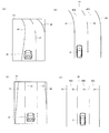
図3(A)、図3(C)及び図3(E)は、本実施形態の車両用表示装置1の表示部5であるディスプレイ5Aへの表示例を説明する図である。図3(B)、図3(D)及び図3(F)は、図3(A)、図3(C)及び図3(E)にそれぞれ対応する実際の車両2の道路20の走行状況を説明する図である。尚、図3(A)〜図3(F)の説明では、適宜、図1〜図2の説明を参照するものとする。
FIGS. 3A, 3 </ b> C, and 3 </ b> E are diagrams for explaining display examples on the
先ず、図3(A)及び図3(B)は、車両2が道路20の左側の車線20Aを走行している状況を示している。図3(B)に示すように、車両2が車線20Aを直進して走行しているが、車両2が車線20Aの中心よりも区画線22側へ片寄って走行している。そして、車両2の周辺環境認識部7が、道路20の区画線22〜24を認識し、その取得したデータから車両2の走行する車線20Aの車線幅データと、車両2の自車位置から車両2の左右の区画線22、23までの距離データを生成する。その後、周辺環境認識部7は、上記各種データを用いて算出し、車両2の左右の区画線22、23に対する相対位置データ及び表示用の相対位置データを生成し、記憶部4へ記憶させる。
First, FIG. 3A and FIG. 3B show a situation in which the
具体的には、車両2の周辺環境認識部7では、例えば、前方カメラ9であるステレオカメラの中央真下の道路面を原点として、車両2の横幅方向をx軸、車両2の高さ方向をy軸、車両の長さ方向をz軸とする。そして、ステレオカメラにて車両2の進行方向を撮像した1組のステレオ画像に対し、対応する位置ずれ量から三角測量の原理によって距離データを生成する。周辺環境認識部7は、その距離データとして、例えば、車両2が走行する車線20Aの車線幅データ、車両2の自車位置から左右の区画線22、23までの距離データ等を取得する。そして、周辺環境認識部7は、上記車線20Aの車線幅データと車両2から左右の区画線22、23までの距離データとの比率を算出し、車両2の左右の区画線22、23に対する相対位置データを生成する。その後、上記相対位置データから表示部5への表示用の相対位置データを演算して生成する。
Specifically, in the surrounding
図3(A)に示すように、表示部5のディスプレイ5Aは、例えば、縦長の長方形の表示エリアを有し、ディスプレイ5Aには、自車両アイコン31及び3本のラインアイコン32、33、34が表示されている。そして、自車両アイコン31は車両2(図3(B)参照)に対応し、ラインアイコン32は区画線22(図3(B)参照)に対応し、ラインアイコン33は区画線23(図3(B)参照)に対応し、ラインアイコン34は区画線24(図3(B)参照)に対応している。
As shown in FIG. 3A, the
本実施の形態では、自車両アイコン31は、ディスプレイ5Aの中央の下端部近傍に表示され、車両2が車線20Aの車線幅方向に少し蛇行した場合や車線変更等行った場合でも、常時、この位置に固定して表示される。一方、ラインアイコン32〜34は、ディスプレイ5A内にて紙面の左右方向、つまり、車線幅方向に移動しながら表示される。そして、図3(B)を用いて上述したように、車両2は車線20Aを走行しているが、区画線22側へ片寄って走行している。そのため、図3(A)では、自車両アイコン31に対してラインアイコン32〜34はディスプレイ5Aの紙面右側へ移動し、ラインアイコン32が自車両アイコン31に対して最も近い位置に表示されている。
In the present embodiment, the
次に、図3(C)及び図3(D)は、車両2が道路20の左側の車線20Aから右側の車線20Bへ車線変更を行うため、道路20を右斜め前方へ走行している。図3(D)に示すように、車両2は、車線変更中であり、区画線23上を走行している。この場合においても、上述したように、車両2の周辺環境認識部7が、道路20の区画線22〜24を認識し、車両2の区画線22、23、24に対する相対位置データ及び表示用の相対位置データを生成し、記憶部4へ記憶させる。
Next, in FIGS. 3C and 3D, the
図3(C)に示すように、実際には車両2は紙面左側から右側へと移動しているが、ディスプレイ5Aの表示では、自車両アイコン31は画面の中央の下端部近傍に固定表示され、ラインアイコン32〜34は、自車両アイコン31に対してディスプレイ5Aの紙面左側へ移動し、自車両アイコン31がラインアイコン33上に表示されている。
As shown in FIG. 3 (C), the
次に、図3(E)及び図3(F)は、車両2が道路20の右側の車線20Bへ車線変更を終え、車両2が車線20Bを直進して走行している。図3(F)に示すように、車両2は、車線変更した後、車線20Bの区画線23側へ片寄って走行している。この場合においても、上述したように、車両2の周辺環境認識部7が、道路20の区画線22〜24を認識し、車両2の区画線23、24に対する相対位置データ及び表示用の相対位置データを生成し、記憶部4へ記憶させる。
Next, in FIGS. 3E and 3F, the
図3(E)に示すように、実際には車両2は紙面左側から右側へと移動しているが、ディスプレイ5Aの表示では、自車両アイコン31は画面の中央の下端部近傍に固定表示され、ラインアイコン32〜34は、自車両アイコン31に対してディスプレイ5Aの紙面左側へ移動し、ラインアイコン33が自車両アイコン31に対して最も近い位置に表示されている。
As shown in FIG. 3 (E), the
尚、図3(A)及び図3(E)において、それぞれ車両2が区画線22、23を逸脱する恐れがある場合には、ラインアイコン32、33が点滅して表示される等、ドライバに対して強調して表示され、併せて、報知部6であるスピーカーから警告音が発せられる。また、図3(C)において、車両2がウインカーを点滅させながら車線変更する場合には、ラインアイコン33が強調して表示されることはなく、また、スピーカーから警告音が発せられることもない。
In FIGS. 3A and 3E, when there is a possibility that the
上述したように、ディスプレイ5Aには、自車両アイコン31が固定表示され、ラインアイコン32〜34が紙面左右方向に移動表示される。この表示方法により、自車両アイコン31が、ディスプレイ5A内にて紙面左右方向に揺れながら表示されることが防止される。そして、自車両アイコン31がドライバに対してちらついて表示され、見難くなることが防止され、ドライバは直観的に走行車線内の自車両の位置を把握し易くなる。
As described above, the
更には、ラインアイコン32〜34間の幅、つまり、表示上の車線幅W1、W2(図3(C)参照)は、実際の車線20A、20B(図3(D)参照)の幅が変化した場合でも、同じ幅のまま表示される。この表示方法により、ラインアイコン32〜34は、自車両アイコン31との離間距離に応じて紙面左右方向に移動するのみとなり、実際の車線20A、20Bの幅に対応して紙面左右方向に移動することはない。つまり、ラインアイコン32〜34の移動量は、必要最小限に設定されることで、ラインアイコン32〜34がドライバに対してちらついて表示され、見難くなることが防止され、ドライバは直観的に走行車線内の自車両の位置を把握し易くなる。
Furthermore, the width between the
また、ドライバが実際に車両2を運転する際、多くのドライバの視線の感覚は、車両2を走行車線に沿って運転している感覚であり、車両2が走行車線内を左右に小さく蛇行しながら走行している感覚ではないものと推測される。そのため、ディスプレイ5Aには自車両アイコン31を固定表示し、ラインアイコン32〜34の表示を自車両アイコン31に対して移動させることで、実際のドライバの視線と合った表示となり、ドライバは直観的に走行車線内の車両2の位置を的確に把握し易くなる。
In addition, when the driver actually drives the
尚、図3(A)、図3(C)及び図3(E)に示すように、ラインアイコン32〜34は、紙面上端側、つまり、自車両アイコン31よりも遠方側に行く程、ラインアイコン32〜34の離間距離が狭まるように表示されている。この表示方法も、実際のドライバの視線の遠近感と合った表示となり、ドライバは直観的に走行車線の先の情報を把握し易くなる。
As shown in FIGS. 3A, 3C, and 3E, the
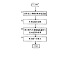
図4は、本実施形態の車両用表示装置1の表示部5に表示されるまでの制御動作の一例を示すフローチャートである。尚、図4のフローチャートでは、図3(A)及び図3(B)に示す走行状態を用いて説明するものとする。
FIG. 4 is a flowchart illustrating an example of the control operation until the display is performed on the
図4に示す如く、ステップS1において、車両制御部3が、記憶部4及び周辺環境認識部7を制御し、車両2が走行している車線20Aの車線幅を認識する。上述したように、周辺環境認識部7の前方カメラ9であるステレオカメラを介して車両2の進行方向の画像を取得する。そして、撮像した1組のステレオ画像に対し、前方カメラ9とユニット化された画像処理エンジンにより対応する位置ずれ量から三角測量の原理によって、車線20Aの車線幅データを取得し、記憶部4に記憶させる。尚、周辺環境認識部7が隣の車線20Bを認識している場合には、車線20Bの車線幅データも取得し、記憶部4に記憶させる。
As shown in FIG. 4, in step S1, the
次に、ステップS2において、車両制御部3が、記憶部4及び周辺環境認識部7を制御し、上記ステップS1の三角測量により生成された距離データに基づいて、車両2が車線20A内の車線幅方向に対しどの位置を走行しているかの自車位置を認識する。上記三角測量により車線幅データの他に、上記ステレオカメラの中央真下の道路面を原点として車両2から左右の区画線22、23までの距離データも取得し、記憶部4に記憶させる。そして、上記画像処理エンジンにより、車線幅データと車両2から左右の区画線22、23までの距離データとの比率を算出し、車線20Aに対する自車両の相対位置データを生成し、記憶部4に記憶させる。
Next, in step S2, the
次に、ステップS3において、車両制御部3が、記憶部4及び周辺環境認識部7を制御し、表示部5内の車線幅W1、W2(図3(C)参照)を基準として実際の車線20Aに対する上記相対位置データから表示用の相対位置データを演算する。上述したように、表示部5のディスプレイ5Aに表示されるラインアイコン32〜34間の車線幅W1、W2は、実際の車線20A、20Bの幅が変化した場合でも、同じ幅のまま表示される。そのため、実際の車線20Aに対する上記相対位置データから表示部5への表示用の相対位置データを演算して生成し、記憶部4に記憶させる。
Next, in step S3, the
次に、ステップS4において、車両制御部3が、記憶部4及び表示部5を制御し、表示部5のディスプレイ5Aには、自車両アイコン31及びラインアイコン32〜34が表示される。尚、ラインアイコン32〜34は、周辺環境認識部7により認識された場合にはディスプレイ5Aに表示され、周辺環境認識部7により認識されない場合にはディスプレイ5Aには表示されない。
Next, in step S <b> 4, the
尚、周辺環境認識部7として前方カメラ9が用いられる場合には、道路20の区画線22〜24が薄い状況や夜間の走行中等、前方カメラ9にて区画線22〜24を認識出来ない場合もある。そして、そのような状況では、実際に車両2を運転しているドライバも区画線22〜24を視認出来ない場合も多く、ディスプレイ5Aには、前方カメラ9にて認識出来ない区画線22〜24は表示されない。この場合、ドライバの視線とディスプレイ5Aへの表示が一致することで、ドライバは直観的に自車周辺の走行環境を把握し易くなる。
In addition, when the
また、本実施の形態では、周辺環境認識部7として前方カメラ9が用いられる場合について説明したが、この場合に限定するものではない。上述したように、周辺環境認識部7として、GPS衛星からの車両2の自車位置と記憶部4に記憶されている詳細地図データベースとを組み合わせて、表示部5への表示用の相対位置データを演算して生成し、表示部5に自車両アイコン31及びラインアイコン32〜34が表示される場合でも良い。この場合には、実際にドライバが視認出来ていない区画線22〜24が、表示部5にラインアイコン32〜34として表示されるが、例えば、実際にドライバが雪により区画線22〜24が見えない場合等、そのラインアイコン32〜34を目安に走行することで、車線20A、20Bからの車両2が逸脱することを防止することも可能である。
Moreover, although the case where the
次に、図5(A)及び図5(B)を用いて上述した本発明の実施形態の車両用表示装置1の変形例を説明する。尚、図1〜図4を用いて説明した車両用表示装置1と同一構成要素には原則として同一の符番を用い、繰り返しの説明は省略し、上述した実施形態と異なる構成要素を説明する。
Next, a modified example of the
図5(A)及び図5(C)は、本実施形態の車両用表示装置1の表示部5であるディスプレイ5Aへの表示例を説明する図である。図5(B)及び図5(D)は、図5(A)及び図5(C)にそれぞれ対応する実際の車両2の道路40、50の走行状況を説明する図である。
FIG. 5A and FIG. 5C are diagrams illustrating a display example on the
先ず、図5(A)及び図5(B)は、車両2が片側2車線40A、40Bの道路40を走行し、その道路の先がカーブしている状況を示している。図5(B)に示すように、車両2が車線40Aを直進して走行しているが、車両2が車線40Aの中心よりも区画線41側へ片寄って走行している。そして、道路40は、車両2の進行方向の先側にて左側に緩やかにカーブしている。尚、上述した実施形態と同様に、周辺環境認識部7は、車両2の左右の区画線41、42に対する相対位置データ及びディスプレイ5Aのラインアイコン44、45に対する相対位置データを生成する。
First, FIGS. 5A and 5B show a situation in which the
図5(A)に示すように、ディスプレイ5Aには、自車両アイコン31及び3本のラインアイコン44、45、46が表示されている。そして、自車両アイコン31は車両2(図5(B)参照)に対応し、ラインアイコン44は区画線41(図5(B)参照)に対応し、ラインアイコン45は区画線42(図5(B)参照)に対応し、ラインアイコン46は区画線43(図5(B)参照)に対応している。
As shown in FIG. 5 (A), the
本実施の形態においても、自車両アイコン31は、ディスプレイ5Aの中央の下端部近傍に固定表示され、ラインアイコン44〜46は、ディスプレイ5A内にて紙面の左右方向、つまり、車線幅方向に移動しながら表示される。そして、図示したように、周辺環境認識部7にて、道路40の進行方向の先側がカーブしていると認識した場合には、ディスプレイ5Aに表示されるラインアイコン44〜46も上端側がカーブして表示される。この表示方法により、ドライバは直観的に走行車線の状況を把握し易くなる。
Also in the present embodiment, the
次に、図5(C)及び図5(D)は、車両2が片側3車線50A、50B、50Cの道路50を走行している状況を示している。図5(D)に示すように、車両2が中央の車線50Bを直進して走行しているが、車両2が車線50Bの中心よりも区画線52側へ片寄って走行している。尚、上述した実施形態と同様に、周辺環境認識部7は、車両2の左右の区画線52、53に対する相対位置データ及びディスプレイ5Aのラインアイコン52、53に対する相対位置データを生成する。
Next, FIG. 5 (C) and FIG. 5 (D) show a situation in which the
図5(C)に示すように、ディスプレイ5Aには、自車両アイコン31及び4本のラインアイコン55、56、57、58が表示されている。そして、自車両アイコン31は車両2(図5(D)参照)に対応し、ラインアイコン55は区画線51(図5(D)参照)に対応し、ラインアイコン56は区画線52(図5(D)参照)に対応し、ラインアイコン57は区画線53(図5(D)参照)に対応し、ラインアイコン58は区画線54(図5(D)参照)に対応している。
As shown in FIG. 5C, the
本実施の形態においても、自車両アイコン31は、ディスプレイ5Aの中央の下端部近傍に固定表示され、ラインアイコン55〜58は、ディスプレイ5A内にて紙面の左右方向、つまり、車線幅方向に移動しながら表示される。図示したように、ラインアイコン58はその一部のみが表示されているが、周辺環境認識部7にて区画線54を認識している場合には、車両2が車線50C側へと移動することで、適宜、ラインアイコン58はディスプレイ5A内にて全て表示されていく。つまり、自車両アイコン31を固定表示とし、ラインアイコン55〜58を移動表示とすることで、ディスプレイ5A内に必ず全てのラインアイコン55〜58を表示する必要はない。例えば、2車線分が表示可能な表示スペースにて、車両2の動きに合わせて、順次、3車線以上の車線情報を表示することができる。この表示方法により、自車両アイコン31の表示やラインアイコン55〜58の表示を小さくすることはなく、ドライバに対して見易い表示が実現され、ドライバは直観的に走行環境を把握し易くなる。
Also in the present embodiment, the
尚、本実施形態では、片側2車線及び片側3車線の道路を車両2が走行する場合について説明したが、この場合に限定するものではない。例えば、片側1車線の道路や片側4車線以上の道路を車両2が走行する場合でも、表示部5に車両2の自車両アイコンを固定表示し、道路の区画線のラインアイコンを左右方向に移動表示することで同様な効果を得ることができる。その他、本発明の要旨を逸脱しない範囲にて種々の変更が可能である。
In addition, although this embodiment demonstrated the case where the
1 車両用表示装置
2 車両
3 車両制御部
4 記憶部
5 表示部
5A、5B ディスプレイ
6 報知部
7 周辺環境認識部
8 車速センサ
9 前方カメラ
10 後方カメラ
11 前方レーダ
12 後方レーダ
13 通信部
14 ステアリング
20 道路
20A、20B 車線
22、23、24 区画線
31 自車両アイコン
32、33、34 ラインアイコン
DESCRIPTION OF
Claims (6)
前記周辺環境認識手段により認識した結果からドライバへの報知が必要な情報を前記自車両の表示エリアに表示する表示手段と、を有し、
前記表示手段は、前記表示エリアの横方向のほぼ中央に自車両アイコンを表示し、前記周辺環境認識手段により前記自車両が走行する自車走行車線の区画線が認識されたときには前記自車両アイコンの左右側方にラインアイコンを表示し、
前記ラインアイコンは、前記自車両アイコンの遠方ほど前記ラインアイコン間の距離が狭まるように表示され、
前記自車両アイコンは固定して表示され、前記ラインアイコンは前記表示エリアの横方向に移動して表示され、
前記ラインアイコンは、前記自車両の前記自車走行車線の車線幅方向における移動方向と反対方向に移動して表示されることを特徴とする車両用表示装置。 A surrounding environment recognition means for recognizing the surrounding environment of the vehicle;
Display means for displaying, in the display area of the host vehicle, information necessary to notify the driver from the result recognized by the surrounding environment recognition means,
The display means displays a host vehicle icon at a substantially central position in the lateral direction of the display area, and the host vehicle icon is displayed when a lane marking of the host vehicle traveling lane in which the host vehicle travels is recognized by the surrounding environment recognition unit. Display line icons on the left and right sides of
The line icon is displayed so that the distance between the line icons becomes narrower as the vehicle icon is further away.
The own vehicle icon is fixedly displayed, and the line icon is displayed by moving in the horizontal direction of the display area,
The vehicle display device, wherein the line icon is displayed by moving in a direction opposite to a moving direction in a lane width direction of the own vehicle traveling lane of the own vehicle.
Priority Applications (4)
| Application Number | Priority Date | Filing Date | Title |
|---|---|---|---|
| JP2016233776A JP2018092290A (en) | 2016-12-01 | 2016-12-01 | Vehicle display device |
| US15/808,426 US10223920B2 (en) | 2016-12-01 | 2017-11-09 | Display device for vehicle |
| CN201711112624.2A CN108128244B (en) | 2016-12-01 | 2017-11-13 | Display device for vehicle |
| DE102017128531.8A DE102017128531A1 (en) | 2016-12-01 | 2017-12-01 | Display device for a vehicle |
Applications Claiming Priority (1)
| Application Number | Priority Date | Filing Date | Title |
|---|---|---|---|
| JP2016233776A JP2018092290A (en) | 2016-12-01 | 2016-12-01 | Vehicle display device |
Publications (1)
| Publication Number | Publication Date |
|---|---|
| JP2018092290A true JP2018092290A (en) | 2018-06-14 |
Family
ID=62164173
Family Applications (1)
| Application Number | Title | Priority Date | Filing Date |
|---|---|---|---|
| JP2016233776A Pending JP2018092290A (en) | 2016-12-01 | 2016-12-01 | Vehicle display device |
Country Status (4)
| Country | Link |
|---|---|
| US (1) | US10223920B2 (en) |
| JP (1) | JP2018092290A (en) |
| CN (1) | CN108128244B (en) |
| DE (1) | DE102017128531A1 (en) |
Families Citing this family (4)
| Publication number | Priority date | Publication date | Assignee | Title |
|---|---|---|---|---|
| JP7011559B2 (en) * | 2018-09-11 | 2022-01-26 | 本田技研工業株式会社 | Display devices, display control methods, and programs |
| JP6991948B2 (en) * | 2018-09-11 | 2022-01-13 | 本田技研工業株式会社 | Display system, display control method, and program |
| JP7440237B2 (en) | 2019-10-16 | 2024-02-28 | トヨタ自動車株式会社 | display device |
| JP7211397B2 (en) * | 2020-05-15 | 2023-01-24 | トヨタ自動車株式会社 | Other vehicle display system |
Citations (4)
| Publication number | Priority date | Publication date | Assignee | Title |
|---|---|---|---|---|
| JPH0991596A (en) * | 1995-09-25 | 1997-04-04 | Mitsubishi Motors Corp | Display device for vehicle circumference information |
| JPH11126300A (en) * | 1997-10-21 | 1999-05-11 | Mazda Motor Corp | Lane deviation warning device for vehicle |
| JPH11264868A (en) * | 1998-03-17 | 1999-09-28 | Hitachi Ltd | Display device for vehicle |
| JP2014203122A (en) * | 2013-04-01 | 2014-10-27 | 怡利電子工業股▲ふん▼有限公司 | Method for displaying driving safety distance |
Family Cites Families (14)
| Publication number | Priority date | Publication date | Assignee | Title |
|---|---|---|---|---|
| JP3196473B2 (en) | 1993-12-29 | 2001-08-06 | 日産自動車株式会社 | Inter-vehicle distance alarm |
| JP4576684B2 (en) | 2000-09-05 | 2010-11-10 | マツダ株式会社 | Lane change support system |
| DE102004036566A1 (en) * | 2004-07-28 | 2006-03-23 | Robert Bosch Gmbh | Night vision device |
| JP4575275B2 (en) | 2005-11-02 | 2010-11-04 | 三菱ふそうトラック・バス株式会社 | Vehicle display device |
| US20070213886A1 (en) * | 2006-03-10 | 2007-09-13 | Yilu Zhang | Method and system for driver handling skill recognition through driver's steering behavior |
| JP2007253730A (en) * | 2006-03-22 | 2007-10-04 | Denso Corp | Vehicular security device and vehicular security system |
| US8154418B2 (en) | 2008-03-31 | 2012-04-10 | Magna Mirrors Of America, Inc. | Interior rearview mirror system |
| US8305444B2 (en) * | 2008-11-14 | 2012-11-06 | Toyota Motor Engineering & Manufacturing North America, Inc. | Integrated visual display system |
| JP5316713B2 (en) * | 2011-06-08 | 2013-10-16 | トヨタ自動車株式会社 | Lane departure prevention support apparatus, lane departure prevention method, and storage medium |
| EP3150966B1 (en) * | 2012-07-27 | 2019-06-26 | Harman Becker Automotive Systems GmbH | Navigation system and method for navigation |
| JP5783155B2 (en) | 2012-10-05 | 2015-09-24 | 株式会社デンソー | Display device |
| JP2014145999A (en) | 2013-01-30 | 2014-08-14 | Denso Corp | Control system |
| US9522676B2 (en) * | 2014-04-30 | 2016-12-20 | Denso International America, Inc. | Situation awareness assistant for vehicle control |
| JP6466899B2 (en) * | 2016-12-01 | 2019-02-06 | 株式会社Subaru | Vehicle display device |
-
2016
- 2016-12-01 JP JP2016233776A patent/JP2018092290A/en active Pending
-
2017
- 2017-11-09 US US15/808,426 patent/US10223920B2/en active Active
- 2017-11-13 CN CN201711112624.2A patent/CN108128244B/en active Active
- 2017-12-01 DE DE102017128531.8A patent/DE102017128531A1/en not_active Withdrawn
Patent Citations (4)
| Publication number | Priority date | Publication date | Assignee | Title |
|---|---|---|---|---|
| JPH0991596A (en) * | 1995-09-25 | 1997-04-04 | Mitsubishi Motors Corp | Display device for vehicle circumference information |
| JPH11126300A (en) * | 1997-10-21 | 1999-05-11 | Mazda Motor Corp | Lane deviation warning device for vehicle |
| JPH11264868A (en) * | 1998-03-17 | 1999-09-28 | Hitachi Ltd | Display device for vehicle |
| JP2014203122A (en) * | 2013-04-01 | 2014-10-27 | 怡利電子工業股▲ふん▼有限公司 | Method for displaying driving safety distance |
Also Published As
| Publication number | Publication date |
|---|---|
| US20180158339A1 (en) | 2018-06-07 |
| CN108128244B (en) | 2022-12-13 |
| US10223920B2 (en) | 2019-03-05 |
| DE102017128531A1 (en) | 2018-06-07 |
| CN108128244A (en) | 2018-06-08 |
Similar Documents
| Publication | Publication Date | Title |
|---|---|---|
| JP6466899B2 (en) | Vehicle display device | |
| US10254539B2 (en) | On-vehicle device, method of controlling on-vehicle device, and computer-readable storage medium | |
| CN111052733B (en) | Surrounding vehicle display method and surrounding vehicle display device | |
| US10293690B2 (en) | Vehicle information projecting system and vehicle information projecting method | |
| WO2015146619A1 (en) | Vehicle warning device | |
| EP3017989A1 (en) | Drive assist device | |
| WO2017022047A1 (en) | Display control device, display device, and display control method | |
| JP6744064B2 (en) | Automotive image display system | |
| WO2015163205A1 (en) | Vehicle display system | |
| JP6443716B2 (en) | Image display device, image display method, and image display control program | |
| US20200249044A1 (en) | Superimposed-image display device and computer program | |
| JP7006235B2 (en) | Display control device, display control method and vehicle | |
| CN108128244B (en) | Display device for vehicle | |
| JP7011559B2 (en) | Display devices, display control methods, and programs | |
| EP3505381A1 (en) | Display system | |
| TW201843069A (en) | Dynamic information system and method for operating a dynamic information system | |
| CN111034186A (en) | Surrounding vehicle display method and surrounding vehicle display device | |
| CN110626265B (en) | Periphery monitoring device | |
| JP6186905B2 (en) | In-vehicle display device and program | |
| US20210049985A1 (en) | Image control apparatus, display apparatus, mobile body, image data generation method, and recording medium | |
| US11214197B2 (en) | Vehicle surrounding area monitoring device, vehicle surrounding area monitoring method, vehicle, and storage medium storing program for the vehicle surrounding area monitoring device | |
| CN113306392A (en) | Display method, in-vehicle terminal, vehicle, and computer-readable storage medium | |
| JP2018019155A (en) | Display controller for vehicle, display system for vehicle, display control method for vehicle and program | |
| WO2022270207A1 (en) | Vehicular display control device and vehicular display control program | |
| JP7359205B2 (en) | Display control method and display control device |
Legal Events
| Date | Code | Title | Description |
|---|---|---|---|
| A977 | Report on retrieval |
Free format text: JAPANESE INTERMEDIATE CODE: A971007 Effective date: 20180910 |
|
| A131 | Notification of reasons for refusal |
Free format text: JAPANESE INTERMEDIATE CODE: A131 Effective date: 20180925 |
|
| A521 | Request for written amendment filed |
Free format text: JAPANESE INTERMEDIATE CODE: A523 Effective date: 20181119 |
|
| A02 | Decision of refusal |
Free format text: JAPANESE INTERMEDIATE CODE: A02 Effective date: 20181218 |