JP2018019155A - Display controller for vehicle, display system for vehicle, display control method for vehicle and program - Google Patents

Display controller for vehicle, display system for vehicle, display control method for vehicle and program Download PDF

Info

Publication number
JP2018019155A
JP2018019155A JP2016146001A JP2016146001A JP2018019155A JP 2018019155 A JP2018019155 A JP 2018019155A JP 2016146001 A JP2016146001 A JP 2016146001A JP 2016146001 A JP2016146001 A JP 2016146001A JP 2018019155 A JP2018019155 A JP 2018019155A
Authority
JP
Japan
Prior art keywords
video data
vehicle
rear video
unit
display control
Prior art date
Legal status (The legal status is an assumption and is not a legal conclusion. Google has not performed a legal analysis and makes no representation as to the accuracy of the status listed.)
Pending
Application number
JP2016146001A
Other languages
Japanese (ja)
Other versions
JP2018019155A5 (en
Inventor
昇 勝俣
Noboru Katsumata
昇 勝俣
泉 佐伯
Izumi Saeki
泉 佐伯
英明 岡村
Hideaki Okamura
英明 岡村
Current Assignee (The listed assignees may be inaccurate. Google has not performed a legal analysis and makes no representation or warranty as to the accuracy of the list.)
JVCKenwood Corp
Original Assignee
JVCKenwood Corp
Priority date (The priority date is an assumption and is not a legal conclusion. Google has not performed a legal analysis and makes no representation as to the accuracy of the date listed.)
Filing date
Publication date
Application filed by JVCKenwood Corp filed Critical JVCKenwood Corp
Priority to JP2016146001A priority Critical patent/JP2018019155A/en
Priority to PCT/JP2017/015014 priority patent/WO2018020751A1/en
Publication of JP2018019155A publication Critical patent/JP2018019155A/en
Priority to US16/170,164 priority patent/US10730434B2/en
Publication of JP2018019155A5 publication Critical patent/JP2018019155A5/ja
Pending legal-status Critical Current

Links

Images

Landscapes

  • Image Processing (AREA)
  • Closed-Circuit Television Systems (AREA)
  • Image Analysis (AREA)

Abstract

PROBLEM TO BE SOLVED: To allow for appropriate confirmation around a vehicle.SOLUTION: A display controller for vehicle includes a rear video data acquisition unit 42 for acquiring first video data from a rear camera 110 for photographing the rear of a vehicle, a side rear video data acquisition unit 41 for acquiring side rear video data from a right rear camera 120 and a left rear camera 130 for photographing the right and left rear of the vehicle, a travel state information acquisition unit 60 for acquiring information indicating the travel state of the vehicle, a video synthesis unit 52 for combining the right rear video data and left rear video data on upper right and left, according to the travel state acquired by the travel state information acquisition unit 60, and a display control unit 70 controlling a rear view monitor 140 for displaying the rear video of the vehicle to display the rear video data combined by the video synthesis unit 52.SELECTED DRAWING: Figure 3

Description

本発明は、車両用表示制御装置、車両用表示システム、車両用表示制御方法およびプログラムに関する。   The present invention relates to a vehicle display control device, a vehicle display system, a vehicle display control method, and a program.

車両の後方周辺領域を撮影する後方カメラからの映像を表示する、いわゆる電子ミラーに関する技術が知られている。電子ミラーは、従来の光学式ルームミラーと異なり、2次元の映像の実像であるため、被撮影物の距離感を認識しにくかったり、運転者が違和感を覚えたりすることがある。そこで、自車両とカメラが撮影した物体との距離感の誤認識を抑制した車載用表示装置が知られている(例えば、特許文献1参照)。また、視野調整操作の煩雑さを解消し、違和感のない左右後方映像を表示する車両用後方視認システムが知られている(例えば、特許文献2参照)。   A technique related to a so-called electronic mirror that displays an image from a rear camera that captures a rear peripheral region of a vehicle is known. Unlike a conventional optical room mirror, the electronic mirror is a real image of a two-dimensional image, so it may be difficult to recognize the sense of distance of the subject and the driver may feel uncomfortable. Thus, an in-vehicle display device that suppresses misrecognition of a sense of distance between the host vehicle and an object photographed by a camera is known (for example, see Patent Document 1). There is also known a vehicular rearward viewing system that eliminates the complexity of the visual field adjustment operation and displays right and left rear images without a sense of incongruity (see, for example, Patent Document 2).

特開2016−063352号公報JP 2006-066332 A 特開2011−217318号公報JP 2011-217318 A

運転者は、運転中に車両周辺を確認するため、リヤビューモニタと、左右サイドビューモニタとを視認する。リヤビューモニタと、左右サイドビューモニタとが離れて設置されているので、車両周辺の確認には視線移動をともなう。また、運転者が運転中に短い時間で認識可能な情報量は限られている。このため、リヤビューモニタや左右サイドビューモニタには、運転者が情報を必要とするタイミングで、適切な情報量の映像を表示することが望ましい。このように、適切な車両周辺の確認を可能にする技術が望まれている。   The driver visually recognizes the rear view monitor and the left and right side view monitors in order to check the periphery of the vehicle during driving. Since the rear view monitor and the left and right side view monitors are set apart from each other, the line of sight is moved to check the surroundings of the vehicle. In addition, the amount of information that the driver can recognize in a short time during driving is limited. Therefore, it is desirable to display an image with an appropriate amount of information on the rear view monitor and the left and right side view monitors at a timing when the driver needs information. Thus, a technique that enables confirmation of an appropriate vehicle periphery is desired.

本発明は、上記に鑑みてなされたものであって、適切な車両周辺の確認を可能とすることを目的とする。   The present invention has been made in view of the above, and an object thereof is to enable appropriate confirmation of the periphery of a vehicle.

上述した課題を解決し、目的を達成するために、本発明に係る車両用表示制御装置は、車両の後方を向くように配置され、前記車両の後方を撮影する後方カメラからの後方映像データを取得する後方映像データ取得部と、前記車両の左右側方に前記車両の後方を向くように配置され、前記車両の左右側後方を撮影する側後方カメラからの側後方映像データを取得する側後方映像データ取得部と、前記車両の走行状況を示す情報を取得する走行状況情報取得部と、前記走行状況情報取得部が取得した走行状況に応じて、前記後方映像データの左右上方に前記側後方映像データを合成する映像合成部と、前記映像合成部が合成した後方映像データを、前記車両の後方映像を表示する表示装置に表示させる表示制御部と、を備えることを特徴とする。   In order to solve the above-described problems and achieve the object, a vehicle display control device according to the present invention is arranged so as to face the rear of the vehicle, and rear image data from a rear camera that captures the rear of the vehicle. A rear video data acquisition unit for acquiring, and a rear side for acquiring side rear video data from a side rear camera that is arranged to face the rear of the vehicle on the left and right sides of the vehicle and captures the left and right sides of the vehicle A video data acquisition unit, a driving status information acquisition unit that acquires information indicating the driving status of the vehicle, and the rear side of the rear video data according to the driving status acquired by the driving status information acquisition unit A video synthesis unit that synthesizes video data, and a display control unit that displays the rear video data synthesized by the video synthesis unit on a display device that displays the rear video of the vehicle.

本発明に係る車両用表示システムは、上記の車両用表示制御装置と、少なくとも前記表示装置、前記後方カメラ、前記側後方カメラのうち少なくともいずれかと、を備える。   The vehicle display system according to the present invention includes the vehicle display control device and at least one of the display device, the rear camera, and the side rear camera.

本発明に係る車両用表示制御方法は、車両の後方を向くように配置され、前記車両の後方を撮影する後方カメラからの後方映像データを取得する後方映像データ取得ステップと、前記車両の左右側方に前記車両の後方を向くように配置され、前記車両の左右側後方を撮影する側後方カメラからの側後方映像データを取得する側後方映像データ取得ステップと、前記車両の走行状況を示す情報を取得する走行状況情報取得ステップと、前記走行状況情報取得ステップが取得した走行状況に応じて、前記後方映像データの左右上方に前記側後方映像データを合成する映像合成ステップと、前記映像合成ステップが合成した後方映像データを、前記車両の後方映像を表示する表示装置に表示させる表示制御ステップと、を含む。   The vehicle display control method according to the present invention includes a rear video data acquisition step that is arranged to face the rear of the vehicle and acquires rear video data from a rear camera that captures the rear of the vehicle, and the left and right sides of the vehicle A side rear image data acquisition step for acquiring side rear image data from a side rear camera that captures the left and right rear sides of the vehicle, and information indicating a traveling state of the vehicle. A driving situation information acquisition step for acquiring the image, a video synthesis step for synthesizing the side rear video data on the left and right upper sides of the rear video data according to the driving situation acquired by the driving status information acquisition step, and the video synthesis step And a display control step of displaying the rear video data synthesized by the information on a display device that displays the rear video of the vehicle.

本発明に係るプログラムは、車両の後方を向くように配置され、前記車両の後方を撮影する後方カメラからの後方映像データを取得する後方映像データ取得ステップと、前記車両の左右側方に前記車両の後方を向くように配置され、前記車両の左右側後方を撮影する側後方カメラからの側後方映像データを取得する側後方映像データ取得ステップと、前記車両の走行状況を示す情報を取得する走行状況情報取得ステップと、前記走行状況情報取得ステップが取得した走行状況に応じて、前記後方映像データの左右上方に前記側後方映像データを合成する映像合成ステップと、前記映像合成ステップが合成した後方映像データを、前記車両の後方映像を表示する表示装置に表示させる表示制御ステップと、を車両用表示制御装置として動作するコンピュータに実行させる。   The program according to the present invention is arranged so as to face the rear of the vehicle, acquires a rear video data from a rear camera that captures the rear of the vehicle, and the vehicle on the left and right sides of the vehicle. A side rear image data acquisition step for acquiring side rear image data from a side rear camera that images the left and right rear sides of the vehicle, and traveling for acquiring information indicating the traveling state of the vehicle A situation information acquisition step, a video synthesis step of synthesizing the side rear video data on the left and right upper sides of the rear video data according to the driving situation acquired by the driving status information acquisition step, and a rear synthesized by the video synthesis step A display control step of displaying video data on a display device that displays a rear image of the vehicle, and operates as a vehicle display control device To be executed by a computer.

本発明によれば、適切な車両周辺の確認を可能にすることができるという効果を奏する。   According to the present invention, there is an effect that it is possible to make it possible to appropriately check the vicinity of the vehicle.

図1は、第一実施形態に係る車両用表示システムの構成例を示す概略図である。FIG. 1 is a schematic diagram illustrating a configuration example of a vehicle display system according to the first embodiment. 図2は、第一実施形態に係る車両用表示システムの構成例を示す概略図である。FIG. 2 is a schematic diagram illustrating a configuration example of the vehicle display system according to the first embodiment. 図3は、第一実施形態に係る車両用表示システムの構成例を示すブロック図である。FIG. 3 is a block diagram illustrating a configuration example of the vehicle display system according to the first embodiment. 図4は、第一実施形態に係る車両用表示システムの後方カメラで撮影された映像データの一例を示す図である。FIG. 4 is a diagram illustrating an example of video data captured by the rear camera of the vehicle display system according to the first embodiment. 図5は、第一実施形態に係る車両用表示システムのリヤビューモニタに表示される映像の一例を示す図である。FIG. 5 is a diagram illustrating an example of an image displayed on the rear view monitor of the vehicle display system according to the first embodiment. 図6は、第一実施形態に係る車両用表示システムの右サイドビューモニタに表示される映像の一例を示す図である。FIG. 6 is a diagram illustrating an example of an image displayed on the right side view monitor of the vehicle display system according to the first embodiment. 図7は、第一実施形態に係る車両用表示システムの左サイドビューモニタに表示される映像の一例を示す図である。FIG. 7 is a diagram illustrating an example of an image displayed on the left side view monitor of the vehicle display system according to the first embodiment. 図8は、第一実施形態に係る車両用表示システムのリヤビューモニタに表示される映像の他の例を示す図である。FIG. 8 is a diagram illustrating another example of an image displayed on the rear view monitor of the vehicle display system according to the first embodiment. 図9は、第一実施形態に係る車両用表示システムの車両用表示制御装置の制御部における処理の流れを示すフローチャートである。FIG. 9 is a flowchart showing the flow of processing in the control unit of the vehicle display control apparatus of the vehicle display system according to the first embodiment. 図10は、第一実施形態に係る車両用表示システムの後方カメラで撮影された映像データの他の例を示す図である。FIG. 10 is a diagram illustrating another example of the video data captured by the rear camera of the vehicle display system according to the first embodiment. 図11は、第一実施形態に係る車両用表示システムのリヤビューモニタに表示される映像の他の例を示す図である。FIG. 11 is a diagram illustrating another example of an image displayed on the rear view monitor of the vehicle display system according to the first embodiment. 図12は、第一実施形態に係る車両用表示システムの右サイドビューモニタに表示される映像の他の例を示す図である。FIG. 12 is a diagram illustrating another example of an image displayed on the right side view monitor of the vehicle display system according to the first embodiment. 図13は、第一実施形態に係る車両用表示システムの左サイドビューモニタに表示される映像の他の例を示す図である。FIG. 13 is a diagram illustrating another example of an image displayed on the left side view monitor of the vehicle display system according to the first embodiment. 図14は、第一実施形態に係る車両用表示システムのリヤビューモニタに表示される映像の他の例を示す図である。FIG. 14 is a diagram illustrating another example of an image displayed on the rear view monitor of the vehicle display system according to the first embodiment. 図15は、第二実施形態に係る車両用表示システムの車両用表示制御装置の制御部における処理の流れを示すフローチャートである。FIG. 15 is a flowchart showing a flow of processing in the control unit of the vehicle display control device of the vehicle display system according to the second embodiment. 図16は、第二実施形態に係る車両用表示システムの後方カメラで撮影された映像データの一例を示す図である。FIG. 16 is a diagram illustrating an example of video data captured by the rear camera of the vehicle display system according to the second embodiment. 図17は、第二実施形態に係る車両用表示システムのリヤビューモニタに表示される映像の一例を示す図である。FIG. 17 is a diagram illustrating an example of an image displayed on the rear view monitor of the vehicle display system according to the second embodiment. 図18は、第三実施形態に係る車両用表示システムの構成例を示すブロック図である。FIG. 18 is a block diagram illustrating a configuration example of the vehicle display system according to the third embodiment. 図19は、第三実施形態に係る車両用表示システムの車両用表示制御装置の制御部における処理の流れを示すフローチャートである。FIG. 19 is a flowchart illustrating a process flow in the control unit of the vehicle display control device of the vehicle display system according to the third embodiment. 図20は、第三実施形態に係る車両用表示システムの後方カメラで撮影された映像データの一例を示す図である。FIG. 20 is a diagram illustrating an example of video data captured by the rear camera of the vehicle display system according to the third embodiment. 図21は、第三実施形態に係る車両用表示システムのリヤビューモニタに表示される映像の一例を示す図である。FIG. 21 is a diagram illustrating an example of an image displayed on the rear view monitor of the vehicle display system according to the third embodiment. 図22は、第四実施形態に係る車両用表示システムの車両用表示制御装置の制御部における処理の流れを示すフローチャートである。FIG. 22 is a flowchart showing a flow of processing in the control unit of the vehicle display control apparatus of the vehicle display system according to the fourth embodiment. 図23は、第五実施形態に係る車両用表示システムの車両用表示制御装置の制御部における処理の流れを示すフローチャートである。FIG. 23 is a flowchart illustrating a process flow in the control unit of the vehicle display control device of the vehicle display system according to the fifth embodiment. 図24は、第五実施形態に係る車両用表示システムの後方カメラで撮影された映像データの一例を示す図である。FIG. 24 is a diagram illustrating an example of video data captured by the rear camera of the vehicle display system according to the fifth embodiment. 図25は、第五実施形態に係る車両用表示システムのリヤビューモニタに表示される映像の一例を示す図である。FIG. 25 is a diagram illustrating an example of an image displayed on the rear view monitor of the vehicle display system according to the fifth embodiment. 図26は、第六実施形態に係る車両用表示システムの車両用表示制御装置の制御部における処理の流れを示すフローチャートである。FIG. 26 is a flowchart showing the flow of processing in the control unit of the vehicle display control apparatus of the vehicle display system according to the sixth embodiment. 図27は、第六実施形態に係る車両用表示システムのリヤビューモニタに表示される映像の一例を示す図である。FIG. 27 is a diagram illustrating an example of an image displayed on the rear view monitor of the vehicle display system according to the sixth embodiment. 図28は、第六実施形態に係る車両用表示システムのリヤビューモニタに表示される映像の他の例を示す図である。FIG. 28 is a diagram illustrating another example of an image displayed on the rear view monitor of the vehicle display system according to the sixth embodiment. 図29は、第七実施形態に係る車両用表示システムの車両用表示制御装置の制御部における処理の流れを示すフローチャートである。FIG. 29 is a flowchart showing the flow of processing in the control unit of the vehicle display control apparatus of the vehicle display system according to the seventh embodiment.

以下に添付図面を参照して、本発明に係る車両用表示制御装置10、車両用表示システム1、車両用表示制御方法およびプログラムの実施形態を詳細に説明する。なお、以下の実施形態により本発明が限定されるものではない。   Exemplary embodiments of a vehicle display control device 10, a vehicle display system 1, a vehicle display control method, and a program according to the present invention will be described below in detail with reference to the accompanying drawings. In addition, this invention is not limited by the following embodiment.

[第一実施形態]
車両用表示システム1は、車両100に搭載され、車両周辺を表示する。図1は、第一実施形態に係る車両用表示システムの構成例を示す概略図である。図2は、第一実施形態に係る車両用表示システムの構成例を示す概略図である。図3は、第一実施形態に係る車両用表示システムの構成例を示すブロック図である。
[First embodiment]
The vehicle display system 1 is mounted on the vehicle 100 and displays the periphery of the vehicle. FIG. 1 is a schematic diagram illustrating a configuration example of a vehicle display system according to the first embodiment. FIG. 2 is a schematic diagram illustrating a configuration example of the vehicle display system according to the first embodiment. FIG. 3 is a block diagram illustrating a configuration example of the vehicle display system according to the first embodiment.

図1ないし図3に示すように、車両用表示システム1は、後方カメラ110と、右側後方カメラ(側後方カメラ)120と、左側後方カメラ(側後方カメラ)130と、リヤビューモニタ(表示装置)140と、右サイドビューモニタ(側後方確認装置)150と、左サイドビューモニタ(側後方確認装置)160と、車両用表示制御装置10とを有する。   As shown in FIGS. 1 to 3, the vehicle display system 1 includes a rear camera 110, a right rear camera (side rear camera) 120, a left rear camera (side rear camera) 130, and a rear view monitor (display device). 140, a right side view monitor (side rear confirmation device) 150, a left side view monitor (side rear confirmation device) 160, and the vehicle display control device 10.

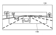
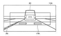
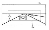
後方カメラ110は、車両100の後方に後方を向くように配置され、車両100の後方を撮影する。後方カメラ110は、水平方向の画角が例えば90〜180°、上下方向の画角が例えば45〜90°である。例えば、後方カメラ110は、図4に示すような、第一映像データ(後方映像データ)110Aを撮影している。図4は、第一実施形態に係る車両用表示システムの後方カメラで撮影された映像データの一例を示す図である。後方カメラ110は、リヤビューモニタ140に表示させる範囲より広い範囲の映像を撮影可能であるが、リヤビューモニタ140を用いて車両100の運転者が適切に後方を認識できるような範囲を切出してリヤビューモニタ140に表示する。後方カメラ110は、撮影した第一映像データ110Aを車両用表示制御装置10の映像データ取得部40の後方映像データ取得部42へ出力する。   The rear camera 110 is disposed behind the vehicle 100 so as to face the rear, and images the rear of the vehicle 100. The rear camera 110 has an angle of view in the horizontal direction of, for example, 90 to 180 °, and an angle of view in the vertical direction of, for example, 45 to 90 °. For example, the rear camera 110 captures first video data (rear video data) 110A as shown in FIG. FIG. 4 is a diagram illustrating an example of video data captured by the rear camera of the vehicle display system according to the first embodiment. The rear camera 110 can shoot an image in a wider range than the range displayed on the rear view monitor 140, but the rear view monitor 140 is used to cut out a range in which the driver of the vehicle 100 can properly recognize the rear. 140. The rear camera 110 outputs the captured first video data 110 </ b> A to the rear video data acquisition unit 42 of the video data acquisition unit 40 of the vehicle display control device 10.

右側後方カメラ120は、車両100の右側方に後方を向くように配置され、車両100の右側方を撮影する。右側後方カメラ120は、右サイドビューモニタ150による確認範囲を撮影する。右側後方カメラ120は、水平方向の画角が例えば15〜45°、上下方向の画角が例えば15〜45°である。右側後方カメラ120は、角度調節自在である。右側後方カメラ120は、撮影した映像(側後方映像データ)を車両用表示制御装置10の映像データ取得部40の側後方映像データ取得部41へ出力する。   The right rear camera 120 is disposed to face the right side of the vehicle 100 and photographs the right side of the vehicle 100. The right rear camera 120 captures a confirmation range by the right side view monitor 150. The right rear camera 120 has a horizontal angle of view of, for example, 15 to 45 °, and a vertical angle of view of, for example, 15 to 45 °. The right rear camera 120 is adjustable in angle. The right rear camera 120 outputs the captured video (side rear video data) to the side rear video data acquisition unit 41 of the video data acquisition unit 40 of the vehicle display control device 10.

左側後方カメラ130は、車両100の左側方に後方を向くように配置され、車両100の左側方を撮影する。左側後方カメラ130は、左サイドビューモニタ160による確認範囲を撮影する。左側後方カメラ130は、水平方向の画角が例えば15〜45°、上下方向の画角が例えば15〜45°である。左側後方カメラ130は、角度調節自在である。左側後方カメラ130は、撮影した映像(側後方映像データ)を車両用表示制御装置10の映像データ取得部40の側後方映像データ取得部41へ出力する。   The left rear camera 130 is disposed to face the left side of the vehicle 100 and photographs the left side of the vehicle 100. The left rear camera 130 captures a confirmation range by the left side view monitor 160. The left rear camera 130 has a horizontal angle of view of, for example, 15 to 45 °, and a vertical angle of view of, for example, 15 to 45 °. The left rear camera 130 is adjustable in angle. The left rear camera 130 outputs the captured video (side rear video data) to the side rear video data acquisition unit 41 of the video data acquisition unit 40 of the vehicle display control device 10.

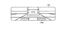
リヤビューモニタ140は、一例としては電子ルームミラーである。リヤビューモニタ140を電子ルームミラーとして用いる場合は、後方を光学的な反射により確認するためのハーフミラーの有無は問わない。リヤビューモニタ140は、例えば、液晶ディスプレイ(LCD:Liquid Crystal Display)または有機EL(Organic Electro−Luminescence)ディスプレイなどを含むディスプレイである。リヤビューモニタ140は、車両用表示制御装置10の表示制御部70から出力された映像信号に基づき、車両100の後方映像を表示する。具体的に、リヤビューモニタ140は、図5に示すような後方映像を表示する。図5は、第一実施形態に係る車両用表示システムのリヤビューモニタに表示される映像の一例を示す図である。リヤビューモニタ140は、運転者から視認容易な位置に配置されている。本実施形態では、リヤビューモニタ140は、ウィンドシールド101の車幅方向の中央上部に配置されている。または、リヤビューモニタ140は、ダッシュボード102やヘッドライナーに埋め込まれていてもよい。   The rear view monitor 140 is an electronic room mirror as an example. When the rear view monitor 140 is used as an electronic room mirror, it does not matter whether there is a half mirror for confirming the rear by optical reflection. The rear view monitor 140 is a display including, for example, a liquid crystal display (LCD) or an organic EL-Organic Electro-Luminescence (EL) display. The rear view monitor 140 displays a rear image of the vehicle 100 based on the video signal output from the display control unit 70 of the vehicle display control device 10. Specifically, the rear view monitor 140 displays a rear image as shown in FIG. FIG. 5 is a diagram illustrating an example of an image displayed on the rear view monitor of the vehicle display system according to the first embodiment. The rear view monitor 140 is disposed at a position that is easily visible to the driver. In the present embodiment, the rear view monitor 140 is disposed at the center upper portion of the windshield 101 in the vehicle width direction. Alternatively, the rear view monitor 140 may be embedded in the dashboard 102 or the head liner.

リヤビューモニタ140は、大きさ、形状は限定されない。例えば、リヤビューモニタ140は、従来の光学式のルームミラーと同様な大きさ、形状であってもよい。または、例えば、リヤビューモニタ140は、従来の光学式のルームミラーに比べて車幅方向の幅が広くてもよい。または、例えば、リヤビューモニタ140は、従来の光学式のルームミラーに比べて縦方向の幅が広くてもよい。   The size and shape of the rear view monitor 140 are not limited. For example, the rear view monitor 140 may be the same size and shape as a conventional optical room mirror. Alternatively, for example, the rear view monitor 140 may be wider in the vehicle width direction than a conventional optical rearview mirror. Alternatively, for example, the rear view monitor 140 may be wider in the vertical direction than a conventional optical room mirror.

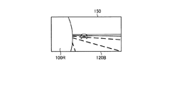
右サイドビューモニタ150は、例えば、液晶ディスプレイまたは有機ELディスプレイなどを含むディスプレイである。右サイドビューモニタ150は、車両用表示制御装置10の表示制御部70から出力された映像信号に基づき、車両100の右側後方映像を表示する。具体的に、右サイドビューモニタ150は、図6に示すような右側後方映像を表示する。図6は、第一実施形態に係る車両用表示システムの右サイドビューモニタに表示される映像の一例を示す図である。右サイドビューモニタ150には、車両100の右側方の車体100Rが映り込んでいる。右サイドビューモニタ150は、運転者から視認容易な位置に配置されている。本実施形態では、右サイドビューモニタ150は、ダッシュボード102の車幅方向の右側に配置されている。   The right side view monitor 150 is a display including a liquid crystal display or an organic EL display, for example. The right side view monitor 150 displays a right rear video of the vehicle 100 based on the video signal output from the display control unit 70 of the vehicle display control device 10. Specifically, the right side view monitor 150 displays a right rear video as shown in FIG. FIG. 6 is a diagram illustrating an example of an image displayed on the right side view monitor of the vehicle display system according to the first embodiment. On the right side view monitor 150, the vehicle body 100R on the right side of the vehicle 100 is reflected. The right side view monitor 150 is disposed at a position that is easily visible to the driver. In the present embodiment, the right side view monitor 150 is disposed on the right side of the dashboard 102 in the vehicle width direction.

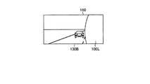
左サイドビューモニタ160は、例えば、液晶ディスプレイまたは有機ELディスプレイを含むディスプレイである。左サイドビューモニタ160は、車両用表示制御装置10の表示制御部70から出力された映像信号に基づき、車両100の左側後方映像を表示する。例えば、左サイドビューモニタ160は、図7に示すような左側後方映像を表示する。図7は、第一実施形態に係る車両用表示システムの左サイドビューモニタに表示される映像の一例を示す図である。左サイドビューモニタ160には、車両100の左側方の車体100Lが映り込んでいる。左サイドビューモニタ160は、運転者から視認容易な位置に配置されている。本実施形態では、左サイドビューモニタ160は、ダッシュボード102の車幅方向の左側に配置されている。   The left side view monitor 160 is a display including a liquid crystal display or an organic EL display, for example. The left side view monitor 160 displays a left rear video of the vehicle 100 based on the video signal output from the display control unit 70 of the vehicle display control device 10. For example, the left side view monitor 160 displays a left rear image as shown in FIG. FIG. 7 is a diagram illustrating an example of an image displayed on the left side view monitor of the vehicle display system according to the first embodiment. On the left side view monitor 160, the vehicle body 100L on the left side of the vehicle 100 is reflected. The left side view monitor 160 is disposed at a position that is easily visible to the driver. In the present embodiment, the left side view monitor 160 is disposed on the left side of the dashboard 102 in the vehicle width direction.

図3に戻って、車両用表示制御装置10は、記憶部20と、制御部30とを有する。   Returning to FIG. 3, the vehicle display control apparatus 10 includes a storage unit 20 and a control unit 30.

記憶部20は、車両用表示制御装置10における各種処理に要するデータおよび各種処理結果を記憶する。記憶部20は、例えば、RAM(Random Access Memory)、ROM(Read Only Memory)、フラッシュメモリ(Flash Memory)などの半導体メモリ素子、または、ハードディスク、光ディスク、ネットワークを介した外部記憶装置などの記憶装置である。または、図示しない通信装置を介して無線接続される外部記憶装置であってもよい。   The storage unit 20 stores data and various processing results required for various processes in the vehicle display control apparatus 10. The storage unit 20 is, for example, a semiconductor memory device such as a RAM (Random Access Memory), a ROM (Read Only Memory), a flash memory (Flash Memory), or a storage device such as a hard disk, an optical disk, or an external storage device via a network. It is. Alternatively, an external storage device that is wirelessly connected via a communication device (not shown) may be used.

制御部30は、例えば、CPU(Central Processing Unit)などで構成された演算処理装置である。制御部30は、映像データ取得部40と、映像処理部50と、走行状況情報取得部60と、表示制御部70とを含む。制御部30は、記憶部20に記憶されているプログラムに含まれる命令を実行する。   The control unit 30 is an arithmetic processing unit configured with, for example, a CPU (Central Processing Unit). The control unit 30 includes a video data acquisition unit 40, a video processing unit 50, a traveling state information acquisition unit 60, and a display control unit 70. The control unit 30 executes instructions included in the program stored in the storage unit 20.

映像データ取得部40は、車両100の後方および側後方を撮影した映像を取得する。映像データ取得部40が取得する映像データは、例えば、毎秒60フレームの画像が連続した映像データである。映像データ取得部40は、側後方映像データ取得部41と、後方映像データ取得部42とを有する。側後方映像データ取得部41は、右側後方カメラ120および左側後方カメラ130が出力した第二映像データを取得する。側後方映像データ取得部41は、取得した第二映像データを切出部51に出力する。後方映像データ取得部42は、後方カメラ110が出力した第一映像データ110Aを取得する。後方映像データ取得部42は、取得した第一映像データ110Aを切出部51に出力する。   The video data acquisition unit 40 acquires a video obtained by photographing the rear and side rear of the vehicle 100. The video data acquired by the video data acquisition unit 40 is, for example, video data in which images of 60 frames per second are continuous. The video data acquisition unit 40 includes a side rear video data acquisition unit 41 and a rear video data acquisition unit 42. The side rear video data acquisition unit 41 acquires the second video data output from the right rear camera 120 and the left rear camera 130. The side rear video data acquisition unit 41 outputs the acquired second video data to the cutout unit 51. The rear video data acquisition unit 42 acquires the first video data 110 </ b> A output from the rear camera 110. The rear video data acquisition unit 42 outputs the acquired first video data 110 </ b> A to the cutout unit 51.

切出部51は、第一映像データ110Aからリヤビューモニタ140に表示する後方映像データ110Bを切出す。切出部51は、第一映像データ110Aから第一映像データ110Aの一部を切出す。第一映像データ110Aのどの範囲を切出すかは、あらかじめ登録され記憶されている。本実施形態では、第一映像データ110Aの中央部を切出す。切出部51は、切出した後方映像データ110Bを映像合成部52と表示制御部70に出力する。   The cutout unit 51 cuts out the rear video data 110B to be displayed on the rear view monitor 140 from the first video data 110A. The cutout unit 51 cuts out a part of the first video data 110A from the first video data 110A. Which range of the first video data 110A is to be cut out is registered and stored in advance. In the present embodiment, the central portion of the first video data 110A is cut out. The cutout unit 51 outputs the cut out rear video data 110 </ b> B to the video composition unit 52 and the display control unit 70.

切出部51は、第二映像データから、右サイドビューモニタ150および左サイドビューモニタ160に表示する右側後方映像データ120Bおよび左側後方映像データ130Bを切出す。切出部51は、第二映像データから第二映像データの一部を切出す。第二映像データのどの範囲を切出すかは、あらかじめ登録され記憶されている。切出部51は、切出した右側後方映像データ120Bおよび左側後方映像データ130Bを映像合成部52と表示制御部70に出力する。切出部51で切出された、後方映像データ110Bと右側後方映像データ120Bおよび左側後方映像データ130Bとは、同期している。   The cutout unit 51 cuts out the right rear video data 120B and the left rear video data 130B to be displayed on the right side view monitor 150 and the left side view monitor 160 from the second video data. The cutout unit 51 cuts out a part of the second video data from the second video data. Which range of the second video data is to be cut out is registered and stored in advance. The cutout unit 51 outputs the cut out right rear video data 120B and the left rear video data 130B to the video composition unit 52 and the display control unit 70. The rear video data 110B, the right rear video data 120B, and the left rear video data 130B cut out by the cutout unit 51 are synchronized.

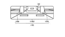
映像合成部52は、走行状況情報取得部60が取得した走行状況に応じて、後方映像データ110Bの左右上方に右側後方映像データ120Bおよび左側後方映像データ130Bを合成した後方映像データ110Cを生成する。本実施形態では、映像合成部52は、走行状況情報取得部60が、車両100が後退することを示す情報を取得したとき、後方映像データ110Bの左右上方に右側後方映像データ120Bおよび左側後方映像データ130Bを合成した後方映像データ110Cを生成する。例えば、映像合成部52は、図8に示すような合成した後方映像データ110Cを生成する。図8は、第一実施形態に係る車両用表示システムのリヤビューモニタに表示される映像の他の例を示す図である。本実施形態において、合成した後方映像データ110Cにおける右側後方映像データ120Bおよび左側後方映像データ130Bの大きさは、リヤビューモニタ140の表示面の縦方向サイズにおける上方約二分の一程度の大きさである。合成した後方映像データ110Cにおける右側後方映像データ120Bおよび左側後方映像データ130Bの大きさは、リヤビューモニタ140の表示面の横方向サイズにおける左右約三分の一程度の大きさである。映像合成部52は、合成した後方映像データ110Cを表示制御部70に出力する。   The video composition unit 52 generates the rear video data 110C by compositing the right rear video data 120B and the left rear video data 130B on the left and right upper sides of the rear video data 110B according to the driving situation acquired by the driving situation information acquisition unit 60. . In the present embodiment, when the traveling state information acquisition unit 60 acquires information indicating that the vehicle 100 moves backward, the video composition unit 52 has the right rear video data 120B and the left rear video on the left and right upper sides of the rear video data 110B. The rear video data 110C obtained by combining the data 130B is generated. For example, the video composition unit 52 generates the synthesized rear video data 110C as shown in FIG. FIG. 8 is a diagram illustrating another example of an image displayed on the rear view monitor of the vehicle display system according to the first embodiment. In the present embodiment, the size of the right rear video data 120B and the left rear video data 130B in the synthesized rear video data 110C is about half of the upper size in the vertical size of the display surface of the rear view monitor 140. . The size of the right rear video data 120B and the left rear video data 130B in the synthesized rear video data 110C is about one third of the horizontal size of the display surface of the rear view monitor 140. The video composition unit 52 outputs the synthesized rear video data 110 </ b> C to the display control unit 70.

ここで、後方映像データ110Bにおいて、運転者にとって運転中の安全確認の必要度が高い範囲は、後方映像データ110Bの中央部分および左右下方部分の範囲である。後方映像データ110Bの中央部分には、走行路が直進であるときの消失点が含まれる。言い換えると、後方映像データ110Bの左右上方の範囲は、運転者にとって運転中の安全確認の必要度が低い。このため、映像合成部52は、後方映像データ110Bの左右上方に右側後方映像データ120Bおよび左側後方映像データ130Bを合成する。本実施形態では、合成した後方映像データ110Cにおける右側後方映像データ120Bおよび左側後方映像データ130Bの大きさをリヤビューモニタ140の表示面の縦方向サイズにおける上方約二分の一程度とし、映像が重なる範囲を小さくしている。本実施形態では、合成した後方映像データ110Cにおける右側後方映像データ120Bおよび左側後方映像データ130Bの大きさをリヤビューモニタ140の表示面の横方向サイズにおける左右約三分の一程度の大きさとし、映像が重なる範囲を小さくしている。また、後方映像データ110Bと右側後方映像データ120Bおよび左側後方映像データ130Bとの表示される境界が明瞭となるように、右側後方映像データ120Bおよび左側後方映像データ130Bを枠線等で囲うことが効果的である。   Here, in the rear video data 110B, the range in which the driver needs to confirm safety while driving is the range of the center portion and the left and right lower portions of the rear video data 110B. The center portion of the rear video data 110B includes a vanishing point when the travel path is straight ahead. In other words, the upper left and right range of the rear video data 110B is less necessary for the driver to confirm safety during driving. Therefore, the video composition unit 52 synthesizes the right rear video data 120B and the left rear video data 130B on the left and right upper sides of the rear video data 110B. In the present embodiment, the size of the right rear video data 120B and the left rear video data 130B in the synthesized rear video data 110C is about one half above the vertical size of the display surface of the rear view monitor 140, and the range in which the images overlap Is made smaller. In the present embodiment, the size of the right rear video data 120B and the left rear video data 130B in the synthesized rear video data 110C is about one third of the horizontal size of the display surface of the rear view monitor 140. The overlapping range is made smaller. Further, the right rear video data 120B and the left rear video data 130B may be surrounded by a frame line or the like so that the boundary between the rear video data 110B, the right rear video data 120B, and the left rear video data 130B is clear. It is effective.

走行状況情報取得部60は、車両100に備えられたCAN(Controller Area Network)に接続されOBD(On Board Diagnosis)IIデータなどを取得することで、車両100における様々な走行状況情報を取得する。走行状況情報取得部60は、車両100の走行状況情報として、車両100が後退することを示す情報を取得する。より詳しくは、走行状況情報取得部60は、例えば、シフトポジション情報または進行方向情報を取得する。走行状況情報取得部60は、取得した走行状況情報を映像合成部52に出力する。   The traveling state information acquisition unit 60 is connected to a CAN (Controller Area Network) provided in the vehicle 100 and acquires OBD (On Board Diagnostics) II data and the like, thereby acquiring various traveling state information in the vehicle 100. The traveling state information acquisition unit 60 acquires information indicating that the vehicle 100 moves backward as the traveling state information of the vehicle 100. More specifically, the traveling state information acquisition unit 60 acquires shift position information or traveling direction information, for example. The traveling state information acquisition unit 60 outputs the acquired traveling state information to the video composition unit 52.

表示制御部70は、毎フレームまたは所定フレームごとに、後方映像データ110Bまたは映像合成部52が合成した後方映像データ110Cをリヤビューモニタ140に出力する。   The display control unit 70 outputs the rear video data 110B or the rear video data 110C synthesized by the video synthesis unit 52 to the rear view monitor 140 every frame or every predetermined frame.

表示制御部70は、毎フレームまたは所定フレームごとに、右側後方映像データ120Bを右サイドビューモニタ150に表示させる。言い換えると、表示制御部70は、右側後方カメラ120で撮影された第二映像データに基づく右側後方映像データ120Bを右サイドビューモニタ150に表示させる。   The display control unit 70 causes the right side view monitor 150 to display the right rear video data 120B every frame or every predetermined frame. In other words, the display control unit 70 causes the right side view monitor 150 to display the right rear video data 120B based on the second video data captured by the right rear camera 120.

表示制御部70は、毎フレームまたは所定フレームごとに、左側後方映像データ130Bを左サイドビューモニタ160に表示させる。言い換えると、表示制御部70は、左側後方カメラ130で撮影された第二映像データに基づく左側後方映像データ130Bを左サイドビューモニタ160に表示させる。表示制御部70は、リヤビューモニタ140に表示される後方映像データ110Bまたは合成した後方映像データ110Cと、右サイドビューモニタ150に表示される右側後方映像データ120Bと、左サイドビューモニタ160に表示される左側後方映像データ130Bとが同期するように表示を制御する。   The display control unit 70 displays the left rear video data 130B on the left side view monitor 160 every frame or every predetermined frame. In other words, the display control unit 70 causes the left side view monitor 160 to display the left rear video data 130 </ b> B based on the second video data captured by the left rear camera 130. The display control unit 70 is displayed on the rear video data 110B or the synthesized rear video data 110C displayed on the rear view monitor 140, the right rear video data 120B displayed on the right side view monitor 150, and the left side view monitor 160. The display is controlled so as to be synchronized with the left rear video data 130B.

次に、図9を用いて、制御部30における情報処理について説明する。図9は、第一実施形態に係る車両用表示システムの車両用表示制御装置の制御部における処理の流れを示すフローチャートである。   Next, information processing in the control unit 30 will be described with reference to FIG. FIG. 9 is a flowchart showing the flow of processing in the control unit of the vehicle display control apparatus of the vehicle display system according to the first embodiment.

図9の処理における前提としては、車両100が動作している期間中、リヤビューモニタ140に後方映像データ110Bが表示され、右サイドビューモニタ150に右側後方映像データ120B、左サイドビューモニタ160に左側後方映像データ130Bが表示されている状態である。また、このような状態において、制御部30は、走行状況情報取得部60で走行状況の取得を継続している。より詳しくは、制御部30は、走行状況情報取得部60で、例えば、シフトポジション情報または進行方向情報を含む走行状況情報が発生したか常時監視している。   As a premise in the processing of FIG. 9, while the vehicle 100 is operating, the rear video data 110B is displayed on the rear view monitor 140, the right rear video data 120B is displayed on the right side view monitor 150, and the left video is displayed on the left side view monitor 160. This is a state in which the rear video data 130B is displayed. Further, in such a state, the control unit 30 continues to acquire the traveling state by the traveling state information acquisition unit 60. More specifically, the control unit 30 constantly monitors whether or not traveling state information including shift position information or traveling direction information is generated by the traveling state information acquisition unit 60, for example.

制御部30は、後退トリガの有無を判定する(ステップS11)。後退トリガとは、例えば、シフトポジションが「リバース」とされたことをいう。または、後退トリガとは、車両100の進行方向が車両100の前後方向の後方となったことをいう。制御部30は、走行状況情報取得部60で取得した走行状況情報に基づいて、後退トリガの有無を判定する。制御部30は、後退トリガがないと判定した場合(ステップS11でNo)、ステップS11の処理を再度実行する。制御部30は、後退トリガがあると判定した場合(ステップS11でYes)、ステップS12に進む。   The control unit 30 determines whether or not there is a reverse trigger (step S11). The reverse trigger means that, for example, the shift position is “reverse”. Alternatively, the reverse trigger means that the traveling direction of the vehicle 100 is the rear of the vehicle 100 in the front-rear direction. The control unit 30 determines the presence or absence of a reverse trigger based on the traveling state information acquired by the traveling state information acquisition unit 60. When it is determined that there is no reverse trigger (No in step S11), the control unit 30 executes the process of step S11 again. If it is determined that there is a reverse trigger (Yes in step S11), the control unit 30 proceeds to step S12.

ステップS11において、後退トリガがあると判定された場合、制御部30は、合成した後方映像データ110Cを生成する(ステップS12)。より詳しくは、制御部30は、切出部51で、第一映像データ110Aから後方映像データ110Bを切出させる。そして、制御部30は、映像合成部52で、後方映像データ110Bの左右上方に右側後方映像データ120Bおよび左側後方映像データ130Bを合成した後方映像データ110Cを生成させる。   If it is determined in step S11 that there is a backward trigger, the control unit 30 generates the synthesized rear video data 110C (step S12). More specifically, the control unit 30 causes the cutout unit 51 to cut out the rear video data 110B from the first video data 110A. Then, the control unit 30 causes the video composition unit 52 to generate the rear video data 110C obtained by combining the right rear video data 120B and the left rear video data 130B on the left and right upper sides of the rear video data 110B.

制御部30は、ステップS12で生成した、合成した後方映像データ110Cを表示する(ステップS13)。より詳しくは、制御部30は、表示制御部70で、通常の後方映像データ110Bまたは合成した後方映像データ110Cをリヤビューモニタ140に表示させる。   The control unit 30 displays the synthesized rear video data 110C generated in step S12 (step S13). More specifically, the control unit 30 causes the display control unit 70 to display the normal rear video data 110B or the synthesized rear video data 110C on the rear view monitor 140.

走行状況情報取得部60は、ステップS11で後退トリガがあると判定された後も継続して走行状況を取得している。より詳しくは、制御部30は、走行状況情報取得部60で走行状況の取得を継続している。   The traveling state information acquisition unit 60 continues to acquire the traveling state even after it is determined in step S11 that there is a reverse trigger. More specifically, the control unit 30 continues to acquire the traveling state by the traveling state information acquisition unit 60.

ステップS13において、合成した後方映像データ110Cを表示している期間において、制御部30は、走行状況情報取得部60で取得した走行状況情報に基づいて、後退終了を判定する(ステップS14)。より詳しくは、制御部30は、走行状況情報取得部60で取得した走行状況情報に基づいて、後退トリガの解除を判定する。制御部30は、後退トリガの解除がないと判定した場合(ステップS14でNo)、合成した後方映像データ110Cの表示を継続する。制御部30は、後退トリガの解除があると判定された場合(ステップS14でYes)、制御部30は、後方映像データ110Bを生成し(ステップS15)、後方映像データ110Bを表示する(ステップS16)。すなわち、ステップS15およびステップS16は、ステップS11において後退トリガが検出される以前と同様、通常の後方映像データBの表示が開始、継続される。   In the period in which the synthesized rear video data 110C is displayed in step S13, the control unit 30 determines the end of the reverse based on the traveling state information acquired by the traveling state information acquiring unit 60 (step S14). More specifically, the control unit 30 determines the release of the reverse trigger based on the traveling state information acquired by the traveling state information acquisition unit 60. When it is determined that the reverse trigger is not released (No in step S14), the control unit 30 continues to display the synthesized rear video data 110C. When it is determined that the reverse trigger is released (Yes in step S14), the control unit 30 generates the rear video data 110B (step S15) and displays the rear video data 110B (step S16). ). That is, in steps S15 and S16, display of normal rear video data B is started and continued as before the backward trigger is detected in step S11.

制御部30は、後退トリガの検出ごとに、上記の処理を繰り返す。   The control unit 30 repeats the above process every time a reverse trigger is detected.

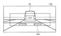
図10ないし図14を用いて、制御部30における情報処理の具体例を説明する。図10は、第一実施形態に係る車両用表示システムの後方カメラで撮影された映像データの他の例を示す図である。図11は、第一実施形態に係る車両用表示システムのリヤビューモニタに表示される映像の他の例を示す図である。図12は、第一実施形態に係る車両用表示システムの右サイドビューモニタに表示される映像の他の例を示す図である。図13は、第一実施形態に係る車両用表示システムの左サイドビューモニタに表示される映像の他の例を示す図である。図14は、第一実施形態に係る車両用表示システムのリヤビューモニタに表示される映像の他の例を示す図である。車両100は、シフトポジション「リバース」が選択されている。図10に示す第一映像データ110Aには、車両100の後方に駐車されている他車両201が映っている。制御部30は、ステップS11において、後退トリガがあると判定する(ステップS11でYes)。そして、制御部30は、ステップS12において、切出部51で、図10に示す第一映像データ110Aから、図11に示す後方映像データ110Bを切出させる。そして、制御部30は、映像合成部52で、後方映像データ110Bの右上方に、図12に示す右側後方映像データ120Bを合成し、左上方に図13に示す左側後方映像データ130Bを合成して、合成した後方映像データ110Cを生成させる。そして、制御部30は、ステップS13において、表示制御部70で、リヤビューモニタ140の表示面に、図14に示す合成した後方映像データ110Cを表示させる。   A specific example of information processing in the control unit 30 will be described with reference to FIGS. 10 to 14. FIG. 10 is a diagram illustrating another example of the video data captured by the rear camera of the vehicle display system according to the first embodiment. FIG. 11 is a diagram illustrating another example of an image displayed on the rear view monitor of the vehicle display system according to the first embodiment. FIG. 12 is a diagram illustrating another example of an image displayed on the right side view monitor of the vehicle display system according to the first embodiment. FIG. 13 is a diagram illustrating another example of an image displayed on the left side view monitor of the vehicle display system according to the first embodiment. FIG. 14 is a diagram illustrating another example of an image displayed on the rear view monitor of the vehicle display system according to the first embodiment. In the vehicle 100, the shift position “reverse” is selected. In the first video data 110 </ b> A shown in FIG. 10, another vehicle 201 parked behind the vehicle 100 is shown. In step S11, the control unit 30 determines that there is a reverse trigger (Yes in step S11). In step S12, the control unit 30 causes the cutout unit 51 to cut out the rear video data 110B shown in FIG. 11 from the first video data 110A shown in FIG. Then, the control unit 30 synthesizes the right rear video data 120B shown in FIG. 12 on the upper right side of the rear video data 110B and the left rear video data 130B shown in FIG. Thus, the synthesized rear video data 110C is generated. In step S <b> 13, the control unit 30 causes the display control unit 70 to display the synthesized rear video data 110 </ b> C shown in FIG. 14 on the display surface of the rear view monitor 140.

このようにして、車両用表示システム1は、走行状況情報取得部60が取得した走行状況に応じて、合成した後方映像データ110Cをリヤビューモニタ140の表示面に表示させる。   In this way, the vehicle display system 1 displays the synthesized rear video data 110C on the display surface of the rear view monitor 140 in accordance with the driving situation acquired by the driving condition information acquisition unit 60.

上述したように、本実施形態は、走行状況情報取得部60が取得した走行状況に応じて、合成した後方映像データ110Cをリヤビューモニタ140の表示面に表示させる。本実施形態では、車両100の後退時、後方映像データ110Bの左右上方に右側後方映像データ120Bおよび左側後方映像データ130Bを合成した後方映像データ110Cをリヤビューモニタ140の表示面に表示させる。これにより、本実施形態は、車両100の後退時で、リヤビューモニタ140の表示面で、車両100の後方とともに、車両100の側後方を確認することができる。このため、本実施形態は、運転者の視線移動を抑制することができる。より詳しくは、本実施形態は、リヤビューモニタ140から視線移動して右サイドビューモニタ150および左サイドビューモニタ160を視認しなくても、路側方向の側後方を確認することができる。本実施形態は、運転者の後方及び側後方の確認に要する時間を低減することができる。このように、車両用表示システム1は、適切な車両100周辺の確認を可能にすることができる。   As described above, in the present embodiment, the synthesized rear image data 110C is displayed on the display surface of the rear view monitor 140 in accordance with the traveling situation acquired by the traveling situation information acquisition unit 60. In the present embodiment, when the vehicle 100 moves backward, the rear video data 110C obtained by combining the right rear video data 120B and the left rear video data 130B on the left and right upper sides of the rear video data 110B is displayed on the display surface of the rear view monitor 140. Accordingly, in the present embodiment, the rear side of the vehicle 100 can be confirmed along with the rear side of the vehicle 100 on the display surface of the rear view monitor 140 when the vehicle 100 moves backward. For this reason, this embodiment can suppress a driver | operator's eyes | visual_axis movement. More specifically, in the present embodiment, it is possible to confirm the rear side in the roadside direction without moving the line of sight from the rear view monitor 140 and visually recognizing the right side view monitor 150 and the left side view monitor 160. This embodiment can reduce the time required for confirmation of the driver's rear and side rear. As described above, the vehicle display system 1 can make it possible to check the vicinity of the appropriate vehicle 100.

本実施形態によれば、車両100の後退時、合成した後方映像データ110Cをリヤビューモニタ140の表示面に表示させる。このため、本実施形態によれば、運転者による操作によらず自動で、リヤビューモニタ140の表示面で、車両100の後方とともに、車両100の側後方を表示させることができる。このように、車両用表示システム1は、適切な車両100周辺の確認を可能にすることができる。   According to the present embodiment, when the vehicle 100 moves backward, the synthesized rear video data 110 </ b> C is displayed on the display surface of the rear view monitor 140. For this reason, according to the present embodiment, the rear side of the vehicle 100 can be displayed on the display surface of the rear view monitor 140 together with the rear side of the vehicle 100 automatically regardless of the operation by the driver. As described above, the vehicle display system 1 can make it possible to check the vicinity of the appropriate vehicle 100.

本実施形態によれば、車両100の後退時、所定条件を満たす場合に、合成した後方映像データ110Cをリヤビューモニタ140の表示面に表示させる。言い換えると、本実施形態によれば、所定条件を満たす場合、合成した後方映像データ110Cを表示させ、その他の場合、後方映像データ110Bを表示させる。このため、本実施形態は、車両100の後退時、運転者が必要とするタイミングで、適切な情報量の映像を表示することができる。   According to the present embodiment, when the vehicle 100 moves backward, when the predetermined condition is satisfied, the synthesized rear image data 110C is displayed on the display surface of the rear view monitor 140. In other words, according to the present embodiment, when the predetermined condition is satisfied, the synthesized rear video data 110C is displayed, and in the other cases, the rear video data 110B is displayed. For this reason, this embodiment can display an image with an appropriate amount of information at the timing required by the driver when the vehicle 100 moves backward.

本実施形態によれば、映像合成部52は、後方映像データ110Bの左右上方に右側後方映像データ120Bおよび左側後方映像データ130Bを合成する。言い換えると、本実施形態によれば、映像合成部52は、後方映像データ110Bの消失点より下方の範囲は、右側後方映像データ120Bおよび左側後方映像データ130Bが重なる範囲を小さくする。言い換えると、後方映像データ110Bの左右上方は、後退時の後方確認の優先度が低いとともに、右側後方映像データ120Bおよび左側後方映像データ130Bによる確認がより適切である。このため、本実施形態は、運転者にとって運転中の安全確認の必要度が高い範囲は、走行状況によらず、従来の光学式のルームミラーと同様に後方を確認することができる。   According to the present embodiment, the video composition unit 52 synthesizes the right rear video data 120B and the left rear video data 130B on the left and right upper sides of the rear video data 110B. In other words, according to the present embodiment, the video composition unit 52 reduces the range below the vanishing point of the rear video data 110B so that the right rear video data 120B and the left rear video data 130B overlap. In other words, in the upper left and right of the rear video data 110B, the priority of the backward confirmation at the time of backward movement is low, and the confirmation by the right rear video data 120B and the left rear video data 130B is more appropriate. For this reason, this embodiment can confirm the back of the range where the necessity of safety confirmation during driving is high for the driver as in the case of the conventional optical room mirror, regardless of the traveling state.

[第二実施形態]
図15ないし図17を参照しながら、本実施形態に係る車両用表示システム1について説明する。図15は、第二実施形態に係る車両用表示システムの車両用表示制御装置の制御部における処理の流れを示すフローチャートである。図16は、第二実施形態に係る車両用表示システムの後方カメラで撮影された映像データの一例を示す図である。図17は、第二実施形態に係る車両用表示システムのリヤビューモニタに表示される映像の一例を示す図である。本実施形態に係る車両用表示システム1は、基本的な構成は第一実施形態の車両用表示システム1と同様である。以下の説明においては、車両用表示システム1と同様の構成要素には、同一の符号または対応する符号を付し、その詳細な説明は省略する。本実施形態の車両用表示システム1は、切出部51および制御部30における情報処理が第一実施形態の車両用表示システム1と異なる。
[Second Embodiment]
The vehicle display system 1 according to the present embodiment will be described with reference to FIGS. 15 to 17. FIG. 15 is a flowchart showing a flow of processing in the control unit of the vehicle display control device of the vehicle display system according to the second embodiment. FIG. 16 is a diagram illustrating an example of video data captured by the rear camera of the vehicle display system according to the second embodiment. FIG. 17 is a diagram illustrating an example of an image displayed on the rear view monitor of the vehicle display system according to the second embodiment. The vehicle display system 1 according to the present embodiment has the same basic configuration as the vehicle display system 1 of the first embodiment. In the following description, the same components as those of the vehicle display system 1 are denoted by the same reference numerals or corresponding reference numerals, and detailed description thereof is omitted. The vehicle display system 1 according to the present embodiment is different from the vehicle display system 1 according to the first embodiment in information processing in the cutout unit 51 and the control unit 30.

切出部51は、走行状況に応じて、第一映像データ110Aからの切出範囲を、通常の後方映像データ110Bの切出範囲よりも下方に設定する。より詳しくは、切出部51は、表示制御部70が映像合成部52で合成した後方映像データ110Cを表示させるとき、合成していない通常の後方映像データ110Bを表示させるときより下方を切出すように第一映像データ110Aからの切出範囲を設定する。例えば、合成していない通常の後方映像データ110Bを表示させるときの切出範囲より、所定画素下方を含むように切出範囲を設定する。言い換えると、切出部51は、表示制御部70が映像合成部52で合成した後方映像データ110Cを表示させるとき、より車両100に近い位置を切出範囲に含むように設定する。切出部51は、切出した後方映像データ110B2を映像合成部52と表示制御部70とに出力する。   The cutout unit 51 sets the cutout range from the first video data 110A to be lower than the cutout range of the normal rear video data 110B according to the traveling state. More specifically, when the display control unit 70 displays the rear video data 110C synthesized by the video synthesis unit 52, the cutout unit 51 cuts out the lower part than when displaying the normal rear video data 110B that is not synthesized. In this manner, the cut-out range from the first video data 110A is set. For example, the cutout range is set so as to include a predetermined pixel lower than the cutout range when displaying the normal uncombined rear video data 110B. In other words, when the display control unit 70 displays the rear video data 110C synthesized by the video synthesis unit 52, the cutout unit 51 sets a position closer to the vehicle 100 to be included in the cutout range. The cutout unit 51 outputs the cut out rear video data 110B2 to the video composition unit 52 and the display control unit 70.

次に、図15を用いて、制御部30における情報処理について説明する。図15に示すフローチャートのステップS21、ステップS24〜ステップS27の処理は、図9に示すフローチャートのステップS11、ステップS13〜ステップS16の処理と同様である。   Next, information processing in the control unit 30 will be described with reference to FIG. The processes in step S21 and steps S24 to S27 in the flowchart shown in FIG. 15 are the same as the processes in steps S11 and S13 to S16 in the flowchart shown in FIG.

制御部30は、切出範囲を下方にシフトして後方映像データ110B2を切出す(ステップS22)。   The control unit 30 shifts the cutout range downward to cut out the rear video data 110B2 (Step S22).

制御部30は、合成した後方映像データ110Cを生成する(ステップS23)。より詳しくは、制御部30は、切出部51で切出した後方映像データ110B2の左右上方に右側後方映像データ120Bおよび左側後方映像データ130Bを合成した後方映像データ110Cを生成させる。   The control unit 30 generates the synthesized rear video data 110C (step S23). More specifically, the control unit 30 generates the rear video data 110C obtained by combining the right rear video data 120B and the left rear video data 130B on the left and right upper sides of the rear video data 110B2 cut out by the cutout unit 51.

図16および図17を用いて、制御部30における情報処理の具体例を説明する。車両100は、シフトポジション「リバース」が選択されている。図16に示す第一映像データ110Aは、車両100の後方に駐車されている他車両201が映っている。制御部30は、ステップS21において、後退トリガがあると判定する(ステップS21でYes)。そして、制御部30は、ステップS22において、切出部51で、後方映像データ110Bの切出範囲を下方にシフトして、図16に示す第一映像データ110Aから後方映像データ110B2を切出させる。そして、制御部30は、ステップS23において、映像合成部52で、後方映像データ110B2の左右上方に右側後方映像データ120Bおよび左側後方映像データ130Bを合成した後方映像データ110Cを生成させる。そして、制御部30は、ステップS24において、表示制御部70で、リヤビューモニタ140の表示面に、図17に示す合成した後方映像データ110Cを表示させる。   A specific example of information processing in the control unit 30 will be described with reference to FIGS. 16 and 17. In the vehicle 100, the shift position “reverse” is selected. In the first video data 110 </ b> A shown in FIG. 16, the other vehicle 201 parked behind the vehicle 100 is shown. In step S21, the control unit 30 determines that there is a reverse trigger (Yes in step S21). In step S22, the control unit 30 causes the cutout unit 51 to shift the cutout range of the rear video data 110B downward to cut out the rear video data 110B2 from the first video data 110A shown in FIG. . In step S23, the control unit 30 causes the video composition unit 52 to generate the rear video data 110C obtained by combining the right rear video data 120B and the left rear video data 130B on the left and right upper sides of the rear video data 110B2. In step S24, the control unit 30 causes the display control unit 70 to display the synthesized rear video data 110C shown in FIG. 17 on the display surface of the rear view monitor 140.

このようにして、車両用表示システム1は、走行状況情報取得部60が取得した走行状況に応じて、合成していない通常の後方映像データ110Bより下方を切出し、合成した後方映像データ110Cをリヤビューモニタ140の表示面に表示させる。   In this way, the vehicle display system 1 cuts out the lower part of the normal rear image data 110B that has not been combined, and rearranges the combined rear image data 110C in the rear view according to the driving state acquired by the driving state information acquisition unit 60. It is displayed on the display surface of the monitor 140.

上述したように、本実施形態では、車両100の後退時、切出範囲を下方にシフトして切出した後方映像データ110B2の左右上方に右側後方映像データ120Bおよび左側後方映像データ130Bを合成し、合成した後方映像データ110Cをリヤビューモニタ140の表示面に表示させる。これにより、本実施形態は、リヤビューモニタ140の表示面で、車両100により近い位置を含んで後方を確認することができる。このように、車両用表示システム1は、適切な車両100周辺の確認を可能にすることができる。   As described above, in the present embodiment, when the vehicle 100 moves backward, the right rear video data 120B and the left rear video data 130B are synthesized on the left and right upper sides of the rear video data 110B2 that is extracted by shifting the cutout range downward. The synthesized rear video data 110C is displayed on the display surface of the rear view monitor 140. Accordingly, in the present embodiment, the rear side including the position closer to the vehicle 100 can be confirmed on the display surface of the rear view monitor 140. As described above, the vehicle display system 1 can make it possible to check the vicinity of the appropriate vehicle 100.

[第三実施形態]
図18ないし図21を参照しながら、本実施形態に係る車両用表示システム1Aについて説明する。図18は、第三実施形態に係る車両用表示システムの構成例を示すブロック図である。図19は、第三実施形態に係る車両用表示システムの車両用表示制御装置の制御部における処理の流れを示すフローチャートである。図20は、第三実施形態に係る車両用表示システムの後方カメラで撮影された映像データの一例を示す図である。図21は、第三実施形態に係る車両用表示システムのリヤビューモニタに表示される映像の一例を示す図である。本実施形態の車両用表示システム1Aは、検出部80と、認識辞書記憶部300とを有する点および制御部30Aにおける情報処理が第一実施形態の車両用表示システム1と異なる。
[Third embodiment]
A vehicle display system 1A according to the present embodiment will be described with reference to FIGS. FIG. 18 is a block diagram illustrating a configuration example of the vehicle display system according to the third embodiment. FIG. 19 is a flowchart illustrating a process flow in the control unit of the vehicle display control device of the vehicle display system according to the third embodiment. FIG. 20 is a diagram illustrating an example of video data captured by the rear camera of the vehicle display system according to the third embodiment. FIG. 21 is a diagram illustrating an example of an image displayed on the rear view monitor of the vehicle display system according to the third embodiment. The vehicle display system 1A of the present embodiment is different from the vehicle display system 1 of the first embodiment in that it includes a detection unit 80 and a recognition dictionary storage unit 300 and information processing in the control unit 30A.

認識辞書記憶部300は、例えば、車両、人物、壁、縁石、植物などを含む障害物の各方向視の形状、大きさ、色などのパターンを照合可能な認識辞書を記憶している。認識辞書記憶部300は、例えば、RAM、ROM、フラッシュメモリなどの半導体メモリ素子、または、ハードディスク、光ディスク、ネットワークを介した外部記憶装置などの記憶装置である。   The recognition dictionary storage unit 300 stores, for example, a recognition dictionary that can collate patterns such as shapes, sizes, and colors of obstacles including vehicles, people, walls, curbs, plants, and the like in each direction. The recognition dictionary storage unit 300 is, for example, a semiconductor memory device such as a RAM, a ROM, or a flash memory, or a storage device such as a hard disk, an optical disk, or an external storage device via a network.

検出部80は、後方映像データ110Bの左右側方の障害物を検出する。後方映像データ110Bの左右側方は、右サイドビューモニタ150または左サイドビューモニタ160による確認範囲と重複する範囲である。例えば、後方映像データ110Bの左右側方は、後方映像データ110Bの横方向サイズにおける左右約三分の一程度である。検出部80は、後方映像データ110Bの左右側方において、障害物認識処理を行い、障害物を検出する。より詳しくは、検出部80は、後方映像データ110Bの左右側方に対して、認識辞書記憶部300が記憶している認識辞書を用いたパターンマッチングを行い、障害物の存在を検出する。検出部80は、検出した障害物を画像処理で追尾する。検出部80は、検出結果を映像合成部52Aに出力する。   The detection unit 80 detects an obstacle on the left and right sides of the rear video data 110B. The left and right sides of the rear video data 110 </ b> B are ranges that overlap with the confirmation range by the right side view monitor 150 or the left side view monitor 160. For example, the left and right sides of the rear video data 110B are about one third of the left and right in the horizontal size of the rear video data 110B. The detection unit 80 performs obstacle recognition processing on the left and right sides of the rear video data 110B to detect obstacles. More specifically, the detection unit 80 performs pattern matching using the recognition dictionary stored in the recognition dictionary storage unit 300 on the left and right sides of the rear video data 110B, and detects the presence of an obstacle. The detection unit 80 tracks the detected obstacle by image processing. The detection unit 80 outputs the detection result to the video composition unit 52A.

映像合成部52Aは、検出部80で障害物を検出したとき、合成した後方映像データ110Cの、障害物が検出された方向に対応する、右側後方映像データ120Bおよび左側後方映像データ130Bの少なくともどちらかを拡大表示する。より詳しくは、映像合成部52Aは、検出部80で後方映像データ110Bの左側方に障害物を検出したとき、合成した後方映像データ110Cの、左側後方映像データ130Bの合成範囲において、左側後方映像データ130Bを拡大する。映像合成部52Aは、検出部80で後方映像データ110Bの右側方に障害物を検出したとき、合成した後方映像データ110Cの、右側後方映像データ120Bの合成範囲において、右側後方映像データ120Bを拡大する。本実施形態では、障害物が検出された方向に対応する右側後方映像データ120Bおよび左側後方映像データ130Bの、車両100側の下方を基準として拡大する。映像合成部52Aは、障害物が検出された方向が拡大された、合成した後方映像データ110C2を表示制御部70に出力する。   When the detection unit 80 detects an obstacle, the video synthesis unit 52A has at least one of the right rear video data 120B and the left rear video data 130B corresponding to the direction in which the obstacle is detected in the synthesized rear video data 110C. Enlarge the display. More specifically, when the detection unit 80 detects an obstacle on the left side of the rear video data 110B, the video synthesis unit 52A detects the left rear video in the synthesis range of the left rear video data 130B of the synthesized rear video data 110C. The data 130B is expanded. When the detection unit 80 detects an obstacle on the right side of the rear video data 110B, the video synthesis unit 52A expands the right rear video data 120B in the synthesis range of the right rear video data 120B of the synthesized rear video data 110C. To do. In the present embodiment, the right rear video data 120B and the left rear video data 130B corresponding to the direction in which the obstacle is detected are enlarged on the basis of the lower side on the vehicle 100 side. The video composition unit 52A outputs the synthesized rear video data 110C2 in which the direction in which the obstacle is detected is enlarged to the display control unit 70.

制御部30Aにおける情報処理について説明する。図19に示すフローチャートのステップS31〜ステップS33、ステップS36〜ステップS38の処理は、図9に示すフローチャートのステップS11〜ステップS13、ステップS14〜ステップS16の処理と同様である。   Information processing in the control unit 30A will be described. The processes in steps S31 to S33 and steps S36 to S38 in the flowchart shown in FIG. 19 are the same as the processes in steps S11 to S13 and steps S14 to S16 in the flowchart shown in FIG.

制御部30Aは、後方映像データ110Bの左右側方に障害物を検出するか否かを判定する(ステップS34)。より詳しくは、制御部30Aは、検出部80で後方映像データ110Bの左右側方の障害物を検出したか否かを判定する。制御部30Aは、検出部80で後方映像データ110Bの左右側方に障害物を検出していないと判定した場合(ステップS34でNo)、ステップS36に進む。制御部30Aは、検出部80で後方映像データ110Bの左右側方に障害物を検出したと判定した場合(ステップS34でYes)、ステップS35に進む。   The control unit 30A determines whether an obstacle is detected on the left and right sides of the rear video data 110B (step S34). More specifically, the control unit 30A determines whether the detection unit 80 has detected an obstacle on the left and right sides of the rear video data 110B. When the detection unit 80 determines that no obstacle is detected on the left and right sides of the rear video data 110B (No in step S34), the control unit 30A proceeds to step S36. When it is determined by the detection unit 80 that the detection unit 80 has detected an obstacle on the left and right sides of the rear video data 110B (Yes in step S34), the control unit 30A proceeds to step S35.

制御部30Aは、検出方向の右側後方映像データ120Bおよび左側後方映像データ130Bの少なくともどちらかの合成範囲において、表示される映像を拡大する(ステップS35)。より詳しくは、制御部30Aは、ステップS32で生成した、合成した後方映像データ110Cの検出方向に対応する左右いずれかの右側後方映像データ120Bまたは左側後方映像データ130Bの合成範囲において、右側後方映像データ120Bまたは左側後方映像データ130Bの表示される映像を拡大して、合成した後方映像データ110C2を生成する。表示される映像の拡大処理は、切出部51における切出範囲を狭くして切出し、狭く切出した右側後方映像データ120Bまたは左側後方映像データ130Bを拡大して表示させる。   The control unit 30A enlarges the displayed video in the combined range of at least one of the right rear video data 120B and the left rear video data 130B in the detection direction (step S35). More specifically, the control unit 30A generates the right rear video in the synthesis range of either the right rear video data 120B or the left rear video data 130B generated in step S32 and corresponding to the detection direction of the synthesized rear video data 110C. The displayed video of the data 120B or the left rear video data 130B is enlarged to generate the synthesized rear video data 110C2. In the process of enlarging the displayed video, the cutout range in the cutout unit 51 is narrowed and cut out, and the right rear video data 120B or the left rear video data 130B cut out narrowly is enlarged and displayed.

図20および図21を用いて、制御部30Aにおける情報処理の具体例を説明する。車両100は、シフトポジション「リバース」が選択されている。図20に示す第一映像データ110Aには、左側方に縁石202が映っている。制御部30Aは、ステップS31において、後退トリガがあると判定する(ステップS31でYes)。そして、制御部30Aは、ステップS32において、切出部51で、図20に示す第一映像データ110Aから、後方映像データ110Bを切出させる。そして、制御部30Aは、映像合成部52Aで、後方映像データ110Bの左右上方に右側後方映像データ120Bおよび左側後方映像データ130Bを合成した後方映像データ110Cを生成させる。そして、制御部30Aは、ステップS34において、検出部80で後方映像データ110Bの左右側方に障害物を検出したと判定する(ステップS34でYes)。そして、制御部30Aは、ステップS35において、映像合成部52Aで、障害物の検出方向である左側に対応する、左側後方映像データ130Bの合成範囲において、左側後方映像データ130Bを拡大して、合成した後方映像データ110C2を生成させる。そして、制御部30Aは、表示制御部70で、リヤビューモニタ140の表示面に、図21に示す拡大された左側後方映像データ130B2を合成した後方映像データ110C2を表示させる。   A specific example of information processing in the control unit 30A will be described with reference to FIGS. In the vehicle 100, the shift position “reverse” is selected. In the first video data 110A shown in FIG. 20, a curbstone 202 is shown on the left side. In step S31, the control unit 30A determines that there is a reverse trigger (Yes in step S31). In step S32, the control unit 30A causes the cutout unit 51 to cut out the rear video data 110B from the first video data 110A illustrated in FIG. Then, the control unit 30A causes the video composition unit 52A to generate the rear video data 110C obtained by combining the right rear video data 120B and the left rear video data 130B on the left and right upper sides of the rear video data 110B. Then, the control unit 30A determines in step S34 that the detection unit 80 has detected an obstacle on the left and right sides of the rear video data 110B (Yes in step S34). Then, in step S35, the control unit 30A enlarges the left rear video data 130B in the synthesis range of the left rear video data 130B corresponding to the left side that is the obstacle detection direction, and synthesizes the left rear video data 130B. The rear video data 110C2 thus generated is generated. Then, the control unit 30A causes the display control unit 70 to display the rear video data 110C2 obtained by combining the enlarged left rear video data 130B2 illustrated in FIG. 21 on the display surface of the rear view monitor 140.

このようにして、車両用表示システム1Aは、後方映像データ110Bの左右側方に障害物が検出されたとき、障害物が検出された方向に対応する右側後方映像データ120Bおよび左側後方映像データ130Bが拡大された、合成した後方映像データ110C2をリヤビューモニタ140の表示面に表示させる。   Thus, when an obstacle is detected on the left and right sides of the rear video data 110B, the vehicle display system 1A has the right rear video data 120B and the left rear video data 130B corresponding to the direction in which the obstacle is detected. Is displayed on the display surface of the rear view monitor 140.

上述したように、本実施形態では、後方映像データ110Bの左右側方に障害物が検出されたとき、障害物が検出された方向に対応する右側後方映像データ120Bおよび左側後方映像データ130Bが拡大された、合成した後方映像データ110C2をリヤビューモニタ140の表示面に表示させる。このため、本実施形態は、リヤビューモニタ140の表示面において、車両100の左右側方にある障害物を容易に確認することができる。このように、本実施形態は、適切な車両100周辺の確認を可能にすることができる。   As described above, in this embodiment, when an obstacle is detected on the left and right sides of the rear video data 110B, the right rear video data 120B and the left rear video data 130B corresponding to the direction in which the obstacle is detected are enlarged. The synthesized rear video data 110C2 is displayed on the display surface of the rear view monitor 140. For this reason, in the present embodiment, obstacles on the left and right sides of the vehicle 100 can be easily confirmed on the display surface of the rear view monitor 140. As described above, the present embodiment can make it possible to confirm the vicinity of the appropriate vehicle 100.

[第四実施形態]
図22を参照しながら、本実施形態に係る車両用表示システム1について説明する。図22は、第四実施形態に係る車両用表示システムの車両用表示制御装置の制御部における処理の流れを示すフローチャートである。本実施形態の車両用表示システム1は、制御部30における情報処理が第一実施形態の車両用表示システム1と異なる。
[Fourth embodiment]
The vehicle display system 1 according to the present embodiment will be described with reference to FIG. FIG. 22 is a flowchart showing a flow of processing in the control unit of the vehicle display control apparatus of the vehicle display system according to the fourth embodiment. The vehicle display system 1 of the present embodiment is different from the vehicle display system 1 of the first embodiment in the information processing in the control unit 30.

走行状況情報取得部60は、車両100の走行状況を示す情報として、車両100の走行速度に関する情報を取得する。   The travel status information acquisition unit 60 acquires information related to the travel speed of the vehicle 100 as information indicating the travel status of the vehicle 100.

映像合成部52は、走行状況情報取得部60が、車両100が低速走行状況であることを示している情報を取得したとき、後方映像データ110Bの左右上方に右側後方映像データ120Bおよび左側後方映像データ130Bを合成する。低速走行状況とは、走行状況情報取得部60で取得した走行状況が、例えば、車両100の走行速度が所定速度未満の状態が継続していると判定される状況をいう。または、低速走行状況は、ナビゲーション情報や外部サーバなどで取得した情報に基づいて、車両100の走行路が市街地、住宅街、商店街、歩行者の多い道路であると判定される状況としてもよい。または、低速走行状況は、ナビゲーション情報や外部サーバなどで取得した情報に基づいて、車両100が、道路幅が所定幅未満である道路を走行していると判定される状況としてもよい。または、低速走行状況は、ナビゲーション情報や外部サーバなどで取得した情報に基づいて、車両100が、単車線の道路を走行していると判定される状況としてもよい。   When the driving condition information acquisition unit 60 acquires information indicating that the vehicle 100 is in a low-speed driving condition, the video composition unit 52 includes the right rear video data 120B and the left rear video on the left and right upper sides of the rear video data 110B. The data 130B is synthesized. The low-speed traveling state refers to a state in which the traveling state acquired by the traveling state information acquisition unit 60 is determined to be, for example, that the state in which the traveling speed of the vehicle 100 is less than a predetermined speed continues. Alternatively, the low-speed traveling state may be a state in which the traveling path of the vehicle 100 is determined to be an urban area, a residential area, a shopping area, or a road with many pedestrians based on navigation information or information acquired by an external server. . Alternatively, the low-speed traveling state may be a state in which it is determined that the vehicle 100 is traveling on a road whose road width is less than a predetermined width based on navigation information or information acquired by an external server. Alternatively, the low-speed traveling state may be a state in which it is determined that the vehicle 100 is traveling on a single lane road based on navigation information or information acquired by an external server.

制御部30における情報処理について説明する。図22に示すフローチャートのステップS42、ステップS43、ステップS45、ステップS46の処理は、図9に示すフローチャートのステップS12、ステップS13、ステップS15、ステップS16の処理と同様である。   Information processing in the control unit 30 will be described. The processes in step S42, step S43, step S45, and step S46 in the flowchart shown in FIG. 22 are the same as the processes in step S12, step S13, step S15, and step S16 in the flowchart shown in FIG.

制御部30は、低速走行状況であるか否かを判定する(ステップS41)。より詳しくは、制御部30は、走行状況情報取得部60で取得した走行状況が、車両100が低速走行状況であることを示しているか否かを判定する。制御部30は、低速走行状況ではないと判定した場合(ステップS41でNo)、ステップS41の処理を再度実行する。制御部30は、低速走行状況であると判定した場合(ステップS41でYes)、ステップS42に進む。   The control part 30 determines whether it is a low-speed driving | running | working condition (step S41). More specifically, the control unit 30 determines whether or not the traveling state acquired by the traveling state information acquiring unit 60 indicates that the vehicle 100 is in a low-speed traveling state. When it determines with the control part 30 not being a low-speed driving | running | working condition (it is No at step S41), it performs the process of step S41 again. When it determines with it being a low speed driving | running | working condition (it is Yes at step S41), the control part 30 progresses to step S42.

走行状況情報取得部60は、ステップS41で低速走行状況であると判定された後も継続して走行状況を取得している。より詳しくは、制御部30は、走行状況情報取得部60で走行状況の取得を継続している。   The traveling state information acquisition unit 60 continues to acquire the traveling state even after it is determined in step S41 that the traveling state information is a low speed traveling state. More specifically, the control unit 30 continues to acquire the traveling state by the traveling state information acquisition unit 60.

ステップS43において、合成した後方映像データ110Cを表示している期間において、制御部30は、走行状況情報取得部60で取得した走行状況情報に基づいて、低速走行状況の終了を判定する(ステップS44)。制御部30は、低速走行状況が終了していないと判定した場合(ステップS44でNo)、合成した後方映像データ110Cの表示を継続する。制御部30は、低速走行状況が終了したと判定された場合(ステップS44でYes)、制御部30は、後方映像データ110Bを生成し(ステップS45)、後方映像データ110Bを表示する(ステップS46)。すなわち、ステップS45およびステップS46は、ステップS41において低速走行状況であると判定される以前と同様、通常の後方映像データ110Bの表示が開始、継続される。   In step S43, during the period in which the synthesized rear video data 110C is displayed, the control unit 30 determines the end of the low-speed traveling state based on the traveling state information acquired by the traveling state information acquisition unit 60 (step S44). ). When it is determined that the low-speed traveling state has not ended (No in Step S44), the control unit 30 continues to display the synthesized rear video data 110C. When it is determined that the low-speed driving situation has ended (Yes in Step S44), the control unit 30 generates the rear video data 110B (Step S45) and displays the rear video data 110B (Step S46). ). That is, in steps S45 and S46, the display of the normal rear video data 110B is started and continued as before the step S41 is determined to be the low-speed traveling state.

このようにして、車両用表示システム1は、低速走行状況であるとき、合成した後方映像データ110Cをリヤビューモニタ140の表示面に表示させる。   Thus, the vehicular display system 1 displays the synthesized rear video data 110C on the display surface of the rear view monitor 140 when the vehicle is in a low-speed driving situation.

上述したように、本実施形態では、低速走行状況であるとき、合成した後方映像データ110Cをリヤビューモニタ140の表示面に表示させる。これにより、本実施形態は、低速走行状況であるとき、リヤビューモニタ140の表示面で、車両100の側後方を確認することができる。このため、本実施形態は、運転者の視線移動を抑制することができる。本実施形態は、運転者の後方及び側後方の確認に要する時間を低減することができる。このように、車両用表示システム1は、適切な車両100周辺の確認を可能にすることができる。   As described above, in this embodiment, when the vehicle is traveling at a low speed, the synthesized rear image data 110C is displayed on the display surface of the rear view monitor 140. Accordingly, in the present embodiment, the rear side of the vehicle 100 can be confirmed on the display surface of the rear view monitor 140 when the vehicle is traveling at a low speed. For this reason, this embodiment can suppress a driver | operator's eyes | visual_axis movement. This embodiment can reduce the time required for confirmation of the driver's rear and side rear. As described above, the vehicle display system 1 can make it possible to check the vicinity of the appropriate vehicle 100.

低速走行時、リヤビューモニタ140は、目視による確認時間が長くなることが知られている。本実施形態によれば、低速走行状況で、運転者が車両100の路側方向の側後方を確認したいとき、リヤビューモニタ140の表示面で、車両100の後方とともに、車両100の側後方を確認することができる。このように、本実施形態は、運転者が必要とするタイミングで、運転者に適切な情報をリヤビューモニタ140の表示面を介して提供することができる。   It is known that the rear view monitor 140 takes a long visual confirmation time when traveling at a low speed. According to the present embodiment, when the driver wants to check the roadside side rear side of the vehicle 100 in a low-speed driving situation, the rear side of the vehicle 100 is checked on the display surface of the rear view monitor 140 together with the rear side of the vehicle 100. be able to. Thus, this embodiment can provide suitable information to the driver via the display surface of the rear view monitor 140 at a timing required by the driver.

[第五実施形態]
図23ないし図25を参照しながら、本実施形態に係る車両用表示システム1について説明する。図23は、第五実施形態に係る車両用表示システムの車両用表示制御装置の制御部における処理の流れを示すフローチャートである。図24は、第五実施形態に係る車両用表示システムの後方カメラで撮影された映像データの一例を示す図である。図25は、第五実施形態に係る車両用表示システムのリヤビューモニタに表示される映像の一例を示す図である。本実施形態の車両用表示システム1は、制御部30における情報処理が第一実施形態の車両用表示システム1と異なる。
[Fifth embodiment]
The vehicle display system 1 according to the present embodiment will be described with reference to FIGS. 23 to 25. FIG. 23 is a flowchart illustrating a process flow in the control unit of the vehicle display control device of the vehicle display system according to the fifth embodiment. FIG. 24 is a diagram illustrating an example of video data captured by the rear camera of the vehicle display system according to the fifth embodiment. FIG. 25 is a diagram illustrating an example of an image displayed on the rear view monitor of the vehicle display system according to the fifth embodiment. The vehicle display system 1 of the present embodiment is different from the vehicle display system 1 of the first embodiment in the information processing in the control unit 30.

走行状況情報取得部60は、車両100の走行状況を示す情報として、車両100の走行路に関する情報を取得する。より詳しくは、走行状況情報取得部60は、ナビゲーション情報や、外部サーバなどから走行路に関する情報を取得する。本実施形態では、走行状況情報取得部60は、車両100が走行している道路の車線数を取得する。   The travel status information acquisition unit 60 acquires information related to the travel path of the vehicle 100 as information indicating the travel status of the vehicle 100. More specifically, the traveling state information acquisition unit 60 acquires information related to the traveling path from navigation information or an external server. In the present embodiment, the traveling state information acquisition unit 60 acquires the number of lanes on the road on which the vehicle 100 is traveling.

映像合成部52は、走行状況情報取得部60が取得した道路情報が、片側一車線の道路を示しているとき、後方映像データ110Bの左右上方に、路側方向に対応する左右いずれかの右側後方映像データ120Bまたは左側後方映像データ130Bを合成する。より詳しくは、映像合成部52は、路側方向が左側であるとき、後方映像データ110Bの左上方に左側後方映像データ130Bを合成する。映像合成部52は、路側方向が右側であるとき、後方映像データ110Bの右上方に右側後方映像データ120Bを合成する。   When the road information acquired by the traveling state information acquisition unit 60 indicates a one-lane road, the video composition unit 52 is located on the right side of the left side of the rear video data 110B and on the right side of the right side. The video data 120B or the left rear video data 130B is synthesized. More specifically, when the roadside direction is the left side, the video composition unit 52 synthesizes the left rear video data 130B on the upper left side of the rear video data 110B. When the roadside direction is the right side, the video synthesis unit 52 synthesizes the right rear video data 120B on the upper right side of the rear video data 110B.

制御部30における情報処理について説明する。図23に示すフローチャートのステップS53、ステップS55、ステップS56の処理は、図9に示すフローチャートのステップS13、ステップS15、ステップS16の処理と同様である。   Information processing in the control unit 30 will be described. The processing in step S53, step S55, and step S56 in the flowchart shown in FIG. 23 is the same as the processing in step S13, step S15, and step S16 in the flowchart shown in FIG.

制御部30は、走行路は片側一車線であるか否かを判定する(ステップS51)。より詳しくは、制御部30は、走行状況情報取得部60で取得した走行状況が、車両100の走行路が片側一車線の道路を示しているか否かを判定する。制御部30は、走行路が片側一車線ではないと判定した場合(ステップS51でNo)、ステップS51の処理を再度実行する。制御部30は、走行路が片側一車線であると判定した場合(ステップS51でYes)、ステップS52に進む。   The control unit 30 determines whether or not the traveling road is one lane on one side (step S51). More specifically, the control unit 30 determines whether or not the traveling state acquired by the traveling state information acquiring unit 60 indicates a one-lane road in which the traveling path of the vehicle 100 is. When it is determined that the traveling road is not one lane on one side (No in step S51), the control unit 30 executes the process of step S51 again. If the control unit 30 determines that the travel path is a single lane on one side (Yes in step S51), the control unit 30 proceeds to step S52.

制御部30は、路側方向に対応する右側後方映像データ120Bまたは左側後方映像データ130Bを合成した後方映像データ110Cを生成する(ステップS52)。より詳しくは、制御部30は、映像合成部52で、後方映像データ110Bの路側方向に対応する左右上方に、右側後方映像データ120Bまたは左側後方映像データ130Bを合成した後方映像データ110Cを生成する。   The control unit 30 generates the rear video data 110C obtained by combining the right rear video data 120B or the left rear video data 130B corresponding to the roadside direction (step S52). More specifically, the control unit 30 causes the video composition unit 52 to generate the rear video data 110C by combining the right rear video data 120B or the left rear video data 130B on the left and right upper sides corresponding to the roadside direction of the rear video data 110B. .

走行状況情報取得部60は、ステップS51で走行道路が片側一車線であると判定された後も継続して走行状況を取得している。より詳しくは、制御部30は、走行状況情報取得部60で走行状況の取得を継続している。   The traveling state information acquisition unit 60 continues to acquire the traveling state even after it is determined in step S51 that the traveling road is one lane on one side. More specifically, the control unit 30 continues to acquire the traveling state by the traveling state information acquisition unit 60.

ステップS53において、合成した後方映像データ110Cを表示している期間において、制御部30は、走行状況情報取得部60で取得した走行状況情報に基づいて、片側一車線の道路の終了を判定する(ステップS54)。制御部30は、片側一車線の道路が終了していないと判定した場合(ステップS54でNo)、合成した後方映像データ110Cの表示を継続する。制御部30は、片側一車線の道路が終了したと判定された場合(ステップS54でYes)、制御部30は、後方映像データ110Bを生成し(ステップS55)、後方映像データ110Bを表示する(ステップS56)。すなわち、ステップS55およびステップS56は、ステップS51において走行道路が片側一車線であると判定される以前と同様、通常の後方映像データ110Bの表示が開始、継続される。   In step S53, during the period in which the synthesized rear video data 110C is displayed, the control unit 30 determines the end of the one-lane road based on the driving state information acquired by the driving state information acquiring unit 60 ( Step S54). When it is determined that the one-lane road is not completed (No in step S54), the control unit 30 continues to display the synthesized rear video data 110C. When it is determined that the one-lane road has ended (Yes in step S54), the control unit 30 generates the rear video data 110B (step S55) and displays the rear video data 110B (step S55). Step S56). That is, in steps S55 and S56, the display of the normal rear video data 110B is started and continued as before the road is determined to be one lane in step S51.

図24および図25を用いて、制御部30における情報処理の具体例を説明する。図24に示す第一映像データ110Aは、車両100が片側一車線の道路を走行しているときの映像である。制御部30は、ステップS51において、走行路が片側一車線であると判定する(ステップS51でYes)。そして、制御部30は、ステップS52において、後方映像データ110Bの路側方向である左側に対応する左上方に、左側後方映像データ130Bを合成した後方映像データ110Cを生成する。そして、制御部30は、リヤビューモニタ140の表示面に、図25に示す左側後方映像データ130Bを合成した後方映像データ110Cを表示させる。   A specific example of information processing in the control unit 30 will be described with reference to FIGS. 24 and 25. The first video data 110A shown in FIG. 24 is a video when the vehicle 100 is traveling on a one-lane road. In step S51, the control unit 30 determines that the travel path is one lane (Yes in step S51). In step S52, the control unit 30 generates the rear video data 110C obtained by combining the left rear video data 130B with the upper left corresponding to the left side in the roadside direction of the rear video data 110B. Then, the control unit 30 displays the rear video data 110C obtained by combining the left rear video data 130B shown in FIG. 25 on the display surface of the rear view monitor 140.

このようにして、車両用表示システム1は、片側一車線の道路を走行しているとき、後方映像データ110Bの左右上方に、路側方向に対応する左右いずれかの右側後方映像データ120Bまたは左側後方映像データ130Bを合成する。   In this way, when the vehicle display system 1 is traveling on a one-lane road, the right-side rear video data 120B or the left-side rear corresponding to the left-right direction corresponding to the road-side direction is provided at the upper left and right of the rear video data 110B. The video data 130B is synthesized.

上述したように、本実施形態では、片側一車線の道路を走行しているとき、後方映像データ110Bの左右上方に、路側方向に対応する左右いずれかの右側後方映像データ120Bまたは左側後方映像データ130Bを合成した後方映像データ110Cをリヤビューモニタ140の表示面に表示させる。これにより、本実施形態は、片側一車線の道路を走行しているとき、リヤビューモニタ140の表示面で、車両100の後方とともに、車両100の路側方向の側後方を確認することができる。このため、本実施形態は、運転者の視線移動を抑制することができる。本実施形態は、運転者の後方及び側後方の確認に要する時間を低減することができる。このように、車両用表示システム1は、適切な車両100周辺の確認を可能にすることができる。   As described above, in the present embodiment, when traveling on a one-lane road, either the right rear video data 120B or the left rear video data corresponding to the road side direction is provided at the upper left and right of the rear video data 110B. The rear video data 110C obtained by combining 130B is displayed on the display surface of the rear view monitor 140. Accordingly, in the present embodiment, when traveling on a one-lane road, the rear side of the vehicle 100 can be confirmed on the display surface of the rear view monitor 140 along with the rear of the vehicle 100. For this reason, this embodiment can suppress a driver | operator's eyes | visual_axis movement. This embodiment can reduce the time required for confirmation of the driver's rear and side rear. As described above, the vehicle display system 1 can make it possible to check the vicinity of the appropriate vehicle 100.

[第六実施形態]
図26ないし図28を参照しながら、本実施形態に係る車両用表示システム1について説明する。図26は、第六実施形態に係る車両用表示システムの車両用表示制御装置の制御部における処理の流れを示すフローチャートである。図27は、第六実施形態に係る車両用表示システムのリヤビューモニタに表示される映像の一例を示す図である。図28は、第六実施形態に係る車両用表示システムのリヤビューモニタに表示される映像の他の例を示す図である。本実施形態の車両用表示システム1は、制御部30における情報処理が第一実施形態の車両用表示システム1と異なる。
[Sixth embodiment]
The vehicle display system 1 according to the present embodiment will be described with reference to FIGS. 26 to 28. FIG. 26 is a flowchart showing the flow of processing in the control unit of the vehicle display control apparatus of the vehicle display system according to the sixth embodiment. FIG. 27 is a diagram illustrating an example of an image displayed on the rear view monitor of the vehicle display system according to the sixth embodiment. FIG. 28 is a diagram illustrating another example of an image displayed on the rear view monitor of the vehicle display system according to the sixth embodiment. The vehicle display system 1 of the present embodiment is different from the vehicle display system 1 of the first embodiment in the information processing in the control unit 30.

走行状況情報取得部60は、車両100の走行状況を示す情報として、車両100の走行路に関する情報を取得する。より詳しくは、走行状況情報取得部60は、例えば、ナビゲーション情報や、外部サーバなどで取得した情報に基づいて、車両100が低速走行を行う道路を走行しているかを判定可能な情報を取得する。低速走行を行う道路とは、走行路が市街地、住宅街、商店街、歩行者の多い道路をいう。または、低速走行を行う道路とは、道路幅が所定幅未満の道路としてもよい。または、単車線の道路としてもよい。または、片側一車線の道路であると判定される道路としてもよい。   The travel status information acquisition unit 60 acquires information related to the travel path of the vehicle 100 as information indicating the travel status of the vehicle 100. More specifically, the traveling state information acquisition unit 60 acquires information that can determine whether the vehicle 100 is traveling on a low-speed road based on, for example, navigation information or information acquired by an external server. . A road that travels at a low speed refers to a road that has many urban areas, residential areas, shopping areas, and pedestrians. Alternatively, the road traveling at a low speed may be a road having a road width less than a predetermined width. Alternatively, it may be a single lane road. Alternatively, it may be a road that is determined to be a one-lane road.

映像合成部52は、走行状況情報取得部60が、車両100が低速走行を行う道路を走行中であることを示している情報を取得したとき、後方映像データ110Bの左右上方に右側後方映像データ120Bおよび左側後方映像データ130Bを合成する。さらに、映像合成部52は、走行状況情報取得部60が取得した道路情報が、片側一車線の道路を示しているとき、路側方向に対応する左右いずれかの右側後方映像データ120Bまたは左側後方映像データ130Bを拡大して合成する。より詳しくは、映像合成部52は、路側方向が左側であるとき、後方映像データ110Bの左上方に左側後方映像データ130Bを合成する。映像合成部52は、路側方向が右側であるとき、後方映像データ110Bの右上方に右側後方映像データ120Bを合成する。   When the driving condition information acquisition unit 60 acquires information indicating that the vehicle 100 is traveling on a road traveling at a low speed, the video composition unit 52 displays the right rear video data on the left and right upper sides of the rear video data 110B. 120B and left rear video data 130B are synthesized. Furthermore, when the road information acquired by the traveling state information acquisition unit 60 indicates a one-lane road, the video composition unit 52 is either the right rear video data 120B or the left rear video corresponding to the road side direction. The data 130B is enlarged and combined. More specifically, when the roadside direction is the left side, the video composition unit 52 synthesizes the left rear video data 130B on the upper left side of the rear video data 110B. When the roadside direction is the right side, the video synthesis unit 52 synthesizes the right rear video data 120B on the upper right side of the rear video data 110B.

制御部30における情報処理について説明する。図26に示すフローチャートのステップS62、ステップS63、ステップS68、ステップS69の処理は、図9に示すフローチャートのステップS12、ステップS13、ステップS15、ステップS16の処理と同様である。図26に示すフローチャートのステップS64、ステップS66の処理は、図23に示すフローチャートのステップS51、ステップS54の処理と同様である。   Information processing in the control unit 30 will be described. The processing in step S62, step S63, step S68, and step S69 in the flowchart shown in FIG. 26 is the same as the processing in step S12, step S13, step S15, and step S16 in the flowchart shown in FIG. The processing in step S64 and step S66 in the flowchart shown in FIG. 26 is the same as the processing in step S51 and step S54 in the flowchart shown in FIG.

制御部30は、低速走行を行う道路を走行中であるか否かを判定する(ステップS61)。より詳しくは、制御部30は、走行状況情報取得部60で取得した走行状況が、車両100が低速走行を行う道路を走行中であることを示しているか否かを判定する。制御部30は、低速走行を行う道路を走行中ではないと判定した場合(ステップS61でNo)、ステップS61の処理を再度実行する。制御部30は、低速走行を行う道路を走行中であると判定した場合(ステップS61でYes)、ステップS62に進む。   The control unit 30 determines whether or not the vehicle is traveling on a road that travels at a low speed (step S61). More specifically, the control unit 30 determines whether or not the traveling state acquired by the traveling state information acquiring unit 60 indicates that the vehicle 100 is traveling on a road on which low speed traveling is performed. When it determines with the control part 30 not driving | running | working the road which carries out low speed driving | running (it is No at step S61), it performs the process of step S61 again. When it is determined that the control unit 30 is traveling on a road that travels at a low speed (Yes in step S61), the control unit 30 proceeds to step S62.

ステップS64において、走行道路が片側一車線であると判定された場合、制御部30は、路側方向に対応する左右いずれかの右側後方映像データ120Bまたは左側後方映像データ130Bにおいて、表示される映像を拡大する(ステップS65)。より詳しくは、制御部30は、映像合成部52で、ステップS62で生成した、合成した後方映像データ110Cの路側方向に対応する左右いずれかの右側後方映像データ120Bまたは左側後方映像データ130Bにおいて、右側後方映像データ120Bまたは左側後方映像データ130Bの表示される映像を拡大して、合成した後方映像データ110C2を生成させる。表示される映像の拡大処理は、切出部51における切出範囲を狭くして切出し、狭く切出した右側後方映像データ120Bまたは左側後方映像データ130Bを拡大して表示させる。   If it is determined in step S64 that the road is a single lane on one side, the control unit 30 displays an image to be displayed in either the right rear video data 120B or the left rear video data 130B corresponding to the roadside direction. Enlarge (step S65). More specifically, the control unit 30 in the video composition unit 52 generates the right rear video data 120B or the left rear video data 130B corresponding to the roadside direction of the composite rear video data 110C generated in step S62. The displayed video of the right rear video data 120B or the left rear video data 130B is enlarged to generate synthesized rear video data 110C2. In the process of enlarging the displayed video, the cutout range in the cutout unit 51 is narrowed and cut out, and the right rear video data 120B or the left rear video data 130B cut out narrowly is enlarged and displayed.

制御部30における情報処理の具体例を説明する。制御部30は、ステップS61において、低速走行を行う道路を走行中ではないと判定した場合(ステップS61でNo)、通常の後方映像データ110Bの生成と表示を継続する。制御部30は、ステップS61において、低速走行を行う道路を走行中であると判定した場合(ステップS61でYes)、ステップS62において、合成した後方映像データ110Cを生成する。より詳しくは、制御部30は、図27に示す、後方映像データ110Bの左右上方に、右側後方映像データ120Bおよび左側後方映像データ130Bを合成した後方映像データ110Cを生成する。さらに、制御部30は、ステップS64において、走行路が片側一車線であると判定した場合(ステップS64でYes)、ステップS65において、路側方向に対応する左右いずれかの右側後方映像データ120Bまたは左側後方映像データ130Bにおいて、表示される映像を拡大した、合成した後方映像データ110C2を生成する。より詳しくは、制御部30は、図28に示す、路側方向である左側に対応する左側後方映像データ130Bにおいて、表示される映像を拡大した左側後方映像データ130B2を含む後方映像データ110C2を生成する。そして、制御部30は、リヤビューモニタ140の表示面に、通常の後方映像データ110Bまたは合成した後方映像データ110Cまたは合成した後方映像データ110C2を表示させる。   A specific example of information processing in the control unit 30 will be described. If it is determined in step S61 that the vehicle is not traveling on a low-speed road (No in step S61), the control unit 30 continues to generate and display the normal rear video data 110B. If the control unit 30 determines in step S61 that the vehicle is traveling on a low-speed road (Yes in step S61), the control unit 30 generates the synthesized rear video data 110C in step S62. More specifically, the control unit 30 generates rear video data 110C obtained by combining the right rear video data 120B and the left rear video data 130B on the left and right upper sides of the rear video data 110B shown in FIG. Furthermore, when the control unit 30 determines in step S64 that the travel road is a single lane (Yes in step S64), in step S65, either the left or right right rear video data 120B corresponding to the road side direction or the left side In the rear video data 130B, the synthesized rear video data 110C2 is generated by enlarging the displayed video. More specifically, the control unit 30 generates the rear video data 110C2 including the left rear video data 130B2 obtained by enlarging the displayed video in the left rear video data 130B corresponding to the left side that is the roadside direction illustrated in FIG. . Then, the control unit 30 displays the normal rear video data 110B, the synthesized rear video data 110C, or the synthesized rear video data 110C2 on the display surface of the rear view monitor 140.

このようにして、車両用表示システム1は、車両100が低速走行を行う道路を走行中であるとき、後方映像データ110Bの左右上方に右側後方映像データ120Bおよび左側後方映像データ130Bを合成する。さらに、車両用表示システム1は、走行路が片側一車線であるとき、路側方向に対応する左右いずれかの右側後方映像データ120Bまたは左側後方映像データ130Bを拡大する。   Thus, the vehicle display system 1 combines the right rear video data 120B and the left rear video data 130B on the left and right upper sides of the rear video data 110B when the vehicle 100 is traveling on a road traveling at a low speed. Further, the vehicle display system 1 expands either the left or right right rear video data 120B or the left rear video data 130B corresponding to the road direction when the traveling road is one lane.

上述したように、本実施形態では、車両100が低速走行を行う道路を走行中であるとき、リヤビューモニタ140の表示面で、車両100の後方とともに、車両100の路側方向の側後方を確認することができる。さらに、走行路が片側一車線であるとき、路側方向に対応する右側後方映像データ120Bおよび左側後方映像データ130Bが拡大された、合成した後方映像データ110C2をリヤビューモニタ140の表示面に表示させる。このため、本実施形態は、走行路が片側一車線であるとき、リヤビューモニタ140の表示面において、車両100の左右側方にある障害物を容易に確認することができる。本実施形態は、運転者の後方及び側後方の確認に要する時間を低減することができる。このように、車両用表示システム1は、適切な車両100周辺の確認を可能にすることができる。   As described above, in the present embodiment, when the vehicle 100 is traveling on a road where the vehicle 100 is traveling at a low speed, the rear side of the vehicle 100 is confirmed on the display surface of the rear view monitor 140 along with the rear side of the vehicle 100. be able to. Further, when the traveling road is one lane on one side, the synthesized rear video data 110C2 in which the right rear video data 120B and the left rear video data 130B corresponding to the roadside direction are enlarged is displayed on the display surface of the rear view monitor 140. For this reason, in the present embodiment, when the traveling road is one lane on one side, an obstacle on the left and right sides of the vehicle 100 can be easily confirmed on the display surface of the rear view monitor 140. This embodiment can reduce the time required for confirmation of the driver's rear and side rear. As described above, the vehicle display system 1 can make it possible to check the vicinity of the appropriate vehicle 100.

[第七実施形態]
図29を参照しながら、本実施形態に係る車両用表示システム1について説明する。図29は、第七実施形態に係る車両用表示システムの車両用表示制御装置の制御部における処理の流れを示すフローチャートである。本実施形態の車両用表示システム1は、制御部30における情報処理が第一実施形態の車両用表示システム1と異なる。
[Seventh embodiment]
The vehicle display system 1 according to the present embodiment will be described with reference to FIG. FIG. 29 is a flowchart showing the flow of processing in the control unit of the vehicle display control apparatus of the vehicle display system according to the seventh embodiment. The vehicle display system 1 of the present embodiment is different from the vehicle display system 1 of the first embodiment in the information processing in the control unit 30.

走行状況情報取得部60は、車両100の走行状況を示す情報として、車両100の旋回方向(左右方向)情報を取得する。旋回方向情報とは、車両100の旋回方向への移動を推定する情報である。具体的に、旋回方向情報は、車両100の周辺の地図情報と車両100の現在地情報と車両100の方向指示器操作情報と車両100のギア操作情報と車両100のステアリング操作情報と車両100の角速度との少なくともいずれか一つの情報などである。   The traveling state information acquisition unit 60 acquires turning direction (left-right direction) information of the vehicle 100 as information indicating the traveling state of the vehicle 100. The turning direction information is information for estimating the movement of the vehicle 100 in the turning direction. Specifically, the turning direction information includes map information around the vehicle 100, current location information of the vehicle 100, direction indicator operation information of the vehicle 100, gear operation information of the vehicle 100, steering operation information of the vehicle 100, and angular velocity of the vehicle 100. Or at least one piece of information.

車両100の旋回方向の変化とは、車両100が走行中の道路が延びる方向(以下、「走行路方向」という)に対して、逸れる方向の変化である。旋回方向の変化は、車両100の前後方向の前側に向かって左右方向の変化である。例えば、右左折時や車線変更時に、車両100は、旋回方向の変化を生じる。車両100の旋回方向の変化には、屈曲またはカーブしている道路に沿った車両100の方向の変化は含まない。   The change in the turning direction of the vehicle 100 is a change in the direction deviating from the direction in which the road on which the vehicle 100 is traveling (hereinafter referred to as “traveling road direction”). The change in the turning direction is a change in the left-right direction toward the front side of the vehicle 100 in the front-rear direction. For example, when turning right or left or changing lanes, the vehicle 100 changes in the turning direction. The change in the turning direction of the vehicle 100 does not include a change in the direction of the vehicle 100 along a curved or curved road.

映像合成部52は、走行状況情報取得部60が取得した旋回情報が、旋回方向の変化を示しているとき、変化する旋回方向に対応する左右いずれかの右側後方映像データ120Bまたは左側後方映像データ130Bを合成する。より詳しくは、映像合成部52は、旋回方向が左方向であるとき、後方映像データ110Bの左上方に左側後方映像データ130Bを合成する。映像合成部52は、旋回方向が右方向であるとき、後方映像データ110Bの右上方に右側後方映像データ120Bを合成する。映像合成部52は、例えば、走行路方向とのズレが15°以上となったら、旋回方向が変化したと判定するようにしてもよい。これは、走行時の多少のブレやステアリングホイールの遊びを、車両100の旋回方向の変化として判定しないためである。   When the turning information acquired by the traveling state information acquisition unit 60 indicates a change in the turning direction, the video composition unit 52 is either the right rear video data 120B or the left rear video data corresponding to the changing turning direction. 130B is synthesized. More specifically, the video composition unit 52 synthesizes the left rear video data 130B on the upper left of the rear video data 110B when the turning direction is the left direction. When the turning direction is the right direction, the video synthesis unit 52 synthesizes the right rear video data 120B on the upper right side of the rear video data 110B. For example, the video composition unit 52 may determine that the turning direction has changed when the deviation from the traveling road direction is 15 ° or more. This is because some blurring during driving or play of the steering wheel is not determined as a change in the turning direction of the vehicle 100.

制御部30における情報処理について説明する。図29に示すフローチャートのステップS73、ステップS75、ステップS76の処理は、図9に示すフローチャートのステップS13、ステップS15、ステップS16の処理と同様である。   Information processing in the control unit 30 will be described. The processing in step S73, step S75, and step S76 in the flowchart shown in FIG. 29 is the same as the processing in step S13, step S15, and step S16 in the flowchart shown in FIG.

制御部30は、旋回方向が変化したか否かを判定する(ステップS71)。より詳しくは、制御部30は、走行状況情報取得部60で取得した走行状況が、旋回方向の変化を示しているか否かを判定する。制御部30は、旋回方向が変化していないと判定した場合(ステップS71でNo)、ステップS71の処理を再度実行する。制御部30は、旋回方向が変化したと判定した場合(ステップS71でYes)、ステップS72に進む。   The control unit 30 determines whether or not the turning direction has changed (step S71). More specifically, the control unit 30 determines whether or not the traveling state acquired by the traveling state information acquiring unit 60 indicates a change in the turning direction. When it is determined that the turning direction has not changed (No in Step S71), the control unit 30 executes the process of Step S71 again. When it is determined that the turning direction has changed (Yes in Step S71), the control unit 30 proceeds to Step S72.

制御部30は、旋回方向に対応する右側後方映像データ120Bまたは左側後方映像データ130Bを合成した後方映像データ110Cを生成する(ステップS72)。より詳しくは、制御部30は、映像合成部52で、後方映像データ110Bの旋回方向に対応する左右上方に、右側後方映像データ120Bまたは左側後方映像データ130Bを合成した後方映像データ110Cを生成させる。   The control unit 30 generates the rear video data 110C obtained by combining the right rear video data 120B or the left rear video data 130B corresponding to the turning direction (step S72). More specifically, the control unit 30 causes the video composition unit 52 to generate the rear video data 110C obtained by synthesizing the right rear video data 120B or the left rear video data 130B on the left and right upper sides corresponding to the turning direction of the rear video data 110B. .

走行状況情報取得部60は、ステップS71で旋回方向が変化したと判定された後も継続して走行状況を取得している。より詳しくは、制御部30は、走行状況情報取得部60で走行状況の取得を継続している。   The traveling state information acquisition unit 60 continues to acquire the traveling state even after it is determined in step S71 that the turning direction has changed. More specifically, the control unit 30 continues to acquire the traveling state by the traveling state information acquisition unit 60.

ステップS73において、合成した後方映像データ110Cを表示している期間において、制御部30は、走行状況情報取得部60で取得した走行状況情報に基づいて、旋回方向の変化の終了を判定する(ステップS74)。制御部30は、旋回方向の変化が終了していないと判定した場合(ステップS74でNo)、合成した後方映像データ110Cの表示を継続する。制御部30は、旋回方向の変化が終了したと判定された場合(ステップS74でYes)、制御部30は、後方映像データ110Bを生成し(ステップS75)、後方映像データ110Bを表示する(ステップS76)。すなわち、ステップS75およびステップS76は、ステップS71において旋回方向が変化したと判定される以前と同様、通常の後方映像データ110Bの表示が開始、継続される。   In step S73, during the period in which the synthesized rear video data 110C is displayed, the control unit 30 determines the end of the change in the turning direction based on the traveling state information acquired by the traveling state information acquiring unit 60 (step S73). S74). When it is determined that the change in the turning direction has not ended (No in Step S74), the control unit 30 continues to display the synthesized rear video data 110C. When it is determined that the change in the turning direction has ended (Yes in Step S74), the control unit 30 generates the rear video data 110B (Step S75) and displays the rear video data 110B (Step S74). S76). That is, in steps S75 and S76, display of the normal rear video data 110B is started and continued as before the determination that the turning direction has changed in step S71.

このようにして、車両用表示システム1は、旋回方向が変化したとき、後方映像データ110Bの左右上方に、旋回方向に対応する左右いずれかの右側後方映像データ120Bまたは左側後方映像データ130Bを合成する。   In this way, when the turning direction changes, the vehicle display system 1 synthesizes either the right rear video data 120B or the left rear video data 130B corresponding to the turning direction on the left and right upper sides of the rear video data 110B. To do.

上述したように、本実施形態では、旋回方向が変化しているとき、後方映像データ110Bの左右上方に、旋回方向に対応する左右いずれかの右側後方映像データ120Bまたは左側後方映像データ130Bを合成した後方映像データ110Cをリヤビューモニタ140の表示面に表示させる。これにより、本実施形態は、旋回方向が変化しているとき、リヤビューモニタ140の表示面で、車両100の後方とともに、車両100の路側方向の側後方を確認することができる。このため、本実施形態は、運転者の視線移動を抑制することができる。本実施形態は、運転者の後方及び側後方の確認に要する時間を低減することができる。このように、車両用表示システム1は、適切な車両100周辺の確認を可能にすることができる。   As described above, in the present embodiment, when the turning direction is changing, either the right rear video data 120B or the left rear video data 130B corresponding to the turning direction is synthesized on the left and right upper sides of the rear video data 110B. The rear video data 110 </ b> C is displayed on the display surface of the rear view monitor 140. Accordingly, in the present embodiment, when the turning direction is changed, the rear side of the vehicle 100 can be confirmed on the display surface of the rear view monitor 140 along with the rear of the vehicle 100. For this reason, this embodiment can suppress a driver | operator's eyes | visual_axis movement. This embodiment can reduce the time required for confirmation of the driver's rear and side rear. As described above, the vehicle display system 1 can make it possible to check the vicinity of the appropriate vehicle 100.

図示した車両用表示システム1の各構成要素は、機能概念的なものであり、必ずしも物理的に図示の如く構成されていなくてもよい。すなわち、各装置の具体的形態は、図示のものに限られず、各装置の処理負担や使用状況などに応じて、その全部または一部を任意の単位で機能的または物理的に分散または統合してもよい。   Each component of the illustrated vehicle display system 1 is functionally conceptual, and may not necessarily be physically configured as illustrated. That is, the specific form of each device is not limited to the one shown in the figure, and all or a part of them is functionally or physically distributed or integrated in arbitrary units according to the processing load or usage status of each device. May be.

車両用表示システム1の構成は、例えば、ソフトウェアとして、メモリにロードされたプログラムなどによって実現される。上記実施形態では、これらのハードウェアまたはソフトウェアの連携によって実現される機能ブロックとして説明した。すなわち、これらの機能ブロックについては、ハードウェアのみ、ソフトウェアのみ、または、それらの組み合わせによって種々の形で実現できる。   The configuration of the vehicle display system 1 is realized by, for example, a program loaded into a memory as software. The above embodiment has been described as a functional block realized by cooperation of these hardware or software. That is, these functional blocks can be realized in various forms by hardware only, software only, or a combination thereof.

上記に記載した構成要素には、当業者が容易に想定できるもの、実質的に同一のものを含む。さらに、上記に記載した構成は適宜組み合わせが可能である。また、本発明の要旨を逸脱しない範囲において構成の種々の省略、置換または変更が可能である。   The components described above include those that can be easily assumed by those skilled in the art and those that are substantially the same. Furthermore, the structures described above can be appropriately combined. In addition, various omissions, substitutions, or changes in the configuration can be made without departing from the scope of the present invention.

制御部30は、例えば、図9に示すフローチャートのステップS11における判定条件が、一定時間継続されたら、ステップS12において合成した後方映像データ110Cを生成するものとしてもよい。これにより、車両用表示システム1は、不用意にリヤビューモニタ140に表示する映像が切り替わることを抑制することができる。   For example, when the determination condition in step S11 of the flowchart illustrated in FIG. 9 is continued for a predetermined time, the control unit 30 may generate the rear video data 110C synthesized in step S12. Thereby, the display system 1 for vehicles can suppress that the image | video displayed on the rear view monitor 140 switches carelessly.

制御部30は、合成した後方映像データ110Cにおいて、右側後方映像データ120Bおよび左側後方映像データ130Bに対応する範囲を、所定透明度の半透明で着色して表示してもよい。これにより、車両用表示システム1は、リヤビューモニタ140の表示が右側後方映像データ120Bおよび左側後方映像データ130Bを含んでいることを容易に確認することができる。   The control unit 30 may display the range corresponding to the right rear video data 120B and the left rear video data 130B in semi-transparent color with a predetermined transparency in the synthesized rear video data 110C. Thus, the vehicle display system 1 can easily confirm that the display on the rear view monitor 140 includes the right rear video data 120B and the left rear video data 130B.

第一実施形態および第三実施形態ないし第七実施形態では、切出部51で、第一映像データ110Aから第一映像データ110Aの一部を切出すものとしたが、これに限定されない。第一映像データ110Aを切出さずに全範囲を後方映像データ110Bとしてもよい。   In the first embodiment and the third to seventh embodiments, the cutting unit 51 cuts out a part of the first video data 110A from the first video data 110A. However, the present invention is not limited to this. The entire range may be set as the rear video data 110B without cutting out the first video data 110A.

切出部51で、第二映像データから、右サイドビューモニタ150および左サイドビューモニタ160に表示する右側後方映像データ120Bおよび左側後方映像データ130Bを切出すものとしたが、これに限定されない。第二映像データを切出さずに全範囲を右側後方映像データ120Bおよび左側後方映像データ130Bとしてもよい。   The cutting unit 51 cuts out the right rear video data 120B and the left rear video data 130B to be displayed on the right side view monitor 150 and the left side view monitor 160 from the second video data, but is not limited thereto. The entire range may be the right rear video data 120B and the left rear video data 130B without cutting out the second video data.

右サイドビューモニタ150および左サイドビューモニタ160を備えるものとしたが、従来の光学式の右サイドミラーおよび左サイドミラーを備えていてもよい。   Although the right side view monitor 150 and the left side view monitor 160 are provided, a conventional optical right side mirror and left side mirror may be provided.

第三実施形態では、検出部80は、後方映像データ110Bに対して、認識辞書記憶部300が記憶している認識辞書を用いたパターンマッチングを行い、障害物の存在を検出するものとしたが、障害物の検出方法はこれに限定されない。検出部80は、後方映像データ110Bに対して、路面認識処理で車両100の後方の路面を認識し、検出した路面より上方に位置するものを障害物として認識してもよい。   In the third embodiment, the detection unit 80 performs pattern matching using the recognition dictionary stored in the recognition dictionary storage unit 300 on the rear video data 110B to detect the presence of an obstacle. The obstacle detection method is not limited to this. The detection unit 80 may recognize the road surface behind the vehicle 100 in the road surface recognition process with respect to the rear video data 110B, and may recognize an object positioned above the detected road surface as an obstacle.

第五実施形態および第六実施形態では、走行状況情報取得部60が取得した道路情報に基づいて、片側一車線の道路を示しているか否かを判定したが、これに限定されない。映像合成部52は、第一映像データ110Aに対して車線認識処理を行って、走行路が片側一車線であるか否かを判定してもよい。   In the fifth embodiment and the sixth embodiment, it is determined whether or not a single-lane road is indicated based on the road information acquired by the traveling state information acquisition unit 60. However, the present invention is not limited to this. The video composition unit 52 may perform lane recognition processing on the first video data 110 </ b> A to determine whether or not the traveling road is one lane on one side.

後方映像データ110Bの左右上方に合成する右側後方映像データ120Bおよび左側後方映像データ130Bは、右サイドビューモニタ150および左サイドビューモニタ160に表示する右側後方映像データおよび左側後方映像データ(以下、「サイドビューモニタ映像」という)とは異なる切出範囲としてもよい。例えば、右側後方映像データ120Bおよび左側後方映像データ130Bは、サイドビューモニタ映像と同じ範囲を切出してもよい。または、例えば、右側後方映像データ120Bおよび左側後方映像データ130Bは、サイドビューモニタ映像よりも広い範囲を切出してもよい。または、例えば、右側後方映像データ120Bおよび左側後方映像データ130Bは、サイドビューモニタ映像よりも狭い範囲を切出してもよい。この場合、後方映像データ110Bの左右上方に合成された右側後方映像データ120Bおよび左側後方映像データ130Bは、サイドビューモニタ映像より狭い範囲が拡大され表示されていてもよい。さらに、後方映像データ110Bの左右上方に合成された右側後方映像データ120Bおよび左側後方映像データ130Bは、後方映像データ110Bと被撮影物の大きさが同じになるようにしてもよい。   The right rear video data 120B and the left rear video data 130B synthesized on the left and right upper sides of the rear video data 110B are the right rear video data and the left rear video data (hereinafter referred to as “the right side view monitor 150 and the left side view monitor 160”). It may be a cut-out range different from “side-view monitor video”. For example, the right rear video data 120B and the left rear video data 130B may cut out the same range as the side view monitor video. Alternatively, for example, the right rear video data 120B and the left rear video data 130B may be cut out from a wider range than the side view monitor video. Alternatively, for example, the right rear video data 120B and the left rear video data 130B may be cut out of a narrower range than the side view monitor video. In this case, the right rear video data 120B and the left rear video data 130B synthesized on the upper left and right sides of the rear video data 110B may be displayed with a narrower range than the side view monitor video. Further, the right rear video data 120B and the left rear video data 130B synthesized at the upper left and right of the rear video data 110B may have the same size as the rear video data 110B.

切出部51による切出範囲や、右側後方映像データ120Bまたは左側後方映像データ130Bのリヤビューモニタ140の表示面における大きさは、例えば、運転者が停車中に調節することができるようにしてもよい。その際に、例えば、リヤビューモニタ140の表示面において2本の指の間隔を縮めたり広げたりする動作で、切出範囲や大きさを所望の大きさに設定できるようにしてもよい。また、例えば、リヤビューモニタ140の表示面をタッチするごとに、切出範囲や大きさが、段階的に変化するようにしてもよい。   For example, the size of the clipping range by the clipping unit 51 and the size of the right rear video data 120B or the left rear video data 130B on the display surface of the rear view monitor 140 can be adjusted while the driver is stopped. Good. At that time, for example, the cutting range and size may be set to a desired size by an operation of reducing or widening the interval between two fingers on the display surface of the rear view monitor 140. Further, for example, each time the display surface of the rear view monitor 140 is touched, the cutout range and size may be changed stepwise.

第二実施形態において、切出範囲を下方にシフトして後方映像データ110B2を切出す際に、切出範囲を下方にシフトして右側後方映像データ120Bおよび左側後方映像データ130Bを切出すようにしてもよい。または、切出範囲を下方にシフトして後方映像データ110B2を切出す際に、車両100の旋回方向に対応する左右いずれかの右側後方映像データ120Bまたは左側後方映像データ130Bについて、切出範囲を下方にシフトしてもよい。   In the second embodiment, when the cutout range is shifted downward and the rear video data 110B2 is cut out, the cutout range is shifted downward and the right rear video data 120B and the left rear video data 130B are cut out. May be. Alternatively, when the rear image data 110B2 is extracted by shifting the cutout range downward, the cutout range is set for either the right rear video data 120B or the left rear video data 130B corresponding to the turning direction of the vehicle 100. You may shift downward.

1 車両用表示システム
10 車両用表示制御装置
30 制御部
40 映像データ取得部
41 側後方映像データ取得部
42 後方映像データ取得部
50 映像処理部
51 切出部
52 映像合成部
60 走行状況情報取得部
70 表示制御部
100 車両
110 後方カメラ
120 右側後方カメラ(側後方カメラ)
130 左側後方カメラ(側後方カメラ)
140 リヤビューモニタ(表示装置)
150 右サイドビューモニタ(側後方確認装置)
160 左サイドビューモニタ(側後方確認装置)
DESCRIPTION OF SYMBOLS 1 Display system for vehicles 10 Display control apparatus for vehicles 30 Control part 40 Image | video data acquisition part 41 Side rear image | video data acquisition part 42 Back image | video data acquisition part 50 Image | video processing part 51 Cutout part 52 Image | video synthetic | combination part 60 Running condition information acquisition part 70 Display Control Unit 100 Vehicle 110 Rear Camera 120 Right Rear Camera (Side Rear Camera)
130 Left rear camera (side rear camera)
140 Rear view monitor (display device)
150 Right side view monitor (side rear confirmation device)
160 Left side view monitor (side rear confirmation device)

Claims (14)

車両の後方を向くように配置され、前記車両の後方を撮影する後方カメラからの後方映像データを取得する後方映像データ取得部と、
前記車両の左右側方に前記車両の後方を向くように配置され、前記車両の左右側後方を撮影する側後方カメラからの側後方映像データを取得する側後方映像データ取得部と、
前記車両の走行状況を示す情報を取得する走行状況情報取得部と、
前記走行状況情報取得部が取得した走行状況に応じて、前記後方映像データの左右上方に前記側後方映像データを合成する映像合成部と、
前記映像合成部が合成した後方映像データを、前記車両の後方映像を表示する表示装置に表示させる表示制御部と、
を備えることを特徴とする車両用表示制御装置。
A rear video data acquisition unit that is arranged to face the rear of the vehicle and acquires rear video data from a rear camera that captures the rear of the vehicle;
A side rear video data acquisition unit arranged to face the rear of the vehicle on the left and right sides of the vehicle, and for acquiring side rear video data from a side rear camera that captures the left and right sides of the vehicle;
A travel status information acquisition unit for acquiring information indicating the travel status of the vehicle;
In accordance with the driving situation acquired by the driving situation information acquisition unit, a video composition unit that synthesizes the side rear video data on the left and right upper sides of the rear video data;
A display control unit that displays the rear video data synthesized by the video synthesis unit on a display device that displays the rear video of the vehicle;
A vehicle display control device comprising:
前記映像合成部は、前記側後方映像データが、前記表示装置における表示面の縦方向サイズにおける上方二分の一程度となるように、前記後方映像データの左右上方に前記側後方映像データを合成する、
請求項1に記載の車両用表示制御装置。
The video synthesizing unit synthesizes the side rear video data on the upper left and right sides of the rear video data so that the side rear video data is about an upper half of the vertical size of the display surface of the display device. ,
The vehicle display control apparatus according to claim 1.
前記映像合成部は、前記側後方映像データが、前記表示装置における表示面の横方向サイズにおける左右三分の一程度となるように、前記後方映像データの左右上方に前記側後方映像データを合成する、
請求項1または2に記載の車両用表示制御装置。
The video synthesizing unit synthesizes the side rear video data on the left and right upper sides of the rear video data so that the side rear video data is about one third of the left and right in the horizontal size of the display surface of the display device. To
The vehicle display control device according to claim 1.
前記走行状況情報取得部は、前記車両が後退することを示す情報を取得し、
前記映像合成部は、前記走行状況情報取得部が、前記車両が後退することを示す情報を取得したとき、前記後方映像データの左右上方に前記側後方映像データを合成する、
請求項1から3のいずれか1項に記載の車両用表示制御装置。
The traveling state information acquisition unit acquires information indicating that the vehicle moves backward,
The video composition unit synthesizes the side rear video data on the left and right upper sides of the rear video data when the traveling state information acquisition unit acquires information indicating that the vehicle moves backward.
The vehicle display control device according to any one of claims 1 to 3.
前記後方映像データから前記表示装置に表示させる表示範囲を切出す切出部、を備え、
前記切出部は、前記車両用表示制御装置が、合成した後方映像データを前記表示装置に表示させるとき、合成していない前記後方映像データを表示させるときより下方を切出す、
請求項1から4のいずれか1項に記載の車両用表示制御装置。
A cutting section that cuts out a display range to be displayed on the display device from the rear video data,
The cut-out unit cuts out the lower side than when the vehicle display control device displays the synthesized rear video data on the display device, when displaying the rear video data not synthesized,
The vehicle display control apparatus according to any one of claims 1 to 4.
前記走行状況情報取得部は、前記車両の走行状況を示す情報として、前記車両の走行速度に関する情報を取得し、
前記映像合成部は、前記走行状況情報取得部が、前記車両が低速走行状況であることを示している情報を取得したとき、前記後方映像データの左右上方に前記側後方映像データを合成する、
請求項1から3のいずれか1項に記載の車両用表示制御装置。
The travel status information acquisition unit acquires information on the travel speed of the vehicle as information indicating the travel status of the vehicle,
The video composition unit, when the traveling situation information acquisition unit obtains information indicating that the vehicle is in a low-speed traveling situation, synthesizes the side rear video data on the left and right upper side of the rear video data,
The vehicle display control device according to any one of claims 1 to 3.
前記走行状況情報取得部は、前記車両の走行状況を示す情報として、前記車両の走行路に関する情報を取得し、
前記映像合成部は、前記走行状況情報取得部が取得した走行路に関する情報が、片側一車線の道路を示しているとき、前記後方映像データの左右上方に、路側方向に対応する左右どちらかの前記側後方映像データを合成する、
請求項1から3のいずれか1項に記載の車両用表示制御装置。
The travel status information acquisition unit acquires information on the travel path of the vehicle as information indicating the travel status of the vehicle,
When the information about the travel road acquired by the travel condition information acquisition unit indicates a one-lane road, the video composition unit is located on either the left or right side of the rear video data, corresponding to the roadside direction. Combining the side rear video data;
The vehicle display control device according to any one of claims 1 to 3.
前記走行状況情報取得部は、前記車両の走行状況を示す情報として、前記車両の走行路に関する情報を取得し、
前記映像合成部は、前記走行状況情報取得部が取得した走行路に関する情報が、低速走行を行う道路であることを示しているとき、前記後方映像データの左右上方に前記側後方映像データを合成する、
請求項1から3のいずれか1項に記載の車両用表示制御装置。
The travel status information acquisition unit acquires information on the travel path of the vehicle as information indicating the travel status of the vehicle,
The video composition unit synthesizes the side rear video data on the left and right upper sides of the rear video data when the information on the travel route acquired by the travel condition information acquisition unit indicates a road that runs at a low speed. To
The vehicle display control device according to any one of claims 1 to 3.
前記映像合成部は、前記走行状況情報取得部が取得した走行路に関する情報が、片側一車線の道路を示しているとき、前記後方映像データの左右上方に、路側方向に対応する左右どちらかの前記側後方映像データを拡大して合成する、
請求項8に記載の車両用表示制御装置。
When the information about the travel road acquired by the travel condition information acquisition unit indicates a one-lane road, the video composition unit is located on either the left or right side of the rear video data, corresponding to the roadside direction. Enlarging and compositing the side rear video data,
The vehicle display control apparatus according to claim 8.
前記走行状況情報取得部は、前記車両の走行状況を示す情報として、前記車両の旋回方向情報を取得し、
前記映像合成部は、前記走行状況情報取得部が取得した旋回方向情報が旋回方向の変化を示しているとき、前記後方映像データの左右上方に、旋回方向に対応する左右どちらかの前記側後方映像データを合成する、
請求項1から3のいずれか1項に記載の車両用表示制御装置。
The travel status information acquisition unit acquires the turning direction information of the vehicle as information indicating the travel status of the vehicle,
When the turning direction information acquired by the traveling state information acquisition unit indicates a change in the turning direction, the video composition unit is located on either the left or right side corresponding to the turning direction at the upper left or right of the rear video data. Synthesize video data,
The vehicle display control device according to any one of claims 1 to 3.
前記後方映像データの左右側方の障害物を検出する検出部、を備え、
前記映像合成部は、前記検出部で前記後方映像データの左右側方に障害物を検出したとき、前記後方映像データの左右上方に、前記障害物が検出された方向に対応する左右少なくともどちらかの前記側後方映像データを拡大して合成する、
請求項4または7または10に記載の車両用表示制御装置。
A detection unit for detecting obstacles on the left and right sides of the rear video data,
When the detection unit detects an obstacle on the left and right sides of the rear video data, the video synthesis unit has at least one of right and left corresponding to the direction in which the obstacle is detected. Enlarge and synthesize the side rear video data of
The vehicle display control device according to claim 4, 7 or 10.
請求項1から11のいずれか1項に記載の車両用表示制御装置と、
少なくとも前記表示装置、前記後方カメラ、前記側後方カメラのうち少なくともいずれかと、を備える車両用表示システム。
The vehicle display control device according to any one of claims 1 to 11,
A vehicle display system comprising at least one of the display device, the rear camera, and the side rear camera.
車両の後方を向くように配置され、前記車両の後方を撮影する後方カメラからの後方映像データを取得する後方映像データ取得ステップと、
前記車両の左右側方に前記車両の後方を向くように配置され、前記車両の左右側後方を撮影する側後方カメラからの側後方映像データを取得する側後方映像データ取得ステップと、
前記車両の走行状況を示す情報を取得する走行状況情報取得ステップと、
前記走行状況情報取得ステップが取得した走行状況に応じて、前記後方映像データの左右上方に前記側後方映像データを合成する映像合成ステップと、
前記映像合成ステップが合成した後方映像データを、前記車両の後方映像を表示する表示装置に表示させる表示制御ステップと、
を含む車両用表示制御方法。
A rear video data acquisition step that is arranged to face the rear of the vehicle and acquires rear video data from a rear camera that captures the rear of the vehicle;
A side rear image data acquisition step for acquiring side rear image data from a side rear camera that is disposed on the left and right sides of the vehicle so as to face the rear of the vehicle, and captures the left and right sides of the vehicle,
A driving condition information acquisition step of acquiring information indicating the driving condition of the vehicle;
In accordance with the driving situation acquired by the driving situation information acquisition step, a video synthesis step of synthesizing the side rear video data on the left and right upper sides of the rear video data;
A display control step for displaying the rear video data synthesized by the video synthesis step on a display device for displaying the rear video of the vehicle;
A vehicle display control method including:
車両の後方を向くように配置され、前記車両の後方を撮影する後方カメラからの後方映像データを取得する後方映像データ取得ステップと、
前記車両の左右側方に前記車両の後方を向くように配置され、前記車両の左右側後方を撮影する側後方カメラからの側後方映像データを取得する側後方映像データ取得ステップと、
前記車両の走行状況を示す情報を取得する走行状況情報取得ステップと、
前記走行状況情報取得ステップが取得した走行状況に応じて、前記後方映像データの左右上方に前記側後方映像データを合成する映像合成ステップと、
前記映像合成ステップが合成した後方映像データを、前記車両の後方映像を表示する表示装置に表示させる表示制御ステップと、
を車両用表示制御装置として動作するコンピュータに実行させるためのプログラム。
A rear video data acquisition step that is arranged to face the rear of the vehicle and acquires rear video data from a rear camera that captures the rear of the vehicle;
A side rear image data acquisition step for acquiring side rear image data from a side rear camera that is disposed on the left and right sides of the vehicle so as to face the rear of the vehicle, and captures the left and right sides of the vehicle,
A driving condition information acquisition step of acquiring information indicating the driving condition of the vehicle;
In accordance with the driving situation acquired by the driving situation information acquisition step, a video synthesis step of synthesizing the side rear video data on the left and right upper sides of the rear video data
A display control step for displaying the rear video data synthesized by the video synthesis step on a display device for displaying the rear video of the vehicle;
For causing a computer that operates as a display control device for a vehicle to execute.
JP2016146001A 2016-07-26 2016-07-26 Display controller for vehicle, display system for vehicle, display control method for vehicle and program Pending JP2018019155A (en)

Priority Applications (3)

Application Number Priority Date Filing Date Title
JP2016146001A JP2018019155A (en) 2016-07-26 2016-07-26 Display controller for vehicle, display system for vehicle, display control method for vehicle and program
PCT/JP2017/015014 WO2018020751A1 (en) 2016-07-26 2017-04-12 Display control device for vehicle, display system for vehicle, display control method for vehicle, and program
US16/170,164 US10730434B2 (en) 2016-07-26 2018-10-25 Vehicular display control device, vehicular display system, vehicular display control method, and non-transitory storage medium

Applications Claiming Priority (1)

Application Number Priority Date Filing Date Title
JP2016146001A JP2018019155A (en) 2016-07-26 2016-07-26 Display controller for vehicle, display system for vehicle, display control method for vehicle and program

Publications (2)

Publication Number Publication Date
JP2018019155A true JP2018019155A (en) 2018-02-01
JP2018019155A5 JP2018019155A5 (en) 2018-12-06

Family

ID=61075271

Family Applications (1)

Application Number Title Priority Date Filing Date
JP2016146001A Pending JP2018019155A (en) 2016-07-26 2016-07-26 Display controller for vehicle, display system for vehicle, display control method for vehicle and program

Country Status (1)

Country Link
JP (1) JP2018019155A (en)

Cited By (2)

* Cited by examiner, † Cited by third party
Publication number Priority date Publication date Assignee Title
CN110386066A (en) * 2018-04-16 2019-10-29 Jvc 建伍株式会社 Vehicle display control unit and method, vehicle display system and storage medium
CN113965666A (en) * 2019-02-13 2022-01-21 Jvc建伍株式会社 Vehicle video control device, vehicle video system, video control method, and program

Citations (6)

* Cited by examiner, † Cited by third party
Publication number Priority date Publication date Assignee Title
JP2005346648A (en) * 2004-06-07 2005-12-15 Denso Corp View assistance system and program
JP2009029203A (en) * 2007-07-25 2009-02-12 Honda Motor Co Ltd Driving support device
JP2010163104A (en) * 2009-01-16 2010-07-29 Denso Corp Vehicular display apparatus and vehicular peripheral visual field display system having the same
JP2013005232A (en) * 2011-06-16 2013-01-07 Aisin Seiki Co Ltd Vehicle periphery monitoring device
JP2015210592A (en) * 2014-04-24 2015-11-24 日立オートモティブシステムズ株式会社 Outside world recognition apparatus
JP2016097896A (en) * 2014-11-25 2016-05-30 アイシン精機株式会社 Image display control device

Patent Citations (6)

* Cited by examiner, † Cited by third party
Publication number Priority date Publication date Assignee Title
JP2005346648A (en) * 2004-06-07 2005-12-15 Denso Corp View assistance system and program
JP2009029203A (en) * 2007-07-25 2009-02-12 Honda Motor Co Ltd Driving support device
JP2010163104A (en) * 2009-01-16 2010-07-29 Denso Corp Vehicular display apparatus and vehicular peripheral visual field display system having the same
JP2013005232A (en) * 2011-06-16 2013-01-07 Aisin Seiki Co Ltd Vehicle periphery monitoring device
JP2015210592A (en) * 2014-04-24 2015-11-24 日立オートモティブシステムズ株式会社 Outside world recognition apparatus
JP2016097896A (en) * 2014-11-25 2016-05-30 アイシン精機株式会社 Image display control device

Cited By (3)

* Cited by examiner, † Cited by third party
Publication number Priority date Publication date Assignee Title
CN110386066A (en) * 2018-04-16 2019-10-29 Jvc 建伍株式会社 Vehicle display control unit and method, vehicle display system and storage medium
CN110386066B (en) * 2018-04-16 2023-10-27 Jvc 建伍株式会社 Vehicle display control device and method, vehicle display system, and storage medium
CN113965666A (en) * 2019-02-13 2022-01-21 Jvc建伍株式会社 Vehicle video control device, vehicle video system, video control method, and program

Similar Documents

Publication Publication Date Title
EP3367366B1 (en) Display control method and display control device
WO2018012299A1 (en) Image generation device, image generation method, and program
US10293690B2 (en) Vehicle information projecting system and vehicle information projecting method
JP6303428B2 (en) Vehicle information projection system
KR102000929B1 (en) Mirror replacement system for a vehicle
JP5669791B2 (en) Moving object peripheral image display device
KR20200016958A (en) Parking Assistance Method and Parking Assistance Device
JP6443716B2 (en) Image display device, image display method, and image display control program
JP7440235B2 (en) Display control device and display control method
US20190066382A1 (en) Driving support device, driving support method, information providing device and information providing method
JP2011030078A (en) Image display device for vehicle
JP2019186853A (en) Vehicle display control device, vehicle display system, vehicle display control method, and program
CN113165510B (en) Display control device, method, and computer program
JP2019040634A (en) Image display device, image display method and image display control program
WO2022168540A1 (en) Display control device and display control program
JP2012153256A (en) Image processing apparatus
JP2024114765A (en) Vehicle display device, vehicle display system, vehicle display method and program
JP2018092290A (en) Vehicle display device
JP2018019155A (en) Display controller for vehicle, display system for vehicle, display control method for vehicle and program
WO2018020751A1 (en) Display control device for vehicle, display system for vehicle, display control method for vehicle, and program
JP6728727B2 (en) Vehicle display device
JP2018019176A (en) Display controller for vehicle, display system for vehicle, display control method for vehicle and program
JP2002225628A (en) Display device for vehicle
JP6610376B2 (en) Display device
WO2021015090A1 (en) Control device

Legal Events

Date Code Title Description
A521 Request for written amendment filed

Free format text: JAPANESE INTERMEDIATE CODE: A523

Effective date: 20181023

A621 Written request for application examination

Free format text: JAPANESE INTERMEDIATE CODE: A621

Effective date: 20190307

A131 Notification of reasons for refusal

Free format text: JAPANESE INTERMEDIATE CODE: A131

Effective date: 20200331

A02 Decision of refusal

Free format text: JAPANESE INTERMEDIATE CODE: A02

Effective date: 20201006