JP7427618B2 - Vehicle side structure - Google Patents
Vehicle side structure Download PDFInfo
- Publication number
- JP7427618B2 JP7427618B2 JP2021015597A JP2021015597A JP7427618B2 JP 7427618 B2 JP7427618 B2 JP 7427618B2 JP 2021015597 A JP2021015597 A JP 2021015597A JP 2021015597 A JP2021015597 A JP 2021015597A JP 7427618 B2 JP7427618 B2 JP 7427618B2
- Authority
- JP
- Japan
- Prior art keywords
- locker
- vehicle
- width direction
- vehicle width
- transmission member
- Prior art date
- Legal status (The legal status is an assumption and is not a legal conclusion. Google has not performed a legal analysis and makes no representation as to the accuracy of the status listed.)
- Active
Links
- 230000005540 biological transmission Effects 0.000 claims description 44
- 239000011324 bead Substances 0.000 claims description 34
- 230000035939 shock Effects 0.000 claims description 15
- 229910000831 Steel Inorganic materials 0.000 claims description 13
- 239000010959 steel Substances 0.000 claims description 13
- 238000003466 welding Methods 0.000 claims description 8
- 229920003002 synthetic resin Polymers 0.000 claims description 4
- 239000000057 synthetic resin Substances 0.000 claims description 4
- 229910000838 Al alloy Inorganic materials 0.000 description 7
- 238000010521 absorption reaction Methods 0.000 description 6
- 229910052782 aluminium Inorganic materials 0.000 description 6
- XAGFODPZIPBFFR-UHFFFAOYSA-N aluminium Chemical compound [Al] XAGFODPZIPBFFR-UHFFFAOYSA-N 0.000 description 6
- 239000000956 alloy Substances 0.000 description 3
- 230000000694 effects Effects 0.000 description 3
- 239000000463 material Substances 0.000 description 2
- HBBGRARXTFLTSG-UHFFFAOYSA-N Lithium ion Chemical compound [Li+] HBBGRARXTFLTSG-UHFFFAOYSA-N 0.000 description 1
- 238000007599 discharging Methods 0.000 description 1
- 239000000446 fuel Substances 0.000 description 1
- 229910001416 lithium ion Inorganic materials 0.000 description 1
- 229910052987 metal hydride Inorganic materials 0.000 description 1
- 238000000034 method Methods 0.000 description 1
- 229910052759 nickel Inorganic materials 0.000 description 1
- PXHVJJICTQNCMI-UHFFFAOYSA-N nickel Substances [Ni] PXHVJJICTQNCMI-UHFFFAOYSA-N 0.000 description 1
- -1 nickel metal hydride Chemical class 0.000 description 1
Images


Classifications
-
- B—PERFORMING OPERATIONS; TRANSPORTING
- B62—LAND VEHICLES FOR TRAVELLING OTHERWISE THAN ON RAILS
- B62D—MOTOR VEHICLES; TRAILERS
- B62D21/00—Understructures, i.e. chassis frame on which a vehicle body may be mounted
- B62D21/15—Understructures, i.e. chassis frame on which a vehicle body may be mounted having impact absorbing means, e.g. a frame designed to permanently or temporarily change shape or dimension upon impact with another body
- B62D21/157—Understructures, i.e. chassis frame on which a vehicle body may be mounted having impact absorbing means, e.g. a frame designed to permanently or temporarily change shape or dimension upon impact with another body for side impacts
-
- B—PERFORMING OPERATIONS; TRANSPORTING
- B62—LAND VEHICLES FOR TRAVELLING OTHERWISE THAN ON RAILS
- B62D—MOTOR VEHICLES; TRAILERS
- B62D25/00—Superstructure or monocoque structure sub-units; Parts or details thereof not otherwise provided for
- B62D25/02—Side panels
- B62D25/025—Side sills thereof
-
- B—PERFORMING OPERATIONS; TRANSPORTING
- B62—LAND VEHICLES FOR TRAVELLING OTHERWISE THAN ON RAILS
- B62D—MOTOR VEHICLES; TRAILERS
- B62D27/00—Connections between superstructure or understructure sub-units
- B62D27/02—Connections between superstructure or understructure sub-units rigid
- B62D27/023—Assembly of structural joints
-
- B—PERFORMING OPERATIONS; TRANSPORTING
- B60—VEHICLES IN GENERAL
- B60K—ARRANGEMENT OR MOUNTING OF PROPULSION UNITS OR OF TRANSMISSIONS IN VEHICLES; ARRANGEMENT OR MOUNTING OF PLURAL DIVERSE PRIME-MOVERS IN VEHICLES; AUXILIARY DRIVES FOR VEHICLES; INSTRUMENTATION OR DASHBOARDS FOR VEHICLES; ARRANGEMENTS IN CONNECTION WITH COOLING, AIR INTAKE, GAS EXHAUST OR FUEL SUPPLY OF PROPULSION UNITS IN VEHICLES
- B60K1/00—Arrangement or mounting of electrical propulsion units
- B60K1/04—Arrangement or mounting of electrical propulsion units of the electric storage means for propulsion
- B60K2001/0405—Arrangement or mounting of electrical propulsion units of the electric storage means for propulsion characterised by their position
- B60K2001/0438—Arrangement under the floor
-
- B—PERFORMING OPERATIONS; TRANSPORTING
- B60—VEHICLES IN GENERAL
- B60Y—INDEXING SCHEME RELATING TO ASPECTS CROSS-CUTTING VEHICLE TECHNOLOGY
- B60Y2306/00—Other features of vehicle sub-units
- B60Y2306/01—Reducing damages in case of crash, e.g. by improving battery protection
-
- B—PERFORMING OPERATIONS; TRANSPORTING
- B62—LAND VEHICLES FOR TRAVELLING OTHERWISE THAN ON RAILS
- B62D—MOTOR VEHICLES; TRAILERS
- B62D25/00—Superstructure or monocoque structure sub-units; Parts or details thereof not otherwise provided for
- B62D25/20—Floors or bottom sub-units
- B62D25/2009—Floors or bottom sub-units in connection with other superstructure subunits
- B62D25/2036—Floors or bottom sub-units in connection with other superstructure subunits the subunits being side panels, sills or pillars
Description
本発明は、車両側部構造に関する。 The present invention relates to a vehicle side structure.
従来、例えば特許文献1のような車両側部構造が知られている。係る特許文献1には、車幅方向の側方において車両前後方向に延在した車両骨格構造の一部としてのロッカーが、全てアルミニウム合金の押出材で構成される技術が開示されている。このアルミニウム合金の押出材によるロッカーは、内方空間が細かく区切られて車両前後方向に連通した筒状の小空間が複数隣接されており、係る小空間が車幅方向からの衝撃によって潰されることで衝突エネルギーを吸収する構造とされている。 Conventionally, a vehicle side structure as disclosed in Patent Document 1, for example, is known. Patent Document 1 discloses a technique in which a locker, which is a part of a vehicle frame structure extending in the longitudinal direction of the vehicle on the side in the vehicle width direction, is entirely made of an extruded aluminum alloy material. This locker made of extruded aluminum alloy has a plurality of adjacent small cylindrical spaces that are divided into finely divided inner spaces and communicated in the longitudinal direction of the vehicle, and these small spaces cannot be crushed by impact from the width direction of the vehicle. The structure is said to absorb collision energy.
しかしながら、このようなアルミニウム合金の押出材によるロッカーは、効率よく衝撃荷重を吸収するために係る小空間の構造が複雑となり易いことが懸念されている。 However, there is concern that such a locker made of an extruded aluminum alloy tends to have a complicated structure in a small space in order to efficiently absorb impact loads.
本発明は、このような点に鑑みて創案されたものであり、本発明が解決しようとする課題は、車幅方向の側方において車両前後方向に延在した車両骨格構造の一部としてのロッカーにおいて、アルミニウム合金の押出材とは異なる素材によって骨格を構成すると共に、車幅方向の衝突エネルギーを吸収する衝撃吸収部材に対し効率よく衝撃荷重を伝達する構造とすることにある。 The present invention has been devised in view of the above points, and the problem to be solved by the present invention is to solve the problem that a part of the vehicle frame structure extending in the longitudinal direction of the vehicle at the side in the vehicle width direction is The purpose of the locker is to have a frame made of a material different from extruded aluminum alloy, and to have a structure that efficiently transmits the impact load to the impact absorption member that absorbs collision energy in the vehicle width direction.
上記課題を解決するため、本発明の車両側部構造は次の手段をとる。先ず、第1の発明は、車幅方向の側方において車両前後方向に延在した車両骨格構造の一部としてのロッカーと、前記ロッカーと隣接することで車幅方向の外方側からの衝突エネルギーを吸収する衝撃吸収部材と、を有する車両側部構造であって、前記ロッカーは、車幅方向の外方側が開口した断面ハット状で構成された鋼板製のロッカーインナパネルと、車幅方向の内方側が開口した断面ハット状で構成された鋼板製のロッカーアウタパネルと、が互いの開口を対向させた状態で重ね合わせて接合されることで筒状の内方空間を構成しており、前記ロッカーの内方空間は、前記ロッカーの下面において車幅方向の外方側下面が内方側下面よりも相対的に下方に延長した段差形状とされることで延長空間が構成されており、前記延長空間内には、前記ロッカーに沿って延在する長尺状であると共に前記ロッカーインナパネル又は前記ロッカーアウタパネルのいずれかと接合されることで閉断面部を構成する荷重伝達部材を有し、前記荷重伝達部材を通じて車幅方向の外方側からの衝撃荷重が、前記延長空間に対し車幅方向の内方側に隣接される前記衝撃吸収部材に伝達される。 In order to solve the above problems, the vehicle side structure of the present invention takes the following measures. First, the first invention provides a locker as a part of the vehicle frame structure that extends in the longitudinal direction of the vehicle on the side in the vehicle width direction, and a locker that is adjacent to the locker and prevents a collision from the outside in the vehicle width direction. a shock absorbing member that absorbs energy; the locker includes a locker inner panel made of a steel plate and having a hat-shaped cross section with an open outer side in the vehicle width direction; A cylindrical inner space is formed by overlapping and joining a steel plate rocker outer panel with a hat-shaped cross section with an open inner side and the openings facing each other. The inner space of the locker is configured as an extension space by forming a step shape in which the outer lower surface in the vehicle width direction extends relatively downwardly than the inner lower surface on the lower surface of the locker, In the extension space, there is a load transmission member that is elongated and extends along the locker and forms a closed cross-section by being joined to either the locker inner panel or the rocker outer panel; An impact load from the outside in the vehicle width direction is transmitted to the impact absorption member adjacent to the extension space on the inside in the vehicle width direction through the load transmission member.
次に、第2の発明は、上記第1の発明に係る車両側部構造において、前記荷重伝達部材は、前記ロッカーインナパネルと接合されることで閉断面部を構成する。 Next, in a second invention, in the vehicle side structure according to the first invention, the load transmission member forms a closed cross-section by being joined to the locker inner panel.
次に、第3の発明は、上記第1の発明または第2の発明に係る車両側部構造において、前記荷重伝達部材は、前記ロッカーインナパネルの下端面と接合されている。 Next, a third invention is the vehicle side structure according to the first invention or the second invention, wherein the load transmission member is joined to the lower end surface of the rocker inner panel.
次に、第4の発明は、上記第1の発明から第3の発明のいずれかに係る車両側部構造において、前記荷重伝達部材は、前記ロッカーインナパネル側から前記ロッカーアウタパネル側に向かって延在する延在面と、前記ロッカーアウタパネルと対向する対向面と、前記ロッカーインナパネル側へ折り返される折返し面によって、閉断面部を構成しており、前記ロッカーアウタパネルには、前記対向面を挟む上下位置に隣接した位置で前記ロッカーの内方空間側に突出する第1のビードが車両前後方向に沿って設けられており、前記第1のビードは、前記荷重伝達部材と上下方向において重なった位置関係で構成される。 Next, a fourth invention is the vehicle side structure according to any one of the first to third inventions, wherein the load transmission member extends from the locker inner panel side toward the rocker outer panel side. A closed section is formed by an extending surface facing the rocker outer panel, a facing surface facing the rocker outer panel, and a folded surface folded back toward the rocker inner panel. A first bead protruding toward the inner space side of the locker is provided along the longitudinal direction of the vehicle at a position adjacent to the position, and the first bead is located at a position overlapping the load transmission member in the vertical direction. Consists of relationships.
次に、第5の発明は、上記第1の発明に係る車両側部構造において、前記荷重伝達部材は、前記ロッカーアウタパネルと接合されることで閉断面部を構成する。 Next, in a fifth invention, in the vehicle side structure according to the first invention, the load transmission member forms a closed cross-section by being joined to the rocker outer panel.
次に、第6の発明は、上記第1の発明から第5の発明のいずれかに係る車両側部構造において、前記荷重伝達部材は、車幅方向に沿った第2のビードが車両前後方向に間隔を隔てて複数列が構成される。 Next, a sixth invention is the vehicle side structure according to any one of the first to fifth inventions, wherein the load transmission member has a second bead along the vehicle width direction that extends in the vehicle longitudinal direction. Multiple columns are constructed with intervals between.
次に、第7の発明は、上記第1の発明から第6の発明のいずれかに係る車両側部構造において、前記荷重伝達部材は、前記ロッカーインナパネルまたは前記ロッカーアウタパネルに対しスポット溶接で接合された接合部を有する。 Next, a seventh invention is the vehicle side structure according to any one of the first to sixth inventions, wherein the load transmission member is joined to the rocker inner panel or the rocker outer panel by spot welding. It has a joint that has been
次に、第8の発明は、上記第1の発明から第7の発明のいずれかに係る車両側部構造において、前記衝撃吸収部材は、合成樹脂の中空の筒状体が複数連続して隣接することで平面充填されたハニカム構造で構成される。 Next, an eighth invention is the vehicle side structure according to any one of the first to seventh inventions, wherein the shock absorbing member includes a plurality of consecutive hollow cylindrical bodies of synthetic resin adjacent to each other. This results in a flat-filled honeycomb structure.
本発明は上記各発明の手段をとることにより、車幅方向の側方において車両前後方向に延在した車両骨格構造の一部としてのロッカーにおいて、アルミニウム合金の押出材とは異なる素材によって骨格を構成すると共に、車幅方向の衝突エネルギーを吸収する衝撃吸収部材に対し効率よく衝撃荷重を伝達する構造とすることができる。 By taking the means of each of the above-mentioned inventions, the present invention provides a locker as a part of the vehicle frame structure extending in the longitudinal direction of the vehicle on the side in the vehicle width direction. In addition, it is possible to have a structure that efficiently transmits the impact load to the impact absorption member that absorbs collision energy in the vehicle width direction.
以下に、本実施形態に係る車両側部構造について、図面を用いて説明する。なお、各図に適宜示す矢印は、車両の前後、上下、左右を示している。また、以下の説明において、車両前後方向を単に前後と称し、車両上下方向を単に上下と称することもある。 The vehicle side structure according to the present embodiment will be described below with reference to the drawings. Note that arrows shown as appropriate in each figure indicate the front and rear, top and bottom, and left and right directions of the vehicle. Furthermore, in the following description, the vehicle longitudinal direction may be simply referred to as front and rear, and the vehicle vertical direction may be simply referred to as up and down.
<全体構成>
図1は、本実施形態に係る車両側部構造を適用した車両下部を車両前後方向の前側から模式的に示した断面図である。図1に示すように、本実施形態に係る車両側部構造を適用した車両は、例えば、図示しない電動機(モータ)を駆動源として走行する、電動自動車、ガソリンハイブリッド車、燃料電池ハイブリッド車等であり、車両フロアを構成するフロアパネル(不図示)の下方に電動機へ供給される電力を蓄電するバッテリとしての電池パック80が搭載されている。また、電池パック80の車両幅方向の両端には、車両前後方向に沿ってアルミニウムフレーム90が延在している。アルミニウムフレーム90は、アルミニウム合金により押し出し加工、引き抜き加工などによって筒状に形成されている。
<Overall configuration>
FIG. 1 is a cross-sectional view schematically showing a lower part of a vehicle to which a vehicle side structure according to the present embodiment is applied from the front side in the longitudinal direction of the vehicle. As shown in FIG. 1, a vehicle to which the vehicle side structure according to the present embodiment is applied is, for example, an electric vehicle, a gasoline hybrid vehicle, a fuel cell hybrid vehicle, etc., which run using an electric motor (not shown) as a drive source. A
<電池パック80>
電池パック80は、複数の電池モジュールと電池ECUを内蔵し、電池システムとして車載可能にユニット化されて扁平な箱形状に形成されている。ここで、電池モジュールは、モーターを駆動するための電気エネルギーの放電・充電の両機能を備えており、電池セルと呼ばれる単電池を複数つないで構成されている。電池セルには、リチウムイオン電池、ニッケル水素電池などを用いた蓄電池である。電池ECUは、電池パック80の電子制御ユニット(Electronic Control Unit)である。
<
The
<車両側部構造>
車両下部には、車両幅方向及び車両前後方向に沿ってフロアパネル(不図示)が延在されている。フロアパネルの車両幅方向の両端には、車両前後方向に沿ってロッカー10、ロッカー20がそれぞれ延在されている。フロアパネルの上には、ロッカー10とロッカー20の間において、車両幅方向にそってクロスメンバ(不図示)が架渡されている。ロッカー10とアルミニウムフレーム90の間には、衝撃吸収部材70が配設されている。同様に、ロッカー20とアルミニウムフレーム90の間には、衝撃吸収部材70が配設されている。
<Vehicle side structure>
A floor panel (not shown) extends in the lower part of the vehicle along the vehicle width direction and the vehicle longitudinal direction. A
<ロッカー10、20>
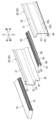
図2は、本実施形態に係る車両側部構造の左側の一部を示した斜視図である。図3は、本実施形態に係る車両側部構造の左側の一部を示した分解斜視図である。図4は、本実施形態に係る車両側部構造が適用された車両のロッカー20に衝撃荷重Fが入力された状態を模式的に示した断面図である。ロッカー10、20は、車幅方向の側方において車両前後方向に延在して車両の骨格構造の一部として機能されるものである。ここで、ロッカー10とロッカー20は、左右対称の構造であり実質的に同一の構成であるため、代表して詳細構成を左側のロッカー20を用いて説明することとし、ロッカー10についての詳細説明は省略する。図2から図4に示すように、ロッカー20は、ロッカーインナパネル30と、ロッカーアウタパネル40とが互いの開口を対向させた状態で重ね合わせて接合されることで筒状の内方空間22を構成している。
<Lockers 10, 20>
FIG. 2 is a perspective view showing a portion of the left side of the vehicle side structure according to the present embodiment. FIG. 3 is an exploded perspective view showing a portion of the left side of the vehicle side structure according to the present embodiment. FIG. 4 is a cross-sectional view schematically showing a state where an impact load F is input to the
ロッカーインナパネル30は、鋼板製であり、車幅方向の外方側が開口した断面ハット状で構成されている。ロッカーインナパネル30は、車幅方向に切った断面視で見て、上方側から下方側に向かって、上方フランジ面31、上端面32、側壁面33、下端面34、立設面35、下方フランジ面36を有した断面ハット状で構成されている。上方フランジ面31は、車両上下方向に延在した面であり、後述するロッカーアウタパネル40の上方フランジ面41と接合される部位である。上端面32は、上方フランジ面31の下端縁から屈曲して車両幅方向の内方側に延在する面である。側壁面33は、上端面32の内方縁から屈曲して車両上下方向の下方に向かって延在する面である。下端面34は、側壁面33の下端縁から屈曲して車両幅方向の外方側に延在する面である。立設面35は、下端面34の外方縁から屈曲して車両上下方向の下方に向かって延在する面である。下方フランジ面36は、立設面35から延長された面であり、後述するロッカーアウタパネル40の下方フランジ面46と接合される部位である。
The locker
ロッカーアウタパネル40は、鋼板製であり、車幅方向の内方側が開口した断面ハット状で構成されている。ロッカーアウタパネル40は、車幅方向に切った断面視で上方から下方に向かって、上方フランジ面41、上端面42、側壁面43、下端面44、下方フランジ面46を有した断面ハット状で構成されている。上方フランジ面41は、車両上下方向に延在した面であり、上述したロッカーインナパネル30の上方フランジ面31と接合される部位である。上端面42は、上方フランジ面41の下端縁から屈曲して車両幅方向の外方側に延在する面である。側壁面43は、上端面42の外方縁から屈曲して車両上下方向の下方に向かって延在する面である。下端面44は、側壁面43の下端縁から屈曲して車両幅方向の内方側に延在する面である。下方フランジ面46は、下端面44の内方縁から屈曲して車両上下方向の下方に向かって延在する面であり、上述したロッカーインナパネル30の下方フランジ面36と接合される部位である。
The rocker
ロッカー20は、ロッカーインナパネル30と、ロッカーアウタパネル40とが互いの開口を対向させた状態で重ね合わせる。そして、上方フランジ面31と上方フランジ面41をスポット溶接にて接合する。また下方フランジ面36と下方フランジ面46をスポット溶接にて接合する。こうしてロッカー20は、筒状の内方空間22を構成する。
In the
ここで、ロッカーインナパネル30の側壁面33に比べて、ロッカーアウタパネル40の側壁面43の方が長く設定されている。すなわち、ロッカーアウタパネル40の側壁面43の長さは、ロッカーインナパネル30における側壁面33と立設面35の両方の長さと略同じ長さである。よって、ロッカーインナパネル30の下端面34と、ロッカーアウタパネル40の下端面44の車両上下方向の位置関係を見ると、相対的にロッカーインナパネル30の下端面34の方が上方に位置し、ロッカーアウタパネル40の下端面44の方が下方に位置している。従って、ロッカー20の内方空間22は、ロッカー20の下面において車幅方向の外方側下面が内方側下面よりも相対的に下方に延長した段差形状とされることで延長空間24が構成されている。延長空間24内には、荷重伝達部材60を有している。
Here, the
<荷重伝達部材60>
荷重伝達部材60は、ロッカー20に沿って延在する長尺状であると共にロッカーインナパネル30又はロッカーアウタパネル40のいずれかと接合されることで閉断面部を構成する部材である。本実施形態における荷重伝達部材60は、ロッカーインナパネル30と接合されることで閉断面部を構成する。荷重伝達部材60は、上方接合面61、延在面62と、対向面64と、折返し面66と、下方接合面67を有しており、ロッカーインナパネル30と接合されて延長空間24内に閉断面部を構成する。
<
The
上方接合面61、延在面62と、対向面64と、折返し面66、下方接合面67は、車幅方向に切った断面視で見て、次のような構成である。上方接合面61は、ロッカーインナパネル30の下端面34とスポット溶接によって接合される面である。延在面62は、上方接合面61から延長され、ロッカーインナパネル30側からロッカーアウタパネル40側に向かって延在する面である。対向面64は、延在面62の外方縁から屈曲してロッカーアウタパネル40と対向する面である。折返し面66は、対向面64の下端縁から屈曲してロッカーインナパネル30側へ折り返される面である下方接合面67は、折返し面66から屈曲して、ロッカーインナパネル30の立設面35に面して、この立設面35とスポット溶接によって接合される面である。ここで、上方接合面61、下方接合面67は、ロッカーインナパネル30に対しスポット溶接で接合される「接合部」に相当する。また、荷重伝達部材60は、車幅方向に沿ったビード68が車両前後方向に間隔を隔てて長手方向全域に複数列が構成されている。ここで、ビード68が「第2のビード」に相当する。
The upper
ロッカーアウタパネル40には、対向面64を挟む上下位置に隣接した位置でロッカー20の内方空間22側に突出する上方ビード43a、下方ビード43bが車両前後方向に沿って設けられている。ここで、上方ビード43a、下方ビード43bは、対向面64よりも車幅方向の内方側まで突出していることから、荷重伝達部材60と上下方向において重なった位置関係で構成される。ここで、上方ビード43a、下方ビード43bは、対向面64を挟む上下位置に隣接した位置でロッカー20の内方空間22側に突出する「第1のビード」に相当する。
The locker
<衝撃吸収部材70>
衝撃吸収部材70は、ロッカー20と隣接することで車幅方向の外方側からの衝突エネルギーを吸収する機能を有する。具体的に衝撃吸収部材70は、ロッカー20の延長空間24とアルミニウムフレーム90の挟まれた位置に配設されている。衝撃吸収部材70は、合成樹脂製の箱型状で構成されている。衝撃吸収部材70は、車幅方向において中空の筒状体72が複数連続して隣接することで平面充填されたハニカム構造で構成される。本実施形態では、正六角形の中空の筒状体72が平面充填されたハニカム構造で構成される。
<Shock absorbing
The
<作用・効果>
図4は、本実施形態に係る車両側部構造が適用された車両のロッカー20に衝撃荷重Fが入力された状態を模式的に示した断面図である。ここで、車幅方向の外方側から及ぼされる衝撃荷重Fは、ロッカー20の側壁面43から下端面44を通じて衝撃吸収部材70の下方側に伝達される。また、衝撃荷重Fは、ロッカー20の側壁面43と荷重伝達部材60の対向面64が接触すると、延在面62、上方接合面61を通じて衝撃吸収部材70の上方側に伝達される。また、衝撃荷重Fは、ロッカー20の側壁面43と荷重伝達部材60の対向面64が接触すると、折返し面66、下方接合面67を通じて衝撃吸収部材70の中段側に伝達される。このように、ポール側突等の側面衝突の衝撃荷重Fは、ロッカー20の一部に局所的に集中することが考えられるが、本実施形態の車両側部構造であれば、衝撃吸収部材70全体に満遍なく荷重が伝達されるため、効率よく車幅方向の衝突エネルギーを吸収することができる。また、ロッカー20は、アルミニウム合金の押出材とは異なり鋼板製による簡素な構造によって骨格を構成できる。
<Action/Effect>
FIG. 4 is a cross-sectional view schematically showing a state where an impact load F is input to the
以上、本実施形態について説明したが、車両側部構造は、本実施形態に限定されず、その他各種の形態で実施することができる。図5は、本実施形態に係る車両側部構造の変形例が適用された車両のロッカー20に衝撃荷重Fが入力された状態を模式的に示した断面図である。なお、上述した実施形態と実質的に同一な構成については、各符号の数に100を加えた符号とし、各部の詳細な説明は省略することがある。図5に示すように、例えば、ロッカー120は、ロッカーインナパネル130とロッカーアウタパネル140のように、互いを接合するフランジの形態は種々適用できる。例えば、下方フランジ面136、146のように互いに近接する方向に屈曲して重ね合わせて接合する形態であってもよい。上方フランジ面131、141も同様に、種々の形態を適用できる。また、荷重伝達部材160のようにロッカーアウタパネル40と接合されることで閉断面部を構成する部材であってもよい。また、ロッカー120には、上方ビード43a、下方ビード43b(第1のビード)と同様の構成を設けてもよい。荷重伝達部材160には、ビード68(第2のビード)と同様の構成を設けてもよい。
Although the present embodiment has been described above, the vehicle side structure is not limited to this embodiment, and can be implemented in various other forms. FIG. 5 is a cross-sectional view schematically showing a state in which an impact load F is input to the
<各発明に対応する上記実施形態の作用効果>
なお、最後に上述の「課題を解決するための手段」における第1発明以降の各発明に対応する上記実施形態の作用効果を付記しておく。
<Operations and effects of the above embodiments corresponding to each invention>
Finally, the effects of the above-described embodiments corresponding to each of the inventions after the first invention in the above-mentioned "Means for Solving the Problems" will be added.
第1の発明によれば、車幅方向の側方において車両前後方向に延在した車両骨格構造の一部としてのロッカー20と、ロッカー20と隣接することで車幅方向の外方側からの衝突エネルギーを吸収する衝撃吸収部材70と、を有する車両側部構造である。ロッカー20は、車幅方向の外方側が開口した断面ハット状で構成された鋼板製のロッカーインナパネル30と、車幅方向の内方側が開口した断面ハット状で構成された鋼板製のロッカーアウタパネル40と、が互いの開口を対向させた状態で重ね合わせて接合されることで筒状の内方空間22を構成している。ロッカー20の内方空間22は、ロッカー20の下面において車幅方向の外方側下面が内方側下面よりも相対的に下方に延長した段差形状とされることで延長空間24が構成されている。この延長空間24内には、ロッカー20に沿って延在する長尺状であると共にロッカーインナパネル30又はロッカーアウタパネル40のいずれかと接合されることで閉断面部を構成する荷重伝達部材60を有している。荷重伝達部材60を通じて車幅方向の外方側からの衝撃荷重Fが、延長空間24に対し車幅方向の内方側に隣接される衝撃吸収部材70に伝達される。これにより、車幅方向の側方において車両前後方向に延在した車両骨格構造の一部としてのロッカー20において、アルミニウム合金の押出材とは異なる素材によって骨格を構成すると共に、車幅方向の衝突エネルギーを吸収する衝撃吸収部材70に対し効率よく衝撃荷重Fを伝達する構造とすることができる。
According to the first invention, the
第2の発明によれば、荷重伝達部材60は、ロッカーインナパネル30と接合されることで閉断面部を構成するため、延長空間24内の閉断面部の配設位置を設定しやすい。よって、衝撃吸収部材70に対し効率よく衝撃荷重Fを伝達する構造とすることができる。
According to the second invention, the
第3の発明によれば、荷重伝達部材60は、ロッカーインナパネル30の下端面34と接合されているため、衝撃荷重Fの及ぼされる方向に抗する位置で接合することになり効率的な構造とすることができる。
According to the third invention, since the
第4の発明によれば、荷重伝達部材60は、ロッカーインナパネル30側からロッカーアウタパネル40側に向かって延在する延在面62と、ロッカーアウタパネル40と対向する対向面64と、ロッカーインナパネル30側へ折り返される折返し面66によって、閉断面部を構成している。ロッカーアウタパネル40には、対向面64を挟む上下位置に隣接した位置でロッカー20の内方空間22側に突出する上方ビード43a、下方ビード43b(第1のビード)が車両前後方向に沿って設けられている。上方ビード43a、下方ビード43bは、荷重伝達部材60と上下方向において重なった位置関係で構成される。そのため、荷重伝達部材60の上下方向の倒れを抑制することができる。
According to the fourth invention, the
第5の発明によれば、荷重伝達部材60は、ロッカーアウタパネル40と接合されることで閉断面部を構成する。そのため、延長空間の形状によっては荷重伝達部材60をロッカーアウタパネル側と接合する態様とすることもでき、設計自由度の向上を図ることができる。
According to the fifth invention, the
第6の発明によれば、荷重伝達部材60は、車幅方向に沿ったビード68(第2のビード)が車両前後方向に間隔を隔てて複数列が構成されるため、車幅方向から及ぼされる衝撃荷重Fに対する剛性を向上させることができる。
According to the sixth invention, the
第7の発明によれば、荷重伝達部材60は、ロッカーインナパネル30またはロッカーアウタパネル40に対しスポット溶接で接合された上方接合面61、下方接合面67(接合部)を有するため、効率的に接合が可能とすることができる。
According to the seventh invention, the
第8の発明によれば、衝撃吸収部材70は、合成樹脂の中空の筒状体72が複数連続して隣接することで平面充填されたハニカム構造で構成されることで軽量化を図ることができる。
According to the eighth aspect of the invention, the
10 ロッカー
20 ロッカー
22 内方空間
24 延長空間
30 ロッカーインナパネル
31 上方フランジ面
32 上端面
33 側壁面
34 下端面
35 立設面
36 下方フランジ面
40 ロッカーアウタパネル
41 上方フランジ面
42 上端面
43 側壁面
44 下端面
46 下方フランジ面
43a 上方ビード(第1のビード)
43b 下方ビード(第1のビード)
60 荷重伝達部材
61 上方接合面(接合部)
62 延在面
64 対向面
66 折返し面
67 下方接合面(接合部)
68 ビード(第2のビード)
70 衝撃吸収部材
72 筒状体
80 電池パック
90 アルミニウムフレーム
120 ロッカー
122 内方空間
124 延長空間
130 ロッカーインナパネル
131 上方フランジ面
132 上端面
133 側壁面
134 下端面
135 立設面
136 下方フランジ面
140 ロッカーアウタパネル
141 上方フランジ面
142 上端面
143 側壁面
146 下方フランジ面
160 荷重伝達部材
161 上方接合面(接合部)
162 延在面
164 対向面
166 折返し面
167 下方接合面(接合部)
F 衝撃荷重
10
43b Lower bead (first bead)
60
62
68 bead (second bead)
70
162
F Impact load
Claims (6)
前記ロッカーは、車幅方向の外方側が開口した断面ハット状で構成された鋼板製のロッカーインナパネルと、車幅方向の内方側が開口した断面ハット状で構成された鋼板製のロッカーアウタパネルと、が互いの開口を対向させた状態で重ね合わせて接合されることで筒状の内方空間を構成しており、
前記ロッカーの内方空間は、前記ロッカーの下面において車幅方向の外方側下面が内方側下面よりも相対的に下方に延長した段差形状とされることで延長空間が構成されており、
前記延長空間内には、前記ロッカーに沿って延在する長尺状であると共に、前記ロッカーインナパネル側から前記ロッカーアウタパネル側に向かって延在する延在面と、前記ロッカーアウタパネルと対向する対向面と、前記ロッカーインナパネル側へ折り返される折返し面を有しており、前記ロッカーインナパネルと接合されることで閉断面部を構成する荷重伝達部材を有し、
前記ロッカーアウタパネルには、前記対向面を挟む上下位置に隣接した位置で前記ロッカーの内方空間側に突出する第1のビードが車両前後方向に沿って設けられており、
前記第1のビードは、前記荷重伝達部材と上下方向において重なった位置関係で構成されており、
前記荷重伝達部材を通じて車幅方向の外方側からの衝撃荷重が、前記延長空間に対し車幅方向の内方側に隣接される前記衝撃吸収部材に伝達される車両側部構造。 A locker as a part of the vehicle frame structure extending in the longitudinal direction of the vehicle on the side in the vehicle width direction; and a shock absorbing member that is adjacent to the locker and absorbs collision energy from the outer side in the vehicle width direction. A vehicle side structure comprising:
The locker includes a locker inner panel made of a steel plate and having a hat-shaped cross section with an open outward side in the vehicle width direction, and a locker outer panel made of a steel plate having a hat-like cross section with an open inner side in the vehicle width direction. , are stacked and joined together with their openings facing each other to form a cylindrical inner space.
The inner space of the locker is configured as an extension space by forming a step shape in which the outer lower surface in the vehicle width direction extends relatively downwardly than the inner lower surface on the lower surface of the locker,
The extension space includes an elongated surface extending along the locker and extending from the locker inner panel side toward the locker outer panel side, and an opposing surface facing the locker outer panel. and a folded surface that is folded back toward the locker inner panel, and has a load transmission member that forms a closed cross-section when joined to the locker inner panel ;
The locker outer panel is provided with a first bead extending in the longitudinal direction of the vehicle at a position adjacent to the upper and lower positions sandwiching the opposing surface and protruding toward the inner space side of the locker,
The first bead is configured in a vertically overlapping positional relationship with the load transmission member,
A vehicle side structure in which an impact load from an outer side in a vehicle width direction is transmitted to the impact absorbing member adjacent to an inner side in a vehicle width direction with respect to the extension space through the load transmission member.
前記荷重伝達部材は、前記ロッカーインナパネルの下端面と接合されている車両側部構造。 The vehicle side structure according to claim 1 ,
The load transmission member is a vehicle side structure joined to a lower end surface of the locker inner panel.
前記ロッカーは、車幅方向の外方側が開口した断面ハット状で構成された鋼板製のロッカーインナパネルと、車幅方向の内方側が開口した断面ハット状で構成された鋼板製のロッカーアウタパネルと、が互いの開口を対向させた状態で重ね合わせて接合されることで筒状の内方空間を構成しており、
前記ロッカーの内方空間は、前記ロッカーの下面において車幅方向の外方側下面が内方側下面よりも相対的に下方に延長した段差形状とされることで延長空間が構成されており、
前記延長空間内には、前記ロッカーに沿って延在する長尺状であると共に前記ロッカーアウタパネルと接合されることで閉断面部を構成する荷重伝達部材を有し、
前記荷重伝達部材を通じて車幅方向の外方側からの衝撃荷重が、前記延長空間に対し車幅方向の内方側に隣接される前記衝撃吸収部材に伝達される車両側部構造。 A locker as a part of the vehicle frame structure extending in the longitudinal direction of the vehicle on the side in the vehicle width direction; and a shock absorbing member that is adjacent to the locker and absorbs collision energy from the outer side in the vehicle width direction. A vehicle side structure comprising:
The locker includes a locker inner panel made of a steel plate and having a hat-shaped cross section with an open outward side in the vehicle width direction, and a locker outer panel made of a steel plate having a hat-like cross section with an open inner side in the vehicle width direction. , are stacked and joined together with their openings facing each other to form a cylindrical inner space.
The inner space of the locker is configured as an extension space by forming a step shape in which the outer lower surface in the vehicle width direction extends relatively downwardly than the inner lower surface on the lower surface of the locker,
The extension space includes a load transmission member that is elongated and extends along the locker and forms a closed cross-section by being joined to the locker outer panel ;
A vehicle side structure in which an impact load from an outer side in a vehicle width direction is transmitted to the impact absorbing member adjacent to an inner side in a vehicle width direction with respect to the extension space through the load transmission member.
前記荷重伝達部材は、車幅方向に沿った第2のビードが車両前後方向に間隔を隔てて複数列が構成される車両側部構造。 The vehicle side structure according to any one of claims 1 to 3 ,
The load transmission member has a vehicle side structure in which a plurality of rows of second beads extending in the vehicle width direction are spaced apart from each other in the vehicle longitudinal direction.
前記荷重伝達部材は、前記ロッカーインナパネルまたは前記ロッカーアウタパネルに対しスポット溶接で接合された接合部を有する車両側部構造。 The vehicle side structure according to any one of claims 1 to 4 ,
The load transmission member is a vehicle side structure having a joint portion joined to the rocker inner panel or the rocker outer panel by spot welding.
前記ロッカーは、車幅方向の外方側が開口した断面ハット状で構成された鋼板製のロッカーインナパネルと、車幅方向の内方側が開口した断面ハット状で構成された鋼板製のロッカーアウタパネルと、が互いの開口を対向させた状態で重ね合わせて接合されることで筒状の内方空間を構成しており、
前記ロッカーの内方空間は、前記ロッカーの下面において車幅方向の外方側下面が内方側下面よりも相対的に下方に延長した段差形状とされることで延長空間が構成されており、
前記延長空間内には、前記ロッカーに沿って延在する長尺状であると共に前記ロッカーインナパネル又は前記ロッカーアウタパネルのいずれかと接合されることで閉断面部を構成する荷重伝達部材を有し、
前記衝撃吸収部材は、合成樹脂の中空の筒状体が複数連続して隣接することで平面充填されたハニカム構造で構成されており、
前記荷重伝達部材を通じて車幅方向の外方側からの衝撃荷重が、前記延長空間に対し車幅方向の内方側に隣接される前記衝撃吸収部材に伝達される車両側部構造。
A locker as a part of the vehicle frame structure extending in the longitudinal direction of the vehicle on the side in the vehicle width direction; and a shock absorbing member that is adjacent to the locker and absorbs collision energy from the outer side in the vehicle width direction. A vehicle side structure comprising:
The locker includes a locker inner panel made of a steel plate and having a hat-shaped cross section with an open outward side in the vehicle width direction, and a locker outer panel made of a steel plate having a hat-like cross section with an open inner side in the vehicle width direction. , are stacked and joined together with their openings facing each other to form a cylindrical inner space.
The inner space of the locker is configured as an extension space by forming a step shape in which the outer lower surface in the vehicle width direction extends relatively downwardly than the inner lower surface on the lower surface of the locker,
In the extension space, there is a load transmission member that is elongated and extends along the locker and forms a closed cross-section by being joined to either the locker inner panel or the rocker outer panel;
The shock absorbing member has a honeycomb structure in which a plurality of hollow cylindrical bodies of synthetic resin are filled in a plane and are adjacent to each other,
A vehicle side structure in which an impact load from an outer side in a vehicle width direction is transmitted to the impact absorbing member adjacent to an inner side in a vehicle width direction with respect to the extension space through the load transmission member.
Priority Applications (5)
| Application Number | Priority Date | Filing Date | Title |
|---|---|---|---|
| JP2021015597A JP7427618B2 (en) | 2021-02-03 | 2021-02-03 | Vehicle side structure |
| US18/259,835 US20240083510A1 (en) | 2021-02-03 | 2022-02-02 | Vehicular side structure |
| EP22749744.3A EP4257458A1 (en) | 2021-02-03 | 2022-02-02 | Vehicular side structure |
| PCT/JP2022/004064 WO2022168873A1 (en) | 2021-02-03 | 2022-02-02 | Vehicular side structure |
| CN202280008636.3A CN116723973A (en) | 2021-02-03 | 2022-02-02 | Vehicle side structure |
Applications Claiming Priority (1)
| Application Number | Priority Date | Filing Date | Title |
|---|---|---|---|
| JP2021015597A JP7427618B2 (en) | 2021-02-03 | 2021-02-03 | Vehicle side structure |
Publications (2)
| Publication Number | Publication Date |
|---|---|
| JP2022118832A JP2022118832A (en) | 2022-08-16 |
| JP7427618B2 true JP7427618B2 (en) | 2024-02-05 |
Family
ID=82741460
Family Applications (1)
| Application Number | Title | Priority Date | Filing Date |
|---|---|---|---|
| JP2021015597A Active JP7427618B2 (en) | 2021-02-03 | 2021-02-03 | Vehicle side structure |
Country Status (5)
| Country | Link |
|---|---|
| US (1) | US20240083510A1 (en) |
| EP (1) | EP4257458A1 (en) |
| JP (1) | JP7427618B2 (en) |
| CN (1) | CN116723973A (en) |
| WO (1) | WO2022168873A1 (en) |
Citations (2)
| Publication number | Priority date | Publication date | Assignee | Title |
|---|---|---|---|---|
| JP2019137354A (en) | 2018-02-15 | 2019-08-22 | 本田技研工業株式会社 | Vehicle body structure |
| JP2019166850A (en) | 2018-03-22 | 2019-10-03 | 株式会社Subaru | Vehicle body structure dealing with side surface impact |
Family Cites Families (2)
| Publication number | Priority date | Publication date | Assignee | Title |
|---|---|---|---|---|
| JP6806115B2 (en) | 2018-08-22 | 2021-01-06 | トヨタ自動車株式会社 | Vehicle side structure |
| JP7413844B2 (en) * | 2020-03-03 | 2024-01-16 | トヨタ自動車株式会社 | Vehicle undercarriage structure |
-
2021
- 2021-02-03 JP JP2021015597A patent/JP7427618B2/en active Active
-
2022
- 2022-02-02 EP EP22749744.3A patent/EP4257458A1/en active Pending
- 2022-02-02 US US18/259,835 patent/US20240083510A1/en active Pending
- 2022-02-02 WO PCT/JP2022/004064 patent/WO2022168873A1/en active Application Filing
- 2022-02-02 CN CN202280008636.3A patent/CN116723973A/en active Pending
Patent Citations (2)
| Publication number | Priority date | Publication date | Assignee | Title |
|---|---|---|---|---|
| JP2019137354A (en) | 2018-02-15 | 2019-08-22 | 本田技研工業株式会社 | Vehicle body structure |
| JP2019166850A (en) | 2018-03-22 | 2019-10-03 | 株式会社Subaru | Vehicle body structure dealing with side surface impact |
Also Published As
| Publication number | Publication date |
|---|---|
| EP4257458A1 (en) | 2023-10-11 |
| CN116723973A (en) | 2023-09-08 |
| US20240083510A1 (en) | 2024-03-14 |
| JP2022118832A (en) | 2022-08-16 |
| WO2022168873A1 (en) | 2022-08-11 |
Similar Documents
| Publication | Publication Date | Title |
|---|---|---|
| JP7405299B2 (en) | Battery mounting structure | |
| JP6866784B2 (en) | Body undercarriage | |
| US11208152B2 (en) | Vehicle body side section structure | |
| CN109383257B (en) | Vehicle side structure | |
| JP6512163B2 (en) | Vehicle battery mounting structure | |
| JP2017196952A (en) | Battery mounting structure of vehicle | |
| US8567855B2 (en) | Bumper mounting plate for double channel front rails | |
| US9061712B2 (en) | Understructure for a vehicle | |
| JP5683708B2 (en) | Car body rear structure | |
| JP4386131B2 (en) | Electric car | |
| US20180312199A1 (en) | Vehicle lower section structure | |
| JP5708567B2 (en) | Battery mounting structure for vehicles | |
| KR101565981B1 (en) | Floor panel assembly for electric vehicle | |
| KR101565980B1 (en) | Floor panel assembly for electric vehicle | |
| JP7231572B2 (en) | Underbody structure | |
| JP2017197093A (en) | Battery mounting structure of vehicle | |
| US20210094626A1 (en) | Body of electric vehicle | |
| CN114228833B (en) | Energy absorption structure for small offset collision of automobile and automobile | |
| JP7211986B2 (en) | Underbody structure | |
| JP7239503B2 (en) | Underbody structure | |
| JP6183203B2 (en) | Body structure | |
| JP7366342B2 (en) | Lower body structure of electric vehicle | |
| JP2020196432A (en) | Lower part vehicle body structure of electric vehicle | |
| JP7427618B2 (en) | Vehicle side structure | |
| JP2017185948A (en) | Battery mounting structure for vehicle |
Legal Events
| Date | Code | Title | Description |
|---|---|---|---|
| A621 | Written request for application examination |
Free format text: JAPANESE INTERMEDIATE CODE: A621 Effective date: 20230508 |
|
| A131 | Notification of reasons for refusal |
Free format text: JAPANESE INTERMEDIATE CODE: A131 Effective date: 20231205 |
|
| A521 | Request for written amendment filed |
Free format text: JAPANESE INTERMEDIATE CODE: A523 Effective date: 20231215 |
|
| TRDD | Decision of grant or rejection written | ||
| A01 | Written decision to grant a patent or to grant a registration (utility model) |
Free format text: JAPANESE INTERMEDIATE CODE: A01 Effective date: 20240109 |
|
| A61 | First payment of annual fees (during grant procedure) |
Free format text: JAPANESE INTERMEDIATE CODE: A61 Effective date: 20240124 |
|
| R150 | Certificate of patent or registration of utility model |
Ref document number: 7427618 Country of ref document: JP Free format text: JAPANESE INTERMEDIATE CODE: R150 |