JP6183203B2 - Body structure - Google Patents
Body structure Download PDFInfo
- Publication number
- JP6183203B2 JP6183203B2 JP2013262725A JP2013262725A JP6183203B2 JP 6183203 B2 JP6183203 B2 JP 6183203B2 JP 2013262725 A JP2013262725 A JP 2013262725A JP 2013262725 A JP2013262725 A JP 2013262725A JP 6183203 B2 JP6183203 B2 JP 6183203B2
- Authority
- JP
- Japan
- Prior art keywords
- vehicle
- vehicle body
- body structure
- front side
- additional
- Prior art date
- Legal status (The legal status is an assumption and is not a legal conclusion. Google has not performed a legal analysis and makes no representation as to the accuracy of the status listed.)
- Active
Links
Images


Landscapes
- Body Structure For Vehicles (AREA)
Description
本発明は、複数の車種に対応する車体構造に関するものである。 The present invention relates to a vehicle body structure corresponding to a plurality of vehicle types.
自動車の製造コストを削減する対策として、部品の共用化が考えられている。中でも、複数の車種で車体構成部品の共用化を図ることによって製造コストを削減することが考えられている。このように共用化された車体構成部品のまとまり(プラットフォーム)は、それぞれの車種で必要とされる強度や剛性を満たすようにしながら、可能な限り多くの車体構成部品を含むように構成されることが望まれている。 As a measure to reduce the manufacturing cost of automobiles, sharing of parts is considered. In particular, it is considered to reduce the manufacturing cost by sharing the vehicle body components among a plurality of vehicle types. A group of vehicle body components shared in this way (platform) should be configured to include as many vehicle body components as possible while satisfying the strength and rigidity required for each vehicle type. Is desired.
特許文献1には、トラックのフレーム構造を4つのユニットに分割し、必要に応じてユニット毎に設計を変更することが記載されている。このようなトラックのフレーム構造は、モノコックボディを有する自動車に直接適用することはできないが、4つのユニットのうち例えば1つのユニットのみを設計変更することによって他車種で必要とされる強度等を満たすことができれば、他の3つのユニットについては他車種と共用化することができると考えられる。
また、特許文献2には、セダン,SUV(Sport Utility Vehicle)及び電気自動車を例とする複数の車種で共用化を図ったフロアパネルが記載されている。特に電気自動車には比較的重量の大きいバッテリが搭載されるため他車種に比べて高い強度や剛性が必要とされるが、このフロアパネルは電気自動車に必要とされる強度や剛性を満たし且つ複数の車種で共用可能であるものとされている。
上述したように、セダン,SUV及び電気自動車を例とする複数の車種では、車重や車体が支持する対象物が異なるため、必要とされる強度や剛性も異なる。このような複数の車種で共用可能なプラットフォームを構成する場合、それぞれの車種で必要とされる強度や剛性を満たすようにするには最も車重の大きい電気自動車に適合させたプラットフォームを構成すればよいが、この場合、他の車種には過剰な強度や剛性を持たせてしまい、車体の製造コスト及び重量を増加させてしまうため、コスト削減ができないだけでなく、車両の性能低下も招き適用できない。 As described above, in a plurality of vehicle types such as sedans, SUVs, and electric vehicles, since the vehicle weight and the object supported by the vehicle body are different, the required strength and rigidity are also different. When configuring a platform that can be shared by multiple vehicle types, if you want to meet the strength and rigidity required by each vehicle type, configure a platform that is suitable for the electric vehicle with the largest vehicle weight. However, in this case, other vehicles are given excessive strength and rigidity, which increases the manufacturing cost and weight of the car body. Can not.
本発明は、このような課題に鑑み創案されたものであり、車種に応じて必要な強度や剛性を確保することができるようにした車体構造を提供することを目的とする。 The present invention has been made in view of such a problem, and an object of the present invention is to provide a vehicle body structure that can ensure necessary strength and rigidity in accordance with a vehicle type.
(1)上記目的を達成するために、本発明の車体構造は、複数の車種に対応する車体構造であって、左右一対のフロントサイドメンバと、前記一対のフロントサイドメンバに各端部を結合されたフロントクロスメンバと、対応する前記フロントサイドメンバの外方に、フロントフロアサイドブレースを介して結合された左右一対のサイドシルと、対応する前記サイドシルに前端部を結合された左右一対のリヤフロアサイドメンバと、前記一対のフロントサイドメンバの後部に結合されると共に、前記一対のリヤフロアサイドメンバに各端部を結合された第1リヤクロスメンバと、前記第1リヤクロスメンバの後方に配置され、前記一対のリヤフロアサイドメンバに各端部を結合された第2リヤクロスメンバと、を備え、前記一対のフロントサイドメンバには、車体内方に延設されたフロントサイドメンバセンタが設けられ、それぞれの前記フロントサイドメンバセンタ及び前記第1リヤクロスメンバには、車長方向に配設される第1の追加部材を結合可能な第1の結合点がそれぞれ形成され、前記フロントクロスメンバには、車長方向に配設される第2の追加部材を結合可能な第2の結合点が形成され、前記一対のフロントサイドメンバの各対向箇所には、車幅方向に配設される第3の追加部材を結合可能な第3の結合点がそれぞれ形成されていることを特徴としている。 (1) In order to achieve the above object, the vehicle body structure of the present invention is a vehicle body structure corresponding to a plurality of vehicle types, and a pair of left and right front side members and each end portion are coupled to the pair of front side members. Front cross members, a pair of left and right side sills coupled to the outside of the corresponding front side members via front floor side braces, and a pair of left and right rear floor sides coupled to the corresponding side sills at the front end. A first rear cross member that is coupled to a rear portion of the pair of front side members and a pair of rear floor side members, and a rear end of the first rear cross member; A second rear cross member having ends connected to the pair of rear floor side members, and the pair of front supports. The front member is provided with a front side member center extending inward of the vehicle body, and each of the front side member center and the first rear cross member has a first additional member disposed in the vehicle length direction. Are formed, and the front cross member is formed with a second coupling point capable of coupling a second additional member disposed in the vehicle length direction, A third coupling point capable of coupling a third additional member disposed in the vehicle width direction is formed at each of the opposing portions of the front side member.
(2)前記第1の追加部材及び前記第2の追加部材は、重量車種に適合させるための補強用構造部材であることが好ましい。
(3)前記第1の追加部材及び前記第3の追加部材は、電気自動車用バッテリケースの井桁状骨格構造であることが好ましい。
(2) Preferably, the first additional member and the second additional member are reinforcing structural members for adapting to a heavy vehicle type.
(3) It is preferable that the first additional member and the third additional member have a grid-like skeleton structure of a battery case for an electric vehicle.
(4)この場合、前記第2の追加部材は、重量車種に適合させるための補強用構造部材であることが好ましい。
(5)前記何れかの結合点には、対応する追加部材をボルトによって締結するための締結用部材が適用されていることが好ましい。
(4) In this case, the second additional member is preferably a reinforcing structural member for adapting to a heavy vehicle type.
(5) It is preferable that a fastening member for fastening a corresponding additional member with a bolt is applied to any of the coupling points.
本発明の車体構造によれば、第1,第2及び第3の追加部材をそれぞれ結合可能な第1,第2及び第3の結合点が形成されているため、車種に応じて第1,第2及び第3の追加部材を適宜結合することによって、複数の車種それぞれに応じた強度や剛性を確保することができる。
したがって、本発明の車体構造によれば、複数の車種で共用可能でありながら、適用される車種に所望の強度や剛性を持たせることができるため、車体の強度や剛性が過剰になり製造コスト及び重量が増加することを抑制することができる。
According to the vehicle body structure of the present invention, the first, second, and third coupling points that can couple the first, second, and third additional members, respectively, are formed. By appropriately combining the second and third additional members, it is possible to ensure strength and rigidity corresponding to each of a plurality of vehicle types.
Therefore, according to the vehicle body structure of the present invention, it is possible to give a desired strength and rigidity to an applied vehicle type while being shared by a plurality of vehicle types. In addition, an increase in weight can be suppressed.
以下、図面を参照して、本発明の実施の形態について説明する。なお、以下の説明における前後方向及び左右方向は、車両の前後方向及び左右方向に対応している。さらに、重力の方向を下方とし、その逆を上方とする。
また、以下の第1〜3実施形態は何れも共通(同一)のプラットフォームを有する車体構造を用いているが、適用車種がそれぞれ異なっている。以下、順に説明するが、第1実施形態は、そのプラットフォームの構造自体を説明するもので、比較的車高が低く車重が小さいセダン等の軽量車種に適用する場合には、追加部材を用いずにこのプラットフォームのみで車体構造を構成する。
Embodiments of the present invention will be described below with reference to the drawings. In the following description, the front-rear direction and the left-right direction correspond to the front-rear direction and the left-right direction of the vehicle. Furthermore, let the direction of gravity be the downward direction, and vice versa.
Moreover, although the following 1st-3rd embodiment uses the vehicle body structure which has a common (same) platform, all applicable vehicle models differ. Hereinafter, the first embodiment will be described in order, but the first embodiment describes the structure of the platform itself. When applied to a light vehicle such as a sedan having a relatively low vehicle height and a low vehicle weight, an additional member is used. Without using this platform, the vehicle body structure is constructed.
第2実施形態は、第1実施形態のプラットフォームを比較的車高が高く車重が大きいSUV等の重量車種に適用する場合のもので、補強用構造部材である第1及び第2の追加部材を第1実施形態のプラットフォームに結合して車体構造を構成する。
第3実施形態は、第1実施形態のプラットフォームを電気自動車の一つであるハイブリッド電気自動車に適用する場合のもので、電気自動車用バッテリケースの井桁状骨格構造である第1及び第3の追加部材及び補強用構造部材である第2の追加部材を第1実施形態のプラットフォームに結合して車体構造を構成する。
また、各実施形態に係るプラットフォームは、モノコックボディの車体構造の主要素であり、フレーム構造のフレームと区別するためにサブフレームとも呼ぶ。
The second embodiment is a case where the platform of the first embodiment is applied to a heavy vehicle such as an SUV having a relatively high vehicle height and a large vehicle weight, and the first and second additional members which are structural members for reinforcement. Is combined with the platform of the first embodiment to constitute a vehicle body structure.
The third embodiment is a case where the platform of the first embodiment is applied to a hybrid electric vehicle that is one of the electric vehicles, and the first and third additions that are a grid structure of a battery case for an electric vehicle. The vehicle body structure is configured by coupling the member and the second additional member, which is a structural member for reinforcement, to the platform of the first embodiment.
In addition, the platform according to each embodiment is a main element of the body structure of the monocoque body, and is also referred to as a subframe in order to distinguish from the frame of the frame structure.
<第1実施形態>
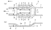
図1は、本実施形態に係る車体構造を示す模式的な図であり、図1(a)は平面図,図1(b)は側面図である。また、図2は、本実施形態に係る結合点を示す図1(a)のA−A矢視断面図である。
<First Embodiment>
1A and 1B are schematic views showing a vehicle body structure according to this embodiment. FIG. 1A is a plan view and FIG. 1B is a side view. FIG. 2 is a cross-sectional view taken along the line AA in FIG. 1A showing the connection point according to the present embodiment.
[1.基本的な構成]
[1−1.全体構成]
まず、図1を参照して、本実施形態に係る車体構造の全体構成を説明する。
図1に示すプラットフォーム9は、モノコックボディを有する複数の車種で車体構造に共用可能なサブフレームを形成している。このプラットフォーム9は、セダン等の比較的車重の小さい軽量車種の車体構造100にそのまま適用される。
[1. Basic configuration]
[1-1. overall structure]
First, the overall configuration of the vehicle body structure according to the present embodiment will be described with reference to FIG.
The
図1に示すように、プラットフォーム9は、車長方向(前後方向)に延びる部材として、フロントサイドメンバ1,サイドシル5及びリヤフロアサイドメンバ7を何れも左右一対ずつ備えている。また、プラットフォーム9は、車幅方向(左右方向)に延びる部材として、フロントクロスメンバ2,フロントフロアサイドブレース4,第1リヤクロスメンバ6及び第2リヤクロスメンバ8を備えている。なお、図1(b)に示す側面図では、サイドシル5及びフロントフロアサイドブレース4を省略している。
As shown in FIG. 1, the
上述した各部材は、自身の横断面(各部材の長手方向に垂直な平面で切断した面)あるいは接合するフロアパネル等と合体した横断面が矩形状の閉断面形状を形成するように、例えば鋼板がプレス加工されたものである。また、各部材の板厚は、軽量車種の車体構造100に要求される強度や剛性を満たすように、適宜の大きさに設定されている。
Each of the above-described members has a rectangular closed cross-sectional shape, for example, the cross-section of its own (cross-section cut by a plane perpendicular to the longitudinal direction of each member) or a cross-section combined with a floor panel to be joined, A steel plate is pressed. Further, the plate thickness of each member is set to an appropriate size so as to satisfy the strength and rigidity required for the
[1−2.フロントサイドメンバ]
左右一対のフロントサイドメンバ1,1は、軽量車種の車体構造100の前側部及び中央部に亘って、車幅方向に互いに離隔して配設されている。各フロントサイドメンバ1は、前方から順に、前方水平部1a,傾斜部1b,後方水平部1cを有している。
[1-2. Front side member]
The pair of left and right
前方水平部1aは、車長方向に沿って略水平に延設された部位である。傾斜部1bは、前方水平部1aの後端で屈曲され後方且つ下方に向かって傾斜した部位である。後方水平部1cは、傾斜部1bの後端で屈曲され車長方向に沿って略水平に延設された部位である。後方水平部1cは、軽量車種の車体構造100の車室下部空間101に位置し、その後部が後述する第1リヤクロスメンバ6に結合されている。
The front
なお、各フロントサイドメンバ1の前端部には、車幅方向に延在するフロントエンドクロスメンバ及びフロントバンパ(何れも図示略)が取り付けられる。また、ここではフロントサイドメンバ1が1部材で形成されるものとしているが、フロントサイドメンバ1は、例えば上述の前方水平部1a,傾斜部1b及び後方水平部1cがそれぞれ別の部材で形成され、これらの部材が結合されることにより構成されてもよい。
A front end cross member and a front bumper (both not shown) extending in the vehicle width direction are attached to the front end portion of each
[1−3.フロントクロスメンバ]
図1(b)に示すように、フロントサイドメンバ1の前方水平部1aの後端付近には、フロントクロスメンバ2のアーム部2aの上端部が下方から結合されている。また、フロントサイドメンバ1の傾斜部1bの後端付近には、フロントクロスメンバ2の基部2bの後端部が結合されている。フロントクロスメンバ2の基部2bは、一対のフロントサイドメンバ1,1の間に架設されており、基部2bの前側部分から上方のフロントサイドメンバ1,1に向かって左右一対のアーム部2a,2aがそれぞれ延設されている。
[1-3. Front cross member]
As shown in FIG. 1 (b), the upper end portion of the
[1−4.サイドシル]
左右一対のフロントサイドメンバ1,1の各後方水平部1cの外方(車体外側)には、左右一対のサイドシル5,5がそれぞれフロントサイドメンバ1の後方水平部1cと等しい高さで略水平に配設されている。各サイドシル5は、対応するフロントサイドメンバ1と車幅方向に離隔して配置され、これらの間には車幅方向に向いた複数のフロントフロアサイドブレース4が各フロントサイドメンバ1の後方水平部1c及び各サイドシル5と等しい高さで略水平に架設されている。換言すると、各サイドシル5は、フロントフロアサイドブレース4を介して対応するフロントサイドメンバ1に結合されている。
[1-4. Side sill]
The pair of left and
ここに示す例では、各サイドシル5に対して3本(前方から順に4A,4B,4Cと符号を付す。)のフロントフロアサイドブレース4が車長方向に互いに離隔して配設されている。これら3本のうち、最も前方に位置するフロントフロアサイドブレース4Aの車長方向位置はサイドシル5の前端部に対応している。
In the example shown here, three front floor side braces 4 (
また、これより後方のフロントフロアサイドブレース4B,4Cの車長方向位置は、これらの上面に配設されるフロアパネルを介して後に車幅方向に延設されるフロントシートクロスメンバ10A,10B(図1(b)参照)の車長方向位置にそれぞれ対応している。なお、フロントシートクロスメンバ10A,10Bは、下方に向けて開放されたハット型断面形状を有する補強部材であり、図示しないフロアパネルと相まって閉断面を形成する。また、フロントフロアサイドブレース4の本数は上記のものに限定されない。
The positions of the front floor side braces 4B and 4C in the rear of the vehicle in the vehicle length direction are the front
[1−5.リヤフロアサイドメンバ]
一対のサイドシル5,5の後部には、一対のリヤフロアサイドメンバ7,7が車幅方向に互いに離隔して配設されている。各リヤフロアサイドメンバ7は、軽量車種の車体構造100の後方側に位置し、前方から順に、傾斜部7a,水平部7bを有している。
傾斜部7aは、後方に向かって車体中心側且つ上方に傾斜した部位であり、前端部が対応するサイドシル5の上面に結合されている。水平部7bは、傾斜部7aの後端で屈曲され車長方向に沿って略水平に延設された部位である。
[1-5. Rear floor side member]
A pair of rear
The
[1−6.第1リヤクロスメンバ]
一対のリヤフロアサイドメンバ7,7の間には、第1リヤクロスメンバ6が架設されている。第1リヤクロスメンバ6は、左右端部が各リヤフロアサイドメンバ7の前端部に結合されていると共に、各フロントサイドメンバ1の後端部上面にも結合されている。
[1-6. First rear cross member]
A first
[1−7.第2リヤクロスメンバ]
第1リヤクロスメンバ6から後方に一定距離だけ離隔した位置には、第2リヤクロスメンバ8が配設されている。第2リヤクロスメンバ8の左右端部は、各リヤフロアサイドメンバ7の水平部7bに結合されている。
第1リヤクロスメンバ6,第2リヤクロスメンバ8及び一対のリヤフロアサイドメンバ7,7によって囲まれた空間内には、燃料タンク用空間12が設けられている。燃料タンク用空間12には、軽量車種の車体構造100に後付けされるエンジン(図示略)用の燃料を貯留するための燃料タンク(図示略)が配設される。
[1-7. Second rear cross member]
A second
A
[2.特徴的な構成]
[2−1.フロントサイドメンバセンタ]
次に、プラットフォーム9の特徴的な構成について説明する。
まず、上記に説明したフロントサイドメンバ1に設けられているフロントサイドメンバセンタ11について説明する。
[2. Characteristic configuration]
[2-1. Front side member center]
Next, a characteristic configuration of the
First, the front
図1(a)に示すように、各フロントサイドメンバ1には、車体内方に延設されたフロントサイドメンバセンタ11が設けられている。各フロントサイドメンバセンタ11は、前端部がフロントサイドメンバ1の傾斜部1bの前方部分に接合され、傾斜部1bの後方部分と側面視で重なり合うように、車体内方かつ後方に向かって延設されている。
各フロントサイドメンバセンタ11の後端部11aは、サイドシル5の前端部よりも後方に配置され、車長方向に沿って後方に向けられている。各後端部11aには、後述する追加部材41を結合可能な結合点21,21が形成されている。
As shown in FIG. 1A, each
The
フロントサイドメンバセンタ11は、プラットフォーム9を構成する上述した他部材と同様に、図示しないフロアパネルを下方から支持する。なお、ここではフロントサイドメンバセンタ11がフロントサイドメンバ1に接合されるものとしているが、フロントサイドメンバセンタ11は、フロントサイドメンバ1に例えばボルト及びナットなどで締結されてもよい。
The front
[2−2.結合点]
次に、プラットフォーム9に形成される結合点について説明する。結合点は、プラットフォーム9において、追加部材を結合可能な構造を有する箇所である。
図1では、各結合点を符号「×」で模式的に示している。図1に示すように、それぞれのフロントサイドメンバセンタ11,11の後端部11a,11a及び第1リヤクロスメンバ6には、車長方向に配設される追加部材(第1の追加部材)41,44(図3及び図4参照)を結合可能な結合点(第1の結合点)21がそれぞれ形成されている。
[2-2. Join point]
Next, connection points formed on the
In FIG. 1, each coupling point is schematically indicated by a symbol “x”. As shown in FIG. 1, each of the front side member centers 11, 11 has an additional member (first additional member) disposed in the vehicle length direction at the
また、フロントクロスメンバ2には、車長方向に配設される追加部材(第2の追加部材)42(例えば図3参照)を結合可能な結合点(第2の結合点)22が形成されている。さらに、一対のフロントサイドメンバ1,1の後方水平部1c,1cの各対向箇所には、側面視でフロントフロアサイドブレースと重なる(ラップ)位置の車幅方向に配設される追加部材(第3の追加部材)43(図4参照)を結合可能な結合点(第3の結合点)23がそれぞれ形成されている。
Further, the
各結合点21,22,23には、適用される結合方法に応じて適宜の構造が形成される。図2に示すように、ここでは結合点22において締結による結合が想定されており、追加部材42をボルト25によって締結するための締結用部材24が適用されている。
なお、図2は結合点22に追加部材42が結合された状態を示しているが、軽量車種の車体構造100には、結合点22に追加部材42が結合されていないプラットフォーム9が適用されている。
An appropriate structure is formed at each of the coupling points 21, 22, and 23 according to the applied coupling method. As shown in FIG. 2, here, coupling by fastening is assumed at the
FIG. 2 shows a state in which the
締結用部材24は、例えば鋼板を折り曲げ加工したものであり、略コの字状の横断面形状を有している。締結用部材24は、互いに平行に延びる上壁部24b及び下壁部24cと、これらの各一端部を接続し、これらと垂直に延びる側壁部24dとを有している。上壁部24b及び下壁部24cは、追加部材42の高さ方向の寸法に対応する距離だけ互いに離隔しており、それぞれに締結用のボルト25が挿通される孔部24aが穿設されている。
The
側壁部24bは、部材外側面(図2中右側の面)がフロントクロスメンバ2のアーム部2aに対して前方(図2中左側)からスポット溶接等により接合されている。つまり、締結用部材24は、結合点22の一部として予めプラットフォーム9に取り付けられているものであり、追加部材42を必要に応じて結合可能にしている。
なお、追加部材42は、例えば、横断面(車長方向に垂直な平面で切断した面)形状が略矩形の閉断面を形成するように鋼板を加工したものである。追加部材42の一端部には、ボルト25が挿通される孔部42aが穿設されている。
The
For example, the
結合点22に追加部材42を結合する場合、まず、締結用部材24の側壁部24dの部材内側面(図2中左側の面)に対して追加部材42の一端部を当接させ、追加部材42を締結用部材24の上壁部24b及び下壁部24cで上下方向から挟持した状態で、ボルト25を各孔部24a,42aに上方から挿通し、下方でナット26と締結する。これによって、プラットフォーム9の結合点22に追加部材42が結合される。
When the
なお、他の結合点21,23にも図2に示す結合点22と同様の構造を形成することができるが、これらの結合点21,22,23は上述したものに限らず、適宜の構造に形成することができる。例えば、上述したボルト25及びナット26の代わりに溶接やリベット等を使用してもよい。また、締結用部材24を適用せず、例えばフロントクロスメンバ2のアーム部2aと追加部材42とを直接締結可能な構造としてもよく、あるいは、追加部材41,42,43,44の形状等によっては締結用部材24に更にブラケット等を介して締結等を行なってもよい。
It is to be noted that the same structure as that of the
[3.作用及び効果]
本実施形態に係るプラットフォーム9は、上述のように構成されているので、以下のような作用及び効果を奏する。
各フロントサイドメンバ1にはフロントサイドメンバセンタ11が設けられ、各フロントサイドメンバセンタ11及び第1リヤクロスメンバ6には、追加部材41,44を結合可能な結合点21が形成されている。また、フロントクロスメンバ2には、追加部材42を結合可能な結合点22が形成され、フロントサイドメンバ1の後方水平部1cの各対向箇所には、追加部材43を結合可能な結合点23がそれぞれ形成されている。
[3. Action and effect]
Since the
Each
このため、プラットフォーム9に対して適宜追加部材41,42,43,44を結合することによって、車体の強度や剛性を向上させることができる。したがって、例えば軽量車種の車体構造100に対してより強度や剛性が必要とされる他車種の車体構造においても、プラットフォーム9を共用しながらその車種の車体構造に必要とされる強度や剛性を確保することができる。
For this reason, the strength and rigidity of the vehicle body can be improved by appropriately connecting the
つまり、車体の強度や剛性は、プラットフォーム9に対して追加部材41,42,43,44を選択的に結合することによって調整することができ、さらに、各追加部材41,42,43,44の材料や形状を適宜設定したりすることによっても調整することができる。例えば、車体の強度や剛性を大きく向上させたい場合、追加部材41,42,43,44を強度や剛性の大きい材料によって形成したり板厚の大きいものに形成したりして対応することができる。
That is, the strength and rigidity of the vehicle body can be adjusted by selectively coupling the
このように、プラットフォーム9によれば、複数の車種それぞれに応じた強度や剛性を確保することができるため、適用される車種によって車体の強度や剛性が不足したり、逆に強度や剛性が過剰になって車体の製造コストや重量が増加したりすることを抑制することができる。したがって、プラットフォーム9によれば、様々な車種で共用可能であると共に、適用される車種に応じて車体に所定の強度や剛性を持たせることができるため、製造コストを抑制することができ、さらに市場のニーズに対して迅速に対応することもできる。
As described above, according to the
また、上述したプラットフォーム9の結合点22には締結用部材24が適用されているため、ボルト25を用いて比較的容易に追加部材42を締結することができる。このため、プラットフォーム9を他の車種において共用する場合、比較的容易に且つ迅速に対応することができ、生産性を向上させることができる。
Further, since the
<第2実施形態>
次に、図3を参照して、本発明の第2実施形態について説明する。図3は、本実施形態に係る重量車種の車体構造を示す模式的な図であり、図3(a)は平面図,図3(b)は側面図である。図3において、図1と同符号は同様のものを示し、これらの説明は省略する。
Second Embodiment
Next, a second embodiment of the present invention will be described with reference to FIG. 3A and 3B are schematic views showing the vehicle body structure of the heavy vehicle according to the present embodiment. FIG. 3A is a plan view and FIG. 3B is a side view. In FIG. 3, the same reference numerals as those in FIG.
[1.構成]
本実施形態では、上述した第1実施形態のプラットフォーム9を重量車種の車体構造200に適用している。重量車種の車体構造200は、上述した軽量車種よりも車重が大きく必要とされる強度や剛性も大きいSUV(Sport Utility Vehicle)やMPV(Multi Purpose Vehicle)等の自動車の車体構造である。
[1. Constitution]
In the present embodiment, the
図3に示すように、重量車種の車体構造200のサブフレームは、プラットフォーム9に対して追加部材41,42が一対ずつ追加されたものである。つまり、重量車種の車体構造200には、上述した軽量車種の車体構造100にも適用されるプラットフォーム9が共用されている。なお、図3(b)に示す側面図では、サイドシル5及びフロントフロアサドブレース4を省略している。
As shown in FIG. 3, the subframe of the heavy-duty
各追加部材41,42は、プラットフォーム9を重量車種の車体構造200に適合させるための補強用構造部材であり、横断面(部材長手方向に垂直な平面で切断した面)形状が閉断面を形成するように鋼板を加工したものである。一対の追加部材41,41は、車長方向に沿って略水平に且つ互いに平行に延設され、何れも結合点21の締結用部材24を介して、前端部が対応するフロントサイドメンバセンタ11の後端部11aに結合されると共に後端部が第1リヤクロスメンバ6の下面に結合されている。
Each of the
各追加部材42は、第1実施形態で図2を参照して説明したものと同様の形状に形成され、フロントサイドメンバ1の下方且つやや車体中心側に、車長方向に沿って略水平に延設されている。追加部材42の後端部は、第1実施形態で図2を参照して説明したように、結合点22の締結用部材24を介してフロントクロスメンバ2のアーム部2aに結合されている。また、追加部材42の前端部は、フロントサイドメンバ1の前端部よりもやや後方に位置し、フロントサイドメンバ1の前端部と同様に何れも図示しないフロントエンドクロスメンバ及びフロントバンパに接続されている。
なお、追加部材41,42の形状,板厚及び材料等は、重量車種の車体構造200に必要とされる強度や剛性に応じて適宜のものに設定されている。
Each
Note that the shapes, plate thicknesses, materials, and the like of the
[2.作用及び効果]
本実施形態によれば、プラットフォーム9に対して、プラットフォーム9を重量車種の車体構造200に適合させるための補強用構造部材である追加部材41,42がそれぞれ結合点21,22の締結用部材24を介して結合されているため、例えば上述したような軽量車種の車体構造100とプラットフォーム9を共用可能でありながら、重量車種の車体構造200に必要とされる強度や剛性を確保することができる。
[2. Action and effect]
According to the present embodiment, the
特に前突時には、衝撃エネルギが各フロントサイドメンバ1の前端部だけでなく各追加部材42の前端部からも車体に入力されるため、衝撃エネルギを分散させて受けることができる。また、車体に入力された衝撃エネルギは、フロントサイドメンバセンタ11の後端部11aから追加部材41を通って後方に流れるため、衝撃エネルギが伝達される経路が増加することによって衝撃エネルギを車体全体に効率的に分散させることができる。したがって、車体の強度や剛性を効率よく向上させることができるため、補強用の構造部材を必要最低限にすることができ、車体の重量増を抑制することができる。
その他、本実施形態によれば、上述した第1実施形態と同様の作用及び効果を得ることができる。
In particular, at the time of a front collision, the impact energy is input to the vehicle body not only from the front end portion of each
In addition, according to this embodiment, the same operation and effect as the first embodiment described above can be obtained.
<第3実施形態>
次に、図4を参照して、本発明の第3実施形態について説明する。図4は、本実施形態に係る電気自動車の車体構造を示す模式的な図であり、図4(a)は平面図,図4(b)は側面図である。図4において、図1と同符号は同様のものを示し、これらの説明は省略する。
<Third Embodiment>
Next, a third embodiment of the present invention will be described with reference to FIG. 4A and 4B are schematic views showing the vehicle body structure of the electric vehicle according to the present embodiment. FIG. 4A is a plan view and FIG. 4B is a side view. In FIG. 4, the same reference numerals as those in FIG.
[1.構成]
本実施形態では、上述した第1実施形態のプラットフォーム9を電気自動車の車体構造300に適用している。電気自動車は、比較的重量の大きいバッテリを搭載していることから、重量車種でもある。
[1. Constitution]
In the present embodiment, the
図4(a)に示すように、電気自動車の車体構造300は、一対のフロントサイドメンバ1,1の後方水平部1c,1cの間に井桁状骨格構造を有するバッテリケース31と、この後方に燃料タンク用空間12´とを装備している。電気自動車の車体構造300のサブフレームは、プラットフォーム9に対して追加部材42,43,44が一対ずつ追加されたものである。つまり、電気自動車の車体構造300には、上述した軽量車種の車体構造100及び重量車種の車体構造200にも適用されるプラットフォーム9が共用されている。
As shown in FIG. 4 (a), a
なお、図4(b)に示す側面図では、サイドシル5及びフロントフロアサイドブレース4を省略している。また、ここでは電気自動車が内燃機関(エンジン)及びモータの両方を駆動源とするハイブリッド電気自動車である例を示しているが、電気自動車はモータのみを駆動源とするものであってもよい。この場合、燃料タンク用空間12´は省略可能であり、その分、バッテリケース31の車長方向寸法を後方に向かって長く設定し、バッテリの容量を大きくすることが可能である。
In addition, in the side view shown in FIG.4 (b), the
追加部材43,44は、横断面(部材長手方向に垂直な平面で切断した面)形状が略矩形の閉断面を形成するように鋼板を加工したもので、互いに井桁状に組まれてバッテリケース31の骨格構造を構成している。
一対の追加部材44,44は、車長方向に沿って略水平に且つ互いに平行に延設され、何れも結合点21の締結用部材24を介して、前端部が対応するフロントサイドメンバセンタ11の後端部11aに下方から結合され、後端部が第1リヤクロスメンバ6に下方から図示しないブラケットを介して結合されている。
The
The pair of
また、一対の追加部材43は、車幅方向に沿って略水平に且つ互いに平行に延設され、何れも結合点23の締結用部材24を介して、左右端部が対応するフロントサイドメンバ1の後方水平部1cに下方から結合されている。
なお、バッテリケース31の内部には、電気自動車の車体構造300に後付けされる走行用モータのためのバッテリ(図示略)が収容されている。このバッテリの容量は、電気自動車に必要な航続距離に応じて設定され、これに応じてバッテリケース31の大きさも設定される。
Further, the pair of
The
このため、図4(b)に示すように、プラットフォーム9は、フロントサイドメンバセンタ11の後端部11aの位置が電気自動車の航続距離に応じて設定されていることが好ましい。つまり、フロントサイドメンバセンタ11の後端部11aの位置は、これよりも後方にバッテリケース31を装備するための十分な空間が確保されるように設定されていることが好ましい。
For this reason, as shown in FIG.4 (b), as for the
図5に示すように、追加部材43,44は、高さ方向の寸法がバッテリケース31の高さ方向の寸法よりも小さく設定されており、バッテリケース31の底面と同一面上に載置され、バッテリケース31と一体に形成されている。このようにして追加部材43,44と内部にバッテリを含むバッテリケース31とでバッテリユニット30が構成されている。
As shown in FIG. 5, the
バッテリユニット30では、追加部材44の前端部及び後端部がバッテリケース31の前方及び後方にそれぞれ突出し、各追加部材43の左右端部がバッテリケース31の左右側方にそれぞれ突出している。バッテリユニット30は、プラットフォーム9に対して下方から配設され、突出した各端部がプラットフォーム9の対応する箇所に結合される。
なお、追加部材42は、上述した重量車種の車体構造200に適用されるものと同様の構造であるため、ここでは詳細な説明を省略する。また、各追加部材42,43,44の形状,板厚及び材料等は、電気自動車の車体構造300やバッテリユニット30に必要とされる強度や剛性に応じて適宜のものに設定されている。
In the
The
[2.作用及び効果]
本実施形態によれば、重量車種に適合させるための補強用構造部材である追加部材42が結合点22の締結用部材24を介してプラットフォーム9に結合されているため、例えば上述したような軽量車種の車体構造100及び重量車種の車体構造200とプラットフォーム9を共用可能でありながら、重量車種である電気自動車の車体構造300に必要とされる強度や剛性を確保することができる。
[2. Action and effect]
According to the present embodiment, the
また、追加部材43,44が電気自動車の車体構造300に取り付けられるバッテリケース31の井桁状骨格構造を形成しているため、結合点21,23の締結用部材24を介してバッテリケース31をプラットフォーム9に対して比較的容易に結合することができる。
Further, since the
また、特に前突時には、衝撃エネルギが各フロントサイドメンバ1の前端部だけでなく各追加部材42の前端部からも車体に入力されるため、衝撃エネルギを分散させて受けることができる。また、車体に入力された衝撃エネルギは、フロントサイドメンバセンタ11の後端部11aから追加部材44を通って車長方向後方へも流れ、さらに追加部材44から追加部材43を通って車幅方向外方へも流れる。
Further, particularly in the case of a front collision, the impact energy is input to the vehicle body not only from the front end portion of each
このように、衝撃エネルギが伝達される経路が増加することによって、衝撃エネルギを車体全体に効率的に分散させることができる。したがって、車体の強度や剛性を効率よく向上させることができるため、補強用の構造部材を必要最低限にすることができ、車体の重量増を抑制することができる。 As described above, the number of paths through which impact energy is transmitted increases, so that the impact energy can be efficiently distributed throughout the vehicle body. Therefore, since the strength and rigidity of the vehicle body can be improved efficiently, the structural member for reinforcement can be minimized, and an increase in the weight of the vehicle body can be suppressed.
また、通常、電気自動車に装備される走行用モータのためのバッテリは重量が大きく、これを収容するバッテリケース31及び車体には大きな強度や剛性が必要とされるが、本実施形態によれば、追加部材43,44をバッテリケース31の井桁状骨格構造として利用したことにより、バッテリケース31を確実に支持し保護しながらプラットフォーム9の強度や剛性を向上させることができる。
その他、本実施形態によれば、上述した第1実施形態と同様の作用及び効果を得ることができる。
In general, the battery for the motor for driving installed in the electric vehicle is heavy, and the
In addition, according to this embodiment, the same operation and effect as the first embodiment described above can be obtained.
<その他>
以上、本発明の実施の形態について説明したが、本発明は、上述の実施の形態に限定されるものではなく、その趣旨を逸脱しない範囲で種々変形して実施することができると共に、必要に応じて取捨選択することができ、あるいは適宜組み合わせることが可能である。
<Others>
Although the embodiments of the present invention have been described above, the present invention is not limited to the above-described embodiments, and can be variously modified and implemented without departing from the spirit thereof. They can be selected accordingly, or can be appropriately combined.
例えば、上記にはプラットフォーム9を軽量車種の車体構造100,重量車種の車体構造200及び電気自動車の車体構造300で共用する例を示したが、本発明の車体構造はこれらの車種に限らず、様々な車種で共用することができる。
また、結合点21,22,23は、対応する追加部材41,42,43,44を結合可能な構造であればよく、上記のものに限定されない。さらに、締結用部材24の形状及び材料等は上記のものに限定されず、適宜変更可能である。
また、各追加部材41,42,43,44の形状,材料及び個数等は、上記のものに限定されず、プラットフォーム9が適用される車種に応じて適宜変更することができる。
For example, the example in which the
Further, the connecting
Further, the shape, material, number, and the like of each
本発明は、必要な強度や剛性が異なる複数の車種に適用することができる。特に、車体下部に装備されるバッテリケースを利用して車体の強度や剛性を向上させることができるため、電気自動車に好適である。 The present invention can be applied to a plurality of vehicle types having different required strength and rigidity. In particular, since the strength and rigidity of the vehicle body can be improved by using a battery case installed in the lower part of the vehicle body, it is suitable for an electric vehicle.
1 フロントサイドメンバ
2 フロントクロスメンバ
4 フロントフロアサイドブレース
5 サイドシル
6 第1リヤクロスメンバ
7 リヤフロアサイドメンバ
8 第2リヤクロスメンバ
9 プラットフォーム
11 フロントサイドメンバセンタ
11a 後端部
21 結合点(第1の結合点)
22 結合点(第2の結合点)
23 結合点(第3の結合点)
24 締結用部材
25 ボルト
31 バッテリケース
41,44 追加部材(第1の追加部材)
42 追加部材(第2の追加部材)
43 追加部材(第3の追加部材)
100 軽量車種の車体構造
200 重量車種の車体構造
300 電気自動車の車体構造
1
22 attachment point (second attachment point)
23 attachment point (third attachment point)
24
42 Additional member (second additional member)
43 Additional member (third additional member)
100 Lightweight
Claims (5)
左右一対のフロントサイドメンバと、
前記一対のフロントサイドメンバに各端部を結合されたフロントクロスメンバと、
対応する前記フロントサイドメンバの外方に、フロントフロアサイドブレースを介して結合された左右一対のサイドシルと、
対応する前記サイドシルに前端部を結合された左右一対のリヤフロアサイドメンバと、
前記一対のフロントサイドメンバの後部に結合されると共に、前記一対のリヤフロアサイドメンバに各端部を結合された第1リヤクロスメンバと、
前記第1リヤクロスメンバの後方に配置され、前記一対のリヤフロアサイドメンバに各端部を結合された第2リヤクロスメンバと、を備え、
前記一対のフロントサイドメンバには、車体内方に延設されたフロントサイドメンバセンタが設けられ、
それぞれの前記フロントサイドメンバセンタ及び前記第1リヤクロスメンバには、車長方向に配設される第1の追加部材を結合可能な第1の結合点がそれぞれ形成され、
前記フロントクロスメンバには、車長方向に配設される第2の追加部材を結合可能な第2の結合点が形成され、
前記一対のフロントサイドメンバの各対向箇所には、車幅方向に配設される第3の追加部材を結合可能な第3の結合点がそれぞれ形成されている
ことを特徴とする、車体構造。 A vehicle body structure corresponding to a plurality of vehicle types,
A pair of left and right front side members;
A front cross member having ends connected to the pair of front side members;
A pair of left and right side sills coupled to the outside of the corresponding front side member via a front floor side brace;
A pair of left and right rear floor side members whose front ends are coupled to the corresponding side sills;
A first rear cross member coupled to the rear portion of the pair of front side members and having each end coupled to the pair of rear floor side members;
A second rear cross member disposed behind the first rear cross member and having ends coupled to the pair of rear floor side members,
The pair of front side members is provided with a front side member center extending inward of the vehicle body,
Each of the front side member center and the first rear cross member is formed with a first coupling point capable of coupling a first additional member disposed in the vehicle length direction,
The front cross member is formed with a second coupling point capable of coupling a second additional member disposed in the vehicle length direction,
A vehicle body structure characterized in that a third coupling point capable of coupling a third additional member disposed in the vehicle width direction is formed at each of the opposing locations of the pair of front side members.
ことを特徴とする、請求項1記載の車体構造。 The vehicle body structure according to claim 1, wherein the first additional member and the second additional member are reinforcing structural members for adapting to a heavy vehicle type.
ことを特徴とする、請求項1記載の車体構造。 2. The vehicle body structure according to claim 1, wherein the first additional member and the third additional member are a cross-beam skeleton structure of a battery case for an electric vehicle.
ことを特徴とする、請求項3記載の車体構造。 The vehicle body structure according to claim 3, wherein the second additional member is a reinforcing structural member for adapting to a heavy vehicle type.
ことを特徴とする、請求項1〜4の何れか1項に記載の車体構造。 The vehicle body structure according to any one of claims 1 to 4, wherein a fastening member for fastening a corresponding additional member with a bolt is applied to any of the coupling points.
Priority Applications (1)
| Application Number | Priority Date | Filing Date | Title |
|---|---|---|---|
| JP2013262725A JP6183203B2 (en) | 2013-12-19 | 2013-12-19 | Body structure |
Applications Claiming Priority (1)
| Application Number | Priority Date | Filing Date | Title |
|---|---|---|---|
| JP2013262725A JP6183203B2 (en) | 2013-12-19 | 2013-12-19 | Body structure |
Publications (2)
| Publication Number | Publication Date |
|---|---|
| JP2015116972A JP2015116972A (en) | 2015-06-25 |
| JP6183203B2 true JP6183203B2 (en) | 2017-08-23 |
Family
ID=53530090
Family Applications (1)
| Application Number | Title | Priority Date | Filing Date |
|---|---|---|---|
| JP2013262725A Active JP6183203B2 (en) | 2013-12-19 | 2013-12-19 | Body structure |
Country Status (1)
| Country | Link |
|---|---|
| JP (1) | JP6183203B2 (en) |
Cited By (1)
| Publication number | Priority date | Publication date | Assignee | Title |
|---|---|---|---|---|
| JP7219793B2 (en) | 2020-09-02 | 2023-02-08 | 韓国地質資源研究院 | Composition for dyeing bentonite and bentonite dyeing method |
Families Citing this family (5)
| Publication number | Priority date | Publication date | Assignee | Title |
|---|---|---|---|---|
| JP6434888B2 (en) * | 2015-10-27 | 2018-12-05 | 本田技研工業株式会社 | Body structure |
| KR101795399B1 (en) | 2016-06-22 | 2017-11-10 | 현대자동차 주식회사 | Under body for electric vehicle |
| JP6915255B2 (en) * | 2016-10-07 | 2021-08-04 | いすゞ自動車株式会社 | Vehicle load transfer system |
| JP6943902B2 (en) * | 2019-02-05 | 2021-10-06 | フタバ産業株式会社 | Vehicle battery mounting structure |
| KR102505656B1 (en) * | 2020-12-02 | 2023-03-06 | 주식회사 포스코 | Body for electric vehicle |
Family Cites Families (1)
| Publication number | Priority date | Publication date | Assignee | Title |
|---|---|---|---|---|
| CN102481831B (en) * | 2009-05-28 | 2015-06-17 | 丰田自动车株式会社 | Fuel cell system, and vehicle |
-
2013
- 2013-12-19 JP JP2013262725A patent/JP6183203B2/en active Active
Cited By (1)
| Publication number | Priority date | Publication date | Assignee | Title |
|---|---|---|---|---|
| JP7219793B2 (en) | 2020-09-02 | 2023-02-08 | 韓国地質資源研究院 | Composition for dyeing bentonite and bentonite dyeing method |
Also Published As
| Publication number | Publication date |
|---|---|
| JP2015116972A (en) | 2015-06-25 |
Similar Documents
| Publication | Publication Date | Title |
|---|---|---|
| JP6631472B2 (en) | Vehicle undercarriage | |
| JP6183203B2 (en) | Body structure | |
| US9180916B2 (en) | Vehicle body lower section structure | |
| JP6816664B2 (en) | Body front structure | |
| JP5953887B2 (en) | Vehicle front structure | |
| US9010847B2 (en) | Vehicle body rear structure | |
| US8813888B2 (en) | Vehicle body rear structure | |
| JP2017077783A (en) | Vehicle under-floor structure | |
| JP2017077781A (en) | Vehicle under-floor structure | |
| JP5922471B2 (en) | Auto body front structure | |
| JP6137105B2 (en) | Battery drive battery mounting structure | |
| JP2017154514A (en) | Car body structure | |
| JP2018140729A (en) | Vehicle body floor structure | |
| JP2016196207A (en) | Rear vehicle body structure of vehicle | |
| JP6215978B2 (en) | Automobile body structure and automobile manufacturing method | |
| JP6113863B2 (en) | Car body rear structure | |
| JP6176227B2 (en) | Front body structure of the vehicle | |
| JP5974418B2 (en) | Auto body structure | |
| JP6536512B2 (en) | Vehicle rear structure | |
| JP6044795B2 (en) | Front body structure of the vehicle | |
| JP2018161934A (en) | Floor structure of vehicle body | |
| JP5813088B2 (en) | Body structure | |
| WO2015076125A1 (en) | Vehicle body rear structure | |
| JP5848628B2 (en) | Car body rear structure | |
| JP5846095B2 (en) | Cowl structure |
Legal Events
| Date | Code | Title | Description |
|---|---|---|---|
| A621 | Written request for application examination |
Free format text: JAPANESE INTERMEDIATE CODE: A621 Effective date: 20160923 |
|
| A977 | Report on retrieval |
Free format text: JAPANESE INTERMEDIATE CODE: A971007 Effective date: 20170614 |
|
| TRDD | Decision of grant or rejection written | ||
| A01 | Written decision to grant a patent or to grant a registration (utility model) |
Free format text: JAPANESE INTERMEDIATE CODE: A01 Effective date: 20170627 |
|
| A61 | First payment of annual fees (during grant procedure) |
Free format text: JAPANESE INTERMEDIATE CODE: A61 Effective date: 20170710 |
|
| R151 | Written notification of patent or utility model registration |
Ref document number: 6183203 Country of ref document: JP Free format text: JAPANESE INTERMEDIATE CODE: R151 |
|
| S531 | Written request for registration of change of domicile |
Free format text: JAPANESE INTERMEDIATE CODE: R313531 |
|
| R350 | Written notification of registration of transfer |
Free format text: JAPANESE INTERMEDIATE CODE: R350 |