JP7420360B2 - gaming machine - Google Patents
gaming machine Download PDFInfo
- Publication number
- JP7420360B2 JP7420360B2 JP2019024045A JP2019024045A JP7420360B2 JP 7420360 B2 JP7420360 B2 JP 7420360B2 JP 2019024045 A JP2019024045 A JP 2019024045A JP 2019024045 A JP2019024045 A JP 2019024045A JP 7420360 B2 JP7420360 B2 JP 7420360B2
- Authority
- JP
- Japan
- Prior art keywords
- special
- game
- information
- display
- area
- Prior art date
- Legal status (The legal status is an assumption and is not a legal conclusion. Google has not performed a legal analysis and makes no representation as to the accuracy of the status listed.)
- Active
Links
- 238000012360 testing method Methods 0.000 claims description 148
- 238000003860 storage Methods 0.000 claims description 90
- 238000007689 inspection Methods 0.000 claims description 40
- 238000000034 method Methods 0.000 description 595
- 230000008569 process Effects 0.000 description 590
- 238000012545 processing Methods 0.000 description 367
- 238000004519 manufacturing process Methods 0.000 description 154
- 238000010586 diagram Methods 0.000 description 145
- 239000004020 conductor Substances 0.000 description 132
- 238000012986 modification Methods 0.000 description 114
- 230000004048 modification Effects 0.000 description 114
- 238000012544 monitoring process Methods 0.000 description 114
- 239000007787 solid Substances 0.000 description 85
- 239000003990 capacitor Substances 0.000 description 76
- 238000007789 sealing Methods 0.000 description 63
- 230000000694 effects Effects 0.000 description 62
- 230000006870 function Effects 0.000 description 61
- 230000015654 memory Effects 0.000 description 57
- 239000000758 substrate Substances 0.000 description 48
- 230000007704 transition Effects 0.000 description 43
- 238000001514 detection method Methods 0.000 description 41
- 238000010304 firing Methods 0.000 description 41
- 230000008859 change Effects 0.000 description 40
- 239000004973 liquid crystal related substance Substances 0.000 description 38
- 230000005540 biological transmission Effects 0.000 description 33
- 230000005856 abnormality Effects 0.000 description 32
- OMFRMAHOUUJSGP-IRHGGOMRSA-N bifenthrin Chemical compound C1=CC=C(C=2C=CC=CC=2)C(C)=C1COC(=O)[C@@H]1[C@H](\C=C(/Cl)C(F)(F)F)C1(C)C OMFRMAHOUUJSGP-IRHGGOMRSA-N 0.000 description 32
- 238000005259 measurement Methods 0.000 description 32
- 238000012790 confirmation Methods 0.000 description 30
- 238000004364 calculation method Methods 0.000 description 27
- 238000005034 decoration Methods 0.000 description 27
- 239000011521 glass Substances 0.000 description 21
- 238000012423 maintenance Methods 0.000 description 20
- 238000002955 isolation Methods 0.000 description 18
- 230000012447 hatching Effects 0.000 description 17
- 238000004458 analytical method Methods 0.000 description 16
- FFBHFFJDDLITSX-UHFFFAOYSA-N benzyl N-[2-hydroxy-4-(3-oxomorpholin-4-yl)phenyl]carbamate Chemical compound OC1=C(NC(=O)OCC2=CC=CC=C2)C=CC(=C1)N1CCOCC1=O FFBHFFJDDLITSX-UHFFFAOYSA-N 0.000 description 16
- 238000009434 installation Methods 0.000 description 16
- 230000002093 peripheral effect Effects 0.000 description 16
- 238000007639 printing Methods 0.000 description 16
- 238000004891 communication Methods 0.000 description 15
- 229910000679 solder Inorganic materials 0.000 description 14
- 230000001276 controlling effect Effects 0.000 description 13
- 238000011084 recovery Methods 0.000 description 12
- 230000002159 abnormal effect Effects 0.000 description 11
- 239000011295 pitch Substances 0.000 description 11
- 230000004397 blinking Effects 0.000 description 10
- 238000006243 chemical reaction Methods 0.000 description 10
- 238000013461 design Methods 0.000 description 10
- 230000001105 regulatory effect Effects 0.000 description 10
- 230000010355 oscillation Effects 0.000 description 9
- 230000009467 reduction Effects 0.000 description 9
- 101150064138 MAP1 gene Proteins 0.000 description 8
- 230000009471 action Effects 0.000 description 8
- 239000000284 extract Substances 0.000 description 8
- 230000007261 regionalization Effects 0.000 description 8
- 101100400452 Caenorhabditis elegans map-2 gene Proteins 0.000 description 7
- 239000000463 material Substances 0.000 description 6
- MCSOAHVAIJXNDN-ZTFGCOKTSA-N ram-322 Chemical compound C1C(=O)CC[C@@]2(O)[C@H]3CC4=CC=C(OC)C(O)=C4[C@]21CCN3C MCSOAHVAIJXNDN-ZTFGCOKTSA-N 0.000 description 6
- 238000005476 soldering Methods 0.000 description 6
- 230000017105 transposition Effects 0.000 description 6
- 239000004593 Epoxy Substances 0.000 description 5
- 230000007274 generation of a signal involved in cell-cell signaling Effects 0.000 description 5
- 238000000605 extraction Methods 0.000 description 4
- 238000003825 pressing Methods 0.000 description 4
- 230000002829 reductive effect Effects 0.000 description 4
- 230000000717 retained effect Effects 0.000 description 4
- 238000001816 cooling Methods 0.000 description 3
- 238000002788 crimping Methods 0.000 description 3
- 238000005520 cutting process Methods 0.000 description 3
- 238000011161 development Methods 0.000 description 3
- 230000018109 developmental process Effects 0.000 description 3
- 230000001771 impaired effect Effects 0.000 description 3
- 230000002452 interceptive effect Effects 0.000 description 3
- WABPQHHGFIMREM-UHFFFAOYSA-N lead(0) Chemical compound [Pb] WABPQHHGFIMREM-UHFFFAOYSA-N 0.000 description 3
- 230000033001 locomotion Effects 0.000 description 3
- 238000002360 preparation method Methods 0.000 description 3
- 230000004044 response Effects 0.000 description 3
- 239000000725 suspension Substances 0.000 description 3
- 230000004913 activation Effects 0.000 description 2
- 238000007596 consolidation process Methods 0.000 description 2
- 239000013078 crystal Substances 0.000 description 2
- 230000001186 cumulative effect Effects 0.000 description 2
- 238000007599 discharging Methods 0.000 description 2
- 230000005611 electricity Effects 0.000 description 2
- 239000000203 mixture Substances 0.000 description 2
- 230000003287 optical effect Effects 0.000 description 2
- 230000002265 prevention Effects 0.000 description 2
- 230000001681 protective effect Effects 0.000 description 2
- 238000004080 punching Methods 0.000 description 2
- 239000011347 resin Substances 0.000 description 2
- 229920005989 resin Polymers 0.000 description 2
- 230000002441 reversible effect Effects 0.000 description 2
- 238000004904 shortening Methods 0.000 description 2
- 238000012795 verification Methods 0.000 description 2
- 238000011179 visual inspection Methods 0.000 description 2
- 102100033806 Alpha-protein kinase 3 Human genes 0.000 description 1
- 101710082399 Alpha-protein kinase 3 Proteins 0.000 description 1
- 230000003213 activating effect Effects 0.000 description 1
- 230000008901 benefit Effects 0.000 description 1
- 210000000078 claw Anatomy 0.000 description 1
- 239000003086 colorant Substances 0.000 description 1
- 230000001143 conditioned effect Effects 0.000 description 1
- 239000000470 constituent Substances 0.000 description 1
- 238000012937 correction Methods 0.000 description 1
- 239000006059 cover glass Substances 0.000 description 1
- 230000003111 delayed effect Effects 0.000 description 1
- 238000009792 diffusion process Methods 0.000 description 1
- 238000009826 distribution Methods 0.000 description 1
- 238000007667 floating Methods 0.000 description 1
- 238000005286 illumination Methods 0.000 description 1
- 238000012905 input function Methods 0.000 description 1
- 230000007257 malfunction Effects 0.000 description 1
- 238000012806 monitoring device Methods 0.000 description 1
- 230000008520 organization Effects 0.000 description 1
- 230000000737 periodic effect Effects 0.000 description 1
- 239000004065 semiconductor Substances 0.000 description 1
- 230000011664 signaling Effects 0.000 description 1
- 230000001360 synchronised effect Effects 0.000 description 1
- 238000012546 transfer Methods 0.000 description 1
- 230000001960 triggered effect Effects 0.000 description 1
Images


Description
本発明は、遊技機に関する。 The present invention relates to a gaming machine.
外部接続端子を設けて外部装置に情報を出力可能な遊技機がある。外部接続端子は、レ
バー操作により電線をロックするロック状態と解除状態とを切り替え可能にしている。
There is a gaming machine that is provided with an external connection terminal and can output information to an external device. The external connection terminal can be switched between a locked state in which the electric wire is locked and a released state by operating a lever.
外部接続端子(外部情報端子板)のレバーは、遊技場係員により操作されることが多い
が、必ずしも好適な操作環境が提供されていない。
1つの側面では、本発明は、外部情報端子板における好適な操作環境を有する遊技機を
提供することを目的とする。
The lever of the external connection terminal (external information terminal board) is often operated by a game hall attendant, but a suitable operating environment is not always provided.
In one aspect, an object of the present invention is to provide a gaming machine having a suitable operating environment on an external information terminal board.
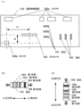
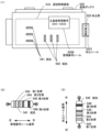
上記目的を達成するために、以下に示すような、遊技機が提供される。遊技機は、外部装置に情報を出力可能な外部情報端子板と、情報の出力に係る外部情報信号を外部情報端子板に出力可能な制御基板と、を備える。外部情報端子板は、少なくとも、レバー部の操作により電線を接続可能な情報出力端子と、情報出力端子を配設する外部情報端子基板とで構成される。外部情報端子基板は、情報出力端子が配設される配設面にレバー部の操作位置を表示する。制御基板は、複数の部材で構成される収容ケースに収容され、少なくとも、遊技の進行を制御するプロセッサと、検査の用に供し遊技の用に供しない検査用コネクタと、カラーコードによって定格を表示する受動素子と、外部情報信号の出力に関わる電子部品を備える。収容ケースは、複数の部材を、第1側から第2側の方向に所定情報を表示する封止シールにより封止される。検査用コネクタは、プロセッサの上下方向または左右方向における所定方向にオフセットされて制御基板に実装される。受動素子のうち第1の受動素子は、所定情報と平行、かつカラーコードの第1色帯が第1側であって所定方向における検査用コネクタ側となるように制御基板に実装される。受動素子のうち第2の受動素子は、所定情報と直交かつカラーコードの第1色帯が所定方向における検査用コネクタ側となるように制御基板に実装される。 In order to achieve the above object, a gaming machine as shown below is provided. The gaming machine includes an external information terminal board that can output information to an external device, and a control board that can output external information signals related to output of information to the external information terminal board. The external information terminal board is composed of at least an information output terminal to which an electric wire can be connected by operating a lever part, and an external information terminal board on which the information output terminal is arranged. The external information terminal board displays the operation position of the lever section on the installation surface where the information output terminal is installed. The control board is housed in a storage case made up of multiple members, and includes at least a processor that controls the progress of the game, a connector for testing but not for playing, and a color code to display the rating. and electronic components related to the output of external information signals . The housing case seals the plurality of members with a seal that displays predetermined information from the first side to the second side . The test connector is mounted on the control board offset in a predetermined direction in the vertical or horizontal direction of the processor. A first passive element among the passive elements is mounted on the control board so that it is parallel to the predetermined information and the first color band of the color code is on the first side, which is on the inspection connector side in the predetermined direction . The second passive element among the passive elements is mounted on the control board so that it is perpendicular to the predetermined information and the first color band of the color code is on the test connector side in the predetermined direction.
1態様によれば、遊技機において、外部情報端子板における好適な操作環境を有する。 According to one aspect, a gaming machine has a suitable operating environment on an external information terminal board.
以下、図面を参照して実施形態を詳細に説明する。
[第1の実施形態]
まず、第1の実施形態を図面にもとづいて説明する。図1は、第1の実施形態の遊技機
の一例を示す斜視図である。
Hereinafter, embodiments will be described in detail with reference to the drawings.
[First embodiment]
First, a first embodiment will be described based on the drawings. FIG. 1 is a perspective view showing an example of a gaming machine according to the first embodiment.
第1の実施形態の遊技機10は、前面枠12を備え、該前面枠12は、外枠(支持枠)
11に開閉回動可能に組み付けられている。遊技盤30(図2参照)は、前面枠12の表
側に形成された収納部(図示省略)に収納されている。また、前面枠(本体枠)12には
、遊技盤30の前面を覆うカバーガラス(透明部材)14を備えたガラス枠(透明板保持
枠)15が取り付けられている。
The
11 so that it can be rotated to open and close. The game board 30 (see FIG. 2) is stored in a storage section (not shown) formed on the front side of the
また、ガラス枠15の左右には、内部にランプやLED等を内蔵し装飾や演出、および
異常発生時の報知(たとえば、払出異常が発生した場合はランプやLED等を異常報知色
(たとえば、赤色)で点灯(点滅)させる)のために発光する枠装飾装置18や、音響(
たとえば、効果音)を発するスピーカ(上スピーカ)19aが設けられている。さらに、
前面枠12の下部にもスピーカ(下スピーカ)19bが設けられている。また、異常発生
時はスピーカ19a,19bから音声で異常内容が報知されるようになっている。なお、
ガラス枠15の所定部位に払出異常報知用のランプを設けるようにしてもよい。
In addition, lamps, LEDs, etc. are built into the left and right sides of the
For example, a speaker (upper speaker) 19a that emits sound effects is provided. moreover,
A speaker (lower speaker) 19b is also provided at the bottom of the
A lamp for notifying a dispensing abnormality may be provided at a predetermined portion of the
また、前面枠12の下部には、図示しない打球発射装置に遊技球を供給する上皿(貯留
皿)21、遊技機10の裏面側に設けられている払出ユニットから払い出された遊技球が
流出する上皿球出口22、上皿21が一杯になった状態で払い出された遊技球を貯留する
下皿(受皿)23および打球発射装置の操作部24等が設けられている。さらに、上皿2
1の上縁部には、遊技者が各種オプションの設定をおこなうオプション設定部25が設け
られている。このオプション設定部25の上面の周囲には複数の選択ボタンスイッチ25
aが設けられ、オプション設定部25の上面の中央には決定ボタンスイッチ25bが設け
られている。なお、オプション設定部25は、遊技者が演出態様を設定する演出設定部と
して機能する。この場合、選択ボタンスイッチ25aは、演出態様を選択する演出ボタン
スイッチとして機能し、決定ボタンスイッチ25bは、演出態様を決定する決定ボタンス
イッチとして機能する。さらに、前面枠12下部右側には、前面枠12やガラス枠15を
開放したり施錠したりする鍵を挿入するための鍵穴26が設けられている。
Further, at the lower part of the
An
a, and a
なお、選択ボタンスイッチ25aが演出ボタンスイッチとして機能する場合、遊技機1
0は、選択ボタンスイッチ25aと決定ボタンスイッチ25bとから受け付けた遊技者の
操作にもとづいて、遊技者の操作を介入させた演出をおこなうことができる。たとえば、
遊技者の操作を介入させた演出は、表示装置(変動表示装置)41(図2参照)における
変動表示ゲーム(飾り特図変動表示ゲーム)における演出があり、遊技機10は、表示装
置41に表示するキャラクタを動作させたり、表示装置41に表示される飾り特図変動表
示ゲームにおける識別情報を停止させたりすることができる。
Note that when the
Based on the player's operations received from the
The effect that involves the player's operation is the effect in the variable display game (decoration special figure variable display game) on the display device (variable display device) 41 (see FIG. 2), and the
また、オプション設定部25の右方には、遊技者が隣接する球貸機から球貸しを受ける
場合に操作する球貸ボタン27、球貸機のカードユニットからプリペイドカードを排出さ
せるために操作する排出ボタン28、プリペイドカードの残高を表示する残高表示部(図
示省略)等が設けられている。この第1の実施形態の遊技機10においては、遊技者が上
記操作部24を回動操作することによって、打球発射装置が上皿21から供給される遊技
球を遊技盤30前面の遊技領域32(図2参照)に向かって発射する。また、遊技者が選
択ボタンスイッチ25aおよび決定ボタンスイッチ25bを操作することによって、たと
えば、スピーカ19a,19bから放射される音量を設定したり、遊技盤30の明るさを
設定したりすることができる。
Further, on the right side of the
次に、遊技盤30について図2を用いて説明する。図2は、第1の実施形態の遊技盤の
一例を示す正面図である。
遊技盤30の表面には、ガイドレール31で囲われた略円形状の遊技領域32が形成さ
れている。遊技領域32は、遊技盤30の四隅に各々設けられた樹脂製のサイドケース3
3およびガイドレール31に囲繞されて構成される。遊技領域32には、ほぼ中央に表示
装置(変動表示装置)41を備えたセンターケース(遊技演出構成体)40が配置されて
いる。表示装置41は、センターケース40に設けられた凹部に、センターケース40の
前面より奥まった位置に取り付けられている。すなわち、センターケース40は表示装置
41の表示領域の周囲を囲い、表示装置41の表示面よりも前方へ突出し、周囲の遊技領
域32から遊技球が飛び込みにくくなるように形成されている。
Next, the
A substantially
3 and a
表示装置41は、たとえば、LCD(液晶表示器)、CRT(Cathode Ray Tube:ブラ
ウン管)等の表示画面を有する装置で構成されている。表示画面の画像を表示可能な領域
(表示領域)には、複数の識別情報(特別図柄)や特図変動表示ゲームを演出するキャラ
クタや演出効果を高める背景画像等の遊技に関する情報が表示される。表示装置41の表
示画面においては、識別情報として割り当てられた複数の特別図柄が変動表示(可変表示
)されて、特図変動表示ゲームに対応した飾り特図変動表示ゲームがおこなわれる。また
、表示画面には、遊技の進行にもとづく演出のための画像(たとえば、大当り表示画像、
ファンファーレ表示画像、エンディング表示画像等)が表示される。
The
Fanfare display image, ending display image, etc.) are displayed.
また、センターケース40の上部には、動作することによって遊技の演出をおこなう盤
演出装置44が備えられている。この盤演出装置44は、図2に示す状態から表示装置4
1の中央へ向けて動作可能となっている。
Further, the upper part of the center case 40 is provided with a
It is possible to move toward the center of 1.
遊技領域32におけるセンターケース40の側方右側には、普図変動表示ゲームの開始
条件を与える普通図柄始動ゲート(普図始動ゲート)34が設けられている。普図始動ゲ
ート34に入賞した遊技球(普図始動ゲート34を通過する遊技球)は、ゲートスイッチ
34a(図3参照)により検出される。
On the right side of the center case 40 in the
また、遊技領域32におけるセンターケース40の下方左側には、二つの一般入賞口3
5が配置され、センターケース40の下方右側であって後述する特別変動入賞装置38の
右部には、一つの一般入賞口35が配置されている。これら一般入賞口35に入賞した遊
技球は、入賞口スイッチ35a(図3参照)により検出される。
In addition, on the lower left side of the center case 40 in the
5 is arranged, and one general winning
また、遊技領域32におけるセンターケース40の下方には、第1特図変動表示ゲーム
(特図1変動表示ゲーム)の開始条件を与える第1始動入賞口(始動入賞領域)をなす始
動入賞口36(始動口1)が設けられている。始動入賞口36に入賞した遊技球は、始動
口1スイッチ36a(図3参照)により検出される。
In addition, below the center case 40 in the
また、普図始動ゲート34よりも下方位置であって、センターケース40の右部には、
第1特図変動表示ゲーム(特図1変動表示ゲーム)の開始条件を与える普通変動入賞装置
37(第1始動入賞口、始動入賞領域)が設けられている。普通変動入賞装置37(始動
口1)は、上端側が右方に倒れる方向に回動することで開放して遊技球が流入し易い状態
に変換可能な可動部材37bを備えており、この可動部材37bは、常時はほぼ鉛直とな
って遊技球が流入できない閉じた閉状態(遊技者にとって不利な状態)を保持している。
そして、普図変動表示ゲームの結果が所定の停止表示態様となった場合には、駆動装置と
しての普電ソレノイド37c(図3参照)によって上端側が右方に倒れるように回動して
普通変動入賞装置37に遊技球が流入し易い開状態(遊技者にとって有利な状態)に変化
させられるようになっている。普通変動入賞装置37に入賞した遊技球は、始動口1スイ
ッチ37a(図3参照)により検出される。なお、普通変動入賞装置37が閉状態でも入
賞できるようにし、閉状態では開状態よりは入賞しにくいものとしても良い。普通変動入
賞装置37は普通電動役物(普電)に相当する。
Further, at a lower position than the general
A normal variable winning device 37 (first starting winning opening, starting winning area) is provided which provides starting conditions for the first special figure variable display game (
When the result of the general figure fluctuation display game is a predetermined stop display mode, the upper end side is rotated so as to fall to the right by the general
普通変動入賞装置37の右方には、遊技球が流下可能な流下路91が形成され、普通変
動入賞装置37に入賞しなかった遊技球は流下路91を通って下方へ流下する。この流下
路91の下部には始動入賞口92が設けられ、またこの流下路91の下方には誘導部93
が設けられている。誘導部93は上面94が左方へ下る傾斜面とされており、始動入賞口
92に入賞せずに下方へ流下する遊技球を上面94で受け止め、後述する特別変動入賞装
置38が存在する左方へ誘導するようになっている。
A
is provided. The guiding
始動入賞口92は、第2特図変動表示ゲーム(特図2変動表示ゲーム)の開始条件を与
える第2始動入賞口(始動入賞領域)であり、この始動入賞口92(始動口2)に入賞し
た遊技球は、始動口2スイッチ92a(図3参照)により検出される。
The
また、遊技領域32における始動入賞口36の下方には、特図変動表示ゲームの結果に
よって遊技球を受け入れない状態と受け入れ易い状態とに変換可能な特別変動入賞装置(
下大入賞口、大入賞口1)95が配設されている。特別変動入賞装置95は、開閉部材9
5cを有しており、補助遊技としての特図変動表示ゲームの結果如何によって開閉部材9
5cが大入賞口を閉じた閉状態(遊技者にとって不利な閉塞状態)から開閉部材95cが
遊技領域32を流下する遊技球を受け入れ可能な開状態(遊技者にとって有利な状態)に
変換する。すなわち特別変動入賞装置95は、駆動装置としての大入賞口1ソレノイド9
5b(図3参照)により駆動される開閉部材95cによって開閉される大入賞口(下大入
賞口、大入賞口1)を備え、特図1変動表示ゲームの結果による小当り遊技状態(第2特
別遊技状態)中は、大入賞口を閉じた状態から開いた状態に変換することにより大入賞口
内への遊技球の流入を容易にさせ、遊技者に所定の遊技価値(賞球)を付与するようにな
っている。なお、大入賞口の内部(入賞領域)には、当該大入賞口に入った遊技球を検出
する検出手段としての大入賞口スイッチ(カウントスイッチ)38a(図3参照)が配設
されている。
In addition, below the
A lower prize opening and a larger prize opening 1) 95 are provided. The special variable
5c, and depending on the result of the special figure variable display game as an auxiliary game, the opening/closing member 9
5c closes the big prize opening (closed state disadvantageous to the player) to an open state (advantageous state for the player) in which the opening/closing
5b (see FIG. 3), the large winning opening (lower large winning opening, large winning opening 1) is opened and closed by the opening/closing
また、遊技領域32におけるセンターケース40の右下には、特図変動表示ゲームの結
果によって遊技球を受け入れない状態と受け入れ易い状態とに変換可能な特別変動入賞装
置(上大入賞口、大入賞口2)38が配設されている。特別変動入賞装置38は、開閉部
材(開閉扉)38cを有しており、補助遊技としての特図変動表示ゲームの結果如何によ
って開閉部材38cが大入賞口を閉じた閉状態(遊技者にとって不利な閉塞状態)から開
閉部材38cが退避して遊技領域32を流下する遊技球を受け入れ可能な開状態(遊技者
にとって有利な状態)に変換する。すなわち特別変動入賞装置38は、駆動装置としての
大入賞口2ソレノイド38b(図3参照)により駆動される開閉部材38cによって開閉
される大入賞口(上大入賞口、大入賞口2)を備え、特図1変動表示ゲーム及び特図2変
動表示ゲームの結果による大当り遊技状態(第1特別遊技状態)中や、特図2変動表示ゲ
ームの結果による小当り遊技状態(第2特別遊技状態)中は、大入賞口を閉じた状態から
開いた状態に変換することにより大入賞口内への遊技球の流入を容易にさせ、遊技者に所
定の遊技価値(賞球)を付与するようになっている。なお、大入賞口の内部(入賞領域)
には、当該大入賞口に入った遊技球を検出する検出手段としての大入賞口スイッチ(カウ
ントスイッチ)38a(図3参照)が配設されている。
In addition, in the lower right corner of the center case 40 in the
A big winning hole switch (count switch) 38a (see FIG. 3) is provided as a detection means for detecting the game ball that has entered the big winning hole.
なお、大入賞口スイッチ38aは、本実施形態のように大入賞口が複数個あるときには
、それぞれに1個又は2個程度、全体としてx個設けられる(図3参照)。この第1の実
施形態の場合、第1特別変動入賞装置(下大入賞口、大入賞口1)をなす特別変動入賞装
置95は、大入賞口スイッチ38aが1個だけ配設されている。一方、第2特別変動入賞
装置(上大入賞口、大入賞口2)をなす特別変動入賞装置38は、大入賞口スイッチ38
aが複数個(たとえば2個)配設されている。また特別変動入賞装置95は、たとえば特
別変動入賞装置38に比べて大入賞口が小さい入賞装置(いわゆるミニアタッカー)であ
る。
In addition, when there are a plurality of big winning openings as in this embodiment, about one or two big winning
A plurality (for example, two) of a are arranged. Further, the special variable winning
また、センターケース40の左側側部には、ワープ口(ワープ入口)39aが設けられ
ている。ワープ口39aからワープ流路に流入した遊技球は、センターケース40内のス
テージ上を転動し、その一部がワープ出口39bに案内される。ワープ出口39bは、始
動入賞口36の直上に位置し、ワープ出口39bに案内された遊技球は、始動入賞口36
に入賞しやすくなる。
Further, a warp port (warp entrance) 39a is provided on the left side of the center case 40. The game ball that has flowed into the warp channel from the
It will be easier to win.
第1の実施形態の遊技機10においては、遊技球が流下する遊技領域32のうち、セン
ターケース40の左方の領域が左側遊技領域とされ、センターケース40の右方の領域が
右側遊技領域とされている。そして、遊技者が発射勢を調節して左側遊技領域へ遊技球を
発射(いわゆる左打ち)することで始動入賞口36や特別変動入賞装置95、一般入賞口
35(特別変動入賞装置38の右部にある一般入賞口35を除く)への入賞を狙うことが
でき、右側遊技領域へ遊技球を発射(いわゆる右打ち)することで普図始動ゲート34や
普通変動入賞装置37、特別変動入賞装置38などへの入賞を狙うことができるようにな
っている。
In the
また、遊技領域32の外側(ここでは遊技盤30の右下部)には、特図変動表示ゲーム
をなす第1特図変動表示ゲームや第2特図変動表示ゲームおよび普図始動ゲート34への
入賞をトリガとする普図変動表示ゲームの表示や、各種情報を表示する一括表示装置50
が設けられている。
In addition, outside the game area 32 (here, the lower right part of the game board 30), there are a first special symbol fluctuation display game, a second special symbol fluctuation display game, and a regular
is provided.
一括表示装置50は、LED等で構成されたラウンド表示部51と、特図1保留表示部
52と、特図1図柄表示部53と、特図2図柄表示部54と、普図図柄表示部55と、普
図保留表示部56と状態表示部57とを備える(図5参照)。一括表示装置50の詳細は
、後述する。
The
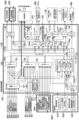
次に、遊技機の制御システムについて図3を用いて説明する。図3は、第1の実施形態
の遊技機の制御システムの一例を示すブロック図である。
遊技機10は、遊技制御装置100を備え、遊技制御装置100は、遊技を統括的に制
御する主制御装置(主基板)であって、遊技用マイクロコンピュータ(以下、遊技用マイ
コンと称する)111を有するCPU(Central Processing Unit)部110と、入力ポ
ートを有する入力部120と、出力ポートやドライバ等を有する出力部130と、CPU
部110と入力部120と出力部130との間を接続するデータバス140等からなる。
Next, the control system of the gaming machine will be explained using FIG. 3. FIG. 3 is a block diagram showing an example of the control system for the gaming machine according to the first embodiment.
The
The
CPU部110は、アミューズメントチップ(IC(Integrated Circuit))と呼ばれ
る遊技用マイコン111と、水晶振動子のような発振子を備え、遊技用マイコン111の
動作クロックやタイマ割込み、乱数生成回路の基準となるクロックを生成する発振回路(
水晶発振器)113等を有する。遊技制御装置100および該遊技制御装置100によっ
て駆動されるソレノイドやモータ等の電子部品は、電源装置400で生成されたDC(Di
rect Current)32V、DC12V、DC5V等所定のレベルの直流電圧が供給されて動
作可能にされる。
The CPU section 110 includes a
crystal oscillator) 113, etc. The
DC voltage of a predetermined level, such as 32 V (rect Current), 12 V DC, 5 V DC, etc., is supplied to enable operation.
電源装置400は、24Vの交流電源から上記DC32Vの直流電圧を生成するAC(
Alternating Current)-DCコンバータやDC32Vの電圧からDC12V、DC5V
等のより低いレベルの直流電圧を生成するDC-DCコンバータ等を有する通常電源部4
10と、遊技用マイコン111の内部のRAM(Random Access Memory)に対して停電時
に電源電圧を供給するバックアップ電源部420と、停電監視回路を有し、遊技制御装置
100に停電の発生、回復を知らせる停電監視信号やリセット信号等の制御信号を生成し
て出力する制御信号生成部430等を備える。
The
Alternating Current) - DC12V, DC5V from DC converter or DC32V voltage
A normal
10, a backup
第1の実施形態では、電源装置400は、遊技制御装置100と別個に構成されている
が、バックアップ電源部420および制御信号生成部430は、別個の基板上または遊技
制御装置100と一体、すなわち、主基板上に設けるように構成してもよい。遊技盤30
および遊技制御装置100は、機種変更の際に交換の対象となるので、第1の実施形態の
ように、電源装置400または主基板とは別の基板にバックアップ電源部420および制
御信号生成部430を設けることにより、交換の対象から外しコストダウンを図ることが
できる。
In the first embodiment, the
Since the
バックアップ電源部420は、電解コンデンサのような大容量のコンデンサ1つで構成
することができる。バックアップ電源は、遊技制御装置100の遊技用マイコン111(
特に内蔵RAM)に供給され、停電中または電源遮断後もRAMに記憶されたデータが保
持されるようになっている。制御信号生成部430は、たとえば通常電源部410で生成
された32Vの電圧を監視してそれがたとえば17V以下に下がると停電発生を検出して
停電監視信号を変化させるとともに、所定時間後にリセット信号を出力する。また、電源
投入時や停電回復時にもその時点から所定時間経過後にリセット信号を出力する。
The backup
In particular, the data stored in the RAM is retained even during a power outage or after the power is cut off. The control
また、遊技制御装置100にはRAM初期化スイッチ112が設けられている。このR
AM初期化スイッチ112が操作されると初期化スイッチ信号が生成され、これにもとづ
き遊技用マイコン111内のRAM111Cおよび払出制御装置200内のRAMに記憶
されている情報を強制的に初期化する処理がおこなわれる。特に限定されるわけではない
が、初期化スイッチ信号は、電源投入時に読み込まれ、停電監視信号は遊技用マイコン1
11が実行するメインプログラムのメインループの中で繰り返し読み込まれる。リセット
信号は強制割込み信号の一種であり、制御システム全体をリセットさせる。
Further, the
When the
11 is repeatedly read in the main loop of the main program executed. The reset signal is a type of forced interrupt signal and causes the entire control system to be reset.
また、遊技制御装置100には設定値変更スイッチ126と設定キースイッチ127が
設けられている。設定値変更スイッチ126は、たとえばプッシュスイッチであって、押
下操作を検出する。設定キースイッチ127は、設定キーを挿入してON状態とOFF状
態とを切り替え可能にする。遊技制御装置100は、遊技性能に関する設定を変更可能で
あって、停電中または電源遮断後もRAMに記憶された設定が保持されるようになってい
る。たとえば、遊技制御装置100は、特図1変動表示ゲームおよび特図2変動表示ゲー
ムの当り確率を6段階の設定に応じて変更可能にしている。
Further, the
遊技制御装置100は、設定キースイッチ127がON状態かつRAM初期化スイッチ
112がON状態での電源投入で、遊技機10の設定変更をおこなうことができる設定変
更モードに制御状態を遷移する。たとえば、遊技制御装置100は、設定変更モードにお
いて設定内容を確率設定値表示装置136に表示しながら設定値変更スイッチ126の押
下操作検出により設定1から設定6までをサイクリックに変更可能にする。確率設定値表
示装置136は、設定値を表示可能な表示装置であり、たとえば1桁の7セグメントLE
Dであって基板上に実装される。
When the power is turned on with the setting
D and is mounted on the board.
また、遊技制御装置100は、設定キースイッチ127がON状態かつRAM初期化ス
イッチ112がOFF状態での電源投入で、遊技機10の設定確認をおこなうことができ
る設定確認モードに制御状態を遷移する。たとえば、遊技制御装置100は、設定確認モ
ードにおいて設定内容を確率設定値表示装置136に表示する。
Furthermore, when the power is turned on with the setting
遊技用マイコン111は、CPU(中央処理ユニット:マイクロプロセッサ)111A
、読出し専用のROM(Read Only Memory)111Bおよび随時読出し書込み可能なRA
M111Cを備える。
The
, a read-only ROM (Read Only Memory) 111B and an RA that can be read and written at any time.
Equipped with M111C.
ROM111Bは、遊技制御のための不変の情報(プログラム、固定データ、各種乱数
の判定値等)を不揮発的に記憶し、RAM111Cは、遊技制御時にCPU111Aの作
業領域あるいは各種信号や乱数値の記憶領域として利用される。ROM111BまたはR
AM111Cとして、EEPROM(Electrically Erasable Programmable ROM)のよう
な電気的に書換え可能な不揮発性メモリを用いてもよい。
The ROM 111B stores immutable information (programs, fixed data, judgment values of various random numbers, etc.) for game control in a nonvolatile manner, and the RAM 111C serves as a work area for the CPU 111A or a storage area for various signals and random numbers during game control. used as. ROM111B or R
As the AM111C, an electrically rewritable nonvolatile memory such as EEPROM (Electrically Erasable Programmable ROM) may be used.
また、ROM111Bは、たとえば、特図変動表示ゲームの実行時間、演出内容、リー
チ状態の発生の有無等を規定する変動パターン(変動態様)を決定するための変動パター
ンテーブルを記憶している。変動パターンテーブルとは、始動記憶として記憶されている
変動パターン乱数1、変動パターン乱数2、および変動パターン乱数3をCPU111A
が参照して変動パターンを決定するためのテーブルである。また、変動パターンテーブル
には、結果がはずれとなる場合に選択されるはずれ変動パターンテーブル、結果が大当り
となる場合に選択される大当り変動パターンテーブル等が含まれる。さらに、これらのパ
ターンテーブルには、リーチ状態となった後の変動パターンである後半変動パターンを決
定するためのテーブル(後半変動グループテーブルや後半変動パターン選択テーブル等)
、リーチ状態となる前の変動パターンである前半変動パターンを決定するためのテーブル
(前半変動グループテーブルや前半変動パターン選択テーブル等)が含まれている。
Further, the ROM 111B stores a variation pattern table for determining a variation pattern (variation mode) that defines, for example, the execution time of the special figure variation display game, the contents of the performance, the presence or absence of a ready-to-reach state, and the like. The fluctuation pattern table refers to the fluctuation pattern
This is a table for reference to determine the fluctuation pattern. Further, the fluctuation pattern table includes a loss fluctuation pattern table that is selected when the result is a loss, a jackpot fluctuation pattern table that is selected when the result is a jackpot, and the like. Furthermore, these pattern tables include tables for determining the second half fluctuation pattern that is the fluctuation pattern after reaching the reach state (second half fluctuation group table, second half fluctuation pattern selection table, etc.)
, tables (first half variation group table, first half variation pattern selection table, etc.) for determining the first half variation pattern which is the variation pattern before reaching the reach state are included.
ここで、リーチ(リーチ状態)とは、表示状態が変化可能な表示装置を有し、該表示装
置が時期を異ならせて複数の表示結果を導出表示し、該複数の表示結果があらかじめ定め
られた特別結果態様となった場合に、遊技状態が遊技者にとって有利な遊技状態(特別遊
技状態)となる遊技機10において、複数の表示結果の一部がまだ導出表示されていない
段階で、既に導出表示されている表示結果が特別結果態様となる条件を満たしている表示
状態をいう。また、別の表現をすれば、リーチ状態とは、表示装置の変動表示制御が進行
して表示結果が導出表示される前段階にまで達した時点でも、特別結果態様となる表示条
件からはずれていない表示態様をいう。そして、たとえば、特別結果態様が揃った状態を
維持しながら複数の変動表示領域による変動表示をおこなう状態(いわゆる全回転リーチ
)もリーチ状態に含まれる。また、リーチ状態とは、表示装置の表示制御が進行して表示
結果が導出表示される前段階にまで達した時点での表示状態であって、表示結果が導出表
示される以前に決定されている複数の変動表示領域の表示結果の少なくとも一部が特別結
果態様となる条件を満たしている場合の表示状態をいう。
Here, reach (ready-to-reach state) refers to a display device that has a display state that can change, and that display device derives and displays multiple display results at different times, and that the multiple display results are determined in advance. In the
よって、たとえば、特図変動表示ゲームに対応して表示装置に表示される飾り特図変動
表示ゲームが、表示装置における左、中、右の変動表示領域の各々で所定時間複数の識別
情報を変動表示した後、左、右、中の順で変動表示を停止して結果態様を表示するもので
ある場合、左、右の変動表示領域で、特別結果態様となる条件を満たした状態(たとえば
、同一の識別情報)で変動表示が停止した状態がリーチ状態となる。またこの他に、すべ
ての変動表示領域の変動表示を一旦停止した時点で、左、中、右のうちいずれか二つの変
動表示領域で特別結果態様となる条件を満たした状態(たとえば、同一の識別情報となっ
た状態、ただし特別結果態様は除く)をリーチ状態とし、このリーチ状態から残りの一つ
の変動表示領域を変動表示するようにしてもよい。
Therefore, for example, a decorative special figure variable display game displayed on a display device in response to a special figure variable display game may vary a plurality of pieces of identification information for a predetermined time in each of the left, middle, and right variable display areas of the display device. After displaying, if the variable display is to be stopped in the order of left, right, and center to display the result mode, the left and right variable display areas will display a state that meets the conditions for the special result mode (for example, The state in which the variable display stops with the same identification information is the reach state. In addition, when the variable display of all variable display areas is temporarily stopped, any two of the left, middle, and right variable display areas meet the conditions for special result mode (for example, if the same The state that has become the identification information (excluding the special result mode) may be set as the ready-to-reach state, and the remaining one variable display area may be displayed in a variable manner from this ready-to-reach state.
そして、このリーチ状態には複数のリーチ演出が含まれ、特別結果態様が導出される可
能性が異なる(期待値が異なる)リーチ演出として、ノーマルリーチ(Nリーチ)、スペ
シャル1リーチ(SP1リーチ)、スペシャル2リーチ(SP2リーチ)、スペシャル3
リーチ(SP3リーチ)、プレミアリーチが設定されている。なお、期待値は、「リーチ
なし」<「ノーマルリーチ」<「スペシャル1リーチ」<「スペシャル2リーチ」<「ス
ペシャル3リーチ」<「プレミアリーチ」の順に高くなるようになっている。また、この
リーチ状態は、少なくとも特図変動表示ゲームで特別結果態様が導出される場合(大当り
となる場合)における変動表示態様に含まれるようになっている。すなわち、特図変動表
示ゲームで特別結果態様が導出されないと判定する場合(はずれとなる場合)における変
動表示態様に含まれることもある。よって、リーチ状態が発生した状態は、リーチ状態が
発生しない場合に比べて大当りとなる可能性の高い状態である。
This reach state includes multiple reach performances, and the reach performances with different possibilities of deriving special results (different expected values) include normal reach (N reach), special 1 reach (SP1 reach),
Reach (SP3 Reach) and Premier Reach are set. Note that the expected values increase in the order of "No reach"<"Normalreach"<"Special 1 reach"<"Special 2 reach"<"Special 3 reach"<"Premierreach". Moreover, this reach state is included in the variable display mode at least when a special result mode is derived in the special symbol variable display game (when it becomes a jackpot). That is, it may be included in the variable display mode when it is determined that the special result mode is not derived in the special figure variable display game (when the result is a loss). Therefore, a state in which a ready-to-win state occurs is a state in which there is a higher possibility of a jackpot than in a case in which a ready-to-reach state does not occur.
CPU111Aは、ROM111B内の遊技制御用プログラムを実行して、払出制御装
置200や演出制御装置300に対する制御信号(コマンド)を生成したり、ソレノイド
や表示装置の駆動信号を生成し出力して遊技機10全体の制御をおこなう。また、図示し
ないが、遊技用マイコン111は、特図変動表示ゲームの当りを判定するための大当り乱
数や大当りの図柄を決定するための大当り図柄乱数、特図変動表示ゲームでの変動パター
ン(各種リーチやリーチ無しの変動表示における変動表示ゲームの実行時間等を含む)を
決定するための変動パターン乱数、普図変動表示ゲームの当りを判定するための当り乱数
等を生成するための乱数生成回路と、発振回路113からの発振信号(原クロック信号)
にもとづいてCPU111Aに対する所定周期(たとえば、4m秒(ms))のタイマ割
込み信号や乱数生成回路の更新タイミングを与えるクロックを生成するクロックジェネレ
ータを備えている。
The CPU 111A executes the game control program in the ROM 111B, generates control signals (commands) for the
The CPU 111A is provided with a clock generator that generates a timer interrupt signal of a predetermined period (for example, 4 milliseconds (ms)) and a clock that provides update timing for the random number generation circuit based on the CPU 111A.
また、CPU111Aは、特図変動表示ゲームに関する処理において、ROM111B
に記憶されている複数の変動パターンテーブルの中から、いずれか一の変動パターンテー
ブルを取得する。具体的には、CPU111Aは、特図変動表示ゲームの遊技結果(当り
(大当りまたは小当り)またははずれ)や、現在の遊技状態としての特図変動表示ゲーム
の確率状態(通常確率状態または高確率状態)、現在の遊技状態としての普通変動入賞装
置37の動作状態(時短動作状態)、始動記憶数等にもとづいて、複数の変動パターンテ
ーブルの中から、いずれか一の変動パターンテーブルを選択して取得する。ここで、CP
U111Aは、特図変動表示ゲームを実行する場合に、ROM111Bに記憶された複数
の変動パターンテーブルのうち、いずれか一の変動パターンテーブルを取得する変動振り
分け情報取得手段をなす。
In addition, the CPU 111A uses the ROM 111B in processing related to the special figure fluctuation display game.
Any one of the plurality of variation pattern tables stored in the memory is acquired. Specifically, the CPU 111A determines the game result (hit (big hit or small hit) or miss) of the special pattern fluctuation display game, and the probability state (normal probability state or high probability state) of the special pattern fluctuation display game as the current gaming state. one of the plurality of variation pattern tables is selected based on the operating state (time-saving operation state) of the normal
U111A constitutes a fluctuation distribution information acquisition means for acquiring any one of the plurality of fluctuation pattern tables stored in the ROM 111B when executing the special figure fluctuation display game.
払出制御装置200は、CPU、ROM、RAM、入力インタフェース、出力インタフ
ェース等を備え、遊技制御装置100からの賞球払出し指令(コマンドやデータ)に従っ
て、遊技機10に設けられた払出ユニットの払出モータを駆動させ、賞球を払い出させる
ための制御をおこなう。また、払出制御装置200は、遊技機10に付設される球貸機の
カードユニットからの貸球要求信号にもとづいて払出ユニットの払出モータを駆動させ、
貸球を払い出させるための制御をおこなう。
The
Performs control for discharging rental balls.
遊技用マイコン111の入力部120には、始動入賞口36内の始動口1スイッチ36
a、普通変動入賞装置37内の始動口1スイッチ37a、始動入賞口92内の始動口2ス
イッチ92a、普図始動ゲート34内のゲートスイッチ34a、入賞口スイッチ35a、
特別変動入賞装置38の大入賞口スイッチ38aに接続され、これらのスイッチから供給
されるハイレベルが11Vでロウレベルが7Vのような負論理の信号が入力され、0V-
5Vの正論理の信号に変換するインタフェースチップ(近接I/F)121が設けられて
いる。この近接I/F121には、遊技機10に対する電波の発射を検出する盤電波セン
サ62の検出信号も入力される。また近接I/F121は、入力の範囲が7V-11Vと
されることで、センサや近接スイッチのリード線が不正にショートされたり、センサやス
イッチがコネクタから外されたり、リード線が切断されてフローティングになったような
異常な状態を検出することができ、異常検知信号を出力するように構成されている。
The
a, the starting
It is connected to the big
An interface chip (proximity I/F) 121 that converts into a 5V positive logic signal is provided. A detection signal from the board
なお、入賞口スイッチ35aについて説明すると、図3では入賞口スイッチ35aが1
個のブロックで示されているが、実際には複数(N個)の入賞口スイッチ35a(本実施
形態では3個)が遊技盤30に設けられており、それぞれの信号が異なる信号線で近接I
/F121に入力されている。また、図3では大入賞口スイッチ38aが1個のブロック
で示されているが、実際には複数(X個)の大入賞口スイッチ38a(本実施形態では3
個)が遊技盤30に設けられている。そして、これら複数の大入賞口スイッチ38aが、
それぞれ異なる信号線で接続されるか、あるいは、たとえばスイッチと遊技制御装置10
0(主基板)の間に存在する図示省略した中継基板上でワイヤードオア(wired OR)とい
う方式で遊技制御装置100に接続されている。盤電波センサ62や後述する磁気センサ
61も、異なる複数の信号線で接続されてもよいし、同様にワイヤードオアという方式で
遊技制御装置100に接続されていてもよい。
In addition, to explain the
Although shown as blocks, in reality, a plurality (N) of winning a prize opening switches 35a (three in this embodiment) are provided on the
/F121 is input. Also, in FIG. 3, the big winning
) are provided on the
For example, the switch and the
0 (main board) and is connected to the
近接I/F121の出力は、第2入力ポート123または第3入力ポート124へ供給
されデータバス140を介して遊技用マイコン111に読み込まれる。なお、近接I/F
121の出力のうち、始動口1スイッチ36a,37a、始動口2スイッチ92a、ゲー
トスイッチ34a、入賞口スイッチ35a、および大入賞口スイッチ38aの検出信号は
、第2入力ポート123へ入力される。なお、特図1の始動口スイッチである始動口1ス
イッチ36a,37aの信号の出力(近接I/F121からの出力)については、図3で
は1本の信号線で示しているが、実際には2本ある。
The output of the proximity I/
Among the outputs of 121, detection signals of starting
また、近接I/F121の出力のうち、盤電波センサ62の検出信号およびセンサやス
イッチの異常を検出した際に出力される異常検知信号は、第3入力ポート124に入力さ
れる。また、第3入力ポート124には、遊技機10の前面枠12等に設けられた不正検
出用の磁気センサ61の検出信号、遊技機10のガラス枠15等に設けられたガラス枠開
放検出スイッチ63の検出信号、遊技機10の前面枠(本体枠)12等に設けられた本体
枠開放検出スイッチ64の検出信号、設定値変更スイッチ126の検出信号、設定キース
イッチ127の検出信号、RAM初期化スイッチ112の検出信号が入力されるようにな
っている。
Further, among the outputs of the proximity I/
また、近接I/F121の出力のうち、第2入力ポート123への出力は、遊技制御装
置100から中継基板70を介して図示しない試射試験装置へも供給されるようになって
いる。さらに、近接I/F121の出力のうち、始動口1スイッチ36a,37aと始動
口2スイッチ92aの検出信号は、第2入力ポート123の他、遊技用マイコン111へ
入力されるように構成されている。
Further, among the outputs of the proximity I/
上記のように近接I/F121は、信号のレベル変換機能を有する。このようなレベル
変換機能を可能にするため、近接I/F121には、電源装置400から通常のICの動
作に必要なたとえば5Vのような電圧の他に、12Vの電圧が供給されるようになってい
る。
As described above, the proximity I/
第2入力ポート123が保持しているデータは、遊技用マイコン111が第2入力ポー
ト123に割り当てられているアドレスをデコードすることによって図示省略したイネー
ブル信号CE(Chip Enable)をアサート(有効レベルに変化)することによって、読み
出すことができる。第3入力ポート124や後述の第1入力ポート122も同様である。
The data held by the
また、入力部120には、払出制御装置200からの枠電波不正信号(前面枠12に設
けられた枠電波センサが電波を検出することにもとづき出力される信号)、払出ビジー信
号(払出制御装置200がコマンドを受付可能な状態か否かを示す信号)、払出異常ステ
ータス信号(払出異常を示すステータス信号)、シュート球切れスイッチ信号(払出し前
の遊技球の不足を示す信号)、オーバーフロースイッチ信号(下皿23に遊技球が所定量
以上貯留されていること(満杯になったこと)を検出したときに出力される信号)、タッ
チスイッチ信号(操作部24に設けられたタッチスイッチの入力にもとづく信号)、アウ
ト球検出スイッチ信号(アウト球を検出したときに出力される信号)を取り込んでデータ
バス140を介して遊技用マイコン111に供給する第1入力ポート122が設けられて
いる。
The
なお、アウト球検出スイッチ信号は、アウトセンサ(図示せず)が遊技機10のアウト
球を1個検出するごとにアウトセンサから出力される信号である。たとえば、アウト球検
出スイッチ信号は、遊技機10から遊技球(アウト球)を排出する排出口(図示せず)と
アウト口30aとの間に排出流路(図示せず)に設けられる。アウト球検出スイッチ信号
は、所定の稼働(たとえば、アウト球が60,000個)当たりの遊技性能(たとえば、
ベース)の算出に用いられ、算出した遊技性能は状態表示装置135に表示される。なお
、アウト球検出スイッチ信号は、演出制御装置300に入力されるものであってもよい。
その場合、アウト球検出スイッチ信号は、遊技演出や客待ち画面表示への切替トリガとな
る稼働状態の判定等に用いられるものであってもよい。たとえば、状態表示装置135は
、4桁の7セグメントLEDであって、10進数または16進数により遊技性能を表示す
ることができる。
The out ball detection switch signal is a signal output from the out sensor (not shown) every time the out sensor (not shown) detects one out ball of the
The calculated gaming performance is displayed on the
In that case, the out ball detection switch signal may be used to determine the operating state, which is a trigger for switching to a game production or customer waiting screen display. For example, the
また、遊技機10は、振動を検出する振動センサスイッチを設け、この振動センサスイ
ッチの検出信号が第1入力ポート122あるいは第3入力ポート124に入力されるよう
にしてもよい。
Furthermore, the
また、遊技制御装置100には、電源装置400からの停電監視信号やリセット信号等
の信号を遊技用マイコン111等に入力するためのシュミットバッファ125が設けられ
ており、シュミットバッファ125はこれらの入力信号からノイズを除去する機能を有す
る。電源装置400からの停電監視信号や、RAM初期化スイッチ112からの初期化ス
イッチ信号は、一旦、第1入力ポート122に入力され、データバス140を介して遊技
用マイコン111に取り込まれる。つまり、前述の各種スイッチからの信号と同等の信号
として扱われる。遊技用マイコン111に設けられている外部からの信号を受ける端子の
数には制約があるためである。
In addition, the
一方、シュミットバッファ125によりノイズ除去されたリセット信号RESETは、
遊技用マイコン111に設けられているリセット端子に直接入力されるとともに、出力部
130の各ポートに供給される。また、リセット信号RESETは、出力部130を介さ
ずに直接中継基板70に出力することで、試射試験装置へ出力するために中継基板70の
ポート(図示省略)に保持される試射試験信号をオフするように構成されている。また、
リセット信号RESETは、中継基板70を介して試射試験装置へ出力可能に構成される
ようにしてもよい。なお、リセット信号RESETは、入力部120の第1乃至第3入力
ポート122,123,124には供給されない。リセット信号RESETが入る直前に
遊技用マイコン111によって出力部130の各ポートに設定されたデータは、システム
の誤動作を防止するためリセットする必要があるが、リセット信号RESETが入る直前
に入力部120の各ポートから遊技用マイコン111が読み込んだデータは、遊技用マイ
コン111のリセットによって廃棄されるためである。
On the other hand, the reset signal RESET from which noise has been removed by the Schmitt buffer 125 is
The signal is input directly to the reset terminal provided on the
The reset signal RESET may be configured to be able to be output to the sight test equipment via the
出力部130には、遊技用マイコン111から演出制御装置300への通信経路および
遊技用マイコン111から払出制御装置200への通信経路に配されるシュミットバッフ
ァ132が設けられている。遊技制御装置100から演出制御装置300および払出制御
装置200へは、シリアル通信でデータが送信される。なお、遊技制御装置100から演
出制御装置300および払出制御装置200へのシリアル通信は、演出制御装置300側
から遊技制御装置100へ信号を入力できないようにした片方向通信とされている。
The
さらに、出力部130には、データバス140に接続され図示しない認定機関の試射試
験装置へ変動表示ゲームの特図図柄情報を知らせるデータや大当りの確率状態を示す信号
等を中継基板70を介して出力するバッファ133が実装可能に構成されている。このバ
ッファ133は、遊技店に設置される実機(量産販売品)としてのパチンコ遊技機の遊技
制御装置(主基板)には実装されない部品である。なお、近接I/F121から出力され
る始動口スイッチ等加工の必要のないスイッチの検出信号は、バッファ133を通さずに
中継基板70を介して試射試験装置へ供給される。
Further, the
一方、磁気センサ61や盤電波センサ62のようにそのままでは試射試験装置へ供給で
きない検出信号は、一旦、遊技用マイコン111に取り込まれて他の信号または情報に加
工されて、たとえば遊技機が遊技制御できない状態であることを示すエラー信号としてデ
ータバス140からバッファ133、中継基板70を介して試射試験装置へ供給される。
なお、中継基板70には、上記バッファ133から出力された信号を取り込んで試射試験
装置へ供給するポートや、バッファを介さないスイッチの検出信号の信号線を中継して伝
達するコネクタ等が設けられている。中継基板70上のポートには、遊技用マイコン11
1から出力されるチップイネーブル信号CE(図示省略)も供給され、このチップイネー
ブル信号CEにより選択制御されたポートの信号が試射試験装置へ供給されるようになっ
ている。
On the other hand, detection signals such as those from the
The
A chip enable signal CE (not shown) outputted from the chip enable signal CE is also supplied, and signals of ports selectively controlled by the chip enable signal CE are supplied to the sight test equipment.
また、出力部130には、データバス140に接続され、特別変動入賞装置38(大入
賞口)の開閉部材38cを開閉させる大入賞口ソレノイド38bの開閉データ、普通変動
入賞装置37の可動部材37bを開閉させる普電ソレノイド37cの開閉データ、および
状態表示装置135の表示データを出力するための第1出力ポート134aが設けられて
いる。また、出力部130には、確率設定値表示装置136の表示データを出力するため
の第2出力ポート134bが設けられている。また、出力部130には、一括表示装置5
0に表示する内容に応じてLEDのアノード端子が接続されているセグメント線のオン/
オフデータを出力するための第3出力ポート134c、一括表示装置50のLEDのカソ
ード端子が接続されているデジット線のオン/オフデータを出力するための第4出力ポー
ト134dが設けられている。
The
Turn on/off the segment line to which the LED anode terminal is connected depending on the content displayed on 0.
A third output port 134c for outputting off data and a
また、出力部130には、大当り情報等遊技機10に関する情報を外部情報端子板71
へ出力するための第5出力ポート134eが設けられている。外部情報端子板71には、
フォトリレーが備えられ、たとえば遊技店に設置された外部装置(情報収集端末や遊技場
内部管理装置(ホールコンピュータ)等)に接続可能であり、遊技機10に関する情報を
フォトリレーを介して外部装置に供給することができるようになっている。なお、外部装
置に供給する情報の一部は、第4出力ポート134dから出力される。また、第5出力ポ
ート134eからは、シュミットバッファ132を介して払出制御装置200に発射許可
信号も出力される。
The
A
A photorelay is provided and can be connected to an external device installed at a game parlor (an information collection terminal, a game hall internal management device (hall computer), etc.), and information regarding the
さらに、出力部130には、第1出力ポート134aから出力される大入賞口ソレノイ
ド38b、普電ソレノイド37cの開閉データ信号を受けてソレノイド駆動信号を生成し
出力する第1ドライバ(駆動回路)138a、第3出力ポート134cから出力される一
括表示装置50の電流供給側のセグメント線のオン/オフ駆動信号を出力する第2ドライ
バ138b、第4出力ポート134dから出力される一括表示装置50の電流引き込み側
のデジット線のオン/オフ駆動信号を出力する第3ドライバ138c、第5出力ポート1
34eや第4出力ポート134dから管理装置等の外部装置へ供給する外部情報信号を外
部情報端子板71へ出力する第4ドライバ138d、第1出力ポート134aから出力さ
れる状態表示装置135の表示データ信号を受けて状態表示装置135の駆動信号を生成
し出力する第5ドライバ138eが設けられている。
Furthermore, the
34e and the
上記第1ドライバ138aには、32Vで動作するソレノイドを駆動できるようにする
ため、電源電圧としてDC32Vが電源装置400から供給される。また、一括表示装置
50のセグメント線を駆動する第2ドライバ138bには、DC12Vが供給される。デ
ジット線を駆動する第3ドライバ138cは、表示データに応じたデジット線を電流で引
き抜くためのものであるため、電源電圧は12Vまたは5Vのいずれであってもよい。
The
12Vを出力する第2ドライバ138bによりセグメント線を介してLEDのアノード
端子に電流を流し込み、接地電位を出力する第3ドライバ138cによりカソード端子よ
りセグメント線を介して電流を引き抜くことで、ダイナミック駆動方式で順次選択された
LEDに電源電圧が流れて点灯される。外部情報信号を外部情報端子板71へ出力する第
4ドライバ138dは、外部情報信号に12Vのレベルを与えるため、DC12Vが供給
される。なお、バッファ133や第1出力ポート134a、第1ドライバ138a等は、
遊技制御装置100の出力部130、すなわち、主基板ではなく、中継基板70側に設け
るようにしてもよい。また、状態表示装置135、あるいは第5ドライバ138eと状態
表示装置135は、遊技制御装置100の出力部130、すなわち、主基板ではなく、外
部基板(図示せず)側に設けるようにしてもよい。
The second driver 138b that outputs 12V causes current to flow into the anode terminal of the LED via the segment line, and the
It may be provided on the
さらに、出力部130には、外部の検査装置490へ各遊技機の識別コードやプログラ
ム等の情報を送信するためのフォトカプラ139が設けられている。フォトカプラ139
は、遊技用マイコン111が検査装置490との間でシリアル通信によってデータの送受
信をおこなえるように双方通信可能に構成されている。なお、かかるデータの送受信は、
通常の汎用マイクロプロセッサと同様に遊技用マイコン111が有するシリアル通信端子
を利用しておこなわれるため、第1乃至第3入力ポート122,123,124のような
ポートは設けられていない。
Further, the
The
Since the serial communication terminal of the
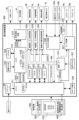
次に、演出制御装置300の構成について図4を用いて説明する。図4は、第1の実施
形態の演出制御装置の構成の一例を示すブロック図である。
演出制御装置300は、遊技用マイコン111と同様にアミューズメントチップ(IC
)からなる主制御用マイコン(CPU)311と、主制御用マイコン311からのコマン
ドやデータに従って表示装置41への映像表示のための画像処理をおこなうグラフィック
プロセッサとしてのVDP(Video Display Processor)312と、各種のメロディや効
果音等をスピーカ19a,19bから再生させるため音の出力を制御する音源LSI31
4を備えている。
Next, the configuration of the
The
), and a VDP (Video Display Processor) 312 as a graphic processor that performs image processing for displaying images on the
It is equipped with 4.
主制御用マイコン311には、CPUが実行するプログラムや各種データを格納したP
ROM(プログラマブルリードオンリメモリ)からなるPROM321、作業領域を提供
するRAM322、停電時に電力が供給されなくとも記憶内容を保持可能なFeRAM(
Ferroelectric RAM)323、現在の日時(年月日や曜日、時刻等)を示す情報を生成す
る計時手段をなすRTC(リアルタイムクロック)338が接続されている。なお、主制
御用マイコン311の内部にも作業領域を提供するRAM311aが設けられている。ま
た、主制御用マイコン311には、WDT(ウォッチドッグ・タイマ)回路324が接続
されている。主制御用マイコン311は、遊技用マイコン111からのコマンド(演出コ
マンド)を解析し、演出内容を決定してVDP312へ出力映像の内容を指示したり、音
源LSI314への再生音の指示、装飾ランプの点灯、モータやソレノイドの駆動制御、
演出時間の管理等の処理を実行したりする。
The
An RTC (real-time clock) 338, which serves as a clock means for generating information indicating the current date and time (year, month, day, day of the week, time, etc.), is connected. Note that a RAM 311a that provides a work area is also provided inside the
Performs processing such as managing performance time.
VDP312には、作業領域を提供するRAM312aや、画像を拡大、縮小処理する
ためのスケーラ312bが設けられている。また、VDP312には、キャラクタ画像や
映像データが記憶された画像ROM325や、画像ROM325から読み出されたキャラ
クタ等の画像データを展開したり加工したりするのに使用される超高速なVRAM326
が接続されている。
The
is connected.
特に限定されるわけではないが、主制御用マイコン311とVDP312との間は、パ
ラレル方式でデータの送受信がおこなわれるように構成されている。パラレル方式でデー
タを送受信することで、シリアルの場合よりも短時間にコマンドやデータを送信すること
ができる。
Although not particularly limited, the
VDP312から主制御用マイコン311へは、表示装置41の映像とガラス枠15や
遊技盤30に設けられている装飾ランプの点灯を同期させるための垂直同期信号VSYN
C、データの送信タイミングを与える同期信号STSが入力される。なお、VDP312
から主制御用マイコン311へは、VRAMへの描画の終了等処理状況を知らせるため割
込み信号INT0~nおよび主制御用マイコン311からのコマンドやデータの受信待ち
の状態にあることを知らせるためのウェイト信号WAIT等も入力される。
A vertical synchronization signal VSYN is sent from the
C. A synchronization signal STS that provides data transmission timing is input. In addition, VDP312
The
演出制御装置300には、LVDS(Low Voltage Differential Signaling:小振幅信
号伝送)方式で表示装置41へ送信する映像信号を生成する信号変換回路313が設けら
れている。VDP312から信号変換回路313へは、映像データ、水平同期信号HSY
NCおよび垂直同期信号VSYNCが入力されるようになっており、VDP312で生成
された映像は、信号変換回路313を介して表示装置41に表示される。
The
NC and vertical synchronization signal VSYNC are input, and the video generated by
音源LSI314には、音声データが記憶された音声ROM327が接続されている。
主制御用マイコン311と音源LSI314は、アドレス/データバス340を介して接
続されている。また、音源LSI314から主制御用マイコン311へは、割込み信号I
NTが入力されるようになっている。演出制御装置300には、ガラス枠15に設けられ
た上スピーカ19aおよび前面枠12に設けられた下スピーカ19bを駆動するオーディ
オパワーアンプ等からなるアンプ回路337が設けられており、音源LSI314で生成
された音声はアンプ回路337を介して上スピーカ19aおよび下スピーカ19bから出
力される。
An audio ROM 327 storing audio data is connected to the
The
NT is now input. The
また、演出制御装置300には、遊技制御装置100から送信されてくるコマンドを受
信するインタフェースチップ(コマンドI/F)331が設けられている。このコマンド
I/F331を介して、遊技制御装置100から演出制御装置300へ送信された飾り特
図保留数コマンド、飾り特図コマンド、変動コマンド、停止情報コマンド等を、演出制御
指令信号(演出コマンド)として受信する。遊技制御装置100の遊技用マイコン111
はDC5Vで動作し、演出制御装置300の主制御用マイコン311はDC3.3Vで動
作するため、コマンドI/F331には信号のレベル変換の機能が設けられている。
Further, the
operates at DC5V, and the
また、演出制御装置300には、遊技盤30(センターケース40を含む)に設けられ
ているLED(発光ダイオード)などを有する盤装飾装置46を駆動制御する盤装飾LE
D制御回路332、ガラス枠15に設けられているLED(発光ダイオード)を有する枠
装飾装置(たとえば枠装飾装置18等)を駆動制御する枠装飾LED制御回路333、遊
技盤30(センターケース40を含む)に設けられている盤演出装置44(たとえば表示
装置41における演出表示と協働して演出効果を高める可動役物等)を駆動制御する盤演
出可動体制御回路334が設けられている。ランプやモータおよびソレノイド等を駆動制
御するこれらの制御回路332~334は、アドレス/データバス340を介して主制御
用マイコン311と接続されている。なお、ガラス枠15にモータ(たとえば演出用の装
置を動作させるモータ)等の駆動源を備えた枠演出装置を設け、この枠演出装置を駆動制
御する枠演出可動体制御回路を備えていてもよい。
In addition, the
さらに、演出制御装置300には、ガラス枠15に設けられたオプション設定部25の
選択ボタンスイッチ25aおよび決定ボタンスイッチ25bと、盤演出装置44内のモー
タの初期位置等を検出する演出役物スイッチ47(演出モータスイッチ)のオン/オフ状
態を検出して主制御用マイコン311へ検出信号を入力する機能や、演出制御装置300
に設けられた音量調節スイッチ335の状態を検出して主制御用マイコン311へ検出信
号を入力する機能を有するスイッチ入力回路336が設けられている。
Furthermore, the
A
電源装置400の通常電源部410は、上記のような構成を有する演出制御装置300
やそれによって制御される電子部品に対して所望のレベルの直流電圧を供給するため、モ
ータやソレノイドを駆動するためのDC32V、液晶パネルからなる表示装置41、モー
タやLEDを駆動するためのDC12V、コマンドI/F331の電源電圧となるDC5
Vの他に、モータやLED、スピーカを駆動するためのDC15Vの電圧を生成するよう
に構成されている。さらに、主制御用マイコン311として、3.3Vまたは1.2Vの
ような低電圧で動作するLSIを使用する場合には、DC5VにもとづいてDC3.3V
やDC1.2Vを生成するためのDC-DCコンバータが演出制御装置300に設けられ
る。なお、DC-DCコンバータは通常電源部410に設けるようにしてもよい。
The normal
In order to supply a desired level of DC voltage to the electronic components controlled by it, 32V DC to drive the motor and solenoids, a
In addition to V, it is configured to generate a DC 15V voltage for driving a motor, LED, and speaker. Furthermore, when using an LSI that operates at a low voltage such as 3.3V or 1.2V as the
The
電源装置400の制御信号生成部430により生成されたリセット信号は、主制御用マ
イコン311に供給され、当該デバイスをリセット状態にする。また、主制御用マイコン
311から出力される形で、VDP312(VDPRESET信号)、音源LSI314
およびアンプ回路337(SNDRESET信号)、ランプやモータ等を駆動制御する制
御回路332~334(IORESET信号)に供給され、これらをリセット状態にする
。また、演出制御装置300には遊技機10の各所を冷却する冷却FAN45が接続され
、演出制御装置300の電源が投入された状態では冷却FAN45が駆動するようにされ
ている。また、演出制御装置300を構成する回路基板は、サブ制御基板(サブ基板とも
いう)に相当する。
The reset signal generated by the control
The signal is also supplied to the amplifier circuit 337 (SNDRESET signal) and the
なお、遊技機10における設定は、以下のようにしておこなうことで不正防止対策を図
るようにしてもよい。
(1)遊技制御装置100は、設定変更時に遊技用マイコン111内のRAM111C
および払出制御装置200内のRAMに記憶されている情報を強制的に初期化する処理を
実行する。これにより、遊技機10は、異なる設定値に跨って遊技制御をおこなうことを
防止する。
Note that the settings in the
(1) The
And a process of forcibly initializing the information stored in the RAM in the
(2)遊技制御装置100は、設定変更時および設定確認時に外部情報端子板71から
セキュリティ信号を出力する。これにより、遊技機10は、設定変更あるいは設定確認が
あったことを外部接続機器(たとえば、ホールコンピュータや、呼出ランプ等の情報開示
機器)に対して通知することができる。セキュリティ信号を入力した外部接続機器は、設
定変更あるいは設定確認があったことを報知手段(ランプや音(音声を含む)等)により
報知することができる。なお、遊技制御装置100は、設定変更と設定確認とで共通のセ
キュリティ信号を出力してもよいし、設定変更と設定確認とを区別可能なセキュリティ信
号を出力してもよい。
(2) The
(3)遊技制御装置100は、基板ボックスに収容されて前面枠12の裏面側に取り付
けられる。遊技制御装置100は、所要の操作部(RAM初期化スイッチ112、設定値
変更スイッチ126、設定キースイッチ127)、各種コネクタ等が外部に臨む以外、封
止された基板ボックスによって保護される。これにより、設定変更あるいは設定確認の移
行契機となる主媒体(遊技用マイコン111等)は、封止された基板ボックスによって保
護される。また、遊技制御装置100は、設定キースイッチ127を外部に臨ませて、設
定キースイッチ127以外の所要の操作部(RAM初期化スイッチ112、設定値変更ス
イッチ126)を封止された基板ボックスによって保護するものであってもよい。
(3) The
(4)遊技制御装置100は、設定変更あるいは設定確認の移行契機となる主媒体(遊
技用マイコン111等)へのアクセスに設定キースイッチ127の操作を必須とすること
で、設定キーを有しない第三者の主媒体へのアクセスを排除する。なお、遊技制御装置1
00は、設定キースイッチ127の操作によって、所要の操作部(RAM初期化スイッチ
112、設定値変更スイッチ126)へのアクセスを可能にする構成としてもよい。たと
えば、遊技制御装置100は、設定キースイッチ127の操作によってRAM初期化スイ
ッチ112、設定値変更スイッチ126への物理的操作を可能にする構成(たとえば、操
作窓の開閉)としてもよいし、設定キースイッチ127の操作によってRAM初期化スイ
ッチ112、設定値変更スイッチ126への操作を電気的にあるいは論理的に有効化する
構成としてもよいし、これらの組合せによる構成としてもよい。
(4) The
00 may be configured to allow access to required operation units (
(5)遊技制御装置100は、所要の操作部(RAM初期化スイッチ112、設定値変
更スイッチ126、設定キースイッチ127)、所要の情報表示部(状態表示装置135
、確率設定値表示装置136)を遊技用マイコン111によって制御する。なお、遊技制
御装置100は、エラー解除に用いるエラー解除スイッチや、遊技開始契機を与える遊技
開始スイッチを備えるようにしてもよく、エラー解除スイッチや遊技開始スイッチもまた
遊技用マイコン111によって制御するようにしてもよい。
(5) The
, probability setting value display device 136) are controlled by the
(6)遊技制御装置100は、RAM初期化スイッチ112と設定キースイッチ127
の入力状態の組合せから4つの電源投入状態を決定する。遊技制御装置100は、RAM
初期化スイッチ112がON、設定キースイッチ127がONのとき、設定値を変更可能
な設定変更状態とし、RAM初期化スイッチ112がOFF、設定キースイッチ127が
ONのとき、設定値を確認可能な設定確認状態とし、RAM初期化スイッチ112がON
、設定キースイッチ127がOFFのとき、遊技用マイコン111内のRAM111Cお
よび払出制御装置200内のRAMに記憶されている情報を強制的に初期化するRAMク
リア(RWMクリア)状態とし、RAM初期化スイッチ112がOFF、設定キースイッ
チ127がOFFのとき、電源投入があった停電復旧(復電)状態とする。
(6) The
Four power-on states are determined from the combinations of input states. The
When the
When the setting
(7)遊技機10は、設定変更状態において、以下のようなステップで設定変更をおこ
なうことができる。電源OFFの状態で設定キースイッチ127がOFF状態で設定キー
を挿入する(ステップ1)。設定キーを操作(たとえば、回す)し、設定キースイッチ1
27をON状態に切り替える(ステップ2)。RAM初期化スイッチ112を押下操作(
ON)しながら電源を投入(電源スイッチON)することにより、設定変更状態となる(
ステップ3)。設定変更状態において、設定値変更スイッチ126の押下操作1回ごとに
設定値を変更する(ステップ4)。設定キーを操作(たとえば、回す)し、設定キースイ
ッチ127をOFF状態に切り替えることで設定値を確定し、設定変更状態を終了する(
ステップ5)。
(7) In the setting change state, the
27 to the ON state (step 2). Press down the RAM initialization switch 112 (
By turning on the power (turning on the power switch) while the power is on, the settings can be changed (
Step 3). In the setting change state, the set value is changed each time the set
Step 5).
このとき、報知手段(たとえば、表示装置41による表示、スピーカ19a,19bに
よる音(音声)、枠装飾装置18や盤装飾装置46による発光)により、ステップ3,4
で設定変更を報知し、ステップ5でRAMクリアを報知する。また、外部情報出力手段(
たとえば、外部情報端子板71)は、ステップ3,4でセキュリティ信号を出力し、ステ
ップ5でセキュリティ信号の出力を停止する。なお、遊技制御装置100は、ステップ5
におけるRAMクリア報知に先立ち、ステップ3でRAMクリアを実行する。すなわち、
遊技制御装置100は、RAMクリア報知よりも設定変更報知を優先することで、設定値
変更報知を迅速におこない不正防止対策としての効果向上を図っている。また、確率設定
値表示装置136は、ステップ1,2で消灯し、ステップ3,4で設定値を表示し、ステ
ップ5で消灯する。また、状態表示装置135は、ステップ1~4で消灯し、ステップ5
でベース値を表示する。なお、遊技機10は、状態表示装置135と確率設定値表示装置
136とを一体にして設けてもよく、たとえば、状態表示装置135が確率設定値表示装
置136を兼ねるようにしてもよい。その場合、状態表示装置135は、ステップ1,2
で消灯し、ステップ3,4で設定値を表示し、ステップ5でベース値を表示する。なお、
遊技制御装置100の遊技状態は、ステップ3,4で遊技開始前であり、ステップ5で遊
技開始し、以降遊技中となる。
At this time, the notification means (for example, display by the
In
For example, the external information terminal board 71) outputs a security signal in
Prior to the RAM clear notification in
By giving priority to setting change notification over RAM clear notification, the
to display the base value. Note that the
The light goes out, the set value is displayed in
The gaming state of the
(8)遊技機10は、設定確認状態において、以下のようなステップで設定確認をおこ
なうことができる。電源OFFの状態で設定キースイッチ127がOFF状態で設定キー
を挿入する(ステップ1)。設定キーを操作(たとえば、回す)し、設定キースイッチ1
27をON状態に切り替える(ステップ2)。RAM初期化スイッチ112を押下操作す
ることなく(OFF)電源を投入(電源スイッチON)することにより、設定確認状態と
なる(ステップ3)。設定キーを操作(たとえば、回す)し、設定キースイッチ127を
OFF状態に切り替えることで設定確認状態を終了する(ステップ4)。
(8) In the setting confirmation state, the
27 to the ON state (step 2). By turning on the power (power switch ON) without pressing the RAM initialization switch 112 (OFF), the setting confirmation state is entered (Step 3). The setting confirmation state is ended by operating (for example, turning) the setting key and switching the setting
このとき、報知手段(たとえば、表示装置41による表示、スピーカ19a,19bに
よる音(音声)、枠装飾装置18や盤装飾装置46による発光)により、ステップ3で設
定確認を報知する。また、外部情報出力手段(たとえば、外部情報端子板71)は、ステ
ップ3でセキュリティ信号を出力し、ステップ4でセキュリティ信号の出力を停止する。
また、確率設定値表示装置136は、ステップ1,2で消灯し、ステップ3で設定値を表
示し、ステップ4で消灯する。また、状態表示装置135は、ステップ1~3で消灯し、
ステップ4でベース値を表示する。なお、遊技機10は、状態表示装置135と確率設定
値表示装置136とを一体にして設けてもよく、たとえば、状態表示装置135が確率設
定値表示装置136を兼ねるようにしてもよい。その場合、状態表示装置135は、ステ
ップ1,2で消灯し、ステップ3で設定値を表示し、ステップ4でベース値を表示する。
なお、遊技制御装置100の遊技状態は、ステップ3で遊技開始前であり、ステップ4で
遊技開始し、以降遊技中となる。
At this time, setting confirmation is notified in
Further, the probability set
In
The gaming state of the
なお、遊技機10は、設定変更や設定確認を電源投入時の遊技開始前に限っておこなえ
るようにしている。これにより、遊技機10は、遊技中の設定変更や設定確認を排除し、
遊技中の動作保証を容易にしている。
Note that the
This makes it easy to guarantee operation during gaming.
次に、これらの制御回路においておこなわれる遊技制御について説明する。
遊技制御装置100の遊技用マイコン111のCPU111Aでは、普図始動ゲート3
4に備えられたゲートスイッチ34aからの遊技球の検出信号の入力にもとづき、普図の
当り判定用乱数値を抽出してROM111Bに記憶されている判定値と比較し、普図変動
表示ゲームの当りはずれを判定する処理をおこなう。そして、一括表示装置50の普図図
柄表示部55に、識別図柄(識別情報)を所定時間変動表示した後、停止表示する普図変
動表示ゲームを表示する処理をおこなう。この普図変動表示ゲームの結果が当りの場合は
、普図図柄表示部55に第1当り停止図柄~第3当り停止図柄の各々に対応した特別の結
果態様を表示するとともに、普電ソレノイド37cを動作させ、普通変動入賞装置37の
可動部材37bを所定時間(たとえば、0.5秒間または1.7秒間)上述のように開放
する制御をおこなう。すなわち、遊技制御装置100が、変換部材(可動部材37b)の
変換制御をおこなう変換制御実行手段をなす。なお、普図変動表示ゲームの結果がはずれ
の場合は、普図図柄表示部55にはずれの結果態様を表示する制御をおこなう。
Next, game control performed in these control circuits will be explained.
In the CPU 111A of the
Based on the input of the detection signal of the game ball from the gate switch 34a provided in 4, the random value for determining the hit of the regular figure is extracted and compared with the determination value stored in the ROM 111B, and the random value for determining the hit of the regular figure is extracted and compared with the determination value stored in the ROM 111B. Performs processing to determine hit or miss. Then, after displaying identification symbols (identification information) in a variable manner for a predetermined period of time on the common symbol display section 55 of the
また、始動入賞口36に備えられた始動口1スイッチ36aと普通変動入賞装置37に
備えられた始動口1スイッチ37aからの遊技球の検出信号の入力にもとづき始動入賞(
始動記憶)を記憶し、この始動記憶にもとづき、第1特図変動表示ゲームの大当り判定用
乱数値を抽出してROM111Bに記憶されている判定値と比較し、第1特図変動表示ゲ
ームの当りはずれを判定する処理をおこなう。また、始動入賞口92に備えられた始動口
2スイッチ92aからの遊技球の検出信号の入力にもとづき始動記憶を記憶し、この始動
記憶にもとづき、第2特図変動表示ゲームの大当り判定用乱数値を抽出してROM111
Bに記憶されている判定値と比較し、第2特図変動表示ゲームの当りはずれを判定する処
理をおこなう。
In addition, starting winnings (
Based on this starting memory, a random value for jackpot determination of the first special figure fluctuation display game is extracted and compared with the determination value stored in the ROM 111B, Performs processing to determine hit or miss. In addition, the starting memory is stored based on the input of the game ball detection signal from the starting
It compares it with the judgment value stored in B and performs a process of judging whether the second special symbol fluctuation display game is a hit or a miss.
そして、遊技制御装置100のCPU111Aは、上記の第1特図変動表示ゲームや第
2特図変動表示ゲームの判定結果を含む制御信号(演出制御コマンド、演出コマンド)を
、演出制御装置300に出力する。そして、一括表示装置50の特図1図柄表示部53や
特図2図柄表示部54に、識別図柄(識別情報)を所定時間変動表示した後、停止表示す
る特図変動表示ゲームを表示する処理をおこなう。すなわち、遊技制御装置100が、遊
技領域32を流下する遊技球の始動入賞領域(始動入賞口36、普通変動入賞装置37、
始動入賞口92)への入賞にもとづき変動表示ゲームの進行制御をおこなう遊技制御手段
をなす。
Then, the CPU 111A of the
It serves as a game control means for controlling the progress of the variable display game based on winnings in the starting winning hole 92).
また、演出制御装置300では、遊技制御装置100からの制御信号にもとづき、表示
装置41で特図変動表示ゲームに対応した飾り特図変動表示ゲームを表示する処理をおこ
なう。さらに、演出制御装置300では、遊技制御装置100からの制御信号にもとづき
、演出状態の設定や、スピーカ19a,19bからの音の出力、各種LEDの発光を制御
する処理等をおこなう。すなわち、演出制御装置300が、遊技(変動表示ゲーム等)に
関する演出を制御する演出制御手段をなす。
In addition, the
そして、遊技制御装置100のCPU111Aは、特図変動表示ゲームの結果が大当り
や小当りの場合は、特図1図柄表示部53や特図2図柄表示部54に特別結果態様や小当
り結果態様を表示するとともに、特別遊技状態や小当り遊技状態を発生させる処理(すな
わち、特別遊技や小当り遊技を実行する処理)をおこなう。第1特図変動表示ゲームや第
2特図変動表示ゲームの結果が大当りとなったことによる特別遊技状態を発生させる処理
においては、CPU111Aは、たとえば、大入賞口2ソレノイド38bにより特別変動
入賞装置38の開閉部材38cを開放させ、大入賞口2内への遊技球の流入を可能とする
制御をおこなう。この特別遊技状態でCPU111Aは、たとえば大入賞口2に所定個数
(たとえば、9個)の遊技球が入賞するか、大入賞口2の開放から所定の開放可能時間が
経過するかのいずれかの条件が達成されるまで大入賞口2を開放することを1ラウンドと
し、これを所定ラウンド回数継続する(繰り返す)制御(サイクル遊技)をおこなう。ま
た、第1特図変動表示ゲーム(特図1変動表示ゲーム)の結果が小当りとなったことによ
る小当り遊技状態を発生させる処理においては、CPU111Aは、たとえば、大入賞口
1ソレノイド95bにより特別変動入賞装置95の開閉部材95cを開放させ、大入賞口
1内への遊技球の流入を可能とする制御をおこなう。また、第2特図変動表示ゲーム(特
図2変動表示ゲーム)の結果が小当りとなったことによる小当り遊技状態を発生させる処
理においては、CPU111Aは、たとえば、大入賞口2ソレノイド38bにより特別変
動入賞装置38の開閉部材38cを開放させ、大入賞口2内への遊技球の流入を可能とす
る制御をおこなう。なお、これら小当り遊技状態で行われる大入賞口の開閉動作パターン
(開閉動作態様)は、たとえば200m秒だけ開閉部材を開状態に維持する動作を150
0m秒間隔で4回行うといったものである。このように、遊技制御装置100は、停止結
果態様が特別結果態様となった場合に、大入賞口を開閉する制御をおこなう大入賞口開閉
制御手段をなす。またCPU111Aは、特図変動表示ゲームの結果がはずれの場合は、
一括表示装置50の特図1図柄表示部53や特図2図柄表示部54にはずれの結果態様を
表示する制御をおこなう。
Then, when the result of the special pattern fluctuation display game is a jackpot or small win, the CPU 111A of the
This is done four times at 0 msec intervals. In this way, the
Control is performed to display the result mode of the loss on the special figure 1 symbol display section 53 and the special figure 2 symbol display section 54 of the
また、遊技制御装置100は、特図変動表示ゲームの結果態様にもとづき、特別遊技状
態の終了後に、遊技状態として高確率状態を発生可能となっている。この高確率状態は、
特図変動表示ゲームにて当り結果となる確率が、通常確率状態に比べて高い状態である。
また、第1特図変動表示ゲームおよび第2特図変動表示ゲームのどちらの特図変動表示ゲ
ームの結果態様にもとづき高確率状態となっても、第1特図変動表示ゲームおよび第2特
図変動表示ゲームの両方が高確率状態となる。
Further, the
The probability of a winning result in the special figure fluctuation display game is higher than the normal probability state.
In addition, even if a high probability state is achieved based on the result of either the first special figure fluctuation display game or the second special figure fluctuation display game, the first special figure fluctuation display game or the second special figure fluctuation display game Both of the variable display games are in a high probability state.
また、遊技制御装置100は、特図変動表示ゲームの結果態様にもとづき、特別遊技状
態の終了後に、遊技状態として時短状態(特定遊技状態、普図高確率状態)を発生可能と
なっている。この時短状態においては、普図変動表示ゲームの当り結果となる確率(普図
確率)を通常確率(普図低確率状態)である0よりも高い高確率(普図高確率状態)とす
ることが可能である。これにより、普通変動入賞装置37が普図低確率状態である場合よ
りも、単位時間当りの普通変動入賞装置37の開放時間が多くなるように制御するように
なっている。ここで、本実施形態における普通変動入賞装置37は、通常遊技状態におい
ては可動部材37bを開放しないように普図確率が「0」に設定されている。
In addition, the
また、時短状態において、普図変動表示ゲームの実行時間(普図変動時間)は、たとえ
ば、500m秒となり、普図変動表示ゲームの結果を表示する普図停止時間は、たとえば
、600m秒となり、普図変動表示ゲームが当り結果となって普通変動入賞装置37が開
放される場合に、第1当り停止図柄の開放時間(普電開放時間)と開放回数(たとえば、
500m秒×1回)、第2当り停止図柄の開放時間(普電開放時間)と開放回数(たとえ
ば、1700m秒×2回)、第3当り停止図柄の開放時間(普電開放時間)と開放回数(
たとえば、1700m秒×3回)、となるように設定することが可能である。
In addition, in the time saving state, the execution time of the general pattern fluctuation display game (normal pattern fluctuation time) is, for example, 500 msec, and the general pattern stop time for displaying the result of the general pattern fluctuation display game is, for example, 600 msec, When the normal variable prize display game results in a winning result and the normal
500ms x 1 time), the opening time of the 2nd winning stop symbol (normal power opening time) and the number of openings (for example, 1700ms x 2 times), the opening time of the 3rd winning stop symbol (normal power opening time) and opening Number of times (
For example, it is possible to set it to 1700 msec x 3 times).
なお、普図変動表示ゲームおよび普通変動入賞装置37を時短動作状態とする制御をお
こなうよう適宜普図変動表示ゲームの実行時間、普図停止時間、普電開放回数、普電開放
時間を設定してもよく、たとえば、時短状態においては、上述の普図変動表示ゲームの実
行時間(普図変動時間)を第1変動表示時間よりも短い第2変動表示時間となるように制
御することが可能である(たとえば、10000m秒が1000m秒)。また、時短状態
においては、普図変動表示ゲームの結果を表示する普図停止時間を第1停止時間よりも短
い第2停止時間となるように制御することが可能である(たとえば、1604m秒が70
4m秒)。また、時短状態においては、普図変動表示ゲームが当り結果となって普通変動
入賞装置37が開放される場合に、開放時間(普電開放時間)を通常状態(普図低確率状
態)の第1開放時間よりも長い第2開放時間となるように制御することが可能である(た
とえば、100m秒が1352m秒)。また、時短状態においては、普図変動表示ゲーム
の1回の当り結果に対して、普通変動入賞装置37の開放回数(普電開放回数)を第1開
放回数(たとえば、2回)よりも多い回数(たとえば、4回)の第2開放回数に設定する
ことが可能である。また、時短状態においては、普図変動表示ゲームの当り結果となる確
率(普図確率)を通常動作状態である場合の通常確率(普図低確率状態、たとえば、1/
251)よりも高い高確率(普図高確率状態、たとえば、250/251)とすることが
可能である。
In addition, in order to control the general figure fluctuation display game and the ordinary variable winning
4ms). In addition, in the time saving state, when the normal
251) (original high probability state, for example, 250/251).
時短状態においては、普図変動時間、普図停止時間、普電開放回数、普電開放時間、普
図確率のいずれか一つまたは複数を変化させることで普通変動入賞装置37を開状態に状
態変換する時間を通常よりも延長するようにする。また、変化させるものが異なる複数種
類の時短状態を設定することも可能である。また、当りとなった場合に第1開放態様と第
2開放態様のいずれかを選択するようにしてもよい。この場合、第1開放態様と第2開放
態様の選択確率を異ならせてもよい。また、高確率状態と時短状態は、それぞれ独立して
発生可能であり、両方を同時に発生することも可能であるし、一方のみを発生させること
も可能である。また時短状態は、普電サポート状態(普電サポート中、或いは電サポ中)
と称することもできる。
In the short time state, the normal
It can also be called.
また、第1の実施形態の遊技機10の場合、遊技制御装置100は、所定の大当りによ
り発生した時短状態終了後(電サポ終了後)に、第2特図変動表示ゲーム(特図2変動表
示ゲーム)の結果が小当りとなる確率をたとえば規定期間だけ高める特図2特別モード(
第2特図変動表示ゲームが特定結果となる確率を高める特定結果高確率状態)を発生可能
となっている。この特図2特別モードは一種の高確率状態である。
In the case of the
It is possible to generate a specific result high probability state in which the second special figure variable display game increases the probability of a specific result. This special figure 2 special mode is a kind of high probability state.
次に、この第1の実施形態の遊技機10のゲーム性(標準的な攻略法)の概略について
説明する。この遊技機10のゲーム性は、通常遊技状態(上述した特図2特別モード、特
別遊技状態、時短状態のうちの何れでもない状態)では左打ちを行って特図1変動表示ゲ
ームで大当りを狙い、特別遊技状態(大当り状態)や時短状態(電サポ中)では右打ちを
行い、特図2特別モードでは右打ちで特図2変動表示ゲームの小当りを狙い、特別遊技状
態や時短状態や特図2特別モードが終了して通常遊技状態になると左打ちに戻す、という
ものである。なお、上述の特図2特別モードが設けられていることにより、遊技者は、時
短状態終了後も通常遊技状態よりも高い期待感を維持して遊技できる可能性が生じ、遊技
の興趣が向上する。
Next, an outline of the game nature (standard strategy) of the
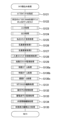
次に、一括表示装置の構成について図5を用いて説明する。図5は、第1の実施形態の
一括表示装置の一例を示す図である。一括表示装置50は、7セグメントLED_d1と
7セグメントLED_d2、およびLED_d3からLED_d18までの16個のLE
Dを備える。一括表示装置50は、7セグメントLED_d1と7セグメントLED_d
2、およびLED_d3からLED_d18の点灯態様により各種状態表示をおこなう。
Next, the configuration of the batch display device will be explained using FIG. 5. FIG. 5 is a diagram illustrating an example of the batch display device according to the first embodiment. The
Equipped with D. The
2, and various status displays are performed by the lighting manner of LED_d3 to LED_d18.
一括表示装置50は、7セグメントLED_d1と7セグメントLED_d2、および
LED_d3からLED_d18に各種状態表示機能を振り分けることで、ラウンド表示
部51と、特図1保留表示部52と、特図1図柄表示部53と、特図2図柄表示部54と
、普図図柄表示部55と、普図保留表示部56と、状態表示部57と、特図2保留表示部
58とを備える。ラウンド表示部51は、LED_d3からLED_d6の4個のLED
の点灯態様により、特図ゲームにおけるラウンド数を表示する。特図1保留表示部52は
、LED_d11とLED_d12の2個のLEDの点灯態様により、特図1ゲームにお
ける保留数を表示する。特図1図柄表示部53は、7セグメントLED_d1の8個のL
ED(7個のセグメントLEDと1個のドットLED)の点灯態様により、特図1ゲーム
における図柄を表示する。特図2図柄表示部54は、7セグメントLED_d2の8個の
LED(7個のセグメントLEDと1個のドットLED)の点灯態様により、特図2ゲー
ムにおける図柄を表示する。普図図柄表示部55は、LED_d8、LED_d10、お
よびLED_d18の3個のLEDの点灯態様により、普図ゲームにおける図柄を表示す
る。普図保留表示部56は、LED_d15とLED_d16の2個のLEDの点灯態様
により、普図ゲームにおける保留数を表示する。状態表示部57は、LED_d7、LE
D_d9、およびLED_d17の3個のLEDの点灯態様により、特図ゲームにおける
遊技状態を表示する。特図2保留表示部58は、LED_d13とLED_d14の2個
のLEDの点灯態様により、特図2ゲームにおける保留数を表示する。
The
The number of rounds in the special figure game is displayed depending on the lighting mode. The special figure 1 reservation display section 52 displays the number of reservations in the special figure 1 game by the lighting mode of two LEDs, LED_d11 and LED_d12. The special figure 1 symbol display section 53 has 8 L of 7 segment LED_d1.
The symbols in the special figure 1 game are displayed by the lighting mode of the ED (seven segment LEDs and one dot LED). The special figure 2 symbol display section 54 displays the symbols in the special figure 2 game by the lighting manner of eight LEDs (seven segment LEDs and one dot LED) of the 7 segment LED_d2. The common pattern symbol display section 55 displays the symbols in the common pattern game by the lighting modes of three LEDs, LED_d8, LED_d10, and LED_d18. The standard figure reservation display section 56 displays the number of pending figures in the standard figure game by the lighting mode of two LEDs, LED_d15 and LED_d16. The status display section 57 includes LED_d7, LE
The gaming state in the special figure game is displayed by the lighting manner of the three LEDs D_d9 and LED_d17. The special figure 2 reservation display section 58 displays the number of reservations in the special figure 2 game by the lighting mode of two LEDs, LED_d13 and LED_d14.
以下、このような遊技をおこなう遊技機の制御について説明する。まず、遊技制御装置
100の遊技用マイコン111によって実行される制御について説明する。遊技用マイコ
ン111による制御処理は、主に図6および図7に示すメイン処理と、所定時間周期(た
とえば4m秒)でおこなわれる図8に示すタイマ割込み処理とからなる。
The control of a gaming machine that plays such a game will be explained below. First, the control executed by the
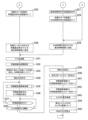
〔メイン処理〕
まず、メイン処理について説明する。図6は、第1の実施形態のメイン処理のフローチ
ャートを示す図(その1)であり、図7は、第1の実施形態のメイン処理のフローチャー
トを示す図(その2)である。メイン処理は、CPU111Aが実行する処理である。
[Main processing]
First, the main processing will be explained. FIG. 6 is a diagram (part 1) showing a flowchart of the main processing of the first embodiment, and FIG. 7 is a diagram (part 2) showing a flowchart of the main processing of the first embodiment. The main process is a process executed by the CPU 111A.
メイン処理は、電源が投入されることで開始される。このメイン処理においては、図6
および図7に示すように、まず、割込みを禁止する処理(ステップS1)をおこなってか
ら、割込みが発生したときにレジスタ等の値を退避する領域の先頭アドレスであるスタッ
クポインタを設定するスタックポインタ設定処理(ステップS2)をおこなう。次に、レ
ジスタバンク0を指定し(ステップS3)、所定のレジスタ(たとえばDレジスタ)にR
AM先頭アドレスの上位アドレスをセットする(ステップS4)。第1の実施形態の場合
、RAM111Cのアドレスの範囲は、0000h~01FFhで、上位としては00h
か01hをとる。ステップS4ではRAM111Cのアドレスの範囲のうち先頭側にある
00hをセットする。
The main processing starts when the power is turned on. In this main process,
As shown in FIG. 7, the process of disabling interrupts (step S1) is first performed, and then the stack pointer is set, which is the start address of the area where the values of registers, etc. are saved when an interrupt occurs. Setting processing (step S2) is performed. Next, register
The upper address of the AM start address is set (step S4). In the case of the first embodiment, the address range of the RAM 111C is 0000h to 01FFh, and the upper one is 00h.
or 01h. In step S4, 00h at the beginning of the address range of the RAM 111C is set.
次に、発射停止の信号を出力して発射許可信号を禁止状態に設定する(ステップS5)
。発射許可信号は、遊技制御装置100と払出制御装置200の少なくとも一方が発射停
止の信号を出力している場合に禁止状態に設定され、遊技球の発射が禁止されるようにな
っている。
Next, a firing stop signal is output and the firing permission signal is set to a prohibited state (step S5).
. The firing permission signal is set to a prohibited state when at least one of the
その後、入力ポート1(第1入力ポート122)の状態を読み込み(ステップS6)、
電源投入ディレイタイマを設定する処理をおこなう(ステップS7)。この処理では、所
定の初期値を設定することにより、主制御手段をなす遊技制御装置100からの指示にし
たがい種々の制御をおこなう従制御手段(たとえば、払出制御装置200や演出制御装置
300)のプログラムが正常に起動するのを待つための待機時間(たとえば3秒)が設定
される。これにより、電源投入の際に仮に遊技制御装置100が先に立ち上がって従制御
装置(たとえば払出制御装置200や演出制御装置300)が立ち上がる前にコマンドを
従制御装置へ送ってしまい、従制御装置がコマンドを取りこぼすのを回避することができ
る。すなわち、遊技制御装置100が、電源投入時において、主制御手段(遊技制御装置
100)の起動を遅らせて従制御装置(払出制御装置200、演出制御装置300等)の
起動を待つための所定の待機時間を設定する待機手段をなす。
After that, the state of input port 1 (first input port 122) is read (step S6),
A process of setting a power-on delay timer is performed (step S7). In this process, by setting a predetermined initial value, the slave control means (for example, the
また、電源投入ディレイタイマの計時は、RAM領域が保持するデータの正当性判定(
チェックサム算出)の対象とならない記憶領域(正当性判定対象外のRAM領域またはレ
ジスタ等)を用いておこなわれる。これにより、RAM領域のチェックサム等のチェック
データを算出する際に、一部のRAM領域を除外して算出する必要がないため電源投入時
の制御が複雑になることを防止することができる。
In addition, the power-on delay timer is used to determine the validity of data held in the RAM area (
This is performed using a storage area that is not subject to checksum calculation (such as a RAM area or register that is not subject to validity determination). Thereby, when calculating check data such as a checksum of the RAM area, it is not necessary to exclude a part of the RAM area, so that control at power-on can be prevented from becoming complicated.
なお、第1入力ポート122には、初期化スイッチ信号が入力されるようになっており
、待機時間の開始前に第1入力ポート122の状態を読み込むことで、RAM初期化スイ
ッチ112の操作を確実に検出できる。すなわち、待機時間の経過後にRAM初期化スイ
ッチ112の状態を読み込むようにすると、待機時間の経過を待ってからRAM初期化ス
イッチ112を操作したり、電源投入から待機時間の経過までRAM初期化スイッチ11
2を操作し続けたりする必要がある。しかし、待機時間の開始前に状態を読み込むことで
、このような煩わしい操作をおこなわなくても電源投入後すぐに操作をおこなうことで検
出されるようになり、電源投入時におこなった初期化の操作が受け付けられないような事
態を防止できる。
Note that the initialization switch signal is input to the
It is necessary to continue operating 2. However, by reading the status before the start of the standby time, it is possible to detect the operation immediately after the power is turned on without having to perform such troublesome operations. It is possible to prevent situations in which the service is not accepted.
次に、電源投入ディレイタイマ(たとえば、約3秒)を設定する処理(ステップS7)
をおこなった後、待機時間の計時と、待機時間中における停電の発生を監視する処理(ス
テップS8からS12)をおこなう。まず、電源装置400から入力されている停電監視
信号をポートおよびデータバスを介して読み込んでチェックする回数(たとえば2回)を
設定し(ステップS8)、停電監視信号がオンであるか否かの判定をおこなう(ステップ
S9)。
Next, a process of setting a power-on delay timer (for example, about 3 seconds) (step S7)
After this, processing for measuring the standby time and monitoring the occurrence of a power outage during the standby time (steps S8 to S12) is performed. First, the number of times (for example, twice) to read and check the power failure monitoring signal input from the
停電監視信号がオンである場合(ステップS9;Y)は、ステップS8で設定したチェ
ック回数分停電監視信号のオン状態が継続しているか否かを判定する(ステップS10)
。そして、チェック回数分停電監視信号のオン状態が継続していない場合(ステップS1
0;N)は、停電監視信号がオンであるか否かの判定(ステップS9)に戻される。また
、チェック回数分停電監視信号のオン状態が継続している場合(ステップS10;Y)、
すなわち、停電が発生していると判定した場合は、遊技機10の電源が遮断されるのを待
つ。このように、所定期間にわたり停電監視信号を受信し続けた場合に停電が発生したと
判定することで、ノイズ等により停電を誤検知することを防止でき、電源投入時における
不具合に適切に対処することができる。
If the power outage monitoring signal is on (step S9; Y), it is determined whether the power outage monitoring signal remains on for the number of times of checks set in step S8 (step S10).
. Then, if the power outage monitoring signal does not remain on for the number of checks (step S1
0; N), the process returns to the determination of whether the power outage monitoring signal is on (step S9). Further, if the power failure monitoring signal continues to be on for the number of times of checking (step S10; Y),
That is, if it is determined that a power outage has occurred, the
すなわち、遊技制御装置100が、所定の待機時間において停電の発生を監視する停電
監視手段をなす。これにより、主制御手段をなす遊技制御装置100の起動を遅らせてい
る期間において発生した停電に対応することが可能となり、電源投入時における不具合に
適切に対処することができる。なお、待機時間の終了まではRAM111Cへのアクセス
が許可されておらず、前回の電源遮断時の記憶内容が保持されたままとなっているため、
ここでの停電発生時にはバックアップの処理等はおこなう必要がない。このため、待機時
間中に停電が発生してもRAM111Cのバックアップを取る必要がなく、制御の負担を
軽減することができる。
That is, the
When a power outage occurs here, there is no need to perform backup processing or the like. Therefore, even if a power outage occurs during the standby time, there is no need to back up the RAM 111C, and the burden on control can be reduced.
一方、停電監視信号がオンでない場合(ステップS9;N)、すなわち、停電が発生し
ていない場合には、電源投入ディレイタイマを「-1」更新し(ステップS11)、タイ
マの値が「0」であるか否かを判定する(ステップS12)。タイマの値が0でない場合
(ステップS12;N)、すなわち、待機時間が終了していない場合は、停電監視信号の
チェック回数を設定する処理(ステップS8)に戻される。また、タイマの値が「0」で
ある場合(ステップS12;Y)、すなわち、待機時間が終了した場合、RAM111C
やEEPROM等の読出し書込み可能なRWM(Read Write Memory)のアクセス許可を
し(ステップS13)、全出力ポートにオフデータを出力(出力がない状態に設定)する
(ステップS14)。
On the other hand, if the power outage monitoring signal is not on (step S9; N), that is, if a power outage has not occurred, the power-on delay timer is updated by "-1" (step S11), and the timer value is set to "0". ” (step S12). If the value of the timer is not 0 (step S12; N), that is, if the standby time has not ended, the process returns to the process of setting the number of times the power failure monitoring signal is checked (step S8). Further, if the value of the timer is "0" (step S12; Y), that is, if the standby time has ended, the RAM 111C
Access is permitted to a readable/writable RWM (Read Write Memory) such as an EEPROM or the like (step S13), and off data is output (set to no output state) to all output ports (step S14).
次に、シリアルポート(遊技用マイコン111にあらかじめ搭載されているポートで、
この第1の実施形態では、演出制御装置300や払出制御装置200との通信に使用)を
設定し(ステップS15)、RWM内の停電検査領域1の値が正常な停電検査領域チェッ
クデータ1(たとえば5Ah)であるか否かを判定する(ステップS16)。
Next, the serial port (a port pre-installed in the gaming microcomputer 111),
In this first embodiment, the power failure test area check data 1 (used for communication with the
そして、停電検査領域1の値が正常であれば(ステップS16;Y)、RWM内の停電
検査領域2の値が正常な停電検査領域チェックデータ2(たとえばA5h)であるか否か
を判定し(ステップS17)、停電検査領域2の値が正常であれば(ステップS17;Y
)、RWM内の所定領域のチェックサムを算出するチェックサム算出処理をおこない(ス
テップS18)、算出したチェックサムと電源断時のチェックサムが一致するか否かを判
定する(ステップS19)。
If the value of the power
), a checksum calculation process is performed to calculate a checksum of a predetermined area in the RWM (step S18), and it is determined whether the calculated checksum matches the checksum at power-off (step S19).
ここで、ステップS18及び後述するステップS43でおこなうチェックサム算出処理
では、遊技制御用ワーク領域のデータと状態表示用ワーク領域のデータを合算したものを
チェックサムとして算出してもよいし、遊技制御用ワーク領域のデータと状態表示用ワー
ク領域のデータからそれぞれ別々にチェックサムを算出してもよいし、遊技制御用ワーク
領域のデータだけからチェックサムを算出してもよい。遊技制御用ワーク領域とは、RW
M内の記憶領域のうち遊技制御用に使用される作業領域である。状態表示用ワーク領域と
は、RWM内の記憶領域のうち状態表示用に使用される作業領域である。
Here, in the checksum calculation processing performed in step S18 and step S43 to be described later, the checksum may be calculated by adding the data of the work area for game control and the data of the work area for status display, or The checksum may be calculated separately from the data of the game control work area and the data of the status display work area, or the checksum may be calculated only from the data of the game control work area. The game control work area is RW
This is a work area of the storage area in M that is used for game control. The status display work area is a work area of the storage area in the RWM that is used for status display.
次に、チェックサムが一致する場合(ステップS19;Y)は、先に読み込んだ第1入
力ポート122の状態からRAM初期化スイッチ112がオンにされたか否かを判定し(
ステップS20)、RAM初期化スイッチ112がオフである場合(ステップS20;N
)は、ステップS25(図7)へ移行し、停電から正常に復旧した場合の処理をおこなう
。
Next, if the checksums match (step S19; Y), it is determined from the previously read state of the
Step S20), if the
) moves to step S25 (FIG. 7), and performs processing in the case of normal recovery from a power outage.
また、停電検査領域のチェックデータが正常なデータでない(ステップS16;Nまた
はステップS17;N)と判定された場合や、チェックサムが正常でない(ステップS1
9;N)と判定された場合は、ステップS21へ移行してステップS21乃至S24でデ
ータ異常時の初期化の処理(第1初期化処理)をおこなう。すなわち、遊技制御装置10
0が、RWM(たとえばRAM111C)内のデータが異常であると判定されたことにも
とづいて、RWMに記憶されたデータ(アクセス禁止領域を含むすべての領域のデータ)
を初期化する第1初期化手段をなす。
Also, if it is determined that the check data in the power outage inspection area is not normal data (step S16; N or step S17; N), or if the check sum is not normal (step S1
9; N), the process moves to step S21, and initialization processing (first initialization processing) at the time of data abnormality is performed in steps S21 to S24. That is, the
0 is the data stored in the RWM (data in all areas including access prohibited areas) based on the fact that the data in the RWM (for example, RAM 111C) is determined to be abnormal.
It serves as a first initializing means for initializing.
そして、ステップS21へ移行した場合には、RAMアクセス禁止領域をアクセス許可
に設定し(ステップS21)、ビジー信号ステータス領域やタッチスイッチ信号状態監視
領域を含むすべてのRAM領域をゼロクリアして(ステップS22)、RAMアクセス禁
止領域をアクセス禁止に設定する(ステップS23)。次に、初期化すべき領域にRAM
初期化時の初期値をセーブし(ステップS24)、ステップS29へ移行する。ここでの
初期化すべき領域とは、遊技制御用ワーク領域と状態表示用ワーク領域のうちのステップ
S22において書き込まれた値(ゼロ)ではない値を初期値とする領域であり、本実施形
態では客待ちデモの設定および演出モードの設定に係る領域である。
If the process moves to step S21, the RAM access prohibited area is set to access permission (step S21), and all RAM areas including the busy signal status area and the touch switch signal status monitoring area are cleared to zero (step S22). ), the RAM access-prohibited area is set to be access-prohibited (step S23). Next, add RAM to the area to be initialized.
The initial value at the time of initialization is saved (step S24), and the process moves to step S29. The area to be initialized here is an area whose initial value is a value other than the value (zero) written in step S22 among the work area for game control and the work area for status display. This is an area related to customer waiting demonstration settings and performance mode settings.
一方、RAM初期化スイッチ112がオンである(ステップS20;Y)と判定された
場合は、ステップS27(図7)へ移行してステップS27、S28で初期化操作時の初
期化の処理(第2初期化処理)をおこなう。すなわち、RAM初期化スイッチ112が外
部からの操作が可能な初期化操作部をなし、遊技制御装置100が、初期化操作部が操作
されたことにもとづきRWM(たとえばRAM111C)に記憶されたデータ(アクセス
禁止領域を含まない領域のデータ)を初期化する第2初期化手段をなす。
On the other hand, if it is determined that the
そして、ステップS27(図7)へ移行した場合には、RWM(たとえばRAM111
C)の記憶領域(アクセス禁止領域を含まない領域)のうちの遊技制御用ワーク領域のデ
ータをゼロクリアして(ステップS27)、初期化すべき領域にRAM初期化時の初期値
をセーブし(ステップS28)、ステップS29へ移行する。ここでの初期化すべき領域
とは、本実施形態では客待ちデモの設定および演出モードの設定に係る領域である。
Then, when the process moves to step S27 (FIG. 7), the RWM (for example, the
The data in the work area for game control in the storage area (area not including the access-prohibited area) of C) is cleared to zero (step S27), and the initial value at the time of RAM initialization is saved in the area to be initialized (step S27). S28), the process moves to step S29. In this embodiment, the area to be initialized is an area related to the setting of the customer waiting demonstration and the setting of the production mode.
このように、第1の実施形態の遊技制御装置100は、データ異常時の初期化の処理(
第1初期化処理)と、初期化操作時の初期化の処理(第2初期化処理)とを区別して実行
する機能(第1初期化手段、第2初期化手段)を有するため、状況に応じた最適かつ無駄
のない初期化の処理が実現できる。
In this way, the
It has a function (first initialization means, second initialization means) to distinguish and execute initialization processing (first initialization processing) and initialization processing during initialization operation (second initialization processing), depending on the situation. Optimal and efficient initialization processing can be achieved according to the requirements.
次に、ステップS25(図7)へ移行した場合には、初期化すべき領域に停電復旧時の
初期値をセーブし(ステップS25)、特図ステータス(後述する特図ステータス領域に
セットされているデータが示す状態)に対応する停電復旧時のコマンドを演出制御基板(
演出制御装置300)へ送信し(ステップS26)、ステップS31へ進む。
Next, when proceeding to step S25 (FIG. 7), the initial value at the time of power recovery is saved in the area to be initialized (step S25), and the special figure status (set in the special figure status area described later) is saved. The control board (control board) executes the command at the time of power outage recovery corresponding to the state indicated by the data.
(step S26), and proceeds to step S31.
ここで、ステップS25で初期化すべき領域とは、停電検査領域、チェックサム領域お
よびエラー不正監視に係る領域である。なおステップS25では、払出制御装置200が
コマンドを受付可能な状態か否かを示す信号である払出ビジー信号の状態を記憶するビジ
ー信号ステータス領域もクリアされ、払出ビジー信号の状態を確定していないことを示す
不定状態とされる。同様にタッチスイッチ信号の状態を記憶するタッチスイッチ信号状態
監視領域もクリアされ、タッチスイッチ信号の状態を確定していないことを示す不定状態
とされる。
Here, the areas to be initialized in step S25 are the power failure inspection area, the checksum area, and the area related to error/fraud monitoring. Note that in step S25, the busy signal status area that stores the state of the payout busy signal, which is a signal indicating whether or not the
また第1の実施形態の場合、ステップS26では、機種指定コマンド、特図1保留数コ
マンド、特図2保留数コマンド、確率情報コマンド、画面指定のコマンド等の複数のコマ
ンドを送信する。また、機種によっては、これらのコマンドに加えて、演出回数情報や高
確率回数情報を送信する。なお、画面指定のコマンドとは、特図1変動表示ゲームと特図
2変動表示ゲームの制御状態がいずれも普段処理中(変動中、大当り中(第1特別遊技状
態)、小当り中(第2特別遊技状態)のうちの何れでもない状態)である場合には、客待
ちデモ画面の表示を指令するコマンドであり、それ以外である場合には復旧画面の表示を
指令するコマンドである。
In the case of the first embodiment, in step S26, a plurality of commands such as a model designation command, a
一方、ステップS24またはS28からステップS29へ移行した場合には、RAM初
期化時のコマンドを演出制御基板(演出制御装置300)へ送信して(ステップS29)
、ステップS31へ進む。第1の実施形態の場合、ステップS29では、機種指定コマン
ド、特図1保留数コマンド、特図2保留数コマンド、確率情報コマンド、RAM初期化の
コマンド(客待ちデモ画面を表示させるとともに、所定時間(たとえば30秒間)光と音
でRAM初期化の報知をおこなわせるためのコマンド)等の複数のコマンドを送信する。
また、機種によっては、これらのコマンドに加えて、演出回数情報や高確率回数情報を送
信する。
On the other hand, if the process moves from step S24 or S28 to step S29, a command for initializing the RAM is sent to the production control board (production control device 300) (step S29).
, proceed to step S31. In the case of the first embodiment, in step S29, a model specification command, a
Also, depending on the model, in addition to these commands, information on the number of performances or high probability number information is transmitted.
ステップS31では、遊技用マイコン111(クロックジェネレータ)内のタイマ割込
み信号および乱数更新トリガ信号(CTC(Counter/Timer Circuit))を発生するCT
C回路を起動する処理をおこなう。なお、CTC回路は、遊技用マイコン111内のクロ
ックジェネレータに設けられている。クロックジェネレータは、発振回路113からの発
振信号(原クロック信号)を分周する分周回路と、分周された信号にもとづいてCPU1
11Aに対して所定周期(たとえば、4m秒)のタイマ割込み信号および乱数生成回路へ
供給する乱数更新のトリガを与える信号CTCを発生するCTC回路とを備えている。
In step S31, a CT that generates a timer interrupt signal and a random number update trigger signal (CTC (Counter/Timer Circuit)) in the gaming microcomputer 111 (clock generator)
Perform processing to start up the C circuit. Note that the CTC circuit is provided in a clock generator within the
11A is provided with a timer interrupt signal having a predetermined period (for example, 4 msec) and a CTC circuit that generates a signal CTC that provides a trigger for updating a random number to be supplied to a random number generation circuit.
上記ステップS31のCTC起動処理の後、乱数生成回路を起動設定する処理をおこな
う(ステップS32)。具体的には、乱数生成回路内の所定のレジスタ(CTC更新許可
レジスタ)へ乱数生成回路を起動させるためのコード(指定値)の設定等がCPU111
Aによっておこなわれる。また、乱数生成回路のハードウェアで生成されるハード乱数(
ここでは大当り乱数)のビット転置パターンの設定もおこなわれる。ビット転置パターン
とは、抽出した乱数のビット配置(ビット転置前の配置)を、あらかじめ定められた順で
入れ替えて異なるビット配置(ビット転置後の配置)として格納する際の入れ替え方を定
めるパターンである。このビット転置パターンにしたがい乱数のビットを入れ替えること
で、乱数の規則性を崩すことができるとともに、乱数の秘匿性を高めることができる。な
お、ビット転置パターンは、固定された単一のパターンであってもよいし、あらかじめ用
意された複数のパターンから選択するようにしてもよい。また、ユーザーが任意に設定で
きるようにしてもよい。
After the CTC startup process in step S31, a process to start and set the random number generation circuit is performed (step S32). Specifically, the
It is done by A. In addition, hardware random numbers generated by the hardware of the random number generation circuit (
Here, the bit transposition pattern of the jackpot random number is also set. A bit transposition pattern is a pattern that determines how to replace the bit arrangement of extracted random numbers (arrangement before bit transposition) in a predetermined order and store it as a different bit arrangement (arrangement after bit transposition). be. By replacing the bits of the random number according to this bit transposition pattern, the regularity of the random number can be broken and the confidentiality of the random number can be improved. Note that the bit transposition pattern may be a single fixed pattern, or may be selected from a plurality of patterns prepared in advance. Alternatively, the user may be able to set it arbitrarily.
その後、電源投入時の乱数生成回路内の所定のレジスタ(ソフト乱数レジスタ1~n)
の値を抽出し、対応する各種初期値乱数(第1の実施形態の場合、大当り図柄初期値乱数
、小当り図柄初期値乱数、当り初期値乱数、当り図柄初期値乱数)の初期値(スタート値
)としてRWMの所定領域にセーブしてから(ステップS33)、割込みを許可する(ス
テップS34)。
After that, the specified registers (soft random number registers 1 to n) in the random number generation circuit when the power is turned on.
, and extract the initial value (start value) in a predetermined area of RWM (step S33), and then permits interrupts (step S34).
ここで、「大当り図柄初期値乱数」は、特図の大当り停止図柄を決定する乱数(大当り
図柄乱数)の初期値となる乱数、「小当り図柄初期値乱数」は、特図の小当り停止図柄を
決定する乱数(小当り図柄乱数)の初期値となる乱数のことである。また、「当り初期値
乱数」は、普図変動ゲームの当りを決定する乱数(当り乱数)の初期値となる乱数、「当
り図柄初期値乱数」は、普図変動ゲームの当り図柄を決定する乱数(当り図柄乱数)の初
期値となる乱数のことである。なお、小当り図柄乱数は、小当りのない機種では存在せず
、当り図柄初期値乱数も機種により存在しない場合がある。
Here, the "jackpot initial value random number" is a random number that is the initial value of the random number (jackpot pattern random number) that determines the jackpot stop pattern of the special pattern, and the "small hit pattern initial value random number" is the small hit stop pattern of the special pattern. It is a random number that becomes the initial value of the random number that determines the symbol (small winning symbol random number). In addition, the "initial winning value random number" is a random number that is the initial value of the random number (winning random number) that determines the win in the general pattern fluctuation game, and the "winning pattern initial value random number" is the random number that determines the winning pattern in the general pattern fluctuation game. It is a random number that becomes the initial value of the random number (winning symbol random number). Note that the small winning symbol random number does not exist in models without small winning, and the winning symbol initial value random number may not exist depending on the model.
また、第1の実施形態で使用するCPU111A内の乱数生成回路においては、電源投
入ごとにソフト乱数レジスタの初期値が変わるように構成されているため、この値を各種
初期値乱数の初期値(スタート値)とすることで、ソフトウェアで生成される乱数の規則
性を崩すことができ、遊技者による不正な乱数の取得を困難にすることができる。
Furthermore, since the random number generation circuit in the CPU 111A used in the first embodiment is configured to change the initial value of the soft random number register each time the power is turned on, this value is changed to the initial value of the various initial value random numbers ( By setting the starting value), it is possible to break the regularity of the random numbers generated by the software, and it is possible to make it difficult for the player to obtain illegal random numbers.
続いて、各種初期値乱数の値を更新して乱数の規則性を崩すための初期値乱数更新処理
(ステップS35)をおこなう。この初期値乱数更新処理は、各初期値乱数をたとえばそ
れぞれ「+1」更新(インクリメント)する処理である。このように、メイン処理の中で
時間が許す限り初期値乱数を更新し続けることによって、乱数のランダム性を高めること
ができるようにしている。
Subsequently, initial value random number updating processing (step S35) is performed to update the values of various initial value random numbers and break the regularity of the random numbers. This initial value random number updating process is a process of updating (incrementing) each initial value random number by, for example, "+1". In this way, the randomness of the random numbers can be increased by continuing to update the initial value random numbers as long as time allows during the main processing.
なお、特に限定されるわけではないが、第1の実施形態においては、大当り乱数、大当
り図柄乱数、小当り図柄乱数、当り乱数、当り図柄乱数は乱数生成回路において生成され
る乱数を使用して生成するように構成されている。ただし、大当り乱数は、CPUの動作
クロックと同等以上の速度のクロックを基にして更新されるいわゆる「高速カウンタ」で
あり、大当り図柄乱数、小当り図柄乱数、当り乱数、当り図柄乱数はプログラムの処理単
位であるタイマ割込み処理と同周期となるCTC出力(タイマ割込み処理のCTC(CT
C0)とは別のCTC(CTC2))をもとにして更新される「低速カウンタ」である。
また、大当り図柄乱数、小当り図柄乱数、当り乱数、当り図柄乱数においては、乱数が一
巡するごとに各々の初期値乱数(ソフトウェアで生成)を用いてスタート値を変更するい
わゆる「初期値変更方式」を採用している。なお、上記各乱数は、「+1」または「-1
」によるカウンタ式更新でもよいし、一巡するまで範囲内のすべての値が重複なくバラバ
ラに出現するランダム式更新でもよい。つまり、大当り乱数はハードウェアのみで更新さ
れる乱数であり、大当り図柄乱数、小当り図柄乱数、当り乱数、当り図柄乱数はハードウ
ェアおよびソフトウェアで更新される乱数である。
Although not particularly limited, in the first embodiment, the jackpot random number, the jackpot pattern random number, the small win pattern random number, the winning random number, and the winning pattern random number are generated using random numbers generated in a random number generation circuit. is configured to generate. However, the jackpot random number is a so-called "high-speed counter" that is updated based on a clock with a speed equal to or faster than the CPU operating clock, and the jackpot symbol random number, small win symbol random number, winning random number, and winning symbol random number are determined by the program. CTC output that has the same cycle as timer interrupt processing, which is the processing unit (CTC of timer interrupt processing (CT
This is a "low speed counter" that is updated based on a CTC (CTC2)) that is different from C0).
In addition, for jackpot random numbers, small hit random numbers, hit random numbers, and hit random numbers, the so-called "initial value change method" is used to change the starting value using each initial value random number (generated by software) every time the random number goes around. ” has been adopted. In addition, each of the above random numbers is "+1" or "-1".
”, or a random update in which all values within the range appear randomly without duplication until one cycle is completed. That is, the jackpot random number is a random number that is updated only by hardware, and the jackpot symbol random number, small win symbol random number, hit random number, and winning symbol random number are random numbers that are updated by hardware and software.
ステップS35の初期値乱数更新処理の後、電源装置400から入力されている停電監
視信号をポートおよびデータバスを介して読み込んでチェックする回数(たとえば2回)
を設定し(ステップS36)、停電監視信号がオンであるかの判定をおこなう(ステップ
S37)。停電監視信号がオンでない場合(ステップS37;N)、初期値乱数更新処理
(ステップS35)に戻される。すなわち、停電が発生していない場合には、初期値乱数
更新処理と停電監視信号のチェック(ループ処理)を繰り返しおこなう。初期値乱数更新
処理(ステップS35)の前に割込みを許可する(ステップS34)ことによって、初期
値乱数更新処理中にタイマ割込みが発生すると割込み処理が優先して実行されるようにな
り、タイマ割込みが初期値乱数更新処理によって待たされることで割込み処理が圧迫され
るのを回避することができる。
After the initial value random number update process in step S35, the number of times (for example, twice) that the power failure monitoring signal input from the
is set (step S36), and it is determined whether the power outage monitoring signal is on (step S37). If the power outage monitoring signal is not on (step S37; N), the process returns to the initial value random number update process (step S35). That is, if a power outage has not occurred, initial value random number updating processing and checking of the power outage monitoring signal (loop processing) are repeatedly performed. By enabling interrupts (step S34) before the initial value random number update process (step S35), when a timer interrupt occurs during the initial value random number update process, the interrupt process is executed with priority, and the timer interrupt It is possible to avoid stressing the interrupt processing by having to wait for the initial value random number update processing.
なお、上記ステップS35での初期値乱数更新処理は、メイン処理のほか、タイマ割込
み処理の中においても初期値乱数更新処理をおこなう方法もあり、そのような方法を採用
した場合には、両方で初期値乱数更新処理が実行されるのを回避するため、メイン処理で
初期値乱数更新処理をおこなう場合には、割込みを禁止してから更新して割込みを解除す
る必要があるが、第1の実施形態のようにタイマ割込み処理の中での初期値乱数更新処理
はせず、メイン処理内のみにした場合には、初期値乱数更新処理の前に割込みを解除して
も何ら問題はなく、それによってメイン処理が簡素化されるという利点がある。
Note that the initial value random number update process in step S35 can be performed not only in the main process but also in the timer interrupt process, and when such a method is adopted, both processes can be performed. In order to avoid initial value random number update processing from being executed, when performing initial value random number update processing in the main process, it is necessary to disable interrupts and then update to release interrupts. If the initial value random number update process is not performed in the timer interrupt process as in the embodiment, but only in the main process, there will be no problem even if the interrupt is canceled before the initial value random number update process. This has the advantage that main processing is simplified.
停電監視信号がオンである場合(ステップS37;Y)、ステップS36で設定したチ
ェック回数分停電監視信号のオン状態が継続しているか否かを判定する(ステップS38
)。そして、チェック回数分停電監視信号のオン状態が継続していない場合(ステップS
38;N)には、停電監視信号がオンであるか否かの判定(ステップS37)に戻される
。また、チェック回数分停電監視信号のオン状態が継続している場合(ステップS38;
Y)、すなわち、停電が発生していると判定した場合、一旦、割込みを禁止する処理(ス
テップS39)、全出力ポートにオフデータを出力する処理(ステップS40)をおこな
う。
If the power outage monitoring signal is on (step S37; Y), it is determined whether the power outage monitoring signal continues to be on for the number of times of checks set in step S36 (step S38).
). Then, if the power outage monitoring signal does not remain on for the number of checks (step S
38;N), the process returns to step S37 to determine whether the power outage monitoring signal is on. In addition, if the power failure monitoring signal continues to be on for the number of times of checking (step S38;
Y), that is, when it is determined that a power outage has occurred, a process of once prohibiting interrupts (step S39) and a process of outputting off data to all output ports (step S40) are performed.
その後、停電検査領域1に停電検査領域チェックデータ1をセーブし(ステップS41
)、停電検査領域2に停電検査領域チェックデータ2をセーブする(ステップS42)。
さらに、RWMの電源遮断時のチェックサムを算出するチェックサム算出処理(ステップ
S43)、算出したチェックサムをチェックサム領域にセーブする処理(ステップS44
)をおこなった後、RAMへのアクセスを禁止する処理(ステップS45)をおこなって
から、遊技機の電源が遮断されるのを待つ。このように、停電検査領域にチェックデータ
をセーブするとともに、電源遮断時のチェックサムを算出することで、電源の遮断の前に
RWMに記憶されていた情報が正しくバックアップされているか否かを電源再投入時に判
定することができる。
After that, the power failure inspection
), the power failure inspection
Further, a checksum calculation process (step S43) that calculates the checksum when the RWM power is turned off, and a process that saves the calculated checksum in the checksum area (step S44).
), a process for prohibiting access to the RAM (step S45) is performed, and the game machine waits for the power to be turned off. In this way, by saving the check data in the power failure inspection area and calculating the checksum at the time of power failure, it is possible to check whether the information stored in the RWM before power failure has been correctly backed up. It can be determined when the power is turned on again.
以上のことから、遊技を統括的に制御する主制御手段(遊技制御装置100)と、該主
制御手段からの指示にしたがい種々の制御をおこなう従制御手段(払出制御装置200、
演出制御装置300等)と、を備える遊技機において、主制御手段は、電源投入時におい
て、当該主制御手段の起動を遅らせて従制御装置の起動を待つための所定の待機時間を設
定する待機手段(遊技制御装置100)と、当該所定の待機時間において停電の発生を監
視する停電監視手段(遊技制御装置100)と、を備えていることとなる。
From the above, the main control means (gaming control device 100) that controls games in an integrated manner, and the slave control means (
In a gaming machine equipped with a
また、各種装置に電力を供給する電源装置400を備え、当該電源装置400は、停電
の発生を検出した際に停電監視信号を出力するように構成され、停電監視手段(遊技制御
装置100)は、所定期間にわたり停電監視信号を受信し続けた場合に停電が発生したと
判定するようにしていることとなる。
Furthermore, the
また、主制御手段(遊技制御装置100)は、データを記憶可能なRAM111Cと、
外部からの操作が可能な初期化操作部(RAM初期化スイッチ112)と、初期化操作部
が操作されたことにもとづきRAM111Cに記憶されたデータを初期化する初期化手段
(遊技制御装置100)と、を備え、当該初期化操作部の操作状態を待機時間の開始前に
読み込むようにしていることとなる。
In addition, the main control means (gaming control device 100) includes a RAM 111C that can store data,
An initialization operation section (RAM initialization switch 112) that can be operated from the outside, and initialization means (gaming control device 100) that initializes data stored in the RAM 111C based on the operation of the initialization operation section. This means that the operation state of the initialization operation unit is read before the start of the standby time.
また、主制御手段(遊技制御装置100)は、待機時間の経過後にRAM111Cへの
アクセスを許可するようにしていることとなる。
〔タイマ割込み処理〕
次に、遊技制御装置100のタイマ割込み処理について説明する。図8は、第1の実施
形態のタイマ割込み処理のフローチャートを示す図である。このタイマ割込み処理は、上
述のメイン処理において、割込み許可が出てから割込みが禁止されるまでの間(ステップ
S34からS39)に生じる割込み処理である。タイマ割込み処理は、CPU111Aが
実行する処理である。
In addition, the main control means (gaming control device 100) allows access to the RAM 111C after the waiting time has elapsed.
[Timer interrupt processing]
Next, the timer interrupt processing of the
タイマ割込み処理は、クロックジェネレータ内のCTC回路で生成される周期的なタイ
マ割込み信号がCPU111Aに入力されることで開始される。遊技用マイコン111に
おいて、タイマ割込みが発生すると、自動的に割込み禁止状態になって、タイマ割込み処
理が開始される。
The timer interrupt process is started when a periodic timer interrupt signal generated by a CTC circuit in the clock generator is input to the CPU 111A. When a timer interrupt occurs in the
タイマ割込み処理が開始されると、まず、レジスタバンク1を指定する(ステップS1
21)。レジスタバンク1に切り替えたことで、所定のレジスタ(たとえば、メイン処理
で使っているレジスタ)に保持されている値をRWMに移すレジスタ退避の処理をおこな
ったのと同等になる。次に、所定のレジスタ(たとえばDレジスタ)にRAM先頭アドレ
スの上位アドレスをセットする(ステップS122)。ステップS122では、メイン処
理におけるステップS4と同じ処理をおこなっているが、レジスタバンクが異なる。次に
、各種センサやスイッチからの入力や、信号の取り込み、すなわち、各入力ポートの状態
を読み込む入力処理(ステップS123)をおこなう。それから、各種処理でセットされ
た出力データにもとづき、ソレノイド(大入賞口1ソレノイド95b、大入賞口2ソレノ
イド38b、普電ソレノイド37c)等のアクチュエータの駆動制御等をおこなうための
出力処理(ステップS124)をおこなう。なお、メイン処理におけるステップS5で発
射停止の信号を出力すると、この出力処理がおこなわれることで発射許可の信号が出力さ
れ、発射許可信号を許可状態に設定可能な状態とされる。この発射許可信号は、払出制御
装置を経由して発射制御装置に出力される。その際、信号の加工等はおこなわれない。ま
た、当該発射許可信号は、遊技制御装置100から見た発射許可の状態を示す第1の信号
であり、払出制御装置200から見た発射許可の状態を示す第2の信号(発射許可信号)
も払出制御装置200内で生成され、発射制御装置に出力される。つまり、2つの発射許
可信号が発射制御装置に出力されており、両者がともに発射許可となっている場合に、遊
技球が発射可能な状態となるよう構成されている。
When timer interrupt processing starts, register
21). Switching to register
is also generated within the
次に、各種処理で送信バッファにセットされたコマンドを払出制御装置200に出力す
る払出コマンド送信処理(ステップS125)、乱数更新処理1(ステップS126)、
乱数更新処理2(ステップS127)をおこなう。ここで、乱数更新処理1は、初期値乱
数更新処理の対象となっている大当り図柄乱数、小当り図柄乱数、当り乱数、当り図柄乱
数の初期値(スタート値)を更新するための処理である。また、乱数更新処理2は、特図
1,特図2の変動表示ゲームにおける変動パターンを決定するための変動パターン乱数を
更新する処理である。
Next, a payout command transmission process (step S125) that outputs the command set in the transmission buffer in various processes to the
Random number update processing 2 (step S127) is performed. Here, the random
その後、始動口1スイッチ36a,37a、始動口2スイッチ92a、普図のゲートス
イッチ34a、入賞口スイッチ35a、大入賞口スイッチ38aから正常な信号の入力が
あるか否かの監視や、エラーの監視(前面枠やガラス枠が開放されていないか等)をおこ
なう入賞口スイッチ/状態監視処理(ステップS128)をおこなう。また、始動口1ス
イッチ36a,37aおよび始動口2スイッチ92aの入賞を監視する始動口スイッチ監
視処理(ステップS129)、特図1変動表示ゲームに関する処理をおこなう特図1ゲー
ム処理(ステップS130a)、特図2変動表示ゲームに関する処理をおこなう特図2ゲ
ーム処理(ステップS130b)、普図変動表示ゲームに関する処理をおこなう普図ゲー
ム処理(ステップS130c)をおこなう。
After that, it is monitored whether normal signals are input from the starting
なお、始動口スイッチ監視処理では、第1始動入賞口をなす始動入賞口36または普通
変動入賞装置37、あるいは第2始動入賞口をなす始動入賞口92に遊技球の入賞がある
と、各種乱数(大当り乱数等)の抽出をおこない、特図変動表示ゲームの開始前の段階で
当該入賞にもとづく遊技結果を事前に判定する遊技結果事前判定をおこなう。
In addition, in the starting hole switch monitoring process, when a game ball is won in the
次に、遊技機10に設けられ、特図変動表示ゲームの表示や遊技に関する各種情報を表
示するセグメントLED(たとえば、一括表示装置50の特図1図柄表示部53等のLE
D)を所望の内容を表示するように駆動するセグメントLED編集処理(ステップS13
1)、磁気センサ61からの検出信号をチェックして異常がないか判定する処理をおこな
う磁石不正監視処理(ステップS132)、盤電波センサ62からの検出信号をチェック
して異常がないか判定する処理をおこなう盤電波不正監視処理(ステップS133)をお
こなう。それから、外部の各種装置に出力する信号を出力バッファにセットする外部情報
編集処理(ステップS134)、状態表示のための状態表示編集出力処理(ステップS1
35)をおこなって、タイマ割込み処理を終了する。
Next, segment LEDs (for example, LEDs such as the special figure 1 symbol display section 53 of the
D) Segment LED editing processing (step S13) to drive the segment LED to display desired content
1) Magnet fraud monitoring processing (step S132) that performs a process of checking the detection signal from the
35) to end the timer interrupt processing.
ここで、第1の実施形態では、割込み禁止状態を復元する処理(すなわち、割込みを許
可する処理)や、レジスタバンクの指定を復元する処理(すなわち、レジスタバンク0を
指定する処理)は、割込みリターンの際(タイマ割込み処理の終了時)に自動的におこな
われる。なお、使用するCPUによっては、割込み禁止状態を復元する処理やレジスタバ
ンクの指定を復元する処理の実行を命令する必要がある遊技機もある。
In the first embodiment, the process of restoring the interrupt disabled state (i.e., the process of enabling interrupts) and the process of restoring the register bank designation (i.e., the process of designating register bank 0) are This is automatically performed upon return (at the end of timer interrupt processing). Note that, depending on the CPU used, some gaming machines may require an instruction to execute a process for restoring an interrupt-disabled state or a process for restoring register bank designation.
〔払出コマンド送信処理〕
次に、前述のタイマ割込み処理における払出コマンド送信処理(ステップS125)の
詳細について説明する。図9は、第1の実施形態の払出コマンド送信処理のフローチャー
トを示す図である。また図10は、第1の実施形態の入賞数カウンタ領域の構造例を示す
図である。
[Payout command sending process]
Next, details of the payout command transmission process (step S125) in the above-mentioned timer interrupt process will be explained. FIG. 9 is a diagram showing a flowchart of the payout command transmission process of the first embodiment. Further, FIG. 10 is a diagram showing an example of the structure of the winning number counter area of the first embodiment.
まず、入賞数カウンタ領域の一例について説明すると、入賞数カウンタ領域1は、たと
えば図10に示すように、3個賞球カウンタ、10個賞球カウンタ、及び14個賞球カウ
ンタからなり、各々の入賞数カウンタは65535入賞まで記憶可能になっている。次に
、入賞数カウンタ領域2は、たとえば図10に示すように、3個賞球カウンタ、10個賞
球カウンタ、及び14個賞球カウンタからなり、各々の入賞数カウンタは255入賞まで
記憶可能になっている。これら入賞数カウンタ領域のカウント数のチェックでは、入賞数
カウンタ領域のアドレスを後述するステップS202等で更新することにより、上述した
カウンタを上から(3個賞球カウンタから)順にチェックしていく。
First, to explain an example of the winning number counter area, the winning
次に、図9において、左列はメイン賞球信号の出力回数を更新する(増やす)処理であ
り、右列は払出コマンドを送信する処理である。
払出コマンド送信処理では、まず、図10で説明したように賞球数別(たとえば、3個
賞球、10個賞球、14個賞球)に設けられた複数の入賞数カウンタ領域2のカウンタの
うち、チェック対象とされたカウンタに「0」でないカウント数があるか否かを判定する
(ステップS201)。そして、カウント数がない場合(ステップS201;N)、チェ
ック対象となる入賞数カウンタ領域2のアドレスを更新し(ステップS202)、入賞数
カウンタ領域2のすべてのカウンタのカウント数のチェックが終了したか否かを判定する
(ステップS203)。
Next, in FIG. 9, the left column is a process of updating (increasing) the number of outputs of the main prize ball signal, and the right column is a process of transmitting a payout command.
In the payout command transmission process, first, as explained in FIG. It is determined whether or not the counter to be checked has a count number other than "0" (step S201). If there is no count (step S201; N), the address of the winning
ステップS201で、カウント数がある(ステップS201;Y)と判定された場合、
対象の入賞数カウンタ領域2のカウンタのカウント数を減算(「-1」更新)し(ステッ
プS204)、入賞数カウンタ領域2のアドレスに対応する払出数(たとえば、上述した
3個、10個、14個のうちの何れか)を取得する(ステップS205)。次に、賞球残
数領域の値と払出数を加算し(ステップS206)、加算結果を賞球残数領域にセーブし
(ステップS207)、加算結果から10を減算し(ステップS208)、その減算結果
が「0」以上かを判定する(ステップS209)。ステップS209で、減算結果が「0
」以上(ステップS209;Y)と判定された場合、メイン賞球信号出力回数を「+1」
更新し(ステップS210)、減算結果を賞球残数領域にセーブする(ステップS211
)。
If it is determined in step S201 that there is a count number (step S201; Y),
The count number of the counter in the target number of winnings counter
” or more (step S209; Y), the number of main prize ball signal outputs is set to “+1”.
Update (step S210), and save the subtraction result in the remaining number of prize balls area (step S211).
).
なお、後述する外部情報編集処理におけるメイン賞球信号編集処理では、上記ステップ
S210で更新されるメイン賞球信号出力回数にもとづいてメイン賞球信号を出力する処
理が行われる。ここで、賞球信号(メイン賞球信号)としては、主基板(遊技制御装置1
00)からは10個払出予定ごとに1パルスが出力され、払出基板(払出制御装置200
)からは10個払出ごとに1パルスが出力される。
In addition, in the main prize ball signal editing process in the external information editing process described later, a process of outputting the main prize ball signal is performed based on the number of main prize ball signal outputs updated in step S210. Here, as the prize ball signal (main prize ball signal), the main board (
00) outputs one pulse for every 10 pieces scheduled to be dispensed, and the dispensing board (dispensing control device 200)
) outputs one pulse every 10 pieces put out.
次に、ステップS203の判定で、すべてのチェックが終了した(ステップS203;
Y)と判定、または、ステップS209の判定で、減算結果が「0」以上でない(ステッ
プS209;N)と判定された場合、払出コマンド送信タイマの値が「0」でなければ払
出コマンド送信タイマの値を「-1」更新する(ステップS212)。この払出コマンド
送信処理が最初のタイマ割込み処理であれば、この払出コマンド送信処理の最後のステッ
プS221で設定される初期値が設定されていないので、払出コマンド送信タイマの値は
「0」であるから、減算はおこなわれないことになる。
Next, it is determined in step S203 that all checks have been completed (step S203;
Y), or if it is determined in step S209 that the subtraction result is not greater than or equal to "0" (step S209; N), if the value of the payout command transmission timer is not "0", the value of the payout command transmission timer is The value of is updated by "-1" (step S212). If this payout command sending process is the first timer interrupt process, the value of the payout command sending timer is "0" because the initial value set in the last step S221 of this payout command sending process is not set. Therefore, no subtraction will be performed.
次に、払出コマンド送信タイマの値が「0」であるか否かを判定し(ステップS213
)、払出コマンド送信タイマの値が「0」である(ステップS213;Y)と判定された
場合、払出ビジー信号がビジー中か否かを判定する(ステップS214)。なお、払出ビ
ジー信号がビジー中か否かは、ポートの状態の参照ではなく、払出ビジー信号フラグの参
照により判定している。ここで、払出ビジー信号がオン(ビジー中)となる条件としては
、「払出動作中」、「球貸し動作中」、「シュート球切れエラー中」、「オーバーフロー
エラー中」、「枠電波不正発生中」、「払出球検出スイッチの異常中(払い出された球を
監視するスイッチ)」、「払出不足エラー中」、「払出過剰エラー中」、「払出制御基板
のメモリ内に払い出すべき賞球数のカウント(未払い出しの賞球数=獲得遊技球数残)が
あるとき(=0でないとき)」等である。
Next, it is determined whether the value of the payout command transmission timer is "0" (step S213).
), if it is determined that the value of the payout command transmission timer is "0" (step S213; Y), it is determined whether the payout busy signal is busy (step S214). Note that whether or not the payout busy signal is busy is determined not by referring to the state of the port but by referring to the payout busy signal flag. Here, the conditions for the payout busy signal to be on (busy) include ``payout operation in progress'', ``ball lending operation in progress'', ``shot ball out of error'', ``overflow error in progress'', and ``frame radio irregularity occurring.''``Middle'', ``Error in the payout ball detection switch (switch that monitors the paid out balls)'', ``Insufficient payout error'', ``Excessive payout error'', ``Prize to be paid out in the memory of the payout control board. When there is a count of the number of pitches (the number of unpaid prize balls = the remaining number of acquired game balls) (when it is not 0), etc.
次に、払出ビジー信号がビジー中でない(ステップS214;N)場合、入賞数カウン
タ領域1の対象のカウンタにカウントありか否かを判定し(ステップS215)、入賞数
カウンタ領域1の対象のカウンタにカウントがなければ(ステップS215;N)、チェ
ックする入賞数カウンタ領域1のアドレスを更新し(ステップS216)、全領域のチェ
ックが終了したか否かを判定する(ステップS217)。全領域のチェックが終了してい
ない(ステップS217;N)場合、ステップS215に戻される。
Next, if the payout busy signal is not busy (step S214; N), it is determined whether the target counter in the number of winnings counter
ステップS215において、入賞数カウンタ領域1の対象のカウンタにカウントがある
(ステップS215;Y)場合、対象の入賞数カウンタを「-1」更新し(ステップS2
18)、入賞数カウンタ領域1のアドレスに対応する払出数コマンドを取得し(ステップ
S219)、取得したコマンドを払出用シリアル送信バッファに書き込む(ステップS2
20)。そして、払出コマンド送信タイマ領域に初期値(たとえば、200ms)をセー
ブする(ステップS221)。
In step S215, if there is a count in the target counter in the number of winnings counter area 1 (step S215; Y), the target number of winnings counter is updated by "-1" (step S2
18), obtains the payout number command corresponding to the address of the winning number counter area 1 (step S219), and writes the obtained command to the payout serial transmission buffer (step S2
20). Then, an initial value (for example, 200 ms) is saved in the payout command transmission timer area (step S221).
ステップS213において、払出コマンド送信タイマの値が「0」でない(ステップS
213;N)と判定された場合、ステップS214において、払出ビジー信号がビジー中
である(ステップS214;Y)と判定された場合、ステップS217において、全領域
のチェックが終了している(ステップS217;Y)と判定された場合、または、ステッ
プS221の処理が終了した場合に、この払出コマンド送信処理を終了する。
In step S213, the value of the payout command transmission timer is not "0" (step S213).
213; N), if it is determined in step S214 that the payout busy signal is busy (step S214; Y), then in step S217, the check of all areas has been completed (step S217 ;Y), or when the process of step S221 is completed, this payout command sending process is ended.
なお、上記ステップS213、S214の判定結果によってはステップS215以降を
実行しないで処理を終了する構成であることから分かるように、払出コマンドは、タイマ
割込みごとに送信するのではなく、所定時間経過してから送っている。また、払出コマン
ドの送信は、払出制御基板側が賞球を払い出せる状態であることも条件である。
Note that, as can be seen from the configuration in which the processing is terminated without executing steps after step S215 depending on the determination results in steps S213 and S214, the payout command is not sent every timer interrupt, but after a predetermined period of time has elapsed. I sent it after that. In addition, the transmission of the payout command is also conditioned on the payout control board being in a state where it can pay out prize balls.
〔入賞口スイッチ/状態監視処理〕
次に、タイマ割込み処理(図8参照)における入賞口スイッチ/状態監視処理(ステッ
プS128)について説明する。図11は、第1の実施形態の入賞口スイッチ/状態監視
処理のフローチャートを示す図である。この入賞口スイッチ/状態監視処理では、まず、
上大入賞口(特別変動入賞装置38)内の2個の大入賞口スイッチ38a(カウントスイ
ッチ)に対応する入賞口監視テーブル1(たとえば、カウントスイッチからの検出信号が
入力されるポートの番号や該信号のポート内でのビット位置等を示すデータが格納されて
いる)を準備する(ステップS271)。次に、大入賞口が開いていないにもかかわらず
大入賞口に入賞する不正(不正な入賞)がないか監視するとともに正常な入賞を検出する
不正&入賞監視処理(ステップS272)を実行する。
[Winning port switch/condition monitoring processing]
Next, the prize opening switch/state monitoring process (step S128) in the timer interrupt process (see FIG. 8) will be explained. FIG. 11 is a diagram showing a flowchart of the prize opening switch/state monitoring process of the first embodiment. In this prize opening switch/state monitoring process, first,
The winning opening monitoring table 1 (for example, the number of the port into which the detection signal from the counting switch is input, (in which data indicating the bit position within the port of the signal, etc. is stored) is prepared (step S271). Next, a fraud & winning monitoring process (step S272) is executed to monitor whether there is any fraud (unauthorized winning) in which a prize is entered into the big winning hole even though the big winning hole is not open, and to detect a normal winning. .
その後、下大入賞口(特別変動入賞装置95)内の1個の大入賞口スイッチ38aに対
応する入賞口監視テーブル2を準備し(ステップS273)、不正な入賞がないか監視す
るとともに正常な入賞を検出する不正&入賞監視処理(ステップS274)を実行する。
そして、普電内の入賞口スイッチ(始動口1スイッチ37a)の入賞口監視テーブルを準
備し(ステップS275a)、不正な入賞がないか監視するとともに正常な入賞を検出す
る不正&入賞監視処理(ステップS275b)を実行する。
After that, the winning hole monitoring table 2 corresponding to one big winning
Then, a winning opening monitoring table for the winning opening switch (starting
次に、不正監視処理が不要な入賞口スイッチ、つまり常時入賞可能な入賞口スイッチ(
ここでは始動口1スイッチ36a、始動口2スイッチ92a、一般入賞口35の入賞口ス
イッチ35a)の入賞口監視テーブルを準備し(ステップS276)、入賞数を更新する
入賞数カウンタ更新処理(ステップS277)をおこない、さらに特図2異常変動監視処
理(ステップS278)をおこなう。
Next, we introduce a winning slot switch that does not require fraud monitoring processing, that is, a winning slot switch that allows you to win at any time (
Here, a winning opening monitoring table for the starting
次に、遊技機10のエラー状態を監視すべき複数のスイッチおよび信号のうちいずれの
スイッチまたは信号を今回の監視の対象とするかを順番に指定するための状態スキャンカ
ウンタの値を「0」から「3」の範囲で更新する(ステップS279)。その後、状態ス
キャンカウンタの値に応じて、スイッチのコネクタ抜け等の発生により出力されるスイッ
チ異常1エラー、払出制御装置200からのシュート球切れエラー、オーバーフロースイ
ッチからのオーバーフローエラーおよび払出異常エラーのいずれかにもとづくエラーの監
視を対象として設定するための遊技機状態監視テーブル1を準備する(ステップS280
)。そして、エラーが発生しているか否かを判定する遊技機状態チェック処理(ステップ
S281)をおこなう。
Next, set the value of the status scan counter to "0" to sequentially specify which switch or signal among the multiple switches and signals to be monitored for the error status of the
). Then, a gaming machine status check process (step S281) is performed to determine whether an error has occurred.
次に、状態スキャンカウンタの値に応じて、ガラス枠開放、本体枠開放、枠電波不正お
よびタッチスイッチのいずれかにもとづくエラーの監視を対象として設定するための遊技
機状態監視テーブル2を準備する(ステップS282)。そして、エラーが発生している
か否かを判定する遊技機状態チェック処理(ステップS283)をおこなう。
Next, according to the value of the status scan counter, a gaming machine status monitoring table 2 is prepared for setting the monitoring target for errors based on glass frame opening, body frame opening, frame radio wave fraud, and touch switches. (Step S282). Then, a gaming machine status check process (step S283) is performed to determine whether an error has occurred.
次に、状態スキャンカウンタの値が「0」であるか否かを判定し(ステップS284)
、状態スキャンカウンタの値が「0」でない場合(ステップS284;N)は、入賞口ス
イッチ/状態監視処理を終了する。この場合は、次に参照する遊技機状態監視テーブル3
に遊技機状態の監視対象がない場合である。また、状態スキャンカウンタの値が「0」で
ある場合(ステップS284;Y)、状態スキャンカウンタの値に応じて、スイッチのコ
ネクタ抜け等の発生により出力されるスイッチ異常2エラーにもとづく遊技機状態の監視
を対象として設定するための遊技機状態監視テーブル3を準備する(ステップS285)
。そして、エラーが発生しているか否かを判定する遊技機状態チェック処理(ステップS
286)をおこない、払出ビジー信号チェック処理(ステップS287)をおこない、入
賞口スイッチ/状態監視処理を終了する。なお、払出ビジー信号チェック処理は、毎回お
こなわれるのではなく、4回に1回実行されるようにしてあり、残りの3回がパスされる
ので、16ms周期の監視となっている。
Next, it is determined whether the value of the status scan counter is "0" (step S284).
, If the value of the status scan counter is not "0" (step S284; N), the winning opening switch/status monitoring process is ended. In this case, the gaming machine status monitoring table 3 to be referred to next.
This is a case where there is no target for monitoring the gaming machine status. In addition, if the value of the status scan counter is "0" (step S284; Y), the gaming machine status based on the
. Then, a game machine status check process (step S) is performed to determine whether an error has occurred.
286), the payout busy signal check process (step S287) is performed, and the winning opening switch/state monitoring process is ended. Note that the payout busy signal check process is not performed every time, but is executed once every four times, and the remaining three times are passed, resulting in monitoring at a cycle of 16 ms.
〔始動口スイッチ監視処理〕
次に、上述のタイマ割込み処理における始動口スイッチ監視処理(ステップS129)
の詳細について図12を用いて説明する。図12は、第1の実施形態の始動口スイッチ監
視処理のフローチャートを示す図である。
[Start switch monitoring process]
Next, start port switch monitoring processing in the above-mentioned timer interrupt processing (step S129)
The details will be explained using FIG. 12. FIG. 12 is a diagram showing a flowchart of the starting port switch monitoring process of the first embodiment.
始動口スイッチ監視処理では、まず、始動口1(始動入賞口36、普通変動入賞装置3
7)の入賞監視テーブルを準備し(ステップA101)、ハード乱数取得処理(ステップ
A102)をおこなって、始動口1への入賞があるか否かを判定する(ステップA103
)。
In the starting port switch monitoring process, first, starting port 1 (
7) prepares the winning monitoring table (step A101), performs a hard random number acquisition process (step A102), and determines whether there is a winning in starting opening 1 (step A103).
).
ステップA103にて、始動口1への入賞がないと判定した場合(ステップA103;
N)には、ステップA109の処理に移行して、それ以降の処理をおこなう。
一方、ステップA103にて、始動口1への入賞があると判定した場合(ステップA1
03;Y)には、遊技状態が右打ちすべき所定状態(たとえば、普電サポート状態、大当
り中など)であるか否かを判定する(ステップA104)。
If it is determined in step A103 that there is no winning in starting port 1 (step A103;
If N), the process moves to step A109 and the subsequent processes are performed.
On the other hand, if it is determined in step A103 that there is a winning in starting port 1 (step A1
03;Y), it is determined whether the gaming state is a predetermined state in which a right-handed game should be made (for example, a general power support state, a jackpot, etc.) (step A104).
ステップA104にて、右打ちすべき所定状態でないと判定した場合(ステップA10
4;N)には、ステップA107の処理に移行して、それ以降の処理をおこなう。
一方、ステップA104にて、右打ちすべき所定状態であると判定した場合(ステップ
A104;Y)には、右打ち指示報知コマンドを準備して(ステップA105)、演出コ
マンド設定処理(ステップA106)をおこなう。すなわち、第1の実施形態の遊技機1
0の場合、普電サポート状態を除いて始動口1へは左打ちでないとほとんど入賞せず、右
打ちすべき所定状態で始動口1に入賞があった場合、右打ちすべき所定状態であるのに左
打ちされたと推定できるので、右打ち指示報知コマンドを演出制御装置300に送信して
、右打ちするよう指示する報知(警告)を演出制御装置300によっておこなうよう構成
されている。
In step A104, if it is determined that the player is not in the predetermined state where he or she should hit the ball to the right (step A10
4; N), the process moves to step A107 and the subsequent processes are performed.
On the other hand, if it is determined in step A104 that the predetermined state is for hitting to the right (step A104; Y), a right-handed hitting instruction notification command is prepared (step A105), and a production command setting process (step A106) is performed. will be carried out. That is, the
In the case of 0, except for the power support state, there is almost no winning in starting
次いで、始動口1による保留の情報を設定するテーブルを準備した後(ステップA10
7)、特図始動口1スイッチ処理(ステップA108)をおこなう。
次に、始動口2(始動入賞口92)の入賞監視テーブルを準備し(ステップA109)
、ハード乱数取得処理(ステップA110)をおこなって、始動口2への入賞があるか否
かを判定する(ステップA111)。
Next, after preparing a table for setting information on hold by starting port 1 (step A10
7) Perform special
Next, prepare a winning monitoring table for starting opening 2 (starting winning opening 92) (step A109).
, performs a hard random number acquisition process (step A110), and determines whether or not there is a prize in the starting slot 2 (step A111).
ステップA111にて、始動口2への入賞がないと判定した場合(ステップA111;
N)には、始動口スイッチ監視処理を終了する。
一方、ステップA111にて、始動口2への入賞があると判定した場合(ステップA1
11;Y)には、遊技状態が普電サポート状態(時短状態)となっているか否かを判定し
(ステップA112)、普電サポート状態でない(ステップA112;N)と判定すると
、大当り中であるか否かを判定する(ステップA113)。また、ステップA113にて
、大当り中でない(ステップA113;N)と判定すると、特図変動表示ゲームが普電サ
ポート最終変動中であるか否かを判定する(ステップA114)。
If it is determined in step A111 that there is no winning in the starting port 2 (step A111;
In N), the starting port switch monitoring process is ended.
On the other hand, if it is determined in step A111 that there is a winning in the starting port 2 (step A1
11; Y), it is determined whether the gaming state is in the general power support state (time saving state) (step A112), and if it is determined that it is not in the general power support state (step A112; N), the jackpot is in progress. It is determined whether there is one (step A113). Further, if it is determined in step A113 that the jackpot is not in progress (step A113; N), it is determined whether the special symbol fluctuation display game is in the final fluctuation of the general electricity support (step A114).
ステップA114にて、普電サポート最終変動中でない(ステップA114;N)と判
定すると、左打ち指示報知コマンドを準備して(ステップA115)、演出コマンド設定
処理(ステップA116)をおこなう。すなわち、普電サポート状態、大当り中、普電サ
ポート最終変動中のいずれでもなければ、左打ちすべきなので、左打ち指示報知コマンド
を演出制御装置300に送信する処理をおこなう。
If it is determined in step A114 that the general power support is not in the final fluctuation (step A114; N), a left-handed hitting instruction notification command is prepared (step A115), and a production command setting process (step A116) is performed. That is, if the player is not in the general power support state, in the jackpot, or in the final fluctuation of the general power support, he should hit left, so a process is performed to transmit a left hit instruction notification command to the
そして、ステップA112にて普電サポート状態である(ステップA112;Y)と判
定した場合、ステップA113にて大当り中である(ステップA113;Y)と判定した
場合、ステップA114にて普電サポート最終変動中である(ステップA114;Y)と
判定した場合、ステップA116の処理が終了した場合には、ステップA117に移行す
る。
Then, if it is determined in step A112 that it is in the general power support state (step A112; Y), and if it is determined in step A113 that the jackpot is in progress (step A113; Y), in step A114, the general power support state is final. If it is determined that it is changing (step A114; Y) and the process of step A116 is completed, the process moves to step A117.
ステップA117に移行すると、始動口2による保留の情報を設定するテーブルを準備
した後(ステップA117)、特図始動口2スイッチ処理(ステップA118)をおこな
って、始動口スイッチ監視処理を終了する。
When proceeding to step A117, after preparing a table for setting information on reservation by starting port 2 (step A117), special
なお、上記ステップA111にて始動口2への入賞があると判定した場合には、たとえ
ばステップA112を実行する前に、普電不正(普通変動入賞装置37が閉状態であるに
もかかわらず普通変動入賞装置37への入賞が検出される不正)があったか判定するステ
ップを設け、この普電不正発生中であると判定した場合は、ステップA112以降を実行
しないで始動口スイッチ監視処理を終了する構成とし、普電不正があった場合には第2始
動記憶(特図2の始動記憶)をそれ以上発生させないようにしてもよい。
In addition, if it is determined in step A111 that there is a winning in the starting
〔ハード乱数取得処理〕
次に、上述の始動口スイッチ監視処理におけるハード乱数取得処理(ステップA102
、A110)の詳細について図13を用いて説明する。図13は、第1の実施形態のハー
ド乱数取得処理のフローチャートを示す図である。
[Hard random number acquisition processing]
Next, hardware random number acquisition processing (step A102) in the above-mentioned starting port switch monitoring processing is performed.
, A110) will be explained in detail using FIG. 13. FIG. 13 is a diagram showing a flowchart of the hard random number acquisition process according to the first embodiment.
ハード乱数取得処理では、まず、始動口1(始動入賞口36、普通変動入賞装置37)
および始動口2(始動入賞口92)のうち、監視対象の始動口の入賞なし情報を設定して
(ステップA121)、始動口1スイッチ36a,37aおよび始動口2スイッチ92a
のうち、監視対象の始動口スイッチに入力があるか否かを判定する(ステップA122)
。そして、監視対象の始動口スイッチに入力がない場合(ステップA122;N)は、ハ
ード乱数取得処理を終了する。一方、監視対象の始動口スイッチに入力がある場合(ステ
ップA122;Y)は、乱数ラッチレジスタステータスを読み込み(ステップA123)
、対象の乱数ラッチレジスタにラッチデータがあるか否かを判定する(ステップA124
)。
In the hard random number acquisition process, first, starting hole 1 (starting winning
And among the starting openings 2 (starting winning openings 92), the winning information of the starting opening to be monitored is set (step A121), and starting
Among them, it is determined whether there is an input to the starting port switch to be monitored (step A122).
. If there is no input to the starting port switch to be monitored (step A122; N), the hard random number acquisition process ends. On the other hand, if there is an input to the starting port switch to be monitored (step A122; Y), read the random number latch register status (step A123).
, determine whether there is latch data in the target random number latch register (step A124).
).
対象の乱数ラッチレジスタにラッチデータがない場合(ステップA124;N)、すな
わち乱数が抽出されていない場合は、ハード乱数取得処理を終了する。また、対象の乱数
ラッチレジスタにラッチデータがある場合(ステップA124;Y)は、監視対象のハー
ド乱数ラッチレジスタに抽出された大当り乱数をロードし、準備する(ステップA125
)。そして、始動口1および始動口2のうち、監視対象の始動口の入賞あり情報を設定し
て(ステップA126)、ハード乱数取得処理を終了する。
If there is no latch data in the target random number latch register (step A124; N), that is, if no random number has been extracted, the hard random number acquisition process ends. In addition, if there is latch data in the target random number latch register (step A124; Y), the extracted jackpot random number is loaded into the monitored hard random number latch register and prepared (step A125).
). Then, winning information of the starting opening to be monitored among starting
〔特図始動口1スイッチ処理〕
次に、上述の始動口スイッチ監視処理における特図始動口1スイッチ処理(ステップA
108)の詳細について図14を用いて説明する。図14は、第1の実施形態の特図始動
口1スイッチ処理のフローチャートを示す図である。
[Special
Next, special
108) will be explained in detail using FIG. FIG. 14 is a diagram showing a flowchart of the special
特図始動口1スイッチ処理は、監視対象である始動口1スイッチ36a,37aの入力
(監視対象である特図1の始動入賞)があった場合に、おこなわれる処理である。
特図始動口1スイッチ処理では、まず、監視対象の始動口1スイッチ36a,37aへ
の入賞の回数に関する情報を遊技機10の外部の管理装置に対して出力する回数である始
動口信号1出力回数をロードし(ステップA131)、ロードした値を「+1」更新して
(ステップA132)、出力回数がオーバーフローするか否かを判定する(ステップA1
33)。出力回数がオーバーフローしない場合(ステップA133;N)は、更新後の値
をRWMの始動口信号1出力回数領域にセーブして(ステップA134)、ステップA1
35の処理に移行する。一方、出力回数がオーバーフローする場合(ステップA133;
Y)は、ステップA134をパスしてステップA135の処理に移行する。第1の実施形
態では、始動口信号1出力回数領域に「0」から「255」までの値を記憶することがで
きる。そして、ロードした値が「255」である場合には「+1」更新されると更新後の
値は「0」になり、出力回数がオーバーフローすると判定するよう構成されている。
The special
In the special
33). If the number of outputs does not overflow (step A133; N), save the updated value in the starting
The process moves to step 35. On the other hand, if the number of outputs overflows (step A133;
Y) passes step A134 and proceeds to step A135. In the first embodiment, values from "0" to "255" can be stored in the starting
次に、監視対象の始動口1スイッチ36a,37aに対応する更新対象の特図1保留数
(特図1の始動記憶数)が上限値未満(たとえば4個未満)であるか否かを判定する(ス
テップA135)。更新対象の特図1保留数が上限値未満でない場合(ステップA135
;N)は、特図始動口1スイッチ処理を終了する。更新対象の特図1保留数が上限値未満
である場合(ステップA135;Y)は、変動情報の設定用(たとえば先読み変動パター
ンの振り分け用)に使う特図1情報設定フラグをセットして(ステップA136)、更新
対象の特図1保留数を「+1」更新する(ステップA137)。
Next, it is determined whether the number of
;N) ends the special
続けて、特図1保留数に対応する乱数格納領域(特図1用の乱数格納領域)のアドレス
を算出して(ステップA138)、ステップA125にて準備した大当り乱数をRWMの
大当り乱数格納領域にセーブする(ステップA139)。次に、特図1の大当り図柄乱数
を抽出し、準備して(ステップA140)、RWMの大当り図柄乱数格納領域にセーブす
る(ステップA141)。
Next, calculate the address of the random number storage area (random number storage area for special drawing 1) corresponding to the number of reserved special drawings 1 (step A138), and store the jackpot random number prepared in step A125 in the jackpot random number storage area of RWM. (Step A139). Next, the jackpot symbol random number of
次いで、特図1の小当り図柄乱数を抽出し、準備して、RWMの小当り図柄乱数格納領
域にセーブし(ステップA142)、変動パターン乱数1、変動パターン乱数2、および
変動パターン乱数3を対応するRWMの変動パターン乱数格納領域にセーブして(ステッ
プA143)、特図保留情報判定処理(ステップA144)をおこなう。その後、監視対
象の特図1保留数に対応する飾り特図1保留数コマンドを準備し(ステップA145)、
演出コマンド設定処理(ステップA146)をおこなって、特図始動口1スイッチ処理を
終了する。
Next, extract the small hit pattern random number of
The production command setting process (step A146) is performed, and the special figure start opening 1 switch process is ended.
ここで、遊技制御装置100の遊技用マイコン111のRAM111Cは、始動入賞口
36や普通変動入賞装置37の始動入賞領域への遊技球の流入にもとづき、所定の乱数を
抽出し特図変動表示ゲームの実行権利となる始動記憶として所定数を上限に記憶する始動
入賞記憶手段をなす。また、始動入賞記憶手段(RAM111C)は、始動口1(始動入
賞口36、普通変動入賞装置37)への遊技球の入賞にもとづき抽出した各種の乱数値を
、所定数を上限に第1始動記憶として記憶する。
Here, the RAM 111C of the
〔特図始動口2スイッチ処理〕
次に、上述の始動口スイッチ監視処理における特図始動口2スイッチ処理(ステップA
118)の詳細について図15を用いて説明する。図15は、第1の実施形態の特図始動
口2スイッチ処理のフローチャートを示す図である。
[Special
Next, special
118) will be explained in detail using FIG. FIG. 15 is a diagram showing a flowchart of the special
特図始動口2スイッチ処理は、監視対象である始動口2スイッチ92aの入力(監視対
象である特図2の始動入賞)があった場合に、おこなわれる処理である。
特図始動口2スイッチ処理では、まず、始動口2スイッチ92aへの入賞の回数に関す
る情報を遊技機10の外部の管理装置に対して出力する回数である始動口信号2出力回数
をロードし(ステップA151)、ロードした値を「+1」更新して(ステップA152
)、出力回数がオーバーフローするか否かを判定する(ステップA153)。出力回数が
オーバーフローしない場合(ステップA153;N)は、更新後の値をRWMの始動口信
号2出力回数領域にセーブして(ステップA154)、ステップA155の処理に移行す
る。一方、出力回数がオーバーフローする場合(ステップA153;Y)は、ステップA
154をパスしてステップA155の処理に移行する。第1の実施形態では、始動口信号
2出力回数領域に「0」から「255」までの値を記憶することができる。そして、ロー
ドした値が「255」である場合には「+1」更新されると更新後の値は「0」になり、
出力回数がオーバーフローすると判定するよう構成されている。
The special
In the special
), it is determined whether the number of outputs overflows (step A153). If the output count does not overflow (step A153; N), the updated value is saved in the RWM starting
154 and proceeds to the process of step A155. In the first embodiment, values from "0" to "255" can be stored in the starting
It is configured to determine that the number of outputs overflows.
次に、監視対象の始動口2スイッチ92aに対応する更新対象の特図2保留(始動記憶
)数が上限値未満(たとえば4個未満)であるか否かを判定する(ステップA155)。
更新対象の特図2保留数が上限値未満でない場合(ステップA155;N)は、特図始動
口2スイッチ処理を終了する。更新対象の特図2保留数が上限値未満である場合(ステッ
プA155;Y)は、変動情報の設定用(たとえば先読み変動パターンの振り分け用)に
使う特図2情報設定フラグをセットして(ステップA156)、更新対象の特図2保留数
を「+1」更新する(ステップA157)。
Next, it is determined whether the number of special figure 2 pending (starting memory) to be updated corresponding to the monitoring
When the number of special figure 2 reservations to be updated is not less than the upper limit value (step A155; N), the special figure start opening 2 switch process is ended. If the number of reserved special figures 2 to be updated is less than the upper limit (step A155; Y), set the special figure 2 information setting flag used for setting fluctuation information (for example, for distributing pre-read fluctuation patterns). Step A156), the number of reserved
続けて、特図2保留数に対応する乱数格納領域(特図2用の乱数格納領域)のアドレス
を算出して(ステップA158)、ステップA125にて準備した大当り乱数をRWMの
大当り乱数格納領域にセーブする(ステップA159)。次に、特図2の大当り図柄乱数
を抽出し、準備して(ステップA160)、RWMの大当り図柄乱数格納領域にセーブす
る(ステップA161)。
Next, calculate the address of the random number storage area (random number storage area for special drawing 2) corresponding to the number of reserved special drawings 2 (step A158), and store the jackpot random number prepared in step A125 in the jackpot random number storage area of RWM. (Step A159). Next, the jackpot symbol random number of
次いで、特図2の小当り図柄乱数を抽出し、準備して、RWMの小当り図柄乱数格納領
域にセーブし(ステップA162)、変動パターン乱数1、変動パターン乱数2、および
変動パターン乱数3を対応するRWMの変動パターン乱数格納領域にセーブして(ステッ
プA163)、特図保留情報判定処理(ステップA164)をおこなう。その後、監視対
象の特図2保留数に対応する飾り特図2保留数コマンドを準備し(ステップA165)、
演出コマンド設定処理(ステップA166)をおこなって、特図始動口2スイッチ処理を
終了する。
Next, extract the small hit pattern random number of
The production command setting process (step A166) is performed, and the special figure start opening 2 switch process is ended.
ここで、遊技制御装置100の遊技用マイコン111のRAM111Cは、始動入賞口
92の始動入賞領域への遊技球の流入にもとづき、所定の乱数を抽出し特図変動表示ゲー
ムの実行権利となる始動記憶として所定数を上限に記憶する始動入賞記憶手段をなす。ま
た、始動入賞記憶手段(RAM111C)は、始動口2(始動入賞口92)への遊技球の
入賞にもとづき抽出した各種の乱数値を、所定数を上限に第2始動記憶として記憶する。
Here, the RAM 111C of the
〔特図保留情報判定処理〕
次に、上述の特図始動口1スイッチ処理及び特図始動口2スイッチ処理における特図保
留情報判定処理(ステップA144、ステップA164)の詳細について図16を用いて
説明する。図16は、第1の実施形態の特図保留情報判定処理のフローチャートを示す図
である。
[Special figure reservation information determination process]
Next, details of the special figure pending information determination process (step A144, step A164) in the above-mentioned special
特図保留情報判定処理は、対応する始動記憶にもとづく特図変動表示ゲームの開始タイ
ミングより前に当該始動記憶に対応した結果関連情報の判定をおこなう先読み処理である
。
The special figure pending information determination process is a prefetch process that determines result-related information corresponding to the corresponding starting memory before the start timing of the special figure fluctuation display game based on the corresponding starting memory.
特図保留情報判定処理では、まず、特図変動表示ゲームの確率状態が高確率状態(高確
率中)であるか否かを判定する(ステップA172)。ステップA172にて、高確率中
であると判定した場合(ステップA172;Y)には、特図保留情報判定処理を終了する
。
In the special figure pending information determination process, first, it is determined whether the probability state of the special figure fluctuation display game is a high probability state (medium high probability) (step A172). In step A172, when it is determined that the probability is high (step A172; Y), the special figure reservation information determination process is ended.
一方、ステップA172にて、高確率中でないと判定した場合(ステップA172;N
)には、大当り中であるか否かを判定する(ステップA173)。ステップA173にて
、大当り中であると判定した場合(ステップA173;Y)には、特図保留情報判定処理
を終了する。
On the other hand, if it is determined in step A172 that the probability is not high (step A172; N
), it is determined whether or not there is a jackpot (step A173). In step A173, if it is determined that the jackpot is in progress (step A173; Y), the special figure pending information determination process is ended.
一方、ステップA173にて、大当り中でないと判定した場合(ステップA173;N
)には、大当り乱数値が大当り判定値と一致するか否かにより大当りであるか否かを判定
する大当り判定処理(ステップA174)をおこなう。
On the other hand, if it is determined in step A173 that there is no jackpot (step A173; N
), a jackpot determination process (step A174) is performed to determine whether or not it is a jackpot based on whether or not the jackpot random number value matches the jackpot determination value.
その後、大当り判定処理の判定結果が大当りであるか否かを判定する(ステップA17
5)。そして、判定結果が大当りである場合(ステップA175;Y)は、対象の始動口
スイッチ(いいかえると、特図種別;特図1か特図2かの種別)に対応する大当り図柄乱
数チェックテーブルを設定し(ステップA176)、ステップA140またはA160に
て準備した大当り図柄乱数に対応する停止図柄情報を取得して(ステップA177)、ス
テップA184の処理に移行して、それ以降の処理をおこなう。
After that, it is determined whether the determination result of the jackpot determination process is a jackpot (step A17
5). Then, if the determination result is a jackpot (step A175; Y), check the jackpot pattern random number check table corresponding to the target starting port switch (in other words, the special pattern type;
一方、判定結果が大当りでない場合(ステップA175;N)は、大当り乱数値が小当
り判定値と一致するか否かにより小当りであるか否かを判定する小当り判定処理(ステッ
プA179)をおこなう。その後、小当り判定処理の判定結果が小当りであるか否かを判
定する(ステップA180)。そして、判定結果が小当りでない場合(ステップA180
;N)は、はずれの停止図柄情報を設定して(ステップA183)、ステップA184の
処理に移行して、それ以降の処理をおこなう。
On the other hand, if the determination result is not a jackpot (step A175; N), a small hit determination process (step A179) is performed to determine whether or not it is a small hit based on whether the jackpot random value matches the small hit determination value. Let's do it. Thereafter, it is determined whether the determination result of the small hit determination process is a small hit (step A180). Then, if the judgment result is not a small hit (step A180
;N) sets the stop symbol information of a miss (step A183), moves to the process of step A184, and performs the subsequent process.
一方、判定結果が小当りである場合(ステップA180;Y)には、小当り図柄乱数チ
ェックテーブルを設定し、ステップA142またはA162にて準備した小当り図柄乱数
に対応する小当りの停止図柄情報を設定し(ステップA182)、ステップA184の処
理に移行して、それ以降の処理をおこなう。
On the other hand, if the determination result is a small hit (step A180; Y), a small hit pattern random number check table is set, and the small winning stop pattern information corresponding to the small winning pattern random number prepared in step A142 or A162 is set. is set (step A182), the process moves to step A184, and the subsequent processes are performed.
そして、ステップA184に移行すると、ステップA177、ステップA182、ある
いはステップA183のいずれかで取得又は設定された停止図柄情報に対応する先読み停
止図柄コマンドを準備し(ステップA184)、演出コマンド設定処理(ステップA18
5)をおこなう。次に、変動パターンを設定するためのパラメータである特図情報を設定
する特図情報設定処理(ステップA186)をおこない、特図変動表示ゲームの変動態様
を設定する変動パターン設定処理(ステップA187)をおこなう。
Then, when the process moves to step A184, a prefetch stop symbol command corresponding to the stop symbol information acquired or set in step A177, step A182, or step A183 is prepared (step A184), and production command setting processing (step A18
Do 5). Next, special figure information setting processing (step A186) is performed to set special figure information, which is a parameter for setting a variation pattern, and variation pattern setting processing (step A187) is performed to set the variation mode of the special figure variation display game. will be carried out.
その後、特図変動表示ゲームの変動態様における前半変動パターン(リーチアクション
開始までの変動パターン)を示す前半変動番号および後半変動パターン(リーチアクショ
ン開始以降の変動パターン)を示す後半変動番号に対応する先読み変動パターンコマンド
を準備して(ステップA188)、演出コマンド設定処理(ステップA189)をおこな
い、特図保留情報判定処理を終了する。
After that, a look-ahead variation pattern corresponding to the first half variation number indicating the first half variation pattern (variation pattern until the start of the reach action) and the second half variation number indicating the second half variation pattern (the variation pattern after the start of the reach action) in the variation mode of the special figure variation display game. A command is prepared (step A188), a production command setting process (step A189) is performed, and the special figure reservation information determination process is ended.
なお、ステップA186における特図情報設定処理、ステップA187における変動パ
ターン設定処理は、特図普段処理(後述する特図1普段処理または特図2普段処理)で特
図変動表示ゲームの開始時に実行される処理と同様である。すなわち、特図保留情報判定
処理がステップA144で実行される場合には、特図種別は特図1であるため、ステップ
A186およびA187の処理は後述する特図1情報設定処理および特図1変動パターン
設定処理とそれぞれ同じであり、特図保留情報判定処理がステップA164で実行される
場合には、特図種別は特図2であるため、ステップA186およびA187の処理は後述
する特図2情報設定処理および特図2変動パターン設定処理とそれぞれ同じである。
The special figure information setting process in step A186 and the fluctuation pattern setting process in step A187 are executed at the start of the special figure fluctuation display game in the special figure normal process (the special figure 1 normal process or the special figure 2 normal process to be described later). The process is similar to that of That is, when the special figure reservation information determination process is executed in step A144, the special figure type is special figure 1, so the processes in steps A186 and A187 are the special figure 1 information setting process and the special figure 1 fluctuation described later. These are the same as the pattern setting process, and when the special figure reservation information determination process is executed in step A164, the special figure type is special figure 2, so the processes in steps A186 and A187 are performed based on the special figure 2 information described later. This is the same as the setting process and the special figure 2 variation pattern setting process.
以上の処理により、先読み対象の始動記憶にもとづく特図変動表示ゲームの結果を含む
先読み停止図柄コマンドと、当該始動記憶にもとづく特図変動表示ゲームでの変動パター
ンの情報を含む先読み変動パターンコマンドが準備され、演出制御装置300に送信され
る。これにより、始動記憶に対応した結果関連情報(大当りか否かや変動パターンの種類
)の判定結果(先読み結果)を、対応する始動記憶にもとづく特図変動表示ゲームの開始
タイミングより前に演出制御装置300に対して知らせることができ、特に表示装置41
に表示される飾り特図始動記憶表示を変化させる等して、その特図変動表示ゲームの開始
タイミングより前に遊技者に結果関連情報を報知することが可能となる。
Through the above processing, the prefetch stop symbol command that includes the result of the special pattern variation display game based on the starting memory of the prefetch target, and the prefetched variation pattern command that includes the information of the variation pattern in the special pattern variation display game based on the starting memory. It is prepared and transmitted to the
By changing the decorative special figure start memory display displayed in the game, it becomes possible to notify the player of result-related information before the start timing of the special figure variable display game.
すなわち、遊技制御装置100が、始動入賞記憶手段(RAM111C)に始動記憶と
して記憶される乱数を、当該始動記憶にもとづく変動表示ゲームの実行前に判定する(た
とえば特別結果となるか否か等を判定)事前判定手段をなす。なお、始動記憶に対応して
記憶された乱数値を事前に判定する時期は、当該始動記憶が発生した始動入賞時だけでは
なく、当該始動記憶にもとづく変動表示ゲームがおこなわれる前であればいつでもよい。
That is, the
〔特図1ゲーム処理〕
次に、上述のタイマ割込み処理における特図1ゲーム処理(ステップS130a)の詳
細について図17を用いて説明する。図17は、第1の実施形態の特図1ゲーム処理のフ
ローチャートを示す図である。
[Special figure 1 game processing]
Next, details of the special figure 1 game process (step S130a) in the above-mentioned timer interrupt process will be explained using FIG. 17. FIG. 17 is a diagram showing a flowchart of the special figure 1 game process of the first embodiment.
特図1ゲーム処理では、大入賞口スイッチ38aの入力の監視と、特図1変動表示ゲー
ムに関する処理全体の制御、特図1(特図1変動表示ゲームで変動表示される識別情報)
の表示の設定をおこなう。特図1ゲーム処理では、まず、特図2の大当り中又は小当り中
(特図2変動表示ゲームの結果による大当り遊技状態又は小当り遊技状態)であるか否か
を判定する(ステップA1)。特図2の大当り中又は小当り中でない場合(ステップA1
;N)には、大入賞口スイッチ監視処理(ステップA2)をおこなう。この大入賞口スイ
ッチ監視処理では、特別変動入賞装置38及び特別変動入賞装置95内に設けられた大入
賞口スイッチ38aでの遊技球の検出を監視する処理をおこなう。
In the special figure 1 game processing, the input of the big
Configure the display settings. In the special figure 1 game process, first, it is determined whether the special figure 2 is in the jackpot or small hit (the jackpot gaming state or the small winning gaming state depending on the result of the
;N), a big prize opening switch monitoring process (step A2) is performed. In this big winning a prize opening switch monitoring process, the process of monitoring the detection of game balls in the big winning a
一方、特図2の大当り中又は小当り中であると判定された場合(ステップA1;Y)と
、大入賞口スイッチ監視処理(ステップA2)が終了した場合には、ステップA3に移行
し、特図1ゲーム処理タイマが「0」でなければ「-1」更新する(ステップA3)。な
お、特図1ゲーム処理タイマの最小値は「0」に設定されている。そして、特図1ゲーム
処理タイマの値が「0」であるか否かを判定する(ステップA4)。特図1ゲーム処理タ
イマの値が「0」である場合(ステップA4;Y)、すなわちタイムアップしたまたはす
でにタイムアップしていた場合は、特図1ゲーム処理番号に対応する処理に分岐させるた
めに参照する特図1ゲームシーケンス分岐テーブルをレジスタに設定し(ステップA5)
、当該テーブルを用いて特図1ゲーム処理番号に対応する処理の分岐先アドレスを取得す
る(ステップA6)。そして、特図1ゲーム処理番号に応じてサブルーチンコールをおこ
なう(ステップA7)。
On the other hand, if it is determined that the
, acquire the branch destination address of the process corresponding to the special figure 1 game process number using the table (step A6). Then, a subroutine call is made in accordance with the special figure 1 game processing number (step A7).
ステップA7にて、特図1ゲーム処理番号が「0」の場合は、特図1変動表示ゲームの
変動開始を監視し、特図1変動表示ゲームの変動開始の設定や演出の設定や、特図1変動
中処理をおこなうために必要な情報の設定等をおこなう特図1普段処理(ステップA8)
をおこなう。
In step A7, if the special figure 1 game processing number is "0", the start of variation of the special figure 1 variable display game is monitored, and the setting of the start of variation of the special figure 1 variable display game, the setting of the effect, and the special figure 1 variable display game are monitored. Figure 1 Special figure 1 normal processing (step A8) for setting information necessary for processing during fluctuation
will be carried out.
ステップA7にて、特図1ゲーム処理番号が「1」の場合は、特図1の停止表示時間の
設定や、特図1表示中処理をおこなうために必要な情報の設定等をおこなう特図1変動中
処理(ステップA9)をおこなう。
If the special figure 1 game processing number is "1" in step A7, the special figure 1 is used to set the stop display time of the special figure 1 and the information necessary to perform the processing during the display of the special figure 1. 1 fluctuation processing (step A9) is performed.
ステップA7にて、特図1ゲーム処理番号が「2」の場合は、特図1変動表示ゲームの
遊技結果が大当りであれば、大当りの種類に応じたファンファーレコマンドの設定や、各
大当りの大入賞口開放パターンに応じたファンファーレ時間の設定や、ファンファーレ/
インターバル中処理をおこなうために必要な情報の設定等をおこなう特図1表示中処理(
ステップA10)をおこなう。
In step A7, if the special figure 1 game processing number is "2", if the game result of the special figure 1 variable display game is a jackpot, the setting of the fanfare command according to the type of jackpot or the jackpot of each jackpot is performed. Fanfare time settings and fanfare /
Special figure 1 display processing (which sets the information necessary to perform interval processing)
Perform step A10).
ステップA7にて、特図1ゲーム処理番号が「3」の場合は、大入賞口の開放時間の設
定や開放回数の更新、大入賞口開放中処理をおこなうために必要な情報の設定等をおこな
うファンファーレ/インターバル中処理(ステップA11)をおこなう。
In step A7, if the
ステップA7にて、特図1ゲーム処理番号が「4」の場合は、大当りラウンドが最終ラ
ウンドでなければインターバルコマンドを設定する一方で最終ラウンドであればエンディ
ングコマンドを設定する処理や、大入賞口残存球処理をおこなうために必要な情報を設定
する処理等をおこなう大入賞口開放中処理(ステップA12)をおこなう。
In step A7, if the
ステップA7にて、特図1ゲーム処理番号が「5」の場合は、大当りラウンドが最終ラ
ウンドでなければファンファーレ/インターバル中処理をおこなうために必要な情報の設
定等をおこなう一方で最終ラウンドであれば大入賞口内にある残存球が排出されるための
時間を設定する処理や、特図1大当り終了処理をおこなうために必要な情報の設定等をお
こなう大入賞口残存球処理(ステップA13)をおこなう。
In step A7, if the
ステップA7にて、特図1ゲーム処理番号が「6」の場合は、特図1普段処理をおこな
うために必要な情報の設定等をおこなう特図1大当り終了処理(ステップA14)をおこ
なう。
If the special figure 1 game processing number is "6" in step A7, a special figure 1 jackpot end process (step A14) is performed in which information necessary for performing the special figure 1 normal process is set.
ステップA7にて、特図1ゲーム処理番号が「7」の場合は、小当りが発生した際の所
定の大入賞口の開放時間・開放パターンの設定、ファンファーレコマンドの設定、小当り
中処理をおこなうために必要な情報の設定等をおこなう小当りファンファーレ中処理(ス
テップA15)をおこなう。
In step A7, if the
ステップA7にて、特図1ゲーム処理番号が「8」の場合は、小当り中動作移行処理や
小当り終了画面のコマンドの設定や小当り残存球処理をおこなうために必要な情報の設定
等をおこなう小当り中処理(ステップA16)をおこなう。
In step A7, if the special figure 1 game processing number is "8", the setting of the information necessary to perform the small hit operation transition process, the small hit end screen command setting, the small hit remaining ball process, etc. A small winning process (step A16) is performed.
ステップA7にて、特図1ゲーム処理番号が「9」の場合は、特図1小当り終了処理を
おこなうために必要な情報の設定等をおこなう小当り残存球処理(ステップA17)をお
こなう。
In step A7, if the special figure 1 game processing number is "9", a small hit remaining ball process (step A17) is performed to set information necessary for performing a special figure 1 small hit end process.
ステップA7にて、特図1ゲーム処理番号が「10」の場合は、特図1普段処理をおこ
なうために必要な情報の設定等をおこなう特図1小当り終了処理(ステップA18)をお
こなう。
If the special figure 1 game processing number is "10" in step A7, a special figure 1 small hit end process (step A18) is performed in which information necessary for performing the special figure 1 normal process is set.
その後、特図1図柄表示部53の変動を制御するためのテーブルを準備した後(ステッ
プA19)、特図1図柄表示部53に係る図柄変動制御処理(ステップA20)をおこな
い、特図ゲーム処理を終了する。一方、ステップA4にて、特図1ゲーム処理タイマの値
が「0」でない場合(ステップA4;N)、すなわちタイムアップしていない場合は、ス
テップA19の処理に移行して、それ以降の処理をおこなう。
After that, after preparing a table for controlling the fluctuation of the
なお、小当りは条件装置の作動を伴わない結果態様であり、大当りとは条件装置の作動
を伴う特別結果である。条件装置とは、特図変動表示ゲームで大当りが発生(大当り図柄
の停止表示)した場合に作動するもので、条件装置が作動するとは、たとえば大当り状態
が発生して特別電動役物としての特別変動入賞装置38を連続して作動させるための特定
のフラグがセットされる(役物連続作動装置が作動される)ことを意味する。条件装置が
作動しないとは、たとえば小当り抽選に当選したような場合のように前述のフラグはセッ
トされないことを意味する。なお、「条件装置」は上記のようなソフトウェア的にオンオ
フされるフラグのようなソフトウェア手段であってもよいし、電気的にオンオフされるス
イッチのようなハードウェア手段であってもよい。また、「条件装置」は、その作動が電
動役物の連続作動に必要条件とされる装置として、パチンコ遊技機の分野においては一般
的に使用されている用語であり、本明細書においても同様な意味を有する用語として使用
している。
Note that a small hit is a result mode that does not involve the operation of a conditional device, and a jackpot is a special result that involves the operation of a conditional device. The condition device is activated when a jackpot occurs in the special symbol fluctuation display game (stop display of the jackpot symbol).When the condition device is activated, for example, a jackpot condition occurs and a special electric accessory is activated. A specific flag for continuously operating the variable
〔特図2ゲーム処理〕
次に、上述のタイマ割込み処理における特図2ゲーム処理(ステップS130b)の詳
細について図18を用いて説明する。図18は、第1の実施形態の特図2ゲーム処理のフ
ローチャートを示す図である。
[Special figure 2 game processing]
Next, details of the special figure 2 game process (step S130b) in the above-mentioned timer interrupt process will be explained using FIG. 18. FIG. 18 is a diagram showing a flowchart of the special figure 2 game process of the first embodiment.
特図2ゲーム処理では、大入賞口スイッチ38aの入力の監視と、特図2変動表示ゲー
ムに関する処理全体の制御、特図2(特図2変動表示ゲームで変動表示される識別情報)
の表示の設定をおこなう。特図2ゲーム処理では、まず、特図1の大当り中又は小当り中
(特図1変動表示ゲームの結果による大当り遊技状態又は小当り遊技状態)であるか否か
を判定する(ステップA31)。特図1の大当り中又は小当り中でない場合(ステップA
31;N)には、大入賞口スイッチ監視処理(ステップA32)をおこなう。この大入賞
口スイッチ監視処理では、特別変動入賞装置38及び特別変動入賞装置95内に設けられ
た大入賞口スイッチ38aでの遊技球の検出を監視する処理をおこなう。
In the special figure 2 game processing, the input of the big
Configure the display settings. In the special figure 2 game process, first, it is determined whether or not the special figure 1 is in the jackpot or small hit (the jackpot gaming state or the small winning gaming state depending on the result of the
31;N), a big winning opening switch monitoring process (step A32) is performed. In this big winning a prize opening switch monitoring process, the process of monitoring the detection of game balls in the big winning a
次に、特図1の大当り中又は小当り中であると判定された場合(ステップA31;Y)
と、大入賞口スイッチ監視処理(ステップA32)が終了した場合には、ステップA33
に移行し、特図2ゲーム処理タイマが「0」でなければ「-1」更新する(ステップA3
3)。なお、特図2ゲーム処理タイマの最小値は「0」に設定されている。そして、特図
2ゲーム処理タイマの値が「0」であるか否かを判定する(ステップA34)。特図2ゲ
ーム処理タイマの値が「0」である場合(ステップA34;Y)、すなわちタイムアップ
したまたはすでにタイムアップしていた場合は、特図2ゲーム処理タイマの繰り返し回数
が「0」であるか否か判定する(ステップA35)。特図2ゲーム処理タイマの繰り返し
回数が「0」でない場合(ステップA35;N)には、特図2ゲーム処理タイマの繰り返
し回数を「-1」更新し(ステップA36)、RWMにおいて特図2ゲーム処理タイマの
値を記憶する領域である特図2ゲーム処理タイマ領域に長変動用タイマ値(たとえば、6
0000m秒)をセーブし(ステップA37)、ステップA59に移行する。
Next, if it is determined that the
And, when the big prize opening switch monitoring process (step A32) is completed, step A33
, and if the special figure 2 game processing timer is not “0”, it is updated by “-1” (Step A3
3). Note that the minimum value of the special figure 2 game processing timer is set to "0". Then, it is determined whether the value of the special figure 2 game processing timer is "0" (step A34). If the value of the special figure 2 game processing timer is "0" (step A34; Y), that is, if the time is up or the time has already expired, the number of repetitions of the special figure 2 game processing timer is "0". It is determined whether there is one (step A35). If the number of repetitions of the special figure 2 game processing timer is not "0" (step A35; N), the number of repetitions of the special figure 2 game processing timer is updated by "-1" (step A36), and the number of repetitions of the special figure 2 game processing timer is updated to "-1" in RWM. The long variable timer value (for example, 6
0000 msec) (step A37), and proceed to step A59.
一方、特図2ゲーム処理タイマの繰り返し回数が「0」である場合(ステップA35;
Y)には、特図2ゲーム処理番号に対応する処理に分岐させるために参照する特図2ゲー
ムシーケンス分岐テーブルをレジスタに設定し(ステップA38)、当該テーブルを用い
て特図2ゲーム処理番号に対応する処理の分岐先アドレスを取得する(ステップA39)
。そして、特図2ゲーム処理番号に応じてサブルーチンコールをおこなう(ステップA4
7)。
On the other hand, if the number of repetitions of the special figure 2 game processing timer is "0" (step A35;
In Y), the special figure 2 game sequence branch table to be referred to in order to branch to the process corresponding to the special figure 2 game processing number is set in the register (step A38), and the special figure 2 game sequence branch table is set using the table to branch to the process corresponding to the special figure 2 game processing number. Obtain the branch destination address of the process corresponding to (step A39)
. Then, a subroutine call is made according to the special figure 2 game processing number (step A4
7).
ステップA47にて、特図2ゲーム処理番号が「0」の場合は、特図2変動表示ゲーム
の変動開始を監視し、特図2変動表示ゲームの変動開始の設定や演出の設定や、特図2変
動中処理をおこなうために必要な情報の設定等をおこなう特図2普段処理(ステップA4
8)をおこなう。
In step A47, if the special figure 2 game processing number is "0", the start of variation of the special figure 2 variable display game is monitored, and the setting of the start of variation of the special figure 2 variable display game, the setting of the effect, and the special figure 2 variable display game are monitored. Figure 2 Special figure 2 normal processing (step A4) for setting information necessary for processing during fluctuation
Do 8).
ステップA47にて、特図2ゲーム処理番号が「1」の場合は、特図2の停止表示時間
の設定や、特図2表示中処理をおこなうために必要な情報の設定等をおこなう特図2変動
中処理(ステップA49)をおこなう。
In step A47, if the special figure 2 game processing number is "1", the special figure 2 is used to set the stop display time of the special figure 2, set the information necessary to perform the processing during the display of the special figure 2, etc. 2. The process during fluctuation (step A49) is performed.
ステップA47にて、特図2ゲーム処理番号が「2」の場合は、特図2変動表示ゲーム
の遊技結果が大当りであれば、大当りの種類に応じたファンファーレコマンドの設定や、
各大当りの大入賞口開放パターンに応じたファンファーレ時間の設定や、ファンファーレ
/インターバル中処理をおこなうために必要な情報の設定等をおこなう特図2表示中処理
(ステップA50)をおこなう。
In step A47, if the special figure 2 game processing number is "2", if the game result of the special figure 2 variable display game is a jackpot, a fanfare command is set according to the type of jackpot,
The special figure 2 display process (step A50) is performed to set the fanfare time according to the jackpot opening pattern of each jackpot, and to set the information necessary to perform the fanfare/interval process.
ステップA47にて、特図2ゲーム処理番号が「3」の場合は、大入賞口の開放時間の
設定や開放回数の更新、大入賞口開放中処理をおこなうために必要な情報の設定等をおこ
なうファンファーレ/インターバル中処理(ステップA51)をおこなう。
In step A47, if the
ステップA47にて、特図ゲーム処理番号が「4」の場合は、大当りラウンドが最終ラ
ウンドでなければインターバルコマンドを設定する一方で最終ラウンドであればエンディ
ングコマンドを設定する処理や、大入賞口残存球処理をおこなうために必要な情報を設定
する処理等をおこなう大入賞口開放中処理(ステップA52)をおこなう。
In step A47, if the special drawing game processing number is "4", if the jackpot round is not the final round, an interval command is set, while if it is the final round, an ending command is set, or a jackpot remaining slot is set. A big prize opening opening process (step A52) is performed to set the information necessary for performing the ball process.
ステップA47にて、特図2ゲーム処理番号が「5」の場合は、大当りラウンドが最終
ラウンドでなければファンファーレ/インターバル中処理をおこなうために必要な情報の
設定等をおこなう一方で最終ラウンドであれば大入賞口内にある残存球が排出されるため
の時間を設定する処理や、特図2大当り終了処理をおこなうために必要な情報の設定等を
おこなう大入賞口残存球処理(ステップA53)をおこなう。
In step A47, if the
ステップA47にて、特図2ゲーム処理番号が「6」の場合は、特図2普段処理をおこ
なうために必要な情報の設定等をおこなう特図2大当り終了処理(ステップA54)をお
こなう。
In step A47, when the special figure 2 game processing number is "6", a special figure 2 jackpot end process (step A54) is performed in which information necessary for performing the special figure 2 normal process is set.
ステップA47にて、特図2ゲーム処理番号が「7」の場合は、小当りが発生した際の
所定の大入賞口の開放時間・開放パターンの設定、ファンファーレコマンドの設定、小当
り中処理をおこなうために必要な情報の設定等をおこなう小当りファンファーレ中処理(
ステップA55)をおこなう。
In step A47, if the
Step A55) is performed.
ステップA47にて、特図2ゲーム処理番号が「8」の場合は、小当り中動作移行処理
や小当り終了画面のコマンドの設定や小当り残存球処理をおこなうために必要な情報の設
定等をおこなう小当り中処理(ステップA56)をおこなう。
In step A47, if the special figure 2 game processing number is "8", the setting of the information necessary to perform the small hit operation transition process, the small hit end screen command setting, the small hit remaining ball process, etc. A small winning process (step A56) is performed.
ステップA47にて、特図2ゲーム処理番号が「9」の場合は、特図2小当り終了処理
をおこなうために必要な情報の設定等をおこなう小当り残存球処理(ステップA57)を
おこなう。
In step A47, when the special figure 2 game processing number is "9", a small hit remaining ball process (step A57) is performed to set the information necessary to perform the special figure 2 small hit end process.
ステップA47にて、特図2ゲーム処理番号が「10」の場合は、特図2普段処理をお
こなうために必要な情報の設定等をおこなう特図2小当り終了処理(ステップA58)を
おこなう。
In step A47, when the special figure 2 game processing number is "10", a special figure 2 small hit end process (step A58) is performed in which information necessary for performing the special figure 2 normal process is set.
その後、特図2図柄表示部54の変動を制御するためのテーブルを準備した後(ステッ
プA59)、特図2図柄表示部54に係る図柄変動制御処理(ステップA60)をおこな
い、特図ゲーム処理を終了する。一方、ステップA34にて、特図2ゲーム処理タイマの
値が「0」でない場合(ステップA34;N)、すなわちタイムアップしていない場合や
、ステップA37の処理を終了した場合は、ステップA59の処理に移行して、それ以降
の処理をおこなう。
After that, after preparing a table for controlling the fluctuation of the
〔特図1普段処理〕
次に、上述の特図1ゲーム処理における特図1普段処理(ステップA8)の詳細につい
て図19を用いて説明する。図19は、第1の実施形態の特図1普段処理のフローチャー
トを示す図である。
[
Next, details of the special figure 1 normal process (step A8) in the above-mentioned special figure 1 game process will be explained using FIG. 19. FIG. 19 is a diagram showing a flowchart of special figure 1 normal processing of the first embodiment.
特図1普段処理では、まず、特図1が変動開始可能か否か(すなわち特図1変動表示ゲ
ームを開始可能か否か)を判定する(ステップA251)。この判定では、遊技状態が、
特図2の当り(大当りまたは小当り)の変動終了(特図2表示中処理の開始)から当り動
作(大当り遊技状態または小当り遊技状態)の終了までの期間の状態である場合、つまり
特図2が当たっているときには、特図1は変動開始可能でないと判定し、前記期間でない
場合には特図1は変動開始可能と判定する。
In the special figure 1 normal process, first, it is determined whether or not the special figure 1 can start to fluctuate (that is, whether or not the special figure 1 fluctuation display game can be started) (step A251). In this judgment, the gaming state is
If the state is in the period from the end of the fluctuation of the special figure 2 hit (big hit or small hit) (the start of the process during display of the special figure 2) to the end of the winning operation (big hit game state or small hit game state), that is, the special When FIG. 2 is correct, it is determined that the special figure 1 cannot start changing, and when it is not the above period, it is determined that the special figure 1 can start changing.
そして、特図1が変動開始可能と判定した場合(ステップA251;Y)には、左打ち
指示報知済みか否か(すなわち左打ち指示報知コマンドを演出制御装置300に送信し、
その後右打ち指示報知コマンドを送信していない状態か否か)を判定する(ステップA2
52)。なお、ステップA252では、左打ち指示報知フラグがセットされていると、左
打ち指示報知済みであると判定し、左打ち指示報知フラグがセットされていないと、左打
ち指示報知済みでないと判定する構成でもよい。
Then, when it is determined that the special figure 1 can start to fluctuate (step A251; Y), it is determined whether or not the left-handed instruction has been notified (that is, the left-handed instruction notification command is sent to the
Thereafter, it is determined whether the right-handed hitting instruction notification command has not been transmitted (step A2).
52). In addition, in step A252, if the left-handed hitting instruction notification flag is set, it is determined that the left-handed hitting instruction has been notified, and if the left-handed hitting instruction notification flag is not set, it is determined that the left-handed hitting instruction has not been notified. It can also be a configuration.
左打ち指示報知済みでない場合(ステップA252;N)には、左打ち指示報知コマン
ドを準備し(ステップA253)、演出コマンド設定処理(ステップA254)をおこな
い、左打ち指示報知フラグをセットする(ステップA255)。
If the left-handed hitting instruction has not been notified (step A252; N), a left-handed hitting instruction notification command is prepared (step A253), a production command setting process (step A254) is performed, and a left-handed hitting instruction notification flag is set (step A255).
左打ち指示報知済みである場合(ステップA252;Y)と、ステップA255を終了
した場合には、ステップA256に移行し、特図1保留数(第1始動記憶数)が「0」で
あるか否かを判定する(ステップA256)。そして、特図1保留数が「0」でない(ス
テップA256;N)と判定すると、現在の特図変動表示ゲームの確率状態に対応する変
動開始確率情報コマンドを準備し(ステップA257)、演出コマンド設定処理(ステッ
プA258)をおこない、特図1変動開始処理(ステップA259)をおこない、特図1
保留数に対応する飾り特図保留数コマンドを準備し(ステップA260)、演出コマンド
設定処理(ステップA261)をおこない、RWMにおける特図ステータス領域に特図1
変動中(特図1変動表示ゲームを実行中)を示す情報をセット(情報加算)し(ステップ
A262)、特図変動表示ゲームの確率状態が高確率中か否か判定する(ステップA26
3)。
If the left-handed hitting instruction has been notified (step A252; Y) and if step A255 is completed, the process moves to step A256 and checks whether the number of
Prepare a decoration special figure reservation number command corresponding to the number of reservations (step A260), perform production command setting processing (step A261), and set special figure 1 in the special figure status area in RWM.
Information indicating that the special figure 1 variable display game is in progress is set (information addition) (step A262), and it is determined whether the probability state of the special figure variable display game is high probability (step A26).
3).
なお、特図ステータス領域は、特図1変動中(特図1変動表示ゲームを実行中)を示す
情報と、特図2変動中(特図2変動表示ゲームを実行中)を示す情報を、それぞれ独立に
記憶する領域であり、この特図ステータス領域にセットされている情報が示す状態が特図
ステータスである。ステップA262を実行した場合、特図ステータスは、「特図1変動
中」と「特図1変動中+特図2変動中」のうちのいずれかの状態になる。
In addition, the special figure status area contains information indicating that the special figure 1 is changing (the special figure 1 variable display game is being executed) and information indicating that the special figure 2 is changing (the special figure 2 variable display game is being executed). These are areas that are stored independently, and the state indicated by the information set in this special figure status area is the special figure status. When step A262 is executed, the special figure status becomes one of "special figure 1 changing" and "special figure 1 changing + special figure 2 changing".
また、特図1変動開始処理(ステップA259)では、特図1変動中処理に係る処理番
号である「1」を特図1ゲーム処理番号領域にセーブする処理(後述するステップA31
8、A319)、特図1変動制御フラグ領域に変動中フラグをセーブする処理(後述する
ステップA322)、特図1ゲーム処理タイマの値として変動時間が設定される処理(後
述するステップA307、A497)などが行われる。
In addition, in the special figure 1 fluctuation start process (step A259), the process of saving "1", which is the process number related to the process during special figure 1 fluctuation, in the special figure 1 game process number area (step A31 described later)
8, A319), the process of saving the fluctuating flag in the special figure 1 fluctuation control flag area (step A322 described later), the process of setting the fluctuation time as the value of the special figure 1 game processing timer (steps A307 and A497 described later) ) etc. are carried out.
そして、高確率中でない場合(ステップA263;N)には、高確率最終変動中である
か否か判定し(ステップA264)、高確率最終変動中でない場合(ステップA264;
N)には、特図1変動チェックフラグをセットする(ステップA265)。なお、高確率
最終変動中であるか否かの判定は、後述する高確率最終変動フラグによりおこなう。すな
わち、高確率最終変動フラグがセットされていれば高確率最終変動中であると判定する。
If the high probability is not in effect (step A263; N), it is determined whether or not the high probability final variation is in progress (step A264), and if the high probability final variation is not in progress (step A264;
N), the special figure 1 fluctuation check flag is set (step A265). Note that the determination as to whether or not a high probability final fluctuation is in progress is made using a high probability final fluctuation flag, which will be described later. That is, if the high probability final fluctuation flag is set, it is determined that the high probability final fluctuation is in progress.
そして、ステップA265が終了した場合と、高確率中であると判定された場合(ステ
ップA263;Y)と、高確率最終変動中であると判定された場合(ステップA264;
Y)は、特図1変動中処理移行設定処理(ステップA266)をおこない、特図1普段処
理を終了する。
Then, when step A265 is completed, when it is determined that the probability is high (step A263; Y), and when it is determined that the final fluctuation is high probability (step A264;
Y) performs the special figure 1 fluctuation process transition setting process (step A266) and ends the special figure 1 normal process.
一方、特図1が変動開始可能でないと判定した場合(ステップA251;N)と、ステ
ップA256にて、特図1保留数が「0」である場合(ステップA256;Y)は、処理
番号として「0」を設定し(ステップA267)、RWMにおいて特図1ゲーム処理番号
を記憶する領域である特図1ゲーム処理番号領域に当該処理番号すなわち「0」をセーブ
し(ステップA268)、特図1普段処理を終了する。
On the other hand, if it is determined that the special figure 1 cannot start changing (step A251; N), and if the number of reserved special figures 1 is "0" in step A256 (step A256; Y), the process number is Set "0" (step A267), save the processing number, that is "0", in the
このように本実施形態では、ステップA251の判定結果が肯定的になる状態であり、
特図1保留数が「0」でない場合には、特図1変動開始処理(ステップA259)等が実
行され、特図2が変動中(特図2変動表示ゲーム実行中)であったとしても、特図1変動
表示ゲームが開始される。つまり、遊技制御装置100が、第1始動記憶手段(遊技制御
装置100)に第1始動記憶がある場合には、当該第1始動記憶にもとづく変動表示ゲー
ムを、第2始動記憶にもとづく変動表示ゲームと同時に実行可能な制御手段をなす。
In this way, in this embodiment, the determination result in step A251 is positive,
If the special figure 1 pending number is not "0", the special figure 1 fluctuation start process (step A259) etc. is executed, and even if the special figure 2 is changing (the special figure 2 fluctuation display game is being executed) , the special figure 1 variable display game is started. In other words, when the
〔特図2普段処理〕
次に、上述の特図2ゲーム処理における特図2普段処理(ステップA48)の詳細につ
いて図20を用いて説明する。図20は、第1の実施形態の特図2普段処理のフローチャ
ートを示す図である。
[
Next, details of the special figure 2 normal process (step A48) in the above-mentioned special figure 2 game process will be explained using FIG. 20. FIG. 20 is a diagram showing a flowchart of the special figure 2 normal processing of the first embodiment.
特図2普段処理では、まず、特図2が変動開始可能か否か(すなわち特図2変動表示ゲ
ームを開始可能か否か)を判定する(ステップA271)。この判定では、遊技状態が、
特図1の当り(大当りまたは小当り)の変動終了(特図1表示中処理の開始)から当り動
作(大当り遊技状態または小当り遊技状態)の終了までの期間の状態である場合、つまり
特図1が当たっているときには、特図2は変動開始可能でないと判定し、前記期間でない
場合には特図2は変動開始可能と判定する。
In the special figure 2 normal process, first, it is determined whether or not the special figure 2 can start to fluctuate (that is, whether or not the special figure 2 fluctuation display game can be started) (step A271). In this judgment, the gaming state is
If the state is in the period from the end of the fluctuation of the special figure 1 hit (big hit or small hit) (start of processing during display of special figure 1) to the end of the winning operation (big hit game state or small hit game state), that is, the special When FIG. 1 is correct, it is determined that the special figure 2 cannot start changing, and when it is not the above period, it is determined that the special figure 2 can start changing.
そして、特図2が変動開始可能と判定した場合(ステップA271;Y)には、特図2
保留数(第2始動記憶数)が「0」であるか否かを判定する(ステップA272)。そし
て、特図2保留数が「0」でない(ステップA272;N)と判定すると、現在の特図変
動表示ゲームの確率状態に対応する変動開始確率情報コマンドを準備し(ステップA27
3)、演出コマンド設定処理(ステップA274)をおこない、特図2変動開始処理(ス
テップA275)をおこない、RWMにおける特図ステータス領域に特図2変動中(特図
2変動表示ゲームを実行中)を示す情報をセット(情報加算)し(ステップA276)、
特図変動表示ゲームの確率状態が高確率中か否か判定する(ステップA277)。
Then, when it is determined that the special figure 2 can start changing (step A271; Y), the special figure 2
It is determined whether the pending number (second start memory number) is "0" (step A272). Then, when it is determined that the special figure 2 pending number is not "0" (step A272; N), a variation start probability information command corresponding to the probability state of the current special figure variation display game is prepared (step A27
3) Perform the production command setting process (step A274), perform the special figure 2 variation start process (step A275), and display the special figure 2 variation in the special figure status area in RWM (the special figure 2 variation display game is being executed). Set (information addition) information indicating (step A276),
It is determined whether the probability state of the special figure fluctuation display game is high probability or not (step A277).
ここで、特図ステータス領域にセットされた情報が示す状態(すなわち特図ステータス
)は、ステップA276を実行した場合、「特図2変動中」と「特図1変動中+特図2変
動中」のうちのいずれかの状態になる。
Here, when step A276 is executed, the status indicated by the information set in the special figure status area (that is, the special figure status) is ``Toku figure 2 is changing'' and ``Toku figure 1 is changing + Special figure 2 is changing. ” will be in one of the following states.
また、特図2変動開始処理(ステップA275)では、特図2変動中処理に係る処理番
号である「1」を特図2ゲーム処理番号領域にセーブする処理(後述するステップA34
8、A349)、特図2変動制御フラグ領域に変動中フラグをセーブする処理(後述する
ステップA352)、特図2ゲーム処理タイマの値として変動時間が設定される処理(後
述するステップA337、A497)などが行われる。
In addition, in the special figure 2 fluctuation start process (step A275), the process of saving "1", which is the process number related to the process during special figure 2 fluctuation, in the special figure 2 game process number area (step A34 described later)
8, A349), the process of saving the fluctuating flag in the special figure 2 fluctuation control flag area (step A352 described later), the process of setting the fluctuation time as the value of the special figure 2 game processing timer (steps A337 and A497 described later) ) etc. are carried out.
なお、たとえばステップA275を実行した後、特図2保留数に対応する飾り特図保留
数コマンドを準備し、次いで演出コマンド設定処理を実行し、その後ステップA276に
移行する構成(すなわち、特図2についても、普段処理において飾り特図保留数コマンド
を演出制御装置300に送信する構成)としてもよい。
For example, after executing step A275, a decoration special figure reservation number command corresponding to the special figure 2 reservation number is prepared, then the production command setting process is executed, and then the process moves to step A276 (i.e., special figure 2 Also, a configuration may be adopted in which a decoration special figure reservation number command is sent to the
そして、高確率中でない場合(ステップA277;N)には、高確率最終変動中である
か否か判定し(ステップA278)、高確率最終変動中でない場合(ステップA278;
N)には、特図2変動チェックフラグをセットする(ステップA279)。
If the high probability is not in effect (step A277; N), it is determined whether or not the high probability final variation is in progress (step A278), and if the high probability final variation is not in progress (step A278;
N), the special figure 2 fluctuation check flag is set (step A279).
そして、ステップA279が終了した場合と、高確率中であると判定された場合(ステ
ップA277;Y)と、高確率最終変動中であると判定された場合(ステップA278;
Y)は、特図2変動中処理移行設定処理(ステップA280)をおこない、特図2普段処
理を終了する。
Then, when step A279 is completed, when it is determined that the probability is high (step A277; Y), and when it is determined that the final fluctuation is high probability (step A278;
Y) performs the special figure 2 fluctuation process transition setting process (step A280) and ends the special figure 2 normal process.
一方、特図2保留数が「0」である場合(ステップA272;Y)は、特図1保留数が
「0」であるか否かを判定し(ステップA281)、特図1保留数が「0」である(ステ
ップA281;Y)と判定すると、特図1が変動中(特図1変動表示ゲーム実行中)であ
るか否か判定する(ステップA282)。そして、特図1が変動中でない場合(ステップ
A282;N)は、客待ちデモが開始済みであるか否かを判定し(ステップA283)、
客待ちデモが開始済みでない場合(ステップA283;N)は、客待ちデモフラグ領域に
客待ちデモ中フラグをセットする(ステップA284)。続けて、現在の確率状態に対応
する客待ちデモコマンドを準備して(ステップA285)、演出コマンド設定処理(ステ
ップA286)をおこなう。なお、演出コマンド設定処理を行うと準備されたコマンド(
ここでは、客待ちデモコマンド)が演出制御装置300に送信される。
On the other hand, if the number of reserved
If the customer waiting demonstration has not started yet (step A283; N), a customer waiting demonstration flag is set in the customer waiting demonstration flag area (step A284). Subsequently, a customer waiting demonstration command corresponding to the current probability state is prepared (step A285), and a production command setting process (step A286) is performed. In addition, when you perform the production command setting process, the prepared command (
Here, a customer waiting demonstration command) is transmitted to the
そして、ステップA286が終了した場合と、特図2が変動開始可能でないと判定した
場合(ステップA271;N)と、特図1保留数が「0」でない場合(ステップA281
;N)と、特図1が変動中である場合(ステップA282;Y)と、客待ちデモが開始済
みである場合(ステップA283;Y)には、処理番号として「0」を設定し(ステップ
A287)、RWMにおいて特図2ゲーム処理番号を記憶する領域である特図2ゲーム処
理番号領域に当該処理番号すなわち「0」をセーブし(ステップA288)、特図2普段
処理を終了する。
Then, when step A286 is completed, when it is determined that
;N), when the
このように本実施形態では、ステップA271の判定結果が肯定的になる状態であり、
特図2保留数が「0」でない場合には、特図2変動開始処理(ステップA275)等が実
行され、特図1が変動中(特図1変動表示ゲーム実行中)であったとしても、特図2変動
表示ゲームが開始される。つまり、遊技制御装置100が、第2始動記憶手段(遊技制御
装置100)に第2始動記憶がある場合には、当該第2始動記憶にもとづく変動表示ゲー
ムを、第1始動記憶にもとづく変動表示ゲームと同時に実行可能な制御手段をなす。
In this way, in this embodiment, the determination result in step A271 is positive,
If the special figure 2 pending number is not "0", the special figure 2 fluctuation start process (step A275) etc. is executed, and even if the special figure 1 is changing (the special figure 1 fluctuation display game is being executed) , the special figure 2 variable display game is started. In other words, when the
〔特図1変動開始処理〕
次に、上述の特図1普段処理における特図1変動開始処理(ステップA259)の詳細
について図21、図22を用いて説明する。図21は、第1の実施形態の特図1変動開始
処理のフローチャートを示す図(その1)である。図22は、第1の実施形態の特図1変
動開始処理のフローチャートを示す図(その2)である。
[Special figure 1 fluctuation start processing]
Next, details of the special figure 1 variation start process (step A259) in the above-mentioned special figure 1 normal process will be explained using FIGS. 21 and 22. FIG. 21 is a diagram (part 1) showing a flowchart of the
特図1変動開始処理は、第1特図変動表示ゲーム(特図1変動表示ゲーム)の開始時に
おこなう処理である。特図1変動開始処理では、まず、実行する特図変動表示ゲームの種
別(ここでは特図1)を示す特図1情報設定フラグをセットし(ステップA301)、第
1特図変動表示ゲームが大当りであるか否かを判別するための大当りフラグ1にはずれ情
報や大当り情報を設定する大当りフラグ1設定処理(ステップA302)をおこなう。
The special figure 1 variation start process is a process performed at the start of the first special figure variation display game (special figure 1 variation display game). In the special figure 1 variation start process, first, a special figure 1 information setting flag indicating the type of special figure variation display game to be executed (here, special figure 1) is set (step A301), and the first special figure variation display game is started. A
次に、特図1停止図柄(図柄情報)の設定に係る特図1停止図柄設定処理(ステップA
303)をおこなった後、特図1の変動パターンを設定するためのパラメータである特図
1情報を設定する特図1情報設定処理(ステップA304)をおこない、第1特図変動表
示ゲームの変動パターンの設定に関する種々の情報を参照するための情報が設定されたテ
ーブルである特図1変動パターン設定情報テーブルを準備する(ステップA305)。そ
の後、第1特図変動表示ゲームにおける変動態様である変動パターンを設定する特図1変
動パターン設定処理(ステップA306)をおこない、特図変動表示ゲームの変動開始の
情報を設定する変動開始情報設定処理(ステップA307)をおこない、特図変動表示ゲ
ームの確率状態が高確率中か否か判定する(ステップA308)。
Next, the special figure 1 stop symbol setting process (step A) related to the setting of the special figure 1 stop symbol (symbol information)
303), the special figure 1 information setting process (step A304) is performed to set the special figure 1 information, which is a parameter for setting the variation pattern of the special figure 1, and the variation of the first special figure variation display game is performed. A special figure 1 variation pattern setting information table, which is a table in which information for referring to various information regarding pattern settings is set, is prepared (step A305). After that, a special figure 1 variation pattern setting process (step A306) is performed to set a variation pattern that is a variation mode in the first special figure variation display game, and a variation start information setting is performed to set information on the start of variation of the special figure variation display game. Processing (step A307) is performed, and it is determined whether the probability state of the special figure fluctuation display game is high probability or not (step A308).
そして、高確率中でない場合(ステップA308;N)には、高確率最終変動中である
か否か判定し(ステップA309)、高確率最終変動中でない場合(ステップA309;
N)には、特図2が変動中(特図2変動表示ゲーム実行中)であるか否か判定する(ステ
ップA310)。特図2が変動中である場合(ステップA310;Y)は、特図2ゲーム
処理タイマの繰り返し回数が「0」であるか否か判定する(ステップA311)。特図2
ゲーム処理タイマの繰り返し回数が「0」でない場合(ステップA311;N)には、特
図2ゲーム処理タイマの繰り返し回数がたとえば「4」以上であるか判定し(ステップA
312)、特図2ゲーム処理タイマの繰り返し回数がたとえば「4」以上でない場合(ス
テップA312;N)、特図2の残り変動時間を算出する(ステップA313)。
If the high probability is not in effect (step A308; N), it is determined whether or not the high probability final variation is in progress (step A309), and if the high probability final variation is not in progress (step A309;
In N), it is determined whether or not the special figure 2 is changing (the special figure 2 variation display game is being executed) (step A310). When the special figure 2 is changing (step A310; Y), it is determined whether the number of repetitions of the special figure 2 game processing timer is "0" (step A311).
If the number of repetitions of the game processing timer is not "0" (step A311; N), it is determined whether the number of repetitions of the special figure 2 game processing timer is, for example, "4" or more (step A311; N).
312), if the number of repetitions of the special figure 2 game processing timer is not 4 or more (step A312; N), the remaining fluctuation time of the special figure 2 is calculated (step A313).
なお、特図2ゲーム処理タイマの繰り返し回数は、特図2ゲーム処理タイマが2バイト
範囲内で足りる時間値(たとえば60000m秒など)の状態のときには、後述するステ
ップA337の変動開始情報設定処理において「0」に設定されている(たとえば、後述
のステップA500を参照)。
Note that the number of repetitions of the special figure 2 game processing timer is determined in the variation start information setting process of step A337, which will be described later, when the special figure 2 game processing timer has a sufficient time value (for example, 60000 msec) within the 2-byte range. It is set to "0" (for example, see step A500 below).
また、特図2の変動時間(特図2変動表示ゲームの実行時間)は、特図2ゲーム処理タ
イマの値(特図2ゲーム処理タイマ領域の値)から計算できる。具体的には、ステップA
313では、前述のステップA37でセーブする長変動用タイマ値(たとえば60000
m秒)に特図2ゲーム処理タイマの繰り返し回数を乗じた結果に、その時点の特図2ゲー
ム処理タイマ領域の値を加算することで、特図2の残り変動時間を算出できる。
Further, the variation time of the special figure 2 (execution time of the special figure 2 variable display game) can be calculated from the value of the special figure 2 game processing timer (the value of the special figure 2 game processing timer area). Specifically, step A
313, the long variation timer value (for example, 60000
The remaining fluctuation time of the special figure 2 can be calculated by adding the value of the special figure 2 game processing timer area at that time to the result obtained by multiplying the number of repetitions of the special figure 2 game processing timer (m seconds) by the number of repetitions of the special figure 2 game processing timer.
また、長変動用タイマ値がたとえば60000m秒(=60秒)である場合、特図2ゲ
ーム処理タイマの繰り返し回数の値が4以上であるということは、特図2の残り変動時間
は、240秒(=4×60秒)以上であり、特図1の最長変動時間より長いことになり、
その場合、後述するステップA315、ステップA316を実行する必要がないので、そ
れを判定するためにステップA312が設けられている。したがって、ステップA312
における「4」という数値は、特図1の最長変動時間より特図2の残り変動時間が長いか
否かを、特図2ゲーム処理タイマの繰り返し回数により事前判定するための数値の一例に
すぎない。
In addition, if the long variation timer value is, for example, 60000 msec (=60 seconds), the value of the number of repetitions of the special figure 2 game processing timer is 4 or more, which means that the remaining variation time of the special figure 2 is 240 msec (=60 seconds). It is more than seconds (=4 x 60 seconds), which is longer than the longest fluctuation time of
In that case, there is no need to execute steps A315 and A316, which will be described later, so step A312 is provided to determine this. Therefore, step A312
The value "4" in is just an example of a value used to determine in advance whether or not the remaining variation time of special figure 2 is longer than the longest variation time of special figure 1, based on the number of repetitions of the special figure 2 game processing timer. do not have.
次に、ステップA313が終了した場合と、特図2ゲーム処理タイマの繰り返し回数が
「0」である場合(ステップA311;Y)には、ステップA314へ移行し、これから
開始しようとする特図1の変動時間(たとえばステップA306で設定された変動時間)
が、現在変動中の特図2の残り変動時間(ステップA313の算出結果、または、特図2
ゲーム処理タイマの繰り返し回数がゼロの場合は特図2ゲーム処理タイマの値で決まる時
間)よりも短いか否か判定する(ステップA314)。
Next, when step A313 ends and when the number of repetitions of the special figure 2 game processing timer is "0" (step A311; Y), the process moves to step A314, and the special figure 1 game processing timer that is about to start is fluctuation time (for example, the fluctuation time set in step A306)
is the remaining fluctuation time of the currently fluctuating special figure 2 (the calculation result of step A313 or the special figure 2
If the number of repetitions of the game processing timer is zero, it is determined whether it is shorter than the time determined by the value of the special figure 2 game processing timer (step A314).
そして、特図1の変動時間が特図2の残り変動時間よりも短くない場合(ステップA3
14;N)は、特図1の変動時間の方が長いことを通知するコマンドを準備し(ステップ
A315)、演出コマンド設定処理(ステップA316)をおこなう。
Then, if the variation time of special figure 1 is not shorter than the remaining variation time of special figure 2 (step A3
14;N) prepares a command to notify that the fluctuation time of special figure 1 is longer (step A315), and performs production command setting processing (step A316).
次に、高確率中である場合(ステップA308;Y)、高確率最終変動中である場合(
ステップA309;Y)、特図2が変動中でない場合(ステップA310;N)、特図2
ゲーム処理タイマの繰り返し回数がたとえば「4」以上である場合(ステップA312;
Y)、特図1の変動時間が特図2の残り変動時間よりも短い場合(ステップA314;Y
)、および、ステップA316が終了した場合は、ステップA317(図22)へ移行す
る。
Next, if the probability is high (step A308; Y), if the final fluctuation is high probability (
Step A309; Y), if special figure 2 is not changing (step A310; N), special figure 2
If the number of repetitions of the game processing timer is, for example, "4" or more (step A312;
Y), if the variation time of special figure 1 is shorter than the remaining variation time of special figure 2 (step A314; Y
), and if step A316 is completed, the process moves to step A317 (FIG. 22).
ステップA317へ移行すると、高確率変動回数更新処理(ステップA317)をおこ
ない、処理番号として「1」を設定し(ステップA318)、RWMにおいて特図1ゲー
ム処理番号を記憶する領域である特図1ゲーム処理番号領域に当該処理番号すなわち「1
」をセーブし(ステップA319)、RWMにおいて客待ちデモ中フラグをセットする領
域である客待ちデモフラグ領域をクリアする(ステップA320)。その後、特図1変動
開始に関する信号(特別図柄1変動中信号をオン)を試験信号出力データ領域にセーブし
(ステップA321)、RWMの特図1変動制御フラグ領域に変動中フラグをセーブし(
ステップA322)、RWMの特図1点滅制御タイマ領域に点滅制御タイマ(特図1図柄
表示部53の点滅の周期のタイマ)の初期値(たとえば100ms)をセーブし(ステッ
プA323)、RWMの特図1変動中図柄番号領域に初期値(たとえばブランク図柄に対
応する「0」)をセーブし(ステップA324)、特図1変動開始処理を終了する。なお
、ステップA324で特図1変動中図柄番号領域に「0」をセーブするのは、ブランク図
柄から特図1の変動表示をスタートするためである。
When the process moves to step A317, a high probability fluctuation frequency update process (step A317) is performed, and "1" is set as the process number (step A318), and special figure 1 is an area for storing the special figure 1 game process number in RWM. In the game processing number area, the corresponding processing number, i.e. “1”
'' (step A319), and clears the customer-waiting demonstration flag area, which is the area in which the customer-waiting demonstration flag is set in RWM (step A320). After that, save the signal related to the start of
Step A322), save the initial value (for example, 100 ms) of the blinking control timer (timer of the blinking cycle of the special figure 1 symbol display section 53) in the special figure 1 blinking control timer area of the RWM (step A323), The initial value (for example, "0" corresponding to a blank symbol) is saved in the symbol number area during fluctuation in FIG. 1 (step A324), and the
〔特図2変動開始処理〕
次に、上述の特図2普段処理における特図2変動開始処理(ステップA275)の詳細
について図23、図24を用いて説明する。図23は、第1の実施形態の特図2変動開始
処理のフローチャートを示す図(その1)である。図24は、第1の実施形態の特図2変
動開始処理のフローチャートを示す図(その2)である。
[Special figure 2 fluctuation start processing]
Next, details of the special figure 2 fluctuation start process (step A275) in the above-mentioned special figure 2 normal process will be explained using FIGS. 23 and 24. FIG. 23 is a diagram (part 1) showing a flowchart of the
特図2変動開始処理は、第2特図変動表示ゲーム(特図2変動表示ゲーム)の開始時に
おこなう処理である。特図2変動開始処理では、まず、実行する特図変動表示ゲームの種
別(ここでは特図2)を示す特図2情報設定フラグをセットし(ステップA331)、第
2特図変動表示ゲームが大当りであるか否かを判別するための大当りフラグ2にはずれ情
報や大当り情報を設定する大当りフラグ2設定処理(ステップA332)をおこなう。
The special figure 2 variation start process is a process performed at the start of the second special figure variation display game (special figure 2 variation display game). In the special figure 2 variation start process, first, a special figure 2 information setting flag indicating the type of special figure variation display game to be executed (here, special figure 2) is set (step A331), and the second special figure variation display game is started. A
次に、特図2停止図柄(図柄情報)の設定に係る特図2停止図柄設定処理(ステップA
333)をおこなった後、特図2の変動パターンを設定するためのパラメータである特図
2情報を設定する特図2情報設定処理(ステップA334)をおこない、第2特図変動表
示ゲームの変動パターンの設定に関する種々の情報を参照するための情報が設定されたテ
ーブルである特図2変動パターン設定情報テーブルを準備する(ステップA335)。そ
の後、第2特図変動表示ゲームにおける変動態様である変動パターンを設定する特図2変
動パターン設定処理(ステップA336)をおこない、特図変動表示ゲームの変動開始の
情報を設定する変動開始情報設定処理(ステップA337)をおこない、特図変動表示ゲ
ームの確率状態が高確率中か否か判定する(ステップA338)。
Next, the special figure 2 stop symbol setting process (step A) related to the setting of the special figure 2 stop symbol (symbol information)
333), the special figure 2 information setting process (step A334) is performed to set the special figure 2 information, which is a parameter for setting the variation pattern of the special figure 2, and the variation of the second special figure variation display game is performed. A special figure 2 variable pattern setting information table, which is a table in which information for referring to various information regarding pattern settings is set, is prepared (step A335). Thereafter, a special figure 2 variation pattern setting process (step A336) is performed to set a variation pattern that is a variation mode in the second special figure variation display game, and a variation start information setting is performed to set information on the start of variation of the special figure variation display game. The process (step A337) is performed, and it is determined whether the probability state of the special figure fluctuation display game is high probability or not (step A338).
そして、高確率中でない場合(ステップA338;N)には、高確率最終変動中である
か否か判定し(ステップA339)、高確率最終変動中でない場合(ステップA339;
N)には、特図1が変動中(特図1変動表示ゲーム実行中)であるか否か判定する(ステ
ップA340)。特図1が変動中である場合(ステップA340;Y)は、特図1の残り
変動時間を算出する(ステップA343)。なお、特図1の残り変動時間は、特図1ゲー
ム処理タイマの値(特図1ゲーム処理タイマ領域の値)から計算できる。
If the high probability is not in effect (step A338; N), it is determined whether the high probability final fluctuation is in progress (step A339), and if the high probability final fluctuation is not in progress (step A339;
In N), it is determined whether or not the special figure 1 is changing (the special figure 1 fluctuation display game is being executed) (step A340). When the special figure 1 is changing (step A340; Y), the remaining fluctuation time of the special figure 1 is calculated (step A343). In addition, the remaining fluctuation time of the special figure 1 can be calculated from the value of the special figure 1 game processing timer (the value of the special figure 1 game processing timer area).
次に、ステップA343が終了した場合には、ステップA344へ移行し、これから開
始しようとする特図2の変動時間(たとえばステップA336で設定された変動時間)が
、現在変動中の特図1の残り変動時間(ステップA343の算出結果)よりも短いか否か
判定する(ステップA344)。
Next, when step A343 is finished, the process moves to step A344, and the fluctuation time of the special figure 2 that is about to start (for example, the fluctuation time set in step A336) is the same as that of the special figure 1 that is currently changing. It is determined whether it is shorter than the remaining variation time (calculation result of step A343) (step A344).
そして、特図2の変動時間が特図1の残り変動時間よりも短くない場合(ステップA3
44;N)は、特図2の変動時間の方が長いことを通知するコマンドを準備し(ステップ
A345)、演出コマンド設定処理(ステップA346)をおこなう。
Then, if the variation time of special figure 2 is not shorter than the remaining variation time of special figure 1 (step A3
44;N) prepares a command to notify that the fluctuation time of special figure 2 is longer (step A345), and performs production command setting processing (step A346).
次に、高確率中である場合(ステップA338;Y)、高確率最終変動中である場合(
ステップA339;Y)、特図1が変動中でない場合(ステップA340;N)、特図2
の変動時間が特図1の残り変動時間よりも短い場合(ステップA344;Y)、および、
ステップA346が終了した場合は、ステップA347(図24)へ移行する。
Next, if the probability is high (step A338; Y), if the final fluctuation is high probability (
Step A339; Y), if special figure 1 is not changing (step A340; N), special figure 2
If the fluctuation time of is shorter than the remaining fluctuation time of special figure 1 (step A344; Y), and
When step A346 is completed, the process moves to step A347 (FIG. 24).
ステップA347へ移行すると、高確率変動回数更新処理(ステップA347)をおこ
ない、処理番号として「1」を設定し(ステップA348)、RWMにおいて特図2ゲー
ム処理番号を記憶する領域である特図2ゲーム処理番号領域に当該処理番号すなわち「1
」をセーブし(ステップA349)、RWMにおいて客待ちデモ中フラグをセットする領
域である客待ちデモフラグ領域をクリアする(ステップA350)。その後、特図2変動
開始に関する信号(特別図柄2変動中信号をオン)を試験信号出力データ領域にセーブし
(ステップA351)、RWMの特図2変動制御フラグ領域に変動中フラグをセーブし(
ステップA352)、RWMの特図2点滅制御タイマ領域に点滅制御タイマ(特図2図柄
表示部54の点滅の周期のタイマ)の初期値(たとえば100ms)をセーブし(ステッ
プA353)、RWMの特図2変動中図柄番号領域に初期値(たとえばブランク図柄に対
応する「0」)をセーブし(ステップA354)、特図2変動開始処理を終了する。なお
、ステップA354で特図2変動中図柄番号領域に「0」をセーブするのは、ブランク図
柄から特図2の変動表示をスタートするためである。
When proceeding to step A347, a high probability fluctuation frequency update process (step A347) is performed, "1" is set as the processing number (step A348), and special figure 2 is an area for storing the special figure 2 game processing number in RWM. In the game processing number area, the corresponding processing number, i.e. “1”
'' (step A349), and clears the customer-waiting demonstration flag area, which is the area in which the customer-waiting demonstration flag is set in RWM (step A350). After that, save the signal related to the start of
Step A352), save the initial value (for example, 100 ms) of the blinking control timer (timer of the blinking cycle of the special figure 2 symbol display section 54) in the special figure 2 blinking control timer area of the RWM (step A353), The initial value (for example, "0" corresponding to a blank symbol) is saved in the symbol number area during fluctuation in FIG. 2 (step A354), and the
〔変動開始情報設定処理〕
次に、上述の特図1変動開始処理および特図2変動開始処理における変動開始情報設定
処理(ステップA307、A337)の詳細について図25、図26を用いて説明する。
図25は、第1の実施形態の変動開始情報設定処理のフローチャートを示す図(その1)
である。図26は、第1の実施形態の変動開始情報設定処理のフローチャートを示す図(
その2)である。
[Fluctuation start information setting process]
Next, details of the variation start information setting process (steps A307, A337) in the above-mentioned special figure 1 variation start process and special figure 2 variation start process will be explained using FIGS. 25 and 26.
FIG. 25 is a diagram (part 1) showing a flowchart of the fluctuation start information setting process according to the first embodiment.
It is. FIG. 26 is a diagram showing a flowchart of the fluctuation start information setting process of the first embodiment (
Part 2).
変動開始情報設定処理では、まず、対象の変動パターン乱数1、変動パターン乱数2、
および変動パターン乱数3の乱数格納領域の情報をクリアする。すなわち、特図1の情報
設定中か否か判定し(ステップA491)、特図1の情報設定中である場合(ステップA
491;Y)には、特図1の変動パターン乱数1、変動パターン乱数2、および変動パタ
ーン乱数3の乱数格納領域(保留球1用)の情報(保留球1用)をクリアする(ステップ
A491a)。また、特図1の情報設定中でない場合(ステップA491;N)には、特
図2の変動パターン乱数1、変動パターン乱数2、および変動パターン乱数3の乱数格納
領域の情報をクリアする(ステップA491b)。
In the fluctuation start information setting process, first, the target fluctuation pattern
and clear the information in the random number storage area of variable pattern
491; Y), clear the information (for reserved ball 1) in the random number storage area (for reserved ball 1) of the variable pattern
次に、前半変動時間値テーブルを設定し(ステップA492)、前半変動番号に対応す
る前半変動時間値を取得する(ステップA493)。さらに、後半変動時間値テーブルを
設定し(ステップA494)、後半変動番号に対応する後半変動時間値を取得する(ステ
ップA495)。
Next, a first half variation time value table is set (step A492), and a first half variation time value corresponding to the first half variation number is obtained (step A493). Further, a second half variation time value table is set (step A494), and a second half variation time value corresponding to the second half variation number is obtained (step A495).
そして、前半変動時間値と後半変動時間値を加算し(ステップA496)、加算値を対
象の特図ゲーム処理タイマ領域(すなわち、特図1の情報設定中には特図1ゲーム処理タ
イマ領域、特図2の情報設定中には特図2ゲーム処理タイマ領域)にセーブする(ステッ
プA497)。
Then, the first half fluctuation time value and the second half fluctuation time value are added (step A496), and the added value is applied to the target special figure game processing timer area (that is, during the information setting of special figure 1, the special figure 1 game processing timer area, During the information setting of the special figure 2, it is saved in the special figure 2 game processing timer area (step A497).
次に、特図1の情報設定中か否か判定し(ステップA498)、特図1の情報設定中で
ない場合(ステップA498;N)、特図2の長変動開始か否か判定し(ステップA49
9)、特図2の長変動開始でない場合(ステップA499;N)には、特図2ゲーム処理
タイマの繰り返し回数領域(RWMにおいて特図2ゲーム処理タイマの繰り返し回数を記
憶する領域)に「0」をセーブする(ステップA500)。
Next, it is determined whether or not the information of special figure 1 is being set (step A498), and if the information of special figure 1 is not being set (step A498; N), it is determined whether or not the long fluctuation of special figure 2 has started (step A49
9) If the special figure 2 long variation has not started (step A499; N), write "" in the repeat number area of the special figure 2 game processing timer (the area that stores the number of repetitions of the special figure 2 game processing timer in RWM). 0'' (step A500).
一方、特図2の長変動開始である場合(ステップA499;Y)には、特図2ゲーム処
理タイマの繰り返し回数領域に「9」をセーブする(ステップA501)。そして、特図
1の情報設定中である場合(ステップA498;Y)、ステップA500、A501の処
理が終了した場合には、ステップA502へ移行する。
On the other hand, if it is the start of the long variation of the special figure 2 (step A499; Y), "9" is saved in the repetition number area of the special figure 2 game processing timer (step A501). Then, when the information of the special figure 1 is being set (step A498; Y), when the processing of steps A500 and A501 is completed, the process moves to step A502.
なお、2バイトの特図ゲーム処理タイマでは足らない時間の変動をさせるため、特図2
の長変動には繰り返し回数(特図2ゲーム処理タイマの繰り返し回数)が設定される。ま
た、ステップA496の加算結果としてたとえば60000msがステップA497で特
図2ゲーム処理タイマ領域に設定され、ステップA501で繰り返し回数として「9」が
セーブされた場合、タイマ割込み処理(前述のステップA33)で特図2ゲーム処理タイ
マの値が減算されてゆき、タイムアップした時に特図ゲーム処理タイマの繰り返し回数が
前記ステップA36で1減算され、さらに前記ステップA37で特図2ゲーム処理タイマ
領域に60000msがセットされる。このためこの場合、結果として特図2の全変動時
間は、この実施形態では60000ms×10で10分の変動時間になる。実際には、4
msのタイマ割込みなので、2バイトでは約262秒まで設定できるが、理解しやすさの
ため60秒の掛け算で表せる場合を例に挙げて説明している。
In addition, in order to fluctuate the time that is not enough with the 2-byte special figure game processing timer, the special figure 2
The number of repetitions (the number of repetitions of the special figure 2 game processing timer) is set in the long fluctuation of . In addition, if, for example, 60000 ms is set in the special figure 2 game processing timer area in step A497 as the addition result in step A496, and "9" is saved as the number of repetitions in step A501, the timer interrupt processing (step A33 described above) The value of the special figure 2 game processing timer is subtracted, and when the time is up, the number of repetitions of the special figure game processing timer is subtracted by 1 in step A36, and 60000 ms is added to the special figure 2 game processing timer area in step A37. Set. Therefore, in this case, as a result, the total variation time of the special figure 2 is 60000ms×10, which is 10 minutes in this embodiment. Actually, 4
Since it is a timer interrupt of ms, it can be set up to about 262 seconds in 2 bytes, but for ease of understanding, the explanation is given using an example where it can be expressed by multiplying by 60 seconds.
次に、ステップA502へ移行すると、前半変動番号に対応する変動コマンドのデータ
(MODE)を準備し(ステップA502)、後半変動番号に対応する変動コマンドのデータ
(ACTION)を準備して(ステップA503)、演出コマンド設定処理をおこなう(ステッ
プA504)。
Next, when the process moves to step A502, data (MODE) of the fluctuation command corresponding to the first-half fluctuation number is prepared (step A502), and data (ACTION) of the fluctuation command corresponding to the second-half fluctuation number is prepared (step A503). ), performs production command setting processing (step A504).
なお、詳細説明は省略するが、演出コマンド設定処理では、演出用シリアル送信バッフ
ァが満杯でない限り、準備されたコマンドデータ(MODEとACTION)が演出用シリアル送信
バッファに書き込まれる。これにより、遊技制御装置100におけるCPU111Aのシ
リアル通信機能を用いてシリアル通信により、準備されたコマンドデータよりなる演出コ
マンドが遊技制御装置100から演出制御装置300へ送信される。他のステップでコー
ルされて演出コマンド設定処理が実行される場合も同様である。また、本フローチャート
の場合、コマンドは演出コマンドのように、「MODE」、「ACTION」といった2バイト構成
で送信しているが、それ以上のバイト構成にしてもよい。それらの場合、複数バイト構成
に対応したフローチャートにすればよい。
Although detailed explanation will be omitted, in the production command setting process, prepared command data (MODE and ACTION) are written to the production serial transmission buffer unless the production serial transmission buffer is full. Thereby, an effect command made of the prepared command data is transmitted from the
次に、ステップA504を終了すると、特図1の情報設定中か否か判定し(ステップA
505)、特図1の情報設定中である場合(ステップA505;Y)には、特図1保留数
を「-1」更新して(ステップA506)、特図1の乱数格納領域のアドレスを設定して
当該アドレスの乱数格納領域をシフトし(ステップA507)、シフト後の空き領域の情
報をクリアして(ステップA508)、変動開始情報設定処理を終了する。
Next, when step A504 is completed, it is determined whether or not the information of
505), if the information for
一方、特図1の情報設定中でない場合(ステップA505;N)には、特図2保留数を
「-1」更新して(ステップA506a)、特図2の乱数格納領域のアドレスを設定して
当該アドレスの乱数格納領域をシフトし(ステップA507a)、シフト後の空き領域の
情報をクリアして(ステップA508a)、変動開始情報設定処理を終了する。
On the other hand, if the information of
以上の処理により、特図変動表示ゲームの開始に関する情報が設定される。すなわち、
遊技制御装置100が、始動記憶手段(RAM111C)に記憶された各種の乱数値の判
定をおこなう判定手段をなす。また、遊技制御装置100が、始動記憶の判定情報にもと
づいて、変動表示ゲームで実行する識別情報の変動パターンを決定することが可能な変動
パターン決定手段をなす。
Through the above processing, information regarding the start of the special figure variable display game is set. That is,
The
そして、これらの特図変動表示ゲームの開始に関する情報は、前述した演出コマンド設
定処理によって演出制御装置300に送信され、演出制御装置300では、特図変動表示
ゲームの開始に関する情報の受信にもとづき、決定された変動パターンに応じて飾り特図
変動表示ゲームでの詳細な演出内容を設定し、飾り特図変動表示ゲームを実行する。これ
らの特図変動表示ゲームの開始に関する情報としては、始動記憶数(保留数)に関する情
報を含む飾り特図保留数コマンド、停止図柄に関する情報を含む飾り特図コマンド、特図
変動表示ゲームの変動パターンに関する情報を含む変動コマンド(変動パターンコマンド
などと称する場合もある)などが挙げられ、たとえば本実施形態のフローチャートで示さ
れるような所定の順番で各演出コマンドが演出制御装置300に送信される。
The information regarding the start of these special figure fluctuation display games is transmitted to the
〔高確率変動回数更新処理〕
次に、特図1変動開始処理及び特図2変動開始処理における高確率変動回数更新処理(
ステップA317、A347)の詳細について図27を用いて説明する。図27は、第1
の実施形態の高確率変動回数更新処理のフローチャートを示す図である。
[High probability fluctuation frequency update processing]
Next, the high probability fluctuation number update processing (
Details of steps A317 and A347) will be explained using FIG. 27. FIG. 27 shows the first
It is a figure which shows the flowchart of the high probability fluctuation frequency update process of embodiment.
高確率変動回数更新処理では、まず、特図変動表示ゲームの確率状態が高確率中である
か否かを判定し(ステップA551)、特図高確率中でない場合(ステップA551;N
)には、高確率変動回数更新処理を終了する。
In the process of updating the number of high probability fluctuations, first, it is determined whether the probability state of the special symbol fluctuation display game is in a high probability state (step A551), and if the probability state of the special symbol fluctuation display game is not in a high probability state (step A551; N
), the high probability fluctuation frequency update process is ended.
なお、特図1と特図2の特図変動表示ゲームの種別のうちの一方が大当り遊技状態であ
る場合は、他方の変動表示ゲームの当り確率は必ず低確率に制御するが、一方が小当りの
場合は他方が高確率中である可能性がある。
In addition, if one of the types of special figure fluctuation display games of special figure 1 and special figure 2 is in a jackpot game state, the winning probability of the other variable display game is always controlled to a low probability, but if one is In the case of a hit, there is a possibility that the other one has a high probability.
高確率中である場合(ステップA551;Y)には、高確率状態とする特図変動表示ゲ
ームの実行回数を管理する高確率変動回数を「-1」更新し(ステップA552)、高確
率変動回数が「0」であるか否かを判定する(ステップA553)。
If the probability is high (step A551; Y), the number of high probability fluctuations that manages the number of executions of the special figure fluctuation display game to be set to the high probability state is updated to "-1" (step A552), and the high probability fluctuation It is determined whether the number of times is "0" (step A553).
高確率変動回数が「0」でない場合(ステップA553;N)には、高確率変動回数更
新処理を終了する。高確率変動回数が「0」である場合(ステップA553;Y)には、
高確率終了に関する信号を外部情報出力データ領域にセーブする(ステップA555)。
なお、高確率終了に関する信号は、大当り2信号をオフにする信号である。
If the number of high probability fluctuations is not "0" (step A553; N), the high probability fluctuation number update process is ended. If the number of high probability fluctuations is “0” (step A553; Y),
A signal regarding high probability termination is saved in the external information output data area (step A555).
Note that the signal related to high probability termination is a signal that turns off the
そして、高確率&時短(高確率&時短なし、または高確率&時短あり)の終了に関する
信号を試験信号出力データ領域にセーブする(ステップA556)。なお、高確率&時短
の終了に関する信号は、特別図柄1高確率状態信号をオフにする信号と、特別図柄2高確
率状態信号をオフにする信号と、特別図柄1変動時間短縮状態信号をオフにする信号と、
特別図柄2変動時間短縮状態信号をオフにする信号と、普通図柄1高確率状態信号をオフ
にする信号を含む。また、特図高確率中でも、普図は確率状態しか変化しないので、普通
図柄1変動時間短縮状態信号および普通電動役物1開放延長状態信号は常時オフされてい
る。
Then, a signal related to the end of high probability and time saving (high probability and no time saving, or high probability and time saving) is saved in the test signal output data area (step A556). In addition, the signals regarding the end of high probability & time saving are a signal to turn off the
It includes a signal that turns off the
そして、遊技状態表示番号領域に低確率中の番号をセーブし(ステップA557)、特
図ゲームモードフラグ領域に特図低確率&時短なしフラグをセーブし(ステップA559
)、変動開始する図柄(特図1または特図2)に対応する高確率最終変動フラグをセット
し(ステップA560)、高確率変動回数更新処理を終了する。
Then, save the number with low probability in the game state display number area (step A557), and save the special pattern low probability & no time saving flag in the special pattern game mode flag area (step A559).
), sets the high probability final variation flag corresponding to the symbol (special figure 1 or special figure 2) whose variation starts (step A560), and ends the high probability variation number update process.
なお、高確率最終変動フラグは、高確率最終変動である特図変動表示ゲームの種別(特
図1か特図2か)を判定できる情報を含む。また、高確率最終変動では変動開始時点で内
部確率が低確率となってしまうので、今は低確率中であっても高確率中に開始した変動で
あることを示すための情報が、この高確率最終変動フラグである。このように本実施形態
の場合、高確率最終変動では、対象の特図の確率状態(遊技制御装置100における設定
状態)を変動開始時点で低確率に戻す構成である。これにより、高確率状態での最終回と
なる特図変動中に遊技球が始動口に入賞したときに、この始動入賞に対する当り判定が高
確率で判定されてしまうという不具合が防止できる。
Note that the high probability final variation flag includes information that can determine the type of special symbol variation display game (
〔特図1変動中処理〕
次に、上述の特図1ゲーム処理における特図1変動中処理(ステップA9)の詳細につ
いて図28、図29を用いて説明する。図28は、第1の実施形態の特図1変動中処理の
フローチャートを示す図(その1)である。図29は、第1の実施形態の特図1変動中処
理のフローチャートを示す図(その2)である。
[Special figure 1 fluctuation processing]
Next, details of the special figure 1 fluctuation processing (step A9) in the above-mentioned special figure 1 game process will be explained using FIGS. 28 and 29. FIG. 28 is a diagram (part 1) showing a flowchart of the
特図1変動中処理では、まず、図柄確定回数出力回数を「+1」更新し(ステップA5
71)、飾り特図1コマンド領域からコマンド(特図1についての停止図柄の情報を含む
飾り特図1コマンド)をロードし、準備し(ステップA572)、演出コマンド設定処理
(ステップA573)をおこなう。
In the process during special figure 1 fluctuation, first, the number of outputs for the number of confirmed symbols is updated by "+1" (step A5
71) Load a command (decoration special figure 1 command including information on the stop symbol for special figure 1) from the decorative special figure 1 command area, prepare it (step A572), and perform production command setting processing (step A573). .
次に、飾り特図1停止コマンド(特図1についての図柄停止コマンド)を準備し(ステ
ップA574)、演出コマンド設定処理(ステップA575)をおこない、高確率最終変
動フラグの状態により高確率の最終変動か否かを判定する(ステップA576)。そして
、高確率最終変動でない場合(ステップA576;N)は、特図1停止図柄設定処理で停
止図柄パターン領域にセーブされている停止図柄パターンに対応する表示時間を今回の特
図1変動表示ゲームの停止表示時間として設定し(ステップA577)、高確率最終変動
である場合(ステップA576;Y)には、高確率最終変動時の表示時間を今回の特図1
変動表示ゲームの停止表示時間として設定し(ステップA578)、ステップA579へ
移行する。ここで、ステップA577、A578で設定された停止表示時間は、たとえば
ステップA579の直前に設けられた図示省略したステップにおいて特図1ゲーム処理タ
イマ領域にセーブされる。
Next, a decorative special figure 1 stop command (design stop command for special figure 1) is prepared (step A574), a production command setting process (step A575) is performed, and a high probability final change flag is set. It is determined whether there is a change (step A576). Then, if it is not a high probability final variation (step A576; N), the display time corresponding to the stop symbol pattern saved in the stop symbol pattern area in the
This is set as the stop display time of the variable display game (step A578), and the process moves to step A579. Here, the stop display time set in steps A577 and A578 is saved in the special figure 1 game processing timer area, for example, in a step (not shown) provided immediately before step A579.
なお、特図1の表示時間の一例を挙げると、第1の実施形態の場合、停止図柄パターン
がはずれ図柄パターンである場合には表示時間として600msを設定し、停止図柄パタ
ーンが大当り図柄パターンである場合には表示時間として2000msを設定し、停止図
柄パターンが小当り図柄パターンである場合には表示時間として136msを設定する。
また、高確率最終変動の表示時間は7000msを設定する。
In addition, to give an example of the display time of
Further, the display time of the high probability final fluctuation is set to 7000 ms.
次に、ステップA579(図29)へ移行すると、大当りフラグ1設定処理で判定され
て設定された情報にもとづいて今回の(現在実行中の)特図1変動表示ゲームがはずれか
否か判定し(ステップA579)、はずれの場合(ステップA579;Y)はステップA
594へ移行し、はずれでない場合(ステップA579;N)は、現在特図2も変動中(
特図2変動表示ゲーム実行中)であるか否か判定する(ステップA580)。
Next, when the process moves to step A579 (FIG. 29), it is determined whether the current (currently being executed)
594, and if it is not a loss (step A579; N), the
It is determined whether the special figure 2 variable display game is being executed (step A580).
なお、特図2が変動中か否かの判定は、特図2ゲーム処理番号領域の情報、特図ステー
タス領域の情報、あるいは特図2変動制御フラグ領域の情報のうちのいずれかによってお
こなうことができる。すなわち、特図2ゲーム処理番号領域に「1」がセーブされていれ
ば変動中と判定する構成でもよいし、特図ステータス領域に特図2変動中がセットされて
いれば変動中と判定する構成でもよいし、特図2変動制御フラグ領域に変動中フラグがセ
ーブされていれば変動中と判定する構成でもよいし、これら条件の組み合わせで判定する
構成でもよい。
In addition, the determination as to whether or not the special figure 2 is changing should be made based on any of the information in the special figure 2 game processing number area, the information in the special figure status area, or the information in the special figure 2 fluctuation control flag area. I can do it. In other words, if "1" is saved in the special figure 2 game processing number area, it may be determined that the game is changing, or if the special figure 2 status area is set to 'changing', it is determined that the game is changing. It may be a configuration in which it is determined to be fluctuating if the fluctuating flag is saved in the special figure 2 fluctuation control flag area, or it may be determined based on a combination of these conditions.
そして、特図2も変動中である場合(ステップA580;Y)は、特図2表示中処理を
実行中であるか否か判定し(ステップA581)、特図2表示中処理を実行中でない場合
(ステップA581;N)には、図柄確定回数出力回数を「+1」更新する(ステップA
582)。
If the special figure 2 is also changing (step A580; Y), it is determined whether the special figure 2 displaying process is being executed (step A581), and the special figure 2 displaying process is not being executed. In this case (Step A581; N), the number of symbol confirmation outputs is updated by "+1" (Step A581; N).
582).
次に、ステップA582を終了した場合と、特図2表示中処理を実行中である場合(ス
テップA581;Y)は、今回の特図1の表示時間(ステップA577等で設定された時
間)にたとえば4msを加算した結果を特図2の表示時間として設定し(ステップA58
3)、当該特図2の表示時間を特図2ゲーム処理タイマ領域にセーブする(ステップA5
84)。このステップA583、A584の処理により、特図2がすでに停止表示を開始
していた場合には、特図2の表示時間が再設定されることになる。この再設定により、特
図2の表示時間は基本的に延長されるが、場合によっては短縮される場合もある。
Next, when step A582 is finished and when the special figure 2 display process is being executed (step A581; Y), the current display time of special figure 1 (time set in step A577 etc.) For example, set the result of adding 4ms as the display time of special map 2 (step A58
3) Save the display time of the special figure 2 in the special figure 2 game processing timer area (step A5
84). By the processing of steps A583 and A584, if the special figure 2 has already started stop display, the display time of the special figure 2 is reset. By this reset, the display time of the special figure 2 is basically extended, but it may be shortened depending on the case.
その後、飾り特図2コマンド領域からコマンド(特図2についての停止図柄の情報を含
む飾り特図2コマンド)をロードし、準備し(ステップA585)、演出コマンド設定処
理(ステップA586)をおこなう。次に、飾り特図2停止コマンド(特図2についての
図柄停止コマンド)を準備し(ステップA587)、演出コマンド設定処理(ステップA
588)をおこない、特図2表示中処理移行設定処理2(ステップA589)をおこなう
。
Thereafter, a command (decoration special figure 2 command including information on the stop symbol for the special figure 2) is loaded from the decorative special figure 2 command area and prepared (step A585), and performance command setting processing (step A586) is performed. Next, a decorative special figure 2 stop command (design stop command for special figure 2) is prepared (step A587), and production command setting processing (step A
588), and special figure 2 display process transition setting process 2 (step A589) is executed.
なお、以上説明したステップA579乃至A589の処理によれば、これから飾り図柄
を停止表示する今回の特図1変動表示ゲームが当り(大当りまたは小当り)である場合に
は、同時に変動中の特図2の変動表示を強制的に終了させることになる。
In addition, according to the processing of steps A579 to A589 explained above, if the current special figure 1 variable display game in which the decorative symbols are to be stopped and displayed is a hit (big hit or small hit), the special figure that is changing at the same time This will forcefully terminate the variable display in
次に、ステップA589を終了した場合と、特図2が変動中でない場合(ステップA5
80;N)は、飾り特図1コマンド領域からコマンドをロードし、当り図柄コマンド領域
にセーブし(ステップA590)、今回の特図1変動表示ゲームが小当りか否か判定する
(ステップA591)。
Next, when step A589 is finished and when special figure 2 is not changing (step A5
80;N) loads the command from the decorative special figure 1 command area, saves it to the winning pattern command area (step A590), and determines whether the current special figure 1 variable display game is a small hit or not (step A591) .
そして、大当りであって小当りでない場合(ステップA591;N)は、特図1変動終
了後の大当り遊技を制御するために、特図1ラウンド数上限値情報領域から情報(特図1
ラウンド数上限値を決める特図1ラウンド数上限値情報)をロードし、ラウンド数上限値
情報領域にセーブし(ステップA592)、特図1大入賞口開放情報領域から情報をロー
ドし、大入賞口開放情報領域にセーブする(ステップA593)。
If it is a jackpot but not a small hit (step A591; N), in order to control the jackpot game after the
Load the
次に、今回の特図1変動表示ゲームがはずれの場合(ステップA579;Y)と、今回
の特図1変動表示ゲームが小当りである場合(ステップA591;Y)と、ステップA5
93を終了した場合は、ステップA594へ移行する。ステップA594へ移行すると、
特図1停止図柄退避領域から情報(停止図柄番号)をロードし、特図1停止図柄領域にセ
ーブし(ステップA594)、特図1表示中処理移行設定処理1(ステップA595)を
おこなって、特図1変動中処理を終了する。なお、特図1停止図柄退避領域には、特図1
停止図柄設定処理において所定の停止図柄番号がセーブされている。
Next, if this special figure 1 variable display game is a loss (step A579; Y), if this special figure 1 variable display game is a small hit (step A591; Y), and step A5
If step A593 is completed, the process moves to step A594. When moving to step A594,
Load the information (stop symbol number) from the special figure 1 stop symbol save area, save it to the special figure 1 stop symbol area (step A594), perform the special figure 1 display process transition setting process 1 (step A595), Special figure 1 processing during fluctuation ends. In addition, in the special figure 1 stop symbol evacuation area, special figure 1
A predetermined stop symbol number is saved in the stop symbol setting process.
このように、遊技制御装置100が、変動表示ゲームの停止結果態様を表示する停止時
間を設定する停止時間設定手段をなす。また遊技制御装置100が、第1始動記憶にもと
づく変動表示ゲームが特別結果(当り)となる場合には、同時に実行中の第2始動記憶に
もとづく変動表示ゲームを終了させる手段をなす。
In this way, the
〔特図2変動中処理〕
次に、上述の特図2ゲーム処理における特図2変動中処理(ステップA49)の詳細に
ついて図30、図31を用いて説明する。図30は、第1の実施形態の特図2変動中処理
のフローチャートを示す図(その1)である。図31は、第1の実施形態の特図2変動中
処理のフローチャートを示す図(その2)である。
[Special figure 2 processing during fluctuation]
Next, details of the special figure 2 fluctuation processing (step A49) in the above-mentioned special figure 2 game process will be explained using FIGS. 30 and 31. FIG. 30 is a diagram (part 1) showing a flowchart of the special figure 2 fluctuation processing according to the first embodiment. FIG. 31 is a diagram (part 2) showing a flowchart of the special figure 2 fluctuation processing of the first embodiment.
特図2変動中処理では、まず、図柄確定回数出力回数を「+1」更新し(ステップA6
01)、飾り特図2コマンド領域からコマンド(特図2についての停止図柄の情報を含む
飾り特図2コマンド)をロードし、準備し(ステップA602)、演出コマンド設定処理
(ステップA603)をおこなう。
In the process during special figure 2 fluctuation, first, the number of outputs for the number of confirmed symbols is updated by "+1" (step A6
01) Load the command (decoration special figure 2 command including information on the stop symbol for special figure 2) from the decorative special figure 2 command area, prepare it (step A602), and perform production command setting processing (step A603). .
次に、飾り特図2停止コマンド(特図2についての図柄停止コマンド)を準備し(ステ
ップA604)、演出コマンド設定処理(ステップA605)をおこない、高確率最終変
動フラグの状態により高確率の最終変動か否かを判定する(ステップA606)。そして
、高確率最終変動でない場合(ステップA606;N)は、特図2停止図柄設定処理で停
止図柄パターン領域にセーブされている停止図柄パターンに対応する表示時間を今回の特
図2変動表示ゲームの停止表示時間として設定し(ステップA607)、高確率最終変動
である場合(ステップA606;Y)には、高確率最終変動時の表示時間を今回の特図2
変動表示ゲームの停止表示時間として設定し(ステップA608)、ステップA609へ
移行する。ここで、ステップA607、A608で設定された停止表示時間は、たとえば
ステップA609の直前に設けられた図示省略したステップにおいて特図2ゲーム処理タ
イマ領域にセーブされる。
Next, a decorative special figure 2 stop command (design stop command for special figure 2) is prepared (step A604), a production command setting process (step A605) is performed, and a high probability final change is made according to the state of the high probability final fluctuation flag. It is determined whether there is a change (step A606). Then, if it is not a high probability final variation (step A606; N), the display time corresponding to the stop symbol pattern saved in the stop symbol pattern area in the
This is set as the stop display time of the variable display game (step A608), and the process moves to step A609. Here, the stop display time set in steps A607 and A608 is saved in the special figure 2 game processing timer area, for example, in a step (not shown) provided immediately before step A609.
なお、特図2の表示時間の一例を挙げると、第1の実施形態の場合、停止図柄パターン
がはずれ図柄パターンである場合には表示時間として600msを設定し、停止図柄パタ
ーンが大当り図柄パターンである場合にも表示時間として600msを設定し、停止図柄
パターンが小当り図柄パターンである場合にも表示時間として600msを設定する。ま
た、高確率最終変動の表示時間は7000msを設定する。なお、第1の実施形態の場合
、停止図柄パターンがはずれ図柄パターン、大当り図柄パターン、および小当り図柄パタ
ーンで同じ表示時間を設定するが、それぞれ異なる表示時間を設定する態様であってもよ
い。
In addition, to give an example of the display time of
次に、ステップA609(図31)へ移行すると、大当りフラグ2設定処理で判定され
て設定された情報にもとづいて今回の(現在実行中の)特図2変動表示ゲームがはずれか
否か判定し(ステップA609)、はずれの場合(ステップA609;Y)はステップA
624へ移行し、はずれでない場合(ステップA609;N)は、現在特図1も変動中(
特図2変動表示ゲーム実行中)であるか否か判定する(ステップA610)。
Next, when the process moves to step A609 (FIG. 31), it is determined whether the current (currently being executed)
The process moves to 624, and if it is not a loss (step A609; N), the
It is determined whether the special figure 2 variable display game is being executed (step A610).
なお、特図1が変動中か否かの判定は、特図1ゲーム処理番号領域の情報、特図ステー
タス領域の情報、あるいは特図1変動制御フラグ領域の情報のうちのいずれかによってお
こなうことができる。すなわち、特図1ゲーム処理番号領域に「1」がセーブされていれ
ば変動中と判定する構成でもよいし、特図ステータス領域に特図1変動中がセットされて
いれば変動中と判定する構成でもよいし、特図1変動制御フラグ領域に変動中フラグがセ
ーブされていれば変動中と判定する構成でもよいし、これら条件の組み合わせで判定する
構成でもよい。
In addition, the determination as to whether or not the special figure 1 is changing should be made based on any of the information in the special figure 1 game processing number area, the information in the special figure status area, or the information in the special figure 1 fluctuation control flag area. I can do it. In other words, if "1" is saved in the special figure 1 game processing number area, it may be determined that the game is changing, or if the special figure 1 status area is set to 'changing', it is determined that the game is changing. It may be a configuration in which it is determined to be fluctuating if the fluctuating flag is saved in the special figure 1 fluctuation control flag area, or it may be determined based on a combination of these conditions.
そして、特図1も変動中である場合(ステップA610;Y)は、特図1表示中処理を
実行中であるか否か判定し(ステップA611)、特図1表示中処理を実行中でない場合
(ステップA611;N)には、図柄確定回数出力回数を「+1」更新する(ステップA
612)。
If the special figure 1 is also changing (step A610; Y), it is determined whether or not the special figure 1 displaying process is being executed (step A611), and it is determined whether the special figure 1 displaying process is being executed. In the case (step A611; N), the number of symbol confirmation outputs is updated by "+1" (step A611; N).
612).
次に、ステップA612を終了した場合と、特図1表示中処理を実行中である場合(ス
テップA611;Y)は、今回の特図2の表示時間(ステップA607等で設定された時
間)にたとえば4msを加算した結果を特図1の表示時間として設定し(ステップA61
3)、当該特図1の表示時間を特図1ゲーム処理タイマ領域にセーブする(ステップA6
14)。このステップA613、A614の処理により、特図1がすでに停止表示を開始
していた場合には、特図1の表示時間が再設定されることになる。この再設定により、特
図1の表示時間は基本的に延長されるが、場合によっては短縮される場合もある。
Next, when step A612 is finished and when the special figure 1 display process is being executed (step A611; Y), the display time of the current special figure 2 (the time set in step A607 etc.) For example, set the result of adding 4ms as the display time of special map 1 (step A61
3) Save the display time of the special figure 1 in the special figure 1 game processing timer area (step A6
14). By the processing of steps A613 and A614, if the special figure 1 has already started stop display, the display time of the special figure 1 is reset. By this reset, the display time of the special figure 1 is basically extended, but it may be shortened depending on the case.
その後、飾り特図1コマンド領域からコマンド(特図1についての停止図柄の情報を含
む飾り特図1コマンド)をロードし、準備し(ステップA615)、演出コマンド設定処
理(ステップA616)をおこなう。次に、飾り特図1停止コマンド(特図1についての
図柄停止コマンド)を準備し(ステップA617)、演出コマンド設定処理(ステップA
618)をおこない、特図1表示中処理移行設定処理2(ステップA619)をおこなう
。
Thereafter, a command (decoration special figure 1 command including information on the stop symbol for special figure 1) is loaded from the decorative special figure 1 command area and prepared (step A615), and performance command setting processing (step A616) is performed. Next, a decorative special figure 1 stop command (design stop command for special figure 1) is prepared (step A617), and production command setting processing (step A
618), and special figure 1 display processing transition setting processing 2 (step A619) is performed.
なお、以上説明したステップA609乃至A619の処理によれば、これから飾り図柄
を停止表示する今回の特図2変動表示ゲームが当り(大当りまたは小当り)である場合に
は、同時に変動中の特図1の変動表示を強制的に終了させることになる。
In addition, according to the processing of steps A609 to A619 explained above, if the current special figure 2 variable display game in which the decorative symbols are to be stopped and displayed is a hit (big hit or small hit), the special figure that is changing at the same time This will forcefully end the variable display of 1.
次に、ステップA619を終了した場合と、特図1が変動中でない場合(ステップA6
10;N)は、飾り特図2コマンド領域からコマンドをロードし、当り図柄コマンド領域
にセーブし(ステップA620)、今回の特図2変動表示ゲームが小当りか否か判定する
(ステップA621)。
Next, when step A619 is finished and when special figure 1 is not changing (step A6
10;N) loads the command from the decorative special figure 2 command area, saves it in the winning pattern command area (step A620), and determines whether the current special figure 2 variable display game is a small hit or not (step A621) .
そして、大当りであって小当りでない場合(ステップA621;N)は、特図2変動終
了後の大当り遊技を制御するために、特図2ラウンド数上限値情報領域から情報(特図2
ラウンド数上限値を決める特図2ラウンド数上限値情報)をロードし、ラウンド数上限値
情報領域にセーブし(ステップA622)、特図2大入賞口開放情報領域から情報をロー
ドし、大入賞口開放情報領域にセーブする(ステップA623)。
If it is a jackpot but not a small hit (step A621; N), in order to control the jackpot game after the
Load the
次に、今回の特図2変動表示ゲームがはずれの場合(ステップA609;Y)と、今回
の特図2変動表示ゲームが小当りである場合(ステップA621;Y)と、ステップA6
23を終了した場合は、ステップA624へ移行する。ステップA624へ移行すると、
特図2停止図柄退避領域から情報(停止図柄番号)をロードし、特図2停止図柄領域にセ
ーブし(ステップA624)、特図2表示中処理移行設定処理1(ステップA625)を
おこなって、特図2変動中処理を終了する。なお、特図2停止図柄退避領域には、特図2
停止図柄設定処理において所定の停止図柄番号がセーブされている。
Next, if this special figure 2 variable display game is a loss (step A609; Y), if this special figure 2 variable display game is a small hit (step A621; Y), and step A6
If step A623 is completed, the process moves to step A624. When moving to step A624,
Load the information (stop symbol number) from the special figure 2 stop symbol save area, save it to the special figure 2 stop symbol area (step A624), perform the special figure 2 display process transition setting process 1 (step A625), Special figure 2 processing during fluctuation ends. In addition, in the special figure 2 stop symbol evacuation area, the special figure 2
A predetermined stop symbol number is saved in the stop symbol setting process.
このように、遊技制御装置100が、変動表示ゲームの停止結果態様を表示する停止時
間を設定する停止時間設定手段をなす。また遊技制御装置100が、第2始動記憶にもと
づく変動表示ゲームが特別結果(当り)となる場合には、同時に実行中の第1始動記憶に
もとづく変動表示ゲームを終了させる手段をなす。
In this way, the
〔特図1表示中処理移行設定処理1〕
次に、上述の特図1変動中処理における特図1表示中処理移行設定処理1(ステップA
595)の詳細について図32を用いて説明する。図32は、第1の実施形態の特図1表
示中処理移行設定処理1のフローチャートを示す図である。
[Special figure 1 display process transition setting process 1]
Next, special figure 1 displaying process transition setting process 1 (step A) in the above-mentioned special figure 1 changing process
595) will be explained in detail using FIG. 32. FIG. 32 is a diagram showing a flowchart of special figure 1 displaying process
特図1表示中処理移行設定処理1では、まず、特図1表示中処理に係る処理番号である
「2」を処理番号として設定し(ステップA631)、特図1ゲーム処理番号領域に当該
処理番号すなわち「2」をセーブする(ステップA632)。
In the special figure 1 display process
次に、特図1変動終了に関する信号を試験信号出力データ領域にセーブする(ステップ
A633)。なお、特図1変動終了に関する信号は、特別図柄1変動中信号をオフにする
信号である。
Next, a signal regarding the end of the special figure 1 variation is saved in the test signal output data area (step A633). In addition, the signal regarding the end of
その後、特図1図柄表示部53における特図1変動表示ゲームの制御用の情報として、
特図1図柄表示部53での変動停止に係る停止フラグを特図1変動制御フラグ領域にセー
ブし(ステップA634)、特図1表示中処理移行設定処理1を終了する。
After that, as information for controlling the special figure 1 variable display game in the special figure 1 symbol display section 53,
The stop flag related to the stoppage of variation in the special figure 1 symbol display section 53 is saved in the special figure 1 variation control flag area (step A634), and the special figure 1 display process
〔特図2表示中処理移行設定処理1〕
次に、上述の特図2変動中処理における特図2表示中処理移行設定処理1(ステップA
625)の詳細について図33を用いて説明する。図33は、第1の実施形態の特図2表
示中処理移行設定処理1のフローチャートを示す図である。
[Special figure 2 display process transition setting process 1]
Next, special figure 2 displaying process transition setting process 1 (step A) in the above-mentioned special figure 2 changing process
625) will be explained in detail using FIG. 33. FIG. 33 is a diagram showing a flowchart of special figure 2 displaying process
特図2表示中処理移行設定処理1では、まず、特図2表示中処理に係る処理番号である
「2」を処理番号として設定し(ステップA641)、特図2ゲーム処理番号領域に当該
処理番号すなわち「2」をセーブする(ステップA642)。
In the special figure 2 display process
次に、特図2変動終了に関する信号を試験信号出力データ領域にセーブする(ステップ
A643)。なお、特図2変動終了に関する信号は、特別図柄2変動中信号をオフにする
信号である。
Next, a signal regarding the end of the special figure 2 variation is saved in the test signal output data area (step A643). The signal regarding the end of
その後、特図2図柄表示部54における特図2変動表示ゲームの制御用の情報として、
特図2図柄表示部54での変動停止に係る停止フラグを特図2変動制御フラグ領域にセー
ブし(ステップA644)、特図2表示中処理移行設定処理1を終了する。
After that, as information for controlling the special figure 2 variable display game in the special figure 2 symbol display section 54,
The stop flag related to the stoppage of variation in the special figure 2 symbol display section 54 is saved in the special figure 2 variation control flag area (step A644), and the special figure 2 display process
〔特図1表示中処理移行設定処理2〕
次に、上述の特図2変動中処理における特図1表示中処理移行設定処理2(ステップA
619)の詳細について図34を用いて説明する。図34は、第1の実施形態の特図1表
示中処理移行設定処理2のフローチャートを示す図である。なお、この特図1表示中処理
移行設定処理2は、変動を開始した特図2変動表示ゲームが当りである場合に、同時に変
動していた特図1変動表示ゲームを強制的にはずれで終了させるための処理である。すな
わち、他方の図柄が当たったことで、強制的に停止させられるときの情報設定のための処
理である。
[Special figure 1 display process transition setting process 2]
Next, special figure 1 displaying process transition setting process 2 (step A) in the above-mentioned special figure 2 changing process
619) will be explained in detail using FIG. 34. FIG. 34 is a diagram showing a flowchart of special figure 1 displaying process
特図1表示中処理移行設定処理2では、まず、特図1表示中処理に係る処理番号である
「2」を処理番号として設定し(ステップA651)、特図1ゲーム処理番号領域に当該
処理番号すなわち「2」をセーブする(ステップA652)。
In the special figure 1 display process
次に、特図1変動終了に関する信号を試験信号出力データ領域にセーブする(ステップ
A653)。なお、特図1変動終了に関する信号は、特別図柄1変動中信号をオフにする
信号である。
Next, a signal regarding the end of the special figure 1 variation is saved in the test signal output data area (step A653). In addition, the signal regarding the end of
その後、特図1図柄表示部53における特図1変動表示ゲームの制御用の情報として、
特図1図柄表示部53での変動停止に係る停止フラグを特図1変動制御フラグ領域にセー
ブし(ステップA654)、はずれ停止図柄パターンを停止図柄パターン領域(RWMに
おける停止図柄パターンを記憶する領域)にセーブする(ステップA655)。なお、こ
の停止図柄パターン領域には、実行中の特図1変動表示ゲームについて、通常すでに、特
図1停止図柄設定処理において所定の停止図柄パターン(抽出された乱数によっては当り
の停止図柄パターンである場合もある)がセーブされているが、ここでは、セーブされて
いる停止図柄パターンが当りであった場合でも、強制的にはずれ停止図柄パターンに書き
かえる。本ルーチンの以降のステップA656~661でも、同様に、一旦正規のステッ
プで設定されたデータがある場合でも、はずれでの強制終了のために、クリアしたり、設
定し直したりしている。
After that, as information for controlling the special figure 1 variable display game in the special figure 1 symbol display section 53,
The stop flag related to the fluctuation stop in the special figure 1 symbol display section 53 is saved in the
次に、特図1ラウンド数上限値情報領域(RWMにおける特図1ラウンド数上限値情報
を記憶する領域)をクリアし(ステップA656)、特図1大入賞口開放情報領域(RW
Mにおける特図1大入賞口開放情報を記憶する領域)をクリアし(ステップA657)、
小当りフラグ1領域にはずれ情報をセーブし(ステップA658)。大当りフラグ1領域
にはずれ情報をセーブする(ステップA659)。ここで、小当りフラグ1領域や大当り
フラグ1領域は、特図1についての小当りフラグ領域や大当りフラグ領域であって、特図
1変動表示ゲームが小当りか否かの情報あるいは大当りか否かの情報をそれぞれ記憶する
RWMの領域であり、正規には大当りフラグ1設定処理において情報が設定されており、
その情報がここで設定し直しされる。
Next, the special figure 1 round number upper limit value information area (area for storing the special figure 1 round number upper limit value information in RWM) is cleared (step A656), and the special figure 1 big prize opening opening information area (RW
Clear the area (area that stores
The winning information is saved in the small hit
The information will be reset here.
次に、特図1停止図柄退避領域をクリアし(ステップA660)、特図1停止図柄領域
にはずれ停止図柄番号をセーブし(ステップA661)、特図1表示中処理移行設定処理
2を終了する。
Next, the special figure 1 stop symbol evacuation area is cleared (step A660), the missed stop symbol number is saved in the special figure 1 stop symbol area (step A661), and the special figure 1 display process
〔特図2表示中処理移行設定処理2〕
次に、上述の特図1変動中処理における特図2表示中処理移行設定処理2(ステップA
589)の詳細について図35を用いて説明する。図35は、第1の実施形態の特図2表
示中処理移行設定処理2のフローチャートを示す図である。なお、この特図2表示中処理
移行設定処理2は、変動を開始した特図1変動表示ゲームが当りである場合に、同時に変
動していた特図2変動表示ゲームを強制的にはずれで終了させるための処理である。すな
わち、他方の図柄が当たったことで、強制的に停止させられるときの情報設定のための処
理である。
[Special figure 2 display process transition setting process 2]
Next, special figure 2 displaying process transition setting process 2 (step A) in the above-mentioned special figure 1 changing process
589) will be explained in detail using FIG. 35. FIG. 35 is a diagram showing a flowchart of special figure 2 displaying process
特図2表示中処理移行設定処理2では、まず、特図2表示中処理に係る処理番号である
「2」を処理番号として設定し(ステップA671)、特図2ゲーム処理番号領域に当該
処理番号すなわち「2」をセーブする(ステップA672)。
In the special figure 2 display process
次に、特図2変動終了に関する信号を試験信号出力データ領域にセーブする(ステップ
A673)。なお、特図2変動終了に関する信号は、特別図柄2変動中信号をオフにする
信号である。
Next, a signal regarding the end of the special figure 2 variation is saved in the test signal output data area (step A673). The signal regarding the end of
その後、特図2図柄表示部54における特図2変動表示ゲームの制御用の情報として、
特図2図柄表示部54での変動停止に係る停止フラグを特図2変動制御フラグ領域にセー
ブし(ステップA674)、はずれ停止図柄パターンを停止図柄パターン領域(RWMに
おける停止図柄パターンを記憶する領域)にセーブする(ステップA675)。なお、こ
の停止図柄パターン領域には、実行中の特図2変動表示ゲームについて、通常すでに、特
図2停止図柄設定処理において所定の停止図柄パターン(抽出された乱数によっては当り
の停止図柄パターンである場合もある)がセーブされているが、ここでは、セーブされて
いる停止図柄パターンが当りであった場合でも、強制的にはずれ停止図柄パターンに書き
かえる。本ルーチンの以降のステップA676~681でも、同様に、一旦正規のステッ
プで設定されたデータがある場合でも、はずれでの強制終了のために、クリアしたり、設
定し直したりしている。
After that, as information for controlling the special figure 2 variable display game in the special figure 2 symbol display section 54,
The stop flag related to the fluctuation stop in the special figure 2 symbol display section 54 is saved in the
次に、特図2ラウンド数上限値情報領域(RWMにおける特図2ラウンド数上限値情報
を記憶する領域)をクリアし(ステップA676)、特図2大入賞口開放情報領域(RW
Mにおける特図2大入賞口開放情報を記憶する領域)をクリアし(ステップA677)、
小当りフラグ2領域にはずれ情報をセーブし(ステップA678)。大当りフラグ2領域
にはずれ情報をセーブする(ステップA679)。ここで、小当りフラグ2領域や大当り
フラグ2領域は、特図2についての小当りフラグ領域や大当りフラグ領域であって、特図
2変動表示ゲームが小当りか否かの情報あるいは大当りか否かの情報をそれぞれ記憶する
RWMの領域であり、正規には大当りフラグ2設定処理において情報が設定されており、
その情報がここで設定し直しされる。
Next, the special figure 2 round number upper limit value information area (area for storing special figure 2 round number upper limit value information in RWM) is cleared (step A676), and the special figure 2 big winning opening opening information area (RW
Clear the area that stores the
The winning information is saved in the small hit
The information will be reset here.
次に、特図2停止図柄退避領域をクリアし(ステップA680)、特図2停止図柄領域
にはずれ停止図柄番号をセーブし(ステップA681)、特図2表示中処理移行設定処理
2を終了する。
Next, clear the special figure 2 stop symbol evacuation area (step A680), save the missed stop symbol number in the special figure 2 stop symbol area (step A681), and end the special figure 2 display process
〔特図1表示中処理〕
次に、上述の特図1ゲーム処理における特図1表示中処理(ステップA10)の詳細に
ついて図36、37、38を用いて説明する。図36は、第1の実施形態の特図1表示中
処理のフローチャートを示す図(その1)である。図37は、第1の実施形態の特図1表
示中処理のフローチャートを示す図(その2)である。図38は、第1の実施形態の特図
1表示中処理のフローチャートを示す図(その3)である。
[
Next, details of the special figure 1 displaying process (step A10) in the above-mentioned special figure 1 game process will be explained using FIGS. 36, 37, and 38. FIG. 36 is a diagram (part 1) showing a flowchart of the special figure 1 display processing of the first embodiment. FIG. 37 is a diagram (part 2) showing a flowchart of the special figure 1 display processing of the first embodiment. FIG. 38 is a diagram (part 3) showing a flowchart of the special figure 1 display processing of the first embodiment.
特図1表示中処理では、まず、特図1変動開始処理における大当りフラグ1設定処理に
て設定された小当りフラグ1をロードして(ステップA701)、RWMの小当りフラグ
1領域の情報をクリアする(ステップA702)。
In the special figure 1 display process, first, the small hit
次いで、特図1変動開始処理における大当りフラグ1設定処理にて設定された大当りフ
ラグ1をロードして(ステップA703)、RWMの大当りフラグ1領域の情報をクリア
する(ステップA704)。そして、ロードされた大当りフラグ1が大当りであるか否か
を判定して(ステップA705)、大当りである(ステップA705;Y)と判定すると
、第1特図変動表示ゲームの大当り(特図1大当り)の開始に関する信号をRWMの試験
信号出力データ領域にセーブし(ステップA706)、特図2異常変動解除コマンドを準
備し(ステップA707)、演出コマンド設定処理(ステップA708)をおこない、ラ
ウンド数上限値テーブルを設定する(ステップA709)。なお、特図1大当りの開始に
関する信号は、条件装置作動中信号をオンにする信号と、役物連続作動装置作動中信号を
オンにする信号と、特別図柄1当り信号をオンにする信号を含む。
Next, the
次に、ラウンド数上限値テーブルを設定した(ステップA709)後、ラウンド数上限
値情報に対応するラウンド数上限値(第1の実施形態の場合、たとえば「16」または「
4」、その他、たとえば「8」や「2」があってもよい)を取得し、RWMのラウンド数
上限値領域にセーブする(ステップA710)。続けて、ラウンド数上限値情報に対応す
るラウンドLEDポインタを取得し、RWMのラウンドLEDポインタ領域にセーブする
(ステップA711)。
Next, after setting the round number upper limit value table (step A709), the round number upper limit value corresponding to the round number upper limit value information (in the case of the first embodiment, for example, "16" or "
4'', others such as ``8'' and ``2'' may be obtained) and are saved in the RWM round number upper limit value area (step A710). Subsequently, the round LED pointer corresponding to the round number upper limit value information is acquired and saved in the round LED pointer area of the RWM (step A711).
次に、停止図柄パターンに対応した飾り特図コマンドをRWMの当り図柄コマンド領域
からロードし、準備して(ステップA712)、演出コマンド設定処理(ステップA71
3)をおこなう。続けて、特図1停止図柄設定処理にて設定された図柄情報(停止図柄番
号または停止図柄パターン)に対応するファンファーレコマンドを準備して(ステップA
714)、演出コマンド設定処理(ステップA715)をおこなう。
Next, the decorative special symbol command corresponding to the stop symbol pattern is loaded from the RWM winning symbol command area and prepared (step A712), and the production command setting process (step A71) is performed.
Do 3). Next, prepare a fanfare command corresponding to the symbol information (stop symbol number or stop symbol pattern) set in the
714), performs production command setting processing (step A715).
次に、大入賞口開放情報と、普図変動表示ゲームおよび特図変動表示ゲームにて当り結
果となる確率の状態に対応する信号をRWMの外部情報出力データ領域にセーブする(ス
テップA716)。第1の実施形態の場合、ステップA716において、大入賞口開放情
報と確率の状態に対応する信号として、大当り2信号と大当り3信号をセーブする。なお
、それぞれのオン/オフは大入賞口開放情報と確率の状態とで決まる。たとえば、大当り
2信号は、2R突確以外の大当りであればオン、高確率中の2R突確大当りであればオン
、低確率中の2R突確大当りであればオフとなる。また、大当り3信号は、2R突確以外
の大当りであればオン、高確率中の2R突確大当りであればオフ、低確率中の2R突確大
当りであればオンとなる。
Next, the big winning opening opening information and the signal corresponding to the state of the probability of winning in the regular symbol fluctuation display game and the special symbol fluctuation display game are saved in the external information output data area of the RWM (step A716). In the case of the first embodiment, in step A716, the
その後、大入賞口開放情報に対応する大当りファンファーレ時間(たとえば5000m
s、4700ms、7700ms、または300ms)を設定して(ステップA717)
、設定した大当りファンファーレ時間を特図1ゲーム処理タイマ領域にセーブし(ステッ
プA718)、上大入賞口(特別変動入賞装置38)を開放する大当りであるか否か判定
する(ステップA719)。
After that, the jackpot fanfare time (for example, 5000m) corresponding to the jackpot opening information
s, 4700ms, 7700ms, or 300ms) (step A717).
The set jackpot fanfare time is saved in the special figure 1 game processing timer area (step A718), and it is determined whether or not it is a jackpot that opens the upper large winning opening (special variable winning device 38) (step A719).
上大入賞口開放の大当りであれば(ステップA719;Y)、上大入賞口不正入賞数領
域の情報をクリアし(ステップA720)、上大入賞口不正監視期間フラグ領域に不正監
視期間外フラグをセーブし(ステップA721)、ステップA724へ移行する。
If it is a jackpot with the opening of the University of Japan winning opening (Step A719; Y), the information in the area of the number of illegal wins in the University of Japan winning opening is cleared (Step A720), and a flag outside the fraud monitoring period is set in the University of Japan winning opening fraud monitoring period flag area. is saved (step A721), and the process moves to step A724.
一方、上大入賞口開放の大当りでない場合(ステップA719;N)には、下大入賞口
不正入賞数領域の情報をクリアし(ステップA722)、下大入賞口不正監視期間フラグ
領域に不正監視期間外フラグをセーブし(ステップA723)、ステップA724へ移行
する。
On the other hand, if it is not a jackpot when the upper large prize opening is opened (step A719; N), the information in the lower large winning opening fraudulent winning number area is cleared (step A722), and the fraud monitoring period flag area is set in the lower large winning opening fraud monitoring period flag area. The out-of-period flag is saved (step A723), and the process moves to step A724.
ステップA724へ移行すると、処理番号として3を設定し(ステップA724)、特
図1ゲーム処理番号領域に処理番号すなわち「3」をセーブし(ステップA725)、フ
ァンファーレ/インターバル中処理移行設定処理(ステップA726)をおこない、特図
1表示中処理を終了する。
When the process moves to step A724, 3 is set as the process number (step A724), the process number, that is, "3" is saved in the special figure 1 game process number area (step A725), and the fanfare/interval process transition setting process (step A726) is executed, and the special figure 1 displaying process is ended.
一方、ステップA705にて、大当りフラグ1が大当りでない場合(ステップA705
;N)は、ロードした小当りフラグ1が小当りであるか否かを判定し(ステップA727
)、小当りフラグ1が小当りであると判定した場合(ステップA727;Y)、高確率最
終変動中であるか否か判定する(ステップA728)。
On the other hand, if the
;N) determines whether the loaded small hit
), when it is determined that the small hit
そして、ステップA728にて、高確率最終変動中であると判定した場合(ステップA
728;Y)には、普図変動表示ゲームおよび特図変動表示ゲームにて当り結果となる確
率を通常確率状態(低確率状態)とする情報に係る確率情報コマンドを準備して(ステッ
プA729)、演出コマンド設定処理(ステップA730)をおこなう。続いて、停電復
旧時に演出制御装置300に出力されるコマンドをセーブする停電復旧時送信コマンド領
域に確率情報コマンド(低確率)をセーブし(ステップA731)、右打ち指示報知フラ
グをクリアする(ステップA732)。なお、ステップA732は、高確率状態において
右打ち指示報知がなされる態様を想定し、高確率最終変動と判定されて高確率状態が終了
した状態であるので右打ち指示報知フラグをクリアする構成を例示している。しかし、本
実施形態が高確率状態において右打ち指示報知をしない態様である場合には、ステップA
732は削除した構成(あるいは、高確率状態で左打ち指示報知をしてステップA732
では左打ち指示報知フラグをクリアする構成)とする態様もあり得る。
Then, in step A728, if it is determined that the high probability final fluctuation is in progress (step A728),
728; Y), prepares a probability information command related to information that sets the probability of a winning result in the regular pattern fluctuation display game and the special pattern fluctuation display game to a normal probability state (low probability state) (step A729). , performs production command setting processing (step A730). Next, a probability information command (low probability) is saved in the power outage recovery transmission command area that saves the command output to the
732 is the deleted configuration (or the left-handed batting instruction is notified in a high probability state and step A732
There may also be a configuration in which the left-handed batting instruction notification flag is cleared.
次に、ステップA732を終了した場合と、高確率最終変動中でない場合(ステップA
728;N)には、当り図柄コマンド領域からコマンドをロードし、準備し(ステップA
733)、演出コマンド設定処理(ステップA734)をおこなう。続けて、特図1停止
図柄設定処理にて設定された図柄情報(停止図柄番号または停止図柄パターン)に対応す
る小当りファンファーレコマンドを準備して(ステップA735)、演出コマンド設定処
理(ステップA736)をおこない、遊技状態が左打ちすべき所定状態(たとえば、普電
サポート状態でも大当り中でも特別モード中でもない状態)であるか否かを判定する(ス
テップA737)。
Next, when step A732 is finished and when the high probability final fluctuation is not in progress (step A
728;N), loads the command from the winning symbol command area and prepares it (step A
733), performs production command setting processing (step A734). Next, prepare a small hit fanfare command corresponding to the symbol information (stop symbol number or stop symbol pattern) set in the special figure 1 stop symbol setting process (step A735), and perform production command setting process (step A736). Then, it is determined whether or not the gaming state is a predetermined state in which left-handed play is required (for example, not in a general power support state, a jackpot, or a special mode) (step A737).
ステップA737にて、左打ちすべき所定状態であると判定した場合(ステップA73
7;Y)には、左打ち指示に関する信号を試験信号出力データ領域にセーブする(ステッ
プA738)。なお、左打ち指示に関する信号は、たとえば、発射位置指定信号1をオフ
にする信号である。次に、右打ち中の表示LEDを消灯させるため、遊技状態表示番号2
領域に左打ち状態中の番号をセーブして(ステップA739)、ステップA742に移行
する。
If it is determined in step A737 that the predetermined state is for left-handed batting (step A73
7; Y), the signal related to the left-handed batting instruction is saved in the test signal output data area (step A738). Note that the signal related to the left-handed firing instruction is, for example, a signal that turns off the firing
The number in the left-handed batting state is saved in the area (step A739), and the process moves to step A742.
一方、左打ちすべき所定状態であると判定しなかった場合(ステップA737;N)に
は、右打ち指示に関する信号を試験信号出力データ領域にセーブする(ステップA740
)。なお、右打ち指示に関する信号は、たとえば、発射位置指定信号1をオンにする信号
である。次に、右打ち中の表示LEDを点灯させるため、遊技状態表示番号2領域に右打
ち状態中の番号をセーブして(ステップA741)、ステップA742に移行する。
On the other hand, if it is not determined that the predetermined state is to play left-handed (step A737; N), a signal related to the instruction to play right-handed is saved in the test signal output data area (step A740).
). Note that the signal related to the right-hand firing instruction is, for example, a signal that turns on the firing
ステップA742に移行すると、上大入賞口(特別変動入賞装置38)を開放する小当
りであるか否か判定する(ステップA742)。上大入賞口開放の小当りであれば(ステ
ップA742;Y)、上大入賞口不正入賞数領域の情報をクリアし(ステップA743)
、上大入賞口不正監視期間フラグ領域に不正監視期間外フラグをセーブし(ステップA7
44)、ステップA747へ移行する。
When the process moves to step A742, it is determined whether or not it is a small win that opens the top prize winning opening (special variable winning device 38) (step A742). If it is a small win for opening the upper university prize opening (Step A742; Y), clear the information in the upper university prize opening illegal winning number area (step A743).
, Save the out-of-fraud monitoring period flag in the University of Japan winning opening fraud monitoring period flag area (step A7
44), the process moves to step A747.
一方、上大入賞口開放の小当りでない場合(ステップA742;N)には、下大入賞口
不正入賞数領域の情報をクリアし(ステップA745)、下大入賞口不正監視期間フラグ
領域に不正監視期間外フラグをセーブし(ステップA746)、ステップA747へ移行
する。
On the other hand, if it is not a small hit when opening the upper large winning opening (step A742; N), the information in the lower large winning opening illegal winnings area is cleared (step A745), and the illegal winning opening is set in the lower large winning opening fraud monitoring period flag area. The out-of-monitoring period flag is saved (step A746), and the process moves to step A747.
ステップA747へ移行すると、特図1小当りファンファーレ中処理移行設定処理(ス
テップA747)をおこない、特図1表示中処理を終了する。なお、特図1小当りファン
ファーレ中処理移行設定処理では、特図1ゲーム処理番号領域に処理番号として「7」を
セーブする処理、特図1ゲーム処理タイマ領域に小当りファンファーレ時間(たとえば4
m秒)をセーブする処理などをおこなう。
When the process moves to step A747, a special figure 1 small win fanfare process transition setting process (step A747) is performed, and the special figure 1 display process is ended. In addition, in the special figure 1 small hit fanfare process transition setting process, the process of saving "7" as the process number in the special figure 1 game processing number area, and the process of saving the small hit fanfare time (for example 4) in the special figure 1 game processing timer area.
(m seconds).
一方、ステップA727にて、小当りフラグ1が小当りでないと判定した場合(ステッ
プA727;N)には、高確率最終変動中であるか否か判定する(ステップA748)。
そして、ステップA748にて、高確率最終変動中であると判定した場合(ステップA
748;Y)には、普図変動表示ゲームおよび特図変動表示ゲームにて当り結果となる確
率を通常確率状態(低確率状態)とする情報に係る確率情報コマンドを準備して(ステッ
プA749)、演出コマンド設定処理(ステップA750)をおこなう。続いて、停電復
旧時に演出制御装置300に出力されるコマンドをセーブする停電復旧時送信コマンド領
域に確率情報コマンド(低確率)をセーブし(ステップA751)、右打ち指示報知フラ
グをクリアし(ステップA752)、特図2変動表示ゲームが当り中(大当り中または小
当り中)であるか否か判定する(ステップA753)。なお、ステップA752は、前述
のステップA732と同様に、高確率状態において右打ち指示報知がなされる態様を想定
した一例にすぎない。
On the other hand, if it is determined in step A727 that the small hit
Then, in step A748, if it is determined that the high probability final fluctuation is in progress (step A748),
748;Y), prepares a probability information command related to information that sets the probability of a winning result in the regular pattern fluctuation display game and the special pattern fluctuation display game to a normal probability state (low probability state) (step A749). , performs production command setting processing (step A750). Next, a probability information command (low probability) is saved in the power outage recovery transmission command area that saves the command output to the
次に、特図2変動表示ゲームが当り中でないと判定した場合(ステップA753;N)
には、左打ち指示に関する信号(発射位置指定信号1をオフ)を試験信号出力データ領域
にセーブし(ステップA754)、右打ち中の表示LEDを消灯させるため、遊技状態表
示番号2領域に左打ち状態中の番号をセーブする(ステップA755)。なお、本実施形
態は、特図2変動表示ゲームが当り中(大当り中または小当り中)である場合は、その際
に開放される上大入賞口(特別変動入賞装置38)をねらって右打ちをすべき状態となる
ため、特図2が当り中である場合(ステップA753;Y)には、ステップA754、A
755をパスしてステップA756へ移行する。また、ステップA755が終了した場合
も、ステップA756へ移行する。
Next, when it is determined that the special figure 2 variable display game is not a hit (step A753; N)
To do so, save the signal related to the left-handed hitting instruction (turn off firing position designation signal 1) in the test signal output data area (step A754), and in order to turn off the right-handed indication LED, save the left-handed instruction signal (firing
755 and moves to step A756. Also, when step A755 ends, the process moves to step A756.
そして、ステップA756へ移行すると、RWMにおける特図ステータス領域の特図1
変動中(特図1変動表示ゲームを実行中)を示す情報をクリア(情報減算)し(ステップ
A756)、特図1ゲーム処理番号領域に特図1普段処理に係る処理番号すなわち「0」
をセーブし(ステップA757)、特図1表示中処理を終了する。なお、ステップA75
6を実行した場合、特図ステータスは、特図2のみ変動中の状態か、特図1も特図2も変
動中でない状態のうちのいずれかの状態になる。
Then, when moving to step A756, special figure 1 in the special figure status area in RWM
The information indicating that the special figure 1 variable display game is being fluctuated (the special figure 1 variable display game is being executed) is cleared (information subtracted) (step A756), and the processing number related to the special figure 1 normal process, that is, "0" is set in the special figure 1 game processing number area.
is saved (step A757), and the special figure 1 displaying process is ended. Note that step A75
When
〔特図2表示中処理〕
次に、上述の特図2ゲーム処理における特図2表示中処理(ステップA50)の詳細に
ついて図39、40、41を用いて説明する。図39は、第1の実施形態の特図2表示中
処理のフローチャートを示す図(その1)である。図40は、第1の実施形態の特図2表
示中処理のフローチャートを示す図(その2)である。図41は、第1の実施形態の特図
2表示中処理のフローチャートを示す図(その3)である。
[
Next, details of the special figure 2 displaying process (step A50) in the above-mentioned special figure 2 game process will be explained using FIGS. 39, 40, and 41. FIG. 39 is a diagram (part 1) showing a flowchart of the special figure 2 display processing according to the first embodiment. FIG. 40 is a diagram (part 2) showing a flowchart of the special figure 2 display processing of the first embodiment. FIG. 41 is a diagram (Part 3) showing a flowchart of the special figure 2 display processing of the first embodiment.
特図2表示中処理では、まず、特図2変動開始処理における大当りフラグ2設定処理に
て設定された小当りフラグ2をロードして(ステップA761)、RWMの小当りフラグ
2領域の情報をクリアする(ステップA762)。
In the special figure 2 display process, first, the small hit
次いで、特図2変動開始処理における大当りフラグ2設定処理にて設定された大当りフ
ラグ2をロードして(ステップA763)、RWMの大当りフラグ2領域の情報をクリア
する(ステップA764)。そして、ロードされた大当りフラグ2が大当りであるか否か
を判定して(ステップA765)、大当りである(ステップA765;Y)と判定すると
、第2特図変動表示ゲームの大当り(特図2大当り)の開始に関する信号をRWMの試験
信号出力データ領域にセーブし(ステップA766)、特図2異常変動解除コマンドを準
備し(ステップA767)、演出コマンド設定処理(ステップA768)をおこない、ラ
ウンド数上限値テーブルを設定する(ステップA769)。なお、特図2大当りの開始に
関する信号は、条件装置作動中信号をオンにする信号と、役物連続作動装置作動中信号を
オンにする信号と、特別図柄2当り信号をオンにする信号を含む。
Next, the
次に、ラウンド数上限値テーブルを設定した(ステップA769)後、ラウンド数上限
値情報に対応するラウンド数上限値(第1の実施形態の場合、たとえば「16」または「
4」、その他、たとえば「8」や「2」があってもよい)を取得し、RWMのラウンド数
上限値領域にセーブする(ステップA770)。続けて、ラウンド数上限値情報に対応す
るラウンドLEDポインタを取得し、RWMのラウンドLEDポインタ領域にセーブする
(ステップA771)。
Next, after setting the round number upper limit value table (step A769), the round number upper limit value corresponding to the round number upper limit value information (in the case of the first embodiment, for example, "16" or "
4'', others such as ``8'' and ``2'' may be obtained) and are saved in the RWM round number upper limit value area (step A770). Subsequently, the round LED pointer corresponding to the round number upper limit value information is acquired and saved in the round LED pointer area of the RWM (step A771).
次に、停止図柄パターンに対応した飾り特図コマンドをRWMの当り特図コマンド領域
からロードし、準備して(ステップA772)、演出コマンド設定処理(ステップA77
3)をおこなう。続けて、特図2停止図柄設定処理にて設定された図柄情報(停止図柄番
号または停止図柄パターン)に対応するファンファーレコマンドを準備して(ステップA
774)、演出コマンド設定処理(ステップA775)をおこなう。
Next, a decorative special symbol command corresponding to the stop symbol pattern is loaded from the RWM winning special symbol command area and prepared (step A772), and production command setting processing (step A77) is performed.
Do 3). Next, prepare a fanfare command corresponding to the symbol information (stop symbol number or stop symbol pattern) set in the
774), performs production command setting processing (step A775).
次に、大入賞口開放情報と、普図変動表示ゲームおよび特図変動表示ゲームにて当り結
果となる確率の状態に対応する信号をRWMの外部情報出力データ領域にセーブする(ス
テップA776)。第1の実施形態の場合、ステップA776において、大入賞口開放情
報と確率の状態に対応する信号として、大当り2信号と大当り3信号をセーブする。なお
、それぞれのオン/オフは大入賞口開放情報と確率の状態とで決まる。たとえば、大当り
2信号は、2R突確以外の大当りであればオン、高確率中の2R突確大当りであればオン
、低確率中の2R突確大当りであればオフとなる。また、大当り3信号は、2R突確以外
の大当りであればオン、高確率中の2R突確大当りであればオフ、低確率中の2R突確大
当りであればオンとなる。
Next, the big prize opening opening information and the signal corresponding to the state of the probability of winning in the regular symbol fluctuation display game and the special symbol fluctuation display game are saved in the external information output data area of the RWM (step A776). In the case of the first embodiment, in step A776, the
その後、大入賞口開放情報に対応する大当りファンファーレ時間(たとえば5000m
s、4700ms、7700ms、または300ms)を設定して(ステップA777)
、設定した大当りファンファーレ時間を特図2ゲーム処理タイマ領域にセーブし(ステッ
プA778)、上大入賞口(特別変動入賞装置38)を開放する大当りであるか否か判定
する(ステップA779)。
After that, the jackpot fanfare time (for example, 5000m) corresponding to the jackpot opening information
s, 4700ms, 7700ms, or 300ms) (step A777).
, the set jackpot fanfare time is saved in the special figure 2 game processing timer area (step A778), and it is determined whether or not it is a jackpot that opens the upper large winning opening (special variable winning device 38) (step A779).
上大入賞口開放の大当りであれば(ステップA779;Y)、上大入賞口不正入賞数領
域の情報をクリアし(ステップA780)、上大入賞口不正監視期間フラグ領域に不正監
視期間外フラグをセーブし(ステップA781)、ステップA784へ移行する。
If it is a jackpot when the University of Japan winning opening is opened (Step A779; Y), the information in the number of unauthorized winnings area of the University of Japan winning opening is cleared (Step A780), and a flag outside the fraud monitoring period is set in the University of Japan winning opening fraud monitoring period flag area. is saved (step A781), and the process moves to step A784.
一方、上大入賞口開放の大当りでない場合(ステップA779;N)には、下大入賞口
不正入賞数領域の情報をクリアし(ステップA782)、下大入賞口不正監視期間フラグ
領域に不正監視期間外フラグをセーブし(ステップA783)、ステップA784へ移行
する。
On the other hand, if it is not a jackpot when the upper large prize opening is opened (step A779; N), the information in the lower large winning opening fraudulent winning number area is cleared (step A782), and the fraud monitoring period flag area is set in the lower large winning opening fraud monitoring period flag area. The out-of-period flag is saved (step A783), and the process moves to step A784.
ステップA784へ移行すると、処理番号として3を設定し(ステップA784)、特
図2ゲーム処理番号領域に処理番号すなわち「3」をセーブし(ステップA785)、フ
ァンファーレ/インターバル中処理移行設定処理(ステップA786)をおこない、特図
2表示中処理を終了する。
When the process moves to step A784, 3 is set as the process number (step A784), the process number, that is, "3" is saved in the special figure 2 game process number area (step A785), and the fanfare/interval process transition setting process (step A786) is executed, and the special figure 2 displaying process is ended.
一方、ステップA765にて、大当りフラグ2が大当りでない場合(ステップA765
;N)は、ロードした小当りフラグ2が小当りであるか否かを判定し(ステップA787
)、小当りフラグ2が小当りであると判定した場合(ステップA787;Y)、高確率最
終変動中であるか否か判定する(ステップA788)。
On the other hand, if the
;N) determines whether or not the loaded small hit
), when it is determined that the small hit
そして、ステップA788にて、高確率最終変動中であると判定した場合(ステップA
788;Y)には、普図変動表示ゲームおよび特図変動表示ゲームにて当り結果となる確
率を通常確率状態(低確率状態)とする情報に係る確率情報コマンドを準備して(ステッ
プA789)、演出コマンド設定処理(ステップA790)をおこなう。続いて、停電復
旧時に演出制御装置300に出力されるコマンドをセーブする停電復旧時送信コマンド領
域に確率情報コマンド(低確率)をセーブし(ステップA791)、右打ち指示報知フラ
グをクリアする(ステップA792)。なお、ステップA792は、高確率状態において
右打ち指示報知がなされる態様を想定し、高確率最終変動と判定されて高確率状態が終了
した状態であるので右打ち指示報知フラグをクリアする構成を例示している。しかし、本
実施形態が高確率状態において右打ち指示報知をしない態様である場合には、ステップA
792は削除した構成(あるいは、高確率状態で左打ち指示報知をしてステップA792
では左打ち指示報知フラグをクリアする構成)とする態様もあり得る。
Then, in step A788, if it is determined that the high probability final fluctuation is in progress (step A788),
788;Y), prepare a probability information command related to information that sets the probability of winning results in the regular pattern fluctuation display game and the special pattern fluctuation display game to a normal probability state (low probability state) (step A789). , performs production command setting processing (step A790). Next, a probability information command (low probability) is saved in the power outage recovery transmission command area that saves the command output to the
792 is a deleted configuration (or a left-handed hitting instruction is notified in a high probability state and step A792
There may also be a configuration in which the left-handed batting instruction notification flag is cleared.
次に、ステップA792を終了した場合と、高確率最終変動中でない場合(ステップA
788;N)には、当り図柄コマンド領域からコマンドをロードし、準備し(ステップA
793)、演出コマンド設定処理(ステップA794)をおこなう。続けて、特図2停止
図柄設定処理にて設定された図柄情報(停止図柄番号または停止図柄パターン)に対応す
る小当りファンファーレコマンドを準備して(ステップA795)、演出コマンド設定処
理(ステップA796)をおこない、遊技状態が左打ちすべき所定状態(たとえば、普電
サポート状態でも大当り中でも特別モード中でもない状態)であるか否かを判定する(ス
テップA797)。
Next, when step A792 is finished and when the high probability final fluctuation is not in progress (step A
788;N), loads the command from the winning symbol command area and prepares it (step A
793), performs production command setting processing (step A794). Next, prepare a small hit fanfare command corresponding to the symbol information (stop symbol number or stop symbol pattern) set in the special figure 2 stop symbol setting process (step A795), and perform production command setting process (step A796). Then, it is determined whether or not the gaming state is a predetermined state in which left-handed play is required (eg, not in a general power support state, a jackpot, or a special mode) (step A797).
ステップA797にて、左打ちすべき所定状態であると判定した場合(ステップA79
7;Y)には、左打ち指示に関する信号を試験信号出力データ領域にセーブする(ステッ
プA798)。なお、左打ち指示に関する信号は、たとえば、発射位置指定信号1をオフ
にする信号である。次に、右打ち中の表示LEDを消灯させるため、遊技状態表示番号2
領域に左打ち状態中の番号をセーブして(ステップA799)、ステップA802に移行
する。
If it is determined in step A797 that the predetermined state is for left-handed batting (step A79
7; Y), the signal related to the left-handed batting instruction is saved in the test signal output data area (step A798). Note that the signal related to the left-handed firing instruction is, for example, a signal that turns off the firing
The number in the left-handed batting state is saved in the area (step A799), and the process moves to step A802.
一方、左打ちすべき所定状態であると判定しなかった場合(ステップA797;N)に
は、右打ち指示に関する信号を試験信号出力データ領域にセーブする(ステップA800
)。なお、右打ち指示に関する信号は、たとえば、発射位置指定信号1をオンにする信号
である。次に、右打ち中の表示LEDを点灯させるため、遊技状態表示番号2領域に右打
ち状態中の番号をセーブして(ステップA801)、ステップA802に移行する。
On the other hand, if it is not determined that the predetermined state is to play left-handed (step A797; N), a signal related to the instruction to play right-handed is saved in the test signal output data area (step A800).
). Note that the signal related to the right-hand firing instruction is, for example, a signal that turns on the firing
ステップA802に移行すると、上大入賞口(特別変動入賞装置38)を開放する小当
りであるか否か判定する(ステップA802)。上大入賞口開放の小当りであれば(ステ
ップA802;Y)、上大入賞口不正入賞数領域の情報をクリアし(ステップA803)
、上大入賞口不正監視期間フラグ領域に不正監視期間外フラグをセーブし(ステップA8
04)、ステップA807へ移行する。
When the process moves to step A802, it is determined whether or not it is a small win that opens the top prize winning opening (special variable winning device 38) (step A802). If it is a small win for opening the upper university winning opening (Step A802; Y), clear the information in the area of the number of unauthorized winnings of the upper university winning opening (step A803).
, Save the out-of-fraud monitoring period flag in the University of Japan winning opening fraud monitoring period flag area (step A8
04), the process moves to step A807.
一方、上大入賞口開放の小当りでない場合(ステップA802;N)には、下大入賞口
不正入賞数領域の情報をクリアし(ステップA805)、下大入賞口不正監視期間フラグ
領域に不正監視期間外フラグをセーブし(ステップA806)、ステップA807へ移行
する。
On the other hand, if it is not a small hit when opening the upper large winning opening (step A802; N), the information in the lower large winning opening fraudulent winning number area is cleared (step A805), and the illegal winning opening is set in the lower large winning opening fraud monitoring period flag area. The monitoring period out-of-period flag is saved (step A806), and the process moves to step A807.
ステップA807へ移行すると、特図2小当りファンファーレ中処理移行設定処理(ス
テップA807)をおこない、特図2表示中処理を終了する。なお、特図2小当りファン
ファーレ中処理移行設定処理では、特図2ゲーム処理番号領域に処理番号として「7」を
セーブする処理、特図2ゲーム処理タイマ領域に小当りファンファーレ時間(たとえば4
m秒)をセーブする処理などをおこなう。
When the process moves to step A807, special figure 2 small win fanfare process transition setting processing (step A807) is performed, and the special figure 2 display process is ended. In addition, in the special figure 2 small hit fanfare process transition setting process, the process of saving "7" as the process number in the special figure 2 game processing number area, and the process of saving the small hit fanfare time (for example 4) in the special figure 2 game processing timer area.
(m seconds).
一方、ステップA787にて、小当りフラグ2が小当りでないと判定した場合(ステッ
プA787;N)には、高確率最終変動中であるか否か判定する(ステップA808)。
そして、ステップA808にて、高確率最終変動中であると判定した場合(ステップA
808;Y)には、普図変動表示ゲームおよび特図変動表示ゲームにて当り結果となる確
率を通常確率状態(低確率状態)とする情報に係る確率情報コマンドを準備して(ステッ
プA809)、演出コマンド設定処理(ステップA810)をおこなう。続いて、停電復
旧時に演出制御装置300に出力されるコマンドをセーブする停電復旧時送信コマンド領
域に確率情報コマンド(低確率)をセーブし(ステップA811)、右打ち指示報知フラ
グをクリアし(ステップA812)、特図1変動表示ゲームが大当り中か否か判定する(
ステップA813)。なお、ステップA812は、前述のステップA792と同様に、高
確率状態において右打ち指示報知がなされる態様を想定した一例にすぎない。
On the other hand, if it is determined in step A787 that the small hit
Then, in step A808, if it is determined that the high probability final fluctuation is in progress (step A808)
808;Y), prepare a probability information command related to information that sets the probability of a winning result in the regular pattern fluctuation display game and the special pattern fluctuation display game to a normal probability state (low probability state) (step A809). , performs production command setting processing (step A810). Next, the probability information command (low probability) is saved in the power outage recovery transmission command area that saves the command output to the
Step A813). Note that step A812, like step A792 described above, is just an example assuming a mode in which a right-handed batting instruction notification is made in a high probability state.
次に、特図1変動表示ゲームが大当り中でないと判定した場合(ステップA813;N
)には、左打ち指示に関する信号(発射位置指定信号1をオフ)を試験信号出力データ領
域にセーブし(ステップA814)、右打ち中の表示LEDを消灯させるため、遊技状態
表示番号2領域に左打ち状態中の番号をセーブする(ステップA815)。なお、本実施
形態は、特図1変動表示ゲームが大当り中である場合は、その際に開放される上大入賞口
(特別変動入賞装置38)をねらって右打ちをすべき状態となるため、特図1が大当り中
である場合(ステップA813;Y)には、ステップA814、A815をパスしてステ
ップA816へ移行する。また本実施形態は、特図1変動表示ゲームが小当り中である場
合は、その際に開放される下大入賞口(特別変動入賞装置95)をねらって左打ちをすべ
き状態となるため、特図1が大当り中でない場合(ステップA813;N)(特図1が小
当り中である場合も含む)には、ステップA814、A815を実行後にステップA81
6へ移行する。ただし、このような右打ち左打ちに関する処理内容は、遊技機の盤面構成
やゲーム性によって変わるものであり、一例にすぎない。またここで、ステップA815
が終了した場合も、ステップA816へ移行する。
Next, if it is determined that the special figure 1 variable display game is not a jackpot (step A813; N
), save the signal related to the left-handed hitting instruction (turn off firing position designation signal 1) in the test signal output data area (step A814), and save the signal related to the left-handed hitting instruction in the game
Move to 6. However, the processing contents regarding right-handed and left-handed players vary depending on the board configuration of the gaming machine and the nature of the game, and are merely examples. Also here, step A815
If the process ends, the process also moves to step A816.
そして、ステップA816へ移行すると、RWMにおける特図ステータス領域の特図2
変動中(特図2変動表示ゲームを実行中)を示す情報をクリア(情報減算)し(ステップ
A816)、特図2ゲーム処理番号領域に特図2普段処理に係る処理番号すなわち「0」
をセーブし(ステップA817)、特図2表示中処理を終了する。なお、ステップA81
6を実行した場合、特図ステータスは、特図1のみ変動中の状態か、特図1も特図2も変
動中でない状態のうちのいずれかの状態になる。
Then, when moving to step A816, special figure 2 in the special figure status area in RWM
The information indicating that the special figure 2 variable display game is being fluctuated (the special figure 2 variable display game is being executed) is cleared (information subtracted) (step A816), and the processing number related to the special figure 2 normal process, that is, "0" is set in the special figure 2 game processing number area.
is saved (step A817), and the special figure 2 display process is ended. Note that step A81
When 6 is executed, the special figure status becomes either a state where only the special figure 1 is changing or a state where neither the special figure 1 nor the special figure 2 is changing.
〔外部情報編集処理〕
次に、上述のタイマ割込み処理における外部情報編集処理(ステップS134)の詳細
について図42と図43を用いて説明する。図42は、第1の実施形態の外部情報編集処
理のフローチャートを示す図(その1)である。図43は、第1の実施形態の外部情報編
集処理のフローチャートを示す図(その2)である。
[External information editing process]
Next, details of the external information editing process (step S134) in the above-mentioned timer interrupt process will be explained using FIGS. 42 and 43. FIG. 42 is a diagram (part 1) showing a flowchart of external information editing processing according to the first embodiment. FIG. 43 is a diagram (part 2) showing a flowchart of external information editing processing according to the first embodiment.
外部情報編集処理では、払出コマンド送信処理(ステップS125)、入賞口スイッチ
/状態監視処理(ステップS128)、磁石不正監視処理(ステップS132)および盤
電波不正監視処理(ステップS133)での監視結果にもとづいて、情報収集端末や遊技
場内部管理装置等の外部装置や試射試験装置に出力する情報を作成して出力バッファにセ
ットする処理等をおこなう。
In the external information editing process, the monitoring results in the payout command sending process (step S125), the winning opening switch/state monitoring process (step S128), the magnet fraud monitoring process (step S132), and the board radio wave fraud monitoring process (step S133) Based on this, processing is performed to create information to be output to external devices such as an information collection terminal and an internal management device of the amusement park, and to a test firing test device, and to set it in an output buffer.
外部情報編集処理では、まず、エラー状態やセキュリティ状態に応じて情報を設定する
処理をおこなう。エラー状態やセキュリティ状態に応じて情報を設定する処理では、ガラ
ス枠開放エラーの発生中(ステップC71;Y)、本体枠開放エラーの発生中(ステップ
C72;Y)である場合に、扉・枠開放信号のオンデータを外部情報出力データ領域にセ
ーブし(ステップC73)、遊技機エラー状態信号のオンデータを試験信号出力データ領
域にセーブする(ステップC74)。すなわち、ガラス枠開放エラーと本体枠開放エラー
の発生が、外部情報および試験信号として出力される。
In the external information editing process, first, information is set according to the error status and security status. In the process of setting information according to the error state and security state, if a glass frame opening error is occurring (step C71; Y) or a main body frame opening error is occurring (step C72; Y), the door/frame The ON data of the release signal is saved in the external information output data area (Step C73), and the ON data of the gaming machine error state signal is saved in the test signal output data area (Step C74). That is, the occurrence of the glass frame opening error and the main body frame opening error is output as external information and a test signal.
一方、ガラス枠開放エラーと本体枠開放エラーのいずれのエラーも発生していない場合
(ステップC71からC72;N)は、扉・枠開放信号のオフデータを外部情報出力デー
タ領域にセーブし(ステップC75)、セキュリティ信号のオフデータを外部情報出力デ
ータ領域にセーブする(ステップC76)。
On the other hand, if neither the glass frame opening error nor the main body frame opening error has occurred (steps C71 to C72; N), the off data of the door/frame opening signal is saved in the external information output data area (step C75), the off data of the security signal is saved in the external information output data area (step C76).
次に、初期化スイッチの操作等によりRAMに記憶されたデータの初期化がおこなわれ
た時から所定時間(たとえば256ms)を計時するセキュリティ信号制御タイマが「0
」でなければ「-1」更新する(ステップC77)。なお、セキュリティ信号制御タイマ
の最小値は「0」に設定されている。そして、セキュリティ信号制御タイマの値が「0」
であるか否かを判定する(ステップC78)。
Next, a security signal control timer that measures a predetermined period of time (for example, 256 ms) from the time when data stored in the RAM is initialized by operating an initialization switch, etc.
”, it is updated by “-1” (step C77). Note that the minimum value of the security signal control timer is set to "0". Then, the value of the security signal control timer is "0"
It is determined whether or not (step C78).
セキュリティ信号制御タイマの値が「0」でない場合(ステップC78;N)、すなわ
ちタイムアップしていない場合は、セキュリティ信号のオンデータを外部情報出力データ
領域にセーブ(ステップC79)する。一方、セキュリティ信号制御タイマの値が「0」
の場合(ステップC78;Y)、すなわちタイムアップしている場合は、ステップC79
の処理がパスされる。すなわち、前述したメイン処理においてRAMに記憶されたデータ
の初期化がおこなわれてセキュリティ信号制御タイマに初期値(たとえば256ms)が
セーブされたときから、セキュリティ信号制御タイマがタイムアップするまでの間、セキ
ュリティ信号のオンデータが外部情報として出力される。
If the value of the security signal control timer is not "0" (step C78; N), that is, if the time has not expired, the on-data of the security signal is saved in the external information output data area (step C79). On the other hand, the value of the security signal control timer is "0"
(Step C78; Y), that is, if the time is up, step C79
The process is passed. That is, from the time when the data stored in the RAM is initialized in the above-mentioned main processing and the initial value (for example, 256 ms) is saved in the security signal control timer, until the security signal control timer times out, On-data of the security signal is output as external information.
次に、磁石不正発生中(ステップC80;Y)、盤電波不正発生中(ステップC81;
Y)、枠電波不正発生中(ステップC82;Y)、大入賞口不正発生中(ステップC83
;Y)、または特図2異常変動発生中(ステップC84;Y)である場合にセキュリティ
信号のオンデータを外部情報出力データ領域にセーブし(ステップC85)、遊技機エラ
ー状態信号のオンデータを試験信号出力データ領域にセーブする(ステップC86)。な
お、普電不正発生中の場合も、同様に、セキュリティ信号のオンデータを外部情報出力デ
ータ領域にセーブし(ステップC85)、遊技機エラー状態信号のオンデータを試験信号
出力データ領域にセーブする(ステップC86)構成としてもよい。
Next, magnet fraud is occurring (step C80; Y), board radio wave fraud is occurring (step C81;
Y), frame radio wave fraud is occurring (step C82; Y), big prize opening fraud is occurring (step C83;
; Y), or when special figure 2 abnormal fluctuation is occurring (step C84; Y), save the on data of the security signal in the external information output data area (step C85), and save the on data of the gaming machine error state signal. Save in the test signal output data area (step C86). Furthermore, in the case where power transmission fraud is occurring, the ON data of the security signal is similarly saved in the external information output data area (step C85), and the ON data of the gaming machine error state signal is saved in the test signal output data area. (Step C86) It may be configured.
一方、磁石不正、盤電波不正、枠電波不正、普電不正、大入賞口不正、または特図2異
常変動のいずれも発生していない場合(ステップC80からC84;N)は、スイッチ異
常1またはスイッチ異常2のスイッチ異常発生中であるか否か判定し(ステップC87)
、いずれのスイッチ異常も発生中でない場合(ステップC87;N)には、遊技機エラー
状態信号のオフデータを試験信号出力データ領域にセーブする(ステップC88)。
On the other hand, if none of the magnet fraud, board radio wave fraud, frame radio wave fraud, general wire fraud, big prize opening fraud, or
, when no switch abnormality is occurring (step C87; N), the off data of the gaming machine error state signal is saved in the test signal output data area (step C88).
そして、いずれかのスイッチ異常が発生中である場合(ステップC87;Y)には、遊
技機エラー状態信号のオンデータを試験信号出力データ領域にセーブする(ステップC8
6)。ここで、特図2異常変動やスイッチ異常などは、タイマ割込み処理における入賞口
スイッチ/状態監視処理で監視される異常である。
If any switch abnormality is occurring (step C87; Y), the ON data of the gaming machine error state signal is saved in the test signal output data area (step C8
6). Here, the special figure 2 abnormal fluctuation, switch abnormality, etc. are abnormalities that are monitored in the prize opening switch/state monitoring process in the timer interrupt process.
次に、ステップC86またはC88を終了した後、外部情報編集処理では、始動口1(
特図1の始動入賞口である始動入賞口36、普通変動入賞装置37)の入賞信号(始動口
1信号)を編集する始動口1信号編集処理(ステップC89)をおこない、始動口2(特
図2の始動入賞口である始動入賞口92)の入賞信号(始動口2信号)を編集する始動口
2信号編集処理(ステップC90)をおこなう。続いて、払出予定の賞球数に関するメイ
ン賞球信号を編集するメイン賞球信号編集処理(ステップC91)をおこない、図柄確定
回数出力回数(図柄確定回数信号出力回数)にもとづいて図柄確定回数信号を編集する図
柄確定回数信号編集処理(ステップC92)をおこない、外部情報編集処理を終了する。
Next, after completing step C86 or C88, in the external information editing process, starting port 1 (
Starting
〔メイン処理〕
次に、演出制御装置300のメイン処理を図44を用いて説明する。図44は、第1の
実施形態の演出制御装置におけるメイン処理のフローチャートを示す図である。
[Main processing]
Next, the main processing of the
メイン処理は、パチンコ機1の電源供給が開始された時点で演出制御装置300の制御
部(CPU311)によって実行される処理である。
[ステップD11]制御部は、割込みを禁止する。
The main process is a process executed by the control unit (CPU 311) of the
[Step D11] The control unit prohibits interrupts.
[ステップD12]制御部は、CPU311の初期設定をおこなう。
[ステップD13]制御部は、VDP312の初期設定をおこなう。
[ステップD14]制御部は、割込みを許可する。
[Step D12] The control unit initializes the
[Step D13] The control unit initializes the
[Step D14] The control unit allows an interrupt.
[ステップD15]制御部は、表示用データ生成を許可する。すなわち、制御部は、V
DP312内の表示回路(図示省略)がVDP312内のVRAM(図示省略)へアクセ
スをおこない、表示データを生成することを許可する。
[Step D15] The control unit permits generation of display data. That is, the control section
The display circuit (not shown) in the
[ステップD16]制御部は、乱数シードを設定する。これは、たとえばsrand関
数を用いて擬似乱数の発生系列を設定する処理である。ここで、制御部は、srand関
数に与える引数として0(ゼロ)等の固定値を使用してもよいし、遊技機ごとに異なるよ
うにCPU等のID値等を基に作成した値を使用してもよい。
[Step D16] The control unit sets a random number seed. This is a process of setting a generation sequence of pseudo-random numbers using, for example, the srand function. Here, the control unit may use a fixed value such as 0 (zero) as an argument to be given to the srand function, or may use a value created based on the ID value of the CPU, etc., so that it differs for each gaming machine. You may.
[ステップD17]制御部は、演出制御装置300のRWM(たとえばRAM322)
における初期化すべき領域(たとえば、演出用フラグ領域(当該演出制御装置300の制
御処理において後述する各種のフラグとして使う記憶領域))に電源投入時の初期値をセ
ーブする。
[Step D17] The control unit uses the RWM (for example, RAM 322) of the
The initial value at power-on is saved in an area to be initialized (for example, a production flag area (a storage area used as various flags to be described later in the control processing of the production control device 300)).
[ステップD18]制御部は、WDT(ウォッチドッグ・タイマ)をクリアする。
[ステップD19]制御部は、演出ボタン入力処理を実行する。演出ボタン入力処理は
、演出ボタン(選択ボタンスイッチ25aおよび決定ボタンスイッチ25b)が有効時に
操作された場合の編集をおこなう処理である。なお、演出ボタンは高速でオンオフしない
ので、制御部は、演出ボタンの入力を感知する処理を演出ボタン入力処理内でおこなって
もよいし、図示していない短周期のタイマ割込み内でおこなってもよい。
[Step D18] The control unit clears the WDT (watchdog timer).
[Step D19] The control unit executes production button input processing. The production button input process is a process for editing when the production buttons (
[ステップD20]制御部は、ホール・遊技者設定モード処理を実行する。ホール・遊
技者設定モード処理は、LEDや表示装置41の輝度、音量等の変更可能範囲の設定や、
遊技者によるLEDや表示装置41の輝度、音量の変更等の操作を受け付ける処理である
。
[Step D20] The control unit executes hall/player setting mode processing. The hall/player setting mode processing includes setting the changeable range of the brightness and volume of the LED and
This is a process of accepting operations such as changing the brightness of the LED or the
[ステップD21]制御部は、乱数更新処理を実行する。乱数更新処理は、たとえばr
and関数を用いてメイン処理の制御周期ごとに少なくとも1回の擬似乱数の更新をおこ
なう処理である。rand関数は、再計算がおこなわれる度に指定の生成系列にもとづい
て乱数を生成するので、制御部は、rand関数を実行するだけで乱数を得ることができ
る。なお、主基板(遊技制御装置100)のように「1」ずつインクリメントするカウン
タを乱数として用いてもよい。
[Step D21] The control unit executes random number update processing. For example, the random number update process is r
This is a process in which pseudo-random numbers are updated at least once every control cycle of the main process using an and function. Since the rand function generates random numbers based on a specified generation sequence every time recalculation is performed, the control unit can obtain random numbers simply by executing the rand function. Note that a counter that increments by "1" like the main board (gaming control device 100) may be used as the random number.
[ステップD22]制御部は、受信コマンドチェック処理を実行する。受信コマンドチ
ェック処理については、後で図45を用いて説明する。
[ステップD23]制御部は、演出表示編集処理を実行する。演出表示編集処理は、V
DP312に表示装置41での描画内容を指示するための各種コマンドとそのパラメータ
の設定をおこなう処理である。たとえば、制御部は、演出表示編集処理においてコマンド
をテーブル状に設定する。
[Step D22] The control unit executes a received command check process. The received command check process will be explained later using FIG. 45.
[Step D23] The control unit executes effect display editing processing. The production display editing process is
This is a process of setting various commands and their parameters for instructing the
[ステップD24]制御部は、描画コマンド準備終了設定を実行する。描画コマンド準
備終了設定は、演出表示編集処理で設定されるVDP312へのすべてのコマンドの準備
が終了したことを設定する処理である。
[Step D24] The control unit executes drawing command preparation end settings. The drawing command preparation completion setting is a process for setting that preparation for all commands to the
[ステップD25]制御部は、フレーム切替タイミングであるか否かを判定し、フレー
ム切替タイミングであればステップD26に進み、フレーム切替タイミングでなければフ
レーム切替タイミングを待つ。ここで、フレーム切替タイミングは、Vブランク割込み(
Vシンク割込みともいう)の周期(たとえば1/60秒)を基に作成された処理周期(た
とえば1/30秒≒33.333ms)に相当する時間的間隔で到来するタイミングであ
る。なお、Vブランク割込みは、VDP312によって描画のための画面全体の1回の走
査が終了する度に発生する。このVブランク割込みの発生周期は、前述したように、たと
えば1/60秒である。本実施例の場合、同じ描画が2回繰り返されてVブランク割込み
が2回発生するとフレーム切替がおこなわれ、フレーム切替タイミングの周期は、Vブラ
ンク割込みの周期(たとえば1/60秒)の2倍(たとえば1/30秒≒33.33ms
)になる。但し、この態様に限られず、フレーム切替タイミングは適宜任意に変更可能で
あり、たとえば、1/30秒以上の周期でフレーム切替(画像の更新)をおこなってもよ
いし、1/30秒未満の周期でフレーム切替をおこなってもよい。
[Step D25] The control unit determines whether or not it is frame switching timing. If it is frame switching timing, the process proceeds to step D26, and if it is not frame switching timing, it waits for frame switching timing. Here, the frame switching timing is determined by the V blank interrupt (
This is a timing that arrives at a time interval corresponding to a processing cycle (for example, 1/30 second≈33.333 ms) created based on the cycle (for example, 1/60 second) of a V-sync interrupt. Note that the V blank interrupt occurs every time the
)become. However, the frame switching timing is not limited to this mode, and can be changed arbitrarily as appropriate. For example, frame switching (image updating) may be performed at a cycle of 1/30 seconds or more, or at a cycle of less than 1/30 second. Frame switching may be performed periodically.
フレーム切替タイミングの判定処理によって、これより後の処理(ステップD26乃至
ステップD30、およびその後のステップD18乃至ステップD24)は、このフレーム
切替タイミングで上記処理周期ごとに実行される。なお、演出内容と同期する必要のある
時間管理は、このフレーム単位(即ち、上記処理周期単位)でおこなわれる。上記処理周
期が、1/30秒の場合、たとえば3フレームでは100msになる。このことは、主基
板(遊技制御装置)がタイマ割込み周期の4ms単位で時間値管理しているのと同様であ
る。
By the frame switching timing determination process, subsequent processes (steps D26 to D30 and subsequent steps D18 to D24) are executed in each of the processing cycles at this frame switching timing. Note that time management that needs to be synchronized with the presentation content is performed in units of this frame (ie, in units of the above-mentioned processing cycle). If the processing cycle is 1/30 seconds, for example, 3 frames will take 100 ms. This is similar to the main board (gaming control device) managing time values in units of 4 ms of the timer interrupt cycle.
[ステップD26]制御部は、ステップD23で設定したコマンドにしたがいVDP3
12に画面描画を指示する。たとえば、制御部は、テーブル状に設定したコマンドを順次
送信して、VDP312に画面描画を指示する。
[Step D26] The control unit controls the VDP3 according to the command set in step D23.
12 to draw the screen. For example, the control unit sequentially transmits commands set in a table to instruct the
[ステップD27]制御部は、サウンド制御処理を実行する。サウンド制御処理は、ス
ピーカ(上スピーカ19a、下スピーカ19b)からの音声の音量制御に関する処理であ
る。
[Step D27] The control unit executes sound control processing. The sound control process is a process related to volume control of audio from the speakers (
[ステップD28]制御部は、装飾制御処理を実行する。装飾制御処理は、盤装飾装置
46や枠装飾装置18等の各種LED等を制御する処理である。
[ステップD29]制御部は、可動体制御処理を実行する。可動体制御処理は、各種モ
ータやSOL(ソレノイド)を含む可動体(たとえば、盤演出装置44)を制御する処理
である。
[Step D28] The control unit executes decoration control processing. The decoration control process is a process for controlling various LEDs of the
[Step D29] The control unit executes a movable body control process. The movable body control process is a process for controlling a movable body (for example, the board presentation device 44) including various motors and SOLs (solenoids).
[ステップD30]制御部は、発射情報制御処理を実行する。発射情報制御処理は、発
射状態フラグにもとづいて、発射関連情報を設定するとともに、特図回転状態(所定金額
分(即ち所定貸球数分)の遊技あたりの特図変動回数)に応じた演出のモード補正をおこ
なう処理である。
[Step D30] The control unit executes firing information control processing. The firing information control process sets firing related information based on the firing status flag, and also performs production according to the special figure rotation status (the number of special figure fluctuations per game for a predetermined amount of money (i.e., a predetermined number of rental balls)). This process performs mode correction.
制御部は、ステップD30を実行した後にステップD18に戻り、以降、ステップD1
8乃至ステップD30の処理を繰り返し実行する。即ち、ステップD18乃至ステップD
30は、演出制御装置300の起動後に上記処理周期で繰り返し実行されるループ処理(
場合によりメインループ処理という)を構成している。
After executing step D30, the control unit returns to step D18, and thereafter executes step D1.
8 to step D30 are repeatedly executed. That is, step D18 to step D
30 is a loop process (
(Sometimes called main loop processing).
なお、制御部は、画面の演出に合わせるためメインループ処理内でステップD27乃至
ステップD29の処理を実行しているが、これら制御処理で生成または設定された信号や
データ(特に各種LEDやモータを駆動制御する信号等)を実際にポートに出力する処理
は、図示していない短周期のタイマ割込み内でおこなわれる。ただし、各種デバイスの制
御に特化したICを使用している場合は、シリアル通信等で指示するだけで、タイマ割込
みで信号等の出力をおこなわない場合もある。
Note that the control unit executes the processes from step D27 to step D29 in the main loop process in order to match the presentation on the screen, but the control unit executes the processes from step D27 to step D29 in the main loop process, and the control unit executes the processes from step D27 to step D29 in the main loop process. The process of actually outputting a drive control signal, etc.) to a port is performed within a short-cycle timer interrupt (not shown). However, if an IC specialized for controlling various devices is used, instructions may only be given via serial communication or the like, and no signals or the like may be output using timer interrupts.
〔受信コマンドチェック処理〕
次に、受信コマンドチェック処理について図45を用いて説明する。図45は、第1の
実施形態の演出制御装置における受信コマンドチェック処理のフローチャートを示す図で
ある。受信コマンドチェック処理は、メイン処理のステップD22で制御部によって実行
される処理である。
[Received command check processing]
Next, the received command check process will be explained using FIG. 45. FIG. 45 is a diagram showing a flowchart of received command check processing in the production control device of the first embodiment. The received command check process is a process executed by the control unit in step D22 of the main process.
なお、受信コマンド(演出コマンド)は、MODEのデータ(1バイト)とACTIO
Nのデータ(1バイト)とを含む構成となっており、遊技制御装置(主基板)100から
演出制御装置300に演出コマンドが順次送信される。以下では、コマンドを構成するこ
のようなデータを、コマンドのデータあるいはコマンドデータという。
The received command (direction command) includes MODE data (1 byte) and ACTIO.
N data (1 byte), and performance commands are sequentially transmitted from the game control device (main board) 100 to the
また、主基板からのコマンド受信の処理は、図示省略した「コマンド受信割込み処理」
によっておこなわれる。即ち、本例のシリアル通信では、ハード的に(CPU自身の機能
により)自動で送受信がおこなわれ、コマンドを受信完了すると割込み(コマンド受信割
込み)が発生して知らせてくれるので、あとはシリアル受信バッファから取り出すだけで
よいが、上記「コマンド受信割込み処理」では、コマンド受信割込みがあるごとに、シリ
アル受信バッファからコマンドをロードし、ロードしたコマンドデータに異常がないかチ
ェックした上で、当該コマンドデータ(MODEとACTIONのデータ)をコマンドバ
ッファに格納し、格納した分だけコマンド受信カウンタの値を「1」だけ増やす更新をお
こなう。なお、制御処理の説明において、単に「格納する」というときは、後の制御処理
に使用するために所定の記憶領域に読出し可能に記憶保存することを意味する(以下同様
)。また、コマンドバッファは、たとえばリングバッファである。このコマンドバッファ
は、たとえばCPU311のRAM311a(あるいはRAM322)内の記憶領域によ
って構成される。コマンドバッファの容量は、システム制御周期(前述の処理周期;たと
えば1/30秒)で主基板から送信される可能性のあるコマンド数以上になっていればよ
い。
In addition, the processing for receiving commands from the main board is "command reception interrupt processing" (not shown).
It is carried out by In other words, in the serial communication in this example, transmission and reception are automatically performed by hardware (by the CPU's own functions), and when the reception of the command is completed, an interrupt (command reception interrupt) is generated to notify you, and the rest is serial reception. All you need to do is take it out of the buffer, but in the "command reception interrupt processing" mentioned above, every time there is a command reception interrupt, a command is loaded from the serial reception buffer, the loaded command data is checked for any abnormality, and then the command is The data (MODE and ACTION data) is stored in the command buffer, and the value of the command reception counter is updated by incrementing the value by "1" by the stored amount. Note that in the description of the control process, simply "storing" means storing and storing data in a predetermined storage area in a readable manner for use in later control processes (the same applies hereinafter). Further, the command buffer is, for example, a ring buffer. This command buffer is configured by a storage area in the RAM 311a (or RAM 322) of the
[ステップD41]制御部は、コマンド受信カウンタの値をコマンド受信数としてロー
ドする。なお、コマンド受信カウンタは、RWM(RAM322またはRAM311a)
に設定される。コマンド受信カウンタは、ステップD43において原則として「0」クリ
アされるので、1フレーム(1/30秒間)の間(前述の処理周期の1周期分の時間)に
受信したコマンド数を記憶する。
[Step D41] The control unit loads the value of the command reception counter as the number of commands received. Note that the command reception counter is RWM (
is set to Since the command reception counter is basically cleared to "0" in step D43, it stores the number of commands received during one frame (1/30 second) (time equivalent to one cycle of the aforementioned processing cycle).
[ステップD42]制御部は、コマンド受信数が「0(ゼロ)」でないか否かを判定し
、コマンド受信数が「0」でなければステップD43に進み、コマンド受信数が「0」で
あれば受信コマンドチェック処理を終了する。なお本願では、上記ステップD41のよう
に、制御処理においてデータを「ロードする」とは、RAM(本例の演出制御装置300
ではRAM322またはRAM311a)からデータを取り出すことを意味する。
[Step D42] The control unit determines whether the number of commands received is not "0 (zero)", and if the number of commands received is not "0", the process proceeds to step D43; If so, the received command check process ends. In this application, as in step D41 above, "loading" data in the control process means loading data into the RAM (the
means to take out data from
[ステップD43]制御部は、コマンド受信カウンタ領域の内容(即ち、コマンド受信
カウンタの値)をコマンド受信数分減算する。
なお、A:コマンド受信カウンタの値、B:コマンド受信数とすると、ステップD41
の実行直後で「A=B」である。そして、ステップD43の実行直後では「A=A-B=
0」となるのが通常の動きだが、本例の態様では、演出制御装置300は遊技制御装置(
主基板)100からのコマンド受信割込みを割込み禁止にせず最優先にしているので、ス
テップD41の処理からステップD43の処理までの間にAの値が増えている可能性があ
る。よって、ステップD43の処理を「A←0」(即ち、コマンド受信カウンタの値をゼ
ロとする処理)としてしまうとコマンドのカウントがずれてしまうので、ステップD43
では「A-B」という減算処理をおこなっている。但し、本実施例のように主基板からの
コマンドの送受信にシリアル通信を使用した場合は、割込み禁止にしてステップD41の
処理からステップD153までの処理の間にAの値が増えることがないようして、ステッ
プD43の処理内容を「A←0」としてもよい。
[Step D43] The control unit subtracts the contents of the command reception counter area (ie, the value of the command reception counter) by the number of commands received.
Note that if A: the value of the command reception counter and B: the number of commands received, step D41
Immediately after execution, "A=B". Immediately after executing step D43, “A=AB=
0'' is the normal movement, but in the mode of this example, the
Since the command reception interrupt from the main board (main board) 100 is given top priority without being disabled, there is a possibility that the value of A increases between the processing in step D41 and the processing in step D43. Therefore, if the process in step D43 is set to "A←0" (that is, the process to set the value of the command reception counter to zero), the command count will be off, so step D43
In this case, a subtraction process called "A-B" is performed. However, when serial communication is used to send and receive commands from the main board as in this embodiment, interrupts are disabled to prevent the value of A from increasing during the processing from step D41 to step D153. Then, the processing content of step D43 may be set to "A←0".
[ステップD44]制御部は、受信コマンドバッファ(コマンドバッファに相当、以下
単にコマンドバッファという場合もある)の内容(即ち、コマンドバッファの読出用ポイ
ンタに対応するアドレスに記憶されているコマンドデータ)をコマンド領域(場合により
、コマンド格納領域という)にコピーする。コマンド領域は、たとえばRAM322また
はRAM311a内の記憶領域にあって、いわゆるFIFO形式(先入れ先出し形式)の
バッファである。
[Step D44] The control unit reads the contents of the received command buffer (equivalent to command buffer, hereinafter also simply referred to as command buffer) (i.e., the command data stored at the address corresponding to the read pointer of the command buffer). Copy to the command area (sometimes called command storage area). The command area is, for example, a storage area in the
[ステップD45]制御部は、コマンドバッファのデータを読み出したので、コマンド
バッファの読出用ポインタであるコマンド読出インデックスの値を、たとえば「0」乃至
「31」の範囲で「1」だけ増やす更新をおこなう。なお、ここでの「0」乃至「31」
の範囲は、コマンドバッファの容量(たとえば、「32」)に対応している。
[Step D45] Since the control unit has read the data from the command buffer, the control unit updates the value of the command read index, which is the read pointer of the command buffer, by “1” in the range of “0” to “31”, for example. Let's do it. In addition, "0" to "31" here
The range corresponds to the capacity of the command buffer (for example, "32").
[ステップD46]制御部は、コマンド受信数分のコマンドをコピー完了したか否か(
即ち、コマンド受信数分だけステップD44およびステップD45を繰り返し実行したか
否か)を判定する。制御部は、コマンド受信数分のコマンドをコピー完了した場合にステ
ップD47に進み、コピー完了していない場合にステップD44に進む。
[Step D46] The control unit determines whether copying of commands for the number of received commands has been completed (
That is, it is determined whether steps D44 and D45 have been repeatedly executed for the number of commands received. If the control unit has completed copying the commands for the number of received commands, the process proceeds to step D47, and if the copying has not been completed, the process proceeds to step D44.
[ステップD47]制御部は、コマンド領域の内容(コマンド領域の未だ読み出されて
いないデータのうちで一番先に格納されたデータ、即ち、次に読み出すべきデータ)をロ
ード(即ち、読み出し)する。
[Step D47] The control unit loads (i.e., reads) the contents of the command area (the first stored data among the unread data in the command area, i.e., the data to be read next). do.
[ステップD48]制御部は、受信コマンド解析処理を実行する。受信コマンド解析処
理は、ロードしたコマンド(以下、今回のコマンドという)のデータを解析する処理であ
る。受信コマンド解析処理については、図46を用いて後で説明する。
[Step D48] The control unit executes received command analysis processing. The received command analysis process is a process of analyzing the data of the loaded command (hereinafter referred to as the current command). The received command analysis process will be explained later using FIG. 46.
[ステップD49]制御部は、コマンド領域のアドレス(次に読み出すべきデータのア
ドレス)を更新する。
[ステップD50]制御部は、コマンド受信数分のコマンドを解析完了したか否か(即
ち、コマンド受信数分だけステップD47乃至ステップD49を繰り返し実行したか否か
)を判定する。制御部は、コマンド受信数分のコマンドを解析完了していない場合にステ
ップD47に進み、解析完了した場合に受信コマンドチェック処理を終了する。
[Step D49] The control unit updates the address of the command area (the address of the data to be read next).
[Step D50] The control unit determines whether or not the analysis of commands equal to the number of commands received has been completed (that is, whether steps D47 to D49 have been repeatedly executed for the number of commands received). The control unit proceeds to step D47 if the analysis of commands equivalent to the number of received commands has not been completed, and ends the received command check process if the analysis has been completed.
〔受信コマンド解析処理〕
次に、受信コマンド解析処理について図46を用いて説明する。図46は、第1の実施
形態の演出制御装置における受信コマンド解析処理のフローチャートを示す図である。受
信コマンド解析処理は、受信コマンドチェック処理のステップD48で制御部によって実
行される処理である。
[Received command analysis processing]
Next, received command analysis processing will be explained using FIG. 46. FIG. 46 is a diagram showing a flowchart of received command analysis processing in the production control device of the first embodiment. The received command analysis process is a process executed by the control unit in step D48 of the received command check process.
[ステップD51]制御部は、受信コマンドチェック処理のステップD47においてロ
ードした今回のコマンドのデータのうちの上位バイトをMODEに、下位バイトをACT
にそれぞれ分離して記憶する。なお、特図の変動パターンを指令する変動系のコマンドの
場合、MODEとして記憶される上位バイトのデータは前半変動パターンを指令し、AC
Tとして記憶される下位バイトのデータは後半変動パターンを指令するものである。
[Step D51] The control unit sets the upper byte of the data of the current command loaded in step D47 of the received command check process to MODE, and sets the lower byte to ACT.
Each is stored separately. In addition, in the case of a variable type command that commands a special figure fluctuation pattern, the upper byte data stored as MODE commands the first half fluctuation pattern, and the AC
The lower byte data stored as T is for commanding the second half variation pattern.
[ステップD52]制御部は、ステップD51で分離されたMODEの値が正常範囲に
あるか否かを判定する。制御部は、MODEの値が正常範囲にある場合にステップD53
に進み、MODEの値が正常範囲にない場合に受信コマンド解析処理を終了する。なお、
MODEの値は定義されずに使用されていない値もあり、このような使用されていない値
である場合には、ステップD52の判定で正常範囲でないと判定される。
[Step D52] The control unit determines whether the value of MODE separated in step D51 is within a normal range. The control unit performs step D53 when the value of MODE is within the normal range.
If the value of MODE is not within the normal range, the received command analysis process is terminated. In addition,
Some MODE values are undefined and unused, and in the case of such unused values, it is determined in step D52 that the value is not within the normal range.
[ステップD53]制御部は、ステップD51で分離されたACTの値が正常範囲にあ
るか否かを判定する。制御部は、ACTの値が正常範囲にある場合にステップD54に進
み、ACTの値が正常範囲にない場合に受信コマンド解析処理を終了する。
[Step D53] The control unit determines whether the value of ACT separated in step D51 is within a normal range. The control unit proceeds to step D54 when the value of ACT is within the normal range, and ends the received command analysis process when the value of ACT is not within the normal range.
また、上記ステップD53における、ステップD51で分離されたACTの値が正常範
囲か否かの判定は、たとえば次のようにおこなう。即ち、MODEごとに有効なACTの
値は異なり、このACTの有効値の上限~下限は所定のACTIONチェックテーブル(
図示省略)に定義されており、ステップD53ではこの上限~下限の範囲内に分離された
ACTの値が収まっているかをチェックし、収まっていれば正常範囲と判定する(この時
点では後述する歯抜けチェックが出来ていない)。
Further, in step D53, the determination as to whether or not the value of ACT separated in step D51 is within the normal range is performed, for example, as follows. In other words, the valid ACT value differs for each MODE, and the upper and lower limits of the valid ACT value are determined by the predetermined ACTION check table (
(not shown), and in step D53, it is checked whether the separated ACT value falls within the range between the upper limit and the lower limit, and if it falls within the range, it is determined that it is within the normal range (at this point, the (Unable to check for omissions).
[ステップD54]制御部は、分離されたMODEの値に対する分離されたACTの値
が正しい組み合わせであるか否かを判定する。制御部は、ACTの値が正しい組み合わせ
である場合にステップD55に進み、正しい組み合わせでない場合に受信コマンド解析処
理を終了する。ACTの値が正しい組み合わせであるか否かの判定は、たとえば一致チェ
ックテーブルを使っておこなうことができる。一致チェックテーブルは、MODEの値に
対して有効なすべてのACTの値(ACTIONの値)が先頭アドレスから順に登録され
たものであり、MODEの値ごとに設けられている。そして、MODEの値に対応するこ
の一致チェックテーブルの中に、分離されたACTの値が有れば正しい組み合わせである
と判定でき、一致チェックテーブルの中に分離されたACTの値が無ければ正しい組み合
わせでないと判定できる。
[Step D54] The control unit determines whether the separated ACT value for the separated MODE value is a correct combination. The control unit proceeds to step D55 if the ACT values are a correct combination, and ends the received command analysis process if the combination is not correct. Whether or not the ACT values are a correct combination can be determined using, for example, a match check table. The match check table is a table in which all valid ACT values (ACTION values) for the MODE value are registered in order from the top address, and is provided for each MODE value. Then, if there is a separated ACT value in this match check table corresponding to the MODE value, it can be determined that the combination is correct, and if there is no separated ACT value in the match check table, it is correct. It can be determined that it is not a combination.
なお、ACTの値が正しい組み合わせであるか否かの判定は、MODEに対して正常な
ACTの組み合わせになっているか否かの歯抜けチェックを含めて実行している。1つの
MODEに対し、有効なACTは複数あるがそれらの値が連続しているとは限らない(即
ち、不連続に存在していない値、歯抜けになっている値がある)ので、コマンドが有効値
であるかを比較確認している。そして、一致チェックテーブル中には有効値のみ定義され
ているので、それらの何れかと一致するかを1つ1つ比較確認している。
Note that the determination as to whether or not the ACT values are a correct combination is performed including a thorough check as to whether or not the ACT values are a normal combination for the MODE. There are multiple valid ACTs for one MODE, but their values are not necessarily consecutive (i.e., there are values that do not exist discontinuously or values that are missing), so the command Comparatively confirms whether the value is a valid value. Since only valid values are defined in the match check table, each value is compared to see if it matches any of them.
[ステップD55]制御部は、MODEのデータが変動系コマンド範囲内にあるか否か
を判定する。制御部は、MODEの値が変動系コマンド範囲内にある場合に変動系コマン
ド処理(詳細省略)を実行し(ステップD56)、MODEのデータが変動系コマンド範
囲内にない場合にステップD57に進む。
[Step D55] The control unit determines whether the MODE data is within the variable command range. The control unit executes variable command processing (details omitted) when the value of MODE is within the variable command range (step D56), and proceeds to step D57 when the MODE data is not within the variable command range. .
ここで、MODEのデータとは、ステップD51で分離されて記憶されたMODEのデ
ータである(後述のステップD57等でも同様)。また、変動系コマンド(変動コマンド
あるいは変動パターンコマンドという場合もある)は、特図の変動パターンを指令するコ
マンドであり、この変動コマンドのデータがとり得る範囲が変動系コマンド範囲である。
Here, the MODE data is the MODE data separated and stored in step D51 (the same applies to step D57, etc., which will be described later). Further, a variable command (sometimes referred to as a variable command or a variable pattern command) is a command that instructs a variable pattern of a special figure, and the range that the data of this variable command can take is the variable command range.
[ステップD57]制御部は、MODEのデータが大当り系コマンド範囲内にあるか否
かを判定する。制御部は、MODEのデータが大当り系コマンド範囲内にある場合に大当
り系コマンド処理(詳細省略)を実行し(ステップD58)、MODEのデータが大当り
系コマンド範囲内にない場合にステップD59に進む。大当り系コマンドは、大当り中演
出に関する動作(ファンファーレ画面やラウンド画面の表示等)を指令するコマンドであ
り、この大当り系コマンドのデータがとり得る範囲が大当り系コマンド範囲である。
[Step D57] The control unit determines whether the MODE data is within the jackpot command range. The control unit executes jackpot command processing (details omitted) when the MODE data is within the jackpot command range (step D58), and proceeds to step D59 when the MODE data is not within the jackpot command range. . The jackpot command is a command that instructs operations related to the jackpot performance (display of fanfare screen, round screen, etc.), and the range that the data of this jackpot command can take is the jackpot command range.
[ステップD59]制御部は、MODEのデータが図柄系コマンド範囲内にあるか否か
を判定する。制御部は、MODEの値が図柄系コマンド範囲内にある場合に図柄系コマン
ド処理(詳細省略)を実行し(ステップD60)、MODEのデータが図柄系コマンド範
囲内にない場合にステップD61に進む。図柄系コマンド(図柄コマンド、あるいは飾り
特図コマンドという場合もある)は、特図の図柄に関する情報(たとえば、特図の停止図
柄を何にするか等)を指令するコマンドであり、この図柄コマンドのデータがとり得る範
囲が図柄系コマンド範囲である。
[Step D59] The control unit determines whether the MODE data is within the symbol-related command range. The control unit executes symbol-related command processing (details omitted) when the value of MODE is within the range of symbol-related commands (step D60), and proceeds to step D61 when the data of MODE is not within the range of symbol-related commands. . A symbol-related command (sometimes called a symbol command or a decorative special symbol command) is a command that instructs information regarding the symbol of a special symbol (for example, what to use as the stop symbol of a special symbol), and this symbol command The range that the data can take is the symbol-related command range.
[ステップD61]制御部は、MODEのデータが単発系コマンド範囲内にあるか否か
を判定する。制御部は、MODEの値が単発系コマンド範囲内にある場合に単発系コマン
ド処理(詳細省略)を実行し(ステップD62)、MODEのデータが単発系コマンド範
囲内にない場合にステップD63に進む。なお、図柄コマンドと変動系コマンドのように
組み合わせで意味をなすコマンドと違い、単独で成立するコマンドを単発系コマンドとい
う。単発系コマンド(単発コマンドという場合もある)には、客待ちデモコマンド、保留
数コマンド、図柄停止コマンド、確率情報系コマンド、エラー/不正系コマンド、機種指
定コマンド等がある。この単発コマンドのデータがとり得る範囲が単発系コマンド範囲で
ある。
[Step D61] The control unit determines whether the MODE data is within the single-shot command range. The control unit executes single-shot command processing (details omitted) when the MODE value is within the single-shot command range (step D62), and proceeds to step D63 when the MODE data is not within the single-shot command range. . Note that unlike commands that make sense in combination, such as symbol commands and variable commands, commands that can be used alone are called single-shot commands. Single-shot commands (sometimes referred to as single-shot commands) include customer waiting demonstration commands, pending number commands, pattern stop commands, probability information commands, error/incorrect commands, model specification commands, and the like. The range that the data of this single-shot command can take is the single-shot command range.
[ステップD63]制御部は、MODEのデータが先読み図柄系コマンド範囲内にある
か否かを判定する。制御部は、MODEのデータが先読み図柄系コマンド範囲内にある場
合に先読み図柄系コマンド処理(詳細省略)を実行し(ステップD64)、MODEのデ
ータが先読み図柄系コマンド範囲内にない場合にステップD65に進む。
[Step D63] The control unit determines whether the MODE data is within the range of the prefetch symbol-related commands. The control unit executes the prefetch symbol command processing (details omitted) when the MODE data is within the prefetch symbol command range (step D64), and executes step D64 when the MODE data is not within the prefetch symbol command range. Proceed to D65.
[ステップD65]制御部は、MODEのデータが先読み変動系コマンド範囲内にある
か否かを判定する。制御部は、MODEのデータが先読み変動系コマンド範囲内にある場
合に先読み変動系コマンド処理(詳細省略)を実行し(ステップD66)、MODEのデ
ータが先読み変動系コマンド範囲内にない場合に受信コマンド解析処理を終了する。
[Step D65] The control unit determines whether the MODE data is within the range of the prefetch variable command. The control unit executes the read-ahead variable command processing (details omitted) when the MODE data is within the read-ahead variable command range (step D66), and executes the read-ahead variable command processing (details omitted) when the MODE data is not within the read-ahead variable command range. Ends command analysis processing.
なお、先読み図柄系コマンドおよび先読み変動系コマンドは、先読み演出のためのコマ
ンドである。また、ステップD56、D58、D60、D62、D64、D66のいずれ
かの処理が終了すると、受信コマンド解析処理を終了する。
Note that the prefetch symbol type command and the prefetch variation type command are commands for a prefetch effect. Further, when any one of steps D56, D58, D60, D62, D64, and D66 is completed, the received command analysis process is ended.
ここで、先読み演出(先読み予告、あるいは先読み予告演出ともいう)とは、特図の変
動表示ゲームが未実行の始動入賞記憶(始動入賞記憶の保留、あるいは単に保留という)
に対応する変動表示ゲームがその後実行された時に大当りになるか否か(あるいはどんな
変動パターンになるか)を、所定の信頼度で遊技者に事前報知すべく、始動入賞記憶の保
留表示等を通常と異なる態様でおこなう等の演出である。そして、先読み系コマンド(先
読み変動系コマンド、および先読み図柄系コマンド)は、先読み演出の対象となる始動入
賞記憶の保留に対応する変動パターンや停止図柄を事前に知らせるコマンドであり、始動
入賞時に遊技制御装置100から演出制御装置300に送信される。なお、先読みでない
通常の変動系コマンドや図柄系コマンドは、変動表示開始時に遊技制御装置100から演
出制御装置300に送信される。
Here, the pre-reading effect (also referred to as the pre-reading notice or the pre-reading notice effect) is the starting winning memory (suspension of starting winning memory, or simply called suspension) in which the variable display game of the special drawing has not been executed.
In order to inform the player in advance with a predetermined degree of reliability whether or not there will be a jackpot (or what kind of fluctuation pattern it will be) when the fluctuating display game corresponding to the above is subsequently executed, display of the starting winning memory is suspended, etc. This is a performance that is performed in a different manner than usual. The look-ahead commands (look-ahead variation commands and look-ahead symbol commands) are commands that inform you in advance of the fluctuation patterns and stop symbols that correspond to the suspension of the starting winning memory, which is the target of the look-ahead effect, and when the starting winning occurs. It is transmitted from the
[第2の実施形態]
次に、第2の実施形態の遊技機10について説明する。第2の実施形態の遊技機10は
、基板上に実装する部品の向きを特定方向に揃えている。まず、遊技機10における基板
配置環境について図47を用いて説明する。図47は、第2の実施形態の遊技機の一例を
示す斜視図である。なお、第1の実施形態と同様の構成については、符号を同じにして説
明を省略する。
[Second embodiment]
Next, the
図47は、遊技機10が外枠(本体枠)11に対して前面枠12を開放する様子を示す
。遊技機10は、一般に島と呼ばれる遊技場設備に外枠11を固定し、前面枠12を開放
することによって係員によるメンテナンス作業をおこなえるようにしている。そのため、
遊技機10は、外枠11に前面枠12を軸支する軸支側よりも開放側において、設置環境
でのメンテナンス作業性が優れる。特に、近時の遊技機は、前面枠12の前面側構成部材
(たとえば、枠装飾装置18や上皿21等)の突出量が大きいことから、前面枠12が遊
技場設備(たとえば、呼び出しランプや、カードユニット等)と干渉し、前面枠12の開
放量が制限される場合がある。なお、外枠11は、左側を回動軸として前面枠12を開閉
可能にするが、右側を回動軸として前面枠12を開閉可能にするものであってもよい。
FIG. 47 shows how the
The
前面枠12は、遊技盤30の裏面側に遊技制御装置100と演出制御装置300とを備
える。遊技制御装置100は、コネクタ接続部を臨ませて基板ボックスに収容される遊技
制御基板510を含む。演出制御装置300は、コネクタ接続部を臨ませて基板ボックス
に収容される演出制御基板511を含む。さらに、前面枠12は、前面枠12から裏面側
に臨む各種基板512,513,514を備える。各種基板512,513,514は、
制御基板(たとえば、払出制御基板)、中継基板(たとえば、中継基板70)、その他基
板(たとえば、LED基板やセンサ基板)等である。また、前面枠12は、前面枠12を
開放したときに部品実装面を視認可能にして、遊技制御基板510、演出制御基板511
、各種基板512,513,514を支持する。
The
These include a control board (for example, a payout control board), a relay board (for example, the relay board 70), and other boards (for example, an LED board and a sensor board). In addition, the
, supports
遊技機10は、遊技制御基板510、演出制御基板511、および各種基板512,5
13,514をハーネスにより電気的に接続する。このとき、ハーネスは、基板間の信号
を送受信する信号線、または基板間の電力を送信する電力線として機能する。
The
13 and 514 are electrically connected by a harness. At this time, the harness functions as a signal line for transmitting and receiving signals between the boards or as a power line for transmitting power between the boards.
前面枠12は、各種基板と、図示を省略するが基板に接続するハーネスとを裏面側に臨
ませて備える。なお、前面枠12は、図示しない保護カバーを介して基板やハーネスを裏
面側に臨ませる場合がある。
The
次に、前面枠12が支持する遊技制御装置100について図48と図49を用いて説明
する。図48は、第2の実施形態の遊技制御装置と、遊技制御装置を前面枠で支持する取
付ベースの一例を示す図である。図49は、第2の実施形態の遊技制御装置のA-A断面
の一例を示す図である。
Next, the
前面枠12は、取付ベース521を備え、取付ベース521を介して遊技制御装置10
0を支持する。遊技制御装置100は、基板ボックス520に遊技制御基板510を収容
する。基板ボックス520は、正面視で略長方形の箱型形状であり、上側となる長辺に係
合部522を備え、下側となる対辺に係止部523を備える。取付ベース521は、基板
ボックス520よりも一回り大きな略長方形形状であり、係合部522に対応して被係合
部522a、522bを備え、係止部523に対応して被係止部523aを備える。
The
基板ボックス520は、係合部522と被係合部522a、522bとを先に係合して
、係合部522を回動軸にして取付ベース521に載置してから係止部523を被係止部
523aに係止することで、取付ベース521に固定される。なお、基板ボックス520
を取付ベース521から取り外す場合に、基板ボックス520は、係止部523と被係止
部523aとの係止状態を解く操作を要する。したがって、係止部523は、遊技機10
の保守作業をおこなう作業者にとって基板ボックス520の係止状態を解くための操作部
としての側面を有する。
The
When removing the
The
基板ボックス520は、主要な構造体として上側部材5201と下側部材5202とを
有し、上側部材5201と下側部材5202とで遊技制御基板510を挟持して収容する
。上側部材5201は、基板支持部5203(たとえばボス)で遊技制御基板510を支
持し、ビス5204によって遊技制御基板510を固定する。また、下側部材5202は
、基板支持部5205(たとえばリブ)によって遊技制御基板510を支持する。これに
より、遊技制御基板510は、上側部材5201と下側部材5202の双方の外面から所
定の間隙を有して支持される。
The
上側部材5201と下側部材5202とは、カシメ部524(たとえば螺子等)によっ
てかしめられる。カシメ部524は、所定回数だけカシメ状態とカシメ解除状態とを痕跡
を残して切り替え可能にする。たとえば、カシメ部524は、カシメ前の所要数の螺子を
有し、このうちの1つをかしめることでカシメ状態とし、基板ボックス520のあらかじ
め用意された部位を破壊することで痕跡(たとえば、樹脂の切断痕等)を保持してカシメ
状態を解くことができる。また、基板ボックス520は、封止部525を備え、ここに封
止シール525aを貼付し、封止シール525aの状態によって基板ボックス520の開
封の有無を検出可能にしている。たとえば、封止シール525aは、基板ボックス520
の開封によって破断し、基板ボックス520の開封があったことを破断した状態によって
示す。なお、封止シール525aは、RF(Radio Frequency)タグ等を含むものであっ
てもよく、近距離無線通信によって基板ボックス520の開封の有無(たとえば、通信失
敗によるアンテナの破壊検出等による)を検出可能にするものであってもよい。
The upper member 5201 and the lower member 5202 are caulked by a caulking portion 524 (for example, a screw). The crimping
The broken state indicates that the
遊技制御基板510は、矩形(たとえば長方形)のガラスエポキシ基板である。遊技制
御基板510は、表面を部品実装面とし、裏面を半田面とする2層基板である。遊技制御
基板510は、所要数のコネクタ530と部品540を部品実装面に備える。部品540
は、不正な部品との交換ができないように基板ボックス520内にあって外部に露出しな
い。一方、コネクタ530は、基板ボックス520(上側部材5201)に設けられた開
口となる窓部5209から基板ボックス520の外部に臨み、所定のハーネスとコネクタ
接続可能にしている。なお、遊技制御基板510は、コネクタ530の多くを上側に配置
することで、ハーネスが部品実装面の観察の障害になることを抑制している。また、遊技
制御基板510は、下側に配置するコネクタを有するが、このようなコネクタを稼働環境
においてハーネスを接続しないコネクタ(たとえば、検査用コネクタ等)に限定する。こ
れにより、遊技機10は、部品配置の効率化と部品実装面の観察の障害抑止とを両立する
。
The
are located inside the
次に、遊技制御基板510における抵抗器(抵抗)の実装について図50を用いて説明
する。図50は、第2の実施形態の遊技制御基板と、遊技制御基板に実装される抵抗の向
きの一例を示す図(その1)である。
Next, the mounting of the resistor (resistance) on the
図50(1)に示す遊技制御基板510は、所要数のコネクタ530a,530bを部
品実装面に備えるとともに、部品540として所要数の抵抗541,542を所要の向き
で部品実装面に備える。抵抗541は、前面枠12の左右方向に沿う向きで配設される抵
抗である。抵抗542は、前面枠12の左右方向に直交する向き、すなわち前面枠12の
上下方向に沿う向きで配設される抵抗である。
The
抵抗541,542は、カラーコードによって定格を表示する受動素子であって、所要
数の色帯を有する。たとえば、抵抗541,542は、4つの色帯を有し、第1色帯54
3が示す第1数字と、第2色帯544が示す第2数字と、第3色帯545が示す乗数と、
第4色帯546が示す公称抵抗値許容差とを表示する。したがって、抵抗541,542
は、第1色帯543の確認を容易にすることで、抵抗541,542としての確認容易性
を高めることができる。なお、抵抗541,542は、色帯間隔が狭い側に第1色帯54
3を表示し、色帯間隔が広い側に第4色帯546を表示する。
The
The first number indicated by 3, the second number indicated by the
The nominal resistance value tolerance indicated by the
By making it easier to check the
3 is displayed, and a
図50(2)に示すように、抵抗541は、第1色帯543を前面枠12の左側に向け
る。前面枠12は、本体枠11に対して左を開放側(開放端側)とし、右側を軸支側(回
動軸側)とする。したがって、遊技制御基板510は、抵抗541の第1色帯543を前
面枠12の開放側に向けて抵抗541を実装する。言い換えれば、遊技制御基板510は
、抵抗541の第4色帯546を前面枠12の軸支側に向けて抵抗541を実装する。
As shown in FIG. 50(2), the resistor 541 directs the
これにより、遊技機10は、前面枠12を開放して保守点検作業をおこなう作業者の抵
抗541の確認容易性を向上する。したがって、遊技機10は、遊技制御基板510に対
する不正行為の発見を容易にすることができる。
Thereby, the
また、図50(3)に示すように、抵抗542は、第1色帯543を前面枠12の下側
に向ける。したがって、遊技制御基板510は、抵抗542の第1色帯543を前面枠1
2の下側に向けて抵抗542を実装する。言い換えれば、遊技制御基板510は、抵抗5
42の第4色帯546を前面枠12の上側に向けて抵抗542を実装する。
Further, as shown in FIG. 50(3), the
A
The
また、遊技制御基板510は、遊技制御の用に供するコネクタ530aと、所定の検査
の用に供し遊技制御の用に供しないコネクタ530b(検査用コネクタ)とを含む。コネ
クタ530aは、所定のコネクタをハーネス接続するためハーネスが遊技制御基板510
の部品実装面にかかると実装されている部品の視認性を妨げる恐れがある。すなわち、遊
技制御基板510は、ハーネスが遊技制御基板510の部品実装面にかかる場合があって
も、第4色帯546と比較して第1色帯543の視認性を良好にして抵抗542の確認容
易性を向上する。なお、コネクタ530bは、遊技場における遊技機10の営業稼働時に
おいてコネクタ接続されるものでないから部品実装面の観察の障害にならない。
Further, the
If it gets on the component mounting surface, it may impede the visibility of the mounted components. In other words, the
これにより、遊技機10は、作業者の抵抗542の確認容易性を向上(点検作業の容易
化)する。したがって、遊技機10は、遊技制御基板510に対する不正行為の発見を容
易にすることができる。
Thereby, the
次に、遊技制御基板510における抵抗器(抵抗)の実装について、別観点から図51
を用いて説明する。図51は、第2の実施形態の遊技制御基板と、遊技制御基板に実装さ
れる抵抗の向きの一例を示す図(その2)である。
Next, regarding the mounting of the resistor (resistance) on the
Explain using. FIG. 51 is a diagram (part 2) showing an example of the game control board of the second embodiment and the direction of the resistor mounted on the game control board.
図51(1)に示す遊技制御基板510は、所要数のコネクタ530a,530bを部
品実装面に備えるとともに、部品540として所要数の抵抗541,542を所要の向き
で部品実装面に備える。遊技制御基板510は、基板ボックス520に収容されて、基板
ボックス520の係合部522を上側にして、係止部523を下側にして前面枠12に支
持される。
The
図51(2)に示すように、抵抗541は、第1色帯543を前面枠12の左側に向け
る。したがって、遊技制御基板510は、抵抗541の第1色帯543を前面枠12の開
放側に向けて抵抗541を実装する。
As shown in FIG. 51(2), the resistor 541 directs the
これにより、遊技機10は、前面枠12を開放して保守点検作業をおこなう作業者の抵
抗541の確認容易性を向上する。したがって、遊技機10は、遊技制御基板510に対
する不正行為の発見を容易にすることができる。
Thereby, the
また、図51(3)に示すように、抵抗542は、第1色帯543を基板ボックス52
0の係止部523側に向け、第4色帯546を基板ボックス520の係合部522側に向
ける。
Further, as shown in FIG. 51(3), the
0 toward the locking
これにより、遊技機10は、前面枠12を開放して保守点検作業をおこなうときに基板
ボックス520を前面枠12から取り外す際の操作部となる係止部523を基準にして、
作業者に抵抗542を確認させることができる。すなわち、遊技機10は、作業者の抵抗
542の確認容易性を向上する。したがって、遊技機10は、遊技制御基板510に対す
る不正行為の発見を容易にすることができる。
As a result, the
The operator can check the
次に、遊技制御基板510における抵抗器(抵抗)の実装について、さらに別観点から
図52を用いて説明する。図52は、第2の実施形態の遊技制御基板と、遊技制御基板に
実装される抵抗の向きの一例を示す図(その3)である。
Next, the mounting of the resistor (resistance) on the
図52(1)に示す遊技制御基板510は、所要数のコネクタ530aと1つのコネク
タ530bを部品実装面に備える。コネクタ530aは、遊技制御の用に供するコネクタ
であり、コネクタ530bは、たとえば検査用コネクタであり、所定の検査の用に供する
ものであって遊技制御の用に供しないコネクタである。したがって、遊技機10は、遊技
場における営業稼働時において、コネクタ530aには所要のハーネスがコネクタ接続さ
れるものの、コネクタ530bにはハーネスがコネクタ接続されていないのが通常である
。また、コネクタ530bは、ハーネスがコネクタ接続されているかいないかという観点
で、コネクタ530aと容易に区別可能である。なお、コネクタ530bは、ハーネス接
続の有無に加えて、コネクタ530bを赤色としコネクタ530aを非赤色とするように
、コネクタ530aと異なる色彩が付されることで区別されるものであってもよい。また
、コネクタ530bは、ハーネス接続の有無に加えて、コネクタ530bをモジュラータ
イプとしコネクタ530aを非モジュラータイプとするように、コネクタ530aと異な
る形状で区別されるものであってもよい。
The
また、遊技制御基板510は、部品540として所要数の抵抗541,542を所要の
向きで部品実装面に備えるとともに、プロセッサ532を部品実装面に備える。たとえば
、プロセッサ532は、遊技用マイコン111である。プロセッサ532は、機種名を表
示するシール等が貼付されることによって他の集積回路(たとえば、ドライバIC)と区
別可能である。なお、プロセッサ532は、遊技制御基板510に実装される部品のうち
で最大のピン数であることによっても区別可能である。さらに、プロセッサ532は、プ
ロセッサ532を青色とし、他の集積回路を非青色(たとえば黒色等)とするように、所
定の色彩が付されることで区別されるものであってもよい。
Further, the
これにより、遊技制御基板510は、実装される特定コネクタとしてコネクタ530b
を特定可能にし、実装される特定集積回路としてプロセッサ532を特定可能にしている
。
As a result, the
This makes it possible to specify the processor 532 as a specific integrated circuit to be implemented.
遊技制御基板510は、コネクタ530bとプロセッサ532とを、左右方向にオフセ
ットd1を設けて配置するとともに、上下方向にオフセットd2を設けて配置する。オフ
セットd1は、プロセッサ532を基準にしてコネクタ530bが位置する方向を正方向
とし、コネクタ530bが位置しない方向を負方向とする。また、オフセットd2は、プ
ロセッサ532を基準にしてコネクタ530bが位置する方向を正方向とし、コネクタ5
30bが位置しない方向を負方向とする。
The
The direction in which 30b is not located is defined as a negative direction.
図52(2)に示すように、抵抗541は、第1色帯543をオフセットd1の正方向
側に向け、第4色帯546をオフセットd1の負方向側に向ける。
これにより、遊技機10は、抵抗541の基準方向を明確にして、前面枠12を開放し
て保守点検作業をおこなう作業者の抵抗541の確認容易性を向上する。したがって、遊
技機10は、遊技制御基板510に対する不正行為の発見を容易にすることができる。
As shown in FIG. 52(2), the resistor 541 directs the
As a result, the
また、図52(3)に示すように、抵抗542は、第1色帯543をオフセットd2の
正方向側に向け、第4色帯546をオフセットd2の負方向側に向ける。
これにより、遊技機10は、抵抗542の基準方向を明確にして、前面枠12を開放し
て保守点検作業をおこなう作業者の抵抗542の確認容易性を向上する。したがって、遊
技機10は、遊技制御基板510に対する不正行為の発見を容易にすることができる。
Further, as shown in FIG. 52(3), the
As a result, the
なお、オフセットd1の正方向は、前面枠開放側と同じであり、オフセットd1の負方
向は、前面枠軸支側と同じである。また、オフセットd2の正方向は、前面枠下側と同じ
であり、オフセットd1の負方向は、前面枠上側と同じである。同様に、オフセットd2
の正方向は、基板ボックス係止部側と同じであり、オフセットd2の負方向は、基板ボッ
クス係合部側と同じである。
Note that the positive direction of the offset d1 is the same as the front frame open side, and the negative direction of the offset d1 is the same as the front frame pivot side. Further, the positive direction of the offset d2 is the same as the lower side of the front frame, and the negative direction of the offset d1 is the same as the upper side of the front frame. Similarly, offset d2
The positive direction of the offset d2 is the same as the side of the board box locking part, and the negative direction of the offset d2 is the same as the side of the board box engaging part.
したがって、遊技機10は、抵抗541,542の基準方向を明確にしながら、抵抗5
41と抵抗542の視認容易性の向上をも図ることができる。
次に、遊技制御基板510における抵抗器(抵抗)の実装について、さらに別観点から
図53を用いて説明する。図53は、第2の実施形態の遊技制御基板と、遊技制御基板に
実装される抵抗の向きの一例を示す図(その4)である。
Therefore, the
It is also possible to improve the visibility of the
Next, the mounting of the resistor (resistance) on the
図53(1)に示す遊技制御基板510は、所要数のコネクタ530a,530bを部
品実装面に備えるとともに、部品540として所要数の抵抗541,542を所要の向き
で部品実装面に備える。遊技制御基板510は、基板ボックス520に収容されて、封止
部525で封止シール5251によって封止される。
The
封止シール5251は、所要の文字や意匠を表示する。たとえば、封止シール5251
は、文字「開封禁止」を表示する。なお、封止シール5251は、管理情報を英数字や記
号、2次元コード等のイメージ表示等により表示するものであってもよい。また、封止シ
ール5251は、出所を明らかにしたり、偽造を防止するための意匠を表示したりするも
のであってもよい。封止シール5251は、所要の文字や意匠によって封止シール525
1の正位置を明示する。たとえば、封止シール5251は、図示右側を下に見る向きを正
位置(封止部基準)とする。
The
displays the text "Do not open". Note that the sealing
Specify the correct position of 1. For example, the sealing
図53(2)に示すように、抵抗541は、第1色帯543を前面枠12の左側に向け
る。したがって、遊技制御基板510は、抵抗541の第1色帯543を前面枠12の開
放側に向けて抵抗541を実装する。
As shown in FIG. 53(2), the resistor 541 directs the
これにより、遊技機10は、前面枠12を開放して保守点検作業をおこなう作業者の抵
抗541の確認容易性を向上する。したがって、遊技機10は、遊技制御基板510に対
する不正行為の発見を容易にすることができる。
Thereby, the
また、図53(3)に示すように、抵抗542は、第1色帯543を封止部基準左側(図示下側)に向け、第4色帯546を封止部基準右側(図示上側)に向ける。
これにより、遊技機10は、前面枠12を開放して保守点検作業をおこなうときに封止部525を基準にして、作業者に抵抗542を確認させることができる。すなわち、遊技機10は、作業者の抵抗542の確認容易性を向上する。したがって、遊技機10は、遊技制御基板510に対する不正行為の発見を容易にすることができる。なお、封止シール5251の健全性の確認と遊技制御基板510の確認とは、密接に関係することから、封止部525を基準とすることは、作業者にとって理解容易である。
In addition, as shown in FIG. 53(3), the
Thereby, when the
次に、遊技制御基板510における抵抗器(抵抗)の実装について、さらに別観点から
図54を用いて説明する。図54は、第2の実施形態の遊技制御基板と、遊技制御基板に
実装される抵抗の向きの一例を示す図(その5)である。
Next, the mounting of the resistor (resistance) on the
図54(1)に示す遊技制御基板510は、所要数のコネクタ530a,530bを部
品実装面に備えるとともに、部品540として所要数の抵抗541,542を所要の向き
で部品実装面に備える。遊技制御基板510は、基板ボックス520に収容されて、封止
部525で封止シール5251によって封止される。また、基板ボックス520は、その
表面に管理番号シール5206を貼付する。管理番号シール5206は、ベースを透明素
材として部品実装面を確認容易にしながら、所要の情報を表示する。たとえば、管理番号
シール5206は、所要の情報として主基板管理番号を表示する。たとえば、管理番号シ
ール5206は、必要に応じて文字の背景をベタにして黒字または白字で所要の情報を表
示する。管理番号シール5206は、所要の情報表示によって管理番号シール5206の
正位置を明示する。たとえば、管理番号シール5206は、図示下側を下に見る向きを正
位置(管理番号シール基準)とする。
The
封止シール5251は、所要の文字や意匠を表示する。たとえば、封止シール5251
は、文字「開封禁止」を表示する。封止シール5251は、所要の文字や意匠によって封
止シール5251の正位置を明示する。たとえば、封止シール5251は、図示右側を下
に見る向きを正位置(封止シール基準)とする。
The
displays the text "Do not open". The
なお、管理番号シール基準の向きと封止シール基準の向きとは直交する。管理番号シー
ル基準の向きは、抵抗541の配設方向を示し、封止シール基準の向きは、抵抗542の
配設方向を示す。
Note that the direction of the management number seal reference and the direction of the seal seal reference are orthogonal to each other. The direction of the management number seal reference indicates the direction in which the resistor 541 is disposed, and the direction of the sealing seal reference indicates the direction in which the
図54(2)に示すように、抵抗541は、第1色帯543を管理番号シール基準の左
側に向ける。したがって、遊技制御基板510は、抵抗541の第1色帯543を管理番
号シール基準の左側に向けて抵抗541を実装する。
As shown in FIG. 54(2), the resistor 541 directs the
これにより、遊技機10は、作業者に管理番号シール5206を確認させることで抵抗
541の第1色帯543の位置を把握させることができ、抵抗541の確認容易性を向上
する。したがって、遊技機10は、遊技制御基板510に対する不正行為の発見を容易に
することができる。
Thereby, the
また、図54(3)に示すように、抵抗542は、第1色帯543を封止シール基準の
左側に向ける。したがって、遊技制御基板510は、抵抗542の第1色帯543を封止
シール基準の左側に向けて抵抗542を実装する。
Further, as shown in FIG. 54(3), the
これにより、遊技機10は、作業者に封止シール5251を確認させることで抵抗54
2の第1色帯543の位置を把握させることができ、抵抗542の確認容易性を向上する
。したがって、遊技機10は、遊技制御基板510に対する不正行為の発見を容易にする
ことができる。
As a result, the
2, the position of the
なお、管理番号シール5206による遊技制御装置の種別把握と封止シール5251の
健全性の確認と遊技制御基板510の確認とは、密接に関係することから、管理番号シー
ル5206や封止シール5251を基準とすることは、作業者にとって理解容易である。
In addition, since the identification of the type of gaming control device using the
次に、遊技制御基板510における部品番号の表示について図55を用いて説明する。
図55は、第2の実施形態の遊技制御基板に実装される抵抗と、対応する部品番号の表示
の一例を示す図である。
Next, the display of part numbers on the
FIG. 55 is a diagram showing an example of display of resistors mounted on the game control board of the second embodiment and corresponding part numbers.
図55(1)に示す部品番号547は、抵抗541の近傍に抵抗541と同じ向きで表
示される。部品番号547は、たとえば文字「R15」を表示する。このとき、部品番号
547の先頭文字「R」は抵抗541の第1色帯543側にあり、部品番号547の末尾
文字「5」は抵抗541の第4色帯546側にある。
これにより、遊技機10は、部品番号547の先頭文字を手掛かりにし、抵抗541の
第1色帯543の発見を容易にする。また、遊技機10は、抵抗541の第1色帯543
を手掛かりにし、部品番号547の先頭文字の発見を容易にする。
Thereby, the
Using this as a clue, the first character of
図55(2)に示す部品番号548は、抵抗542の近傍に抵抗542と同じ向きで表
示される。部品番号548は、たとえば文字「R16」を表示する。このとき、部品番号
548の先頭文字「R」は抵抗542の第1色帯543側にあり、部品番号548の末尾
文字「6」は抵抗542の第4色帯546側にある。
A
これにより、遊技機10は、部品番号548の先頭文字を手掛かりにし、抵抗542の
第1色帯543の発見を容易にする。また、遊技機10は、抵抗542の第1色帯543
を手掛かりにし、部品番号548の先頭文字の発見を容易にする。
Thereby, the
Using this as a clue, the first character of
ここまで、遊技制御基板510が備える部品540として、抵抗541,542を用い
て説明してきたが、所要の向きで部品実装面に備えられる部品はこれに限らない。所要の
向きで部品実装面に備えられる部品について図56を用いて説明する。図56は、第2の
実施形態の部品実装面に備えられる部品の一例を示す図である。
Up to this point, the
たとえば、遊技制御基板510は、図56(1)に示すように、チップ(表面実装)式
の抵抗549を備えるものであってもよい。抵抗549は、文字列によって定格を表示す
る受動素子であって、所要数の文字を有する。抵抗549は、3つの文字を有し、左から
順に第1数字、第2数字、乗数を表示する。たとえば、抵抗549は、3つの文字「1」
、「0」、「2」により、1kΩを示す。したがって、抵抗549は、先頭文字の確認を
容易にすることで、抵抗549の確認容易性を高めることができる。
For example, the
, "0", and "2" indicate 1 kΩ. Therefore, the resistance 549 can improve the ease of confirmation of the resistor 549 by making it easy to confirm the first character.
部品番号550は、抵抗549の近傍に抵抗549が表示する文字列と同じ向きで表示
される。部品番号550は、たとえば文字「R16」を表示する。このとき、部品番号5
50の先頭文字「R」は抵抗549の第1数字を示す「1」側にあり、部品番号550の
末尾文字「6」は抵抗549の乗数を示す「2」側にある。
The
The first letter "R" of 50 is on the "1" side indicating the first number of the resistor 549, and the last letter "6" of
これにより、遊技機10は、部品番号550の先頭文字を手掛かりにし、抵抗549の
第1数字の発見を容易にする。また、遊技機10は、抵抗549の第1数字を手掛かりに
し、部品番号550の先頭文字の発見を容易にする。
Thereby, the
また、遊技制御基板510は、図56(2)に示すように、コンデンサ551を備える
ものであってもよい。コンデンサ551は、カラーコードによって定格を表示する受動素
子であって、所要数の色帯を有する。コンデンサ551は、3つの色帯を有し、第1色帯
552が示す第1数字と、第2色帯553が示す第2数字と、第3色帯554が示す乗数
とを表示する。したがって、コンデンサ551は、第1色帯552の確認を容易にするこ
とで、コンデンサ551の確認容易性を高めることができる。なお、コンデンサ551は
、色帯間隔が狭い側に第1色帯552を表示し、色帯間隔が広い側に第3色帯554を表
示する。
Moreover, the
部品番号555は、コンデンサ551が表示する色帯群が並ぶ向きでコンデンサ551
の近傍に表示される。部品番号555は、たとえば文字「C10」を表示する。このとき
、部品番号555の先頭文字「C」はコンデンサ551の第1色帯552側にあり、部品
番号555の末尾文字「0」はコンデンサ551の第3色帯554側にある。
Part number 555 is the
Displayed near. Part number 555 displays the characters "C10", for example. At this time, the first character "C" of the part number 555 is on the first color band 552 side of the
これにより、遊技機10は、部品番号555の先頭文字を手掛かりにし、コンデンサ5
51の第1数字の発見を容易にする。また、遊技機10は、コンデンサ551の第1数字
を手掛かりにし、部品番号555の先頭文字の発見を容易にする。
As a result, the
Facilitates finding the first digit of 51. Furthermore, the
また、遊技制御基板510は、図56(3)に示すように、コンデンサ556を備える
ものであってもよい。コンデンサ556は、文字列によって定格を表示する受動素子であ
って、所要数の文字を有する。コンデンサ556は、3つの文字を有し、左から順に第1
数字、第2数字、乗数を表示する。たとえば、コンデンサ556は、3つの文字「1」、
「0」、「3」により、10000pFを示す。したがって、コンデンサ556は、先頭
文字の確認を容易にすることで、コンデンサ556の確認容易性を高めることができる。
Moreover, the
Display numbers, secondary numbers, and multipliers. For example, capacitor 556 may contain three letters "1",
"0" and "3" indicate 10000 pF. Therefore, the capacitor 556 can improve the ease of confirmation of the capacitor 556 by making it easy to confirm the first character.
部品番号557は、コンデンサ556が表示する文字列が並ぶ向きでコンデンサ556
の近傍に表示される。部品番号557は、たとえば文字「C11」を表示する。このとき
、部品番号557の先頭文字「C」はコンデンサ556の第1数字を示す「1」側にあり
、部品番号557の末尾文字「1」はコンデンサ556の乗数を示す「3」側にある。
Displayed near.
これにより、遊技機10は、部品番号557の先頭文字を手掛かりにし、コンデンサ5
56の第1数字の発見を容易にする。また、遊技機10は、コンデンサ556の第1数字
を手掛かりにし、部品番号557の先頭文字の発見を容易にする。
As a result, the
Facilitates finding the first digit of 56. Furthermore, the
[第2の実施形態の変形例1]
次に、第2の実施形態の変形例1の遊技機10について説明する。第2の実施形態の変
形例1の遊技機10は、基板上に実装する部品の向きを、管理番号シールと封止シールが
それぞれ備える二次元コードに関連する特定方向に揃えている。第2の実施形態の変形例
1の遊技制御基板510における抵抗器(抵抗)の実装について、図57を用いて説明す
る。図57は、第2の実施形態の変形例1の遊技制御基板と、遊技制御基板に実装される
抵抗の向きの一例を示す図である。
[
Next, the
図57(1)に示す遊技制御基板510は、所要数のコネクタ530a,530bを部品実装面に備えるとともに、部品540として所要数の抵抗541,542を所要の向きで部品実装面に備える。遊技制御基板510は、基板ボックス520に収容されて、封止部525で封止シール5252によって封止される。また、基板ボックス520は、その表面に管理番号シール5207を貼付する。管理番号シール5207は、ベースを透明素材として部品実装面を確認容易にしながら、所要の情報を表示する。たとえば、管理番号シール5207は、所要の情報として管理コード5208を表示する。たとえば、管理コード5208は、2次元コード(たとえば、QRコード(登録商標)等)を表示する。管理コード5208は、パターン中に現れるアライメントパターンを右下側に表示する表示態様によって管理コード5208の正位置を明示する。たとえば、管理コード5208は、図示下側を下に見る向きを正位置(管理コード基準)とする。
The
封止シール5252は、所要の情報として封止コード5253を表示する。たとえば、
封止コード5253は、2次元コード(たとえば、QRコード(登録商標)等)を表示す
る。封止コード5253は、パターン中に現れるアライメントパターンを右下側に表示す
る表示態様によって封止コード5253の正位置を明示する。たとえば、封止コード52
53は、図示右側を下に見る向きを正位置(封止コード基準)とする。
The sealing
The
53, the normal position (sealing code reference) is the direction in which the right side in the figure is viewed downward.
なお、管理コード基準の向きと封止コード基準の向きとは直交する。管理コード基準の
向きは、抵抗541の配設方向を示し、封止コード基準の向きは、抵抗542の配設方向
を示す。
Note that the direction of the management code reference and the direction of the sealing code reference are orthogonal to each other. The direction of the management code reference indicates the direction in which the resistor 541 is disposed, and the direction of the sealing code reference indicates the direction in which the
図57(2)に示すように、抵抗541は、第1色帯543を管理コード基準の左側に
向ける。したがって、遊技制御基板510は、抵抗541の第1色帯543を管理コード
基準の左側に向けて抵抗541を実装する。
As shown in FIG. 57(2), the resistor 541 directs the
これにより、遊技機10は、作業者に管理コード5208(管理番号シール5207)
を確認させることで抵抗541の第1色帯543の位置を把握させることができ、抵抗5
41の確認容易性を向上する。したがって、遊技機10は、遊技制御基板510に対する
不正行為の発見を容易にすることができる。
As a result, the
By checking the position of the
Improve the ease of confirmation of 41. Therefore, the
また、図57(3)に示すように、抵抗542は、第1色帯543を封止コード基準の
左側に向ける。したがって、遊技制御基板510は、抵抗542の第1色帯543を封止
コード基準の左側に向けて抵抗542を実装する。
Further, as shown in FIG. 57(3), the
これにより、遊技機10は、作業者に封止コード5253(封止シール5252)を確
認させることで抵抗542の第1色帯543の位置を把握させることができ、抵抗542
の確認容易性を向上する。したがって、遊技機10は、遊技制御基板510に対する不正
行為の発見を容易にすることができる。
As a result, the
Improve the ease of confirmation. Therefore, the
なお、管理コード5208による遊技制御装置の種別把握と封止コード5253による
健全性の確認(あるいは封止シール5252の正当性の確認)と遊技制御基板510の確
認とは、密接に関係することから、管理コード5208や封止コード5253を基準とす
ることは、作業者にとって理解容易である。
Note that grasping the type of gaming control device using the
[第2の実施形態の変形例2]
次に、第2の実施形態の変形例2の遊技機10について説明する。第2の実施形態の変
形例2の遊技機10は、第2の実施形態の基板ボックス520と比較して、係合部と係止
部の位置を逆にする点で相違する。
[
Next, a
まず、第2の実施形態の変形例2の前面枠12が支持する遊技制御装置100について
図58を用いて説明する。図58は、第2の実施形態の変形例2の遊技制御装置と、遊技
制御装置を前面枠で支持する取付ベースの一例を示す図である。
First, the
前面枠12は、取付ベース550を備え、取付ベース550を介して遊技制御装置10
0を支持する。遊技制御装置100は、基板ボックス551に遊技制御基板510を収容
する。基板ボックス551は、正面視で略長方形の箱型形状であり、上側となる長辺に係
止部552を備え、下側となる対辺に係合部553を備える。取付ベース550は、基板
ボックス551よりも一回り大きな略長方形形状であり、係合部553に対応して被係合
部553a、553bを備え、係止部552に対応して被係止部552aを備える。
The
基板ボックス551は、係合部553と被係合部553a、553bとを先に係合して
から、係合部553を回動軸にして取付ベース550に載置し、係止部552を被係止部
552aに係止することで、取付ベース550に固定される。なお、基板ボックス551
を取付ベース550に取り付ける際に、基板ボックス551は、係合部553と被係合部
553a、553bとを先に係合する操作を要する。したがって、係合部553は、遊技
機10の保守作業をおこなう作業者にとって基板ボックス551の取付作業の作業起点と
しての側面を有する。
The
When attaching the
コネクタ530aは、基板ボックス551(上側部材)に設けられた開口となる窓部か
ら基板ボックス551の外部に臨み、所定のハーネスとコネクタ接続可能にしている。な
お、遊技制御基板510は、コネクタ530aを上側に配置することで、ハーネスが部品
実装面の観察の障害になることを抑制している。また、遊技制御基板510は、コネクタ
530aを上側に配置することで、ハーネスが係止部552の視認性を阻害する。このよ
うな遊技制御装置100は、不正な操作をおこなおうとする第三者の操作性を阻害する。
The
次に、遊技制御基板510における抵抗器(抵抗)の実装について図59を用いて説明
する。図59は、第2の実施形態の変形例2の遊技制御基板と、遊技制御基板に実装され
る抵抗の向きの一例を示す図である。
Next, the mounting of the resistor (resistance) on the
図59(1)に示す遊技制御基板510は、所要数のコネクタ530a,530bを部
品実装面に備えるとともに、所要数の抵抗541,542を所要の向きで部品実装面に備
える。遊技制御基板510は、基板ボックス551に収容されて、基板ボックス551の
係止部552を上側にして、係合部553を下側にして前面枠12に支持される。
The
図59(2)に示すように、抵抗541は、第1色帯543を前面枠12の左側に向け
る。したがって、遊技制御基板510は、抵抗541の第1色帯543を前面枠12の開
放側に向けて抵抗541を実装する。
As shown in FIG. 59(2), the resistor 541 directs the
これにより、遊技機10は、前面枠12を開放して保守点検作業をおこなう作業者の抵
抗541の確認容易性を向上する。したがって、遊技機10は、遊技制御基板510に対
する不正行為の発見を容易にすることができる。
Thereby, the
また、図59(3)に示すように、抵抗542は、第1色帯543を基板ボックス55
1の係合部553側に向け、第4色帯546を基板ボックス551の係止部552側に向
ける。
Further, as shown in FIG. 59(3), the
1, and the
これにより、遊技機10は、前面枠12を開放して保守点検作業をおこなうときに基板
ボックス551を前面枠12に取り付ける際の作業起点となる係合部553を基準にして
、作業者に抵抗542を確認させることができる。すなわち、遊技機10は、作業者の抵
抗542の確認容易性を向上する。したがって、遊技機10は、遊技制御基板510に対
する不正行為の発見を容易にすることができる。
As a result, when the
[第2の実施形態の変形例3]
次に、第2の実施形態の変形例3の遊技機10について説明する。第2の実施形態の変
形例3の遊技機10は、第2の実施形態の遊技制御基板510と比較して、リセットSW
を基板上に備える点で相違する。第2の実施形態の変形例3の遊技制御基板における抵抗
器(抵抗)の実装について図60を用いて説明する。図60は、第2の実施形態の変形例
3の遊技制御基板と、遊技制御基板に実装される抵抗の向きの一例を示す図である。
[
Next, a
They differ in that they are provided on the substrate. The mounting of the resistor (resistance) on the game control board of
図60(1)に示す遊技制御基板555は、所要数のコネクタ530a,530bを部
品実装面に備えるとともに、所要数の抵抗541,542を所要の向きで部品実装面に備
える。さらに、遊技制御基板555は、矩形の基板の一隅部にリセットSW556を備え
る。たとえば、遊技制御基板555は、基板の左下隅部にリセットSW556を備える。
基板の左下隅部は、前面枠12の開放端側であってリセットSW556の操作性に優れる
位置であるとともに、コネクタ530aにコネクタ接続するハーネスがリセットSW55
6の操作性を妨げない位置である。
The game control board 555 shown in FIG. 60(1) includes a required number of
The lower left corner of the board is on the open end side of the
This position does not interfere with the operability of 6.
抵抗541は、前面枠12の左右方向に沿う向きで配設される抵抗である。抵抗542
は、前面枠12の左右方向に直交する向き、すなわち前面枠12の上下方向に沿う向きで
配設される抵抗である。
The resistor 541 is a resistor disposed along the left-right direction of the
is a resistor disposed in a direction perpendicular to the left-right direction of the
図60(2)に示すように、抵抗541は、第1色帯543を前面枠12の左側に向け
る。すなわち、抵抗541は、遊技制御基板555においてリセットSW556がある方
向に第1色帯543を向ける。したがって、遊技制御基板555は、抵抗541の第1色
帯543をリセットSW556がある方向に向けて抵抗541を実装する。言い換えれば
、遊技制御基板555は、抵抗541の第4色帯546をリセットSW556がない方向
に向けて抵抗541を実装する。
As shown in FIG. 60(2), the resistor 541 directs the
これにより、遊技機10は、前面枠12を開放して保守点検作業をおこなう作業者に、
リセットSW556を好適な目印として提供し、抵抗541の確認容易性を向上する。し
たがって、遊技機10は、遊技制御基板555に対する不正行為の発見を容易にすること
ができる。
As a result, the
The reset SW 556 is provided as a suitable landmark to improve the ease of checking the resistor 541. Therefore, the
また、図60(3)に示すように、抵抗542は、第1色帯543を前面枠12の下側
に向ける。すなわち、抵抗542は、遊技制御基板555においてリセットSW556が
ある方向に第1色帯543を向ける。したがって、遊技制御基板555は、抵抗542の
第1色帯543をリセットSW556がある方向に向けて抵抗542を実装する。言い換
えれば、遊技制御基板555は、抵抗542の第4色帯546をリセットSW556がな
い方向に向けて抵抗542を実装する。
Further, as shown in FIG. 60(3), the
これにより、遊技機10は、前面枠12を開放して保守点検作業をおこなう作業者に、
リセットSW556を好適な目印として提供し、抵抗542の確認容易性を向上する。し
たがって、遊技機10は、遊技制御基板555に対する不正行為の発見を容易にすること
ができる。
As a result, the
Reset SW 556 is provided as a suitable landmark to improve ease of identification of
これにより、遊技機10は、作業者の抵抗542の確認容易性を向上する。したがって
、遊技機10は、遊技制御基板555に対する不正行為の発見を容易にすることができる
。
Thereby, the
なお、第2の実施形態の変形例3について、抵抗541,542の向きを把握するため
の基準部品としてリセットSW556を例示して説明したが、矩形の基板の一隅部に設け
られるものであれば、その他の部品を基準部品とするものであってもよい。
In addition, although the reset SW 556 has been described as an example of the reference component for determining the orientation of the
また、第2の実施形態の変形例3について、矩形の基板の一隅部として基板の左下隅部
を例示して説明したが、矩形の基板の一隅部を左上部や、右上部、右下部等とするもので
あってもよい。
Further, in the third modification of the second embodiment, the lower left corner of the rectangular substrate is used as an example of one corner of the rectangular substrate. It is also possible to do so.
なお、第2の実施形態について、遊技制御基板510を例示して説明したが、演出制御
基板511や、その他の各種制御基板(たとえば、払出制御基板)、中継基板(たとえば
、中継基板70)、その他基板(たとえば、LED基板やセンサ基板)等にも適用可能で
ある。
Although the second embodiment has been described by exemplifying the
なお、第2の実施形態について、遊技制御基板510を例示し、抵抗541,542に
代えて、抵抗549、コンデンサ551,556を実装するものであってもよいとしたが
、第2の実施形態の変形例についても同様とすることができる。また、第2の実施形態(
変形例含む)の遊技機10は、抵抗541,542に加えて抵抗549、コンデンサ55
1,556を実装するものであってもよく、異種の部品が混在して実装されるものであっ
てもよい。遊技機10は、異なる部品が混在しても、上述した配置規則にしたがう部品の
確認容易性を向上することができる。
Note that in the second embodiment, the
The gaming machine 10 (including modified examples) includes a resistor 549 and a capacitor 55 in addition to the
1,556, or a mixture of different types of parts may be mounted. In the
上述した第2の実施形態(変形例含む)の遊技機10は、一側面において以下のような
特徴を有する。
(1)遊技機10は、本体枠(外枠11)と、本体枠の左右側の一方を回動軸として開
閉可能な前面枠(前面枠12)と、部品実装面を視認可能にして前面枠が支持する基板(
たとえば、遊技制御基板510)と、を含む。基板は、カラーコードによって定格を表示
する受動素子(たとえば、抵抗541)を左右方向の向きに実装するとき、カラーコード
の第1色帯を前面枠の開放端側にする(図50参照)。
The
(1) The
For example, it includes a game control board 510). When a passive element (for example, a resistor 541) whose rating is indicated by a color code is mounted on the board in the left-right direction, the first color band of the color code is placed on the open end side of the front frame (see FIG. 50).
(2)(1)の遊技機10は、部品実装面を視認可能にして基板を収容する収容ケース
(たとえば、基板ボックス551)を含む。収容ケースは、左右方向に沿う一側(たとえ
ば、前面枠12の下側)で前面枠(たとえば、前面枠12の取付ベース550が備える被
係合部553a,553b)に係合する係合部(たとえば、係合部553)と、係合部を
回動軸として左右方向に沿う他側で前面枠(たとえば、前面枠12の取付ベース550が
備える被係止部552a)に係止する係止部(たとえば、係止部552)と、を含む。基
板は、左右方向と直交する向き(上下方向の向き)に受動素子(たとえば、抵抗542)
を実装するとき、カラーコードの第1色帯を係合部側にする(図58、59参照)。
(2) The
When mounting, the first color band of the color code is placed on the engaging portion side (see FIGS. 58 and 59).
(3)(1)の遊技機10は、部品実装面を視認可能にして基板を収容する収容ケース
(たとえば、基板ボックス520)を含む。収容ケースは、左右方向に沿う一側(前面枠
12の上側)で前面枠(たとえば、前面枠12の取付ベース521が備える被係合部52
2a,522b)に係合する係合部(たとえば、係合部522)と、係合部を回動軸とし
て左右方向に沿う他側で前面枠(たとえば、前面枠12の取付ベース521が備える被係
止部523a)に係止する係止部(たとえば、係止部523)と、を含む。基板は、左右
方向と直交する向き(上下方向の向き)に受動素子(たとえば、抵抗542)を実装する
とき、カラーコードの第1色帯を係止部側にする(図51参照)。
(3) The
2a, 522b), and a front frame (for example, the mounting base 521 of the front frame 12) on the other side along the left-right direction with the engaging part as a rotation axis. A locking portion (for example, locking portion 523) that locks on the locked
(4)(1)の遊技機10は、部品実装面を視認可能にして基板を収容する収容ケース
(たとえば、基板ボックス520)を含む。収容ケースは、左右方向に沿う一側(前面枠
12の上側)に基板上の複数のコネクタ(たとえば、コネクタ530a)を臨ませて基板
を収容する。基板は、左右方向と直交する向き(上下方向の向き)に受動素子(たとえば
、抵抗542)を実装するとき、カラーコードの第1色帯を左右方向に沿う他側(前面枠
12の下側)にする(図50参照)。
(4) The
(5)(1)の基板は、左右方向と直交する向き(上下方向の向き)に受動素子(たと
えば、抵抗542)を実装するとき、カラーコードの第1色帯を前面枠(前面枠12)の
下側にする(図50参照)。
(5) When mounting a passive element (for example, a resistor 542) in a direction perpendicular to the left-right direction (up-down direction), the board in (1) is configured such that the first color band of the color code is connected to the front frame (
(6)(5)の遊技機10は、部品実装面を視認可能にして基板を収容する収容ケース
(たとえば、基板ボックス520)を含む。収容ケースは、前面枠の上側に基板上の複数
のコネクタ(たとえば、コネクタ530a)を臨ませて基板を収容する(図48参照)。
(6) The
(7)遊技機10は、矩形の基板(たとえば、遊技制御基板510)と、部品実装面を
視認可能にして基板を収容する収容ケース(たとえば、基板ボックス520)と、を含む
。収容ケースは、基板を支持する基体部(たとえば、下側部材5202)と、基板を部品
実装面から覆い、基体部と係合する覆体部(たとえば、上側部材5201)と、基体部と
覆体部との係合関係を封止する封止部(たとえば、封止部525)と、を含む。基板は、
カラーコードによって定格を表示する受動素子(たとえば、抵抗541)を、封止部側の
一辺(たとえば、図53が図示する遊技制御基板510の右辺)に平行する向き(たとえ
ば、前面枠12の上下方向の向き)に実装するとき、封止部を下に見てカラーコードの第
1色帯を左側(たとえば、封止部基準左側)にする(図48、図53参照)。
(7) The
A passive element (for example, a resistor 541) whose rating is displayed by a color code is oriented parallel to one side of the sealing part side (for example, the right side of the
(8)遊技機10は、矩形の基板(たとえば、遊技制御基板510)と、部品実装面を
視認可能にして基板を収容する収容ケース(たとえば、基板ボックス520)と、を含む
。収容ケースは、基板の部品実装面を覆う第1ケース部(たとえば、上側部材5201)
と、第1ケース部に係合する第2ケース部(たとえば、下側部材5202)と、第1ケー
ス部と第2ケース部との係合関係を封止する封止部(たとえば、封止部525)と、を含
む。基板は、カラーコードによって定格を表示する受動素子(たとえば、抵抗541)を
、封止部側の一辺(たとえば、図53が図示する遊技制御基板510の右辺)に平行する
向き(たとえば、前面枠12の上下方向の向き)に実装するとき、封止部を下に見てカラ
ーコードの第1色帯を左側(たとえば、封止部基準左側)にする(図48、図53参照)
。
(8) The
a second case part (e.g., lower member 5202) that engages with the first case part; and a sealing part (e.g., a sealing member) that seals the engagement relationship between the first case part and the second case part. section 525). The board has a passive element (for example, a resistor 541) whose rating is displayed by a color code in a direction parallel to one side of the sealing part side (for example, the right side of the
.
(9)遊技機10は、矩形の基板(たとえば、遊技制御基板510)と、部品実装面を
視認可能にして基板を収容する収容ケース(たとえば、基板ボックス520)と、を含む
。収容ケースは、基板を支持する基体部(たとえば、下側部材5202)と、基板を部品
実装面から覆い、基体部と係合する覆体部(たとえば、上側部材5201)と、一の向き
(たとえば、前面枠12の左右方向の向き)に沿って貼付される管理番号票(たとえば、
管理番号シール5206)と、基体部と覆体部との係合関係を、一の向きに直交する向き
(たとえば、前面枠12の上下方向の向き)で貼付される封止票(たとえば、封止シール
5251)によって封止する封止部(たとえば、封止部525)と、を含む。基板は、カ
ラーコードによって定格を表示する受動素子(たとえば、抵抗541)を一の向きに実装
するとき、管理番号票を正位置に見てカラーコードの第1色帯を左側(たとえば、管理番
号シール基準左側)にし、受動素子(たとえば、抵抗542)を一の向きに直交する向き
に実装するとき、封止票を正位置に見てカラーコードの第1色帯を左側(たとえば、封止
シール基準左側)にする(図54参照)。
(9) The
The management number sticker 5206) and the sealing tag (for example, the sealing label) that is affixed in the direction perpendicular to the first direction (for example, the vertical direction of the front frame 12) indicate the engagement relationship between the base part and the cover part. a sealing part (for example, a sealing part 525) sealed by a sealing seal 5251). When mounting a passive element whose rating is indicated by a color code (for example, resistor 541) in one direction on the board, the first color band of the color code should be placed on the left side (for example, with the control number tag in the correct position). When mounting a passive element (for example, resistor 542) in a direction perpendicular to the first direction, the first color band of the color code should be on the left side (for example, the seal reference to the left side of the seal reference (see Figure 54).
(10)(9)の管理番号票と封止票は、それぞれ表示する文字列(たとえば、主基板
管理番号、文字「開封禁止」等)によって正位置を示す(図54参照)。
(11)(9)の管理番号票と封止票は、それぞれイメージ表示(たとえば、二次元コ
ード、意匠等)によって正位置を示す(図57参照)。
(10) The control number slip and sealing slip in (9) each indicate the correct position by the displayed character strings (for example, the main board control number, the characters "Do Not Open", etc.) (see FIG. 54).
(11) The management number slip and sealing slip in (9) each indicate the correct position by an image display (for example, a two-dimensional code, design, etc.) (see FIG. 57).
(12)(11)のイメージ表示は、二次元コードである(図57参照)。
(13)遊技機10は、プロセッサ(たとえば、プロセッサ532)と、検査の用に供
し遊技制御の用に供しない検査端子(たとえば、コネクタ530b)とを含む矩形の基板
(遊技制御基板510)を備える。基板は、プロセッサと検査端子とを縦横方向にそれぞ
れオフセット(オフセットd1,d2)を設けて実装し、カラーコードによって定格を表
示する受動素子(たとえば、抵抗541,542)を縦方向と横方向とに複数実装すると
き、縦方向に実装する受動素子(たとえば、抵抗542)と横方向に実装する受動素子(
たとえば、抵抗541)のそれぞれについてプロセッサに対して検査端子が位置する方向
をカラーコードの第1色帯が位置する方向とする(図52参照)。
(12) The image display in (11) is a two-dimensional code (see FIG. 57).
(13) The
For example, for each of the resistors 541), the direction in which the test terminal is located with respect to the processor is the direction in which the first color band of the color code is located (see FIG. 52).
[第3の実施形態]
次に、第3の実施形態の遊技機10について説明する。第3の実施形態の遊技機10は
、基板上で集積回路とコネクタとの間に実装する部品の向きを、集積回路とコネクタとの
位置関係において特定方向に揃えている。まず、遊技機10における基板配置環境につい
て図61を用いて説明する。図61は、第3の実施形態の遊技制御基板上の集積回路、コ
ネクタ、および抵抗の配置関係と、遊技制御基板に実装される抵抗の向きの一例を示す図
である。なお、第1の実施形態、および第2の実施形態と同様の構成については、符号を
同じにして説明を省略する。
[Third embodiment]
Next, a
図61(1)に示すように、遊技機10は、遊技制御基板510の基板実装面に集積回
路560と、コネクタ561,562,563を実装する。集積回路560は、正面視で
一側を長手方向とする矩形のICパッケージであり、たとえば、入力信号のドライバIC
(より具体的には、集積回路560は、インタフェースチップ(近接I/F)121)で
ある。なお、集積回路560は、遊技制御基板510に実装される集積回路の一例であり
、出力信号のドライバICや、所要の制御回路、バッファ回路、ポートエキスパンダ等で
あってもよい。
As shown in FIG. 61(1), the
(More specifically, the
コネクタ561,562,563は、集積回路560が入出力する信号を外部に入出力
するためのコネクタである。コネクタ561,562,563と集積回路560とは、間
に部品配置領域566を挟んで対向する。
Connectors 561, 562, and 563 are connectors for inputting/outputting signals input/output by the
部品配置領域566は、ラインTLより集積回路560側に線形の抵抗541(線形状
部品:たとえば、部品番号R22,R21)を配置し、ラインTLよりコネクタ561,
562,563側に線形の抵抗542(線形状部品:たとえば、部品番号R15,R3,
R2)を配置する。抵抗541は、集積回路560の長手方向に平行する向き(図示左右
方向)で配置され、抵抗542は、集積回路560の長手方向に直交する向き(図示上下
方向)で配置される。言い換えれば、抵抗542は、集積回路560とコネクタ561,
562,563とを結ぶ向き(図示上下方向)に配置され、抵抗541は、集積回路56
0とコネクタ561,562,563とを結ぶ向きに直交する向き(図示左右方向)に配
置される。
In the
Linear resistors 542 (linear parts: for example, part numbers R15, R3,
R2) is placed. The resistor 541 is arranged in a direction parallel to the longitudinal direction of the integrated circuit 560 (horizontal direction in the figure), and the
562 and 563 (in the vertical direction in the drawing), the resistor 541 is connected to the integrated circuit 56
0 and the connectors 561, 562, and 563 (in the left-right direction in the drawing).
なお、遊技制御基板510は、多層基板(たとえば、2層基板)であり、コネクタ56
1,562,563と集積回路560とを抵抗542を介して接続するとき、第1の層(
たとえば、部品実装面)に配線パターンを通し、コネクタ561,562,563と集積
回路560とを抵抗541を介して接続するとき、第2の層(たとえば、半田面)に配線
パターンを通す。
Note that the
1,562,563 and the
For example, when connecting the connectors 561, 562, 563 and the
これにより、遊技制御基板510は、抵抗541を通る配線パターンと、抵抗542を
通る配線パターンの引き回しを容易にする。また、遊技制御基板510は、部品配置領域
566を分割して抵抗541,542の向きを揃えるため部品確認を容易にする。また、
遊技制御基板510は、部品配置領域566を分割して抵抗541,542の向きを揃え
るため部品番号の表示領域の確保を容易にする。
Thereby, the
The
なお、遊技制御基板510は、実装部品の一例として抵抗541,542を例示したが
、抵抗541,542に代えて、あるいは抵抗541,542に加えて実装方向を有する
その他の部品を部品配置領域566に実装するものであってもよい。
In addition, although the
また、遊技制御基板510は、すべての集積回路とすべてのコネクタの間の部品配置領
域で部品の向きを制限するものであってもよいし、一部に限って制限するものであっても
よい。たとえば、コネクタ561,562は、始動口スイッチ(始動口1スイッチ36a
、始動口2スイッチ37a)と接続するコネクタであって、蛍光色によりその存在が明示
される。遊技制御基板510は、このような不正監視対象として注意喚起を要するコネク
タ561,562とインタフェースチップ(近接I/F)121との間に、部品配置領域
を設定するようにしてもよい。
Further, the
, and the starting
このとき、図61(2)に示すように、抵抗541は、第1色帯543を左側に向ける
。したがって、遊技制御基板510は、抵抗541の第1色帯543を左側(前面枠12
の開放側)に向けて抵抗541を実装する。言い換えれば、遊技制御基板510は、抵抗
541の第4色帯546を右側(前面枠12の軸支側)に向けて抵抗541を実装する。
At this time, as shown in FIG. 61(2), the resistor 541 directs the
A resistor 541 is mounted toward the open side). In other words, the
また、図61(3)に示すように、抵抗542は、第1色帯543を下側に向ける。し
たがって、遊技制御基板510は、抵抗542の第1色帯543を下側(前面枠12の下
側)に向けて抵抗542を実装する。言い換えれば、遊技制御基板510は、抵抗542
の第4色帯546を上側(前面枠12の上側)に向けて抵抗542を実装する。
Further, as shown in FIG. 61(3), the
The
これにより、遊技機10は、保守点検作業をおこなう作業者の抵抗541,542の確
認容易性を向上する。したがって、遊技機10は、遊技制御基板510に対する不正行為
の発見を容易にすることができる。
Thereby, the
次に、ラインTLの設定例について図62を用いて説明する。図62は、第3の実施形
態のラインTLの設定例を示す図である。
図62(1)に示すラインTLは、抵抗542の下側(集積回路560側)のリード線
を挿入するスルーホール564の下端を通るように設定される。このとき、遊技制御基板
510は、ラインTLよりも抵抗542側に部品番号548を表示する。なお、ラインT
Lは、スルーホール564の下端に限らず、スルーホール564の上端と下端との間に設
定されるものであってもよい。
Next, an example of setting the line TL will be explained using FIG. 62. FIG. 62 is a diagram showing an example of setting the line TL in the third embodiment.
The line TL shown in FIG. 62(1) is set to pass through the lower end of the through
L is not limited to the lower end of the through
図62(2)に示すラインTLは、抵抗542の本体(リード線を除く)の下端(集積
回路560側)を通るように設定される。このとき、遊技制御基板510は、ラインTL
よりも抵抗542側に部品番号548を表示する。なお、ラインTLは、抵抗542の本
体の下端と、スルーホール564の上端との間に設定されるものであってもよい。
The line TL shown in FIG. 62(2) is set to pass through the lower end (on the
図62(3)に示すラインTLは、抵抗542の第1色帯543より下側(集積回路5
60側)であって、抵抗542の本体に重なる位置に設定される。このとき、遊技制御基
板510は、ラインTLよりも抵抗542側に部品番号548を表示する。
The line TL shown in FIG. 62(3) is below the
60 side) and is set at a position overlapping the main body of the
図62(4)に示すラインTLは、抵抗542の下側(集積回路560側)のリード線
を挿入するスルーホール564の下端(BL)から下側に距離dだけ離れた位置に設定さ
れる。このとき、遊技制御基板510は、ラインTLよりも抵抗542側に部品番号54
8を表示する。
The line TL shown in FIG. 62(4) is set at a distance d downward from the lower end (BL) of the through
Display 8.
なお、図62(5)に示すように、遊技制御基板510は、ラインTLよりも抵抗54
2側に、ラインTLに接するようにして部品番号548を表示するようにしてもよい。ま
た、図62(6)に示すように、遊技制御基板510は、ラインTLを跨いで部品番号5
48を表示するようにしてもよい。
In addition, as shown in FIG. 62(5), the
The
48 may be displayed.
また、ラインTLは、遊技制御基板510に実装された部品や、スルーホール、パター
ン、シルク印刷(部品番号表示等)により認識可能な仮想ラインであるとしたが、遊技制
御基板510にシルク印刷(実線や破線等)で明示された実ラインであってもよいし、基
板ボックス520に印刷やシール等で明示された実ラインであってもよい。
In addition, the line TL is a virtual line that can be recognized by parts mounted on the
[第3の実施形態の変形例]
次に、第3の実施形態の変形例の遊技機10について説明する。第3の実施形態の変形
例の遊技機10は、基板上で集積回路とコネクタとの間に、部品配置領域と非部品配置領
域とを並べる。部品配置領域と非部品配置領域について図63と図64を用いて説明する
。図63は、第3の実施形態の変形例の遊技制御基板上の集積回路とコネクタとの間に位
置する部品配置領域と非部品配置領域の一例を示す図である。図64は、第3の実施形態
の変形例の遊技制御装置のA-A断面の一例を示す図である。
[Modification of third embodiment]
Next, a
遊技機10は、基板ボックス520に遊技制御基板510を収容する遊技制御装置10
0を備え、遊技制御基板510の基板実装面に集積回路560と、コネクタ561,56
2,563を実装する。
The
0, and an
Implement 2,563.
遊技制御基板510は、集積回路560と、コネクタ561,562,563との間に
、部品配置領域566と非部品配置領域565を並べて設定する。部品配置領域566は
、集積回路560側に位置し、非部品配置領域565は、コネクタ561,562,56
3側に位置する。部品配置領域566は、抵抗542を配置し、非部品配置領域565は
、抵抗542に対応する部品番号548を表示する。
Located on the 3rd side. The
集積回路560と抵抗542、および抵抗542とコネクタ561は、基板570の半
田面に設けられたパターン572を介して電気的に接続する。すなわち、遊技制御基板5
10は、集積回路560と抵抗542、および抵抗542とコネクタ561とを電気的に
接続するパターンを基板570の部品実装面に有しない。
The
No. 10 does not have a pattern for electrically connecting the
集積回路560と抵抗542は、基板ボックス520に収容されて外部から保護される
。一方、コネクタ561は、基板ボックス520に設けられた開口567から外部に臨み
、所要のハーネスをコネクタ接続可能にする。
基板ボックス520は、各種部品(たとえば、集積回路560、抵抗542等)を収容
するため各種部品上で所定の間隙を有する。一方で、基板ボックス520は、開口567
近傍では、遊技制御基板510に近接する。そのため、基板ボックス520は、各種部品
を収容する領域(部品配置領域566)と開口567との間に起立壁568を有する。起
立壁568は、非部品配置領域565の範囲内にある。
The
In the vicinity, it is close to the
非部品配置領域565は、起立壁568を含むため、遊技制御基板510は、起立壁5
68近傍で部品番号表示の視認性が不十分になる場合がある。そのため、遊技制御基板5
10は、部品配置領域566の範囲にある部品(たとえば、集積回路560、抵抗542
等)に対応する部品番号を領域5651の範囲に表示し、各種コネクタ(たとえば、コネ
クタ561等)に対応する部品番号を領域5653の範囲に表示し、領域5652の範囲
の部品番号表示を制限する。
Since the
The visibility of the part number display may become insufficient near 68. Therefore, the
10 is a component located within the component placement area 566 (for example, an
etc.) are displayed in the range of
ここで、第3の実施形態の変形例の部品番号表示について図65と図66を用いて説明
する。図65は、第3の実施形態の変形例の部品番号表示の一例を示す図(その1)であ
る。図66は、第3の実施形態の変形例の部品番号表示の一例を示す図(その2)である
。
Here, a part number display of a modification of the third embodiment will be explained using FIGS. 65 and 66. FIG. 65 is a diagram (part 1) showing an example of part number display in a modification of the third embodiment. FIG. 66 is a diagram (part 2) showing an example of part number display in a modification of the third embodiment.
図65(1)に示す部品番号表示は、非部品配置領域565のうち、領域5651の範
囲に抵抗542に対応する部品番号573を抵抗542と同じ向きで表示し、領域565
3の範囲にコネクタ561に対応するコネクタ番号574(部品番号)をコネクタ561
と同じ向き(抵抗542と直交する向き)で表示し、領域5652の範囲の部品番号表示
を非表示とする。これにより、遊技機10は、保守点検作業をおこなう作業者の部品及び
部品番号の確認容易性を向上する。したがって、遊技機10は、遊技制御基板510に対
する不正行為の発見を容易にすることができる。
The part number display shown in FIG. 65(1) displays the
Connector number 574 (part number) corresponding to connector 561 in
(orthogonal to the resistor 542), and the part number display in the
図65(2)に示す部品番号表示は、非部品配置領域565のうち、領域5651に部
品番号575を表示し、領域5651と領域5652とに跨り部品番号576を表示する
。ただし、部品番号576は、隣接する部品番号との関係において識別力の大きな数字部
分(数字「15」を、領域5651に表示し、隣接する部品番号との関係において識別力
の小さな文字部分(文字「R」)を、領域5652に表示する。これにより、遊技機10
は、部品番号576の視認性の一部を犠牲にしながらも部品番号576の一定の識別力を
確保することができる。また、遊技機10は、部品番号576の視認性の一部を犠牲にす
ることでその他の部品番号(たとえば、部品番号575)の表示位置の自由度向上を図る
ことができる。これにより、遊技機10は、保守点検作業をおこなう作業者の部品及び部
品番号の確認容易性を向上する。したがって、遊技機10は、遊技制御基板510に対す
る不正行為の発見を容易にすることができる。
In the part number display shown in FIG. 65(2),
can ensure a certain level of distinctiveness of
図66(1)は、図64に示した遊技制御装置のA-A断面の一部(非部品配置領域5
65)拡大図である。基板ボックス520は、外部から外力を受けて変形し得る。そのと
き、基板ボックス520の起立壁角部580が遊技制御基板510に接触し得る。
FIG. 66(1) shows a part of the AA cross section (non-component placement area 5) of the game control device shown in FIG.
65) Enlarged view. The
そこで、遊技制御基板510は、図66(2)に示すように、起立壁角部580が接触
し得る起立壁角部直下領域581において部品実装面を避けて半田面にパターン582を
配置する。これにより、遊技制御基板510は、基板ボックス520の外部から外力を受
けたことに起因して遊技制御基板510に障害が発生し動作不良となることを防止する。
Therefore, as shown in FIG. 66(2), the
また、遊技制御基板510は、起立壁角部直下領域581において部品実装面を避けて
半田面にパターン583を配置することができない場合、すなわち部品実装面にパターン
583を配置する場合、起立壁角部直下領域581でパターン583の上に部品番号58
4を表示する。部品番号584は、シルク印刷等で一定の厚さを有することから、パター
ン583を保護することができる。
In addition, when the
これにより、遊技制御基板510は、基板ボックス520の外部から外力を受けたこと
に起因して遊技制御基板510に障害が発生し動作不良となることを防止する。
なお、第3の実施形態について、遊技制御基板510を例示して説明したが、演出制御
基板511や、その他の各種制御基板(たとえば、払出制御基板)、中継基板(たとえば
、中継基板70)、その他基板(たとえば、LED基板やセンサ基板)等にも適用可能で
ある。
Thereby, the
Although the third embodiment has been described by exemplifying the
上述した第3の実施形態(変形例含む)の遊技機10は、一側面において以下のような
特徴を有する。
(1)遊技機10は、集積回路(たとえば、集積回路560)と、集積回路が入出力す
る信号を接続可能なコネクタ(たとえば、コネクタ561,562,563)とを含む制
御基板(たとえば、遊技制御基板510)を備える。制御基板は、集積回路とコネクタと
の間の領域(たとえば、部品配置領域566のうち)に実装する複数の受動素子(たとえ
ば、抵抗541,542)のうち、コネクタ側に位置するコネクタ側領域に実装する受動
素子の向きを集積回路とコネクタとを結ぶ第1の向き(たとえば、集積回路560とコネ
クタ561,562,563とを結ぶ向き)とし、集積回路側に位置する集積回路側領域
に実装する受動素子の向きを第1の向きに直交する第2の向き(たとえば、集積回路56
0とコネクタ561,562,563とを結ぶ向きに直交する向き)とする。
The
(1) The
0 and the connectors 561, 562, 563).
(2)(1)のコネクタ側領域は、集積回路とコネクタとの間の領域のうち所定ライン
よりコネクタ側に位置する領域であって、集積回路側領域は、所定ラインより集積回路側
に位置する領域である。
(2) The connector side area in (1) is an area located on the connector side from a predetermined line in the area between the integrated circuit and the connector, and the integrated circuit side area is located on the integrated circuit side from the predetermined line. This is an area where
(3)(2)の所定ラインは、制御基板上に明示されたライン(たとえば、シルク印刷
等による実ライン)である。
(4)(2)の所定ラインは、制御基板上に非明示のライン(たとえば、実装部品等か
ら認識可能な仮想ライン)である。
(3) The predetermined line in (2) is a line clearly marked on the control board (for example, an actual line by silk printing or the like).
(4) The predetermined line in (2) is an invisible line on the control board (for example, a virtual line that can be recognized from mounted components, etc.).
(5)遊技機10は、集積回路(たとえば、集積回路560)と、集積回路が入出力す
る信号を接続可能なコネクタ(たとえば、コネクタ561,562,563)とを含む制
御基板(たとえば、遊技制御基板510)を備える。制御基板は、集積回路とコネクタと
の間の領域のうち、集積回路側に位置する集積回路側領域(たとえば、部品配置領域56
6)に受動素子(たとえば、抵抗542)を実装し、コネクタ側に位置するコネクタ側領
域(たとえば、非部品配置領域565)に受動素子に関する受動素子情報(たとえば、部
品番号548)を表示する。
(5) The
6), a passive element (for example, resistor 542) is mounted, and passive element information regarding the passive element (for example, part number 548) is displayed in a connector side area (for example, non-component placement area 565) located on the connector side.
[ベースの算出と表示]
ここで、遊技機10がおこなう遊技性能としてのベースの算出と表示について、図67
、図68を用いて説明する。ここでベースとは、通常遊技状態での出玉率である。ここで
通常遊技状態とは、時短状態ではなく大当り遊技状態(大当り状態)でもない状態であり
、さらに一般的には、特図変動表示ゲームにて当り結果となる確率が通常確率状態(低確
状態)である状態である。また出玉率とは、アウト球数100個あたりの払出球数である
。そのため、通常遊技状態でのアウト球数をNoutとし、通常遊技状態での払出球数をNs
afeとした場合、ベースBは、B=(Nsafe÷Nout)×100という式で算出する。なお
、アウト球数とは、遊技領域に発射されてアウト口又は入賞口に入った球数(たとえば前
述したアウト球検出スイッチ信号にもとづいて計数される球数)であり、アウト個数、或
いは単にアウトなどと称することもある。また払出球数とは、入賞に対して払い出された
賞球数であり、払出個数、セーフ球数、或いは単にセーフなどと称することもある。
[Base calculation and display]
Here, FIG. 67 shows the calculation and display of the base as gaming performance performed by the
, will be explained using FIG. Here, the base is the ball payout rate in the normal gaming state. Here, the normal gaming state is a state that is neither a time saving state nor a jackpot gaming state (jackpot state), and more generally, the probability of a winning result in a special figure fluctuation display game is a normal probability state (low probability state). state). Further, the ball output rate is the number of balls paid out per 100 out balls. Therefore, the number of out balls in the normal gaming state is Nout, and the number of balls paid out in the normal gaming state is Ns.
In the case of afe, the base B is calculated using the formula: B=(Nsafe÷Nout)×100. In addition, the number of out balls is the number of balls fired into the game area and entered the out hole or winning hole (for example, the number of balls counted based on the out ball detection switch signal mentioned above), and the number of out balls or simply It is also sometimes referred to as out. The number of balls paid out is the number of prize balls paid out in response to winnings, and is sometimes referred to as the number of balls paid out, the number of safe balls, or simply safe.
図3の説明で既述したように、遊技機10の遊技制御装置100には状態表示装置13
5が設けられている。図67は、ベースの表示手段である状態表示装置135とベース用
の記憶領域を示す図であり、図67(1)は状態表示装置135の表示部を示し、図67
(2)はベース用の記憶領域を示す。また図68は、状態表示装置135による表示例を
示す。
As already mentioned in the explanation of FIG.
5 is provided. FIG. 67 is a diagram showing the
(2) indicates the storage area for the base. Further, FIG. 68 shows an example of a display by the
状態表示装置135は、図67(1)に示すように、横に4個並べて設けられた4桁分
の7セグメントLEDよりなり、各7セグメントLEDの右下にはドットポイント(小さ
な円形の発光部)が設けられている。ベースの表示に関して、4桁の7セグメントLED
のうち、左側の2桁はベースの計測時期(計測中のものか否かや計測した順番)を表示す
る識別セグとなっており、右側の2桁はベースの値を表示する比率セグとなっている。な
お図68に示すように、状態表示装置135の7セグメントLEDでは「B」を実際には
小文字「b」の形態で表示する。
As shown in FIG. 67(1), the
Of these, the two digits on the left are identification segments that display the measurement time of the base (whether it is being measured or not and the order in which it was measured), and the two digits on the right are ratio segments that display the base value. ing. As shown in FIG. 68, the 7-segment LED of the
遊技制御装置100は(詳細には、制御部であるCPU111Aは)、RAM111C
などのRWMに、図67(2)に示すようなベース用の記憶領域を設定し、ベースの算出
とベースの表示に使用する。すなわち遊技制御装置100は、ベース算出用記憶領域とし
て、アウト球数の累積値を記憶する「アウト球数」と、払出球数の累積値を記憶する「払
出球数」とを設定する。また、ベースの算出値を記憶するベース用記憶領域として、「ベ
ース(BL)」、「ベース(B1)」、「ベース(B2)」、「ベース(B3)」を設定
する。
The gaming control device 100 (in detail, the CPU 111A which is the control unit) has a RAM 111C.
A storage area for the base as shown in FIG. 67(2) is set in the RWM such as, and used for calculating the base and displaying the base. That is, the
ここで、「ベース(BL)」は計測中のベースを記憶する領域であり、「ベース(B1
)」は1回前に計測したベースを記憶する領域であり、「ベース(B2)」は2回前に計
測したベースを記憶する領域であり、「ベース(B3)」は3回前に計測したベースを記
憶する領域である。つまり、「ベース(B3)」が設定される記憶領域のうちで最も古い
ベースの計測値(算出値)を記憶する領域である。
Here, "Base (BL)" is an area that stores the base under measurement, and "Base (B1
)" is an area that stores the base measured one time ago, "Base (B2)" is an area that stores the base measured two times ago, and "Base (B3)" is an area that stores the base measured three times ago. This is an area that stores the base that was created. In other words, it is an area that stores the oldest measured value (calculated value) of the base among the storage areas in which "Base (B3)" is set.
なお、上述したベース算出用記憶領域とベース用記憶領域の記憶値は、電源断時にはバ
ックアップされて記憶保持され、またRWMの異常を除いて、RAMクリア時(RAM初
期化スイッチ112を押して電源投入時)にもゼロクリアしないで記憶保持する構成であ
ることが望ましい。
Note that the memory values of the base calculation storage area and base storage area described above are backed up and retained in memory when the power is turned off, and when the RAM is cleared (when the
遊技制御装置100は、前述した設定変更モード又は設定確認モードにおいて確率設定
の設定内容(5段階のうちの何れかの設定)を状態表示装置135によって表示する場合
を除いて、状態表示装置135によってベースの表示をおこなう。なお、前述した第1の
実施形態では、確率設定の設定内容の表示は確率設定値表示装置136によりおこなう態
様を説明した。しかし、確率設定値表示装置136を削除して、状態表示装置135が確
率設定値表示装置としても機能する構成としてもよく、その場合には、状態表示装置13
5によって上記設定内容の表示を上記各モードにおいておこない、それ以外では状態表示
装置135によってベースの表示をおこなう。
The
5, the setting contents are displayed in each of the above modes, and in other cases, the
遊技制御装置100は、ベースの算出と表示を一例として次のようにおこなう。すなわ
ち遊技制御装置100は、電源投入時にはまず、状態表示装置135の4桁の7セグメン
トLEDの全てのセグメント(ドットポイント含む)を確認として所定時間(たとえば5
秒間)全点滅させる。
The
(seconds) all flashes.
その後、遊技制御装置100は、図68(1)に示すようなBL表示状態、図68(2
)に示すようなB1表示状態、図68(3)に示すようなB2表示状態、図68(4)に
示すようなB3表示状態、をそれぞれ所定時間(たとえば5秒間)維持する動作を繰り返
し実行する。すなわち、電源投入後の定常状態では、BL表示状態を所定時間維持し、次
いでB1表示状態を所定時間維持し、次いでB2表示状態を所定時間維持し、次いでB3
表示状態を所定時間維持し、次いでBL表示状態を所定時間維持し、次いでB1表示状態
を所定時間維持し、…といったように四つの状態を順に切り替えて繰り返す。
After that, the
), the B2 display state as shown in FIG. 68(3), and the B3 display state as shown in FIG. 68(4) are repeatedly maintained for a predetermined period of time (for example, 5 seconds). do. That is, in the steady state after the power is turned on, the BL display state is maintained for a predetermined time, then the B1 display state is maintained for a predetermined time, then the B2 display state is maintained for a predetermined time, and then the B3 display state is maintained for a predetermined time.
The display state is maintained for a predetermined time, then the BL display state is maintained for a predetermined time, then the B1 display state is maintained for a predetermined time, and so on, and the four states are sequentially switched and repeated.
ここで、BL表示状態で遊技制御装置100は、識別セグにベースの計測時期が計測中
(今回)であることを示す「bL」(BL)を表示し、比率セグにベース用記憶領域「ベ
ース(BL)」の値(或いは「 - - 」)を表示する。また、B1表示状態で遊技制御装
置100は、識別セグにベースの計測時期が1回前であることを示す「b1」(B1)を
表示し、比率セグにベース用記憶領域「ベース(B1)」の値(或いは「 - - 」)を表
示する。また、B2表示状態で遊技制御装置100は、識別セグにベースの計測時期が2
回前であることを示す「b2」(B2)を表示し、比率セグにベース用記憶領域「ベース
(B2)」の値(或いは「 - - 」)を表示する。また、B3表示状態で遊技制御装置1
00は、識別セグにベースの計測時期が3回前であることを示す「b3」(B3)を表示
し、比率セグにベース用記憶領域「ベース(B3)」の値(或いは「 - - 」)を表示す
る。
Here, in the BL display state, the
"b2" (B2) indicating that it is the previous time is displayed, and the value of the base storage area "Base (B2)" (or "--") is displayed in the ratio segment. Also, in the B3 display state, the
00 displays "b3" (B3) indicating that the base measurement time was three times ago in the identification segment, and displays the value of the base storage area "Base (B3)" (or "--") in the ratio segment. ) is displayed.
一方、ベースの算出のために遊技制御装置100は、起動後に、通常遊技状態でたとえ
ばアウト球が検出される毎(すなわちアウト球検出スイッチ信号が出力される毎)にベー
ス算出用記憶領域の「アウト球数」の記憶値を検出されたアウト球の数に相当する値だけ
増加させ、通常遊技状態で遊技球の入賞口への入賞がある毎(或いは入賞にもとづく賞球
の払出が発生する毎など)にベース算出用記憶領域の「払出球数」の記憶値を発生した払
出球数(或いは払出制御装置200からの信号にもとづいて検知した実際に払い出した賞
球数でもよい)に相当する値だけ増加させる。また遊技制御装置100は、たとえばベー
ス算出用記憶領域の「アウト球数」または「払出球数」の記憶値が変化する毎に、前述し
た式でベースBを算出し、算出結果をベースBの最新の値としてベース用記憶領域の「ベ
ース(BL)」に上書きする。
On the other hand, in order to calculate the base, after startup, the
なお、遊技制御装置100は、ベース算出用記憶領域の「アウト球数」の記憶値が規定
の計測個数(たとえば60000個)に到達すると、1回の計測が終了したとして、次の
ような計測終了時の処理をおこなう構成となっている。この計測終了時の処理では、その
時点のベース用記憶領域「ベース(B2)」の値をベース用記憶領域「ベース(B3)」
に上書きし、その時点のベース用記憶領域「ベース(B1)」の値をベース用記憶領域「
ベース(B2)」に上書きし、その時点のベース用記憶領域「ベース(BL)」の値をベ
ース用記憶領域「ベース(B1)」に上書きし、さらに、ベース算出用記憶領域の「アウ
ト球数」と「払出球数」の記憶値をクリアしてゼロにリセットする。これにより、常に最
大3回前までのベースの値と、現在計測中のベースの値とが記憶保持される。
Furthermore, when the stored value of the "number of out pitches" in the base calculation storage area reaches a prescribed number of measured balls (for example, 60,000 balls), the
and overwrite the value of the base storage area "Base (B1)" at that time to the base storage area "Base (B1)".
"Base (B2)", overwrite the value of the base storage area "Base (BL)" at that point in the base storage area "Base (B1)", and then overwrite the "Out ball" in the base calculation storage area. Clear the memory values of "Number of Balls" and "Number of Pitched Balls" and reset them to zero. As a result, the base value up to three times before and the base value currently being measured are always stored and held.
そして遊技制御装置100は、初回電源投入時(ベース算出用記憶領域「アウト球数」
の記憶値はゼロ)からベース算出用記憶領域「アウト球数」の記憶値が所定の算出開始個
数(たとえば300個未満の所定個数)未満である期間Aでは、各表示状態において、識
別セグでは「bL」、「b1」…といったベースの計測時期を示す文字を点滅表示し、比
率セグでは図68(4)に示すように「 - - 」(中央の横長のセグメントのみを発光さ
せる状態)を表示し、未計測状態であることを報知する。
Then, when the
In period A, in which the stored value of the base calculation storage area "Number of out pitches" is less than a predetermined calculation start number (for example, a predetermined number less than 300), in each display state, the identification segment Characters indicating the measurement time of the base such as "bL", "b1", etc. are displayed blinking, and in the ratio segment, "--" (state in which only the horizontally long segment in the center is lit) is displayed as shown in Figure 68 (4). Display to notify that no measurement is being performed.
次いで遊技制御装置100は、ベース算出用記憶領域「アウト球数」の記憶値が所定の
算出開始個数(たとえば300個未満の所定個数)に到達すると、ベース算出用記憶領域
とベース用記憶領域を初期化(ゼロクリア)して1回目の計測を開始する。
Next, when the storage value of the base calculation storage area "number of out pitches" reaches a predetermined calculation start number (for example, a predetermined number less than 300), the
そして遊技制御装置100は、1回目の計測開始からベース算出用記憶領域「アウト球
数」の記憶値が計測個数(たとえば60000個)に到達するまでの期間Bでは、BL表
示状態において、識別セグでは「bL」を点滅表示または点灯表示し、比率セグではベー
ス用記憶領域「ベース(BL)」の値を表示する。また期間Bでは、その他の表示状態(
B1~B3表示状態)においては、識別セグでは「b1」…といったベースの計測時期を
示す文字を点滅表示し、比率セグでは「 - - 」を表示し、未計測状態であることを報知
する。
Then, in the period B from the start of the first measurement until the stored value of the base calculation storage area "number of out pitches" reaches the measured number (for example, 60,000 balls), the
In the B1 to B3 display states), the identification segment flashes characters such as "b1" indicating the base measurement time, and the ratio segment displays "--" to notify that the measurement is not yet performed.
なお、BL表示状態における識別セグでの「bL」の表示は、ベース算出用記憶領域「
アウト球数」の記憶値が計測個数未満である場合には点滅表示とし、ベース算出用記憶領
域「アウト球数」の記憶値が計測個数に到達した場合には点灯表示とする。また、上記識
別セグや比率セグでの点滅表示の点滅周期は、たとえば0.6秒周期とし、そのうちたと
えば点灯0.3秒、消灯0.3秒とする。また、「アウト球数」の記憶値が計測個数(た
とえば60000個)に到達して期間Bが終了すると、前述した計測終了時の処理をおこ
ない、次の2回目の計測を開始する。
In addition, the display of "bL" in the identification segment in the BL display state is based on the base calculation storage area "
If the stored value of ``number of out pitches'' is less than the measured number, the display will blink, and if the stored value of the base calculation storage area ``number of out pitches'' has reached the measured number, the display will be lit. Further, the blinking period of the blinking display in the identification segment and the ratio segment is, for example, a 0.6 second period, of which 0.3 seconds are turned on and 0.3 seconds is turned off. Furthermore, when the stored value of the "number of out pitches" reaches the measured number (for example, 60,000 balls) and period B ends, the process at the end of the measurement described above is performed, and the next second measurement is started.
その後、遊技制御装置100は、上記1回目の計測をおこなう期間Bと同様に、2回目
の計測をおこなう期間C、3回目の計測をおこなう期間D、4回目の計測をおこなう期間
E、…というように計測を連続的におこなう。そして、3回目の計測を終了した時点以降
では、過去3回のベースの算出値が記憶されているので、B1~B3表示状態の全てにお
いて、識別セグでは「b1」…といったベースの計測時期を示す文字を点灯表示し、比率
セグでは対応するベース用記憶領域(「ベース(B1)」、「ベース(B2)」、「ベー
ス(B3)」のうちの何れか)の値を表示する。
After that, the
なお、図68(1)~(4)は、2回目の計測が終了した後の上記期間Dにおける各表
示状態での具体的な表示の一例を示している。この場合、3回前の計測結果はないので、
B3表示状態の具体例である図68(4)では、比率セグの表示が「 - - 」(未計測状
態を示す表示)となっている。
Note that FIGS. 68(1) to (4) show examples of specific displays in each display state during the period D after the second measurement is completed. In this case, there are no measurement results from three times ago, so
In FIG. 68(4), which is a specific example of the B3 display state, the ratio segment is displayed as "--" (display indicating an unmeasured state).
また、BL表示状態の具体例である図68(1)では、比率セグの表示が「5 8 」と
なっていて、現在計測中のリアルタイムのベースの値が58であることを示している。ま
た、B1表示状態の具体例である図68(2)では、比率セグの表示が「6 7 」となっ
ていて、1回前に計測された規定の計測個数に対するベースの値が67であることを示し
ている。また、B2表示状態の具体例である図68(3)では、比率セグの表示が「4
9 」となっていて、2回前に計測された規定の計測個数に対するベースの値が49であ
ることを示している。なお、ベースの値が100以上の場合には、比率セグの表示を「9
9.」(比率セグで数字99を表示し、かつ最後の桁のドットポイントを点灯)とする
ことで、100以上であることを報知する。
Further, in FIG. 68(1), which is a specific example of the BL display state, the ratio segment is displayed as "5 8 ", indicating that the real-time base value currently being measured is 58. In addition, in FIG. 68 (2), which is a specific example of the B1 display state, the display of the ratio segment is "6 7", and the base value for the specified number of pieces measured one time ago is 67. It is shown that. In addition, in FIG. 68 (3), which is a specific example of the B2 display state, the display of the ratio segment is "4".
9'', indicating that the base value for the specified number of measurements measured two times ago is 49. In addition, if the base value is 100 or more, the ratio segment will be displayed as "9".
9. ” (displays the number 99 in the ratio segment and lights up the dot point of the last digit) to notify that it is 100 or more.
またベースの値は、一般的にたとえば25~35程度の範囲が正常範囲であり、この範
囲より小さくても、この範囲より大きくても異常であり、この異常はベース異常と呼ばれ
る。前述した図68の表示例は、正常範囲を超えるベース異常の計測結果が連続している
状態を一例として示しており、正常な場合には、識別セグに25~35程度の正常範囲内
の数値が表示される。
Further, the base value is generally within a normal range of, for example, about 25 to 35, and it is abnormal even if it is smaller than this range or larger than this range, and this abnormality is called a base abnormality. The above-mentioned display example in FIG. 68 shows a state in which the measurement results of the base abnormality exceeding the normal range are continuous, and when the measurement results are normal, the identification segment displays a value within the normal range of about 25 to 35. is displayed.
遊技制御装置100は、たとえば、ベース用記憶領域(「ベース(B1)」、「ベース
(B2)」、「ベース(B3)」)に記憶されている過去3回のベースの計測値(上記B
1~B3表示状態での比率セグの表示値)が全て正常範囲から外れて異常である場合に、
ベース異常が発生したとして、ベース異常が発生したことを示す信号を外部のたとえば遊
技場内部管理装置(ホールコンピュータ)に送信する。
For example, the
1 to B3 display state) are all out of the normal range and abnormal.
Assuming that a base abnormality has occurred, a signal indicating that the base abnormality has occurred is transmitted to an external device, for example, a game hall internal management device (hall computer).
このベース異常を示す信号(情報)は、たとえばコマンドとして演出制御装置300に
送信されて、この信号を受けた演出制御装置300の制御によって、表示装置41の表示
領域に、このベース異常を報知する画像(たとえばエラー報知画像)が表示される構成と
してもよい。また、このベース異常は、不正がおこなわれている場合に発生する可能性が
あるので、前述の強エラーに設定することが望ましい。
The signal (information) indicating this base abnormality is transmitted to the
また、図67、図68に示した例では、ベースの計測値を過去3回前まで記憶し表示す
る構成であるが、ベース用記憶領域の数を増やして過去4回以上前まで記憶し表示する構
成でもよい。また、ベース算出用記憶領域は、計測中のものしか設定していないが、過去
の計測値の算出の基となったアウト球数と払出球数を記憶しておく記憶領域をそれぞれ設
けてもよい。
In addition, in the examples shown in FIGS. 67 and 68, the configuration is such that the last three base measurement values are stored and displayed, but by increasing the number of base storage areas, the last four or more base measurement values are stored and displayed. A configuration may also be used. In addition, although the storage area for base calculation is set only for those currently being measured, it is also possible to set storage areas for storing the number of out pitches and the number of pitches put out, which are the basis for calculating past measured values. good.
[第4の実施形態]
第4の実施形態の遊技制御装置は、目視検査による確認が容易な遊技制御基板を備える
。なお、目視検査による確認が容易な基板として遊技制御基板を例示して説明するが、演
出制御基板や払出制御基板、電源基板、中継基板やセンサ基板、ランプ基板等、その他の
基板にも適用可能である。まず、第4の実施形態の遊技制御装置について図69を用いて
説明する。図69は、第4の実施形態の遊技制御装置の一例を示す図である。
[Fourth embodiment]
The game control device of the fourth embodiment includes a game control board that can be easily confirmed by visual inspection. The game control board will be explained as an example of a board that can be easily confirmed by visual inspection, but it can also be applied to other boards such as production control boards, payout control boards, power supply boards, relay boards, sensor boards, lamp boards, etc. It is. First, the game control device of the fourth embodiment will be explained using FIG. 69. FIG. 69 is a diagram showing an example of the game control device of the fourth embodiment.
遊技制御装置100aは、遊技制御装置100と同様に、取付ベース521を介して前
面枠12に支持される(図48参照)。遊技制御装置100aは、第2の実施形態の遊技
制御装置100と同様の基板ボックス520を備え、第2の実施形態の遊技制御装置10
0と異なる遊技制御基板600を基板ボックス520に収容する。基板ボックス520は
、正面視で略長方形の箱型形状であり、上側となる長辺に係合部522を備え、下側とな
る対辺に係止部523を備える。取付ベース521は、基板ボックス520よりも一回り
大きな略長方形形状であり、係合部522に対応して被係合部522a、522bを備え
、係止部523に対応して被係止部523aを備える。
Like the
A game control board 600 different from 0 is housed in a
基板ボックス520は、係合部522と被係合部522a、522bとを先に係合して
、係合部522を回動軸にして取付ベース521に載置してから係止部523を被係止部
523aに係止することで、取付ベース521に固定される。基板ボックス520は、主
要な構造体として上側部材5201と下側部材5202とを有し、上側部材5201と下
側部材5202とで遊技制御基板600を挟持して収容する(図49参照)。
The
カシメ部524(たとえば螺子等)は、上側部材5201と下側部材5202とをかし
める。カシメ部524は、所定回数だけカシメ状態とカシメ解除状態とを痕跡を残して切
り替え可能にする。また、基板ボックス520は、封止部525を備え、ここに封止シー
ル525aを貼付し、封止シール525aの状態によって基板ボックス520の開封の有
無を検出可能にしている。
The caulking portion 524 (for example, a screw) caulks the upper member 5201 and the lower member 5202. The crimping
また、基板ボックス520は、上側部材5201に情報表示シール603を貼付する。
情報表示シール603は、機種名やメーカ名、基板管理番号や、基板ボックス開封履歴等
の所要の情報を表示する。なお、情報表示シール603は、正面視したときに直下の遊技
制御基板600の観察を困難にする場合があるが、透明の基材に情報を印刷表示すること
で観察角度を違えることで遊技制御基板600の観察に死角が生じないようにしている。
なお、情報表示シール603の視認性の確保は、いたずらに情報表示シール603の面積
を大きくしないことにもよる。また、情報表示シール603の視認性の確保は、情報表示
シール603と遊技制御基板600との間隙を確保していることにもよる。
Further, in the
The
Note that ensuring the visibility of the
遊技制御基板600は、矩形(たとえば長方形)のガラスエポキシ基板である。遊技制
御基板600は、表面と裏面とに導体パターンを形成し、表面を部品実装面とし、裏面を
半田面とする2層基板である。遊技制御基板600は、四隅のそれぞれにビス穴602を
備え、ビス穴602を通して下側部材5202と螺合する。
The game control board 600 is a rectangular (for example, rectangular) glass epoxy board. The game control board 600 is a two-layer board with conductive patterns formed on the front and back surfaces, with the front surface serving as a component mounting surface and the back surface serving as a soldering surface. The game control board 600 is provided with
また、遊技制御基板600は、部品実装面と半田面のうち少なくともいずれか一方に情
報表示領域を備える。たとえば、遊技制御基板600は、部品実装面に情報表示領域60
1を備える。情報表示領域601は、機種名やメーカ名、基板管理番号等の遊技制御基板
600に関する所要の情報を表示する領域である。
Further, the game control board 600 includes an information display area on at least one of the component mounting surface and the soldering surface. For example, the game control board 600 has an information display area 60 on the component mounting surface.
1. The
情報表示領域601は、正面視で情報表示シール603と重ならない位置に設けられる
。別観点によれば、情報表示シール603は、正面視で情報表示領域601と重ならない
位置に設けられる。すなわち、遊技制御装置100aは、正面視で重ならない位置に情報
表示領域601と情報表示シール603とを配置する。これにより、遊技機10は、前面
枠12に遊技制御装置100aを支持した状態での情報表示領域601の視認性を確保す
る。なお、情報表示領域601は、遊技制御基板600の確認に有用な情報を表示するこ
とから、遊技機10は、情報表示領域601の確認を容易にすることで、遊技制御基板6
00あるいは遊技制御装置100aの確認を容易にしている。
The
00 or the game control device 100a.
次に、遊技制御基板600の表面と裏面について図70を用いて説明する。図70は、
第4の実施形態の遊技制御基板の表面と裏面の一例を示す図である。なお、遊技制御基板
600は、図示省略するが所要のコネクタや部品を部品実装面に備える。たとえば、遊技
制御基板600は、図50や図52に示したコネクタ530a,530b、抵抗541,
542、プロセッサ532等を部品実装面に備える。
Next, the front and back surfaces of the game control board 600 will be explained using FIG. 70. FIG. 70 shows
It is a figure showing an example of the front side and the back side of a game control board of a 4th embodiment. Although not shown, the game control board 600 includes necessary connectors and parts on the component mounting surface. For example, the game control board 600 includes the
542, a processor 532, etc. are provided on the component mounting surface.
図70(1)は、遊技制御基板600の表面、すなわち部品実装面を示す。遊技制御基
板600は、表面に情報表示領域601(斜線ハッチングで示す)とビス穴602aとG
NDパターン604(縦線ハッチングで示す)を有する。
FIG. 70(1) shows the surface of the game control board 600, that is, the component mounting surface. The game control board 600 has an information display area 601 (indicated by diagonal hatching) and screw
It has an ND pattern 604 (indicated by vertical line hatching).
情報表示領域601は、遊技制御基板600に関する制御基板情報を表示する。情報表
示領域601は、導体パターンが形成されないベタ抜き部をベースにして、GNDパター
ン604と隔絶して形成される導体パターンにより制御基板情報を表示する。情報表示領
域601は、矩形であってその一辺を遊技制御基板600の一辺に接して設けられる。こ
れにより、遊技制御基板600は、情報表示領域601の外周でGNDパターン604が
ループし、情報表示領域601の配置がノイズ源となることを抑止する。なお、遊技制御
基板600は、情報表示領域601の配置によるノイズが看過できるものであれば、遊技
制御基板600の一辺に接して情報表示領域601を設けることを要しない。すなわち、
遊技制御基板600は、GNDパターン604に囲まれて情報表示領域601を配置する
ものであってもよい。また、情報表示領域601は、矩形に限らない形状であってもよく
、たとえば角部が丸められていてもよい。
The
The game control board 600 may have an
ビス穴602aは、ビス穴602のうちの1つであり、情報表示領域601の近傍に位
置する。ビス穴602aは、情報表示領域601を下側にして遊技制御基板600の表面
を観察したときに左下隅部に位置する。ビス穴602aは、導体パターンが形成されない
ベタ抜き部に設けられ、GNDパターン604と隔絶する。ビス穴602aの周囲のベタ
抜き部は、矩形であってその左下隅部の二辺を遊技制御基板600の左下隅部の二辺に接
して設けられる。これにより、遊技制御基板600は、ビス穴602aの周囲のベタ抜き
部の外周でGNDパターン604がループし、ビス穴602aの周囲のベタ抜き部の配置
がノイズ源となることを抑止する。なお、遊技制御基板600は、ビス穴602aの周囲
のベタ抜き部の配置によるノイズが看過できるものであれば、遊技制御基板600の左下
隅部の二辺に接してビス穴602aの周囲のベタ抜き部を設けることを要しない。すなわ
ち、遊技制御基板600は、GNDパターン604に囲まれてビス穴602aの周囲のベ
タ抜き部を配置するものであってもよい。また、ビス穴602aの周囲のベタ抜き部は、
矩形に限らない形状であってもよく、たとえば角部が丸められていてもよい。
The
The shape is not limited to a rectangle, and may have rounded corners, for example.
GNDパターン604は、平面的な導体パターン面を有するGND(GNDベタ)であ
る。GNDパターン604は、情報表示領域601の周縁に設けられる。これにより、G
NDパターン604は、ベタ抜き部に形成された情報表示領域601の外縁を明示し、遊
技制御基板600における情報表示領域601の所在を明らかにする役割を有する。また
、GNDパターン604は、ビス穴602aの周囲のベタ抜き部の周縁に設けられる。情
報表示領域601とビス穴602aの周囲のベタ抜き部は、GNDパターン604を挟ん
で隣接することから、ビス穴602aも遊技制御基板600における情報表示領域601
の所在を明らかにする役割を有する。なお、図示するGNDパターン604の形状や大き
さは、一例であってこれに限るものではない。GNDパターン604は、情報表示領域6
01やビス穴602aの周囲のベタ抜き部の周縁にありさえすればよく、より複雑であっ
てもよいしその大きさが基板全体に広がるものであってもよい。
The GND pattern 604 is a GND (GND solid) having a planar conductor pattern surface. The GND pattern 604 is provided at the periphery of the
The ND pattern 604 has the role of clearly indicating the outer edge of the
It has the role of clarifying the whereabouts of Note that the illustrated shape and size of the GND pattern 604 are merely examples, and are not limited thereto. The GND pattern 604 is the
01 or the periphery of the solid cutout around the
図70(2)は、遊技制御基板600の裏面、すなわち半田面を示す。遊技制御基板6
00は、裏面に情報表示裏面領域601a(破線で示す)とビス穴602aとGNDパタ
ーン604a(縦線ハッチングで示す)を有する。
FIG. 70(2) shows the back surface of the game control board 600, that is, the solder surface.
00 has an information display back area 601a (indicated by broken lines), a
情報表示裏面領域601aは、情報表示領域601の裏面に相当する領域である。ビス
穴602aは、情報表示裏面領域601a(情報表示領域601)を下側にして遊技制御
基板600の裏面を観察したときに右下隅部に位置する。GNDパターン604aは、情
報表示裏面領域601aを含む。すなわち、情報表示裏面領域601aもまたGNDパタ
ーン(GNDベタ)である。
The information display back area 601a is an area corresponding to the back side of the
次に、情報表示領域601について図71を用いて説明する。図71は、第4の実施形
態の情報表示領域の一例を示す図である。まず、図71(1)に、情報表示領域601に
おける情報表示位置について説明する。情報表示領域601は、遊技制御基板600の端
部に沿う一辺を長辺として、遊技制御基板600の端部に直交する辺を短辺とする矩形で
ある。情報表示領域601は、幅d1の短辺を、遊技制御基板600の端部側を幅d2、
内部側を幅d3で二分する。情報表示領域601は、二分された領域のうち端部側を情報
表示部606aとし、内部側を情報非表示部606bとする。なお、幅d2と幅d3とは
同じであってもよいし異なってもよい。
Next, the
Divide the inner side into two by width d3. The
情報表示部606aは、周縁の導体パターンから独立した導体パターンにより形成され
た情報表示パターン605を有する。情報表示パターン605は、その外観から遊技制御
基板600に関する所要の情報を表示する。たとえば、情報表示パターン605は、遊技
制御基板600の製造メーカ(あるいは販売メーカでもよい)を表示する。
The information display section 606a has an information display pattern 605 formed of a conductor pattern independent of the peripheral conductor pattern. The information display pattern 605 displays required information regarding the game control board 600 from its appearance. For example, the information display pattern 605 displays the manufacturer (or sales manufacturer) of the game control board 600.
情報非表示部606bは、導体パターンを有しないベタ抜き部であり、情報表示領域6
01の長辺側において情報表示パターン605とGNDパターン604とが近接すること
を抑止する間隙としての機能を有する。これにより、遊技制御基板600は、情報表示パ
ターン605の視認性を向上する。このような遊技機10は、遊技制御基板600の確認
が容易である。
The information non-display area 606b is a solid cutout area that does not have a conductive pattern, and is
It has a function as a gap that prevents the information display pattern 605 and the GND pattern 604 from coming close to each other on the long side of 01. Thereby, the game control board 600 improves the visibility of the information display pattern 605. In such a
また、遊技制御基板600は、情報表示パターン605がノイズ源となりGNDパター
ン604に与える影響を低減する。このような観点から、遊技制御基板600は、幅d2
よりも幅d3を大きくして情報表示部606aと情報非表示部606bとを設定すること
が望ましい。
In addition, the game control board 600 reduces the influence of the information display pattern 605 becoming a noise source on the GND pattern 604. From this point of view, the game control board 600 has a width d2
It is desirable to set the information display section 606a and the information non-display section 606b by making the width d3 larger than the width d3.
次に、図71(2)に、情報表示パターン605の詳細を示す。情報表示パターン60
5は、導体パターン605aにより文字列として形成され、遊技制御基板600の製造メ
ーカが「株式会社甲」であることを表示する。導体パターン605aは、GNDパターン
604から独立、すなわち絶縁している。また、導体パターン605aは、GNDパター
ン604aから独立、すなわち絶縁している。これにより、導体パターン605aは、ノ
イズ源となり得る性質を有するが、情報非表示部606bによりその影響が限定される。
Next, FIG. 71(2) shows details of the information display pattern 605. Information display pattern 60
5 is formed as a character string by the conductor pattern 605a, and indicates that the manufacturer of the game control board 600 is "Corporation A". The conductor pattern 605a is independent from the GND pattern 604, that is, insulated from it. Furthermore, the conductor pattern 605a is independent from, or insulated from, the
次に、図71(3)に、情報表示パターン605の変形例を示す。情報表示パターン6
07は、導体パターン607aにより文字列として形成され、遊技制御基板600の製造
メーカが「株式会社甲」であることを表示する。導体パターン607aは、GNDパター
ン604から独立、すなわち絶縁している。
Next, FIG. 71(3) shows a modified example of the information display pattern 605.
07 is formed as a character string by the conductor pattern 607a, and indicates that the manufacturer of the game control board 600 is "A Co., Ltd.". The conductor pattern 607a is independent from the GND pattern 604, that is, insulated from it.
一方で、導体パターン607aは、ビア607bを有し、GNDパターン604aと電
気的に接続している。これにより、導体パターン607aは、ノイズ源となり得る性質を
限定する。なお、導体パターン607aは、独立した導体パターンのすべてに1以上のビ
ア607bを設けることが望ましいが、一部に限定するものであってもよい。
On the other hand, the conductor pattern 607a has a via 607b and is electrically connected to the
次に、情報表示領域601の第1の変形例(変形例1)について図72を用いて説明す
る。図72は、第4の実施形態の変形例1の情報表示領域の一例を示す図である。まず、
図72(1)に、遊技制御基板610が有する情報表示領域611について説明する。な
お、遊技制御基板610は、第4の実施形態の遊技制御基板600と比較して、情報表示
領域601に代えて情報表示領域611を有する点で相違し、その余の点で同様とする。
Next, a first modified example (modified example 1) of the
In FIG. 72(1), the information display area 611 that the game control board 610 has will be explained. The game control board 610 is different from the game control board 600 of the fourth embodiment in that it has an information display area 611 instead of the
情報表示領域611は、遊技制御基板610の端部に沿う一辺を長辺として、遊技制御
基板610の端部に直交する辺を短辺とする矩形である。情報表示領域611は、幅d4
の短辺を、遊技制御基板610の内部側を幅d5、端部側を幅d7、その間を幅d6で三
分する。情報表示領域611は、三分された領域のうち内部側から順に、情報表示部61
5a、情報表示部615b、情報表示部615cとする。なお、幅d5、幅d6、幅d7
とは同じであってもよいし異なってもよい。
The information display area 611 is a rectangle with one side along the edge of the game control board 610 as a long side and a side orthogonal to the edge of the game control board 610 as a short side. The information display area 611 has a width d4
The short side of the game control board 610 is divided into three by a width d5 on the inside side, a width d7 on the end side, and a width d6 between them. The information display area 611 is divided into three areas, and the
5a, an information display section 615b, and an information display section 615c. In addition, width d5, width d6, width d7
may be the same or different.
情報表示部615aは、周縁の導体パターンから独立した導体パターンにより形成され
た情報表示パターン612を有する。情報表示パターン612は、その外観から遊技制御
基板610に関する所要の情報を表示する。たとえば、情報表示パターン612は、遊技
制御基板610の製造メーカ(あるいは販売メーカでもよい)のロゴを表示する。情報表
示部615aは、導体パターンをベタベースにした導体パターンの抜きにより情報を表示
する。したがって、情報表示部615aで表示する情報は、抜きパターンで形成された抜
きパターン形成情報という側面を有する。
The information display section 615a has an information display pattern 612 formed by a conductor pattern independent of the peripheral conductor pattern. The information display pattern 612 displays required information regarding the game control board 610 from its appearance. For example, the information display pattern 612 displays the logo of the manufacturer (or sales manufacturer) of the game control board 610. The information display section 615a displays information by cutting out the conductor pattern using the conductor pattern as a solid base. Therefore, the information displayed on the information display section 615a has the aspect of punching pattern formation information formed by punching patterns.
情報非表示部615bは、周縁の導体パターンから独立した導体パターンにより形成さ
れた情報表示パターン613を有する。情報表示パターン613は、その外観から遊技制
御基板610に関する所要の情報を表示する。たとえば、情報表示パターン613は、遊
技制御基板610の製造メーカ(あるいは販売メーカでもよい)の名称を表示する。情報
表示部615bは、導体パターンを有しない抜きベースに導体パターンを配して情報を表
示する。したがって、情報表示部615bで表示する情報は、導体パターンで形成された
導体パターン形成情報という側面を有する。
The information non-display portion 615b has an information display pattern 613 formed by a conductor pattern independent from the peripheral conductor pattern. The information display pattern 613 displays required information regarding the game control board 610 from its appearance. For example, the information display pattern 613 displays the name of the manufacturer (or sales manufacturer) of the game control board 610. The information display section 615b displays information by arranging a conductor pattern on a punched base that does not have a conductor pattern. Therefore, the information displayed on the information display section 615b has the aspect of conductor pattern formation information formed of conductor patterns.
情報非表示部615cは、周縁の導体パターンから独立した導体パターンにより形成さ
れた情報表示パターン614を有する。情報表示パターン614は、その外観から遊技制
御基板610に関する所要の情報を表示する。たとえば、情報表示パターン614は、遊
技制御基板610の基板管理番号を表示する。
The information non-display portion 615c has an information display pattern 614 formed of a conductor pattern independent from the peripheral conductor pattern. The information display pattern 614 displays required information regarding the game control board 610 from its appearance. For example, the information display pattern 614 displays the board management number of the game control board 610.
なお、遊技制御基板610は、情報表示部615a、情報表示部615b、情報表示部
615cの裏面を導体パターンのベタ抜き部にしてもよいし、導体パターンのベタ部とし
てもよい。また、遊技制御基板610は、情報表示部615a、情報表示部615b、情
報表示部615cの裏面を導体パターンのベタ抜き部とベタ部との組み合わせにしてもよ
い。たとえば、遊技制御基板610は、情報表示部615aの裏面(情報表示部615a
に対応する領域)をベタ抜き部とし、情報表示部615bの裏面(情報表示部615bに
対応する領域)をベタ部とすることができる。これにより、遊技制御基板610は、情報
表示部615a、情報表示部615b、情報表示部615cごとの観察態様(たとえば、
後で説明する透過観察の観察態様)を違えることができる。
In addition, in the game control board 610, the back surfaces of the information display section 615a, the information display section 615b, and the information display section 615c may be made into solid parts of the conductor pattern, or may be made into solid parts of the conductor pattern. Further, the game control board 610 may have the back surfaces of the information display section 615a, the information display section 615b, and the information display section 615c combined with a solid cutout part and a solid part of the conductor pattern. For example, the game control board 610 is configured such that the back surface of the information display section 615a (the
The area corresponding to the information display section 615b can be made into a solid part, and the back surface of the information display part 615b (the area corresponding to the information display part 615b) can be made into a solid part. Thereby, the game control board 610 can control the observation mode (for example,
(observation mode of transmission observation, which will be explained later), can be changed.
次に、図72(2)に、情報表示パターン612の詳細を示す。情報表示パターン61
2は、導体パターン612aと抜きパターン612bとによりロゴとして形成され、遊技
制御基板610の製造メーカがロゴ「KOH」により特定される「株式会社甲」であるこ
とを表示する。導体パターン612aは、GNDパターン604から独立、すなわち絶縁
している。導体パターン612aは、ロゴベースとなる平面的な導体パターン面からなる
。抜きパターン612bは、ロゴベースの内側にあって導体パターンを有しない(抜く)
ことにより、導体パターン612aとともにロゴを形成する。
Next, FIG. 72(2) shows details of the information display pattern 612.
2 is formed as a logo by the conductor pattern 612a and the punched pattern 612b, and indicates that the manufacturer of the game control board 610 is "Corporation A" specified by the logo "KOH". The conductor pattern 612a is independent from, or insulated from, the GND pattern 604. The conductor pattern 612a consists of a flat conductor pattern surface that serves as a logo base. The cutout pattern 612b is located inside the logo base and does not have a conductor pattern (cutout).
By doing so, a logo is formed together with the conductive pattern 612a.
このように、情報表示領域611内にあって、異なる情報を並記するとき、一方の情報
を抜きパターン形成情報とし、他方の情報を導体パターン形成情報とする。これにより、
遊技制御基板610は、2つの異なる情報の区分を明確にしている。
In this manner, when different pieces of information are written side by side in the information display area 611, one piece of information is used as pattern formation information and the other piece of information is used as conductor pattern formation information. This results in
The game control board 610 clearly distinguishes two different pieces of information.
次に、図72(3)に、情報表示パターン612の変形例を示す。情報表示パターン6
13は、導体パターン613aと抜きパターン613bとによりロゴとして形成され、遊
技制御基板610の製造メーカがロゴ「KOH」により特定される「株式会社甲」である
ことを表示する。導体パターン613aは、GNDパターン604から独立、すなわち絶
縁している。
Next, FIG. 72(3) shows a modified example of the information display pattern 612.
13 is formed as a logo by a conductor pattern 613a and a punched pattern 613b, and indicates that the manufacturer of the game control board 610 is "Corporation A" specified by the logo "KOH". The conductor pattern 613a is independent from, or insulated from, the GND pattern 604.
一方で、導体パターン613aは、ビア613cを有し、GNDパターン604aと電
気的に接続している。これにより、導体パターン613aは、ノイズ源となり得る性質を
限定する。なお、導体パターン613aは、独立した導体パターンのすべてに1以上のビ
ア613cを設けることが望ましいが、一部に限定するものであってもよい。
On the other hand, the conductor pattern 613a has a via 613c and is electrically connected to the
次に、情報表示領域601の第2の変形例(変形例2)について図73を用いて説明す
る。図73は、第4の実施形態の変形例2の情報表示領域の一例を示す図である。まず、
図73(1)に、遊技制御基板620が有する情報表示領域622とGNDパターン62
1について説明する。なお、遊技制御基板620は、第4の実施形態の遊技制御基板60
0と比較して、情報表示領域601に代えて情報表示領域622を有する点と、GNDパ
ターン604に代えてGNDパターン621を有する点とで相違し、その余の点で同様と
する。
Next, a second modification (modification 2) of the
In FIG. 73(1), the information display area 622 and the
1 will be explained. Note that the game control board 620 is the same as the game control board 60 of the fourth embodiment.
0 in that it has an information display area 622 instead of the
情報表示領域622は、遊技制御基板620の端部に沿う一辺を長辺として、遊技制御
基板620の端部に直交する辺を短辺とする矩形である。情報表示領域622は、短辺を
二分し、二分された領域のうち端部側を情報表示部622aとし、内部側を情報非表示部
622bとする。
The information display area 622 is a rectangle with one side along the edge of the game control board 620 as a long side and a side orthogonal to the edge of the game control board 620 as a short side. The information display area 622 is divided into two on the short side, with the end side of the bisected area serving as an information display section 622a, and the inside side serving as an information non-display section 622b.
情報表示部622aは、周縁の導体パターンから独立した導体パターンにより形成され
た情報表示パターン623を有する。情報表示パターン623は、その外観から遊技制御
基板620に関する所要の情報を表示する。たとえば、情報表示パターン623は、遊技
制御基板620の製造メーカ(あるいは販売メーカでもよい)を表示する。
The information display section 622a has an information display pattern 623 formed by a conductor pattern independent of the peripheral conductor pattern. The information display pattern 623 displays required information regarding the game control board 620 from its appearance. For example, the information display pattern 623 displays the manufacturer (or sales manufacturer) of the game control board 620.
情報非表示部622bは、導体パターンを有しないベタ抜き部であり、情報表示領域6
22の長辺側において情報表示パターン623とGNDパターン621とが近接すること
を抑止する間隙としての機能を有する。これにより、遊技制御基板620は、情報表示パ
ターン623の視認性を向上する。このような遊技機10は、遊技制御基板620の確認
が容易である。また、遊技制御基板620は、情報表示パターン623がノイズ源となり
GNDパターン621に与える影響を低減する。
The information non-display area 622b is a solid area without a conductor pattern, and is a solid area that does not have a conductive pattern.
22 has a function as a gap that prevents the information display pattern 623 and the GND pattern 621 from coming close to each other on the long side side. Thereby, the game control board 620 improves the visibility of the information display pattern 623. In such a
GNDパターン621は、情報表示部621aを含む。情報表示部621aは、GND
パターン621をベタベースにして導体パターンの抜きにより情報を表示する情報表示パ
ターン625を表示する。情報表示パターン625は、その外観から遊技制御基板620
に関する所要の情報を表示する。たとえば、情報表示パターン625は、遊技制御基板6
20の基板管理番号を表示する。このような情報表示パターン625は、遊技制御基板6
20に関する所要の情報を表示しながらも、遊技制御基板620におけるGNDパターン
621の面積をいたずらに小さくすることを要しない。
The GND pattern 621 includes an information display section 621a. The information display section 621a is connected to GND
An information display pattern 625 is displayed using the pattern 621 as a solid base and displaying information by cutting out the conductor pattern. The information display pattern 625 is based on the game control board 620 from its appearance.
Display the required information about. For example, the information display pattern 625 is
20 board management number is displayed. Such information display pattern 625 is
While displaying the necessary information regarding 20, it is not necessary to unnecessarily reduce the area of the GND pattern 621 on the game control board 620.
またこのように、遊技制御基板620は、異なる情報を並記するとき、一方の情報をG
NDパターン621をベタベースにした抜きパターン形成情報とし、他方の情報を導体パ
ターン形成情報とする。これにより、遊技制御基板620は、2つの異なる情報の区分を
明確にしている。
In addition, in this way, when the game control board 620 writes different information in parallel, one of the pieces of information is
The ND pattern 621 is used as blank pattern formation information using a solid base, and the other information is used as conductor pattern formation information. Thereby, the game control board 620 clearly distinguishes between two different pieces of information.
なお、情報表示領域622と情報表示部621aとは、近接して配置されてもよいし、
別離して配置されてもよい。また、情報表示領域622は、情報表示領域622と情報表
示部621aとが近接して配置される場合に、情報非表示部622bを要しない構成とし
てもよい。
Note that the information display area 622 and the information display section 621a may be arranged close to each other, or
They may be placed separately. Further, the information display area 622 may have a configuration in which the information non-display part 622b is not required when the information display area 622 and the information display part 621a are arranged close to each other.
次に、図73(2)に、遊技制御基板627が有する情報表示領域628とGNDパタ
ーン629について説明する。なお、遊技制御基板620は、第4の実施形態の遊技制御
基板600と比較して、情報表示領域601に代えて情報表示領域628を有する点と、
GNDパターン604に代えてGNDパターン629を有する点とで相違し、その余の点
で同様とする。
Next, the information display area 628 and GND pattern 629 that the game control board 627 has will be explained in FIG. 73(2). Note that, compared to the game control board 600 of the fourth embodiment, the game control board 620 has an information display area 628 instead of the
The difference is that a GND pattern 629 is provided instead of the GND pattern 604, and the other points are the same.
情報表示領域628は、遊技制御基板627の端部に沿う一辺を長辺として、遊技制御
基板627の端部に直交する辺を短辺とする矩形である。情報表示領域628は、情報表
示部628aを含む。
The information display area 628 is a rectangle with one side along the edge of the game control board 627 as a long side and a side orthogonal to the edge of the game control board 627 as a short side. The information display area 628 includes an information display section 628a.
情報表示部628aは、周縁の導体パターンから独立した導体パターンにより形成され
た情報表示パターン623を有する。情報表示パターン623は、その外観から遊技制御
基板627に関する所要の情報を表示する。たとえば、情報表示パターン623は、遊技
制御基板620の製造メーカ(あるいは販売メーカでもよい)を表示する。
The information display section 628a has an information display pattern 623 formed by a conductor pattern independent of the peripheral conductor pattern. The information display pattern 623 displays required information regarding the game control board 627 from its appearance. For example, the information display pattern 623 displays the manufacturer (or sales manufacturer) of the game control board 620.
GNDパターン629は、情報表示部629aと情報非表示部629bを含む。情報表
示部629aは、GNDパターン629をベタベースにして導体パターンの抜きにより情
報を表示する情報表示パターン625を表示する。情報表示パターン625は、その外観
から遊技制御基板627に関する所要の情報を表示する。たとえば、情報表示パターン6
25は、遊技制御基板627の基板管理番号を表示する。このような情報表示パターン6
25は、遊技制御基板627に関する所要の情報を表示しながらも、遊技制御基板627
におけるGNDパターン629の面積をいたずらに小さくすることを要しない。
The GND pattern 629 includes an information display section 629a and an information non-display section 629b. The information display section 629a displays an information display pattern 625 that displays information by cutting out conductor patterns using the GND pattern 629 as a solid base. The information display pattern 625 displays required information regarding the game control board 627 from its appearance. For example,
25 displays the board management number of the game control board 627. Such
25 displays the necessary information regarding the game control board 627, while displaying the necessary information regarding the game control board 627.
It is not necessary to unnecessarily reduce the area of the GND pattern 629.
情報非表示部629bは、平面的な導体パターン面を有するGND(GNDベタ)であ
り、情報表示領域628の長辺側において情報表示パターン623と情報表示パターン6
25とが近接することを抑止する間隙としての機能を有する。これにより、遊技制御基板
627は、情報表示パターン623と情報表示パターン625の視認性を向上する。この
ような遊技機10は、遊技制御基板627の確認が容易である。
The information non-display portion 629b is a GND (GND solid) having a planar conductor pattern surface, and the information display pattern 623 and the
25 has a function as a gap to prevent them from coming close to each other. Thereby, the game control board 627 improves the visibility of the information display pattern 623 and the information display pattern 625. In such a
またこのように、遊技制御基板627は、異なる情報を並記するとき、一方の情報をG
NDパターン629をベタベースにした抜きパターン形成情報とし、他方の情報を導体パ
ターン形成情報とする。これにより、遊技制御基板627は、2つの異なる情報の区分を
明確にしている。
In addition, in this way, when the game control board 627 writes different information in parallel, one of the pieces of information is
The ND pattern 629 is used as blank pattern formation information using a solid base, and the other information is used as conductor pattern formation information. Thereby, the game control board 627 clearly distinguishes two different pieces of information.
なお、情報表示領域628と情報表示部629aとは、近接して配置されてもよいし、
別離して配置されてもよい。また、GNDパターン629は、情報表示領域628と情報
表示部629aとが近接して配置される場合に、情報非表示部629bを要しない構成と
してもよい。
Note that the information display area 628 and the information display section 629a may be arranged close to each other, or
They may be placed separately. Further, the GND pattern 629 may have a configuration in which the information non-display section 629b is not required when the information display area 628 and the information display section 629a are arranged close to each other.
次に、情報表示領域601の第3の変形例(変形例3)について図74を用いて説明す
る。図74は、第4の実施形態の変形例3の情報表示領域の一例を示す図である。遊技制
御基板630は、矩形であり、その四隅のうちの1つの隅部、たとえばビス穴602aが
位置する左下隅部に、情報表示領域632を配置する。
Next, a third modification (modification 3) of the
情報表示領域632は、遊技制御基板630の左下隅部を角部とし、長辺と短辺とを有
する矩形である。情報表示領域632は、導体パターンが形成されないベタ抜き部をベー
スにして、情報表示部632aと情報非表示部632bとを含み、ビス穴602aと同じ
ベタ抜き部を共有する。
The information display area 632 is a rectangle having a long side and a short side, with the lower left corner of the game control board 630 as a corner. The information display area 632 includes an information display section 632a and an information non-display section 632b based on a solid cutout where no conductor pattern is formed, and shares the same solid cutout with the
情報表示領域632は、幅d1の短辺を、遊技制御基板630の端部側を幅d2、内部
側を幅d3で二分する。情報表示領域632は、二分された領域のうち端部側を情報表示
部632aとし、内部側を情報非表示部632bとする。なお、幅d2と幅d3とは同じ
であってもよいし異なってもよい。
The information display area 632 divides the short side of the width d1 into two by a width d2 on the end side of the game control board 630 and a width d3 on the inside side. The information display area 632 is divided into two, with the end side serving as an information display section 632a, and the inside side serving as an information non-display section 632b. Note that the width d2 and the width d3 may be the same or different.
情報表示部632aは、周縁の導体パターンから独立した導体パターンにより形成され
た情報表示パターン634を有する。情報表示パターン634は、その外観から遊技制御
基板630に関する所要の情報を表示する。たとえば、情報表示パターン634は、遊技
制御基板630の製造メーカ(あるいは販売メーカでもよい)を表示する。情報表示部6
32aは、ビス穴602aと同じベタ抜き部を共有することから、ビス穴602aを基準
にして情報表示部632aの発見を容易にしている。
The information display section 632a has an information display pattern 634 formed of a conductor pattern independent of the peripheral conductor pattern. The information display pattern 634 displays required information regarding the game control board 630 from its appearance. For example, the information display pattern 634 displays the manufacturer (or sales manufacturer) of the game control board 630.
32a shares the same solid cutout as the
情報非表示部632bは、導体パターンを有しないベタ抜き部であり、情報表示領域6
32の長辺側において情報表示パターン634とGNDパターン631とが近接すること
を抑止する間隙としての機能を有する。これにより、遊技制御基板630は、情報表示パ
ターン634の視認性を向上する。このような遊技機10は、遊技制御基板630の確認
が容易である。また、遊技制御基板630は、情報表示パターン634がノイズ源となり
GNDパターン631に与える影響を低減する。このような観点から、遊技制御基板63
0は、幅d2よりも幅d3を大きくして情報表示部632aと情報非表示部632bとを
設定することが望ましい。
The information non-display area 632b is a solid area without a conductor pattern, and is a solid area that does not have a conductive pattern.
32 has a function as a gap that prevents the information display pattern 634 and the GND pattern 631 from coming close to each other on the long side. Thereby, the game control board 630 improves the visibility of the information display pattern 634. In such a
0, it is desirable to set the information display section 632a and the information non-display section 632b by making the width d3 larger than the width d2.
次に、遊技制御基板600の第4の変形例(変形例4)について図75を用いて説明す
る。図75は、第4の実施形態の変形例4の遊技制御基板の表面と裏面の一例を示す図で
ある。なお、遊技制御基板640は、図示省略するが所要のコネクタや部品を部品実装面
に備える。たとえば、遊技制御基板640は、図50や図52に示したコネクタ530a
,530b、抵抗541,542、プロセッサ532等を部品実装面に備える。
Next, a fourth modified example (modified example 4) of the game control board 600 will be described using FIG. 75. FIG. 75 is a diagram showing an example of the front and back surfaces of the game control board of
, 530b,
図75(1)は、遊技制御基板640の表面、すなわち部品実装面を示す。遊技制御基
板640は、表面に情報表示領域641(斜線ハッチングで示す)とビス穴602aとG
NDパターン642(縦線ハッチングで示す)を有する。
FIG. 75(1) shows the surface of the game control board 640, that is, the component mounting surface. The game control board 640 has an information display area 641 (indicated by diagonal hatching),
It has an ND pattern 642 (indicated by vertical line hatching).
情報表示領域641は、遊技制御基板640に関する制御基板情報を表示する。情報表
示領域641は、導体パターンが形成されないベタ抜き部をベースにして、GNDパター
ン642と隔絶して形成される導体パターンにより制御基板情報を表示する。情報表示領
域641は、矩形であってその一辺を遊技制御基板640の一辺に接して設けられる。
The information display area 641 displays control board information regarding the game control board 640. The information display area 641 displays control board information using a conductor pattern formed apart from the GND pattern 642, based on a solid cut-out area where no conductor pattern is formed. The information display area 641 is rectangular and is provided with one side of the area in contact with one side of the game control board 640.
ビス穴602aは、ビス穴602のうちの1つであり、情報表示領域641の近傍に位
置する。ビス穴602aは、情報表示領域641を下側にして遊技制御基板600の表面
を観察したときに左下隅部に位置する。ビス穴602aは、導体パターンが形成されない
ベタ抜き部に設けられ、GNDパターン642と隔絶する。ビス穴602aの周囲のベタ
抜き部は、矩形であってその左下隅部の二辺を遊技制御基板640の左下隅部の二辺に接
して設けられる。
The
GNDパターン642は、平面的な導体パターン面を有するGND(GNDベタ)であ
る。GNDパターン642は、情報表示領域641の周縁に設けられる。これにより、G
NDパターン642は、ベタ抜き部に形成された情報表示領域641の外縁を明示し、遊
技制基板640における情報表示領域641の所在を明らかにする役割を有する。また、
GNDパターン642は、ビス穴602aの周囲のベタ抜き部の周縁に設けられる。情報
表示領域641とビス穴602aの周囲のベタ抜き部は、GNDパターン642を挟んで
隣接することから、ビス穴602aも遊技制御基板640における情報表示領域641の
所在を明らかにする役割を有する。なお、図示するGNDパターン642の形状や大きさ
は、一例であってこれに限るものではない。GNDパターン642は、情報表示領域64
1やビス穴602aの周囲のベタ抜き部の周縁にありさえすればよく、より複雑であって
もよいしその大きさが基板全体に広がるものであってもよい。
The GND pattern 642 is a GND (GND solid) having a planar conductor pattern surface. The GND pattern 642 is provided at the periphery of the information display area 641. As a result, G
The ND pattern 642 has the role of clearly indicating the outer edge of the information display area 641 formed in the solid cutout portion and clarifying the location of the information display area 641 on the game system board 640. Also,
The GND pattern 642 is provided at the periphery of the solid cutout around the
1 or the
図75(2)は、遊技制御基板640の裏面、すなわち半田面を示す。遊技制御基板6
40は、裏面に情報表示裏面領域644(白抜きで示す)とビス穴602aとGNDパタ
ーン643(縦線ハッチングで示す)を有する。
FIG. 75(2) shows the back surface of the game control board 640, that is, the solder surface.
40 has an information display back area 644 (shown in white), a
情報表示裏面領域644は、情報表示領域641の裏面に相当する領域である。情報表
示裏面領域644は、導体パターンを有しないベタ抜き部である。遊技制御基板640は
、導体パターンを有しない領域で光を一部透過可能にして、導体パターンを有する領域で
光を透過不可能にしている。これは、遊技制御基板640は、構成する基材が光を一部透
過可能にし、導体パターンが光を遮光することによる。
The information display back
ここで、情報表示領域641の観察時の見え方について図76を用いて説明する。図7
6は、第4の実施形態の変形例4の遊技制御基板の観察時の見え方の一例を示す図である
。
Here, the appearance of the information display area 641 when observed will be explained using FIG. 76. Figure 7
6 is a diagram showing an example of how the game control board of
遊技制御基板640の通常観察の見え方を図76(1)に示す。通常観察は、遊技制御
基板640の表面を照射する光源を頼りにした観察である。遊技制御基板640は、十分
な光量のもとで情報表示パターン645の良好な視認性を得ることができる。一方で、遊
技制御基板640は、不十分な光量のもとであってもビス穴602aと情報表示領域64
1との位置関係や、GNDパターン642と情報表示領域641とのコントラスト等を手
掛かりにして情報表示パターン645の位置を特定して一応の視認性を得ることができる
場合がある。ただし、遊技制御基板640は、遊技場設置環境等の不十分な光量のもとで
情報表示パターン645の視認性を得ることができない場合がある。
A normal observation view of the game control board 640 is shown in FIG. 76(1). Normal observation is observation that relies on a light source that illuminates the surface of the game control board 640. The game control board 640 can obtain good visibility of the information display pattern 645 under a sufficient amount of light. On the other hand, even under insufficient light intensity, the game control board 640 is able to connect the
1, the contrast between the GND pattern 642 and the information display area 641, etc., may be used as clues to specify the position of the information display pattern 645 and obtain a certain level of visibility. However, the game control board 640 may not be able to obtain the visibility of the information display pattern 645 under insufficient light intensity such as in a game hall installation environment.
遊技制御基板640の表面を照射する光源を頼りにできない場合に有用な遊技制御基板
640の透過観察の見え方を図76(2)に示す。透過観察は、遊技制御基板640の裏
面側の光源を頼りにした観察であり、情報表示領域641のベース(抜き部)を明るくし
て、情報表示領域641のベースと導体パターンのコントラストを際立たせることができ
る。遊技制御基板640は、透過観察により遊技制御基板640を透過する光量のもとで
情報表示パターン645の良好な視認性を得ることができる。
FIG. 76(2) shows how the game control board 640 is viewed through transparent observation, which is useful when the light source that illuminates the surface of the game control board 640 cannot be relied upon. Transmission observation is an observation that relies on the light source on the back side of the game control board 640, and brightens the base (cutout) of the information display area 641 to highlight the contrast between the base of the information display area 641 and the conductor pattern. be able to. The game control board 640 can obtain good visibility of the information display pattern 645 under the amount of light that passes through the game control board 640 through transparent observation.
これにより、遊技制御基板640は、情報表示領域641の位置特定を容易にする。ま
た、遊技制御基板640は、情報表示領域641における情報観察を容易にする。また、
遊技制御基板640は、遊技場設置環境において外光が十分でない状態で遊技機10の裏
面側から漏れる光を頼りにした情報観察を可能にする。また、遊技制御基板640は、遊
技制御基板640の遊技場設置環境に限らず、組立工程や検査工程等、その他の作業環境
においても透過光を頼りにした情報観察を容易にする。
Thereby, the game control board 640 makes it easy to specify the position of the information display area 641. Further, the game control board 640 facilitates information observation in the information display area 641. Also,
The game control board 640 makes it possible to observe information by relying on light leaking from the back side of the
なお、情報表示領域641と情報表示裏面領域644との大きさと位置、形状は、必ず
しも完全に一致することを要しない。情報表示領域641と情報表示裏面領域644とは
、透過観察ができる範囲において重複していれば十分である。
Note that the size, position, and shape of the information display area 641 and the information display back
次に、情報表示領域601の第5の変形例(変形例5)について図77を用いて説明す
る。図77は、第4の実施形態の変形例5の情報表示領域の一例を示す図である。遊技制
御基板650は、矩形であり、その四隅のうちの1つの隅部、たとえばビス穴602aが
位置する左下隅部に、情報表示領域651,653を配置する。
Next, a fifth modification (modification 5) of the
情報表示領域651は、遊技制御基板650の端部に沿う一辺を長辺として、遊技制御
基板650の端部に直交する辺を短辺とする矩形である。情報表示領域653は、情報表
示領域651の長辺に沿う一辺を長辺として、情報表示領域651に接する矩形である。
したがって、情報表示領域653は、情報表示領域651を挟んで遊技制御基板650の
端部を臨む。言い換えれば、情報表示領域651は、遊技制御基板650の端部と情報表
示領域653との間に位置する。
The information display area 651 is a rectangle with one side along the edge of the game control board 650 as a long side and a side orthogonal to the edge of the game control board 650 as a short side. The information display area 653 is a rectangle that touches the information display area 651 with one long side along the long side of the information display area 651 as its long side.
Therefore, the information display area 653 faces the end of the game control board 650 with the information display area 651 in between. In other words, the information display area 651 is located between the end of the game control board 650 and the information display area 653.
情報表示領域651は、導体パターンを有しないベタ抜き部をベースにした領域内に、
周縁の導体パターンから独立した導体パターンにより形成された情報表示パターン652
を含む。
The information display area 651 is an area based on a solid cutout without a conductor pattern.
Information display pattern 652 formed by a conductor pattern independent from the peripheral conductor pattern
including.
情報表示領域653は、GNDパターン655に設けられる。情報表示領域653は、
平面的な導体パターン面を有するGND(GNDベタ)であり、印字表示(たとえば、シ
ルク印刷等)により形成された情報表示パターン654を含む。
The information display area 653 is provided in the GND pattern 655. The information display area 653 is
It is a GND (GND solid) having a flat conductor pattern surface, and includes an information display pattern 654 formed by printing (for example, silk printing, etc.).
情報表示パターン652,654は、その外観から遊技制御基板650に関する所要の
情報を表示する。たとえば、情報表示パターン652,654は、遊技制御基板650の
製造メーカ(あるいは販売メーカでもよい)を表示する。
Information display patterns 652 and 654 display required information regarding game control board 650 from its appearance. For example, the information display patterns 652 and 654 display the manufacturer (or sales manufacturer) of the game control board 650.
このように、遊技制御基板650は、情報表示パターン652,654により、同じ情
報を異なる形態で表示する。そのため、遊技制御基板650は、情報表示パターン652
,654とのうち一方の視認性が十分でない場合であっても他方の視認性が十分であるこ
とを期待できる場合がある。また、遊技制御基板650は、情報表示パターン652,6
54の双方の視認性が十分でない場合であっても、相互補完により十分な視認性を期待で
きる場合がある。たとえば、遊技制御基板650は、不十分な光量や光の反射のために導
体パターンにより形成された情報表示パターン652を視認できない場合であっても、シ
ルク印刷により形成された情報表示パターン654を視認できる場合がある。また、逆に
、遊技制御基板650は、不十分な光量や光の反射のためにシルク印刷により形成された
情報表示パターン654を視認できない場合であっても、導体パターンにより形成された
情報表示パターン652を視認できる場合があり得る。このように、遊技制御基板650
は、観察性能が異なる情報表示パターン652,654を並列することで、より広い観察
条件に対応して情報表示をおこなうことができる。
In this way, the game control board 650 displays the same information in different forms using the information display patterns 652 and 654. Therefore, the game control board 650 has the information display pattern 652
, 654, even if the visibility of one is insufficient, there are cases where it can be expected that the visibility of the other is sufficient. In addition, the game control board 650 has
Even if the visibility of both 54 is not sufficient, there are cases where sufficient visibility can be expected due to mutual complementation. For example, even if the information display pattern 652 formed by a conductive pattern cannot be visually recognized due to insufficient light intensity or light reflection, the game control board 650 can visually recognize the information display pattern 654 formed by silk printing. There are cases where it is possible. Conversely, even if the information display pattern 654 formed by silk printing cannot be visually recognized due to insufficient light intensity or light reflection, the game control board 650 is able to display the information display pattern formed by the conductor pattern. 652 may be visible. In this way, the game control board 650
By arranging information display patterns 652 and 654 having different viewing performance in parallel, it is possible to display information corresponding to a wider range of viewing conditions.
また、変形例4で説明したように、遊技制御基板650は、情報表示領域651の裏面
をベタ抜きにすることで情報表示パターン652の良好な視認性を透過観察により得るこ
ともできる。なお、遊技制御基板650は、情報表示パターン652,654が同じ情報
を異なる形態で表示するとしたが、異なる情報を表示するものであってもよい。たとえば
、遊技制御基板650は、遊技制御基板650の製造メーカのロゴを情報表示領域653
にシルク印刷で表示し、遊技制御基板650の製造メーカ名を情報表示領域651に導体
パターンで表示するものであってもよい。
Further, as explained in the fourth modification, the game control board 650 can also obtain good visibility of the information display pattern 652 by transparent observation by making the back surface of the information display area 651 solid. In addition, although the information display patterns 652 and 654 display the same information in different formats, the game control board 650 may display different information. For example, the game control board 650 displays the logo of the manufacturer of the game control board 650 in the information display area 653.
The name of the manufacturer of the game control board 650 may be displayed in the information display area 651 using a conductive pattern.
次に、情報表示領域601の第6の変形例(変形例6)について図78を用いて説明す
る。図78は、第4の実施形態の変形例6の遊技制御基板の観察時の見え方の一例を示す
図である。遊技制御基板660の通常観察の見え方を図78(1)に示す。遊技制御基板
660は、矩形であり、その四隅のうちの1つの隅部、たとえばビス穴602aが位置す
る左下隅部に、情報表示領域661,663を配置する。
Next, a sixth modification example (modification example 6) of the
情報表示領域661は、遊技制御基板660の端部に沿う一辺を長辺として、遊技制御
基板660の端部に直交する辺を短辺とする矩形である。情報表示領域663は、情報表
示領域661の長辺に沿う一辺を長辺として、情報表示領域661に接する矩形である。
したがって、情報表示領域663は、情報表示領域661を挟んで遊技制御基板660の
端部を臨む。言い換えれば、情報表示領域661は、遊技制御基板660の端部と情報表
示領域663との間に位置する。
The information display area 661 is a rectangle with one side along the edge of the game control board 660 as a long side and a side orthogonal to the edge of the game control board 660 as a short side. The information display area 663 is a rectangle that touches the information display area 661 with one long side along the long side of the information display area 661 as its long side.
Therefore, the information display area 663 faces the end of the game control board 660 with the information display area 661 in between. In other words, the information display area 661 is located between the end of the game control board 660 and the information display area 663.
情報表示領域661は、導体パターンを有しないベタ抜き部をベースにした領域内に、
周縁の導体パターンから独立した導体パターンにより形成された情報表示パターン662
を含む。情報表示領域663は、導体パターンを有しないベタ抜き部をベースにした領域
内に、印字表示(たとえば、シルク印刷等)により形成された情報表示パターン664を
含む。
The information display area 661 is an area based on a solid cutout that does not have a conductor pattern.
Information display pattern 662 formed by a conductor pattern independent from the peripheral conductor pattern
including. The information display area 663 includes an information display pattern 664 formed by print display (for example, silk printing, etc.) in an area based on a solid cutout having no conductor pattern.
情報表示パターン662,664は、その外観から遊技制御基板660に関する所要の
情報を表示する。たとえば、情報表示パターン662,664は、遊技制御基板660の
製造メーカ(あるいは販売メーカでもよい)を表示する。
Information display patterns 662 and 664 display required information regarding game control board 660 from its appearance. For example, the information display patterns 662 and 664 display the manufacturer (or sales manufacturer) of the game control board 660.
遊技制御基板660の通常観察は、遊技制御基板660の表面を照射する光源を頼りに
した観察である。遊技制御基板660は、十分な光量のもとで情報表示パターン662,
664の良好な視認性を得ることができる。また、遊技制御基板660は、情報表示パタ
ーン662,664により、同じ情報を異なる形態で表示する。そのため、遊技制御基板
660は、情報表示パターン662,664とのうち一方の視認性が十分でない場合であ
っても他方の視認性が十分であることを期待できる場合がある。また、遊技制御基板66
0は、情報表示パターン662,664の双方の視認性が十分でない場合であっても、相
互補完により十分な視認性を期待できる場合がある。たとえば、遊技制御基板660は、
不十分な光量や光の反射のために導体パターンにより形成された情報表示パターン662
を視認できない場合であっても、シルク印刷により形成された情報表示パターン664を
視認できる場合がある。また、逆に、遊技制御基板660は、不十分な光量や光の反射の
ためにシルク印刷により形成された情報表示パターン664を視認できない場合であって
も、導体パターンにより形成された情報表示パターン662を視認できる場合があり得る
。このように、遊技制御基板660は、観察性能が異なる情報表示パターン662,66
4を並列することで、より広い観察条件に対応して情報表示をおこなうことができる。
Normal observation of the game control board 660 is an observation that relies on a light source that illuminates the surface of the game control board 660. The game control board 660 displays information display patterns 662,
664 can be obtained. Further, the game control board 660 displays the same information in different forms using the information display patterns 662 and 664. Therefore, even if the visibility of one of the information display patterns 662 and 664 is not sufficient, the game control board 660 may be expected to have sufficient visibility of the other. In addition, the game control board 66
0, even if the visibility of both information display patterns 662 and 664 is insufficient, sufficient visibility may be expected due to mutual complementation. For example, the game control board 660 is
Information display pattern 662 formed by a conductor pattern due to insufficient light intensity or light reflection
Even if the information display pattern 664 formed by silk printing cannot be visually recognized, the information display pattern 664 formed by silk printing may be visible. Conversely, even if the information display pattern 664 formed by silk printing cannot be visually recognized due to insufficient light intensity or light reflection, the game control board 660 can display the information display pattern formed by the conductor pattern. 662 may be visible. In this way, the game control board 660 has information display patterns 662 and 66 with different observation performance.
By arranging 4 in parallel, information can be displayed in response to a wider range of observation conditions.
一方で、遊技制御基板660は、不十分な光量のもとであってもビス穴602aと情報
表示領域661,663との位置関係や、GNDパターン665と情報表示領域661,
663とのコントラスト等を手掛かりにして情報表示パターン662,664の位置を特
定して一応の視認性を得ることができる場合がある。ただし、遊技制御基板660は、遊
技場設置環境等の不十分な光量のもとで情報表示パターン662,664の視認性を得る
ことができない場合がある。
On the other hand, the game control board 660 can maintain the positional relationship between the
In some cases, it is possible to specify the positions of the information display patterns 662 and 664 using the contrast with the information display patterns 663 as a clue and obtain a certain level of visibility. However, the game control board 660 may not be able to obtain the visibility of the information display patterns 662 and 664 under insufficient light intensity such as in a game hall installation environment.
しかしながら、遊技制御基板660は、変形例4で説明したように情報表示領域661
の裏面をベタ抜きにし、情報表示領域663の裏面をGNDベタにする。このような遊技
制御基板640の透過観察の見え方を図78(2)に示す。
However, the game control board 660 has an information display area 661 as explained in the fourth modification.
The back side of the information display area 663 is made solid, and the back side of the information display area 663 is made solid with GND. The appearance of such a game control board 640 in transparent observation is shown in FIG. 78(2).
透過観察は、遊技制御基板660の裏面側の光源を頼りにした観察であり、情報表示領
域661のベース(抜き部)を明るくして、情報表示領域661のベースと導体パターン
のコントラストを際立たせることができる。遊技制御基板660は、透過観察により遊技
制御基板660を透過する光量のもとで情報表示パターン662の良好な視認性を得るこ
とができる。
Transparent observation is an observation that relies on the light source on the back side of the game control board 660, and brightens the base (cutout) of the information display area 661 to highlight the contrast between the base of the information display area 661 and the conductor pattern. be able to. The game control board 660 can obtain good visibility of the information display pattern 662 under the amount of light that passes through the game control board 660 through transparent observation.
なお、遊技制御基板660は、情報表示領域663の裏面をGNDベタにするため情報
表示領域663において透過光を観察できない。したがって、遊技制御基板660は、透
過観察により遊技制御基板660を透過する光量のもとで情報表示パターン664の良好
な視認性を期待できない。しかしながら、遊技制御基板660は、情報表示領域663の
裏面のGNDベタにより遊技制御基板660を透過する光量を制限することができること
。したがって、遊技制御基板660は、情報表示領域663の裏面をベタ抜きにした場合
と比較して通常観察において情報表示パターン664の良好な視認性を得ることができる
。
Note that the game control board 660 makes it impossible to observe transmitted light in the information display area 663 because the back surface of the information display area 663 is grounded solidly. Therefore, the game control board 660 cannot expect good visibility of the information display pattern 664 under the amount of light that passes through the game control board 660 by transparent observation. However, the game control board 660 can limit the amount of light transmitted through the game control board 660 by the GND pattern on the back side of the information display area 663. Therefore, the game control board 660 can obtain better visibility of the information display pattern 664 in normal observation than when the back surface of the information display area 663 is made solid.
これにより、遊技制御基板660は、情報表示領域661の位置特定を容易にする。ま
た、遊技制御基板660は、情報表示領域661における情報観察を容易にする。また、
遊技制御基板660は、遊技場設置環境において外光が十分でない状態で遊技機10の裏
面側から漏れる光を頼りにした情報観察を可能にする。また、遊技制御基板660は、遊
技制御基板660の遊技場設置環境に限らず、組立工程や検査工程等、その他の作業環境
においても透過光を頼りにした情報観察を容易にする。
Thereby, the game control board 660 makes it easy to specify the position of the information display area 661. Further, the game control board 660 facilitates information observation in the information display area 661. Also,
The game control board 660 makes it possible to observe information by relying on light leaking from the back side of the
なお、情報表示領域661とその裏面のベタ抜き部の大きさと位置、形状は、必ずしも
完全に一致することを要しない。情報表示領域661とその裏面のベタ抜き部とは、透過
観察ができる範囲において重複していれば十分である。
Note that the size, position, and shape of the information display area 661 and the solid cutout portion on the back side thereof do not necessarily need to completely match. It is sufficient that the information display area 661 and the solid cutout portion on the back thereof overlap within a range that allows transmission observation.
次に、遊技制御基板600の第7の変形例(変形例7)について図79を用いて説明す
る。図79は、第4の実施形態の変形例7の遊技制御基板の表面と裏面の一例を示す図で
ある。なお、遊技制御基板670は、図示省略するが所要のコネクタや部品を部品実装面
に備える。たとえば、遊技制御基板670は、図50や図52に示したコネクタ530a
,530b、抵抗541,542、プロセッサ532等を部品実装面に備える。
Next, a seventh modification (modification 7) of the game control board 600 will be described using FIG. 79. FIG. 79 is a diagram showing an example of the front and back surfaces of the game control board of Modification 7 of the fourth embodiment. Although not shown, the game control board 670 includes necessary connectors and parts on the component mounting surface. For example, the game control board 670 is connected to the
, 530b,
図79(1)は、遊技制御基板670の表面、すなわち部品実装面を示す。遊技制御基
板670は、表面に情報表示領域671(斜線ハッチングで示す)とビス穴602a,6
02bとGNDパターン672(縦線ハッチングで示す)を有する。
FIG. 79(1) shows the surface of the game control board 670, that is, the component mounting surface. The game control board 670 has an information display area 671 (indicated by diagonal hatching) and
02b and a GND pattern 672 (indicated by vertical hatching).
情報表示領域671は、遊技制御基板670に関する制御基板情報を表示する。情報表
示領域671は、導体パターンが形成されないベタ抜き部をベースにして、GNDパター
ン672と隔絶して形成される導体パターンにより制御基板情報を表示する。情報表示領
域671は、矩形であってその一辺を遊技制御基板670の一辺に接して設けられる。情
報表示領域671は、遊技制御基板670に接する一辺を下側にして遊技制御基板670
の表面を観察したときに左下部に位置する。
The information display area 671 displays control board information regarding the game control board 670. The information display area 671 displays control board information using a conductor pattern formed apart from the GND pattern 672, based on a solid cutout portion where no conductor pattern is formed. The information display area 671 is rectangular and is provided with one side in contact with one side of the game control board 670. The information display area 671 displays the game control board 670 with one side in contact with the game control board 670 facing downward.
It is located at the bottom left when observing the surface of
ビス穴602aは、ビス穴602のうちの1つであり、情報表示領域671の近傍に位
置する。ビス穴602aは、情報表示領域671を下側にして遊技制御基板670の表面
を観察したときに左下隅部に位置する。ビス穴602aは、導体パターンが形成されない
ベタ抜き部に設けられ、GNDパターン672と隔絶する。ビス穴602aの周囲のベタ
抜き部は、矩形であってその左下隅部の二辺を遊技制御基板670の左下隅部の二辺に接
して設けられる。
The
ビス穴602bは、ビス穴602のうちの1つであり、情報表示領域671から離れて
位置する。ビス穴602bは、情報表示領域671を下側にして遊技制御基板670の表
面を観察したときに右下隅部に位置する。
The
GNDパターン672は、平面的な導体パターン面を有するGND(GNDベタ)であ
る。GNDパターン672は、情報表示領域671の周縁に設けられる。これにより、G
NDパターン672は、ベタ抜き部に形成された情報表示領域671の外縁を明示し、遊
技制御基板670における情報表示領域671の所在を明らかにする役割を有する。また
、GNDパターン672は、ビス穴602aの周囲のベタ抜き部の周縁に設けられる。情
報表示領域671とビス穴602aの周囲のベタ抜き部は、GNDパターン672を挟ん
で隣接することから、ビス穴602aも遊技制御基板670における情報表示領域671
の所在を明らかにする役割を有する。
The GND pattern 672 is a GND (GND solid) having a planar conductor pattern surface. The GND pattern 672 is provided at the periphery of the information display area 671. As a result, G
The ND pattern 672 has the role of clearly indicating the outer edge of the information display area 671 formed in the solid cutout part and clarifying the location of the information display area 671 on the game control board 670. Further, the GND pattern 672 is provided at the periphery of the solid cutout around the
It has the role of clarifying the whereabouts of
図79(2)は、遊技制御基板670の裏面、すなわち半田面を示す。遊技制御基板6
70は、裏面に情報表示領域673(斜線ハッチングで示す)とビス穴602a,602
bとGNDパターン674(縦線ハッチングで示す)を有する。
FIG. 79(2) shows the back surface of the game control board 670, that is, the solder surface.
70 has an information display area 673 (indicated by diagonal hatching) and screw
b and a GND pattern 674 (indicated by vertical line hatching).
情報表示領域673もまた、情報表示領域671と同様に、遊技制御基板670に関す
る制御基板情報を表示する。情報表示領域673は、導体パターンが形成されないベタ抜
き部をベースにして、GNDパターン674と隔絶して形成される導体パターンにより制
御基板情報を表示する。情報表示領域673は、矩形であってその一辺を遊技制御基板6
70の一辺に接して設けられる。情報表示領域673もまた、情報表示領域671と同様
に、遊技制御基板670に接する一辺を下側にして遊技制御基板670の裏面を観察した
ときに左下部に位置する。
The information display area 673 also displays control board information regarding the game control board 670, similar to the information display area 671. The information display area 673 displays control board information using a conductor pattern formed in isolation from the GND pattern 674, based on a solid cutout portion on which no conductor pattern is formed. The information display area 673 is rectangular, and one side of the area is connected to the
It is provided in contact with one side of 70. Similarly to the information display area 671, the information display area 673 is also located at the lower left when observing the back side of the game control board 670 with one side in contact with the game control board 670 facing downward.
このように、情報表示領域671が遊技制御基板670の表面(部品実装面)における
所定の位置(左下部)に配置されているとき、情報表示領域673は、遊技制御基板67
0の裏面(半田面)における所定の位置(左下部)に配置されている。すなわち、遊技制
御基板670は、表面における情報表示領域671と同一の位置関係で裏面に情報表示領
域673を配置する。
In this way, when the information display area 671 is arranged at a predetermined position (lower left) on the surface (component mounting surface) of the game control board 670, the information display area 673
It is placed at a predetermined position (lower left) on the back surface (solder surface) of 0. That is, the game control board 670 arranges the information display area 673 on the back side in the same positional relationship as the information display area 671 on the front side.
次に、遊技制御基板600の第8の変形例(変形例8)について図80から図82を用
いて説明する。まず、変形例8の遊技制御基板の表面と裏面について図80を用いて説明
する。図80は、第4の実施形態の変形例8の遊技制御基板の表面と裏面の一例を示す図
である。なお、遊技制御基板680は、図示省略するが所要のコネクタや部品を部品実装
面に備える。たとえば、遊技制御基板680は、図50や図52に示したコネクタ530
a,530b、抵抗541,542、プロセッサ532等を部品実装面に備える。
Next, an eighth modification (modification 8) of the game control board 600 will be described using FIGS. 80 to 82. First, the front and back surfaces of the game control board of Modification 8 will be explained using FIG. 80. FIG. 80 is a diagram showing an example of the front and back surfaces of the game control board of Modification 8 of the fourth embodiment. Although not shown, the game control board 680 includes necessary connectors and parts on the component mounting surface. For example, the game control board 680 is connected to the
a, 530b,
図80(1)は、遊技制御基板680の表面、すなわち部品実装面を示す。遊技制御基
板680は、表面に情報表示領域681(斜線ハッチングで示す)とビス穴602a,6
02bとGNDパターン682(縦線ハッチングで示す)を有する。
FIG. 80(1) shows the surface of the game control board 680, that is, the component mounting surface. The game control board 680 has an information display area 681 (indicated by diagonal hatching) and screw
02b and a GND pattern 682 (indicated by vertical hatching).
情報表示領域681は、遊技制御基板680に関する制御基板情報を表示する。情報表
示領域681は、導体パターンが形成されないベタ抜き部をベースにして、GNDパター
ン682と隔絶して形成される導体パターンにより制御基板情報を表示する。情報表示領
域681は、矩形であってその一辺を遊技制御基板680の一辺に接して設けられる。情
報表示領域681は、遊技制御基板680に接する一辺を下側にして遊技制御基板680
の表面を観察したときに左下部に位置する。
The
It is located at the bottom left when observing the surface of
ビス穴602aは、ビス穴602のうちの1つであり、情報表示領域681の近傍に位
置する。ビス穴602aは、情報表示領域681を下側にして遊技制御基板680の表面
を観察したときに左下隅部に位置する。ビス穴602aは、導体パターンが形成されない
ベタ抜き部に設けられ、GNDパターン682と隔絶する。ビス穴602aの周囲のベタ
抜き部は、矩形であってその左下隅部の二辺を遊技制御基板680の左下隅部の二辺に接
して設けられる。
The
ビス穴602bは、ビス穴602のうちの1つであり、情報表示領域681から離れて
位置する。ビス穴602bは、情報表示領域681を下側にして遊技制御基板680の表
面を観察したときに右下隅部に位置する。
The
GNDパターン682は、平面的な導体パターン面を有するGND(GNDベタ)であ
る。GNDパターン682は、情報表示領域681の周縁に設けられる。これにより、G
NDパターン682は、ベタ抜き部に形成された情報表示領域681の外縁を明示し、遊
技制御基板680における情報表示領域681の所在を明らかにする役割を有する。また
、GNDパターン682は、ビス穴602aの周囲のベタ抜き部の周縁に設けられる。情
報表示領域681とビス穴602aの周囲のベタ抜き部は、GNDパターン682を挟ん
で隣接することから、ビス穴602aも遊技制御基板680における情報表示領域681
の所在を明らかにする役割を有する。
The
The
It has the role of clarifying the whereabouts of
図80(2)は、遊技制御基板680の裏面、すなわち半田面を示す。遊技制御基板6
80は、裏面に情報表示領域683(斜線ハッチングで示す)とビス穴602a,602
bとGNDパターン684(縦線ハッチングで示す)を有する。
FIG. 80(2) shows the back surface of the game control board 680, that is, the solder surface.
80 has an information display area 683 (indicated by diagonal hatching) and screw
b and a GND pattern 684 (indicated by vertical line hatching).
情報表示領域683もまた、情報表示領域681と同様に、遊技制御基板680に関す
る制御基板情報を表示する。情報表示領域683は、導体パターンが形成されないベタ抜
き部をベースにして、GNDパターン684と隔絶して形成される導体パターンにより制
御基板情報を表示する。情報表示領域683は、矩形であってその一辺を遊技制御基板6
80の一辺に接して設けられる。情報表示領域683は、情報表示領域681の裏面に相
当する位置であり、遊技制御基板680に接する一辺を下側にして遊技制御基板680の
裏面を観察したときに右下部に位置する。
The
It is provided in contact with one side of 80. The
このように、情報表示領域681が遊技制御基板680の表面(部品実装面)における
所定の位置(左下部)に配置されているとき、情報表示領域683は、遊技制御基板68
0の裏面(半田面)であって情報表示領域681の裏面に相当する位置(右下部)に配置
されている。すなわち、遊技制御基板680は、表面における情報表示領域681に対応
する位置関係で裏面に情報表示領域683を配置する。
In this way, when the
0 (solder side) and is located at a position (lower right corner) corresponding to the back side of the
次に、情報表示領域681,683について図81を用いて説明する。図81は、第4
の実施形態の変形例8の情報表示領域の一例を示す図である。まず、図81(1)に、情
報表示領域681における情報表示位置について説明する。情報表示領域681は、遊技
制御基板680の端部に沿う一辺を長辺として、遊技制御基板680の端部に直交する辺
を短辺とする矩形である。情報表示領域681は、短辺を二分し、二分された領域のうち
端部側を情報表示部681aとし、内部側を情報非表示部681bとする。なお、二分さ
れる短辺の幅は、同じであってもよいし異なってもよい。
Next, the
It is a figure which shows an example of the information display area of the modification 8 of embodiment. First, the information display position in the
情報表示部681aは、周縁の導体パターンから独立した導体パターンにより形成され
た情報表示パターン685を有する。情報表示パターン685は、その外観から遊技制御
基板680に関する所要の情報を表示する。たとえば、情報表示パターン685は、遊技
制御基板680の製造メーカ(あるいは販売メーカでもよい)を表示する。
The information display section 681a has an
情報非表示部681bは、導体パターンを有しないベタ抜き部であり、情報表示領域6
81の長辺側において情報表示パターン685とGNDパターン682とが近接すること
を抑止する間隙としての機能を有する。これにより、遊技制御基板680は、情報表示パ
ターン685の視認性を向上する。このような遊技機10は、遊技制御基板680の確認
が容易である。
The information non-display area 681b is a solid area without a conductor pattern, and is a solid area that does not have a conductive pattern.
It has a function as a gap that prevents the
次に、図81(2)に、情報表示領域683における情報表示位置について説明する。
情報表示領域683は、遊技制御基板680の端部に沿う一辺を長辺として、遊技制御基
板680の端部に直交する辺を短辺とする矩形である。情報表示領域683は、短辺を二
分し、二分された領域のうち内部側を情報表示部683aとし、端部側を情報非表示部6
83bとする。すなわち、情報表示部681aの裏面は、情報非表示部683bであり、
情報表示部683aの裏面は、情報非表示部681bである。なお、二分される短辺の幅
は、同じであってもよいし異なってもよい。
Next, the information display position in the
The
83b. That is, the back side of the information display section 681a is an information non-display section 683b,
The back side of the information display section 683a is an information non-display section 681b. Note that the widths of the short sides divided into two may be the same or different.
情報表示部683aは、周縁の導体パターンから独立した導体パターンにより形成され
た情報表示パターン686を有する。情報表示パターン686は、その外観から遊技制御
基板680に関する所要の情報を表示する。たとえば、情報表示パターン686は、遊技
制御基板680の製造メーカ(あるいは販売メーカでもよい)を表示する。
The information display section 683a has an
情報非表示部683bは、導体パターンを有しないベタ抜き部であり、情報表示領域6
81の長辺側において情報表示パターン686と遊技制御基板680の端部とが近接する
ことを抑止する間隙としての機能を有する。これにより、遊技制御基板680は、情報非
表示部683bを手掛かりにした情報表示パターン686の位置特定を容易にする。この
ような位置特定は、遊技制御基板680の裏面が部品実装面でないことから有用であり、
遊技機10は、遊技制御基板680の確認が容易である。
The information non-display area 683b is a solid cutout area that does not have a conductive pattern, and is
It has a function as a gap that prevents the
In the
次に、情報表示領域681,683の透過観察時の見え方について図82を用いて説明
する。図82は、第4の実施形態の変形例8の遊技制御基板の観察時の見え方の一例を示
す図である。
Next, the appearance of the
遊技制御基板680の表面を照射する光源を頼りにできない場合に有用な遊技制御基板
680の透過観察の見え方を示す。透過観察は、遊技制御基板680の裏面側の光源を頼
りにした観察であり、情報表示領域681,683のベース(抜き部)を明るくして、情
報表示領域681,683のベースと、GNDパターン682,684や情報表示パター
ン685,686の導体パターンとのコントラストを際立たせることができる。遊技制御
基板680は、表面からの透過観察により遊技制御基板680を透過する光量のもとで情
報表示パターン685の良好な視認性を得ることができる。また、遊技制御基板680は
、表面からの透過観察により情報表示パターン686を反転表示することとなるが、情報
表示パターン686の存在と位置を表面から示すことができる。
A transparent observation of the game control board 680, which is useful when the light source that illuminates the surface of the game control board 680 cannot be relied upon, is shown. Transparent observation is an observation that relies on the light source on the back side of the game control board 680, and the bases (cutout parts) of the
なお、遊技制御基板680は、裏面からの透過観察により遊技制御基板680を透過す
る光量のもとで情報表示パターン686の良好な視認性を得ることができる。また、遊技
制御基板680は、裏面からの透過観察により情報表示パターン685を反転表示するこ
ととなるが、情報表示パターン685の存在と位置を裏面から示すことができる。
In addition, the game control board 680 can obtain good visibility of the
これにより、遊技制御基板680は、情報表示領域681,683の位置特定を容易に
する。また、遊技制御基板680は、情報表示領域681,683における情報観察を容
易にする。また、遊技制御基板680は、遊技場設置環境において外光が十分でない状態
で遊技機10の裏面側から漏れる光を頼りにした情報観察を可能にする。また、遊技制御
基板680は、遊技制御基板640の遊技場設置環境に限らず、組立工程や検査工程等、
その他の作業環境においても透過光を頼りにした情報観察を容易にする。
Thereby, the game control board 680 makes it easy to specify the positions of the
To facilitate information observation relying on transmitted light even in other work environments.
なお、情報表示領域681,683の大きさと位置、形状は、必ずしも完全に一致する
ことを要しない。情報表示領域681,683は、透過観察ができる範囲において重複し
ていれば十分である。また、情報表示パターン685,686が表示する情報は、必ずし
も同じ情報であることを要せず、異なる情報であってもよい。また、情報表示パターン6
85,686は、透過観察時に重複しないことが望ましいが、その存在を容易に把握でき
ることから一部が重なるものであってもよい。
Note that the size, position, and shape of the
It is desirable that 85 and 686 do not overlap during transmission observation, but they may partially overlap so that their presence can be easily recognized.
次に、遊技制御基板600の第9の変形例(変形例9)について図83を用いて説明す
る。図83は、第4の実施形態の変形例9の遊技制御基板の表面と裏面の一例を示す図で
ある。なお、遊技制御基板690は、図示省略するが所要のコネクタや部品を部品実装面
に備える。たとえば、遊技制御基板690は、図50や図52に示したコネクタ530a
,530b、抵抗541,542、プロセッサ532等を部品実装面に備える。
Next, a ninth modification (modification 9) of the game control board 600 will be described using FIG. 83. FIG. 83 is a diagram showing an example of the front and back surfaces of the game control board of Modification 9 of the fourth embodiment. Although not shown, the game control board 690 includes necessary connectors and parts on the component mounting surface. For example, the game control board 690 is connected to the
, 530b,
図83(1)は、遊技制御基板690の表面、すなわち部品実装面を示す。遊技制御基
板690は、表面に表面実装領域691(斜線ハッチングで示す)を有する。表面実装領
域691は、遊技制御基板690の表面に表面実装用の部品を実装する領域である。表面
実装用の部品は、たとえば、SOP(Small Outline Package)やQFP(Quad Flat Pac
kage)等のICパッケージや、チップ抵抗やチップコンデンサ、コネクタ等がある。
FIG. 83(1) shows the surface of the game control board 690, that is, the component mounting surface. The game control board 690 has a surface mounting area 691 (indicated by diagonal hatching) on the surface. The surface mounting area 691 is an area where surface mounting components are mounted on the surface of the game control board 690. Surface mounting components are, for example, SOP (Small Outline Package) and QFP (Quad Flat Pac).
There are IC packages such as kage), chip resistors, chip capacitors, connectors, etc.
表面実装領域691は、矩形であってその一辺を遊技制御基板690の一辺に接して設
けられる。表面実装領域691は、遊技制御基板690に接する一辺を下側にして遊技制
御基板690の表面を観察したときに左下部に位置する。なお、表面実装領域691は、
遊技制御基板690の一辺に接することなく設けられるものであってもよい。
The surface mounting area 691 is rectangular and is provided with one side thereof in contact with one side of the game control board 690. The surface mounting area 691 is located at the lower left when the surface of the game control board 690 is observed with one side in contact with the game control board 690 facing downward. Note that the surface mounting area 691 is
It may be provided without touching one side of the game control board 690.
図83(2)は、遊技制御基板690の裏面、すなわち半田面を示す。遊技制御基板6
90は、裏面に情報表示領域692(斜線ハッチングで示す)とGNDパターン693(
縦線ハッチングで示す)を有する。遊技制御基板690は、表面実装領域691がスルー
ホールを有しないことから、表面実装領域691の裏面にスルーホールによる障害を受け
ることなく情報表示領域692を配置することができる。
FIG. 83(2) shows the back surface of the game control board 690, that is, the solder surface.
90 has an information display area 692 (indicated by diagonal hatching) and a GND pattern 693 (
(indicated by vertical hatching). Since the surface mounting area 691 of the game control board 690 does not have a through hole, the
情報表示領域692は、遊技制御基板690に関する制御基板情報を表示する。情報表
示領域692は、導体パターンが形成されないベタ抜き部をベースにして、GNDパター
ン693と隔絶して形成される導体パターンにより制御基板情報を表示する。情報表示領
域692は、矩形であってその一辺を遊技制御基板690の一辺に接して設けられる。情
報表示領域692は、表面実装領域691の裏面に相当する位置であり、遊技制御基板6
90に接する一辺を下側にして遊技制御基板690の裏面を観察したときに右下部に位置
する。
The
When observing the back side of the game control board 690 with one side in contact with the board 90 facing downward, it is located at the lower right corner.
このように、表面実装領域691が遊技制御基板690の表面(部品実装面)における
所定の位置(左下部)に配置されているとき、情報表示領域692は、遊技制御基板69
0の裏面(半田面)であって表面実装領域691の裏面に相当する位置(右下部)に配置
されている。すなわち、遊技制御基板690は、表面における表面実装領域691に対応
する位置関係で裏面に情報表示領域692を配置する。
In this way, when the surface mounting area 691 is arranged at a predetermined position (lower left) on the surface (component mounting surface) of the game control board 690, the
0 (solder surface) at a position (lower right) corresponding to the back surface of the surface mounting area 691. That is, the game control board 690 arranges an
なお、遊技制御基板690は、非量産時に表面実装領域691に表面実装部品を表面実
装し、量産時に表面実装領域691に表面実装部品を搭載しないものであってもよい。非
量産時とは、量産時ではなく、たとえば開発時や量産前検査時をいう。遊技制御基板69
0は、開発時や検査時に検査用信号を出力するための表面実装部品(たとえば、ドライバ
IC)を表面実装領域691に表面実装する。また、遊技制御基板690は、量産時、す
なわち市場における稼働時に、表面実装領域691に表面実装部品を表面実装しない。こ
れにより、遊技機10は、遊技制御基板690の製造コストを低減するとともに、検査用
信号の取得にもとづく不正行為を抑止する。また、遊技制御基板690は、表面実装領域
691に表面実装部品を表面実装しないことで、表面実装領域691をベタ抜き部にした
ときに、情報表示領域692の透過観察を容易にすることができる。
In addition, the game control board 690 may be one in which surface mount components are mounted on the surface mount area 691 during non-mass production, and no surface mount components are mounted on the surface mount area 691 during mass production. Non-mass production time refers to, for example, development time or pre-mass production inspection time, rather than mass production time. Game control board 69
0, a surface mount component (for example, a driver IC) for outputting a test signal during development or inspection is surface mounted in the surface mount area 691. Moreover, the game control board 690 does not surface mount components in the surface mount area 691 during mass production, that is, during operation in the market. Thereby, the
上述した第4の実施形態(変形例含む)の遊技機10は、一側面において以下のような
特徴を有する。
(1) 遊技機10は、第1の面(たとえば、表面)と第1の面の裏面側となる第2の
面(たとえば、裏面)とに導体パターン(たとえば、GNDパターン604,604a、
情報表示パターン605)を形成可能な制御基板(たとえば、遊技制御基板600)を備
える。制御基板は、第1の面の所定領域に導体パターンのベタ抜き部(たとえば、情報表
示領域601)を設け、当該制御基板に関する制御基板情報を表示する情報表示部(たと
えば、情報表示部606a)を周縁の導体パターン(たとえば、GNDパターン604)
から独立した導体パターン(たとえば、情報表示パターン605)により形成し、第2の
面であって情報表示部に対応する位置に導体パターンのベタ部(たとえば、GNDパター
ン604a、情報表示裏面領域601a)を設ける(図70,71参照)。
The
(1) The
A control board (for example, a game control board 600) that can form an information display pattern 605) is provided. The control board includes a solid cut-out portion (for example, information display area 601) of the conductor pattern in a predetermined area of the first surface, and an information display section (for example, information display section 606a) that displays control board information regarding the control board. the peripheral conductor pattern (for example, GND pattern 604)
A solid part of the conductor pattern (for example,
(2) (1)のベタ抜き部は、一側を当該制御基板の端部とし、他側で周縁の導体パ
ターンと接し、周縁の導体パターンよりも当該制御基板の端部に寄せて情報表示部を配置
する(図71(1)参照)。
(2) The solid cutout section in (1) has one side as the edge of the control board, the other side in contact with the peripheral conductor pattern, and information displayed closer to the edge of the control board than the peripheral conductor pattern. (See FIG. 71(1)).
(3) (1)または(2)の制御基板情報(たとえば、導体パターン607a)は、
第2の面に設けられた導体パターンのベタ部(たとえば、GNDパターン604a、情報
表示裏面領域601a)とビア(たとえば、ビア607b)で電気的に接続する(図71
(3)参照)。
(3) The control board information (for example, conductor pattern 607a) in (1) or (2) is
The solid portion of the conductive pattern provided on the second surface (for example, the
(See (3)).
(4) 遊技機10は、第1の面(たとえば、表面)と第1の面の裏面側となる第2の
面(たとえば、裏面)とに導体パターン(たとえば、GNDパターン642,643)を
形成可能な制御基板(たとえば、遊技制御基板640)を備える。制御基板は、第1の面
の所定領域に導体パターンのベタ抜き部(たとえば、情報表示領域641)を設け、当該
制御基板に関する制御基板情報を表示する情報表示部を周縁の導体パターン(たとえば、
GNDパターン642)から独立した導体パターン(たとえば、情報表示パターン645
)により形成し、第2の面であって情報表示部に対応する位置に導体パターンのベタ抜き
部(たとえば、情報表示裏面領域644)を設ける(図75,76参照)。
(4) The
A conductor pattern (for example, an information display pattern 645) that is independent of the GND pattern 642)
), and a solid cut-out portion of the conductive pattern (for example, an information display back surface area 644) is provided on the second surface at a position corresponding to the information display section (see FIGS. 75 and 76).
(5) (4)の情報表示部を周縁の導体パターン(たとえば、GNDパターン642
)から独立した導体パターン(たとえば、情報表示パターン645)により形成する(図
76(1)参照)。
(5) The information display section in (4) is connected to the peripheral conductor pattern (for example, the GND pattern 642).
) (for example, the information display pattern 645) (see FIG. 76(1)).
(6) 遊技機10は、第1の面(たとえば、表面)と第1の面の裏面側となる第2の
面(たとえば、裏面)とに導体パターン(たとえば、GNDパターン682,684)を
形成可能な制御基板(たとえば、遊技制御基板680)を備える。制御基板は、第1の面
の所定領域(たとえば、遊技制御基板680を所定向きにして表面から観察したときの左
下隅部)に導体パターンのベタ抜き部を設け、当該制御基板に関する制御基板情報を表示
する第1の情報表示部(たとえば、情報表示領域681)を導体パターンにより形成し、
第2の面であって第1の情報表示部に対応する位置(たとえば、遊技制御基板680を所
定向きにして表面から観察したときの左下隅部の裏側、すなわち遊技制御基板680を所
定向きにして裏面から観察したときの右下隅部)に導体パターンのベタ抜き部を設け、当
該制御基板に関する制御基板情報を表示する第2の情報表示部(たとえば、情報表示領域
683)を導体パターンにより形成する(図80参照)。
(6) The
A position on the second surface corresponding to the first information display section (for example, the back side of the lower left corner when viewed from the front with the game control board 680 in a predetermined orientation, that is, the back side of the lower left corner when the game control board 680 is in a predetermined orientation) A solid cut-out portion of the conductive pattern is provided in the lower right corner when viewed from the back surface, and a second information display portion (for example, information display area 683) for displaying control board information regarding the control board is formed from the conductive pattern. (See Figure 80).
(7) 遊技機10は、第1の面(たとえば、表面)と第1の面の裏面側となる第2の
面(たとえば、裏面)とに導体パターン(たとえば、GNDパターン672,674)を
形成可能な制御基板(たとえば、遊技制御基板670)を備える。制御基板は、第1の面
の所定領域(たとえば、遊技制御基板670を所定向きにして表面から観察したときの左
下隅部)に導体パターンのベタ抜き部を設け、当該制御基板に関する制御基板情報を表示
する第1の情報表示部(たとえば、情報表示領域671)を導体パターンにより形成し、
第2の面であって第1の情報表示部に対応する位置(たとえば、遊技制御基板670を所
定向きにして裏面から観察したときの左下隅部)に導体パターンのベタ抜き部を設け、当
該制御基板に関する制御基板情報を表示する第2の情報表示部(たとえば、情報表示領域
673)を導体パターンにより形成する(図79参照)。
(7) The
A solid cut-out portion of the conductive pattern is provided on the second surface at a position corresponding to the first information display section (for example, the lower left corner when the gaming control board 670 is oriented in a predetermined direction and observed from the back surface). A second information display section (for example, information display area 673) that displays control board information regarding the control board is formed by a conductive pattern (see FIG. 79).
(8) 遊技機10は、第1の面(たとえば、表面)と第1の面の裏面側となる第2の
面(たとえば、裏面)とに導体パターン(たとえば、GNDパターン693)を形成可能
な制御基板(たとえば、遊技制御基板690)を備える。制御基板は、非量産時に所定の
表面実装部品(たとえば、ICパッケージ(SOP))を実装し、量産時に表面実装部品
を実装しない所定領域(たとえば、表面実装領域691)を第1の面に設け、当該制御基
板に関する制御基板情報を表示する情報表示部(たとえば、情報表示領域692)を第2
の面であって所定領域に対応する位置(たとえば、表面実装領域691の裏側)に導体パ
ターンにより形成して設ける(図83参照)。
(8) The
A conductor pattern is formed and provided at a position corresponding to a predetermined area (for example, the back side of the surface mounting area 691) on the surface of the surface (see FIG. 83).
(9) 遊技機10は、第1の面(たとえば、表面)と第1の面の裏面側となる第2の
面(たとえば、裏面)とに導体パターン(たとえば、GNDパターン604、情報表示パ
ターン612,613,614)を形成可能な制御基板(たとえば、遊技制御基板610
)を備える。制御基板は、当該制御基板に関する第1の制御基板情報(たとえば、情報表
示部615aに表示する情報)と第2の制御基板情報(たとえば、情報表示部615bに
表示する情報)とを隣接して表示するとき、第1の制御基板情報と第2の制御基板情報と
のうちいずれか一方を導体パターンのベタ抜き部に形成した導体パターン(たとえば、情
報表示パターン613)により表示し、他方を導体パターンのベタ部に形成した抜きパタ
ーン(たとえば、情報表示パターン612)により表示する(図72参照)。
(9) The
). The control board displays first control board information (for example, information displayed on the information display section 615a) and second control board information (for example, information displayed on the information display section 615b) regarding the control board adjacently. When displaying, one of the first control board information and the second control board information is displayed by a conductor pattern (for example, information display pattern 613) formed in the solid cutout part of the conductor pattern, and the other is The information is displayed using a cutout pattern (for example, information display pattern 612) formed on the solid portion of the pattern (see FIG. 72).
(10) (9)の第1の制御基板情報と第2の制御基板情報とを第1の面に表示する
とき、第2の面であって第1の制御基板情報と第2の制御基板情報とのうちいずれか一方
に対応する領域を導体パターンのベタ抜き部とし、他方に対応する領域を導体パターンの
ベタ部とする(図72,78参照)。
(10) When the first control board information and the second control board information in (9) are displayed on the first surface, the first control board information and the second control board information are displayed on the second surface. The region corresponding to one of the information is defined as a solid portion of the conductive pattern, and the region corresponding to the other is defined as a solid portion of the conductive pattern (see FIGS. 72 and 78).
(11) (9)または(10)の第1の制御基板情報と第2の制御基板情報は、いず
れも周縁の導体パターン(たとえば、GNDパターン604)から独立した導体パターン
(たとえば、情報表示パターン612,613)により表示される(図72参照)。
(11) The first control board information and the second control board information in (9) or (10) are both obtained from a conductor pattern (for example, an information display pattern) that is independent of the peripheral conductor pattern (for example, the GND pattern 604). 612, 613) (see FIG. 72).
(12) 遊技機10は、第1の面(たとえば、表面)と第1の面の裏面側となる第2
の面(たとえば、裏面)とに導体パターン(たとえば、GNDパターン621、情報表示
パターン623)を形成可能な制御基板(たとえば、遊技制御基板620)を備える。制
御基板は、当該制御基板に関する制御基板情報を表示する情報表示部を、第1の面と第2
の面とのうち少なくともいずれか一方のグランドベタ(たとえば、GNDパターン604
)に形成した抜きパターン(たとえば、情報表示パターン625)により表示する(図7
3参照)。
(12) The
A control board (for example, a game control board 620) that can form a conductor pattern (for example, a GND pattern 621, an information display pattern 623) on the surface (for example, the back surface) is provided. The control board has an information display section that displays control board information regarding the control board on a first surface and a second surface.
(e.g. GND pattern 604
) (for example, the information display pattern 625) (FIG. 7).
(See 3).
(13) 遊技機10は、第1の面(たとえば、表面)と第1の面の裏面側となる第2
の面(たとえば、裏面)とに導体パターン(たとえば、GNDパターン655、情報表示
パターン652)を形成可能な制御基板(たとえば、遊技制御基板650)を備える。制
御基板は、当該制御基板に関する制御基板情報を第1の形態(たとえば、導体パターン)
で表示する第1の情報表示部(たとえば、情報表示パターン652)と、制御基板情報を
第1の形態と異なる第2の形態(たとえば、シルク印刷)で表示する第2の情報表示部(
たとえば、情報表示パターン654)と、を含む(図77参照)。
(13) The
A control board (for example, a game control board 650) is provided on which a conductor pattern (for example, a GND pattern 655, an information display pattern 652) can be formed on the surface (for example, the back surface). The control board stores control board information regarding the control board in a first form (for example, a conductor pattern).
A first information display section (for example, information display pattern 652) that displays control board information in a second format (for example, silk printing) that is different from the first format.
For example, the information display pattern 654) is included (see FIG. 77).
(14) (13)の第1の情報表示部と第2の情報表示部とは、並列にして配置され
る(図77参照)。
[第5の実施形態]
第5の実施形態の遊技機は、基板上に電子部品を搭載しない非搭載領域があっても安定
して動作可能にするノイズ低減部品を備える。なお、非搭載領域を有する基板として遊技
制御基板を例示して説明するが、演出制御基板や払出制御基板、電源基板、中継基板やセ
ンサ基板、ランプ基板等、その他の基板にも適用可能である。まず、第5の実施形態の遊
技制御装置について図84を用いて説明する。図84は、第5の実施形態の遊技制御装置
の一例を示す図である。
(14) The first information display section and the second information display section in (13) are arranged in parallel (see FIG. 77).
[Fifth embodiment]
The game machine of the fifth embodiment includes a noise reduction component that enables stable operation even if there is a non-mounted area on the board where no electronic components are mounted. Although the game control board will be explained as an example of a board having a non-mounted area, it is also applicable to other boards such as an effect control board, a payout control board, a power supply board, a relay board, a sensor board, a lamp board, etc. . First, the game control device of the fifth embodiment will be explained using FIG. 84. FIG. 84 is a diagram showing an example of the game control device of the fifth embodiment.
遊技制御装置100bは、遊技制御装置100と同様に、取付ベース521を介して前
面枠12に支持される(図48参照)。遊技制御装置100bは、第2の実施形態の遊技
制御装置100と同様の基板ボックス520を備え、第2の実施形態の遊技制御装置10
0と異なる遊技制御基板700を基板ボックス520に収容する。基板ボックス520は
、正面視で略長方形の箱型形状であり、上側となる長辺に係合部522を備え、下側とな
る対辺に係止部523を備える。取付ベース521は、基板ボックス520よりも一回り
大きな略長方形形状であり、係合部522に対応して被係合部522a、522bを備え
、係止部523に対応して被係止部523aを備える。
Like the
A game control board 700 different from 0 is housed in the
基板ボックス520は、係合部522と被係合部522a、522bとを先に係合して
、係合部522を回動軸にして取付ベース521に載置してから係止部523を被係止部
523aに係止することで、取付ベース521に固定される。基板ボックス520は、主
要な構造体として上側部材5201と下側部材5202とを有し、上側部材5201と下
側部材5202とで遊技制御基板700を挟持して収容する(図49参照)。
The
カシメ部524(たとえば螺子等)は、上側部材5201と下側部材5202とをかし
める。カシメ部524は、所定回数だけカシメ状態とカシメ解除状態とを痕跡を残して切
り替え可能にする。また、基板ボックス520は、封止部525を備え、ここに封止シー
ルを貼付し、封止シールの状態によって基板ボックス520の開封の有無を検出可能にし
ている。
The caulking portion 524 (for example, a screw) caulks the upper member 5201 and the lower member 5202. The crimping
遊技制御基板700は、矩形(たとえば長方形)のガラスエポキシ基板である。遊技制
御基板700は、表面と裏面とに導体パターンを形成し、表面を部品実装面とし、裏面を
半田面とする2層基板である。遊技制御基板700は、部品実装面に、試験用回路配設領
域701と試験用コネクタ配設領域702と入力信号用回路配設領域703と入力信号用
コネクタ配設領域704とを備える。
The game control board 700 is a rectangular (for example, rectangular) glass epoxy board. The game control board 700 is a two-layer board with conductive patterns formed on the front and back surfaces, with the front surface serving as a component mounting surface and the back surface serving as a soldering surface. The game control board 700 includes a test
試験用回路配設領域701は、試験用回路を配設する領域である。試験用コネクタ配設
領域702は、試験用コネクタを配設する領域である。入力信号用回路配設領域703は
、入力信号用回路を配設する領域である。入力信号用コネクタ配設領域704は、入力信
号用コネクタを配設する領域である。試験用回路配設領域701と入力信号用回路配設領
域703は、遊技制御基板700の部品実装面に隣接して配置される。
The test
なお、試験用コネクタは、遊技機10と外部装置とを繋ぐケーブルを接続可能にする。
たとえば、外部装置は、遊技機10の動作試験をおこなう試験装置、遊技機10の動作検
証をおこなう検証装置等がある。入力信号用コネクタは、遊技制御基板700と遊技機1
0のその他の基板とを繋ぐケーブルを接続可能にする。あるいは、入力信号用コネクタは
、遊技制御基板700と遊技機10の入力センサとを繋ぐケーブルを接続可能にする。
Note that the test connector allows connection of a cable that connects the
For example, the external device includes a test device that tests the operation of the
0 and other boards can be connected. Alternatively, the input signal connector enables connection of a cable that connects the game control board 700 and the input sensor of the
なお、入力信号用回路配設領域703と入力信号用コネクタ配設領域704は、遊技機
10としての機能を実現するために必須の領域である。一方、試験用回路配設領域701
と試験用コネクタ配設領域702は、遊技機10としての機能の実現において冗長な領域
であり、試験用途の領域である。試験用途は、性能試験用途や型式試験用途のほか、開発
過程における動作検証用途を含む。
Note that the input signal
The testing
なお、入力信号用回路配設領域703と入力信号用コネクタ配設領域704は、遊技機
としての本来用途の一般回路配設領域と一般コネクタ配設領域の一例である。したがって
、入力信号用回路配設領域703と入力信号用コネクタ配設領域704は、出力信号用の
回路や出力信号用コネクタ、入出力信号用の回路や入出力信号用コネクタ、その他の回路
やその他のコネクタ等を配設する領域であってもよい。
Note that the input signal
次に、遊技制御基板700の部品実装面に配置される試験用回路配設領域701と試験
用コネクタ配設領域702と入力信号用回路配設領域703と入力信号用コネクタ配設領
域704について説明する。まず、部品を実装していない遊技制御基板について図85を
用いて説明する。図85は、第5の実施形態の遊技制御基板(部品非実装)の試験用回路
配設領域と試験用コネクタ配設領域と入力信号用回路配設領域と入力信号用コネクタ配設
領域の一例を示す図である。
Next, the test
遊技制御基板700aは、試験用回路配設領域701と試験用コネクタ配設領域702
と入力信号用回路配設領域703と入力信号用コネクタ配設領域704とに未だ部品を実
装していない状態(部品非実装)を示す。
The game control board 700a has a test
This shows a state in which no components are yet mounted in the input signal
試験用回路配設領域701は、試験用の信号入出力用途の電子部品を搭載可能にする回
路パターン711が導体パターンやスルーホール、ビア等を含んで配設されている。たと
えば、回路パターン711は、電子部品としてバッファ回路を構成する集積回路IC2や
、試験用回路のノイズを除去するバイパスコンデンサ(パスコン)C2を集積回路IC2
の近傍に搭載可能にする。試験用コネクタ配設領域702は、試験用の信号入出力用途の
試験用コネクタCN2を搭載可能にする領域である。なお、集積回路IC2の近傍の好適
例は、集積回路IC2の電源ピンとグランドピンに近接する位置である。
In the test
It will be possible to install it near the The test
試験用回路配設領域701と試験用コネクタ配設領域702は、試験領域範囲表示70
5によって試験用の実装領域の範囲が明示される。たとえば、試験領域範囲表示705は
、シルク印刷の矩形表示によって試験用の実装領域の範囲を明示する。
The test
5 specifies the range of the test implementation area. For example, the test area range display 705 clearly indicates the range of the test mounting area using a silk-printed rectangular display.
また、試験用回路配設領域701と試験用コネクタ配設領域702は、試験領域名称表
示706によって試験用の実装領域の名称(用途)が明示される。たとえば、試験領域名
称表示706は、シルク印刷の矩形表示によって試験用の実装領域の名称「試験用」を明
示する。
Further, in the test
また、試験用回路配設領域701と試験用コネクタ配設領域702は、試験部品形状表
示707によって試験用の部品の形状が明示される。たとえば、試験部品形状表示707
は、シルク印刷の概形表示によって集積回路IC2やバイパスコンデンサC2、試験用コ
ネクタCN2の概形を明示する。
Further, in the test
clearly shows the outline of the integrated circuit IC2, the bypass capacitor C2, and the test connector CN2 by using silk-screen outlines.
また、試験用回路配設領域701と試験用コネクタ配設領域702は、試験部品記号表
示708によって試験用の部品の記号が明示される。たとえば、試験部品記号表示708
は、シルク印刷の文字表示や数字表示によって集積回路IC2やバイパスコンデンサC2
、試験用コネクタCN2の部品記号を明示する。
Further, in the test
The integrated circuit IC2 and the bypass capacitor C2 are displayed by silk-printed characters and numbers.
, clearly indicate the component symbol of test connector CN2.
入力信号用回路配設領域703は、一般用(遊技用)の信号入力用途の電子部品を搭載
可能にする回路パターン712が導体パターンやスルーホール、ビア等を含んで配設され
ている。たとえば、回路パターン712は、電子部品としてバッファ回路を構成する集積
回路IC1や、入力信号用回路のノイズを除去するバイパスコンデンサC1を集積回路I
C1の近傍に搭載可能にする。入力信号用コネクタ配設領域704は、一般用の信号入力
用途の入力信号用コネクタCN1を搭載可能にする領域である。なお、集積回路IC1の
近傍の好適例は、集積回路IC1の電源ピンとグランドピンに近接する位置である。
In the input signal
It can be mounted near C1. The input signal
入力信号用回路配設領域703と入力信号用コネクタ配設領域704は、一般部品形状
表示709によって一般用の部品の形状が明示される。たとえば、一般部品形状表示70
9は、シルク印刷の概形表示によって集積回路IC1やバイパスコンデンサC1、入力信
号用コネクタCN1の概形を明示する。
In the input signal
Reference numeral 9 clearly shows the outline of the integrated circuit IC1, the bypass capacitor C1, and the input signal connector CN1 by showing the outline of the screen by silk printing.
また、入力信号用回路配設領域703と入力信号用コネクタ配設領域704は、一般部
品記号表示710によって一般用の部品の記号が明示される。たとえば、一般部品記号表
示710は、シルク印刷の文字表示や数字表示によって集積回路IC1やバイパスコンデ
ンサC1、入力信号用コネクタCN1の部品記号を明示する。
Further, in the input signal
次に、試験時の部品を実装した遊技制御基板について図86を用いて説明する。図86
は、第5の実施形態の遊技制御基板(試験時部品実装)の試験用回路配設領域と試験用コ
ネクタ配設領域と入力信号用回路配設領域と入力信号用コネクタ配設領域の一例を示す図
である。
Next, the game control board on which the parts for the test were mounted will be explained using FIG. 86. Figure 86
is an example of the test circuit arrangement area, the test connector arrangement area, the input signal circuit arrangement area, and the input signal connector arrangement area of the game control board (parts mounted during testing) of the fifth embodiment. FIG.
遊技制御基板700bは、試験用回路配設領域701と試験用コネクタ配設領域702
と入力信号用回路配設領域703と入力信号用コネクタ配設領域704との試験時の部品
実装状態(試験時部品実装)を示す。
The game control board 700b has a test
This shows the component mounting state of the input signal
試験用回路配設領域701は、試験用IC721(集積回路IC2)とコンデンサ72
2(バイパスコンデンサC2)を実装し、試験用コネクタ配設領域702は、試験用コネ
クタ720(試験用コネクタCN2)を実装する。
The test
2 (bypass capacitor C2) is mounted, and the test
これにより、コンデンサ722は、試験用IC721のバイパスコンデンサとして機能
し、試験用IC721の動作に伴うノイズを低減する。このような遊技制御基板700b
は、試験用回路を安定して動作可能にする。
Thereby, the
makes the test circuit stable and operational.
入力信号用回路配設領域703は、入力信号用IC724(集積回路IC1)とコンデ
ンサ725(バイパスコンデンサC1)を実装し、入力信号用コネクタ配設領域704は
、入力信号用コネクタ723(入力信号用コネクタCN1)を実装する。
The input signal
これにより、コンデンサ725は、入力信号用IC724のバイパスコンデンサとして
機能し、入力信号用IC724の動作に伴うノイズを低減する。このような遊技制御基板
700bは、入力信号用回路を安定して動作可能にする。
Thereby, the
次に、量産時の部品を実装した遊技制御基板について図87を用いて説明する。図87
は、第5の実施形態の遊技制御基板(量産時部品実装)の試験用回路配設領域と試験用コ
ネクタ配設領域と入力信号用回路配設領域と入力信号用コネクタ配設領域の一例を示す図
である。
Next, a game control board on which parts for mass production are mounted will be explained using FIG. 87. Figure 87
is an example of the test circuit arrangement area, the test connector arrangement area, the input signal circuit arrangement area, and the input signal connector arrangement area of the game control board (parts mounted during mass production) of the fifth embodiment. FIG.
遊技制御基板700cは、試験用回路配設領域701と試験用コネクタ配設領域702
と入力信号用回路配設領域703と入力信号用コネクタ配設領域704との量産時の部品
実装状態(量産時部品実装)を示す。
The game control board 700c has a test
7 shows the component mounting state of the input signal
試験用回路配設領域701は、コンデンサ722(バイパスコンデンサC2)を実装し
、試験用IC721(集積回路IC2)を実装しない。また、試験用コネクタ配設領域7
02は、試験用コネクタ720(試験用コネクタCN2)を実装しない。
In the test
02 does not mount the test connector 720 (test connector CN2).
これにより、遊技制御基板700cは、第三者が試験用信号にアクセスすることを物理
的に防止する。また、遊技制御基板700cは、本来用途で必要としない部品を非実装と
することで量産時の製造コストを低減する。
Thereby, the game control board 700c physically prevents a third party from accessing the test signal. In addition, the game control board 700c reduces manufacturing costs during mass production by not mounting components that are not originally required for the purpose.
入力信号用回路配設領域703は、入力信号用IC724(集積回路IC1)とコンデ
ンサ725(バイパスコンデンサC1)を実装し、入力信号用コネクタ配設領域704は
、入力信号用コネクタ723(入力信号用コネクタCN1)を実装する。
The input signal
これにより、コンデンサ725は、入力信号用IC724のバイパスコンデンサとして
機能し、入力信号用IC724の動作に伴うノイズを低減する。このような遊技制御基板
700cは、入力信号用回路を安定して動作可能にする。
Thereby, the
なお、コンデンサ722は、試験用IC721のバイパスコンデンサとして機能しない
が、回路パターン711のノイズ低減部品としての機能が期待される。たとえば、コンデ
ンサ722は、試験用IC721を実装しない回路パターン711がアンテナとなりノイ
ズ源となることを抑制する。また、コンデンサ722は、コンデンサ725のバイパスコ
ンデンサとして機能を補助する。
Note that although the
ここで、コンデンサ722によるコンデンサ725のバイパスコンデンサとして機能補
助について図88を用いて説明する。図88は、第5の実施形態のバイパスコンデンサが
架設される電源パターンとグランドパターンの一例を示す図である。
Here, the functional assistance of
コンデンサ722とコンデンサ725は、共通の電源パターン727と共通のグランド
パターン726とに架設されて実装される。電源パターン727とグランドパターン72
6のうち少なくとも一方は、遊技制御基板700の部品実装面または半田面において島状
の導体パターンによって構成される。たとえば、電源パターン727は、遊技制御基板7
00の半田面において島状の導体パターンであり、図示しないビアを介して部品実装面に
ある電源パターンと電気的に接続する。また、グランドパターン726は、遊技制御基板
700の半田面において島状の導体パターンであり、図示しないビアを介して部品実装面
にあるグランドパターンと電気的に接続する。
The
At least one of 6 is constituted by an island-shaped conductor pattern on the component mounting surface or solder surface of the game control board 700. For example, the power pattern 727 is the game control board 7
It is an island-shaped conductor pattern on the solder surface of 00, and is electrically connected to the power supply pattern on the component mounting surface via a via (not shown). Further, the ground pattern 726 is an island-shaped conductor pattern on the solder surface of the game control board 700, and is electrically connected to the ground pattern on the component mounting surface via a via (not shown).
このような電源パターン727やグランドパターン726は、試験用IC721を実装
しない場合においてアンテナとなり、入力信号用回路においてノイズ源となる場合がある
。しかしながら、遊技制御基板700は、電源パターン727とグランドパターン726
とに架設してコンデンサ722を実装することで電源パターン727やグランドパターン
726がノイズ源となることを軽減または抑止する。また、遊技制御基板700は、コン
デンサ725に加えてコンデンサ722を電源パターン727とグランドパターン726
とに架設して実装することで、コンデンサ725のバイパスコンデンサとして機能をコン
デンサ722により補助することができる。
Such a power supply pattern 727 and ground pattern 726 may serve as an antenna when the
By mounting the
By installing and mounting the
したがって、遊技機10は、基板上に電子部品を搭載しない非搭載領域があっても安定
して動作可能である。また、遊技機10は、より確実な信号入力が求められる入力信号用
回路を安定して動作可能にする。
Therefore, the
なお、コンデンサ722,725は、ノイズ低減部品の一例であって、ノイズ低減部品
は、抵抗やコンデンサ、コイル、その他の受動素子、あるいはこれらの組合せによって構
成されるものであってもよい。
Note that the
上述した第5の実施形態の遊技機10は、一側面において以下のような特徴を有する。
(1) 遊技機10は、第1の集積回路(たとえば、試験用IC721)の実装により
外部装置(たとえば、試験装置)との接続に関係する第1の機能(たとえば、試験信号出
力機能、非遊技用途機能、非量産用途機能)を実現する第1の回路(たとえば、試験用回
路)と、第2の集積回路(たとえば、入力信号用IC724)の実装により外部装置との
接続に関係しない第2の機能(たとえば、信号入力機能、遊技用途機能、量産用途機能)
を実現する第2の回路(たとえば、入力信号用回路)とを含む基板(たとえば、遊技制御
基板700)を備える。基板は、第1の集積回路を実装可能にしながら非実装とする第1
の領域(たとえば、試験用回路配設領域701)と第2の集積回路を実装する第2の領域
(たとえば、入力信号用回路配設領域703)とを隣接して配置する。第1の回路は、第
1の集積回路と電源とを接続する第1の電源ライン(たとえば、試験用IC721の電源
ピンと電源を接続する導体パターン)と、第1の集積回路とグランドとを接続する第1の
グランドライン(たとえば、試験用IC721のグランドピンとグランドを接続する導体
パターン)と、第1の集積回路のノイズを低減する第1のノイズ低減部品(たとえば、コ
ンデンサ722)とを含む。第2の回路は、第2の集積回路と電源とを接続する第2の電
源ライン(たとえば、入力信号用IC724の電源ピンと電源を接続する導体パターン)
と、第2の集積回路とグランドとを接続する第2のグランドライン(たとえば、入力信号
用IC724のグランドピンとグランドを接続する導体パターン)と、第2の集積回路の
ノイズを低減する第2のノイズ低減部品(たとえば、コンデンサ725)とを含む。第1
の電源ラインと第2の電源ラインとは、第1の導体パターン(たとえば、電源パターン7
27)を共有する。第1のグランドラインと第2のグランドラインとは、第2の導体パタ
ーン(たとえば、グランドパターン726)を共有する。第1のノイズ低減部品と第2の
ノイズ低減部品は、第1の導体パターンと第2の導体パターンとを架設するようにして実
装される(図87、図88参照)。
The
(1) The
A board (for example, game control board 700) including a second circuit (for example, an input signal circuit) that realizes the above is provided. The substrate includes a first integrated circuit that allows the first integrated circuit to be mounted but not mounted.
A region (for example, test circuit arrangement region 701) and a second region for mounting the second integrated circuit (for example, input signal circuit arrangement region 703) are arranged adjacent to each other. The first circuit connects a first power line that connects the first integrated circuit and a power source (for example, a conductor pattern that connects the power pin of the
, a second ground line that connects the second integrated circuit and the ground (for example, a conductor pattern that connects the ground pin of the
The power supply line and the second power supply line are connected to the first conductor pattern (for example, the power supply pattern 7
27) Share. The first ground line and the second ground line share a second conductor pattern (eg, ground pattern 726). The first noise reduction component and the second noise reduction component are mounted so as to bridge the first conductor pattern and the second conductor pattern (see FIGS. 87 and 88).
[第6の実施形態]
第6の実施形態の遊技機は、基板上のコネクタと接続するハーネスの抜脱操作部を当該
ハーネスのケーブルで覆うことにより、基板に接続されたハーネスを抜脱可能にしながら
も、抜脱作業性を困難にする。このような第6の実施形態の遊技機は、基板からのハーネ
スの抜脱操作を伴う不正行為を困難にする。基板に接続されたハーネスを抜脱可能にしな
がらも、抜脱作業性を困難にする基板とハーネスについて図89を用いて説明する。図8
9は、第6の実施形態の基板とハーネスの概観の一例を示す図である。
[Sixth embodiment]
In the game machine of the sixth embodiment, by covering the disconnection operation part of the harness connected to the connector on the board with the cable of the harness, the harness connected to the board can be disconnected, and the disconnection operation can be performed. Make sex difficult. Such a gaming machine according to the sixth embodiment makes it difficult to commit fraudulent acts that involve removing and removing the harness from the board. A board and a harness that make it difficult to remove the harness connected to the board even though it is possible to remove the harness will be described with reference to FIG. 89. Figure 8
9 is a diagram showing an example of an overview of a board and a harness according to the sixth embodiment.
図89(1)に基板733とハーネス736の側方観察による概観を示し、図89(2
)に基板733とハーネス736の正面観察(上方観察)による概観を示す。基板733
は、上基板ボックス730と下基板ボックス732とに挟持されて、上基板ボックス73
0と下基板ボックス732とに収容される。基板733は、ハーネス736とコネクタ接
続される基板側コネクタ734を部品実装面の端部に備える。基板側コネクタ734は、
上基板ボックス730が有する開口部731から基板収容空間の外部に臨む。基板側コネ
クタ734は、ハーネス736が有するハーネス側コネクタ737とコネクタ接続する。
ハーネス側コネクタ737は、係止爪739を有し、基板側コネクタ734が有する係止
受け部735と係合する。さらに、ハーネス側コネクタ737は、操作部738を有する
。操作部738は、係止受け部735との係合状態を解除可能にする。たとえば、操作部
738は、操作者による押込み操作によって係止爪739と係止受け部735との係合状
態を解除できる。
FIG. 89(1) shows an overview of the board 733 and harness 736 when viewed from the side, and FIG.
) shows an overview of the board 733 and the harness 736 observed from the front (observed from above). Board 733
is sandwiched between the upper substrate box 730 and the lower substrate box 732, and the upper substrate box 73
0 and the lower board box 732. The board 733 includes a board-side connector 734 connected to the harness 736 at the end of the component mounting surface. The board side connector 734 is
An opening 731 of the upper substrate box 730 faces the outside of the substrate storage space. The board-side connector 734 is connected to a harness-side connector 737 included in the harness 736 .
The harness-side connector 737 has a locking claw 739 and engages with a
ハーネス736は、係止部729によってケーブルを係止される。ハーネス736は、
ケーブルの引き回し方向が係止部729側に規制され、操作部738を覆う方向に引き回
される。操作部738を覆うケーブルは、操作部738の操作性を低下させるだけでなく
、操作部738の視認性を低下させる。
The harness 736 is locked to the cable by a locking portion 729 . The harness 736 is
The direction in which the cable is routed is restricted to the locking portion 729 side, and the cable is routed in a direction that covers the operating portion 738 . The cable that covers the operating section 738 not only reduces the operability of the operating section 738 but also reduces the visibility of the operating section 738.
なお、ハーネス736は、係止部729による引き回しにより上基板ボックス730の
高さを超えないように高さ方向のケーブルの遊び量が制約される。これにより、ハーネス
736は、操作部738の直上におけるケーブルの高さが上基板ボックス730の高さよ
りもd1だけ低い位置に制約される。
Note that the amount of play in the cable in the height direction of the harness 736 is restricted so as not to exceed the height of the upper board box 730 due to the routing by the locking portion 729. As a result, the harness 736 is constrained to a position where the height of the cable directly above the operating section 738 is lower than the height of the upper board box 730 by d1.
高さ方向の遊び量が制約されたケーブルは、操作部738の操作を一層阻害するように
して操作部738を覆う。遊び量が制約されて操作部738を覆うケーブルは、操作部7
38の操作性を一層低下させるだけでなく、操作部738の視認性を一層低下させる。
The cable whose play in the height direction is restricted covers the operating section 738 in a manner that further inhibits the operation of the operating section 738. The cable that covers the operating section 738 with a limited amount of play is
Not only does this further reduce the operability of the
このようにして、遊技機10は、基板733に接続されたハーネス736を抜脱可能に
しながらも、抜脱作業性を困難にすることができる。このような遊技機10は、正当な作
業者に対して困難な作業を強いることとなるが、不正行為に対する抑止力を向上する。な
お、遊技機10は、係止部729によるケーブルの係止状態を解除可能にすることで、正
当な作業者に対して十分な作業環境を提供可能にする。遊技機10は、係止部729によ
るケーブルの係止状態を解除可能であっても、係止部729によるケーブルの係止状態を
解除する作業を不正行為者にも強いることとなり不正行為に対する抑止力を保持できる。
In this way, the
なお、ハーネス736のケーブル束の幅は、操作部738の幅より大きいことが望まし
い。言い換えれば、操作部738の幅は、ハーネス736のケーブル束の幅よりも小さい
ことが望ましい。また、遊技機10は、操作部738の中心軸とハーネス736のケーブ
ル束の中心軸とを揃えてケーブルを引き回すことで好適に操作部738をケーブルで覆う
ことができる。
Note that the width of the cable bundle of the harness 736 is preferably larger than the width of the operating section 738. In other words, the width of the operating portion 738 is desirably smaller than the width of the cable bundle of the harness 736. Furthermore, in the
次に、横方向に並んで配置された2つの基板を接続するハーネスの抜脱作業性の阻害に
ついて図90を用いて説明する。図90は、第6の実施形態の横方向に並んで配置された
2つの基板と、2つの基板を接続するハーネスの概観の一例を示す図である。
Next, with reference to FIG. 90, a description will be given of the impediment to the workability of removing and removing the harness that connects two boards arranged side by side in the horizontal direction. FIG. 90 is a diagram illustrating an example of an overview of two boards arranged side by side in the lateral direction and a harness connecting the two boards according to the sixth embodiment.
ハーネス736は、一端にハーネス側コネクタ737を備え、他端にハーネス側コネク
タ739を備える。ハーネス側コネクタ737は、基板733が備える基板側コネクタ(
図示せず)とコネクタ接続する。ハーネス側コネクタ739は、基板741が備える基板
側コネクタ(図示せず)とコネクタ接続する。これにより、ハーネス736は、横方向に
並んで配置された2つの基板733,741を接続する。
The harness 736 includes a harness-side connector 737 at one end and a harness-side connector 739 at the other end. The harness side connector 737 is a board side connector (
connector (not shown). The harness side connector 739 is connected to a board side connector (not shown) provided on the board 741. Thereby, the harness 736 connects the two boards 733 and 741 arranged side by side in the horizontal direction.
基板733が備える基板側コネクタと基板741が備える基板側コネクタは、横方向で
対向する。したがって、ハーネス736は、基板733が備える基板側コネクタと基板7
41が備える基板側コネクタとの間で横方向(水平方向)に懸架される。ハーネス736
は、基板733,741の双方からケーブルの引き回し方向が規制され、ハーネス側コネ
クタ737が備える操作部738とハーネス側コネクタ739が備える操作部740とを
ケーブルで覆う。
The board-side connector provided on the board 733 and the board-side connector provided on the board 741 face each other in the horizontal direction. Therefore, the harness 736 connects the board side connector provided on the board 733 and the board 7
41 is suspended in the lateral direction (horizontal direction) between the board-side connector and the board-side connector included in the board-side connector. harness 736
The wiring direction of the cable is regulated from both the boards 733 and 741, and the cable covers the operating section 738 of the harness-side connector 737 and the operating section 740 of the harness-side connector 739.
このとき、基板733は、ハーネス側コネクタ739からのケーブルの引き回し方向を
規制する係止部としての機能を有し、基板741は、ハーネス側コネクタ737からのケ
ーブルの引き回し方向を規制する係止部としての機能を有する。
At this time, the board 733 has a function as a locking part that restricts the direction in which the cable is routed from the harness side connector 739, and the board 741 has a function as a locking part that restricts the direction in which the cable is routed from the harness side connector 737. It has the function of
なお、遊技機10は、基板733が備える基板側コネクタと基板741が備える基板側
コネクタとを横方向で対向させるとともに操作部738,740の中心軸とハーネス73
6のケーブル束の中心軸とを揃えてケーブルを引き回すことで、好適に操作部738,7
40をケーブルで覆うことができる。なお、ハーネス736は、水平方向に懸架されるの
で、操作部738,740を同程度にケーブルで覆うことができる。
Note that the
By routing the cables so that they are aligned with the center axis of the cable bundle of No. 6, the operation parts 738, 7 can be
40 can be covered with a cable. Note that since the harness 736 is suspended in the horizontal direction, the operating parts 738 and 740 can be covered with the cable to the same extent.
したがって、遊技機10は、基板733,741に接続されたハーネス736を抜脱可
能にしながらも、抜脱作業性を困難にすることができる。このような遊技機10は、正当
な作業者に対して困難な作業を強いることとなるが、不正行為に対する抑止力を向上する
。
Therefore, although the
次に、縦方向に並んで配置された2つの基板を接続するハーネスの抜脱作業性の阻害に
ついて図91を用いて説明する。図91は、第6の実施形態の縦方向に並んで配置された
2つの基板と、2つの基板を接続するハーネスの概観の一例を示す図である。
Next, with reference to FIG. 91, a description will be given of the impediment to the workability of extracting and removing the harness that connects two boards arranged in the vertical direction. FIG. 91 is a diagram illustrating an example of an overview of two substrates arranged in a vertical direction and a harness connecting the two substrates according to the sixth embodiment.
ハーネス736は、一端にハーネス側コネクタ737を備え、他端にハーネス側コネク
タ739を備える。ハーネス側コネクタ737は、基板733が備える基板側コネクタ(
図示せず)とコネクタ接続する。ハーネス側コネクタ739は、基板742が備える基板
側コネクタ(図示せず)とコネクタ接続する。これにより、ハーネス736は、縦方向に
並んで配置された2つの基板733,742を接続する。
The harness 736 includes a harness-side connector 737 at one end and a harness-side connector 739 at the other end. The harness side connector 737 is a board side connector (
connector (not shown). The harness side connector 739 is connected to a board side connector (not shown) provided on the board 742. Thereby, the harness 736 connects the two boards 733 and 742 arranged in the vertical direction.
基板733が備える基板側コネクタと基板742が備える基板側コネクタは、縦方向で
対向する。したがって、ハーネス736は、基板733が備える基板側コネクタと基板7
42が備える基板側コネクタとの間で縦方向(垂直方向)に懸架される。ハーネス736
は、基板733,742の双方からケーブルの引き回し方向が規制され、ハーネス側コネ
クタ737が備える操作部738とハーネス側コネクタ739が備える操作部740とを
ケーブルで覆う。
The board-side connector provided on the board 733 and the board-side connector provided on the board 742 face each other in the vertical direction. Therefore, the harness 736 connects the board side connector provided on the board 733 and the board 7
42 is suspended in the longitudinal direction (vertical direction) between the board-side connector and the board-side connector included in the board-side connector. harness 736
The wiring direction of the cable is regulated from both the boards 733 and 742, and the cable covers the operating section 738 of the harness-side connector 737 and the operating section 740 of the harness-side connector 739.
このとき、基板733は、ハーネス側コネクタ739からのケーブルの引き回し方向を
規制する係止部としての機能を有し、基板742は、ハーネス側コネクタ737からのケ
ーブルの引き回し方向を規制する係止部としての機能を有する。また、ハーネス736は
、その自重によってハーネス側コネクタ737からのケーブルの引き回し方向がハーネス
側コネクタ739からのケーブルの引き回し方向よりも強く規制される。
At this time, the board 733 has a function as a locking part that restricts the direction in which the cable is routed from the harness side connector 739, and the board 742 has a function as a locking part that restricts the direction in which the cable is routed from the harness side connector 737. It has the function of In addition, due to its own weight, the direction in which the cable is routed from the harness-side connector 737 is more strongly restricted in the harness 736 than the direction in which the cable is routed from the harness-side connector 739.
なお、遊技機10は、基板733が備える基板側コネクタと基板742が備える基板側
コネクタとを縦方向で対向させるとともに操作部738,740の中心軸とハーネス73
6のケーブル束の中心軸とを揃えてケーブルを引き回すことで、好適に操作部738,7
40をケーブルで覆うことができる。なお、ハーネス736は、垂直方向に懸架されるの
で、操作部740よりも抜脱作業性を困難にしてケーブルで操作部738を覆うことがで
きる。
Note that in the
By routing the cables so that they are aligned with the center axis of the cable bundle of No. 6, the operation parts 738, 7 can be
40 can be covered with a cable. Note that since the harness 736 is suspended in the vertical direction, it is possible to cover the operating section 738 with the cable while making it more difficult to remove and remove the harness 736 than the operating section 740.
したがって、遊技機10は、基板733,742に接続されたハーネス736を抜脱可
能にしながらも、抜脱作業性を困難にすることができる。このような遊技機10は、正当
な作業者に対して困難な作業を強いることとなるが、不正行為に対する抑止力を向上する
。
Therefore, although the
次に、コネクタの向きが異なりコネクタが対向しない2つの基板を接続するハーネスの
抜脱作業性の阻害について図92を用いて説明する。図92は、第6の実施形態のコネク
タの向きが異なりコネクタが対向しない2つの基板と、2つの基板を接続するハーネスの
概観の一例を示す図である。
Next, with reference to FIG. 92, a description will be given of the impediment to the workability of removing and removing a harness that connects two boards whose connectors have different orientations and whose connectors do not face each other. FIG. 92 is a diagram illustrating an example of an overview of two boards in which the connectors are oriented in different directions and the connectors do not face each other, and a harness that connects the two boards, according to the sixth embodiment.
ハーネス736は、一端にハーネス側コネクタ737を備え、他端にハーネス側コネク
タ739を備える。ハーネス側コネクタ737は、基板733が備える基板側コネクタ(
図示せず)とコネクタ接続する。ハーネス側コネクタ739は、基板743が備える基板
側コネクタ(図示せず)とコネクタ接続する。これにより、ハーネス736は、縦方向に
も横方向にもずれて配置(異方向オフセット配置)された2つの基板733,743を接
続する。
The harness 736 includes a harness-side connector 737 at one end and a harness-side connector 739 at the other end. The harness side connector 737 is a board side connector (
connector (not shown). The harness side connector 739 is connected to a board side connector (not shown) provided on the board 743. Thereby, the harness 736 connects the two boards 733 and 743 that are arranged offset in both the vertical and horizontal directions (different direction offset arrangement).
基板733が備える基板側コネクタと基板743が備える基板側コネクタは、異なる方
向を向いて対向しない。すなわち、操作部738の中心軸と操作部740の中心軸とは、
角度Aだけ向きが異なっている。したがって、ハーネス736は、基板733が備える基
板側コネクタと基板743が備える基板側コネクタとの間で直接に懸架された場合に基板
733,743の双方からケーブルの引き回し方向が規制され、ハーネス側コネクタ73
7が備える操作部738とハーネス側コネクタ739が備える操作部740とを好適にケ
ーブルで覆うことができない。
The board-side connector provided on the board 733 and the board-side connector provided on the board 743 face different directions and do not face each other. That is, the central axis of the operating section 738 and the central axis of the operating section 740 are
The directions differ only by angle A. Therefore, when the harness 736 is directly suspended between the board-side connector provided on the board 733 and the board-side connector provided on the board 743, the direction of cable routing from both the boards 733 and 743 is regulated, and the harness-side connector 73
It is not possible to suitably cover the operating section 738 of the harness-side connector 738 and the operating section 740 of the harness-side connector 739 with a cable.
そこで、基板733が備える基板側コネクタと基板743が備える基板側コネクタが異
なる方向を向いて対向しない場合、遊技機10は、基板733,743に代えて係止片7
44,745によってハーネス736の引き回し方向を規制する。これにより、ハーネス
736は、係止片744,745の双方からケーブルの引き回し方向が規制され、ハーネ
ス側コネクタ737が備える操作部738とハーネス側コネクタ739が備える操作部7
40とをケーブルで覆う。
Therefore, in the case where the board-side connector provided on the board 733 and the board-side connector provided on the board 743 face different directions and do not face each other, the
44 and 745 regulate the direction in which the harness 736 is routed. As a result, the cable routing direction of the harness 736 is restricted from both the locking
40 and covered with a cable.
このとき、係止片744は、ハーネス側コネクタ737からのケーブルの引き回し方向
を規制する係止部としての機能を有し、係止片745は、ハーネス側コネクタ739から
のケーブルの引き回し方向を規制する係止部としての機能を有する。
At this time, the
このように、遊技機10は、基板733が備える基板側コネクタと係止片744とを対
向させるとともに双方の中心軸とハーネス736のケーブル束の中心軸とを揃えてケーブ
ルを引き回すことで、好適に操作部738をケーブルで覆うことができる。また、遊技機
10は、基板743が備える基板側コネクタと係止片745とを対向させるとともに双方
の中心軸とハーネス736のケーブル束の中心軸とを揃えてケーブルを引き回すことで、
好適に操作部740をケーブルで覆うことができる。
In this way, the
The operating section 740 can be suitably covered with a cable.
したがって、遊技機10は、基板733,743に接続されたハーネス736を抜脱可
能にしながらも、抜脱作業性を困難にすることができる。このような遊技機10は、正当
な作業者に対して困難な作業を強いることとなるが、不正行為に対する抑止力を向上する
。
Therefore, although the
なお、係止片744は、対向する基板側コネクタとの間でハーネス736のケーブル束
の幅を操作部738の幅より広くして係止する。言い換えれば、係止片744は、対向す
る基板側コネクタとの間でハーネス736のケーブル束の幅を操作部738の幅より狭く
絞り込んで係止しない。同様にして、係止片745は、対向する基板側コネクタとの間で
ハーネス736のケーブル束の幅を操作部740の幅より広くして係止する。言い換えれ
ば、係止片745は、対向する基板側コネクタとの間でハーネス736のケーブル束の幅
を操作部740の幅より狭く絞り込んで係止しない。
Note that the
なお、係止片744,745は、双方の間においてケーブル束の幅を操作部738,7
40の幅より狭くなるようにしてハーネス736のケーブル束を保持することができる。
これにより、遊技機10は、係止片744,745の間においてコンパクトにハーネス7
36のケーブル束を引き回すことができる。
Note that the locking
The cable bundle of the harness 736 can be held in a width that is less than 40 mm.
As a result, the
36 cable bundles can be routed.
次に、コネクタの向きが一致するものの大きなオフセットを有してコネクタが対向しな
い2つの基板を接続するハーネスの抜脱作業性の阻害について図93を用いて説明する。
図93は、第6の実施形態のコネクタの向きが一致するものの大きなオフセットを有して
コネクタが対向しない2つの基板と、2つの基板を接続するハーネスの概観の一例を示す
図である。
Next, with reference to FIG. 93, a description will be given of how the workability of removing and removing a harness is hindered when connecting two boards whose connectors are oriented in the same direction but have a large offset and whose connectors do not face each other.
FIG. 93 is a diagram illustrating an example of an overview of two boards in which the connectors of the sixth embodiment have the same orientation but have a large offset so that the connectors do not face each other, and a harness that connects the two boards.
ハーネス736は、一端にハーネス側コネクタ737を備え、他端にハーネス側コネク
タ739を備える。ハーネス側コネクタ737は、基板733が備える基板側コネクタ(
図示せず)とコネクタ接続する。ハーネス側コネクタ739は、基板746が備える基板
側コネクタ(図示せず)とコネクタ接続する。これにより、ハーネス736は、コネクタ
の向きが一致するものの大きなオフセットで配置(同方向オフセット配置)された2つの
基板733,746を接続する。なお、ここでいう大きなオフセットは、双方の基板側コ
ネクタとの間でハーネス736が直接に懸架された場合に双方の基板側コネクタからケー
ブルの引き回し方向が規制され、ハーネス側コネクタ737が備える操作部738とハー
ネス側コネクタ739が備える操作部740とを好適にケーブルで覆うことができない程
度のオフセット(ずれ量)d2をいう。
The harness 736 includes a harness-side connector 737 at one end and a harness-side connector 739 at the other end. The harness side connector 737 is a board side connector (
connector (not shown). The harness-side connector 739 is connected to a board-side connector (not shown) provided on the board 746. Thereby, the harness 736 connects two boards 733 and 746 whose connectors have the same orientation but are arranged with a large offset (same direction offset arrangement). Note that the large offset here means that when the harness 736 is directly suspended between both board-side connectors, the direction in which the cable is routed from both board-side connectors is restricted, and the operating section of the harness-side connector 737 is restricted. 738 and the operating section 740 provided in the harness side connector 739 can not be appropriately covered with a cable (deviation amount) d2.
すなわち、ハーネス736は、基板733が備える基板側コネクタと基板746が備え
る基板側コネクタとの間で直接に懸架された場合に基板733,746の双方からケーブ
ルの引き回し方向が規制され、ハーネス側コネクタ737が備える操作部738とハーネ
ス側コネクタ739が備える操作部740とを好適にケーブルで覆うことができない。
That is, when the harness 736 is directly suspended between the board-side connector provided on the board 733 and the board-side connector provided on the board 746, the direction of cable routing from both the boards 733 and 746 is regulated, and the harness-side connector It is not possible to suitably cover the operating section 738 of the connector 737 and the operating section 740 of the harness-side connector 739 with a cable.
そこで、基板733が備える基板側コネクタと基板746が備える基板側コネクタが大
きなオフセットを有する場合、遊技機10は、基板733,746に代えて係止片747
,748によってハーネス736の引き回し方向を規制する。これにより、ハーネス73
6は、係止片747,748の双方からケーブルの引き回し方向が規制され、ハーネス側
コネクタ737が備える操作部738とハーネス側コネクタ739が備える操作部740
とをケーブルで覆う。
Therefore, when the board side connector provided on the board 733 and the board side connector provided on the board 746 have a large offset, the
, 748 regulate the direction in which the harness 736 is routed. As a result, the harness 73
cover with a cable.
このとき、係止片747は、ハーネス側コネクタ737からのケーブルの引き回し方向
を規制する係止部としての機能を有し、係止片748は、ハーネス側コネクタ739から
のケーブルの引き回し方向を規制する係止部としての機能を有する。
At this time, the locking piece 747 has a function as a locking part that restricts the direction in which the cable is routed from the harness side connector 737, and the
このように、遊技機10は、基板733が備える基板側コネクタと係止片747とを対
向させるとともに双方の中心軸とハーネス736のケーブル束の中心軸とを揃えてケーブ
ルを引き回すことで、好適に操作部738をケーブルで覆うことができる。また、遊技機
10は、基板746が備える基板側コネクタと係止片748とを対向させるとともに双方
の中心軸とハーネス736のケーブル束の中心軸とを揃えてケーブルを引き回すことで、
好適に操作部740をケーブルで覆うことができる。
In this way, the
The operating section 740 can be suitably covered with a cable.
したがって、遊技機10は、基板733,746に接続されたハーネス736を抜脱可
能にしながらも、抜脱作業性を困難にすることができる。このような遊技機10は、正当
な作業者に対して困難な作業を強いることとなるが、不正行為に対する抑止力を向上する
。
Therefore, although the
なお、係止片747は、対向する基板側コネクタとの間でハーネス736のケーブル束
の幅を操作部738の幅より広くして係止する。言い換えれば、係止片747は、対向す
る基板側コネクタとの間でハーネス736のケーブル束の幅を操作部738の幅より狭く
絞り込んで係止しない。同様にして、係止片748は、対向する基板側コネクタとの間で
ハーネス736のケーブル束の幅を操作部740の幅より広くして係止する。言い換えれ
ば、係止片748は、対向する基板側コネクタとの間でハーネス736のケーブル束の幅
を操作部740の幅より狭く絞り込んで係止しない。
Note that the locking piece 747 locks the cable bundle of the harness 736 with the opposing board-side connector by making the width of the cable bundle wider than the width of the operating portion 738. In other words, the locking piece 747 narrows the width of the cable bundle of the harness 736 to be narrower than the width of the operating portion 738 between the opposing board-side connector and does not lock the cable bundle. Similarly, the
なお、係止片747,748は、双方の間においてケーブル束の幅を操作部738,7
40の幅より狭くなるようにしてハーネス736のケーブル束を保持することができる。
これにより、遊技機10は、係止片747,748の間においてコンパクトにハーネス7
36のケーブル束を引き回すことができる。
Note that the locking
The cable bundle of the harness 736 can be held in a width that is less than 40 mm.
As a result, the
36 cable bundles can be routed.
次に、コネクタの向きが一致するもののオフセットによりコネクタの一部だけが対向す
る2つの基板を接続するハーネスの抜脱作業性の阻害について図94を用いて説明する。
図94は、第6の実施形態のコネクタの向きが一致するもののオフセットによりコネクタ
の一部だけが対向する2つの基板と、2つの基板を接続するハーネスの概観の一例を示す
図である。
Next, with reference to FIG. 94, a description will be given of how the workability of disconnecting and disconnecting a harness connecting two boards in which only a portion of the connector faces each other is obstructed due to an offset even though the connectors are oriented in the same direction.
FIG. 94 is a diagram illustrating an example of the outline of two boards in which the connectors of the sixth embodiment have the same orientation but only a portion of the connectors face each other due to offset, and a harness that connects the two boards.
ハーネス736は、一端にハーネス側コネクタ737を備え、他端にハーネス側コネク
タ739を備える。ハーネス側コネクタ737は、基板733が備える基板側コネクタ(
図示せず)とコネクタ接続する。ハーネス側コネクタ739は、基板747が備える基板
側コネクタ(図示せず)とコネクタ接続する。これにより、ハーネス736は、コネクタ
の向きが一致するもののオフセットによりコネクタの一部だけが対向して配置(同方向オ
フセット配置)された2つの基板733,747を接続する。なお、ここでいうコネクタ
の一部だけが対向するオフセットは、双方の基板側コネクタとの間でハーネス736が直
接に懸架された場合に双方の基板側コネクタからケーブルの引き回し方向が規制され、ハ
ーネス側コネクタ737が備える操作部738とハーネス側コネクタ739が備える操作
部740とを好適にケーブルで覆うことができる程度のオフセット(ずれ量)d3をいう
。
The harness 736 includes a harness-side connector 737 at one end and a harness-side connector 739 at the other end. The harness side connector 737 is a board side connector (
(not shown). The harness side connector 739 is connected to a board side connector (not shown) provided on the board 747. As a result, the harness 736 connects two boards 733 and 747 in which the connectors have the same orientation but are arranged so that only a portion of the connectors face each other due to offset (same direction offset arrangement). Note that the offset in which only a portion of the connectors face each other means that when the harness 736 is directly suspended between both board-side connectors, the direction in which the cable is routed from both board-side connectors is restricted, and the harness This refers to an offset (deviation amount) d3 that allows the operating section 738 of the side connector 737 and the operating section 740 of the harness side connector 739 to be suitably covered with a cable.
基板733が備える基板側コネクタと基板747が備える基板側コネクタは、縦方向で
その一部が対向する。したがって、ハーネス736は、基板733が備える基板側コネク
タと基板747が備える基板側コネクタとの間で斜め縦方向に懸架される。ハーネス73
6は、基板733,747の双方からケーブルの引き回し方向が規制され、ハーネス側コ
ネクタ737が備える操作部738とハーネス側コネクタ739が備える操作部740と
をケーブルで覆う。
The board-side connector of the board 733 and the board-side connector of the board 747 partially face each other in the vertical direction. Therefore, the harness 736 is suspended diagonally and vertically between the board-side connector of the board 733 and the board-side connector of the board 747. Harness 73
6, the cable routing direction is regulated from both the boards 733 and 747, and the cable covers the operating section 738 of the harness-side connector 737 and the operating section 740 of the harness-side connector 739.
このとき、基板733は、ハーネス側コネクタ739からのケーブルの引き回し方向を
規制する係止部としての機能を有し、基板747は、ハーネス側コネクタ737からのケ
ーブルの引き回し方向を規制する係止部としての機能を有する。
At this time, the board 733 has a function as a locking part that restricts the direction in which the cable is routed from the harness side connector 739, and the board 747 has a function as a locking part that restricts the direction in which the cable is routed from the harness side connector 737. It has the function of
このように、遊技機10は、基板733が備える基板側コネクタと基板747が備える
基板側コネクタとの間でオフセットを有して縦方向で一部しか対向しなくても、オフセッ
トが小さい限りにおいては好適に操作部738,740をケーブルで覆うことができる。
In this way, even if the board-side connector of the board 733 and the board-side connector of the board 747 have an offset and only partially face each other in the vertical direction, as long as the offset is small, The operating parts 738, 740 can be preferably covered with a cable.
したがって、遊技機10は、基板733,747に接続されたハーネス736を抜脱可
能にしながらも、抜脱作業性を困難にすることができる。このような遊技機10は、正当
な作業者に対して困難な作業を強いることとなるが、不正行為に対する抑止力を向上する
。
Therefore, although the
次に、第6の実施形態の変形例1について図95を用いて説明する。第6の実施形態の
係止部729は、操作部738の直上におけるケーブルの高さが上基板ボックス730の
高さよりもd1だけ低い位置になるように制約したが、第6の実施形態の変形例1の係止
部はより好適に制約する。図95は、第6の実施形態の変形例1の基板とハーネスの側方
観察による概観の一例を示す図である。なお、第6の実施形態と同様の構成については、
符号を同じにして説明を省略する。
Next,
The reference numerals are the same and the explanation is omitted.
ハーネス736は、係止片748によってケーブルを係止される。係止片748は、部
品実装面より下方、より望ましくは基板ボックス底面より下方でハーネス736のケーブ
ルを係止する。なお、部品実装面は、基板733の部品実装面であり、ハーネス側コネク
タ737がコネクタ接続する基板側コネクタ734の載置面である。また、基板ボックス
底面は、下基板ボックス732の下面である。
The harness 736 is locked to the cable by a
これにより、ハーネス736は、ケーブルの引き回し方向が係止片748側に規制され
、操作部738を覆う方向に引き回される。操作部738を覆うケーブルは、操作部73
8の操作性を低下させるだけでなく、操作部738の視認性を低下させる。
As a result, the direction in which the cable is routed in the harness 736 is restricted to the
This not only reduces the operability of the operating section 8 but also reduces the visibility of the operating section 738.
なお、ハーネス736は、係止片748による引き回しにより上基板ボックス730の
高さを超えないように高さ方向のケーブルの遊び量が強く制約される。これにより、ハー
ネス736は、操作部738の直上におけるケーブルの高さが上基板ボックス730の高
さよりもd1だけ低い位置に制約される。なお、係止片748は、ハーネス736のケー
ブルが基板ボックス側壁732aに当接するようにハーネス736のケーブルを係止する
ようにしてもよい。
Note that the amount of play in the cable in the height direction of the harness 736 is strongly restricted so as not to exceed the height of the upper board box 730 due to the routing by the
高さ方向の遊び量が制約されたケーブルは、操作部738の操作を一層阻害するように
して操作部738を覆う。遊び量が制約されて操作部738を覆うケーブルは、操作部7
38の操作性を一層低下させるだけでなく、操作部738の視認性を一層低下させる。
The cable whose amount of play in the height direction is restricted covers the operating section 738 in a manner that further obstructs the operation of the operating section 738. The cable that covers the operating section 738 with a limited amount of play is
Not only does this further reduce the operability of the
このようにして、遊技機10は、基板733に接続されたハーネス736を抜脱可能に
しながらも、抜脱作業性を困難にすることができる。このような遊技機10は、正当な作
業者に対して困難な作業を強いることとなるが、不正行為に対する抑止力を向上する。な
お、遊技機10は、係止片748によるケーブルの係止状態を解除可能にすることで、正
当な作業者に対して十分な作業環境を提供可能にする。遊技機10は、係止部729によ
るケーブルの係止状態を解除可能であっても、係止片748によるケーブルの係止状態を
解除する作業を不正行為者にも強いることとなり不正行為に対する抑止力を保持できる。
In this way, the
次に、第6の実施形態の変形例2について図96を用いて説明する。第6の実施形態の
ケーブルは、係止片や基板によって制約されたが、第6の実施形態の変形例2の係止部は
係止片や基板によらずにケーブルを制約する。図96は、第6の実施形態の変形例2の基
板とハーネスの側方観察による概観の一例を示す図である。なお、第6の実施形態と同様
の構成については、符号を同じにして説明を省略する。
Next, a second modification of the sixth embodiment will be described using FIG. 96. Although the cable of the sixth embodiment is restricted by the locking piece and the board, the locking part of the second modification of the sixth embodiment restricts the cable without using the locking piece or the board. FIG. 96 is a diagram illustrating an example of a side view of the board and harness of Modification Example 2 of the sixth embodiment. Note that the same components as those in the sixth embodiment are given the same reference numerals and the description thereof will be omitted.
上基板ボックス730と下基板ボックス732とは、取付ベース749に取り付けられ
る。取付ベース749は、下基板ボックス732より一回り以上大きな板状であって、取
付ベース側壁749aは、基板ボックス側壁732aより張り出す。ハーネス736は、
取付ベース側壁749aによってケーブルの引き回し方向が規制される。
Upper substrate box 730 and lower substrate box 732 are attached to mounting base 749. The mounting base 749 has a plate shape that is one size or more larger than the lower board box 732, and the mounting
The direction in which the cable is routed is regulated by the mounting
すなわち、ハーネス736のケーブルは、ハーネス側コネクタ737から取付ベース側
壁749aに引き回されたのち、取付ベース側壁749aから折り返した方向に引き回さ
れる。このように、取付ベース側壁749aは、ハーネス736のケーブルを基板ボック
ス底面より下方に引き回す。
That is, the cable of the harness 736 is routed from the harness-side connector 737 to the mounting
これにより、ハーネス736は、ケーブルの引き回し方向が取付ベース側壁749aに
規制され、操作部738を覆う方向に引き回される。操作部738を覆うケーブルは、操
作部738の操作性を低下させるだけでなく、操作部738の視認性を低下させる。
As a result, the wiring direction of the cable in the harness 736 is regulated by the mounting
なお、ハーネス736は、取付ベース側壁749aを介した引き回しにより上基板ボッ
クス730の高さを超えないように高さ方向のケーブルの遊び量が強く制約される。これ
により、ハーネス736は、操作部738の直上におけるケーブルの高さが上基板ボック
ス730の高さよりもd1だけ低い位置に制約される。なお、取付ベース側壁749aは
、ハーネス736のケーブルが基板ボックス側壁732aに当接するようにハーネス73
6のケーブルを係止するようにしてもよい。
Note that the amount of play in the cable in the height direction of the harness 736 is strongly restricted so as not to exceed the height of the upper board box 730 due to routing via the mounting
6 cables may be locked.
高さ方向の遊び量が制約されたケーブルは、操作部738の操作を一層阻害するように
して操作部738を覆う。遊び量が制約されて操作部738を覆うケーブルは、操作部7
38の操作性を一層低下させるだけでなく、操作部738の視認性を一層低下させる。
The cable whose play in the height direction is restricted covers the operating section 738 in a manner that further inhibits the operation of the operating section 738. The cable that covers the operating section 738 with a limited amount of play is
Not only does this further reduce the operability of the
このようにして、遊技機10は、基板733に接続されたハーネス736を抜脱可能に
しながらも、抜脱作業性を困難にすることができる。このような遊技機10は、正当な作
業者に対して困難な作業を強いることとなるが、不正行為に対する抑止力を向上する。
In this way, the
なお、ハーネス736は、ケーブルの引き回し方向が取付ベース側壁749aに規制さ
れるとしたが、基板733を支持する構造材であれば、取付ベース749に代わるもので
あってもよい。たとえば、ハーネス736は、ケーブルの引き回し方向が下基板ボックス
732に規制されるようにしてもよい。
Although the cable routing direction of the harness 736 is regulated by the mounting
このような構造材は、一般に操作部738より十分に大きいので、構造材の端部と操作
部738とが対向する関係を容易に構成できる。したがって、ケーブル束によって、操作
部738を容易に覆うことができる。また、基板733と接続するハーネスが2以上あっ
てもそれぞれのハーネスごとに係止部を用意することを要しない。
Such a structural member is generally sufficiently larger than the operating portion 738, so that the end portion of the structural member and the operating portion 738 can easily be configured to face each other. Therefore, the operating section 738 can be easily covered by the cable bundle. Moreover, even if there are two or more harnesses connected to the board 733, it is not necessary to prepare a locking part for each harness.
上述した第6の実施形態(変形例を含む)の遊技機10は、一側面において以下のよう
な特徴を有する。
(1) 遊技機10は、基板(たとえば、基板733)と、基板とコネクタ接続するハ
ーネス(たとえば、ハーネス736)と、基板の外でハーネスを係止する係止部(たとえ
ば、係止部729)と、を備える。基板は、コネクタ接続時にハーネス側コネクタ(たと
えば、ハーネス側コネクタ737)の抜脱操作部(たとえば、操作部738)が当該基板
の外縁に臨むようにして基板側コネクタ(たとえば、基板側コネクタ734)を配設する
。ハーネスは、係止部により係止されたときに抜脱操作部を覆う(図89参照)。
The
(1) The
(2) 遊技機10は、基板(たとえば、基板733)と、基板とコネクタ接続するハ
ーネス(たとえば、ハーネス736)と、基板を支持する構造材(たとえば、取付ベース
749)と、を備える。基板は、コネクタ接続時にハーネス側コネクタ(たとえば、ハー
ネス側コネクタ737)の抜脱操作部(たとえば、操作部738)が構造材の外縁に臨む
ようにして基板側コネクタ(たとえば、基板側コネクタ734)を配設する。ハーネスは
、構造材により引き回し方向が規制されたときに抜脱操作部を覆う(図96参照)。
(2) The
[第7の実施形態]
第7の実施形態の遊技機は、第1の実施形態の外部情報端子板71に代えて、操作部を
シルク印刷で表示した外部情報端子板を有する。まず、外部情報端子板の概観について図
97を用いて説明する。図97は、第7の実施形態の外部情報端子板の概観の一例を示す
図である。
[Seventh embodiment]
The gaming machine of the seventh embodiment has an external information terminal board in which the operating section is displayed with silk printing instead of the external
外部情報端子板750は、外部情報端子基板751と、コネクタ752と、情報出力端
子753と、フォトカプラ758とを含む。外部情報端子基板751は、コネクタ752
と情報出力端子753とフォトカプラ758とを部品実装面に実装する。外部情報端子板
750は、1個のコネクタ752(T1)を備える。外部情報端子板750は、コネクタ
752と接続するハーネスを介して遊技制御装置100と接続する。
External information terminal board 750 includes an external information terminal board 751, a
, an
情報出力端子753は、ホールコンピュータ等の外部装置に対して情報出力可能な端子
である。外部情報端子板750は、10個の情報出力端子753(CN1からCN10)
を1列にして備える。CN1からCN5の5個の情報出力端子753と、CN6からCN
10の5個の情報出力端子753は、それぞれ等間隔にして外部情報端子基板751に配
置される。そして、CN5の情報出力端子753とCN6の情報出力端子753との配置
間隔は、その他の情報出力端子753との配置間隔よりも広く設定される。CN5の情報
出力端子753とCN6の情報出力端子753との間隙は、10個の情報出力端子753
の位置確認の目安とすることができる。なお、10個の情報出力端子753(CN1から
CN10)は、それぞれ異なる色彩が付されることで識別容易にされているが、コスト低
減のために同じ色彩が付されるものであってもよい。
The
Prepare in one row. Five
The ten five
It can be used as a guideline for position confirmation. Note that the ten information output terminals 753 (CN1 to CN10) are each given a different color for easy identification, but they may be given the same color to reduce costs. .
情報出力端子753は、1対2線の電線を接続可能である。情報出力端子753は、電
線接続部756,757を備え、それぞれに1線の電線を接続可能である。電線接続部7
56,757は、電線を差込可能な開口部を有する。電線接続部756,757は、常態
で、図示しない付勢部(たとえば、ばね)により付勢された蓋体により開口部が閉塞状態
にある。電線接続部756は、短尺操作レバー754の押下操作により付勢部による付勢
に逆らって蓋体が移動されて、開口部が閉塞状態から開口状態に切り替えられる。電線接
続部756は、短尺操作レバー754の押下操作がなくなると、付勢部による付勢により
、短尺操作レバー754が初期位置に復帰するとともに、蓋体が移動されて開口部が開口
状態から閉塞状態に切り替えられる。電線接続部757は、長尺操作レバー755の押下
操作により付勢部による付勢に逆らって蓋体が移動されて、開口部が閉塞状態から開口状
態に切り替えられる。電線接続部757は、長尺操作レバー755の押下操作がなくなる
と、付勢部による付勢により、長尺操作レバー755が初期位置に復帰するとともに、蓋
体が移動されて開口部が開口状態から閉塞状態に切り替えられる。
The
56,757 has an opening into which an electric wire can be inserted. In the normal state, the openings of the
フォトカプラ758は、ホールコンピュータ等の外部装置と電気的に絶縁しながら情報
出力するアイソレーション手段の1つである。したがって、外部情報端子板750は、フ
ォトカプラ758に代えて、フォトトランジスタ等の無接点リレーや、メカニカルリレー
等の有接点リレーを用いるものであってもよい。また、その場合に、外部情報端子板75
0は、抵抗やコンデンサ等の受動素子をアイソレーション手段の構成に含むことができる
。
The
0 can include passive elements such as resistors and capacitors in the configuration of the isolation means.
外部情報端子板750は、10個のフォトカプラ758(PC1からPC10)を1列
にして備える。PC1からPC5の5個のフォトカプラ758と、PC6からPC10の
5個のフォトカプラ758は、それぞれ等間隔にして外部情報端子基板751に配置され
る。そして、PC5のフォトカプラ758とPC6のフォトカプラ758との配置間隔は
、その他のフォトカプラ758との配置間隔よりも広く設定される。PC5のフォトカプ
ラ758とPC6のフォトカプラ758との間隙は、10個のフォトカプラ758の位置
確認の目安とすることができる。なお、フォトカプラ758は、それぞれ第1端子の位置
を明示する第1端子記号759を備える。第1端子記号759は、たとえば、丸印の刻印
によって示される。
The external information terminal board 750 includes ten photocouplers 758 (PC1 to PC10) arranged in a row. The five
また、フォトカプラ758は、情報出力端子753と対にして備えられ、情報出力端子
753の操作部(短尺操作レバー754、長尺操作レバー755)と反対側に並設される
。たとえば、フォトカプラ758a(PC10)は、情報出力端子753a(CN10)
の短尺操作レバー754aの操作軸754bと、情報出力端子753aの長尺操作レバー
755aの操作軸755bとの間であって、操作部(短尺操作レバー754a、長尺操作
レバー755a)と反対側に並設される。
Further, the
between the operating shaft 754b of the short operating lever 754a and the operating shaft 755b of the long operating lever 755a of the
次に、外部情報端子基板の概観について図98を用いて説明する。図98は、第7の実
施形態の外部情報端子基板の概観の一例を示す図である。
図98に示す外部情報端子基板751は、コネクタ752、情報出力端子753、フォ
トカプラ758等の部品を実装していない状態を示す。外部情報端子基板751は、部品
実装面にシルク表示による、部品形状表示760と部品記号表示761と操作部表示76
2と識別補助表示763とを含む。なお、外部情報端子基板751は、シルク表示以外の
態様(たとえば、導体パターン表示等)で、部品形状表示760と部品記号表示761と
操作部表示762と識別補助表示763を表示するものであってもよい。
Next, the outline of the external information terminal board will be described using FIG. 98. FIG. 98 is a diagram showing an example of an external information terminal board according to the seventh embodiment.
The external information terminal board 751 shown in FIG. 98 shows a state in which components such as a
2 and an auxiliary identification display 763. Note that the external information terminal board 751 displays a
部品形状表示760は、部品の実装位置を部品のおおよその形状で示す表示である。た
とえば、部品形状表示760は、コネクタ752、情報出力端子753、フォトカプラ7
58等の部品の実装位置を矩形によって示す。
The
The mounting positions of components such as 58 are shown by rectangles.
部品記号表示761は、部品を一意に特定可能な記号の表示である。たとえば、部品記
号表示761の1つである「CN1」は、実装部品が情報出力端子753であることを示
し、部品記号表示761の1つである「PC1」は、実装部品がフォトカプラ758であ
ることを示し、部品記号表示761の1つである「T1」は、実装部品がコネクタ752
であることを示す。
The
.
操作部表示762は、情報出力端子753の操作部(短尺操作レバー754、長尺操作
レバー755)の概形を表示する。操作部表示762は、短尺の矩形表示と長尺の矩形表
示を含む。短尺の矩形表示は、短尺操作レバー754の概略形状と操作位置を示し、長尺
の矩形表示は、長尺操作レバー755の概略形状と操作位置を示す。
The
これにより、遊技機10は、操作部表示762により操作案内をおこなうことができる
。このような遊技機10は、外部情報端子板750における操作部(短尺操作レバー75
4、長尺操作レバー755)の好適な操作環境を提供する。
Thereby, the
4. Provide a suitable operating environment for the long operating lever 755).
また、遊技機10は、操作部(短尺操作レバー754、長尺操作レバー755)と操作
部表示762とを比較可能にし、操作部が折損等した場合に異常の検知を容易にすること
ができる。
In addition, the
識別補助表示763は、10個の情報出力端子753(CN1からCN10)にそれぞ
れ付された異なる色彩を文字情報により明示する。たとえば、文字情報「シロ」は、対応
する情報出力端子753に白色の色彩が付されていることを示す。また、文字情報「ミド
リ」は、対応する情報出力端子753に緑色の色彩が付されていることを示す。文字情報
「ハイ」は、対応する情報出力端子753に灰色の色彩が付されていることを示す。文字
情報「キイロ」は、対応する情報出力端子753に黄色の色彩が付されていることを示す
。文字情報「クロ」は、対応する情報出力端子753に黒色の色彩が付されていることを
示す。文字情報「ピンク」は、対応する情報出力端子753に桃色の色彩が付されている
ことを示す。文字情報「アオ」は、対応する情報出力端子753に青色の色彩が付されて
いることを示す。文字情報「アカ」は、対応する情報出力端子753に赤色の色彩が付さ
れていることを示す。文字情報「ダイ」は、対応する情報出力端子753に橙色の色彩が
付されていることを示す。文字情報「ミズ」は、対応する情報出力端子753に水色の色
彩が付されていることを示す。
The auxiliary identification display 763 clearly indicates the different colors assigned to the ten information output terminals 753 (CN1 to CN10) using text information. For example, the character information "white" indicates that the corresponding
部品形状表示760は、部品搭載により視認困難に表示されるが、部品記号表示761
と操作部表示762と識別補助表示763とは、部品搭載によっても視認容易に表示され
る。
Although the
The
次に、情報出力端子753の操作状態について図99を用いて説明する。図99は、第
7の実施形態の外部情報端子の操作状態の一例を示す図である。図99(1)は、情報出
力端子753のロック状態を示す。
Next, the operating state of the
情報出力端子753は、電線接続部756,757の開口部が閉塞した状態をロック状
態とする。このとき、操作部(短尺操作レバー754、長尺操作レバー755)は、初期
位置にあり、付勢部に付勢されて初期位置が保持される。
The
短尺操作レバー754は、情報出力端子753の本体から水平方向(図示横方向)に距
離d1だけ延出し、外部情報端子基板751の部品実装面との間に高さh1だけ間隙を有
する。長尺操作レバー755は、情報出力端子753の本体から水平方向に距離d1より
大きい距離d2だけ延出し、外部情報端子基板751の部品実装面との間に高さh1より
低い高さh2だけ間隙を有する。
The short operation lever 754 extends from the main body of the
図99(2)は、情報出力端子753の解除状態を示す。情報出力端子753は、電線
接続部756,757の開口部が開口した状態を解除状態とする。このとき、操作部(短
尺操作レバー754、長尺操作レバー755)は、付勢部の付勢に逆らって操作者が押下
操作した位置にあり、押下操作によって解除状態が保持される。
FIG. 99(2) shows the release state of the
短尺操作レバー754は、押下操作により図示しない支点を回動軸にして回動した状態
であり、外部情報端子基板751の部品実装面との間に高さh1より低い高さh3だけ間
隙を有する。長尺操作レバー755は、押下操作により図示しない支点を回動軸にして回
動した状態であり、外部情報端子基板751の部品実装面との間に高さh2かつ高さh3
より低い高さh4だけ間隙を有する。
The short operation lever 754 is in a state of being rotated about a fulcrum (not shown) as a rotation axis when pressed, and has a gap between it and the component mounting surface of the external information terminal board 751 by a height h3 lower than the height h1. . The elongated operation lever 755 is in a state of being rotated about a fulcrum (not shown) as a rotation axis when pressed, and there is a height h2 and a height h3 between it and the component mounting surface of the external information terminal board 751.
It has a gap by a lower height h4.
このように、情報出力端子753は、操作部(短尺操作レバー754、長尺操作レバー
755)の操作位置が水平方向に異なるだけでなく高さ方向でも異なることから、操作者
が操作対象とする操作部を容易に認識可能にする。
In this way, the
なお、外部情報端子板750は、すべての情報出力端子753において短尺操作レバー
754と長尺操作レバー755とが交互に配置されるので、1つの情報出力端子753に
限らず、すべての情報出力端子753において操作者が操作対象とする操作部を容易に認
識可能にする。
Note that the external information terminal board 750 has short operation levers 754 and long operation levers 755 arranged alternately in all the
次に、第7の実施形態の外部情報端子板750における部品配置の変形例について図1
00と図101から図102を用いて説明する。図100は、第7の実施形態の変形例1
の外部情報端子とその他部品との配置例を示す図(その1)である。図101は、第7の
実施形態の変形例1の外部情報端子とその他部品との配置例を示す図(その2)である。
図102は、第7の実施形態の変形例1のフォトカプラと抵抗の配置例を示す図である。
Next, FIG. 1 shows a modification of the component arrangement in the external information terminal board 750 of the seventh embodiment.
00 and FIGS. 101 and 102. FIG. 100 shows
FIG. 3 is a diagram (part 1) showing an example of the arrangement of external information terminals and other components of the device. FIG. 101 is a diagram (Part 2) showing an example of the arrangement of external information terminals and other components in
FIG. 102 is a diagram illustrating an example of arrangement of a photocoupler and a resistor in
図100(1)に示す情報出力端子753は、操作部側に抵抗765を配置する。抵抗
765は、アイソレーション手段に含まれる受動素子の一つである。抵抗765は、短尺
操作レバー754の操作軸754Lの軸線上に乗り、長尺操作レバー755の操作軸75
5Lの軸線上に乗らない位置に配置される。また、別観点では、抵抗765は、短尺操作
レバー754の水平方向干渉ラインL1よりも外側に配置される。ただし、抵抗765は
、長尺操作レバー755の水平方向干渉ラインL2よりも内側に配置されるものであって
もよい。これにより、第7の実施形態の変形例1の外部情報端子板750は、操作性に影
響を及ぼすことなく情報出力端子753と抵抗765を高密度に配置することができる。
したがって、第7の実施形態の変形例1の外部情報端子板750は、よりコンパクトに形
成できる。また、情報出力端子753に対する抵抗765の配置は、短尺操作レバー75
4と長尺操作レバー755が情報出力端子753に対していずれ側にあるかを示唆する。
また、情報出力端子753に対する抵抗765の配置は、短尺操作レバー754と長尺操
作レバー755のそれぞれの下方に同程度の空間を確保することから、外部情報端子板7
50の点検や確認の作業性を損なうことがない。
In the
It is placed in a position that is not on the axis of 5L. Furthermore, from another perspective, the resistor 765 is arranged outside the horizontal interference line L1 of the short operation lever 754. However, the resistor 765 may be placed inside the horizontal interference line L2 of the long operation lever 755. Thereby, in the external information terminal board 750 of the first modification of the seventh embodiment, the
Therefore, the external information terminal board 750 of the first modification of the seventh embodiment can be formed more compactly. Furthermore, the arrangement of the resistor 765 with respect to the
4 and the long operation lever 755 are located on the
Further, the arrangement of the resistor 765 with respect to the
50 without impairing the workability of inspection and confirmation.
図100(2)に示す情報出力端子753は、操作部側にフォトカプラ766を配置す
る。フォトカプラ766は、アイソレーション手段に含まれるリレー素子の一つである。
フォトカプラ766は、短尺操作レバー754の操作軸754Lの軸線上に乗り、長尺操
作レバー755の操作軸755Lの軸線上に乗らない位置に配置される。また、別観点で
は、フォトカプラ766は、短尺操作レバー754の水平方向干渉ラインL1よりも外側
に配置される。ただし、フォトカプラ766は、長尺操作レバー755の水平方向干渉ラ
インL2よりも内側に配置されるものであってもよい。これにより、第7の実施形態の変
形例1の外部情報端子板750は、操作性に影響を及ぼすことなく情報出力端子753と
フォトカプラ766を高密度に配置することができる。したがって、第7の実施形態の変
形例1の外部情報端子板750は、よりコンパクトに形成できる。また、情報出力端子7
53に対するフォトカプラ766の配置は、短尺操作レバー754と長尺操作レバー75
5が情報出力端子753に対していずれ側にあるかを示唆する。また、情報出力端子75
3に対するフォトカプラ766の配置は、短尺操作レバー754と長尺操作レバー755
のそれぞれの下方に同程度の空間を確保することから、外部情報端子板750の点検や確
認の作業性を損なうことがない。
In the
The photocoupler 766 is placed on the axis of the operating shaft 754L of the short operating lever 754, but not on the axis of the operating shaft 755L of the long operating lever 755. In addition, from another perspective, the photocoupler 766 is arranged outside the horizontal interference line L1 of the short operation lever 754. However, the photocoupler 766 may be placed inside the horizontal interference line L2 of the long operation lever 755. Thereby, in the external information terminal board 750 of the first modification of the seventh embodiment, the
The arrangement of the photocoupler 766 with respect to the short operating lever 754 and the long operating lever 75
5 indicates which side the
The arrangement of the photocoupler 766 for 3 is the short operating lever 754 and the long operating lever 755.
Since the same amount of space is secured below each of the external information terminal boards 750, the workability of inspecting and confirming the external information terminal board 750 is not impaired.
なお、図100(1)に示した抵抗765や図100(2)に示したフォトカプラ76
6は、図100(3)に示したフォトカプラ766のように、短尺操作レバー754の水
平方向干渉ラインL1と長尺操作レバー755の水平方向干渉ラインL2のいずれよりも
外側に配置されるものであってもよい。これにより、第7の実施形態の変形例1の外部情
報端子板750は、情報出力端子753とフォトカプラ766を高密度に配置しながら、
操作部(短尺操作レバー754、長尺操作レバー755)について十分な操作性を担保す
る。
Note that the resistor 765 shown in FIG. 100(1) and the photocoupler 76 shown in FIG. 100(2)
6, like the photocoupler 766 shown in FIG. 100(3), is placed outside both the horizontal interference line L1 of the short operation lever 754 and the horizontal interference line L2 of the long operation lever 755. It may be. As a result, the external information terminal board 750 of the first modification of the seventh embodiment has the
Sufficient operability is ensured for the operation parts (short operation lever 754, long operation lever 755).
図101(1)に示す情報出力端子753は、操作部側に抵抗765とフォトカプラ7
66を配置する。フォトカプラ766は、短尺操作レバー754の操作軸754Lの軸線
上に乗り、長尺操作レバー755の操作軸755Lの軸線上に乗らない位置に配置される
。また、別観点では、フォトカプラ766は、短尺操作レバー754の水平方向干渉ライ
ンL1よりも外側に配置される。ただし、フォトカプラ766は、長尺操作レバー755
の水平方向干渉ラインL2よりも内側に配置されるものであってもよい。抵抗765は、
長尺操作レバー755の操作軸755Lの軸線上に乗り、短尺操作レバー754の操作軸
754Lの軸線上に乗らない位置に配置される。また、別観点では、抵抗765は、短尺
操作レバー754の水平方向干渉ラインL1よりも外側に配置される。ただし、抵抗76
5は、長尺操作レバー755の水平方向干渉ラインL2よりも内側に配置されるものであ
ってもよい。
The
Place 66. The photocoupler 766 is placed on the axis of the operating shaft 754L of the short operating lever 754, but not on the axis of the operating shaft 755L of the long operating lever 755. In addition, from another perspective, the photocoupler 766 is arranged outside the horizontal interference line L1 of the short operation lever 754. However, the photocoupler 766 is
It may be arranged inside the horizontal direction interference line L2. The resistor 765 is
It is disposed at a position that rides on the axis of the operating shaft 755L of the long operating lever 755 and does not ride on the axis of the operating shaft 754L of the short operating lever 754. Furthermore, from another perspective, the resistor 765 is arranged outside the horizontal interference line L1 of the short operation lever 754. However, resistance 76
5 may be arranged inside the horizontal interference line L2 of the long operation lever 755.
なお、フォトカプラ766は、抵抗765と比較して部品の背が高い。言い換えれば、
抵抗765は、フォトカプラ766と比較して部品の背が低い。したがって、抵抗765
は、部品の背が高さh4(図99参照)より低い限りにおいて短尺操作レバー754と長
尺操作レバー755のいずれにも干渉しない。また、フォトカプラ766は、部品の背が
高さh3(図99参照)より低い限りにおいて短尺操作レバー754と干渉しない。
Note that the photocoupler 766 is a taller component than the resistor 765. In other words,
The resistor 765 is a shorter component than the photocoupler 766. Therefore, resistance 765
does not interfere with either the short operation lever 754 or the long operation lever 755 as long as the height of the component is lower than the height h4 (see FIG. 99). Further, the photocoupler 766 does not interfere with the short operating lever 754 as long as the height of the component is lower than the height h3 (see FIG. 99).
これにより、第7の実施形態の変形例1の外部情報端子板750は、操作性に影響を及
ぼすことなく情報出力端子753とフォトカプラ766と抵抗765を高密度に配置する
ことができる。なお、フォトカプラ766と抵抗765は、高さが異なる実装部品の一例
であってその他の実装部品の組合せであってもよい。また、情報出力端子753に対する
フォトカプラ766と抵抗765の配置は、短尺操作レバー754と長尺操作レバー75
5のそれぞれの下方に同程度の空間を確保することから、外部情報端子板750の点検や
確認の作業性を損なうことがない。
Thereby, in the external information terminal board 750 of the first modification of the seventh embodiment, the
Since the same amount of space is secured below each of the external information terminal boards 750, the workability of inspecting and confirming the external information terminal board 750 is not impaired.
図101(1)に示す情報出力端子753は、操作軸754Lと操作軸755Lのそれ
ぞれの軸線上に実装部品が位置したが、図101(2)に示す情報出力端子753は、操
作軸754Lの軸線上に実装部品が位置する。抵抗765とフォトカプラ766は、短尺
操作レバー754の操作軸754Lの軸線上に乗り、長尺操作レバー755の操作軸75
5Lの軸線上に乗らない位置に配置される。また、別観点では、抵抗765は、短尺操作
レバー754の水平方向干渉ラインL1よりも外側に配置され、フォトカプラ766は、
長尺操作レバー755の水平方向干渉ラインL2よりも外側に配置される。これにより、
第7の実施形態の変形例1の外部情報端子板750は、操作性に影響を及ぼすことなく情
報出力端子753と抵抗765とフォトカプラ766を高密度に配置することができる。
したがって、第7の実施形態の変形例1の外部情報端子板750は、よりコンパクトに形
成できる。また、情報出力端子753に対する抵抗765とフォトカプラ766の配置は
、短尺操作レバー754と長尺操作レバー755が情報出力端子753に対していずれ側
にあるかを示唆する。また、情報出力端子753に対するフォトカプラ766と抵抗76
5の配置は、短尺操作レバー754と長尺操作レバー755のそれぞれの下方に同程度の
空間を確保することから、外部情報端子板750の点検や確認の作業性を損なうことがな
い。
In the
It is placed in a position that is not on the axis of 5L. In addition, from another perspective, the resistor 765 is arranged outside the horizontal interference line L1 of the short operation lever 754, and the photocoupler 766 is
It is arranged outside the horizontal direction interference line L2 of the elongated operation lever 755. This results in
In the external information terminal board 750 of the first modification of the seventh embodiment, the
Therefore, the external information terminal board 750 of the first modification of the seventh embodiment can be formed more compactly. Furthermore, the arrangement of the resistor 765 and the photocoupler 766 with respect to the
The arrangement No. 5 secures the same amount of space below each of the short operation lever 754 and the long operation lever 755, so that the workability of inspecting and confirming the external information terminal board 750 is not impaired.
図101(2)に示す情報出力端子753は、短尺操作レバー754の水平方向干渉ラ
インL1よりも外側に抵抗765を配置され、長尺操作レバー755の水平方向干渉ライ
ンL2よりも外側にフォトカプラ766を配置されたが、図101(3)に示す情報出力
端子753は、抵抗765とフォトカプラ766のいずれも長尺操作レバー755の水平
方向干渉ラインL2よりも外側に配置される。これにより、第7の実施形態の変形例1の
外部情報端子板750は、情報出力端子753と抵抗765とフォトカプラ766を高密
度に配置しながら、操作部(短尺操作レバー754、長尺操作レバー755)について十
分な操作性を担保する。
In the
なお、外部情報端子板750は、短尺操作レバー754の操作軸754Lの軸線上に抵
抗765とフォトカプラ766とを配置するとき、背の低い部品である抵抗765を背の
高い部品であるフォトカプラ766より情報出力端子753側に配置することが操作性の
観点から望ましい。
Note that when the external information terminal board 750 arranges the resistor 765 and the photocoupler 766 on the axis of the operating shaft 754L of the short operating lever 754, the resistor 765, which is a short component, is replaced with the photocoupler, which is a tall component. It is desirable to arrange it closer to the
なお、情報出力端子753と対になる部品を情報出力端子753の操作部側に配置した
とき、外部情報端子板750は、情報出力端子753と対になる部品との間に操作部表示
762を表示する。このとき、操作部表示762は、情報出力端子753と、情報出力端
子753と対になる部品との対応関係を明示する対応関係表示として機能する。
Note that when the component that pairs with the
図102(1)や図102(2)に示す抵抗765は、フォトカプラ766の第1端子
767側に第1色帯543が向くように配置される。なお、フォトカプラ766の第1端
子767は、第1端子記号759によって明示されるので、抵抗765は、フォトカプラ
766の第1端子記号759側に第1色帯543が向くように配置される、と言い換える
ことができる。
The resistor 765 shown in FIGS. 102(1) and 102(2) is arranged so that the
なお、抵抗765は、カラーコードによって定格を表示する受動素子であって、所要数
の色帯を有する。たとえば、抵抗765は、4つの色帯を有し、第1色帯543が示す第
1数字と、第2色帯が示す第2数字と、第3色帯が示す乗数と、第4色帯が示す公称抵抗
値許容差とを表示する。したがって、抵抗765は、第1色帯543の確認を容易にする
ことで、抵抗765としての確認容易性を高めることができる。なお、抵抗765は、色
帯間隔が狭い側に第1色帯543を表示し、色帯間隔が広い側に第4色帯を表示する。
Note that the resistor 765 is a passive element whose rating is displayed by a color code, and has a required number of color bands. For example, the resistor 765 has four color bands, a first number shown by the
このような抵抗765の配置は、抵抗765やフォトカプラ766の誤った配設の発見
を容易にする。
なお、抵抗765は、カラーコードによって定格を表示する受動素子の一例であって、
カラーコードによって定格を表示する受動素子であればアイソレーション手段に含まれる
その他の受動素子にも適用可能である。また、フォトカプラ766は、第1端子記号によ
って第1端子が明示されるリレー素子の一例であって、第1端子記号によって第1端子が
明示されるリレー素子であればアイソレーション手段に含まれるその他のリレー素子にも
適用可能である。
This arrangement of the resistor 765 makes it easy to discover incorrect arrangement of the resistor 765 or the photocoupler 766.
Note that the resistor 765 is an example of a passive element whose rating is displayed by a color code,
The present invention can also be applied to other passive elements included in the isolation means as long as they are passive elements whose ratings are indicated by color codes. Further, the photocoupler 766 is an example of a relay element whose first terminal is specified by a first terminal symbol, and if it is a relay element whose first terminal is specified by a first terminal symbol, it is included in the isolation means. It is also applicable to other relay elements.
次に、第7の実施形態の変形例2の外部情報端子板について図103を用いて説明する
。図103は、第7の実施形態の変形例2の外部情報端子板の概観の一例を示す図である
。
Next, an external information terminal board according to
外部情報端子板770は、外部情報端子基板771と、コネクタ752と、情報出力端
子753と、フォトカプラ758とを含む。外部情報端子基板771は、コネクタ752
と情報出力端子753とフォトカプラ758とを部品実装面に実装する。外部情報端子板
770は、1個のコネクタ752(T1)を備える。外部情報端子板770は、コネクタ
752と接続するハーネスを介して遊技制御装置100と接続する。
External information terminal board 770 includes an external information terminal board 771, a
, an
情報出力端子753は、ホールコンピュータ等の外部装置に対して情報出力可能な端子
である。外部情報端子板770は、10個の情報出力端子753(CN1からCN10)
を1列にして備える。CN1からCN5の5個の情報出力端子753と、CN6からCN
10の5個の情報出力端子753は、それぞれ等間隔にして外部情報端子基板771に配
置される。そして、CN5の情報出力端子753とCN6の情報出力端子753との配置
間隔は、その他の情報出力端子753との配置間隔よりも広く設定される。CN5の情報
出力端子753とCN6の情報出力端子753との間隙は、10個の情報出力端子753
の位置確認の目安とすることができる。なお、10個の情報出力端子753(CN1から
CN10)は、それぞれ異なる色彩が付されることで識別容易にされている。
The
Prepare in one row. Five
The ten five
It can be used as a guideline for position confirmation. Note that the ten information output terminals 753 (CN1 to CN10) are each given a different color for easy identification.
外部情報端子板770は、10個のフォトカプラ758(PC1からPC10)を1列
にして備える。PC1からPC10の10個のフォトカプラ758は、それぞれ等間隔に
して外部情報端子基板771に配置される。ただし、10個のフォトカプラ758は、1
0個の情報出力端子753と比較して密にして配置される。
The external information terminal board 770 includes ten photocouplers 758 (PC1 to PC10) arranged in a row. The ten
They are arranged densely compared to zero
これにより、外部情報端子基板771は、外部情報端子基板751と比較して図示ハッ
チング部分相当だけコンパクトに構成できる。なお、外部情報端子基板771は、10個
のフォトカプラ758を集約配置したが、アイソレーション手段を構成するその他の受動
素子を集約配置するものであってもよい。なお、10個の情報出力端子753は、その操
作性を担保する観点から外部情報端子基板751と同様の配置とすることが望ましいが、
フォトカプラ758と同様にして集約配置されるものであってもよい。なお、外部情報端
子基板771は、集約により不要となる領域(図示ハッチング部分相当)によって非矩形
となる場合、集約により不要となる領域をコネクタ752から遠い位置に配置することが
望ましい。コンパクトに構成された外部情報端子板770は、遊技機10における配設自
由度が向上する。
As a result, the external information terminal board 771 can be configured to be more compact than the external information terminal board 751 by the amount equivalent to the hatched area shown. Although the ten
They may be arranged in a concentrated manner similar to the
上述した第7の実施形態(変形例を含む)の遊技機10は、一側面において以下のよう
な特徴を有する。
(1) 遊技機10は、外部装置(たとえば、ホールコンピュータ)に情報を出力可能
な外部情報端子板(たとえば、外部情報端子板750)を備える。外部情報端子板は、レ
バー部(たとえば、短尺操作レバー754、長尺操作レバー755)の操作により電線を
接続可能な情報出力端子(たとえば、情報出力端子753)と、情報出力端子を配設する
基板(たとえば、外部情報端子基板751)とを備える。基板は、情報出力端子の配設位
置(たとえば、部品形状表示760)とレバー部の操作位置(たとえば、操作部表示76
2)とを、情報出力端子が配設された配設面の表示内容に含む(図97、図98参照)。
The
(1) The
2) is included in the display contents of the arrangement surface on which the information output terminal is arranged (see FIGS. 97 and 98).
(2) (1)の外部情報端子板は、2以上の情報出力端子(たとえば、情報出力端子
753(CN1からCN10))と、外部装置と当該遊技機とを絶縁するアイソレーショ
ン手段(たとえば、フォトカプラ766)を情報出力端子ごとに備える。基板は、対をな
す情報出力端子とアイソレーション手段とを、当該情報出力端子のレバー部の操作軸(た
とえば、操作軸754L)上に並べて配設する(図100(2)参照)。
(2) The external information terminal board in (1) includes two or more information output terminals (for example, information output terminal 753 (CN1 to CN10)) and isolation means (for example, A photocoupler 766) is provided for each information output terminal. The substrate has a pair of information output terminals and isolation means arranged side by side on the operation shaft (eg, operation shaft 754L) of the lever portion of the information output terminal (see FIG. 100(2)).
(3) (1)の外部情報端子板は、情報出力端子と、外部装置と当該遊技機とを絶縁
するアイソレーション手段(たとえば、情報出力端子753)を備える。情報出力端子は
、1対2線の電線のうち第1の電線を第1のレバー部(たとえば、長尺操作レバー755
)の操作により接続可能であり、第2の電線を第2のレバー部(たとえば、短尺操作レバ
ー754)の操作により接続可能である。第1のレバー部の可動域は、配設面から第1の
高さ(たとえば、高さh4)だけ非干渉であり、第2のレバー部の可動域は、配設面から
第1の高さより大きい第2の高さ(たとえば、高さh3)だけ非干渉である。基板は、第
1のレバー部より第2のレバー部に近接させてアイソレーション手段を配設する(図10
0(2)参照)。
(3) The external information terminal board of (1) includes an information output terminal and isolation means (eg, information output terminal 753) for insulating the external device and the gaming machine. The information output terminal connects the first electric wire of the one-to-two electric wires to the first lever part (for example, the elongated operation lever 755
), and the second electric wire can be connected by operating the second lever portion (for example, the short operation lever 754). The range of motion of the first lever part is non-interfering by a first height (for example, height h4) from the installation surface, and the range of motion of the second lever part is the first height from the installation surface. They are non-interfering by a second height (eg, height h3) that is greater than h3. The substrate is provided with isolation means closer to the second lever part than the first lever part (Fig. 10).
0(2)).
(4) (1)の外部情報端子板は、情報出力端子と、外部装置と当該遊技機とを絶縁
するアイソレーション手段を備える。アイソレーション手段は、リレー素子(たとえば、
フォトカプラ766)と、カラーコードによって定格を表示する受動素子(たとえば、抵
抗765)とを含む。基板は、受動素子のカラーコードの第1色帯をリレー素子の第1端
子に向けて受動素子とリレー素子とを並べて配設する(図102参照)。
(4) The external information terminal board of (1) includes an information output terminal and isolation means for insulating the external device and the gaming machine. The isolation means includes a relay element (e.g.
A photocoupler 766) and a passive element (for example, a resistor 765) whose rating is indicated by a color code. On the board, the passive element and the relay element are arranged side by side with the first color band of the color code of the passive element facing the first terminal of the relay element (see FIG. 102).
(5) (1)の外部情報端子板(たとえば、外部情報端子板770)は、情報出力端
子と、外部装置と当該遊技機とを絶縁するアイソレーション手段を備える。アイソレーシ
ョン手段は、アイソレーション手段構成素子(たとえば、フォトカプラ766等のリレー
素子や、抵抗765等の受動素子)を含む。基板は、情報出力端子の配設と比較してアイ
ソレーション手段構成素子を集約する(図103参照)。
(5) The external information terminal board (for example, external information terminal board 770) in (1) includes an information output terminal and isolation means for insulating the external device and the gaming machine. The isolation means includes isolation means constituent elements (for example, a relay element such as a photocoupler 766, or a passive element such as a resistor 765). The board consolidates the isolation means components compared to the arrangement of the information output terminals (see FIG. 103).
[第8の実施形態]
次に、第8の実施形態の遊技機10について説明する。第8の実施形態の遊技機10は
、液晶表示装置のバックライトからの照射光を用いて遊技機設置環境下の作業性を向上す
る。まず、遊技機10における液晶表示装置の配置環境について図104を用いて説明す
る。図104は、第8の実施形態の遊技機の一例を示す斜視図である。なお、第1の実施
形態と同様の構成については、符号を同じにして説明を省略する。
[Eighth embodiment]
Next, the
図104は、遊技機10が外枠(本体枠)11に対して前面枠12を開放する様子を示
す。遊技機10は、一般に島と呼ばれる遊技場設備に外枠11を固定し、前面枠12を開
放することによって係員によるメンテナンス作業をおこなえるようにしている。そのため
、遊技機10は、外枠11に前面枠12を軸支する軸支側よりも開放側において、設置環
境でのメンテナンス作業性が優れる。特に、近時の遊技機は、前面枠12の前面側構成部
材(たとえば、枠装飾装置18や上皿21等)の突出量が大きいことから、前面枠12が
遊技場設備(たとえば、呼び出しランプや、カードユニット等)と干渉し、前面枠12の
開放量が制限される場合がある。なお、外枠11は、左側を回動軸として前面枠12を開
閉可能にするが、右側を回動軸として前面枠12を開閉可能にするものであってもよい。
FIG. 104 shows how the
前面枠12は、遊技盤30の裏面側に遊技制御装置100と演出制御装置300とを備
える。遊技制御装置100は、コネクタ接続部を臨ませて基板ボックスに収容される遊技
制御基板510を含む。演出制御装置300は、コネクタ接続部を臨ませて基板ボックス
に収容される演出制御基板511を含む。さらに、前面枠12は、前面枠12から裏面側
に臨む各種基板512,513,514を備える。各種基板512,513,514は、
制御基板(たとえば、払出制御基板)、中継基板(たとえば、中継基板70)、その他基
板(たとえば、LED基板やセンサ基板)等である。また、前面枠12は、前面枠12を
開放したときに部品実装面を視認可能にして、遊技制御基板510、演出制御基板511
、各種基板512,513,514を支持する。
The
These include a control board (for example, a payout control board), a relay board (for example, the relay board 70), and other boards (for example, an LED board and a sensor board). In addition, the
, supports
遊技機10は、遊技制御基板510、演出制御基板511、および各種基板512,5
13,514をハーネスにより電気的に接続する。このとき、ハーネスは、基板間の信号
を送受信する信号線、または基板間の電力を送信する電力線として機能する。
The
13 and 514 are electrically connected by a harness. At this time, the harness functions as a signal line for transmitting and receiving signals between the boards or as a power line for transmitting power between the boards.
前面枠12は、各種基板と、図示を省略するが基板に接続するハーネスとを裏面側に臨
ませて備える。なお、前面枠12は、図示しない保護カバーを介して基板やハーネスを裏
面側に臨ませる場合がある。
The
遊技機10は、表示部を前面側に臨ませる液晶表示装置780を備える。液晶表示装置
780は、前面側に表示部を臨ませる開口と、バックライトのからの照射光を裏面側に漏
らす複数のスリット781,782を備える。
The
次に、液晶表示装置780について図105を用いて説明する。図105は、第8の実
施形態の液晶表示装置の分解斜視図である。
液晶表示装置780は、筐体783,787と、液晶パネル785と、バックライト7
86とを含む。筐体783と筐体787は、勘合により箱体(略直方体)を形成し、内部
に液晶パネル785とバックライト786を収容する。筐体783は、遊技機10の前面
側に向いて備えられ、筐体787は、遊技機10の背面側に向いて備えられる。筐体78
3は、前面開口784を有する額縁形状であり、液晶パネル785の表示領域を遊技機1
0の前面側に前面開口784から臨ませる。
Next, the liquid
The liquid
86. The casing 783 and the
3 has a frame shape with a
0 through the
液晶パネル785は、バックライト786を背面側にして備えられ、バックライト78
6からの照射光を用いて表示領域に映像を表示する。バックライト786は、図示しない
光源と光拡散手段等を含んで構成され、照度を一様にした光を液晶パネル785に照射す
る。筐体787は、箱体形状であり、液晶パネル785やバックライト786を収容して
保護する。また、筐体787は、バックライト786が効率よく液晶パネル785に光を
照射するよう液晶パネル785の背面側を覆う。筐体787は、複数(たとえば、3個)
のスリット(上部スリット)781を上部に一列に整列して備え、複数(たとえば、3個
)のスリット(下部スリット)782を下部に一列に整列して備える。
The
An image is displayed on the display area using the irradiation light from 6. The
slits (upper slits) 781 are arranged in a line in the upper part, and a plurality of slits (for example, three) slits (lower slits) 782 are arranged in a line in the lower part.
スリット781は、筐体783の上縁部に対応する位置に設けられ、スリット782は
、筐体783の下縁部に対応する位置に設けられる。したがって、スリット781,78
2は、筐体783の前面開口784の背面を避けて設けられる。これにより、液晶表示装
置780は、スリット781,782を有しても好適な映像を表示することができる。
The
2 is provided avoiding the back side of the
スリット781,782は、その開口から遊技機10の背面側にバックライト786の
照射光の一部を漏らすことができる。
次に、液晶表示装置780と遊技制御装置100、演出制御装置300の配置関係につ
いて図106を用いて説明する。図106は、液晶表示装置における下部スリットの1つ
と、遊技制御装置、演出制御装置を通る断面の一例を示す図である。
The
Next, the arrangement relationship between the liquid
前面枠12は、取付ベース788を備え、取付ベース788を介して遊技制御装置10
0と演出制御装置300とを支持する。なお、遊技制御装置100と演出制御装置300
とは、それぞれ別体の取付ベースに支持されるものであってもよい。
The
0 and the
may be supported by separate mounting bases.
遊技制御装置100は、基板ボックス520に遊技制御基板510を収容する。基板ボ
ックス520は、正面視で略長方形の箱型形状であり、透明部材により形成される。遊技
制御基板510は、矩形(たとえば長方形)のガラスエポキシ基板である。遊技制御基板
510は、表面を部品実装面とし、裏面を半田面とする2層基板である。遊技制御基板5
10は、所要数のコネクタ794と部品を部品実装面に備える。コネクタ794は、基板
ボックス520に設けられた開口となる窓部から基板ボックス520の外部に臨み、所定
のハーネスとコネクタ接続可能にしている。
The
10 includes a required number of connectors 794 and components on the component mounting surface. The connector 794 faces the outside of the
演出制御装置300は、基板ボックス790に演出制御基板511を収容する。基板ボ
ックス790は、正面視で略長方形の箱型形状であり、透明部材により形成される。遊技
制御基板511は、矩形(たとえば長方形)のガラスエポキシ基板である。遊技制御基板
510は、表面と裏面と部品実装面とする多層基板である。演出制御基板511は、所要
数のコネクタ791と部品を備える。コネクタ791は、基板ボックス790に設けられ
た開口となる窓部から基板ボックス790の外部に臨み、所定のハーネスとコネクタ接続
可能にしている。
The
液晶表示装置780は、図示されない取付ベースを介して前面枠12に支持される。な
お、液晶表示装置780は、遊技制御装置100、演出制御装置300と同様に取付ベー
ス788を介して前面枠12に支持されるものであってもよい。
The liquid
液晶表示装置780は、高さw1のスリット782を備える。液晶表示装置780は、
スリット782の開口延長上にバックライト786を配置し、スリットから遊技機10の
背面側に好適に光が漏れるようにしている。また、液晶表示装置780は、スリット78
2の開口延長上に液晶パネル785の表示領域が位置しないようにしてスリット782が
映像の視認性を損なうことを抑止している。また、液晶表示装置780は、スリット78
2の開口延長上に筐体783の上縁部を配置し、液晶表示装置780の正面視でスリット
782を視認できないようにしている。
The liquid
A
The display area of the
The upper edge of the housing 783 is disposed on the extension of the
スリット782からの漏れ光は、光線L1,L2の範囲内で遊技機10の裏面側を照射
する。遊技機10は、スリット782からの漏れ光の照射範囲に、遊技制御装置100と
演出制御装置300の間隙(幅w2)を配置する。取付ベース788は、透明部材から構
成されるため、スリット782からの漏れ光は、取付ベース788を透過して遊技機10
の裏面側を照射する。また、基板ボックス520は、透明部材から構成されるため、スリ
ット782からの漏れ光は、基板ボックス520を透過して遊技制御基板510やコネク
タ794を照射する。また、基板ボックス790は、透明部材から構成されるため、スリ
ット782からの漏れ光は、基板ボックス790を透過して演出制御基板511やコネク
タ791を照射する。このようなスリット782からの漏れ光は、遊技制御基板510や
演出制御基板511によって遮光されない範囲(幅w3)で遊技機10の裏面側を照射す
る。
The leaked light from the
Irradiate the back side of the Furthermore, since the
したがって、遊技機10は、スリット782からの漏れ光によって遊技制御装置100
や演出制御装置300の観察を容易にする。また、遊技機10は、スリット782からの
漏れ光によって遊技制御基板510や演出制御基板511の観察を容易にする。また、遊
技機10は、スリット782からの漏れ光によってコネクタ791やコネクタ794の観
察を容易にする。また、遊技機10は、スリット782からの漏れ光によってコネクタ7
91と接続するハーネスや、コネクタ794と接続するハーネスの観察を容易にする。ま
た、遊技機10は、スリット782からの漏れ光によって遊技機10の裏面側のその他範
囲の観察を容易にする。このような遊技機10は、簡易な構成で遊技機設置環境下の作業
性を向上する。なお、スリット782について説明したが、スリット781についてもそ
の他の範囲について遊技機設置環境下の作業性を向上することができる。
Therefore, the
and the observation of the
The harness connected to the
次に、遊技制御装置100のケーブル(ハーネス)引回しについて図107を用いて説
明する。図107は、第8の実施形態の遊技制御装置のケーブル引回しの一例を示す図で
ある。
Next, the cable (harness) routing of the
遊技機10は、スリット782からの漏れ光を基板ボックス510が透過し、遊技制御
基板510が遮光するため、遊技制御装置100の周辺においては図示ハッチングの範囲
にスリット照射光観察領域796を有する。遊技機10は、遊技制御装置100のコネク
タ894と接続するハーネスをケーブル引回し領域797の範囲にする。ケーブル引回し
領域797は、係止部798,799が遊技制御装置100のコネクタ894と接続する
ハーネスの引き回し方向を規制することで実現する。ケーブル引回し領域797は、遊技
制御基板510上であって、かつコネクタ配設領域の上にある。これにより、遊技制御装
置100のコネクタ894と接続するハーネスがスリット照射光観察領域796を覆うこ
とを抑制する。なお、遊技機10は、すべてのケーブルがスリット照射光観察領域796
に干渉しないことを要求するものではない。遊技機10は、必要なケーブルがスリット照
射光観察領域796に干渉することを許容し、不必要なケーブルがスリット照射光観察領
域796に干渉することを制限するものである。
The
does not require non-interference. The
次に、第8の実施形態の変形例1について図108を用いて説明する。図108は、第
8の実施形態の変形例1の遊技制御基板の観察時の見え方の一例を示す図である。
遊技制御基板800は、端部に情報表示領域801を備える。情報表示領域801は、
GNDパターン803に囲われるようにしたGNDパターンベタ抜き部に、導体パターン
により形成された情報表示パターン802を有する。たとえば、情報表示パターン802
は、製造者名「株式会社 甲」を表示する。なお、情報表示パターン802は、製造者名
に限らず、メーカ名、基板管理番号等、その他の情報であってもよいし、1つに限らず2
以上の情報を含むものであってもよい。
Next, a first modification of the eighth embodiment will be described using FIG. 108. FIG. 108 is a diagram showing an example of how the game control board of
The game control board 800 includes an information display area 801 at the end. The information display area 801 is
An information display pattern 802 formed of a conductive pattern is provided in a GND pattern solid cut-out portion surrounded by a GND pattern 803. For example, information display pattern 802
displays the manufacturer's name "A Co., Ltd.". Note that the information display pattern 802 is not limited to the manufacturer's name, but may also be other information such as the manufacturer's name, board management number, etc.
The information may include the above information.
GNDパターン803と情報表示パターン802は、背面からの照射光を遮光するが、
GNDパターンベタ抜き部は、背面からの照射光の一部を透過する。情報表示領域801
は、スリット782からの漏れ光が背面から照射されるスリット照射光観察領域804の
領域内に配置される。これにより、遊技機10は、遊技制御基板800の表面を照射する
光源を頼りにできない場合にスリット782からの漏れ光を頼りにして情報表示パターン
802を観察可能にする。
The GND pattern 803 and the information display pattern 802 block light irradiated from the back, but
The GND pattern solid cut-out portion transmits a part of the light irradiated from the back side. Information display area 801
is arranged within the slit irradiation light observation area 804 where the leaked light from the
次に、第8の実施形態の変形例2について図109を用いて説明する。図109は、第
8の実施形態の変形例2のスリット照射対象の一例を示す図である。
スリット781は、その漏れ光によって遊技機10の球流路810を裏面から照射する
。球流路810は、裏面からの光を前面に透過する透過観察窓(透過窓)811を備える
。透過観察窓811を透過する透過光は、球流路810を流下する遊技球によって遮光さ
れる。したがって、スリット781は、球流路810における遊技球の流下状態を暗所に
おいても観察可能にする。
Next, a second modification of the eighth embodiment will be described using FIG. 109. FIG. 109 is a diagram illustrating an example of a slit irradiation target in
The
なお、遊技機10は、スリット781からの漏れ光による観察対象を球流路810とし
たが、観察対象は、これに限られない。遊技機10は、スリット781からの漏れ光によ
って動作状態を確認可能なその他の構造体(たとえば、装飾装置等の可動部、球送り装置
等)を観察対象とすることができる。
Although the
このように、スリット781,782からの漏れ光は、本来用途の照明性能を低下させ
ることなく、簡易な構成で遊技機設置環境下の作業性を向上できる。なお、スリット78
1,782の位置、形状、数は、任意に変更可能であってもよい。
In this way, the light leaking from the
The position, shape, and number of 1,782 may be changed arbitrarily.
上述した第8の実施形態(変形例含む)の遊技機10は、一側面において以下のような
特徴を有する。
(1) 遊技機10は、液晶表示装置(たとえば、液晶表示装置780)と、背面側に
配設される第1の基板(たとえば、遊技制御基板510)と、第1の基板と間隙を有して
背面側に配設される第2の基板(たとえば、演出制御基板511)と、を含む。液晶表示
装置は、液晶パネル(たとえば、液晶パネル785)と、液晶パネルの光源となるバック
ライト(たとえば、バックライト786)と、液晶パネルを前面開口(たとえば、前面開
口784)から臨ませるとともにバックライトを収容する筐体(たとえば、筐体783,
787)とを含む。筐体は、バックライトからの出射光を背面側に漏洩するスリット(た
とえば、スリット781,782)を第1の基板と第2の基板の間隙から臨む位置に備え
る(図106参照)。
The
(1) The
787). The housing includes slits (for example, slits 781 and 782) that leak light emitted from the backlight to the rear side at positions facing from the gap between the first and second substrates (see FIG. 106).
なお、上記の処理機能は、コンピュータによって実現することができる。その場合、実
施形態の遊技機が有すべき機能の処理内容を記述したプログラムが提供される。そのプロ
グラムをコンピュータで実行することにより、上記処理機能がコンピュータ上で実現され
る。処理内容を記述したプログラムは、コンピュータで読み取り可能な記録媒体に記録し
ておくことができる。コンピュータで読み取り可能な記録媒体としては、磁気記憶装置、
光ディスク、光磁気記録媒体、半導体メモリ等がある。磁気記憶装置には、ハードディス
ク装置(HDD)、フレキシブルディスク(FD)、磁気テープ等がある。光ディスクに
は、DVD(Digital Versatile Disk)、DVD-RAM、CD(Compact Disk)-RO
M/RW(ReWritable)等がある。光磁気記録媒体には、MO(Magneto-Optical disk)
等がある。
Note that the above processing functions can be realized by a computer. In that case, a program is provided that describes the processing contents of the functions that the gaming machine of the embodiment should have. By executing the program on the computer, the above processing functions are realized on the computer. A program that describes processing contents can be recorded on a computer-readable recording medium. Computer-readable recording media include magnetic storage devices,
Examples include optical disks, magneto-optical recording media, and semiconductor memories. Magnetic storage devices include hard disk drives (HDDs), flexible disks (FDs), magnetic tapes, and the like. Optical disks include DVD (Digital Versatile Disk), DVD-RAM, CD (Compact Disk)-RO
There are M/RW (ReWritable), etc. MO (Magneto-Optical disk) is used as a magneto-optical recording medium.
etc.
プログラムを流通させる場合には、たとえば、そのプログラムが記録されたDVD、C
D-ROM等の可搬型記録媒体が販売される。また、プログラムをサーバコンピュータの
記憶装置に格納しておき、ネットワークを介して、サーバコンピュータから他のコンピュ
ータにそのプログラムを転送することもできる。
When distributing a program, for example, a DVD or C
Portable recording media such as D-ROM are on sale. It is also possible to store the program in the storage device of the server computer and transfer the program from the server computer to another computer via a network.
プログラムを実行するコンピュータは、たとえば、可搬型記録媒体に記録されたプログ
ラムもしくはサーバコンピュータから転送されたプログラムを、自己の記憶装置に格納す
る。そして、コンピュータは、自己の記憶装置からプログラムを読み取り、プログラムに
したがった処理を実行する。なお、コンピュータは、可搬型記録媒体から直接プログラム
を読み取り、そのプログラムにしたがった処理を実行することもできる。また、コンピュ
ータは、ネットワークを介して接続されたサーバコンピュータからプログラムが転送され
るごとに、逐次、受け取ったプログラムにしたがった処理を実行することもできる。
A computer that executes a program stores, for example, a program recorded on a portable recording medium or a program transferred from a server computer in its own storage device. Then, the computer reads the program from its own storage device and executes processing according to the program. Note that a computer can also directly read a program from a portable recording medium and execute processing according to the program. Furthermore, each time a program is transferred from a server computer connected via a network, the computer can sequentially execute processing according to the received program.
また、上記の処理機能の少なくとも一部を、DSP(Digital Signal Processor)、A
SIC(Application Specific Integrated Circuit)、PLD(Programmable Logic De
vice)等の電子回路で実現することもできる。
In addition, at least a part of the above processing functions may be performed by a DSP (Digital Signal Processor),
SIC (Application Specific Integrated Circuit), PLD (Programmable Logic De
It can also be realized with an electronic circuit such as a vice).
なお、本発明の遊技機は、遊技機として、開示した実施形態に示されるようなパチンコ
遊技機に限られるものではなく、たとえば、その他のパチンコ遊技機、アレンジボール遊
技機、雀球遊技機等の遊技球を使用するすべての遊技機、およびメダルを使用する遊技機
であるスロットマシンに適用可能である。
Note that the gaming machine of the present invention is not limited to the pachinko gaming machine as shown in the disclosed embodiment, but can be used, for example, with other pachinko gaming machines, arranged ball gaming machines, mahjong ball gaming machines, etc. The present invention is applicable to all gaming machines that use game balls, and slot machines that are gaming machines that use medals.
また、開示した実施形態はすべての点で例示されるものであって制限的なものではない
と考えられるべきである。また、上述の実施形態および変形例の各構成を組み合わせて適
用してもよい。本発明の範囲は上記した説明ではなくて特許請求の範囲によって示され、
特許請求の範囲と均等の意味および範囲内でのすべての変更が含まれることが意図される
。
Further, the disclosed embodiments should be considered to be illustrative in all respects and not restrictive. Furthermore, the configurations of the above-described embodiments and modifications may be applied in combination. The scope of the present invention is indicated by the claims rather than the above description,
It is intended that all changes within the meaning and range of equivalence of the claims be included.
10 遊技機
41 表示装置
100 遊技制御装置
300 演出制御装置
10
Claims (1)
前記外部情報端子板は、少なくとも、レバー部の操作により電線を接続可能な情報出力端子と、前記情報出力端子を配設する外部情報端子基板と、で構成され、
前記外部情報端子基板は、前記情報出力端子が配設される配設面に前記レバー部の操作位置を表示し、
前記制御基板は、
複数の部材で構成される収容ケースに収容され、
少なくとも、遊技の進行を制御するプロセッサと、検査の用に供し遊技の用に供しない検査用コネクタと、カラーコードによって定格を表示する受動素子と、前記外部情報信号の出力に関わる電子部品を備え、
前記収容ケースは、前記複数の部材を、第1側から第2側の方向に所定情報を表示する封止シールにより封止され、
前記検査用コネクタは、前記プロセッサの上下方向または左右方向における所定方向にオフセットされて前記制御基板に実装され、
前記受動素子のうち第1の受動素子は、前記所定情報と平行、かつカラーコードの第1色帯が前記第1側であって前記所定方向における前記検査用コネクタ側となるように前記制御基板に実装され、
前記受動素子のうち第2の受動素子は、前記所定情報と直交かつ前記カラーコードの第1色帯が前記所定方向における前記検査用コネクタ側となるように前記制御基板に実装される、
遊技機。 An external information terminal board capable of outputting information to an external device, and a control board capable of outputting an external information signal related to outputting the information to the external information terminal board,
The external information terminal board is composed of at least an information output terminal to which an electric wire can be connected by operating a lever part, and an external information terminal board on which the information output terminal is arranged,
The external information terminal board displays an operating position of the lever portion on a mounting surface on which the information output terminal is arranged;
The control board is
It is housed in a storage case made up of multiple parts,
It includes at least a processor that controls the progress of the game, an inspection connector that is used for testing and not used for gaming, a passive element that displays the rating with a color code, and electronic components that are involved in outputting the external information signal. ,
The storage case seals the plurality of members with a seal that displays predetermined information in a direction from a first side to a second side,
The test connector is mounted on the control board offset in a predetermined direction in a vertical direction or a horizontal direction of the processor,
The first passive element among the passive elements is controlled so that the first passive element is parallel to the predetermined information and the first color band of the color code is on the first side and on the inspection connector side in the predetermined direction. mounted on the board,
A second passive element among the passive elements is mounted on the control board so that it is perpendicular to the predetermined information and a first color band of the color code is on the inspection connector side in the predetermined direction.
Game machine.
Priority Applications (1)
| Application Number | Priority Date | Filing Date | Title |
|---|---|---|---|
| JP2019024045A JP7420360B2 (en) | 2019-02-14 | 2019-02-14 | gaming machine |
Applications Claiming Priority (1)
| Application Number | Priority Date | Filing Date | Title |
|---|---|---|---|
| JP2019024045A JP7420360B2 (en) | 2019-02-14 | 2019-02-14 | gaming machine |
Publications (3)
| Publication Number | Publication Date |
|---|---|
| JP2020130246A JP2020130246A (en) | 2020-08-31 |
| JP2020130246A5 JP2020130246A5 (en) | 2021-08-26 |
| JP7420360B2 true JP7420360B2 (en) | 2024-01-23 |
Family
ID=72261489
Family Applications (1)
| Application Number | Title | Priority Date | Filing Date |
|---|---|---|---|
| JP2019024045A Active JP7420360B2 (en) | 2019-02-14 | 2019-02-14 | gaming machine |
Country Status (1)
| Country | Link |
|---|---|
| JP (1) | JP7420360B2 (en) |
Citations (5)
| Publication number | Priority date | Publication date | Assignee | Title |
|---|---|---|---|---|
| JP2007135932A (en) | 2005-11-18 | 2007-06-07 | Newgin Corp | Game machine inspection system |
| JP2009285003A (en) | 2008-05-28 | 2009-12-10 | Sankyu Electronics Corp | External terminal plate for game machine |
| JP2011000262A (en) | 2009-06-18 | 2011-01-06 | Sophia Co Ltd | Game machine |
| JP2012095879A (en) | 2010-11-04 | 2012-05-24 | Sophia Co Ltd | Game machine |
| JP2017144129A (en) | 2016-02-19 | 2017-08-24 | 株式会社ソフイア | Game machine |
-
2019
- 2019-02-14 JP JP2019024045A patent/JP7420360B2/en active Active
Patent Citations (5)
| Publication number | Priority date | Publication date | Assignee | Title |
|---|---|---|---|---|
| JP2007135932A (en) | 2005-11-18 | 2007-06-07 | Newgin Corp | Game machine inspection system |
| JP2009285003A (en) | 2008-05-28 | 2009-12-10 | Sankyu Electronics Corp | External terminal plate for game machine |
| JP2011000262A (en) | 2009-06-18 | 2011-01-06 | Sophia Co Ltd | Game machine |
| JP2012095879A (en) | 2010-11-04 | 2012-05-24 | Sophia Co Ltd | Game machine |
| JP2017144129A (en) | 2016-02-19 | 2017-08-24 | 株式会社ソフイア | Game machine |
Non-Patent Citations (3)
| Title |
|---|
| "1月13日"、[online]、2012年1月13日、[令和4年5月24日検索]、インターネット<URL: https://www.a-pachinko.com/hpgen/HPB/entries/186.html> |
| "サミー(株) 闘神枠"、[online]、2019年1月9日、[令和4年5月24日検索]、インターネット<URL: http://blog.atmass.co.jp/?p=29371> |
| 「[設定7基板]設定7基板 誰でもできる簡単取り付け方法[サミー筐体]」,YouTube [online][video],2013年6月11日,[令和4年8月30日検索] ,インターネット<URL: https://www.youtube.com/watch?v=7Nv-QtJhPpk> |
Also Published As
| Publication number | Publication date |
|---|---|
| JP2020130246A (en) | 2020-08-31 |
Similar Documents
| Publication | Publication Date | Title |
|---|---|---|
| JP6788901B2 (en) | Game machine | |
| JP6676680B2 (en) | Gaming machine | |
| JP7072839B2 (en) | Pachinko machine | |
| JP2022076010A (en) | Game machine | |
| JP6952341B2 (en) | Pachinko machine | |
| JP2023018003A (en) | game machine | |
| JP7061374B2 (en) | Pachinko machine | |
| JP6725156B2 (en) | Amusement machine | |
| JP7264439B2 (en) | game machine | |
| JP7420360B2 (en) | gaming machine | |
| JP6829894B2 (en) | Game machine | |
| JP7251851B2 (en) | game machine | |
| JP6850005B2 (en) | Game machine | |
| JP7232511B2 (en) | game machine | |
| JP7264435B2 (en) | game machine | |
| JP7108309B2 (en) | game machine | |
| JP7099712B2 (en) | Pachinko machine | |
| JP7244055B2 (en) | game machine | |
| JP7180875B2 (en) | game machine | |
| JP7174978B2 (en) | game machine | |
| JP7072841B2 (en) | Pachinko machine | |
| JP6738840B2 (en) | Amusement machine | |
| JP6722708B2 (en) | Amusement machine | |
| JP2020127471A (en) | Game machine | |
| JP2019150292A (en) | Game machine |
Legal Events
| Date | Code | Title | Description |
|---|---|---|---|
| A521 | Request for written amendment filed |
Free format text: JAPANESE INTERMEDIATE CODE: A523 Effective date: 20210719 |
|
| A621 | Written request for application examination |
Free format text: JAPANESE INTERMEDIATE CODE: A621 Effective date: 20210719 |
|
| A977 | Report on retrieval |
Free format text: JAPANESE INTERMEDIATE CODE: A971007 Effective date: 20220531 |
|
| A131 | Notification of reasons for refusal |
Free format text: JAPANESE INTERMEDIATE CODE: A131 Effective date: 20220607 |
|
| A521 | Request for written amendment filed |
Free format text: JAPANESE INTERMEDIATE CODE: A523 Effective date: 20220801 |
|
| RD02 | Notification of acceptance of power of attorney |
Free format text: JAPANESE INTERMEDIATE CODE: A7422 Effective date: 20220801 |
|
| A131 | Notification of reasons for refusal |
Free format text: JAPANESE INTERMEDIATE CODE: A131 Effective date: 20220913 |
|
| A521 | Request for written amendment filed |
Free format text: JAPANESE INTERMEDIATE CODE: A523 Effective date: 20221104 |
|
| A02 | Decision of refusal |
Free format text: JAPANESE INTERMEDIATE CODE: A02 Effective date: 20221220 |
|
| A521 | Request for written amendment filed |
Free format text: JAPANESE INTERMEDIATE CODE: A523 Effective date: 20230317 |
|
| C60 | Trial request (containing other claim documents, opposition documents) |
Free format text: JAPANESE INTERMEDIATE CODE: C60 Effective date: 20230317 |
|
| A911 | Transfer to examiner for re-examination before appeal (zenchi) |
Free format text: JAPANESE INTERMEDIATE CODE: A911 Effective date: 20230327 |
|
| C21 | Notice of transfer of a case for reconsideration by examiners before appeal proceedings |
Free format text: JAPANESE INTERMEDIATE CODE: C21 Effective date: 20230328 |
|
| A912 | Re-examination (zenchi) completed and case transferred to appeal board |
Free format text: JAPANESE INTERMEDIATE CODE: A912 Effective date: 20230602 |
|
| A61 | First payment of annual fees (during grant procedure) |
Free format text: JAPANESE INTERMEDIATE CODE: A61 Effective date: 20231228 |
|
| R150 | Certificate of patent or registration of utility model |
Ref document number: 7420360 Country of ref document: JP Free format text: JAPANESE INTERMEDIATE CODE: R150 |