JP7409552B2 - Conveyance equipment - Google Patents
Conveyance equipment Download PDFInfo
- Publication number
- JP7409552B2 JP7409552B2 JP2023504896A JP2023504896A JP7409552B2 JP 7409552 B2 JP7409552 B2 JP 7409552B2 JP 2023504896 A JP2023504896 A JP 2023504896A JP 2023504896 A JP2023504896 A JP 2023504896A JP 7409552 B2 JP7409552 B2 JP 7409552B2
- Authority
- JP
- Japan
- Prior art keywords
- rail
- car
- link
- wheels
- pair
- Prior art date
- Legal status (The legal status is an assumption and is not a legal conclusion. Google has not performed a legal analysis and makes no representation as to the accuracy of the status listed.)
- Active
Links
Images


Classifications
-
- B—PERFORMING OPERATIONS; TRANSPORTING
- B66—HOISTING; LIFTING; HAULING
- B66B—ELEVATORS; ESCALATORS OR MOVING WALKWAYS
- B66B9/00—Kinds or types of lifts in, or associated with, buildings or other structures
- B66B9/003—Kinds or types of lifts in, or associated with, buildings or other structures for lateral transfer of car or frame, e.g. between vertical hoistways or to/from a parking position
-
- B—PERFORMING OPERATIONS; TRANSPORTING
- B66—HOISTING; LIFTING; HAULING
- B66B—ELEVATORS; ESCALATORS OR MOVING WALKWAYS
- B66B11/00—Main component parts of lifts in, or associated with, buildings or other structures
- B66B11/0035—Arrangement of driving gear, e.g. location or support
- B66B11/0045—Arrangement of driving gear, e.g. location or support in the hoistway
- B66B11/005—Arrangement of driving gear, e.g. location or support in the hoistway on the car
-
- B—PERFORMING OPERATIONS; TRANSPORTING
- B66—HOISTING; LIFTING; HAULING
- B66B—ELEVATORS; ESCALATORS OR MOVING WALKWAYS
- B66B11/00—Main component parts of lifts in, or associated with, buildings or other structures
- B66B11/04—Driving gear ; Details thereof, e.g. seals
- B66B11/043—Driving gear ; Details thereof, e.g. seals actuated by rotating motor; Details, e.g. ventilation
- B66B11/0476—Driving gear ; Details thereof, e.g. seals actuated by rotating motor; Details, e.g. ventilation with friction gear, e.g. belt linking motor to sheave
-
- B—PERFORMING OPERATIONS; TRANSPORTING
- B66—HOISTING; LIFTING; HAULING
- B66B—ELEVATORS; ESCALATORS OR MOVING WALKWAYS
- B66B9/00—Kinds or types of lifts in, or associated with, buildings or other structures
- B66B9/02—Kinds or types of lifts in, or associated with, buildings or other structures actuated mechanically otherwise than by rope or cable
Landscapes
- Engineering & Computer Science (AREA)
- Structural Engineering (AREA)
- Mechanical Engineering (AREA)
- Automation & Control Theory (AREA)
- Civil Engineering (AREA)
- Types And Forms Of Lifts (AREA)
Description
本開示は、自走エレベーターの駆動装置に関する。 The present disclosure relates to a drive device for a self-propelled elevator.
特許文献1は、エレベーターシステムを開示する。当該エレベーターシステムにおいて、かごは、鉛直方向と水平方向に移動する。 Patent Document 1 discloses an elevator system. In the elevator system, the car moves vertically and horizontally.
しかしながら、特許文献1に記載のエレベーターシステムにおいて、かごは、リニアモータの駆動力により移動する。このため、かごを移動させるためのシステムが複雑となる。 However, in the elevator system described in Patent Document 1, the car is moved by the driving force of a linear motor. This makes the system for moving the car complicated.
本開示は、上述の課題を解決するためになされた。本開示の目的は、簡素な構成で鉛直方向と水平方向とにかごを移動させることができる自走エレベーターの駆動装置を提供することである。 The present disclosure has been made to solve the above problems. An object of the present disclosure is to provide a drive device for a self-propelled elevator that can move a car vertically and horizontally with a simple configuration.
本開示に係る搬送機器は、かご室の背面に対して回転自在に連結された回転体と、前記かご室の背面側においてレールのガイド面を挟み込むように前記回転体に設けられ、前記レールが長手方向を鉛直方向としている際に前記レールとの摩擦により前記かご室を鉛直方向に移動させる力を発生させ、前記レールが長手方向を水平方向としている際に前記レールとの摩擦力により前記かご室を水平方向に移動させる力を発生させる車輪と、前記レールのガイド面に接触した第1左右傾き防止ローラーと、前記回転体に回転自在に支持され、前記第1左右傾き防止ローラーを回転自在に支持したリンクと、前記リンクと前記回転体とに連結された弾性体と、前記レールの底板において前記かご室から遠い側に接触した状態で前記回転体に支持された第1前後傾き防止ローラーと、前記レールのガイド板の先端に接触した状態で前記回転体に支持された第2前後傾き防止ローラーと、を備えた。
また、本開示に係る搬送機器は、一対の分割体で構成され、かご室の背面に対してそれぞれ回転自在に連結された回転体と、前記かご室の背面側においてレールのガイド面を挟み込むように前記回転体に設けられ、前記レールが長手方向を鉛直方向としている際に前記レールとの摩擦により前記かご室を鉛直方向に移動させる力を発生させ、前記レールが長手方向を水平方向としている際に前記レールとの摩擦力により前記かご室を水平方向に移動させる力を発生させる車輪と、前記レールのガイド面に接触した第1左右傾き防止ローラーと、前記レールの底板において前記かご室から遠い側に接触した状態で前記一対の分割体の一方に支持された第1前後傾き防止ローラーと、前記レールのガイド板の先端に接触した状態で前記一対の分割体の他方に支持された第2前後傾き防止ローラーと、前記回転体の前記一対の分割体の他方に回転自在に支持され、前記第1左右傾き防止ローラーを回転自在に支持したリンクと、前記リンクと前記回転体の前記一対の分割体の他方とに連結された弾性体と、を備えた。
また、本開示に係る搬送機器は、かご室の背面に対して回転自在に連結された回転体と、前記かご室の背面側においてレールのガイド面の一方の側に設けられた第1車輪と前記レールのガイド面の他方の側に設けられた第2車輪とで前記レールのガイド面を挟み込むように前記回転体に設けられ、前記レールが長手方向を鉛直方向としている際に前記レールとの摩擦により前記かご室を鉛直方向に移動させる力を発生させ、前記レールが長手方向を水平方向としている際に前記レールのガイド面の一方の側に接触して前記レールとの摩擦力により前記かご室を水平方向に移動させる力を発生させる車輪と、前記回転体から前記かご室に対して離れる方向に伸びた支持体と、前記レールに対して前記かご室から遠い側のガイド面の側において前記支持体に設けられ、前記第1車輪を回転自在に支持した第1車輪支持リンクと、前記レールが長手方向を鉛直方向としている際に第1車輪支持リンクよりも低い位置に配置されるように、前記レールに対して前記かご室から近い側のガイド面の側において前記支持体に設けられ、前記第2車輪を回転自在に支持した第2車輪支持リンクと、を備え、前記かご室が水平方向に移動する場合は、前記第1車輪支持リンクの側の車輪が駆動される。
The conveyance device according to the present disclosure includes a rotating body rotatably connected to a back surface of a car, and a rotating body provided on the back side of the cage so as to sandwich a guide surface of a rail, and the rail is provided on the rotating body so as to sandwich a guide surface of a rail. When the longitudinal direction is the vertical direction, friction with the rail generates a force that moves the car in the vertical direction, and when the longitudinal direction of the rail is horizontal, the frictional force with the rail causes the car to move in the vertical direction. a wheel that generates a force to move the chamber in the horizontal direction; a first left-right tilt prevention roller that is in contact with the guide surface of the rail; and a first left-right tilt prevention roller that is rotatably supported by the rotating body and that allows the first left-right tilt prevention roller to rotate. an elastic body connected to the link and the rotating body; and a first longitudinal tilt prevention roller supported by the rotating body while being in contact with a side of the bottom plate of the rail that is far from the car compartment. and a second longitudinal inclination prevention roller supported by the rotating body in contact with the tip of the guide plate of the rail .
Further, the conveying device according to the present disclosure is configured of a pair of divided bodies, and includes a rotating body rotatably connected to the back side of the car, and a rotating body that sandwiches the guide surface of the rail on the back side of the car. is provided on the rotating body, and generates a force that moves the cage in the vertical direction due to friction with the rail when the longitudinal direction of the rail is in the vertical direction, and the longitudinal direction of the rail is in the horizontal direction. wheels that generate a force to move the car in the horizontal direction due to frictional force with the rail; a first left-right tilt prevention roller that contacts the guide surface of the rail; a first longitudinal tilt prevention roller supported by one of the pair of divided bodies in contact with the far side; and a first longitudinal tilt prevention roller supported by the other of the pair of divided bodies in contact with the tip of the guide plate of the rail. a second longitudinal tilt prevention roller; a link rotatably supported by the other of the pair of divided bodies of the rotary body and rotatably supporting the first left and right tilt prevention roller; and the pair of the link and the rotary body. an elastic body connected to the other of the divided bodies.
Further, the conveying device according to the present disclosure includes a rotating body rotatably connected to the back surface of the car, and a first wheel provided on one side of the guide surface of the rail on the back surface side of the cage. A second wheel provided on the other side of the guide surface of the rail is provided on the rotating body so as to sandwich the guide surface of the rail, and when the longitudinal direction of the rail is the vertical direction, the second wheel is provided on the other side of the guide surface of the rail. Friction generates a force that moves the car in the vertical direction, and when the rail has its longitudinal direction in the horizontal direction, it comes into contact with one side of the guide surface of the rail, and the frictional force with the rail causes the car to move. a wheel that generates a force to move the cab in the horizontal direction; a support extending in a direction away from the rotating body with respect to the cab; and a guide surface on the side of the rail that is far from the cab. A first wheel support link provided on the support and rotatably supporting the first wheel, and a first wheel support link arranged at a lower position than the first wheel support link when the longitudinal direction of the rail is a vertical direction. a second wheel support link that is provided on the support body on the side of the guide surface closer to the car with respect to the rail and rotatably supports the second wheel; When moving in the horizontal direction, the wheels on the side of the first wheel support link are driven.
本開示によれば、複数の車輪は、レールのガイド面を挟み込むように設けられる。レールが長手方向を鉛直方向としている際、複数の車輪は、レールとの摩擦によりかご室を鉛直方向に移動させる力を発生させる。レールが長手方向を水平方向としている際、複数の車輪は、レールとの摩擦力によりかご室を水平方向に移動させる力を発生させる。このため、簡素な構成で鉛直方向と水平方向とにかごを移動させることができる。 According to the present disclosure, the plurality of wheels are provided so as to sandwich the guide surface of the rail. When the longitudinal direction of the rail is vertical, the plurality of wheels generate a force that moves the cab in the vertical direction due to friction with the rail. When the longitudinal direction of the rail is horizontal, the plurality of wheels generates a force that moves the cab in the horizontal direction due to frictional force with the rail. Therefore, the car can be moved both vertically and horizontally with a simple configuration.
実施の形態について添付の図面に従って説明する。なお、各図中、同一または相当する部分には同一の符号が付される。当該部分の重複説明は適宜に簡略化ないし省略される。 Embodiments will be described according to the attached drawings. In each figure, the same or corresponding parts are given the same reference numerals. Duplicate explanations of the relevant parts will be simplified or omitted as appropriate.
実施の形態1.
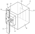
図1は実施の形態1における自走エレベーターの駆動装置が適用されるエレベーターシステムの構成図である。Embodiment 1.
FIG. 1 is a configuration diagram of an elevator system to which a self-propelled elevator drive device according to the first embodiment is applied.
図1のエレベーターシステムは、自走エレベーターのシステムである。自走エレベーターは、人、物等の搬送物を昇降方向に搬送する装置である。例えば、昇降方向は、鉛直方向である。例えば、昇降方向は、鉛直方向に対して傾いた斜めの方向である。 The elevator system in FIG. 1 is a self-propelled elevator system. A self-propelled elevator is a device that transports objects such as people and objects in an up-down direction. For example, the vertical direction is the vertical direction. For example, the ascending and descending direction is an oblique direction that is inclined with respect to the vertical direction.
自走式エレベーターは、かごを昇降させるためのロープを必要としない。このため、1つの昇降路において、複数台のかごを走行させることができる。ロープで駆動する一般のエレベーターを含めて、エレベーターが設けられる建築物が高層化するほど建築物に対して昇降路が占める割合は大きくなる。このため、1つの昇降路に複数台のかごを走行させることは、昇降路の水平投影面上の面積を削減するうえで有効である。 Self-propelled elevators do not require ropes to raise and lower the car. Therefore, a plurality of cars can run in one hoistway. The higher the building in which the elevator is installed, including general elevators driven by ropes, the larger the ratio of the hoistway to the building becomes. Therefore, having a plurality of cars run in one hoistway is effective in reducing the area on the horizontal projection plane of the hoistway.
例えば、エレベーター1は、建築物に設けられる。建築物は、複数の階床を有する。建築物において、昇降路2は、複数の階床にわたって設けられる。昇降路2は、昇降路2aと昇降路2bとに分割される。この例において、昇降方向は、鉛直方向である。
For example, the elevator 1 is installed in a building. A building has multiple floors. In a building, the
一対のレール3の一方は、昇降路2aにおいて長手方向を鉛直方向にして積み上げられる。一対のレール3の他方は、昇降路2bにおいて長手方向を鉛直方向にして積み上げられる。
One of the pair of
分割レール3aは、一対のレール3の一方の下方に配置される。分割レール3aは、図示されないアクチュエーターにより回転し得るように設けられる。分割レール3aは、長手方向を鉛直方向または水平方向とした際に姿勢を維持し得るように設けられる。
The divided
分割レール3bは、一対のレール3の一方の上方に配置される。分割レール3bは、図示されないアクチュエーターにより回転し得るように設けられる。分割レール3bは、長手方向を鉛直方向または水平方向とした際に姿勢を維持し得るように設けられる。
The divided
分割レール3cは、一対のレール3の他方の上方に配置される。分割レール3cは、図示されないアクチュエーターにより回転し得るように設けられる。分割レール3cは、長手方向を鉛直方向または水平方向とした際に姿勢を維持し得るように設けられる。
The divided
分割レール3dは、一対のレール3の他方の下方に配置される。分割レール3dは、図示されないアクチュエーターにより回転し得るように設けられる。分割レール3dは、長手方向を鉛直方向または水平方向とした際に姿勢を維持し得るように設けられる。
The divided
水平レール3eは、昇降路2の下部において長手方向を水平方向として配置される。水平レール3eは、昇降路2aの下部と昇降路2bの下部とにまたがって配置される。水平レール3eの一側は、分割レール3aが長手方向を水平方向とした際に分割レール3aと円滑につながり得るように設けられる。水平レール3eの他側は、分割レール3dが長手方向を水平方向とした際に分割レール3dと円滑につながり得るように設けられる。
The
水平レール3fは、昇降路2の上部において長手方向を水平方向として配置される。水平レール3fは、昇降路2aの上部と昇降路2bの上部とにまたがって配置される。水平レール3fの一側は、分割レール3bが長手方向を水平方向とした際に分割レール3bと円滑につながり得るように設けられる。水平レール3fの他側は、分割レール3cが長手方向を水平方向とした際に分割レール3cと円滑につながり得るように設けられる。
The
エレベーター1は、2台以上のかご4を備える。例えば、エレベーター1は、昇降路2aと昇降路2bとに対して3台以上のかご4を備えることもある。
The elevator 1 includes two or
かご4は、かご室5と駆動装置6と制御部7とを備える。
The
かご室5は、搬送物を搭載する空間を内部に有する。かご室5は、かご床8を有する。かご床8は、かご室5の下面である。かご床8は、かご室5に搭載される搬送物の荷重を支持する。
The
駆動装置6は、かご室5を昇降させる駆動力を発生させる装置である。駆動装置6は、利用者がかご室5に対して乗り降りする乗場とは反対側においてかご室5の背面側に設けられる。駆動装置6は、レール3を把持する。駆動装置6は、レール3との間の摩擦力によりかご室5を昇降させる。
The
制御部7は、かご4の動作を制御する部分である。例えば、制御部7は、かご室5の上部に配置される。例えば、制御部7は、かご4の下部に配置される。例えば、制御部7は、かご4において上部および下部以外の場所に配置される。例えば、制御部7は、複数の部分に分割されて配置される。
The
この例において、かご室5は、昇降路2aまたは昇降路2bを昇降する。かご室5は、昇降路2の上部または下部において昇降路2aと2bとの間を移動する。
In this example, the
例えば、かご室5は、昇降路2aにおいて駆動装置6を介してレール3に案内されて上昇することで分割レール3bに至る。その後、分割レール3bと分割レール3cとは、長手方向が鉛直方向から水平方向へとなるように90度回転する。その後、かご室5は、駆動装置6を介して分割レール3bに案内されて水平方向に移動する。その後、かご室5は、駆動装置6を介して水平レール3fに案内されて水平方向に移動する。その後、かご室5は、駆動装置6を介して分割レール3cに到着する。その後、分割レール3bと分割レール3cとは、長手方向が水平方向から鉛直方向へとなるように90度回転する。その後、かご室5は、昇降路2bにおいて駆動装置6を介して分割レール3cに案内されて下降することでレール3に至る。
For example, the
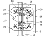
次に、図2を用いて、レール3とかご4とを説明する。
図2は実施の形態1における自走エレベーターの駆動装置が適用されるエレベーターシステムのレールとかごとを説明するための斜視図である。Next, the
FIG. 2 is a perspective view for explaining the rails and car of an elevator system to which the self-propelled elevator drive device according to the first embodiment is applied.
この例において、レール3の水平断面の形状は、T字形状である。レール3は、底板9およびガイド板10を有する。底板9は、かご4から遠い側の部分である。この例において、ガイド板10は、底板9に垂直な板である。ガイド板10は、底板9からかご4の側に配置される板状部分である。ガイド板10は、ガイド面11を有する。ガイド面11は、ガイド板10の表面または裏面の少なくとも一方である。ガイド面11は、レール3の長手方向に延びる。なお、レール3は、実際には上から下へ延伸しているが、図2においては、後述する駆動輪21、第1押付け力平均化リンク22、および第2押付け力平均化リンク23とレール3と駆動装置6との位置関係をわかりやすく説明するために、破断線(波線)で挟まれた領域において、レール3の図示は省略される。
In this example, the horizontal cross-sectional shape of the
図示されないが、分割レール3a等も、レール3と同等の構成である。
Although not shown, the
かご室5は、かごドア13を有する。かごドア13は、かご室5において駆動装置6とは反対側に設けられる。図示されないが、かご4は、駆動装置6の他に、ブレーキ、非常止め装置等を有することもある。ブレーキは、かご4の移動中または静止中に制動力を与え得るように設けられる。非常止め装置は、かご4が自由落下した際にかご4を強制的に静止させ得るように設けられる。
The
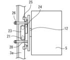
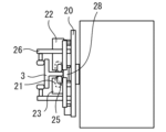
次に、図3から図6を用いて、駆動装置6を説明する。
図3は実施の形態1における自走エレベーターの駆動装置の背面図である。図4は実施の形態1における自走エレベーターの駆動装置の側面図である。図5は実施の形態1における自走エレベーターの駆動装置の背面図である。図6は実施の形態1における自走エレベーターの駆動装置の側面図である。Next, the
FIG. 3 is a rear view of the self-propelled elevator drive device in the first embodiment. FIG. 4 is a side view of the self-propelled elevator drive device in the first embodiment. FIG. 5 is a rear view of the self-propelled elevator drive device in the first embodiment. FIG. 6 is a side view of the self-propelled elevator drive device according to the first embodiment.
図3と図4とは、かご4が鉛直方向に移動する場合を示す。
3 and 4 show the case where the
ベアリング12は、かご室5の背面と駆動装置6とを連結する。分割レール3a等が回転する際、駆動装置6は、分割レール3a等とともに回転する。これに対し、かご室5は、静止して回転しない。その結果、かご室5の内部において、搬送物は、回転しない。
The
駆動装置6は、回転体として回転板20を有する。
The
回転板20は、ベアリング12を介してかご室5の背面に対して回転自在に連結される。
The rotating
駆動装置6は、一対の車輪と一対の駆動輪21とを有する。
The
一対の車輪の一方は、一対のガイド面11の一方に接触する。一対の駆動輪21の一方は、一対の車輪の一方の下方において一対のガイド面11の一方に接触する。一対の車輪の他方は、一対のガイド面11の他方に接触する。一対の駆動輪21の他方は、一対の車輪の下方において一対のガイド面11の他方に接触する。
One of the pair of wheels contacts one of the pair of guide surfaces 11. One of the pair of driving
一対の車輪の一方と他方とは、両方のガイド面11に対して対称な位置に配置される。一対の駆動輪21の一方と他方とは、両方のガイド面11に対して対称な位置に配置される。
One and the other of the pair of wheels are arranged at symmetrical positions with respect to both guide surfaces 11. One and the other of the pair of
図示されないが、駆動装置6は、駆動輪21を動かすために少なくとも1つのモーターを有する。
Although not shown, the
この例においては、第1押付け力平均化リンク22は、三角形状である。第1押付け力平均化リンク22は、車輪支持リンクとして、一対のガイド面11の一方の側に配置される。第1押付け力平均化リンク22は、一対の車輪の一方と一対の駆動輪21の一方とを回転自在に支持する。第1押付け力平均化リンク22において、レール3とは反対側の一端は、回転板20に対して回転自在に支持される。
In this example, the first pressing
この例においては、第2押付け力平均化リンク23は、四角形状である。第2押付け力平均化リンク23は、一対のガイド面11の他方の側に配置される。第2押付け力平均化リンク23は、車輪支持リンクとして、一対の車輪の他方と一対の駆動輪21の他方とを回転自在に支持する。第2押付け力平均化リンク23において、レール3とは反対側は、自己倍力用リンク24に対して回転自在に支持される。
In this example, the second pressing
自己倍力用リンク24は、水平方向に対して45度以下の角度で斜めに配置される。自己倍力用リンク24の一端は、第2押付け力平均化リンク23におけるレール3とは反対側に対して回転自在に連結される。自己倍力用リンク24の他端は、回転板20に対して回転自在に支持される。
The self-boosting
ばね29の一端は、第2押付け力平均化リンク23または自己倍力用リンク24に連結される。ばね29の他端は、回転板20に連結される。
One end of the
第1組の第1左右傾き防止ローラー25の一方は、一対の車輪の一方と一対の駆動輪21の一方との上方において一対のガイド面11の一方に接触する。第1組の第1左右傾き防止ローラー25の他方は、一対の車輪の一方と一対の駆動輪21の一方との下方において一対のガイド面11の一方に接触する。
One of the first left-right
第2組の第1左右傾き防止ローラー25の一方は、一対の車輪の他方と一対の駆動輪21の他方との上方において一対のガイド面11の他方に接触する。第2組の第1左右傾き防止ローラー25の他方は、一対の車輪の他方と一対の駆動輪21の他方との下方において一対のガイド面11の他方に接触する。
One of the first left-right
第1組のリンクの一方において、一端は、第1組の第1左右傾き防止ローラー25の一方を回転自在に支持する。第1組のリンクの一方において、他端は、回転板20に対して回転自在に支持される。第1組のリンクの他方において、一端は、第1組の第1左右傾き防止ローラー25の他方を回転自在に支持する。第1組のリンクの他方において、他端は、回転板20に対して回転自在に支持される。
One end of one of the first sets of links rotatably supports one of the first left-right
第2組のリンクの一方において、一端は、第2組の第1左右傾き防止ローラー25の一方を回転自在に支持する。第2組のリンクの一方において、他端は、回転板20に対して回転自在に支持される。第2組のリンクの他方において、一端は、第2組の第1左右傾き防止ローラー25の他方を回転自在に支持する。第2組のリンクの他方において、他端は、回転板20に対して回転自在に支持される。
One end of one of the links of the second set rotatably supports one of the first left-right
複数のばね27は、かご室5と回転板20とが左右に傾こうとした際の復元力を与える弾性体として機能する。
The plurality of
第1組のばね27の一方において、一端は、第1組のリンクの一方の中央部に連結される。第1組のばね27の一方において、他端は、回転板20に連結される。第1組のばね27の他方において、一端は、第1組のリンクの他方の中央部に連結される。第1組のばね27の他方において、他端は、回転板20に連結される。
One end of one of the first set of
第2組のばね27の一方において、一端は、第2組のリンクの一方の中央部に連結される。第2組のばね27の一方において、他端は、回転板20に連結される。第2組のばね27の他方において、一端は、第2組のリンクの他方の中央部に連結される。第2組のばね27の他方において、他端は、回転板20に連結される。
One end of one of the second set of
第1組の第1前後傾き防止ローラー26の一方は、一対のガイド面11の一方の側で高さ方向において第1押付け力平均化リンク22の上方に配置される。第1組の第1前後傾き防止ローラー26の一方は、レール3の底板9においてかご室5から遠い側に接触した状態でアームを介して回転板20に支持される。第1組の第1前後傾き防止ローラー26の他方は、一対のガイド面11の一方の側で高さ方向において第1押付け力平均化リンク22の下方に配置される。第1組の第1前後傾き防止ローラー26の他方は、レール3の底板9においてかご室5から近い側に接触した状態でアームを介して回転板20に支持される。
One of the first longitudinal
第2組の第1前後傾き防止ローラー26の一方は、一対のガイド面11の他方の側で高さ方向において第2押付け力平均化リンク23の上方に配置される。第2組の第1前後傾き防止ローラー26の一方は、レール3の底板9においてかご室5から遠い側に接触した状態でアームを介して回転板20に支持される。第2組の第1前後傾き防止ローラー26の他方は、一対のガイド面11の他方の側で高さ方向において第2押付け力平均化リンク23の下方に配置される。第2組の第1前後傾き防止ローラー26の他方は、レール3の底板9においてかご室5から近い側に接触した状態でアームを介して回転板20に支持される。
One of the first longitudinal
一対の第2前後傾き防止ローラー28の一方は、高さ方向において第1組の第1前後傾き防止ローラー26の一方と第2組の第1前後傾き防止ローラー26の一方との間に配置される。一対の第2前後傾き防止ローラー28の一方は、レール3のガイド板10の先端に接触した状態で回転板20に支持される。一対の第2前後傾き防止ローラー28の他方は、高さ方向において第1組の第1前後傾き防止ローラー26の他方と第2組の第1前後傾き防止ローラー26の他方との間に配置される。一対の第2前後傾き防止ローラー28の他方は、レール3のガイド板10の先端に接触した状態で回転板20に支持される。
One of the pair of second longitudinal
図5と図6とは、かご4が水平方向に移動する場合を示す。
5 and 6 show the case where the
図5と図6とに示されるように、駆動装置6は、図3と図4とに示された状態から第1押付け力平均化リンク22がレール3の上側になるように90度回転する。
As shown in FIGS. 5 and 6, the
この際、レール3の下方において、一対の車輪の他方と一対の駆動輪21の他方とは、ばね29の強さによっては、ガイド面11に接触しないこともある。レール3の上方において、一対の車輪の一方と一対の駆動輪21の一方とは、ガイド面11に接触する。
At this time, below the
一対の車輪の一方と一対の駆動輪21の一方とは、ガイド面11に接触する。一対の車輪の一方と一対の駆動輪21の一方とは、かご4と駆動装置6との自重を支持する。これらの自重は、レール3への押付け力として作用する。当該押付け力は、かご室5を水平方向に移動させる際の摩擦力を発生させる。一対の車輪の一方と一対の駆動輪21の一方とは、かご室5を水平方向に移動させる力を発生させる。
One of the pair of wheels and one of the pair of
なお、かご4が分割レール3a等に到着した場合、かご4は、回転しないように固定される。例えば、かご室5は、図示されないブレーキにより分割レール3a等に固定される。例えば、かご室5は、図示されないピン等により昇降路2に固定される。
Note that when the
この状態において、分割レール3a等は、長手方向が鉛直方向から水平方向になるように回転する。駆動装置6と回転板20とは、分割レール3aの回転に追従して回転する。その結果、自己倍力用リンク24による押付け力が減少する。最終的には、当該押付け力はゼロになる。
In this state, the divided
分割レール3a等の長手方向が水平方向から鉛直方向になるように分割レール3a等が回転した場合、第2押付け力平均化リンク23と自己倍力用リンク24とは、ばね29の復元力により定位置に戻る。
When the divided
以上で説明した実施の形態1によれば、一対の車輪と一対の駆動輪21とは、レール3のガイド面11を挟み込むように配置される。分割レール3a等が長手方向を鉛直方向としている際、一対の車輪と一対の駆動輪21とは、分割レール3a等との摩擦によりかご室5を鉛直方向に移動させる力を発生させる。分割レール3a等が長手方向を水平方向としている際、一対の車輪と一対の駆動輪21とは、分割レール3a等との摩擦によりかご室5を水平方向に移動させる力を発生させる。このため、一つの駆動装置6でかご室5aを鉛直方向と水平方向とに移動させることができる。その結果、駆動装置6を簡素かつ軽量にすることができる。また、かご室5の移動の際の振動および騒音を抑制することができる。
According to the first embodiment described above, the pair of wheels and the pair of
また、分割レール3a等が長手方向を水平方向にしている際、一対の車輪の他方と一対の駆動輪21の他方とは、ばね29の強さによっては、ガイド面11に接触しないこともある。レール3の上方において、一対の車輪の一方と一対の駆動輪21の一方とは、ガイド面11に接触する。一対の車輪の一方と一対の駆動輪21の一方とは、かご室5を水平方向に移動させる力を発生させる。このため、押付け力が発生する車輪のみを駆動することでエネルギーの消費を抑制することができる。
Furthermore, when the longitudinal direction of the
また、自己倍力用リンク24は、水平方向に対して45度以下の角度で斜めに配置される。このため、かご4と駆動装置6との自重を利用して、これらの自重以上の押付け力を得ることができる。
Moreover, the self-boosting
また、かご室5が鉛直方向に移動する際、自己倍力用リンク24により積載重量の増大に伴って、受動的に車輪と駆動輪21との押付け力が増大する。また、かご室5aが水平方向に移動する際、レール3のガイド面11の上方の側において、車輪と駆動輪21とがかご室5を支持する。このため、積載重量の増大に伴って、受動的に車輪および駆動輪21の押付け力が増大する。この際、常に最大積載重量時に必要な押付け力を発生させ続ける必要がない。このため、レール3、車輪、駆動輪21を無駄に摩耗させたり、積載重量を計測したうえで当該積載重量に応じた押付け力を能動的に発生させる油圧などのアクチュエーターを用いたりする必要がない。その結果、駆動装置6を簡素かつ軽量にすることができる。
Further, when the
また、駆動装置6は、複数の第1左右傾き防止ローラー25と複数の第1前後傾き防止ローラー26と複数の第2前後傾き防止ローラー28とを有する。このため、かご室5が鉛直方向または水平方向に移動する際にかご室5の内部において偏った荷重がかかっている場合でも、かご室5の傾きを抑制することができる。
Further, the
また、第1押付け力平均化リンク22は、回転板20に対して回転自在に支持される。このため、一対の車輪の一方と一対の駆動輪21の一方とに作用する押付け力を平均化することができる。
Further, the first pressing
また、第2押付け力平均化リンク23は、回転板20に対して回転自在に支持される。このため、一対の車輪の一方と一対の駆動輪21の一方とに作用する押付け力を平均化することができる。
Further, the second pressing
なお、かご4がレール3の継ぎ目部分、分割レール3a等とレール3との間等に発生する段差または隙間を通過する場合、第1押付け力平均化リンク22および第2押付け力平均化リンク23とは、回転板20に対して少し回転する。このため、車輪と駆動輪21とは、当該段差または当該隙間を容易に通過することができる。
Note that when the
なお、昇降路2の中間部でレール3を分割し、かご4が水平方向に移動できるようにしてもよい。
Note that the
なお、車輪と駆動輪21との組み合わせは、適宜変更してもよい。例えば、車輪が3個で駆動輪21が1個である場合、図3において、一対のガイド面11の一方の側で上側または下側に駆動輪21を配置してもよい。例えば、車輪が2個で駆動輪21が2個である場合、図3において、一対のガイド面11の一方の側に2個の駆動輪21を配置したり、一対のガイド面11の一方の側かつ下側と他方の側かつ下側とにそれぞれ1個の駆動輪を配置したりしてもよい。例えば、駆動輪21が4個である場合は、図3において、すべての位置に駆動輪21を配置すればよい。
Note that the combination of wheels and drive
次に、図7と図8とを用いて、第1変形例を説明する。
図7は実施の形態1における自走エレベーターの駆動装置の第1変形例の背面図である。図8は実施の形態1における自走エレベーターの駆動装置の第1変形例の側面図である。Next, a first modification will be described using FIGS. 7 and 8.
FIG. 7 is a rear view of a first modification of the self-propelled elevator drive device in the first embodiment. FIG. 8 is a side view of a first modification of the self-propelled elevator drive device in the first embodiment.
図7と図8とに示されるように、第1変形例において、第2押付け力平均化リンク23はない。車輪および駆動輪21の少なくとも一方は、自己倍力用リンク24のレール3の側の端部に直接的に回転自在に支持される。
As shown in FIGS. 7 and 8, in the first modification, the second pressing
以上で説明した第1変形例によれば、第2押付け力平均化リンク23はない。このため、駆動装置6をより少ない部品点数でより簡素にすることができる。その結果、駆動装置6のコストを抑制し、かつ、駆動装置6をより軽量にすることができる。
According to the first modification described above, the second pressing
次に、図9を用いて、第2変形例を説明する。
図9は実施の形態1における自走エレベーターの駆動装置の第2変形例の背面図である。Next, a second modification will be described using FIG. 9.
FIG. 9 is a rear view of a second modification of the self-propelled elevator drive device in the first embodiment.
図9に示されるように、第2変形例において、第1押付け力平均化リンク22はない。車輪および駆動輪21は、固定リンク30に支持される。固定リンク30は、回転板20に対して回転しない。
As shown in FIG. 9, in the second modification, there is no first pressing
以上で説明した第2変形例によれば、車輪および駆動輪21は、固定リンク30に支持される。このため、駆動装置6をより簡素にすることができる。その結果、駆動装置6のコストを抑制し、かつ、駆動装置6をより軽くすることができる。
According to the second modification described above, the wheels and drive
次に、図10を用いて、第3変形例を説明する。
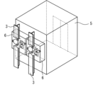
図10は実施の形態1における自走エレベーターの駆動装置の第3変形例の斜視図である。Next, a third modification will be described using FIG. 10.
FIG. 10 is a perspective view of a third modification of the self-propelled elevator drive device in the first embodiment.
図10に示されるように、かご4は、一対の駆動装置6を有する。一対の駆動装置6の一方は、一対のレール3の一方に案内される。一対の駆動装置6の他方は、一対のレール3の他方に案内される。
As shown in FIG. 10, the
以上で説明した第2変形例によれば、一対の駆動装置6の一方は、一対のレール3の一方に案内される。一対の駆動装置6の他方は、一対のレール3の他方に案内される。このため、個々のレール3と個々の駆動装置6とを小さくすることができる。その結果、昇降路2の水平投影面上の面積を小さくすることができる。
According to the second modification described above, one of the pair of
実施の形態2.
図11は実施の形態2における自走エレベーターの駆動装置が適用されるエレベーターシステムの下部を示す図である。図12は実施の形態2における自走エレベーターの駆動装置の背面図である。図13は実施の形態2における自走エレベーターの駆動装置の側面図である。図14は実施の形態2における自走エレベーターの駆動装置の背面図である。図15は実施の形態2における自走エレベーターの駆動装置の側面図である。なお、実施の形態1の部分と同一又は相当部分には同一符号が付される。当該部分の説明は省略される。
FIG. 11 is a diagram showing the lower part of an elevator system to which the self-propelled elevator drive device according to the second embodiment is applied. FIG. 12 is a rear view of the self-propelled elevator drive device in the second embodiment. FIG. 13 is a side view of a drive device for a self-propelled elevator according to the second embodiment. FIG. 14 is a rear view of the self-propelled elevator drive device according to the second embodiment. FIG. 15 is a side view of a drive device for a self-propelled elevator according to the second embodiment. Note that parts that are the same as or equivalent to those in Embodiment 1 are given the same reference numerals. Description of this part will be omitted.
図11に示されるように、分割レール3aは、上側分割レール3gと下側分割レール3hとに上下に分割される。上側分割レール3gと下側分割レール3hとは、それぞれ図示されないアクチュエーターにより回転し得るように設けられる。上側分割レール3gと下側分割レール3hとは、長手方向を鉛直方向または水平方向とした際に姿勢を維持し得るように設けられる。上側分割レール3gと下側分割レール3hとは、長手方向を鉛直方向とした際に互いに円滑につながり得るように設けられる。
As shown in FIG. 11, the divided
分割レール3dは、上側分割レール3iと下側分割レール3jとに上下に分割される。上側分割レール3iと下側分割レール3jとは、それぞれ図示されないアクチュエーターにより回転し得るように設けられる。上側分割レール3iと下側分割レール3jとは、長手方向を鉛直方向または水平方向とした際に姿勢を維持し得るように設けられる。上側分割レールと下側分割レールとは、長手方向を鉛直方向とした際に互いに円滑につながり得るように設けられる。
The divided
水平レール3eは、上側水平レール3kと下側水平レール3lとに上下に分割される。上側水平レール3kと下側水平レール3lとは、それぞれ長手方向を水平方向として配置される。
The
上側水平レール3kの一側は、上側分割レール3gが長手方向を水平方向とした際に上側分割レール3gと円滑につながり得るように設けられる。上側水平レール3kの他側は、上側分割レール3iが長手方向を水平方向とした際に上側分割レール3iと円滑につながり得るように設けられる。
One side of the upper
下側水平レール3lの一側は、下側分割レール3hが長手方向を水平方向とした際に下側分割レール3hと円滑につながり得るように設けられる。下側水平レール3lの他側は、下側分割レール3jが長手方向を水平方向とした際に下側分割レール3jと円滑につながり得るように設けられる。
One side of the lower horizontal rail 3l is provided so that it can be smoothly connected to the lower divided
図12等に示されるように、駆動装置6において、複数の分割体として、第2回転板31と第3回転板32とを有する。第2回転板31は、駆動装置6の上側に配置される。第3回転板32は、駆動装置6の下側に配置される。第2回転板31と第3回転板32とは、それぞれベアリング12を介してかご室5の背面に対して回転自在に連結される。
As shown in FIG. 12 and the like, the
第2回転板31は、第1押付け力平均化リンク22、第2押付け力平均化リンク23、自己倍力用リンク24、1個以上の駆動輪を含む車輪および駆動輪21を4つ、第1前後傾き防止ローラー26および少なくとも1つ以上のモーターを有する。
The second
第3回転板32は、第1左右傾き防止ローラー25と第2前後傾き防止ローラー28とを有する。
The third
かご室5は、鉛直方向に移動する際に1本のレールに案内される。かご室5は、水平方向に移動する際に2本のレールに案内される。具体的には、第2回転板31と第3回転板32それぞれに対し、1本のレールが必要となる。
The
例えば、図11でかご室5が昇降路2aの下部から昇降路2bに移動する場合、第2回転板31の側において、車輪および駆動輪21は、上側分割レール3g、上側水平レール3k、上側分割レール3iに沿って移動する。一方、第3回転板32の側において、第1左右傾き防止ローラー25と第2前後傾き防止ローラー28とは、下側分割レール3h、下側水平レール3l、下側分割レール3jを移動する。
For example, when the
具体的には、かご室5が上側分割レール3gと下側分割レール3hとに到着すると、かご室5は、回転しないように固定される。例えば、かご室5は、図示されないブレーキにより上側分割レール3gおよび下側分割レール3hの少なくとも一方に固定される。例えば、かご室5は、図示されないピン等により昇降路2に固定される。
Specifically, when the
この状態において、上側分割レール3gと下側分割レール3hとは、長手方向が鉛直方向から水平方向になるように回転する。第2回転板31は、上側分割レール3gの回転に追従して回転する。その結果、自己倍力用リンク24による押付け力が減少する。最終的には、当該押付け力はゼロになる。一方、第3回転板32は、下側分割レール3hの回転に追従して回転する。
In this state, the upper divided
この状態において、かご室5は、水平方向に移動する。その後、かご室5は、上側分割レール3iと下側分割レールと3jに到着すると、かご室5は、回転しないように固定される。例えば、かご室5は、図示されないブレーキにより上側分割レール3iおよび下側分割レール3jの少なくとも一方に固定される。例えば、かご室5は、図示されないピン等により昇降路2に固定される。
In this state, the
この状態において、上側分割レール3iと下側分割レール3jとは、長手方向が水平方向から鉛直方向になるように回転する。この際、第2押付け力平均化リンク23と自己倍力用リンク24とは、ばね29の復元力により定位置に戻る。
In this state, the upper divided rail 3i and the lower divided
以上で説明した実施の形態2によれば、第2回転板31は、駆動装置6の上側に配置される。第3回転板32は、駆動装置6の下側に配置される。このため、かご室5が鉛直方向または水平方向に移動する際に、かご室5の前後方向および水平方向に倒れることを抑制できる。
According to the second embodiment described above, the second
また、第2回転板31と第3回転板32との回転半径と質量とが減少する。回転半径と質量との減少により、第2回転板31と第3回転板32との回転時の慣性質量も減少する。このため、第2回転板31と第3回転板32とを回転させるために昇降路2に配置するアクチュエーターを小さくすることができる。その結果、昇降路2の水平投影面上の面積を削減することができる。
Moreover, the rotation radius and mass of the second
また、駆動装置6は、複数の第1左右傾き防止ローラー25と複数の第1前後傾き防止ローラー26と複数の第2前後傾き防止ローラー28とを有する。このため、かご室5が鉛直方向または水平方向に移動する際にかご室5の内部において偏った荷重がかかっている場合でも、かご室5の傾きを抑制することができる。
Further, the
実施の形態3.
図16は実施の形態3における自走エレベーターの駆動装置の斜視図である。なお、実施の形態1の部分と同一又は相当部分には同一符号が付される。当該部分の説明は省略される。
FIG. 16 is a perspective view of a drive device for a self-propelled elevator in
図16に示されるように、実施の形態3において、レール3は、実施の形態1のレール3を水平投影面上で90度回転させたように配置される。この場合、ガイド板10は、かごドア13の開閉方向と平行になる。
As shown in FIG. 16, in the third embodiment, the
次に、図17から図20を用いて、駆動装置6を説明する。
図17は実施の形態3における自走エレベーターの駆動装置の背面図である。図18は実施の形態3における自走エレベーターの駆動装置の側面図である。図19は実施の形態3における自走エレベーターの駆動装置の背面図である。図20は実施の形態3における自走エレベーターの駆動装置の側面図である。Next, the
FIG. 17 is a rear view of the self-propelled elevator drive device in
この例において、駆動装置6は、支持板43と一対の第1押付け力平均化リンク22とを有する。
In this example, the
支持板43は、支持体として回転板20と直交するように回転板20に固定される。
The
一対の第1押付け力平均化リンク22の一方は、かご室5から遠い側において一対のガイド面11の一方の側に配置される。一対の第1押付け力平均化リンク22の一方は、第1車輪支持リンクとして、一対の車輪の一方と一対の駆動輪21の一方とを回転自在に支持する。一対の第1押付け力平均化リンク22において、レール3とは反対側の一端は、支持板43に対して回転自在に支持される。
One of the pair of first pressing
一対の第1押付け力平均化リンク22の他方は、かご室5から近い側において一対のガイド面11の他方の側に配置される。一対の第1押付け力平均化リンク22の他方は、第2車輪支持リンクとして、一対の第1押付け力平均化リンク22の一方よりもhだけ低い位置に配置される。一対の第1押付け力平均化リンク22の他方は、一対の車輪の他方と一対の駆動輪21の他方とを回転自在に支持する。一対の第1押付け力平均化リンク22の他方において、レール3とは反対側の一端は、支持板43に対して回転自在に支持される。
The other of the pair of first pressing
第1組の複数の第2左右傾き防止ローラー41は、回転板20に設けられる。第1組の複数の第2左右傾き防止ローラー41は、レール3におけるかご室の側の底板9の一面に接触する。
The plurality of second left-right
第2組の複数の第2左右傾き防止ローラー41は、支持板43に設けられる。第2組の複数の第2左右傾き防止ローラー41は、レール3におけるかご室の側の底板9の他面に接触する。
The second set of the plurality of second left-right
例えば、第3前後傾き防止ローラー42は、かご室5から遠い側において最上部にある車輪または駆動輪21と同じ高さの位置に配置される。例えば、第3前後傾き防止ローラー42は、かご室5から遠い側において最上部にある車輪または駆動輪21よりも高い位置に配置される。第3前後傾き防止ローラー42は、レール3におけるかご室5から近い側のガイド面11に接触する。
For example, the third longitudinal
以上で説明した実施の形態3によれば、一対の第1押付け力平均化リンク22の他方は、第2車輪支持リンクとして、一対の第1押付け力平均化リンク22の一方よりもhだけ低い位置に配置される。このため、かご室5が倒れようとするモーメントを車輪および駆動輪21の押付け力として利用することができる。その結果、車輪および駆動輪21とレール3との間の摩擦により鉛直方向にかご室5を移動させるために必要な大きな押付け力を得ることができる。
According to the third embodiment described above, the other of the pair of first pressing
具体的には、図18に示されるように、かご室5と駆動装置6の合計質量Mが作用する重心がレール3から距離dだけ離れている場合、車輪および駆動輪21のそれぞれの押付け力がF/2であるとすると、モーメントの吊り合いにより、次式が成立する。なお、gは重力加速度である。
Specifically, as shown in FIG. 18, when the center of gravity on which the total mass M of the
F=Mg×(d/h) F=Mg×(d/h)
このため、d/hを適切に設定することにより、かご室5と駆動装置6との自重以上の押付け力を得ることができる。例えば、d/hが1である場合、かご室5と駆動装置6との自重と同じ押付け力を得ることができる。
Therefore, by appropriately setting d/h, it is possible to obtain a pressing force that is greater than the weight of the
また、当該押付け力は、かご室5と駆動装置6との合計質量Mに比例する。このため、かご室5の積載重量が増大した場合、受動的に車輪および駆動輪21の押付け力が増大する。この際、常に最大積載重量時に必要な押付け力を発生させ続ける必要がない。このため、レール3、車輪、駆動輪21を無駄に摩耗させたり、積載重量を計測したうえで当該積載重量に応じた押付け力を能動的に発生させる油圧などのアクチュエーターを用いたりする必要がない。その結果、駆動装置6を簡素かつ軽量にすることができる。
Further, the pressing force is proportional to the total mass M of the
図19と図20とに示されるように、かご室5を水平方向に移動する場合、かご室5が倒れようとするモーメントがかご室5から遠い側の第1押付け力平均化リンク22の車輪および駆動輪21に作用する。当該モーメントにより、レール3への押付け力が作用する。このため、かご室5から遠い側の駆動輪21のみを駆動させればよい。
As shown in FIGS. 19 and 20, when the
また、かご4の姿勢は、第1組の複数の第2左右傾き防止ローラー41と第2組の複数の第2左右傾き防止ローラー41と第3前後傾き防止ローラー42とで決まる。このため、かご室5の積載重量が偏っている場合でも、鉛直方向または水平方向にかご室5を移動させることができる。
Further, the attitude of the
また、第1押付け力平均化リンク22は、支持板43に対して回転自在に支持される。このため、車輪と駆動輪21とに作用する押付け力を平均化することができる。その結果、かご4がレール3の継ぎ目部分、分割レール3a等とレール3との間等に発生する段差または隙間を容易に通過することができる。
Further, the first pressing
なお、実施の形態3においては、実施の形態1よりも駆動装置6の奥行寸法が増大するものの、自己倍力用リンク24を削除することができる。このため、回転板20の寸法を小さくできる。その結果、駆動装置6を簡素にすることができる。
In addition, in
次に、図21を用いて、第1変形例を説明する。
図21は実施の形態3における自走エレベーターの駆動装置の第1変形例の側面図である。Next, a first modification will be described using FIG. 21.
FIG. 21 is a side view of a first modification of the self-propelled elevator drive device according to the third embodiment.
図21に示されるように、駆動装置6は、車輪と駆動輪21と一対の車輪固定リンク44とを有する。
As shown in FIG. 21, the
車輪は、かご4から近い側において一対のガイド面11の一方の側に配置される。駆動輪21は、かご4から遠い側において一対のガイド面11の他方の側に配置される。
The wheels are arranged on one side of the pair of guide surfaces 11 on the side closer to the
一対の車輪固定リンク44の一方は、かご4から遠い側において一対のガイド面11の一方の側に配置される。一対の車輪固定リンク44の一方は、駆動輪21を回転自在に支持する。一対の車輪固定リンク44の一方において、レール3とは反対側の一端は、支持板43に固定される。
One of the pair of
一対の車輪固定リンク44の他方は、かご4から近い側において一対のガイド面11の他方の側に配置される。一対の車輪固定リンク44の他方は、一対の車輪固定リンク44の一方よりも低い位置に配置される。一対の車輪固定リンク44の他方は、駆動輪21を回転自在に支持する。一対の車輪固定リンク44の他方において、レール3とは反対側の一端は、支持板43に固定される。
The other of the pair of
以上で説明した第1変形例によれば、駆動装置6は、車輪と駆動輪21と一対の車輪固定リンク44とを有する。このため、駆動装置6をより簡素かつより軽量にすることができる。
According to the first modification described above, the
実施の形態4.
図22は実施の形態4における自走エレベーターの駆動装置が適用されるエレベーターシステムの斜視図である。なお、実施の形態1の部分と同一又は相当部分には同一符号が付される。当該部分の説明は省略される。
FIG. 22 is a perspective view of an elevator system to which the self-propelled elevator drive device according to the fourth embodiment is applied. Note that parts that are the same as or equivalent to those in Embodiment 1 are given the same reference numerals. Description of this part will be omitted.
実施の形態4においては、水平方向への移動のために、長いレールが設けられる。当該レールは、互いに離れた位置に設けられた第1建築物と第2建築物とにまたがる。 In the fourth embodiment, long rails are provided for horizontal movement. The rail spans a first building and a second building that are located apart from each other.
次に、図23を用いて、かご4を説明する。
図23は実施の形態4における自走エレベーターのかごの斜視図である。Next, the
FIG. 23 is a perspective view of a self-propelled elevator car in
かご4が搬送機器51として使用される場合、荷物のみを運搬することが考慮される。この場合、かご室5は、天井を有さない。例えば、かご室5は、実施の形態1から実施の形態3のかご室5の壁の途中までの高さの壁または柵52を有する。
When the
以上で説明した実施の形態4によれば、かご4が搬送機器として使用される。この場合、かご室5の移動時の加速度を高くすることができる。このため、かご室5の鉛直方向と水平方向との移動を高速化することができる。その結果、図21に示されるような複数の建物の間において荷物を短時間で搬送することができる。
According to the fourth embodiment described above, the
なお、ホテル、大規模な施設群等の3つ以上の建築物の間において荷物を搬送できるようにしてもよい。 Note that it may also be possible to transport luggage between three or more buildings, such as a hotel or a large-scale facility group.
また、搬送機器としては、運搬ロボットも考えられる。運搬ロボットは、車輪により水平方向に自律移動する。運搬ロボットは、人と共働することを目的とする。このため、運搬ロボットは、人と接触しないように移動する。さらに、運搬ロボットは、人との接触時の衝撃を抑えるために低速で移動する。運搬ロボットは、任意の場所を移動できるものの、目的地近傍等の詳細な位置の把握が必要な場合により低速度で移動する。 Furthermore, a transportation robot can also be considered as the transportation device. The transportation robot moves autonomously in the horizontal direction using wheels. Transport robots are intended to work together with humans. Therefore, the transportation robot moves so as not to come into contact with people. Additionally, transport robots move at low speeds to reduce shock when they come into contact with people. Although transport robots can move anywhere, they move at low speeds when it is necessary to know the detailed location, such as in the vicinity of a destination.
これに対し、実施の形態4のエレベーターシステムにおいて、かご室5は、移動可能な場所が制限されるものの、専用の移動スペースとレールを有する。このため、運搬ロボットと比較して、より高速で移動することができる。また、かご室5の位置の把握等のために減速する必要をなくすことができる。
In contrast, in the elevator system of
次に、図24を用いて、第1変形例を説明する。
図24は実施の形態4における自走エレベーターの駆動装置が適用されるエレベーターシステムの要部の斜視図である。Next, a first modification will be described using FIG. 24.
FIG. 24 is a perspective view of a main part of an elevator system to which the self-propelled elevator drive device according to
図24は、倉庫の内部を示す。倉庫において、複数の棚62は、隣接して配置される。複数の棚62の各々において、複数の棚板63は、鉛直方向に並んで設けられる。複数の棚板63は、互いに平行である。荷物66は、棚板63に載せられた状態で保管される。
FIG. 24 shows the inside of the warehouse. In the warehouse,
複数のレール64は、複数の棚板63に対応して棚62の背面側に設けられる。複数のレール64のそれぞれは、複数の棚板63のそれぞれに対して平行に配置される。複数の分割レール65は、複数の棚62の両側に設けられる。図示されないが、横移動用レールは、最も下方に存在する分割レール65に隣接する。
The plurality of
搬送機器61は、荷受け部67を有する。搬送機器61は、レール64に案内されて対象の荷物66の位置まで移動する。その後、搬送機器61は、荷受け部67を前後に移動させて棚板63から当該荷物66を取り出す。その後、搬送機器61は、レール64と分割レール65と横移動用レールとに案内されて指定の場所まで荷物66を運搬する。
The
以上で説明した第1変形例によれば、レール3を固定する壁として棚62が利用される。このため、広大な倉庫であっても搬送機器61を利用することができる。
According to the first modification described above, the
同様な棚の配置において、荷物66を棚に置くまたは回収する機器としてスタッカークレーンがある。スタッカークレーンにおいて、車両部は、棚と棚の間に配置されたレールに沿って移動する。荷台は、車両部に設置された柱に沿って上下する。当該スタッカークレーンによれば、両側の棚と荷物の受け渡しができる。
In a similar shelving arrangement, a stacker crane is used as a device to shelve or retrieve
しかしながら、移動するレールごとに専用となる1台または少数台のスタッカークレーンが配置される。このため、同時に作業するスタッカークレーンの台数は限られる。 However, one or a few stacker cranes are dedicated to each rail to be moved. Therefore, the number of stacker cranes that can work at the same time is limited.
これに対し、多数の搬送機器61を投入することで、同時に作業する搬送機器61の台数を増やすことができる。その結果、効率的に荷物66を運搬することができる。
On the other hand, by introducing a large number of
以上のように、本開示の自走式エレベーターの駆動装置は、エレベーターシステムに利用できる。 As described above, the self-propelled elevator drive device of the present disclosure can be used in an elevator system.
1 エレベーター、 2 昇降路、 3 レール、 3a 分割レール、 3b 分割レール、 3c 分割レール、 3d 分割レール、 3e 水平レール、 3f 水平レール、 3g 上側分割レール、 3h 下側分割レール、 3i 上側分割レール、 3j 下側分割レール、 3k 上側水平レール、 3l 下側水平レール、 4 かご、 5 かご室、 6 駆動装置、 7 制御部、 8 かご床、 9 底板、 10 ガイド板、 11 ガイド面、 12 ベアリング、 13 かごドア、 20 回転板、 21 駆動輪、 22 第1押付け力平均化リンク、 23 第2押付け力平均化リンク、 24 自己倍力用リンク、 25 第1左右傾き防止ローラー、 26 第1前後傾き防止ローラー、 27 ばね、 28 第2前後傾き防止ローラー、 29 ばね、 30 固定リンク、 31 第2回転板、 32 第3回転板、 41 第2左右傾き防止ローラー、 42 第3前後傾き防止ローラー、 43 支持板、 44 車輪固定リンク、 51 搬送機器、 52 壁または柵、 61 搬送機器、 62 棚、 63 棚板、 64 レール、 65 分割レール、 66 荷物、 67 荷受け部 1 elevator, 2 hoistway, 3 rail, 3a split rail, 3b split rail, 3c split rail, 3d split rail, 3e horizontal rail, 3f horizontal rail, 3g upper split rail, 3h lower split rail, 3i upper split rail, 3j lower divided rail, 3k upper horizontal rail, 3l lower horizontal rail, 4 car, 5 car room, 6 drive device, 7 control section, 8 car floor, 9 bottom plate, 10 guide plate, 11 guide surface, 12 bearing, 13 car door, 20 rotary plate, 21 drive wheel, 22 first pressing force averaging link, 23 second pressing force averaging link, 24 self-boosting link, 25 first lateral tilt prevention roller, 26 first longitudinal tilt prevention roller, 27 spring, 28 second longitudinal tilt prevention roller, 29 spring, 30 fixed link, 31 second rotary plate, 32 third rotary plate, 41 second lateral tilt prevention roller, 42 third longitudinal tilt prevention roller, 43 Support plate, 44 Wheel fixing link, 51 Conveyance device, 52 Wall or fence, 61 Conveyance device, 62 Shelf, 63 Shelf board, 64 Rail, 65 Divided rail, 66 Luggage, 67 Load receiving section
Claims (10)
前記かご室の背面側においてレールのガイド面を挟み込むように前記回転体に設けられ、前記レールが長手方向を鉛直方向としている際に前記レールとの摩擦により前記かご室を鉛直方向に移動させる力を発生させ、前記レールが長手方向を水平方向としている際に前記レールとの摩擦力により前記かご室を水平方向に移動させる力を発生させる車輪と、
前記レールのガイド面に接触した第1左右傾き防止ローラーと、
前記回転体に回転自在に支持され、前記第1左右傾き防止ローラーを回転自在に支持したリンクと、
前記リンクと前記回転体とに連結された弾性体と、
前記レールの底板において前記かご室から遠い側に接触した状態で前記回転体に支持された第1前後傾き防止ローラーと、
前記レールのガイド板の先端に接触した状態で前記回転体に支持された第2前後傾き防止ローラーと、
を備えた搬送機器。 a rotating body rotatably connected to the back of the car;
A force that is provided on the rotating body so as to sandwich the guide surface of the rail on the rear side of the car, and that moves the car in the vertical direction due to friction with the rail when the longitudinal direction of the rail is vertical. a wheel that generates a force that moves the cage in the horizontal direction by frictional force with the rail when the longitudinal direction of the rail is horizontal;
a first left-right tilt prevention roller in contact with a guide surface of the rail;
a link rotatably supported by the rotating body and rotatably supporting the first left-right tilt prevention roller;
an elastic body connected to the link and the rotating body;
a first longitudinal inclination prevention roller supported by the rotary body while being in contact with a side of the bottom plate of the rail that is far from the car compartment;
a second longitudinal tilt prevention roller supported by the rotary body while in contact with the tip of the guide plate of the rail;
Conveyance equipment equipped with
前記かご室の背面側においてレールのガイド面を挟み込むように前記回転体に設けられ、前記レールが長手方向を鉛直方向としている際に前記レールとの摩擦により前記かご室を鉛直方向に移動させる力を発生させ、前記レールが長手方向を水平方向としている際に前記レールとの摩擦力により前記かご室を水平方向に移動させる力を発生させる車輪と、
前記レールのガイド面に接触した第1左右傾き防止ローラーと、
前記レールの底板において前記かご室から遠い側に接触した状態で前記一対の分割体の一方に支持された第1前後傾き防止ローラーと、
前記レールのガイド板の先端に接触した状態で前記一対の分割体の他方に支持された第2前後傾き防止ローラーと、
前記回転体の前記一対の分割体の他方に回転自在に支持され、前記第1左右傾き防止ローラーを回転自在に支持したリンクと、
前記リンクと前記回転体の前記一対の分割体の他方とに連結された弾性体と、
を備えた搬送機器。 a rotating body composed of a pair of divided bodies, each of which is rotatably connected to the back of the car;
A force that is provided on the rotating body so as to sandwich the guide surface of the rail on the back side of the car, and that moves the car in the vertical direction due to friction with the rail when the longitudinal direction of the rail is vertical. a wheel that generates a force that moves the car in the horizontal direction by frictional force with the rail when the longitudinal direction of the rail is horizontal;
a first left-right tilt prevention roller in contact with a guide surface of the rail;
a first longitudinal tilt prevention roller supported by one of the pair of divided bodies in contact with a side of the bottom plate of the rail that is far from the car compartment;
a second longitudinal tilt prevention roller supported by the other of the pair of divided bodies in contact with the tip of the guide plate of the rail;
a link that is rotatably supported by the other of the pair of divided bodies of the rotating body and rotatably supports the first left-right tilt prevention roller;
an elastic body connected to the link and the other of the pair of divided bodies of the rotating body;
Conveyance equipment equipped with
複数の車輪のうちの一部は、前記レールのガイド面の他方の側に設けられ、
前記複数の車輪のうちの他部は、前記レールのガイド面の一方の側に設けられ、前記レールが長手方向を水平方向としている際に前記ガイド面の一方に接触して前記レールとの摩擦力により前記かご室を水平方向に移動させる力を発生させる請求項1または請求項2に記載の搬送機器。 the wheels are plural;
Some of the plurality of wheels are provided on the other side of the guide surface of the rail,
The other part of the plurality of wheels is provided on one side of the guide surface of the rail, and when the longitudinal direction of the rail is horizontal, the other part contacts one of the guide surfaces and generates friction with the rail. The conveying device according to claim 1 or 2, wherein a force is generated to move the car in a horizontal direction.
前記かご室が鉛直方向に移動する際に水平方向に対して45度以下の角度で斜めに配置されるように前記レールのガイド面の他方の側において前記回転体に支持され、前記複数の車輪のうちの一部を回転自在に支持した自己倍力用リンクと、
を備えた請求項3に記載の搬送機器。 a wheel support link that is supported by the rotating body on one side of the guide surface of the rail and rotatably supports the other part of the plurality of wheels;
The plurality of wheels are supported by the rotating body on the other side of the guide surface of the rail so as to be arranged obliquely at an angle of 45 degrees or less with respect to the horizontal direction when the car moves vertically. A self-boosting link that rotatably supports a part of the link,
The conveying device according to claim 3 , comprising:
を備えた請求項4に記載の搬送機器。 a link that rotatably supports a portion of the plurality of wheels and is rotatably supported by the self-boosting link;
The conveying device according to claim 4 , comprising:
前記かご室の背面側においてレールのガイド面の一方の側に設けられた第1車輪と前記レールのガイド面の他方の側に設けられた第2車輪とで前記レールのガイド面を挟み込むように前記回転体に設けられ、前記レールが長手方向を鉛直方向としている際に前記レールとの摩擦により前記かご室を鉛直方向に移動させる力を発生させ、前記レールが長手方向を水平方向としている際に前記ガイド面の一方に接触して前記レールとの摩擦力により前記かご室を水平方向に移動させる力を発生させる車輪と、
前記回転体から前記かご室に対して離れる方向に伸びた支持体と、
前記レールに対して前記かご室から遠い側のガイド面の側において前記支持体に設けられ、前記第1車輪を回転自在に支持した第1車輪支持リンクと、
前記レールが長手方向を鉛直方向としている際に第1車輪支持リンクよりも低い位置に配置されるように、前記レールに対して前記かご室から近い側のガイド面の側において前記支持体に設けられ、前記第2車輪を回転自在に支持した第2車輪支持リンクと、
を備え、
前記かご室が水平方向に移動する場合は、前記第1車輪支持リンクの側の車輪が駆動される、搬送機器。 a rotating body rotatably connected to the back of the car;
The guide surface of the rail is sandwiched between a first wheel provided on one side of the guide surface of the rail and a second wheel provided on the other side of the guide surface of the rail on the rear side of the car compartment. Provided on the rotating body, when the rail has a longitudinal direction in a vertical direction, it generates a force that moves the car chamber in the vertical direction due to friction with the rail, and when the rail has a longitudinal direction in a horizontal direction, a wheel that comes into contact with one of the guide surfaces and generates a force that moves the car in a horizontal direction due to frictional force with the rail;
a support extending in a direction away from the rotating body with respect to the cage;
a first wheel support link that is provided on the support body on the side of the guide surface remote from the car with respect to the rail, and rotatably supports the first wheel ;
Provided on the support body on the side of the guide surface closer to the car compartment with respect to the rail so that the rail is disposed at a lower position than the first wheel support link when the longitudinal direction is the vertical direction. a second wheel support link rotatably supporting the second wheel;
Equipped with
When the cab moves in a horizontal direction, the wheels on the side of the first wheel support link are driven .
前記支持体に設けられ、前記レールにおけるかご室の側の底板の他面に接触する第2組の複数の第2左右傾き防止ローラーと、
前記かご室から遠い側において最上部にある車輪と同じ高さの位置またはかご室から遠い側において最上部にある車輪よりも高い位置において前記支持体に設けられ、前記レールにおける前記かご室から近い側のガイド面に接触する第3前後傾き防止ローラーと、
を備えた請求項8または請求項9に記載の搬送機器。 a first set of a plurality of second left-right tilt prevention rollers provided on the support and in contact with one surface of the bottom plate on the car room side of the rail;
a second set of second left-right tilt prevention rollers provided on the support body and in contact with the other surface of the bottom plate on the side of the car compartment of the rail;
Provided on the support body at a position at the same height as the top wheel on the side far from the car or at a position higher than the top wheel on the side far from the car, and close to the car on the rail a third longitudinal tilt prevention roller that contacts the side guide surface;
The conveying device according to claim 8 or 9 , comprising:
Applications Claiming Priority (1)
| Application Number | Priority Date | Filing Date | Title |
|---|---|---|---|
| PCT/JP2021/009051 WO2022190179A1 (en) | 2021-03-08 | 2021-03-08 | Drive device for self-propelled elevator |
Publications (3)
| Publication Number | Publication Date |
|---|---|
| JPWO2022190179A1 JPWO2022190179A1 (en) | 2022-09-15 |
| JPWO2022190179A5 JPWO2022190179A5 (en) | 2023-06-19 |
| JP7409552B2 true JP7409552B2 (en) | 2024-01-09 |
Family
ID=83227538
Family Applications (1)
| Application Number | Title | Priority Date | Filing Date |
|---|---|---|---|
| JP2023504896A Active JP7409552B2 (en) | 2021-03-08 | 2021-03-08 | Conveyance equipment |
Country Status (5)
| Country | Link |
|---|---|
| US (1) | US12503340B2 (en) |
| JP (1) | JP7409552B2 (en) |
| CN (1) | CN116963986A (en) |
| DE (1) | DE112021007262T5 (en) |
| WO (1) | WO2022190179A1 (en) |
Families Citing this family (2)
| Publication number | Priority date | Publication date | Assignee | Title |
|---|---|---|---|---|
| CN113879941B (en) * | 2021-09-24 | 2023-05-05 | 中际联合(北京)科技股份有限公司 | Modular lifting equipment and lifting system |
| CN119968333A (en) * | 2022-10-12 | 2025-05-09 | 三菱电机株式会社 | Self-propelled elevator and path switching method of self-propelled elevator |
Citations (7)
| Publication number | Priority date | Publication date | Assignee | Title |
|---|---|---|---|---|
| US4015537A (en) | 1975-06-09 | 1977-04-05 | Diebold, Incorporated | Interior railway transportation system |
| JP2001080848A (en) | 1999-09-10 | 2001-03-27 | Fujitec Co Ltd | Self-traveling type elevator |
| US20050236945A1 (en) | 2004-04-21 | 2005-10-27 | Vasco De Sousa Marreiros Alves | People and cargo transportation machine |
| US20070272494A1 (en) | 2006-05-24 | 2007-11-29 | Hans Kocher | Elevator with frictional drive |
| WO2018142556A1 (en) | 2017-02-03 | 2018-08-09 | 株式会社日立製作所 | Multi-car elevator |
| US20200131001A1 (en) | 2017-06-21 | 2020-04-30 | Thyssenkrupp Elevator Ag | Supporting device for a rotary platform in an elevator system |
| WO2021038731A1 (en) | 2019-08-27 | 2021-03-04 | 三菱電機株式会社 | Conveying device |
Family Cites Families (20)
| Publication number | Priority date | Publication date | Assignee | Title |
|---|---|---|---|---|
| US3261303A (en) * | 1964-07-10 | 1966-07-19 | Anglo Transvaal Cons Invest Co | Overhead haulage systems |
| DE1580860C3 (en) * | 1966-11-08 | 1980-04-17 | Pank Ag, Zuerich (Schweiz) | Overhead trolley |
| US3568605A (en) * | 1968-01-24 | 1971-03-09 | Projects General Of America | Suspended monorail system |
| DE1928058B2 (en) * | 1969-06-02 | 1974-11-14 | Von Roll Ag, Gerlafingen (Schweiz) | Transport unit for monorail suspension systems |
| US3658155A (en) * | 1970-09-15 | 1972-04-25 | William G Salter | Elevator system |
| US3774548A (en) * | 1971-01-13 | 1973-11-27 | A Borst | Gripping locomotive for suspended railway |
| DE68920795T2 (en) * | 1988-08-10 | 1995-05-18 | Yamaha Motor Co Ltd | Transport device. |
| DE4122855A1 (en) * | 1991-02-14 | 1992-08-20 | Hillenkoetter & Ronsieck | ELEVATOR, ESPECIALLY SLOPE ELEVATOR |
| JPH0648672A (en) | 1991-10-28 | 1994-02-22 | Toshiba Corp | Elevator |
| JP2987020B2 (en) * | 1992-12-25 | 1999-12-06 | 株式会社竹中工務店 | Elevator equipment |
| EP0745553A1 (en) * | 1995-06-02 | 1996-12-04 | Inventio Ag | Lift driving unit |
| EP0870718B1 (en) * | 1997-04-11 | 2003-06-25 | Inventio Ag | Gripping device for anchoring a lift cabin |
| AR018972A1 (en) * | 2000-01-13 | 2001-12-12 | Serrano Jorge | AUTONOMOUS TRANSPORTATION PROVISION AND AUTONOMOUS TRANSPORT VEHICLE. |
| JP2009280313A (en) * | 2008-05-20 | 2009-12-03 | Mitsubishi Electric Corp | Car device of self-propelled elevator |
| DE102014104458A1 (en) | 2014-03-28 | 2015-10-01 | Thyssenkrupp Elevator Ag | elevator system |
| SE1551010A1 (en) * | 2015-07-10 | 2017-01-11 | Articulated Funiculator Ab | Elevator carriage support structure |
| KR20180053047A (en) | 2016-11-11 | 2018-05-21 | 유장욱 | Circulation type elevator system |
| CA3092640A1 (en) * | 2018-06-14 | 2019-12-19 | Inventio Ag | Method for erecting a lift facility |
| CN112311099B (en) * | 2019-07-31 | 2023-08-18 | 湖南大举信息科技有限公司 | Power supply systems for elevators without accompanying cables and multi-car elevator systems |
| US20220177273A1 (en) * | 2020-12-04 | 2022-06-09 | Otis Elevator Company | Autonomous elevator car mover configured for derailment prevention |
-
2021
- 2021-03-08 US US18/278,183 patent/US12503340B2/en active Active
- 2021-03-08 WO PCT/JP2021/009051 patent/WO2022190179A1/en not_active Ceased
- 2021-03-08 JP JP2023504896A patent/JP7409552B2/en active Active
- 2021-03-08 DE DE112021007262.5T patent/DE112021007262T5/en active Pending
- 2021-03-08 CN CN202180095070.8A patent/CN116963986A/en active Pending
Patent Citations (7)
| Publication number | Priority date | Publication date | Assignee | Title |
|---|---|---|---|---|
| US4015537A (en) | 1975-06-09 | 1977-04-05 | Diebold, Incorporated | Interior railway transportation system |
| JP2001080848A (en) | 1999-09-10 | 2001-03-27 | Fujitec Co Ltd | Self-traveling type elevator |
| US20050236945A1 (en) | 2004-04-21 | 2005-10-27 | Vasco De Sousa Marreiros Alves | People and cargo transportation machine |
| US20070272494A1 (en) | 2006-05-24 | 2007-11-29 | Hans Kocher | Elevator with frictional drive |
| WO2018142556A1 (en) | 2017-02-03 | 2018-08-09 | 株式会社日立製作所 | Multi-car elevator |
| US20200131001A1 (en) | 2017-06-21 | 2020-04-30 | Thyssenkrupp Elevator Ag | Supporting device for a rotary platform in an elevator system |
| WO2021038731A1 (en) | 2019-08-27 | 2021-03-04 | 三菱電機株式会社 | Conveying device |
Also Published As
| Publication number | Publication date |
|---|---|
| DE112021007262T5 (en) | 2023-12-28 |
| US12503340B2 (en) | 2025-12-23 |
| WO2022190179A1 (en) | 2022-09-15 |
| US20240140760A1 (en) | 2024-05-02 |
| JPWO2022190179A1 (en) | 2022-09-15 |
| CN116963986A (en) | 2023-10-27 |
Similar Documents
| Publication | Publication Date | Title |
|---|---|---|
| US6443266B2 (en) | Traction type elevator | |
| JP7156545B2 (en) | Conveyor | |
| JP7409552B2 (en) | Conveyance equipment | |
| JP4543868B2 (en) | Multi car elevator | |
| US20260116662A1 (en) | Automated storage system comprising a shuttle for transporting storage aids | |
| US5816368A (en) | Elevator cars switch hoistways while traveling vertically | |
| CN111204623A (en) | Elevator system | |
| JPH11217950A (en) | Turn table equipment of parking facility | |
| KR102330511B1 (en) | Ropeless elevator system | |
| KR20180053047A (en) | Circulation type elevator system | |
| CN113581976B (en) | Guiding device for elevator car and elevator system | |
| JPH04191282A (en) | Elevator | |
| JPWO2007020674A1 (en) | Elevator equipment | |
| CN120057686B (en) | Elevator system | |
| KR102946385B1 (en) | Cantilever cargo lift for ships | |
| EP4337584B1 (en) | An elevator system and method | |
| JP7537977B2 (en) | Automated Warehouse System | |
| JP5676556B2 (en) | Elevator equipment | |
| JP2975308B2 (en) | Moving shelf | |
| WO2018142556A1 (en) | Multi-car elevator | |
| JP2024124711A (en) | Passenger conveyor and its supporting device | |
| JP6662472B2 (en) | Stacker crane | |
| JP2001140489A (en) | Parking facility equipped with traveling carriage | |
| KR20240025278A (en) | Transfer robot | |
| JP3051005U (en) | Lift with sliding carrier |
Legal Events
| Date | Code | Title | Description |
|---|---|---|---|
| A521 | Request for written amendment filed |
Free format text: JAPANESE INTERMEDIATE CODE: A523 Effective date: 20230330 |
|
| A621 | Written request for application examination |
Free format text: JAPANESE INTERMEDIATE CODE: A621 Effective date: 20230330 |
|
| TRDD | Decision of grant or rejection written | ||
| A01 | Written decision to grant a patent or to grant a registration (utility model) |
Free format text: JAPANESE INTERMEDIATE CODE: A01 Effective date: 20231121 |
|
| A61 | First payment of annual fees (during grant procedure) |
Free format text: JAPANESE INTERMEDIATE CODE: A61 Effective date: 20231204 |
|
| R150 | Certificate of patent or registration of utility model |
Ref document number: 7409552 Country of ref document: JP Free format text: JAPANESE INTERMEDIATE CODE: R150 |
|
| S533 | Written request for registration of change of name |
Free format text: JAPANESE INTERMEDIATE CODE: R313533 |
|
| R350 | Written notification of registration of transfer |
Free format text: JAPANESE INTERMEDIATE CODE: R350 |