JP7402006B2 - actuator - Google Patents
actuator Download PDFInfo
- Publication number
- JP7402006B2 JP7402006B2 JP2019179721A JP2019179721A JP7402006B2 JP 7402006 B2 JP7402006 B2 JP 7402006B2 JP 2019179721 A JP2019179721 A JP 2019179721A JP 2019179721 A JP2019179721 A JP 2019179721A JP 7402006 B2 JP7402006 B2 JP 7402006B2
- Authority
- JP
- Japan
- Prior art keywords
- movable body
- yoke
- coil
- pair
- support
- Prior art date
- Legal status (The legal status is an assumption and is not a legal conclusion. Google has not performed a legal analysis and makes no representation as to the accuracy of the status listed.)
- Active
Links
- 230000035807 sensation Effects 0.000 claims description 2
- BGPVFRJUHWVFKM-UHFFFAOYSA-N N1=C2C=CC=CC2=[N+]([O-])C1(CC1)CCC21N=C1C=CC=CC1=[N+]2[O-] Chemical compound N1=C2C=CC=CC2=[N+]([O-])C1(CC1)CCC21N=C1C=CC=CC1=[N+]2[O-] BGPVFRJUHWVFKM-UHFFFAOYSA-N 0.000 description 17
- 230000001133 acceleration Effects 0.000 description 3
- 239000000853 adhesive Substances 0.000 description 3
- 230000001070 adhesive effect Effects 0.000 description 3
- 239000000463 material Substances 0.000 description 3
- 238000010008 shearing Methods 0.000 description 3
- 238000003466 welding Methods 0.000 description 3
- 230000008602 contraction Effects 0.000 description 2
- 238000010586 diagram Methods 0.000 description 2
- 229920003244 diene elastomer Polymers 0.000 description 2
- 230000006870 function Effects 0.000 description 2
- 230000010287 polarization Effects 0.000 description 2
- 229920001296 polysiloxane Polymers 0.000 description 2
- 229920002943 EPDM rubber Polymers 0.000 description 1
- 229920000181 Ethylene propylene rubber Polymers 0.000 description 1
- 244000043261 Hevea brasiliensis Species 0.000 description 1
- 229920000459 Nitrile rubber Polymers 0.000 description 1
- 239000005062 Polybutadiene Substances 0.000 description 1
- 229920006311 Urethane elastomer Polymers 0.000 description 1
- 229920005549 butyl rubber Polymers 0.000 description 1
- 230000000694 effects Effects 0.000 description 1
- 229920001971 elastomer Polymers 0.000 description 1
- -1 etc.) Polymers 0.000 description 1
- 229920001973 fluoroelastomer Polymers 0.000 description 1
- 229920003049 isoprene rubber Polymers 0.000 description 1
- 239000000696 magnetic material Substances 0.000 description 1
- 238000000034 method Methods 0.000 description 1
- 229920003052 natural elastomer Polymers 0.000 description 1
- 229920001194 natural rubber Polymers 0.000 description 1
- CLNYHERYALISIR-UHFFFAOYSA-N nona-1,3-diene Chemical compound CCCCCC=CC=C CLNYHERYALISIR-UHFFFAOYSA-N 0.000 description 1
- 230000000149 penetrating effect Effects 0.000 description 1
- 229920001084 poly(chloroprene) Polymers 0.000 description 1
- 229920002857 polybutadiene Polymers 0.000 description 1
- 239000011347 resin Substances 0.000 description 1
- 229920005989 resin Polymers 0.000 description 1
- 239000005060 rubber Substances 0.000 description 1
- 229920002379 silicone rubber Polymers 0.000 description 1
- 239000004945 silicone rubber Substances 0.000 description 1
- 229920003048 styrene butadiene rubber Polymers 0.000 description 1
- 229920002725 thermoplastic elastomer Polymers 0.000 description 1
Images


Description
本発明は、可動体を振動させるアクチュエータおよび触覚デバイスに関する。 The present invention relates to an actuator and a haptic device that vibrate a movable body.
磁気駆動機構によって振動を発生させる機器として、第1方向で対向するコイルおよび磁石を備えた磁気駆動回路によって可動体を支持体に対して第1方向に対して交差する第2方向または第3方向に振動させるアクチュエータが提案されている。例えば、特許文献1に記載のアクチュエータにおいて、可動体はヨークを有し、ヨークには磁石が保持されている。支持体は、ホルダを有し、ホルダにはコイルが配置されている。磁気駆動機構は、磁石およびコイルで構成され、コイルへ給電されることで、磁気駆動機構が可動体を駆動する。このコイルは、直線部分と曲線部分とからなる長円形であり、直線部分は第2方向に沿って延在している。
As a device that generates vibrations using a magnetic drive mechanism, a magnetic drive circuit including a coil and a magnet facing each other in the first direction moves the movable body relative to the support in a second or third direction that intersects with the first direction. An actuator that vibrates has been proposed. For example, in the actuator described in
近年では、アクチュエータによって振動を発生させる機器をユーザが使用した際、ユーザが感じる振動の大きさがより大きいことが望まれており、それには、アクチュエータの振動を発生させる磁気駆動機構において、可動体が移動する距離を大きくすることも重要となる。この可動体の移動距離(移動量)は、コイルの大きさや磁石の磁力の大きさ等に依存するため、たとえば、コイルを大きくする場合は、コイルの長手方向が長くなるため、アクチュエータが大きくなるという問題がある。 In recent years, when a user uses a device that generates vibrations using an actuator, it is desired that the magnitude of the vibration that the user feels will be larger. It is also important to increase the distance traveled. The moving distance (travel amount) of this movable body depends on the size of the coil and the magnitude of the magnetic force of the magnet, so for example, if the coil is made larger, the longitudinal direction of the coil will be longer, so the actuator will be larger. There is a problem.
以上の問題に鑑みて、本願発明の課題は、アクチュエータおよび触覚デバイスを大きくすることなく、可動体の移動距離を大きく確保することにある。 In view of the above problems, an object of the present invention is to ensure a large moving distance of the movable body without increasing the size of the actuator and the tactile device.
上記課題を解決するために、本発明のアクチュエータは、支持体と、可動体と、前記支持体および前記可動体に接続された接続体と、前記支持体および前記可動体の一方側に配置された磁石と、前記支持体および前記可動体の他方側に配置されるとともに、第1方向で前記磁石と対向するコイルとを有する磁気駆動回路とを備え、前記支持体は、前記第1方向と直交する第2方向において対向する一対の第1側辺部と、前記第1方向および前記第2方向に対して直交する第3方向において対向する一対の第2側辺部と、を有し、前記コイルは、前記第1方向から見たときに、前記第2方向および前記第3方向に対して斜めに交差する第4方向と直交する第5方向に延在する長円形であり、前記磁石は前記第4方向に着磁され、前記磁気駆動回路は、前記可動体を前記支持体に対して前記第4方向に駆動することを特徴とする。 In order to solve the above problems, the actuator of the present invention includes a support body, a movable body, a connection body connected to the support body and the movable body, and a body disposed on one side of the support body and the movable body. a magnetic drive circuit having a coil disposed on the other side of the support body and the movable body and facing the magnet in a first direction, and the support body is arranged on the other side of the support body and the movable body. A pair of first side portions facing each other in a second orthogonal direction, and a pair of second side portions facing each other in a third direction orthogonal to the first direction and the second direction, The coil has an oval shape extending in a fifth direction perpendicular to a fourth direction diagonally intersecting the second direction and the third direction when viewed from the first direction, and the coil is magnetized in the fourth direction, and the magnetic drive circuit drives the movable body in the fourth direction with respect to the support body.
本発明では、支持体は、第1方向と直交する第2方向において対向する一対の第1側辺部と、第1方向と直交するとともに第2方向と交差する第3方向において対向する一対の第2側辺部とを有し、磁気駆動回路は、可動体を支持体に対し、第2方向および第3方向とは異なる第4方向に駆動し、コイルは、第4方向に直交する第5方向に延びる長円形であり、磁石は、第4方向に着磁されている。したがって、このアクチュエータにおいては、磁気駆動回路が第4方向に駆動するため、可動体の移動距離(移動量)を大きく確保す
ることができる。
In the present invention, the support has a pair of first side portions facing each other in a second direction perpendicular to the first direction, and a pair of first side portions facing each other in a third direction perpendicular to the first direction and intersecting the second direction. the magnetic drive circuit drives the movable body relative to the support in a fourth direction different from the second direction and the third direction; It has an oval shape extending in five directions, and the magnet is magnetized in the fourth direction. Therefore, in this actuator, since the magnetic drive circuit drives in the fourth direction, a large moving distance (moving amount) of the movable body can be ensured.
本発明において、前記コイルは、前記第1方向から見たときに前記第5方向に延在する直線部分を有し、前記磁石は、前記第1方向から見たときに前記コイルの前記直線部分の少なくとも一部と重なることが好ましい。このようにすれば、磁気駆動回路が発生させる第4方向への駆動力を効率的に大きくすることができる。 In the present invention, the coil has a linear portion extending in the fifth direction when viewed from the first direction, and the magnet has a linear portion of the coil when viewed from the first direction. It is preferable that at least a portion of the In this way, the driving force in the fourth direction generated by the magnetic drive circuit can be efficiently increased.
本発明において、前記接続体は、弾性体または粘弾性体であり、前記第2方向および前記第3方向の少なくともいずれか一方において前記支持体と前記可動体との間に配置される態様を採用することができる。 In the present invention, the connecting body is an elastic body or a viscoelastic body, and is arranged between the support body and the movable body in at least one of the second direction and the third direction. can do.
本発明において、前記接続体は、前記可動体が前記支持体に対して前記第2方向に振動する第1振動系を構成し、かつ、前記可動体が前記支持体に対して前記第3方向に振動する第2振動系を構成し、前記第1振動系の共振周波数と、前記第2振動系の共振周波数とが異なることが好ましい。このようにすれば、可動体が第2方向に振動する際と、第3方向に振動する際とでは、可動体を振動させる振動系の共振周波数が異なる。したがって、接続体によって、共振周波数が異なる複数の振動系を構成できる。また、共振周波数だけでなく、振動の方向も異なる。したがって、簡素な構成で、2種類の共振周波数および2種類の方向の振動を出力することができる。 In the present invention, the connecting body constitutes a first vibration system in which the movable body vibrates in the second direction with respect to the support body, and the movable body vibrates in the third direction with respect to the support body. It is preferable that the resonant frequency of the first vibration system is different from the resonant frequency of the second vibration system. In this way, the resonance frequency of the vibration system that vibrates the movable body is different when the movable body vibrates in the second direction and when the movable body vibrates in the third direction. Therefore, a plurality of vibration systems having different resonance frequencies can be configured by the connecting body. Furthermore, not only the resonance frequency but also the direction of vibration differs. Therefore, with a simple configuration, it is possible to output vibrations at two types of resonance frequencies and in two types of directions.
本発明において、前記可動体は、ヨークを有し、前記ヨークは、前記磁石を位置決めする位置決め部を有することが好ましい。このようにすれば、磁石をヨークに位置決めすることが容易となる。 In the present invention, it is preferable that the movable body has a yoke, and the yoke has a positioning part that positions the magnet. This makes it easy to position the magnet on the yoke.
本発明において、前記ヨークは、前記第1方向で対向する一対の板部と、前記一対の板部の前記第2方向および前記第3方向の何れか一方の辺において前記一対の板部の間で前記一対の板部を連結する一対の連結部と、を有する態様を採用することができる。 In the present invention, the yoke is arranged between the pair of plate parts facing each other in the first direction and the pair of plate parts on one side of the pair of plate parts in the second direction and the third direction. and a pair of connecting portions that connect the pair of plate portions.
本発明において、前記ヨークは、前記第1方向に重ねて配置された第1ヨークおよび第2ヨークからなり、前記第1ヨークおよび前記第2ヨークは同一形状であることが好ましい。このようにすれば、ヨークを構成する第1ヨークおよび第2ヨークを共通とすることができるので、部品点数を削減することができる。 In the present invention, it is preferable that the yoke includes a first yoke and a second yoke arranged one above the other in the first direction, and the first yoke and the second yoke have the same shape. In this way, the first yoke and the second yoke constituting the yoke can be made common, so the number of parts can be reduced.
本発明において、前記支持体は、前記一対の連結部の間で前記コイルを保持するコイルホルダを有し、前記接続体は、前記一対の連結部と前記コイルホルダとの各間に配置されることが望ましい。このようにすれば、ヨークが大きくなることで、ヨークの質量が増加する。この結果、可動体の質量が大きくなるので、アクチュエータの共振周波数を下げることができる。 In the present invention, the support body has a coil holder that holds the coil between the pair of connecting parts, and the connecting body is arranged between each of the pair of connecting parts and the coil holder. This is desirable. In this way, the mass of the yoke increases as the yoke becomes larger. As a result, the mass of the movable body increases, so the resonance frequency of the actuator can be lowered.
本発明において、前記コイルホルダは、前記コイルを収容する凹部を有することが好ましい。このようにすれば、コイルホルダでコイルを保持することが容易となる。 In the present invention, it is preferable that the coil holder has a recess for accommodating the coil. This makes it easy to hold the coil with the coil holder.
本発明において、前記支持体は、前記可動体を収容するケースを有し、前記ケースおよび前記ヨークは、前記第2方向および前記第3方向のうち、前記接続体が配置された方向に穴または切り欠き部を有することが好ましい。このようにすれば、アクチュエータを組み立てる際に、可動体およびコイルホルダをケースに対して位置決めするための位置決め用ピンを用いることができるので、可動体およびコイルホルダがケースに対して位置決め調整することが容易となる。 In the present invention, the support body has a case that accommodates the movable body, and the case and the yoke have holes or It is preferable to have a notch. In this way, when assembling the actuator, the positioning pins for positioning the movable body and the coil holder relative to the case can be used, so the positioning of the movable body and the coil holder relative to the case can be adjusted. becomes easier.
本発明では、磁気駆動回路が第4方向に駆動するため、可動体の移動距離を大きく確保することができる。 In the present invention, since the magnetic drive circuit drives in the fourth direction, a large moving distance of the movable body can be ensured.
以下、図面を参照しながら、本発明の例示的なアクチュエータの実施形態を説明する。なお、以下の説明において、互いに直交する3つの方向を各々、第1方向Z、第2方向Xおよび第3方向Yとして説明する。また、第1方向Zからみたとき第2方向Xおよび第3方向Yに対して交差する方向を第4方向Fとし、第1方向Zからみたとき第4方向Fに対して直交する方向を第5方向Gとする。以下に説明する形態において、第4方向Fおよび第5方向Gは、第2方向Xおよび第3方向Yによって規定される仮想面と平行であるため、第1方向Zに直交する。また、第2方向Xの一方側にX1を付し、第2方向Xの他方側にX2を付し、第3方向Yの一方側にY1を付し、第3方向Yの他方側にY2を付し、第1方向Zの一方側にZ1を付し、第1方向Zの他方側にZ2を付して説明する。 Hereinafter, exemplary embodiments of the actuator of the present invention will be described with reference to the drawings. In the following description, three mutually orthogonal directions will be referred to as a first direction Z, a second direction X, and a third direction Y, respectively. Furthermore, when viewed from the first direction Z, a direction intersecting the second direction It is assumed that there are 5 directions G. In the form described below, the fourth direction F and the fifth direction G are perpendicular to the first direction Z because they are parallel to the virtual plane defined by the second direction X and the third direction Y. Further, X1 is attached to one side in the second direction X, X2 is attached to the other side in the second direction X, Y1 is attached to one side in the third direction Y, and Y2 is attached to the other side in the third direction Y. , Z1 is attached to one side in the first direction Z, and Z2 is attached to the other side in the first direction Z.
以下に説明するアクチュエータ1は、可動体3を支持体2に対して相対移動させる磁気駆動回路10を有する。磁気駆動回路10は、磁石5と、第1方向Zで磁石5と対向するコイル6とを有する。磁気駆動回路10は、コイル6が支持体2の側に設けられ、磁石5が可動体3の側に設けられる態様、および、磁石5が支持体2の側に設けられ、コイル6が可動体3の側に設けられる態様を採用することができる。以下に説明する実施形態は、コイル6が支持体2に設けられ、磁石5が可動体3に設けられている。
The
[実施形態1]
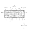
図1は、本発明の実施形態1に係るアクチュエータ1の外観斜視図である。図2は、図1のアクチュエータ1の分解斜視図である。図3は、図1のアクチュエータ1の断面図である。図4は、ケース9を取り外したアクチュエータ1を第1方向Zの他方側Z2から見た分解斜視図である。図5は、ケース9を取り外したアクチュエータ1を第1方向Zの一方側Z1から見た分解斜視図である。図6は、コイル6、コイルホルダ7および回路基板11の分解斜視図である。図7は、コイルホルダ7、接続体4および磁気駆動回路10の平面図である。
[Embodiment 1]
FIG. 1 is an external perspective view of an
(全体構成)
図1および図2に示すように、本発明の実施形態1のアクチュエータは、多角形のケース9を含む支持体2と、ケース9の内部に収容された可動体3とを有する。図3に示すように、可動体3は、可動体3と支持体2との間に配置された接続体4を介して、支持体2に支持される。接続体4は、弾性体または粘弾性体からなり、可動体3は、支持体2に対して、第2方向Xおよび第3方向Yに相対的に移動可能に支持される。本形態では、接続
体4は粘弾性体からなる。
(overall structure)
As shown in FIGS. 1 and 2, the actuator of
支持体2は、第2方向Xにおいて対向する一対の第1側辺部21と、第3方向Yにおいて対向する一対の第2側辺部22とを有する。すなわち、図1に示すように、アクチュエータ1は、第3方向Yに長手方向を向けた直方体形状である。支持体2は、コイル6、コイルホルダ7、ケース9および回路基板11を有する。可動体3は、第3方向Yに長手方向を向けた形状である。可動体3は、磁石5(図4、図5参照)およびヨーク8を有する。
The support body 2 has a pair of
磁石5とコイル6は、可動体3を第4方向Fに駆動する磁気駆動回路10(図7を参照)を構成する。後述するように、本形態では、接続体4は、可動体3が支持体2に対して第2方向Xに振動する第1振動系を構成し、かつ、可動体3が支持体2に対して第3方向Yに振動する第2振動系を構成し、第1振動系の共振周波数と、第2振動系の共振周波数とが異なることから、磁気駆動回路10が可動体3を第4方向Fに駆動した際、アクチュエータ1は、第2方向Xおよび第3方向Yの振動を出力する。本形態では、磁気駆動回路10が第3方向Yに2組並んでいる。接続体4は、第1接続体41および第2接続体42を有する。
The
アクチュエータ1は、可動体3が第2方向Xまたは第3方向Yに振動することにより、アクチュエータ1や、アクチュエータ1を取り付けた機器等を利用する者に触覚を与える触覚デバイスとして使用することができる。例えば、アクチュエータ1は、ゲーム機の操作部材、操作パネル、自動車のハンドルや座席等に組み込んで使用することができる。アクチュエータ1を触覚デバイスとして使用する際、可動体3が第2方向Xに振動する際の共振周波数fA(図8参照)と、可動体3が第3方向Yに振動する際の共振周波数fB(図8参照)とが異なるため、コイル6に印加する交流波形の周波数を調整して、可動体3を2種類の方向および周波数で振動させることができる。したがって、利用者に2種類の異なる振動を体感させることができる。また、コイル6に印加する交流波形を調整して、可動体3が一方側に移動する加速度と、可動体3が他方側に移動する加速度とを相違させれば、利用者は、方向性を有する振動を体感することができる。
The
(可動体3)
図4および図5に示すように、可動体3において、磁石5は、第1磁石51および第2磁石52を有する。第1磁石51は、コイル6に第1方向Zの一方側Z1で対向する。第2磁石52は、コイル6に第1方向Zの他方側Z2で対向する。第1磁石51および第2磁石52において、少なくともコイル6と対向する面は、第2方向Xおよび第3方向Yと交差する第4方向Fの一方側と他方側とが異なる極に着磁されている。本形態において、第1磁石51の少なくともコイル6と対向する面は、第2方向Xの一方側X1かつ第3方向Yの他方側Y2がN極に着磁され、第2方向Xの他方側X2かつ第3方向Yの一方側Y1がS極が着磁されている。これに対して、第2磁石52の少なくともコイル6と対向する面は、第2方向Xの他方側X2かつ第3方向Yの一方側Y1がN極に着磁され、第2方向Xの一方側X1かつ第3方向Yの他方側Y2がS極に着磁されている。従って、第1磁石51と第2磁石52とにおいて、コイル6を介して互いに対向する面は異なる極になっている。本形態では、磁気駆動回路10を2組有するため、第1磁石51および第2磁石52は、第4方向Fに傾いた状態で第3方向Yに2個並んでいる。
(Movable body 3)
As shown in FIGS. 4 and 5, in the movable body 3, the
ヨーク8は磁性材料からなり、本形態ではプレス加工により形成される。ヨーク8は、磁石5を保持する。図4、および図5に示すように、ヨーク8は、第1ヨーク81と、第1ヨーク81の第1方向Zの他方側Z2に位置する第2ヨーク82とによって構成される。第1ヨーク81は、第1板部811と、第1板部811の第3方向Yの両端の縁から第1方向Zの他方側Z2に折れ曲がった連結部812とを有する。第2ヨーク82は、平板
状の第2板部821を有する。
The
図4に示すように、第1磁石51は、第1ヨーク81の第1板部811の第1方向Zの他方側Z2の面に保持される。この際、第1磁石51は、第1板部811に設けられた位置決め部83により、第1板部811に位置決めされる。本形態では、位置決め部83は、半抜き加工により形成された複数のダボ831からなる。第1磁石51は、ダボ831で区画された部分に嵌め込まれることで、第1磁石51は、第1板部811に位置決めされる。
As shown in FIG. 4, the first magnet 51 is held on the surface of the
図5に示すように、第2磁石52は、第2ヨーク82の第2板部821の第1方向Zの一方側Z1の面に保持される。この際、第2磁石52は、第2板部821に設けられた位置決め部83により、第2板部821に位置決めされる。本形態では、位置決め部83は、半抜き加工により形成された複数のダボ831からなる。第2磁石52は、ダボ831で区画された部分に嵌め込まれることで、第2磁石52は、第2板部821に位置決めされる。
As shown in FIG. 5, the second magnet 52 is held on the surface of the
連結部812は、第3方向Yの一方側Y1に配置された第1連結部8121と、第3方向Yの他方側Y2に配置された第2連結部8122とを有する。第1連結部8121および第2連結部8122の第2方向Xの両端には、切り欠き部814が設けられる。第1連結部8121において、第1連結部8121の第2方向Xの一方側X1の端面に設けられた切り欠き部814は、第1方向Zの一方側Z1に寄っており、第1連結部8121の第2方向Xの他方側X2の端部に設けられた切り欠き部814は、第1方向Zの他方側Z2に寄っている。第2連結部8122において、第2連結部8122の第2方向Xの一方側X1の端面に設けられた切り欠き部814は、第1方向Zの他方側Z2に寄っており、第2連結部8122の第2方向Xの他方側X2の端部に設けられた切り欠き部814は、第1方向Zの一方側Z1に寄っている。
The connecting portion 812 includes a first connecting
第1連結部8121、および第2連結部8122の第1方向Zの他方側Z2の端部の中央部分には、凸部813が設けられる。第2板部821の第3方向Yの両端部の中央部分には凹部822が各々、設けられる。第1ヨーク81と第2ヨーク82は、凸部813と凹部822とが嵌合することで、連結される。そして、凸部813および凹部822を溶接等で固定することにより、第1ヨーク81および第2ヨーク82は連結されている。
A
(支持体2)
図1および図2に示すように、支持体2において、ケース9は、第1ケース部材91と、第2ケース部材92とを有する。第1ケース部材91と第2ケース部材92との間には、可動体3、コイル6およびコイルホルダ7が収容される。ケース9の第2方向Xの一方側X1の側面には、開口部93が形成され、開口部93から回路基板11が露出する。第1ケース部材91は、第3方向Yを向く底板部911と、底板部911の端縁から第3方向Yの他方側Y2に突出する側板部912とを有する。底板部911には、2つの貫通穴913が設けられる。第2方向Xの一方側X1の側板部912の中央部分には、切り欠き部914が設けられる。同様に、第2ケース部材92は、第3方向Yを向く底板部921と、底板部921の端縁から第3方向Yの一方側Y1に突出する側板部922とを有する。底板部921には、2つの貫通穴923が設けられる。第2方向Xの一方側X1の側板部922の中央部には、切り欠き部924が設けられる。本形態では、第1ケース部材91の側板部912、および第2ケース部材92の側板部922のうち、第2方向Xにおいて対向する部分によって、支持体2の一対の第1側辺部21が構成される。また、第1ケース部材91の底板部911、および第2ケース部材92の底板部921によって、支持体2の一対の第2側辺部22が構成される。
(Support 2)
As shown in FIGS. 1 and 2, in the support body 2, the case 9 includes a
貫通穴913は、第2方向Xにおいて、第1ヨーク81の切り欠き部814に対応する位置に設けられ、貫通穴923は、第2方向Xにおいて、第2ヨーク82の切り欠き部814に対応する位置に設けられる。具体的には、アクチュエータ1を組み立てる際に、可動体3およびコイルホルダ7をケース9に対して位置決めするために、位置決め用ピンが貫通穴913または貫通穴923から第3方向Yに挿入される。この時、貫通穴913、923から挿入された位置決め用ピンの側面が、第1ヨーク81の切り欠き部814および第2ヨーク82の切り欠き部814と嵌合する位置となるように、貫通穴913、923が設けられる。
The through
第1ケース部材91および第2ケース部材92は、第2方向Xで組付けられた状態で、溶接等により固定される。第1ケース部材91および第2ケース部材92が固定されると、切り欠き部914および切り欠き部924は、開口部93を構成する。
The
コイルホルダ7は、樹脂材料からなる。図4、図5、図6に示すように、コイルホルダ7は、コイル6と回路基板11とを保持する。コイルホルダ7は、第1方向Zから見た形状が長方形の本体部71と、本体部71の端縁から第1方向Zに突出する側面部72とを有する。本体部71には、第1方向Zの一方側Z1に凹んだ凹部73を有する。凹部73には、コイル6が配置される。凹部73は、第4方向Fに直交する第5方向Gが長手方向となる長円形であり、第4方向Fに直交する第5方向Gが長くなっている。凹部73は、中央部分が第1方向Zに貫通するとともに、第4方向Fの両端部分に底部731を有する。底部731は、コイル6と第1方向Zで当接することで、コイル6は凹部73に対して第1方向Zにおいて位置決めされる。
側面部72は、第2方向Xの一方側X1に位置する側壁721と、第2方向Xの他方側X2に位置する側壁722と、第3方向Yの一方側Y1に位置する側壁723と、第3方向Yの他方側Y2に位置する側壁724とを有する。側壁722には、第2方向Xの一方側X1に凹んだ位置決め段部740が設けられる。位置決め段部740には、回路基板11が第2方向Xの一方側X1から嵌め込まれる。
The side wall 72 includes a side wall 721 located on one side X1 in the second direction X, a
側壁723の第2方向Xの両端部には、第3方向Yの一方側Y1に突出するとともに、第1方向Zに延びる一対の第1柱状部75が設けられる。図3に示すように、第1柱状部75の第1方向Zの長さは、第1ケース部材91の内壁部に第1柱状部75が嵌合する寸法長さである。同様に、側壁724の第2方向Xの両端部には、第3方向Yの他方側Y2に突出するとともに、第1方向Zに延びる一対の第2柱状部76が設けられる。図3に示すように、第2柱状部76の第1方向Zの長さは、第2ケース部材92の内壁部に第2柱状部76が嵌合する寸法長さである
At both ends of the
コイルホルダ7において、側壁723は、ヨーク8の第1連結部8121と第3方向Yの他方側Y2で対向し、側壁724は、ヨーク8の第2連結部8122と第3方向Yの一方側Y1で対向する。したがって、側壁723および側壁724は、可動体3が第3方向Yに移動する際の可動範囲を規定する度当たり部として機能する。
In the
コイルホルダ7において、第1柱状部75は、ヨーク8の第1連結部8121と第2方向Xで対向し、第2柱状部76は、ヨーク8の第2連結部8122と第2方向Xで対向する。したがって、第1柱状部75および第2柱状部76は、可動体3が第2方向Xに移動する際の可動範囲を規定する度当たり部として機能する。
In the
コイル6は、接着剤によって、コイルホルダ7の凹部73に固定される。コイル6は、第4方向Fに直交する第5方向Gが長手方向である長円形であり、第4方向Fに直交する第5方向Gが長くなっている。すなわち、第2方向Xおよび第3方向Yに延びる支持体2
および可動体3の形状に対して、コイル6の長手方向が第4方向Fに直交する第5方向Gとなっているので、長手方向が第2方向Xまたは第3方向Yに延びるコイルと比べて、本形態のコイル6の長手方向は大きい。コイル6は、直線部分61と曲線部分62とを有する。直線部分61は、第4方向Fに直交する第5方向Gに延びる。コイル6は、第2方向Xの一方側X1から引き出された引き出し部分63を有する。引き出し部分63は、回路基板11に電気的に接続する。
The
With respect to the shape of the movable body 3, the longitudinal direction of the
アクチュエータ1は、回路基板11を介して外部(上位の機器)からコイル6に給電する。回路基板11は、コイルホルダ7に保持されて、ケース9の開口部93から露出する。
The
(接続体)
図2に示すように、可動体3は、可動体3および支持体2に接続された第1接続体41および第2接続体42によって、支持体2に対して第2方向Xおよび第3方向Yに相対移動可能に支持される。第1接続体41は、第1ケース部材91とヨーク8の第1連結部8121との間に配置され、接着剤等により固定される。第2接続体42は、第2ケース部材92とヨーク8の第2連結部8122との間に配置され、接着剤等により固定される。第1接続体41および第2接続体42は、第3方向Yに圧縮された状態にある。
(connection body)
As shown in FIG. 2, the movable body 3 is moved in a second direction It is supported so that it can move relative to Y. The first connecting
可動体3が第2方向Xに振動する際、アクチュエータ1は、第1接続体41および第2接続体42がせん断方向に変形する第1振動系を構成する。可動体3が第3方向Yに振動する際、アクチュエータ1は、第1接続体41および第2接続体42が伸縮方向に変形する第2振動系を構成する。
When the movable body 3 vibrates in the second direction X, the
第1接続体41および第2接続体42は、伸縮方向に変形する際のばね定数とせん断方向に変形する際のばね定数が異なる。本形態では、第1接続体41および第2接続体42は粘弾性体である。例えば、第1接続体41および第2接続体42は、シリコーンゲル等からなるゲル状部材である。シリコーンゲルは、伸縮方向に変形する際のばね定数が、せん断方向に変形する際のばね定数の3倍程度になる粘弾性体である。粘弾性体は、厚さ方向と交差する方向(せん断方向)に変形する場合、引っ張られて伸びる方向の変形であるため、非線形の成分よりも線形の成分が大きい変形特性を備える。また、厚さ方向に押圧されて圧縮変形する際は、線形の成分よりも非線形の成分が大きい伸縮特性を備える一方、厚さ方向に引っ張られて伸びる場合は、非線形の成分よりも線形の成分が大きい伸縮特性を備える。
The first connecting
第1接続体41および第2接続体42として、天然ゴム、ジエン系ゴム(例えば、スチレン・ブタジエンゴム、イソプレンゴム、ブタジエンゴム、クロロプレンゴム、アクリロニトリル・ブタジエンゴム等)、非ジエン系ゴム(例えば、ブチルゴム、エチレン・プロピレンゴム、エチレン・プロピレン・ジエンゴム、ウレタンゴム、シリコーンゴム、フッ素ゴム等)、熱可塑性エラストマー等の各種ゴム材料及びそれらの変性材料を用いてもよい。
The
(磁気駆動回路)
図7に示すように、アクチュエータ1は、磁石5と長円形のコイル6の対からなる磁気駆動回路10を2組有する。各磁気駆動回路10は、第2方向Xおよび第3方向Yを含む面内方向であって、第2方向Xおよび第3方向Yとは異なる第4方向Fに働く駆動力を発生させる。例えば、第4方向Fは、第2方向Xおよび第3方向Yに対して45°傾いた方向である。各磁気駆動回路10において、磁石5は、コイル6と対向する面がN極とS極に着磁され、その着磁分極線50は、第4方向Fに対して直交する第5方向Gに延びる。本形態では、第4方向Fの方向に磁石5が着磁されている。第1磁石51および第2磁石
52は、第1方向Zから見たときに、第1方向Zで対向するコイル6の直線部分61の一部と重なるように配置される。
(Magnetic drive circuit)
As shown in FIG. 7, the
(アクチュエータの位置決め調整)
アクチュエータ1を組み立てる際に、可動体3およびコイルホルダ7をケース9に対して位置決め調整を行う。位置決めするために、位置決め用ピン(不図示)が貫通穴913または貫通穴923から第3方向Yに挿入される。この時、貫通穴913、923から挿入された位置決め用ピンの側面が、第1ヨーク81の切り欠き部814および第2ヨーク82の切り欠き部814と嵌合するとともに、位置決め用ピンの先端が、コイルホルダ7と第2方向Xにおいて当接する。この結果、位置決め用ピンの位置を調整することで、可動体3およびコイルホルダ7がケース9に対して位置決め調整することが可能となる。
(Actuator positioning adjustment)
When assembling the
(アクチュエータの駆動方法)
図8は、アクチュエータ1の振動特性を模式的に示す説明図である。図8の横軸は磁気駆動回路10の駆動周波数fであり、コイル6へ流す駆動電流の周波数である。また、図8の縦軸は、可動体3が振動する際の加速度である。上記のように、アクチュエータ1は、可動体3が第2方向Xに振動する第1振動系を構成する場合と、可動体3が第3方向Yに振動する第2振動系を構成する場合とで、接続体4が全体として異なるばね定数で変形するように構成されている。そのため、アクチュエータ1は、第1振動系の共振周波数fAと、第2振動系の共振周波数fBとが異なり、図8に示すように、2つの共振周波数fA、fBで可動体3の加速度最大周波数が大きくなっている。
(Actuator driving method)
FIG. 8 is an explanatory diagram schematically showing the vibration characteristics of the
磁気駆動回路10が発生させる駆動力は、第2方向Xの成分と第3方向Yの成分を含む第4方向Fの駆動力である。したがって、磁気駆動回路10の駆動周波数を変化させると、共振周波数fAと一致あるいは共振周波数fAに近い値の駆動周波数にしたとき、可動体3が第2方向Xに大きく振動する。この結果、アクチュエータ1は、共振周波数fAの第2方向Xの振動を出力することができる。また、磁気駆動回路10の駆動周波数を共振周波数fBと一致あるいは共振周波数fBに近い値にしたとき、可動体3が第3方向Yに大きく振動する。この結果、アクチュエータ1は、共振周波数fBの第3方向Yの振動を出力することができる。よって、アクチュエータ1は、共通の磁気駆動回路10の駆動周波数を調節するだけで、異なる振動方向で、且つ、異なる周波数の振動を出力することができる。
The driving force generated by the
(本形態の主な効果)
本形態では、支持体2は、第1方向Zと直交する第2方向Xにおいて対向する一対の第1側辺部21と、第1方向Zと直交するとともに第2方向Xと交差する第3方向Yにおいて対向する一対の第2側辺部22とを有する。磁気駆動回路10は、可動体3を支持体2に対し、第2方向Xおよび第3方向Yとは異なる第4方向Fに駆動する。コイル6は、第4方向Fに直交する第5方向Gに延びる長円形である。磁石5は、第4方向Fに着磁されている。したがって、磁気駆動回路10が第4方向Fに駆動するため、可動体3の移動距離(移動量)を大きく確保することができる。また、第2方向Xにおいて対向する一対の第1側辺部21と、第3方向Yにおいて対向する一対の第2側辺部22とを有する支持体2に対して、コイル6は第4方向Fに直交する第5方向Gに延びる長円形である。このため、コイル6が第2方向Xおよび第3方向Yの何れかに延びる長円形に比べて、コイル6の長手方向の長さを大きくすることができる。この結果、アクチュエータ1において、磁気駆動回路10が発生させる第4方向Fへの駆動力を大きくすることができる。
(Main effects of this form)
In this embodiment, the support body 2 has a pair of
本形態では、コイル6は、第4方向Fに直交する第5方向Gに延びる直線部分61を有し、磁石5は、第1方向Zから見たときに、コイル6の直線部分61の少なくとも一部と重なる。このようにすれば、磁気駆動回路10が発生させる第4方向Fへの駆動力を効率
的に大きくすることができる。
In this embodiment, the
本形態では、接続体4は、可動体3が支持体2に対し、第2方向Xに振動する第1振動系を構成し、かつ、可動体3が支持体2に対し、第3方向Yに振動する第2振動系を構成し、第1振動系の共振周波数fAと、第2振動系の共振周波数fBとが異なる。このようにすれば、可動体3が第2方向Xに振動する際と、第3方向Yに振動する際とでは、可動体3を振動させる振動系の共振周波数が異なる。したがって、接続体4によって、共振周波数が異なる複数の振動系を構成できる。また、共振周波数だけでなく、振動の方向も異なる。したがって、簡素な構成で、2種類の共振周波数および2種類の方向の振動を出力することができる。
In this embodiment, the connecting
本形態では、可動体3は、ヨーク8を有し、ヨーク8は、磁石5を位置決めする位置決め部83を有する。このようにすれば、磁石5をヨーク8に位置決めすることが容易となる。
In this embodiment, the movable body 3 has a
本発明において、ヨーク8は、第1方向Zで分割される、第1ヨーク81および第2ヨーク82からなり、第1ヨーク81および第2ヨーク82は同一形状である。このようにすれば、ヨーク8を構成する第1ヨーク81および第2ヨーク82を共通とすることができるので、部品点数を削減することができる。
In the present invention, the
本形態では、コイルホルダ7は、コイル6を収容する凹部822を有する。このようにすれば、コイルホルダ7でコイル6を保持することが容易となる。
In this embodiment, the
本形態では、支持体2は、可動体3を収容するケース9を有し、ケース9は、第2方向Xおよび第3方向Yのうち、接続体4が配置された方向に貫通穴913、923を有し、ヨーク8は、第2方向Xおよび第3方向Yのうち、接続体4が配置された方向に切り欠き部814を有する。このようにすれば、アクチュエータ1を組み立てる際に、可動体3およびコイルホルダ7をケース9に対して位置決めするための位置決め用ピンを用いることができるので、可動体3およびコイルホルダ7がケース9に対して位置決め調整することが容易となる。
In this embodiment, the support body 2 has a case 9 that accommodates the movable body 3, and the case 9 has a through
[実施形態2]
図9は、本発明の実施形態2のヨーク8の斜視図である。図10は、実施形態2の第1ヨーク86の斜視図である。実施形態2では、上記形態のヨーク8の第1ヨーク81および第2ヨーク82の形状とは異なる形状であり、他の構成は同一である。
[Embodiment 2]
FIG. 9 is a perspective view of the
図9に示すように、ヨーク8は、第1方向Zで重なる第1ヨーク86および第2ヨーク87からなる。第1ヨーク86および第2ヨーク87は同一形状である。具体的には、図10に示すように、第1ヨーク86は、第2方向Xから見たときの形状が、L字の形状である。第1ヨーク86は、板部881と、板部881の第3方向Yの他方側Y2の端縁から第1方向Zの他方側Z2に突出した連結部882とを有する。連結部882の第1方向Zの一方側Z1の端部の中央部分には、凸部883が設けられる。板部881の第3方向Yの一方側Y1の端部の中央部分には、凹部884が設けられる。連結部882の第2方向Xの両端には、切り欠き部885が設けられる。ここで、第2ヨーク87は、第1ヨーク86と同一形状であるので、同一部分には同一の符号を付す。したがって、図9に示すように、第1ヨーク86と第2ヨーク87は、凸部883と凹部884とが嵌合することで、組み立てられる。そして、凸部883および凹部884を溶接等で固定することで、第1ヨーク86および第2ヨーク87は、連結している。このように、第1ヨーク86と第2ヨーク87は、同一形状であるので、部品点数を削減することができる。
As shown in FIG. 9, the
[実施形態3]
図11は、本発明の実施形態3のアクチュエータ1の断面図である。実施形態3は、上記形態2とは、接続体4の配置される位置が異なり、他の構成は同一である。図11に示すように、実施形態3では、接続体4は、第1接続体41と、第2接続体42とを有する。第1接続体41は、第2ヨーク87の連結部882の内側(第3方向Yの他方側Y2)において、第2ヨーク87の連結部882とコイルホルダ7との間に配置される。第2接続体42は、第1ヨーク86の連結部882の内側(第3方向Yの一方側Y1)において、第1ヨーク86の連結部882とコイルホルダ7との間に配置される。より具体的には、第1接続体41は、第2ヨーク87の連結部882と側壁723との間に配置される。第2接続体42は、第1ヨーク86の連結部882と側壁724との間に配置される。このようにすることで、ヨーク8が第3方向Yに大きくなり、ヨーク8の質量が増加する。この結果、可動体3の質量を増大することができるので、可動体3の移動距離(移動量)が同程度または小さくても、推力を向上または維持できる。また、ケース9に外力が加わっても、外力が直接接続体4に伝わらないため、接続体4の変形を抑制することができる。また、本形態の第1ヨーク86および第2ヨーク87の形状であれば、接続体4をヨーク8の内側に配置することが容易となる。
[Embodiment 3]
FIG. 11 is a sectional view of the
[他の実施形態]
上記形態は、可動体3と支持体2とが第3方向Yで対向する位置に接続体4を配置するものであったが、接続体4の位置は、可動体3と支持体2とが第2方向Xで対向する位置であってもよい。また、接続体4を配置する位置を、可動体3と支持体2とが第2方向Xで対向する位置、および、可動体3と支持体2とが第3方向Yで対向する位置の両方としてもよい。
[Other embodiments]
In the above embodiment, the connecting
上記形態は、コイル6に対する第1方向Zの両側に磁石5(第1磁石51および第2磁石52)を配置しているが、コイル6に対する第1方向Zの一方側Z1または他方側Z2のみに磁石5を配置してもよい。
In the above embodiment, the magnets 5 (first magnet 51 and second magnet 52) are arranged on both sides of the first direction Z with respect to the
上記形態では、コイル6およびコイルホルダ7を支持体2に設け、磁石5(第1磁石51および第2磁石52)およびヨーク8(第1ヨーク81および第2ヨーク82)を可動体3に設けたが、コイル6およびコイルホルダ7を可動体3に設け、磁石5(第1磁石51および第2磁石52)およびヨーク8(第1ヨーク81および第2ヨーク82)を支持体2に設けたアクチュエータに本発明を適用してもよい。
In the above embodiment, the
上記形態では、磁石5とコイル6の組を2組備えているが、1組もしくは3組以上であってもよい。また、磁石5とコイル6の組が3組以上である場合、第2方向Xおよび第3方向Yにそれぞれ複数並んでいてもよい。
In the above embodiment, two sets of
上記形態では、第1ケース部材91および第2ケース部材92は、貫通穴913、923を有しているが、切り欠き部であってもよい。また、連結部812は、切り欠き部814を有しているが、穴であってもよい。何れの場合でも、アクチュエータ1を組み立てる際に、位置決め用ピンを用いて、可動体3およびコイルホルダ7をケース9に対して位置決めすることができる。
In the above embodiment, the
上記形態では、第4方向Fは、第2方向Xおよび第3方向Yに対して45°傾いた方向であったが、これに限定されない。例えば、第4方向Fは、第2方向Xおよび第3方向Yに対して30°傾いた方向であってもよい。このように構成しても、コイル6が第2方向Xおよび第3方向Yの何れかに延びる長円形に比べて、コイル6の長手方向の長さを大きくすることができる。
In the above embodiment, the fourth direction F is a direction inclined by 45 degrees with respect to the second direction X and the third direction Y, but the present invention is not limited thereto. For example, the fourth direction F may be a direction inclined by 30 degrees with respect to the second direction X and the third direction Y. Even with this configuration, the length of the
1…アクチュエータ、2…支持体、3…可動体、4…接続体、5…磁石、6…コイル、7…コイルホルダ、8…ヨーク、9…ケース、10…磁気駆動回路、11…回路基板、21…第1側辺部、22…第2側辺部、41…第1接続体、42…第2接続体、50…着磁分極線、51…第1磁石、52…第2磁石、61…直線部分、62…曲線部分、63…引き出し部分、71…本体部、72…側面部、721、722、723、724…側壁、73…凹部、731…底部、75…第1柱状部、76…第2柱状部、740…位置決め段部、81…第1ヨーク、811…第1板部、812…連結部、8121…第1連結部、8122…第2連結部、813…凸部、814…切り欠き部、82…第2ヨーク、821…第2板部、822…凹部、83…位置決め部、831…ダボ、86…第1ヨーク、87…第2ヨーク、881…板部、882…連結部、883…凸部、884…凹部、885…切り欠き部、91…第1ケース部材、911…底板部、912…側板部、913…貫通穴、914…切り欠き部、92…第2ケース部材、921…底板部、922…底板部、923…貫通穴、924…切り欠き部、93…開口部
DESCRIPTION OF
Claims (9)
可動体と、
前記支持体および前記可動体に接続された接続体と、
前記支持体および前記可動体の一方側に配置された磁石と、前記支持体および前記可動体の他方側に配置されるとともに、第1方向で前記磁石と対向するコイルとを有する磁気駆動回路とを備え、
前記支持体は、前記第1方向と直交する第2方向において対向する一対の第1側辺部と、前記第1方向および前記第2方向に対して交差する第3方向において対向する一対の第2側辺部と、を有し、
前記コイルは、前記第1方向から見たときに、前記第2方向および前記第3方向に対して斜めに交差する第4方向と直交する第5方向に延在する長円形であり、前記磁石は前記第4方向に着磁され、前記磁気駆動回路は、前記可動体を前記支持体に対して前記第4方向に駆動し、
前記接続体は、弾性体または粘弾性体であり、前記第2方向および前記第3方向の少なくともいずれか一方において前記支持体と前記可動体との間に配置され、
前記可動体は、ヨークを有し、
前記ヨークは、前記磁石を位置決めする位置決め部を有し、
前記ヨークは、前記第1方向で対向する一対の板部と、前記一対の板部の前記第2方向および前記第3方向の何れか一方の辺において前記一対の板部の間で前記一対の板部を連結する一対の連結部と、を有し、
前記位置決め部は、前記一対の板部の板部のそれぞれから突出する複数の半抜き加工部であり、
前記磁石は、前記半抜き加工部の間に嵌め込まれていることを特徴とするアクチュエータ。 a support and
A movable body,
a connection body connected to the support body and the movable body;
A magnetic drive circuit including a magnet disposed on one side of the support and the movable body, and a coil disposed on the other side of the support and the movable body and facing the magnet in a first direction. Equipped with
The support body includes a pair of first side portions facing each other in a second direction perpendicular to the first direction, and a pair of first side portions facing each other in a third direction crossing the first direction and the second direction. having two side parts;
The coil has an oval shape extending in a fifth direction perpendicular to a fourth direction diagonally intersecting the second direction and the third direction when viewed from the first direction, and the coil is magnetized in the fourth direction, and the magnetic drive circuit drives the movable body in the fourth direction with respect to the support body,
The connecting body is an elastic body or a viscoelastic body, and is arranged between the support body and the movable body in at least one of the second direction and the third direction,
The movable body has a yoke,
The yoke has a positioning part that positions the magnet,
The yoke includes a pair of plate portions facing each other in the first direction, and a side of the pair of plate portions in either the second direction or the third direction of the pair of plate portions. A pair of connecting parts connecting the plate parts,
The positioning portion is a plurality of half-blanked portions protruding from each of the plate portions of the pair of plate portions,
The actuator is characterized in that the magnet is fitted between the half-blanked portion .
前記ヨークは、前記第1方向に重ねて配置された第1ヨークおよび第2ヨークからなり、
前記第1ヨークおよび前記第2ヨークは同一形状であることを特徴とするアクチュエータ。 In claim 1 ,
The yoke includes a first yoke and a second yoke that are arranged one on top of the other in the first direction,
An actuator characterized in that the first yoke and the second yoke have the same shape.
可動体と、
前記支持体および前記可動体に接続された接続体と、
前記支持体および前記可動体の一方側に配置された磁石と、前記支持体および前記可動体の他方側に配置されるとともに、第1方向で前記磁石と対向するコイルとを有する磁気駆動回路とを備え、
前記支持体は、前記第1方向と直交する第2方向において対向する一対の第1側辺部と、前記第1方向および前記第2方向に対して交差する第3方向において対向する一対の第2側辺部と、を有し、
前記コイルは、前記第1方向から見たときに、前記第2方向および前記第3方向に対して斜めに交差する第4方向と直交する第5方向に延在する長円形であり、前記磁石は前記第4方向に着磁され、前記磁気駆動回路は、前記可動体を前記支持体に対して前記第4方向に駆動し、
前記接続体は、弾性体または粘弾性体であり、前記第2方向および前記第3方向の少なくともいずれか一方において前記支持体と前記可動体との間に配置され、
前記可動体は、ヨークを有し、
前記ヨークは、前記第1方向で対向する一対の板部と、前記一対の板部の前記第2方向および前記第3方向の何れか一方の辺において前記一対の板部の間で前記一対の板部を連結する一対の連結部と、を有し、
前記支持体は、前記一対の連結部の間で前記コイルを保持するコイルホルダを有し、
前記接続体は、前記一対の連結部と前記コイルホルダとの各間に配置されることを特徴とするアクチュエータ。 a support and
A movable body,
a connection body connected to the support body and the movable body;
A magnetic drive circuit including a magnet disposed on one side of the support and the movable body, and a coil disposed on the other side of the support and the movable body and facing the magnet in a first direction. Equipped with
The support body includes a pair of first side portions facing each other in a second direction perpendicular to the first direction, and a pair of first side portions facing each other in a third direction crossing the first direction and the second direction. having two side parts;
The coil has an oval shape extending in a fifth direction perpendicular to a fourth direction diagonally intersecting the second direction and the third direction when viewed from the first direction, and the coil is magnetized in the fourth direction, and the magnetic drive circuit drives the movable body in the fourth direction with respect to the support body,
The connecting body is an elastic body or a viscoelastic body, and is arranged between the support body and the movable body in at least one of the second direction and the third direction,
The movable body has a yoke,
The yoke includes a pair of plate portions facing each other in the first direction, and a side of the pair of plate portions in either the second direction or the third direction of the pair of plate portions. A pair of connecting parts connecting the plate parts,
The support body has a coil holder that holds the coil between the pair of connecting parts,
The actuator is characterized in that the connecting body is disposed between each of the pair of connecting parts and the coil holder.
前記コイルホルダは、前記コイルを収容する凹部を有することを特徴とするアクチュエータ。 In claim 3 ,
The actuator is characterized in that the coil holder has a recess that accommodates the coil.
可動体と、
前記支持体および前記可動体に接続された接続体と、
前記支持体および前記可動体の一方側に配置された磁石と、前記支持体および前記可動体の他方側に配置されるとともに、第1方向で前記磁石と対向するコイルとを有する磁気駆動回路とを備え、
前記支持体は、前記第1方向と直交する第2方向において対向する一対の第1側辺部と、前記第1方向および前記第2方向に対して交差する第3方向において対向する一対の第2側辺部と、を有し、
前記コイルは、前記第1方向から見たときに、前記第2方向および前記第3方向に対して斜めに交差する第4方向と直交する第5方向に延在する長円形であり、前記磁石は前記第4方向に着磁され、前記磁気駆動回路は、前記可動体を前記支持体に対して前記第4方向に駆動し、
前記接続体は、弾性体または粘弾性体であり、前記第2方向および前記第3方向の少なくともいずれか一方において前記支持体と前記可動体との間に配置され、
前記可動体は、ヨークを有し、
前記支持体は、前記可動体を収容するケースを有し、
前記ケースおよび前記ヨークは、前記第2方向および前記第3方向のうち、前記接続体が配置された方向に穴または切り欠き部を有することを特徴とするアクチュエータ。 a support and
A movable body,
a connection body connected to the support body and the movable body;
A magnetic drive circuit including a magnet disposed on one side of the support and the movable body, and a coil disposed on the other side of the support and the movable body and facing the magnet in a first direction. Equipped with
The support body includes a pair of first side portions facing each other in a second direction perpendicular to the first direction, and a pair of first side portions facing each other in a third direction crossing the first direction and the second direction. having two side parts;
The coil has an oval shape extending in a fifth direction perpendicular to a fourth direction diagonally intersecting the second direction and the third direction when viewed from the first direction, and the coil is magnetized in the fourth direction, and the magnetic drive circuit drives the movable body in the fourth direction with respect to the support body,
The connecting body is an elastic body or a viscoelastic body, and is arranged between the support body and the movable body in at least one of the second direction and the third direction,
The movable body has a yoke,
The support body has a case that houses the movable body,
The actuator is characterized in that the case and the yoke have a hole or a notch in a direction in which the connecting body is arranged, out of the second direction and the third direction.
前記ヨークは、前記第1方向で対向する一対の板部と、前記一対の板部の前記第2方向
および前記第3方向の何れか一方の辺において前記一対の板部の間で前記一対の板部を連結する一対の連結部と、を有し、
前記支持体は、前記一対の連結部の間で前記コイルを保持するコイルホルダを有し、
前記ヨークに設けられた前記穴または前記切り欠き部は、前記ケースに設けられた前記穴または前記切り欠き部から挿入された位置決め用ピンが嵌合する位置に配置され、前記コイルホルダは、前記位置決め用ピンの先端が当接する位置に配置されることを特徴とするアクチュエータ。 In claim 5 ,
The yoke includes a pair of plate portions facing each other in the first direction, and a side of the pair of plate portions in either the second direction or the third direction of the pair of plate portions. A pair of connecting parts connecting the plate parts,
The support body has a coil holder that holds the coil between the pair of connecting parts,
The hole or the notch provided in the yoke is arranged at a position where a positioning pin inserted through the hole or the notch provided in the case fits, and the coil holder is arranged in the hole or the notch provided in the case. An actuator characterized in that the actuator is arranged at a position where the tip of a positioning pin abuts.
前記コイルは、前記第1方向から見たときに前記第5方向に延在する直線部分を有し、
前記磁石は、前記第1方向から見たときに、前記コイルの前記直線部分の少なくとも一部と重なることを特徴とするアクチュエータ。 In any one of claims 1, 3, and 5 ,
The coil has a straight portion extending in the fifth direction when viewed from the first direction,
The actuator is characterized in that the magnet overlaps at least a portion of the linear portion of the coil when viewed from the first direction.
前記接続体は、前記可動体が前記支持体に対して前記第2方向に振動する第1振動系を構成し、かつ、前記可動体が前記支持体に対して前記第3方向に振動する第2振動系を構成し、
前記第1振動系の共振周波数と、前記第2振動系の共振周波数とが異なることを特徴とするアクチュエータ。 In any one of claims 1, 3, and 5 ,
The connecting body constitutes a first vibration system in which the movable body vibrates in the second direction with respect to the support body, and a first vibration system in which the movable body vibrates in the third direction with respect to the support body. Constructs a two-vibration system,
An actuator characterized in that the resonance frequency of the first vibration system and the resonance frequency of the second vibration system are different.
前記可動体が振動することにより触覚を与える触覚デバイスとして使用されることを特徴とするアクチュエータ。
In any one of claims 1 to 8 ,
An actuator characterized in that the movable body is used as a tactile device that provides a tactile sensation by vibrating.
Priority Applications (4)
| Application Number | Priority Date | Filing Date | Title |
|---|---|---|---|
| JP2019179721A JP7402006B2 (en) | 2019-09-30 | 2019-09-30 | actuator |
| CN202010476413.2A CN112018992B (en) | 2019-05-31 | 2020-05-29 | Actuator and haptic device |
| CN202010474946.7A CN112018991B (en) | 2019-05-31 | 2020-05-29 | Actuator and haptic device |
| CN202010474913.2A CN112018990B (en) | 2019-05-31 | 2020-05-29 | Actuator and haptic device |
Applications Claiming Priority (1)
| Application Number | Priority Date | Filing Date | Title |
|---|---|---|---|
| JP2019179721A JP7402006B2 (en) | 2019-09-30 | 2019-09-30 | actuator |
Publications (2)
| Publication Number | Publication Date |
|---|---|
| JP2021057993A JP2021057993A (en) | 2021-04-08 |
| JP7402006B2 true JP7402006B2 (en) | 2023-12-20 |
Family
ID=75273076
Family Applications (1)
| Application Number | Title | Priority Date | Filing Date |
|---|---|---|---|
| JP2019179721A Active JP7402006B2 (en) | 2019-05-31 | 2019-09-30 | actuator |
Country Status (1)
| Country | Link |
|---|---|
| JP (1) | JP7402006B2 (en) |
Citations (7)
| Publication number | Priority date | Publication date | Assignee | Title |
|---|---|---|---|---|
| JP2005227329A (en) | 2004-02-10 | 2005-08-25 | Canon Inc | Blur correcting device and optical equipment |
| JP5293441B2 (en) | 2009-06-17 | 2013-09-18 | 富士通株式会社 | Phase correction apparatus and phase correction method |
| CN105048757A (en) | 2015-08-18 | 2015-11-11 | 歌尔声学股份有限公司 | Vibration motor electronic equipment |
| WO2018030265A1 (en) | 2016-08-09 | 2018-02-15 | 日本電産サンキョー株式会社 | Linear actuator |
| CN108199555A (en) | 2018-01-03 | 2018-06-22 | 瑞声科技(南京)有限公司 | Vibrating motor |
| JP2018161047A (en) | 2014-05-21 | 2018-10-11 | ミネベアミツミ株式会社 | Vibration generator |
| JP2020511911A (en) | 2018-03-02 | 2020-04-16 | 金竜機電股▲ふん▼有限公司 | Moving coil linear vibration motor |
Family Cites Families (4)
| Publication number | Priority date | Publication date | Assignee | Title |
|---|---|---|---|---|
| JPH05293441A (en) * | 1992-04-17 | 1993-11-09 | Olympus Optical Co Ltd | Ultrasonic vibrator |
| JP6253157B2 (en) * | 2014-11-14 | 2017-12-27 | アルプス電気株式会社 | Vibration generator |
| JP6056883B2 (en) * | 2015-01-23 | 2017-01-11 | ミツミ電機株式会社 | Lens driving device, camera module, and mobile terminal with camera |
| JP2019013095A (en) * | 2017-06-30 | 2019-01-24 | 日本電産サンキョー株式会社 | Actuator |
-
2019
- 2019-09-30 JP JP2019179721A patent/JP7402006B2/en active Active
Patent Citations (7)
| Publication number | Priority date | Publication date | Assignee | Title |
|---|---|---|---|---|
| JP2005227329A (en) | 2004-02-10 | 2005-08-25 | Canon Inc | Blur correcting device and optical equipment |
| JP5293441B2 (en) | 2009-06-17 | 2013-09-18 | 富士通株式会社 | Phase correction apparatus and phase correction method |
| JP2018161047A (en) | 2014-05-21 | 2018-10-11 | ミネベアミツミ株式会社 | Vibration generator |
| CN105048757A (en) | 2015-08-18 | 2015-11-11 | 歌尔声学股份有限公司 | Vibration motor electronic equipment |
| WO2018030265A1 (en) | 2016-08-09 | 2018-02-15 | 日本電産サンキョー株式会社 | Linear actuator |
| CN108199555A (en) | 2018-01-03 | 2018-06-22 | 瑞声科技(南京)有限公司 | Vibrating motor |
| JP2020511911A (en) | 2018-03-02 | 2020-04-16 | 金竜機電股▲ふん▼有限公司 | Moving coil linear vibration motor |
Also Published As
| Publication number | Publication date |
|---|---|
| JP2021057993A (en) | 2021-04-08 |
Similar Documents
| Publication | Publication Date | Title |
|---|---|---|
| JP7007911B2 (en) | Linear actuator | |
| CN110800200B (en) | Actuator | |
| JPWO2018180947A1 (en) | Actuator | |
| WO2019003874A1 (en) | Actuator | |
| JP6944288B2 (en) | Actuator | |
| JP6858088B2 (en) | Actuator | |
| CN112018992B (en) | Actuator and haptic device | |
| JP7402006B2 (en) | actuator | |
| US11323015B2 (en) | Actuator | |
| US11070120B2 (en) | Actuator | |
| WO2018030269A1 (en) | Vibration generation device | |
| JP2022170145A (en) | actuator | |
| JP2023065769A (en) | actuator | |
| JP7252720B2 (en) | actuator | |
| JP7410705B2 (en) | Actuators and haptic devices | |
| JP7325225B2 (en) | actuator | |
| JP2020162393A (en) | Actuator | |
| JP7267551B2 (en) | actuator | |
| US20220352802A1 (en) | Actuator | |
| JP2022020185A (en) | Actuator and haptic device | |
| JP2020137346A (en) | Actuator | |
| JP2021030188A (en) | Electronic instrument | |
| JP2019037015A (en) | Actuator | |
| JP2019034252A (en) | Actuator | |
| JP2019037014A (en) | Actuator |
Legal Events
| Date | Code | Title | Description |
|---|---|---|---|
| A621 | Written request for application examination |
Free format text: JAPANESE INTERMEDIATE CODE: A621 Effective date: 20220901 |
|
| A977 | Report on retrieval |
Free format text: JAPANESE INTERMEDIATE CODE: A971007 Effective date: 20230608 |
|
| A131 | Notification of reasons for refusal |
Free format text: JAPANESE INTERMEDIATE CODE: A131 Effective date: 20230620 |
|
| A521 | Request for written amendment filed |
Free format text: JAPANESE INTERMEDIATE CODE: A523 Effective date: 20230810 |
|
| A131 | Notification of reasons for refusal |
Free format text: JAPANESE INTERMEDIATE CODE: A131 Effective date: 20230905 |
|
| A521 | Request for written amendment filed |
Free format text: JAPANESE INTERMEDIATE CODE: A523 Effective date: 20231102 |
|
| TRDD | Decision of grant or rejection written | ||
| A01 | Written decision to grant a patent or to grant a registration (utility model) |
Free format text: JAPANESE INTERMEDIATE CODE: A01 Effective date: 20231114 |
|
| A61 | First payment of annual fees (during grant procedure) |
Free format text: JAPANESE INTERMEDIATE CODE: A61 Effective date: 20231208 |
|
| R150 | Certificate of patent or registration of utility model |
Ref document number: 7402006 Country of ref document: JP Free format text: JAPANESE INTERMEDIATE CODE: R150 |