JP7401552B2 - Laser equipment and laser equipment leak check method - Google Patents
Laser equipment and laser equipment leak check method Download PDFInfo
- Publication number
- JP7401552B2 JP7401552B2 JP2021550928A JP2021550928A JP7401552B2 JP 7401552 B2 JP7401552 B2 JP 7401552B2 JP 2021550928 A JP2021550928 A JP 2021550928A JP 2021550928 A JP2021550928 A JP 2021550928A JP 7401552 B2 JP7401552 B2 JP 7401552B2
- Authority
- JP
- Japan
- Prior art keywords
- gas
- laser
- pipe
- closed space
- neon
- Prior art date
- Legal status (The legal status is an assumption and is not a legal conclusion. Google has not performed a legal analysis and makes no representation as to the accuracy of the status listed.)
- Active
Links
Images


Classifications
-
- H—ELECTRICITY
- H01—ELECTRIC ELEMENTS
- H01S—DEVICES USING THE PROCESS OF LIGHT AMPLIFICATION BY STIMULATED EMISSION OF RADIATION [LASER] TO AMPLIFY OR GENERATE LIGHT; DEVICES USING STIMULATED EMISSION OF ELECTROMAGNETIC RADIATION IN WAVE RANGES OTHER THAN OPTICAL
- H01S3/00—Lasers, i.e. devices using stimulated emission of electromagnetic radiation in the infrared, visible or ultraviolet wave range
- H01S3/0014—Monitoring arrangements not otherwise provided for
-
- H—ELECTRICITY
- H01—ELECTRIC ELEMENTS
- H01S—DEVICES USING THE PROCESS OF LIGHT AMPLIFICATION BY STIMULATED EMISSION OF RADIATION [LASER] TO AMPLIFY OR GENERATE LIGHT; DEVICES USING STIMULATED EMISSION OF ELECTROMAGNETIC RADIATION IN WAVE RANGES OTHER THAN OPTICAL
- H01S3/00—Lasers, i.e. devices using stimulated emission of electromagnetic radiation in the infrared, visible or ultraviolet wave range
- H01S3/02—Constructional details
- H01S3/03—Constructional details of gas laser discharge tubes
- H01S3/036—Means for obtaining or maintaining the desired gas pressure within the tube, e.g. by gettering, replenishing; Means for circulating the gas, e.g. for equalising the pressure within the tube
-
- G—PHYSICS
- G01—MEASURING; TESTING
- G01M—TESTING STATIC OR DYNAMIC BALANCE OF MACHINES OR STRUCTURES; TESTING OF STRUCTURES OR APPARATUS, NOT OTHERWISE PROVIDED FOR
- G01M3/00—Investigating fluid-tightness of structures
- G01M3/02—Investigating fluid-tightness of structures by using fluid or vacuum
- G01M3/04—Investigating fluid-tightness of structures by using fluid or vacuum by detecting the presence of fluid at the leakage point
- G01M3/20—Investigating fluid-tightness of structures by using fluid or vacuum by detecting the presence of fluid at the leakage point using special tracer materials, e.g. dye, fluorescent material, radioactive material
- G01M3/22—Investigating fluid-tightness of structures by using fluid or vacuum by detecting the presence of fluid at the leakage point using special tracer materials, e.g. dye, fluorescent material, radioactive material for pipes, cables or tubes; for pipe joints or seals; for valves; for welds; for containers, e.g. radiators
- G01M3/226—Investigating fluid-tightness of structures by using fluid or vacuum by detecting the presence of fluid at the leakage point using special tracer materials, e.g. dye, fluorescent material, radioactive material for pipes, cables or tubes; for pipe joints or seals; for valves; for welds; for containers, e.g. radiators for containers, e.g. radiators
-
- G—PHYSICS
- G01—MEASURING; TESTING
- G01M—TESTING STATIC OR DYNAMIC BALANCE OF MACHINES OR STRUCTURES; TESTING OF STRUCTURES OR APPARATUS, NOT OTHERWISE PROVIDED FOR
- G01M3/00—Investigating fluid-tightness of structures
- G01M3/02—Investigating fluid-tightness of structures by using fluid or vacuum
- G01M3/26—Investigating fluid-tightness of structures by using fluid or vacuum by measuring rate of loss or gain of fluid, e.g. by pressure-responsive devices, by flow detectors
- G01M3/32—Investigating fluid-tightness of structures by using fluid or vacuum by measuring rate of loss or gain of fluid, e.g. by pressure-responsive devices, by flow detectors for containers, e.g. radiators
-
- H—ELECTRICITY
- H01—ELECTRIC ELEMENTS
- H01S—DEVICES USING THE PROCESS OF LIGHT AMPLIFICATION BY STIMULATED EMISSION OF RADIATION [LASER] TO AMPLIFY OR GENERATE LIGHT; DEVICES USING STIMULATED EMISSION OF ELECTROMAGNETIC RADIATION IN WAVE RANGES OTHER THAN OPTICAL
- H01S3/00—Lasers, i.e. devices using stimulated emission of electromagnetic radiation in the infrared, visible or ultraviolet wave range
- H01S3/02—Constructional details
- H01S3/03—Constructional details of gas laser discharge tubes
-
- H—ELECTRICITY
- H01—ELECTRIC ELEMENTS
- H01S—DEVICES USING THE PROCESS OF LIGHT AMPLIFICATION BY STIMULATED EMISSION OF RADIATION [LASER] TO AMPLIFY OR GENERATE LIGHT; DEVICES USING STIMULATED EMISSION OF ELECTROMAGNETIC RADIATION IN WAVE RANGES OTHER THAN OPTICAL
- H01S3/00—Lasers, i.e. devices using stimulated emission of electromagnetic radiation in the infrared, visible or ultraviolet wave range
- H01S3/10—Controlling the intensity, frequency, phase, polarisation or direction of the emitted radiation, e.g. switching, gating, modulating or demodulating
- H01S3/102—Controlling the intensity, frequency, phase, polarisation or direction of the emitted radiation, e.g. switching, gating, modulating or demodulating by controlling the active medium, e.g. by controlling the processes or apparatus for excitation
- H01S3/104—Controlling the intensity, frequency, phase, polarisation or direction of the emitted radiation, e.g. switching, gating, modulating or demodulating by controlling the active medium, e.g. by controlling the processes or apparatus for excitation in gas lasers
-
- H—ELECTRICITY
- H01—ELECTRIC ELEMENTS
- H01S—DEVICES USING THE PROCESS OF LIGHT AMPLIFICATION BY STIMULATED EMISSION OF RADIATION [LASER] TO AMPLIFY OR GENERATE LIGHT; DEVICES USING STIMULATED EMISSION OF ELECTROMAGNETIC RADIATION IN WAVE RANGES OTHER THAN OPTICAL
- H01S3/00—Lasers, i.e. devices using stimulated emission of electromagnetic radiation in the infrared, visible or ultraviolet wave range
- H01S3/05—Construction or shape of optical resonators; Accommodation of active medium therein; Shape of active medium
- H01S3/08—Construction or shape of optical resonators or components thereof
- H01S3/08004—Construction or shape of optical resonators or components thereof incorporating a dispersive element, e.g. a prism for wavelength selection
- H01S3/08009—Construction or shape of optical resonators or components thereof incorporating a dispersive element, e.g. a prism for wavelength selection using a diffraction grating
-
- H—ELECTRICITY
- H01—ELECTRIC ELEMENTS
- H01S—DEVICES USING THE PROCESS OF LIGHT AMPLIFICATION BY STIMULATED EMISSION OF RADIATION [LASER] TO AMPLIFY OR GENERATE LIGHT; DEVICES USING STIMULATED EMISSION OF ELECTROMAGNETIC RADIATION IN WAVE RANGES OTHER THAN OPTICAL
- H01S3/00—Lasers, i.e. devices using stimulated emission of electromagnetic radiation in the infrared, visible or ultraviolet wave range
- H01S3/09—Processes or apparatus for excitation, e.g. pumping
- H01S3/097—Processes or apparatus for excitation, e.g. pumping by gas discharge of a gas laser
- H01S3/0971—Processes or apparatus for excitation, e.g. pumping by gas discharge of a gas laser transversely excited
-
- H—ELECTRICITY
- H01—ELECTRIC ELEMENTS
- H01S—DEVICES USING THE PROCESS OF LIGHT AMPLIFICATION BY STIMULATED EMISSION OF RADIATION [LASER] TO AMPLIFY OR GENERATE LIGHT; DEVICES USING STIMULATED EMISSION OF ELECTROMAGNETIC RADIATION IN WAVE RANGES OTHER THAN OPTICAL
- H01S3/00—Lasers, i.e. devices using stimulated emission of electromagnetic radiation in the infrared, visible or ultraviolet wave range
- H01S3/10—Controlling the intensity, frequency, phase, polarisation or direction of the emitted radiation, e.g. switching, gating, modulating or demodulating
- H01S3/10069—Memorized or pre-programmed characteristics, e.g. look-up table [LUT]
-
- H—ELECTRICITY
- H01—ELECTRIC ELEMENTS
- H01S—DEVICES USING THE PROCESS OF LIGHT AMPLIFICATION BY STIMULATED EMISSION OF RADIATION [LASER] TO AMPLIFY OR GENERATE LIGHT; DEVICES USING STIMULATED EMISSION OF ELECTROMAGNETIC RADIATION IN WAVE RANGES OTHER THAN OPTICAL
- H01S3/00—Lasers, i.e. devices using stimulated emission of electromagnetic radiation in the infrared, visible or ultraviolet wave range
- H01S3/14—Lasers, i.e. devices using stimulated emission of electromagnetic radiation in the infrared, visible or ultraviolet wave range characterised by the material used as the active medium
- H01S3/22—Gases
- H01S3/223—Gases the active gas being polyatomic, i.e. containing two or more atoms
- H01S3/225—Gases the active gas being polyatomic, i.e. containing two or more atoms comprising an excimer or exciplex
- H01S3/2251—ArF, i.e. argon fluoride is comprised for lasing around 193 nm
Landscapes
- Physics & Mathematics (AREA)
- Electromagnetism (AREA)
- Engineering & Computer Science (AREA)
- Plasma & Fusion (AREA)
- Optics & Photonics (AREA)
- General Physics & Mathematics (AREA)
- Lasers (AREA)
Description
本開示は、レーザ装置、及びレーザ装置のリークチェック方法に関する。 The present disclosure relates to a laser device and a leak check method for a laser device.
近年、半導体露光装置においては、半導体集積回路の微細化および高集積化につれて、解像力の向上が要請されている。このため、露光用光源から放出される光の短波長化が進められている。たとえば、露光用のガスレーザ装置としては、波長約248nmのレーザ光を出力するKrFエキシマレーザ装置、ならびに波長約193nmのレーザ光を出力するArFエキシマレーザ装置が用いられる。 In recent years, semiconductor exposure apparatuses are required to have improved resolution as semiconductor integrated circuits become smaller and more highly integrated. For this reason, the wavelength of light emitted from an exposure light source is becoming shorter. For example, as a gas laser device for exposure, a KrF excimer laser device that outputs a laser beam with a wavelength of about 248 nm and an ArF excimer laser device that outputs a laser beam with a wavelength of about 193 nm are used.
KrFエキシマレーザ装置およびArFエキシマレーザ装置の自然発振光のスペクトル線幅は、350~400pmと広い。そのため、KrF及びArFレーザ光のような紫外線を透過する材料で投影レンズを構成すると、色収差が発生してしまう場合がある。その結果、解像力が低下し得る。そこで、ガスレーザ装置から出力されるレーザ光のスペクトル線幅を、色収差が無視できる程度となるまで狭帯域化する必要がある。そのため、ガスレーザ装置のレーザ共振器内には、スペクトル線幅を狭帯域化するために、狭帯域化素子(エタロンやグレーティング等)を含む狭帯域化モジュール(Line Narrow Module:LNM)が備えられる場合がある。以下では、スペクトル線幅が狭帯域化されるガスレーザ装置を狭帯域化ガスレーザ装置という。 The spectral line width of the spontaneous oscillation light of the KrF excimer laser device and the ArF excimer laser device is as wide as 350 to 400 pm. Therefore, if the projection lens is made of a material that transmits ultraviolet light such as KrF and ArF laser light, chromatic aberration may occur. As a result, resolution may be reduced. Therefore, it is necessary to narrow the spectral linewidth of the laser beam output from the gas laser device until the chromatic aberration becomes negligible. Therefore, in order to narrow the spectral line width, a line narrow module (LNM) including a band narrowing element (etalon, grating, etc.) is installed in the laser resonator of a gas laser device. There is. Hereinafter, a gas laser device whose spectral linewidth is narrowed will be referred to as a narrowband gas laser device.
本開示の1つの観点に係るレーザ装置のリークチェック方法は、レーザ媒質ガスを収容する閉鎖空間を大気暴露することと、閉鎖空間を大気暴露した後、閉鎖空間を大気から隔絶することと、閉鎖空間にネオンガスを含むネオン含有ガスを導入することと、閉鎖空間の外部にネオンガスが漏洩しているか否かを判定することとを含む。 A leak check method for a laser device according to one aspect of the present disclosure includes exposing a closed space containing a laser medium gas to the atmosphere, isolating the closed space from the atmosphere after exposing the closed space to the atmosphere, and closing the closed space. The method includes introducing a neon-containing gas including neon gas into a space, and determining whether neon gas is leaking to the outside of the closed space.
本開示の他の1つの観点に係るレーザ装置のリークチェック方法は、レーザチャンバと、レーザチャンバに、ネオンガスとフッ素ガスとを含む第1のガスを導入する第1の配管と、レーザチャンバに、ネオンガスを含み第1のガスよりもフッ素ガス濃度の低い第2のガスを導入する第2の配管と、を含むレーザ装置のリークチェック方法であって、レーザチャンバの内部の空間を含む閉鎖空間に、ネオンガスを含み第1のガスよりもフッ素ガス濃度の低い第3のガスを導入することと、閉鎖空間の外部にネオンガスが漏洩しているか否かを判定することと、を含む。 A leak check method for a laser device according to another aspect of the present disclosure includes: a laser chamber; a first pipe for introducing a first gas containing neon gas and fluorine gas into the laser chamber; A method for checking a leak in a laser device, the method comprising: a second pipe for introducing a second gas containing neon gas and having a lower fluorine gas concentration than the first gas, the method comprising: , introducing a third gas containing neon gas and having a lower fluorine gas concentration than the first gas, and determining whether neon gas is leaking to the outside of the closed space.
本開示の1つの観点に係るレーザ装置は、レーザチャンバと、レーザチャンバに、ネオンガスとフッ素ガスとを含む第1のガスを導入する第1の配管と、レーザチャンバに、ネオンガスを含み第1のガスよりもフッ素ガス濃度の低い第2のガスを導入する第2の配管と、レーザチャンバと第1の配管とに、ネオンガスを含み第1のガスよりもフッ素ガス濃度の低い第3のガスを導入する第3の配管と、を含む。 A laser device according to one aspect of the present disclosure includes a laser chamber, a first pipe for introducing a first gas containing neon gas and fluorine gas into the laser chamber, and a first pipe for introducing a first gas containing neon gas into the laser chamber. A second pipe for introducing a second gas having a lower fluorine gas concentration than the first gas, and a third gas containing neon gas and having a lower fluorine gas concentration than the first gas are introduced into the laser chamber and the first pipe. and a third pipe to be introduced.
本開示のいくつかの実施形態を、単なる例として、添付の図面を参照して以下に説明する。
内容
1.比較例に係るレーザ装置
1.1 構成
1.1.1 レーザ発振器及び各種制御部
1.1.2 各種ガス供給装置及び排気装置
1.1.2.1 レーザガス供給装置
1.1.2.2 チャンバパージガス供給装置
1.1.2.3 排気装置
1.1.2.4 光学モジュールパージガス供給装置
1.2 動作
1.2.1 レーザ発振器の動作
1.2.2 光学モジュールパージガス供給装置の動作
1.2.3 リークチェック方法
1.2.3.1 メンテナンス作業
1.2.3.2 リークチェック
1.3 比較例の課題
2.ネオン含有ガスを用いてリークチェックを行うレーザ装置
2.1 構成
2.2 動作
2.2.1 メンテナンス作業
2.2.2 リークチェック
2.3 作用
3.ガス圧の変化によりリークチェックを行うレーザ装置
4.交換用レーザチャンバのリークチェックを行うレーザ装置
4.1 交換用レーザチャンバ
4.2 リークチェックの手順
4.3 作用
5.その他
以下、本開示の実施形態について、図面を参照しながら詳しく説明する。以下に説明される実施形態は、本開示のいくつかの例を示すものであって、本開示の内容を限定するものではない。また、各実施形態で説明される構成及び動作の全てが本開示の構成及び動作として必須であるとは限らない。なお、同一の構成要素には同一の参照符号を付して、重複する説明を省略する。 Embodiments of the present disclosure will be described in detail below with reference to the drawings. The embodiments described below illustrate some examples of the present disclosure and do not limit the content of the present disclosure. Furthermore, not all of the configurations and operations described in each embodiment are essential as the configurations and operations of the present disclosure. Note that the same constituent elements are given the same reference numerals and redundant explanations will be omitted.
1.比較例に係るレーザ装置
1.1 構成
図1は、比較例に係るレーザ装置1の構成を概略的に示す。レーザ装置1は、露光装置100と共に使用される。1. Laser device according to comparative example 1.1 Configuration FIG. 1 schematically shows the configuration of a
レーザ装置1は、レーザチャンバ10と、狭帯域化モジュール14と、出力結合ミラー15と、レーザ制御部30と、ガス制御部32と、を含む。狭帯域化モジュール14及び出力結合ミラー15はレーザ共振器を構成する。レーザ装置1は、さらに、レーザガス供給装置33と、チャンバパージガス供給装置35と、排気装置37と、光学モジュールパージガス供給装置39と、を含む。
The
1.1.1 レーザ発振器及び各種制御部
レーザチャンバ10は、レーザ共振器の光路に配置されている。レーザチャンバ10と、レーザ共振器と、図示しない高電圧電源とでレーザ発振器が構成される。レーザチャンバ10にはウインドウ10a及び10bが設けられている。
レーザチャンバ10は、一対の電極11a及び11bを内部に収容し、さらにレーザ媒質ガスを収容している。レーザ媒質ガスは、ハロゲンガスと、希ガスと、バッファガスとを含む。例えば、ハロゲンガスはフッ素ガスであり、希ガスはアルゴンガス又はクリプトンガスであり、バッファガスはネオンガスである。また、レーザ媒質ガスは添加ガスとしてキセノンガスを含んでもよい。レーザチャンバ10は圧力計Pに接続されている。1.1.1 Laser oscillator and various control units The
The
狭帯域化モジュール14は、プリズム14a及びグレーティング14bなどの波長選択素子を含む。狭帯域化モジュール14は、ハウジング18に収容されている。出力結合ミラー15は、部分反射ミラーで構成されている。出力結合ミラー15は、ハウジング19に収容されている。ハウジング19にはウインドウ10cが設けられている。ハウジング19にはパルスレーザ光のパルスエネルギーを計測するための図示しないエネルギーモニタがさらに収容されていてもよい。
The
レーザ制御部30は、CPU(central processing unit)30a及びメモリ30bを含むコンピュータ装置によって構成される。メモリ30bは、情報処理に必要なプログラム及びデータを記憶している。CPU30aは、メモリ30bに記憶されたプログラムに従い、各種データを読み出して情報処理を行うように構成されている。レーザ制御部30は、露光装置100の図示しない露光装置制御部と、FDCシステム(fault detection and classification system)120と、ユーザインターフェース140と、に接続されている。
The laser control section 30 is configured by a computer device including a CPU (central processing unit) 30a and a
ガス制御部32は、CPU32a及びメモリ32bを含むコンピュータ装置によって構成される。メモリ32bは、情報処理に必要なプログラム及びデータを記憶している。CPU32aは、メモリ32bに記憶されたプログラムに従い、各種データを読み出して情報処理を行うように構成されている。
The gas control unit 32 is configured by a computer device including a
1.1.2 各種ガス供給装置及び排気装置
次に、レーザガス供給装置33と、チャンバパージガス供給装置35と、排気装置37と、光学モジュールパージガス供給装置39と、について説明する。以下の説明において、ガスが流れる各種配管の第1の端部はガス流の上流側の端部であり、第2の端部は第1の端部と反対側の端部である。1.1.2 Various Gas Supply Devices and Exhaust Devices Next, the laser gas supply device 33, the chamber purge gas supply device 35, the exhaust device 37, and the optical module purge gas supply device 39 will be explained. In the following description, the first end of each type of piping through which gas flows is the end on the upstream side of the gas flow, and the second end is the end opposite to the first end.
1.1.2.1 レーザガス供給装置
レーザガス供給装置33は、配管331の第1の端部付近に設けられたバルブF2-V1と、配管332の第1の端部付近に設けられたバルブB-V1と、を含む。配管331は本開示における第1の配管に相当する。配管332は本開示における第2の配管に相当する。1.1.2.1 Laser gas supply device The laser gas supply device 33 includes a valve F2-V1 provided near the first end of the
配管331の第1の端部は、配管231を介してフッ素含有ガスボンベ23に接続される。フッ素含有ガスボンベ23は本開示における第1のガス供給源に相当する。フッ素含有ガスボンベ23は、ネオンガスとフッ素ガスとを含むフッ素含有ガスを収容している。フッ素含有ガスは本開示における第1のガスに相当する。フッ素含有ガスは、例えば、フッ素ガスと、アルゴンガスと、ネオンガスと、の混合ガスである。
A first end of the
配管332の第1の端部は、配管241を介してネオン含有ガスボンベ24に接続される。ネオン含有ガスボンベ24は本開示における第2のガス供給源に相当する。ネオン含有ガスボンベ24は、ネオンガスを含みフッ素含有ガスよりもフッ素ガス濃度の低いネオン含有ガスを収容している。ネオン含有ガスは本開示における第2のガスに相当する。ネオン含有ガスはフッ素ガスを含まなくてもよい。ネオン含有ガスは、例えば、アルゴンガスと、ネオンガスと、キセノンガスと、の混合ガスである。
A first end of the
あるいは、フッ素含有ガスは、フッ素ガスと、クリプトンガスと、ネオンガスと、の混合ガスであり、ネオン含有ガスは、クリプトンガスと、ネオンガスと、の混合ガスでもよい。 Alternatively, the fluorine-containing gas may be a mixed gas of fluorine gas, krypton gas, and neon gas, and the neon-containing gas may be a mixed gas of krypton gas and neon gas.
配管331の第2の端部と配管332の第2の端部とは、互いに接続され、さらに、配管333に接続されている。配管333は配管334に接続され、配管334はレーザチャンバ10に接続されている。配管332の第2の端部付近に、配管331及び配管333からのフッ素含有ガスの逆流を抑制するための逆止弁332aが設けられている。配管331及び332にはそれぞれ図示しないマスフローコントローラが設けられてもよい。
The second end of the
1.1.2.2 チャンバパージガス供給装置
チャンバパージガス供給装置35は、配管351の第1の端部付近に設けられたバルブL-V1を含む。配管351の第1の端部は、配管251を介してヘリウムガスボンベ25に接続される。配管351の第2の端部は、配管333と配管334との接続部分に接続されている。配管351の第2の端部付近に、配管333及び配管334からのフッ素含有ガス又はネオン含有ガスの逆流を抑制するための逆止弁351aが設けられている。1.1.2.2 Chamber Purge Gas Supply Device The chamber purge gas supply device 35 includes a valve L-V1 provided near the first end of the
配管351のバルブL-V1と逆止弁351aとの間に、配管352の第1の端部が接続されている。配管352の第2の端部は、配管331に接続されている。配管352の第2の端部付近に、配管331からのフッ素含有ガスの逆流を抑制するための逆止弁352aが設けられている。
A first end of the
配管351のバルブL-V1と逆止弁351aとの間に、配管353の第1の端部が接続されている。配管353の第2の端部は、配管332に接続されている。配管353の第2の端部付近に、配管332からのネオン含有ガスの逆流を抑制するための逆止弁353aが設けられている。
A first end of the
1.1.2.3 排気装置
排気装置37は、配管373に設けられたフッ素トラップ37a及び排気ポンプ37bを含む。フッ素トラップ37aは、フッ素ガス及びフッ素の化合物を捕捉する処理剤を収容している。排気ポンプ37bは、フッ素トラップ37aを通過したガスを強制的に排気するように構成されている。配管373は、レーザチャンバ10内のガス圧が大気圧より高い場合にフッ素トラップ37aを通過したガスを放出するために、排気ポンプ37bをバイパスする図示しないバイパス流路を含んでもよい。1.1.2.3 Exhaust Device The exhaust device 37 includes a
配管373の第1の端部は、配管371の第2の端部及び配管372の第2の端部に接続されている。配管371の第1の端部はレーザチャンバ10に接続されている。配管371には、バルブEX-V1が配置されている。配管372の第1の端部は、配管331と配管332との接続部分付近に接続されている。配管372には、バルブEX-V2が配置されている。
A first end of the
1.1.2.4 光学モジュールパージガス供給装置
光学モジュールパージガス供給装置39は、配管391の第1の端部付近に設けられたバルブN2-V1を含む。配管391の第1の端部は、配管291を介して窒素ガスボンベ29に接続される。配管391の第2の端部は、配管392と配管393とに分岐している。配管392は狭帯域化モジュール14を収容したハウジング18に接続されている。配管393は出力結合ミラー15を収容したハウジング19に接続されている。配管392及び393にはそれぞれ図示しないマスフローコントローラが設けられてもよい。1.1.2.4 Optical Module Purge Gas Supply Device The optical module purge gas supply device 39 includes a valve N2-V1 provided near the first end of the pipe 391. A first end of the pipe 391 is connected to the
1.2 動作
1.2.1 レーザ発振器の動作
レーザ制御部30は、露光装置制御部からの制御信号に応じて、図示しない高電圧電源にトリガ信号を送信する。高電圧電源は、トリガ信号に応じてパルス状の高電圧を生成し、この高電圧を電極11a及び11bに印加する。1.2 Operation 1.2.1 Operation of laser oscillator The laser control section 30 transmits a trigger signal to a high voltage power supply (not shown) in response to a control signal from the exposure apparatus control section. The high voltage power supply generates a pulsed high voltage in response to the trigger signal, and applies this high voltage to the
電極11a及び11bに高電圧が印加されると、電極11a及び11bの間に放電が起こる。この放電のエネルギーにより、レーザチャンバ10内のレーザ媒質ガスが励起されて高エネルギー準位に移行する。励起されたレーザ媒質ガスが、その後、低エネルギー準位に移行するとき、そのエネルギー準位差に応じた波長の光を放出する。
When a high voltage is applied to
レーザチャンバ10内で発生した光は、ウインドウ10a及び10bを介してレーザチャンバ10の外部に出射する。ウインドウ10aから出射した光は、狭帯域化モジュール14によって狭帯域化され、所望波長付近の光がウインドウ10aを介してレーザチャンバ10に戻される。
出力結合ミラー15は、ウインドウ10bから出射した光のうちの一部を透過させて出力し、他の一部を反射してウインドウ10bを介してレーザチャンバ10に戻す。Light generated within the
The
このようにして、レーザチャンバ10から出射した光は、狭帯域化モジュール14と出力結合ミラー15との間で往復する。この光は、電極11a及び11b間の放電空間を通過する度に増幅される。また、この光は、狭帯域化モジュール14で折り返される度に狭帯域化される。こうしてレーザ発振し狭帯域化された光が、出力結合ミラー15を介してレーザ共振器からパルスレーザ光として出力され、ウインドウ10cを介してレーザ装置1から出力される。
レーザ装置1から出力されたパルスレーザ光は、露光装置100へ入射する。In this way, the light emitted from the
Pulsed laser light output from
1.2.2 光学モジュールパージガス供給装置の動作
レーザ装置1の稼働時において、光学モジュールパージガス供給装置39は、ハウジング18及び19に窒素ガスを導入する。このとき、バルブN2-V1は開状態とされ、バルブF2-V1、B-V1、L-V1、EX-V1、及びEX-V2は閉状態とされる。1.2.2 Operation of Optical Module Purge Gas Supply Device When the
窒素ガスの導入量は、配管392及び393にそれぞれ設けられた図示しないマスフローコントローラによって制御されてもよい。窒素ガスは、ハウジング18及び19のそれぞれの内部で滞留した後、排気ポート18a及び19aから排気される。ハウジング18及び19に窒素ガスを導入することにより、ハウジング18及び19のそれぞれの内部の光学素子の汚染が抑制される。
The amount of nitrogen gas introduced may be controlled by mass flow controllers (not shown) provided in the
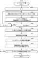
1.2.3 リークチェック方法
図2は、比較例におけるリークチェック方法の手順を示すフローチャートである。リークチェック方法は、メンテナンス作業(S10)、リークチェック(S30)の順で行われる。1.2.3 Leak Check Method FIG. 2 is a flowchart showing the steps of a leak check method in a comparative example. The leak check method is performed in the order of maintenance work (S10) and leak check (S30).
メンテナンス作業(S10)は、レーザ媒質ガスを収容する閉鎖空間を大気暴露し、その後、レーザチャンバ10の部品交換を実施し、その後、閉鎖空間を大気から隔絶することを含む。
リークチェック(S30)は、大気から隔絶された閉鎖空間にヘリウムガスを導入し、その後、閉鎖空間の外部にヘリウムガスが漏洩しているか否かを判定することを含む。The maintenance work (S10) includes exposing the closed space containing the laser medium gas to the atmosphere, then replacing parts of the
The leak check (S30) includes introducing helium gas into a closed space isolated from the atmosphere, and then determining whether helium gas is leaking to the outside of the closed space.
図3は、閉鎖空間の範囲を説明する図である。図3は、図1に示されるレーザ装置1のうちのレーザチャンバ10と各種配管とを抜粋して示しており、閉鎖空間となるレーザチャンバ10及び配管の範囲を破線で示している。閉鎖空間は、配管331、332、351、371、372の各一部の内部の空間と、配管333、334、352、及び353の各内部の空間と、レーザチャンバ10の内部の空間と、を含む。
FIG. 3 is a diagram illustrating the range of a closed space. FIG. 3 shows an excerpt of the
1.2.3.1 メンテナンス作業
図4は、比較例におけるメンテナンス作業の手順を示すフローチャートである。図4のフローチャートは、図2のS10のサブルーチンに相当する。図4に示される手順のうち、実線の枠で囲まれたステップはガス制御部32の動作を示し、破線の枠で囲まれたステップは作業者の動作を示す。
レーザチャンバ10のメンテナンスにおいては、閉鎖空間を大気暴露する前に、以下の工程により閉鎖空間の内部のフッ素ガスが除去される。1.2.3.1 Maintenance Work FIG. 4 is a flowchart showing the procedure of maintenance work in a comparative example. The flowchart in FIG. 4 corresponds to the subroutine of S10 in FIG. Among the steps shown in FIG. 4, the steps surrounded by a solid line frame indicate the operations of the gas control unit 32, and the steps surrounded by a broken line frame indicate the operations of the operator.
In maintenance of the
S11において、ガス制御部32は、ガス排気の繰返し回数をカウントするためのカウンタNの値を初期値1にセットする。
S12において、ガス制御部32は、閉鎖空間の内部のガスを、フッ素トラップ37aを介して排気する。具体的には、バルブF2-V1、B-V1、及びL-V1を閉状態としたまま、バルブEX-V1及びEX-V2を開状態とする。これにより、レーザチャンバ10の内部のガスがバルブEX-V1を介して排気装置37に流れ、配管331、332、333、334、351、352、及び353の内部のガスがバルブEX-V2を介して排気装置37に流れる。排気装置37において、フッ素トラップ37aがフッ素ガス及びフッ素の化合物を捕捉する。フッ素トラップ37aを通過したガスは、排気ポンプ37b又は図示しないバイパス流路を介してレーザ装置1の外部に排気される。排気ポンプ37bを駆動した場合には、閉鎖空間の内部のガス圧が大気圧未満となるように排気することができる。In S11, the gas control unit 32 sets the value of a counter N for counting the number of times gas exhaust is repeated to an
In S12, the gas control unit 32 exhausts the gas inside the closed space via the
S13において、ガス制御部32は、閉鎖空間にヘリウムガスを導入する。具体的には、バルブF2-V1及びB-V1を閉状態としたまま、排気ポンプ37bの駆動を停止させ、バルブEX-V1及びEX-V2を閉状態とし、バルブL-V1を開状態とする。これにより、配管351から、配管352、353、331、332、333、及び334を介してレーザチャンバ10にヘリウムガスが導入される。配管371及び372の各一部にもヘリウムガスが導入される。こうして、ヘリウムガスによる閉鎖空間のガスパージが行われる。ヘリウムガスの導入後、ガス制御部32は、バルブL-V1を閉状態とする。
In S13, the gas control unit 32 introduces helium gas into the closed space. Specifically, driving of the
S14において、ガス制御部32は、カウンタNの値が所定値Nmaxに達したか否かを判定する。所定値Nmaxは、2以上の整数である。
カウンタNの値が所定値Nmaxに達していない場合(S14:NO)、ガス制御部32は、S15に処理を進める。S15において、ガス制御部32は、カウンタNの値に1を加算してNの値を更新する。S15の後、ガス制御部32は、S12に処理を戻す。ガスの排気とヘリウムガスの導入とを複数回繰り返すことにより、レーザチャンバ10の内部の空間を含む閉鎖空間のフッ素ガスが、大気暴露可能な濃度にまで除去される。
カウンタNの値が所定値Nmaxに達した場合(S14:YES)、ガス制御部32は、S16に処理を進める。In S14, the gas control unit 32 determines whether the value of the counter N has reached a predetermined value Nmax. The predetermined value Nmax is an integer of 2 or more.
If the value of the counter N has not reached the predetermined value Nmax (S14: NO), the gas control unit 32 advances the process to S15. In S15, the gas control unit 32 adds 1 to the value of the counter N to update the value of N. After S15, the gas control unit 32 returns the process to S12. By repeating gas exhaust and helium gas introduction multiple times, the fluorine gas in the closed space, including the space inside the
When the value of the counter N reaches the predetermined value Nmax (S14: YES), the gas control unit 32 advances the process to S16.
S16において、ガス制御部32は、フッ素ガスの除去完了を外部に通知する。例えば、ガス制御部32は、フッ素ガスの除去完了を示す信号をレーザ制御部30に送信する。この信号を契機として、レーザ制御部30はFDCシステム120にフッ素ガスの除去完了を示す通知を送信する。FDCシステム120への通知に加えて、又はFDCシステム120への通知に代えて、レーザ制御部30はユーザインターフェース140にフッ素ガスの除去完了を示す表示を行わせる。
In S16, the gas control unit 32 notifies the outside of the completion of fluorine gas removal. For example, the gas control unit 32 transmits a signal indicating completion of fluorine gas removal to the laser control unit 30. Taking this signal as a trigger, the laser control unit 30 transmits a notification to the
S17において、作業者は、レーザチャンバ10の部品交換を実施するために閉鎖空間を大気暴露する。例えば、ウインドウ10a又は10bの交換作業を行う場合、レーザチャンバ10の内部の空間の少なくとも一部が大気暴露される。また例えば、レーザチャンバ10自体の交換作業を行う場合、レーザチャンバ10に接続された配管334、371の一部等も大気暴露される。S18において、作業者は、レーザチャンバ10の部品交換を実施する。
In S17, the operator exposes the closed space to the atmosphere in order to replace parts of the
S19において、作業者は、閉鎖空間を大気から隔絶し、さらに、ユーザインターフェース140を介してメンテナンス作業の完了を入力する。レーザ制御部30は、ユーザインターフェース140に入力された信号を受信し、メンテナンス作業の完了を示す信号をガス制御部32に送信する。
At S19, the operator isolates the closed space from the atmosphere and further inputs via the
S20において、ガス制御部32は、メンテナンス作業の完了を示す信号を受信したか否かを判定する。メンテナンス作業の完了を示す信号を受信していない場合(S20:NO)、ガス制御部32は、メンテナンス作業の完了を示す信号を受信するまで待機する。メンテナンス作業の完了を示す信号を受信した場合(S20:YES)、ガス制御部32は、本フローチャートの処理を終了し、図2に示される処理に戻る。 In S20, the gas control unit 32 determines whether a signal indicating the completion of the maintenance work has been received. If the signal indicating the completion of the maintenance work has not been received (S20: NO), the gas control unit 32 waits until it receives the signal indicating the completion of the maintenance work. If a signal indicating the completion of the maintenance work is received (S20: YES), the gas control unit 32 ends the process of this flowchart and returns to the process shown in FIG. 2.
1.2.3.2 リークチェック
図5は、比較例におけるリークチェックの手順を示すフローチャートである。図5のフローチャートは、図2のS30のサブルーチンに相当する。図5に示される手順のうち、実線の枠で囲まれたステップはガス制御部32の動作を示し、破線の枠で囲まれたステップは作業者の動作を示す。1.2.3.2 Leak Check FIG. 5 is a flowchart showing the leak check procedure in the comparative example. The flowchart in FIG. 5 corresponds to the subroutine of S30 in FIG. Among the steps shown in FIG. 5, the steps surrounded by a solid line frame indicate the operations of the gas control unit 32, and the steps surrounded by a broken line frame indicate the operations of the operator.
S32において、ガス制御部32は、バルブL-V1を開状態とし、閉鎖空間にヘリウムガスを導入する。このとき、バルブF2-V1、B-V1、EX-V1、及びEX-V2は閉状態とされる。 In S32, the gas control unit 32 opens the valve L-V1 and introduces helium gas into the closed space. At this time, valves F2-V1, B-V1, EX-V1, and EX-V2 are closed.
S33において、ガス制御部32は、圧力計Pで計測されるレーザチャンバ10の内部のガス圧が所定値に達したか否かを判定する。レーザチャンバ10の内部のガス圧が所定値に達していない場合(S33:NO)、ガス制御部32は、レーザチャンバ10の内部のガス圧が所定値に達するまで待機する。レーザチャンバ10の内部のガス圧が所定値に達した場合(S33:YES)、ガス制御部32は、S34に処理を進める。
In S33, the gas control unit 32 determines whether the gas pressure inside the
S34において、ガス制御部32は、バルブL-V1を閉状態とし、ガスの充填完了を外部に通知する。例えば、ガス制御部32は、ガスの充填完了を示す信号をレーザ制御部30に送信し、レーザ制御部30が、FDCシステム120にガスの充填完了を示す通知を送信し、及び/又はユーザインターフェース140にガスの充填完了を示す表示を行わせる。
In S34, the gas control unit 32 closes the valve L-V1 and notifies the outside that gas filling is complete. For example, the gas controller 32 may send a signal to the laser controller 30 indicating that gas filling is complete, the laser controller 30 may send a notification to the
S35において、作業者が、図示しないヘリウムリークディテクターを用いて、閉鎖空間の外部にヘリウムガスが漏洩しているか否かを判定する。例えば、ウインドウ10a又は10bを交換した場合には、交換したウインドウの周囲でヘリウムガスが漏洩しているか否かを調べる。その後、作業者は、ユーザインターフェース140を介して判定結果を入力する。レーザ制御部30は、ユーザインターフェース140に入力された信号を受信し、判定結果を示す信号をガス制御部32に送信する。あるいは、ヘリウムリークディテクターからレーザ制御部30に判定結果を示す信号が送信され、レーザ制御部30が、この信号をガス制御部32に送信するようになっていてもよい。
In S35, the operator uses a helium leak detector (not shown) to determine whether helium gas is leaking to the outside of the closed space. For example, when the
S36において、ガス制御部32は、閉鎖空間の外部にヘリウムガスが漏洩しているか否かの判定結果を識別する。 In S36, the gas control unit 32 identifies the determination result as to whether helium gas is leaking to the outside of the closed space.
閉鎖空間の外部にヘリウムガスが漏洩している場合(S36:YES)、ガス制御部32は、本フローチャートの処理を終了し、図2に示される処理に戻る。このとき、ガス制御部32は、レーザ制御部30に装置エラーを示す信号を送信してもよい。レーザ制御部30は、FDCシステム120に装置エラーを示す通知を送信し、及び/又はユーザインターフェース140に装置エラーを示す表示を行わせてもよい。
If helium gas is leaking to the outside of the closed space (S36: YES), the gas control unit 32 ends the process of this flowchart and returns to the process shown in FIG. 2. At this time, the gas control section 32 may transmit a signal indicating an apparatus error to the laser control section 30. Laser controller 30 may send a notification to
閉鎖空間の外部にヘリウムガスが漏洩していない場合(S36:NO)、ガス制御部32は、S37に処理を進める。S37において、ガス制御部32は、閉鎖空間の内部のガスを排気する。排気の手順は図4のS12において説明したものと同様でよい。その後、S38において、ガス制御部32は、レーザチャンバ10の内部の空間を含む閉鎖空間にネオン含有ガスとフッ素含有ガスとを導入する。具体的には、まず、バルブEX-V1、EX-V2、F2-V1、及びL-V1を閉状態とし、バルブB-V1を開状態とする。これにより、配管332からレーザチャンバ10にネオン含有ガスが導入される。次に、バルブEX-V1、EX-V2、B-V1、L-V1を閉状態とし、バルブF2-V1を開状態とする。これにより、配管331からレーザチャンバ10にフッ素含有ガスが導入される。
If helium gas has not leaked to the outside of the closed space (S36: NO), the gas control unit 32 advances the process to S37. In S37, the gas control unit 32 exhausts the gas inside the closed space. The evacuation procedure may be the same as that described in S12 of FIG. After that, in S38, the gas control unit 32 introduces the neon-containing gas and the fluorine-containing gas into the closed space including the space inside the
レーザチャンバ10の内部のガス圧及びフッ素ガス濃度が所望の値になったら、ガス制御部32は、バルブEX-V1、EX-V2、F2-V1、B-V1、及びL-V1を閉状態とし、レーザ装置1の稼働準備完了を示す信号をレーザ制御部30に送信する。
あるいは、レーザチャンバ10の内部のガス組成を安定化するために、S37の排気とS38のガス導入とを複数回繰返した後、レーザ装置1の稼働準備完了を示す信号をレーザ制御部30に送信してもよい。
S38の後、ガス制御部32は、本フローチャートの処理を終了し、図2に示される処理に戻る。When the gas pressure and fluorine gas concentration inside the
Alternatively, in order to stabilize the gas composition inside the
After S38, the gas control unit 32 ends the process of this flowchart and returns to the process shown in FIG. 2.
1.3 比較例の課題
比較例においては、ヘリウムガスを用いて閉鎖空間のガスパージとリークチェックが行われている。しかし、ヘリウムガスは産出地及び産出量が限られているため、調達が困難となったり価格が高騰したりする場合がある。仮にヘリウムガスの調達が止まった場合には、レーザ装置1のメンテナンスができなくなり、レーザ装置1を稼働できなくなる可能性がある。1.3 Issues of Comparative Example In the comparative example, helium gas was used to purge the closed space and check for leaks. However, because helium gas is produced in limited areas and in limited quantities, it may be difficult to procure or the price may rise. If the supply of helium gas were to stop, maintenance of the
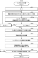
2.ネオン含有ガスを用いてリークチェックを行うレーザ装置
2.1 構成
図6~図8を用いて第1の実施形態について説明する。
図6は、第1の実施形態に係るレーザ装置1の構成を概略的に示す。第1の実施形態において、ヘリウムガスボンベ25はなくてもよい。配管351は、ネオンガスを含みフッ素含有ガスよりもフッ素ガス濃度の低い第3のガスを、レーザチャンバ10と、配管331及び332とに導入するように構成されている。配管351は、本開示における第3の配管に相当する。2. Laser device that performs leak check using neon-containing gas 2.1 Configuration The first embodiment will be described using FIGS. 6 to 8.
FIG. 6 schematically shows the configuration of the
第3のガスは、好ましくは、ネオン含有ガスと同組成のガスである。同組成のガスとは、成分とその混合比率とのいずれもが等しいガスをいう。さらに好ましくは、配管351の第1の端部は、ネオン含有ガスボンベ24に接続される。ネオン含有ガスボンベ24には配管242が接続される。配管242は、分岐部24aにおいて配管243と配管244とに分岐する。配管243が配管332の第1の端部に接続され、配管244が配管351の第1の端部に接続される。配管242、243、及び244は、本開示における第4の配管に相当する。
他の点については、第1の実施形態の構成は比較例の構成と同様である。The third gas preferably has the same composition as the neon-containing gas. Gases with the same composition refer to gases in which both the components and their mixing ratios are the same. More preferably, the first end of the
In other respects, the configuration of the first embodiment is similar to the configuration of the comparative example.
2.2 動作
第1の実施形態におけるレーザ発振器の動作及び光学モジュールパージガス供給装置39の動作は、上述の比較例において説明したものと同様である。第1の実施形態におけるリークチェック方法は、図2を参照しながら説明したのと同様の手順で行われる。但し、以下に説明するサブルーチンが、第1の実施形態と比較例とで異なっている。2.2 Operation The operation of the laser oscillator and the operation of the optical module purge gas supply device 39 in the first embodiment are similar to those described in the above-mentioned comparative example. The leak check method in the first embodiment is performed in the same procedure as described with reference to FIG. However, the subroutines described below are different between the first embodiment and the comparative example.
2.2.1 メンテナンス作業
図7は、第1の実施形態におけるメンテナンス作業の手順を示すフローチャートである。図4のS13の代わりに、図7のS13aにおいて、ガス制御部32は、閉鎖空間にネオン含有ガスを導入する。
他の点については、図7の処理は図4を参照しながら説明した比較例の処理と同様である。2.2.1 Maintenance Work FIG. 7 is a flowchart showing the procedure of maintenance work in the first embodiment. In place of S13 in FIG. 4, in S13a in FIG. 7, the gas control unit 32 introduces neon-containing gas into the closed space.
In other respects, the process in FIG. 7 is similar to the process in the comparative example described with reference to FIG.
2.2.2 リークチェック
図8は、第1の実施形態におけるリークチェックの手順を示すフローチャートである。図5のS32の代わりに、図8のS32aにおいて、ガス制御部32は、閉鎖空間にネオン含有ガスを導入する。また、図5のS35の代わりに、図8のS35aにおいて、作業者が、ネオンガスに感度を持つ図示しないリークディテクターを用いて、閉鎖空間の外部にネオンガスが漏洩しているか否かを判定する。例えば、所定の閾値より多いネオンガスが検出された場合に、閉鎖空間の外部にネオンガスが漏洩していると判定する。ネオンガスに感度を持つリークディテクターは、例えば、リファレンスガスと測定ガスとの間の熱伝導率の違いを検知することによりネオンガスを検出する装置であってもよい。リークディテクターは、ネオンガスの検出量に基づく表示又は警報を出力するように構成されていてもよい。
他の点については、図8の処理は図5を参照しながら説明した比較例の処理と同様である。2.2.2 Leak Check FIG. 8 is a flowchart showing the leak check procedure in the first embodiment. Instead of S32 in FIG. 5, in S32a in FIG. 8, the gas control unit 32 introduces neon-containing gas into the closed space. Further, instead of S35 in FIG. 5, in S35a in FIG. 8, the operator uses a leak detector (not shown) sensitive to neon gas to determine whether neon gas is leaking to the outside of the closed space. For example, if more neon gas than a predetermined threshold is detected, it is determined that neon gas is leaking to the outside of the closed space. A leak detector sensitive to neon gas may be, for example, a device that detects neon gas by detecting a difference in thermal conductivity between a reference gas and a measurement gas. The leak detector may be configured to output a display or alarm based on the detected amount of neon gas.
In other respects, the process in FIG. 8 is similar to the process in the comparative example described with reference to FIG.
2.3 作用
(1)第1の実施形態によれば、閉鎖空間にネオンガスを含むネオン含有ガスを導入し(図8のS32a)、閉鎖空間の外部にネオンガスが漏洩しているか否かを判定する(図8のS35a)。これにより、ヘリウムガスを使わなくてもリークチェックが可能となるので、ヘリウムガスの調達が困難となった場合でもレーザ装置1がメンテナンス不能により稼働停止となることを抑制し得る。2.3 Effects (1) According to the first embodiment, a neon-containing gas containing neon gas is introduced into the closed space (S32a in FIG. 8), and it is determined whether neon gas is leaking to the outside of the closed space. (S35a in FIG. 8). This makes it possible to check for leaks without using helium gas, so even if it becomes difficult to procure helium gas, it is possible to prevent the
(2)第1の実施形態によれば、閉鎖空間を大気暴露する前に、閉鎖空間の内部のガスを、フッ素トラップ37aを介して排気し(図7のS12)、閉鎖空間にネオン含有ガスを導入し(図7のS13a)、閉鎖空間の内部のガスを、フッ素トラップ37aを介して再度排気する(図7のS12)。これにより、ヘリウムガスを使わなくても閉鎖空間の内部をガスパージしてフッ素ガス濃度を低減することができる。また、リークチェックに用いられるガスと同じネオン含有ガスを用いてガスパージするので、配管の増加が抑制される。
(2) According to the first embodiment, before exposing the closed space to the atmosphere, the gas inside the closed space is exhausted via the
(3)第1の実施形態によれば、ネオンガスに感度を持つリークディテクターを用いて、閉鎖空間の外部にネオンガスが漏洩しているか否かを判定する(図8のS35a)。これにより、ネオン含有ガスをレーザチャンバ10内に導入してすぐにリークチェックすることができる。
(3) According to the first embodiment, a leak detector sensitive to neon gas is used to determine whether neon gas is leaking to the outside of the closed space (S35a in FIG. 8). Thereby, a leak check can be performed immediately after introducing the neon-containing gas into the
(4)第1の実施形態によれば、閉鎖空間の外部にネオンガスが漏洩していないと判定された場合に、閉鎖空間の内部のガスを排気し(図8のS37)、閉鎖空間にネオン含有ガス及びフッ素含有ガスを導入する(図8のS38)。これにより、ネオンガスが漏洩していないことを事前に判定するので、フッ素含有ガス等を導入したときにフッ素ガスが漏洩することを抑制し得る。また、ヘリウムガスを用いてリークチェックを行った場合と比べて、ネオン含有ガスを用いてリークチェックを行った場合にはS37の排気とS38のガス導入との繰返し回数を低減し得る。 (4) According to the first embodiment, when it is determined that neon gas has not leaked to the outside of the closed space, the gas inside the closed space is exhausted (S37 in FIG. 8), and neon gas is released into the closed space. A containing gas and a fluorine-containing gas are introduced (S38 in FIG. 8). As a result, it is determined in advance that neon gas is not leaking, so that leakage of fluorine gas can be suppressed when fluorine-containing gas or the like is introduced. Furthermore, compared to the case where a leak check is performed using helium gas, when a leak check is performed using a neon-containing gas, the number of times that exhausting in S37 and gas introduction in S38 are repeated can be reduced.
(5)第1の実施形態によれば、レーザ装置1は、レーザチャンバ10にネオンガスとフッ素ガスとを含むフッ素含有ガスを導入する配管331と、レーザチャンバ10にネオンガスを含みフッ素含有ガスよりもフッ素ガス濃度の低いネオン含有ガスを導入する配管332と、レーザチャンバ10と配管331とに、ネオンガスを含みフッ素含有ガスよりもフッ素ガス濃度の低い第3のガスを導入する配管351と、を含む。これにより、ヘリウムガスを使わなくても、ネオンガスを含む第3のガスを用いてリークチェックが可能となるので、ヘリウムガスの調達が困難となった場合でもレーザ装置1がメンテナンス不能により稼働停止となることを抑制し得る。
(5) According to the first embodiment, the
なお、第3のガスが配管351を介して導入される場合について説明したが、本開示はこれに限定されない。配管351がなくても、ネオン含有ガスと同組成の第3のガスが配管332を介して導入されてもよい。
Note that although a case has been described in which the third gas is introduced through the
(6)第1の実施形態によれば、配管351は、レーザチャンバ10と配管331とにネオン含有ガスと同組成の第3のガスを導入する。これにより、リークチェックのための第3のガスとして、レーザ媒質ガスを構成するネオン含有ガスを流用できるので、ガスの調達品目数を低減できる。また、第3のガスの配管工事のコストを削減することができる。
(6) According to the first embodiment, the
(7)第1の実施形態によれば、配管331はフッ素含有ガスを収容したフッ素含有ガスボンベ23に接続され、配管332及び351はネオン含有ガスを収容したネオン含有ガスボンベ24に接続される。
また第1の実施形態によれば、配管332及び351とネオン含有ガスボンベ24との間に、分岐部24aを含む配管242、243、及び244が接続される。
これにより、配管332及び351に接続されるガスボンベを共通化できる。また、ヘリウムガスの配管を不要とし、配管工事のコストを削減することができる。(7) According to the first embodiment, the
Further, according to the first embodiment, the
Thereby, the gas cylinders connected to the
(8)第1の実施形態によれば、配管351は、レーザチャンバ10と配管331及び332とに第3のガスを導入する。これにより、レーザチャンバ10だけでなく配管331及び332等も同時にリークチェックすることができる。
(8) According to the first embodiment, the
(9)第1の実施形態によれば、レーザ装置1は、レーザチャンバ10と配管331とからガスを排気する排気装置37を含む。これにより、排気されたレーザチャンバ10及び配管331に第3のガスを導入してリークチェックすることができる。
(9) According to the first embodiment, the
(10)第1の実施形態によれば、レーザ装置1は、レーザチャンバ10と配管331及び332とからガスを排気する排気装置37を含む。これにより、排気されたレーザチャンバ10と配管331及び332とに第3のガスを導入してリークチェックすることができる。
(10) According to the first embodiment, the
3.ガス圧の変化によりリークチェックを行うレーザ装置
図9を用いて第2の実施形態について説明する。第2の実施形態の構成は、第1の実施形態の構成と同様である。第2の実施形態の動作は、以下に説明するリークチェックのサブルーチンにおいて、第1の実施形態の動作と異なっている。3. Laser device that performs leak check by changing gas pressure A second embodiment will be described using FIG. 9. The configuration of the second embodiment is similar to that of the first embodiment. The operation of the second embodiment differs from that of the first embodiment in the leak check subroutine described below.
図9は、第2の実施形態におけるリークチェックの手順を示すフローチャートである。図8のS35aの代わりに、図9のS35bにおいて、ガス制御部32が、一定期間Tにおけるレーザチャンバ10の内部のガス圧の変化を検出することにより、閉鎖空間の外部にネオン含有ガスが漏洩しているか否かを判定する。
FIG. 9 is a flowchart showing the leak check procedure in the second embodiment. Instead of S35a in FIG. 8, in S35b in FIG. 9, the gas control unit 32 detects a change in the gas pressure inside the
例えば、ガス制御部32は、圧力計Pによって測定されるレーザチャンバ10の内部のガス圧P1をレーザ制御部30から受信し、さらに一定期間Tが経過したときのガス圧P2をレーザ制御部30から受信する。そして、ガス制御部32は、以下の値ΔP又はdP/dTを算出する。
ΔP=|P1-P2|
dP/dT=|P1-P2|/TFor example, the gas control unit 32 receives the gas pressure P1 inside the
ΔP=|P1-P2|
dP/dT=|P1-P2|/T
ガス制御部32は、ΔPが所定の閾値以下である場合、あるいはdP/dTが所定の閾値以下である場合、閉鎖空間の外部にネオン含有ガスが漏洩していないと判定する。ガス制御部32は、ΔPが所定の閾値より大きい場合、あるいはdP/dTが所定の閾値より大きい場合、閉鎖空間の外部にネオン含有ガスが漏洩していると判定する。
他の点については、第2の実施形態の動作は第1の実施形態の動作と同様である。The gas control unit 32 determines that neon-containing gas is not leaking to the outside of the closed space when ΔP is less than or equal to a predetermined threshold, or when dP/dT is less than or equal to a predetermined threshold. The gas control unit 32 determines that neon-containing gas is leaking to the outside of the closed space when ΔP is larger than a predetermined threshold or when dP/dT is larger than a predetermined threshold.
In other respects, the operation of the second embodiment is similar to that of the first embodiment.
第2の実施形態によれば、閉鎖空間の内部のガス圧の変化を検出して、閉鎖空間の外部にネオン含有ガスが漏洩しているか否かを判定する(図9のS35b)。これにより、リークチェックを自動化し、作業者の工数を低減できる。 According to the second embodiment, a change in gas pressure inside the closed space is detected to determine whether neon-containing gas is leaking to the outside of the closed space (S35b in FIG. 9). This makes it possible to automate leak checks and reduce worker man-hours.
4.交換用レーザチャンバのリークチェックを行うレーザ装置
図10及び図11を用いて第3の実施形態について説明する。第3の実施形態の構成は、第1及び第2の実施形態の構成と同様である。第3の実施形態は、交換用レーザチャンバ10dのリークチェックを行う点で、第1及び第2の実施形態と異なっている。4. Laser device that performs leak check of replacement laser chamber A third embodiment will be described using FIGS. 10 and 11. The configuration of the third embodiment is similar to the configurations of the first and second embodiments. The third embodiment differs from the first and second embodiments in that a leak check of the
4.1 交換用レーザチャンバ
図10は、交換用レーザチャンバ10dの構成を概略的に示す。交換用レーザチャンバ10dは、ウインドウ10a及び10bが設けられ、電極11a及び11bを内部に収容している点でレーザチャンバ10と同様である。上述のメンテナンス作業がレーザチャンバ10の交換を含む場合には、レーザ装置1からレーザチャンバ10が取り外されて、図10に示される交換用レーザチャンバ10dがレーザ装置1に取り付けられる。4.1 Replacement Laser Chamber FIG. 10 schematically shows the configuration of the
4.2 リークチェックの手順
図11は、第3の実施形態におけるリークチェックの手順を示すフローチャートである。破線の枠で囲まれたステップはレーザ装置1の製造者の動作を示す。4.2 Leak Check Procedure FIG. 11 is a flowchart showing the leak check procedure in the third embodiment. The steps surrounded by a dashed line indicate the actions of the manufacturer of the
S1において、レーザ装置1の製造者が、レーザ装置1の製造工場において交換用レーザチャンバ10dにネオン含有ガスを封入し、図示しない記憶装置に交換用レーザチャンバ10dの内部のガス圧P1及び測定時刻T1を記憶させる。記憶装置は、例えば、交換用レーザチャンバ10dに付属する記憶装置でもよい。あるいは、記憶装置は、出荷先の半導体製造工場に設置されたレーザ装置1のガス制御部32又はレーザ制御部30からアクセス可能なネットワーク上の記憶装置でもよい。
交換用レーザチャンバ10dは、半導体製造工場に向けて出荷され、レーザ装置1のレーザチャンバ交換作業によってレーザ装置1に取り付けられる。In S1, the manufacturer of the
The
S2において、ガス制御部32は、レーザチャンバ交換作業の完了を示す信号を受信したか否かを判定する。レーザチャンバ交換作業の完了を示す信号を受信していない場合(S2:NO)、ガス制御部32は、レーザチャンバ交換作業の完了を示す信号を受信するまで待機する。レーザチャンバ交換作業の完了を示す信号を受信した場合(S2:YES)、ガス制御部32は、S3に処理を進める。 In S2, the gas control unit 32 determines whether a signal indicating completion of the laser chamber replacement work has been received. If the signal indicating the completion of the laser chamber replacement work has not been received (S2: NO), the gas control unit 32 waits until it receives the signal indicating the completion of the laser chamber replacement work. If a signal indicating completion of the laser chamber replacement work is received (S2: YES), the gas control unit 32 advances the process to S3.
S3において、ガス制御部32は、圧力計Pによって測定されるレーザチャンバ10の内部のガス圧P2及び測定時刻T2をレーザ制御部30から受信する。この場合のレーザチャンバ10は、新たに取り付けられた交換用レーザチャンバ10dである。ガス制御部32は、記憶装置に記憶されたガス圧P1及び測定時刻T1を読み出して、以下の値ΔP又はdP/dTを算出する。
ΔP=|P1-P2|
dP/dT=|P1-P2|/(T2-T1)In S3, the gas control unit 32 receives the gas pressure P2 inside the
ΔP=|P1-P2|
dP/dT=|P1-P2|/(T2-T1)
ガス制御部32は、ΔPが所定の閾値以下である場合、あるいはdP/dTが所定の閾値以下である場合、レーザチャンバ10の外部にネオン含有ガスが漏洩していないと判定する。ガス制御部32は、ΔPが所定の閾値より大きい場合、あるいはdP/dTが所定の閾値より大きい場合、レーザチャンバ10の外部にネオン含有ガスが漏洩していると判定する。
The gas control unit 32 determines that neon-containing gas is not leaking to the outside of the
S36~S38の処理は、図5を参照しながら説明した対応する処理と同様である。閉鎖空間の外部にヘリウムガスが漏洩している場合(S36:YES)、あるいはS38の後、ガス制御部32は、本フローチャートの処理を終了する。
その他の点については、第3の実施形態は、第1又は第2の実施形態と同様である。The processing in S36 to S38 is similar to the corresponding processing described with reference to FIG. If helium gas is leaking to the outside of the closed space (S36: YES), or after S38, the gas control unit 32 ends the process of this flowchart.
In other respects, the third embodiment is similar to the first or second embodiment.
4.3 作用
第3の実施形態によれば、交換用レーザチャンバ10dのリークチェックを行い(図11のS3)、その後、フッ素含有ガス等を導入する(図11のS38)。これにより、ネオンガスが漏洩していないことを事前に判定するので、フッ素含有ガス等を導入したときに交換用レーザチャンバ10dからフッ素ガスが漏洩することを抑制し得る。また、ヘリウムガスを用いてリークチェックを行った場合と比べて、ネオン含有ガスを用いてリークチェックを行った場合にはS37の排気とS38のガス導入との繰返し回数を低減し得る。4.3 Effects According to the third embodiment, a leak check of the
5.その他
上記の説明は、制限ではなく単なる例示を意図している。従って、特許請求の範囲を逸脱することなく本開示の実施形態に変更を加えることができることは、当業者には明らかである。また、本開示の実施形態を組み合わせて使用することも当業者には明らかである。5. Miscellaneous The above description is intended to be illustrative only and not limiting. It will therefore be apparent to those skilled in the art that modifications may be made to the embodiments of the disclosure without departing from the scope of the claims. It will also be apparent to those skilled in the art that the embodiments of the present disclosure may be used in combination.
本明細書及び特許請求の範囲全体で使用される用語は、明記が無い限り「限定的でない」用語と解釈されるべきである。たとえば、「含む」、「有する」、「備える」、「具備する」などの用語は、「記載されたもの以外の構成要素の存在を除外しない」と解釈されるべきである。また、修飾語「1つの」は、「少なくとも1つ」又は「1又はそれ以上」を意味すると解釈されるべきである。また、「A、B及びCの少なくとも1つ」という用語は、「A」「B」「C」「A+B」「A+C」「B+C」又は「A+B+C」と解釈されるべきである。さらに、それらと「A」「B」「C」以外のものとの組み合わせも含むと解釈されるべきである。 The terms used throughout this specification and claims should be construed as "non-limiting" terms unless explicitly stated otherwise. For example, words such as "comprising," "having," "comprising," "comprising," and the like should be construed as "does not exclude the presence of elements other than those listed." Also, the modifier "a" should be construed to mean "at least one" or "one or more." Additionally, the term "at least one of A, B, and C" should be interpreted as "A," "B," "C," "A+B," "A+C," "B+C," or "A+B+C." Furthermore, it should be interpreted to include combinations of these with other than "A," "B," and "C."
Claims (5)
ネオンガスとフッ素ガスとを含む第1のガスを収容した第1のガス供給源に接続され、前記レーザチャンバに前記第1のガスを導入する第1の配管と、
ネオンガスを含み前記第1のガスよりもフッ素ガス濃度の低い第2のガスを収容した第2のガス供給源に接続され、前記レーザチャンバに前記第2のガスを導入する第2の配管と、
を含むレーザ装置のリークチェック方法であって、
前記レーザチャンバの内部の空間を含む閉鎖空間に、前記第2のガス供給源から前記第2のガスと同組成の第3のガスを導入することと、
前記閉鎖空間の外部にネオンガスが漏洩しているか否かを判定することと、
を含む、レーザ装置のリークチェック方法。 a laser chamber;
a first pipe connected to a first gas supply source containing a first gas containing neon gas and fluorine gas, and introducing the first gas into the laser chamber;
a second pipe connected to a second gas supply source containing a second gas containing neon gas and having a lower fluorine gas concentration than the first gas, and introducing the second gas into the laser chamber; ,
A leak check method for a laser device, the method comprising:
Introducing a third gas having the same composition as the second gas from the second gas supply source into a closed space including the interior space of the laser chamber;
determining whether neon gas is leaking to the outside of the closed space;
Leak checking method for laser equipment, including:
前記閉鎖空間の内部のガスを、フッ素トラップを介して排気し、前記閉鎖空間に前記第3のガスを導入し、前記閉鎖空間の内部のガスを、前記フッ素トラップを介して再度排気することと、Exhausting the gas inside the closed space through the fluorine trap, introducing the third gas into the closed space, and exhausting the gas inside the closed space again through the fluorine trap. ,
その後、前記閉鎖空間を大気暴露することと、Thereafter, exposing the closed space to the atmosphere;
前記閉鎖空間を大気暴露した後、前記閉鎖空間を大気から隔絶することと、After exposing the closed space to the atmosphere, isolating the closed space from the atmosphere;
をさらに含み、further including;
その後、前記閉鎖空間に前記第3のガスを導入し、前記閉鎖空間の外部にネオンガスが漏洩しているか否かの前記判定を行う、リークチェック方法。Thereafter, the third gas is introduced into the closed space, and it is determined whether neon gas is leaking to the outside of the closed space.
前記判定は、ネオンガスに感度を持つリークディテクターを用いて行われる、リークチェック方法。A leak check method in which the determination is performed using a leak detector sensitive to neon gas.
前記レーザ装置が、
前記閉鎖空間に前記第3のガスを導入する第3の配管
をさらに含む、リークチェック方法。 The leak check method according to claim 1 , comprising:
The laser device
The leak check method further includes a third pipe that introduces the third gas into the closed space.
前記第2の配管及び前記第3の配管と前記第2のガス供給源との間に、分岐部を含む第4の配管が接続された、リークチェック方法。 5. The leak check method according to claim 4 ,
A leak check method, wherein a fourth pipe including a branch part is connected between the second pipe, the third pipe, and the second gas supply source.
Applications Claiming Priority (1)
| Application Number | Priority Date | Filing Date | Title |
|---|---|---|---|
| PCT/JP2019/039358 WO2021065001A1 (en) | 2019-10-04 | 2019-10-04 | Laser device and leak check method for laser device |
Publications (2)
| Publication Number | Publication Date |
|---|---|
| JPWO2021065001A1 JPWO2021065001A1 (en) | 2021-04-08 |
| JP7401552B2 true JP7401552B2 (en) | 2023-12-19 |
Family
ID=75336875
Family Applications (1)
| Application Number | Title | Priority Date | Filing Date |
|---|---|---|---|
| JP2021550928A Active JP7401552B2 (en) | 2019-10-04 | 2019-10-04 | Laser equipment and laser equipment leak check method |
Country Status (4)
| Country | Link |
|---|---|
| US (1) | US12388228B2 (en) |
| JP (1) | JP7401552B2 (en) |
| CN (1) | CN114287088B (en) |
| WO (1) | WO2021065001A1 (en) |
Families Citing this family (1)
| Publication number | Priority date | Publication date | Assignee | Title |
|---|---|---|---|---|
| DE102023106223A1 (en) * | 2023-03-13 | 2024-09-19 | TRUMPF Lasersystems for Semiconductor Manufacturing SE | Automated contamination detection |
Citations (4)
| Publication number | Priority date | Publication date | Assignee | Title |
|---|---|---|---|---|
| JP2006013232A (en) | 2004-06-28 | 2006-01-12 | Komatsu Ltd | Laser chamber regeneration processing method for ultraviolet gas laser apparatus |
| US20070030876A1 (en) | 2005-08-05 | 2007-02-08 | Levatter Jeffrey I | Apparatus and method for purging and recharging excimer laser gases |
| WO2017081819A1 (en) | 2015-11-13 | 2017-05-18 | ギガフォトン株式会社 | Laser gas purifying system and laser system |
| WO2018047280A1 (en) | 2016-09-08 | 2018-03-15 | ギガフォトン株式会社 | Laser device |
Family Cites Families (9)
| Publication number | Priority date | Publication date | Assignee | Title |
|---|---|---|---|---|
| JPH01146565U (en) | 1988-03-31 | 1989-10-09 | ||
| JPH02142558U (en) * | 1989-05-02 | 1990-12-04 | ||
| DE4208388A1 (en) * | 1992-03-16 | 1993-09-23 | Lambda Physik Gmbh | Excimer laser with supply of gas mixt. for tube filling - is safeguarded against halogen leakage by separate stopping of supplies from high-pressure halogen and inert gas cylinders |
| JP3743724B2 (en) * | 1995-10-20 | 2006-02-08 | 株式会社小松製作所 | Excimer laser device gas supply device and laser gas exchange, laser gas injection, abnormality processing method |
| JPH09283821A (en) * | 1996-04-12 | 1997-10-31 | Shibuya Kogyo Co Ltd | Laser oscillator having laser gas circulator |
| US6819699B1 (en) | 1999-03-05 | 2004-11-16 | Komatsu Ltd. | Arf excimer laser device, scanning type exposure device and ultraviolet laser device |
| US7180081B2 (en) * | 2000-06-09 | 2007-02-20 | Cymer, Inc. | Discharge produced plasma EUV light source |
| JP4156642B2 (en) * | 2006-09-04 | 2008-09-24 | ファナック株式会社 | GAS LASER DEVICE, AND Blower Monitoring Method and Monitoring Device |
| JP5044265B2 (en) | 2007-04-16 | 2012-10-10 | 光洋サーモシステム株式会社 | Heat treatment apparatus, heat treatment method, and program for heat treatment apparatus |
-
2019
- 2019-10-04 WO PCT/JP2019/039358 patent/WO2021065001A1/en not_active Ceased
- 2019-10-04 CN CN201980099848.5A patent/CN114287088B/en active Active
- 2019-10-04 JP JP2021550928A patent/JP7401552B2/en active Active
-
2022
- 2022-03-03 US US17/686,327 patent/US12388228B2/en active Active
Patent Citations (4)
| Publication number | Priority date | Publication date | Assignee | Title |
|---|---|---|---|---|
| JP2006013232A (en) | 2004-06-28 | 2006-01-12 | Komatsu Ltd | Laser chamber regeneration processing method for ultraviolet gas laser apparatus |
| US20070030876A1 (en) | 2005-08-05 | 2007-02-08 | Levatter Jeffrey I | Apparatus and method for purging and recharging excimer laser gases |
| WO2017081819A1 (en) | 2015-11-13 | 2017-05-18 | ギガフォトン株式会社 | Laser gas purifying system and laser system |
| WO2018047280A1 (en) | 2016-09-08 | 2018-03-15 | ギガフォトン株式会社 | Laser device |
Also Published As
| Publication number | Publication date |
|---|---|
| CN114287088B (en) | 2025-03-21 |
| JPWO2021065001A1 (en) | 2021-04-08 |
| CN114287088A (en) | 2022-04-05 |
| US20220190540A1 (en) | 2022-06-16 |
| US12388228B2 (en) | 2025-08-12 |
| WO2021065001A1 (en) | 2021-04-08 |
Similar Documents
| Publication | Publication Date | Title |
|---|---|---|
| US6490305B2 (en) | Beam delivery system for molecular fluorine (F2) laser | |
| JP4689064B2 (en) | Exposure apparatus and device manufacturing method | |
| JP7401552B2 (en) | Laser equipment and laser equipment leak check method | |
| US20020021729A1 (en) | Narrow bandwidth oscillator-amplifier system | |
| US6738406B2 (en) | Precision measurement of wavelengths emitted by a molecular fluorine laser at 157nm | |
| WO1999036950A1 (en) | Exposure system, exposure apparatus, and coating developing exposure apparatus | |
| US6839372B2 (en) | Gas discharge ultraviolet laser with enclosed beam path with added oxidizer | |
| US6700916B1 (en) | E-diagnostic, laser simulator, automated testing and deconvolution of spectra for lithographic exposure radiation generating systems such as excimer or molecular fluorine laser or EUV source systems | |
| WO2017072879A1 (en) | Line-narrowing excimer laser device | |
| US20020021731A1 (en) | Electrostatic precipitator corona discharge ignition voltage probe for gas status detection and control system for gas discharge lasers | |
| US6553042B2 (en) | Laser apparatus for generating vacuum ultraviolet narrow-band laser beams | |
| US10971886B2 (en) | Laser apparatus | |
| CN111670520B (en) | Laser gas management system, manufacturing method of electronic device, and abnormality determination method of excimer laser system | |
| US6763048B2 (en) | Line narrowing of molecular fluorine laser emission | |
| US6792023B1 (en) | Method and apparatus for reduction of spectral fluctuations | |
| US12341313B2 (en) | Gas laser apparatus, laser beam emitting method of gas laser apparatus, and electronic device manufacturing method | |
| US6839375B1 (en) | On-line quality control of the key optical components in lithography lasers using laser induced fluorescence | |
| US20030095580A1 (en) | Beam delivery system for lithographic exposure radiation source | |
| JP2002057089A (en) | Exposure equipment | |
| JP4532660B2 (en) | Exposure equipment | |
| US7253905B2 (en) | Determination and correction for laser induced CCD camera degradation | |
| JP4077592B2 (en) | Impurity concentration measuring device for laser equipment | |
| JP4094772B2 (en) | Fluorine laser equipment | |
| JP4148488B2 (en) | Ultraviolet laser device and gas supply method for ultraviolet laser device | |
| JPH05167135A (en) | Excimer laser device |
Legal Events
| Date | Code | Title | Description |
|---|---|---|---|
| A621 | Written request for application examination |
Free format text: JAPANESE INTERMEDIATE CODE: A621 Effective date: 20220909 |
|
| A131 | Notification of reasons for refusal |
Free format text: JAPANESE INTERMEDIATE CODE: A131 Effective date: 20230704 |
|
| A521 | Request for written amendment filed |
Free format text: JAPANESE INTERMEDIATE CODE: A523 Effective date: 20230828 |
|
| TRDD | Decision of grant or rejection written | ||
| A01 | Written decision to grant a patent or to grant a registration (utility model) |
Free format text: JAPANESE INTERMEDIATE CODE: A01 Effective date: 20231114 |
|
| A61 | First payment of annual fees (during grant procedure) |
Free format text: JAPANESE INTERMEDIATE CODE: A61 Effective date: 20231207 |
|
| R150 | Certificate of patent or registration of utility model |
Ref document number: 7401552 Country of ref document: JP Free format text: JAPANESE INTERMEDIATE CODE: R150 |