JP7401448B2 - Optical reaction wells for assay devices - Google Patents
Optical reaction wells for assay devices Download PDFInfo
- Publication number
- JP7401448B2 JP7401448B2 JP2020550666A JP2020550666A JP7401448B2 JP 7401448 B2 JP7401448 B2 JP 7401448B2 JP 2020550666 A JP2020550666 A JP 2020550666A JP 2020550666 A JP2020550666 A JP 2020550666A JP 7401448 B2 JP7401448 B2 JP 7401448B2
- Authority
- JP
- Japan
- Prior art keywords
- fluid
- chamber
- sample
- plug
- volume
- Prior art date
- Legal status (The legal status is an assumption and is not a legal conclusion. Google has not performed a legal analysis and makes no representation as to the accuracy of the status listed.)
- Active
Links
- 238000003556 assay Methods 0.000 title claims description 392
- 230000003287 optical effect Effects 0.000 title description 40
- 238000006243 chemical reaction Methods 0.000 title description 5
- 239000012530 fluid Substances 0.000 claims description 896
- 239000003153 chemical reaction reagent Substances 0.000 claims description 155
- 238000000034 method Methods 0.000 claims description 105
- 238000011049 filling Methods 0.000 claims description 72
- 239000012528 membrane Substances 0.000 claims description 70
- 239000000758 substrate Substances 0.000 claims description 68
- 238000002156 mixing Methods 0.000 claims description 63
- 230000005499 meniscus Effects 0.000 claims description 54
- 230000037361 pathway Effects 0.000 claims description 46
- 238000004891 communication Methods 0.000 claims description 28
- 238000007789 sealing Methods 0.000 claims description 23
- 238000002844 melting Methods 0.000 claims description 13
- 230000008018 melting Effects 0.000 claims description 13
- 230000007423 decrease Effects 0.000 claims description 8
- 230000005484 gravity Effects 0.000 claims description 8
- 239000000523 sample Substances 0.000 description 477
- 239000007789 gas Substances 0.000 description 24
- 238000002474 experimental method Methods 0.000 description 17
- 238000001228 spectrum Methods 0.000 description 17
- 230000015572 biosynthetic process Effects 0.000 description 11
- 238000002788 crimping Methods 0.000 description 11
- 230000033001 locomotion Effects 0.000 description 10
- 230000005284 excitation Effects 0.000 description 9
- 150000007523 nucleic acids Chemical class 0.000 description 9
- 239000000126 substance Substances 0.000 description 9
- 239000000463 material Substances 0.000 description 8
- 239000000203 mixture Substances 0.000 description 7
- 102000039446 nucleic acids Human genes 0.000 description 7
- 108020004707 nucleic acids Proteins 0.000 description 7
- 230000008859 change Effects 0.000 description 6
- 230000008569 process Effects 0.000 description 6
- 230000003321 amplification Effects 0.000 description 5
- 238000004166 bioassay Methods 0.000 description 5
- 238000004090 dissolution Methods 0.000 description 5
- 238000010438 heat treatment Methods 0.000 description 5
- 238000003199 nucleic acid amplification method Methods 0.000 description 5
- 230000002829 reductive effect Effects 0.000 description 5
- 238000013459 approach Methods 0.000 description 4
- 230000005540 biological transmission Effects 0.000 description 4
- 239000013641 positive control Substances 0.000 description 4
- 238000005063 solubilization Methods 0.000 description 4
- 230000007928 solubilization Effects 0.000 description 4
- 238000003466 welding Methods 0.000 description 4
- 238000001514 detection method Methods 0.000 description 3
- 230000001788 irregular Effects 0.000 description 3
- 238000004020 luminiscence type Methods 0.000 description 3
- 239000000243 solution Substances 0.000 description 3
- 238000012360 testing method Methods 0.000 description 3
- 238000011144 upstream manufacturing Methods 0.000 description 3
- XLYOFNOQVPJJNP-UHFFFAOYSA-N water Chemical compound O XLYOFNOQVPJJNP-UHFFFAOYSA-N 0.000 description 3
- XKRFYHLGVUSROY-UHFFFAOYSA-N Argon Chemical compound [Ar] XKRFYHLGVUSROY-UHFFFAOYSA-N 0.000 description 2
- IJGRMHOSHXDMSA-UHFFFAOYSA-N Atomic nitrogen Chemical compound N#N IJGRMHOSHXDMSA-UHFFFAOYSA-N 0.000 description 2
- 150000001413 amino acids Chemical class 0.000 description 2
- 239000003054 catalyst Substances 0.000 description 2
- 238000011109 contamination Methods 0.000 description 2
- 230000012447 hatching Effects 0.000 description 2
- 230000000670 limiting effect Effects 0.000 description 2
- 239000007788 liquid Substances 0.000 description 2
- 238000011068 loading method Methods 0.000 description 2
- 239000000178 monomer Substances 0.000 description 2
- 238000001668 nucleic acid synthesis Methods 0.000 description 2
- 239000002777 nucleoside Substances 0.000 description 2
- 239000002773 nucleotide Substances 0.000 description 2
- 125000003729 nucleotide group Chemical group 0.000 description 2
- 238000010647 peptide synthesis reaction Methods 0.000 description 2
- 229920000642 polymer Polymers 0.000 description 2
- 108090000765 processed proteins & peptides Proteins 0.000 description 2
- 230000004044 response Effects 0.000 description 2
- 230000000717 retained effect Effects 0.000 description 2
- 238000000926 separation method Methods 0.000 description 2
- 238000004904 shortening Methods 0.000 description 2
- 238000003786 synthesis reaction Methods 0.000 description 2
- 238000005382 thermal cycling Methods 0.000 description 2
- 238000012546 transfer Methods 0.000 description 2
- 102000004190 Enzymes Human genes 0.000 description 1
- 108090000790 Enzymes Proteins 0.000 description 1
- 102100034343 Integrase Human genes 0.000 description 1
- 108010092799 RNA-directed DNA polymerase Proteins 0.000 description 1
- 238000011529 RT qPCR Methods 0.000 description 1
- 230000006978 adaptation Effects 0.000 description 1
- 238000004026 adhesive bonding Methods 0.000 description 1
- 229910052786 argon Inorganic materials 0.000 description 1
- QVGXLLKOCUKJST-UHFFFAOYSA-N atomic oxygen Chemical compound [O] QVGXLLKOCUKJST-UHFFFAOYSA-N 0.000 description 1
- 239000011324 bead Substances 0.000 description 1
- 238000007398 colorimetric assay Methods 0.000 description 1
- 230000008094 contradictory effect Effects 0.000 description 1
- 238000007796 conventional method Methods 0.000 description 1
- 230000001419 dependent effect Effects 0.000 description 1
- 238000010586 diagram Methods 0.000 description 1
- 238000009792 diffusion process Methods 0.000 description 1
- 238000006073 displacement reaction Methods 0.000 description 1
- 238000009826 distribution Methods 0.000 description 1
- 230000000694 effects Effects 0.000 description 1
- 238000006911 enzymatic reaction Methods 0.000 description 1
- 230000007717 exclusion Effects 0.000 description 1
- 238000005429 filling process Methods 0.000 description 1
- 238000011010 flushing procedure Methods 0.000 description 1
- 239000012456 homogeneous solution Substances 0.000 description 1
- 238000003384 imaging method Methods 0.000 description 1
- 239000011261 inert gas Substances 0.000 description 1
- 238000002347 injection Methods 0.000 description 1
- 239000007924 injection Substances 0.000 description 1
- 238000003780 insertion Methods 0.000 description 1
- 230000037431 insertion Effects 0.000 description 1
- 238000011901 isothermal amplification Methods 0.000 description 1
- 239000000155 melt Substances 0.000 description 1
- 238000012986 modification Methods 0.000 description 1
- 230000004048 modification Effects 0.000 description 1
- 229910052757 nitrogen Inorganic materials 0.000 description 1
- -1 nucleobases Substances 0.000 description 1
- 150000003833 nucleoside derivatives Chemical class 0.000 description 1
- 125000003835 nucleoside group Chemical group 0.000 description 1
- 239000001301 oxygen Substances 0.000 description 1
- 229910052760 oxygen Inorganic materials 0.000 description 1
- 239000002245 particle Substances 0.000 description 1
- 102000004196 processed proteins & peptides Human genes 0.000 description 1
- 238000012545 processing Methods 0.000 description 1
- 238000003762 quantitative reverse transcription PCR Methods 0.000 description 1
- 230000009467 reduction Effects 0.000 description 1
- 239000007787 solid Substances 0.000 description 1
- 230000003381 solubilizing effect Effects 0.000 description 1
- 230000000087 stabilizing effect Effects 0.000 description 1
- 238000006467 substitution reaction Methods 0.000 description 1
- 238000002211 ultraviolet spectrum Methods 0.000 description 1
- 238000009736 wetting Methods 0.000 description 1
Images


Classifications
-
- G—PHYSICS
- G01—MEASURING; TESTING
- G01N—INVESTIGATING OR ANALYSING MATERIALS BY DETERMINING THEIR CHEMICAL OR PHYSICAL PROPERTIES
- G01N1/00—Sampling; Preparing specimens for investigation
- G01N1/02—Devices for withdrawing samples
- G01N1/10—Devices for withdrawing samples in the liquid or fluent state
-
- B—PERFORMING OPERATIONS; TRANSPORTING
- B01—PHYSICAL OR CHEMICAL PROCESSES OR APPARATUS IN GENERAL
- B01L—CHEMICAL OR PHYSICAL LABORATORY APPARATUS FOR GENERAL USE
- B01L3/00—Containers or dishes for laboratory use, e.g. laboratory glassware; Droppers
- B01L3/50—Containers for the purpose of retaining a material to be analysed, e.g. test tubes
- B01L3/502—Containers for the purpose of retaining a material to be analysed, e.g. test tubes with fluid transport, e.g. in multi-compartment structures
- B01L3/5027—Containers for the purpose of retaining a material to be analysed, e.g. test tubes with fluid transport, e.g. in multi-compartment structures by integrated microfluidic structures, i.e. dimensions of channels and chambers are such that surface tension forces are important, e.g. lab-on-a-chip
- B01L3/502769—Containers for the purpose of retaining a material to be analysed, e.g. test tubes with fluid transport, e.g. in multi-compartment structures by integrated microfluidic structures, i.e. dimensions of channels and chambers are such that surface tension forces are important, e.g. lab-on-a-chip characterised by multiphase flow arrangements
-
- B—PERFORMING OPERATIONS; TRANSPORTING
- B01—PHYSICAL OR CHEMICAL PROCESSES OR APPARATUS IN GENERAL
- B01L—CHEMICAL OR PHYSICAL LABORATORY APPARATUS FOR GENERAL USE
- B01L3/00—Containers or dishes for laboratory use, e.g. laboratory glassware; Droppers
- B01L3/50—Containers for the purpose of retaining a material to be analysed, e.g. test tubes
- B01L3/502—Containers for the purpose of retaining a material to be analysed, e.g. test tubes with fluid transport, e.g. in multi-compartment structures
- B01L3/5027—Containers for the purpose of retaining a material to be analysed, e.g. test tubes with fluid transport, e.g. in multi-compartment structures by integrated microfluidic structures, i.e. dimensions of channels and chambers are such that surface tension forces are important, e.g. lab-on-a-chip
- B01L3/502707—Containers for the purpose of retaining a material to be analysed, e.g. test tubes with fluid transport, e.g. in multi-compartment structures by integrated microfluidic structures, i.e. dimensions of channels and chambers are such that surface tension forces are important, e.g. lab-on-a-chip characterised by the manufacture of the container or its components
-
- B—PERFORMING OPERATIONS; TRANSPORTING
- B01—PHYSICAL OR CHEMICAL PROCESSES OR APPARATUS IN GENERAL
- B01F—MIXING, e.g. DISSOLVING, EMULSIFYING OR DISPERSING
- B01F33/00—Other mixers; Mixing plants; Combinations of mixers
- B01F33/30—Micromixers
-
- B—PERFORMING OPERATIONS; TRANSPORTING
- B01—PHYSICAL OR CHEMICAL PROCESSES OR APPARATUS IN GENERAL
- B01F—MIXING, e.g. DISSOLVING, EMULSIFYING OR DISPERSING
- B01F33/00—Other mixers; Mixing plants; Combinations of mixers
- B01F33/45—Magnetic mixers; Mixers with magnetically driven stirrers
- B01F33/452—Magnetic mixers; Mixers with magnetically driven stirrers using independent floating stirring elements
-
- B—PERFORMING OPERATIONS; TRANSPORTING
- B01—PHYSICAL OR CHEMICAL PROCESSES OR APPARATUS IN GENERAL
- B01J—CHEMICAL OR PHYSICAL PROCESSES, e.g. CATALYSIS OR COLLOID CHEMISTRY; THEIR RELEVANT APPARATUS
- B01J19/00—Chemical, physical or physico-chemical processes in general; Their relevant apparatus
- B01J19/0046—Sequential or parallel reactions, e.g. for the synthesis of polypeptides or polynucleotides; Apparatus and devices for combinatorial chemistry or for making molecular arrays
-
- B—PERFORMING OPERATIONS; TRANSPORTING
- B01—PHYSICAL OR CHEMICAL PROCESSES OR APPARATUS IN GENERAL
- B01L—CHEMICAL OR PHYSICAL LABORATORY APPARATUS FOR GENERAL USE
- B01L3/00—Containers or dishes for laboratory use, e.g. laboratory glassware; Droppers
- B01L3/50—Containers for the purpose of retaining a material to be analysed, e.g. test tubes
- B01L3/502—Containers for the purpose of retaining a material to be analysed, e.g. test tubes with fluid transport, e.g. in multi-compartment structures
- B01L3/5027—Containers for the purpose of retaining a material to be analysed, e.g. test tubes with fluid transport, e.g. in multi-compartment structures by integrated microfluidic structures, i.e. dimensions of channels and chambers are such that surface tension forces are important, e.g. lab-on-a-chip
- B01L3/502715—Containers for the purpose of retaining a material to be analysed, e.g. test tubes with fluid transport, e.g. in multi-compartment structures by integrated microfluidic structures, i.e. dimensions of channels and chambers are such that surface tension forces are important, e.g. lab-on-a-chip characterised by interfacing components, e.g. fluidic, electrical, optical or mechanical interfaces
-
- B—PERFORMING OPERATIONS; TRANSPORTING
- B01—PHYSICAL OR CHEMICAL PROCESSES OR APPARATUS IN GENERAL
- B01L—CHEMICAL OR PHYSICAL LABORATORY APPARATUS FOR GENERAL USE
- B01L3/00—Containers or dishes for laboratory use, e.g. laboratory glassware; Droppers
- B01L3/50—Containers for the purpose of retaining a material to be analysed, e.g. test tubes
- B01L3/502—Containers for the purpose of retaining a material to be analysed, e.g. test tubes with fluid transport, e.g. in multi-compartment structures
- B01L3/5027—Containers for the purpose of retaining a material to be analysed, e.g. test tubes with fluid transport, e.g. in multi-compartment structures by integrated microfluidic structures, i.e. dimensions of channels and chambers are such that surface tension forces are important, e.g. lab-on-a-chip
- B01L3/502723—Containers for the purpose of retaining a material to be analysed, e.g. test tubes with fluid transport, e.g. in multi-compartment structures by integrated microfluidic structures, i.e. dimensions of channels and chambers are such that surface tension forces are important, e.g. lab-on-a-chip characterised by venting arrangements
-
- B—PERFORMING OPERATIONS; TRANSPORTING
- B01—PHYSICAL OR CHEMICAL PROCESSES OR APPARATUS IN GENERAL
- B01L—CHEMICAL OR PHYSICAL LABORATORY APPARATUS FOR GENERAL USE
- B01L3/00—Containers or dishes for laboratory use, e.g. laboratory glassware; Droppers
- B01L3/50—Containers for the purpose of retaining a material to be analysed, e.g. test tubes
- B01L3/502—Containers for the purpose of retaining a material to be analysed, e.g. test tubes with fluid transport, e.g. in multi-compartment structures
- B01L3/5027—Containers for the purpose of retaining a material to be analysed, e.g. test tubes with fluid transport, e.g. in multi-compartment structures by integrated microfluidic structures, i.e. dimensions of channels and chambers are such that surface tension forces are important, e.g. lab-on-a-chip
- B01L3/50273—Containers for the purpose of retaining a material to be analysed, e.g. test tubes with fluid transport, e.g. in multi-compartment structures by integrated microfluidic structures, i.e. dimensions of channels and chambers are such that surface tension forces are important, e.g. lab-on-a-chip characterised by the means or forces applied to move the fluids
-
- B—PERFORMING OPERATIONS; TRANSPORTING
- B01—PHYSICAL OR CHEMICAL PROCESSES OR APPARATUS IN GENERAL
- B01L—CHEMICAL OR PHYSICAL LABORATORY APPARATUS FOR GENERAL USE
- B01L3/00—Containers or dishes for laboratory use, e.g. laboratory glassware; Droppers
- B01L3/50—Containers for the purpose of retaining a material to be analysed, e.g. test tubes
- B01L3/502—Containers for the purpose of retaining a material to be analysed, e.g. test tubes with fluid transport, e.g. in multi-compartment structures
- B01L3/5027—Containers for the purpose of retaining a material to be analysed, e.g. test tubes with fluid transport, e.g. in multi-compartment structures by integrated microfluidic structures, i.e. dimensions of channels and chambers are such that surface tension forces are important, e.g. lab-on-a-chip
- B01L3/502746—Containers for the purpose of retaining a material to be analysed, e.g. test tubes with fluid transport, e.g. in multi-compartment structures by integrated microfluidic structures, i.e. dimensions of channels and chambers are such that surface tension forces are important, e.g. lab-on-a-chip characterised by the means for controlling flow resistance, e.g. flow controllers, baffles
-
- B—PERFORMING OPERATIONS; TRANSPORTING
- B01—PHYSICAL OR CHEMICAL PROCESSES OR APPARATUS IN GENERAL
- B01L—CHEMICAL OR PHYSICAL LABORATORY APPARATUS FOR GENERAL USE
- B01L3/00—Containers or dishes for laboratory use, e.g. laboratory glassware; Droppers
- B01L3/50—Containers for the purpose of retaining a material to be analysed, e.g. test tubes
- B01L3/508—Containers for the purpose of retaining a material to be analysed, e.g. test tubes rigid containers not provided for above
- B01L3/5082—Test tubes per se
- B01L3/50825—Closing or opening means, corks, bungs
-
- B—PERFORMING OPERATIONS; TRANSPORTING
- B01—PHYSICAL OR CHEMICAL PROCESSES OR APPARATUS IN GENERAL
- B01L—CHEMICAL OR PHYSICAL LABORATORY APPARATUS FOR GENERAL USE
- B01L3/00—Containers or dishes for laboratory use, e.g. laboratory glassware; Droppers
- B01L3/52—Containers specially adapted for storing or dispensing a reagent
- B01L3/523—Containers specially adapted for storing or dispensing a reagent with means for closing or opening
-
- B—PERFORMING OPERATIONS; TRANSPORTING
- B01—PHYSICAL OR CHEMICAL PROCESSES OR APPARATUS IN GENERAL
- B01J—CHEMICAL OR PHYSICAL PROCESSES, e.g. CATALYSIS OR COLLOID CHEMISTRY; THEIR RELEVANT APPARATUS
- B01J2219/00—Chemical, physical or physico-chemical processes in general; Their relevant apparatus
- B01J2219/00274—Sequential or parallel reactions; Apparatus and devices for combinatorial chemistry or for making arrays; Chemical library technology
- B01J2219/00583—Features relative to the processes being carried out
- B01J2219/00585—Parallel processes
-
- B—PERFORMING OPERATIONS; TRANSPORTING
- B01—PHYSICAL OR CHEMICAL PROCESSES OR APPARATUS IN GENERAL
- B01J—CHEMICAL OR PHYSICAL PROCESSES, e.g. CATALYSIS OR COLLOID CHEMISTRY; THEIR RELEVANT APPARATUS
- B01J2219/00—Chemical, physical or physico-chemical processes in general; Their relevant apparatus
- B01J2219/00274—Sequential or parallel reactions; Apparatus and devices for combinatorial chemistry or for making arrays; Chemical library technology
- B01J2219/00583—Features relative to the processes being carried out
- B01J2219/00596—Solid-phase processes
-
- B—PERFORMING OPERATIONS; TRANSPORTING
- B01—PHYSICAL OR CHEMICAL PROCESSES OR APPARATUS IN GENERAL
- B01L—CHEMICAL OR PHYSICAL LABORATORY APPARATUS FOR GENERAL USE
- B01L2200/00—Solutions for specific problems relating to chemical or physical laboratory apparatus
- B01L2200/02—Adapting objects or devices to another
- B01L2200/026—Fluid interfacing between devices or objects, e.g. connectors, inlet details
- B01L2200/027—Fluid interfacing between devices or objects, e.g. connectors, inlet details for microfluidic devices
-
- B—PERFORMING OPERATIONS; TRANSPORTING
- B01—PHYSICAL OR CHEMICAL PROCESSES OR APPARATUS IN GENERAL
- B01L—CHEMICAL OR PHYSICAL LABORATORY APPARATUS FOR GENERAL USE
- B01L2200/00—Solutions for specific problems relating to chemical or physical laboratory apparatus
- B01L2200/02—Adapting objects or devices to another
- B01L2200/028—Modular arrangements
-
- B—PERFORMING OPERATIONS; TRANSPORTING
- B01—PHYSICAL OR CHEMICAL PROCESSES OR APPARATUS IN GENERAL
- B01L—CHEMICAL OR PHYSICAL LABORATORY APPARATUS FOR GENERAL USE
- B01L2200/00—Solutions for specific problems relating to chemical or physical laboratory apparatus
- B01L2200/06—Fluid handling related problems
- B01L2200/0621—Control of the sequence of chambers filled or emptied
-
- B—PERFORMING OPERATIONS; TRANSPORTING
- B01—PHYSICAL OR CHEMICAL PROCESSES OR APPARATUS IN GENERAL
- B01L—CHEMICAL OR PHYSICAL LABORATORY APPARATUS FOR GENERAL USE
- B01L2200/00—Solutions for specific problems relating to chemical or physical laboratory apparatus
- B01L2200/06—Fluid handling related problems
- B01L2200/0642—Filling fluids into wells by specific techniques
-
- B—PERFORMING OPERATIONS; TRANSPORTING
- B01—PHYSICAL OR CHEMICAL PROCESSES OR APPARATUS IN GENERAL
- B01L—CHEMICAL OR PHYSICAL LABORATORY APPARATUS FOR GENERAL USE
- B01L2200/00—Solutions for specific problems relating to chemical or physical laboratory apparatus
- B01L2200/06—Fluid handling related problems
- B01L2200/0684—Venting, avoiding backpressure, avoid gas bubbles
-
- B—PERFORMING OPERATIONS; TRANSPORTING
- B01—PHYSICAL OR CHEMICAL PROCESSES OR APPARATUS IN GENERAL
- B01L—CHEMICAL OR PHYSICAL LABORATORY APPARATUS FOR GENERAL USE
- B01L2200/00—Solutions for specific problems relating to chemical or physical laboratory apparatus
- B01L2200/06—Fluid handling related problems
- B01L2200/0689—Sealing
-
- B—PERFORMING OPERATIONS; TRANSPORTING
- B01—PHYSICAL OR CHEMICAL PROCESSES OR APPARATUS IN GENERAL
- B01L—CHEMICAL OR PHYSICAL LABORATORY APPARATUS FOR GENERAL USE
- B01L2200/00—Solutions for specific problems relating to chemical or physical laboratory apparatus
- B01L2200/10—Integrating sample preparation and analysis in single entity, e.g. lab-on-a-chip concept
-
- B—PERFORMING OPERATIONS; TRANSPORTING
- B01—PHYSICAL OR CHEMICAL PROCESSES OR APPARATUS IN GENERAL
- B01L—CHEMICAL OR PHYSICAL LABORATORY APPARATUS FOR GENERAL USE
- B01L2200/00—Solutions for specific problems relating to chemical or physical laboratory apparatus
- B01L2200/14—Process control and prevention of errors
- B01L2200/141—Preventing contamination, tampering
-
- B—PERFORMING OPERATIONS; TRANSPORTING
- B01—PHYSICAL OR CHEMICAL PROCESSES OR APPARATUS IN GENERAL
- B01L—CHEMICAL OR PHYSICAL LABORATORY APPARATUS FOR GENERAL USE
- B01L2200/00—Solutions for specific problems relating to chemical or physical laboratory apparatus
- B01L2200/16—Reagents, handling or storing thereof
-
- B—PERFORMING OPERATIONS; TRANSPORTING
- B01—PHYSICAL OR CHEMICAL PROCESSES OR APPARATUS IN GENERAL
- B01L—CHEMICAL OR PHYSICAL LABORATORY APPARATUS FOR GENERAL USE
- B01L2300/00—Additional constructional details
- B01L2300/04—Closures and closing means
- B01L2300/041—Connecting closures to device or container
- B01L2300/042—Caps; Plugs
-
- B—PERFORMING OPERATIONS; TRANSPORTING
- B01—PHYSICAL OR CHEMICAL PROCESSES OR APPARATUS IN GENERAL
- B01L—CHEMICAL OR PHYSICAL LABORATORY APPARATUS FOR GENERAL USE
- B01L2300/00—Additional constructional details
- B01L2300/04—Closures and closing means
- B01L2300/046—Function or devices integrated in the closure
- B01L2300/047—Additional chamber, reservoir
-
- B—PERFORMING OPERATIONS; TRANSPORTING
- B01—PHYSICAL OR CHEMICAL PROCESSES OR APPARATUS IN GENERAL
- B01L—CHEMICAL OR PHYSICAL LABORATORY APPARATUS FOR GENERAL USE
- B01L2300/00—Additional constructional details
- B01L2300/08—Geometry, shape and general structure
- B01L2300/0809—Geometry, shape and general structure rectangular shaped
- B01L2300/0816—Cards, e.g. flat sample carriers usually with flow in two horizontal directions
-
- B—PERFORMING OPERATIONS; TRANSPORTING
- B01—PHYSICAL OR CHEMICAL PROCESSES OR APPARATUS IN GENERAL
- B01L—CHEMICAL OR PHYSICAL LABORATORY APPARATUS FOR GENERAL USE
- B01L2300/00—Additional constructional details
- B01L2300/08—Geometry, shape and general structure
- B01L2300/0809—Geometry, shape and general structure rectangular shaped
- B01L2300/0819—Microarrays; Biochips
-
- B—PERFORMING OPERATIONS; TRANSPORTING
- B01—PHYSICAL OR CHEMICAL PROCESSES OR APPARATUS IN GENERAL
- B01L—CHEMICAL OR PHYSICAL LABORATORY APPARATUS FOR GENERAL USE
- B01L2300/00—Additional constructional details
- B01L2300/08—Geometry, shape and general structure
- B01L2300/0861—Configuration of multiple channels and/or chambers in a single devices
- B01L2300/0864—Configuration of multiple channels and/or chambers in a single devices comprising only one inlet and multiple receiving wells, e.g. for separation, splitting
-
- B—PERFORMING OPERATIONS; TRANSPORTING
- B01—PHYSICAL OR CHEMICAL PROCESSES OR APPARATUS IN GENERAL
- B01L—CHEMICAL OR PHYSICAL LABORATORY APPARATUS FOR GENERAL USE
- B01L2300/00—Additional constructional details
- B01L2300/08—Geometry, shape and general structure
- B01L2300/0861—Configuration of multiple channels and/or chambers in a single devices
- B01L2300/0867—Multiple inlets and one sample wells, e.g. mixing, dilution
-
- B—PERFORMING OPERATIONS; TRANSPORTING
- B01—PHYSICAL OR CHEMICAL PROCESSES OR APPARATUS IN GENERAL
- B01L—CHEMICAL OR PHYSICAL LABORATORY APPARATUS FOR GENERAL USE
- B01L2300/00—Additional constructional details
- B01L2300/12—Specific details about materials
-
- B—PERFORMING OPERATIONS; TRANSPORTING
- B01—PHYSICAL OR CHEMICAL PROCESSES OR APPARATUS IN GENERAL
- B01L—CHEMICAL OR PHYSICAL LABORATORY APPARATUS FOR GENERAL USE
- B01L2300/00—Additional constructional details
- B01L2300/14—Means for pressure control
-
- B—PERFORMING OPERATIONS; TRANSPORTING
- B01—PHYSICAL OR CHEMICAL PROCESSES OR APPARATUS IN GENERAL
- B01L—CHEMICAL OR PHYSICAL LABORATORY APPARATUS FOR GENERAL USE
- B01L2400/00—Moving or stopping fluids
- B01L2400/04—Moving fluids with specific forces or mechanical means
- B01L2400/0403—Moving fluids with specific forces or mechanical means specific forces
- B01L2400/043—Moving fluids with specific forces or mechanical means specific forces magnetic forces
-
- B—PERFORMING OPERATIONS; TRANSPORTING
- B01—PHYSICAL OR CHEMICAL PROCESSES OR APPARATUS IN GENERAL
- B01L—CHEMICAL OR PHYSICAL LABORATORY APPARATUS FOR GENERAL USE
- B01L2400/00—Moving or stopping fluids
- B01L2400/04—Moving fluids with specific forces or mechanical means
- B01L2400/0475—Moving fluids with specific forces or mechanical means specific mechanical means and fluid pressure
- B01L2400/0487—Moving fluids with specific forces or mechanical means specific mechanical means and fluid pressure fluid pressure, pneumatics
-
- B—PERFORMING OPERATIONS; TRANSPORTING
- B01—PHYSICAL OR CHEMICAL PROCESSES OR APPARATUS IN GENERAL
- B01L—CHEMICAL OR PHYSICAL LABORATORY APPARATUS FOR GENERAL USE
- B01L3/00—Containers or dishes for laboratory use, e.g. laboratory glassware; Droppers
- B01L3/50—Containers for the purpose of retaining a material to be analysed, e.g. test tubes
- B01L3/502—Containers for the purpose of retaining a material to be analysed, e.g. test tubes with fluid transport, e.g. in multi-compartment structures
- B01L3/5025—Containers for the purpose of retaining a material to be analysed, e.g. test tubes with fluid transport, e.g. in multi-compartment structures for parallel transport of multiple samples
-
- B—PERFORMING OPERATIONS; TRANSPORTING
- B01—PHYSICAL OR CHEMICAL PROCESSES OR APPARATUS IN GENERAL
- B01L—CHEMICAL OR PHYSICAL LABORATORY APPARATUS FOR GENERAL USE
- B01L3/00—Containers or dishes for laboratory use, e.g. laboratory glassware; Droppers
- B01L3/52—Containers specially adapted for storing or dispensing a reagent
- B01L3/527—Containers specially adapted for storing or dispensing a reagent for a plurality of reagents
Description
本発明は、生物学的アッセイを実施できるマイクロ流体デバイスの分野に関する。特に本開示は、流体試料を流体源から、生物学的アッセイに対応するように構成された複数の試料チャンバまで送達するシステム、デバイス、及び方法を対象とする。 The present invention relates to the field of microfluidic devices capable of performing biological assays. In particular, the present disclosure is directed to systems, devices, and methods for delivering a fluid sample from a fluid source to a plurality of sample chambers configured to accommodate biological assays.
多くの既存のマイクロ流体デバイスが流体試料を、マイクロ流体デバイス内の1つの場所(例えば、共通源)から、マイクロ流体デバイス内の1つ以上の別の場所(例えば、1つ以上の試料チャンバ)まで送達するように構成されている。マイクロ流体デバイスが流体試料をマイクロ流体デバイス内の1つの場所からマイクロ流体デバイス内のただ1つの別の場所まで送達するように構成されている特定実施形態では、既存のマイクロ流体デバイスはデッドエンド充填を用いてよく、この場合、流体試料は閉鎖系の内圧に逆らって閉鎖系内に転送される。デッドエンド充填により、マイクロ流体デバイスの1つの場所への正確な充填が可能になり、流体試料があふれること、即ち流体試料が無駄になることが最小限に抑えられる。この、デッドエンド充填によって実現される正確さは特に、流体試料が高価な成分を含む実施形態において重要である。 Many existing microfluidic devices transfer fluid samples from one location within the microfluidic device (e.g., a common source) to one or more other locations within the microfluidic device (e.g., one or more sample chambers). Configured to deliver up to. In certain embodiments where the microfluidic device is configured to deliver a fluid sample from one location within the microfluidic device to only one other location within the microfluidic device, existing microfluidic devices may may be used, in which a fluid sample is transferred into the closed system against the internal pressure of the closed system. Dead-end filling allows precise filling of a microfluidic device in one location and minimizes overflowing or wasting fluid sample. This accuracy achieved by dead-end filling is particularly important in embodiments where the fluid sample contains expensive components.
マイクロ流体デバイスが流体試料をマイクロ流体デバイス内の1つの場所からマイクロ流体デバイス内の複数の別の場所まで送達するように構成されている別の実施形態では、この、流体試料の転送が非同期で実施されることが多く、それらの場所の1つ以上の間で充填完了時刻が異なる。充填完了が非同期であることは、マイクロ流体デバイスがアッセイの実施に使用される実施形態では問題となる。これは、アッセイ結果の信頼性が、結果に影響する変数(例えば、反応タイミング)の均一性に依存する為である。更に、マイクロ流体デバイスの複数の場所の間で充填が非同期であると、結果としてマイクロ流体デバイスの複数の場所のうちの1つ以上において充填が不正確になって、流体試料があふれること、即ち流体試料が無駄になることが起こりうる。このことは特に、流体試料の成分が高価である実施形態において望ましくないだけでなく、マイクロ流体デバイスがアッセイの実施に使用される実施形態においても望ましくなく、充填が不正確であると、複数の場所の間で流体試料が不均一になる可能性が高まって、アッセイ結果の信頼性が更に低下するおそれがある。上述の既存のマイクロ流体デバイスのこれらの弱点に加えて、多くの既存のマイクロ流体デバイスは更に、アッセイの作動を促進する組み込みフィーチャを含まない。 In another embodiment, where the microfluidic device is configured to deliver a fluid sample from one location within the microfluidic device to multiple other locations within the microfluidic device, the transfer of the fluid sample is asynchronous. The filling completion times are often different between one or more of these locations. Asynchronous filling completion is problematic in embodiments where microfluidic devices are used to perform assays. This is because the reliability of assay results depends on the uniformity of variables that influence the results (eg, reaction timing). Furthermore, asynchronous filling between multiple locations of the microfluidic device can result in inaccurate filling at one or more of the multiple locations of the microfluidic device, resulting in overflow of the fluid sample, i.e. It may happen that the fluid sample is wasted. This is particularly undesirable in embodiments where the components of the fluid sample are expensive, but also in embodiments where microfluidic devices are used to perform assays, where inaccurate filling can lead to multiple The likelihood of fluid sample non-uniformity between locations is increased, which can further reduce the reliability of assay results. In addition to these weaknesses of existing microfluidic devices described above, many existing microfluidic devices further do not include built-in features to facilitate assay operation.
本明細書に記載の新規なデバイスは、デッドエンド充填を用いる、共通流体源から複数の試料チャンバまでの流体試料の送達を、複数の試料チャンバが同時に充填されるように制御するように構成されたマイクロ流体デバイスを含む。本明細書に記載のデバイスは、複数の試料チャンバの充填を正確に実施して、流体試料があふれること、即ち流体試料が無駄になることを最小限に抑えることを可能にする。更に、複数の試料チャンバの同時充填が本明細書に記載のデバイスによって可能になることにより、複数の試料チャンバの間で流体試料が同質である可能性が高まり、複数の試料チャンバの間での反応タイミングの均一性が高まり、これによって、マイクロ流体デバイスによって得られるアッセイ結果の信頼性が向上する。 The novel devices described herein are configured to control the delivery of a fluid sample from a common fluid source to multiple sample chambers using dead-end filling such that multiple sample chambers are filled simultaneously. including microfluidic devices. The devices described herein enable the filling of multiple sample chambers to be performed accurately to minimize fluid sample overflow, ie fluid sample wastage. Furthermore, simultaneous filling of multiple sample chambers is enabled by the devices described herein, increasing the likelihood of fluidic sample homogeneity between multiple sample chambers and increasing the likelihood of fluidic sample homogeneity between multiple sample chambers. The uniformity of reaction timing is increased, which improves the reliability of assay results obtained by the microfluidic device.
特定の実施形態では、本明細書に記載の新規なデバイスは更に、アッセイの作動を促進する機能を含む。例えば、特定の実施形態では、本明細書に記載の新規なデバイスの試料チャンバのうちの1つ以上が、流体試料の充填中の試料チャンバ内の気泡のトラッピングを最小限に抑える両側テーパ状チャンバを含む。実施形態によっては気泡がアッセイの結果に干渉する為、アッセイ作動中には気泡トラッピングを最小限に抑えることが有利である。 In certain embodiments, the novel devices described herein further include functionality to facilitate assay operation. For example, in certain embodiments, one or more of the sample chambers of the novel devices described herein include double-sided tapered chambers that minimize trapping of air bubbles within the sample chamber during fluid sample filling. including. It is advantageous to minimize air bubble trapping during assay operation, as air bubbles can interfere with assay results in some embodiments.
本発明は、上記従来の技術における課題を解決するためになされたものである。 The present invention has been made in order to solve the problems in the above-mentioned conventional techniques.
本開示は、全般的には、流体試料を流体源から、生物学的アッセイに対応するように構成された複数の試料チャンバまで送達するマイクロ流体デバイスに関する。 The present disclosure generally relates to microfluidic devices that deliver fluid samples from a fluid source to multiple sample chambers configured to accommodate biological assays.
一態様では、本開示は、共通流体源と、共通流体源に接続された、複数の独立した連続的な流体経路と、を含む装置を提供する。独立した連続的な流体経路のそれぞれは、試料チャンバ及び空気区画を含む。試料チャンバは、流体体積を有し、共通流体源に接続されている。空気区画は、空気体積を有し、試料チャンバに接続されており、これによって、共通流体源に間接的に接続されている。複数の独立した連続的な流体経路の各流体経路は、試料チャンバと共通流体源との接続を含まない閉鎖系である。幾つかの実施形態では、本装置の1つの流体経路の流体体積は、本装置の別の流体経路の流体体積より大きい。各試料チャンバへの試料の同時送達をサポートする為に、空気体積に対する流体体積の比は、複数の流体経路の各流体経路の間でほぼ同等である。 In one aspect, the present disclosure provides an apparatus that includes a common fluid source and a plurality of independent and continuous fluid paths connected to the common fluid source. Each independent continuous fluid path includes a sample chamber and an air compartment. The sample chamber has a fluid volume and is connected to a common fluid source. The air compartment has an air volume and is connected to the sample chamber and thereby indirectly connected to a common fluid source. Each fluid path of the plurality of independent and continuous fluid paths is a closed system that does not include a connection between the sample chamber and a common fluid source. In some embodiments, the fluid volume of one fluid pathway of the device is greater than the fluid volume of another fluid pathway of the device. To support simultaneous delivery of sample to each sample chamber, the ratio of fluid volume to air volume is approximately equal between each fluid path of the plurality of fluid paths.
本装置の幾つかの実施形態では、試料チャンバは、アッセイチャンバと、共通流体源をアッセイチャンバにつなぐ入口導管とを含む。特定の実施態様では、アッセイチャンバ体積は1μLから35μLである。同様に、空気区画は、空気チャンバと、試料チャンバを空気チャンバにつなぐ空気導管とを含んでよい。従って、各流体経路は、入口導管、アッセイチャンバ、空気導管、及び空気チャンバを含んでよい。 In some embodiments of the device, the sample chamber includes an assay chamber and an inlet conduit that connects a common fluid source to the assay chamber. In certain embodiments, the assay chamber volume is 1 μL to 35 μL. Similarly, the air compartment may include an air chamber and an air conduit connecting the sample chamber to the air chamber. Accordingly, each fluid path may include an inlet conduit, an assay chamber, an air conduit, and an air chamber.
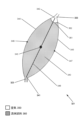
幾つかの実施形態では、アッセイチャンバは両側テーパ状チャンバを含み、その両側テーパ状チャンバは、テーパ状入口、テーパ状出口、及び2つの湾曲境界を含む。テーパ状入口は、流体経路の入口導管の終端部と流体連通している。同様に、テーパ状出口は、空気区画の終端部と流体連通しており、しばしば空気導管の終端部と流体連通している。2つの湾曲境界は、2つの湾曲境界が一緒にアッセイチャンバの体積を囲むように、テーパ状入口からテーパ状出口まで延びている。更に、テーパ状入口とテーパ状出口は、アッセイチャンバ体積の最大寸法だけ離れている。更に、各湾曲境界は中点を含み、2つの湾曲境界が中点からテーパ状入口に向かって、並びに中点からテーパ状出口に向かって湾曲するにつれて、それらの湾曲境界の間の距離が短くなっていく。 In some embodiments, the assay chamber includes a double-sided tapered chamber that includes a tapered inlet, a tapered outlet, and two curved boundaries. The tapered inlet is in fluid communication with the terminal end of the inlet conduit of the fluid path. Similarly, the tapered outlet is in fluid communication with the terminal end of the air compartment, and often with the terminal end of the air conduit. Two curved boundaries extend from the tapered inlet to the tapered outlet such that the two curved boundaries together enclose the volume of the assay chamber. Further, the tapered inlet and tapered outlet are separated by a maximum dimension of the assay chamber volume. Further, each curved boundary includes a midpoint, and as the two curved boundaries curve from the midpoint toward the tapered inlet and from the midpoint toward the tapered outlet, the distance between the curved boundaries decreases. It's becoming.
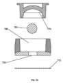
特定の実施形態では、アッセイチャンバは、モノリシック基板に形成された第1の境界表面と、プラグで形成された第2の境界表面とを含む。プラグは本体及びキャップを含む。プラグの本体はある深さでアッセイチャンバのモノリシック基板内に突出しており、プラグの本体がアッセイチャンバのモノリシック基板内に突出する深さを変化させることによって、アッセイチャンバ体積を変化させることが容易に可能である。具体的には、プラグのキャップは、アッセイチャンバの第2の境界表面を形成する。別の実施形態では、アッセイチャンバの第3の境界表面が膜で形成されてよく、第1の境界表面、第2の境界表面、及び第3の境界表面が一緒にアッセイチャンバ体積を囲む。幾つかの実施形態では、プラグキャップは、アッセイチャンバ内で行われるアッセイで使用される1つ以上の乾燥試薬を保持するように構成された内部キャビティを含む。更に、アッセイチャンバ内でのアッセイの作動を容易にする磁気式混合要素がアッセイチャンバ内に置かれてよい。 In certain embodiments, the assay chamber includes a first interface surface formed in a monolithic substrate and a second interface surface formed in a plug. The plug includes a body and a cap. The body of the plug protrudes at a depth into the monolithic substrate of the assay chamber, making it easy to vary the assay chamber volume by varying the depth at which the body of the plug protrudes into the monolithic substrate of the assay chamber. It is possible. Specifically, the cap of the plug forms a second bounding surface of the assay chamber. In another embodiment, the third bounding surface of the assay chamber may be formed of a membrane, and the first bounding surface, the second bounding surface, and the third bounding surface together surround the assay chamber volume. In some embodiments, the plug cap includes an internal cavity configured to hold one or more dry reagents used in an assay performed within the assay chamber. Additionally, a magnetic mixing element may be placed within the assay chamber to facilitate actuation of the assay within the assay chamber.
本開示の装置の特定の態様では、本装置の一部分に1つ以上の膜が接着されてよい。例えば、本装置の少なくとも一部分の表面に第1の膜が接着されてよく、第1の膜は、本装置の1つ以上のチャンバ、区画、又は導管の1つの壁を形成する。後で詳しく論じる特定の実施形態では、本装置の1つ以上の流体経路の一部分を熱で封止することが望ましい場合がある。そこで、そのような実施形態では、融解温度がより高い第2の膜14が第1の膜12に接着されてよい。 In certain aspects of the devices of the present disclosure, one or more membranes may be adhered to a portion of the device. For example, a first membrane may be adhered to a surface of at least a portion of the device, the first membrane forming a wall of one or more chambers, compartments, or conduits of the device. In certain embodiments, discussed in detail below, it may be desirable to thermally seal a portion of one or more fluid paths of the device. Thus, in such embodiments, a second membrane 14 having a higher melting temperature may be adhered to the first membrane 12.
更なる別個の態様では、本開示は、複数の試料チャンバの同時充填を行う方法を提供する。本方法は、上述の実施形態のうちの1つ以上による装置を用意するステップを含む。複数の試料チャンバの同時充填での使用の為に、用意される装置の共通流体源は流体試料を収容し、用意される装置の独立した連続的な流体経路のそれぞれは、気体(例えば、空気等)を収容する。本装置が用意された後、共通流体源中の流体試料に供給圧力が印加され、これによって、流体試料が共通流体源から本装置の各流体経路の試料チャンバへと押し出される。特定の実施形態では、供給圧力は一定圧力で印加される。別の実施形態では、供給圧力は、低い圧力から高い圧力にかけて印加される。特定の態様では、流体試料は、重力に逆らって入口導管を通って複数の試料チャンバまで移動する。このように流体試料を本装置の各流体経路の試料チャンバまで送達することにより、流体経路内の気体が流体経路の空気区画に向かって圧縮される。そしてこれにより、流体経路の空気区画の内圧が上昇する。空気区画の内圧が供給圧力と等しくなった時点で、共通流体源から流体経路への流体試料の流れが停止する。 In a further separate aspect, the present disclosure provides a method for simultaneous filling of multiple sample chambers. The method includes providing an apparatus according to one or more of the embodiments described above. For use in simultaneous filling of multiple sample chambers, a common fluid source of the provided device contains a fluid sample, and each independent continuous fluid path of the provided device contains a gas (e.g., air). etc.). After the device is primed, a supply pressure is applied to the fluid sample in the common fluid source, thereby forcing the fluid sample from the common fluid source into the sample chamber of each fluid path of the device. In certain embodiments, the supply pressure is applied at a constant pressure. In another embodiment, the supply pressure is applied from low pressure to high pressure. In certain embodiments, a fluid sample moves against gravity through an inlet conduit to a plurality of sample chambers. By delivering a fluid sample to the sample chamber of each fluid path of the device in this manner, the gas within the fluid path is compressed toward the air compartment of the fluid path. This in turn increases the internal pressure in the air compartment of the fluid path. Once the internal pressure of the air compartment equals the supply pressure, the flow of fluid sample from the common fluid source to the fluid path is stopped.
本開示の方法の幾つかの実施形態では、用意された装置の少なくとも2つの試料チャンバの体積が異なる。例えば、用意された装置の第1の流体経路の試料チャンバの流体体積は、用意された装置の第2の流体経路の試料チャンバの流体体積より大きくてよい。大まかには、共通流体源から複数の試料チャンバの各試料チャンバに入る流量が試料チャンバの流体体積に比例する。更に、上述のように、空気体積に対する流体体積の比は、用意された装置の各流体経路の間でほぼ同等である。従って、用意された装置の試料チャンバは、第1の流体経路及び第2の流体経路の、サイズの異なる試料チャンバを含み、それらの試料チャンバの充填が同時に行われるように、ほぼ比例する流量で充填される。 In some embodiments of the disclosed method, at least two sample chambers of the provided device have different volumes. For example, the fluid volume of the sample chamber of the first fluid path of the provisioned device may be greater than the fluid volume of the sample chamber of the second fluid path of the provisioned device. Broadly speaking, the flow rate into each sample chamber of the plurality of sample chambers from a common fluid source is proportional to the fluid volume of the sample chamber. Furthermore, as mentioned above, the ratio of fluid volume to air volume is approximately equivalent between each fluid path of a given device. The sample chambers of the prepared device therefore include sample chambers of different sizes in the first fluid path and in the second fluid path, with substantially proportional flow rates so that the filling of the sample chambers occurs simultaneously. Filled.
上述のように、本開示の方法によって用意される装置の特定の実施形態は、1つ以上の試料チャンバを含んでよく、それらの試料チャンバは両側テーパ状チャンバを含む。そのような、用意された装置の1つ以上の試料チャンバが両側テーパ状チャンバを含む実施形態では、両側テーパ状チャンバの2つの湾曲境界によって、流体試料のメニスカスの前面先導部における流体前進速度が低下し、これによって、流体試料がテーパ状出口に達した時点で、流体試料のメニスカスはアッセイチャンバの最大寸法に関してほぼ対称であり、これによって、充填中のアッセイチャンバ内での気泡のトラッピングが最小限に抑えられる。 As mentioned above, certain embodiments of devices prepared by the methods of the present disclosure may include one or more sample chambers, including double-sided tapered chambers. In such embodiments in which one or more of the sample chambers of the provided device includes a double-sided tapered chamber, the two curved boundaries of the double-sided tapered chamber cause the fluid advance velocity at the front leading edge of the meniscus of the fluid sample to increase. and thereby, once the fluid sample reaches the tapered outlet, the meniscus of the fluid sample is approximately symmetrical with respect to the largest dimension of the assay chamber, thereby minimizing trapping of air bubbles within the assay chamber during filling. can be kept to a minimum.
やはり上述のように、特定の態様では、本装置の流体経路を熱で封止することが望ましい場合がある。そのような態様では、本明細書に開示の方法は更に、共通流体源から流体経路への流体試料の流れが停止した時点で複数の流体経路の各流体経路を封止するステップを含む。この封止するステップは熱カシメによって実施されてよい。 Also as mentioned above, in certain embodiments it may be desirable to thermally seal the fluid path of the device. In such aspects, the methods disclosed herein further include sealing each fluid path of the plurality of fluid paths once flow of fluid sample from the common fluid source to the fluid path has ceased. This sealing step may be performed by heat staking.
更に別の態様では、本開示は、上述の装置の様々な実施形態と異なる、乾燥試薬を再水和する装置を提供する。そのような態様では、対象となる装置はアッセイチャンバを含む。アッセイチャンバは、モノリシック基板に形成された第1の境界表面と、プラグで形成された第2の境界表面とを含む。プラグは本体及びキャップを含む。プラグの本体はある深さでアッセイチャンバのモノリシック基板内に突出しており、プラグの本体がアッセイチャンバのモノリシック基板内に突出する深さを変化させることによって、アッセイチャンバ体積を変化させることが容易に可能である。具体的には、プラグのキャップは、アッセイチャンバの第2の境界表面を形成する。アッセイチャンバの第1の境界表面及び第2の境界表面は一緒に、アッセイチャンバの体積を囲む。プラグのキャップに形成される内部キャビティが、アッセイチャンバ内で行われるアッセイで使用される1つ以上の乾燥試薬を保持することが可能である。アッセイチャンバは、アッセイチャンバの体積内に磁気式混合要素を収容する。磁気式混合要素は、アッセイチャンバ体積内で旋回することが可能である。 In yet another aspect, the present disclosure provides an apparatus for rehydrating dried reagents that is different from the various embodiments of the apparatus described above. In such embodiments, the subject device includes an assay chamber. The assay chamber includes a first bounding surface formed in the monolithic substrate and a second bounding surface formed in the plug. The plug includes a body and a cap. The body of the plug protrudes at a depth into the monolithic substrate of the assay chamber, making it easy to vary the assay chamber volume by varying the depth at which the body of the plug protrudes into the monolithic substrate of the assay chamber. It is possible. Specifically, the cap of the plug forms a second bounding surface of the assay chamber. The first bounding surface and the second bounding surface of the assay chamber together surround a volume of the assay chamber. An internal cavity formed in the cap of the plug can hold one or more dry reagents used in an assay performed within the assay chamber. The assay chamber houses a magnetic mixing element within the volume of the assay chamber. The magnetic mixing element is capable of pivoting within the assay chamber volume.
乾燥試薬を再水和する装置の特定の実施形態では、アッセイチャンバは膜の第3の境界表面を含む。そのような実施形態では、第1の境界表面、第2の境界表面、及び第3の境界表面が一緒にアッセイチャンバ体積を囲む。 In certain embodiments of the device for rehydrating dried reagents, the assay chamber includes a third interfacial surface of the membrane. In such embodiments, the first bounding surface, the second bounding surface, and the third bounding surface together surround the assay chamber volume.
更なる別個の態様では、本開示は、乾燥試薬を可溶化する方法を提供する。本方法は、上述の実施形態の1つによる、乾燥試薬を再水和する装置を用意するステップを含む。本方法は更に、アッセイチャンバに流体を充填するステップと、本装置のアッセイチャンバの外側の磁石を回転させることにより、アッセイチャンバ内で磁気式混合要素の旋回を引き起こすステップとを含む。この、アッセイチャンバ内での磁気式混合要素の旋回によって、試薬が流体内で可溶化される。 In a further separate aspect, the present disclosure provides methods of solubilizing dry reagents. The method includes providing an apparatus for rehydrating dried reagents according to one of the embodiments described above. The method further includes filling the assay chamber with a fluid and causing swirling of the magnetic mixing element within the assay chamber by rotating a magnet outside the assay chamber of the device. This swirling of the magnetic mixing element within the assay chamber solubilizes the reagent within the fluid.
概して、一実施形態では、プラグは、底面を有する本体と、本体の中央開口部と、底面上の乾燥試薬とを含み、本体は、赤色スペクトル、青色スペクトル、及び緑色スペクトルのうちの少なくとも1つにおける励起波長及び発光波長に対して透過性を有する材料から形成されている。 Generally, in one embodiment, the plug includes a body having a bottom surface, a central opening in the body, and a dry reagent on the bottom surface, the body having at least one of a red spectrum, a blue spectrum, and a green spectrum. It is made of a material that is transparent to the excitation and emission wavelengths.
この実施形態及び他の実施形態は、以下の特徴のうちの1つ以上を含んでよい。乾燥試薬は、底面のうちの、本体の中央開口部の幅より幅広な部分の上にあってよい。中央開口部の幅が、底面のうちの、乾燥試薬を収容している部分より幅広であってよい。プラグは更に、底面に、乾燥試薬が入るキャビティを含んでよい。プラグは更に、中央開口部の底部とプラグ本体の底部との間のプラグ厚さを含んでよく、キャビティの深さがプラグ厚さの90%未満である。プラグは更に、中央開口部の底部とプラグ本体の底部との間のプラグ厚さを含んでよく、キャビティの深さがプラグ厚さの70%未満である。プラグは更に、中央開口部の底部とプラグ本体の底部との間のプラグ厚さを含んでよく、キャビティの深さがプラグ厚さの50%未満である。プラグは更に、プラグ本体の外側エッジからキャビティの外周部にかけての環形をプラグ底面上に含んでよい。環形はキャビティの外周部を完全に取り囲んでよい。キャビティは更に、底面に外周部を含んでよく、キャビティの開始角度が外周部から、底面に対して測定され、開始角度は60度以下である。キャビティはプラグ本体中央開口部より幅広であってよい。プラグ本体中央開口部はキャビティより幅広であってよい。プラグ本体底面は更に、境界のあるエリアをプラグ本体底面上に含んでよく、乾燥試薬は境界のあるエリアの中にある。プラグ底面上の境界のあるエリアは、プラグ本体底面上のフィーチャによって与えられる。フィーチャは、プラグ底面の上方に持ち上げられているか、プラグ底面に埋め込まれていてよい。フィーチャは湾曲断面又は矩形断面を有してよい。境界のあるエリアの幅が本体中央開口部の幅より大きくてよく、或いは境界のあるエリアの幅が本体中央開口部の幅より小さくてよく、或いは境界のあるエリアの幅が本体中央開口部の幅とほぼ同じであってよい。プラグは研磨仕上げ又は平滑仕上げであることで、励起波長及び発光波長の透過性を促進してよい。プラグは更に、プラグ本体上の、プラグ本体の中央開口部の周囲にフランジを含んでよい。乾燥試薬は、核酸合成試薬、ペプチド合成試薬、ポリマー合成試薬、核酸、ヌクレオチド、核酸塩基、ヌクレオシド、ペプチド、アミノ酸、モノマー、検出試薬、触媒、又はこれらの組み合わせから成る群から選択されてよい。乾燥試薬は、プラグ底面に付着する連続膜であってよい。乾燥試薬は凍結乾燥試薬であってよい。乾燥試薬は、プラグ底面に付着する複数の液滴を含んでよい。 This and other embodiments may include one or more of the following features. The dry reagent may be on a portion of the bottom surface that is wider than the width of the central opening of the body. The width of the central opening may be wider than the portion of the bottom surface containing the dry reagent. The plug may further include a cavity in the bottom surface for containing the dry reagent. The plug may further include a plug thickness between the bottom of the central opening and the bottom of the plug body, the depth of the cavity being less than 90% of the plug thickness. The plug may further include a plug thickness between the bottom of the central opening and the bottom of the plug body, the depth of the cavity being less than 70% of the plug thickness. The plug may further include a plug thickness between the bottom of the central opening and the bottom of the plug body, wherein the depth of the cavity is less than 50% of the plug thickness. The plug may further include an annulus on the bottom of the plug from the outer edge of the plug body to the outer periphery of the cavity. The annulus may completely surround the outer periphery of the cavity. The cavity may further include a perimeter at the bottom surface, and a starting angle of the cavity is measured from the perimeter with respect to the bottom surface, and the starting angle is less than or equal to 60 degrees. The cavity may be wider than the central opening of the plug body. The plug body central opening may be wider than the cavity. The bottom plug body may further include a bounded area on the bottom of the plug body, and the dry reagent is within the bounded area. A bounded area on the bottom of the plug is given by a feature on the bottom of the plug body. The features may be raised above the bottom of the plug or recessed into the bottom of the plug. The features may have curved or rectangular cross sections. The width of the bounded area may be greater than the width of the central body opening, or the width of the bounded area may be less than the width of the central body opening, or the width of the bounded area may be less than the width of the central body opening. It may be approximately the same as the width. The plug may have a polished or smooth finish to facilitate transmission of excitation and emission wavelengths. The plug may further include a flange on the plug body about the central opening of the plug body. The dry reagents may be selected from the group consisting of nucleic acid synthesis reagents, peptide synthesis reagents, polymer synthesis reagents, nucleic acids, nucleotides, nucleobases, nucleosides, peptides, amino acids, monomers, detection reagents, catalysts, or combinations thereof. The dry reagent may be a continuous film that adheres to the bottom of the plug. The dry reagent may be a lyophilized reagent. The dry reagent may include a plurality of droplets that adhere to the bottom of the plug.
概して、一実施形態では、アッセイチャンバがテーパ状入口と、テーパ状出口と、底面を含むプラグと、本体の中央開口部とを含み、本体は、紫外スペクトル、青色スペクトル、緑色スペクトル、及び赤色スペクトルのうちの少なくとも1つにおける励起波長及び発光波長に対して透過性を有する材料から形成されており、更に2つの湾曲境界を含み、2つの湾曲境界とプラグとが一緒にアッセイチャンバの体積を囲むように、各湾曲境界がテーパ状入口からテーパ状出口まで延びており、更に各湾曲境界から延びる肩部を含み、プラグが各肩部と接触することによって、アッセイチャンバの境界が2つの湾曲境界によって与えられ、肩部は湾曲境界のそれぞれとプラグとから延びる。 Generally, in one embodiment, the assay chamber includes a tapered inlet, a tapered outlet, a plug including a bottom surface, and a central opening in the body, the body being configured to have wavelengths in the ultraviolet, blue, green, and red spectra. and further includes two curved boundaries, the two curved boundaries and the plug together enclosing the volume of the assay chamber. such that each curved boundary extends from a tapered inlet to a tapered outlet and further includes a shoulder extending from each curved boundary, and contact of the plug with each shoulder causes the assay chamber to have two curved boundaries. and a shoulder extends from each of the curved boundaries and the plug.
この実施形態及び他の実施形態は、以下の特徴のうちの1つ以上を含んでよい。プラグは、アッセイチャンバ内でプラグ上に乾燥試薬を有してよい。プラグ上のキャビティが肩部のそれぞれの間に位置してよく、乾燥試薬はキャビティ内にある。湾曲境界又は肩部の一部分が、キャビティの外周部に合致する形状になっていてよい。プラグ上の乾燥試薬が肩部のそれぞれの間に位置してよい。プラグ本体の底部の平らな一部分が肩部に接触してよい。アッセイチャンバの体積を調節する為に、肩部のそれぞれの高さが使用されてよい。肩部のそれぞれの高さは100マイクロメートル以上であってよい。肩部のそれぞれの高さは、2つの湾曲境界の、離隔距離が最大になった時点での互いからの距離を超えなくてよい。肩部は、テーパ状入口からテーパ状出口にかけてアッセイチャンバの湾曲境界全体を保持する形状になっていてよい。2つの湾曲境界及び肩部はモノリシック基板に形成されてよい。アッセイは更に、モノリシック基板の表面に接着された膜を含んでよく、この膜はアッセイチャンバの1つの壁を形成する。アッセイチャンバはプラグを有してよい。 This and other embodiments may include one or more of the following features. The plug may have dry reagents on it within the assay chamber. A cavity on the plug may be located between each of the shoulders, and the dry reagent is within the cavity. A portion of the curved boundary or shoulder may be shaped to match the outer periphery of the cavity. A dry reagent on the plug may be located between each of the shoulders. A flat portion of the bottom of the plug body may contact the shoulder. The respective heights of the shoulders may be used to adjust the volume of the assay chamber. The height of each shoulder may be 100 micrometers or more. The height of each shoulder may not exceed the distance of the two curved boundaries from each other at their maximum separation. The shoulder may be shaped to hold the entire curved boundary of the assay chamber from the tapered inlet to the tapered outlet. Two curved boundaries and a shoulder may be formed on a monolithic substrate. The assay may further include a membrane adhered to the surface of the monolithic substrate, which membrane forms one wall of the assay chamber. The assay chamber may have a plug.
概して、一実施形態では、装置が、共通流体経路と、共通流体経路に接続された、複数の独立した連続的な流体経路とを含み、独立した連続的な流体経路のそれぞれはアッセイチャンバ及び空気区画を含む。アッセイチャンバは共通流体経路に接続されており、アッセイチャンバの流体体積の一部が、乾燥試薬をプラグ上に有するそのプラグによって定義されており、空気区画は、空気体積を有していて、アッセイチャンバを介して共通流体経路につながっている。複数の独立した連続的な流体経路の各流体経路は、アッセイチャンバと共通流体源との接続を含まない閉鎖系である。各アッセイチャンバは両側テーパ状チャンバを含み、肩部が各湾曲境界から延びており、プラグが各肩部と接触することによって、アッセイチャンバの境界が2つの湾曲境界によって与えられ、肩部は湾曲境界のそれぞれとプラグとから延びる。両側テーパ状チャンバは、流体経路の入口導管の終端部と流体連通しているテーパ状入口と、空気区画の終端部と流体連通しているテーパ状出口と、2つの湾曲境界であって、この2つの湾曲境界が一緒にアッセイチャンバの体積を囲むように、各湾曲境界がテーパ状入口からテーパ状出口まで延びている、2つの湾曲境界と、を含む。 Generally, in one embodiment, an apparatus includes a common fluid path and a plurality of independent continuous fluid paths connected to the common fluid path, each independent continuous fluid path connecting an assay chamber and an air Contains compartments. The assay chamber is connected to a common fluid path, a portion of the fluid volume of the assay chamber is defined by its plug having a dry reagent on the plug, and an air compartment has an air volume and a portion of the fluid volume of the assay chamber is defined by the plug having a dry reagent on the plug. A common fluid path is connected through the chamber. Each fluid path of the plurality of independent and continuous fluid paths is a closed system that does not include a connection between the assay chamber and a common fluid source. Each assay chamber includes a double-sided tapered chamber, a shoulder extending from each curved boundary, and a plug in contact with each shoulder such that the boundaries of the assay chamber are defined by the two curved boundaries, and the shoulders extend from each curved boundary. extending from each of the boundaries and the plug. The double-sided tapered chamber has a tapered inlet in fluid communication with the terminal end of the inlet conduit of the fluid path and a tapered outlet in fluid communication with the terminal end of the air compartment; two curved boundaries, each curved boundary extending from a tapered inlet to a tapered outlet such that the two curved boundaries together surround the volume of the assay chamber.
この実施形態及び他の実施形態は、以下の特徴のうちの1つ以上を含んでよい。プラグ上のキャビティが肩部のそれぞれの間に位置してよく、乾燥試薬はキャビティ内にある。プラグ上の乾燥試薬が肩部のそれぞれの間に位置してよい。プラグ本体の底部の平らな一部分が肩部に接触してよい。アッセイチャンバの体積を調節する為に、肩部のそれぞれの高さが使用されてよい。肩部のそれぞれの高さは100マイクロメートル以上であってよい。肩部は、テーパ状入口からテーパ状出口にかけてアッセイチャンバの湾曲境界全体を保持する形状になっていてよい。2つの湾曲境界はモノリシック基板に形成されてよい。プラグの本体はある深さでアッセイチャンバのモノリシック基板内に突出してよく、プラグの本体がアッセイチャンバのモノリシック基板内に突出する深さを変化させることによって、アッセイチャンバ体積を変化させることが容易に可能である。湾曲境界又は肩部の一部分が、キャビティの外周部に合致する形状になっていてよい。本装置は更に、本装置の少なくとも一部分の表面に接着された第1の膜を含んでよい。第1の膜は、本装置の1つ以上のチャンバ、区画、又は導管の1つの壁を形成してよい。本装置は更に、第1の膜に接着された第2の膜を含んでよい。第2の膜は第1の膜より融解温度が高くてよい。本装置は更に、第1の膜又は第2の膜を使用して流体経路のそれぞれに形成された熱カシメ領域を含んでよい。熱カシメ領域は、共通流体経路をアッセイチャンバ及び空気チャンバから封鎖してよい。本装置は更に、複数の独立した連続的な流体経路のそれぞれの中に持ち上がったプラットフォームを含んでよく、この持ち上がったプラットフォームはアッセイチャンバの入口と共通流体経路との間に位置する。熱カシメ領域は、持ち上がったプラットフォームの一部分を使用して形成されてよい。本装置はプラグを有してよい。 This and other embodiments may include one or more of the following features. A cavity on the plug may be located between each of the shoulders, and the dry reagent is within the cavity. A dry reagent on the plug may be located between each of the shoulders. A flat portion of the bottom of the plug body may contact the shoulder. The respective heights of the shoulders may be used to adjust the volume of the assay chamber. The height of each shoulder may be 100 micrometers or more. The shoulder may be shaped to hold the entire curved boundary of the assay chamber from the tapered inlet to the tapered outlet. Two curved boundaries may be formed in a monolithic substrate. The body of the plug may protrude at a depth into the monolithic substrate of the assay chamber, and by varying the depth at which the body of the plug protrudes into the monolithic substrate of the assay chamber, the assay chamber volume can be easily varied. It is possible. A portion of the curved boundary or shoulder may be shaped to match the outer periphery of the cavity. The device may further include a first membrane adhered to a surface of at least a portion of the device. The first membrane may form one wall of one or more chambers, compartments, or conduits of the device. The device may further include a second membrane adhered to the first membrane. The second film may have a higher melting temperature than the first film. The device may further include a thermally swaged region formed in each of the fluid paths using the first membrane or the second membrane. A thermally swaged region may seal off a common fluid path from the assay chamber and the air chamber. The apparatus may further include a raised platform within each of the plurality of independent and continuous fluid paths, the raised platform being located between the entrance of the assay chamber and the common fluid path. The thermal staking area may be formed using a portion of the raised platform. The device may have a plug.
概して、一実施形態では、複数の試料チャンバの同時充填を行う方法が、(1)共通流体経路内の流体試料を加圧するステップと、(2)共通流体経路から複数の入口導管に流体試料を導入するステップと、(3)入口導管のそれぞれに沿って入口導管のそれぞれの入口導管終端部に向けて流体試料を流すステップであって、各入口導管は試料チャンバに接続されている、上記ステップと、(4)各試料チャンバのテーパ状入口部分に沿って流体試料を流すステップと、(5)各試料チャンバ内で肩部のペアに隣接する前記流体試料をプラグに沿って流すステップと、(6)流体試料を各試料チャンバのテーパ状出口部分に沿って空気区画終端部に向けて流すステップと、(7)各入口導管及び各試料チャンバに収容されていた気体を、各空気区画終端部と連通している空気チャンバ内へと押し退けるステップと、を含む。 Generally, in one embodiment, a method for simultaneous filling of multiple sample chambers includes (1) pressurizing a fluid sample in a common fluid path; and (2) directing fluid samples from the common fluid path into multiple inlet conduits. (3) flowing a fluid sample along each of the inlet conduits toward a respective inlet conduit termination of the inlet conduits, each inlet conduit being connected to a sample chamber; (4) flowing a fluid sample along a tapered inlet portion of each sample chamber; and (5) flowing the fluid sample along a plug adjacent a pair of shoulders within each sample chamber. (6) flowing the fluid sample along the tapered outlet portion of each sample chamber toward the end of the air compartment; and (7) directing the gas contained in each inlet conduit and each sample chamber to the end of each air compartment. displacing the air into an air chamber in communication with the air chamber.
この実施形態及び他の実施形態は、以下の特徴のうちの1つ以上を含んでよい。流体試料を加圧する上記ステップは一定圧力で実施されてよい。一定圧力は、5、10、20、40、又は60psiのうちの1つであってよい。流体を加圧する上記ステップは更に、流体試料を一連の増加する圧力レベルで加圧することを含んでよい。圧力の各増加レベルは一定の継続時間で印加されてよい。圧力の各増加レベルは一定量ずつ増やされてよい。流体試料を加圧する上記ステップにより、低い圧力レベルから高い圧力レベルにかけての一連の圧力レベルが印加されてよい。使用時に、空気チャンバが試料チャンバの上方にあってよく、その為、流体試料を試料チャンバのテーパ状出口部分に沿って空気区画終端部に向けて流す上記ステップ、並びに各入口導管に収容されていた気体を押し退ける上記ステップは、重力に逆らって実施されてよい。使用時には、前記複数の試料チャンバの方向付けが、複数の試料チャンバのうちの特定の試料チャンバに関連付けられた各空気チャンバが試料チャンバの上方に位置付けられるように行われる。流体試料を本装置の各流体経路の試料チャンバまで流すことにより、流体経路内の気体が流体経路の空気区画に向かって圧縮されてよい。本方法は更に、空気区画のそれぞれの内圧が共通流体経路に印加されている圧力と等しくなった時点で、流体試料を加圧する上記ステップの間に達した圧力を保持するステップを含んでよい。本方法は更に、気体を押し退ける上記ステップの間に各空気区画の内圧を高めるステップと、共通流体経路に印加されている圧力が各空気区画の内圧と等しくなった時点で内圧を高めることを停止するステップと、を含んでよい。本方法は更に、空気区画のそれぞれの内圧が共通流体経路に印加されている圧力と等しくなった時点で、試料を流す上記ステップのそれぞれを停止するステップを含んでよい。複数の試料チャンバのうちの少なくとも2つの試料チャンバの体積が異なってよい。共通流体経路から複数の試料チャンバの各試料チャンバに入る流量が試料チャンバの流体体積に比例してよく、少なくとも2つの異なる流量がある。本方法は更に、複数の試料チャンバの各試料チャンバの同時充填を行うステップを含んでよい。本方法は更に、流体試料をテーパ状入口に沿って流す上記ステップの途中又は後に、流体試料を試料チャンバ内の分岐する2つの湾曲境界に沿って流すステップを含んでよい。本方法は更に、流体試料を肩部ペアに沿って流す上記ステップの後又は途中に、流体試料を試料チャンバ内の収斂する2つの湾曲境界に沿って流すステップを含んでよい。2つの湾曲境界の収斂によって、流体試料のメニスカスの前面先導部における流体前進速度が低下することが可能であり、これによって、流体試料がテーパ状出口に達した時点で、流体試料のメニスカスはアッセイチャンバの最大寸法に関してほぼ対称であり、これによって、充填中のアッセイチャンバ内での気泡のトラッピングが最小限に抑えられる。本方法は更に、各試料チャンバにおいてメニスカスを空気チャンバ終端部に近接して位置させるステップを含んでよい。本方法は更に、流体試料内で形成された1つ以上の気泡を試料チャンバ内の流体試料のメニスカスに近接して位置させる為に、上記ステップのうちの1つ以上を実施することを含んでよい。メニスカスは空気チャンバ終端部に近接することが可能である。本方法は更に、共通流体経路内の流体試料を加圧する上記ステップを実施する間は複数の入口導管のそれぞれを封止するステップを含んでよい。本方法は更に、試料チャンバのテーパ状部分に沿って流体試料を流す上記ステップを停止した時点で、複数の入口導管のそれぞれを封止するステップを含んでよい。本方法は更に、共通流体経路から入口導管のそれぞれに沿って流体試料を流す上記ステップを停止した時点で、複数の入口導管のそれぞれを封止するステップを含んでよい。封止する上記ステップは更に、入口導管の閉鎖された部分を熱カシメするステップを含んでよい。本方法は更に、第1の膜の、入口導管のそれぞれに近接する部分を加熱するステップと、前記第1の膜を溶融して入口導管のそれぞれを封鎖するステップと、を含んでよい。本方法は更に、全ての入口導管を同時に封止するステップを含んでよい。本方法は更に、第1の膜によって入口導管から隔てられている第2の膜を、溶融することなく加熱するステップを含んでよい。本方法は更に、第2の膜を溶融することなく、入口導管の一部分を第1の膜の一部分に融着させるステップを含んでよい。入口導管のそれぞれを封止した後、第1の膜又は第2の膜の一部分が、入口導管のそれぞれに形成された持ち上がったプラットフォームに融着されてよい。 This and other embodiments may include one or more of the following features. The above step of pressurizing the fluid sample may be performed at a constant pressure. The constant pressure may be one of 5, 10, 20, 40, or 60 psi. The step of pressurizing the fluid may further include pressurizing the fluid sample at a series of increasing pressure levels. Each increased level of pressure may be applied for a fixed duration. Each increased level of pressure may be increased by a fixed amount. The above step of pressurizing the fluid sample may apply a range of pressure levels from low to high pressure levels. In use, the air chamber may be above the sample chamber, such that the above step of flowing the fluid sample along the tapered outlet portion of the sample chamber toward the end of the air compartment, as well as being contained in each inlet conduit. The above step of displacing the trapped gas may be performed against gravity. In use, the plurality of sample chambers are oriented such that each air chamber associated with a particular sample chamber of the plurality of sample chambers is positioned above the sample chamber. By flowing a fluid sample to the sample chamber of each fluid path of the device, gas within the fluid path may be compressed toward the air compartment of the fluid path. The method may further include the step of maintaining the pressure reached during the step of pressurizing the fluid sample once the internal pressure of each of the air compartments is equal to the pressure being applied to the common fluid path. The method further includes increasing the internal pressure of each air compartment during said step of displacing the gas, and ceasing to increase the internal pressure once the pressure applied to the common fluid path equals the internal pressure of each air compartment. The method may include the steps of: The method may further include stopping each of the above steps of flowing the sample once the internal pressure of each of the air compartments equals the pressure being applied to the common fluid path. At least two of the plurality of sample chambers may have different volumes. The flow rate into each sample chamber of the plurality of sample chambers from the common fluid path may be proportional to the fluid volume of the sample chamber, and there are at least two different flow rates. The method may further include simultaneously filling each sample chamber of the plurality of sample chambers. The method may further include flowing the fluid sample along two divergent curved boundaries within the sample chamber, during or after the above step of flowing the fluid sample along the tapered inlet. The method may further include flowing the fluid sample along two converging curved boundaries within the sample chamber, after or during the above step of flowing the fluid sample along the shoulder pair. The convergence of the two curved boundaries allows the fluid advance velocity at the front leading edge of the fluid sample meniscus to decrease, such that once the fluid sample reaches the tapered outlet, the fluid sample meniscus remains at the assay It is approximately symmetrical with respect to the largest dimension of the chamber, which minimizes trapping of air bubbles within the assay chamber during filling. The method may further include positioning the meniscus in each sample chamber proximate an air chamber end. The method further includes performing one or more of the above steps to position one or more bubbles formed within the fluid sample proximate a meniscus of the fluid sample within the sample chamber. good. The meniscus can be close to the end of the air chamber. The method may further include sealing each of the plurality of inlet conduits while performing the above step of pressurizing the fluid sample within the common fluid path. The method may further include sealing each of the plurality of inlet conduits upon ceasing the step of flowing the fluid sample along the tapered portion of the sample chamber. The method may further include sealing each of the plurality of inlet conduits upon ceasing the step of flowing the fluid sample along each of the plurality of inlet conduits from the common fluid path. The step of sealing may further include heat staking the closed portion of the inlet conduit. The method may further include heating a portion of the first membrane proximate each of the inlet conduits and melting the first membrane to seal off each of the inlet conduits. The method may further include sealing all inlet conduits simultaneously. The method may further include heating a second membrane separated from the inlet conduit by the first membrane without melting it. The method may further include fusing a portion of the inlet conduit to a portion of the first membrane without melting the second membrane. After sealing each of the inlet conduits, a portion of the first membrane or the second membrane may be fused to a raised platform formed in each of the inlet conduits.
本出願は、添付図面と併せて読むことにより、更に理解される。本発明対象の例示を目的として、図面には本発明対象の例示的実施形態が示されているが、本開示の発明対象は、開示された特定の方法、デバイス、及びシステムに限定されない。更に、図面は必ずしも正しい縮尺では描かれていない。 This application will be further understood when read in conjunction with the accompanying drawings. For illustrative purposes, the drawings depict exemplary embodiments of the subject matter, but the subject matter of the present disclosure is not limited to the particular methods, devices, and systems disclosed. Additionally, the drawings are not necessarily drawn to scale.
本明細書では、流体試料を流体源から複数の試料チャンバまで送達するシステム、デバイス、及び方法を提供する。幾つかの実施形態では、本デバイスは、複数の独立した、連続的な流体経路を含み、各流体経路は、流体源に接続された試料チャンバと、試料チャンバに接続された空気区画とを含む。空気区画の体積に対する試料チャンバの体積の比は、共通流体源を共有する各流体経路の間でほぼ同等である。幾つかの実施形態では、各流体経路の試料チャンバは、両側テーパ状チャンバ、磁気式混合要素、及び/又はプラグを含む。幾つかの実施形態では、本方法は、複数の試料チャンバに流体試料を同時に充填することを含む。幾つかの実施形態では、本方法は、試料チャンバに流体試料を充填することと、各試料チャンバ内に保持された磁気式混合要素を使用して試料チャンバ内の流体試料を混合することと、を含む。 Systems, devices, and methods are provided herein for delivering a fluid sample from a fluid source to multiple sample chambers. In some embodiments, the device includes a plurality of independent, continuous fluid paths, each fluid path including a sample chamber connected to a fluid source and an air compartment connected to the sample chamber. . The ratio of sample chamber volume to air compartment volume is approximately equivalent between each fluid path sharing a common fluid source. In some embodiments, the sample chamber of each fluid path includes a double-sided tapered chamber, a magnetic mixing element, and/or a plug. In some embodiments, the method includes simultaneously filling multiple sample chambers with a fluid sample. In some embodiments, the method includes: filling sample chambers with a fluid sample; mixing the fluid sample in the sample chambers using a magnetic mixing element retained within each sample chamber; including.
本開示の実施形態の詳細説明の前に、本開示が、説明される特定の実施形態に限定されないこと、従って、当然のことながら変更されてよいことを理解されたい。又、本明細書で使用される術語は、特定の実施形態を説明することのみを目的としており、限定を意図するものではないことも理解されたい。本開示の範囲は、添付の特許請求項によってのみ限定される。 Before a detailed description of embodiments of the present disclosure, it is to be understood that this disclosure is not limited to particular embodiments described, as such may, of course, vary. It should also be understood that the terminology used herein is for the purpose of describing particular embodiments only and is not intended to be limiting. The scope of the disclosure is limited only by the appended claims.
ある範囲の値が与えられた場合、その範囲の上限値と下限値の間にある、文脈が明らかに別の意味でない限り、下限値の単位の10分の1までの各介在値、並びにその述べられた範囲にある他の任意の述べられた値又は介在値が、本開示に包含されることを理解されたい。これらのより小さい範囲の上限値及び下限値は、そのより小さい範囲に独立して含まれうるものであり、やはり本開示に包含され、述べられた範囲にある任意の特に排除される限界値になることもある。述べられた範囲が一方又は両方の限界値を含む場合、それらの含まれる限界値の一方又は両方を排除する範囲も又、本開示に包含される。 Given a range of values, each intervening value between the upper and lower limits of the range, up to one-tenth of the unit of the lower limit, unless the context clearly means otherwise, and its It is to be understood that any other stated or intervening values within the stated ranges are encompassed by this disclosure. The upper and lower limits of these smaller ranges, which may be independently included in the smaller range, are also encompassed by this disclosure, as well as any specifically excluded limit in the stated range. It may happen. Where the stated range includes one or both of the limits, ranges excluding one or both of those included limits are also included in the disclosure.
以下は、本発明を実施する為の具体的な実施形態の例である。これらの例は、例示のみを目的としており、本発明の範囲をいかなる形でも限定するものではない。使用される数値(例えば、量、温度等)については正確を期したが、当然のことながら、多少の実験的な誤差や偏差があることは考慮されたい。 The following are examples of specific embodiments for carrying out the invention. These examples are for illustrative purposes only and are not intended to limit the scope of the invention in any way. Efforts have been made to ensure accuracy with numbers used (eg, amounts, temperatures, etc.) but some experimental errors and deviations should, of course, be accounted for.
別段の定義がない限り、本明細書において使用される全ての技術用語及び科学用語は、本開示の実施形態が属する技術分野の当業者によって一般的に理解されている意味と同じ意味を有する。本開示の実施形態の実施又は試験には本明細書に記載の方法及び材料と同等又は等価である任意の方法及び材料を用いてもよいが、以下では代表的な方法及び材料の例を説明する。記載の方法はいずれも、記載されたイベントの順序で、又は論理的に可能な他の任意の順序で実施されてよい。 Unless otherwise defined, all technical and scientific terms used herein have the same meaning as commonly understood by one of ordinary skill in the art to which an embodiment of this disclosure belongs. Although any methods and materials similar or equivalent to those described herein can be used in the practice or testing of embodiments of the disclosure, representative examples of methods and materials are described below. do. Any of the methods described may be performed in the order of events described or in any other order that is logically possible.
なお、本明細書、及び添付の特許請求の範囲において使用される単数形「a」、「an」、及び「the」は、文脈が明らかに別の意味でない限り、複数の指示物を包含する。 As used in this specification and the appended claims, the singular forms "a," "an," and "the" include plural referents unless the context clearly dictates otherwise. .
システム
本開示には、流体試料を流体源から複数の試料チャンバまで送達するシステム、デバイス、及び方法が含まれる。対象の実施形態によるシステムは、流体源と、複数の独立した連続的な流体経路とを含み、各流体経路は、流体源に接続された試料チャンバと、試料チャンバに接続された空気区画とを含む。流体源、試料チャンバ、及び空気区画は、流体試料を流体源から試料チャンバまで送達する為に互いに併用される。
Systems The present disclosure includes systems, devices, and methods for delivering a fluid sample from a fluid source to multiple sample chambers. A system according to a subject embodiment includes a fluid source and a plurality of independent and continuous fluid paths, each fluid path connecting a sample chamber connected to the fluid source and an air compartment connected to the sample chamber. include. The fluid source, sample chamber, and air compartment are used in conjunction with each other to deliver a fluid sample from the fluid source to the sample chamber.
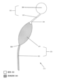
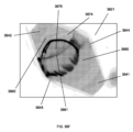
図1は、一実施形態による、流体試料を流体源から複数の試料チャンバまで送達する装置100を示す。本装置は共通流体源101を含み、共通流体源101は複数の独立した連続的な流体経路に接続されている。本装置は、図1では10本の流体経路を含むが、別の実施形態では任意の数の流体経路を含んでよい。例えば、幾つかの実施形態では、本装置は、独立した連続的な流体経路を2本、5本、12本、又は20本含んでよい。
FIG. 1 illustrates an
複数の独立した連続的な流体経路のうちのそれぞれの独立した連続的な流体経路110は、試料チャンバ及び空気区画を含む。幾つかの実施形態では、各試料チャンバは、入口導管122及びアッセイチャンバ121を含む。幾つかの別の実施形態では、各空気区画は、空気導管132及び空気チャンバ131を含む。従って、そのような実施態様では、各流体経路は、入口導管、アッセイチャンバ、空気導管、及び空気チャンバを含む。
Each independent continuous fluid path 110 of the plurality of independent continuous fluid paths includes a sample chamber and an air compartment. In some embodiments, each sample chamber includes an
共通流体源は、流体試料を本装置の各流体経路に供給圧で供給できる入口、チャンバ、導管等である。共通流体源は、複数の流体経路の各流体経路に接続されていて、それらと流体連通している。別の実施態様では、図1に示すように、共通流体源は、各流体経路の入口導管に接続されていて、それらと流体連通している。従って、共通流体源は、流体試料を本装置の各流体経路に、それぞれの入口導管から供給することが可能である。 A common fluid source is an inlet, chamber, conduit, etc. that can supply a fluid sample to each fluid path of the device at a supply pressure. A common fluid source is connected to and in fluid communication with each fluid path of the plurality of fluid paths. In another embodiment, as shown in FIG. 1, a common fluid source is connected to and in fluid communication with the inlet conduits of each fluid path. Thus, a common fluid source is capable of supplying a fluid sample to each fluid path of the device from a respective inlet conduit.
そして各流体経路の入口導管は、流体経路のアッセイチャンバに接続されていて、これと流体連通している。そして流体経路のアッセイチャンバは、流体経路の空気導管に接続されていて、これと流体連通している。図1に示したような特定の実施態様では、空気区画は空気導管を含み、その空気導管は、流体経路の空気チャンバに接続され、これと流体連通している。別の実施態様では、空気区画は、試料チャンバ、又は試料チャンバのアッセイチャンバに直接接続された単一構造で構成されてよい。 The inlet conduit of each fluid pathway is then connected to and in fluid communication with the fluid pathway's assay chamber. The assay chamber of the fluid pathway is then connected to and in fluid communication with the air conduit of the fluid pathway. In certain embodiments, such as that shown in FIG. 1, the air compartment includes an air conduit connected to and in fluid communication with the air chamber of the fluid pathway. In another embodiment, the air compartment may be comprised of a unitary structure that is directly connected to the sample chamber or the assay chamber of the sample chamber.
本明細書では「流体接続」及び「流体連続」という用語は、任意のダクト、チャネル、チューブ、パイプ等の経路が開いているときにその中を液体、気体、又は固体等の物質が無制限に通り抜けられることを意味する。経路が閉じていると、物質は通り抜けがほぼ制限される。典型的には、物質がわずかながら拡散して基板の材料を通り抜けることが、物質や基板材料の組成に応じて起きたり起きなかったりするが、これは流体連通には含まれない。 As used herein, the terms "fluidic connection" and "fluidic continuity" refer to any duct, channel, tube, pipe, etc., through which a substance, such as a liquid, gas, or solid, can flow freely when it is open. It means you can pass through. When the pathway is closed, the passage of matter is largely restricted. Typically, a small amount of diffusion of the substance through the substrate material, which may or may not occur depending on the composition of the substance and the substrate material, is not included in fluid communication.
各流体経路が連続していることにより、共通流体源からの流体試料が流体経路全体にわたって移動することが可能である。具体的には、共通流体源からの流体試料は、各流体経路の入口導管を通ってアッセイチャンバに入り、空気導管を通って空気チャンバに入ることが可能である。しかしながら、幾つかの実施形態では、流体試料を本装置のアッセイチャンバに閉じ込めて、流体試料が空気区画に出ていって失われないようにすることが望ましい場合がある。そのような実施形態については後で詳述する。幾つかの実施形態では、流体試料が重力に逆らって移動して入口導管からアッセイチャンバに入るように、本装置の方向付けが行われる。 The continuity of each fluid path allows fluid samples from a common fluid source to travel throughout the fluid paths. Specifically, a fluid sample from a common fluid source can enter the assay chamber through the inlet conduit of each fluid path and into the air chamber through the air conduit. However, in some embodiments, it may be desirable to confine the fluid sample to the assay chamber of the device so that it does not escape into the air compartment and be lost. Such embodiments are discussed in detail below. In some embodiments, the device is oriented such that the fluid sample moves against gravity and enters the assay chamber through the inlet conduit.
共通流体源と各流体経路の入口導管との接続がない場合、各流体経路は閉鎖系になる。本明細書では「閉鎖系」という用語は、周囲との間で熱交換及びエネルギ交換は可能であるが物質交換は不可能である系を意味する。閉鎖系という用語は、流体経路が形成されている基板の中に水蒸気や酸素のような気体がわずかながら浸透しうることを排除するものではない。言い換えると、流体経路の中にある物質は、共通流体源と流体経路の入口導管との接続を介する場合を除き、流体経路を出入りできない。本明細書に記載の装置を使用する特定の方法では、共通流体源と各流体経路との間の流体接続は、(例えば、熱カシメによって)方法の運用中は封止されている。 Without a connection between the common fluid source and the inlet conduit of each fluid path, each fluid path becomes a closed system. As used herein, the term "closed system" refers to a system that allows heat and energy exchange, but not mass exchange, with its surroundings. The term closed system does not exclude that gases such as water vapor or oxygen may penetrate to a small extent into the substrate in which the fluid path is formed. In other words, substances within the fluid path cannot enter or exit the fluid path except through a connection between a common fluid source and the fluid path's inlet conduit. In certain methods of using the devices described herein, the fluid connections between the common fluid source and each fluid path are sealed (eg, by thermal staking) during operation of the method.
共通流体源と流体経路の入口導管との接続を封鎖することにより、流体経路は、物質が出入りできない完全な閉鎖系になり、その為、変化する変数が全くなく、流体経路の内圧が一定のままになる。そのような、共通流体源と流体経路の入口導管との接続を封鎖する一実施形態について、後で図2E及び2Fに関して詳しく論じる。 By sealing off the connection between the common fluid source and the inlet conduit of the fluid path, the fluid path becomes a completely closed system from which no substances can enter or exit, so that there are no variables that change and the internal pressure of the fluid path remains constant. Leave it alone. One such embodiment of sealing the connection between a common fluid source and a fluid pathway inlet conduit is discussed in detail below with respect to FIGS. 2E and 2F.
上述のように、各流体経路は試料チャンバ及び空気区画を含む。そして、各試料チャンバは入口導管及びアッセイチャンバを含み、各空気区画は空気導管及び空気チャンバを含む。 As mentioned above, each fluid path includes a sample chamber and an air compartment. And each sample chamber includes an inlet conduit and an assay chamber, and each air compartment includes an air conduit and an air chamber.
入口導管は、流体試料を共通流体源から流体経路のアッセイチャンバまで輸送するように構成されている。アッセイチャンバはアッセイを収容するように構成されている。幾つかの実施形態では、アッセイチャンバは、アッセイを促進する機能を含んでよい。例えば、後で図3Bに関して詳しく論じる幾つかの実施形態では、各アッセイチャンバは、アッセイチャンバへの流体試料の送達時の気泡の形成を最小限に抑えるように構成されている。この機能はアッセイ作動時に有利である。それは、幾つかの実施形態では、気泡がチャンバの充填を妨げたり、他の形でアッセイの結果に干渉したりする為である。更に、後で図4~7に関して詳しく論じる幾つかの実施形態では、各アッセイチャンバは、プラグを含むか、且つ/又は、アッセイ作動を促進する乾燥試薬及び/又は磁気式混合要素を含むように構成されている。 The inlet conduit is configured to transport the fluid sample from the common fluid source to the assay chamber of the fluid pathway. The assay chamber is configured to house an assay. In some embodiments, the assay chamber may include functionality to facilitate an assay. For example, in some embodiments discussed in detail with respect to FIG. 3B below, each assay chamber is configured to minimize the formation of air bubbles during delivery of a fluid sample to the assay chamber. This feature is advantageous during assay operation. This is because, in some embodiments, air bubbles may prevent filling of the chamber or otherwise interfere with the results of the assay. Additionally, in some embodiments discussed in detail with respect to FIGS. 4-7 below, each assay chamber includes a plug and/or includes dry reagents and/or magnetic mixing elements to facilitate assay operation. It is configured.
試料チャンバは空気区画に流体接続されている。入口導管及びアッセイチャンバを含む実施形態では、アッセイチャンバは流体経路の空気区画に接続されている。上述のように、空気区画は空気導管及び空気チャンバを含んでよい。空気導管は、アッセイチャンバを流体経路の空気チャンバにつないでいる。 The sample chamber is fluidly connected to the air compartment. In embodiments that include an inlet conduit and an assay chamber, the assay chamber is connected to the air compartment of the fluid path. As mentioned above, the air compartment may include an air conduit and an air chamber. An air conduit connects the assay chamber to the air chamber of the fluid path.
一装置の各アッセイチャンバが上述のようにアッセイを収容するように構成されている実施形態では、各アッセイチャンバに正確な量の流体試料が充填されるように、且つ、本装置の全てのアッセイチャンバにわたって流体試料の組成が均一になるように、アッセイチャンバに入る流体試料の流量を制御することが有利であろう。これにより、幾つかの実施形態では、アッセイチャンバ内で行われうるアッセイを標準化することが可能になる。従って、各流体経路の空気区画は、空気区画の内圧に応じて、流体経路のアッセイチャンバに入る流体試料の流量を制御するように構成されている。空気区画の構成及び機能については後で詳しく論じる。 In embodiments where each assay chamber of a device is configured to house an assay as described above, each assay chamber is filled with a precise amount of fluid sample, and all assays of the device are It may be advantageous to control the flow rate of the fluid sample entering the assay chamber so that the composition of the fluid sample is uniform across the chamber. This, in some embodiments, allows for standardization of assays that may be performed within the assay chamber. Accordingly, the air compartment of each fluid pathway is configured to control the flow rate of fluid sample into the assay chamber of the fluid pathway in response to the internal pressure of the air compartment. The configuration and function of the air compartment will be discussed in detail later.
各流体経路の試料チャンバ及び空気区画はいずれも、ある体積を有する。試料チャンバの体積を以下では「流体体積」と呼ぶ。流体経路の流体体積は、流体経路の入口導管の体積とアッセイチャンバの体積とを含む。同様に、空気区画の体積を以下では「空気体積」と呼ぶ。流体経路の空気体積は、流体経路の空気導管の体積と空気チャンバの体積とを含む。各試料チャンバの同時充填を達成する為に(特に、複数の流体経路のそれぞれの間で試料チャンバの体積が異なる場合)、共通流体源を共有する各流体経路の間で空気体積に対する流体体積の比は同じである。 Both the sample chamber and air compartment of each fluid path have a certain volume. The volume of the sample chamber will be referred to below as the "fluid volume". The fluid volume of the fluid pathway includes the volume of the inlet conduit of the fluid pathway and the volume of the assay chamber. Similarly, the volume of the air compartment is referred to below as "air volume". The air volume of the fluid path includes the volume of the air conduit and the volume of the air chamber of the fluid path. In order to achieve simultaneous filling of each sample chamber (especially when the sample chamber volumes differ between each of the multiple fluid paths), the fluid volume relative to the air volume between each fluid path that shares a common fluid source must be The ratio is the same.
流体試料が共通流体源から一装置の各流体経路に導入されるまでは、流体経路は、例えば空気等の気体を初期空気圧で含む。本開示全体を通して、空気は、大気気体の混合物、又は本装置において実施されるアッセイに適合する他の任意の気体混合物又は純粋気体を包含するものと解釈されたい。更に、当業者であれば理解されるように、本明細書に記載のデバイス及び方法の流体経路においては、空気の代わりに任意の気体が使用されてよい。例えば、幾つかの実施形態では、空気は別の気体に置き換えられてよく、例えば、不活性気体(例えば、窒素又はアルゴン等)に置き換えられてよい。 Until a fluid sample is introduced into each fluid path of a device from a common fluid source, the fluid paths contain a gas, such as air, at an initial pneumatic pressure. Throughout this disclosure, air is to be construed to include atmospheric gas mixtures or any other gas mixture or pure gas compatible with the assays performed in the present device. Additionally, as will be understood by those skilled in the art, any gas may be used in place of air in the fluid path of the devices and methods described herein. For example, in some embodiments, air may be replaced with another gas, such as an inert gas (eg, nitrogen or argon, etc.).
流体経路内の空気の初期圧力は、流体経路の内圧をある程度決定する。流体試料が共通流体源から流体経路に導入されると、各流体経路内の空気は、流体経路内を前進する流体試料によって押し退けられる。具体的には、前進する流体試料は、流体経路の入口導管から各流体経路に入って、流体経路内の空気を空気チャンバの方向に押し退ける。この押し退けの結果として、流体経路内の空気が占有する体積は減少する。この、空気が占有する体積の減少の結果として、空気の圧力、即ち流体経路の内圧は上昇する。具体的には、内圧は、空気が占有する体積の減少に比例して上昇する。 The initial pressure of the air within the fluid path determines, to some extent, the internal pressure of the fluid path. When fluid samples are introduced into the fluid paths from a common fluid source, air within each fluid path is displaced by the fluid sample advancing within the fluid paths. Specifically, an advancing fluid sample enters each fluid path from the fluid path's inlet conduit and displaces air within the fluid path toward the air chamber. As a result of this displacement, the volume occupied by the air within the fluid path is reduced. As a result of this reduction in the volume occupied by the air, the pressure of the air, and thus the internal pressure of the fluid path, increases. Specifically, the internal pressure increases in proportion to the decrease in volume occupied by air.
流体経路内で供給圧力と内圧が釣り合うように、流体経路内の流体試料の流量が決定される。具体的には、流体経路の内圧が、流体試料が流体経路に供給される際の圧力より低いと、流体試料は流体経路内を前進し続け、流体経路内にある空気を押し退け続け、それによって内圧が上昇する。これに対し、内圧の値が流体試料の供給圧力の値に近いほど、流体経路内で空気から流体試料にかかる圧力が高くなり、流体経路内で流体試料の流量が内圧によって減じられる。流体経路の内圧が流体試料の供給圧力と等しくなった時点で、流体経路への流体試料の流入が止まる。従って、流体経路内の、空気が含まれる体積を制御し、それによって、流体経路の内圧を制御することにより、流体経路内の流体試料の流量を制御することが可能である。 A flow rate of the fluid sample within the fluid path is determined such that the supply pressure and internal pressure are balanced within the fluid path. Specifically, if the internal pressure of the fluid path is lower than the pressure at which the fluid sample is supplied to the fluid path, the fluid sample will continue to advance within the fluid path and displace air that is within the fluid path, thereby Internal pressure increases. In contrast, the closer the value of the internal pressure is to the value of the supply pressure of the fluid sample, the higher the pressure exerted on the fluid sample from the air within the fluid path, and the more the flow rate of the fluid sample within the fluid path is reduced by the internal pressure. When the internal pressure of the fluid path becomes equal to the supply pressure of the fluid sample, the flow of the fluid sample into the fluid path is stopped. Thus, by controlling the air-containing volume within the fluid pathway, and thereby controlling the internal pressure of the fluid pathway, it is possible to control the flow rate of the fluid sample within the fluid pathway.
様々な状況において、流体経路内の流体試料の流量を制御することが望ましい場合がある。特に、特定の実施形態では、流体試料が流体経路の試料チャンバに閉じ込められ、流体経路の空気区画に流入しないように、流体経路内の流体試料の流量を制御することが望ましい場合がある。言い換えると、試料チャンバ(そして幾つかの実施形態では特にアッセイチャンバ)に流体試料がほぼ充填されるように、流体経路内の流体試料の流量を制御することが望ましい場合がある。本明細書では「ほぼ充填」又は「ほぼ一杯」という語句は、試料チャンバの流体体積の少なくとも90%に流体試料が収容されていて、空気区画の空気体積のせいぜい10%に流体試料が収容されていることを意味する。特に流体試料の充填が空気区画の空気体積の10%以下であれば、本装置の動作が乱れることはない。 In various situations, it may be desirable to control the flow rate of a fluid sample within a fluid pathway. In particular, in certain embodiments, it may be desirable to control the flow rate of a fluid sample within a fluid pathway such that the fluid sample is confined to a sample chamber of the fluid pathway and does not flow into an air compartment of the fluid pathway. In other words, it may be desirable to control the flow rate of fluid sample within the fluid pathway such that the sample chamber (and in some embodiments, particularly the assay chamber) is substantially filled with fluid sample. As used herein, the phrase "substantially full" or "substantially full" means that at least 90% of the fluid volume of the sample chamber contains fluid sample and no more than 10% of the air volume of the air compartment contains fluid sample. means that In particular, if the fluid sample filling is less than 10% of the air volume of the air compartment, the operation of the device will not be disturbed.
流体経路の試料チャンバをほぼ充填する為には、試料チャンバに流体試料がほぼ充填されるときに、流体試料が試料チャンバに供給される際の圧力が流体経路の内圧に等しくなければならない。更に、試料チャンバがほぼ充填されているときは流体試料が流体経路の試料チャンバに閉じ込められている為、流体経路内にある空気は、流体経路の空気区画内に圧縮されている。従って、流体経路の試料チャンバをほぼ充填する為には、試料チャンバに流体試料がほぼ充填されるときに、流体試料が試料チャンバに供給される際の圧力が流体経路の空気区画の内圧に等しくなければならない。 In order to substantially fill the sample chamber of the fluid path, the pressure at which the fluid sample is delivered to the sample chamber must be equal to the internal pressure of the fluid path when the sample chamber is substantially filled with the fluid sample. Furthermore, because the fluid sample is confined to the sample chamber of the fluid path when the sample chamber is substantially full, air within the fluid path is compressed into the air compartment of the fluid path. Therefore, in order to approximately fill the sample chamber of the fluid path, the pressure at which the fluid sample is supplied to the sample chamber must be equal to the internal pressure of the air compartment of the fluid path when the sample chamber is approximately filled with the fluid sample. There must be.
上述のように、内圧は、ある程度は試料チャンバから押し退けられた空気の体積に依存し、ある程度は押し退けられた空気を閉じ込めている体積に依存する。従って、流体経路の試料チャンバに流体試料がほぼ充填されると、押し退けられた空気は空気区画に閉じ込められ、内圧は、空気区画の空気体積と、試料チャンバの流体体積とに依存する。 As mentioned above, the internal pressure depends in part on the volume of air displaced from the sample chamber and in part on the volume confining the displaced air. Thus, when the sample chamber of the fluid path is substantially filled with the fluid sample, the displaced air is trapped in the air compartment, and the internal pressure depends on the air volume of the air compartment and the fluid volume of the sample chamber.
従って、試料チャンバに流体試料がほぼ充填されたときに内圧と流体試料の供給圧力とを釣り合わせる為に、流体経路の流体体積は、試料チャンバの流体体積と供給圧力とを考慮して意図的に選択されてよい。更に、流体経路の初期内圧と流体試料の供給圧力も、空気体積の内圧と流体試料の供給圧力とを同等にする要因である為、流体経路の周囲内圧と流体試料の供給圧力も、試料チャンバに流体試料がほぼ充填されたときに流体試料の供給圧力と空気区画の内圧が等しくなるように意図的に選択されてよい。このように内圧と供給圧力が同等になると、試料チャンバがほぼ充填された時点で、流体経路に収容された流体試料にかかる力が正味ゼロになり、これによって、流体経路への流体試料の流入が止まる。 Therefore, in order to balance the internal pressure and the supply pressure of the fluid sample when the sample chamber is almost filled with the fluid sample, the fluid volume of the fluid path is intentionally set in consideration of the fluid volume of the sample chamber and the supply pressure. may be selected. Furthermore, since the initial internal pressure of the fluid path and the supply pressure of the fluid sample are also factors that equalize the internal pressure of the air volume and the supply pressure of the fluid sample, the ambient internal pressure of the fluid path and the supply pressure of the fluid sample also The supply pressure of the fluid sample and the internal pressure of the air compartment may be intentionally selected to be equal when the chamber is approximately filled with the fluid sample. This equalization of the internal and supply pressures results in a net zero force on the fluid sample contained in the fluid path when the sample chamber is nearly filled, thereby reducing the flow of the fluid sample into the fluid path. stops.
別の実施形態では、本装置の複数の流体経路内の流体試料の流量を、各流体経路の試料チャンバが同時に充填されるように制御することが望ましい場合がある。しかしながら、上述のように、幾つかの実施形態では、本装置の各流体経路の流体体積は異なってよい。このように各流体体積が異なると、流体試料が各流体経路に同時に流入した場合に、各試料チャンバの充填は同時ではなくなる。もっと正確に言えば、流体体積が異なる複数の流体経路に流体試料が同じ流量で流入すると、流体体積が小さい流体経路は、流体体積が大きい流体経路より先に流体試料が充填される。 In another embodiment, it may be desirable to control the flow rate of fluid sample within multiple fluid paths of the device such that the sample chambers of each fluid path are filled simultaneously. However, as mentioned above, in some embodiments, the fluid volume of each fluid path of the device may be different. This different fluid volume causes the filling of each sample chamber to be non-simultaneous if a fluid sample enters each fluid path at the same time. More precisely, when a fluid sample flows into multiple fluid paths having different fluid volumes at the same flow rate, the fluid path with a smaller fluid volume is filled with the fluid sample before the fluid path with a larger fluid volume.
各流体経路の試料チャンバがその流体体積に関係なく同時に充填されるようにする為に、各流体経路は、各流体経路に流入する流体試料の流量が流体経路の流体体積に比例するように構成されてよい。例えば、第1の流体経路の流体体積が第2の流体経路の流体体積の2倍であれば、第1の流体経路に流入する流体試料の流量が、第2の流体経路に流入する流体試料の流量の2倍であるように構成される。このようにすると、第1の流体経路の試料チャンバと第2の流体経路の試料チャンバは、充填が同時に行われる。 To ensure that the sample chambers of each fluid path are filled simultaneously regardless of their fluid volume, each fluid path is configured such that the flow rate of fluid sample entering each fluid path is proportional to the fluid volume of the fluid path. It's okay to be. For example, if the fluid volume of the first fluid path is twice the fluid volume of the second fluid path, the flow rate of the fluid sample entering the first fluid path will be greater than the flow rate of the fluid sample entering the second fluid path. is configured so that the flow rate is twice that of . In this way, the sample chambers of the first fluid path and the sample chambers of the second fluid path are filled simultaneously.
上述のように、流体試料が共通流体源から流体経路に流入する際の流量は、流体経路の内圧と供給圧力とに依存する。具体的には、内圧の値が供給圧力の値に近いほど、流体経路内で流体試料の流量が内圧によって減じられる。更に、上述のように、収容されている空気の内圧は、空気が収容されている体積にある程度依存する。具体的には、流体経路の、体積が小さい部分に押し退けられた空気は、同体積の空気が最初に流体経路の、体積が大きい部分に押し退けられた場合より、圧力の増加が大きい。 As mentioned above, the flow rate at which the fluid sample enters the fluid path from the common fluid source is dependent on the internal pressure of the fluid path and the supply pressure. Specifically, the closer the value of the internal pressure is to the value of the supply pressure, the more the flow rate of the fluid sample within the fluid path is reduced by the internal pressure. Furthermore, as mentioned above, the internal pressure of the contained air depends to some extent on the volume in which the air is contained. Specifically, air displaced into a smaller volume portion of the fluid path experiences a greater increase in pressure than if the same volume of air were initially displaced into a larger volume portion of the fluid path.
従って、各流体経路に流入する流体試料の流量が流体経路の流体体積に比例するように流体経路を構成する為に、各流体経路は、空気が収容される体積が流体経路の流体体積に比例するように構成されてよい。流体経路の試料チャンバが流体経路のうちの、流体試料が充填される部分である実施形態では、空気が収容される体積は、流体経路の空気体積である。従って、そのような実施形態では、流体経路の内圧と流体経路の流体体積とを反比例させる為に、各流体経路は、流体経路の空気体積が流体経路の流体体積に比例するように構成されてよい。 Therefore, in order to configure the fluid paths such that the flow rate of the fluid sample flowing into each fluid path is proportional to the fluid volume of the fluid path, each fluid path has a volume that accommodates air that is proportional to the fluid volume of the fluid path. may be configured to do so. In embodiments where the sample chamber of the fluid pathway is the portion of the fluid pathway that is filled with a fluid sample, the volume that contains air is the air volume of the fluid pathway. Accordingly, in such embodiments, each fluid pathway is configured such that the air volume in the fluid pathway is proportional to the fluid volume in the fluid pathway to make the internal pressure in the fluid pathway inversely proportional to the fluid volume in the fluid pathway. good.
更に、一装置の各流体経路の試料チャンバの同時充填を達成する為に、この、流体経路の流体体積と流体経路の空気体積との比例関係は、本装置の全ての流体経路の間で同じでなければならない。具体的には、流体経路の空気体積に対する流体体積の比が、本装置の各流体経路の間でほぼ同等でなければならない。なお、本明細書では「ほぼ同等」は、空気体積に対する流体体積の比がせいぜい±10%しか違わないことを意味する。 Furthermore, in order to achieve simultaneous filling of the sample chamber in each fluid path of a device, this proportional relationship between the fluid volume of a fluid path and the air volume of a fluid path is the same between all fluid paths of the device. Must. Specifically, the ratio of fluid volume to air volume of the fluid paths should be approximately equal between each fluid path of the device. Note that in this specification, "substantially equivalent" means that the ratio of fluid volume to air volume differs by at most ±10%.
特定の実施形態では、入口導管及び空気導管の体積は、それぞれ、アッセイチャンバ及び空気チャンバの体積に対して無視できる。具体的には、本明細書では「無視できる」は、流体経路のうちの入口導管の体積が流体経路のうちのアッセイチャンバの体積のせいぜい10%であり、同様に、流体経路のうちの空気導管の体積が流体経路のうちの空気チャンバの体積のせいぜい10%であることを意味する。従って、そのような実施形態では、試料チャンバの流体体積は、大部分がアッセイチャンバの体積で占められ、わずかな部分が入口導管の体積で占められる。同様に、そのような実施形態では、空気区画の空気体積は、大部分が空気チャンバの体積で占められ、わずかな部分が空気導管の体積で占められる。 In certain embodiments, the volumes of the inlet conduit and air conduit are negligible relative to the volumes of the assay chamber and air chamber, respectively. Specifically, "negligible" as used herein means that the volume of the inlet conduit in the fluid path is at most 10% of the volume of the assay chamber in the fluid path; This means that the volume of the conduit is at most 10% of the volume of the air chamber in the fluid path. Accordingly, in such embodiments, the fluid volume of the sample chamber is dominated by the volume of the assay chamber and a small portion by the volume of the inlet conduit. Similarly, in such embodiments, the air volume of the air compartment is mostly occupied by the volume of the air chamber and only a small part by the volume of the air conduit.
幾つかの実施形態では、一装置の1つ以上の流体経路の流体体積は異なってよい。例えば、本装置の第1の流体経路の流体体積は、本装置の第2の流体経路の流体体積より大きくてよい。この、本装置の流体経路間の流体体積の差は、アッセイチャンバ間の体積差、及び/又は流体経路の入口導管間の体積差の結果であってよい。 In some embodiments, the fluid volume of one or more fluid paths of a device may be different. For example, the fluid volume of the first fluid path of the device may be greater than the fluid volume of the second fluid path of the device. This fluid volume difference between the fluid paths of the device may be the result of a volume difference between the assay chambers and/or a volume difference between the inlet conduits of the fluid path.
一装置の1つ以上の流体経路の流体体積が異なる実施形態では、本装置の1つ以上の流体経路の空気体積も異なることになる。その理由については後で詳しく論じる。本装置の流体経路間の空気体積の差は、空気チャンバ間の体積差、及び/又は流体経路の空気導管間の体積差の結果であってよい。 In embodiments where the fluid volumes of one or more fluid paths of a device are different, the air volumes of one or more fluid paths of the device will also be different. The reason for this will be discussed in detail later. Air volume differences between fluid paths of the device may be the result of volume differences between air chambers and/or volume differences between air conduits of the fluid path.
流体経路の入口導管及び空気導管の体積がアッセイチャンバ及び空気チャンバの体積に対して無視できる実施形態では、各流体経路の試料チャンバの同時充填を可能にする為に、流体経路の空気チャンバに対するアッセイチャンバの体積比が、各流体経路の間でほぼ同等であってよい。 In embodiments where the volume of the inlet conduit and air conduit of the fluid path is negligible relative to the volume of the assay chamber and air chamber, the assay for the air chamber of the fluid path can be used to allow simultaneous filling of the sample chamber of each fluid path. The volume ratio of the chambers may be approximately equal between each fluid path.
方法
図2A~2Fは、一実施形態による、共通流体源からの流体試料を各試料チャンバに同時充填する過程における複数の連続した時点での図1の装置を示す。幾つかの実施形態では、本装置は、試料チャンバの充填中は、流体試料が重力に逆らって試料チャンバに移動するように方向付けられる。図1に関して上述したように、本装置の各流体経路の流体体積は異なってよい。従って、本装置の各流体経路の試料チャンバの同時充填を可能にする為に、空気体積に対する流体体積の比が本装置の各流体経路の間でほぼ同等である。
Methods FIGS. 2A-2F illustrate the apparatus of FIG. 1 at multiple successive points in time during the simultaneous filling of each sample chamber with a fluid sample from a common fluid source, according to one embodiment. In some embodiments, the apparatus is oriented such that the fluid sample moves against gravity into the sample chamber during filling of the sample chamber. As discussed above with respect to FIG. 1, the fluid volume of each fluid path of the device may be different. Thus, the ratio of fluid volume to air volume is approximately equal between each fluid path of the device to allow simultaneous filling of the sample chamber of each fluid path of the device.
図2A~2Fの左下隅にある凡例に示すように、空気は、流体経路内で白いスペースで表されている。対照的に、流体試料は、共通流体源内及び流体経路内で黒いスペースで表されている。 Air is represented by white space within the fluid path, as shown in the legend in the lower left corner of FIGS. 2A-2F. In contrast, fluid samples are represented by black spaces within the common fluid source and within the fluid path.
図2Aは、時点Aにおける装置200を示す。時点Aでは、流体経路は空気250が充填されている。時点Aにおいて流体経路に収容されている空気は初期空気圧を有しており、これは流体経路の内圧に少なくともある程度寄与している。時点Aでは、共通流体源201は流体試料260を流体経路に、流体経路の内圧より高い供給圧力で供給している。流体試料の供給圧力が流体経路の内圧より高い為、流体試料は共通流体源から各流体経路の入口導管222に向かって前進している。流体試料が本装置内を前進するにつれて、流体経路に収容されている空気は、流体試料によって本装置の空気チャンバに向かって押し退けられる。このように空気が押し退けられて体積が小さくなると、空気の圧力、従って内圧が上昇する。内圧が上昇するにつれて、前進する流体試料にかかる空気の圧力が大きくなって、流体試料の流量が減じられる。
FIG. 2A shows
図2Bは、時点Aに続く時点Bにおける装置200を示す。時点Bでは、共通流体源201は流体試料260を供給圧力で流体経路に供給し続けている。
FIG. 2B shows the
幾つかの実施形態では、各流体経路の試料チャンバの充填の間ずっと、流体試料の供給圧力は一定圧力で印加される。言い換えると、ある時点での供給圧力は、他の全ての時点での供給圧力と同等である。 In some embodiments, the fluid sample supply pressure is applied at a constant pressure throughout the filling of the sample chamber of each fluid path. In other words, the supply pressure at one point in time is equivalent to the supply pressure at all other times.
別の実施形態では、供給圧力は、時間とともに低圧から高圧へと上昇するように傾斜を付けて印加される。言い換えると、第1の時点での供給圧力は、第1の時点に続く第2の時点での供給圧力より高い。そのような、供給圧力が傾斜を付けて印加される実施形態では、供給圧力は、時間とともに低圧から高圧へと直線的に上昇することが可能である。別の実施形態では、供給圧力に傾斜を付けることは、放物線軌道をたどって行われてよい。別の実施形態では、供給圧力に傾斜を付けることは、任意の別の軌道をたどって行われてよい。供給圧力が傾斜を付けて印加される実施形態では、この、供給圧力に傾斜を付けることにより、充填中に試料チャンバ内に形成されている可能性がある気泡を取り除くことが可能であり、これは、供給圧力が上昇していくと、気泡が圧縮されて、試料チャンバ内のそれらの場所から外れ、解放されて空気区画に入っていくことが可能になる為である。流体試料が重力に逆らって試料チャンバに入っていく特定の実施形態では、この、本装置の方向付けは、外れた気泡が試料チャンバの最上部に移動して空気区画に入ることを支援する。 In another embodiment, the supply pressure is applied in a ramp increasing from low pressure to high pressure over time. In other words, the supply pressure at the first time point is higher than the supply pressure at the second time point following the first time point. In such embodiments where the supply pressure is applied in a ramp, the supply pressure can increase linearly over time from a lower pressure to a higher pressure. In another embodiment, ramping the supply pressure may follow a parabolic trajectory. In other embodiments, ramping the supply pressure may follow any other trajectory. In embodiments where the supply pressure is applied with a ramp, this ramping of the supply pressure can eliminate any air bubbles that may have formed in the sample chamber during filling, and This is because as the supply pressure increases, air bubbles become compressed and dislodged from their location within the sample chamber, allowing them to be released and enter the air compartment. In certain embodiments where the fluid sample enters the sample chamber against gravity, this orientation of the device assists the dislodged air bubbles to move to the top of the sample chamber and into the air compartment.
図2Bに戻ると、時点Bでは、供給圧力は引き続き流体経路の内圧より高い。流体試料の供給圧力が引き続き流体経路の内圧より高い為、流体試料は、各流体経路内を流体経路の空気チャンバ231に向かって前進し続けている。具体的には、図2Bに示すように、流体試料は、各流体経路の少なくとも入口導管222内まで前進してきている。更に、流体試料は、流体経路の一部分であるアッセイチャンバ221内まで前進してきている。従って、空気は流体経路内でトラップされる。共通流体源から流体経路に供給された流体試料の体積が増えるにつれて、そしてそれに応じて、流体試料が流体経路内を空気チャンバに向かって前進するにつれて、各流体経路に収容されている空気は流体経路内で押し退けられて体積が小さくなる。それに応じて、流体経路の内圧は上昇する。このように各流体経路の内圧が上昇した結果として、流体経路内を前進する流体試料にかかる空気の圧力が上昇し、これによって、流体経路内の流体試料の流量が低下する。
Returning to FIG. 2B, at time B, the supply pressure continues to be higher than the internal pressure of the fluid path. Because the supply pressure of the fluid sample continues to be higher than the internal pressure of the fluid path, the fluid sample continues to advance within each fluid path toward the
しかしながら、各流体経路内の内圧の上昇は、本装置の全ての流体経路にわたって均一というわけではない。もっと正確に言えば、流体経路の内圧は、押し退けられた空気の体積に依存する。具体的には、流体が各チャネル内を移動するにつれて、流体の上流の空気は圧縮される。圧縮された気体は、前進する流体流に抵抗する背圧を発生させる。この背圧は、理想気体の法則に従って、元の体積に対する収容されている体積の比に反比例する。例えば、大きな空気体積につながっているチャネルにある流体は、小さな空気体積につながっている同じ長さのチャネルにある流体より高い背圧を受ける。 However, the increase in internal pressure within each fluid path is not uniform across all fluid paths of the device. More precisely, the internal pressure of the fluid path depends on the volume of air displaced. Specifically, as the fluid moves through each channel, the air upstream of the fluid is compressed. The compressed gas creates a back pressure that resists the forward fluid flow. This backpressure is inversely proportional to the ratio of contained volume to original volume, according to the ideal gas law. For example, fluid in a channel leading to a large air volume experiences a higher backpressure than fluid in a channel of the same length leading to a small air volume.
そして、流体の速度は、チャネルに印加されている圧力と、空気体積及び上流チャネルにある圧縮された気体からの背圧との差に比例する。従って、空気体積が大きいチャネルにある流体は、サイズが同じで空気体積が小さいチャネルにある流体より高速で移動する。 The velocity of the fluid is then proportional to the difference between the pressure being applied to the channel and the air volume and back pressure from the compressed gas in the upstream channel. Therefore, fluid in a channel with a large air volume moves faster than fluid in a channel of the same size with a smaller air volume.
更に、上流の気体の体積が更に圧縮されるにつれ、背圧は比例して上昇する。流体の速度は圧力差に比例する為、チャネルが充填されるにつれて徐々に遅くなる。流体に印加された圧力と、圧縮された空気体積からの背圧とが等しくなった時点で、流体流は止まる。 Furthermore, as the upstream gas volume is further compressed, the backpressure increases proportionately. The velocity of the fluid is proportional to the pressure difference, so it gradually slows down as the channel fills. Fluid flow ceases when the pressure applied to the fluid equals the back pressure from the compressed air volume.
図1に関して上述したように、各流体経路の試料チャンバの同時充填を可能にする為に、本装置の幾つかの実施形態では、各流体経路は、流体経路の空気体積が流体経路の流体体積に比例するように構成されている。例えば、流体体積が比較的大きい流体経路は、空気体積も比較的大きい。従って、そのような実施形態では、流体経路内の流体試料の流量は、流体経路の空気体積に比例する為、流体経路の流体体積にも比例する。言い換えると、流体体積が大きい流体経路は、流体体積が小さい流体経路より、流体試料の流量が比較的大きい。この現象は図2Bに見られる。具体的には、図2Bに見られるように、時点Bでは、流体体積が大きい流体経路は、流体体積が小さい流体経路より大きな体積の流体試料を収容する。これは、流体体積が大きい流体経路が、流体体積が小さい流体経路より、流体試料の流量が比較的大きい為である。 As discussed above with respect to FIG. 1, in some embodiments of the apparatus, each fluid path is configured such that the air volume of the fluid path is equal to the fluid volume of the fluid path. It is constructed so that it is proportional to. For example, a fluid path with a relatively large fluid volume also has a relatively large air volume. Accordingly, in such embodiments, the flow rate of the fluid sample within the fluid path is proportional to the air volume of the fluid path, and thus also proportional to the fluid volume of the fluid path. In other words, a fluid path with a large fluid volume has a relatively higher flow rate of the fluid sample than a fluid path with a smaller fluid volume. This phenomenon can be seen in Figure 2B. Specifically, as seen in FIG. 2B, at time B, the fluid path with the larger fluid volume accommodates a larger volume of fluid sample than the fluid path with the smaller fluid volume. This is because a fluid path with a large fluid volume has a relatively higher flow rate of the fluid sample than a fluid path with a small fluid volume.
図1に関して詳しく論じたように、一装置の各流体経路の試料チャンバの同時充填を達成する為に、幾つかの実施形態では、流体経路の流体体積と流体経路の空気体積との比例関係は、本装置の全ての流体経路の間で同じである。具体的には、流体経路の空気体積に対する流体体積の比が、本装置の各流体経路の間でほぼ同等である。この、流体経路間でほぼ同等であることに基づいて、各流体経路の試料チャンバはほぼ同じ割合で充填され、これによって、各試料チャンバの同時充填が可能になる。本明細書では「ほぼ同じ割合」は、各試料チャンバが充填される割合がせいぜい±10%しか違わないことを意味する。この現象は図2Cでも見られる。具体的には、図2Cに見られるように、時点Cでは、各流体経路の試料チャンバは同じ割合だけ流体試料が充填されている。この、試料チャンバの同時充填は時点Cだけでなく、試料チャンバの充填の全体を通して行われる。これについては、後で図2C及び2Dに関して詳しく論じる。 As discussed in detail with respect to FIG. 1, to achieve simultaneous filling of the sample chambers of each fluid path of a device, in some embodiments, the proportional relationship between the fluid volume of the fluid path and the air volume of the fluid path is , is the same between all fluid paths of the device. Specifically, the ratio of fluid volume to air volume of the fluid paths is approximately equal between each fluid path of the device. Based on this general equivalence between fluid paths, the sample chambers of each fluid path are filled at approximately the same rate, thereby allowing simultaneous filling of each sample chamber. As used herein, "approximately the same percentage" means that the percentage at which each sample chamber is filled differs by no more than ±10%. This phenomenon can also be seen in Figure 2C. Specifically, as seen in FIG. 2C, at time C, the sample chambers of each fluid path are filled with the same proportion of fluid sample. This simultaneous filling of the sample chamber occurs not only at time C, but throughout the entire filling of the sample chamber. This will be discussed in detail later with respect to FIGS. 2C and 2D.
図2Cは、時点Bに続く時点Cにおける装置200を示す。時点Cでは、共通流体源201は流体試料260を流体経路に、流体経路の内圧より高い供給圧力で供給し続けている。流体試料の供給圧力が引き続き流体経路の内圧より高い為、流体試料は、各流体経路内を流体経路の空気チャンバ231に向かって前進し続けている。具体的には、図2Cに示すように、流体試料は、本装置の各流体経路のアッセイチャンバ221の中まで前進してきている。
FIG. 2C shows
各流体経路内でトラップされている空気は、その空気が収容されている体積に応じた圧力で保持されている。具体的には、小さい体積に収容されている空気は、比較的大きい体積に収容されている空気より圧力が高い。 The air trapped within each fluid path is held at a pressure proportional to the volume in which the air is contained. Specifically, air contained in a small volume has a higher pressure than air contained in a relatively large volume.
更に、各流体経路内でトラップされている空気は、トラップされている空気の圧力に少なくともある程度は依存する流体経路の内圧に応じて、流体経路内の流体試料の流量に影響を及ぼす。具体的には、圧力が高い空気は、圧力が比較的低い空気よりも、流体経路内の流体試料の流量を大きく低下させる。従って、空気の圧力は、その空気が収容されている体積に反比例する為、小さい体積に収容されている空気は、大きい体積に収容されている空気よりも、流体経路内の流体試料の流量を大きく低下させる。 Furthermore, air trapped within each fluid path affects the flow rate of the fluid sample within the fluid path depending on the internal pressure of the fluid path, which depends, at least in part, on the pressure of the trapped air. Specifically, air at a higher pressure reduces the flow rate of a fluid sample within a fluid pathway to a greater extent than air at a relatively lower pressure. Therefore, since the pressure of air is inversely proportional to the volume in which the air is contained, air contained in a smaller volume will reduce the flow rate of a fluid sample in a fluid path better than air contained in a larger volume. significantly lower.
図2Cに示した本装置の実施形態では、本装置の各流体経路は、流体経路の空気体積が流体経路の流体体積に比例するように、且つ、流体経路の空気体積に対する流体体積の比が本装置の各流体経路の間でほぼ同等であるように、構成されている。その結果、各流体経路の試料チャンバはほぼ同じ割合で充填され、これによって、本装置の各試料チャンバの同時充填が可能になる。 In the embodiment of the device shown in FIG. 2C, each fluid path of the device is configured such that the air volume in the fluid path is proportional to the fluid volume in the fluid path, and the ratio of fluid volume to air volume in the fluid path is The arrangement is such that there is substantially equality between each fluid path of the device. As a result, the sample chambers of each fluid path are filled at approximately the same rate, thereby allowing simultaneous filling of each sample chamber of the device.
図2Dは、時点Cに続く時点Dにおける装置200を示す。時点Dでは、共通流体源201は流体試料260を供給圧力で流体経路に供給し続けている。しかしながら、時点Dでは、各流体経路の内圧が、供給圧力と等しくなるまで上昇している。このように供給圧力と各流体経路の内圧とが同等であることにより、流体試料は流体経路内での前進が止まる。
FIG. 2D shows
図2Dに示した実施形態では、流体経路のアッセイチャンバ221に流体試料がほぼ充填されると、各流体経路への流体試料の流入が止まる。上記で論じたように、流体経路のアッセイチャンバがほぼ充填された時点で流体経路への流体試料の流入が止まる為には、アッセイチャンバに流体試料がほぼ充填された時点で空気体積の内圧と流体試料の供給圧力とが等しくなければならない。これを達成する為に、流体経路の空気体積と、流体経路内の初期空気圧と、流体試料の供給圧力とが意図的に選択されてよい。このようにして、流体試料が本装置のアッセイチャンバに閉じ込められることが可能である。
In the embodiment shown in FIG. 2D, the flow of fluid sample into each fluid path stops when the
図2Dに更に示すように、各流体経路のアッセイチャンバは同じ時点Dで充填が完了する。言い換えると、図2Dの各試料チャンバの充填は同時に行われる。上記で論じたように、この、各試料チャンバの同時充填は、流体経路の空気体積が流体経路の流体体積に比例すること、並びに流体経路の空気体積に対する流体体積の比が本装置の各流体経路の間でほぼ同等であることの結果である。 As further shown in FIG. 2D, the assay chambers of each fluid path complete filling at the same time point D. In other words, the filling of each sample chamber in FIG. 2D occurs simultaneously. As discussed above, this simultaneous filling of each sample chamber ensures that the air volume in the fluid path is proportional to the fluid volume in the fluid path, and that the ratio of fluid volume to air volume in the fluid path This is the result of near equivalence between the routes.
図2Eは、時点Dに続く時点Eにおける装置200を示す。時点Eでは、流体試料260の流体経路への流入が止まり、各流体経路の試料チャンバはほぼ充填されている。各流体経路内の流体試料のレベルは、流体試料の供給圧力と流体経路の空気区画の内圧とが釣り合うことによって保持される。
FIG. 2E shows
この、各流体経路内の流体試料のレベルを保持することを、共通流体源201による供給圧力の印加を続けることなく行う為に、各流体経路の入口導管222の一部が封止されてよい。入口導管を封止する無難な一方法として、被加熱要素284による熱カシメがあり、これによって流体経路が共通流体源から封鎖される。なお、図2Eに示すように、熱カシメプロセスの間、流体試料の供給圧力は保持される。
To maintain this level of fluid sample in each fluid path without continuing to apply supply pressure by the
幾つかの実施形態では、本装置の少なくとも一部分の表面に第1の膜が接着され、これによって、第1の膜は、各流体経路の入口導管の1つの壁を形成する。一実施態様では、第1の膜の融点が本装置の基板とほぼ同じである。 In some embodiments, a first membrane is adhered to a surface of at least a portion of the device, such that the first membrane forms one wall of the inlet conduit of each fluid pathway. In one embodiment, the first film has approximately the same melting point as the substrate of the device.
別の実施形態では、第1の膜に第2の膜が接着される。そのような実施形態では、第2の膜の融点が第1の膜及び本装置の表面より高い為、各流体経路の入口導管の熱カシメを行う為に被加熱要素を介して本装置に熱が印加されると、第1の膜と本装置の表面とが第2の膜より先に融解する。このように第2の膜の融点が高いことにより、第1の膜と本装置の表面とが融解しても、加圧された流体試料が流体経路から漏れない。この熱カシメプロセスの結果として第1の膜が融解して、図2Fに示すように熱カシメ203が形成される。 In another embodiment, a second membrane is adhered to the first membrane. In such embodiments, the second membrane has a higher melting point than the first membrane and the surface of the device, so that heat is applied to the device via the heated element to effect thermal caulking of the inlet conduits of each fluid path. When is applied, the first film and the surface of the device melt before the second film. This high melting point of the second membrane prevents the pressurized fluid sample from leaking from the fluid path even if the first membrane and the surface of the device melt. As a result of this thermal crimping process, the first film melts and a thermal crimping 203 is formed as shown in FIG. 2F.
この封止プロセスにより、各流体経路は、物質が出入りできない完全な閉鎖系になり、その為、変化する変数が全くなく、各流体経路の内圧が一定のままになる。 This sealing process makes each fluid path a completely closed system from which no substances can enter or exit, so that there are no variables that change and the internal pressure of each fluid path remains constant.
各流体経路のアッセイチャンバがアッセイを収容するように構成された実施形態では、入口導管を封止することが有利であり、それは、封止によって流体経路が環境から隔離されて、流体経路間の汚染、又は環境の汚染がない、密閉され制御された体積の中でアッセイを実施することが可能な為である。更に、熱カシメによって一定内圧が流体経路に組み込まれたことにより、アッセイの作動中のアッセイチャンバ内の気泡の形成が最小限に抑えられる。 In embodiments where the assay chamber of each fluid path is configured to house an assay, it is advantageous to seal the inlet conduits, such that the seal isolates the fluid path from the environment and This is because the assay can be performed in a closed and controlled volume without contamination or contamination of the environment. Furthermore, the constant internal pressure built into the fluid path by thermal crimping minimizes the formation of air bubbles within the assay chamber during assay operation.
図2Fは、時点Eに続く時点Fにおける装置200を示す。時点Fでは、熱カシメプロセスが完了しており、熱カシメ203は、各流体経路が共通流体源201から封止される適切な位置にある。熱カシメの結果として、各流体経路の内圧が一定のままになり、これによって、流体試料のレベルは、共通流体源からの供給圧力の支援がなくても各流体経路内で保持される。従って、図2Fに示すように、共通流体源からの供給圧力は解除される。この段階では、本装置は、1つ以上のアッセイで使用されるように準備されている。
FIG. 2F shows
図2Gは入口導管の断面図であり、その導管形状は、例えば、熱カシメゾーン内の持ち上がったプラットフォームである。 FIG. 2G is a cross-sectional view of the inlet conduit, the conduit shape being, for example, a raised platform within the thermal staking zone.
図2Hは一装置の斜視断面図であり、共通流体管路の熱カシメゾーン内の導管形状を示している。図2Iは、図2Hの共通流体管路の断面図であり、熱カシメゾーン内の持ち上がったプラットフォームを示している。 FIG. 2H is a perspective cross-sectional view of one device showing the conduit geometry within the thermal crimping zone of the common fluid conduit. FIG. 2I is a cross-sectional view of the common fluid line of FIG. 2H showing the raised platform within the thermal staking zone.
図2Jは本装置を上から見下ろした図であり、独立した流体導管のそれぞれに沿う熱カシメゾーンが示されている。図2Kは、図2Jの独立した流体導管の1つの断面図であり、チャネルの熱カシメを容易にする導管形状又は持ち上がったプラットフォームが示されている。 FIG. 2J is a top down view of the device showing the thermal staking zones along each of the separate fluid conduits. FIG. 2K is a cross-sectional view of one of the independent fluid conduits of FIG. 2J showing a conduit shape or raised platform that facilitates thermal staking of the channel.
デバイス
図3Aは、一実施形態による独立した流体経路310を示す。この独立した流体経路は、試料チャンバ320及び空気区画330を含む。試料チャンバは、入口導管322及びアッセイチャンバ221を含む。試料チャンバは流体体積を含む。空気区画は、空気導管332及び空気チャンバ331を含む。空気区画は空気体積を含む。
Device FIG. 3A shows a
流体経路の流体体積及び空気体積は、空気350及び/又は流体試料360を収容するように構成されている。図3Aに示すように、空気は、流体経路内で白いスペースで表されている。対照的に流体試料は、流体経路内でクロスハッチで表されている。 The fluid volume and air volume of the fluid path are configured to accommodate air 350 and/or fluid sample 360. As shown in FIG. 3A, air is represented by white space within the fluid path. In contrast, fluid samples are represented by cross hatching within the fluid path.
図3Aに示した実施形態では、流体体積に流体試料がほぼ充填されていて、空気体積には空気が充填されている。これに対し、別の実施形態では、流体体積及び空気体積に、流体試料及び/又は空気が任意の比で充填されてよい。例えば、流体経路に流体試料が投入される前に流体経路全体に空気が充填されてよい。流体経路に流体試料が充填されていく過程については、後で図2A~2Fに関して詳しく論じる。 In the embodiment shown in FIG. 3A, the fluid volume is substantially filled with fluid sample and the air volume is filled with air. However, in other embodiments, the fluid volume and the air volume may be filled with fluid sample and/or air in any ratio. For example, the entire fluid path may be filled with air before a fluid sample is introduced into the fluid path. The process of filling the fluid path with a fluid sample is discussed in detail below with respect to FIGS. 2A-2F.
流体経路の入口導管は、流体試料を共通流体源から流体経路のアッセイチャンバまで輸送するように構成されている。入口導管のうちの、入口導管をアッセイチャンバに接続している部分を入口導管終端部323と呼ぶ。
The inlet conduit of the fluid pathway is configured to transport a fluid sample from the common fluid source to the assay chamber of the fluid pathway. The portion of the inlet conduit connecting the inlet conduit to the assay chamber is referred to as the
アッセイチャンバはアッセイを収容するように構成されている。幾つかの実施形態では、アッセイチャンバは、アッセイを促進する機能を含んでよい。例えば、後で図3Bに関して詳しく論じるように、アッセイチャンバは、アッセイチャンバへの流体試料の送達時の気泡の形成を最小限に抑えるように構成されている。 The assay chamber is configured to house an assay. In some embodiments, the assay chamber may include functionality to facilitate an assay. For example, as discussed in more detail with respect to FIG. 3B below, the assay chamber is configured to minimize the formation of air bubbles during delivery of a fluid sample to the assay chamber.
空気導管は、アッセイチャンバを流体経路の空気チャンバにつないでいる。空気導管の、空気導管をアッセイチャンバに接続する部分を空気区画終端部333と呼ぶ。
An air conduit connects the assay chamber to the air chamber of the fluid path. The portion of the air conduit that connects the air conduit to the assay chamber is referred to as the
図1に関して後述するように、空気区画は、空気区画の内圧に応じて、流体経路のアッセイチャンバに入る流体試料の流量を制御するように構成されている。 As discussed below with respect to FIG. 1, the air compartment is configured to control the flow rate of a fluid sample into the assay chamber of the fluid pathway in response to the internal pressure of the air compartment.
この独立した流体経路は連続系である。具体的には、入口導管は、アッセイチャンバに接続されていて、アッセイチャンバと流体連通している。アッセイチャンバは、空気導管に接続されていて、空気導管と流体連通している。空気導管は、空気チャンバに接続されていて、空気チャンバと流体連通している。 This independent fluid path is a continuous system. Specifically, the inlet conduit is connected to and in fluid communication with the assay chamber. The assay chamber is connected to and in fluid communication with the air conduit. An air conduit is connected to and in fluid communication with the air chamber.
この独立した流体経路の連続性の結果として、流体試料は流体経路の全体にわたって移動することが可能である。具体的には、流体試料は、各流体経路の入口導管を通ってアッセイチャンバに入り、空気導管を通って空気チャンバに入ることが可能である。 As a result of this independent fluid path continuity, a fluid sample can be moved throughout the fluid path. Specifically, the fluid sample can enter the assay chamber through the inlet conduit of each fluid path and into the air chamber through the air conduit.
この独立した流体経路は、入口導管の一端の開口を無くすと閉鎖系になる。言い換えると、流体経路の中にある物質は、入口導管のその1つの開口を介する場合を除き、流体経路を出入りできない。従って、入口導管のその1つの開口を封鎖することにより、流体経路は、物質が出入りできない完全な閉鎖系になり、その為、変化する変数が全くなく、流体経路の内圧が一定のままになる。 This independent fluid path becomes a closed system by eliminating the opening at one end of the inlet conduit. In other words, substances within the fluid path cannot enter or exit the fluid path except through that one opening of the inlet conduit. Thus, by sealing off that one opening of the inlet conduit, the fluid path becomes a completely closed system from which no substances can enter or exit, so that there are no variables to change and the internal pressure of the fluid path remains constant. .
図3Bは、一実施形態によるアッセイチャンバ321を示す。アッセイチャンバはアッセイチャンバ体積を含む。幾つかの実施形態では、アッセイチャンバ体積は1μLから35μLである。
FIG. 3B shows an
図3Bの左下隅にある凡例に示すように、空気350は、アッセイチャンバ体積内で白いスペースで表されている。対照的に流体試料360は、アッセイチャンバ体積内でクロスハッチで表されている。図3Bに示したアッセイチャンバの実施形態では、試料チャンバに流体試料がほぼ充填されている。言い換えると、試料チャンバの体積の少なくとも90%に流体試料が収容されていて、空気区画のせいぜい10%に流体試料が収容されている。 As shown in the legend in the lower left corner of FIG. 3B, air 350 is represented by white space within the assay chamber volume. In contrast, fluid sample 360 is represented by cross hatching within the assay chamber volume. In the assay chamber embodiment shown in FIG. 3B, the sample chamber is substantially filled with a fluid sample. In other words, at least 90% of the volume of the sample chamber contains a fluid sample and at most 10% of the air compartment contains a fluid sample.
図1に関して上述したように、幾つかの実施形態では、アッセイチャンバはアッセイを収容するように構成されている。そのような実施形態では、アッセイチャンバは、アッセイを促進する機能を含んでよい。例えば、図3Bに示したアッセイチャンバの実施形態では、アッセイチャンバは、アッセイチャンバへの流体試料の送達時の気泡の形成を最小限に抑えるように構成されている。この機能はアッセイ作動時に有利である。それは、気泡がアッセイチャンバの有効体積を変化させたり、アッセイの結果に干渉する可能性があったりする為である。 As discussed above with respect to FIG. 1, in some embodiments, the assay chamber is configured to house an assay. In such embodiments, the assay chamber may include functionality to facilitate the assay. For example, in the assay chamber embodiment shown in FIG. 3B, the assay chamber is configured to minimize the formation of air bubbles during delivery of a fluid sample to the assay chamber. This feature is advantageous during assay operation. This is because air bubbles can change the effective volume of the assay chamber or interfere with the results of the assay.
図3Bに示した実施形態では、アッセイチャンバへの流体試料の送達時の気泡の形成を最小限に抑える為に、アッセイチャンバは両側テーパ状チャンバ340を含む。気泡形成を最小限に抑えることにおける両側テーパ状チャンバの役割については後で詳しく論じる。この両側テーパ状チャンバは、テーパ状入口341、テーパ状出口342、第1の湾曲境界344、及び第2の湾曲境界を含む。
In the embodiment shown in FIG. 3B, the assay chamber includes double-sided
テーパ状入口は、両側テーパ状チャンバの入口であって、入口導管からの流体試料を受けるように構成されている。具体的には、テーパ状入口は、入口導管終端部323を介して入口導管に接続されていて、入口導管と流体連通している。上述のように、入口導管終端部は、入口導管のうちの、入口導管をアッセイチャンバに接続している部分である。従って、両側テーパ状チャンバにおいて流体試料を受ける場合、流体試料は入口導管終端部からテーパ状入口を通って両側テーパ状チャンバに入る。
The tapered inlet is an inlet of the double-sided tapered chamber and is configured to receive a fluid sample from the inlet conduit. Specifically, the tapered inlet is connected to and in fluid communication with the inlet conduit via the
テーパ状出口は、両側テーパ状チャンバの出口であって、空気区画終端部333を介して空気区画に接続されていて、空気区画と流体連通している。上述のように、空気区画終端部は、空気区画の空気導管のうちの、空気区画をアッセイチャンバに接続している部分である。テーパ状入口とテーパ状出口は、アッセイチャンバ体積の最大寸法348だけ離れている。
The tapered outlet is the outlet of the double-sided tapered chamber and is connected to and in fluid communication with the air compartment via the
図3Bに示すように両側テーパ状チャンバに流体試料がほぼ充填されている実施形態では、空気は、空気区画終端部内を含む空気区画内に収容されてよい。そのような実施形態では、テーパ状出口は、両側テーパ状チャンバ内にある流体試料と、空気区画内にある空気とをつなぐように働くことが可能であり、これによって、流体試料が空気と境界面を有することが可能である。この、流体試料と空気の境界面は、流体試料の流量を制御することに使用可能であり、これについては図1~2Dに関して上記で詳しく論じたとおりである。 In embodiments where the double-sided tapered chamber is substantially filled with fluid sample as shown in FIG. 3B, air may be contained within the air compartment, including within the air compartment termination. In such embodiments, the tapered outlet may serve to connect the fluid sample located within the double-sided tapered chamber and the air located within the air compartment such that the fluid sample interfaces with the air. It is possible to have a surface. This fluid sample-air interface can be used to control the flow rate of the fluid sample, as discussed in detail above with respect to FIGS. 1-2D.
両側テーパ状チャンバは、2つの湾曲境界、即ち、第1の湾曲境界及び第2の湾曲境界を含む。各湾曲境界は、2つの湾曲境界がアッセイチャンバ体積を囲むように、テーパ状入口からテーパ状出口まで延びている。従って、両側テーパ状チャンバを出入りする経路だけが上述のようにテーパ状入口及びテーパ状出口を経由する。 The double-sided tapered chamber includes two curved boundaries: a first curved boundary and a second curved boundary. Each curved boundary extends from a tapered inlet to a tapered outlet such that the two curved boundaries surround the assay chamber volume. Therefore, the only path into and out of the double-sided tapered chamber is via the tapered inlet and tapered outlet as described above.
両側テーパ状チャンバの各湾曲境界は中点を含む。具体的には、第1の湾曲境界は第1の湾曲境界中点346を含み、第2の湾曲境界は第2の湾曲境界中点347を含む。2つの湾曲境界が中点からテーパ状入口に向かって、並びに中点からテーパ状出口に向かって湾曲するにつれて、それらの湾曲境界の間の距離が短くなっていく。言い換えると、各湾曲境界は、アッセイチャンバ体積の中心点343に対して凹状である。幾つかの実施形態では、2つの湾曲境界がそれぞれの中点からアッセイ両側テーパ状チャンバのテーパ状入口及びテーパ状出口に向かって湾曲するにつれて、このように2つの湾曲境界の間の距離が徐々に短くなることは、テーパ状入口及びテーパ状出口の両方に向かって同じ割合で発生しており、これによって、湾曲境界は湾曲境界の中点に関して対称である。別の実施形態では、2つの湾曲境界がそれぞれの中点からアッセイ両側テーパ状チャンバのテーパ状入口及びテーパ状出口に向かって湾曲するにつれて、このように2つの湾曲境界の間の距離が徐々に短くなることは、第1の湾曲境界及び第2の湾曲境界の両方で、テーパ状入口及びテーパ状出口の両方に向かって同じ割合で発生しており、これによって、2つの湾曲境界はアッセイチャンバ体積の最大寸法に関して互いに対称である。
Each curved boundary of the double-sided tapered chamber includes a midpoint. Specifically, the first curved boundary includes a first
上述のように、図3Bに示した両側テーパ状チャンバのようなアッセイチャンバの構成により、アッセイチャンバへの流体試料の送達時の気泡の形成が最小限に抑えられる。具体的には、流体試料が両側テーパ状チャンバに流入すると、両側テーパ状チャンバ内の流体試料と空気の境界面がメニスカス361を含む。流体試料のメニスカスは前面先導部362を含む。メニスカスの前面先導部は、メニスカスのうちの、アッセイチャンバ内での流体試料の前進を先導する部分である。図3Bに示した実施形態のような、アッセイチャンバに流体試料がほぼ充填された実施形態では、メニスカスの前面先導部は、メニスカスのうちの、テーパ状出口に最も近接している部分である。
As mentioned above, the configuration of the assay chamber, such as the double-sided tapered chamber shown in FIG. 3B, minimizes the formation of air bubbles during delivery of the fluid sample to the assay chamber. Specifically, when a fluid sample enters the double-sided tapered chamber, the fluid sample-air interface within the double-sided tapered chamber includes a
アッセイチャンバへの流体試料の送達時の気泡の形成を最小限に抑える為に、流体試料が両側テーパ状チャンバに流入するにつれて、両側テーパ状チャンバの2つの湾曲境界によって、流体試料のメニスカスの前面先導部における流体試料の前進速度が遅くなり、これによって、流体試料がテーパ状出口に達した時点では、流体試料のメニスカスは、アッセイチャンバの最大寸法に関してほぼ対称である。ここでは「ほぼ対称」は、流体試料のメニスカスの前面先導部がテーパ状出口に達した時点で、メニスカスの前面後続部が湾曲境界の中点からテーパ状出口までの距離の少なくとも半分まで前進していることを意味する。流体試料がテーパ状出口に達する時点までに、流体試料のメニスカスがアッセイチャンバ体積の最大寸法に関してほぼ対称になるようにすれば、充填中のアッセイチャンバ内での気泡のトラッピングが最小限に抑えられる。 To minimize the formation of air bubbles during fluid sample delivery to the assay chamber, the two curved boundaries of the double-sided tapered chambers allow the front surface of the meniscus of the fluid sample to be fixed as the fluid sample flows into the double-sided tapered chambers. The rate of advancement of the fluid sample in the lead is slowed such that once the fluid sample reaches the tapered outlet, the meniscus of the fluid sample is approximately symmetrical with respect to the largest dimension of the assay chamber. "Nearly symmetrical" here means that once the front leading edge of the meniscus of the fluid sample reaches the tapered outlet, the front trailing edge of the meniscus has advanced at least half the distance from the midpoint of the curved boundary to the tapered outlet. means that Ensuring that the meniscus of the fluid sample is approximately symmetrical with respect to the largest dimension of the assay chamber volume by the time the fluid sample reaches the tapered outlet minimizes trapping of air bubbles within the assay chamber during filling. .
図4は、一実施形態による装置の一部分400を示す。図1~3Aに関して上記で論じた装置の実施形態と同様に、図4に示した装置は複数の流体経路を含む。更に、各流体経路は、独立した連続的な流体経路であって、入口導管422、アッセイチャンバ421、空気導管432、及び空気チャンバ431を含む。図4では、共通流体源、及び各流体経路と共通流体源との接続部分は切り取られている。
FIG. 4 shows a
図1及び3Aに関して上述したように、共通流体源と流体経路の入口導管との接続を排除すると、各流体経路は閉鎖系になる。幾つかの実施形態では、流体経路を閉鎖系として構成する為に、流体経路は1つ以上の境界表面を含む。例えば、図2E及び2Fに関して上記で論じたように、本装置の各入口導管の境界表面は、第1の膜及び/又は第2の膜であってよい。 As discussed above with respect to FIGS. 1 and 3A, by eliminating the connection between the common fluid source and the inlet conduit of the fluid paths, each fluid path becomes a closed system. In some embodiments, the fluid pathway includes one or more bounding surfaces to configure the fluid pathway as a closed system. For example, as discussed above with respect to FIGS. 2E and 2F, the bounding surface of each inlet conduit of the device may be a first membrane and/or a second membrane.
図4に示した本装置の実施形態では、各流体経路のアッセイチャンバは2つの境界表面を含み、これによって、アッセイチャンバは、アッセイチャンバと入口導管とのつながり、及びアッセイチャンバと空気導管とのつながりを除けば閉鎖系である。具体的には、図4に示すように、各流体経路のアッセイチャンバは、モノリシック基板402に形成された第1の境界表面と、プラグキャップ472で形成された第2の境界表面とを含む。プラグキャップは、(図6A~7でラベル付けされている)プラグのうちの、ある深さでモノリシック基板内に突出している部分である。プラグは、モノリシック基板の開口内に置かれている。モノリシック基板とプラグキャップは一緒に、アッセイチャンバの連続的な境界表面を形成する。
In the embodiment of the device shown in FIG. 4, the assay chamber of each fluid path includes two interface surfaces, such that the assay chamber has a connection with the inlet conduit and a connection between the assay chamber and the air conduit. It is a closed system except for connections. Specifically, as shown in FIG. 4, each fluid pathway assay chamber includes a first bounding surface formed in
幾つかの実施態様では、各アッセイチャンバは更に、膜で形成された第3の境界表面を含む。そのような実施態様では、モノリシック基板とプラグと膜とが一緒にアッセイチャンバ体積を囲む。 In some embodiments, each assay chamber further includes a third bounding surface formed of a membrane. In such embodiments, the monolithic substrate, plug and membrane together surround the assay chamber volume.
特定の実施形態では、図4~7に示すように、プラグキャップはフランジ473を含む。フランジはプラグキャップの突出リムを含み、突出リムはアッセイチャンバの表面に溶接及び/又は接着されてよく、これによって、プラグの位置がアッセイチャンバのモノリシック基板の開口内で安定して、アッセイチャンバの内容物の加圧中にプラグが開口から放出されることがなくなる。モノリシック基板及びプラグキャップの構成については、後で図5~6Bに関して更に詳しく論じる。
In certain embodiments, the plug cap includes a
図5は、一実施形態によるアッセイチャンバ521を3次元で示す。上記で詳しく論じたように、アッセイチャンバは、入口導管522と空気導管532の両方に接続されていて、これらと流体連通している。更に、アッセイチャンバは、モノリシック基板502とプラグキャップ572が境界になっている。
FIG. 5 illustrates an
好ましい一実施態様では、アッセイチャンバのモノリシック基板は単一構造の構成要素である。幾つかの実施形態では、モノリシック基板は射出成形されている。図5に示した実施形態のような幾つかの実施形態では、モノリシック基板は、図3Bに関して上記で論じたように、両側テーパ状チャンバの一部又は全てを形成してよい。具体的には、モノリシック基板は、図3Bに関して上記で論じたように、両側テーパ状チャンバの2つの湾曲境界を形成してよい。 In one preferred embodiment, the monolithic substrate of the assay chamber is a unitary structural component. In some embodiments, the monolithic substrate is injection molded. In some embodiments, such as the embodiment shown in FIG. 5, the monolithic substrate may form part or all of the double-sided tapered chamber, as discussed above with respect to FIG. 3B. Specifically, the monolithic substrate may form two curved boundaries of a double-sided tapered chamber, as discussed above with respect to FIG. 3B.
図4に関して上述したように、プラグキャップは、(図6A~7でラベル付けされている)プラグの構成要素である。やはり上述のように、幾つかの実施形態では、プラグキャップはフランジ573を含み、フランジ573は、アッセイチャンバのモノリシック基板の開口内のプラグの位置を安定させる為に、アッセイチャンバの表面に溶接及び/又は接着されてよい。プラグは、ある深さでモノリシック基板内に突出しており、これによって、プラグのうちの、アッセイチャンバの外側に見える構成要素はプラグキャップである。プラグキャップがフランジを含む実施形態では、図4及び5に示すように、フランジもアッセイチャンバの外側に見える。アッセイを収容する為にアッセイチャンバが使用される実施形態のような幾つかの実施形態では、アッセイチャンバ内のアッセイがアッセイチャンバの外側から光学的に検出可能であるように、プラグは透明である。
As discussed above with respect to FIG. 4, the plug cap is a component of the plug (labeled in FIGS. 6A-7). Also as described above, in some embodiments, the plug cap includes a
図6Aは、一実施形態によるプラグ670を3次元で示す。プラグは、プラグキャップ672及びプラグ本体を含む。図6Aに示した実施形態のような幾つかの実施形態では、プラグキャップは更に、フランジ673を含む。図6Aに示した実施形態のような別の実施形態では、プラグキャップは更に、後で詳しく論じる内部キャビティ674を含む。
FIG. 6A illustrates a
図4及び5に示した実施形態のような幾つかの実施形態では、プラグは、アッセイチャンバの境界表面を含む。具体的には、プラグキャップがアッセイチャンバの境界表面を形成し、プラグ本体が、ある深さで、モノリシック基板内の突出し、アッセイチャンバ内にも突出するように、プラグはアッセイチャンバのモノリシック基板の開口内に置かれてよい。幾つかの実施形態では、アッセイチャンバの体積が、少なくともある程度は、アッセイチャンバの境界表面を形成する為にプラグ本体がモノリシック基板内に突出する深さに依存する。具体的には、プラグ本体がアッセイチャンバ内に深く突出するほど、アッセイチャンバの体積が小さくなる。 In some embodiments, such as the embodiment shown in FIGS. 4 and 5, the plug includes the bounding surface of the assay chamber. Specifically, the plug is attached to the monolithic substrate of the assay chamber such that the plug cap forms the bounding surface of the assay chamber and the plug body protrudes into the monolithic substrate at a depth and also into the assay chamber. May be placed within the aperture. In some embodiments, the volume of the assay chamber depends, at least in part, on the depth to which the plug body projects into the monolithic substrate to form the bounding surface of the assay chamber. Specifically, the deeper the plug body protrudes into the assay chamber, the smaller the volume of the assay chamber becomes.
上述のように、幾つかの実施形態では、プラグキャップは、図6Aに示したフランジを含む。フランジは、アッセイチャンバのモノリシック基板の開口内のプラグの位置を安定させる為に、アッセイチャンバの表面に溶接及び/又は接着されてよい。 As mentioned above, in some embodiments, the plug cap includes the flange shown in FIG. 6A. The flange may be welded and/or glued to the surface of the assay chamber to stabilize the position of the plug within the opening of the monolithic substrate of the assay chamber.
やはり上述のように、特定の実施態様では、プラグキャップは、図6Aに示したように、内部キャビティを含んでよい。キャップの表面は、任意選択の内部キャビティを含めて、アッセイチャンバと流体連通している。特定の実施形態、特に、アッセイを収容する為にアッセイチャンバが使用される実施形態では、プラグ本体の内部キャビティは(図7でラベル付けされている)1つ以上の乾燥試薬を収容してよい。そのような実施形態では、アッセイチャンバは、その1つ以上の乾燥試薬を再水和及び/又は可溶化する為に使用されてよく、これについては後で図7に関して詳しく論じる。 Also as mentioned above, in certain embodiments, the plug cap may include an internal cavity, as shown in FIG. 6A. The surface of the cap, including the optional internal cavity, is in fluid communication with the assay chamber. In certain embodiments, particularly those in which an assay chamber is used to house an assay, the internal cavity of the plug body (labeled in FIG. 7) may house one or more dry reagents. . In such embodiments, the assay chamber may be used to rehydrate and/or solubilize the one or more dried reagents, as discussed in more detail with respect to FIG. 7 below.
図6Bは、一実施形態によるプラグ670の3断面図である。
FIG. 6B is a three-section view of a
図6Cは、図6Bの断面図の拡大図である。図6Cは、プラグ670の断面図である。プラグ670は、底面676と、乾燥試薬75を収容するキャビティ674とを有する。底面676の、キャビティ674の外周部の周囲に環形680が形成されている。キャビティ674は、プラグ底面からキャビティ表面に向かって測定される開始角度686で開始されている。開始角度は、キャビティ674に保持されるべき乾燥試薬の所望の量に応じて異なってよい。キャビティと開始角度686のジオメトリは、プラグ670の透過品質への影響を最小限に抑えるように選択されてもよい。開始角度を含むキャビティの形状は、装置で使用されるスペクトル内の励起波長及び放射波長に対して透過性であるようにプラグの能力を最適化するように選択されてよい。一例示的態様では、励起波長及び放射波長は、赤色スペクトル、青色スペクトル、及び緑色スペクトルの少なくともいずれかにある。
FIG. 6C is an enlarged view of the cross-sectional view of FIG. 6B. FIG. 6C is a cross-sectional view of
様々な実施形態では、開始角度686の選択によって様々な深さのキャビティ674が与えられる。一実施形態では、キャビティの深さがプラグ厚さ685の90%に満たない。別の実施形態では、キャビティの深さがプラグ厚さ685の70%に満たない。更に別の実施形態では、キャビティの深さがプラグ厚さ685の50%に満たない。更に他の実施形態では、開始角度686は60度以下である。別の実施形態では、開始角度686は30度以下である。更に別の実施形態では、開始角度686は20度以下である。更に別の実施形態では、開始角度686は10度以下である。
In various embodiments, the selection of starting
図7Aは、一実施形態によるアッセイチャンバ721の3次元断面図である。図7Bは、図7Aのアッセイチャンバ及び混合球の内部の拡大図である。図7C及び7Dは、図7Aのアッセイチャンバの実施形態の組立時に使用されるプラグ、混合球、及び膜の斜視図及び断面図である。
FIG. 7A is a three-dimensional cross-sectional view of an
上述のように、アッセイチャンバは、入口導管722と空気導管732の両方に接続されていて、これらと流体連通している。やはり上述のように、アッセイチャンバは、モノリシック基板702とプラグ770が境界になっている。具体的には、プラグがモノリシック基板の開口内で固定されていることで、プラグ本体771が、ある深さでモノリシック基板内に突出していて、プラグキャップ772がアッセイチャンバの境界表面を形成している。アッセイチャンバの体積が、ある程度は、プラグ本体がモノリシック基板内に突出する深さに依存する。別の実施形態では、アッセイチャンバは膜が境界であってもよい。
As mentioned above, the assay chamber is connected to and in fluid communication with both
上記で論じたように、アッセイチャンバは、アッセイを促進する機能を含んでよい。例えば、幾つかの実施形態では、アッセイチャンバの内部がアッセイチャンバの外側から光学的に検出可能であるように、プラグは透明である。上述のように、幾つかの実施形態では、プラグキャップはフランジ773を含む。フランジは、アッセイチャンバのモノリシック基板の開口内のプラグの位置を安定させる為に、アッセイチャンバの表面に溶接及び/又は接着されてよい。やはり上述のように、特定の実施態様では、プラグキャップは内部キャビティ774を含んでよい。幾つかの実施形態では、プラグキャップの内部キャビティは、アッセイで使用される乾燥試薬775を収容してよい。乾燥試薬は、上記で論じたように入口導管からアッセイチャンバに入る流体試料によって再水和及び/又は可溶化されてよい。
As discussed above, the assay chamber may include functionality to facilitate the assay. For example, in some embodiments, the plug is transparent such that the interior of the assay chamber is optically detectable from the outside of the assay chamber. As mentioned above, in some embodiments the plug cap includes a
乾燥試薬の再水和及び/又は可溶化に必要な時間を短縮する為に、アッセイチャンバの内部に、旋回可能な磁気式混合要素781が含まれてよい。磁気式混合要素が旋回することにより、アッセイチャンバに収容された内容物の混合の支援が可能になり、従って、乾燥試薬の再水和及び/又は可溶化の支援が可能になる。幾つかの実施形態では、磁気式混合要素は形状が球体であってよい。別の実施形態では、磁気式混合要素は任意の別の形状を含んでよい。
A pivotable
アッセイチャンバ内での磁気式混合要素の旋回を駆動する為に、回転可能な外部磁石782がアッセイチャンバの外部に位置してよい。外部磁石が磁気式混合要素の旋回を引き起こすように外部磁石の回転を駆動する為に、幾つかの実施形態では、外部磁石は、外部磁石の回転を駆動することが可能なモータ783と機械的に結合されてよい。外部磁石が回転することにより、アッセイチャンバ内での磁気式混合要素の旋回が引き起こされる。
A rotatable
外部磁石がアッセイチャンバの中心の上方に位置する実施形態では、外部磁石は、アッセイチャンバ内での磁気式混合要素のバランスのとれたスピンを引き起こすことが可能である。バランスのとれたスピンは、内容物の混合には効果的でない。そこで磁気式混合要素のスピンをアンバランスにして、アッセイチャンバに収容されている内容物をより効果的に混合する為に、図7A~7Dに示した実施形態のような幾つかの実施形態では、外部磁石の位置をアッセイチャンバの中心からずらしている。外部磁石の位置をアッセイチャンバの中心からずらすことにより、磁気式混合要素は、アッセイチャンバの中心部で完全なバランスで回転するのではなく、アッセイチャンバの周囲を旋回する。これにより、アッセイチャンバに収容されている内容物の混合がより効果的に行われる。 In embodiments where the external magnet is located above the center of the assay chamber, the external magnet can cause a balanced spin of the magnetic mixing element within the assay chamber. A balanced spin is not effective at mixing the contents. In order to unbalance the spins of the magnetic mixing element to more effectively mix the contents contained in the assay chamber, some embodiments, such as the embodiment shown in FIGS. 7A-7D, , the position of the external magnet is offset from the center of the assay chamber. By offsetting the position of the external magnet from the center of the assay chamber, the magnetic mixing element pivots around the assay chamber rather than rotating in perfect balance in the center of the assay chamber. This allows the contents contained in the assay chamber to be mixed more effectively.
図7A~7Dは、一実施形態によるアッセイチャンバ721の複数の図を示す。図7Bに示すように、アッセイチャンバは、入口導管722と空気導管732の両方に接続されていて、これらと流体連通している。この実施態様では、アッセイチャンバは、プラグ770と膜712とモノリシック基板702とが境界になっていて、第1の湾曲境界744及び第2の湾曲境界745が形成されている。プラグがモノリシック基板の開口内で固定されていることで、プラグ本体771が、ある深さでモノリシック基板内に突出している。キャビティ774を有するプラグ776の底面がアッセイチャンバの1つの境界表面を形成している。モノリシック基板は第2の境界表面を画定していて、膜はアッセイチャンバの最後の境界表面を画定している。アッセイチャンバの体積が、ある程度は、プラグ本体がモノリシック基板内に突出する深さに依存する。
7A-7D show multiple views of an
上記で論じたように、アッセイチャンバは、アッセイを促進する機能を含んでよい。乾燥試薬の再水和及び/又は可溶化に必要な時間を短縮する為に、アッセイチャンバの内部に、旋回可能な磁気式混合要素781が含まれてよい。磁気式混合要素が旋回することにより、アッセイチャンバに収容された内容物の混合の支援が可能になり、従って、乾燥試薬の再水和及び/又は可溶化の支援が可能になる。幾つかの実施形態では、磁気式混合要素は形状が球体であってよい。別の実施形態では、磁気式混合要素は任意の別の形状を含んでよい。
As discussed above, the assay chamber may include functionality to facilitate the assay. A pivotable
図7Aは、本発明による混合システムの3次元断面図である。アッセイチャンバ内での磁気式混合要素781の旋回を駆動する為に、回転可能な外部磁石782がアッセイチャンバの外部に位置してよい。外部磁石が磁気式混合要素の旋回を引き起こすように外部磁石の回転を駆動する為に、幾つかの実施形態では、外部磁石は、外部磁石の回転を駆動することが可能なモータ783と機械的に結合されてよい。外部磁石が回転することにより、アッセイチャンバ内での磁気式混合要素の旋回が引き起こされる。
FIG. 7A is a three-dimensional cross-sectional view of a mixing system according to the invention. A rotatable
外部磁石がアッセイチャンバの中心の上方に位置する実施形態では、外部磁石は、アッセイチャンバ内での磁気式混合要素のバランスのとれたスピンを引き起こすことが可能である。バランスのとれたスピンは、内容物の混合には効果的でない。そこで磁気式混合要素のスピンをアンバランスにして、アッセイチャンバに収容されている内容物をより効果的に混合する為に、図7Aに示した実施形態のような幾つかの実施形態では、外部磁石の位置をアッセイチャンバの中心からずらしている。外部磁石の位置をアッセイチャンバの中心からずらすことにより、磁気式混合要素は、アッセイチャンバの中心部で完全なバランスで回転するのではなく、アッセイチャンバの周囲を旋回する。これにより、アッセイチャンバに収容されている内容物の混合がより効果的に行われる。別の実施形態では、混合チャンバ内での混合要素の動きを引き起こす為に、外部磁石を任意の非円形経路で(例えば、左右に)動かしてよい。更に別の実施態様では、混合要素の動きは非磁気的な力によって引き起こされてよく、例えば、混合チャンバを収容しているアセンブリの振動又は他の動きによって引き起こされてよい。 In embodiments where the external magnet is located above the center of the assay chamber, the external magnet can cause a balanced spin of the magnetic mixing element within the assay chamber. A balanced spin is not effective at mixing the contents. Therefore, in order to unbalance the spins of the magnetic mixing element to more effectively mix the contents contained in the assay chamber, some embodiments, such as the embodiment shown in FIG. The magnet is offset from the center of the assay chamber. By offsetting the position of the external magnet from the center of the assay chamber, the magnetic mixing element pivots around the assay chamber rather than rotating in perfect balance in the center of the assay chamber. This allows the contents contained in the assay chamber to be mixed more effectively. In other embodiments, the external magnet may be moved in any non-circular path (eg, from side to side) to cause movement of the mixing element within the mixing chamber. In yet other embodiments, movement of the mixing element may be caused by non-magnetic forces, such as vibration or other movement of the assembly containing the mixing chamber.
図7Cは、混合チャンバの3次元分解側面図を示す。図7Dは同じ分解構成を断面図で示しており、この断面は流体流の方向、即ち、入口から出口への方向に垂直になっている。混合チャンバのパーツの組み立ては、当業者が個々の実施態様に関して有用且つ好都合と考える任意の順序で行われてよい。一組立方法は、モノリシック基板を用意する第1のステップを含み、モノリシック基板は、入口導管722と、出口導管と、第1の湾曲境界と、第2の湾曲境界と、基板に形成されたプラグ用開口798と、を有する。第2のステップでは、モノリシック基板の、プラグ用開口の反対側の面に膜712が取り付けられる。モノリシック基板への膜の取り付けは、当該技術分野において知られている任意の方法で行われてよく、例えば、熱カシメやレーザ溶接のような接着や溶接で行われてよい。第3のステップでは、モノリシック基板702及び膜712が境界になっている混合チャンバの中に球が置かれる。第4のステップでは、モノリシック基板の開口にプラグ770が挿入されて、混合チャンバの最終的な境界表面が形成される。プラグは、プラグのキャビティ774内、若しくはプラグの底面上に1つ以上の乾燥試薬が置かれてよい。任意選択で、本方法は更に、プラグをモノリシック基板に溶接するステップを含んでよい。そのような溶接により、モノリシック基板とプラグの境界面が封止されて、混合チャンバが加圧された場合の漏れの可能性が排除される。
FIG. 7C shows a three-dimensional exploded side view of the mixing chamber. FIG. 7D shows the same exploded configuration in cross section, with the cross section perpendicular to the direction of fluid flow, ie, from the inlet to the outlet. Assembly of the parts of the mixing chamber may occur in any order that a person skilled in the art deems useful and convenient for a particular implementation. One method of assembly includes a first step of providing a monolithic substrate, the monolithic substrate having an
別の組立方法は、本明細書に記載のモノリシック基板を用意するステップと、モノリシック基板798の開口にプラグを挿入するステップと、基板とプラグで形成された混合チャンバの中に混合要素を置くステップと、基板に膜を取り付けるステップと、を含んでよい。任意選択で、プラグは、挿入後の任意の時点でモノリシック基板に溶接されてよい。
Another method of assembly includes the steps of providing a monolithic substrate as described herein, inserting a plug into an opening in the
更に別の組立方法は、プラグ770を用意するステップと、任意選択でプラグ770上に乾燥試薬を有するステップと、プラグのキャビティ774内に混合要素を置くステップと、本明細書に記載の特徴を有するモノリシック基板の開口にプラグを挿入するステップと、その後、基板の、プラグが挿入された面の反対側の面に膜を取り付けるステップと、を含む。
Yet another method of assembly includes the steps of providing a
実施例
図7Aに関して上述した磁気式混合要素の動作範囲を決定する為に幾つかの別々の実験を実施した。
EXAMPLES Several separate experiments were conducted to determine the operating range of the magnetic mixing element described above with respect to FIG. 7A.
実施例1:一方向混合 Example 1: One-way mixing
第1の実験は、乾燥試薬の再水和を、図7Aに示したようなデバイスにおいて1,030rpm及び2,060rpmで60秒間の一方向旋回により実施した。別の乾燥試薬を、陽性対照として使用する為に、標準ラボラトリベンチトッププロトコルを使用して再水和した。これらの再水和した試薬を使用し、LAMPを使用して核酸配列を増幅した。陽性対照の性能は、2つの本デバイスの再水和条件の結果を比較する為のベースラインとして使用した。 In the first experiment, rehydration of dried reagents was performed by unidirectional swirling for 60 seconds at 1,030 rpm and 2,060 rpm in a device as shown in Figure 7A. Another dried reagent was rehydrated using standard laboratory bench top protocols for use as a positive control. These rehydrated reagents were used to amplify nucleic acid sequences using LAMP. The performance of the positive control was used as a baseline to compare the results of the two device rehydration conditions.
第1の実験の結果を下の表1に示した。陽性になるまでの時間(Tp)の標準偏差、並びに増幅に至った反応のパーセンテージを鑑みると、この実験結果は、60秒間の一方向旋回を利用して乾燥試薬を再水和する為には1,030rpmでは不十分であることを示している。旋回速度を2,060rpmに上げると、標準偏差が小さくなり、100%増幅が得られ、これは、一方向混合の場合には旋回速度を上げる必要があることを示している。

実施例2:交互旋回(低速) Example 2: Alternate turning (low speed)
第2の実験(2つのパートに分けて実施)は、15秒ごとに旋回方向を反転して、旋回速度1,030rpmで60秒間実施した。別の乾燥試薬を、陽性対照として使用する為に、標準ラボラトリベンチトッププロトコルを使用して再水和した。これらの再水和した試薬を使用し、LAMPを使用して核酸配列を増幅した。陽性対照の性能は、本デバイスの再水和条件の結果を比較する為のベースラインとして使用した。 The second experiment (conducted in two parts) was conducted for 60 seconds at a rotation speed of 1,030 rpm, with the rotation direction reversed every 15 seconds. Another dried reagent was rehydrated using standard laboratory bench top protocols for use as a positive control. These rehydrated reagents were used to amplify nucleic acid sequences using LAMP. The performance of the positive control was used as a baseline to compare the results of the rehydration conditions of the device.
第2の実験の結果を下の表2に示した。実施例1の1,030rpmの一方向旋回の結果と比較すると、これらの結果は、15秒ごとに旋回方向を反転することによって、本デバイスの再水和性能が向上し、低い旋回速度が使用可能になることを示している。

実施例3:交互旋回(中速) Example 3: Alternate turning (medium speed)
第3の実験は、15秒ごとに旋回方向を反転して、旋回速度2,060rpmで60秒間実施した。プロトコルの他の部分は第2の実験と同じである。 The third experiment was conducted for 60 seconds at a rotation speed of 2,060 rpm, with the rotation direction reversed every 15 seconds. Other parts of the protocol are the same as the second experiment.
第3の実験の結果を下の表3に示した。実験1の2,060rpmの一方向旋回の結果とは対照的に、これらの結果は、再水和した試薬の陽性になるまでの時間の標準偏差が小さくなることによって、2,060rpmでも、15秒ごとに旋回方向を反転することによって、本デバイスの再水和性能が向上することを示している。これらの結果は更に、旋回方向の反転によってずれが大きくなっても再水和酵素のダメージは目立つほどではないことを示している。

本デバイスを2,060rpmの交互旋回で60秒間使用して再水和した乾燥試薬の再水和の程度を、標準ラボラトリベンチトッププロトコルを使用して再水和した対照と比較した。結果として得られた溶液の濃度を、分光光度計を使用して標準曲線に対して定量化した。第4の実験の結果を下の表4に示した。これらの結果は更に、本デバイスが標準ベンチトッププロトコルの再水和性能に匹敵しうることを示している。

実施例4:拡張交互旋回 Example 4: Extended alternating rotation
第4の実験は、2,060rpmの一方向旋回を、継続時間として、ここまでの3つの実験で採用した60秒の代わりに30秒及び45秒を採用して実施した。プロトコルの他の部分は、実施例2及び実施例3に記載したものと同じである。 The fourth experiment was conducted using unidirectional turning at 2,060 rpm with durations of 30 seconds and 45 seconds instead of the 60 seconds used in the previous three experiments. Other parts of the protocol are the same as described in Example 2 and Example 3.
第4の実験の結果を下の表5に示した。これらの結果は、本デバイスが60秒未満でも許容程度まで乾燥試薬を再水和できることを示している。実施例2の結果を採り入れて、旋回方向を交互にすることを追加することにより、この能力を更に強化できる可能性がある。

実施例5:核酸の損失なし Example 5: No loss of nucleic acids
図1~7Aで説明したデバイスでの混合によって核酸が失われないことを確認する為に、既知の濃度の核酸標的を、乾燥試薬がないデバイスに投入し、2,060rpmの交互旋回と旋回なしで60秒経過させた。結果として得られた核酸溶液の濃度を、RT-qPCRにより、元の入力溶液と比較した。 To ensure that no nucleic acids were lost upon mixing in the devices described in Figures 1-7A, nucleic acid targets of known concentrations were loaded into devices without dry reagents, with alternating swirling and no swirling at 2,060 rpm. 60 seconds passed. The concentration of the resulting nucleic acid solution was compared to the original input solution by RT-qPCR.
第1の実験の結果を下の表6に示した。この結果は、デバイス自体の表面、並びに混合ビードの旋回動作のいずれも、核酸の検出可能な損失又はダメージにつながらないことを示している。

実施例6:熱カシメ Example 6: Heat caulking
図2E及び2Fに関して説明した、本装置の熱カシメの有効性を実証する為に1つの実験を実施した。 An experiment was conducted to demonstrate the effectiveness of the thermal staking of the present device as described with respect to FIGS. 2E and 2F.
テストクーポンを作成した。これは5つのウェルからなり、各ウェルはそれぞれの空気区画につながっている。各ウェルの体積(共通管路からウェル内につながるチャネルと、アッセイチャンバから空気チャンバにつながる空気導管とを含む)は、それぞれ、5.28mm3、7.56mm3、13.12mm3、5.32mm3、及び9.96mm3であった。空気チャンバの体積は、それぞれ、9.24mm3、13.22mm3、22.96mm3、9.29mm3、及び17.43mm3であった。9.2psi及び10psiの傾斜付き圧力で試料クーポンに水を充填した。アッセイチャンバの充填は、均一に、且つ、充填プロセス自体によって有意の気泡が引き起こされることなく行われた。9.2psiでは、ウェルは全て、ほぼ充填され、10psiでは、ウェルは充填されて、流体は、ウェルと空気チャンバとをつないでいる空気導管の中まで延びた。従って、この2つの間の圧力(例えば、9.6psi)であれば、充填に理想的であると考えられる。
I created a test coupon. It consists of five wells, each well connected to its own air compartment. The volumes of each well (including the channel leading into the well from the common conduit and the air conduit leading from the assay chamber to the air chamber) are 5.28 mm 3 , 7.56 mm 3 , 13.12
熱カシメ後、流体経路は両側(空気及び水)に対する圧力を(10psig)に保持する。更に流体経路は、熱カシメ後、引き続き圧力を10日間保持する(これは、加圧されたウェルのドーム形成と液漏れがないことによって確認される)。 After heat staking, the fluid path maintains pressure (10 psig) on both sides (air and water). Additionally, the fluid path continues to hold pressure for 10 days after heat crimping (this is confirmed by the doming of the pressurized well and the absence of leakage).
実施例7:増幅と検出 Example 7: Amplification and detection
図1~7Aに関して説明した流体経路の熱カシメ後、流体経路を加熱しても試料チャンバ内で有意な気泡形成が引き起こされないことを実証する為に1つの実験を実施した。テストクーポンを作成した。これは、実施例6で説明したように、5つのウェルからなる。 After thermal crimping of the fluid path as described with respect to FIGS. 1-7A, one experiment was conducted to demonstrate that heating the fluid path did not cause significant bubble formation within the sample chamber. I created a test coupon. It consists of 5 wells as described in Example 6.
Isothermal Amplification Buffer(ニュー・イングランド・バイオラボ)にMgCl2、dNTP、LAMPプライマ、FAM分子ビーコンプローブ、Bst 2ポリメラーゼ(ニュー・イングランド・バイオラボ)、及びRTx Warmstart(逆転写酵素)(ニュー・イングランド・バイオラボ)を補充したものと、100,000コピーのCT 23S DNA(テンプレートとして)とを、傾斜して13psiになる圧力で試料クーポンに充填した。その後、クーポンを熱カシメして64℃まで加熱した。温度が上昇した最初の数分の間に、幾つかのアッセイチャンバにおいて非常に小さい気泡が形成された。30分の間、これらの微小な気泡は安定していて、増幅や画像処理に干渉しなかった。5つのウェルのそれぞれの中での増幅は、64℃に曝されて9~15分以内に視覚的に検出可能であった。
Isothermal Amplification Buffer (New England Biolabs) with MgCl 2 , dNTPs, LAMP primers, FAM molecular beacon probe,
図8は、平らな底面を有するプラグの断面図である。 FIG. 8 is a cross-sectional view of a plug with a flat bottom surface.
図9Aは、図8のプラグの断面図であり、このプラグは、プラグ底面全体に沿う、体積がv1の乾燥試薬を有している。図9Bは、図9Aのプラグを下から見上げた図であり、底面に沿う乾燥試薬体積v1を示している。 FIG. 9A is a cross-sectional view of the plug of FIG. 8, which has a volume of v1 of dry reagent along the entire bottom of the plug. FIG. 9B is a bottom view of the plug of FIG. 9A, showing the dry reagent volume v1 along the bottom surface.
図10Aは、図8のプラグの断面図であり、このプラグは、プラグ底面の一部を覆う、幅がプラグ中央開口部と同等である、体積がv2の乾燥試薬を有している。図10Bは、図10Aのプラグを下から見上げた図であり、底面に沿う乾燥試薬体積v2を示している。 FIG. 10A is a cross-sectional view of the plug of FIG. 8, which has a volume of v2 of dry reagent covering a portion of the bottom of the plug and having a width comparable to the central opening of the plug. FIG. 10B is a bottom view of the plug of FIG. 10A, showing the dry reagent volume v2 along the bottom surface.
図11Aは、図8のプラグの断面図であり、このプラグは、プラグ底面に沿う、幅がプラグ中央開口部の幅より小さい、体積がv3の乾燥試薬を有している。図11Bは、図11Aのプラグを下から見上げた図であり、プラグ中央開口部の幅の内側の底面に沿う乾燥試薬体積v3を示している。 FIG. 11A is a cross-sectional view of the plug of FIG. 8, which has a volume of v3 of dry reagent along the bottom of the plug, with a width less than the width of the central plug opening. FIG. 11B is a bottom-up view of the plug of FIG. 11A, showing the dry reagent volume v3 along the bottom inside the width of the plug's central opening.
図12A及び12Bは、プラグ底面に沿う、ある体積の乾燥試薬を保持するフィーチャを示す。図12Aは、矩形断面を有する凸状フィーチャを示す。図12Bは、矩形断面を有する凹状フィーチャを示す。 Figures 12A and 12B show features along the bottom of the plug that hold a volume of dry reagent. FIG. 12A shows a convex feature with a rectangular cross section. FIG. 12B shows a concave feature with a rectangular cross section.
図13A及び13Bは、プラグ底面に沿う、ある体積の乾燥試薬を保持するフィーチャを示す。図13Aは、円形断面を有する凸状フィーチャを示す。図12Bは、円形断面を有する凹状フィーチャを示す。 Figures 13A and 13B show features along the bottom of the plug that hold a volume of dry reagent. FIG. 13A shows a convex feature with a circular cross section. FIG. 12B shows a concave feature with a circular cross section.
図14Aは、図13Aのプラグの断面図であり、このプラグは、凸状フィーチャ間のプラグ底面全体に沿う、体積がv1の乾燥試薬を有している。図14Bは、図14Aのプラグを下から見上げた図であり、凸状フィーチャの境界の内側の底面に沿う乾燥試薬体積v1を示している。 FIG. 14A is a cross-sectional view of the plug of FIG. 13A, which has a volume v1 of dry reagent along the entire bottom surface of the plug between the convex features. FIG. 14B is a bottom-up view of the plug of FIG. 14A, showing the dry reagent volume v1 along the bottom surface inside the boundaries of the convex features.
図15Aは、図13Aのプラグの断面図であり、このプラグは、プラグ底面のうちの凸状フィーチャ間の部分に沿う、体積がv2の乾燥試薬を有している。図15Bは、図15Aのプラグを下から見上げた図であり、凸状フィーチャの境界の内側の底面に沿う、プラグ中央開口部とほぼ同じ幅の乾燥試薬体積v2を示している。 FIG. 15A is a cross-sectional view of the plug of FIG. 13A having a volume v2 of dry reagent along the portion of the bottom of the plug between the convex features. FIG. 15B is a bottom-up view of the plug of FIG. 15A, showing a dry reagent volume v2 along the bottom surface inside the boundaries of the convex features and approximately as wide as the plug central opening.
図16Aは、図13Aのプラグの断面図であり、このプラグは、プラグ底面のうちの凸状フィーチャ間の部分に沿う、体積がv3の乾燥試薬を有している。図16Bは、図16Aのプラグを下から見上げた図であり、凸状フィーチャの境界の内側の底面に沿う、プラグ中央開口部の幅より狭い幅の乾燥試薬体積v3を示している。 FIG. 16A is a cross-sectional view of the plug of FIG. 13A, which has a volume v3 of dry reagent along the portion of the bottom of the plug between the convex features. FIG. 16B is a bottom-up view of the plug of FIG. 16A, showing a dry reagent volume v3 along the bottom surface inside the boundary of the convex features and having a width less than the width of the central plug opening.
図17Aは、体積がv3の乾燥試薬を有する、図6A及び6Bのようなキャビティを有するプラグの断面図である。このキャビティは、プラグ底面のほぼ全面を覆う。図17Bは、図17Aのプラグを下から見上げた図であり、キャビティ内の底面に沿う乾燥試薬体積v1を示している。 FIG. 17A is a cross-sectional view of a plug with a cavity as in FIGS. 6A and 6B with a volume v3 of dry reagent. This cavity covers almost the entire bottom of the plug. FIG. 17B is a bottom view of the plug of FIG. 17A, showing the dry reagent volume v1 along the bottom surface within the cavity.
図18Aは、体積がv2の乾燥試薬を有する、図6A及び6Bのようなキャビティを有するプラグの断面図である。キャビティは、プラグ底面の全面より狭い範囲を覆い、プラグ中央開口部より幅広である。図18Bは、図18Aのプラグを下から見上げた図であり、キャビティ内の底面に沿う乾燥試薬体積v2を示している。 FIG. 18A is a cross-sectional view of a plug having a cavity as in FIGS. 6A and 6B with a volume v2 of dry reagent. The cavity covers a smaller area than the entire bottom surface of the plug and is wider than the central opening of the plug. FIG. 18B is a bottom view of the plug of FIG. 18A, showing the dry reagent volume v2 along the bottom surface within the cavity.
図19Aは、体積がv3の乾燥試薬を有する、図6A及び6Bのようなキャビティを有するプラグの断面図である。キャビティは、プラグ底面の全面より狭い範囲を覆い、プラグ中央開口部ほど幅広ではない。図19Bは、図19Aのプラグを下から見上げた図であり、キャビティ内の底面に沿う乾燥試薬体積v3を示している。 FIG. 19A is a cross-sectional view of a plug with a cavity as in FIGS. 6A and 6B with a volume v3 of dry reagent. The cavity covers less than the entire surface of the bottom of the plug and is not as wide as the central opening of the plug. FIG. 19B is a bottom view of the plug of FIG. 19A, showing the dry reagent volume v3 along the bottom surface within the cavity.
図20は、アッセイチャンバの、入口及び出口を通る断面を示す図であり、プラグ底面が肩部によって支持されることを示している。肩部は、プラグのキャビティに対応する為の凹状部分を有する。 FIG. 20 is a cross-sectional view of the assay chamber through the inlet and outlet, showing that the bottom of the plug is supported by a shoulder. The shoulder has a concave portion for accommodating the cavity of the plug.
図21は、アッセイチャンバの、入口及び出口を通る断面を示す図であり、プラグ底面が肩部によって支持されることを示している。肩部は、プラグのキャビティに対応する為の凹状部分を有する。図21に示した肩部の高さは、図20の肩部の高さより低い。 FIG. 21 is a cross-sectional view of the assay chamber through the inlet and outlet, showing that the bottom of the plug is supported by a shoulder. The shoulder has a concave portion for accommodating the cavity of the plug. The height of the shoulder shown in FIG. 21 is lower than the height of the shoulder shown in FIG.
図22は、アッセイチャンバの、チャンバの中点を通る断面を示す図であり、プラグを支持する肩部と、出口に向かう両側テーパ状側壁とを示している。 FIG. 22 is a cross-section of the assay chamber through the midpoint of the chamber showing the shoulder supporting the plug and the tapered sidewalls toward the outlet.
図23は、プラグを受けて肩部で支持するようにサイズが決められた、一装置の光学側の開口部の断面図である。この開口部は、第1の膜層及び第2の膜層で覆われている。 FIG. 23 is a cross-sectional view of an opening on the optical side of one device sized to receive and shoulder support a plug. This opening is covered with a first membrane layer and a second membrane layer.
図24は、プラグを受けて肩部で支持するようにサイズが決められた、一装置の光学側の開口部の断面図である。この図では肩部及びテーパ状側壁が見える。この図ではプラグが開口部に挿入されているが、まだ肩部に載っていない。 FIG. 24 is a cross-sectional view of the optical side opening of one device sized to receive and shoulder support the plug. The shoulder and tapered sidewalls are visible in this view. In this illustration, the plug has been inserted into the opening, but has not yet rested on the shoulder.
図25は一装置の光学側の斜視図であり、5つのプラグ開口部が示されている。各開口部の周囲にプラグ支持リングが示されている。各開口部の中に、プラグを支持する為の肩部が見える。 FIG. 25 is a perspective view of the optical side of one device, showing five plug openings. A plug support ring is shown around each opening. A shoulder is visible within each opening to support the plug.
図26Aは、アッセイチャンバの、入口及び出口を通る断面を示す図であり、プラグ底面が肩部によって支持されることを示している。この肩部は、プラグを係合してチャンバ深さを形成する肩部高さを有する。肩部には、プラグのキャビティに対応する為の凹状部分がある。 FIG. 26A is a cross-sectional view of the assay chamber through the inlet and outlet, showing that the bottom of the plug is supported by a shoulder. The shoulder has a shoulder height that engages the plug to form the chamber depth. The shoulder has a concave portion to accommodate the plug cavity.
図26Bは、図26Aのプラグと肩部の組み合わせを非光学側から見た図である。肩部は、プラグを支持し、テーパ状側壁を保持し、凹部を形成して、キャビティ及び乾燥試薬がチャンバ内で露出するようにする。図26A及び26Bに示した肩部とプラグの構成によって7.5μlのウェルが形成される。 FIG. 26B is a non-optical view of the plug and shoulder combination of FIG. 26A. The shoulder supports the plug, holds the tapered sidewall, and forms a recess to expose the cavity and dry reagent within the chamber. The shoulder and plug configuration shown in Figures 26A and 26B creates a 7.5 μl well.
図27Aは、アッセイチャンバの、入口及び出口を通る断面を示す図であり、プラグ底面が肩部によって支持されることを示している。この肩部は、プラグを係合してチャンバ深さを形成する肩部高さを有する。肩部には、プラグのキャビティに対応する為の凹状部分がある。 FIG. 27A is a cross-sectional view of the assay chamber through the inlet and outlet, showing that the bottom of the plug is supported by a shoulder. The shoulder has a shoulder height that engages the plug to form the chamber depth. The shoulder has a concave portion to accommodate the plug cavity.
図27Bは、図27Aのプラグと肩部の組み合わせを非光学側から見た図である。肩部は、プラグを支持し、テーパ状側壁を保持し、凹部を形成して、キャビティ及び乾燥試薬がチャンバ内で露出するようにする。図27A及び27Bに示した肩部とプラグの構成によって3.9μlのウェルが形成される。図26A~27Bの例示的実施形態のプラグと肩部の組み合わせのプラグ及びボアサイズは、本体の流体端部で測定して4.7mmの同じボア開口部を有する。有利なことに、これらの実施例は、様々な体積を実現する為にいかに様々な肩部寸法(例えば、肩部高さ)が使用可能であるかを示している。 FIG. 27B is a non-optical view of the plug and shoulder combination of FIG. 27A. The shoulder supports the plug, holds the tapered sidewall, and forms a recess to expose the cavity and dry reagent within the chamber. The shoulder and plug configuration shown in Figures 27A and 27B creates a 3.9 μl well. The plug and bore size of the plug and shoulder combination of the exemplary embodiment of FIGS. 26A-27B have the same bore opening of 4.7 mm as measured at the fluid end of the body. Advantageously, these examples demonstrate how different shoulder dimensions (eg, shoulder heights) can be used to achieve different volumes.
図28Aは、アッセイチャンバの、入口及び出口を通る断面を示す図であり、プラグ底面が肩部によって支持されることを示している。この肩部は、プラグを係合してチャンバ深さを形成する肩部高さを有する。肩部には、プラグのキャビティに対応する為の凹状部分がある。 FIG. 28A is a cross-sectional view of the assay chamber through the inlet and outlet, showing that the bottom of the plug is supported by a shoulder. The shoulder has a shoulder height that engages the plug to form the chamber depth. The shoulder has a concave portion to accommodate the plug cavity.
図28Bは、図28Aのプラグと肩部の組み合わせを非光学側から見た図である。肩部は、プラグを支持し、テーパ状側壁を保持し、凹部を形成して、キャビティ及び乾燥試薬がチャンバ内で露出するようにする。図28A及び28Bに示した肩部とプラグの構成によって18.5μlのウェルが形成される。 FIG. 28B is a non-optical view of the plug and shoulder combination of FIG. 28A. The shoulder supports the plug, holds the tapered sidewall, and forms a recess to expose the cavity and dry reagent within the chamber. The shoulder and plug configuration shown in Figures 28A and 28B creates an 18.5 μl well.
図29Aは、アッセイチャンバの、入口及び出口を通る断面を示す図であり、プラグ底面が肩部によって支持されることを示している。この肩部は、プラグを係合してチャンバ深さを形成する肩部高さを有する。肩部には、プラグのキャビティに対応する為の凹状部分がある。 FIG. 29A is a cross-sectional view of the assay chamber through the inlet and outlet, showing that the bottom of the plug is supported by a shoulder. The shoulder has a shoulder height that engages the plug to form the chamber depth. The shoulder has a concave portion to accommodate the plug cavity.
図29Bは、図29Aのプラグと肩部の組み合わせを非光学側から見た図である。肩部は、プラグを支持し、テーパ状側壁を保持し、凹部を形成して、キャビティ及び乾燥試薬がチャンバ内で露出するようにする。図29A及び29Bに示した肩部とプラグの構成によって13.8μlのウェルが形成される。 FIG. 29B is a non-optical view of the plug and shoulder combination of FIG. 29A. The shoulder supports the plug, holds the tapered sidewall, and forms a recess to expose the cavity and dry reagent within the chamber. The shoulder and plug configuration shown in Figures 29A and 29B creates a 13.8 μl well.
図30Aは、アッセイチャンバの、入口及び出口を通る断面を示す斜視図であり、プラグ底面が肩部によって支持されることを示している。この肩部は、プラグを係合してチャンバ深さを形成する肩部高さを有する。肩部には、プラグのキャビティに対応する為の凹状部分がある。 FIG. 30A is a perspective view of a cross-section through the inlet and outlet of the assay chamber, showing that the bottom of the plug is supported by a shoulder. The shoulder has a shoulder height that engages the plug to form the chamber depth. The shoulder has a concave portion to accommodate the plug cavity.
図30Bは、図30Aのプラグと肩部の組み合わせを非光学側から見た図である。肩部は、プラグを支持し、テーパ状側壁を保持し、凹部を形成して、キャビティ及び乾燥試薬がチャンバ内で露出するようにする。図30A及び30Bに示した肩部とプラグの構成によって13.8μlのウェルが形成される。 FIG. 30B is a non-optical view of the plug and shoulder combination of FIG. 30A. The shoulder supports the plug, holds the tapered sidewall, and forms a recess to expose the cavity and dry reagent within the chamber. The shoulder and plug configuration shown in Figures 30A and 30B creates a 13.8 μl well.
図30Cは、図30A及び30Bのプラグと肩部の構成を使用して形成されたアッセイチャンバの形状及び体積を表す。 FIG. 30C depicts the shape and volume of an assay chamber formed using the plug and shoulder configuration of FIGS. 30A and 30B.
上記で詳述したように、図28A、B及び図31A~Cは18.5μlのウェルを示している。図29A、29B及び図30A~30Cは13.8μlのウェルを示している。これらの様々なプラグと肩部の高さ構成のそれぞれにおけるプラグサイズは5.9mmである。有利なことに、様々なチャンバ体積を組み合わせた装置を実現する為に、肩部の構成及び寸法(例えば、高さ等)の調節に基づいて、共通のプラグサイズ又は構成を使用して、異なる複数のチャンバ体積を実現することが可能である。 As detailed above, Figures 28A, B and 31A-C depict 18.5 μl wells. Figures 29A, 29B and 30A-30C show 13.8 μl wells. The plug size for each of these various plug and shoulder height configurations is 5.9 mm. Advantageously, a common plug size or configuration can be used to create a device that combines different chamber volumes, based on shoulder configuration and adjustment of dimensions (e.g. height, etc.). It is possible to realize multiple chamber volumes.
図31Aは、アッセイチャンバの、入口及び出口を通る断面を示す斜視図であり、プラグ底面が肩部によって支持されることを示している。この肩部は、プラグを係合してチャンバ深さを形成する肩部高さを有する。肩部には、プラグのキャビティに対応する為の凹状部分がある。 FIG. 31A is a perspective view of a cross-section through the inlet and outlet of the assay chamber, showing that the bottom of the plug is supported by a shoulder. The shoulder has a shoulder height that engages the plug to form the chamber depth. The shoulder has a concave portion to accommodate the plug cavity.
図31Bは、図31Aのプラグと肩部の組み合わせを非光学側から見た図である。肩部は、プラグを支持し、テーパ状側壁を保持し、凹部を形成して、キャビティ及び乾燥試薬がチャンバ内で露出するようにする。 FIG. 31B is a non-optical view of the plug and shoulder combination of FIG. 31A. The shoulder supports the plug, holds the tapered sidewall, and forms a recess to expose the cavity and dry reagent within the chamber.
図31Cは、図31A及び31Bのプラグと肩部の構成を使用して形成されたアッセイチャンバの形状及び体積を表す。図31A及び31Bに示した肩部とプラグの構成によって18.5μlのウェルが形成される。 FIG. 31C depicts the shape and volume of an assay chamber formed using the plug and shoulder configuration of FIGS. 31A and 31B. The shoulder and plug configuration shown in Figures 31A and 31B creates an 18.5 μl well.
図32Aは、アッセイチャンバの、入口及び出口を通る断面を示す斜視図であり、プラグ底面が肩部によって支持されることを示している。この肩部は、プラグを係合してチャンバ深さを形成する肩部高さを有する。肩部には、プラグのキャビティに対応する為の凹状部分がある。 FIG. 32A is a perspective view of a cross-section through the inlet and outlet of the assay chamber, showing that the bottom of the plug is supported by a shoulder. The shoulder has a shoulder height that engages the plug to form the chamber depth. The shoulder has a concave portion to accommodate the plug cavity.
図32Bは、図32Aのプラグと肩部の組み合わせを非光学側から見た図である。肩部は、プラグを支持し、テーパ状側壁を保持し、凹部を形成して、キャビティ及び乾燥試薬がチャンバ内で露出するようにする。 FIG. 32B is a non-optical view of the plug and shoulder combination of FIG. 32A. The shoulder supports the plug, holds the tapered sidewall, and forms a recess to expose the cavity and dry reagent within the chamber.
図32Cは、図32A及び32Bのプラグと肩部の構成を使用して形成されたアッセイチャンバの形状及び体積を表す。 FIG. 32C depicts the shape and volume of an assay chamber formed using the plug and shoulder configuration of FIGS. 32A and 32B.
図32D及び32Eは、図32A、32B、及び32Cに示したプラグ、肩部、及びアッセイチャンバで使用されたプラグ及びキャビティの斜視図及び断面図である。 32D and 32E are perspective and cross-sectional views of the plug, shoulder, and cavity used in the assay chamber shown in FIGS. 32A, 32B, and 32C.
図33Aは、アッセイチャンバの、入口及び出口を通る断面を示す斜視図であり、プラグ底面が肩部によって支持されることを示している。この肩部は、プラグを係合してチャンバ深さを形成する肩部高さを有する。肩部には、プラグのキャビティに対応する為の凹状部分がある。 FIG. 33A is a perspective view of a cross-section through the inlet and outlet of the assay chamber, showing that the bottom of the plug is supported by a shoulder. The shoulder has a shoulder height that engages the plug to form the chamber depth. The shoulder has a concave portion to accommodate the plug cavity.
図33Bは、図33Aのプラグと肩部の組み合わせを非光学側から見た図である。肩部は、プラグを支持し、テーパ状側壁を保持し、凹部を形成して、キャビティ及び乾燥試薬がチャンバ内で露出するようにする。 FIG. 33B is a non-optical view of the plug and shoulder combination of FIG. 33A. The shoulder supports the plug, holds the tapered sidewall, and forms a recess to expose the cavity and dry reagent within the chamber.
図33Cは、図33A及び33Bのプラグと肩部の構成を使用して形成されたアッセイチャンバの形状及び体積を表す。 FIG. 33C depicts the shape and volume of an assay chamber formed using the plug and shoulder configuration of FIGS. 33A and 33B.
図33D及び33Eは、図33A、33B、及び33Cに示したプラグ、肩部、及びアッセイチャンバで使用されたプラグ及びキャビティの斜視図及び断面図である。 33D and 33E are perspective and cross-sectional views of the plug, shoulder, and cavity used in the assay chamber shown in FIGS. 33A, 33B, and 33C.
図34A及び34Bは一装置の、それぞれ、非光学側及び光学側の図であり、この装置には、光学ゾーン内にあって光学的透過特性を有する複数のプラグと、その装置の、光学機能が不要な別のゾーンにあって光学特性を有しない少なくとも1つのプラグとが混在する。 34A and 34B are views, respectively, of the non-optical side and the optical side of an apparatus, which includes a plurality of plugs in the optical zone and having optical transmission properties, and an optical function of the apparatus. and at least one plug that is located in another zone where it is unnecessary and has no optical characteristics.
図35A及び35Bは一装置の、それぞれ、非光学側及び光学側の図であり、この装置は、光学的透過特性を有する複数のプラグだけを有する。 Figures 35A and 35B are views of the non-optical side and the optical side, respectively, of a device that has only a plurality of plugs with optically transparent properties.
図36A~36Kは、図3A及び3Bで示した例示的なチャンバ充填状態になる前に実施される、試料チャンバへの流体試料の投入のシーケンスの一例である。 36A-36K are an example sequence of loading a fluid sample into a sample chamber prior to the exemplary chamber filling conditions shown in FIGS. 3A and 3B.
図36A~36Kに示した以下の例は、試料チャンバに流体試料を毎分0.2μL投入するシーケンスである。図36A~36Kは、図3A及び3Bに示した充填状態に達するまでの過程を示している。試料チャンバは、流体源と流体連通しているテーパ状入口と、空気区画と流体連通しているテーパ状出口と、を有する。試料チャンバは更に、光学的に透明なプラグによって境界表面が形成されており、このプラグは、生物学的アッセイの実施に必要な乾燥試薬を有する。試料チャンバの充填の様子は、図8A及び図9Aに示した膜側から見える。 The following example shown in FIGS. 36A-36K is a sequence for injecting a fluid sample into the sample chamber at 0.2 μL per minute. 36A to 36K show the process to reach the filling state shown in FIGS. 3A and 3B. The sample chamber has a tapered inlet in fluid communication with the fluid source and a tapered outlet in fluid communication with the air compartment. The sample chamber is further bounded by an optically transparent plug that contains the dry reagents necessary for performing the biological assay. The filling of the sample chamber is visible from the membrane side shown in FIGS. 8A and 9A.
図36Aは、流体試料の投入前のアッセイチャンバを示す。本デバイスの、各アッセイチャンバを含む各流体経路には空気が充填されている。見えている不規則な円は、生物学的アッセイの実施に使用される乾燥試薬3675のエッジである。不規則円の内側のエリアには、プラグ3674の内部キャビティ上の乾燥した試薬があり、不規則円の外側のエリアには試薬がない。
Figure 36A shows the assay chamber prior to fluid sample input. Each fluid path of the device, including each assay chamber, is filled with air. The irregular circles visible are the edges of the
図36Bは、流体試料に圧力が印加されてからしばらく経ったアッセイチャンバを示しており、この圧力印加によって流体試料は共通流体源(図示せず)から流出し、入口導管を通って、テーパ状入口3641から試料チャンバに流入する。流体試料がアッセイチャンバに流入するにつれて、流体試料は、チャンバ内にあった空気を押し退け、その空気をテーパ状出口に向かって押し出し、空気区画(図示せず)に流入させる。流体試料のメニスカス3661は、液体と空気の境界面を表しており、アッセイチャンバのテーパ状入口部分に沿ってチャンバの両側に接触している。図36Bに示した図では、流体試料のメニスカスはプラグの底面の平らな環形を越えて前進していて、内部キャビティ3674と接触しているが、内部キャビティ内に位置する乾燥試薬3675のエッジにはまだ達していない。
FIG. 36B shows the assay chamber some time after pressure has been applied to the fluid sample, which causes the fluid sample to flow out of the common fluid source (not shown), through the inlet conduit, and into the tapered Flows into the sample chamber through
図36Cは、流体試料がアッセイチャンバに充填され続けている様子を示しており、メニスカス361が内部キャビティ3674全体にわたって前進し続けて、乾燥試薬のエッジに接触している。この図では、メニスカス3661の中心部が、アッセイチャンバと接しているエッジより少し前に出ている。これは、幾つかの異なる要因によるものと考えられる。例えば、内部キャビティ3674内の乾燥試薬は、プラグの、試薬がないエリアより優先的に湿る。代替又は追加として、メニスカスがアッセイチャンバの中点3643に向かって動いて、流体流に垂直な幅が広がるにつれて、アッセイチャンバは深さを増し、それによって、アッセイチャンバの最も幅広であって最も深い部分がテーパ状入口とテーパ状出口の間の中点3643に位置する。流体試料の先導面が、再水和及び溶解を開始する為の試料流体の混合を生成するにつれて、乾燥試薬が徐々に内部キャビティ3674から離れる。メニスカス3661の先では、且つ空気区画の最も近くでは、メニスカスの空気側の乾燥試薬はまだ再水和に関与していない。アッセイチャンバ内及び空気区画内の空気は更に圧縮されて、圧力が高まる。
FIG. 36C shows fluid sample continuing to fill the assay chamber, with
図36Dは、メニスカス3661が更に前進してアッセイチャンバに充填されている様子を示している。メニスカス3661の動きは試料チャンバ内で比較的均一であり、その為、メニスカスが内部キャビティ3674の最も深い部分、及び試料チャンバの最も幅広な部分に近づくとともに、先導面の全ての部分がほぼ均一に前進する(チャンバの幅は流体流全体に対して垂直であるように定義される)。乾燥試薬は、内部キャビティ3674の表面からの浮上と、流体試料との混合とを続けている。試料チャンバの約半分に流体試料が充填され、半分には空気が充填されたままである。
Figure 36D shows the
図36Eは、メニスカス3661がほぼ不均一に動くことが可能な様子を示している。メニスカスの左エッジはメニスカスの右エッジより高速で移動している。これは、ある程度は、乾燥試薬が試薬のないプラグ表面より優先的に湿ることによるものと考えられる。この場合、乾燥試薬のエッジは、アッセイチャンバの左部分に向かって中心からやや外れて位置する。メニスカス3661の右エッジは、接触している乾燥試薬3675が少なく、左エッジより遅れる。試料チャンバ全体にわたるメニスカスの不均一な動きによって、気泡や不完全な充填が生じる可能性がある。メニスカスの一方のエッジが他方のエッジより先に出口に達した場合、出口に液体が充填されて、空気がアッセイチャンバ内でトラップされる可能性がある。不完全な充填及び気泡のトラップは試料チャンバのテーパ状の入口及び出口によって減じられ、テーパ状の入口及び出口は、メニスカスが出口に近づくにつれ、メニスカスの前進速度を減じる。そして、乾燥試薬の再水和及び溶解が続けられる。
FIG. 36E shows how
図36Fは、流体試料がアッセイチャンバのテーパ状出口3642部分に沿って流れている様子を示している。メニスカス3661がテーパ状出口に入ってメニスカス3661の左エッジが遅くなると、メニスカスの右エッジが左部分に追いつき始める。メニスカスは、試料チャンバの最も深い寸法と最も幅広の寸法の場所を通り過ぎて、現在はテーパ状出口に流入している。メニスカスがテーパ状出口を通って流れると、試料チャンバの深さ及び幅は着実に減っていく。この構成によって、メニスカスの先導する左部分に作用する表面減速力が増加し、よりバランスのとれた力分布が得られる。乾燥試薬3675が溶解していることが容易に見て分かる。流体試料の投入後に最初に流体試料に接触した乾燥試薬は、最も長時間にわたって流体試料中に懸濁していて、最も溶解が進んでいる。これは、流体流の方向に試料チャンバの中心に向かう筋で示されている。
Figure 36F shows the fluid sample flowing along the tapered
図36Gは、流体試料がアッセイチャンバのテーパ状出口3642部分を通って流れ続けている様子を示している。メニスカス3661全体がテーパに進入するにつれて、メニスカスの右エッジは左エッジとほぼ並行する。空気区画につながるテーパ状出口にメニスカスが近づくにつれて、アッセイチャンバの深さ及び幅は減り続ける。乾燥試薬の大部分が流体試料と接触していて、溶解し続けている。
FIG. 36G shows the fluid sample continuing to flow through the tapered
図36Hは、流体が空気区画終端部に近づくにつれて、メニスカス3661の動きが今や均一になり、左右部分がほぼ均等に前進する様子を示している。流体試料のメニスカスは今や乾燥試薬を完全に通り過ぎており、乾燥試薬の全てのエリアが流体試料に曝されていて、再水和及び溶解が可能である。
FIG. 36H shows that as the fluid approaches the end of the air compartment, the movement of the
図36Iは、アッセイチャンバが充填状態に達した直後の様子を示している。流体経路及びアッセイチャンバを占めていた空気は全て、空気区画に押し出されている。不完全な充填と気泡のトラップは回避されて、再水和及び溶解が続いている。 Figure 36I shows the assay chamber just after it has reached its filled state. All of the air that occupied the fluid path and assay chamber has been forced out into the air compartment. Incomplete filling and trapping of air bubbles are avoided and rehydration and dissolution continue.
図36Jは、充填から20秒が経過した試料チャンバを示している。乾燥試薬が流体試料と接触している時間が長くなるにつれて、乾燥試薬の溶解が続く。乾燥試薬の残留粒子がアッセイチャンバ内を循環して溶解し続けている為、かすかな筋が見えるままになっている。
Figure 36J shows the
図36Kは、充填から延べ40秒が経過した試料チャンバを示している。わずかな量の残留乾燥試薬がかすかに見えているが、ほとんどの試薬は今や流体試料中に懸濁している。 Figure 36K shows the sample chamber a total of 40 seconds after filling. Although a small amount of residual dry reagent is faintly visible, most of the reagent is now suspended in the fluid sample.
充填完了後、試薬と流体試料との更なる混合を生成することが必要になる場合がある。一実施態様では、乾燥試薬を混合して均質な溶液を生成する為に、充填済み試料チャンバに熱サイクルを施すことによって、流体試料の対流移動が引き起こされる。熱サイクルを施す為に、試料チャンバと接触しているヒータが使用される。好ましくは、ヒータは本装置の非画像化面に置かれ、膜で封止されてよい。チャンバ内で対流移動を引き起こす為に、ヒータは、第1の間隔の間は第1の温度に設定され、その後の第2の間隔の間は第2の温度に設定される。この、第1の温度の後に第2の温度にするサイクルを少なくとも2回繰り返してよく、より好ましくは、少なくとも3回繰り返してよい。幾つかの実施態様では、このサイクルは5回繰り返され、或いは、所望の量の混合を生成するのに必要な任意の回数繰り返される。第1の温度と第2の温度は同じではない。第1の温度は第2の温度より、好ましくは少なくとも5℃高く、より好ましくは少なくとも7℃高く、更により好ましくは少なくとも10℃高い。一実施態様では、試料チャンバは、55℃という低い温度と、65℃という高い温度との間で熱サイクルが施される。好ましい一実施態様では、試料チャンバは、60℃という低い温度と、70℃という高い温度との間で熱サイクルが施される。別の実施態様によれば、プラグの内部キャビティの端から端まで試料流体を前後に微妙に動かして乱流を引き起こすことによって、乾燥試薬と流体試料の更なる混合が生成される。この、流体の動きは、任意の正の原動力、負の原動力、又は両者の組み合わせを使用して達成可能である。 After filling is complete, it may be necessary to generate further mixing of reagent and fluid sample. In one embodiment, convective movement of the fluid sample is caused by subjecting the filled sample chamber to thermal cycling to mix dry reagents and produce a homogeneous solution. A heater in contact with the sample chamber is used to apply thermal cycling. Preferably, the heater is placed on the non-imaging side of the device and may be sealed with a membrane. To induce convective movement within the chamber, the heater is set at a first temperature during a first interval and then set at a second temperature during a second interval. This cycle of first temperature followed by second temperature may be repeated at least twice, and more preferably at least three times. In some embodiments, this cycle is repeated five times, or any number of times necessary to produce the desired amount of mixing. The first temperature and the second temperature are not the same. The first temperature is preferably at least 5°C higher, more preferably at least 7°C higher, and even more preferably at least 10°C higher than the second temperature. In one embodiment, the sample chamber is thermally cycled between a temperature as low as 55°C and a temperature as high as 65°C. In one preferred embodiment, the sample chamber is thermally cycled between a temperature as low as 60°C and a temperature as high as 70°C. According to another embodiment, further mixing of the dry reagent and fluid sample is produced by nudging the sample fluid back and forth across the internal cavity of the plug to create turbulence. This fluid movement can be achieved using any positive motive force, negative motive force, or a combination of both.
一実施態様では、流体試料は、一定圧力を印加されて試料チャンバ内を流れる。一代替実施態様では、試料チャンバの充填が傾斜付き圧力によって行われる。例えば、0秒から1秒にかけて、圧力源は0kPaに設定される。1秒では、圧力源は60kPaに設定される。1秒の後は、圧力源は、0.2秒の時間ステップごとに0.44 kPaずつ高くなって、延べ26秒が経過した時点で最終圧力115kPaに達する。この実施態様については圧力の文脈で説明したが、試料チャンバの充填は任意の原動力によって達成可能である。一実施態様では正の原動力が使用される。別の実施態様では負の原動力が使用される。 In one embodiment, a fluid sample flows through a sample chamber under a constant pressure. In an alternative embodiment, filling of the sample chamber is performed by ramped pressure. For example, from 0 seconds to 1 second, the pressure source is set to 0 kPa. At 1 second, the pressure source is set to 60 kPa. After 1 second, the pressure source increases by 0.44 kPa for each 0.2 second time step, reaching a final pressure of 115 kPa after a total of 26 seconds. Although this embodiment has been described in the context of pressure, filling of the sample chamber can be accomplished by any motive force. In one embodiment, a positive motive force is used. In another embodiment, a negative motive force is used.
装置実施形態の一例示的な使用時には、複数の試料チャンバの同時充填の一方法が提供される。本例示的方法は、共通流体経路内で流体試料を加圧するステップを含む。次に、共通流体経路から複数の入口導管に流体試料を導入するステップがある。次に、各入口導管に沿って各入口導管の入口導管終端部に向けて流体試料を流すステップがあり、各入口導管は試料チャンバに接続されている。その後、各試料チャンバのテーパ状入口部分に沿って流体試料を流すステップがあり、次に、各試料チャンバ内で肩部のペアに隣接する流体試料をプラグに沿って流すステップがある。本方法は、流体試料を各試料チャンバのテーパ状出口部分に沿って空気区画終端部に向けて流すことを続ける。上述の各ステップの間は、流体が流れることによって、各入口導管及び各試料チャンバに収容されていた気体が、各空気区画終端部と連通している空気チャンバ内へと押し退けられている。 In one exemplary use of an apparatus embodiment, a method of simultaneous filling of multiple sample chambers is provided. The exemplary method includes pressurizing a fluid sample within a common fluid path. Next, there is the step of introducing a fluid sample into the plurality of inlet conduits from the common fluid path. Next, there is flowing a fluid sample along each inlet conduit toward an inlet conduit end of each inlet conduit, each inlet conduit being connected to a sample chamber. Thereafter, there is a step of flowing a fluid sample along a tapered inlet portion of each sample chamber, and then a step of flowing a fluid sample along a plug adjacent a pair of shoulders within each sample chamber. The method continues to flow the fluid sample along the tapered outlet portion of each sample chamber toward the air compartment end. During each of the steps described above, fluid flow displaces gas contained in each inlet conduit and each sample chamber into an air chamber communicating with each air compartment termination.
一態様では、本充填方法の実施において、流体試料を加圧するステップが一定圧力で実施される。一定圧力は、実施形態及び具体的な装置構成に応じて、5、10、20、40、又は60psiのいずれかであってよい。任意選択で、流体を加圧する方法ステップは、流体試料を一連の増加する圧力レベルで加圧することを含んでよい。一実施態様では、圧力の各増加レベルは一定の継続時間で印加される。一実施態様では、圧力の増加レベルは一定量ずつ増やされる。一特定実施態様では、本装置は、使用時に、空気チャンバが試料チャンバの上方にあるように方向付けられ、その為、流体試料を試料チャンバのテーパ状出口部分に沿って空気区画終端部に向けて流すステップ、並びに各入口導管に収容されていた気体を押し退けるステップは、重力に逆らって実施される。追加又は任意選択で、本充填方法の間の使用時には、複数の試料チャンバの方向付けが、複数の試料チャンバのうちの特定の試料チャンバに関連付けられた各空気チャンバがその試料チャンバの上方に位置付けられるように行われる。 In one aspect, in implementing the present filling method, pressurizing the fluid sample is performed at a constant pressure. The constant pressure can be either 5, 10, 20, 40, or 60 psi, depending on the embodiment and specific equipment configuration. Optionally, the method step of pressurizing the fluid may include pressurizing the fluid sample at a series of increasing pressure levels. In one embodiment, each increased level of pressure is applied for a fixed duration. In one embodiment, the level of pressure increase is increased by a fixed amount. In one particular embodiment, the device is oriented such that, in use, the air chamber is above the sample chamber, such that the fluid sample is directed along the tapered exit portion of the sample chamber toward the end of the air compartment. The steps of flushing and displacing the gas contained in each inlet conduit are performed against gravity. Additionally or optionally, in use during the present filling method, the orientation of the plurality of sample chambers is such that each air chamber associated with a particular sample chamber of the plurality of sample chambers is positioned above that sample chamber. It will be done as expected.
図37は、光学的透過性を有するプラグが5つある、一装置の光学面を示す図である。各プラグを通して見た結果は、3つのチャンバに検出可能な信号があり、2つのチャンバにはないことを示している。プラグを通して検出可能な信号は、光学的透過性を有するプラグを通してアッセイチャンバに与えられた励起光に敏感に応答する蛍光信号であってよい。或いは、この信号は、アッセイチャンバ内で発生する化学反応及び/又は酵素反応がもたらすルミネセンスであってよい。更に別の実施態様では、光学的透過性を有するプラグを通して検出可能な信号は、シンプルに、比色アッセイがもたらす色変化であってよい。色変化をよりよく可視化する為に、幾つかの実施態様では、プラグを通してウェルに照射する光(例えば、白色光)が使用されてよい。 FIG. 37 shows the optical surface of a device with five optically transparent plugs. The results viewed through each plug show that three chambers have a detectable signal and two chambers do not. The signal detectable through the plug may be a fluorescent signal responsive to excitation light applied to the assay chamber through the optically transparent plug. Alternatively, the signal may be luminescence resulting from a chemical and/or enzymatic reaction occurring within the assay chamber. In yet another embodiment, the signal detectable through the optically transparent plug may simply be a color change resulting from a colorimetric assay. To better visualize the color change, light (eg, white light) shining through the plug into the well may be used in some embodiments.
この例が示すように、光学的透過性を有するプラグの本体は、任意選択で、赤色スペクトル、青色スペクトル、及び緑色スペクトルのうちの少なくとも1つにおける励起波長及び発光波長に対して透過性を有する材料から形成される。 As this example shows, the body of the optically transparent plug is optionally transparent to excitation and emission wavelengths in at least one of the red spectrum, the blue spectrum, and the green spectrum. Formed from material.
本明細書において、ある特徴又は要素が別の特徴又は要素の「上に(on)」あると言及された場合、その特徴又は要素は、直接その別の特徴又は要素に接していてよく、或いは、介在する特徴及び/又は要素が存在してもよい。これに対し、ある特徴又は要素が別の特徴又は要素の「直接上に(directly on)」あると言及された場合、介在する特徴及び/又は要素は存在しない。又、当然のことながら、ある特徴又は要素が別の特徴又は要素に「接続されている(connected)」、「取り付けられている(attached)」、又は「結合されている(coupled)」と言及された場合、その特徴又は要素は、直接その別の特徴又は要素に接続されているか、取り付けられているか、結合されていてよく、或いは、介在する特徴又は要素が存在してもよい。これに対し、ある特徴又は要素が別の特徴又は要素に、「直接接続されている(directly connected)」、「直接取り付けられている(directly attached)」、又は「直接結合されている(directly coupled)」と言及された場合、介在する特徴又は要素は存在しない。そのように記載又は図示された特徴及び要素は、1つの実施形態に関して記載又は図示されているが、他の実施形態にも当てはまってよい。又、当業者であれば理解されるように、ある構造又は特徴が別の特徴に「隣接して(adjacent)」配置されていて、その構造又は特徴が言及された場合、その言及は、隣接する特徴と部分的に重なり合うか、隣接する特徴の下層となる部分を有してよい。 When a feature or element is referred to herein as being "on" another feature or element, that feature or element may be directly adjacent to that other feature or element, or , intervening features and/or elements may be present. In contrast, when a feature or element is referred to as "directly on" another feature or element, there are no intervening features and/or elements. It should also be understood that references to one feature or element being "connected," "attached," or "coupled" to another feature or element If so, that feature or element may be directly connected to, attached to, or coupled to another feature or element, or there may be intervening features or elements. In contrast, one feature or element is "directly connected," "directly attached," or "directly coupled" to another feature or element. )”, there are no intervening features or elements. Although the features and elements so described or illustrated are described or illustrated with respect to one embodiment, they may apply to other embodiments as well. Also, as will be understood by those skilled in the art, when a structure or feature is placed "adjacent" to another and that structure or feature is referred to, the reference It may have a portion that partially overlaps a feature or is an underlying layer of an adjacent feature.
本明細書において使用された術語は、特定の実施形態を説明することのみを目的としており、本開示の限定を意図したものではない。例えば、本明細書において使用される単数形「a」、「an」、及び「the」は、文脈上明らかに矛盾する場合を除き、複数形も同様に包含するものとする。更に、当然のことながら、「comprises(含む)」及び/又は「comprising(含む)」という語は、本明細書で使用された際には、述べられた特徴、手順、操作、要素、及び/又は構成要素の存在を明記するものであり、1つ以上の他の特徴、手順、操作、要素、構成要素、及び/又はこれらの集まりの存在又は追加を排除するものではない。本明細書では、「及び/又は(and/or)」という用語は、関連付けられて列挙されたアイテムのうちの1つ以上のアイテムのあらゆる組み合わせを包含するものであり、「/」と略記されてよい。 The terminology used herein is for the purpose of describing particular embodiments only and is not intended to limit the disclosure. For example, as used herein, the singular forms "a," "an," and "the" are intended to include the plural forms as well, unless the context clearly dictates otherwise. Furthermore, it will be appreciated that the words "comprises" and/or "comprising" as used herein refer to the described features, procedures, operations, elements, and/or or components, and does not exclude the presence or addition of one or more other features, procedures, operations, elements, components, and/or collections thereof. As used herein, the term "and/or" is intended to encompass any combination of one or more of the associated listed items and is abbreviated as "/". It's fine.
「下に(under)」、「下方に(below)」、「下方の(lower)」、「上方の(over)」、「上方の(upper)」などのような空間的に相対的な語句は、本明細書では、図面に示されるような、1つの要素又は特徴と別の要素又は特徴との関係を説明する場合に説明を簡単にする為に使用されてよい。当然のことながら、この空間的に相対的な語句は、使用時又は操作時の器具の、図面で描かれる向きに加えて、それ以外の向きも包含するものとする。例えば、図面内の器具が反転された場合、別の要素又は特徴の「下に(under)」又は「真下に(beneath)」あると記載された要素は、その別の要素又は特徴の「上に(over)」方向づけられることになる。従って、例えば、「下に(under)」という語句は、「上に(over)」及び「下に(under)」の両方の向きを包含しうる。本装置は、他の方向づけ(90度回転又は他の方向づけ)が行われてよく、それに応じて、本明細書で使用された空間的に相対的な記述子が解釈されてよい。同様に、「上方に(upwardly)」、「下方に(downwardly)」、「垂直方向の(vertical)」、「水平方向の(horizontal)」などの用語は、本明細書では、特に断らない限り、説明のみを目的として使用される。 Spatially relative words such as "under", "below", "lower", "over", "upper", etc. may be used herein for ease of explanation when describing the relationship between one element or feature and another element or feature as shown in the drawings. It will be understood that this spatially relative term is intended to encompass other orientations of the device in use or operation in addition to those depicted in the drawings. For example, if a device in a drawing is inverted, an element described as being "under" or "beneath" another element or feature may be "above" that other element or feature. It will be oriented "over". Thus, for example, the phrase "under" can encompass both orientations of "over" and "under." The device may be subjected to other orientations (90 degree rotation or other orientations) and the spatially relative descriptors used herein may be interpreted accordingly. Similarly, terms such as "upwardly," "downwardly," "vertical," and "horizontal" are used herein unless otherwise specified. , used for illustrative purposes only.
「第1の」及び「第2の」という語句は、本明細書では様々な特徴/要素(ステップを含む)を説明する為に使用されてよいが、これらの特徴/要素は、文脈上矛盾する場合を除き、これらの語句によって限定されるべきではない。これらの語句は、ある特徴/要素を別の特徴/要素と区別する為に使用されてよい。従って、本発明の教示から逸脱しない限り、第1の特徴/要素が後述時に第2の特徴/要素と称されてもよく、同様に、第2の特徴/要素が後述時に第1の特徴/要素と称されてもよい。 Although the terms "first" and "second" may be used herein to describe various features/elements (including steps), these features/elements may be contradictory in context. shall not be limited by these terms unless otherwise specified. These terms may be used to distinguish one feature/element from another. Accordingly, without departing from the teachings of the present invention, a first feature/element may be referred to hereinafter as a second feature/element, and similarly, a second feature/element may be referred to hereinafter as a first feature/element. It may also be called an element.
本明細書及び後続の特許請求の範囲の全体を通して、別段に記述しない限りは、「含む(comprise)」という後、及びその変形である「含む(comprises)」、「含む(comprising)」などは、方法及び物品(例えば、装置(device)及び方法を含む構成及び装置(apparatus))において様々な構成要素が相互連帯して使用されてよいことを意味する。例えば、「含む(comprising)」という語は、述べられた全ての要素又はステップの包含を意味するものであって、他のあらゆる要素又はステップの排除を意味するものではないことを理解されたい。 Throughout this specification and the claims that follow, unless stated otherwise, the words "comprise" and its variations, "comprises," "comprising," etc. , meaning that the various components may be used in conjunction with each other in methods and articles (eg, devices and apparatus and apparatus including methods). For example, the word "comprising" should be understood to mean the inclusion of all stated elements or steps, and not the exclusion of any other elements or steps.
実施例において使用される場合も含め、本明細書及び特許請求の範囲において使用されているように、且つ、特に断らない限り、あらゆる数値は、「約(about)」又は「およそ(approximately)」という語句が前置されているものとして読まれてよく、たとえ、その語句が明示的に現れていなくても、そのように読まれてよい。「約(about)」又は「およそ(approximately)」という語句は、大きさ及び/又は位置を示す場合に、記載された値及び/又は位置が、妥当な予想範囲の値及び/又は位置に収まっていることを示す為に使用されてよい。例えば、数値は、述べられた値(又は値の範囲)の±0.1%の値であってよく、述べられた値(又は値の範囲)の±1%の値であってよく、述べられた値(又は値の範囲)の±2%の値であってよく、述べられた値(又は値の範囲)の±5%の値であってよく、述べられた値(又は値の範囲)の±10%の値であってよく、他のそのような値であってよい。本明細書で与えられるいかなる数値も、文脈上矛盾する場合を除き、その値の前後のおおよその値も包含するものと理解されたい。例えば、値「10」が開示されている場合は、「約10」も開示されている。本明細書に記載のいかなる数値範囲も、そこに包含される全ての副範囲を包含するものとする。又、当然のことながら、当業者であれば適正に理解されるように、ある値が開示されていれば、その値「以下の」値、その値「以上の」値、及びそれらの値の間の可能な範囲も開示されている。例えば、値「X」が開示されていれば、「X以下の」値、及び「X以上の」値(例えば、Xが数値の場合)も開示されている。又、本出願全体を通して、データが幾つかの異なるフォーマットで与えられていること、並びにこのデータが終点及び始点を表していて、これらのデータ点の任意の組み合わせにわたる範囲を有することも理解されたい。例えば、特定のデータ点「10」及び特定のデータ点「15」が開示されていれば、10と15の間の値だけでなく、10及び15より大きい値、10及び15以上の値、10及び15より小さい値、10及び15以下の値、及び10及び15に等しい値も開示されていると見なされる。2つの特定の単数の間の各単数も開示されていることも理解されたい。例えば、10及び15が開示されていれば、11、12、13、及び14も開示されている。 As used in the specification and claims, including in the examples, and unless otherwise indicated, all numerical values refer to "about" or "approximately." may be read as if preceded by the phrase, even if the phrase does not explicitly appear. The words "about" or "approximately", when referring to a size and/or location, mean that the stated value and/or location is within a reasonably expected range of values and/or locations. May be used to indicate that For example, a numerical value may be a value of ±0.1% of a stated value (or range of values), a value may be a value of ±1% of a stated value (or range of values), may be ±2% of the stated value (or range of values); may be ±5% of the stated value (or range of values); may be ±5% of the stated value (or range of values); ) or other such values. Any numerical value given herein is to be understood to include the approximate value around that value, unless the context indicates otherwise. For example, if the value "10" is disclosed, "about 10" is also disclosed. Any numerical range set forth herein is intended to include all subranges subsumed therein. Also, of course, as would be properly understood by those skilled in the art, if a value is disclosed, it may be ``less than'' that value, ``greater than'' that value, and any value of those values. Possible ranges between are also disclosed. For example, if the value "X" is disclosed, values "less than or equal to X" and values "greater than or equal to X" (for example, when X is a numerical value) are also disclosed. It should also be understood that throughout this application data is provided in several different formats, and that this data represents end and start points and has ranges over any combination of these data points. . For example, if a particular data point "10" and a particular data point "15" are disclosed, not only values between 10 and 15, but also values greater than 10 and 15, values greater than or equal to 10, 10 and values less than or equal to 15, values less than or equal to 10 and 15, and values equal to 10 and 15 are also considered disclosed. It is also to be understood that each singular number between two specific singular numbers is also disclosed. For example, if 10 and 15 are disclosed, then 11, 12, 13, and 14 are also disclosed.
ここまで様々な例示的実施形態について記載してきたが、特許請求の範囲によって示される本発明の範囲から逸脱しない限り、様々な実施形態に対して、幾つかある変更のいずれが行われてもよい。例えば、記載された各種方法ステップが実施される順序は、代替実施形態では変更されてよい場合が多く、代替実施形態によっては、1つ以上の方法ステップがまとめてスキップされてもよい。装置及びシステムの様々な実施形態の任意選択の特徴が、実施形態によっては含まれてよく、実施形態によっては含まれなくてよい。従って、上述の説明は、主に例示を目的としたものであり、特許請求の範囲に明記されている本発明の範囲を限定するように解釈されるべきではない。 Although various exemplary embodiments have been described above, any of several modifications may be made to the various embodiments without departing from the scope of the invention as defined by the claims. . For example, the order in which the various described method steps are performed may often vary in alternative embodiments, and in some alternative embodiments, one or more method steps may be skipped altogether. Optional features of various embodiments of devices and systems may be included in some embodiments and not in others. Accordingly, the above description is primarily for purposes of illustration and should not be construed as limiting the scope of the invention as defined in the claims.
本明細書に含まれる実施例及び具体例は、本発明対象が実施されうる具体的な実施形態を、限定ではなく例示として示す。言及されたように、他の実施形態が利用されたり派生したりしてよく、本開示の範囲から逸脱しない限り、構造的な、或いは論理的な置換又は変更が行われてよい。本発明対象のそのような実施形態は、本明細書においては、個別に参照されてよく、或いは、「本発明」という言い方でまとめて参照されてよく、「本発明」という言い方で参照することは、あくまで便宜上であって、本出願の範囲を、実際には2つ以上が開示されていても、いずれか1つの発明又は発明概念に自発的に限定することを意図するものではない。従って、本明細書では特定の実施形態を図示及び説明してきたが、この、示された特定の実施形態を、同じ目的を達成するように作られた任意の構成で置き換えてよい。本開示は、様々な実施形態のあらゆる翻案又は変形を包含するものである。当業者であれば、上述の説明を精査することにより、上述の複数の実施形態の組み合わせ、及び本明細書に具体的な記載がない他の実施形態が明らかになるであろう。
〔付記1〕
底面を有する本体と、
前記本体の中央開口部と、
前記底面上の乾燥試薬と、を含み、前記本体は、赤色スペクトル、青色スペクトル、及び緑色スペクトルのうちの少なくとも1つにおける励起波長及び発光波長に対して透過性を有する材料から形成されている、
を含むプラグ。
〔付記2〕
前記乾燥試薬は、前記底面のうちの、前記本体の前記中央開口部の幅より幅広な部分の上にある、付記1に記載のプラグ。
〔付記3〕
前記中央開口部の幅が、前記底面のうちの、前記乾燥試薬を収容している部分より幅広である、付記1に記載のプラグ。
〔付記4〕
前記底面に、前記乾燥試薬が入るキャビティを更に含む、付記1に記載のプラグ。
〔付記5〕
中央開口部の底部と前記プラグ本体の底部との間のプラグ厚さを更に含み、前記キャビティの深さが前記プラグ厚さの90%未満である、付記4に記載のプラグ。
〔付記6〕
中央開口部の底部と前記プラグ本体の底部との間のプラグ厚さを更に含み、前記キャビティの深さが前記プラグ厚さの70%未満である、付記4に記載のプラグ。
〔付記7〕
中央開口部の底部と前記プラグ本体の底部との間のプラグ厚さを更に含み、前記キャビティの深さが前記プラグ厚さの50%未満である、付記4に記載のプラグ。
〔付記8〕
前記プラグ本体の外側エッジから前記キャビティの外周部にかけての環形を前記プラグ底面上に更に含む、付記4に記載のプラグ。
〔付記9〕
前記環形は前記キャビティの前記外周部を完全に取り囲む、付記6に記載のプラグ。
〔付記10〕
前記キャビティは更に、前記底面に外周部を含み、前記キャビティの開始角度が前記外周部から、前記底面に対して測定され、前記開始角度は60度以下である、付記4に記載のプラグ。
〔付記11〕
前記キャビティは前記プラグ本体中央開口部より幅広である、付記4~8のいずれか一項に記載のプラグ。
〔付記12〕
前記プラグ本体中央開口部は前記キャビティより幅広である、付記4~8のいずれか一項に記載のプラグ。
〔付記13〕
前記プラグ本体底面は更に、境界のあるエリアを前記プラグ本体底面上に含み、前記乾燥試薬は前記境界のあるエリアの中にある、付記1に記載のプラグ。
〔付記14〕
前記プラグ底面上の前記境界のあるエリアは、前記プラグ本体底面上のフィーチャによって与えられる、付記11に記載のプラグ。
〔付記15〕
前記フィーチャは、前記プラグ底面の上方に持ち上げられているか、前記プラグ底面に埋め込まれている、付記12に記載のプラグ。
〔付記16〕
前記フィーチャは湾曲断面又は矩形断面を有する、付記13に記載のプラグ。
〔付記17〕
前記境界のあるエリアの幅が前記本体中央開口部の幅より大きいか、前記境界のあるエリアの幅が前記本体中央開口部の幅より小さいか、前記境界のあるエリアの幅が前記本体中央開口部の幅とほぼ同じである、付記11に記載のプラグ。
〔付記18〕
前記プラグは研磨仕上げ又は平滑仕上げであることで、前記励起波長及び前記発光波長の透過性を促進する、付記1~15のいずれか一項に記載のプラグ。
〔付記19〕
前記プラグ本体上の、前記プラグ本体の前記中央開口部の周囲にフランジを更に含む、付記1~16のいずれか一項に記載のプラグ。
〔付記20〕
前記乾燥試薬は、核酸合成試薬、ペプチド合成試薬、ポリマー合成試薬、核酸、ヌクレオチド、核酸塩基、ヌクレオシド、ペプチド、アミノ酸、モノマー、検出試薬、触媒、又はこれらの組み合わせから成る群から選択される、付記1~17のいずれか一項に記載のプラグ。
〔付記21〕
前記乾燥試薬は、前記プラグ底面に付着する連続膜である、付記1~18のいずれか一項に記載の装置。
〔付記22〕
前記乾燥試薬は凍結乾燥試薬である、付記1~18のいずれか一項に記載の装置。
〔付記23〕
前記乾燥試薬は、前記プラグ底面に付着する複数の液滴を含む、付記1~18のいずれか一項に記載の装置。
〔付記24〕
アッセイチャンバであって、
a.テーパ状入口と、
b.テーパ状出口と、
c.底面及び中央開口部を本体に含むプラグであって、前記本体は、紫外スペクトル、青色スペクトル、緑色スペクトル、及び赤色スペクトルのうちの少なくとも1つにおける励起波長及び発光波長に対して透過性を有する材料から形成されている、前記プラグと、
d.2つの湾曲境界であって、前記2つの湾曲境界と前記プラグとが一緒に前記アッセイチャンバの体積を囲むように、各湾曲境界が前記テーパ状入口から前記テーパ状出口まで延びている、前記2つの湾曲境界と、
e.各湾曲境界から延びる肩部であって、前記プラグが各肩部と接触することによって、前記アッセイチャンバの境界が前記2つの湾曲境界によって与えられ、前記肩部は前記湾曲境界のそれぞれと前記プラグとから延びる、前記肩部と、
を含むアッセイチャンバ。
〔付記25〕
前記プラグは、前記アッセイチャンバ内で前記プラグ上に乾燥試薬を有する、付記24に記載のアッセイチャンバ。
〔付記26〕
前記プラグ上のキャビティが前記肩部のそれぞれの間に位置し、前記乾燥試薬は前記キャビティ内にある、付記25に記載のアッセイチャンバ。
〔付記27〕
前記湾曲境界又は前記肩部の一部分が、前記キャビティの外周部に合致する形状になっている、付記26に記載のアッセイチャンバ。
〔付記28〕
前記プラグ上の前記乾燥試薬は前記肩部のそれぞれの間に位置する、付記25に記載のアッセイチャンバ。
〔付記29〕
前記プラグ本体の前記底部の平らな一部分が前記肩部に接触する、付記24に記載のアッセイチャンバ。
〔付記30〕
前記アッセイチャンバの前記体積を調節する為に、前記肩部のそれぞれの高さが使用される、付記24に記載のアッセイチャンバ。
〔付記31〕
前記肩部のそれぞれの前記高さは100マイクロメートル以上である、付記30に記載のアッセイチャンバ。
〔付記32〕
前記肩部のそれぞれの前記高さは、前記2つの湾曲境界の、離隔距離が最大になった時点での互いからの距離を超えない、付記30に記載のアッセイチャンバ。
〔付記33〕
前記肩部は、前記テーパ状入口から前記テーパ状出口にかけて前記アッセイチャンバの湾曲境界全体を保持する形状になっている、付記24~32のいずれか一項に記載のアッセイチャンバ。
〔付記34〕
前記2つの湾曲境界及び前記肩部はモノリシック基板に形成されている、付記24に記載のアッセイチャンバ。
〔付記35〕
前記モノリシック基板の表面に接着された膜を更に含み、前記膜は前記アッセイチャンバの1つの壁を形成する、付記34に記載のアッセイチャンバ。
〔付記36〕
付記1~23のいずれか一項に記載のようなプラグを有する、付記24~35のいずれか一項に記載のアッセイチャンバ。
〔付記37〕
a.共通流体経路と、
b.前記共通流体経路に接続された、複数の独立した連続的な流体経路であって、独立した連続的な各流体経路は、
i.アッセイチャンバと、
ii.空気区画と、
を含み、
1.前記アッセイチャンバは前記共通流体経路に接続されており、前記アッセイチャンバの流体体積の一部が、乾燥試薬をプラグ上に有する前記プラグによって定義されており、
2.前記空気区画は、空気体積を有していて、前記アッセイチャンバを介して前記共通流体経路につながっており、
前記複数の独立した連続的な流体経路の各流体経路は、前記アッセイチャンバと前記共通流体源との接続を含まない閉鎖系であり、各アッセイチャンバは更に、を含む、
前記複数の独立した連続的な流体経路と、
c.両側テーパ状チャンバであって、
iii.前記流体経路の入口導管の終端部と流体連通しているテーパ状入口と、
iv.前記空気区画の終端部と流体連通しているテーパ状出口と、
v.2つの湾曲境界であって、前記2つの湾曲境界が一緒に前記アッセイチャンバの体積を囲むように、各湾曲境界が前記テーパ状入口から前記テーパ状出口まで延びている、前記2つの湾曲境界と、
を含む前記両側テーパ状チャンバと、
d.各湾曲境界から延びる肩部であって、前記プラグが各肩部と接触することによって、前記アッセイチャンバの境界が前記2つの湾曲境界によって与えられ、前記肩部は前記湾曲境界のそれぞれと前記プラグとから延びる、前記肩部と、
を含む装置。
〔付記38〕
前記プラグ上のキャビティが前記肩部のそれぞれの間に位置し、前記乾燥試薬は前記キャビティ内にある、付記37に記載の装置。
〔付記39〕
前記プラグ上の乾燥試薬が前記肩部のそれぞれの間に位置する、付記37に記載の装置。
〔付記40〕
前記プラグ本体の前記底部の平らな一部分が前記肩部に接触する、付記37に記載の装置。
〔付記41〕
前記アッセイチャンバの前記体積を調節する為に、前記肩部のそれぞれの高さが使用される、付記37に記載の装置。
〔付記42〕
前記肩部のそれぞれの前記高さは100マイクロメートル以上である、付記41に記載の装置。
〔付記43〕
前記肩部は、前記テーパ状入口から前記テーパ状出口にかけて前記アッセイチャンバの湾曲境界全体を保持する形状になっている、付記37~42のいずれか一項に記載のアッセイチャンバ。
〔付記44〕
前記2つの湾曲境界はモノリシック基板に形成されている、付記37に記載の装置。
〔付記45〕
前記プラグの前記本体はある深さで前記アッセイチャンバの前記モノリシック基板内に突出しており、前記プラグの前記本体が前記アッセイチャンバの前記モノリシック基板内に突出する前記深さを変化させることによって、前記アッセイチャンバ体積を変化させることが容易に可能である、付記44に記載の装置。
〔付記46〕
前記湾曲境界又は前記肩部の一部分が、前記キャビティの外周部に合致する形状になっている、付記38に記載の装置。
〔付記47〕
前記装置の少なくとも一部分の表面に接着された第1の膜を更に含み、前記第1の膜は、前記装置の1つ以上のチャンバ、区画、又は導管の1つの壁を形成する、付記37~46のいずれか一項に記載の装置。
〔付記48〕
前記第1の膜に接着された第2の膜を更に含み、前記第2の膜は前記第1の膜より融解温度が高い、付記47に記載の装置。
〔付記49〕
前記第1の膜又は前記第2の膜を使用して前記流体経路のそれぞれに形成された熱カシメ領域を更に含み、前記熱カシメ領域は、前記共通流体経路を前記アッセイチャンバ及び前記空気チャンバから封鎖する、付記48に記載の装置。
〔付記50〕
前記複数の独立した連続的な流体経路のそれぞれの中に持ち上がったプラットフォームを更に含み、前記持ち上がったプラットフォームは前記アッセイチャンバの入口と前記共通流体経路との間に位置し、前記熱カシメ領域は、前記持ち上がったプラットフォームの一部分を使用して形成される、付記49に記載の装置。
〔付記51〕
付記1~23のいずれか一項に記載のようなプラグを有する、付記37~50のいずれか一項に記載の装置。
〔付記52〕
複数の試料チャンバの同時充填を行う方法であって、
a.共通流体経路内の流体試料を加圧するステップと、
b.前記共通流体経路から複数の入口導管に前記流体試料を導入するステップと、
c.前記入口導管のそれぞれに沿って前記入口導管のそれぞれの入口導管終端部に向けて前記流体試料を流すステップであって、各入口導管は試料チャンバに接続されている、前記ステップと、
d.各試料チャンバのテーパ状入口部分に沿って前記流体試料を流すステップと、
e.各試料チャンバ内で肩部のペアに隣接する前記流体試料をプラグに沿って流すステップと、
f.前記流体試料を各試料チャンバのテーパ状出口部分に沿って空気区画終端部に向けて流すステップと、
g.各入口導管及び各試料チャンバに収容されていた気体を、各空気区画終端部と連通している空気チャンバ内へと押し退けるステップと、
を含む方法。
〔付記53〕
前記流体試料を加圧する前記ステップは一定圧力で実施される、付記52に記載の方法。
〔付記54〕
前記一定圧力は、5、10、20、40、又は60psiのうちの1つである、付記53に記載の方法。
〔付記55〕
前記流体を加圧する前記ステップは更に、前記流体試料を一連の増加する圧力レベルで加圧することを含む、付記52に記載の方法。
〔付記56〕
圧力の各増加レベルは一定の継続時間で印加される、付記55に記載の方法。
〔付記57〕
圧力の各増加レベルは一定量ずつ増やされる、付記55に記載の方法。
〔付記58〕
前記流体試料を加圧する前記ステップにより、低い圧力レベルから高い圧力レベルにかけての一連の圧力レベルが印加される、付記55に記載の方法。
〔付記59〕
使用時に、前記空気チャンバが試料チャンバの上方にあり、その為、前記流体試料を前記試料チャンバのテーパ状出口部分に沿って空気区画終端部に向けて流す前記ステップ、並びに各入口導管に収容されていた気体を押し退ける前記ステップは、重力に逆らって実施される、付記52に記載の方法。
〔付記60〕
使用時には、前記複数の試料チャンバの方向付けが、前記複数の試料チャンバのうちの特定の試料チャンバに関連付けられた各空気チャンバが前記試料チャンバの上方に位置付けられるように行われる、付記52又は付記59に記載の方法。
〔付記61〕
前記流体試料を前記装置の各流体経路の前記試料チャンバに流入させることにより、前記流体経路内の気体が前記流体経路の前記空気区画に向かって圧縮される、付記52に記載の方法。
〔付記62〕
前記空気区画のそれぞれの内圧が前記共通流体経路に印加されている圧力と等しくなった時点で、流体試料を加圧する前記ステップの間に達した圧力を保持するステップを更に含む、付記52に記載の方法。
〔付記63〕
気体を押し退ける前記ステップの間に各空気区画の内圧を高めるステップと、前記共通流体経路に印加されている圧力が各空気区画の内圧と等しくなった時点で前記内圧を高めることを停止するステップと、を更に含む、付記52に記載の方法。
〔付記64〕
前記空気区画のそれぞれの前記内圧が前記共通流体経路に印加されている圧力と等しくなった時点で、前記試料を流す前記ステップのそれぞれを停止するステップを更に含む、付記52に記載の方法。
〔付記65〕
前記複数の試料チャンバのうちの少なくとも2つの試料チャンバの体積が異なる、付記52に記載の方法。
〔付記66〕
前記共通流体経路から前記複数の試料チャンバの各試料チャンバに入る流量が前記試料チャンバの流体体積に比例し、少なくとも2つの異なる流量がある、付記65に記載の方法。
〔付記67〕
前記複数の試料チャンバの各試料チャンバの同時充填を行うステップを更に含む、付記52に記載の方法。
〔付記68〕
前記流体試料を前記テーパ状入口に沿って流す前記ステップの途中又は後に、前記流体試料を前記試料チャンバ内の分岐する2つの湾曲境界に沿って流すステップを更に含む、付記52に記載の方法。
〔付記69〕
前記流体試料を前記肩部ペアに沿って流す前記ステップの後又は途中に、前記流体試料を前記試料チャンバ内の収斂する2つの湾曲境界に沿って流すステップを更に含む、付記52に記載の方法。
〔付記70〕
前記2つの湾曲境界の収斂によって、前記流体試料のメニスカスの前面先導部における流体前進速度が低下し、これによって、前記流体試料が前記テーパ状出口に達した時点で、前記流体試料の前記メニスカスは前記アッセイチャンバの最大寸法に関してほぼ対称であり、これによって、充填中の前記アッセイチャンバ内での気泡のトラッピングが最小限に抑えられる、付記69に記載の方法。
〔付記71〕
各試料チャンバにおいてメニスカスを前記空気チャンバ終端部に近接して位置させるステップを更に含む、付記52に記載の方法。
〔付記72〕
前記流体試料内で形成された1つ以上の気泡を前記試料チャンバ内の前記流体試料のメニスカスに近接して位置させる為に、前記ステップのうちの1つ以上を実施することを更に含む、付記52に記載の方法。
〔付記73〕
前記メニスカスは前記空気チャンバ終端部に近接する、付記72に記載の方法。
〔付記74〕
前記共通流体経路内の流体試料を加圧する前記ステップを実施する間は前記複数の入口導管のそれぞれを封止するステップを更に含む、付記52に記載の方法。
〔付記75〕
前記試料チャンバのテーパ状部分に沿って前記流体試料を流す前記ステップを停止した時点で、前記複数の入口導管のそれぞれを封止するステップを更に含む、付記52に記載の方法。
〔付記76〕
前記共通流体経路から前記入口導管のそれぞれに沿って前記流体試料を流す前記ステップを停止した時点で、前記複数の入口導管のそれぞれを封止するステップを更に含む、付記52に記載の方法。
〔付記77〕
封止する前記ステップは、前記入口導管の閉鎖された部分を熱カシメするステップを更に含む、付記74~76のいずれか一項に記載の方法。
〔付記78〕
第1の膜の、前記入口導管のそれぞれに近接する部分を加熱するステップと、前記第1の膜を溶融して前記入口導管の前記それぞれを封鎖するステップと、を更に含む、付記74~76のいずれか一項に記載の方法。
〔付記79〕
全ての入口導管を同時に封止するステップを更に含む、付記77に記載の方法。
〔付記80〕
前記第1の膜によって前記入口導管から隔てられている第2の膜を、溶融することなく加熱するステップを更に含む、付記77に記載の方法。
〔付記81〕
前記第2の膜を溶融することなく、前記入口導管の一部分を前記第1の膜の一部分に融着させるステップを更に含む、付記80に記載の方法。
〔付記82〕
前記入口導管のそれぞれを封止した後、第1の膜又は第2の膜の一部分が、前記入口導管のそれぞれに形成された持ち上がったプラットフォームに融着される、付記74~81のいずれか一項に記載の方法。
参照符号一覧
アイテム 最後の2桁
装置 00
共通流体源 01
モノリシック基板 02
熱カシメ 03
持ち上がったプラットフォーム 05
独立した流体経路 10
第1の膜 12
第2の膜 14
試料チャンバ 20
アッセイチャンバ 21
入口導管 22
入口導管終端部 23
空気区画 30
空気チャンバ 31
空気導管 32
空気区画終端部 33
両側テーパ状チャンバ 40
テーパ状入口 41
テーパ状出口 42
両側テーパ状チャンバの中心点 43
第1の湾曲境界 44
第2の湾曲境界 45
第1の湾曲境界中点 46
第2の湾曲境界中点 47
最大寸法 48
空気 50
凹部 52
流体試料 60
メニスカス 61
前面先導部 62
プラグ 70
プラグ本体 71
プラグキャップ 72
プラグキャップのフランジ 73
プラグキャップの内部キャビティ 74
乾燥試薬 75
プラグ底面 76
中央開口部 77
中央開口部の側壁 78
中央開口部の底部 79
平らな環形 80
磁気式混合要素 81
外部磁石 82
モータ 83
被加熱要素 84
プラグ厚さ 85
開始角度 86
凸状フィーチャ 87
凹状フィーチャ 88
肩部高さ 92
肩部 95
アッセイチャンバ体積 96
支持リング/凸状環形 97
モノリシック基板のプラグ用開口部 98
The examples and specific examples contained herein indicate by way of illustration, and not by way of limitation, specific embodiments in which the subject matter may be practiced. As mentioned, other embodiments may be utilized or derived, and structural or logical substitutions or changes may be made without departing from the scope of the present disclosure. Such embodiments of the present subject matter may be referred to herein individually or collectively by the term "the present invention," and herein by reference to the term "the present invention." are for convenience only and are not intended to voluntarily limit the scope of this application to any one invention or inventive concept, even if more than one is actually disclosed. Thus, while particular embodiments have been illustrated and described herein, the particular embodiments shown may be replaced by any arrangement adapted to accomplish the same purpose. This disclosure is intended to cover any adaptations or variations of the various embodiments. Combinations of the embodiments described above, as well as other embodiments not specifically described herein, will be apparent to those skilled in the art upon reviewing the above description.
[Appendix 1]
a main body having a bottom surface;
a central opening of the main body;
a dry reagent on the bottom surface, and the body is formed from a material that is transparent to excitation and emission wavelengths in at least one of the red spectrum, the blue spectrum, and the green spectrum.
Including plug.
[Appendix 2]
The plug of claim 1, wherein the dry reagent is on a portion of the bottom surface that is wider than the width of the central opening of the body.
[Appendix 3]
The plug according to appendix 1, wherein the width of the central opening is wider than the portion of the bottom surface that accommodates the dry reagent.
[Appendix 4]
The plug according to supplementary note 1, further comprising a cavity in the bottom surface into which the dry reagent enters.
[Appendix 5]
4. The plug of clause 4, further comprising a plug thickness between a bottom of the central opening and a bottom of the plug body, and wherein the depth of the cavity is less than 90% of the plug thickness.
[Appendix 6]
5. The plug of clause 4, further comprising a plug thickness between a bottom of the central opening and a bottom of the plug body, and wherein the depth of the cavity is less than 70% of the plug thickness.
[Appendix 7]
5. The plug of clause 4, further comprising a plug thickness between the bottom of the central opening and the bottom of the plug body, and wherein the depth of the cavity is less than 50% of the plug thickness.
[Appendix 8]
The plug according to claim 4, further comprising an annular shape on the bottom surface of the plug extending from an outer edge of the plug body to an outer periphery of the cavity.
[Appendix 9]
7. The plug of clause 6, wherein the annulus completely surrounds the outer periphery of the cavity.
[Appendix 10]
5. The plug of clause 4, wherein the cavity further includes a perimeter at the bottom surface, and a starting angle of the cavity is measured from the perimeter with respect to the bottom surface, and the starting angle is less than or equal to 60 degrees.
[Appendix 11]
The plug according to any one of appendices 4 to 8, wherein the cavity is wider than the central opening of the plug body.
[Appendix 12]
The plug according to any one of appendices 4 to 8, wherein the central opening of the plug body is wider than the cavity.
[Appendix 13]
The plug of clause 1, wherein the plug body bottom further includes a bounded area on the plug body bottom, and the dry reagent is within the bounded area.
[Appendix 14]
12. The plug of clause 11, wherein the bounded area on the bottom of the plug is provided by a feature on the bottom of the plug body.
[Appendix 15]
13. The plug of clause 12, wherein the feature is raised above the bottom of the plug or embedded in the bottom of the plug.
[Appendix 16]
14. The plug of
[Appendix 17]
Either the width of the bounded area is greater than the width of the body central opening, the width of the bounded area is less than the width of the body central opening, or the width of the bounded area is greater than the width of the body central opening. The plug according to appendix 11, wherein the plug has a width that is approximately the same as the width of the part.
[Appendix 18]
16. The plug according to any one of appendices 1 to 15, wherein the plug has a polished or smooth finish to facilitate transmission of the excitation wavelength and the emission wavelength.
[Appendix 19]
17. The plug according to any one of clauses 1 to 16, further comprising a flange on the plug body around the central opening of the plug body.
[Appendix 20]
Supplementary note that the dry reagent is selected from the group consisting of a nucleic acid synthesis reagent, a peptide synthesis reagent, a polymer synthesis reagent, a nucleic acid, a nucleotide, a nucleobase, a nucleoside, a peptide, an amino acid, a monomer, a detection reagent, a catalyst, or a combination thereof. The plug according to any one of items 1 to 17.
[Appendix 21]
19. The device according to any one of appendices 1 to 18, wherein the dry reagent is a continuous film that adheres to the bottom surface of the plug.
[Appendix 22]
19. The device according to any one of appendices 1 to 18, wherein the dry reagent is a lyophilized reagent.
[Appendix 23]
19. The device according to any one of appendices 1 to 18, wherein the dry reagent includes a plurality of droplets that adhere to the bottom surface of the plug.
[Appendix 24]
an assay chamber,
a. a tapered inlet;
b. a tapered outlet;
c. A plug including a bottom surface and a central opening in a body, the body being made of a material that is transparent to excitation and emission wavelengths in at least one of the ultraviolet spectrum, the blue spectrum, the green spectrum, and the red spectrum. the plug formed from;
d. two curved boundaries, each curved boundary extending from the tapered inlet to the tapered outlet such that the two curved boundaries and the plug together surround the volume of the assay chamber; two curved boundaries,
e. a shoulder extending from each curved boundary, the plug contacting each shoulder such that a boundary of the assay chamber is provided by the two curved boundaries, and the shoulder extends from each of the curved boundaries and the plug; and the shoulder extending from;
an assay chamber containing.
[Appendix 25]
25. The assay chamber of clause 24, wherein the plug has a dry reagent on the plug within the assay chamber.
[Appendix 26]
26. The assay chamber of clause 25, wherein a cavity on the plug is located between each of the shoulders, and the dry reagent is within the cavity.
[Appendix 27]
27. The assay chamber of clause 26, wherein a portion of the curved boundary or shoulder is shaped to match the outer periphery of the cavity.
[Appendix 28]
26. The assay chamber of clause 25, wherein the dry reagent on the plug is located between each of the shoulders.
[Appendix 29]
25. The assay chamber of clause 24, wherein a flat portion of the bottom of the plug body contacts the shoulder.
[Appendix 30]
25. The assay chamber of clause 24, wherein the height of each of the shoulders is used to adjust the volume of the assay chamber.
[Appendix 31]
31. The assay chamber of clause 30, wherein the height of each of the shoulders is 100 micrometers or more.
[Appendix 32]
31. The assay chamber of Clause 30, wherein the height of each of the shoulders does not exceed the distance of the two curved boundaries from each other at their maximum separation.
[Appendix 33]
33. An assay chamber according to any one of clauses 24 to 32, wherein the shoulder is shaped to maintain the entire curved boundary of the assay chamber from the tapered inlet to the tapered outlet.
[Appendix 34]
25. The assay chamber of clause 24, wherein the two curved boundaries and the shoulder are formed on a monolithic substrate.
[Appendix 35]
35. The assay chamber of clause 34, further comprising a membrane adhered to a surface of the monolithic substrate, the membrane forming one wall of the assay chamber.
[Appendix 36]
Assay chamber according to any one of claims 24 to 35, having a plug as described in any one of claims 1 to 23.
[Appendix 37]
a. a common fluid path;
b. a plurality of independent and continuous fluid paths connected to the common fluid path, each independent and continuous fluid path comprising:
i. an assay chamber;
ii. an air compartment;
including;
1. the assay chamber is connected to the common fluid path, a portion of the fluid volume of the assay chamber being defined by the plug having a dry reagent on the plug;
2. the air compartment has an air volume and communicates with the common fluid path through the assay chamber;
each fluid path of the plurality of independent and continuous fluid paths is a closed system that does not include a connection between the assay chamber and the common fluid source, and each assay chamber further includes;
the plurality of independent and continuous fluid paths;
c. a double-sided tapered chamber,
iii. a tapered inlet in fluid communication with a terminal end of the inlet conduit of the fluid path;
iv. a tapered outlet in fluid communication with a terminal end of the air compartment;
v. two curved boundaries, each curved boundary extending from the tapered inlet to the tapered outlet such that the two curved boundaries together surround the volume of the assay chamber; ,
said double-sided tapered chambers;
d. a shoulder extending from each curved boundary, the plug contacting each shoulder such that a boundary of the assay chamber is provided by the two curved boundaries, and the shoulder extends from each of the curved boundaries and the plug; and the shoulder extending from;
equipment containing.
[Appendix 38]
38. The apparatus of clause 37, wherein a cavity on the plug is located between each of the shoulders, and the dry reagent is within the cavity.
[Appendix 39]
38. The apparatus of clause 37, wherein the dry reagent on the plug is located between each of the shoulders.
[Appendix 40]
38. The apparatus of clause 37, wherein a flat portion of the bottom of the plug body contacts the shoulder.
[Appendix 41]
38. The apparatus of clause 37, wherein the height of each of the shoulders is used to adjust the volume of the assay chamber.
[Appendix 42]
42. The apparatus of clause 41, wherein the height of each of the shoulders is greater than or equal to 100 micrometers.
[Appendix 43]
43. The assay chamber of any one of clauses 37 to 42, wherein the shoulder is shaped to maintain the entire curved boundary of the assay chamber from the tapered inlet to the tapered outlet.
[Appendix 44]
38. The apparatus of clause 37, wherein the two curved boundaries are formed on a monolithic substrate.
[Appendix 45]
The body of the plug projects into the monolithic substrate of the assay chamber at a depth, and by varying the depth at which the body of the plug projects into the monolithic substrate of the assay chamber, 45. The device of clause 44, wherein the assay chamber volume is easily changeable.
[Appendix 46]
39. The apparatus of clause 38, wherein a portion of the curved boundary or shoulder is shaped to match an outer periphery of the cavity.
[Appendix 47]
Clause 37-, further comprising a first membrane adhered to a surface of at least a portion of the device, the first membrane forming a wall of one or more chambers, compartments, or conduits of the device. 47. The device according to any one of 46.
[Appendix 48]
48. The apparatus of clause 47, further comprising a second film adhered to the first film, the second film having a higher melting temperature than the first film.
[Appendix 49]
further comprising a thermal staking region formed in each of the fluid paths using the first membrane or the second membrane, the thermal staking area connecting the common fluid path from the assay chamber and the air chamber. Apparatus according to clause 48 for sealing.
[Appendix 50]
further comprising a raised platform within each of the plurality of independent and continuous fluid paths, the raised platform located between the assay chamber inlet and the common fluid path, and the thermally crimped region: 50. The device of clause 49, formed using a portion of the raised platform.
[Appendix 51]
Apparatus according to any one of claims 37 to 50, comprising a plug as described in any one of claims 1 to 23.
[Appendix 52]
A method for simultaneously filling multiple sample chambers, the method comprising:
a. pressurizing the fluid sample within the common fluid path;
b. introducing the fluid sample from the common fluid path into a plurality of inlet conduits;
c. flowing the fluid sample along each of the inlet conduits toward a respective inlet conduit termination of the inlet conduits, each inlet conduit being connected to a sample chamber;
d. flowing the fluid sample along a tapered inlet portion of each sample chamber;
e. flowing the fluid sample along a plug adjacent a pair of shoulders in each sample chamber;
f. flowing the fluid sample along a tapered outlet portion of each sample chamber toward an air compartment end;
g. displacing gas contained in each inlet conduit and each sample chamber into an air chamber communicating with each air compartment termination;
method including.
[Appendix 53]
53. The method of clause 52, wherein the step of pressurizing the fluid sample is performed at a constant pressure.
[Appendix 54]
54. The method of clause 53, wherein the constant pressure is one of 5, 10, 20, 40, or 60 psi.
[Appendix 55]
53. The method of clause 52, wherein the step of pressurizing the fluid further comprises pressurizing the fluid sample at a series of increasing pressure levels.
[Appendix 56]
56. The method of clause 55, wherein each increased level of pressure is applied for a constant duration.
[Appendix 57]
56. The method of clause 55, wherein each increased level of pressure is increased by a fixed amount.
[Appendix 58]
56. The method of clause 55, wherein said step of pressurizing said fluid sample applies a range of pressure levels from a lower pressure level to a higher pressure level.
[Appendix 59]
In use, the air chamber is above the sample chamber such that the step of flowing the fluid sample along the tapered outlet portion of the sample chamber towards the end of the air compartment, as well as being contained in each inlet conduit. 53. The method of clause 52, wherein said step of displacing the trapped gas is performed against gravity.
[Appendix 60]
In use, the plurality of sample chambers are oriented such that each air chamber associated with a particular sample chamber of the plurality of sample chambers is positioned above the sample chamber. 59.
[Appendix 61]
53. The method of clause 52, wherein gas in the fluid path is compressed toward the air compartment of the fluid path by flowing the fluid sample into the sample chamber of each fluid path of the device.
[Appendix 62]
Claim 52, further comprising the step of maintaining the pressure reached during said step of pressurizing the fluid sample once the internal pressure of each of said air compartments equals the pressure being applied to said common fluid path. the method of.
[Appendix 63]
increasing the internal pressure of each air compartment during said step of displacing gas; and ceasing increasing said internal pressure once the pressure applied to said common fluid path equals the internal pressure of each air compartment; 53. The method according to appendix 52, further comprising .
[Appendix 64]
53. The method of clause 52, further comprising stopping each of the steps of flowing the sample once the internal pressure of each of the air compartments equals the pressure being applied to the common fluid path.
[Appendix 65]
53. The method of claim 52, wherein at least two sample chambers of the plurality of sample chambers have different volumes.
[Appendix 66]
66. The method of clause 65, wherein the flow rate into each sample chamber of the plurality of sample chambers from the common fluid path is proportional to the fluid volume of the sample chamber, and there are at least two different flow rates.
[Appendix 67]
53. The method of clause 52, further comprising simultaneously filling each sample chamber of the plurality of sample chambers.
[Appendix 68]
53. The method of clause 52, further comprising flowing the fluid sample along two diverging curved boundaries in the sample chamber during or after the step of flowing the fluid sample along the tapered inlet.
[Appendix 69]
53. The method of clause 52, further comprising flowing the fluid sample along two converging curved boundaries in the sample chamber after or during the step of flowing the fluid sample along the shoulder pair. .
[Appendix 70]
The convergence of the two curved boundaries reduces the fluid advancement velocity at the front leading edge of the meniscus of the fluid sample such that once the fluid sample reaches the tapered outlet, the meniscus of the fluid sample 70. The method of clause 69, wherein the method is substantially symmetrical with respect to a maximum dimension of the assay chamber, thereby minimizing trapping of air bubbles within the assay chamber during filling.
[Appendix 71]
53. The method of clause 52, further comprising positioning a meniscus in each sample chamber proximate the air chamber end.
[Appendix 72]
Supplementary note: further comprising performing one or more of the steps to position one or more bubbles formed within the fluid sample proximate a meniscus of the fluid sample within the sample chamber. 52.
[Appendix 73]
73. The method of clause 72, wherein the meniscus is proximate an end of the air chamber.
[Appendix 74]
53. The method of clause 52, further comprising sealing each of the plurality of inlet conduits while performing the step of pressurizing a fluid sample within the common fluid path.
[Appendix 75]
53. The method of clause 52, further comprising sealing each of the plurality of inlet conduits upon ceasing the step of flowing the fluid sample along the tapered portion of the sample chamber.
[Appendix 76]
53. The method of clause 52, further comprising sealing each of the plurality of inlet conduits upon ceasing the step of flowing the fluid sample along each of the inlet conduits from the common fluid path.
[Appendix 77]
77. The method of any one of clauses 74-76, wherein the step of sealing further comprises heat staking the closed portion of the inlet conduit.
[Appendix 78]
74-76, further comprising heating a portion of a first membrane proximate each of the inlet conduits; and melting the first membrane to seal off each of the inlet conduits. The method described in any one of the above.
[Appendix 79]
78. The method of clause 77, further comprising sealing all inlet conduits simultaneously.
[Appendix 80]
78. The method of clause 77, further comprising heating a second membrane separated from the inlet conduit by the first membrane without melting it.
[Appendix 81]
81. The method of clause 80, further comprising fusing a portion of the inlet conduit to a portion of the first membrane without melting the second membrane.
[Appendix 82]
82, wherein after sealing each of said inlet conduits, a portion of a first membrane or a second membrane is fused to a raised platform formed in each of said inlet conduits. The method described in section.
Reference code list item Last two digits device 00
Common fluid source 01
Lifted platform 05
Independent fluid path 10
First membrane 12
Second membrane 14
Assay chamber 21
Inlet conduit 22
Inlet conduit terminal part 23
Air compartment 30
air chamber 31
Air compartment end portion 33
Both sides tapered chamber 40
Tapered entrance 41
Tapered outlet 42
Center point of both tapered chambers 43
First curved boundary 44
Second curved boundary 45
First curved boundary midpoint 46
Second curved boundary midpoint 47
Maximum dimension 48
air 50
Recess 52
Fluid sample 60
meniscus 61
Front leading part 62
Plug 70
Plug body 71
Plug cap 72
Plug cap flange 73
Internal cavity of plug cap 74
Dry reagent 75
Plug bottom 76
Central opening 77
Side wall of central opening 78
Bottom of central opening 79
flat ring 80
Magnetic mixing element 81
External magnet 82
Motor 83
Heated element 84
Plug thickness 85
Starting angle 86
Convex feature 87
concave feature 88
Shoulder height 92
Shoulder 95
Assay chamber volume 96
Support ring/convex annular shape 97
Monolithic board plug opening 98
Claims (22)
(a)共通流体源と、
(b)複数の独立した連続的な流体経路であって、独立した連続的な各流体経路は、
(i)前記共通流体源に接続された試料チャンバであって、前記試料チャンバは流体体積を含み、アッセイチャンバと入口導管とを備え、前記アッセイチャンバはアッセイチャンバ体積を含み、前記入口導管は前記共通流体源と前記アッセイチャンバとを接続する、前記試料チャンバと、
(ii)前記試料チャンバに接続された空気区画であって、前記空気区画は空気体積を含む、前記空気区画と、
を含む、前記流体経路と、
(c)前記装置の少なくとも一部分の表面に接着された第1の膜であって、前記第1の膜が各流体経路の入口導管の1つの壁を形成している、前記第1の膜と、
(d)前記第1の膜に接着された第2の膜であって、前記第2の膜は前記第1の膜よりも高い溶融温度を含む、前記第2の膜と、
を備え、
前記試料チャンバと前記共通流体源との間の接続部を除いて、各流体経路は閉鎖系であり、前記空気体積に対する前記流体体積の比は、前記複数の流体経路の各流体経路についてほぼ同等であり、
前記複数の流体経路のうち第1の流体経路の前記流体体積は、前記複数の流体経路のうち第2の流体経路の前記流体体積より大きい、
装置。 A device,
(a) a common fluid source;
(b) a plurality of independent and continuous fluid paths, each independent and continuous fluid path comprising:
(i) a sample chamber connected to the common fluid source, wherein the sample chamber includes a fluid volume and includes an assay chamber and an inlet conduit, the assay chamber includes an assay chamber volume, and the inlet conduit includes an assay chamber and an inlet conduit; the sample chamber connecting a common fluid source and the assay chamber;
(ii) an air compartment connected to the sample chamber, the air compartment comprising an air volume;
the fluid path including;
(c) a first membrane adhered to a surface of at least a portion of the device, the first membrane forming one wall of an inlet conduit of each fluid pathway; ,
(d) a second film adhered to the first film, the second film having a higher melting temperature than the first film;
Equipped with
Except for the connection between the sample chamber and the common fluid source, each fluid path is a closed system, and the ratio of the fluid volume to the air volume is approximately equal for each fluid path of the plurality of fluid paths. and
the fluid volume of a first fluid path of the plurality of fluid paths is greater than the fluid volume of a second fluid path of the plurality of fluid paths;
Device.
前記両側テーパ状チャンバは、The double-sided tapered chamber is
前記流体経路の前記入口導管の終端部と流体連通しているテーパ状入口と、a tapered inlet in fluid communication with a terminal end of the inlet conduit of the fluid path;
前記空気区画の終端部と流体連通しているテーパ状出口であって、前記テーパ状入口と前記テーパ状出口は、前記アッセイチャンバ体積における前記テーパ状入口から前記テーパ状出口に至る方向の寸法だけ離れている、前記テーパ状出口と、a tapered outlet in fluid communication with a terminal end of the air compartment, the tapered inlet and the tapered outlet having a dimension in the assay chamber volume from the tapered inlet to the tapered outlet; the tapered outlet being spaced apart;
2つの湾曲境界であって、各湾曲境界は前記テーパ状入口から前記テーパ状出口まで延びており、前記2つの湾曲境界は一緒に前記アッセイチャンバ体積を囲み、各湾曲境界は中点を含み、前記2つの湾曲境界が前記中点から前記テーパ状入口に向かって、並びに前記中点から前記テーパ状出口に向かって湾曲するにつれて、前記2つの湾曲境界の間の距離が短くなっていく、前記2つの湾曲境界と、two curved boundaries, each curved boundary extending from the tapered inlet to the tapered outlet, the two curved boundaries together surrounding the assay chamber volume, each curved boundary including a midpoint; The distance between the two curved boundaries decreases as the two curved boundaries curve from the midpoint toward the tapered inlet and from the midpoint toward the tapered outlet. two curved boundaries;
を含む、請求項1に記載の装置。2. The apparatus of claim 1, comprising:
請求項1に記載の装置を提供するステップであって、前記共通流体源は流体試料を含み、各独立した連続した流体経路は気体を含む、ステップと、2. Providing an apparatus according to claim 1, wherein the common fluid source includes a fluid sample and each independent successive fluid path includes a gas.
前記共通流体源内の前記流体試料に供給圧力を印加することにより、前記流体試料を前記入口導管を介して各流体経路の前記試料チャンバに強制的に送り込むステップであって、前記流体試料を前記試料チャンバまで流して、前記流体経路内の前記気体を前記流体経路の前記空気区画に向かって圧縮することにより、前記空気区画の内圧を高め、前記空気区画の前記内圧が前記供給圧力に等しいとき、前記流体試料が前記共通流体源から前記流体経路に流れるのを停止する、ステップと、を含み、forcing the fluid sample into the sample chamber of each fluid path through the inlet conduit by applying a supply pressure to the fluid sample in the common fluid source, the fluid sample being forced into the sample chamber of each fluid path; flowing into a chamber to compress the gas in the fluid path toward the air compartment of the fluid path, thereby increasing the internal pressure of the air compartment, when the internal pressure of the air compartment is equal to the supply pressure; stopping the fluid sample from flowing into the fluid path from the common fluid source;
前記複数の試料チャンバの少なくとも2つの試料チャンバは体積が異なり、前記共通流体源から前記複数の試料チャンバの各試料チャンバへの流速が、前記試料チャンバの流体体積に比例することにより、前記複数の試料チャンバの同時充填が可能になる、At least two sample chambers of the plurality of sample chambers have different volumes, and the flow rate from the common fluid source to each sample chamber of the plurality of sample chambers is proportional to the fluid volume of the sample chambers, such that Enables simultaneous filling of sample chambers,
方法。Method.
前記両側テーパ状チャンバは、
前記流体経路の前記入口導管の終端部と流体連通しているテーパ状入口と、
前記空気区画の終端部と流体連通しているテーパ状出口であって、前記テーパ状入口と前記テーパ状出口は、前記アッセイチャンバ体積における前記テーパ状入口から前記テーパ状出口に至る方向の寸法だけ離れている、前記テーパ状出口と、
2つの湾曲境界であって、各湾曲境界は前記テーパ状入口から前記テーパ状出口まで延びており、前記2つの湾曲境界は一緒に前記アッセイチャンバ体積を囲み、各湾曲境界は中点を含み、前記2つの湾曲境界が前記中点から前記テーパ状入口に向かって、並びに前記中点から前記テーパ状出口に向かって湾曲するにつれて、前記2つの湾曲境界の間の距離が短くなっていく、前記2つの湾曲境界と、
を含む、請求項14に記載の方法。 the assay chamber of each sample chamber includes double-sided tapered chambers;
The double-sided tapered chamber is
a tapered inlet in fluid communication with a terminal end of the inlet conduit of the fluid path;
a tapered outlet in fluid communication with a terminal end of the air compartment, the tapered inlet and the tapered outlet having a dimension in the assay chamber volume from the tapered inlet to the tapered outlet; the tapered outlet being spaced apart;
two curved boundaries, each curved boundary extending from the tapered inlet to the tapered outlet, the two curved boundaries together surrounding the assay chamber volume, each curved boundary including a midpoint; The distance between the two curved boundaries decreases as the two curved boundaries curve from the midpoint toward the tapered inlet and from the midpoint toward the tapered outlet. two curved boundaries;
15. The method of claim 14 , comprising :
Priority Applications (1)
| Application Number | Priority Date | Filing Date | Title |
|---|---|---|---|
| JP2023206579A JP2024026300A (en) | 2018-03-22 | 2023-12-07 | Optical reaction wells for assay devices |
Applications Claiming Priority (5)
| Application Number | Priority Date | Filing Date | Title |
|---|---|---|---|
| US15/928,551 | 2018-03-22 | ||
| US15/928,551 US10046322B1 (en) | 2018-03-22 | 2018-03-22 | Reaction well for assay device |
| US16/027,749 | 2018-07-05 | ||
| US16/027,749 US10618047B2 (en) | 2018-03-22 | 2018-07-05 | Reaction well for assay device |
| PCT/US2019/023764 WO2019183608A1 (en) | 2018-03-22 | 2019-03-22 | Optical reaction well for assay device |
Related Child Applications (1)
| Application Number | Title | Priority Date | Filing Date |
|---|---|---|---|
| JP2023206579A Division JP2024026300A (en) | 2018-03-22 | 2023-12-07 | Optical reaction wells for assay devices |
Publications (3)
| Publication Number | Publication Date |
|---|---|
| JP2021518539A JP2021518539A (en) | 2021-08-02 |
| JPWO2019183608A5 JPWO2019183608A5 (en) | 2022-03-30 |
| JP7401448B2 true JP7401448B2 (en) | 2023-12-19 |
Family
ID=63079344
Family Applications (2)
| Application Number | Title | Priority Date | Filing Date |
|---|---|---|---|
| JP2020550666A Active JP7401448B2 (en) | 2018-03-22 | 2019-03-22 | Optical reaction wells for assay devices |
| JP2023206579A Pending JP2024026300A (en) | 2018-03-22 | 2023-12-07 | Optical reaction wells for assay devices |
Family Applications After (1)
| Application Number | Title | Priority Date | Filing Date |
|---|---|---|---|
| JP2023206579A Pending JP2024026300A (en) | 2018-03-22 | 2023-12-07 | Optical reaction wells for assay devices |
Country Status (11)
| Country | Link |
|---|---|
| US (4) | US10046322B1 (en) |
| EP (2) | EP3768426A4 (en) |
| JP (2) | JP7401448B2 (en) |
| KR (1) | KR20200139697A (en) |
| CN (3) | CN116037234A (en) |
| AU (2) | AU2019237517B2 (en) |
| CA (1) | CA3092112A1 (en) |
| IL (1) | IL276747A (en) |
| SG (1) | SG11202007766VA (en) |
| WO (2) | WO2019183608A1 (en) |
| ZA (1) | ZA202005052B (en) |
Families Citing this family (5)
| Publication number | Priority date | Publication date | Assignee | Title |
|---|---|---|---|---|
| US10046322B1 (en) | 2018-03-22 | 2018-08-14 | Talis Biomedical Corporation | Reaction well for assay device |
| US11008627B2 (en) | 2019-08-15 | 2021-05-18 | Talis Biomedical Corporation | Diagnostic system |
| EP3992610A1 (en) * | 2020-10-30 | 2022-05-04 | Hach Lange GmbH | A process photometer arrangement |
| CN113522381B (en) * | 2021-05-26 | 2022-11-15 | 西北工业大学太仓长三角研究院 | Different concentration liquid drop produces chip based on induction charge electroosmosis |
| DE102022210777A1 (en) | 2022-10-13 | 2024-04-18 | Robert Bosch Gesellschaft mit beschränkter Haftung | Microfluidic cartridge, microfluidic device and method for its operation |
Citations (4)
| Publication number | Priority date | Publication date | Assignee | Title |
|---|---|---|---|---|
| JP2004502164A (en) | 2000-06-28 | 2004-01-22 | スリーエム イノベイティブ プロパティズ カンパニー | Sample processing equipment |
| JP2009288053A (en) | 2008-05-29 | 2009-12-10 | Toshiba Corp | Chemical analyzing apparatus and analyzing chip |
| US20120082599A1 (en) | 2009-03-23 | 2012-04-05 | Thinxxs Microtechnology Ag | Apparatus for transporting a fluid within a channel leg of a microfluidic element |
| US20170014821A1 (en) | 2015-07-17 | 2017-01-19 | Stat-Diagnostica & Innovation, S.L. | Fluidic System for Performing Assays |
Family Cites Families (114)
| Publication number | Priority date | Publication date | Assignee | Title |
|---|---|---|---|---|
| US3454178A (en) | 1966-01-10 | 1969-07-08 | Charles E Bender | Sterile cap for a freeze-drying container and method of freeze-drying materials under sterile conditions |
| US3689224A (en) | 1966-04-13 | 1972-09-05 | Westinghouse Electric Corp | Chemical contaminant detection sampler |
| US4119407A (en) | 1976-03-08 | 1978-10-10 | Bio-Dynamics, Inc. | Cuvette with reagent release means |
| US4070249A (en) | 1976-06-08 | 1978-01-24 | American Home Products Corporation | Apparatus for compensating for pressure within a biological test device |
| US4608231A (en) | 1984-12-12 | 1986-08-26 | Becton, Dickinson And Company | Self-contained reagent package device for an assay |
| US4964539A (en) | 1989-04-06 | 1990-10-23 | Seaquist Closures | Multiple chamber dispensing container and closure system |
| EP0501796A3 (en) | 1991-03-01 | 1993-10-06 | Biotrack, Inc. | Capillary stop-flow junction having improved stability against accidental fluid flow |
| US5256571A (en) | 1991-05-01 | 1993-10-26 | Cytyc Corporation | Cell preservative solution |
| WO1996006018A1 (en) | 1994-08-19 | 1996-02-29 | W. L. Gore & Associates, Inc. | Vented vial for freeze-drying and method of minimizing contamination of freeze-dried products |
| US5856174A (en) * | 1995-06-29 | 1999-01-05 | Affymetrix, Inc. | Integrated nucleic acid diagnostic device |
| US5662866A (en) | 1995-09-25 | 1997-09-02 | Steris Corporation | Two compartment cup for powdered sterilant reagent components |
| US6027694A (en) | 1996-10-17 | 2000-02-22 | Texperts, Inc. | Spillproof microplate assembly |
| JP2001520892A (en) | 1997-10-27 | 2001-11-06 | アイデックス・ラボラトリーズ・インコーポレーテッド | Analysis apparatus and method for identifying analyte in solution |
| US6043097A (en) | 1997-12-05 | 2000-03-28 | Bayer Corporation | Reagent package |
| US6204375B1 (en) | 1998-07-31 | 2001-03-20 | Ambion, Inc. | Methods and reagents for preserving RNA in cell and tissue samples |
| US6087182A (en) * | 1998-08-27 | 2000-07-11 | Abbott Laboratories | Reagentless analysis of biological samples |
| US6637463B1 (en) | 1998-10-13 | 2003-10-28 | Biomicro Systems, Inc. | Multi-channel microfluidic system design with balanced fluid flow distribution |
| ATE341002T1 (en) | 1999-02-16 | 2006-10-15 | Applera Corp | DEVICE FOR HANDLING BEADS |
| US7195670B2 (en) | 2000-06-27 | 2007-03-27 | California Institute Of Technology | High throughput screening of crystallization of materials |
| GB9922971D0 (en) | 1999-09-29 | 1999-12-01 | Secr Defence | Reaction system |
| US6734401B2 (en) * | 2000-06-28 | 2004-05-11 | 3M Innovative Properties Company | Enhanced sample processing devices, systems and methods |
| US7169277B2 (en) | 2000-08-02 | 2007-01-30 | Caliper Life Sciences, Inc. | High throughput separations based analysis systems |
| US6615856B2 (en) | 2000-08-04 | 2003-09-09 | Biomicro Systems, Inc. | Remote valving for microfluidic flow control |
| JP2002100291A (en) | 2000-09-21 | 2002-04-05 | Hitachi Ltd | Measurement method and instrument of electron beam intensity distribution, and manufacturing method of cathode-ray tube |
| US6453928B1 (en) | 2001-01-08 | 2002-09-24 | Nanolab Ltd. | Apparatus, and method for propelling fluids |
| US20050047976A1 (en) | 2001-01-25 | 2005-03-03 | Klaus Gubernator | Method and apparatus for solid or solution phase reaction under ambient or inert conditions |
| US6805841B2 (en) | 2001-05-09 | 2004-10-19 | The Provost Fellows And Scholars Of The College Of The Holy And Undivided Trinity Of Queen Elizabeth Near Dublin | Liquid pumping system |
| WO2002094440A2 (en) | 2001-05-22 | 2002-11-28 | Northeastern University | Microchip integrated multichannel electroosmotic pumping system |
| US7179423B2 (en) | 2001-06-20 | 2007-02-20 | Cytonome, Inc. | Microfluidic system including a virtual wall fluid interface port for interfacing fluids with the microfluidic system |
| GB0129816D0 (en) | 2001-12-13 | 2002-01-30 | The Technology Partnership Plc | Testing device for chemical or biochemical analysis |
| AU2003248273A1 (en) | 2002-07-12 | 2004-02-02 | Mitsubishi Chemical Corporation | Analytical chip, analytical chip unit, analyzing apparatus, method of analysis using the apparatus, and method of producing the analytical chip |
| US7135147B2 (en) | 2002-07-26 | 2006-11-14 | Applera Corporation | Closing blade for deformable valve in a microfluidic device and method |
| JP3768486B2 (en) | 2003-03-20 | 2006-04-19 | 株式会社エンプラス | Micro fluid handling equipment |
| US6843281B1 (en) | 2003-07-30 | 2005-01-18 | Agilent Techinologies, Inc. | Methods and apparatus for introducing liquids into microfluidic chambers |
| US20050086830A1 (en) | 2003-10-24 | 2005-04-28 | Zukor Kenneth S. | Processing cap assembly for isolating contents of a container |
| US7432106B2 (en) | 2004-03-24 | 2008-10-07 | Applied Biosystems Inc. | Liquid processing device including gas trap, and system and method |
| US20060099567A1 (en) | 2004-04-08 | 2006-05-11 | Biomatrica, Inc. | Integration of sample storage and sample management for life science |
| US20080176209A1 (en) | 2004-04-08 | 2008-07-24 | Biomatrica, Inc. | Integration of sample storage and sample management for life science |
| JP4896006B2 (en) | 2004-04-08 | 2012-03-14 | バイオマトリカ, インコーポレイテッド | Integration with sample storage and sample management for life sciences |
| US8961900B2 (en) | 2004-04-28 | 2015-02-24 | Yokogawa Electric Corporation | Chemical reaction cartridge, method of producing chemical reaction cartridge, and mechanism for driving chemical reaction cartridge |
| US7887750B2 (en) | 2004-05-05 | 2011-02-15 | Bayer Healthcare Llc | Analytical systems, devices, and cartridges therefor |
| US7645423B2 (en) | 2004-08-20 | 2010-01-12 | International Business Machines Corporation | Optical micro plugs for multichannel and multilayer pharmaceutical device |
| EP1824601B1 (en) | 2004-10-18 | 2016-12-28 | Life Technologies Corporation | A device including a dissolvable structure for flow control |
| GB0503986D0 (en) | 2005-02-26 | 2005-04-06 | Secr Defence | Reaction apparatus |
| US20070014695A1 (en) | 2005-04-26 | 2007-01-18 | Applera Corporation | Systems and Methods for Multiple Analyte Detection |
| US20060286004A1 (en) | 2005-06-15 | 2006-12-21 | Jacobs Merrit N | Containers for reducing or eliminating foaming |
| US9056291B2 (en) | 2005-11-30 | 2015-06-16 | Micronics, Inc. | Microfluidic reactor system |
| US7763453B2 (en) | 2005-11-30 | 2010-07-27 | Micronics, Inc. | Microfluidic mixing and analytic apparatus |
| US20080241935A1 (en) | 2007-03-27 | 2008-10-02 | Searete Llc, A Limited Liability Corporation Of The State Of Delaware | Methods for pathogen detection |
| US20070280856A1 (en) | 2006-06-02 | 2007-12-06 | Applera Corporation | Devices and Methods for Controlling Bubble Formation in Microfluidic Devices |
| US20070280857A1 (en) | 2006-06-02 | 2007-12-06 | Applera Corporation | Devices and Methods for Positioning Dried Reagent In Microfluidic Devices |
| US8187557B2 (en) | 2006-07-13 | 2012-05-29 | Cepheid | Reagent reservoir system for analytical instruments |
| EP1878802A1 (en) * | 2006-07-14 | 2008-01-16 | Roche Diagnostics GmbH | Disposable device for analysing a liquid sample containing a nucleic acid with a nucleic acid amplification apparatus |
| WO2008024319A2 (en) | 2006-08-20 | 2008-02-28 | Codon Devices, Inc. | Microfluidic devices for nucleic acid assembly |
| KR100758274B1 (en) | 2006-09-27 | 2007-09-12 | 한국전자통신연구원 | Microfluidic device for equalizing multiple microfluids in a chamber, and microfluidic network using it |
| WO2008127438A2 (en) | 2006-11-27 | 2008-10-23 | The Penn State Research Foundation | Parallel flow control (pfc) approach for active control, characterization, and manipulation of nanofluidics |
| CA2984820C (en) * | 2007-04-04 | 2021-12-07 | Ande Corporation | Plastic microfluidic separation and detection platforms |
| AU2008275508A1 (en) | 2007-04-24 | 2009-01-15 | Biomatrica, Inc. | Sample storage for life science |
| KR101335726B1 (en) * | 2007-06-04 | 2013-12-04 | 삼성전자주식회사 | Disk type microfluidic device for conducting immunoassey and biochemistry analysis simultaneously |
| US20090047191A1 (en) | 2007-06-08 | 2009-02-19 | Gafur Zainiev | Closed space disposable micro-reactor and uses thereof |
| CA2691451C (en) * | 2007-06-21 | 2015-03-24 | Sara H. Fan | Instrument and receptacles for performing processes |
| US8105783B2 (en) | 2007-07-13 | 2012-01-31 | Handylab, Inc. | Microfluidic cartridge |
| US20090136385A1 (en) | 2007-07-13 | 2009-05-28 | Handylab, Inc. | Reagent Tube |
| WO2009035847A1 (en) | 2007-09-14 | 2009-03-19 | Siemens Heathcare Diagnostics Inc. | Apparatus and methods for encapsulation of in vitro diagnostic reagents |
| US20090081768A1 (en) | 2007-09-21 | 2009-03-26 | Applera Corporation | Devices and Methods for Thermally Isolating Chambers of an Assay Card |
| DE102007059533A1 (en) | 2007-12-06 | 2009-06-10 | Thinxxs Microtechnology Ag | Microfluidic storage device |
| JP5152198B2 (en) | 2007-12-19 | 2013-02-27 | 株式会社島津製作所 | Dispensing device |
| WO2009105711A1 (en) | 2008-02-21 | 2009-08-27 | Decision Biomarkers, Inc. | Assays based on liquid flow over arrays |
| WO2009112030A1 (en) | 2008-03-12 | 2009-09-17 | Fluimedix Aps | Controlled liquid handling |
| CN102105227B (en) | 2008-06-19 | 2013-11-06 | 贝林格尔英格海姆米克罗帕茨有限责任公司 | Fluid metering container |
| KR101578149B1 (en) | 2009-01-29 | 2015-12-17 | 삼성전자주식회사 | Microfluidic valve unit for controlling fluid flow and method for fabricating the same |
| WO2010132508A2 (en) | 2009-05-11 | 2010-11-18 | Biomatrica, Inc. | Compositions and methods for biological sample storage |
| KR20110027419A (en) | 2009-09-10 | 2011-03-16 | 삼성전자주식회사 | Fluid receiving chamber, microfluidic device with fluid receiving chamber, and fluid mixing method |
| SG169918A1 (en) | 2009-10-02 | 2011-04-29 | Fluidigm Corp | Microfluidic devices with removable cover and methods of fabrication and application |
| DE102009048378B3 (en) | 2009-10-06 | 2011-02-17 | INSTITUT FüR MIKROTECHNIK MAINZ GMBH | Microfluidic structure |
| GB0919159D0 (en) * | 2009-11-02 | 2009-12-16 | Sec Dep For Environment Food A | Device and apparatus |
| EP4060325A1 (en) | 2009-12-07 | 2022-09-21 | Meso Scale Technologies, LLC. | Assay cartridge reader |
| ES2914111T3 (en) | 2010-03-01 | 2022-06-07 | Ecole Polytechnique Fed Lausanne Epfl | Apparatus and method for detecting and measuring biomolecular interactions |
| US8720036B2 (en) | 2010-03-09 | 2014-05-13 | Netbio, Inc. | Unitary biochip providing sample-in to results-out processing and methods of manufacture |
| WO2011126892A2 (en) | 2010-03-30 | 2011-10-13 | Advanced Liquid Logic, Inc. | Droplet operations platform |
| EP2591370A2 (en) * | 2010-07-09 | 2013-05-15 | Koninklijke Philips Electronics N.V. | System for selectively processing a sample |
| WO2012018638A2 (en) | 2010-07-26 | 2012-02-09 | Biomatrica, Inc. | Compositions for stabilizing dna, rna and proteins in blood and other biological samples during shipping and storage at ambient temperatures |
| GB201013267D0 (en) | 2010-08-06 | 2010-09-22 | Enigma Diagnostics Ltd | Vessel and process for production thereof |
| DK2624954T3 (en) | 2010-10-07 | 2020-11-23 | Boehringer Ingelheim Microparts Gmbh | PROCEDURE FOR WASHING A MICROFLUID CABINET |
| GB201101488D0 (en) | 2011-01-28 | 2011-03-16 | Ge Healthcare Ltd | Container storing freeze dried biological sample |
| DE102011003856B4 (en) | 2011-02-09 | 2020-06-18 | Robert Bosch Gmbh | Microsystem for fluidic applications as well as manufacturing and use methods for a microsystem for fluidic applications |
| GB201103917D0 (en) | 2011-03-08 | 2011-04-20 | Univ Leiden | Apparatus for and methods of processing liquids or liquid based substances |
| EP2802417B1 (en) | 2012-01-09 | 2019-05-15 | Micronics, Inc. | Microfluidic reactor system |
| US9822356B2 (en) | 2012-04-20 | 2017-11-21 | California Institute Of Technology | Fluidic devices and systems for sample preparation or autonomous analysis |
| US9063121B2 (en) * | 2012-05-09 | 2015-06-23 | Stat-Diagnostica & Innovation, S.L. | Plurality of reaction chambers in a test cartridge |
| GB2518080A (en) | 2012-05-18 | 2015-03-11 | Fluorogenics Ltd | Vessel of thermally conductive plastic for freeze - drying |
| EP2679307B1 (en) | 2012-06-28 | 2015-08-12 | Thinxxs Microtechnology Ag | Microstorage device, in particular for integration into a microfluid flow cell |
| ITTO20120703A1 (en) | 2012-08-03 | 2014-02-04 | Biomerieux Sa | DISPOSABLE MICROFLUID DEVICE, CARTRIDGE INCLUDING THE MICROFLUID DEVICE, APPARATUS TO PERFORM AN AMPLIFICATION OF NUCLEIC ACID, METHOD OF MANUFACTURING THE MICROFLUIDIC DEVICE, AND METHOD OF USING THE MICROFLUIDIC DEVICE |
| CN103849548A (en) | 2012-12-03 | 2014-06-11 | 三星电子株式会社 | Reagent container for amplifying nucleic acid, method of preparing the reagent container, method of storing the reagent, and microfluidic system for nucleic acid analysis |
| WO2014137940A1 (en) * | 2013-03-01 | 2014-09-12 | Wave 80 Biosciences, Inc. | Methods and systems for enhanced microfluidic processing |
| US9039993B2 (en) * | 2013-03-14 | 2015-05-26 | Formulatrix, Inc. | Microfluidic device |
| DE102013205412A1 (en) | 2013-03-27 | 2014-10-02 | Robert Bosch Gmbh | Normally closed valve for microfluidic components made of a polymer layer system and method |
| WO2014165373A1 (en) | 2013-04-04 | 2014-10-09 | Surnetics, Llc | Microfluidic products with controlled fluid flow |
| CA3117790C (en) | 2013-05-23 | 2022-02-22 | Newiv Medical Corp. | Pneumatically coupled fluid control system and process with air detection and elimination |
| DK2821138T4 (en) | 2013-07-05 | 2022-05-16 | Thinxxs Microtechnology Gmbh | FLOATING CELL WITH INTEGRATED DRY MATERIAL |
| US10946376B2 (en) | 2013-07-05 | 2021-03-16 | Thinxxs Microtechnology Ag | Carrier element for introducing a dry substance into a flow cell |
| WO2015047190A1 (en) | 2013-09-30 | 2015-04-02 | Agency For Science, Technology And Research | Microfluidic device |
| CN105873681B (en) * | 2013-11-18 | 2019-10-11 | 尹特根埃克斯有限公司 | Cartridge and instrument for sample analysis |
| CN105745059B (en) | 2013-11-27 | 2017-09-15 | 豪夫迈·罗氏有限公司 | Method for carrying out laser welding to disposable test unit |
| DE102013114634A1 (en) | 2013-12-20 | 2015-06-25 | Karlsruher Institut für Technologie | Microfluidic bioreactor with a modular structure for the synthesis of cell metabolites, the method of use and its use |
| CN107002016A (en) | 2014-09-29 | 2017-08-01 | 奇普凯尔公司 | The device and method thereof of the optical detection for cell including cassette and fluid chip |
| EP3248018B1 (en) | 2015-01-22 | 2020-01-08 | Becton, Dickinson and Company | Devices and systems for molecular barcoding of nucleic acid targets in single cells |
| TWI581862B (en) | 2015-06-16 | 2017-05-11 | 亞諾法生技股份有限公司 | Holding carrier for a microfluidic device |
| US10233491B2 (en) * | 2015-06-19 | 2019-03-19 | IntegenX, Inc. | Valved cartridge and system |
| CN205047979U (en) * | 2015-09-30 | 2016-02-24 | 博奥生物集团有限公司 | Micro -fluidic valve and micro -fluidic chip |
| EP3394293B1 (en) | 2015-12-22 | 2021-05-26 | Canon U.S. Life Sciences, Inc. | Sample-to-answer system for microorganism detection featuring target enrichment, amplification and detection |
| EP3263215B1 (en) | 2016-06-30 | 2021-04-28 | ThinXXS Microtechnology AG | Device with a flow cell with reagent storage |
| US20210008559A1 (en) | 2016-12-12 | 2021-01-14 | Talis Biomedical Corporation | Capsule containment of dried reagents |
| US10046322B1 (en) | 2018-03-22 | 2018-08-14 | Talis Biomedical Corporation | Reaction well for assay device |
-
2018
- 2018-03-22 US US15/928,551 patent/US10046322B1/en active Active
- 2018-07-05 US US16/027,749 patent/US10618047B2/en active Active
-
2019
- 2019-03-22 WO PCT/US2019/023764 patent/WO2019183608A1/en active Application Filing
- 2019-03-22 EP EP19770621.1A patent/EP3768426A4/en active Pending
- 2019-03-22 CN CN202310060870.7A patent/CN116037234A/en active Pending
- 2019-03-22 CN CN201980021278.8A patent/CN112041068B/en active Active
- 2019-03-22 SG SG11202007766VA patent/SG11202007766VA/en unknown
- 2019-03-22 KR KR1020207029194A patent/KR20200139697A/en active Search and Examination
- 2019-03-22 JP JP2020550666A patent/JP7401448B2/en active Active
- 2019-03-22 EP EP19771251.6A patent/EP3768428A4/en active Pending
- 2019-03-22 US US17/040,064 patent/US11633736B2/en active Active
- 2019-03-22 CN CN201980021309.XA patent/CN112055617B/en active Active
- 2019-03-22 WO PCT/US2019/023702 patent/WO2019183559A1/en unknown
- 2019-03-22 CA CA3092112A patent/CA3092112A1/en active Pending
- 2019-03-22 AU AU2019237517A patent/AU2019237517B2/en active Active
-
2020
- 2020-08-14 ZA ZA2020/05052A patent/ZA202005052B/en unknown
- 2020-08-17 IL IL276747A patent/IL276747A/en unknown
-
2023
- 2023-03-09 US US18/181,493 patent/US20240001364A1/en active Pending
- 2023-12-07 JP JP2023206579A patent/JP2024026300A/en active Pending
-
2024
- 2024-02-22 AU AU2024201167A patent/AU2024201167A1/en active Pending
Patent Citations (4)
| Publication number | Priority date | Publication date | Assignee | Title |
|---|---|---|---|---|
| JP2004502164A (en) | 2000-06-28 | 2004-01-22 | スリーエム イノベイティブ プロパティズ カンパニー | Sample processing equipment |
| JP2009288053A (en) | 2008-05-29 | 2009-12-10 | Toshiba Corp | Chemical analyzing apparatus and analyzing chip |
| US20120082599A1 (en) | 2009-03-23 | 2012-04-05 | Thinxxs Microtechnology Ag | Apparatus for transporting a fluid within a channel leg of a microfluidic element |
| US20170014821A1 (en) | 2015-07-17 | 2017-01-19 | Stat-Diagnostica & Innovation, S.L. | Fluidic System for Performing Assays |
Also Published As
| Publication number | Publication date |
|---|---|
| CN112055617A (en) | 2020-12-08 |
| KR20200139697A (en) | 2020-12-14 |
| CN116037234A (en) | 2023-05-02 |
| IL276747A (en) | 2020-10-29 |
| SG11202007766VA (en) | 2020-10-29 |
| AU2019237517B2 (en) | 2023-11-30 |
| JP2021518539A (en) | 2021-08-02 |
| CN112041068A (en) | 2020-12-04 |
| AU2024201167A1 (en) | 2024-03-14 |
| ZA202005052B (en) | 2024-01-31 |
| WO2019183608A8 (en) | 2020-10-08 |
| CN112055617B (en) | 2023-02-03 |
| US20190291111A1 (en) | 2019-09-26 |
| AU2019237517A1 (en) | 2020-09-03 |
| US20240001364A1 (en) | 2024-01-04 |
| EP3768428A4 (en) | 2022-01-12 |
| CN114832873A (en) | 2022-08-02 |
| WO2019183608A1 (en) | 2019-09-26 |
| JP2024026300A (en) | 2024-02-28 |
| EP3768428A1 (en) | 2021-01-27 |
| US11633736B2 (en) | 2023-04-25 |
| CN112041068B (en) | 2022-04-05 |
| US20210331173A9 (en) | 2021-10-28 |
| WO2019183559A1 (en) | 2019-09-26 |
| US20210023560A1 (en) | 2021-01-28 |
| CA3092112A1 (en) | 2019-09-26 |
| US10618047B2 (en) | 2020-04-14 |
| EP3768426A4 (en) | 2021-08-18 |
| US10046322B1 (en) | 2018-08-14 |
| EP3768426A1 (en) | 2021-01-27 |
Similar Documents
| Publication | Publication Date | Title |
|---|---|---|
| JP7401448B2 (en) | Optical reaction wells for assay devices | |
| WO2017186063A1 (en) | Centrifugal multi-channel microfluidic chip | |
| US7919306B2 (en) | Biological sample reaction chip, biological sample reaction apparatus, and biological sample reaction method | |
| US20140011707A1 (en) | Biological chip hybridization system | |
| JP3654481B2 (en) | Microreactor for biochemical reaction | |
| JP6965526B2 (en) | Solution mixing method in microfluidic equipment, microfluidic equipment system and microfluidic equipment | |
| JP2008128906A (en) | Drive control method for microfluidic chip | |
| TWI411779B (en) | Microfluidic bio-chip and automatic reaction detection system thereof | |
| US11478791B2 (en) | Flow control and processing cartridge | |
| JP2007136379A (en) | Micro-reactor and its manufacturing method | |
| US20100276309A1 (en) | Fluid containing cartridge and utilization of the same | |
| JP2007139501A (en) | Filling method of reagent into microchip | |
| JP2008151773A (en) | Method of mixture in microchannel | |
| US11865535B2 (en) | Microfluidic reaction system | |
| EP1790415A1 (en) | Small size gene analysis apparatus | |
| CN115305183A (en) | Centrifugal microfluidic chip integrating isothermal amplification and CRISPR/Cas nucleic acid detection and method | |
| CN114832873B (en) | Reaction well for measuring apparatus | |
| CN218872244U (en) | Novel detection reagent disc | |
| US20080058506A1 (en) | Method and Device for Marking Biomolecules | |
| CN105400692A (en) | Isothermal nucleic acid amplification device and isothermal nucleic acid amplification experimental method | |
| CN111500425A (en) | Fluid control and processing cartridge | |
| CN105400693A (en) | Flat plate isothermal nucleic acid amplification chip |
Legal Events
| Date | Code | Title | Description |
|---|---|---|---|
| A521 | Request for written amendment filed |
Free format text: JAPANESE INTERMEDIATE CODE: A523 Effective date: 20220322 |
|
| A621 | Written request for application examination |
Free format text: JAPANESE INTERMEDIATE CODE: A621 Effective date: 20220322 |
|
| A977 | Report on retrieval |
Free format text: JAPANESE INTERMEDIATE CODE: A971007 Effective date: 20230217 |
|
| A131 | Notification of reasons for refusal |
Free format text: JAPANESE INTERMEDIATE CODE: A131 Effective date: 20230228 |
|
| A601 | Written request for extension of time |
Free format text: JAPANESE INTERMEDIATE CODE: A601 Effective date: 20230525 |
|
| A601 | Written request for extension of time |
Free format text: JAPANESE INTERMEDIATE CODE: A601 Effective date: 20230725 |
|
| A521 | Request for written amendment filed |
Free format text: JAPANESE INTERMEDIATE CODE: A523 Effective date: 20230830 |
|
| TRDD | Decision of grant or rejection written | ||
| A01 | Written decision to grant a patent or to grant a registration (utility model) |
Free format text: JAPANESE INTERMEDIATE CODE: A01 Effective date: 20231107 |
|
| A61 | First payment of annual fees (during grant procedure) |
Free format text: JAPANESE INTERMEDIATE CODE: A61 Effective date: 20231207 |
|
| R150 | Certificate of patent or registration of utility model |
Ref document number: 7401448 Country of ref document: JP Free format text: JAPANESE INTERMEDIATE CODE: R150 |