JP7400480B2 - Image reading device and image reading method - Google Patents
Image reading device and image reading method Download PDFInfo
- Publication number
- JP7400480B2 JP7400480B2 JP2020003703A JP2020003703A JP7400480B2 JP 7400480 B2 JP7400480 B2 JP 7400480B2 JP 2020003703 A JP2020003703 A JP 2020003703A JP 2020003703 A JP2020003703 A JP 2020003703A JP 7400480 B2 JP7400480 B2 JP 7400480B2
- Authority
- JP
- Japan
- Prior art keywords
- light source
- subject
- reading
- image
- reading device
- Prior art date
- Legal status (The legal status is an assumption and is not a legal conclusion. Google has not performed a legal analysis and makes no representation as to the accuracy of the status listed.)
- Active
Links
- 238000000034 method Methods 0.000 title claims description 33
- 238000001514 detection method Methods 0.000 claims description 128
- 238000003860 storage Methods 0.000 claims description 33
- 238000012937 correction Methods 0.000 claims description 23
- 239000003086 colorant Substances 0.000 claims description 5
- 238000010586 diagram Methods 0.000 description 56
- 238000012546 transfer Methods 0.000 description 29
- 238000012545 processing Methods 0.000 description 18
- 238000003705 background correction Methods 0.000 description 16
- 108091008695 photoreceptors Proteins 0.000 description 15
- 238000005259 measurement Methods 0.000 description 10
- 230000007274 generation of a signal involved in cell-cell signaling Effects 0.000 description 9
- 230000006870 function Effects 0.000 description 8
- 230000007423 decrease Effects 0.000 description 6
- 238000011144 upstream manufacturing Methods 0.000 description 6
- 238000006243 chemical reaction Methods 0.000 description 5
- 230000000694 effects Effects 0.000 description 5
- 238000005516 engineering process Methods 0.000 description 5
- 238000012360 testing method Methods 0.000 description 5
- 238000009499 grossing Methods 0.000 description 4
- 238000005286 illumination Methods 0.000 description 4
- 230000003287 optical effect Effects 0.000 description 4
- 239000011521 glass Substances 0.000 description 3
- 238000010438 heat treatment Methods 0.000 description 3
- 230000001678 irradiating effect Effects 0.000 description 3
- 229920006395 saturated elastomer Polymers 0.000 description 3
- 238000013459 approach Methods 0.000 description 2
- 230000015572 biosynthetic process Effects 0.000 description 2
- 238000004364 calculation method Methods 0.000 description 2
- 238000004140 cleaning Methods 0.000 description 2
- 239000000470 constituent Substances 0.000 description 2
- 229910052736 halogen Inorganic materials 0.000 description 2
- 150000002367 halogens Chemical class 0.000 description 2
- 239000000463 material Substances 0.000 description 2
- 230000002093 peripheral effect Effects 0.000 description 2
- 230000035945 sensitivity Effects 0.000 description 2
- 230000006641 stabilisation Effects 0.000 description 2
- 238000011105 stabilization Methods 0.000 description 2
- 230000000087 stabilizing effect Effects 0.000 description 2
- XAGFODPZIPBFFR-UHFFFAOYSA-N aluminium Chemical compound [Al] XAGFODPZIPBFFR-UHFFFAOYSA-N 0.000 description 1
- 229910052782 aluminium Inorganic materials 0.000 description 1
- 230000003247 decreasing effect Effects 0.000 description 1
- 230000006866 deterioration Effects 0.000 description 1
- 238000009826 distribution Methods 0.000 description 1
- 238000000295 emission spectrum Methods 0.000 description 1
- 230000001747 exhibiting effect Effects 0.000 description 1
- 238000000605 extraction Methods 0.000 description 1
- 230000001771 impaired effect Effects 0.000 description 1
- 230000007774 longterm Effects 0.000 description 1
- 238000004519 manufacturing process Methods 0.000 description 1
- 239000000203 mixture Substances 0.000 description 1
- 230000001681 protective effect Effects 0.000 description 1
- 230000003595 spectral effect Effects 0.000 description 1
- 238000006467 substitution reaction Methods 0.000 description 1
- 239000002699 waste material Substances 0.000 description 1
- 229910052724 xenon Inorganic materials 0.000 description 1
- FHNFHKCVQCLJFQ-UHFFFAOYSA-N xenon atom Chemical compound [Xe] FHNFHKCVQCLJFQ-UHFFFAOYSA-N 0.000 description 1
Images


Classifications
-
- H—ELECTRICITY
- H04—ELECTRIC COMMUNICATION TECHNIQUE
- H04N—PICTORIAL COMMUNICATION, e.g. TELEVISION
- H04N1/00—Scanning, transmission or reproduction of documents or the like, e.g. facsimile transmission; Details thereof
- H04N1/024—Details of scanning heads ; Means for illuminating the original
- H04N1/028—Details of scanning heads ; Means for illuminating the original for picture information pick-up
- H04N1/02815—Means for illuminating the original, not specific to a particular type of pick-up head
-
- H—ELECTRICITY
- H04—ELECTRIC COMMUNICATION TECHNIQUE
- H04N—PICTORIAL COMMUNICATION, e.g. TELEVISION
- H04N1/00—Scanning, transmission or reproduction of documents or the like, e.g. facsimile transmission; Details thereof
- H04N1/00002—Diagnosis, testing or measuring; Detecting, analysing or monitoring not otherwise provided for
- H04N1/00007—Diagnosis, testing or measuring; Detecting, analysing or monitoring not otherwise provided for relating to particular apparatus or devices
- H04N1/00013—Reading apparatus
-
- H—ELECTRICITY
- H04—ELECTRIC COMMUNICATION TECHNIQUE
- H04N—PICTORIAL COMMUNICATION, e.g. TELEVISION
- H04N1/00—Scanning, transmission or reproduction of documents or the like, e.g. facsimile transmission; Details thereof
- H04N1/00002—Diagnosis, testing or measuring; Detecting, analysing or monitoring not otherwise provided for
- H04N1/00026—Methods therefor
- H04N1/00037—Detecting, i.e. determining the occurrence of a predetermined state
-
- H—ELECTRICITY
- H04—ELECTRIC COMMUNICATION TECHNIQUE
- H04N—PICTORIAL COMMUNICATION, e.g. TELEVISION
- H04N1/00—Scanning, transmission or reproduction of documents or the like, e.g. facsimile transmission; Details thereof
- H04N1/00681—Detecting the presence, position or size of a sheet or correcting its position before scanning
- H04N1/00684—Object of the detection
- H04N1/00702—Position
-
- H—ELECTRICITY
- H04—ELECTRIC COMMUNICATION TECHNIQUE
- H04N—PICTORIAL COMMUNICATION, e.g. TELEVISION
- H04N1/00—Scanning, transmission or reproduction of documents or the like, e.g. facsimile transmission; Details thereof
- H04N1/00681—Detecting the presence, position or size of a sheet or correcting its position before scanning
- H04N1/00763—Action taken as a result of detection
- H04N1/00766—Storing data
Description
本発明は、画像読取装置および画像読取方法に関する。 The present invention relates to an image reading device and an image reading method.
印刷画像の品質(印刷位置精度、色再現性および色安定性等)について高い品質が要求される商用印刷(Production Printing)分野において、画像形成装置の中に読取デバイスを配置し、転写紙を被写体として読み取った結果に基づいて、画像形成条件(画像印刷位置、倍率および歪み等)を補正する機内のセンシング技術が知られている。 In the field of commercial printing (Production Printing), which requires high quality of printed images (print position accuracy, color reproducibility, color stability, etc.), a reading device is placed in the image forming apparatus and transfer paper is used as the subject. An in-machine sensing technology is known that corrects image forming conditions (image printing position, magnification, distortion, etc.) based on the results read as .
より詳細には、例えば以下の様な技術が既に知られている。印刷画像位置精度の向上技術としては、転写紙に印刷された任意パターン位置(画像位置)、および、転写紙外形(用紙エッジ位置)をそれぞれ読取デバイスで読み取って、転写紙形状(外形)に適した画像形成ができるように画像形成条件の補正を行う技術がある。 More specifically, for example, the following techniques are already known. As a technology for improving printed image position accuracy, a reading device reads the arbitrary pattern position (image position) printed on the transfer paper and the outline of the transfer paper (paper edge position), and determines the position appropriate for the shape of the transfer paper (outline). There is a technique for correcting image forming conditions so that image formation can be performed in a manner similar to that described above.
また、印刷画像の色再現性および色安定性の向上技術としては、転写紙上の所定パターンの濃度および偏差を読取デバイスで検出し、その結果に基づいて印刷画像の色再現性および色安定性が向上するように画像形成条件の補正を行う技術がある。 In addition, as a technology for improving the color reproducibility and color stability of printed images, a reading device detects the density and deviation of a predetermined pattern on transfer paper, and based on the results, the color reproducibility and color stability of printed images are improved. There is a technique for correcting image forming conditions to improve image forming conditions.
さらに、近年では、印刷位置精度の向上を目的とする動作モード、および、色再現性および色安定性の向上を目的とする動作モードを兼ね備えた画像読取装置および画像形成装置が普及しつつある。 Furthermore, in recent years, image reading apparatuses and image forming apparatuses that have an operation mode that aims to improve print position accuracy and an operation mode that aims to improve color reproducibility and color stability have become popular.
上述の印刷位置精度の向上を目的とする動作モードにおいては、転写紙上の所定パターンが存在しない位置等、画像の読み取りが不要な期間でも光源点灯を行うと、無駄な電力消費が生じると共に光源の長期的な経時劣化を加速させてしまうことが知られている。したがって、これを回避するためには、画像の読み取りが不要な期間に光源を消灯したり、発光量を抑制するように照明条件を制御するのが好ましい。 In the above-mentioned operation mode aimed at improving printing position accuracy, if the light source is turned on even during periods when image reading is not necessary, such as at a position where a predetermined pattern does not exist on the transfer paper, it will waste power and reduce the power of the light source. It is known that it accelerates long-term deterioration over time. Therefore, in order to avoid this, it is preferable to control the illumination conditions so as to turn off the light source or suppress the amount of light emitted during a period when image reading is not necessary.
一方、上述の色再現性および色安定性の向上を目的とする動作モードにおいては、転写紙上の所定パターンの濃度および偏差を高精度に検出するために、転写紙上の所定パターンの位置とは無関係に点灯条件をあらかじめ一定にすることにより、原稿への面照度(光量)を極力安定化することが望ましい。ゆえに、上述の印刷位置精度の向上を目的とする動作モードのような照明条件で制御をすると、面照度(光量)の安定化の面で得策ではなく、検出精度の低下を招来する。 On the other hand, in the above-mentioned operation mode aimed at improving color reproducibility and color stability, in order to detect the density and deviation of a predetermined pattern on transfer paper with high precision, it is independent of the position of the predetermined pattern on transfer paper. It is desirable to stabilize the surface illuminance (light amount) on the document as much as possible by setting the lighting conditions constant in advance. Therefore, if the illumination conditions are controlled using the operation mode that aims to improve the printing position accuracy described above, it is not a good idea in terms of stabilizing the surface illuminance (light amount), and it results in a decrease in detection accuracy.
さらに、近年普及しつつある、印刷位置精度の向上を目的とする動作モード、および色再現性および色安定性の向上を目的とする動作モードのそれぞれにおいて、印刷するとき状況に応じて最適または好適な点灯条件の制御を適切に選択することができないという問題があった。 Furthermore, in each of the operation modes aimed at improving printing position accuracy and operation modes aimed at improving color reproducibility and color stability, which have become popular in recent years, we have selected optimal or suitable modes depending on the printing situation. There has been a problem in that it is not possible to appropriately select control of lighting conditions.
このような光源の点灯制御を行う画像形成装置として、感光体の帯電状態が安定する前に感光体に画像を転写することを防止すると共に、感光体に画像を転写するまでの待ち時間を短縮するために、画像形成開始時に位置合わせ用のマーク停止位置と、マークセンサの位置との相対的位置関係から位置合わせ用のマークを検出するまでの時間を予測し、予測した時間が、感光体が安定するまでの時間より短い場合にはマークセンサからのマーク検出信号を画像の感光体への転写の基準としない構成について開示されている(例えば特許文献1)。この画像形成装置においては、位置合わせ用のマーク停止位置と、マークセンサの位置との相対的位置関係から位置合わせ用のマークを検出するまでの時間を予測して、スキャナ露光ランプの点灯および消灯を制御している。 As an image forming apparatus that controls the lighting of such a light source, it prevents the image from being transferred to the photoreceptor before the charged state of the photoreceptor is stabilized, and reduces the waiting time until the image is transferred to the photoreceptor. In order to A configuration is disclosed in which a mark detection signal from a mark sensor is not used as a reference for transferring an image to a photoreceptor if the time required for the image to be stabilized is shorter than the time required for the image to become stable (for example, Patent Document 1). In this image forming apparatus, the time required to detect the alignment mark is predicted based on the relative positional relationship between the alignment mark stop position and the position of the mark sensor, and the scanner exposure lamp is turned on and off. is under control.
また、光源の点灯制御を行う画像形成装置として、シート材の特性から受ける影響、およびダウンタイムの増加を抑制して、テストパターンの位置を精度よく特定できるようにするために、記録媒体に光を照射する発光手段と、記録媒体からの反射光を受光する受光手段とを備えた読み取り手段と、記録媒体上に形成されたテストパターンからの反射光を受光手段によって読み取り、受光手段の検出データに対して位置検出を行う第1補正手段と、テストパターンの間隔周期の振幅を略一定に揃えてからテストパターンの位置検出を行う第2補正手段と、を備え、テストパターン形成前に、記録媒体表面を受光手段によって読み取り、読み取り結果(出力値)が所定範囲内に入るように受光手段の感度を調整した結果に基づいて、第1補正手段または第2補正手段のいずれかを選択する補正方法選択手段をさらに備えた構成について開示されている(例えば特許文献2)。この画像形成装置においては、受光手段の出力調整において、出力値が所定電圧範囲内に入るように発光手段の発光量を増減するものとしている。 In addition, as an image forming apparatus that controls the lighting of the light source, in order to suppress the effects of the characteristics of the sheet material and increase downtime, and to accurately identify the position of the test pattern, we A reading means includes a light emitting means for emitting light, a light receiving means for receiving reflected light from the recording medium, and the light receiving means reads the reflected light from the test pattern formed on the recording medium, and detects data detected by the light receiving means. a first correction means for detecting the position of the test pattern; and a second correction means for detecting the position of the test pattern after making the amplitude of the interval period of the test pattern substantially constant. Correction in which either the first correction means or the second correction means is selected based on the result of reading the surface of the medium by the light receiving means and adjusting the sensitivity of the light receiving means so that the read result (output value) falls within a predetermined range. A configuration further including method selection means is disclosed (for example, Patent Document 2). In this image forming apparatus, in adjusting the output of the light receiving means, the amount of light emitted from the light emitting means is increased or decreased so that the output value falls within a predetermined voltage range.
しかしながら、特許文献1に記載された技術では、一定の照明条件が維持できるような制御方式に切り替える手段が備えられておらず、面照度(光量)の安定化が要求される動作モードに対応する照明条件の選択ができないという問題がある。また、特許文献2に記載された技術においても、面照度(光量)の安定化が要求される動作モードに対応する照明条件の選択ができないという問題がある。
However, the technology described in
本発明は、上記に鑑みてなされたものであって、複数の動作モードにおける各動作モードに応じて適宜、光源の点灯条件を切り替えて制御することにより、印刷画像の品質を総合的に向上させることができる画像読取装置および画像読取方法を提供することを目的とする。 The present invention has been made in view of the above, and is capable of comprehensively improving the quality of printed images by appropriately switching and controlling the lighting conditions of a light source according to each operation mode among a plurality of operation modes. An object of the present invention is to provide an image reading device and an image reading method that can perform the following steps.
上述した課題を解決し、目的を達成するために、本発明は、被写体に光を照射する光源と、前記光源から照射された光が前記被写体で反射された反射光を検出することにより読み取る読取部と、前記光源に対して点灯制御を行う制御部と、前記被写体の画像パターンの位置情報を記憶する記憶部と、を備え、前記制御部は、前記被写体を読み取るための第1動作モードにおいて、前記被写体が搬送路上を搬送開始されてから経過した時間を計測し、前記記憶部に記憶された前記位置情報、および前記時間を用いて、前記被写体上の少なくとも画像パターンを含む検出領域が前記読取部の読取位置を通過している間は前記光源を点灯するように点灯条件を変更して点灯制御を行い、前記被写体を読み取るための第2動作モードにおいて、前記被写体の画像パターンの前記位置情報によらず、前記光源の点灯条件を一定にして点灯制御を行うことを特徴とする。 In order to solve the above-mentioned problems and achieve the objects, the present invention includes a light source that irradiates a subject with light, and a reader that reads by detecting the reflected light that is reflected by the subject from the light irradiated from the light source. a control unit that performs lighting control on the light source; and a storage unit that stores position information of an image pattern of the subject; , measuring the time that has elapsed since the subject started being conveyed on the conveyance path, and using the position information stored in the storage unit and the time , detecting a detection area on the subject that includes at least an image pattern. Lighting control is performed by changing the lighting conditions so that the light source is turned on while passing the reading position of the reading unit, and in a second operation mode for reading the object, the light source is turned on at the position of the image pattern of the object. The present invention is characterized in that lighting control is performed by keeping the lighting conditions of the light source constant regardless of the information .
本発明によれば、複数の動作モードにおける各動作モードに応じて適宜、光源の点灯条件を切り替えて制御することにより、印刷画像の品質を総合的に向上させることができる。 According to the present invention, the quality of printed images can be comprehensively improved by appropriately switching and controlling the lighting conditions of the light source according to each of the plurality of operation modes.
以下に、図面を参照しながら、本発明に係る画像読取装置および画像読取方法の実施形態を詳細に説明する。また、以下の実施形態によって本発明が限定されるものではなく、以下の実施の形態における構成要素には、当業者が容易に想到できるもの、実質的に同一のもの、およびいわゆる均等の範囲のものが含まれる。さらに、以下の実施形態の要旨を逸脱しない範囲で構成要素の種々の省略、置換、変更および組み合わせを行うことができる。 Embodiments of an image reading device and an image reading method according to the present invention will be described in detail below with reference to the drawings. Furthermore, the present invention is not limited to the following embodiments, and the constituent elements in the following embodiments include those that can be easily conceived by a person skilled in the art, those that are substantially the same, and those within the so-called equivalent range. Contains things. Furthermore, various omissions, substitutions, changes, and combinations of constituent elements can be made without departing from the gist of the following embodiments.
[第1の実施形態]
(画像読取装置の概略構造)
図1は、第1の実施形態に係る画像読取装置の概略構造の一例を示す図である。図1を参照しながら、本実施形態に係る画像読取装置10の概略構造について説明する。
[First embodiment]
(Schematic structure of image reading device)
FIG. 1 is a diagram showing an example of a schematic structure of an image reading device according to a first embodiment. A schematic structure of an
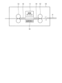
図1に示す画像読取装置10は、画像パターンが印字された記録媒体である被写体Pに、光源から光を照射し、被写体Pで反射された反射光を検出することによって、当該画像パターン等を読み取る装置である。図1では、被写体Pが、紙面視右側から左側に向かって搬送される状態が示されている。画像読取装置10は、図1に示すように、読取デバイス11と、第1搬送ローラ対12と、第2搬送ローラ対13と、搬送ガイド板14、15と、基準部材16と、を備える。
The
読取デバイス11は、被写体Pに光源から光を照射し、被写体Pで反射された反射光を検出することによって、当該画像パターン等を読み取るデバイスである。
The
第1搬送ローラ対12は、読取デバイス11より搬送路の上流側に配置され、被写体Pを読取デバイス11側へ搬送させるローラ対である。第2搬送ローラ対13は、読取デバイス11より搬送路の下流側に配置され、読取デバイス11により画像パターンが読み取られた被写体Pを下流側へ搬送させるローラ対である。
The first
搬送ガイド板14は、読取デバイス11より搬送路の上流側に配置され、被写体Pを搬送する際のガイドとなる部材であり、被写体Pの移動範囲を制限している。搬送ガイド板15は、読取デバイス11より搬送路の上流側に配置され、被写体Pを搬送する際のガイドとなる部材であり、被写体Pの移動範囲を制限している。
The
基準部材16は、読取デバイス11に対向する位置に配置され、基準色として読取デバイス11に読み取らせるための部材である。例えば、白色(低濃度)の基準部材16である場合、読取デバイス11が被写体Pを読み取った画像をシェーディング補正する際の基準データの生成に用いられる。また、黒色(高濃度)の基準部材16である場合、低濃度の被写体Pの端部を検出するために用いられる。なお、基準部材16は、白色の部材および黒色の部材等の複数の部材として、画像読取装置10のアプリケーションに応じて、用いる部材を駆動源によって切り替えるよう構成であってもよい。
The
(画像読取装置のブロック構成)
図2は、第1の実施形態に係る画像読取装置のブロック構成の一例を示す図である。図2を参照しながら、本実施形態に係る画像読取装置10のブロック構成について説明する。
(Block configuration of image reading device)
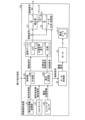
FIG. 2 is a diagram showing an example of a block configuration of the image reading device according to the first embodiment. The block configuration of the
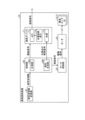
図2に示すように、画像読取装置10は、読取デバイス11と、制御部20と、被写体情報記憶部21(記憶部)と、モータ制御部22と、モータ23と、第1搬送ローラ対12と、第2搬送ローラ対13と、を備えている。
As shown in FIG. 2, the
読取デバイス11は、上述のように、被写体Pに光源から光を照射し、被写体P上で反射された反射光を検出することによって、当該画像パターン等を読み取る。読取デバイス11は、図2に示すように、光源11aと、光電変換素子11bと、AFE(Analog Front End)11cと、を有する。
As described above, the
光源11aは、被写体Pに印字された画像パターンを読み取るために、当該被写体Pに光を照射する光源である。光源11aは、制御部20から出力される光源点灯制御信号によって、任意のタイミングで点灯および消灯の制御が行われる。光源11aは、例えば、ハロゲンランプ、希ガス蛍光ランプ(キセノンランプ)またはLED(Light Emitting Diode)等である。なお、小型かつ低消費電力を実現するためには、ハロゲンランプおよび希ガス蛍光ランプに比べて、点灯(発光)に必要な専用インバータが不要となる単一または複数のLEDを光源11aとして用いることが望ましい。希ガス蛍光ランプは光量安定化に必要な時間として一般的に数十[ms]が必要であるのに対し、LEDは1[ms]未満であるため、点灯および消灯制御に対する応答性が速い。
The
光電変換素子11bは、被写体Pからの反射光を受光し、当該反射光を電気信号に変換する素子である。AFE11cは、光電変換素子11bにより変換された電気信号をデジタル信号である画像信号に変換する装置である。
The
制御部20は、画像読取装置10全体の動作を制御する制御装置である。制御部20は、例えば、電子回路により実装されるCPU(Central Processing Unit)のようにソフトウェアによって各機能を実行するようプログラミングされたプロセッサ、ASIC(Application Specific Integrated Circuit)、DSP(Digital Signal Processor)、FPGA(Field-Programmable Gate Array)、SoC(System on a Chip)、GPU(Graphics Processing Unit)、または従来の回路モジュール等のデバイスによって実現される。制御部20は、図2に示すように、計測部20aと、信号生成部20bと、を有する。
The
計測部20aは、被写体Pが搬送路上を搬送開始されてから経過した時間を計測する。信号生成部20bは、光源11aの点灯および消灯動作を制御するための光源点灯制御信号を生成する。
The
被写体情報記憶部21は、被写体Pの任意の端部を基準とした画像パターンの位置情報(被写体情報)を記憶する記憶装置である。光源11aの省電力および長寿命化を優先する動作モード(以下、第1動作モードと称する)では、被写体P上の画像パターンの位置情報に応じて、制御部20は、光源11aの点灯条件を変更制御する。また、印刷画像の色再現性および色安定性等についての高い品質および安定性を優先する動作モード(以下、第2動作モードと称する)では、被写体P上の画像パターンの位置情報によらず、制御部20は、光源11aの点灯条件を一定にするように制御する。
The subject
モータ制御部22は、モータ23を回転駆動させるための駆動信号を生成する駆動回路である。モータ23は、第1搬送ローラ対12および第2搬送ローラ対13を回転駆動させるモータである。
The
(第1動作モードでの光源点灯制御)
図3は、第1の実施形態における第1動作モードの光源点灯制御の主要信号のタイミングチャートの一例を示す図である。図4は、第1の実施形態における第1動作モードの光源点灯制御における点灯および消灯のタイミングを説明する図である。図3および図4を参照しながら、画像読取装置10における第1動作モードでの光源点灯制御について説明する。
(Light source lighting control in the first operation mode)
FIG. 3 is a diagram showing an example of a timing chart of main signals for light source lighting control in the first operation mode in the first embodiment. FIG. 4 is a diagram illustrating the timing of lighting and turning off the light in the light source lighting control in the first operation mode in the first embodiment. Light source lighting control in the first operation mode in the
被写体情報記憶部21は、上述のように、被写体Pの画像パターンの位置情報を記憶しており、例えば、図3に示す被写体Pの検出領域D1、D2それぞれの画像パターンの位置情報を記憶している。制御部20は、被写体情報記憶部21に記憶された検出領域D1、D2の画像パターンの位置情報を読み出す。そして、制御部20の信号生成部20bは、計測部20aにより計測される被写体Pの搬送開始からの時間に基づいて、検出領域D1、D2それぞれが読取デバイス11の読取位置を通過する期間のみ光源11aを点灯させるような光源点灯制御信号led_onを生成する。そして、光源11aは、信号生成部20bにより生成された光源点灯制御信号led_onに従って点灯および消灯動作を行う。
As described above, the subject
図3に示す例では、光源点灯制御信号のパターンとして、(a)および(b)の2つの例を示している。パターン(a)では、光源11aは、検出領域D1、D2のみを照射するような点灯制御が行われる。これによって、検出領域D1、D2という光の照射が必要な領域のみ光源11aを点灯させるので、光源11aの省電力および長寿命化を実現することが可能となる。なお、パターン(b)に示すように、検出領域D1、D2に対して確実に光を照射させるために、光源11aの点灯期間を副走査方向の前後に所定幅だけ拡大させる(マージンを持たせる)ものとしてもよい。
In the example shown in FIG. 3, two examples (a) and (b) are shown as patterns of the light source lighting control signal. In pattern (a), the
次に、図4を参照しながら、図3のパターン(a)の光源点灯制御信号で光源11aを制御する場合の点灯タイミングおよび消灯タイミングについて説明する。被写体Pの搬送速度、搬送基準位置(搬送開始位置)から読取デバイス11の読取位置までの距離、および検出領域D1、D2までの距離を、以下のように定める。
Next, with reference to FIG. 4, the lighting timing and lighting timing when controlling the
・被写体Pの搬送速度:V[mm/s]
・搬送基準位置(被写体P先端)から読取位置までの距離:D[mm]
・被写体P先端から検出領域D1先端までの距離:a[mm]
・被写体P先端から検出領域D1後端までの距離:b[mm]
・被写体P先端から検出領域D2先端までの距離:c[mm]
・被写体P先端から検出領域D2後端までの距離:d[mm]
・Transportation speed of subject P: V [mm/s]
・Distance from transport reference position (tip of subject P) to reading position: D [mm]
・Distance from the tip of the subject P to the tip of the detection area D1: a [mm]
・Distance from the tip of the subject P to the rear edge of the detection area D1: b [mm]
・Distance from the tip of subject P to the tip of detection area D2: c [mm]
・Distance from the tip of subject P to the rear edge of detection area D2: d [mm]
上記の速度および距離から、検出領域D1、D2それぞれが読取位置を通過する期間のみ光源11aを点灯させ、検出領域D1、D2以外の領域が読取位置を通過する期間は光源11aを消灯させる制御を行う場合、光源11aの点灯および消灯のタイミングは、以下のように算出される。ただし、被写体P先端が搬送基準位置にある場合の時間を0[s]とする
Based on the above speed and distance, the
・検出領域D1の点灯タイミング:(D+a)/V[s]
・検出領域D1の消灯タイミング:(D+b)/V[s]
・検出領域D2の点灯タイミング:(D+c)/V[s]
・検出領域D2の消灯タイミング:(D+d)/V[s]
・Lighting timing of detection area D1: (D+a)/V[s]
・Turn off timing of detection area D1: (D+b)/V[s]
・Lighting timing of detection area D2: (D+c)/V[s]
・Turn off timing of detection area D2: (D+d)/V[s]
このように、第1動作モードでは、被写体情報記憶部21に記憶された画像パターンの位置情報に従って、少なくとも検出領域が読取位置を通過している間のみ光源11aを点灯させることによって、光源11aの省電力および長寿命化を実現することができる。
As described above, in the first operation mode, the
なお、上述では、検出領域D1、D2以外の領域が読取位置を通過する期間は光源11aを消灯させるとしたが、必ずしも消灯させる必要はなく、例えば、光源11aの点灯状態を維持したまま、検出領域D1、D2の読取り時の光量よりも、所定の比率だけ低くした光量で点灯する制御としてもよい。
Note that in the above description, the
(第2動作モードでの光源点灯制御)
図5は、光源の点灯開始以降の輝度変化を説明する図である。図5を参照しながら、第2動作モードでの光源点灯制御の説明に先立って、光源11aの点灯開始以降の輝度変化について説明する。
(Light source lighting control in second operation mode)
FIG. 5 is a diagram illustrating a change in brightness after the light source starts lighting. With reference to FIG. 5, prior to explaining the light source lighting control in the second operation mode, changes in brightness after the
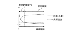
図5に示すように、光源11aは、点灯直後から自己発熱を主要因として輝度は著しく低下し、次第に光源温度の上昇が飽和状態に近づいていくと共に、輝度変化も緩やかになることが一般に知られている。ここで、図5に示すように、光源11aの点灯直後から輝度の変化が著しく安定しない期間を非安定期間T1とし、非安定期間T1以降の輝度が安定した期間を安定期間と称する。
As shown in FIG. 5, it is generally known that immediately after the
図6は、第1動作モードの光源点灯制御がデメリットとなる場合の一例を説明する図である。次に、図6を参照しながら、図5に示したように光源11aの点灯には非安定期間T1が存在することにより、第1動作モードによる光源11aの点灯制御がデメリットとなる場合について説明する。
FIG. 6 is a diagram illustrating an example of a case where the light source lighting control in the first operation mode is disadvantageous. Next, with reference to FIG. 6, a case will be explained in which the lighting control of the
光源11aの点灯制御においては、光源11aの光量変化を極力抑制して、高品質かつ安定した読取り動作が要求されるケースも考えられる。したがって、図6に示すように、被写体P上に互いの間隔が狭い態様(例えば、少なくとも図3に示した検出領域D1と検出領域D2との間隔よりも狭い態様)で検出領域D11~D14が配列されている場合、上述の第1動作モードのうち図3のパターン(a)により光源11aの点灯制御を行うと、すなわち、被写体Pの検出領域D11~D14に対応するように光源11aの点灯および消灯が行われると、検出領域D11~D14に対する読み取り期間内において、光源温度変化に伴う輝度(光量)の急激な変化により、読み取り結果の安定性を損なう可能性がある。
In controlling the lighting of the
図7は、第1の実施形態における第2動作モードの光源点灯制御の主要信号のタイミングチャートの一例を示す図である。図7を参照しながら、画像読取装置10における第2動作モードでの光源点灯制御について説明する。
FIG. 7 is a diagram showing an example of a timing chart of main signals for light source lighting control in the second operation mode in the first embodiment. Light source lighting control in the second operation mode in the
図6で上述した第1動作モードでのデメリットを回避して、高品質かつ安定した読取り動作を実現するために、制御部20は、第2動作モードによる光源点灯制御を実行し、被写体情報記憶部21に記憶された画像パターンの位置情報を考慮せずに、所定の点灯条件により各検出領域(検出領域D11~D14)を読み取るようにすればよい。具体的には、まず、制御部20は、図7に示すように、被写体Pの検出領域D11が読取位置を通過するまでに非安定期間T1が既に経過している状態となるように光源11aを点灯させる。そして、制御部20は、検出領域D11~D14のすべてが読取位置を通過するまでの期間内では、光源11aを消灯して点灯させるような動作を一切行わないように点灯制御を行う。
In order to avoid the disadvantages of the first operation mode described above in FIG. 6 and achieve high quality and stable reading operation, the
このように、第2動作モードでは、被写体情報記憶部21に記憶された画像パターンの位置情報によらず、被写体Pが読取位置を通過している間は点灯条件を一定にして光源11aを点灯させることによって、高品質かつ安定した読取り動作を行うことができる。
In this way, in the second operation mode, the lighting conditions are kept constant and the
以上のように、本実施形態に係る画像読取装置10は、第1動作モードおよび第2動作モードそれぞれにおいて、被写体情報記憶部21に記憶された画像パターンの位置情報を参照し、適宜、光源11aの点灯条件を切り替えて制御するものとしているので、画像読取装置10としての総合的なパフォーマンスを向上させ、ひいては印刷画像の品質を総合的に向上させることができる。
As described above, in each of the first operation mode and the second operation mode, the
なお、画像読取装置10は、被写体情報記憶部21に記憶された画像パターンに基づいて、第1動作モードと第2動作モードとを適宜切り替えるものとしてもよい。例えば、画像読取装置10は、画像パターンの位置情報が、検出領域(画像パターンを読み取る領域)の間隔が閾値よりも大きいことを示す場合、第1動作モードに切り替え、当該間隔が閾値よりも小さいことを示す場合、第2動作モードに切り替えるものとしてもよい。または、画像読取装置10は、画像パターンの位置情報が示す検出領域の間隔が、光源11aの点灯時における非安定期間T1よりも大きい場合、検出領域と検出領域との間において消灯および再点灯した際に非安定期間T1を経過させた上で次の検出領域を読み取ることができると判断し、第1動作モードに切り替えるものとしてもよい。そして、画像読取装置10は、画像パターンの位置情報が示す検出領域の間隔が、光源11aの点灯時における非安定期間T1よりも小さい場合、検出領域と検出領域との間において消灯および再点灯した際に、次の検出領域の読み取りまでに非安定期間T1が経過しないと判断し、第2動作モードに切り替えるものとしてもよい。
Note that the
また、上述の実施形態では、光源11aの省電力および長寿命化を優先する第1動作モード、および印刷画像の色再現性および色安定性等についての高い品質および安定性を優先する第2動作モードの2つの動作モードについて説明したが、これに限定されない。すなわち、処理負荷の軽減を優先する動作モード、または処理速度の向上を優先する動作モード等の他の動作モードも有するものとしてもよい。
Further, in the above-described embodiment, the first operation mode prioritizes power saving and longevity of the
[第2の実施形態]
第2の実施形態に係る画像読取装置について、第1の実施形態に係る画像読取装置10と相違する点を中心に説明する。第1の実施形態では、制御部20が、時間に基づいて光源11aを点灯させるか消灯させるかを規定する光源点灯制御信号を生成する動作を説明した。本実施形態では、被写体Pに移動量に基づいて光源点灯制御信号を生成する動作について説明する。
[Second embodiment]
The image reading apparatus according to the second embodiment will be described with a focus on the differences from the
(画像読取装置のブロック構成)
図8は、第2の実施形態に係る画像読取装置のブロック構成の一例を示す図である。図8を参照しながら、本実施形態に係る画像読取装置10aのブロック構成について説明する。
(Block configuration of image reading device)
FIG. 8 is a diagram illustrating an example of a block configuration of an image reading device according to the second embodiment. The block configuration of the
図8に示すように、画像読取装置10aは、読取デバイス11と、制御部20と、被写体情報記憶部21と、モータ制御部22と、モータ23と、フォトセンサ24と、エンコーダセンサ25(位置検出部の一例)と、第1搬送ローラ対12と、第2搬送ローラ対13と、を備えている。
As shown in FIG. 8, the
フォトセンサ24は、搬送路上を搬送される被写体Pの有無を検出するセンサである。フォトセンサ24は、被写体Pの有無を示す信号として被写体有無検出信号を出力する。
The
エンコーダセンサ25は、被写体Pと読取デバイス11(読取位置)との相対的な位置関係を計測するセンサである。エンコーダセンサ25は、被写体Pと読取デバイス11(読取位置)との相対的な位置関係を示す搬送位置情報としてパルス信号を出力する。
The
制御部20の計測部20aは、フォトセンサ24により被写体Pが検出されてから、エンコーダセンサ25から出力されるパルス信号の計測を開始する。制御部20の信号生成部20bは、計測部20aにより計測されるパルス信号に基づいて、光源11aの点灯および消灯を制御する光源点灯制御信号を生成する。
The
なお、図8に示すその他のブロックの動作は、第1の実施形態で上述した通りである。 Note that the operations of the other blocks shown in FIG. 8 are as described above in the first embodiment.
(画像読取装置の概略構造)
図9は、第2の実施形態に係る画像読取装置の概略構造の一例を示す図である。図9を参照しながら、本実施形態に係る画像読取装置10aの概略構成について説明する。
(Schematic structure of image reading device)
FIG. 9 is a diagram illustrating an example of a schematic structure of an image reading device according to the second embodiment. Referring to FIG. 9, a schematic configuration of an
画像読取装置10aは、図9に示すように、読取デバイス11と、第1搬送ローラ対12と、エンコーダディスク12aと、第2搬送ローラ対13と、フォトセンサ24と、エンコーダセンサ25と、を備える。なお、図9では図示していないが、画像読取装置10aは、さらに、搬送ガイド板14、15と、基準部材16と、を備える。
As shown in FIG. 9, the
フォトセンサ24は、読取デバイス11および第1搬送ローラ対12よりも搬送路の上流側に配置され、被写体Pの先端がフォトセンサ24の検出位置に到達してから、被写体Pの後端が当該検出位置を過ぎるまで被写体Pが有ると検出し、それ以外は、被写体Pがないと検出する。
The
エンコーダセンサ25は、第1搬送ローラ対12の回転軸上に備えられたエンコーダディスク12aに設けられた多数のスリットの有無を検出することによって、パルス信号を出力する。
The
(光源点灯制御)
図10は、第2の実施形態における光源点灯制御の主要信号のタイミングチャートの一例を示す図である。図10を参照しながら、画像読取装置10aにおける光源点灯制御について説明する。ここでは、第1動作モードにおける光源点灯制御とする。
(Light source lighting control)
FIG. 10 is a diagram showing an example of a timing chart of main signals for light source lighting control in the second embodiment. Light source lighting control in the
フォトセンサ24は、上述の通り、被写体Pの有無によって変化する被写体検出信号ph_sensorを、制御部20へ出力する。エンコーダセンサ25は、上述の通り、エンコーダディスク12aの回転量に応じたパルス信号enc_sensorを出力する。
As described above, the
そして、制御部20の計測部20aは、上述のように、フォトセンサ24により被写体Pが検出されてから、エンコーダセンサ25から出力されるパルス信号の計測を開始する。また、制御部20の信号生成部20bは、計測部20aにより計測されるパルス信号に基づいて、光源11aの点灯および消灯を制御する光源点灯制御信号led_onを生成する。
Then, as described above, the
具体的には、制御部20は、計測部20aにより計測されたパルス信号の計測結果に基づいて、フォトセンサ24により被写体Pが検出されてから、図10に示す画像パターンを含む検出領域D20の副走査方向の先端位置に読取デバイス11の読取位置が到達したタイミング(パルスカウント期間PT1が経過したタイミング)で、光源点灯制御信号により光源11aの点灯を開始する。ここで、パルスカウント期間PT1は、例えば、被写体Pの副走査方向の先端位置から、検出領域D20の副走査方向の先端位置までの距離に基づいて決定されるものとすればよい。
Specifically, the
同様に、制御部20は、計測部20aにより計測されたパルス信号の計測結果に基づいて、フォトセンサ24により被写体Pが検出されてから、検出領域D20の副走査方向の後端位置に読取デバイス11の読取位置が到達したタイミング(パルスカウント期間PT2が経過したタイミング)で、光源点灯制御信号により光源11aを消灯させる。ここで、パルスカウント期間PT2は、例えば、被写体Pの副走査方向の先端位置から、検出領域D20の副走査方向の後端位置までの距離に基づいて決定されるものとすればよい。
Similarly, the
ここで、例えば、制御部20が、フォトセンサ24により被写体Pが検出されたタイミングを起点として時間に基づく光源点灯制御信号によって光源点灯制御を行う場合、制御部20の処理負荷次第では、割込みに対する実行遅延が生じたり、内蔵のタイマの誤差(ばらつき)の影響を受けたりすること等により、光源11aの点灯および消灯のタイミングにばらつきが生じる虞がある。さらに、被写体Pの種類、および搬送路を構成する部品によっては、被写体Pの搬送速度が必ずしも一定とは限らない。そのため、上記の様々な変動要因を考慮した光源11aの光源点灯制御が必要となり、商用印刷市場における高速かつ高生産性が要求される製品においては、光源点灯制御を成立させる難易度が非常に高くなる。
Here, for example, when the
そこで、本実施形態に係る画像読取装置10aは、上述のように、被写体Pの画像パターンを含む検出領域の読み取りに必要な光源11aの点灯および消灯のタイミングを、被写体Pの副走査方向の移動量に基づいて制御するものとしている。これによって、副走査方向の移動量に基づいた制御方式であるため、制御部20の処理負荷、および搬送路における被写体Pの搬送速度の影響を受けずに、高精度かつ安定性の高い制御を実現できる。この結果、第1動作モードにおいて、必ずしも被写体P全面に光源11aによる光の照射が必要のない場合において、必要な画像パターンの領域(検出領域)のみ対して光を照射する制御が高精度に可能となり、その結果として光源11aにおける省電力および長寿命化の効果を奏することが可能となる。
Therefore, as described above, the
[第3の実施形態]
第3の実施形態に係る画像読取装置について、第2の実施形態に係る画像読取装置10aと相違する点を中心に説明する。第2の実施形態では、被写体Pにおける検出領域のみに対して光源11aによる点灯を行う制御について説明した。本実施形態では、光源11aの点灯後の輝度変化を考慮した光源点灯制御について説明する。なお、本実施形態に係る画像読取装置の構造およびブロック構成は、第2の実施形態に係る画像読取装置10aと同様である。
[Third embodiment]
The image reading device according to the third embodiment will be described with a focus on the differences from the
(第1動作モードでの光源点灯制御)
図11は、第3の実施形態における第1動作モードの光源点灯制御の主要信号のタイミングチャートの一例を示す図である。図11を参照しながら、本実施形態に係る画像読取装置における第1動作モードでの光源点灯制御について説明する。
(Light source lighting control in the first operation mode)
FIG. 11 is a diagram showing an example of a timing chart of main signals for light source lighting control in the first operation mode in the third embodiment. Light source lighting control in the first operation mode in the image reading device according to the present embodiment will be described with reference to FIG. 11.
上述の図5で説明したように、光源11aは、点灯直後から自己発熱を主要因として輝度は著しく低下し、次第に光源温度の上昇が飽和状態に近づいていくと共に、輝度変化も緩やかになることが一般に知られている。光源11aの部品仕様によって、温度変化量、および、それに伴う輝度変化量は異なるが、実使用上問題のない範囲で輝度が安定するまで時間を、上述のように非安定期間T1として考える。
As explained in FIG. 5 above, immediately after the
本実施形態において、制御部20は、図5に示した非安定期間T1を、エンコーダセンサ25から出力されるパルス信号のパルス数NT1に換算して制御する。この場合、被写体Pの搬送速度をV[mm/s]、非安定期間をT1[s]とすると、光源11aが点灯してから輝度が安定するまでの必要な距離DT1は、以下の式(1)により算出される。
In this embodiment, the
DT1[mm]=V×T1 ・・・(1) DT1 [mm]=V×T1...(1)
また、エンコーダセンサ25から出力されるパルス信号のパルス間の移動距離d[mm]とすると、光源11aが点灯してから輝度が安定するまでに必要なパルス数NT1は、以下の式(2)により算出される。
Furthermore, assuming that the moving distance between the pulses of the pulse signal output from the
NT1=DT1/d ・・・(2) NT1=DT1/d...(2)
したがって、制御部20は、図11に示すように、フォトセンサ24により被写体Pが検出された位置から、検出領域D31の副走査方向の先端位置に読取デバイス11の読取位置が到達するまでの被写体Pの搬送距離から、パルス数NT1に相当する距離を差し引いた距離が、パルスカウント期間PT1に対応するものとして制御すればよい。
Therefore, as shown in FIG. 11, the
なお、図11に示すように、制御部20による光源11aの消灯タイミングは、検出領域D31の副走査方向の下端が読取デバイス11の読取位置に到達したタイミングとなっているが、これに限定されるものではなく、検出領域D31の副走査方向の下流側で光源11aを消灯させる動作であってもよい。
Note that, as shown in FIG. 11, the timing for turning off the
(第2動作モードでの光源点灯制御)
図12は、第3の実施形態における第2動作モードの光源点灯制御の主要信号のタイミングチャートの一例を示す図である。図12を参照しながら、本実施形態に係る画像読取装置における第2動作モードでの光源点灯制御について説明する。
(Light source lighting control in second operation mode)
FIG. 12 is a diagram showing an example of a timing chart of main signals for light source lighting control in the second operation mode in the third embodiment. Light source lighting control in the second operation mode in the image reading device according to the present embodiment will be described with reference to FIG. 12.
図11で上述した第1動作モードにおける光源点灯制御(被写体Pの検出領域の上流側で光源11aの点灯、検出領域の下端(下流)で光源11aの消灯)は、第2動作モードにも適用可能である。
The light source lighting control in the first operation mode described above in FIG. 11 (
例えば、図12に示すように、検出領域D32の副走査方向の幅が、被写体Pのほぼ全域を占めるような場合、被写体P上で非安定期間T1を確保するのは困難であり、光源11aの点灯開始のタイミングは、被写体P外(被写体Pの副走査方向の上端が読取位置に到達する前)になる。ただし、被写体P外で光源11aの点灯を開始させるのは、上述のように光源11aの輝度を安定化させるためであるので、特段問題はない。
For example, as shown in FIG. 12, when the width of the detection area D32 in the sub-scanning direction occupies almost the entire area of the subject P, it is difficult to secure the unstable period T1 on the subject P, and the
さらに、光源11aの消灯のタイミングは、必ずしも、検出領域D32の副走査方向の下端に合わせる必要はなく、制御部20による制御の簡素化を図り、被写体P外(被写体Pの副走査方向の下端が読取位置を通過した後)であってもよい。
Furthermore, the timing of turning off the
以上のことから、上述の図10で説明した第1動作モードにおける光源点灯制御は、第2動作モードにおいても適用可能である。 From the above, the light source lighting control in the first operation mode described above with reference to FIG. 10 is also applicable to the second operation mode.
以上のように、本実施形態に係る画像読取装置は、被写体Pの検出領域の副走査方向の先端から、非安定期間T1に相当する距離だけ上流側の位置で光源11aの点灯を開始させる制御を行っている。すなわち、制御部20は、光源11aの点灯を開始してから所定時間(例えば非安定期間T1)経過後に被写体P上の画像パターン(検出領域)が読取デバイス11の読取位置に到達するように、光源11aの点灯制御を行うものとしている。当該制御は、第1動作モードおよび第2動作モードの双方に適用可能である。上述のように、光源11aの点灯直後から所定時間が経過するまでは温度変化が大きく、光源輝度および発光スペクトルの変化も大きいという光源11aの特性があるが、本実施形態に係る画像読取装置は、このような輝度等の変化が激しい期間を非安定期間T1とし、当該非安定期間T1では、検出領域の読み取りを行わないように光源点灯制御を行うので、高い品質および安定性を実現すると共に、光源11aの省電力および長寿命化を実現することができる。
As described above, the image reading device according to the present embodiment performs control to start lighting the
[第4の実施形態]
第4の実施形態に係る画像読取装置について、第3の実施形態に係る画像読取装置と相違する点を中心に説明する。第3の実施形態では、光源11aの点灯開始からの輝度変化の一般的な特性を考慮した光源点灯制御について説明した。本実施形態では、光源11aの周辺の温度変化等の状況により特性が変化した場合の光源点灯制御について説明する。なお、本実施形態に係る画像読取装置の構造およびブロック構成は、第2の実施形態に係る画像読取装置10aと同様である。
[Fourth embodiment]
The image reading device according to the fourth embodiment will be described with a focus on the differences from the image reading device according to the third embodiment. In the third embodiment, light source lighting control has been described that takes into consideration the general characteristics of luminance changes from the start of lighting of the
(雰囲気温度変化による影響下での光源の特性変化)
図13は、雰囲気温度変化の影響を受けた光源の点灯開始以降の輝度変化を説明する図である。図13を参照しながら、雰囲気温度変化による影響下での光源11aの特性変化について説明する。
(Characteristics change of light source under the influence of ambient temperature change)
FIG. 13 is a diagram illustrating a change in brightness after the start of lighting of a light source affected by a change in ambient temperature. With reference to FIG. 13, a change in the characteristics of the
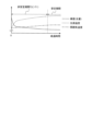
光源11aは、自己発熱だけではなく、周辺の部品の動作に伴う雰囲気の温度の上昇等がある場合、図13に示すように、雰囲気温度変化(図13に示す例では温度が上昇した場合)の影響を受け、光源温度の飽和までに時間を要し(非安定期間T2>T1)、図5に示した非安定期間T1では読取デバイス11による十分な読み取り性能が得られない場合がある。これに対応するための光源点灯制御を、以下の図14および図15で後述する。
As shown in FIG. 13, the
(画像読取装置のブロック構成)
図14は、第4の実施形態に係る画像読取装置のブロック構成の一例を示す図である。図14を参照しながら、本実施形態に係る画像読取装置10bのブロック構成について説明する。
(Block configuration of image reading device)
FIG. 14 is a diagram illustrating an example of a block configuration of an image reading device according to the fourth embodiment. The block configuration of the image reading device 10b according to this embodiment will be described with reference to FIG. 14.
図14に示すように、画像読取装置10bのブロック構成は、図8に示した第2の実施形態に係る画像読取装置10aのブロック構成と同様である。ただし、制御部20は、外部信号を受信するためのインターフェースを有し、図14に示すように、当該インターフェースを介して、外部信号である実行指示信号を受信する。
As shown in FIG. 14, the block configuration of the image reading device 10b is similar to the block configuration of the
制御部20の信号生成部20bは、上述のインターフェースを介して実行指示信号を受信した後に、光源11aを点灯させるような光源点灯制御信号を生成する。例えば、画像読取装置10bが、外部からの指令により画像読取動作の開始指令を受けた場合、外部から実行指示信号が制御部20に入力される。すなわち、制御部20は、画像読取装置10bが画像読取動作を開始した後に、光源11aを点灯させる。
After receiving the execution instruction signal via the above-mentioned interface, the
(光源点灯制御)
図15は、第4の実施形態における光源点灯制御の主要信号のタイミングチャートの一例を示す図である。図15を参照しながら、画像読取装置10bにおける光源点灯制御について説明する。
(Light source lighting control)
FIG. 15 is a diagram showing an example of a timing chart of main signals for light source lighting control in the fourth embodiment. Light source lighting control in the image reading device 10b will be described with reference to FIG. 15.
本実施形態に係る画像読取装置10bでは、図15に示すように、制御部20に実行指示信号actが入力された(有効となった)タイミングを契機に、光源11aは、光源点灯制御信号led_onにより点灯を開始する。その後の画像読取装置10bの動作は、第2の実施形態および第3の実施形態と同様である。 In the image reading device 10b according to the present embodiment, as shown in FIG. Starts lighting. The subsequent operation of the image reading device 10b is the same as in the second embodiment and the third embodiment.
なお、図15では、第1動作モードの動作を例が示されているが、これに限定されるものではなく、第2動作モードにも適用が可能であり、被写体Pが読取デバイス11の読取位置を通過してから光源11aが消灯する制御であってもよい。
Although FIG. 15 shows an example of the operation in the first operation mode, it is not limited to this, and the application is also possible in the second operation mode, in which the subject P is read by the
以上のように、画像読取装置10bは、外部の実行指示信号を受信した後、光源11aの点灯を開始することによって、光源11aの光源温度が十分に飽和した状態で、検出領域D40の読み取りを行うことができ、安定性の高い読み取りを行うことができる。
As described above, after receiving the external execution instruction signal, the image reading device 10b starts lighting the
なお、上述では制御部20に実行指示信号が入力されるのは、画像読取装置10bによる画像読取動作が開始した場合としているが、これに限定されるものではない。例えば、読取デバイス11による被写体Pの検出領域の読み取りが開始される前に、図13に示した非安定期間T2が十分に経過するようなタイミングであれば、どのような実行指示信号の入力タイミングであってもよい。
Note that, in the above description, the execution instruction signal is input to the
[第5の実施形態]
第5の実施形態に係る画像読取装置について、第2の実施形態に係る画像読取装置10aと相違する点を中心に説明する。第2の実施形態では、第1動作モードにおいて、被写体Pの検出領域の読み取りを行うための光源11aの点灯および消灯についての光源点灯制御について説明した。本実施形態では、被写体Pの端部、または、被写体P上の検出領域(画像パターンを含む領域)の端部の検出を第1動作モードで行う場合について説明する。なお、本実施形態に係る画像読取装置の構造およびブロック構成は、第2の実施形態に係る画像読取装置10aと同様である。
[Fifth embodiment]
The image reading device according to the fifth embodiment will be described with a focus on the differences from the
(被写体端部または検出領域の端部の検出動作)
図16は、被写体端部および画像パターンの位置の検出の概要について説明する図である。図17は、第5の実施形態において副走査方向の被写体端部の位置の検出動作を説明する図である。図18は、第5の実施形態において副走査方向の被写体端部の位置の読取値の変動を説明する図である。図16~図18を参照しながら、被写体Pの端部、または被写体P上の検出領域の端部を検出する動作について説明する。
(Detection operation of the edge of the object or the edge of the detection area)
FIG. 16 is a diagram illustrating an overview of detecting the position of the object edge and the image pattern. FIG. 17 is a diagram illustrating the operation of detecting the position of the object end in the sub-scanning direction in the fifth embodiment. FIG. 18 is a diagram illustrating fluctuations in the read value of the position of the object end in the sub-scanning direction in the fifth embodiment. The operation of detecting the edge of the subject P or the edge of the detection area on the subject P will be described with reference to FIGS. 16 to 18.
図16に示すように、画像読取装置では、被写体Pの外形、または、被写体P上の画像パターンが印字された画像領域の外形を検出する要請がある。例えば、読取デバイス11を用いて、図16に示すように、被写体Pの端部位置を検出することにより、被写体Pの四隅の座標を検出し、外形形状を推定する技術は、既に開示されている。また、同様の方法により、読取デバイス11を用いて、図16に示すように、被写体Pの画像領域(検出領域)の端部を検出することにより、画像領域の四隅の座標を特定し、外形形状を推定することが可能である。以下、本実施形態に係る画像読取装置において、制御部20により、第1動作モードで、被写体Pの端部位置を検出する動作について説明する。
As shown in FIG. 16, there is a need for an image reading device to detect the outline of a subject P or the outline of an image area on which an image pattern is printed on the subject P. For example, as shown in FIG. 16, a technique for detecting the coordinates of the four corners of the subject P and estimating the external shape by detecting the edge position of the subject P using the
図17では、読取デバイス11の対向位置に、背景となる略黒色(高濃度)の部材(図1の基準部材16)が配置され、略白色(低濃度)の被写体Pを読み取る場合の状態を示している。本実施形態に係る画像読取装置は、被写体Pの略四隅の副走査方向の端部位置を検出すべく、副走査方向の端部位置を含む検出領域D51~D54について副走査方向で読み取り動作を可能とするための光源点灯制御を行う。当該光源点灯制御信号については、また、制御部20は、読取デバイス11により各検出領域(検出領域D51~D54)に対する読み取り動作が行われる場合に、図17に示すように、光源11aの点灯期間の光量は一定ではなく、点灯開始から消灯にかけて低下しているものとする。
In FIG. 17, a substantially black (high density) member serving as a background (
図18では、上述のような制御部20による光源点灯制御が行われる場合に、検出領域D51または検出領域D52が読み取られた際の、読取値の時間方向(副走査方向)の変動を示すグラフを示している。上述のように、光源11aの点灯期間での光量は徐々に低下しているため、読取デバイス11により読み取られる光量も追従して変動(低下)する。しかし、単に被写体Pの端部を検出することが目的であれば、図18に示すように、所定の閾値と、背景(黒)から被写体P(白)への変化するグラフ部分の交点を、被写体Pの端部として容易に検出できるため、多少の読取値の変動が発生しても、被写体Pの端部の検出動作への影響は小さい。
In FIG. 18, a graph showing a change in the read value in the time direction (sub-scanning direction) when the detection area D51 or the detection area D52 is read when the light source lighting control is performed by the
なお、図18では、被写体Pの端部位置の検出について説明したが、被写体P上の画像パターン(検出領域)の端部位置を検出する場合も、上述と同様の方法により検出することができる。 Note that although FIG. 18 describes the detection of the edge position of the subject P, the edge position of the image pattern (detection area) on the subject P can also be detected by the same method as described above. .
以上のように、本実施形態に係る画像読取装置では、被写体Pの端部位置、または、被写体P上の画像パターン(検出領域)の端部位置の検出において、第1動作モードを適用することにより、光源11aの省電力および長寿命化を実現することができる。
As described above, in the image reading device according to the present embodiment, the first operation mode is applied in detecting the edge position of the subject P or the edge position of the image pattern (detection area) on the subject P. This makes it possible to save power and extend the life of the
[第6の実施形態]
本実施形態では、被写体Pに複数の濃度で形成された画像パターンを読み取る動作について説明する。なお、本実施形態に係る画像読取装置は、例えば、第2の実施形態に係る画像読取装置10aと同様の構成を有する。
[Sixth embodiment]
In this embodiment, an operation of reading an image pattern formed on a subject P at a plurality of densities will be described. Note that the image reading device according to the present embodiment has, for example, the same configuration as the
(複数の濃度で画像パターンが形成された被写体について)
図19は、複数濃度の画像パターンが印字された被写体の一例を示す図である。図19を参照しながら複数の濃度で画像パターンが形成(印字)された被写体Pについて説明する。
(For subjects with image patterns formed with multiple densities)
FIG. 19 is a diagram showing an example of a subject on which image patterns of multiple densities are printed. A subject P on which image patterns are formed (printed) at a plurality of densities will be described with reference to FIG. 19.
読取デバイス11を用いて被写体P上の所定の画像パターンを読み取ることにより、画像パターンの濃度情報を検出する技術が知られている。例えば、図19に示すように、複数階調の濃度の画像パターンを所定間隔で配置し、全階調の読取値に基づいて、被写体の印刷条件(トナーまたはインク等の濃度条件)の補正等に応用される。図19に示す被写体Pの例では、紙面視上側から濃度75[%]、60[%]、50[%]、35[%]、20[%]の5階調の濃度の画像パターンが印字されている。なお、被写体Pへの印刷(画像形成)を行う装置は、本実施形態に係る画像読取装置を備えた画像形成装置であってもよく、別の画像形成装置であってもよい。
A technique is known in which density information of an image pattern is detected by reading a predetermined image pattern on the subject P using the
(複数の濃度の画像パターンの検出動作)
図20は、複数濃度の画像パターンを検出する際の第1動作モードおよび第2動作モードの適用例を示す図である。図21は、第1動作モードおよび第2動作モードにおける各濃度に対する読取値のグラフの一例を示す図である。図20および図21を参照しながら、複数の濃度の画像パターンについて第1動作モードおよび第2動作モードそれぞれにおいて検出する動作について説明する。
(Detection operation of image patterns with multiple densities)
FIG. 20 is a diagram showing an example of application of the first operation mode and the second operation mode when detecting an image pattern of multiple densities. FIG. 21 is a diagram showing an example of a graph of reading values for each concentration in the first operation mode and the second operation mode. The operation of detecting image patterns of a plurality of densities in the first operation mode and the second operation mode will be described with reference to FIGS. 20 and 21.
図20における(a)は、第1動作モードによる光源点灯制御が行われた場合の光源11aの光量変動を示すグラフであり、(b)は、第2動作モードによる光源点灯制御が行われた場合の光源11aの光量変動を示すグラフである。第1動作モードによる光源点灯制御(図20の(a))の場合、濃度75[%]の検出領域D61の端部近傍から光源11aの点灯が開始されているので、光源11aの光量の安定化に多少の時間を要しており、濃度60[%]の検出領域D62の途中以降で光量が安定する安定期間に移行している。一方、第2動作モードによる光源点灯制御(図20の(b))の場合、被写体Pの上端が読取デバイス11の読取位置に到達する前に光源11aの点灯が開始されており、濃度75[%]の検出領域D61の端部が読取位置に到達する前に、光源11aの点灯が開始されているので、検出領域D61の端部が読取位置に到達する前には、光源11aの光量が安定している安定期間に移行している。なお、図20に示すように、各濃度の検出領域について、濃度75[%]は検出領域D61、濃度60[%]は検出領域D62、濃度50[%]は検出領域D63、濃度35[%]は検出領域D64、濃度20[%]は検出領域D65としている。
In FIG. 20, (a) is a graph showing the light intensity fluctuation of the
第1動作モードおよび第2動作モードにおいて上述のような光源11aに対する光源点灯制御が行われた場合の、各検出領域に対する読取値について、図21にグラフを示し、具体的な読取値の一例を下記の(表1)に示す。なお、読取値とは、図20に示した各検出領域(検出領域D61~D65)内の読取値の平均値(主走査方向および副走査方向の複数画素群の平均値)である。
FIG. 21 shows a graph of the read values for each detection area when the light source lighting control for the

図21および(表1)に示すように、第1動作モードでは、濃度75[%]、60[%]の検出領域D61、D62では、光量の安定期間ではないため、第2動作モード適用時と比較して、読取デバイス11は、やや光量過多で読み取ることになり、読取値はややたかめの値となる。すなわち、高濃度領域において誤差を有することになる。
As shown in FIG. 21 and (Table 1), in the first operation mode, the detection areas D61 and D62 with densities of 75% and 60% are not stable periods of light intensity, so when the second operation mode is applied, In comparison, the
なお、図19および図20に示す被写体Pの例では、グレースケールによる複数階調の濃度の画像パターンを示したが、これに限定されない。例えば、赤、緑、青といった光の3原色、シアン、マゼンタ、イエローといった色の3原色、または、上記の色の任意の混色の濃度(色)情報であっても、同様のことが言える。 Note that in the example of the subject P shown in FIGS. 19 and 20, an image pattern with multiple gradations of density based on gray scale is shown, but the present invention is not limited to this. For example, the same can be said of the density (color) information of the three primary colors of light such as red, green, and blue, the three primary colors of cyan, magenta, and yellow, or any mixture of the above colors.
上述のように、複数の濃度で画像パターンが形成(印字)された被写体Pについて読み取りを行う場合に第1動作モードを適用した場合において、光量の安定期間ではない期間に光量過多で読み取ってしまうことがあるため、補正対象である画像形成装置の画像形成条件に問題がないにもかかわらず、画像形成条件の補正が必要であるという誤判定を招来する可能性がある。これに対して、複数の濃度で画像パターンが形成(印字)された被写体Pについて読み取りを行う場合に第2動作モードを適用することによって、高品質かつ安定した読取り動作を実現することができる。 As described above, when the first operation mode is applied when reading an object P on which image patterns are formed (printed) at multiple densities, reading occurs due to excessive light intensity during a period when the light intensity is not stable. Therefore, even though there is no problem with the image forming conditions of the image forming apparatus to be corrected, there is a possibility that an erroneous determination may be made that the image forming conditions need to be corrected. On the other hand, by applying the second operation mode when reading the object P on which image patterns are formed (printed) in a plurality of densities, it is possible to realize a high-quality and stable reading operation.
[第7の実施形態]
第7の実施形態に係る画像読取装置について、第4の実施形態に係る画像読取装置10bと相違する点を中心に説明する。本実施形態では、第4の実施形態に係る画像読取装置10bの構成に対して、読取デバイス11から出力される画像信号に対して白シェーディング補正処理を行う構成を加えた画像読取装置について説明する。
[Seventh embodiment]
The image reading device according to the seventh embodiment will be described with a focus on the differences from the image reading device 10b according to the fourth embodiment. In this embodiment, an image reading apparatus will be described in which a configuration for performing white shading correction processing on an image signal output from the
CIS(Contact Image Sensor:密着型イメージセンサ)に代表される読取デバイスでは、主走査方向に分光反射率(濃度)が均一である被写体を読み取った際に得られるセンサ出力信号量は、主走査方向に変化する特性を示すことで知られている。このような主走査方向の変化(以降、主走査照度分布と呼ぶ)が発生する要因としては、LED等の光源を入射させて主走査方向に被写体に照射するための導光体の形状、導光体とその他周辺部品との組立位置関係、被写体との位置関係、読取デバイスが備えるセンサ(光電変換素子)自身の感度特性のばらつき等が挙げられる。このようなばらつきを吸収するための技術として、白シェーディング補正処理が一般的に知られている。 In a reading device such as a CIS (Contact Image Sensor), the amount of sensor output signal obtained when reading an object whose spectral reflectance (density) is uniform in the main scanning direction is It is known for exhibiting characteristics that change. Factors that cause such a change in the main scanning direction (hereinafter referred to as main scanning illuminance distribution) include the shape of the light guide for entering a light source such as an LED and irradiating the subject in the main scanning direction, and the shape of the light guide. These include the assembly positional relationship between the light body and other peripheral parts, the positional relationship with the subject, and variations in the sensitivity characteristics of the sensor (photoelectric conversion element) itself included in the reading device. White shading correction processing is generally known as a technique for absorbing such variations.
(画像読取装置のブロック構成)
図22は、第7の実施形態に係る画像読取装置のブロック構成の一例を示す図である。図22を参照しながら、本実施形態に係る画像読取装置10cのブロック構成について説明する。
(Block configuration of image reading device)
FIG. 22 is a diagram illustrating an example of a block configuration of an image reading device according to the seventh embodiment. The block configuration of the image reading device 10c according to this embodiment will be described with reference to FIG. 22.
図22に示すように、画像読取装置10cは、読取デバイス11と、制御部20と、被写体情報記憶部21と、モータ制御部22と、モータ23と、フォトセンサ24と、エンコーダセンサ25と、白シェーディングデータ生成・格納部26(生成部)と、白シェーディング補正部27(第1補正部)と、第1搬送ローラ対12と、第2搬送ローラ対13と、を備えている。
As shown in FIG. 22, the image reading apparatus 10c includes a
白シェーディングデータ生成・格納部26は、制御部20から出力される制御信号によって、任意のタイミングを起点にした所定期間(所定ライン数)だけ画像信号S1を取得することによって、白シェーディングデータDw(白色補正データ)を生成して格納するモジュールである。白シェーディングデータ生成・格納部26は、例えば、RAMを備えており、当該RAMに白シェーディングデータDwを格納する。白シェーディングデータDwの生成方式は、例えば、基準部材16が主走査方向全域に均一の濃度の部材となっている場合に、光を照射して得られる画像信号を所定ライン数分だけ取得し、画素毎に所定ライン数分の平均値または最頻値を演算する等によりランダムノイズ成分を除去する方式が挙げられるが、これに限定されるものではない。
The white shading data generation/storage unit 26 generates white shading data Dw( This module generates and stores white color correction data. The white shading data generation/storage unit 26 includes, for example, a RAM, and stores the white shading data Dw in the RAM. The method for generating the white shading data Dw is, for example, when the
白シェーディング補正部27は、読取デバイス11から出力される画像信号S1に対して、白シェーディングデータ生成・格納部26から白シェーディングデータDwを読み出して、画像信号S1に対して、以下の式(3)に示す演算によって白チェーディング補正処理を実行し、補正後の信号として画像信号S2を出力するモジュールである。なお、光源11aの点灯時の読取デバイス11の出力信号から、光源11aの消灯時の読取デバイス11の出力信号(暗時出力)を減算する、いわゆる黒シェーディング補正処理(黒減算処理)を実施した画像信号としてもよい。
The white shading correction unit 27 reads white shading data Dw from the white shading data generation/storage unit 26 for the image signal S1 output from the
S2(n)=S1(n)/Dw(n)×α ・・・(3)
(n:画素番号)
S2(n)=S1(n)/Dw(n)×α...(3)
(n: pixel number)
式(3)のαは補正係数であり、例えば255(8ビット)、1023(10ビット)等、ハードウェア構成に応じたデジタル値として表現できれば、特に限定されるものではない。 α in equation (3) is a correction coefficient, and is not particularly limited as long as it can be expressed as a digital value depending on the hardware configuration, such as 255 (8 bits) or 1023 (10 bits), for example.
なお、上記の式(3)においては、画素毎に演算しているが、画素毎に演算する構成には限定されず、例えば、白シェーディングデータDwを複数画素毎に生成および保持して、白シェーディング補正処理に適用する方式であってもよい。 Note that although the above formula (3) is calculated for each pixel, it is not limited to a configuration in which the calculation is performed for each pixel. For example, white shading data Dw may be generated and held for each plurality of pixels to A method applied to shading correction processing may also be used.
(白シェーディング補正を行う場合の読取り動作)
図23は、第7の実施形態に係る画像読取装置の白シェーディング補正を行う場合の読取り動作の流れの一例を示すフローチャートである。図23を参照しながら、本実施形態に係る画像読取装置10cにおける白シェーディング補正を行う場合の読取り動作の流れを説明する。
(Reading operation when performing white shading correction)
FIG. 23 is a flowchart illustrating an example of the flow of a reading operation when performing white shading correction of the image reading apparatus according to the seventh embodiment. With reference to FIG. 23, the flow of a reading operation when performing white shading correction in the image reading apparatus 10c according to this embodiment will be described.
<ステップS11>
制御部20は、外部信号である実行指示信号を受信したか確認する。実行指示信号を受信した場合(ステップS11:Yes)、ステップS12へ移行し、受信していない場合(ステップS11:No)、制御部20は引き続き実行指示信号を受信したか否かを確認する。
<Step S11>
The
<ステップS12>
制御部20は、被写体Pが読取デバイス11の読取位置に到達する前に、白シェーディングデータ生成・格納部26による白シェーディングデータDwの生成および格納が行われるように、光源点灯制御信号を出力して光源11aの点灯を開始させる。そして、ステップS13へ移行する。
<Step S12>
The
<ステップS13>
読取デバイス11は、制御部20の制御に従い、基準部材16を読み取って画像信号S1を出力する。そして、白シェーディングデータ生成・格納部26は、制御部20から出力される制御信号に従い、画像信号S1から白シェーディングデータDwを生成して格納する。そして、ステップS14へ移行する。
<Step S13>
The
<ステップS14>
制御部20は、光源点灯制御信号の出力を停止して、光源11aを消灯させる。そして、ステップS15へ移行する。
<Step S14>
The
<ステップS15>
制御部20は、被写体情報記憶部21から読み出した画像パターンの位置情報、フォトセンサ24から出力される被写体有無検出信号、およびエンコーダセンサ25から出力されるパルス信号に基づいて、被写体Pの検出領域が、読取デバイス11の読取位置に到達したか否かを判定する。被写体Pの検出領域が読取位置に到達した場合(ステップS15:Yes)、ステップS16へ移行し、到達していない場合(ステップS15:No)、到達するまで待機する。なお、検出領域が読取位置に到達したか否かの判定は、例えば、第6の実施形態で上述したように、光源11aの光量の安定化に必要な待ち時間を考慮したものとしてもよい。すなわち、検出領域の副走査方向の上端が読取位置に到達したときに限らない。
<Step S15>
The
<ステップS16>
制御部20は、被写体Pの検出領域の読み取りのために、光源点灯制御信号を出力して光源11aの点灯を開始させる。そして、ステップS17へ移行する。
<Step S16>
In order to read the detection area of the subject P, the
<ステップS17>
制御部20は、読取デバイス11に、被写体Pの検出領域の読み取りを開始させる。そして、ステップS18へ移行する。
<Step S17>
The
<ステップS18>
制御部20は、搬送される被写体P上の検出領域が読取位置を通過したか否かを判定する。検出領域が読取位置を通過した場合(ステップS18:Yes)、ステップS19へ移行し、通過していない場合(ステップS18:No)、読取デバイス11は読取り動作を継続する。
<Step S18>
The
<ステップS19>
制御部20は、光源点灯制御信号の出力を停止して、光源11aを消灯させる。そして、ステップS20へ移行する。
<Step S19>
The
<ステップS20>
制御部20は、後続の被写体が存在するか否かを判定する。後続の被写体が存在する場合(ステップS20:Yes)、ステップS15へ戻り、後続の被写体が存在しない場合(ステップS20:No)、制御部20は、読取り動作を終了する。
<Step S20>
The
一般的な画像読取装置では、いわゆる白シェーディング補正処理が行われているが、白シェーディング補正処理を実行するためには、被写体とは別の濃度の基準部材を読み取る動作が必要となる。複数の被写体に対して連続的に読み取りを行うような場合において、各被写体の画像品質を維持するためには、所定のタイミングで白シェーディングデータを再生成し、更新することが望ましい。そのため、任意の被写体の読取り動作の終了後、次の被写体の読取り動作に移行するまでの期間に白シェーディングデータを再生成および更新する技術が知られているが、このような制御は、省電力および長寿命化の観点では好ましくない。さらに、濃度の基準部材は、装置の構成次第で必ずしも読取デバイスに常時対向しているとは限らず、白シェーディングデータの生成を行うためには、基準部材の移動動作が伴う場合も想定される。この動作によって、電力消費を伴い、さらには、読取り動作全体の動作時間の増大を招来し、生産性を低下させてしまうことになる。 In general image reading devices, so-called white shading correction processing is performed, but in order to perform the white shading correction processing, it is necessary to read a reference member having a density different from that of the subject. In a case where multiple subjects are read continuously, it is desirable to regenerate and update white shading data at a predetermined timing in order to maintain the image quality of each subject. Therefore, there is a known technology that regenerates and updates white shading data after the end of the reading operation for a given object and before moving on to the reading operation for the next object. And it is not preferable from the viewpoint of extending the service life. Furthermore, depending on the configuration of the apparatus, the density reference member may not always face the reading device, and it is assumed that the reference member may need to be moved in order to generate white shading data. . This operation consumes power and further increases the operating time of the entire read operation, reducing productivity.
上述の懸念事項を鑑みて、本実施形態では、例えば第1動作モードを適用する場合には、高品質な読取り動作を実現するために、白シェーディングデータ生成・格納部26による白シェーディングデータの生成および格納動作を、複数の被写体に対する一連の読取り動作の開始前に1度実行させるものとしている。これによって、いわゆる白シェーディング補正処理を実現して一定の画像品質を確保しつつ、必要最低限の白シェーディングデータの生成時間に制限することができ、画像読取装置10cの省電力、および光源11aの長寿命化、さらには読取り動作全体の動作時間を短縮させ、生産性を向上させることができる。
In view of the above-mentioned concerns, in this embodiment, for example, when applying the first operation mode, the white shading data generation/storage unit 26 generates white shading data in order to realize a high-quality reading operation. and storage operation are performed once before starting a series of reading operations for a plurality of objects. As a result, it is possible to achieve so-called white shading correction processing and ensure a certain image quality, while limiting the generation time of white shading data to the minimum necessary, thereby saving power in the image reading device 10c and reducing the power consumption of the
[第8の実施形態]
第8の実施形態に係る画像読取装置について、上述の各実施形態に係る画像読取装置と相違する点を中心に説明する。本実施形態では、読取デバイス11の光源11aが、主走査方向に複数のLEDが配列された構成、および当該構成に基づく点灯動作について説明する。
[Eighth embodiment]
The image reading device according to the eighth embodiment will be described with a focus on the differences from the image reading devices according to each of the above-described embodiments. In this embodiment, a configuration in which the
(光源の構成)
図24は、第8の実施形態に係る画像読取装置の主要部分の構成の一例を示す図である。図25は、第8の実施形態において光源点灯に関わる主要部部の回路構成の一例を示す図である。図24および図25を参照しながら、本実施形態に係る画像読取装置の主要部分の構成について説明する。
(Light source configuration)
FIG. 24 is a diagram illustrating an example of the configuration of main parts of an image reading device according to the eighth embodiment. FIG. 25 is a diagram illustrating an example of the circuit configuration of the main parts involved in lighting the light source in the eighth embodiment. The configuration of the main parts of the image reading device according to this embodiment will be described with reference to FIGS. 24 and 25.
図24に示すように、画像読取装置の光源11aは、主走査方向に延びたLED基板11a_1上に、主走査方向に32個のLEDチップ11a_2が配列された構成となっている。32個のLEDチップ11a_2は、4個あたり1つのブロックとなるように構成されて、合計8つのブロック(L_blk1~L_blk8)が構成されている。1ブロック内の4つのLEDチップ11a_2は、図25で後述するように、直列に接続されている。制御部20の信号生成部20bは、ブロックL_blk1~L_blk8に対して、それぞれ独立した光源点灯制御信号led_on1~led_on8を出力することができる。また、制御部20は、LED基板11a_1に対して、各LEDチップ11a_2の点灯に必要な電源電圧(+Vcc)を供給している。
As shown in FIG. 24, the
図25に示すように、光源11aは、上述した4つのLEDチップ11a_2ごとのブロックであるブロックL_blk1~L_blk8と、各ブロックへの光源点灯制御信号led_on1~led_on8を平滑化してDCレベルに変換する平滑回路110_1~110_8と、各ブロックのLEDチップ11a_2を点灯させるためのスイッチとなるトランジスタTr1~Tr8と、各ブロックの点灯の際の保護抵抗となる抵抗R1~R8と、を備える。信号生成部20bから出力された所定のデューティ比からなる光源点灯制御信号led_on1~led_on8は、平滑回路110_1~110_8によってDCレベルに変換され、トランジスタTr1~Tr8のベースへ入力される。そして、トランジスタTr1~Tr8のベース電圧と、ベース・エミッタ間電圧とによって、トランジスタTr1~Tr8のエミッタ電圧が確定し、エミッタ電圧と抵抗R1~R8とによってブロックL_blk1~L_blk8に流れる電流値が確定する。また、平滑回路110_1~110_8は、例えばRCフィルタのような簡易な構成のフィルタであってもよいが、これに限定されない。
As shown in FIG. 25, the
なお、図24および図25に示した光源11aの構成は一例であり、これに限定されるものではなく、主走査方向に配列された複数のLEDチップ11a_2を複数のブロック(1ブロックあたりのLEDチップ11a_2の個数は任意でよい)に分割して、各ブロックを独立して光源点灯制御が可能である構成であればよい。
Note that the configuration of the
(第1動作モードでの光源点灯制御)
図26は、第8の実施形態において画像パターンに応じたLED選択の一例を示す図である。図26を参照しながら、本実施形態に係る画像読取装置における第1動作モードでの光源点灯制御について説明する。
(Light source lighting control in the first operation mode)
FIG. 26 is a diagram illustrating an example of LED selection according to an image pattern in the eighth embodiment. Light source lighting control in the first operation mode in the image reading apparatus according to the present embodiment will be described with reference to FIG. 26.
図26では、図16および図17で上述した第5の実施形態のように、被写体Pの端部位置(被写体Pの四隅)、および画像パターンの端部位置(画像パターンの四隅)を検出することにより、被写体Pおよび画像パターンの外形形状を推定する際の一例を示している。図26では、上述のとおり、被写体Pおよび画像パターンの四隅の座標を検出できればよいため、制御部20は、主走査方向に配列されたLEDチップ11a_2のブロックのうち、ブロックL_blk1およびブロックL_blk8のみを点灯させ、ブロックL_blk2~L_blk7を消灯状態にさせる。つまり、制御部20は、光源点灯制御信号led_on1および光源点灯制御信号led_on8のみ、所定タイミングでON/OFF制御を行い、光源点灯制御信号led_on2~led_on7を常時OFFの状態としている。さらに、副走査方向においても、被写体Pおよび画像パターンの上端(先端)または下端(後端)周辺のみ点灯すればよいため、画像パターンを含め、被写体Pに対して光源11aによる点灯の対象となる領域は、図26に示す光源点灯対象領域L1~L4となる。
In FIG. 26, as in the fifth embodiment described above in FIGS. 16 and 17, the end positions of the subject P (the four corners of the subject P) and the end positions of the image pattern (the four corners of the image pattern) are detected. This shows an example of estimating the external shape of the subject P and the image pattern. In FIG. 26, as described above, since it is sufficient to detect the coordinates of the subject P and the four corners of the image pattern, the
なお、図26では、読取位置が被写体Pを副走査方向に走査中に点灯条件を変更する第1動作モードでの適用例として説明したが、光源11aの光量の安定性についてある程度考慮が必要な場合も想定される。その場合には、被写体Pの副走査方向の上端が読取位置に到達する前から、被写体Pの副走査方向の下端が読取位置を通過するまでの期間、光源点灯制御信号led_on1、led_on8をONとする第2動作モードを適用してもよい。
In addition, although FIG. 26 has been described as an application example in the first operation mode in which the lighting conditions are changed while the reading position is scanning the subject P in the sub-scanning direction, some consideration must be given to the stability of the light amount of the
(第2動作モードでの光源点灯制御)
図27は、第8の実施形態において画像パターンに応じたLED選択の一例を示す図である。図27を参照しながら、本実施形態に係る画像読取装置における第2動作モードでの光源点灯制御について説明する。
(Light source lighting control in second operation mode)
FIG. 27 is a diagram illustrating an example of LED selection according to an image pattern in the eighth embodiment. Light source lighting control in the second operation mode in the image reading device according to the present embodiment will be described with reference to FIG. 27.
図27では、例えば上述の図19に示したような画像パターンの各検出領域での濃度を検出する際の一例を示している。図27では、画像パターンの主走査方向の配置が、被写体Pの略中央となっており、左右端近辺は、検出領域外となっている。そこで、制御部20は、主走査方向に配列されたLEDチップ11a_2のブロックのうち、ブロックL_blk2~L_blk7を点灯させ、ブロックL_blk1、L_blk8を消灯状態にさせる。つまり、制御部20は、光源点灯制御信号led_on2~led_on7について所定タイミングでON/OFF制御を行い、光源点灯制御信号led_on1、led_on8を常時OFFの状態としている。
FIG. 27 shows an example of detecting the density in each detection area of the image pattern as shown in FIG. 19 above, for example. In FIG. 27, the arrangement of the image pattern in the main scanning direction is approximately at the center of the subject P, and the vicinity of the left and right ends are outside the detection area. Therefore, the
また、制御部20は、副走査方向においても、光源11aの光量の安定に要する時間(非安定期間)を考慮して、被写体Pの副走査方向の上端(先端)が読取位置に到達する前にブロックL_blk2~L_blk7の点灯を開始し、被写体Pの副走査方向の下端(後端)が読取位置を通過後に消灯とする第2動作モードを適用している。
Also, in the sub-scanning direction, the
なお、画像読取装置の省電力化、および光源11aの長寿命化を極力重視する場合、被写体P上の画像パターンの上端および下端位置に基づいて光源点灯制御信号led_on2~led_on7のON/OFF制御を行う第1動作モードを適用するものとしてもよい。
Note that when placing great emphasis on power saving of the image reading device and prolonging the life of the
以上のように、本実施形態では、読取デバイス11の光源11aが、主走査方向に複数のLEDチップ11a_2を配置して構成され、主走査方向に複数ブロックに分割して独立に光源点灯制御が可能な構成としている。これによって、副走査方向だけでなく、主走査方向についても検出領域のみを対象とした光源点灯制御が可能となり、画像読取装置の省電力および光源11aの長寿命化の効果をより一層向上させることができる。また、主走査方向については使用するブロックを被写体Pの画像パターン(検出領域)に応じて選択的に切り替えながらも、副走査方向については光源11aの光量の安定性を考慮した点灯条件とする等の応用展開も可能となり、画像読取装置の省電力化、光源11aの長寿命化、高品質かつ安定性が高い効果をバランスよく発揮でき、画像読取装置としての総合的なパフォーマンスをより一層向上させることができる。
As described above, in this embodiment, the
なお、上述のように、被写体P上の検出領域の主走査方向の位置によって、点灯不要なブロックは常時消灯とすることができるため、光源11aの長寿命化を図ることができる一方で、各ブロック間の寿命に偏りが生じる可能性がある。そこで、第1動作モードと、第2動作モードとで使用するブロックを異なるように、すなわち、排他的に切り替えるようにするものとしてもよい。例えば、上述のように、図26に示す例では、第1動作モードを適用し、ブロックL_blk1、L_blk8を使用し、図27に示す例では、第2動作モードを適用し、ブロックL_blk2~L_blk7を使用する、というように排他的に切り替える。これによって、LEDチップ11a_2のブロック間の寿命偏差の発生を抑制することができる。 Note that, as described above, blocks that do not need to be lit can be turned off at all times depending on the position of the detection area on the subject P in the main scanning direction. There is a possibility that the lifespan between blocks will be uneven. Therefore, the blocks used in the first operation mode and the second operation mode may be used differently, that is, they may be switched exclusively. For example, as described above, in the example shown in FIG. 26, the first operation mode is applied and blocks L_blk1 and L_blk8 are used, and in the example shown in FIG. 27, the second operation mode is applied and blocks L_blk2 to L_blk7 are used. Switch exclusively to use. Thereby, it is possible to suppress the occurrence of life deviation between the blocks of the LED chips 11a_2.
[第9の実施形態]
第9の実施形態に係る画像形成装置について説明する。なお、本実施形態では、上述の第1の実施形態に係る画像読取装置10を備えるものとして説明するが、上述の第2の実施形態~第8の実施形態に係る画像読取装置のいずれの画像読取装置を備えていてもよい。
[Ninth embodiment]
An image forming apparatus according to a ninth embodiment will be described. Note that this embodiment will be described as including the
(画像形成装置の全体構造)
図28は、第9の実施形態に係る画像形成装置の全体構造の一例を示す図である。図28を参照しながら、本実施形態に係る画像形成装置100の全体構造について説明する。
(Overall structure of image forming device)
FIG. 28 is a diagram illustrating an example of the overall structure of an image forming apparatus according to the ninth embodiment. The overall structure of the
図28に示すように、画像形成装置100は、スキャナ101と、ADF(Auto Document Feeder:自動原稿送り装置)102と、給紙部103と、画像形成部104と、を有する。本実施形態に係る画像形成装置100として、例えば、電子写真方式の画像形成装置または複合機(MFP:Multifunction Peripheral)等が適用できる。ここで、複合機とは、印刷機能、コピー機能、スキャナ機能およびファックス機能のうちの少なくとも2つの機能を有する装置である。以下、本実施形態に係る画像形成装置100は、複合機であるものとして説明する。
As shown in FIG. 28, the
スキャナ101は、画像形成部104とコンタクトガラスとの間に配置され、コンタクトガラス上に供給された原稿の画像を読み取る装置である。ADF102は、原稿台に置かれた原稿を自動でコンタクトガラスへ送る装置である。給紙部103は、紙等の記録媒体を送り出し、搬送路107を介して作像部105へ給紙する部分である。
The
画像形成部104は、スキャナ101により読み取られた画像を、紙等の記録媒体に対して画像形成を行う装置である。画像形成部104は、光書込装置109と、作像部105と、レジストローラ108と、両面トレイ111と、中間転写ベルト113と、定着部110と、画像読取装置10と、を含む。
The
光書込装置109は、スキャナ101により読み取られた画像に基づいて光変調したレーザ光を照射し、一様に帯電された作像部105の感光体ドラム112の表面を露光することによって、当該表面に静電潜像を形成する装置である。
The
作像部105は、感光体ドラム112に形成されたトナー像を記録媒体に転写することにより画像形成を行う装置である。作像部105は、Y(黄)、M(マゼンタ)、C(シアン)、K(黒)の4色に対応して4本の感光体ドラム112と、帯電装置と、現像器106と、転写装置と、クリーニング装置と、定着部110と、を含む。
The
感光体ドラム112は、例えば、アルミニウム等からなる素管に、感光性を有する有機感光材からなる感光層が被覆されたドラム形状の部材であり、回転駆動する。
The
帯電装置は、交流電圧が印加される帯電ローラであり、感光体ドラム112に対して摺接することによって異様に帯電させる。
The charging device is a charging roller to which an alternating current voltage is applied, and is charged differently by slidingly contacting the
現像器106は、光書込装置109により静電潜像が形成された感光体ドラム112に対して、トナーを供給して当該静電潜像を現像し、トナー像を形成させる装置である。
The developing
転写装置は、感光体ドラム112の回転により感光体ドラム112の表面に形成されたトナー像が対向した位置に来ると、感光体ドラム112との間の転写バイアスにより、感光体ドラム112と転写装置との間に搬送された記録媒体にトナー像を転写させる装置である。
When the toner image formed on the surface of the
クリーニング装置は、転写装置によりトナー像が転写された後の感光体ドラム112の表面に残留するトナーを除去して清掃する装置である。
The cleaning device is a device that removes and cleans the toner remaining on the surface of the
レジストローラ108は、画像形成部104に給紙部103から搬送路107を介して記録媒体を供給するローラである。
The
両面トレイ111は、片面に印刷された記録媒体を反転させ、再度レジストローラ108へ供給する装置である。
The double-
中間転写ベルト113は、転写装置と感光体ドラム112との間においてニップに挟持された状態で駆動ローラと従動ローラとの間に張架されたベルトであり、感光体ドラム112のトナー像が一次転写されるベルトである。そして、中間転写ベルト113は、1次転写されたフルカラーにトナー像を記録媒体に2次転写する。
The
定着部110は、中間転写ベルト113によりトナー像が転写された記録媒体に対して、加熱および圧力の作用によって、トナー像を記録媒体に定着させる装置である。定着部110によりトナー像が定着された記録媒体(被写体P)が、画像読取装置10へ供給されることによって、画像読取装置10により読取り動作が行われる。画像読取装置10は、被写体Pの位置検出および基準部材16の位置検出を行うための読取デバイス11を有する。
The fixing
(画像読取装置のブロック構成)
図29は、第9の実施形態に係る画像読取装置のブロック構成の一例を示す図である。図29を参照しながら、本実施形態係る画像読取装置10dのブロック構成について説明する。なお、図28では、本実施形態に係る画像形成装置100は、第1の実施形態に係る画像読取装置10を備えるものとして説明したが、図29では、画像読取装置10dを備えるものとし、当該画像読取装置10dについて、第2の実施形態に係る画像読取装置10aと相違する点を中心に説明する。
(Block configuration of image reading device)
FIG. 29 is a diagram illustrating an example of a block configuration of an image reading device according to the ninth embodiment. The block configuration of the image reading device 10d according to this embodiment will be described with reference to FIG. 29. Note that in FIG. 28, the
図29に示すように、画像読取装置10dは、読取デバイス11と、制御部20と、被写体情報記憶部21と、モータ制御部22と、モータ23と、フォトセンサ24と、エンコーダセンサ25と、画像情報検出部28と、第1搬送ローラ対12と、第2搬送ローラ対13と、を備えている。また、画像形成装置100は、画像読取装置10dのほか、印刷制御部31と、エンジン部32と、を備える。
As shown in FIG. 29, the image reading apparatus 10d includes a
読取デバイス11は、被写体Pに光源から光を照射し、被写体Pで反射された反射光を検出することによって、画像パターンを読み取り、画像信号を出力するが、本実施形態では、被写体Pとして転写紙(転写された記録媒体)が読取対象である。
The
画像情報検出部28は、検出開始タイミングを示す制御部20からの制御信号の受信を起点に、読取デバイス11から出力された画像信号から転写紙上の画像パターンの特徴量(主走査方向または副走査方向の位置情報、および、濃度または色情報等)を抽出し、当該抽出結果を画像情報検出結果として制御部20へ出力する。
The image information detection unit 28 starts from receiving a control signal from the
制御部20は、画像情報検出部28に検出開始タイミングを示す制御信号を出力する。制御部20は、計測部20aと、信号生成部20bと、補正部20c(第2補正部)と、を有する。
The
補正部20cは、画像情報検出部28からの画像情報検出結果に基づいて補正値を算出し、当該補正値を用いて画像書込情報を生成し、印刷制御部31に通知する。 The correction unit 20c calculates a correction value based on the image information detection result from the image information detection unit 28, generates image writing information using the correction value, and notifies the print control unit 31.
印刷制御部31は、画像書込情報に基づいて、エンジン部32を制御し、転写紙への画像書込み制御を行う。 The print control section 31 controls the engine section 32 based on the image writing information, and performs image writing control on the transfer paper.
このように、本実施計形態に係る画像形成装置100では、被写体P(転写紙)に印字された画像パターンの位置情報および濃度情報等を把握することにより、被写体P(転写紙)への印字条件の補正に適用可能となる。
In this way, the
なお、上述の本実施形態では、画像読取装置10dを備えた画像形成装置100に適用する方法を記載しているが、これに限定されない。例えば、別の画像形成装置にて印刷した転写紙であっても、画像読取装置10dによって、上述の処理によって補正値を得、別の画像形成装置に当該補正値を反映するような利用方法であっても構わない。
Note that, although the above-described present embodiment describes a method applied to the
また、上述の各実施形態の各機能は、一または複数の処理回路によって実現することが可能である。ここで、「処理回路」とは、電子回路により実装されるプロセッサのようにソフトウェアによって各機能を実行するようプログラミングされたプロセッサや、上述した各機能を実行するよう設計されたASIC、DSP(Digital Signal Processor)、FPGA(Field-Programmable Gate Array)、SoC(System on a Chip)、GPU(Graphics Processing Unit)や従来の回路モジュール等のデバイスを含むものとする。 Moreover, each function of each embodiment described above can be realized by one or more processing circuits. Here, the term "processing circuit" refers to a processor that is programmed to execute each function using software, such as a processor implemented using an electronic circuit, or an ASIC or DSP (Digital It includes devices such as a signal processor), a field-programmable gate array (FPGA), a system on a chip (SoC), a graphics processing unit (GPU), and a conventional circuit module.
また、上述の各実施形態において、画像読取装置10、10a~10dの各機能部の少なくともいずれかがプログラムの実行によって実現される場合、そのプログラムは、ROM等に予め組み込まれて提供される。また、上述の各実施形態において、画像読取装置10、10a~10dで実行されるプログラムは、インストール可能な形式または実行可能な形式のファイルでCD-ROM(Compact Disc Read Only Memory)、フレキシブルディスク(FD)、CD-R(Compact Disk-Recordable)、またはDVD(Digital Versatile Disc)等のコンピュータで読み取り可能な記録媒体に記録して提供するように構成してもよい。また、上述の各実施形態において、画像読取装置10、10a~10dで実行されるプログラムを、インターネット等のネットワークに接続されたコンピュータ上に格納し、ネットワーク経由でダウンロードさせることにより提供するように構成してもよい。また、上述の各実施形態において、画像読取装置10、10a~10dで実行されるプログラムを、インターネット等のネットワーク経由で提供または配布するように構成してもよい。また、上述の各実施形態において、画像読取装置10、10a~10dで実行されるプログラムは、上述した各機能部のうち少なくともいずれかを含むモジュール構成となっており、実際のハードウェアとしてはCPUが上述の記憶装置からプログラムを読み出して実行することにより、上述の各機能部が主記憶装置上にロードされて生成されるようになっている。
Furthermore, in each of the above-described embodiments, when at least one of the functional units of the
10、10a~10d 画像読取装置
11 読取デバイス
11a 光源
11a_1 LED基板
11a_2 LEDチップ
11b 光電変換素子
11c AFE
12 第1搬送ローラ対
12a エンコーダディスク
13 第2搬送ローラ対
14、15 搬送ガイド板
16 基準部材
20 制御部
20a 計測部
20b 信号生成部
20c 補正部
21 被写体情報記憶部
22 モータ制御部
23 モータ
24 フォトセンサ
25 エンコーダセンサ
26 白シェーディングデータ生成・格納部
27 白シェーディング補正部
28 画像情報検出部
31 印刷制御部
32 エンジン部
100 画像形成装置
101 スキャナ
102 ADF
103 給紙部
104 画像形成部
105 作像部
106 現像器
107 搬送路
108 レジストローラ
109 光書込装置
110 定着部
110_1~110_8 平滑回路
111 両面トレイ
112 感光体ドラム
113 中間転写ベルト
D1、D2 検出領域
D11~D14 検出領域
D20 検出領域
D31、D32 検出領域
D40 検出領域
D51~D54 検出領域
D61~D65 検出領域
Dw 白シェーディングデータ
L1~L4 光源点灯対象領域
L10 光源点灯対象領域
S1、S2 画像信号
T1、T2 非安定期間
Tr1~Tr8 トランジスタ
P 被写体
PT1、PT2 パルスカウント期間
R1~R8 抵抗
10, 10a to 10d
12 First
103
Claims (12)
前記光源から照射された光が前記被写体で反射された反射光を検出することにより読み取る読取部と、
前記光源に対して点灯制御を行う制御部と、
前記被写体の画像パターンの位置情報を記憶する記憶部と、
を備え、
前記制御部は、
前記被写体を読み取るための第1動作モードにおいて、前記被写体が搬送路上を搬送開始されてから経過した時間を計測し、前記記憶部に記憶された前記位置情報、および前記時間を用いて、前記被写体上の少なくとも画像パターンを含む検出領域が前記読取部の読取位置を通過している間は前記光源を点灯するように点灯条件を変更して点灯制御を行い、
前記被写体を読み取るための第2動作モードにおいて、前記被写体の画像パターンの前記位置情報によらず、前記光源の点灯条件を一定にして点灯制御を行う画像読取装置。 a light source that illuminates the subject;
a reading unit that reads light emitted from the light source by detecting reflected light reflected by the subject;
a control unit that performs lighting control on the light source;
a storage unit that stores position information of the image pattern of the subject;
Equipped with
The control unit includes:
In a first operation mode for reading the object, the time that has elapsed since the object started to be conveyed on the conveyance path is measured, and the position information and the time stored in the storage section are used to read the object. performing lighting control by changing lighting conditions so that the light source is turned on while a detection area including at least the image pattern above passes a reading position of the reading unit;
In a second operation mode for reading the object, the image reading device performs lighting control by keeping lighting conditions of the light source constant regardless of the position information of the image pattern of the object.
前記光源から照射された光が前記被写体で反射された反射光を検出することにより読み取る読取部と、a reading unit that reads light emitted from the light source by detecting reflected light reflected by the subject;
前記光源に対して点灯制御を行う制御部と、a control unit that performs lighting control on the light source;
前記被写体の画像パターンの位置情報を記憶する記憶部と、a storage unit that stores position information of the image pattern of the subject;
前記被写体と前記読取部との相対的な位置関係を計測する位置検出部と、a position detection unit that measures the relative positional relationship between the subject and the reading unit;
を備え、Equipped with
前記制御部は、The control unit includes:
前記被写体を読み取るための第1動作モードにおいて、前記記憶部に記憶された前記位置情報、および前記位置検出部により計測された前記位置関係を用いて、前記被写体上の少なくとも画像パターンを含む検出領域が前記読取部の読取位置を通過している間は前記光源を点灯するように点灯条件を変更して点灯制御を行い、In a first operation mode for reading the subject, the position information stored in the storage unit and the positional relationship measured by the position detection unit are used to detect a detection area on the subject that includes at least an image pattern. performs lighting control by changing lighting conditions so that the light source is turned on while the light source passes through the reading position of the reading unit;
前記被写体を読み取るための第2動作モードにおいて、前記被写体の画像パターンの前記位置情報によらず、前記光源の点灯条件を一定にして点灯制御を行う画像読取装置。In a second operation mode for reading the object, the image reading device performs lighting control by keeping lighting conditions of the light source constant regardless of the position information of the image pattern of the object.
前記生成部により生成された前記白色補正データを用いて、前記読取部による読取り結果に対して補正を行う第1補正部と、
をさらに備え、
前記生成部は、前記制御部により前記第1動作モードで点灯制御が行われている場合に、複数の被写体に対する一連の前記読取部による読取り動作の開始前に、前記白色補正データを生成し、該読取り動作の終了まで前記白色補正データを生成しない請求項1~6のいずれか一項に記載の画像読取装置。 a generation unit that generates white correction data using a reading result when a reference member having a predetermined density is read by the reading unit;
a first correction unit that corrects the reading result by the reading unit using the white correction data generated by the generation unit;
Furthermore,
The generation unit generates the white correction data before the start of a series of reading operations by the reading unit for a plurality of subjects when the lighting control is performed by the control unit in the first operation mode, The image reading device according to any one of claims 1 to 6, wherein the white correction data is not generated until the end of the reading operation.
前記制御部は、主走査方向における前記被写体の画像パターンの検出領域に対応する前記LEDの点灯制御を行う請求項8に記載の画像読取装置。 The light source is configured by a plurality of the LEDs arranged in the main scanning direction,
The image reading device according to claim 8, wherein the control unit controls lighting of the LED corresponding to a detection area of the image pattern of the subject in the main scanning direction .
前記被写体を読み取るための第1動作モードにおいて、前記被写体が搬送路上を搬送開始されてから経過した時間を計測し、記憶部に記憶された前記被写体の画像パターンの位置情報、および前記時間を用いて、前記被写体上の少なくとも画像パターンを含む検出領域が前記読取ステップでの読取位置を通過している間は前記光源を点灯するように点灯条件を変更して点灯制御を行う第1制御ステップと、
前記被写体を読み取るための第2動作モードにおいて、前記被写体の画像パターンの前記位置情報によらず、前記光源の点灯条件を一定にして点灯制御を行う第2制御ステップと、
を有する画像読取方法。 a reading step of reading light emitted from a light source that irradiates a subject by detecting reflected light reflected by the subject;
In a first operation mode for reading the object, the time elapsed after the object started being conveyed on the conveyance path is measured, and the position information of the image pattern of the object stored in the storage unit and the time are used. a first control step of performing lighting control by changing lighting conditions so that the light source is turned on while a detection area including at least an image pattern on the subject passes through a reading position in the reading step; ,
In a second operation mode for reading the object, a second control step of controlling lighting by keeping the lighting conditions of the light source constant regardless of the position information of the image pattern of the object;
An image reading method comprising:
Priority Applications (2)
| Application Number | Priority Date | Filing Date | Title |
|---|---|---|---|
| JP2020003703A JP7400480B2 (en) | 2020-01-14 | 2020-01-14 | Image reading device and image reading method |
| US17/141,240 US11381702B2 (en) | 2020-01-14 | 2021-01-05 | Image reading device, image reading method, and computer-readable medium |
Applications Claiming Priority (1)
| Application Number | Priority Date | Filing Date | Title |
|---|---|---|---|
| JP2020003703A JP7400480B2 (en) | 2020-01-14 | 2020-01-14 | Image reading device and image reading method |
Publications (2)
| Publication Number | Publication Date |
|---|---|
| JP2021111900A JP2021111900A (en) | 2021-08-02 |
| JP7400480B2 true JP7400480B2 (en) | 2023-12-19 |
Family
ID=76760605
Family Applications (1)
| Application Number | Title | Priority Date | Filing Date |
|---|---|---|---|
| JP2020003703A Active JP7400480B2 (en) | 2020-01-14 | 2020-01-14 | Image reading device and image reading method |
Country Status (2)
| Country | Link |
|---|---|
| US (1) | US11381702B2 (en) |
| JP (1) | JP7400480B2 (en) |
Families Citing this family (2)
| Publication number | Priority date | Publication date | Assignee | Title |
|---|---|---|---|---|
| JP2022061211A (en) | 2020-10-06 | 2022-04-18 | 株式会社リコー | Color chart, image formation apparatus, and reading apparatus |
| JP2023056664A (en) | 2021-10-08 | 2023-04-20 | 株式会社リコー | Image reading device and image forming apparatus |
Citations (3)
| Publication number | Priority date | Publication date | Assignee | Title |
|---|---|---|---|---|
| JP2002247296A (en) | 2001-02-14 | 2002-08-30 | Canon Inc | Image reader and image forming device using white led array as light source, recording medium and program |
| JP2002314760A (en) | 2001-04-12 | 2002-10-25 | Canon Inc | Image reader, and image reading method |
| JP2018007095A (en) | 2016-07-05 | 2018-01-11 | コニカミノルタ株式会社 | Reading device, reading method, and reading program |
Family Cites Families (35)
| Publication number | Priority date | Publication date | Assignee | Title |
|---|---|---|---|---|
| JP3179518B2 (en) | 1991-06-10 | 2001-06-25 | 株式会社リコー | Image reading device |
| JP2987795B2 (en) | 1993-07-28 | 1999-12-06 | ノーリツ鋼機株式会社 | Cutting method of photographic paper in printing device |
| JP3512570B2 (en) | 1995-10-31 | 2004-03-29 | 株式会社リコー | Image forming device |
| US6233066B1 (en) * | 1997-08-06 | 2001-05-15 | Matsushita Electric Industrial Co., Ltd. | Image processing apparatus, method for image processing, and image reader apparatus |
| JP2000069243A (en) * | 1998-08-24 | 2000-03-03 | Matsushita Electric Ind Co Ltd | Image processing method and image processor |
| US6771395B1 (en) * | 1999-09-13 | 2004-08-03 | Fuji Photo Film Co., Ltd. | Image reading and processing apparatus, digital printing apparatus using the image reading and processing apparatus, and image reading and processing method |
| JP2006165786A (en) | 2004-12-03 | 2006-06-22 | Canon Inc | Original reader and its control method |
| US7568628B2 (en) * | 2005-03-11 | 2009-08-04 | Hand Held Products, Inc. | Bar code reading device with global electronic shutter control |
| JP5473355B2 (en) * | 2008-03-18 | 2014-04-16 | キヤノン株式会社 | Document reader |
| US8467110B2 (en) * | 2009-05-21 | 2013-06-18 | Kyocera Document Solutions Inc. | Image reading apparatus, image forming apparatus, and image reading method |
| JP5609288B2 (en) | 2009-07-30 | 2014-10-22 | 株式会社リコー | Image reading device |
| JP5454019B2 (en) | 2009-09-02 | 2014-03-26 | 株式会社リコー | Photoelectric conversion element, sensor control circuit, image reading apparatus, and image forming apparatus |
| JP5879815B2 (en) | 2010-09-15 | 2016-03-08 | 株式会社リコー | Image forming apparatus and communication control program |
| JP2013042377A (en) | 2011-08-16 | 2013-02-28 | Ricoh Co Ltd | Image reading device, and image forming apparatus |
| US9130208B2 (en) | 2012-05-08 | 2015-09-08 | Basf Se | Membrane electrode assemblies and fuel cells with long lifetime |
| CN104364824A (en) * | 2012-06-13 | 2015-02-18 | 松下知识产权经营株式会社 | Object detection device |
| JP2014060550A (en) | 2012-09-14 | 2014-04-03 | Ricoh Co Ltd | Document reading device, image forming apparatus, document reading method, and program |
| JP6119218B2 (en) | 2012-12-05 | 2017-04-26 | 株式会社リコー | Image forming apparatus, program, and image forming system |
| CN106463088B (en) * | 2014-05-16 | 2019-09-03 | 麦克赛尔株式会社 | Scan type display device |
| JP6519997B2 (en) | 2014-07-04 | 2019-05-29 | 株式会社リコー | PHOTOELECTRIC CONVERSION ELEMENT, IMAGE READER, AND IMAGE FORMING APPARATUS |
| JP6432332B2 (en) | 2014-12-15 | 2018-12-05 | 株式会社リコー | Photoelectric conversion element, image reading apparatus, and image forming apparatus |
| US9906668B2 (en) | 2014-12-17 | 2018-02-27 | Ricoh Company, Ltd. | Image forming apparatus, front-back magnification correction method, and computer program product |
| JP6451344B2 (en) | 2015-01-23 | 2019-01-16 | 株式会社リコー | Image reading apparatus, image processing apparatus, and image reading method |
| JP6544070B2 (en) | 2015-06-16 | 2019-07-17 | 株式会社リコー | PHOTOELECTRIC CONVERSION ELEMENT, IMAGE READER, AND IMAGE FORMING APPARATUS |
| JP6790752B2 (en) | 2015-11-20 | 2020-11-25 | 株式会社リコー | Image reader, image forming device and image reading method |
| JP2017118163A (en) * | 2015-12-21 | 2017-06-29 | キヤノン株式会社 | Image reading device and image forming apparatus |
| JP2017126833A (en) | 2016-01-12 | 2017-07-20 | 株式会社リコー | Photoelectric conversion element, image reading apparatus, image forming apparatus, and image reading method |
| JP6728750B2 (en) | 2016-02-22 | 2020-07-22 | 株式会社リコー | Image reading apparatus, image forming apparatus, document image display method and program |
| US10182177B2 (en) | 2016-04-15 | 2019-01-15 | Ricoh Company, Ltd. | Signal processing device, image scanning device, image forming apparatus, and method of controlling the same |
| JP2017220774A (en) * | 2016-06-07 | 2017-12-14 | キヤノン株式会社 | Image reading apparatus, control method for image reading apparatus, and program |
| JP6946983B2 (en) | 2017-11-30 | 2021-10-13 | 株式会社リコー | Position detection device, image reader, image forming device, program and position detection method |
| JP7056176B2 (en) | 2018-01-26 | 2022-04-19 | 株式会社リコー | Position detection device, image forming device, and position detection method |
| JP7010131B2 (en) | 2018-04-24 | 2022-01-26 | 株式会社リコー | Color inspection equipment, image forming equipment, color inspection methods and programs |
| JP7081286B2 (en) | 2018-04-27 | 2022-06-07 | 株式会社リコー | Readers, image forming devices, information detection methods, and programs |
| US10848631B2 (en) | 2018-09-26 | 2020-11-24 | Ricoh Company, Ltd. | Reading device and image forming apparatus |
-
2020
- 2020-01-14 JP JP2020003703A patent/JP7400480B2/en active Active
-
2021
- 2021-01-05 US US17/141,240 patent/US11381702B2/en active Active
Patent Citations (3)
| Publication number | Priority date | Publication date | Assignee | Title |
|---|---|---|---|---|
| JP2002247296A (en) | 2001-02-14 | 2002-08-30 | Canon Inc | Image reader and image forming device using white led array as light source, recording medium and program |
| JP2002314760A (en) | 2001-04-12 | 2002-10-25 | Canon Inc | Image reader, and image reading method |
| JP2018007095A (en) | 2016-07-05 | 2018-01-11 | コニカミノルタ株式会社 | Reading device, reading method, and reading program |
Also Published As
| Publication number | Publication date |
|---|---|
| US11381702B2 (en) | 2022-07-05 |
| US20210218860A1 (en) | 2021-07-15 |
| JP2021111900A (en) | 2021-08-02 |
Similar Documents
| Publication | Publication Date | Title |
|---|---|---|
| JP7081286B2 (en) | Readers, image forming devices, information detection methods, and programs | |
| JP6536238B2 (en) | Image reading apparatus and image forming apparatus | |
| JP7183682B2 (en) | Reading device, image reading device, image forming device, and reading method | |
| JP7400480B2 (en) | Image reading device and image reading method | |
| JP2007306078A (en) | Image reading apparatus and image reading method | |
| US20090207450A1 (en) | Image scanning apparatus, shading correction method, and shading correction program | |
| EP3828635A1 (en) | Edge position detecting apparatusand image forming apparatus | |
| US6324375B1 (en) | Image forming apparatus for adjusting image forming condition and image forming condition adjusting method | |
| US11223768B2 (en) | Position detection device, image forming apparatus, and position detection method | |
| JP7043852B2 (en) | Position detectors, image forming devices, and methods | |
| US11539860B2 (en) | Information processing apparatus, image forming apparatus, information processing method, and image forming method | |
| US10044910B2 (en) | Image reading apparatus and image reading method that reduce error in color reproduction due to variation in light source unit, and recording medium therefor | |
| JP7415585B2 (en) | Image processing device, reading device, image forming device, and image processing method | |
| US20120002253A1 (en) | Image forming apparatus and light amount adjusting method | |
| JP2006335025A (en) | Light quantity control device and image formation device | |
| JP6551792B2 (en) | Image reading apparatus, image reading method, and image forming apparatus | |
| JP6344278B2 (en) | Image reading apparatus and image forming apparatus | |
| JP3772169B2 (en) | Image forming apparatus | |
| JP7070046B2 (en) | Color inspection device, image forming device, color inspection method and program | |
| JP3545844B2 (en) | Image forming device | |
| JP7040055B2 (en) | Density correction method in inspection equipment, image reading equipment, image forming equipment and inspection equipment | |
| JP2000006466A (en) | Led power source apparatus and led power controlling method | |
| JP2012151644A (en) | Image reader, image formation apparatus provided with image reader, and image processing method | |
| JP2021111931A (en) | Image reading device, image forming apparatus, and image reading method | |
| JP2008182375A (en) | Image reader and image forming apparatus |
Legal Events
| Date | Code | Title | Description |
|---|---|---|---|
| A621 | Written request for application examination |
Free format text: JAPANESE INTERMEDIATE CODE: A621 Effective date: 20221117 |
|
| A977 | Report on retrieval |
Free format text: JAPANESE INTERMEDIATE CODE: A971007 Effective date: 20230815 |
|
| A131 | Notification of reasons for refusal |
Free format text: JAPANESE INTERMEDIATE CODE: A131 Effective date: 20230905 |
|
| A521 | Request for written amendment filed |
Free format text: JAPANESE INTERMEDIATE CODE: A523 Effective date: 20231026 |
|
| TRDD | Decision of grant or rejection written | ||
| A01 | Written decision to grant a patent or to grant a registration (utility model) |
Free format text: JAPANESE INTERMEDIATE CODE: A01 Effective date: 20231107 |
|
| A61 | First payment of annual fees (during grant procedure) |
Free format text: JAPANESE INTERMEDIATE CODE: A61 Effective date: 20231120 |
|
| R151 | Written notification of patent or utility model registration |
Ref document number: 7400480 Country of ref document: JP Free format text: JAPANESE INTERMEDIATE CODE: R151 |