JP7183682B2 - Reading device, image reading device, image forming device, and reading method - Google Patents
Reading device, image reading device, image forming device, and reading method Download PDFInfo
- Publication number
- JP7183682B2 JP7183682B2 JP2018193870A JP2018193870A JP7183682B2 JP 7183682 B2 JP7183682 B2 JP 7183682B2 JP 2018193870 A JP2018193870 A JP 2018193870A JP 2018193870 A JP2018193870 A JP 2018193870A JP 7183682 B2 JP7183682 B2 JP 7183682B2
- Authority
- JP
- Japan
- Prior art keywords
- image data
- light
- acquisition
- time
- acquisition time
- Prior art date
- Legal status (The legal status is an assumption and is not a legal conclusion. Google has not performed a legal analysis and makes no representation as to the accuracy of the status listed.)
- Active
Links
Images


Classifications
-
- H—ELECTRICITY
- H04—ELECTRIC COMMUNICATION TECHNIQUE
- H04N—PICTORIAL COMMUNICATION, e.g. TELEVISION
- H04N1/00—Scanning, transmission or reproduction of documents or the like, e.g. facsimile transmission; Details thereof
- H04N1/024—Details of scanning heads ; Means for illuminating the original
- H04N1/028—Details of scanning heads ; Means for illuminating the original for picture information pick-up
- H04N1/02815—Means for illuminating the original, not specific to a particular type of pick-up head
- H04N1/02845—Means for illuminating the original, not specific to a particular type of pick-up head using an elongated light source, e.g. tubular lamp, LED array
- H04N1/0285—Means for illuminating the original, not specific to a particular type of pick-up head using an elongated light source, e.g. tubular lamp, LED array in combination with at least one reflector which is in fixed relation to the light source
-
- H—ELECTRICITY
- H04—ELECTRIC COMMUNICATION TECHNIQUE
- H04N—PICTORIAL COMMUNICATION, e.g. TELEVISION
- H04N1/00—Scanning, transmission or reproduction of documents or the like, e.g. facsimile transmission; Details thereof
- H04N1/00002—Diagnosis, testing or measuring; Detecting, analysing or monitoring not otherwise provided for
- H04N1/00026—Methods therefor
- H04N1/00034—Measuring, i.e. determining a quantity by comparison with a standard
-
- H—ELECTRICITY
- H04—ELECTRIC COMMUNICATION TECHNIQUE
- H04N—PICTORIAL COMMUNICATION, e.g. TELEVISION
- H04N1/00—Scanning, transmission or reproduction of documents or the like, e.g. facsimile transmission; Details thereof
- H04N1/00681—Detecting the presence, position or size of a sheet or correcting its position before scanning
- H04N1/00684—Object of the detection
- H04N1/00708—Size or dimensions
Description
本発明は、読取装置、画像読取装置、画像形成装置、及び読取方法に関する。 The present invention relates to a reading device, an image reading device, an image forming device, and a reading method.
原稿の画像等を読み取る読取装置において、画像を読み取るための本スキャンを行う前に原稿の一部を簡易的に読み取るプレスキャンを行うことにより、原稿のサイズを検出する処理が行われている。 2. Description of the Related Art In a reading apparatus for reading an image of a document, processing for detecting the size of the document is performed by performing pre-scanning for simply reading a part of the document before main scanning for reading the image.
例えば、プレスキャンを行うことにより原稿のサイズを検出する装置において、原稿カバーと原稿台とのなす角度が基準角度になったときに光源を点灯させた状態で画像データを取得し、その後光源を消灯させた状態で再び画像データを取得し、これらの2つのデータを用いて外乱光の影響が除去されたデータを取得する技術が開示されている(特許文献1)。 For example, in a device that detects the size of a document by performing pre-scanning, image data is acquired with the light source turned on when the angle between the document cover and the document table reaches the reference angle, and then the light source is turned off. A technique has been disclosed in which image data is acquired again with the lights turned off, and data from which the influence of ambient light has been removed is acquired using these two pieces of data (Patent Document 1).
外乱光等の変動要因が例えば蛍光灯等の光に起因する場合、変動要因の強度は所定の周波数(例えば100Hz又は120Hz)で周期的に変動する。このような場合、画像データを取得するタイミングに応じて画像データレベル(外乱光の強度を示す値の積分値等)が変動する可能性がある。このように変動要因の強度が周期的に変動する場合、上記従来技術のように点灯状態及び消灯状態で取得された2つのデータを用いても、変動要因による影響を十分に除去できない場合がある。 When the fluctuation factor such as ambient light is caused by light such as fluorescent light, the intensity of the fluctuation factor periodically fluctuates at a predetermined frequency (for example, 100 Hz or 120 Hz). In such a case, there is a possibility that the image data level (the integrated value of the value indicating the intensity of the ambient light, etc.) will fluctuate depending on the timing of acquiring the image data. When the intensity of the fluctuation factor periodically fluctuates in this way, the effect of the fluctuation factor may not be sufficiently removed even by using two pieces of data obtained in the lit state and the extinguished state as in the above conventional technology. .
本発明は、上記に鑑みてなされたものであって、周期的に変動する変動要因の影響を軽減することを目的とする。 SUMMARY OF THE INVENTION It is an object of the present invention to reduce the influence of periodically fluctuating factors.
上述した課題を解決し、目的を達成するために、本発明の一態様は、被写体に走査光を照射する照明手段と、前記走査光の点灯及び消灯を切り換える光制御手段と、前記被写体からの反射光を光電変換し、前記被写体の画像を示す画像データを生成する受光手段と、前記受光手段により連続的に前記画像データを取得する時間である取得時間を設定する取得時間設定手段と、複数回行われる前記画像データの取得の間に生じるインターバルである取得間隔を設定する取得間隔設定手段と、前記走査光の点灯時における前記画像データと前記走査光の消灯時における前記画像データとの差分を演算する演算手段と、を備え、前記受光手段は、前記消灯時における前記画像データを前記点灯時における前記画像データより先に取得し、前記取得時間、又は前記取得時間と前記取得間隔との合計時間は、変動要因の変動周期の整数倍である、ことを特徴とする読取装置である。
In order to solve the above-described problems and achieve the object, one aspect of the present invention provides illumination means for irradiating a subject with scanning light, light control means for switching on and off of the scanning light, and illumination from the subject. light receiving means for photoelectrically converting reflected light to generate image data representing an image of the subject ; acquisition time setting means for setting an acquisition time, which is a time for continuously acquiring the image data by the light receiving means; an acquisition interval setting means for setting an acquisition interval that is an interval occurring between acquisitions of the image data performed repeatedly; and a difference between the image data when the scanning light is turned on and the image data when the scanning light is turned off . wherein the light-receiving means acquires the image data when the light is off before the image data when the light is on, and the acquisition time or the acquisition time and the acquisition interval The reading device is characterized in that the total time is an integral multiple of the fluctuation period of the fluctuation factor.
本発明によれば、周期的に変動する変動要因の影響を軽減することができる。 ADVANTAGE OF THE INVENTION According to this invention, the influence of the fluctuation factor which fluctuates periodically can be reduced.
以下に添付図面を参照して、読取装置、画像読取装置、画像形成装置、及び読取方法の実施形態を詳細に説明する。以下の実施形態によって本発明が限定されるものではなく、以下の実施形態における構成要素には当業者が容易に想到できるもの、実質的に同一のもの、及びいわゆる均等の範囲のものが含まれる。以下の実施形態の要旨を逸脱しない範囲で構成要素の種々の省略、置換、変更、及び組み合わせを行うことができる。 Exemplary embodiments of a reading device, an image reading device, an image forming device, and a reading method will be described in detail below with reference to the accompanying drawings. The present invention is not limited by the following embodiments, and components in the following embodiments include those that can be easily conceived by those skilled in the art, those that are substantially the same, and those within the so-called equivalent range. . Various omissions, replacements, changes, and combinations of components can be made without departing from the gist of the following embodiments.
(第1の実施形態)
<読取装置のハードウェア構成>
図1は、第1の実施形態に係る読取装置1のハードウェア構成例を示す図である。図中、X軸は主走査方向に対応し、Y軸は副走査方向に対応し、Z軸は高さ方向に対応する。
(First embodiment)
<Hardware Configuration of Reader>
FIG. 1 is a diagram showing a hardware configuration example of a
本実施形態に係る読取装置1は、コンタクトガラス11、基準白板12、光源13(照明手段)、第1のキャリッジ14、第2のキャリッジ15、レンズ16、センサボード17(受光手段)、スキャナモータ18、読取窓19、及びADF20を含む。
The
コンタクトガラス11は、画像が読み取られる原稿21(被写体)が載置される透明の板状部材である。
The
基準白板12は、光源13から走査光が照射された場合に、基準となる光を反射させるための白色の板状部材である。基準白板12からの反射光から得られる画像データは、シェーディング補正等に利用される。
The reference
光源13は、走査光をコンタクトガラス11(原稿21)へ向けて射出するユニットであり、例えばLED、導光体等を利用して構成され得る。光源13は、原稿21のサイズを検出するサイズ検出処理及び原稿21の画像を読み取るための画像読取処理を実行するための走査光を射出する。
The
第1のキャリッジ14は、光源13及び第1のミラー31を含み、スキャナモータ18の駆動力等により副走査方向(Y軸方向)に移動可能なユニットである。第1のミラー31は、光源13から射出された走査光の反射光を第2のキャリッジ15側へ反射させる。
The
第2のキャリッジ15は、第2のミラー32及び第3のミラー33を含み、スキャナモータ18の駆動力等により副走査方向に移動可能なユニットである。第2のミラー32は、第1のキャリッジ14(第1のミラー31)からの反射光を第3のミラー33へ反射させる。第3のミラー33は、第2のミラー32からの反射光をレンズ16へ反射させる。
The
レンズ16は、第2のキャリッジ15(第3のミラー33)からの反射光を集光する。
The
センサボード17は、CCD(Charge-Coupled Device)、CMOS(Complementary Metal Oxide Semiconductor)等のラインセンサを利用して構成される。センサボード17は、レンズ16により集光された反射光を光電変換し、原稿21の画像を示す画像データ(読取データ)を生成する。
The
スキャナモータ18は、所定の制御ユニットにより制御され、第1のキャリッジ14及び第2のキャリッジ15を移動させる。
A
読取窓19は、コンタクトガラス11と同様に透明の板状部材から構成される部分である。ADF20を用いた読取処理時おいては、読取窓19を介して原稿21への走査光の照射及び原稿21からの反射光の受光が行われる。
The
ADF20は、複数の原稿21を1枚ずつ読取窓19に供給する装置である。ADF20は、原稿トレイ41、搬送ドラム42、排紙ローラ43、排紙トレイ44、及び背景部45を含む。
The ADF 20 is a device that supplies a plurality of
ADF20から1枚ずつ搬送された原稿21は読取窓19を通過したときに光源13からの走査光に露光される。原稿21からの反射光は第1のキャリッジ14及び第2のキャリッジ15の各ミラー31~33により折り返され、レンズ16を通ってセンサボード17上のラインセンサの受光面上で縮小結像される。
コンタクトガラス11上に固定された原稿21を、両キャリッジ14,15を移動させながら読み取るフラットベット読取では、コンタクトガラス11の下部に配置された光源13からの走査光が原稿21に照射される。原稿21からの反射光は、両キャリッジ14,15のミラー31~33によって折り返され、レンズ16を通ってセンサボード17上のラインセンサの受光面上で縮小結像される。このとき、第2のキャリッジ15の移動速度は、第1のキャリッジ14の移動速度の1/2となる。なお、ここでは第1のキャリッジ14、第2のキャリッジ15、レンズ16、センサボード17等が個別に構成されているが、これらが一体となった構成であってもよい。
In flatbed scanning, the
<読取装置の機能構成>
図2は、第1の実施形態に係る読取装置1の機能構成例を示すブロック図である。読取装置1は、光源13及びセンサボード17を制御する制御部101を有する。制御部101は、光源制御部111(光制御手段)、取得時間設定部121、取得間隔設定部122、記憶部123、及び演算部124(演算手段)を含む。制御部101は、所定の処理を実行する1又は複数の電子回路を含んで構成される電子制御ユニットであり、例えば、CPU(Central Processing Unit)、RAM(Random Access Memory)、ROM(Read Only Memory)、CPUを制御するプログラム、各種論理回路等の協働により構成され得る。
<Functional configuration of reader>
FIG. 2 is a block diagram showing a functional configuration example of the
光源制御部111は、光源13による走査光の射出を制御するための処理を行う。光源制御部111は、所定の制御信号に応じて、光源13の点灯及び消灯の切り換え、走査光の光量の調整等を行う。光源制御部111は、例えば、光源13に含まれるLEDへの駆動電流の制御等を行う。
The light
取得時間設定部121は、取得時間を設定するための処理を行う。取得時間とは、センサボード17により連続的に画像データを取得する時間である。取得時間は、例えば、センサボード17に含まれる撮像素子の光電変換機能により生成された電気信号を連続的に取得する時間である。取得時間は、原稿サイズの検出に影響を与える可能性がある外乱光の変動周期に基づいて設定される。設定時間は予め設定されていてもよいし、動的に設定されてもよい。取得時間の設定方法については後述する。なお、外乱光は、原稿サイズの検出に影響を与える可能性がある変動要因の一例である。外乱光以外の変動要因としては、例えば、読取装置1自体の振動等が考えられる。
The acquisition
取得間隔設定部122は、取得間隔を設定するための処理を行う。取得間隔とは、複数回行われる画像データの取得処理の間に生じるインターバルである。原稿サイズ検出時に複数回の取得処理が行われる場合には、取得時間と取得間隔とが交互に経過することとなる。取得時間と取得間隔との和を合計時間と称する。取得間隔は、原稿サイズの検出に影響を与える可能性がある外乱光の変動周期に基づいて設定される。取得間隔は予め設定されていてもよいし、動的に設定されてもよい。取得間隔の設定方法については後述する。 The acquisition interval setting unit 122 performs processing for setting an acquisition interval. An acquisition interval is an interval that occurs between image data acquisition processes that are performed multiple times. If the acquisition process is performed multiple times when the document size is detected, the acquisition time and the acquisition interval alternately pass. The sum of acquisition time and acquisition interval is called total time. The acquisition interval is set based on the fluctuation period of ambient light that may affect the detection of the document size. The acquisition interval may be preset or dynamically set. A method of setting the acquisition interval will be described later.
記憶部123は、センサボード17により取得された画像データを記憶する。このとき、センサボード17は、1回の原稿サイズ検出処理において、走査光(光源13)が消灯された状態で取得された消灯画像データと、走査光が点灯された状態で取得された点灯画像データとを取得し、記憶部123は、同一の原稿サイズ検出処理に係る消灯画像データと点灯画像データとを紐付けて記憶する。
The
演算部124は、記憶部123に記憶された、紐付けられた消灯画像データと点灯画像データとの差分を算出する。当該差分に基づいて、外乱光の影響を除去又は軽減させた画像データを得ることができる。差分を示す差分データの利用方法は特に限定されるべきものではないが、例えば、差分データは外乱光の影響を除去又は軽減した情報として、原稿21のサイズを特定するための処理に利用され得る。
The
<取得時間及び取得間隔の設定例>
《1種類の変動周期に対応する場合》
以下に、外乱光の1種類の変動周期に対応する場合における取得時間及び取得間隔の設定例を第1~第3の設定例として説明する。
<Setting example of acquisition time and acquisition interval>
<<When dealing with one type of fluctuation cycle>>
Setting examples of the acquisition time and the acquisition interval in the case of corresponding to one type of fluctuation period of ambient light will be described below as first to third setting examples.
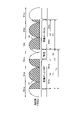
図3は、第1の実施形態の第1の設定例に係る取得時間T1及び取得間隔T2の例を示す図である。ここで例示する外乱光は、周波数100Hz、すなわち10msの変動周期で点滅を繰り返す光である。外乱光の強度は、図3に示すように波動状に変動する。 FIG. 3 is a diagram showing an example of the acquisition time T1 and the acquisition interval T2 according to the first setting example of the first embodiment. The disturbance light exemplified here is light that repeatedly blinks with a frequency of 100 Hz, that is, a fluctuation period of 10 ms. The intensity of the disturbance light fluctuates in a wave-like manner as shown in FIG.
第1の設定例においては、取得時間T1と取得間隔T2との和である合計時間Tsが外乱光の変動周期の2倍(20ms)になっている。図3は、2回の取得時間T1のそれぞれにおいて消灯画像データD1(走査光を消灯させた状態で取得した画像データ)及び点灯画像データD2(走査光を点灯させた状態で取得した画像データ)が取得されることを示している。このように、合計時間Tsを変動周期の整数倍に設定することにより、消灯画像データD1のデータレベルの積分値と点灯画像データD2のデータレベルの積分値とを略一定にすることができる。これにより、周期的に変動する外乱光による影響を正確に把握して除去することが可能となる。 In the first setting example, the total time Ts, which is the sum of the acquisition time T1 and the acquisition interval T2, is twice (20 ms) the fluctuation period of the disturbance light. FIG. 3 shows unlit image data D1 (image data acquired with the scanning light turned off) and lit image data D2 (image data acquired with the scanning light turned on) at each of the two acquisition times T1. is obtained. Thus, by setting the total time Ts to an integer multiple of the fluctuation period, the integrated value of the data level of the off image data D1 and the integrated value of the data level of the lit image data D2 can be made substantially constant. As a result, it is possible to accurately grasp and remove the influence of disturbing light that periodically fluctuates.
なお、「2倍」という数値は「整数倍」の一例であり、合計時間Tsは変動周期の2倍以外の整数倍(例えば、1倍,3倍等)であってもよい。また、図3においては、取得時間T1の開始時点Sが外乱光の消灯時点(外乱光の強度が0になる時)に同期している場合が示されているが、実施形態はこれに限られるものではない。 Note that the numerical value of "two times" is an example of "integer multiple", and the total time Ts may be an integer multiple (eg, one time, three times, etc.) other than twice the fluctuation period. Further, FIG. 3 shows a case where the start time S of the acquisition time T1 is synchronized with the time when the disturbance light is extinguished (when the intensity of the disturbance light becomes 0), but the embodiment is limited to this. It is not something that can be done.
図4は、第1の実施形態の第1の設定例において取得時間T1の開始時点Sが外乱光の点灯期間に含まれている場合の例を示す図である。このように、取得時間T1の開始時点Sが外乱光の消灯時点に同期していなくても、合計時間Tsが変動周期の整数倍に設定されていれば、消灯画像データD1のデータレベルの積分値と点灯画像データD2のデータレベルの積分値とは略一定となり、図3に示す場合と同様の効果が得られる。 FIG. 4 is a diagram showing an example in which the start time S of the acquisition time T1 is included in the disturbance light lighting period in the first setting example of the first embodiment. As described above, even if the start time S of the acquisition time T1 is not synchronized with the time when the ambient light is extinguished, if the total time Ts is set to an integral multiple of the fluctuation period, the integration of the data level of the extinguished image data D1 The value and the integrated value of the data level of the lighting image data D2 are substantially constant, and the same effect as in the case shown in FIG. 3 can be obtained.
図5は、第1の実施形態の第2の設定例に係る取得時間T1及び取得間隔T2の例を示す図である。第2の設定例においては、取得時間T1が外乱光の変動周期の2倍(20ms)となっている。このように、取得時間T1を変動周期の整数倍に設定することにより、図3に示す第1の例と同様に、消灯画像データD1のデータレベルの積分値と点灯画像データD2のデータレベルの積分値とを略一定にすることができる。 FIG. 5 is a diagram showing an example of the acquisition time T1 and the acquisition interval T2 according to the second setting example of the first embodiment. In the second setting example, the acquisition time T1 is twice (20 ms) the fluctuation period of the ambient light. In this way, by setting the acquisition time T1 to an integral multiple of the fluctuation period, the integrated value of the data level of the turned-off image data D1 and the data level of the turned-on image data D2 can be calculated as in the first example shown in FIG. can be substantially constant.
図6は、第1の実施形態の第2の設定例において取得時間T1の開始時点Sが外乱光の点灯期間に含まれている場合の例を示す図である。このように、取得時間T1の開始時点Sが外乱光の消灯時点に同期していなくても、取得時間T1が変動周期の整数倍に設定されていれば、消灯画像データD1のデータレベルの積分値と点灯画像データD2のデータレベルの積分値とは略一定となり、図5に示す場合と同様の効果が得られる。 FIG. 6 is a diagram showing an example in which the start point S of the acquisition time T1 is included in the disturbance light lighting period in the second setting example of the first embodiment. As described above, even if the start time S of the acquisition time T1 is not synchronized with the time when the ambient light is extinguished, if the acquisition time T1 is set to an integral multiple of the fluctuation period, the integration of the data level of the extinguished image data D1 The value and the integrated value of the data level of the lighting image data D2 are substantially constant, and the same effect as in the case shown in FIG. 5 can be obtained.
図7は、第1の実施形態の第3の設定例に係る取得時間T1及び取得間隔T2の例を示す図である。第3の設定例においては、取得時間T1と取得間隔T2との和である合計時間Tsが外乱光の変動周期の1周期分(10ms)に相当している。これにより、サイズ検出処理に必要となる消灯画像データD1及び点灯画像データD2の取得に要する時間(データ取得時間)を最小限(2周期分)に抑えることができる。 FIG. 7 is a diagram showing an example of acquisition time T1 and acquisition interval T2 according to a third setting example of the first embodiment. In the third setting example, the total time Ts, which is the sum of the acquisition time T1 and the acquisition interval T2, corresponds to one fluctuation period (10 ms) of the disturbance light. As a result, the time (data acquisition time) required to acquire the unlit image data D1 and the lit image data D2 required for the size detection process can be minimized (for two cycles).
図8は、第1の比較例に係る取得時間T1及び取得間隔T2の例を示す図である。本比較例に係る合計時間Tsは、外乱光の変動周期の2周期分(20ms)に相当する。この場合、データ取得時間は4周期分(40ms)となり、図7に示す場合より長くなる。 FIG. 8 is a diagram showing an example of acquisition time T1 and acquisition interval T2 according to the first comparative example. The total time Ts according to this comparative example corresponds to two fluctuation periods (20 ms) of the disturbance light. In this case, the data acquisition time is four cycles (40 ms), which is longer than the case shown in FIG.
通常、サイズ検出処理は画像読取処理の前に行われるため、本設定例のようにデータ取得時間を短縮することにより、サイズ検出処理及び画像読取処理を高速化することが可能となる。 Since the size detection process is usually performed before the image reading process, shortening the data acquisition time as in this setting example makes it possible to speed up the size detection process and the image reading process.
《2種類の変動周期に対応する場合》
以下に、外乱光の2種類の変動周期に対応する場合における取得時間及び取得間隔の設定例を第4~第6の設定例として説明する。
<<When dealing with two types of fluctuation periods>>
Setting examples of the acquisition time and the acquisition interval in the case of corresponding to two types of fluctuation periods of ambient light will be described below as fourth to sixth setting examples.
図9は、第1の実施形態の第4の設定例に係る取得時間T1及び取得間隔T2の例を第1の外乱光を基準にして示す図である。図10は、第1の実施形態の第4の設定例に係る取得時間T1及び取得間隔T2の例を第2の外乱光を基準にして示す図である。第1の外乱光は、100Hzの周波数、すなわち10msの変動周期で点滅を繰り返す光である。第2の外乱光は、120Hzの周波数、すなわち約8.3msの変動周期で点滅を繰り返す光である。 FIG. 9 is a diagram showing an example of the acquisition time T1 and the acquisition interval T2 according to the fourth setting example of the first embodiment, with reference to the first disturbance light. FIG. 10 is a diagram showing an example of the acquisition time T1 and the acquisition interval T2 according to the fourth setting example of the first embodiment, with reference to the second disturbance light. The first disturbance light is light that repeatedly blinks at a frequency of 100 Hz, that is, at a fluctuation period of 10 ms. The second disturbance light is light that repeats flickering with a frequency of 120 Hz, that is, a fluctuation period of about 8.3 ms.
第4の設定例においては、図9及び図10に示すように、取得時間T1が第1の外乱光の変動周期の2周期分(20ms)に相当し、取得時間T1と取得間隔T2との合計時間Tsが第2の外乱光の変動周期の3周期分(約25ms)に相当している。このように、2種類の外乱光の周波数(変動周期)が存在する場合には、取得時間T1を一方の変動周期の整数倍に設定し、合計時間Tsを他方の変動周期の整数倍に設定することにより、両方の外乱光の影響を低減させることができる。 In the fourth setting example, as shown in FIGS. 9 and 10, the acquisition time T1 corresponds to two cycles (20 ms) of the fluctuation cycle of the first disturbance light, and the acquisition time T1 and the acquisition interval T2 are The total time Ts corresponds to three fluctuation periods (approximately 25 ms) of the second disturbance light. Thus, when there are two types of disturbance light frequencies (fluctuation periods), the acquisition time T1 is set to an integral multiple of one fluctuation period, and the total time Ts is set to an integer multiple of the other fluctuation period. By doing so, the influence of both disturbance lights can be reduced.
なお、ここでは取得時間T1を第1の外乱光の変動周期10msに対応させ、合計時間Tsを第2の外乱光の変動周期約8.3msに対応させる例を示したが、取得時間T1を第2の外乱光の変動周期約8.3msに対応させ、合計時間Tsを第1の外乱光の変動周期10msに対応させてもよい。 Here, an example is shown in which the acquisition time T1 corresponds to the fluctuation period of the first disturbance light of 10 ms, and the total time Ts corresponds to the fluctuation period of the second disturbance light of approximately 8.3 ms. The total time Ts may correspond to the fluctuation period of about 8.3 ms of the second disturbance light and the fluctuation period of the first disturbance light of 10 ms.
図11は、第1の実施形態の第5の設定例に係る取得時間T1及び取得間隔T2の例を示す図である。第5の設定例においては、取得時間T1が第1の外乱光の変動周期の1周期分(10ms)に相当し、合計時間Tsが第2の外乱光の変動周期の3周期分(約25ms)に相当している。これにより、データ取得時間を短時間(本例では約35ms)に抑えることができる。 FIG. 11 is a diagram showing an example of acquisition time T1 and acquisition interval T2 according to the fifth setting example of the first embodiment. In the fifth setting example, the acquisition time T1 corresponds to one fluctuation period (10 ms) of the first disturbance light, and the total time Ts corresponds to three fluctuation periods (about 25 ms) of the second disturbance light. ). As a result, the data acquisition time can be reduced to a short time (approximately 35 ms in this example).
図12は、第2の比較例に係る取得時間T1及び取得間隔T2の例を示す図である。本比較例に係る取得時間T1は第1の外乱光の変動周期に2周期分(20ms)に相当し、合計時間Tsは第2の外乱光の変動周期の4周期分(約33.3ms)に相当する。この場合、データ取得時間は約53.3msとなり、図11に示す場合より長くなる。 FIG. 12 is a diagram showing an example of acquisition time T1 and acquisition interval T2 according to the second comparative example. The acquisition time T1 according to this comparative example corresponds to two cycles (20 ms) of the fluctuation period of the first disturbance light, and the total time Ts corresponds to four cycles (about 33.3 ms) of the fluctuation period of the second disturbance light. corresponds to In this case, the data acquisition time is approximately 53.3 ms, which is longer than the case shown in FIG.
このように、本設定例によれば、2種類の変動周期に対応する場合であっても、データ取得時間を短縮し、サイズ検出処理及び画像読取処理を高速化することが可能となる。 As described above, according to this setting example, it is possible to shorten the data acquisition time and speed up the size detection process and the image reading process even when two types of fluctuation cycles are supported.
図13は、第1の実施形態の第6の設定例に係る取得時間T1及び取得間隔T2の例を示す図である。第6の設定例においては、取得時間T1が第1の外乱光の変動周期の1周期分(10ms)に相当し、取得間隔T2が第2の外乱光の変動周期の1周期分(約8.3ms)以下になっている。これにより、データ取得時間を最小限(本例では約26.7ms)に抑えることができ、図11に示す場合より更に高速化を図ることができる。 FIG. 13 is a diagram showing an example of the acquisition time T1 and the acquisition interval T2 according to the sixth setting example of the first embodiment. In the sixth setting example, the acquisition time T1 corresponds to one fluctuation period (10 ms) of the first disturbance light, and the acquisition interval T2 corresponds to one fluctuation period (about 8 ms) of the second disturbance light. .3 ms) or less. As a result, the data acquisition time can be minimized (approximately 26.7 ms in this example), and the speed can be further increased compared to the case shown in FIG.
<画像データの取得順序について>
上記のように、本実施形態においては消灯画像データと点灯画像データとが取得されるが、消灯画像データを点灯画像データより先に取得することが好ましい。走査光を射出する光源13は、ON/OFFの切り換え時に状態が安定するまでの安定化時間を必要とする場合が多い。そこで、消灯画像データを点灯画像データより先に取得することにより、光源13をOFFにした後の安定化時間を待たずに消灯画像データを取得することができる。
<Regarding the acquisition order of image data>
As described above, in this embodiment, the unlit image data and the lit image data are acquired, but it is preferable to acquire the unlit image data before the lit image data. The
図14は、第1の実施形態に係る画像データの取得順序の例を示す図である。本実施形態においては、サイズ検出処理を開始させるためのトリガ(例えば、コンタクトガラス11とADF20の背景部45とのなす角度が所定の条件を満たす場合等)が検出されると、画像データ取得準備が行われ、画像データ取得準備完了後に、光源13がOFFとなっている状態で消灯画像データD1が取得される。消灯画像データD1の取得完了後、光源13がONとなり、光源ONの安定化時間の経過後、点灯画像データD2が取得される。
FIG. 14 is a diagram illustrating an example of an order of acquiring image data according to the first embodiment. In this embodiment, when a trigger for starting the size detection process (for example, when the angle between the
図15は、第3の比較例に係る画像データの取得順序の例を示す図である。本比較例においては、画像データ取得準備の完了後に光源13がONとなり、光源ONの安定化時間の経過後に点灯画像データD2が取得される。そして、点灯画像データD2の取得完了後に光源13がOFFとなり、光源OFFの安定化時間の経過後に消灯画像データD1が取得される。
FIG. 15 is a diagram illustrating an example of the order of obtaining image data according to the third comparative example. In this comparative example, the
上記のように、比較例においては、両画像データD1,D2を取得する間に光源ONの安定化時間と光源OFFの安定化時間の両方が含まれるが、本実施形態によれば、両画像データD1,D2を取得する間に光源OFFの安定化時間が含まれない。これにより、本実施形態におけるデータ取得時間は比較例におけるデータ取得時間より短くなる。 As described above, in the comparative example, both the stabilization time with the light source ON and the stabilization time with the light source OFF are included while both image data D1 and D2 are acquired. The stabilization time for turning off the light source is not included while acquiring the data D1 and D2. As a result, the data acquisition time in this embodiment is shorter than the data acquisition time in the comparative example.
<原稿サイズの検出位置>
図16は、第1の実施形態に係る第1のキャリッジ14の動きの例を示す図である。図16に示すように、サイズ検出処理の実行時(原稿21の主走査方向(X軸方向)のサイズを検出する際)に、第1のキャリッジ14を所定の開始位置Psから画像読取処理の実行時における移動方向αとは反対の移動方向βに移動させてもよい。なお、サイズ検出処理の実行時に第1のキャリッジ14を画像読取処理の実行時における移動方向αと同一の方向に移動させてもよい。
<Detection position of document size>
FIG. 16 is a diagram showing an example of movement of the
<画像形成装置の構成>
図17は、第1の実施形態に係る複写機201の構成例を示す図である。複写機201は、上記読取装置1を利用して構成される画像読取装置211を含む画像形成装置の一例である。複写機201は、画像読取装置211、給紙部212、及び画像形成部213を含む。
<Configuration of Image Forming Apparatus>
FIG. 17 is a diagram showing a configuration example of the
画像読取装置211は、上記読取装置1のセンサボード17により取得された画像データに基づいて原稿21の画像を読み取る装置である。
The
給紙部212は、サイズの異なる記録紙(記録媒体)を収納する給紙カセット221,222と、給紙カセット221,222に収納された記録紙を画像形成部213の画像形成位置まで搬送する各種ローラからなる給紙手段223とを有する。
The
画像形成部213は、露光装置231と、感光体ドラム232と、現像装置233と、転写ベルト234と、定着装置235とを有する。画像形成部213は、画像読取装置211により読み取られた原稿21の画像データに基づいて、露光装置231により感光体ドラム232を露光して感光体ドラム232に潜像を形成し、現像装置233により感光体ドラム232に異なる色のトナーを供給して現像するようになっている。そして、画像形成部213は、転写ベルト234により感光体ドラム232に現像された像を給紙部212から供給された記録紙に転写した後、定着装置235により記録紙に転写されたトナー画像のトナーを溶融して、記録紙にカラー画像を定着するようになっている。
The
以上のように、本実施形態によれば、周期的に変動する外乱光等の変動要因の影響を軽減することが可能となる。 As described above, according to the present embodiment, it is possible to reduce the influence of fluctuation factors such as periodically fluctuating disturbance light.
以下に、他の実施形態について図面を参照して説明するが、第1の実施形態と同一又は同様の作用効果を奏する箇所については同一の符号を付してその説明を省略する場合がある。 Other embodiments will be described below with reference to the drawings, but portions that have the same or similar effects as those of the first embodiment may be denoted by the same reference numerals, and descriptions thereof may be omitted.
(第2の実施形態)
一般的な外乱光である蛍光灯の光は、公共の交流電源の周波数に依存した周期で点滅するが、当該交流電源に依存しない周期で点滅する外乱光がサイズ検出処理に影響を与える可能性がある。そこで、本実施形態は、外乱光の周波数を検出し、検出された周波数に応じて取得時間及び取得間隔を設定する手段を有する。
(Second embodiment)
Fluorescent light, which is a common disturbance light, blinks at a cycle that depends on the frequency of public AC power, but disturbance light that blinks at a cycle that does not depend on the AC power may affect the size detection process. There is Therefore, this embodiment has means for detecting the frequency of ambient light and setting the acquisition time and the acquisition interval according to the detected frequency.
図18は、第2の実施形態に係る読取装置2の機能構成例を示すブロック図である。本実施形態に係る読取装置2は、外乱光の周波数(変動周期)を検出し、その検出結果に基づいて取得時間設定値及び取得間隔設定値を出力する周波数検出部302(検出手段)を有する。周波数検出部302の具体的な構成は特に限定されるべきものではないが、周波数検出部302は、例えば、読取装置2の内部又は外部に設置され外乱光の強度を電圧に変換する光電変換素子等を利用して構成され得る。
FIG. 18 is a block diagram showing a functional configuration example of the
本実施形態に係る制御部301の取得時間設定部311は、周波数検出部302から出力された取得時間設定値に基づいて取得時間を設定し、設定した取得時間を示す取得時間制御信号をセンサボード17に出力する。取得間隔設定部312は、周波数検出部302から出力された取得間隔設定値に基づいて取得間隔を設定し、設定した取得間隔を示す取得間隔制御信号をセンサボード17に出力する。センサボード17は、受信した取得時間制御信号及び取得間隔制御信号が示す取得時間及び取得間隔で画像データ(消灯画像データ及び点灯画像データ)を取得する。
The acquisition
図19は、第2の実施形態に係る周波数検出部302が出力する取得時間設定値及び取得間隔設定値の例を示す図である。ここでは、周波数40Hz及び周波数50Hzの2種類の外乱光が存在する場合を例示する。このような場合、周波数検出部302は、例えば、取得時間設定値を40Hzの周期の整数倍(1倍)である25msとする。また、周波数検出302は、合計時間が50Hzの周期の整数倍(2倍)である40msとなるように、取得間隔設定値を15msとする。なお、ここで示した取得時間設定値及び取得間隔設定値は単なる例示であり、取得時間設定値及び取得間隔設定値は、第1の実施形態で示した各種の設定例のように状況に応じて適宜設定され得るものである。
FIG. 19 is a diagram showing an example of acquisition time setting values and acquisition interval setting values output by the
また、本実施形態に係る制御部301は、図18に示すように、サイズ検出部313を有する。サイズ検出部313は、演算部124による演算結果、すなわち消灯画像データと点灯画像データとの差分を示す差分データに基づいて、原稿21の全体的なサイズ(例えばA4、B5等)を検出する処理を行う。
Further, the
本実施形態によれば、外乱光等の変動要因の周波数(変動周期)が一般的な固定値でない場合、周波数が変化する場合等であっても、変動要因の影響を効果的に除去することが可能となる。 According to this embodiment, even if the frequency (fluctuation period) of the fluctuation factor such as disturbance light is not a general fixed value, or even if the frequency changes, the influence of the fluctuation factor can be effectively removed. becomes possible.
(第3の実施形態)
図20は、第3の実施形態に係る読取装置3の機能構成例を示すブロック図である。本実施形態に係る周波数検出部302は、記憶部123に記憶された画像データに基づいて外乱光の周波数を検出する。例えば、記憶部123に記憶された画像データを1ライン毎に比較して画像データレベルの増減の周期を算出すること等により、外乱光の周波数を検出することができる。また、センサボード17は、背景部45が開けられたタイミングで(コンタクトガラス11と背景部45とのなす角度が0°から所定角度以上になったとき等に)、消灯画像データを取得することが好ましい。
(Third Embodiment)
FIG. 20 is a block diagram showing a functional configuration example of the
本実施形態によれば、周波数検出部302をソフトウェア的に構成することができ、装置の小型化、コストの削減等を図ることができる。
According to the present embodiment, the
上記実施形態に係る読取装置1~3の機能を実現するプログラムは、インストール可能な形式又は実行可能な形式のファイルでCD-ROM、フレキシブルディスク(FD)、CD-R、DVD(Digital Versatile Disk)等のコンピュータで読み取り可能な記録媒体に記録して提供するように構成してもよい。また、プログラムを、インターネット等のネットワークに接続された他のコンピュータ上に格納し、ネットワーク経由でダウンロードさせることにより提供するように構成してもよい。また、プログラムをネットワーク経由で提供又は配布するように構成してもよい。
Programs for realizing the functions of the
以上、本発明の実施形態を説明したが、上記実施形態は例として提示したものであり、発明の範囲を限定することを意図するものではない。この新規な実施形態はその他の様々な形態で実施されることが可能であり、発明の要旨を逸脱しない範囲で種々の省略、置き換え、変更、及び組み合わせを行うことができる。この実施形態及びその変形は発明の範囲及び要旨に含まれるとともに、特許請求の範囲に記載された発明とその均等の範囲に含まれる。 Although the embodiment of the present invention has been described above, the above embodiment is presented as an example and is not intended to limit the scope of the invention. This novel embodiment can be implemented in various other forms, and various omissions, replacements, changes, and combinations can be made without departing from the spirit of the invention. This embodiment and its modifications are included in the scope and gist of the invention, and are included in the scope of the invention described in the claims and its equivalents.
1~3 読取装置
11 コンタクトガラス
12 基準白板
13 光源
14 第1のキャリッジ
15 第2のキャリッジ
16 レンズ
17 センサボード
18 スキャナモータ
19 読取窓
20 ADF
21 原稿
31 第1のミラー
32 第2のミラー
33 第3のミラー
41 原稿トレイ
42 搬送ドラム
43 排紙ローラ
44 排紙トレイ
45 背景部
101,301,401 制御部
111 光源制御部
121,311 取得時間設定部
122,312 取得間隔設定部
123 記憶部
124 演算部
201 複写機(画像形成装置)
211 画像読取装置
212 給紙部
213 画像形成部
221,222 給紙カセット
223 給紙手段
231 露光装置
232 感光体ドラム
233 現像装置
234 転写ベルト
302 周波数検出部
313 サイズ検出部
D1 消灯画像データ
D2 点灯画像データ
P 開始位置
S 開始時点
T1 取得時間
T2 取得間隔
Ts 合計時間
1 to 3
21
211
Claims (11)
前記走査光の点灯及び消灯を切り換える光制御手段と、
前記被写体からの反射光を光電変換し、前記被写体の画像を示す画像データを生成する受光手段と、
前記受光手段により連続的に前記画像データを取得する時間である取得時間を設定する取得時間設定手段と、
複数回行われる前記画像データの取得の間に生じるインターバルである取得間隔を設定する取得間隔設定手段と、
前記走査光の点灯時における前記画像データと前記走査光の消灯時における前記画像データとの差分を演算する演算手段と、
を備え、
前記受光手段は、前記消灯時における前記画像データを前記点灯時における前記画像データより先に取得し、
前記取得時間、又は前記取得時間と前記取得間隔との合計時間は、変動要因の変動周期の整数倍である、
読取装置。 lighting means for irradiating a subject with scanning light;
light control means for switching on and off of the scanning light;
a light-receiving means for photoelectrically converting reflected light from the subject to generate image data representing an image of the subject ;
acquisition time setting means for setting an acquisition time, which is the time for continuously acquiring the image data by the light receiving means;
acquisition interval setting means for setting an acquisition interval, which is an interval between acquisitions of the image data performed a plurality of times;
computing means for computing a difference between the image data when the scanning light is turned on and the image data when the scanning light is turned off;
with
The light receiving means acquires the image data when the light is off before the image data when the light is on,
The acquisition time, or the total time of the acquisition time and the acquisition interval, is an integer multiple of the fluctuation period of the fluctuation factor,
reader.
請求項1に記載の読取装置。 The total time is one period of the fluctuation period,
2. A reader according to claim 1.
前記合計時間は、第2の変動周期の整数倍である、
請求項1に記載の読取装置。 The acquisition time is an integral multiple of the first fluctuation period,
The total time is an integer multiple of the second fluctuation period,
2. A reader according to claim 1.
前記合計時間は、第2の変動周期の整数倍である、
請求項1に記載の読取装置。 The acquisition time is one cycle of the first fluctuation cycle,
The total time is an integer multiple of the second fluctuation period,
2. A reader according to claim 1.
前記取得間隔は、第2の変動周期の1周期分以下である、
請求項1に記載の読取装置。 The acquisition time is one cycle of the first fluctuation cycle,
The acquisition interval is one cycle or less of the second fluctuation cycle,
2. A reader according to claim 1.
を更に備える請求項1~5のいずれか1項に記載の読取装置。 size detection means for detecting the size of the subject based on the difference calculated from the image data acquired by the light receiving means during the period for detecting the size of the subject;
The reader according to any one of claims 1 to 5 , further comprising:
を更に備え、
前記取得時間設定手段は、前記検出手段で検出された前記変動周期に基づいて前記取得時間を設定し、
前記取得間隔設定手段は、前記検出手段で検出された前記変動周期に基づいて前記取得間隔を設定する、
請求項1~6のいずれか1項に記載の読取装置。 detection means for detecting the fluctuation period;
further comprising
The acquisition time setting means sets the acquisition time based on the fluctuation period detected by the detection means ,
The acquisition interval setting means sets the acquisition interval based on the fluctuation period detected by the detection means.
The reader according to any one of claims 1-6 .
請求項7に記載の読取装置。 The detection means detects the fluctuation period based on the image data acquired by the light receiving means.
8. A reader according to claim 7 .
前記受光手段により取得された前記画像データに基づいて前記被写体の画像を読み取る手段と、
を備える画像読取装置。 a reader according to any one of claims 1 to 8 ;
means for reading an image of the subject based on the image data acquired by the light receiving means;
an image reader.
前記画像読取装置により読み取られた前記被写体の画像を記録媒体に印刷する手段と、
を備える画像形成装置。 an image reading device according to claim 9 ;
means for printing the image of the subject read by the image reading device on a recording medium;
An image forming apparatus comprising:
前記走査光の点灯及び消灯を切り換える光制御工程と、
前記被写体からの反射光を光電変換し、前記被写体の画像を示す画像データを生成する受光工程と、
前記受光工程により連続的に前記画像データを取得する時間である取得時間を設定する取得時間設定工程と、
複数回行われる前記画像データの取得の間に生じるインターバルである取得間隔を設定する取得間隔設定工程と、
前記走査光の点灯時における前記画像データと前記走査光の消灯時における前記画像データとの差分を演算する演算工程と、
を含み、
前記受光工程は、前記消灯時における前記画像データを前記点灯時における前記画像データより先に取得し、
前記取得時間、又は前記取得時間と前記取得間隔との合計時間は、変動要因の変動周期の整数倍である、
読取方法。 an illumination step of irradiating a subject with scanning light;
a light control step of switching on and off of the scanning light;
a light receiving step of photoelectrically converting reflected light from the subject to generate image data representing an image of the subject ;
an acquisition time setting step of setting an acquisition time, which is a time for continuously acquiring the image data by the light receiving step;
an acquisition interval setting step of setting an acquisition interval, which is an interval occurring between acquisitions of the image data performed a plurality of times;
a calculating step of calculating a difference between the image data when the scanning light is turned on and the image data when the scanning light is turned off;
including
In the light receiving step, the image data when the light is off is obtained before the image data when the light is on,
The acquisition time, or the total time of the acquisition time and the acquisition interval, is an integer multiple of the fluctuation period of the fluctuation factor,
reading method.
Priority Applications (2)
| Application Number | Priority Date | Filing Date | Title |
|---|---|---|---|
| JP2018193870A JP7183682B2 (en) | 2018-10-12 | 2018-10-12 | Reading device, image reading device, image forming device, and reading method |
| US16/589,258 US11089177B2 (en) | 2018-10-12 | 2019-10-01 | Reading device, image forming apparatus, and image reading method |
Applications Claiming Priority (1)
| Application Number | Priority Date | Filing Date | Title |
|---|---|---|---|
| JP2018193870A JP7183682B2 (en) | 2018-10-12 | 2018-10-12 | Reading device, image reading device, image forming device, and reading method |
Publications (2)
| Publication Number | Publication Date |
|---|---|
| JP2020061722A JP2020061722A (en) | 2020-04-16 |
| JP7183682B2 true JP7183682B2 (en) | 2022-12-06 |
Family
ID=70160701
Family Applications (1)
| Application Number | Title | Priority Date | Filing Date |
|---|---|---|---|
| JP2018193870A Active JP7183682B2 (en) | 2018-10-12 | 2018-10-12 | Reading device, image reading device, image forming device, and reading method |
Country Status (2)
| Country | Link |
|---|---|
| US (1) | US11089177B2 (en) |
| JP (1) | JP7183682B2 (en) |
Families Citing this family (9)
| Publication number | Priority date | Publication date | Assignee | Title |
|---|---|---|---|---|
| JP7287227B2 (en) | 2019-09-30 | 2023-06-06 | 株式会社リコー | Signal correction device, image reading device, image processing device, signal correction method and program |
| JP2021141467A (en) | 2020-03-05 | 2021-09-16 | 株式会社リコー | Reading device, image processing device, and feature amount detection method |
| US11457116B2 (en) | 2020-06-17 | 2022-09-27 | Ricoh Company, Ltd. | Image processing apparatus and image reading method |
| JP2022006850A (en) | 2020-06-25 | 2022-01-13 | 株式会社リコー | Solid-state image sensor, reader, image processing device and control method |
| JP2022018303A (en) | 2020-07-15 | 2022-01-27 | 株式会社リコー | Information processing system, image forming apparatus, and method |
| JP2022059526A (en) | 2020-10-01 | 2022-04-13 | 株式会社リコー | Reading device, image forming apparatus, and state detection method |
| JP2022059534A (en) | 2020-10-01 | 2022-04-13 | 株式会社リコー | Reading device, image forming apparatus, and correction method |
| JP2022110367A (en) | 2021-01-18 | 2022-07-29 | 株式会社リコー | Fraud confirmation assist device and fraud confirmation method |
| JP2023130132A (en) | 2022-03-07 | 2023-09-20 | 株式会社リコー | Document placement detection device, image reading device, image forming apparatus, method, and program |
Citations (3)
| Publication number | Priority date | Publication date | Assignee | Title |
|---|---|---|---|---|
| JP2001066254A (en) | 1999-08-26 | 2001-03-16 | Fuji Photo Film Co Ltd | Photometric method and apparatus |
| JP2009188760A (en) | 2008-02-06 | 2009-08-20 | Panasonic Electric Works Co Ltd | Imaging device |
| JP2011217339A (en) | 2009-08-19 | 2011-10-27 | Canon Electronics Inc | Image reading apparatus, method of controlling the same, and program |
Family Cites Families (58)
| Publication number | Priority date | Publication date | Assignee | Title |
|---|---|---|---|---|
| JPH07298002A (en) * | 1994-04-26 | 1995-11-10 | Canon Inc | Image pickup device |
| JP3087684B2 (en) | 1997-06-02 | 2000-09-11 | 日本電気株式会社 | Image reading device |
| US7502054B2 (en) * | 2004-12-20 | 2009-03-10 | Pixim, Inc. | Automatic detection of fluorescent flicker in video images |
| JP4565567B2 (en) | 2006-02-07 | 2010-10-20 | 株式会社リコー | Analog signal buffer, analog signal processing system, image reading apparatus, and image forming apparatus |
| JP4699417B2 (en) | 2007-04-16 | 2011-06-08 | 株式会社リコー | Analog processing circuit, analog integrated circuit device, image reading device, and image forming device |
| JP5444795B2 (en) | 2008-07-29 | 2014-03-19 | 株式会社リコー | Image reading apparatus, image forming apparatus, amplitude adjusting method, and computer program |
| JP5206423B2 (en) | 2009-01-07 | 2013-06-12 | 株式会社リコー | Image reading apparatus, image forming apparatus, and sample / hold control method |
| JP5326911B2 (en) | 2009-07-30 | 2013-10-30 | 株式会社リコー | Spread spectrum clock generator, circuit device, image reading device, image forming device, and spread spectrum clock generation method |
| JP5454019B2 (en) | 2009-09-02 | 2014-03-26 | 株式会社リコー | Photoelectric conversion element, sensor control circuit, image reading apparatus, and image forming apparatus |
| JP5476876B2 (en) | 2009-09-11 | 2014-04-23 | 株式会社リコー | Sensor driving circuit, driver device, image reading device, and image forming device |
| JP2011222360A (en) | 2010-04-12 | 2011-11-04 | Ricoh Co Ltd | Light source driving device, image processing device, image reading device, and image forming device |
| JP5830837B2 (en) | 2010-09-01 | 2015-12-09 | 株式会社リコー | Image reading apparatus and image forming apparatus |
| JP2012119868A (en) | 2010-11-30 | 2012-06-21 | Kyocera Document Solutions Inc | Image reading device, and image forming apparatus |
| JP5724463B2 (en) | 2011-03-03 | 2015-05-27 | 株式会社リコー | Signal processing circuit, image reading apparatus, and image forming apparatus |
| JP5842350B2 (en) | 2011-03-18 | 2016-01-13 | 株式会社リコー | LIGHT SOURCE CONTROL DEVICE, LIGHT SOURCE CONTROL METHOD, IMAGE READING DEVICE, AND IMAGE FORMING DEVICE |
| JP6226508B2 (en) | 2011-09-13 | 2017-11-08 | 株式会社リコー | Image reading apparatus, image forming apparatus, and image reading method |
| JP5651566B2 (en) | 2011-10-07 | 2015-01-14 | 京セラドキュメントソリューションズ株式会社 | Image reading apparatus and image forming apparatus |
| JP5862293B2 (en) | 2011-12-28 | 2016-02-16 | 株式会社リコー | Image reading apparatus, automatic document feeder, and image forming apparatus |
| JP6051654B2 (en) | 2012-07-25 | 2016-12-27 | 株式会社リコー | Image reading apparatus and image forming apparatus |
| JP6060557B2 (en) | 2012-08-13 | 2017-01-18 | 株式会社リコー | Image processing device |
| JP6146015B2 (en) | 2013-01-18 | 2017-06-14 | 株式会社リコー | Photoelectric conversion element, image reading apparatus, and image forming apparatus |
| JP6127536B2 (en) | 2013-01-24 | 2017-05-17 | 株式会社リコー | Image reading apparatus, image forming apparatus, and image reading method |
| JP6149408B2 (en) | 2013-01-29 | 2017-06-21 | 株式会社リコー | Solid-state imaging device, image reading apparatus, and image forming apparatus |
| JP6205885B2 (en) | 2013-06-18 | 2017-10-04 | 株式会社リコー | Photoelectric conversion element, image reading apparatus, image forming apparatus, and image reading method |
| JP6268765B2 (en) | 2013-06-20 | 2018-01-31 | 株式会社リコー | Image forming apparatus, image forming method, and program |
| JP6383143B2 (en) | 2013-10-08 | 2018-08-29 | 株式会社リコー | Imaging device, image reading apparatus, image forming apparatus, and imaging method |
| JP6287058B2 (en) | 2013-10-24 | 2018-03-07 | 株式会社リコー | Photoelectric conversion element for reduction optical system, image reading apparatus, image forming apparatus, and image reading method |
| JP2015131483A (en) | 2013-12-09 | 2015-07-23 | 株式会社リコー | Image forming apparatus, calibration method, and drying determination method |
| JP6225682B2 (en) | 2013-12-11 | 2017-11-08 | 株式会社リコー | Image sensor, image reading apparatus, and image forming apparatus |
| JP6281304B2 (en) | 2014-02-04 | 2018-02-21 | 株式会社リコー | Image sensor, image reading apparatus, and image forming apparatus |
| JP2015165626A (en) | 2014-03-03 | 2015-09-17 | 株式会社リコー | Document reading device and image forming apparatus |
| JP6519997B2 (en) | 2014-07-04 | 2019-05-29 | 株式会社リコー | PHOTOELECTRIC CONVERSION ELEMENT, IMAGE READER, AND IMAGE FORMING APPARATUS |
| JP6451104B2 (en) | 2014-07-04 | 2019-01-16 | 株式会社リコー | Photoelectric conversion element, image reading apparatus, image forming apparatus, and signal control method |
| JP6549366B2 (en) | 2014-09-19 | 2019-07-24 | 株式会社リコー | PHOTOELECTRIC CONVERSION ELEMENT, IMAGE READER, AND IMAGE FORMING APPARATUS |
| JP6612492B2 (en) | 2014-10-16 | 2019-11-27 | 株式会社リコー | Photoelectric conversion element, image reading apparatus, and image forming apparatus |
| JP6519142B2 (en) | 2014-10-28 | 2019-05-29 | 株式会社リコー | Processing apparatus, image reading apparatus, and image forming apparatus |
| JP6432332B2 (en) | 2014-12-15 | 2018-12-05 | 株式会社リコー | Photoelectric conversion element, image reading apparatus, and image forming apparatus |
| JP6451344B2 (en) | 2015-01-23 | 2019-01-16 | 株式会社リコー | Image reading apparatus, image processing apparatus, and image reading method |
| JP6569302B2 (en) | 2015-05-27 | 2019-09-04 | 株式会社リコー | Image forming apparatus, method for adjusting image forming apparatus, and program |
| US10158767B2 (en) | 2015-06-09 | 2018-12-18 | Ricoh Company, Ltd. | Image capturing apparatus, image forming apparatus, distance measuring method, and computer-readable recording medium |
| JP6544070B2 (en) | 2015-06-16 | 2019-07-17 | 株式会社リコー | PHOTOELECTRIC CONVERSION ELEMENT, IMAGE READER, AND IMAGE FORMING APPARATUS |
| US9973659B2 (en) | 2015-07-13 | 2018-05-15 | Ricoh Company, Ltd. | Imaging element, image reading device, image forming apparatus, and imaging method |
| JP6536238B2 (en) | 2015-07-13 | 2019-07-03 | 株式会社リコー | Image reading apparatus and image forming apparatus |
| JP6630511B2 (en) * | 2015-07-31 | 2020-01-15 | 理想科学工業株式会社 | Image reading device |
| JP6790752B2 (en) | 2015-11-20 | 2020-11-25 | 株式会社リコー | Image reader, image forming device and image reading method |
| JP6682832B2 (en) | 2015-12-03 | 2020-04-15 | 株式会社リコー | Photoelectric conversion element, image reading device, image forming device, and image reading method |
| JP6668728B2 (en) | 2015-12-14 | 2020-03-18 | 株式会社リコー | Photoelectric conversion element, image reading device, and image forming device |
| JP2017126833A (en) | 2016-01-12 | 2017-07-20 | 株式会社リコー | Photoelectric conversion element, image reading apparatus, image forming apparatus, and image reading method |
| US10362994B2 (en) * | 2016-02-29 | 2019-07-30 | Texas Instruments Incorporated | Bio-sensing device with ambient light cancellation |
| JP6699305B2 (en) | 2016-04-07 | 2020-05-27 | 株式会社リコー | Signal processing device, photoelectric conversion element, image reading device, image forming device, and signal processing method |
| US10182177B2 (en) | 2016-04-15 | 2019-01-15 | Ricoh Company, Ltd. | Signal processing device, image scanning device, image forming apparatus, and method of controlling the same |
| JP6822096B2 (en) | 2016-11-24 | 2021-01-27 | 株式会社リコー | Photoelectric conversion device, photoelectric conversion method and image forming device |
| JP6880709B2 (en) | 2016-12-20 | 2021-06-02 | 株式会社リコー | Photoelectric conversion device, photoelectric conversion method and image forming device |
| US10542184B2 (en) | 2017-01-25 | 2020-01-21 | Ricoh Company, Ltd. | Photoelectric conversion device, defective pixel determining method, image forming apparatus, and recording medium |
| JP6946983B2 (en) | 2017-11-30 | 2021-10-13 | 株式会社リコー | Position detection device, image reader, image forming device, program and position detection method |
| CN109862201A (en) | 2017-11-30 | 2019-06-07 | 株式会社理光 | Reading device, image forming apparatus, reference pattern read method |
| US10931845B2 (en) | 2017-11-30 | 2021-02-23 | Ricoh Company, Ltd. | Reading device, image forming apparatus, correction value calculating method, and storage medium storing program code |
| JP7056176B2 (en) | 2018-01-26 | 2022-04-19 | 株式会社リコー | Position detection device, image forming device, and position detection method |
-
2018
- 2018-10-12 JP JP2018193870A patent/JP7183682B2/en active Active
-
2019
- 2019-10-01 US US16/589,258 patent/US11089177B2/en active Active
Patent Citations (3)
| Publication number | Priority date | Publication date | Assignee | Title |
|---|---|---|---|---|
| JP2001066254A (en) | 1999-08-26 | 2001-03-16 | Fuji Photo Film Co Ltd | Photometric method and apparatus |
| JP2009188760A (en) | 2008-02-06 | 2009-08-20 | Panasonic Electric Works Co Ltd | Imaging device |
| JP2011217339A (en) | 2009-08-19 | 2011-10-27 | Canon Electronics Inc | Image reading apparatus, method of controlling the same, and program |
Also Published As
| Publication number | Publication date |
|---|---|
| JP2020061722A (en) | 2020-04-16 |
| US20200120228A1 (en) | 2020-04-16 |
| US11089177B2 (en) | 2021-08-10 |
Similar Documents
| Publication | Publication Date | Title |
|---|---|---|
| JP7183682B2 (en) | Reading device, image reading device, image forming device, and reading method | |
| JP7131287B2 (en) | Document size detection device, image reading device, image forming device, and document size detection method | |
| US20050243384A1 (en) | Image scanner for use in image forming apparatus | |
| JP2012142948A (en) | Image reader and control method of the same | |
| JP2020061672A (en) | Document size detection device, image reading device, image forming apparatus, and document size detection method | |
| JPH0253082A (en) | Copying machine | |
| US11381702B2 (en) | Image reading device, image reading method, and computer-readable medium | |
| JP5533230B2 (en) | Image reading apparatus and image forming apparatus | |
| JP6512285B2 (en) | Image reading apparatus, image processing apparatus, image reading method | |
| JP2005266690A (en) | Image forming apparatus | |
| JP2010068228A (en) | Image reading apparatus, and image forming apparatus | |
| JP6130756B2 (en) | Image reading apparatus and image forming apparatus having the same | |
| KR101846935B1 (en) | Image reading apparatus and controlling method thereof | |
| JP4065512B2 (en) | Data processing device | |
| JP2008028662A (en) | Image reader and image forming apparatus | |
| EP1150487A2 (en) | Image reading apparatus and image forming apparatus | |
| JP2017011418A (en) | Photoelectric conversion element, image reading device, image forming apparatus, and control method of photoelectric conversion element | |
| JP6369371B2 (en) | Image reading apparatus, image processing apparatus, and image reading apparatus control method | |
| JP6369372B2 (en) | Image reading apparatus, image processing apparatus, and image reading apparatus control method | |
| JP6012370B2 (en) | Image reading apparatus and image forming apparatus | |
| JP2014027536A (en) | Image reader and image forming apparatus | |
| JP2018129737A (en) | Scanner for turning on light source during closing of pressure plate and detection program of sheet size by scanner | |
| JP2006211124A (en) | Image reading apparatus and image forming apparatus | |
| JP2010252333A (en) | Image reading apparatus, method of controlling the same, and image forming apparatus | |
| JP2007013907A (en) | Image reading apparatus, and image forming apparatus |
Legal Events
| Date | Code | Title | Description |
|---|---|---|---|
| A621 | Written request for application examination |
Free format text: JAPANESE INTERMEDIATE CODE: A621 Effective date: 20210726 |
|
| RD04 | Notification of resignation of power of attorney |
Free format text: JAPANESE INTERMEDIATE CODE: A7424 Effective date: 20220204 |
|
| A977 | Report on retrieval |
Free format text: JAPANESE INTERMEDIATE CODE: A971007 Effective date: 20220413 |
|
| A131 | Notification of reasons for refusal |
Free format text: JAPANESE INTERMEDIATE CODE: A131 Effective date: 20220524 |
|
| A521 | Request for written amendment filed |
Free format text: JAPANESE INTERMEDIATE CODE: A523 Effective date: 20220628 |
|
| TRDD | Decision of grant or rejection written | ||
| A01 | Written decision to grant a patent or to grant a registration (utility model) |
Free format text: JAPANESE INTERMEDIATE CODE: A01 Effective date: 20221025 |
|
| A61 | First payment of annual fees (during grant procedure) |
Free format text: JAPANESE INTERMEDIATE CODE: A61 Effective date: 20221107 |
|
| R151 | Written notification of patent or utility model registration |
Ref document number: 7183682 Country of ref document: JP Free format text: JAPANESE INTERMEDIATE CODE: R151 |