JP2015165626A - Document reading device and image forming apparatus - Google Patents
Document reading device and image forming apparatus Download PDFInfo
- Publication number
- JP2015165626A JP2015165626A JP2014040199A JP2014040199A JP2015165626A JP 2015165626 A JP2015165626 A JP 2015165626A JP 2014040199 A JP2014040199 A JP 2014040199A JP 2014040199 A JP2014040199 A JP 2014040199A JP 2015165626 A JP2015165626 A JP 2015165626A
- Authority
- JP
- Japan
- Prior art keywords
- document
- length
- scanning direction
- image
- light
- Prior art date
- Legal status (The legal status is an assumption and is not a legal conclusion. Google has not performed a legal analysis and makes no representation as to the accuracy of the status listed.)
- Pending
Links
Images


Classifications
-
- H—ELECTRICITY
- H04—ELECTRIC COMMUNICATION TECHNIQUE
- H04N—PICTORIAL COMMUNICATION, e.g. TELEVISION
- H04N1/00—Scanning, transmission or reproduction of documents or the like, e.g. facsimile transmission; Details thereof
- H04N1/00681—Detecting the presence, position or size of a sheet or correcting its position before scanning
- H04N1/00684—Object of the detection
- H04N1/00708—Size or dimensions
- H04N1/00713—Length
-
- H—ELECTRICITY
- H04—ELECTRIC COMMUNICATION TECHNIQUE
- H04N—PICTORIAL COMMUNICATION, e.g. TELEVISION
- H04N1/00—Scanning, transmission or reproduction of documents or the like, e.g. facsimile transmission; Details thereof
- H04N1/00681—Detecting the presence, position or size of a sheet or correcting its position before scanning
- H04N1/00729—Detection means
- H04N1/00734—Optical detectors
- H04N1/00737—Optical detectors using the scanning elements as detectors
-
- H—ELECTRICITY
- H04—ELECTRIC COMMUNICATION TECHNIQUE
- H04N—PICTORIAL COMMUNICATION, e.g. TELEVISION
- H04N1/00—Scanning, transmission or reproduction of documents or the like, e.g. facsimile transmission; Details thereof
- H04N1/00681—Detecting the presence, position or size of a sheet or correcting its position before scanning
- H04N1/00742—Detection methods
- H04N1/00755—Detecting an interruption of light
-
- H—ELECTRICITY
- H04—ELECTRIC COMMUNICATION TECHNIQUE
- H04N—PICTORIAL COMMUNICATION, e.g. TELEVISION
- H04N1/00—Scanning, transmission or reproduction of documents or the like, e.g. facsimile transmission; Details thereof
- H04N1/04—Scanning arrangements, i.e. arrangements for the displacement of active reading or reproducing elements relative to the original or reproducing medium, or vice versa
- H04N1/10—Scanning arrangements, i.e. arrangements for the displacement of active reading or reproducing elements relative to the original or reproducing medium, or vice versa using flat picture-bearing surfaces
- H04N1/1013—Scanning arrangements, i.e. arrangements for the displacement of active reading or reproducing elements relative to the original or reproducing medium, or vice versa using flat picture-bearing surfaces with sub-scanning by translatory movement of at least a part of the main-scanning components
- H04N1/1039—Movement of the main scanning components
- H04N1/1043—Movement of the main scanning components of a sensor array
-
- H—ELECTRICITY
- H04—ELECTRIC COMMUNICATION TECHNIQUE
- H04N—PICTORIAL COMMUNICATION, e.g. TELEVISION
- H04N1/00—Scanning, transmission or reproduction of documents or the like, e.g. facsimile transmission; Details thereof
- H04N1/04—Scanning arrangements, i.e. arrangements for the displacement of active reading or reproducing elements relative to the original or reproducing medium, or vice versa
- H04N1/10—Scanning arrangements, i.e. arrangements for the displacement of active reading or reproducing elements relative to the original or reproducing medium, or vice versa using flat picture-bearing surfaces
- H04N1/1061—Details relating to flat picture-bearing surfaces, e.g. transparent platen
-
- H—ELECTRICITY
- H04—ELECTRIC COMMUNICATION TECHNIQUE
- H04N—PICTORIAL COMMUNICATION, e.g. TELEVISION
- H04N2201/00—Indexing scheme relating to scanning, transmission or reproduction of documents or the like, and to details thereof
- H04N2201/0077—Types of the still picture apparatus
- H04N2201/0081—Image reader
Abstract
Description
本発明は、光源に設けられた複数の分割光源から発した光を原稿台上の原稿に向けて照射して原稿面で得られた反射光を画像センサーで受光して原稿の画像を読み取る原稿読取装置、及びこれを搭載した画像形成装置に関するものである。 The present invention relates to a document that reads an image of a document by irradiating light emitted from a plurality of divided light sources provided on the light source toward the document on the document table and receiving reflected light obtained on the document surface by an image sensor. The present invention relates to a reading device and an image forming apparatus equipped with the reading device.
従来、この種の原稿読取装置としては、特許文献1に記載のものが知られている。この原稿読取装置は、原稿台ガラスに対して開閉動作可能な原稿押さえ手段たる原稿圧板や、原稿台ガラスの表面に沿って主走査方向に並べられた複数のLED素子を具備するLEDアレイを搭載した光学台などを備えている。この光学台は、原稿台ガラスの上に載置された原稿の画像を光走査するために、原稿台ガラスの表面に沿った方向であり且つ主走査方向に直交する方向である副走査方向に移動できるようになっている。また、原稿圧板は、操作者によって原稿台ガラスに対して閉じられることで、原稿台ガラス上の原稿を原稿台ガラスに向けて押さえ付ける。この状態で操作者によって読取開始命令がなされると、原稿読取装置は、移動照射部たる光学台の複数のLED素子から発した光をそれぞれ原稿に向けて照射して原稿面での反射光を得ながら、光学台を副走査方向に移動させる。そして、得られた反射光を画像センサーとしてのCCDに受光させて原稿の画像を読み取らせる。
Conventionally, as this type of document reading apparatus, the one described in
この原稿読取装置の制御部は、このようにして原稿の画像を読み取るのに先立って、原稿台ガラス上の原稿の主走査方向における長さを特定するための長さ特定処理を実施する。この長さ特定処理のために、原稿読取装置は、原稿圧板の近傍に、原稿圧板の開閉動作を検知する開閉センサーを具備している。操作者が原稿台ガラスの上に原稿を置くために原稿圧板を開くと、その開動作が開閉センサーによって検知される。原稿読取装置の制御部は、原稿圧板の開動作が検知されると、光学台を副走査方向における所定の待機位置から原稿の先端部に対向する原稿サイズ検知位置まで移動させる。その後、開閉センサーによって原稿圧板の閉動作の開始が検知されると、次のような長さ特定処理を実施する。即ち、LEDアレイに具備される複数のLED素子のうち、原稿の主走査方向における長さの特定に必要な一部のLED素子だけを点灯させ、その点灯によって得られた反射光をCCDで受光する。そして、CCDの主走査方向の受光領域におけるそれぞれのLED素子に対向する領域の受光量に基づいて、点灯させたLED素子についてそれぞれその対向位置に原稿が存在しているか否かを判定し、判定結果に基づいて原稿の主走査方向の長さを特定する。 Prior to reading the image of the document in this manner, the control unit of the document reading apparatus performs a length specifying process for specifying the length of the document on the document table glass in the main scanning direction. For this length specifying process, the document reading apparatus includes an open / close sensor that detects an open / close operation of the document pressure plate in the vicinity of the document pressure plate. When the operator opens the document pressure plate to place the document on the platen glass, the opening operation is detected by the open / close sensor. When the opening operation of the document pressure plate is detected, the control unit of the document reading apparatus moves the optical bench from a predetermined standby position in the sub-scanning direction to a document size detection position facing the leading edge of the document. Thereafter, when the opening / closing sensor detects the start of the closing operation of the document pressure plate, the following length specifying process is performed. That is, only a part of the LED elements necessary for specifying the length in the main scanning direction of the original among the plurality of LED elements included in the LED array are turned on, and the reflected light obtained by the lighting is received by the CCD. To do. Then, based on the amount of light received in the area facing each LED element in the light receiving area in the main scanning direction of the CCD, it is determined whether or not a document exists at the facing position for each of the LED elements that are lit. Based on the result, the length of the document in the main scanning direction is specified.
特許文献1では、原稿読取装置のかかる構成により、長さ特定処理の実施時にLED光をユーザーの目に入れてしまうことによる不快感を軽減することができるとしている。 Japanese Patent Application Laid-Open No. 2004-151867 states that this configuration of the document reading apparatus can reduce discomfort caused by the LED light entering the eyes of the user when the length specifying process is performed.
不快感を軽減できる理由につき、特許文献1においては具体的な説明がないが、次の通りであると考えられる。即ち、操作者が原稿台ガラスの上に原稿を置いて原稿圧板を閉じ始めると、原稿読取装置の制御部が長さ特定処理を開始してLED素子を点灯させ始める。その後、原稿圧板が完全に閉じられると、原稿の存在しない領域であっても、原稿を押さえている原稿圧板の表面がLED光を良好に反射させることから、その領域に原稿が存在しているものと誤検知されてしまう。このため、長さ特定処理については、原稿圧板が閉じられ始めてから、完全に閉じられる前の所定の閉じ角度になるまでの時間内に完了する必要がある。かかる時間では、原稿圧板が完全に閉じられていないことから、LED光が原稿台ガラスと原稿圧板との間から漏れてユーザーの目に入ってしまい易くなる。特許文献1に記載の原稿読取装置においては、LEDアレイに具備される全てのLED素子のうち、原稿のサイズの特定に必要な一部のLEDアレイだけを点灯させることで、全てのLED素子を点灯させる場合に比べて光量を少なくする。これにより、原稿台ガラスと原稿圧板との間から同時に漏れてしまう光の量を低減して、ユーザーの不快感を低減することができるものと考えられる。
Although there is no specific explanation in Japanese Patent Application Laid-Open No. 2004-151867 regarding the reason why the discomfort can be reduced, it is considered as follows. That is, when the operator places an original on the platen glass and starts closing the original platen, the control unit of the original reading apparatus starts the length specifying process and starts to light the LED element. After that, when the document pressure plate is completely closed, even in a region where the document is not present, the surface of the document pressure plate that holds the document reflects the LED light well, so that the document exists in that region. It will be falsely detected as a thing. For this reason, the length specifying process needs to be completed within a time from when the document pressure plate starts to be closed until a predetermined closing angle is reached before it is completely closed. In such a time, since the document pressure plate is not completely closed, the LED light easily leaks between the document table glass and the document pressure plate and enters the user's eyes. In the document reading device described in
ところが、この原稿読取装置では、原稿の副走査方向における上流側端部(以下、先端部という)にベタ画像が形成されている場合に、原稿の主走査方向の長さを誤検知してしまうおそれがある。具体的には、原稿サイズ検知位置にある光学台は、原稿の先端部に対向している。一般的な原稿の場合には、先端部に余白が設けられていることが多いが、余白が設けられていない原稿も存在する。原稿の先端部に比較的大きなベタ画像が形成されていると、原稿のベタ画像の形成領域ではベタ画像によって光の反射が阻害されることから、原稿の無垢の表面に比べて光の反射量が大幅に少なくなる。すると、原稿の主走査方向におけるベタ画像の形成領域が原稿の存在しない領域として誤検知され、これによって原稿の長さが誤検知されてしまうのである。 However, in this document reading apparatus, the length of the document in the main scanning direction is erroneously detected when a solid image is formed at the upstream end (hereinafter referred to as the leading edge) in the sub-scanning direction of the document. There is a fear. Specifically, the optical bench at the document size detection position faces the leading edge of the document. In the case of a general document, a margin is often provided at the leading edge, but there is also a document without a margin. If a relatively large solid image is formed at the leading edge of the document, the reflection of light is blocked by the solid image in the solid image formation area of the document. Is greatly reduced. Then, the solid image formation area in the main scanning direction of the original is erroneously detected as an area where the original does not exist, and thus the length of the original is erroneously detected.
本発明は、以上の背景に鑑みてなされたものであり、その目的とするところは、次のような原稿読取装置や画像形成装置を提供することである。即ち、ユーザーの不快感を軽減しつつ、先端部にベタ画像が形成されている原稿の長さの誤検知を抑えることができる原稿読取装置等である。 The present invention has been made in view of the above background, and an object thereof is to provide the following document reading apparatus and image forming apparatus. That is, it is a document reading device or the like that can reduce erroneous detection of the length of a document on which a solid image is formed at the leading end while reducing user discomfort.
上記目的を達成するために、本発明は、原稿を載置する原稿台と、前記原稿台の表面に沿った主走査方向に並ぶ複数の分割光源を具備する光源のそれぞれの分割光源から発した光を前記原稿台上の原稿に向けて照射して原稿面での反射光を得ながら、前記表面に沿いつつ主走査方向に直交する方向である副走査方向に移動する移動照射手段と、前記反射光を受光して原稿の画像を読み取る画像センサーと、前記移動照射手段を前記原稿台上の原稿に対向させた状態で、複数の前記分割光源における一部を点灯させて得られる前記画像センサーによる受光結果に基づいて前記原稿の主走査方向の長さを特定する長さ特定処理を実施する制御手段とを有する原稿読取装置において、前記長さ特定処理にて、前記移動照射手段を副走査方向に移動させながら、全ての前記分割光源のうち、原稿の主走査方向における長さの特定に必要な前記分割光源だけを、同時又は時間差で点灯させ、点灯中の前記分割光源についてそれぞれ前記画像センサーによる受光結果を取得する点灯受光処理を実施した後、それぞれの受光結果に基づいて前記長さを特定する特定処理を実施するように、前記制御手段を構成したことを特徴とするものである。 In order to achieve the above-described object, the present invention originates from each divided light source of a document table on which a document is placed and a plurality of divided light sources arranged in the main scanning direction along the surface of the document table. Moving irradiation means for moving light in a sub-scanning direction that is perpendicular to the main scanning direction along the surface while irradiating light on the document on the document table to obtain reflected light on the document surface; An image sensor that receives reflected light and reads an image of a document, and the image sensor that is obtained by lighting a part of the plurality of divided light sources in a state where the moving irradiation unit faces the document on the document table And a control unit that performs a length specifying process for specifying the length of the original in the main scanning direction based on the light reception result by the sub-scanning of the moving irradiation unit in the length specifying process. Moved in the direction However, among all the divided light sources, only the divided light sources necessary for specifying the length of the document in the main scanning direction are turned on simultaneously or with a time difference, and the light reception results by the image sensor for the lighted divided light sources, respectively. After the lighting light receiving process for acquiring the light, the control means is configured to execute a specific process for specifying the length based on each light reception result.
本発明によれば、ユーザーの不快感を軽減しつつ、先端部にベタ画像が形成されている原稿の長さの誤検知を抑えることができるという優れた効果がある。 According to the present invention, there is an excellent effect that it is possible to suppress erroneous detection of the length of a document on which a solid image is formed at the leading end while reducing user discomfort.
以下、本発明を、電子写真方式の複写機(以下、単に複写機という)に適用した実施形態について説明する。
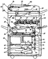
まず、実施形態に係る複写機の基本的な構成について説明する。図1は、実施形態に係る複写機を示す斜視図である。この複写機は、画像形成手段としての画像形成部1と、シート供給装置40と、画像読取ユニット50とを備えている。画像読取装置としての画像読取ユニット50は、画像形成部1の上に固定された原稿読取装置としてのスキャナ150と、これに支持されるシート搬送装置としての原稿自動搬送装置(以下、ADFという)51とを有している。
Hereinafter, an embodiment in which the present invention is applied to an electrophotographic copying machine (hereinafter simply referred to as a copying machine) will be described.
First, a basic configuration of the copying machine according to the embodiment will be described. FIG. 1 is a perspective view illustrating a copying machine according to an embodiment. The copying machine includes an
図2は、実施形態に係る複写機を示す概略構成図である。同図において、画像形成部1のシート供給装置40は、ペーパーバンク41内に多段に配設された2つの給紙カセット42、給紙カセットから記録シートを送り出す送出ローラ43、送り出された記録シートを1枚ずつに分離する分離ローラ45等を有している。また、画像形成部1の搬送路としての給紙路37に対して、シート部材としての記録シートを搬送する複数の搬送ローラ対46等も有している。
FIG. 2 is a schematic configuration diagram illustrating the copying machine according to the embodiment. In the figure, a
給紙カセット42は、複数の記録シートを重ねたシート束の状態で内部に収容している。そして、一番上の記録シートに対して送出ローラ43を押し当てている。送出ローラ43が回転すると、シート束の一番上の記録シートが給紙カセット42から送り出される。
The
給紙カセット42の付近では、搬送ローラ対46の第1搬送ローラと、これの側方(図2中右側方)に配設された第2搬送ローラとが互いに当接して搬送ニップを形成している。また、第1搬送ローラの下方には、分離ローラ45が配設されており、第1搬送ローラに対して下方から当接して分離搬送ニップを形成している。
In the vicinity of the
送出ローラ43の回転駆動によって給紙カセット42から送り出された記録シートは、搬送ローラ対46の第1搬送ローラと、これの下方に配設された分離ローラ45との当接による分離搬送ニップに進入する。この分離搬送ニップでは、記録シートの上面に当接する第1搬送ローラが図中反時計回り方向に回転駆動しながら、記録シートに対して給紙カセット42側から給送路44側に向かう搬送力を付与する。これに対し、記録シートの下面に当接する分離ローラ45が図中反時計回り方向に回転駆動しながら、記録シートに対して給送路44側から給紙カセット42側に向かう搬送力を付与して、記録シートを給紙カセット42に戻そうとする。
The recording sheet sent out from the
給紙カセット42から記録シートが1枚だけの状態で送り出された場合、分離搬送ニップにおいて、第1搬送ローラと分離ローラ45とが記録シートに対して互いに逆方向に向かう搬送力を付与する。これにより、分離ローラ45の駆動伝達系に所定の閾値を超える負荷がかかる。すると、その駆動伝達系内に配設されたトルクリミッターが作動して、図示しないDCブラシレスモータからの駆動力の分離ローラ45に対する伝達を切る。すると、分離ローラ45が第1搬送ローラによって搬送される記録シートに連れ回るようになって、記録シートが分離搬送ニップから給送路44に向けて排出される。
When only one recording sheet is sent out from the
一方、給紙カセット42から記録シートが複数枚重なった状態で送り出された場合、分離搬送ニップにおいて、第1搬送ローラが一番上の記録シートに対して給紙カセット42側から給送路44側に向かう搬送力を付与する。そして、一番上の記録シートを分離搬送ニップから給送路44側に向けて送り出す。これに対し、分離ローラが下側に位置している記録シートに対して給送路44側から給紙カセット側に向かう搬送力を付与して、下側の記録シートを分離搬送ニップ内から給紙カセット42側に逆戻りさせる。これにより、分離搬送ニップでは、一番上の記録シートが他の記録シートから分離されて1枚の状態で給送路44に送り出される。
On the other hand, when a plurality of recording sheets are fed out from the
給送路44に進入した記録シートは、搬送ローラ対46の搬送ニップに進入して、鉛直方向下方側から上方側に向かう搬送力を付与される。これにより、給送路44内では、記録シートが画像形成部1の給紙路37に向けて搬送される。
The recording sheet that has entered the
画像形成手段としての画像形成部1は、光書込装置2、黒,イエロー,マゼンタ,シアン(K,Y,M,C)のトナー像を形成する4つの作像ユニット3K,3Y,3M,3C、転写ユニット24等を備えている。また、紙搬送ユニット28、レジストローラ対33、定着装置34、スイッチバック装置36、給紙路37等も備えている。そして、光書込装置2内に配設された図示しないレーザーダイオードやLED等の光源を駆動して、ドラム状の4つの感光体4K,4Y,4M,4Cに向けてレーザー光Lを照射する。この照射により、感光体4K,4Y,4M,4Cの表面には静電潜像が形成され、この潜像は所定の現像プロセスを経由してトナー像に現像される。
An
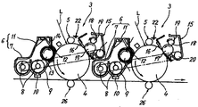
図3は、画像形成部1の内部構成の一部を拡大して示す部分構成図である。また、図4は、4つの作像ユニット3K,3Y,3M,3Cからなるタンデム部の一部を示す部分拡大図である。なお、4つの作像ユニット3K,3Y,3M,3Cは、それぞれ使用するトナーの色が異なる他はほぼ同様の構成になっているので、図4においては各符号に付すK,Y,M,Cという添字を省略している。
FIG. 3 is a partial configuration diagram illustrating an enlarged part of the internal configuration of the
作像ユニット3K,3Y,3M,3Cは、それぞれ、感光体とその周囲に配設される各種装置とを1つのユニットとして共通の支持体に支持するものであり、画像形成部1本体に対して着脱可能になっている。そして、図4に示されるように、感光体4の周りに、帯電装置23、現像装置6、ドラムクリーニング装置15、除電ランプ22等を有している。本複写機は、4つの作像ユニット3を、後述する中間転写ベルト25に対してその無端移動方向に沿って並べるように対向配設した、いわゆるタンデム型の構成になっている。また、感光体4としては、アルミニウム等の素管に、感光性を有する有機感光材の塗布による感光層を形成したドラム状のものを用いている。但し、無端ベルト状のものを用いても良い。
Each of the
現像装置6は、図示しない磁性キャリアと非磁性トナーとを含有する二成分現像剤を用いて潜像を現像するようになっている。内部に収容している二成分現像剤を攪拌しながら搬送して現像スリーブ12に供給する攪拌部7と、現像スリーブ12に担持された二成分現像剤中のトナーを感光体4に転移させるための現像部11とを有している。
The developing
攪拌部7は、現像部11よりも低い位置に設けられており、互いに平行配設された2本の搬送スクリュウ8、これらスクリュウ間に設けられた仕切り板、現像ケース9の底面に設けられたトナー濃度センサー10などを有している。
The stirring
現像部11は、現像ケース9の開口を通して感光体4に対向する現像スリーブ12、これの内部に回転不能に設けられたマグネットローラ13、現像スリーブ12に先端を接近させるドクタブレード14などを有している。現像スリーブ12は、非磁性の回転可能な筒状になっている。マグネットローラ13は、ドクタブレード14との対向位置からスリーブの回転方向に向けて順次並ぶ複数の磁極を有している。これら磁極は、それぞれスリーブ上の二成分現像剤に対して回転方向の所定位置で磁力を作用させる。これにより、攪拌部7から送られてくる二成分現像剤を現像スリーブ12表面に引き寄せて担持させるとともに、スリーブ表面上で磁力線に沿った磁気ブラシを形成する。
The developing unit 11 includes a developing
磁気ブラシは、現像スリーブ12の回転に伴ってドクタブレード14との対向位置を通過する際に適正な層厚に規制されてから、感光体4に対向する現像領域に搬送される。そして、現像スリーブ12に印加される現像バイアスと、感光体4の静電潜像との電位差によってトナーを静電潜像上に転移させて現像に寄与する。更に、現像スリーブ12の回転に伴って再び現像部11内に戻り、マグネットローラ13の磁極間に形成される反発磁界の影響によってスリーブ表面から離脱した後、攪拌部7内に戻される。攪拌部7内には、トナー濃度センサー10による検知結果に基づいて、二成分現像剤に適量のトナーが補給される。なお、現像装置6として、二成分現像剤を用いるものの代わりに、磁性キャリアを含まない一成分現像剤を用いるものを採用してもよい。
The magnetic brush is regulated to an appropriate layer thickness when passing through the position facing the doctor blade 14 as the developing
ドラムクリーニング装置15としては、弾性体からなるクリーニングブレード16を感光体4に押し当てる方式のものを用いているが、他の方式のものを用いてもよい。クリーニング性を高める目的で、本例では、外周面を感光体4に接触させる接触導電性のファーブラシ17を、図中矢印方向に回転自在に有する方式のものを採用している。このファーブラシ17は、図示しない固形潤滑剤から潤滑剤を掻き取って微粉末にしながら感光体4表面に塗布する役割も兼ねている。ファーブラシ17にバイアスを印加する金属製の電界ローラ18を図中矢示方向に回転自在に設け、これにスクレーパ19の先端を押し当てている。ファーブラシ17に付着したトナーは、ファーブラシ17に対してカウンタ方向に接触して回転しながらバイアスが印加される電界ローラ18に転位する。そして、スクレーパ19によって電界ローラ18から掻き取られた後、回収スクリュウ20上に落下する。回収スクリュウ20は、回収トナーをドラムクリーニング装置15における図紙面と直交する方向の端部に向けて搬送して、外部のリサイクル搬送装置21に受け渡す。リサイクル搬送装置21は、受け渡されたトナーを現像装置6に送ってリサイクルする。
As the
除電ランプ22は、光照射によって感光体4を除電する。除電された感光体4の表面は、帯電装置23によって一様に帯電せしめられた後、光書込装置2による光書込処理がなされる。なお、帯電装置23としては、帯電バイアスが印加される帯電ローラを感光体4に当接させながら回転させるものを用いている。感光体4に対して非接触で帯電処理を行うスコロトロンチャージャ等を用いてもよい。
The
図3において、4つの作像ユニット3K,3Y,3M,3Cの感光体4K,4Y,4M,4Cには、これまで説明してきたプロセスによってK,Y,M,Cトナー像が形成される。
In FIG. 3, K, Y, M, and C toner images are formed on the
4つの作像ユニット3K,3Y,3M,3Cの下方には、転写ユニット24が配設されている。ベルト駆動装置としての転写ユニット24は、複数のローラによって張架した中間転写ベルト25を、感光体4K,4Y,4M,4Cに当接させながら図中時計回り方向に無端移動させる。これにより、感光体4K,4Y,4M,4Cと、無端状のベルト部材である中間転写ベルト25とが当接するK,Y,M,C用の1次転写ニップが形成されている。K,Y,M,C用の1次転写ニップの近傍では、ベルトループ内側に配設された1次転写ローラ26K,26Y,26M,26Cによって中間転写ベルト25を感光体4K,4Y,4M,4Cに向けて押圧している。これら1次転写ローラ26K,26Y,26M,26Cには、それぞれ図示しない電源によって1次転写バイアスが印加されている。これにより、K,Y,M,C用の1次転写ニップには、感光体4K,4Y,4M,4C上のトナー像を中間転写ベルト25に向けて静電移動させる1次転写電界が形成されている。図中時計回り方向の無端移動に伴ってK,Y,M,C用の1次転写ニップを順次通過していく中間転写ベルト25のおもて面には、各1次転写ニップでトナー像が順次重ね合わせて1次転写される。この重ね合わせの1次転写により、中間転写ベルト25のおもて面には4色重ね合わせトナー像が形成される。
A
転写ユニット24の図中下方には、駆動ローラ30と2次転写ローラ31との間に、無端状の紙搬送ベルト29を掛け渡して無端移動させる紙搬送ユニット28が設けられている。そして、自らの2次転写ローラ31と、転写ユニット24の下部張架ローラ27との間に、中間転写ベルト25及び紙搬送ベルト29を挟み込んでいる。これにより、中間転写ベルト25のおもて面と、紙搬送ベルト29のおもて面とが当接する2次転写ニップが形成されている。2次転写ローラ31には図示しない電源によって2次転写バイアスが印加されている。一方、転写ユニット24の下部張架ローラ27は接地されている。これにより、2次転写ニップに2次転写電界が形成されている。
Below the
この2次転写ニップの図中右側方には、レジストローラ対33が配設されている。また、レジストローラ対33のレジストニップの入口付近には、図示しないレジストセンサーが配設されている。図示しないシート供給装置からレジストローラ対33に向けて搬送されてくる記録部材としての記録シートは、その先端がレジストセンサーに検知された所定時間後に搬送が一時停止されて、レジストローラ対33のレジストニップに先端を突き当てる。
A
記録シートの先端がレジストニップに突き当たると、レジストローラ対33は、記録シートを中間転写ベルト25上の4色トナー像に同期させ得るタイミングでローラ回転駆動を再開して、記録シートを2次転写ニップに送り出す。2次転写ニップ内では、中間転写ベルト25上の4色重ね合わせトナー像が2次転写電界やニップ圧の作用によって記録シートに一括2次転写され、記録シートの白色と相まってフルカラー画像となる。2次転写ニップを通過した記録シートは、中間転写ベルト25から離間して、紙搬送ベルト29のおもて面に保持されながら、その無端移動に伴って定着装置34へと搬送される。
When the leading edge of the recording sheet hits the registration nip, the
2次転写ニップを通過した中間転写ベルト25の表面には、2次転写ニップで記録シートに転写されなかった転写残トナーが付着している。この転写残トナーは、中間転写ベルト25に当接するベルトクリーニング装置によって掻き取り除去される。
Transfer residual toner that has not been transferred to the recording sheet at the secondary transfer nip is attached to the surface of the
定着装置34に搬送された記録シートは、定着装置34内における加圧や加熱によってフルカラー画像が定着させしめられた後、定着装置34から排紙ローラ対35に送られた後、機外へと排出される。
The recording sheet conveyed to the fixing
図2において、紙搬送ユニット28および定着装置34の下には、スイッチバック装置36が配設されている。これにより、片面に対する画像定着処理を終えた記録シートが、切換爪で記録シートの進路を記録シート反転装置側に切り換えられ、そこで反転されて再び2次転写転写ニップに進入する。そして、もう片面にも画像の2次転写処理と定着処理とが施された後、排紙トレイ上に排紙される。
In FIG. 2, a switchback device 36 is disposed below the paper transport unit 28 and the fixing
画像形成部1の上に固定されたスキャナ150は、移動照射部152を有している。移動照射部152は、原稿MSに接触するようにスキャナ150のケーシング上壁に固定された図示しない第2コンタクトガラスの直下に配設されている。光源としてのLEDアレイや、反射ミラーなどからなる光学系を具備する移動照射部152は、図中左右方向である副走査方向に移動することができる。そして、図中左側から右側に移動していく過程で、LEDアレイから発した光を第2コンタクトガラス上に載置された図示しない原稿で反射させた後、反射光を複数の反射ミラーで反射させながらスキャナ本体に固定された画像読取センサー153に導く。なお、移動照射部152は、図示の位置よりも少し左側の位置に移動して、スキャナ150のケーシング上壁に固定された図示しない第1コンタクトガラスの直下に位置することも可能である。
The
スキャナ150の上に配設されたADF51は、本体カバー52に、読取前の原稿MSを載置するための原稿載置台53を保持している。加えて、シート部材としての原稿MSを搬送するための搬送ユニット54、読取後の原稿MSをスタックするための原稿スタック台55なども保持している。図5に示されるように、スキャナ150に固定された揺動軸たる蝶番159によって揺動可能に支持されている。そして、その揺動によって開閉扉のような動きをとり、開かれた状態でスキャナ150の上面の第1コンタクトガラス154や第2コンタクトガラス155を露出させる。原稿束の片隅を綴じた本などの片綴じ原稿の場合には、原稿を1枚ずつ分離することができないため、ADFによる搬送を行うことができない。そこで、片綴じ原稿の場合には、ADF51を図5に示されるように開いた後、読み取らせたいページが見開かれた片綴じ原稿を下向きにして第2コンタクトガラス155上に載せた後、ADFを閉じる。そして、図示しないコピースタートボタンを押す。
The
スキャナ150の移動照射部(152)は、第1コンタクトガラス154の直下の位置をホームポジションにしており、読取待機中にはそのホームポジションで停止している。コピースタートボタンが押されると、移動照射部(152)がホームポジションから第2コンタクトガラス155の直下に向けて移動し始める。そして、第2コンタクトガラス155の同図中における左側端部から右側端部に向けて移動していく。このとき、移動照射部(152)は、LEDアレイから発した光を原稿面で反射させて、反射光をCCD(153)に向けて導く。これにより、原稿の画像がCCDによって原稿の先端側(副走査方向の上流側)から後端側に向けて順次読み取られていく。なお、ADF51は、原稿台たる第2コンタクトガラス155上に載置された原稿を第2コンタクトガラス155に向けて押さえ付ける原稿押さえ手段として機能している。
The moving irradiation unit (152) of the
原稿が互いに独立した複数の原稿MSを単に積み重ねた原稿束である場合には、その原稿MSをADF51によって1枚ずつ自動搬送しながら、その画像をスキャナ150に順次読み取らせていくことができる。この場合、操作者は原稿束を原稿載置台53上にセットした後、図示しないコピースタートボタンを押す。すると、ADF51が、原稿載置台53上に載置された原稿束の原稿MSを上から順に搬送ユニット54内に送り、それを反転させながら原稿スタック台55に向けて搬送する。この搬送の過程で、原稿MSを反転させながらスキャナ150の第1コンタクトガラス154の真上に通す。これにより、原稿MSの第1面の画像が上述したホームポジションで停止したままの状態の移動照射部(152)によって走査されてCCD(153)に読み取られる。
When the document is a document bundle in which a plurality of document MSs independent from each other are simply stacked, the images can be sequentially read by the
ADF51とスキャナ150とを具備する画像読取ユニット50は、ADF51の開閉角度を検知するロータリーエンコーダー等からなる開閉センサー157を有している。以下、ADF51の開閉角度について、ADF51がスキャナ150の第2コンタクトガラス155に接触して第2コンタクトガラス155を完全に覆う状態の開閉角度を0[°]として説明する。また、ADF51がほぼ鉛直方向に延在する姿勢になるまで開かれた状態の開閉角度を90[°]として説明する。
The
図6は、移動照射部(152)に搭載された光源としてのLEDアレイ152aを示す斜視図である。図示のように、LEDアレイ152aは、複数のLED素子152a’を具備している。これらLED素子152a’は、第1コンタクトガラス(154)の表面に沿いつつ、移動照射部(152)の移動方向に直交する方向である主走査方向に沿って一直線状に並んでいる。スキャナ150は、原稿(MS)の画像を読み取るときには、LEDアレイ152aの全てのLED素子152a’を点灯させた状態で移動照射部(152)を副走査方向に沿って原稿(MS)の先端側から後端側に向けて移動させる。
FIG. 6 is a perspective view showing an
図7は、第2コンタクトガラス155上に載置される原稿の位置と、原稿のサイズと、LEDアレイ152aの点灯パターンとを説明するための平面模式図である。同図は、第2コンタクトガラス155を鉛直方向の上方から示しており、第2コンタクトガラス155の直下に、移動照射部152、第1副走査サイズセンサー161、第2副走査サイズセンサー162などが配設されている。
FIG. 7 is a schematic plan view for explaining the position of the document placed on the
同図において、実線の枠で囲まれたA5、HLT、B5、十六開、LT、A4、Fool、10×14”、LG、B4、八開、DLT、A3という文字は、それぞれ原稿のサイズを示している。また、点線や実線の枠で囲まれた数値は、それぞれ原稿の長手方向又は短手方向の寸法を示している。また、点線で囲まれたS1、S2、S3という文字は、それぞれサイズ検知処理時における主走査方向の受光量判定領域を示している。 In the figure, the letters A5, HLT, B5, 16 open, LT, A4, Fool, 10 × 14 ″, LG, B4, Hachi open, DLT, and A3 surrounded by a solid frame indicate the size of the original. The numerical values surrounded by dotted and solid frames indicate the dimensions of the original in the longitudinal direction or the lateral direction, respectively, and the letters S1, S2, and S3 surrounded by dotted lines are Each figure shows a received light amount determination area in the main scanning direction during the size detection process.
第2コンタクトガラス155は、自らの平面の短手方向を原稿読取の際の主走査方向に沿わせつつ、長手方向を副走査方向に沿わせる姿勢で配設されている。そして、移動照射部152は、その長手方向を主走査方向に沿わせた姿勢で配設されており、図示しない移動機構によって副走査方向に移動することが可能になっている。つまり、移動照射部152は、第2コンタクトガラス155の長手方向に沿って往復移動することが可能である。第2コンタクトガラス155上に載置された原稿の画像を読み取る際には、移動照射部152は、副走査方向において、図中の左側から右側に向けて移動する。以下、原稿を読み取る際の副走査方向における図中の左側を読取時上流側という。また、図中の右側を読取時下流側という。
The
実施形態に係る複写機では、図中の太矢印の先端位置を原稿基準位置としている。この原稿基準位置は、第2コンタクトガラス155の2次元平面上にある4つのコーナーのうち、1つのコーナーの位置であり、このコーナーは、第2コンタクトガラス155の副走査方向における全域のうち、読取時の副走査方向の上流端に存在している。
In the copying machine according to the embodiment, the position of the tip of the thick arrow in the drawing is the document reference position. This document reference position is the position of one corner among the four corners on the two-dimensional plane of the
図8は、実施形態に係る複写機のスキャナ(150)における電気回路の一部を示すブロック図である。同図において、制御手段としての読取制御部170は、図示しないCPU(Central Processing Unit)、RAM(Random Access Memory)、ROM(Read Only Memory)、不揮発性メモリーなどからなる。読取制御部170には、開閉センサー157、第1副走査サイズセンサー161、第2副走査サイズセンサー162、画像処理回路171、LED駆動回路172、モーター駆動回路173、ホームポジションセンサー175などが接続されている。同図に示される開閉センサー157、LEDアレイ152a、CCD153の役割については、既に述べた通りであるので説明を省略する。
FIG. 8 is a block diagram showing a part of an electric circuit in the scanner (150) of the copying machine according to the embodiment. In the figure, a
ホームポジションセンサー175は、透過型フォトセンサー等からなり、移動照射部(152)についてホームポジションに位置しているか否かを検知して、その検知結果を読取制御部170に出力するものである。また、LED駆動回路172は、読取制御部170からの信号に基づいて、LEDアレイ152aの複数のLED素子における点灯の入切を後述するブロック毎に制御するものである。また、画像処理回路171は、CCD153からの信号に基づいて読取画像の画像データを構築するものであり、必要に応じてCCD153の主走査方向における所定領域の受光量の信号を読取制御部170に出力する。また、移動モーター174は、移動照射部(152)を副走査方向に移動させるためのものであって、ステッピングモーターからなっている。この移動モーター174に対する励磁はモーター駆動回路173によって制御されるが、駆動量や駆動方向などについては読取制御部170によって制御される。
The home position sensor 175 includes a transmissive photosensor, and detects whether or not the moving irradiation unit (152) is located at the home position and outputs the detection result to the
読取待機時には、移動照射部152は上述したホームポジションに位置している。図7において、このホームポジションは第2コンタクトガラス155よりも図中の左側の位置であり、図示されていない。通常は、図示しないADF(51)が完全に閉じられていて第2コンタクトガラス155を覆っている状態になっている。このため、操作者は、第2コンタクトガラス155の上に原稿を載置するためには、ADF(51)を開く必要がある。操作者によってADF(51)が開かれ始めて、ADF(51)の開閉角度がそれまでの0[°]から上昇して30[°]まで到達すると、スキャナ150に搭載された読取制御部(170)は、ADF(51)の開操作がなされ始めたことを認識する。そして、その認識に基づいて、移動照射部152をホームポジションから同図中の原稿サイズ検知位置DPまで移動させる。なお、本明細書では、移動照射部152の副走査方向における読取時上流側の端を、移動照射部152の副走査方向の位置基準として説明している。このため、同図においては、原稿サイズ検知位置DPを示す一点鎖線を、図中の移動照射部152における読取時上流側の端と同じ位置に示している。
At the time of reading standby, the moving
移動照射部152のLEDアレイ152aは、主走査方向において8つのブロックに分割されている。そして、複数のLED素子(152a’)の点灯の入切を、ブロック毎に制御することが可能になっている。つまり、同じブロックに存在するLED素子同士に対しては、同時に電源の入切がなされるようになっている。かかる構成のLEDアレイ152aは、LEDアレイ152aの各ブロックが、分割光源として機能している。
The
第1副走査サイズセンサー161、第2副走査サイズセンサー162は、それぞれ反射型フォトセンサーからなる。そして、第2コンタクトガラス155の真下に位置した状態で、第2コンタクトガラス155に向けて光を照射する。ADF(51)が開かれた直後の状態では、第1副走査サイズセンサー161の発光素子から出射された光が、第2コンタクトガラス155を通じて鉛直方向の真上に向けて進んでいく。このため、第1副走査サイズセンサー161は、自らの発光素子から発した光を反射光として受光素子で検知することがない。一方、第2コンタクトガラス155の平面上における全域のうち、第1副走査サイズセンサー161の真上の領域に原稿が置かれると、第1副走査サイズセンサー161の発光素子から出射された光が原稿面で反射して反射光となる。そして、この反射光が第1副走査サイズセンサー161の受光素子に受光される。このように、第1副走査サイズセンサー161は、自らの真上に原稿が存在している場合には、自らの受光素子によって所定の閾値を超える量の光を受光する(原稿を検知する)。これに対し、自らの真上に原稿が存在していない場合には、受光素子による受光量が閾値を下回る(原稿を検知しない)。第2副走査サイズセンサー162も同様に、その真上における原稿の存否に応じて原稿を検知したり、検知しなかったりする。
The first
操作者は、どのようなサイズの原稿であっても、図示のように、その原稿の副走査方向における先端に存在する角を、第2コンタクトガラス155の原稿基準位置に位置させる状態で、原稿を第2コンタクトガラス155上に載置する。このとき、原稿のサイズと姿勢との組み合わせに応じて、原稿が、次に説明する3つの状態の何れかの状態になる。即ち、第1の状態は、原稿の副走査方向における読取時下流側の端部を、第1副走査サイズセンサー161、及び第2副走査サイズセンサー162の両方の真上にそれぞれ位置させる状態である。この状態では、第1副走査サイズセンサー161及び第2副走査サイズセンサー162の両方がそれぞれ原稿を検知する。第2の状態は、原稿が副走査方向における読取時下流側の端部を、2つのセンサーのうち、第1副走査サイズセンサー161の真上だけに位置させる状態である。この状態では、2つのセンサーのうち、第1副走査サイズセンサー161だけが原稿を検知する。第3の状態は、原稿が副走査方向における読取時下流側の端部を、2つのセンサーにおける何れの真上にも位置させない状態である。この状態では、2つのセンサーがそれぞれ原稿を検知しない。
As shown in the figure, the operator places the corner existing at the front end of the original in the sub-scanning direction at the original reference position of the
原稿サイズ検知位置DPに位置している移動照射部152は、原稿が第2コンタクトガラス155上に載置されると、その原稿の副走査方向における読取時上流側の端部に対向する。つまり、原稿サイズ検知位置DPは、移動照射部152に対し、第2コンタクトガラス155上に載置された原稿の読取時上流側の端部を対向させる位置になっている。
When the original is placed on the
操作者が第2コンタクトガラス155の上に原稿を載置した後、図示しないADF(51)を閉じ始めると、ADF(51)の開閉角度が90[°]から低下し始める。そして、やがて開閉センサー(157)による開閉角度の検知結果が70[°]まで低下する。読取制御部(170)は、開閉角度が70[°]まで低下すると、ADF(51)の閉操作がなされ始めたと判断する。そして、その判断に基づいて、サイズ検知処理を開始する。
If the operator places an original on the
サイズ検知処理を開始した読取制御部(170)は、まず、第1副走査サイズセンサー161及び第2副走査サイズセンサー162について、上述した3つの状態のうち、何れの状態であるのかを判定する(以下、この判定結果を「状態判定結果」という)。また、LEDアレイ152aの部分点灯による原稿の主走査方向の長さを特定するための長さ特定処理を開始する。この長さ特定処理において、LEDアレイ152aを部分点灯させて原稿MSの主走査方向における長さを特定することで、長さ特定処理の実施時にLEDアレイ152aの光をユーザーの目に入れてしまうことによる不快感を軽減することができる。
The reading control unit (170) that has started the size detection process first determines which of the three states described above is in the first
なお、図7において、第2コンタクトガラス155の副走査方向における読取時上流側の端は、移動照射部152の原稿読取開始位置SPになっている。原稿MSの読取は、移動照射部152の副走査方向における読取時上流側の端を原稿読取開始位置SPに位置させた状態で開始される。
In FIG. 7, the upstream end of reading of the
また、読取制御部170は、長さ特定処理によって原稿MSの主走査方向の長さを特定すると、その後、長さの特定結果と、上述した「状態判定結果」とに基づいて、原稿MSの平面サイズ(例えばA4サイズなど)を特定する。
Further, when the
ところで、従来構成では、長さ特定処理において、原稿サイズ検知位置DPにある移動照射部152に対して対向する原稿MSの先端部が余白になっていることを前提にしているが、先端部に余白が設けられていない原稿MSも存在する。例えば、原稿MSの先端部であって且つ主走査方向における第1判定領域S1にベタ画像が形成されているとする。そして、LEDアレイ152aの第5ブロックのLED素子152a’が原稿MSの先端部のベタ画像に対向していたとする。すると、そのLED素子からの光の原稿面での反射をベタ画像が阻害してしまう。このため、CCD153による第1判定領域S1における受光量は、ベタ画像が存在しない場合に比べて大幅に少なくなる。これにより、本来であれば、第1判定領域S1について前記受光量が閾値を上回って原稿有りと判断されるべきところ、前記受光量が閾値を上回らなくなって原稿無しが誤検知されてしまうのである。
By the way, in the conventional configuration, in the length specifying process, it is assumed that the leading edge of the document MS facing the moving
次に、実施形態に係る複写機の特徴的な構成について説明する。
図9は、読取制御部170によって実施される長さ特定処理における処理フローを示すフローチャートである。読取制御部170は、長さ特定処理を開始すると、まず、点灯受光処理を実施した後(ステップ1:以下、ステップをSと記す)、特定処理を実施する(S2)。
Next, a characteristic configuration of the copier according to the embodiment will be described.
FIG. 9 is a flowchart illustrating a processing flow in the length specifying process performed by the
図10は、長さ特定処理において実施される点灯受光処理(S1)における処理フローを示すフローチャートである。読取制御部170は、点灯受光処理を開始すると、まず、移動モーター174の逆転を開始させて(S1a)、原稿サイズ検知位置DPに位置する移動照射部152を副走査方向において原稿読取開始位置SPに向けて移動させ始める。次に、部分点灯・取得記憶処理(S1b)を実施する。この部分点灯・取得記憶処理では、LEDアレイ152aにおける第1プロックから第8ブロックまでのうち、原稿MSの主走査方向における長さの特定に必要なブロックのLED素子152a’だけを同時又は時間差で点灯させる。より詳しくは、長さの特定に必要なブロックとして、第1判定領域S1、第2判定領域S2、第3判定領域に対応する第5ブロック、第6ブロック、第7ブロックのLED素子152a’だけを同時又は時間差で点灯させる。そして、点灯中のブロックについてそれぞれLED素子152a’を原稿読取開始位置SPに向けて移動させながら、原稿MSにおける副走査方向の幅をもった領域でLED光を反射させてCCD153に受光させる。そして、それぞれの受光結果を取得してRAM等の記憶回路に記憶する。
FIG. 10 is a flowchart showing a process flow in the lighting light receiving process (S1) performed in the length specifying process. When the lighting control process starts, the
図11は、長さ特定処理において実施される特定処理(S2)における処理フローを示すフローチャートである。読取制御部170は、特定処理を開始すると、まず、点灯受光処理で記憶回路に記憶しておいた受光結果を読み込んだ後(S2a)、受光結果に基づいて原稿MSの主走査方向の長さを特定する(S2b)。その後、移動モーター174の停止タイミングが到来すると(S2cでY)、移動モーター174の逆転駆動を停止させて(S2d)、移動照射部152を原稿読取開始位置SPに停止させる。
FIG. 11 is a flowchart showing a processing flow in the specifying process (S2) performed in the length specifying process. When the
以上のように、本複写機では、点灯受光処理(S1)において、原稿の長さの特定に必要な第5ブロック、第6ブロック、第7ブロックのLED素子152a’を原稿読取開始位置SPに向けて移動させながらCCD153による受光結果を取得する。かかる構成において、点灯したLED素子152a’の上に原稿MSが存在する場合には、原稿MSにおける副走査方向の幅をもった領域で反射させた反射光をCCD153に受光させることになる。このように幅をもった領域が、図7に示される第1判定領域S1、第2判定領域S2、第3判定領域S3である。
As described above, in the present copying machine, the
本複写機において、第2コンタクトガラス155上に載置されている原稿MSが先端部にベタ画像を有するものであって、そのベタ画像が原稿先端部の副走査方向の全域に延在しておらず、原稿先端部の副走査方向の部分的な領域だけに形成されているとする。そして、例えば、長さ特定処理の開始前に原稿サイズ検知位置DPに位置している移動照射部152における第5ブロックのLED素子152a’が、原稿の先端部のベタ画像に対向しているとする。この状態で長さ特定処理を開始した読取制御部170は、移動照射部152を副走査方向における原稿読取開始位置SPに向けて移動させる。すると、移動する移動照射部152の第5ブロックのLED素子152a’は、やがてベタ画像との対向位置から外れて原稿の先端部における無垢の表面に対向するようになる。このタイミングはベタ画像の副走査方向の長さによって異なってくる。ベタ画像の長さが比較的小さい場合には、点灯した第5ブロックのLED素子152a’についてのCCD153による受光処理が終わる前に、そのLED素子152a’が原稿の無垢の表面に対向することもある。この場合、そのLED素子152a’上に原稿が存在しない場合に比べて、第1判定領域S1についてのCCD153による受光量が多くなることから、正常に原稿有りと判断される。よって、本複写機においては、移動照射部152を副走査方向に沿って原稿読取開始位置SPに向けて移動させながら点灯受光処理(S1)を行うことで、先端部にベタ画像が形成されている原稿MSの長さの誤検知を抑えることができる。
In this copying machine, the document MS placed on the
次に、実施形態に係る複写機に、より特徴的な構成を付加した各実施例の複写機について説明する。なお、以下に特筆しない限り、各実施例に係る複写機の構成は、実施形態と同様である。
[第1実施例]
第1実施例に係る複写機は、図10に示される部分点灯・取得記憶処理S1bにおいて、1つの点灯態様についてだけ、LEDアレイ152aの部分点灯と、CCD153による受光結果の取得及び記憶とを実施する。具体的には、1つの点灯態様として、全てのLED素子152a’のうち、図7における第5ブロック、第6ブロック、及び第7ブロックに対応するLED素子152a’だけを点灯させる態様を採用している。それぞれのブロックは、分割光源として機能しているので、本複写機では、3つの分割光源を同時に点灯させる点灯態様を採用していることになる。
Next, a description will be given of the copying machine of each example in which a more characteristic configuration is added to the copying machine according to the embodiment. Unless otherwise specified, the configuration of the copying machine according to each example is the same as that of the embodiment.
[First embodiment]
In the partial lighting / acquisition storage process S1b shown in FIG. 10, the copying machine according to the first embodiment performs partial lighting of the
第1判定領域S1での反射光を得ることが可能な第5ブロックのLED素子152a’は、A5サイズ紙の縦方向の端部位置や、A4サイズ紙の横方向の端部位置に対向するものである。また、第2判定領域S2での反射光を得ることが可能な第6ブロックのLED素子152a’は、B5サイズ紙の縦方向の端部位置や、B4サイズ紙の横方向の端部位置に対向するものである。また、第3判定領域S3での反射光を得ることが可能な第7ブロックのLED素子152a’は、A4サイズ紙の縦方向の端部位置や、A3サイズ紙の横方向の端部位置に対向するものである。よって、本複写機においては、1つの点灯態様で同時に点灯させる3つの分割光源(第5ブロック、第6ブロック、第7ブロック)がそれぞれ、互いに異なる定型サイズの原稿の端部位置に対向するものである。
The
本複写機の読取制御部170は、図10に示される部分点灯・取得記憶処理(S1b)において、まず、第5ブロック、第6ブロック、第7ブロックのLED素子152a’を点灯させる。そして、第5ブロックに対応する第1判定領域S1についてのCCD153による受光量を取得して記憶回路に記憶する。同時に、第6ブロックに対応する第2判定領域S2についてのCCD153による受光量を取得して記憶回路に記憶する。また、同時に、第7ブロックに対応する第3判定領域S3についてのCCD153による受光量も取得して記憶回路に記憶する。
In the partial lighting / acquisition / storage process (S1b) shown in FIG. 10, the
その後、読取制御部170は、図11に示されるS2aやS2bの工程において、記憶回路から読み込んだ第1判定領域S1についての受光量に基づいて、原稿の主走査方向の長さについて194mm以下であるか否かを判定する。具体的には、第1判定領域S1についての受光量が所定の閾値を上回った場合には、主走査方向における第1判定領域S1の真上に原稿MSが存在していることになる。このため、原稿MSの主走査方向の寸法について194mm以下でないと判定して、次に、第2判定領域S2についての受光量に基づく長さの判定を行う。これに対し、第1判定領域S1についての受光量が所定の閾値以下であった場合には、原稿の主走査方向の長さについて194mm以下であると特定する。
Thereafter, the
原稿の主走査方向の長さが194mm以下でなかった場合、読取制御部170は、記憶回路から読み込んだ第2判定領域S2についての受光量に基づいて、原稿の主走査方向の長さについて240mm未満であるか否かを判定する。そして、240mm未満であった場合には、原稿の主走査方向の長さを240mm未満であると特定する。
When the length of the document in the main scanning direction is not 194 mm or less, the
原稿の主走査方向の長さが240mm未満でなかった場合には、読取制御部170は、記憶回路から読み込んだ第3判定領域S3についての受光量に基づいて、原稿の主走査方向の寸法について267mm以下であるか否かを判定する。そして、この判定結果を原稿の主走査方向における長さであると特定する。
If the length of the document in the main scanning direction is not less than 240 mm, the
かかる構成においては、主走査方向の長さが267mm以上である比較的大きなサイズの原稿MSが載置された場合であっても、部分点灯・取得記憶処理(S1b)における部分点灯や受光量の取得を1つの点灯態様について行うのみである。このため、原稿MSのサイズにかかわらず、点灯受光処理(S1)を迅速に行って、ADF51の原稿押さえ面でLED光を反射させることによる長さの誤検知の発生を有効に抑えることができる。
In such a configuration, even when a relatively large document MS having a length of 267 mm or more in the main scanning direction is placed, the partial lighting and the amount of received light in the partial lighting / acquisition storage process (S1b) are set. Acquisition is only performed for one lighting mode. For this reason, regardless of the size of the document MS, the lighting light receiving process (S1) can be performed quickly, and the occurrence of erroneous length detection caused by reflecting the LED light on the document pressing surface of the
[第2実施例]
特許文献1に記載の原稿読取装置においては、次のような長さ特定処理を実施している。即ち、LEDアレイに具備される複数のLED素子のうち、予め定められた最小の定型サイズ紙に対応するLED素子を点灯させ、その点灯によって得られた反射光をCCDで受光する。そして、その受光量に基づいて、点灯したLED素子の上に原稿が存在しているか否かを判断する。次に、そのLED素子の上に原稿が存在している場合には、先よりも1サイズ上の定型サイズ紙に対応するLED素子を点灯させ、その点灯によって得られたCCDによる受光量に基づいて、点灯したLED素子の上における原稿の存否を判断する。原稿の存在を確認しなくなるまで、前述のようなLED素子の点灯と存否判断とを繰り返すことで、最終的に原稿の主走査方向の長さを特定する。
[Second Embodiment]
In the document reading apparatus described in
このような構成では、比較的大きな原稿が載置されると、長さ特定処理において原稿の長さを誤検知し易くなってしまう。具体的には、長さ特定処理については、原稿圧板(実施形態ではADF51)の開閉角度が70[°]まで低下してから30[°]に低下するまでの時間である「半開き時間」内で完了する必要がある。この一方で、長さ特定処理では、比較的大きなサイズの原稿が載置された場合に、次のような複雑な判断処理群を複数回に渡って繰り返し実施することになる。即ち、点灯したLED素子上における原稿の存否をCCDによる受光結果に基づいて判断し、その結果に基づいて、点灯するLED素子を切り替えるか否かを判断するという一連の判断処理群である。比較的大きなサイズの原稿が載置されると、そのような複雑な判断処理群の繰り返しの実施によって長さ特定処理の実施時間が比較的長くなる。すると、長さ特定処理を「半開き時間」内に完了することが困難になって、原稿圧板(ADF51)をほぼ閉じた状態でも長さ特定処理を実施してしまうことがある。この場合、点灯したLED素子の上に原稿MSが存在していなくても原稿圧板の原稿押さえ面でLED光を反射させることから、LED素子上での原稿有りを誤検知し、これによって原稿の長さを誤検知してしまうのである。特に、異常高温検知時の緊急停止処理のように、緊急を要する割り込み処理が偶然に長さ特定処理の実施時に発生した場合には、割り込み処理の実施によって時間の余裕が更に無くなるので、前述の誤検知を引き起こし易くなる。
In such a configuration, when a relatively large document is placed, it is easy to erroneously detect the length of the document in the length specifying process. Specifically, with regard to the length specifying process, within the “half-opening time”, which is the time from when the opening / closing angle of the document pressure plate (
一方、第2実施例に係る複写機は、図10に示される部分点灯・取得記憶処理S1bにおいて、3つの点灯態様についてそれぞれ、LEDアレイ152aの部分点灯と、CCD153による受光結果の取得及び記憶とを実施する。具体的には、1つ目の点灯態様として、全てのLED素子152a’のうち、図7における第5ブロックに対応するLED素子152a’だけを点灯させる態様(以下、第1点灯態様という)を採用している。また、2つ目の点灯態様として、全てのLED素子152a’のうち、第6ブロックに対応するLED素子152a’だけを点灯させる態様(以下、第2点灯態様という)を採用している。また、3つ目の点灯態様として、全てのLED素子152a’のうち、第7ブロックに対応するLED素子152a’だけを点灯させる態様(以下、第3点灯態様という)を採用している。
On the other hand, in the partial lighting / acquisition storage process S1b shown in FIG. 10, the copying machine according to the second embodiment performs partial lighting of the
読取制御部170は、部分点灯・取得記憶処理S1bにおいて、LEDアレイ152aの各ブロックのうち、原稿の長さの特定に必要なブロックのLED素子152aを時間差で点灯させる。具体的には、まず、LEDアレイ152aを第1点灯態様で部分点灯させながら、第1判定領域S1についてのCCD153による受光量を取得記憶する。次に、LEDアレイ152aを第2点灯態様で部分点灯させながら、第2判定領域S2についてのCCD153による受光量を取得記憶する。最後に、LEDアレイ152aを第3点灯態様で部分点灯させながら、第3判定領域S3についてのCCD153による受光量を取得記憶する。このような一連の処理フローにおいて、点灯したLED素子152a’上における原稿MSの存否を受光量に基づいて判断し、その結果に基づいて、点灯するLED素子152a’を切り替えるか否かを判断するという複雑な判断処理群を行うことはない。
In the partial lighting / acquisition storage process S1b, the
部分点灯・取得記憶処理S1bを終了した読取制御部170は、その後、特定処理における上記S2aや上記S2bの工程において、第1実施例に係る複写機と同様にして、原稿MSの主走査方向の長さを特定する。
After completing the partial lighting / acquisition storing process S1b, the
かかる構成において、長さ特定処理の完了前にADF51が30[°]未満の開閉角度まで閉じられてしまったとする。この場合でも、開閉角度が30[°]まで低下した時点で点灯受光処理(S1)を終えていれば、ADF51の原稿押さえ面での光反射に起因する点灯LED素子152a’上での原稿有りの誤検知を引き起こすことがない。従来構成とは異なり、ADF51の「半開き時間」内に、長さ特定処理の全てを完了する必要はなく、少なくとも点灯受光処理(S1)を終えれば、ADF51の原稿押さえ面での光反射に起因する長さの誤検知の発生を回避することができるのである。しかも、原稿の長さの特定に必要な複数の点灯態様でそれぞれLEDアレイの部分点灯及び受光結果の記憶を行う点灯受光処理(S1)は、特許文献1に記載の原稿読取装置とは異なり、次のような複雑な判断処理群を含まない。即ち、点灯したLED素子152a’上における原稿MSの存否をCCD153による受光結果に基づいて判断し、その結果に基づいて、点灯するLED素子152a’を切り替えるか否かを判断するという一連の判断処理群である。このため、第2コンタクトガラス155上に比較的大きなサイズの原稿MSが載置された場合において、本複写機における点灯受光処理(S1)の実施時間は、特許文献1の原稿読取装置における長さ特定処理よりも大幅に短くなる。つまり、従来構成では、複雑な判断処理群の繰り返しの実施によって長時間を要する長さ特定処理を「半開き時間」内に実施する必要があるのに対し、本複写機では、その長さ特定処理よりも大幅に短い点灯受光処理(S1)を「半開き時間」内に実施すればよい。この結果、本複写機においては、比較的大きなサイズの原稿MSが載置された場合における長さの誤検知を抑えることができる。
In such a configuration, it is assumed that the
また、本複写機では、部分点灯・取得記憶処理S1bにおいて、LEDアレイ152aの部分点灯を1ブロックずつしか実施しないので、3ブロックを同時に部分点灯する第1実施例に係る複写機に比べて、ユーザーの眩しさによる不快感を軽減することができる。なお、比較的大きなサイズの原稿MSが載置された場合における長さの誤検知を抑えるという点だけに着目すれば、部分点灯・取得記憶処理S1bにおいて移動照射部152を副走査方向い移動させなくてもよい。この場合、先端部にベタ画像が形成された原稿MSでの長さの誤検知の発生を抑えることができなくなるが、比較的大きなサイズの原稿MSが載置された場合における長さの誤検知については、その発生を抑えることができる。
Further, in this copying machine, in the partial lighting / acquisition storage process S1b, partial lighting of the
LEDアレイ152aにおいて、揺動軸たる蝶番159と、LED素子152a’との距離は、第7ブロック、第6ブロック、第5ブロックの順で徐々に近づいていく。即ち、3つのブロックの中では、第5ブロックが蝶番159に対して最も近い位置にある。読取制御部170は、点灯受光処理(S1)の部分点灯・取得記憶処理(S1b)において、点灯態様を、第5ブロックに対応する第1点灯態様、第6ブロックに対応する第2点灯態様、第7ブロックに対応する第3点灯態様という順で切り替えていく。これは、予め定められた3つの点灯態様のうち、蝶番159に対してより近いブロックを点灯させる点灯態様から順に実施していることになる。
In the
かかる構成では、ADF51の原稿押さえ面でLED光を反射させてしまうことによる原稿長さの誤検知の発生をより抑えることができる。具体的には、既に述べたように、ADF51の開閉角度が30[°]を僅かに下回った時点で、点灯受光処理(S1)が完了していない場合に、前述の誤検知を発生させる可能性がでてくる。但し、誤検知を発生させない場合もある。具体的には、ADF51が閉じられていく過程において、ADF51の原稿押さえ面と、LED素子152a’との距離は、開閉角度にかかわらず、第5ブロック<第6ブロック<第7ブロックという順で大きくなる。即ち、蝶番159に対してより近いブロックほど、ADF51の原稿押さえ面とLED素子152a’との距離が小さくなる。これは、蝶番159に対してより近いブロックほど、原稿押さえ面でのLED光の反射によって原稿有りの誤検知を引き起こし易くなることを意味している。「半開き時間」の終了時点に対応する30[°]という開閉角度は、誤検知を最も引き起こし易い第5ブロックにおけるADF51の原稿押さえ面でのLED光の反射による誤検知を回避できるギリギリの値である。開閉角度が29[°]になって「半開き時間」が経過してしまった場合、第5ブロックでは、原稿押さえ面でのLED光の反射による誤検知を引き起こす可能性がでてくるが、第6ブロックや第7ブロックでは、誤検知を引き起こす可能性は低い。よって、蝶番159に対してより近いブロックから順に点灯させていくことで、「半開き時間」内に長さ特定処理を実施できなかった場合における、原稿押さえ面でのLED光の反射による原稿長さの誤検知の発生を抑えることができる。
With such a configuration, it is possible to further suppress the occurrence of erroneous detection of the document length due to the LED light reflected by the document pressing surface of the
[第3実施例]
第3実施例に係る複写機は、図10に示される部分点灯・取得記憶処理S1bにおいて、2つの点灯態様についてそれぞれ、LEDアレイ152aの部分点灯と、CCD153による受光結果の取得及び記憶とを実施する。具体的には、1つ目の点灯態様として、全てのLED素子152a’のうち、図7における第5ブロックに対応するLED素子152a’、及び第6ブロックに対応するLED素子152a’だけを点灯させる態様(以下、点灯態様Aという)を採用している。また、2つ目の点灯態様として、全てのLED素子152a’のうち、第6ブロックに対応するLED素子152a’、及び第7ブロックに対応するLED素子152a’だけを点灯させる態様(以下、点灯態様Bという)を採用している。
[Third embodiment]
In the partial lighting / acquisition storage process S1b shown in FIG. 10, the copying machine according to the third embodiment performs partial lighting of the
読取制御部170は、部分点灯・取得記憶処理S1bにて、まず、LEDアレイ152aを点灯態様Aで部分点灯させながら、第1判定領域S1についてのCCD153による受光量と、第2判定領域S2についてのCCD153による受光量とを取得記憶する。次に、LEDアレイ152aを点灯態様Bで部分点灯させながら、第2判定領域S2についてのCCD153による受光量と、第3判定領域S3についてのCCD153による受光量とを取得記憶する。このような一連の処理フローにおいて、点灯したLED素子152a’上における原稿MSの存否を受光量に基づいて判断し、その結果に基づいて、点灯するLED素子152a’を切り替えるか否かを判断するという複雑な判断処理群を行うことはない。
In the partial lighting / acquisition / storage process S1b, the
部分点灯・取得記憶処理S1bを終了した読取制御部170は、その後、特定処理における上記S2aや上記S2bの工程において、第1実施例に係る複写機と同様にして、原稿MSの主走査方向の長さを特定する。但し、第2判定領域S2については、点灯態様A、点灯態様Bでそれぞれ受光量を記憶しているので、それら受光量の平均値に基づいて、原稿MSの存否を判定する。かかる構成では、平均値を使用することで、第2判定領域S2についての原稿存否の検知精度を向上させることができる。
After completing the partial lighting / acquisition storing process S1b, the
なお、この複写機においても、予め定められた2つの点灯態様のうち、蝶番159に対してより近いブロックを点灯させる点灯態様から順に実施していることになる。 In this copying machine as well, it is carried out in order from the lighting mode in which the block closer to the hinge 159 is lit out of the two predetermined lighting modes.
[第4実施例]
図12は、第4実施例に係る複写機のスキャナの第2コンタクトガラス上に載置される原稿の位置と、原稿のサイズと、LEDアレイの点灯パターンとを説明するための平面模式図である。第4実施例に係る複写機では、第1判定領域S1、第2判定領域S2、及び第3判定領域S3に加えて、基準判定領域S0においても、原稿の存否を判定する点が、第1実施例に係る複写機と異なっている。基準判定領域S0は、図中の太矢印で示される原稿基準位置の近傍の領域であり、ハガキのような非常に小さなサイズの原稿MSが載置された場合であっても、確実にその原稿が位置する領域である。この基準判定領域S0における原稿MSの存否を判定することで、第2コンタクトガラス155上における原稿MSの載置の有無を判定することができる。
[Fourth embodiment]
FIG. 12 is a schematic plan view for explaining the position of the document placed on the second contact glass of the scanner of the copying machine according to the fourth embodiment, the size of the document, and the lighting pattern of the LED array. is there. In the copying machine according to the fourth embodiment, in addition to the first determination area S1, the second determination area S2, and the third determination area S3, in the reference determination area S0, it is determined that the presence or absence of the document exists. This is different from the copying machine according to the embodiment. The reference determination area S0 is an area in the vicinity of the document reference position indicated by the thick arrow in the drawing, and even when a very small document MS such as a postcard is placed, the document is surely received. Is the area where is located. By determining whether or not the document MS exists in the reference determination region S0, it is possible to determine whether or not the document MS is placed on the
第4実施例に係る複写機は、図10に示される部分点灯・取得記憶処理S1bにおいて、2つの点灯態様についてそれぞれ、LEDアレイ152aの部分点灯と、CCD153による受光結果の取得及び記憶とを実施する。具体的には、1つ目の点灯態様として、全てのLED素子152a’のうち、図12における第1ブロックに対応するLED素子152a’、及び第5ブロックに対応するLED素子152a’だけを点灯させる態様(以下、点灯態様Cという)を採用している。また、2つ目の点灯態様として、全てのLED素子152a’のうち、第6ブロックに対応するLED素子152a’、及び第7ブロックに対応するLED素子152a’だけを点灯させる態様(点灯態様B)を採用している。
In the partial lighting / acquisition storage process S1b shown in FIG. 10, the copying machine according to the fourth embodiment performs partial lighting of the
読取制御部170は、部分点灯・取得記憶処理S1bにて、まず、LEDアレイ152aを点灯態様Cで部分点灯させながら、基準判定領域S0についてのCCD153による受光量と、第1判定領域S1についてのCCD153による受光量とを取得記憶する。次に、LEDアレイ152aを点灯態様Bで部分点灯させながら、第2判定領域S2についてのCCD153による受光量と、第3判定領域S3についてのCCD153による受光量とを取得記憶する。このような一連の処理フローにおいて、点灯したLED素子152a’上における原稿MSの存否を受光量に基づいて判断し、その結果に基づいて、点灯するLED素子152a’を切り替えるか否かを判断するという複雑な判断処理群を行うことはない。
In the partial lighting / acquisition / storage process S1b, the
部分点灯・取得記憶処理S1bを終了した読取制御部170は、その後、特定処理における上記S2aや上記S2bの工程において、第1実施例に係る複写機と同様にして、原稿MSの主走査方向の長さを特定する。但し、まず、基準判定領域S0についての受光量に基づいて原稿MSの存否を判定し、判定結果が原稿無しである場合には、原稿無しエラー処理を実施して長さ特定処理を終了する点が第1実施例に係る複写機と異なっている。原稿無しエラー処理は、液晶ディスプレイに「コンタクトガラス上に原稿が置かれていません!」などのエラーメッセージを表示させる処理である。
After completing the partial lighting / acquisition storing process S1b, the
第1実施例に係る複写機では、第2コンタクトガラス155上に原稿MSが載置されなかった場合に、原稿MSの主走査方向の長さについて148mmであると誤検知してしまう。これに対し、第4実施例に係る複写機では、基準判定領域S0における原稿存否の定によって載置の有無を確認することで、前述の誤検知を回避することができる。
In the copying machine according to the first embodiment, when the document MS is not placed on the
なお、この複写機においても、予め定められた2つの点灯態様のうち、蝶番159に対してより近いブロックを点灯させる点灯態様から順に実施していることになる。 In this copying machine as well, it is carried out in order from the lighting mode in which the block closer to the hinge 159 is lit out of the two predetermined lighting modes.
以上に説明したものは一例であり、本発明は、次の態様毎に特有の効果を奏する。
[態様A]
原稿(例えば原稿MS)を載置する原稿台(例えば第2コンタクトガラス155)と、前記原稿台の表面に沿った主走査方向に並ぶ複数の分割光源(例えばLEDアレイ152aの各ブロック)を具備する光源(例えばLEDアレイ152a)のそれぞれの分割光源から発した光を前記原稿台上の原稿に向けて照射して原稿面での反射光を得ながら、前記表面に沿いつつ主走査方向に直交する方向である副走査方向に移動する移動照射手段(例えば移動照射部152)と、前記反射光を受光して原稿の画像を読み取る画像センサー(例えばCCD153)と、前記移動照射手段を前記原稿台上の原稿に対向させた状態で、複数の前記分割光源における一部を点灯させて得られる前記画像センサーによる受光結果に基づいて前記原稿の主走査方向の長さを特定する長さ特定処理を実施する制御手段(例えば読取制御部170)とを有する原稿読取装置において、前記長さ特定処理にて、前記移動照射手段を副走査方向に移動させながら、全ての前記分割光源のうち、原稿の主走査方向における長さの特定に必要な前記分割光源だけを、同時又は時間差で点灯させ、点灯中の前記分割光源についてそれぞれ前記画像センサーによる受光結果を取得する点灯受光処理(例えば工程S1)を実施した後、それぞれの受光結果に基づいて前記長さを特定する特定処理(例えば工程S2)を実施するように、前記制御手段を構成したことを特徴とするものである。
What has been described above is merely an example, and the present invention has a specific effect for each of the following modes.
[Aspect A]
A document table (for example, second contact glass 155) on which a document (for example, document MS) is placed, and a plurality of divided light sources (for example, blocks of the
かかる構成においては、原稿のサイズの特定に必要な分割光源をそれぞれ副走査方向に移動させながら画像センサーによる受光結果を取得する。すると、点灯した分割光源の上に原稿が存在する場合には、原稿における副走査方向の幅をもった領域で分割光源からの光を反射させて画像センサーに受光させることになる。このとき、原稿台上に載置されている原稿が先端部にベタ画像を有するものであって、そのベタ画像が原稿先端部の副走査方向の全域に延在しておらず、原稿先端部の副走査方向の部分的な領域だけに形成されているとする。そして、例えば、長さ特定処理の開始前に光源における1つの分割光源を原稿の先端部のベタ画像に対向させている状態で長さ特定処理を開始して、前記分割光源の点灯と、移動照射手段の副走査方向への移動とを開始したとする。すると、副走査方向に移動する前記分割光源は、やがてベタ画像との対向位置から外れて原稿の先端部における無垢の表面に対向するようになる。このタイミングはベタ画像の副走査方向の長さによって異なってくるが、長さが比較的小さい場合には、点灯した前記分割光源についての反射光の受光処理を終える前に、その分割光源を原稿の無垢の表面に対向させるようになる。この場合、始めからその分割光源の上に原稿が存在していなかった場合に比べて最終的な受光量が多くなって、正常に原稿有りと判定することが可能になることから、原稿の長さの誤検知を抑えることができる。以上のように、態様Aにおいては、移動照射手段を副走査方向に移動させながら点灯受光処理を行うことで、先端部にベタ画像が形成されている原稿の長さの誤検知を抑えることができる。 In such a configuration, the light reception result by the image sensor is acquired while moving the divided light sources necessary for specifying the document size in the sub-scanning direction. Then, when a document is present on the lit divided light source, light from the divided light source is reflected by an area having a width in the sub-scanning direction of the document and received by the image sensor. At this time, the document placed on the document table has a solid image at the leading edge, and the solid image does not extend over the entire area of the document leading edge in the sub-scanning direction. It is assumed that it is formed only in a partial region in the sub-scanning direction. Then, for example, before the length specifying process is started, the length specifying process is started in a state where one divided light source in the light source is opposed to the solid image at the leading end of the document, and the divided light source is turned on and moved. It is assumed that the movement of the irradiation unit in the sub scanning direction is started. Then, the divided light source that moves in the sub-scanning direction eventually deviates from the position facing the solid image and faces the solid surface at the leading edge of the document. This timing varies depending on the length of the solid image in the sub-scanning direction. However, if the length is relatively small, before the light receiving process of the reflected light with respect to the lighted divided light source is finished, the divided light source is set to the original. To face the innocent surface of. In this case, since the final amount of received light is larger than when there is no original on the divided light source from the beginning, it can be determined that there is a normal document. False detection can be suppressed. As described above, in the aspect A, by performing the lighting light receiving process while moving the moving irradiation unit in the sub-scanning direction, it is possible to suppress erroneous detection of the length of the document on which the solid image is formed at the front end portion. it can.
[態様B]
態様Bは、態様Aにおいて、前記点灯受光処理にて、原稿の主走査方向における長さの特定に必要な複数の前記分割光源を同時に点灯させ、且つ、それら分割光源の同時点灯と、点灯中の前記分割光源についての前記受光結果の取得とを、それぞれ1回ずつだけ行う処理を実施するように、前記制御手段を構成したことを特徴とするものである。かかる構成では、部分点灯と、受光量の取得記憶との組み合わせを1回実施しただけで、原稿の主走査方向の長さを特定することができる。
[Aspect B]
In aspect A, in aspect A, a plurality of the divided light sources necessary for specifying the length of the document in the main scanning direction are turned on at the same time in the lighting light receiving process, and the divided light sources are simultaneously turned on and on. The control means is configured to perform the process of performing the acquisition of the light reception results for the divided light sources only once. In such a configuration, the length of the document in the main scanning direction can be specified by performing only one combination of partial lighting and acquisition and storage of the amount of received light.
[態様C]
態様Cは、態様Bであって、前記点灯受光処理で同時に点灯される複数の前記分割光源がそれぞれ、互いに異なる定型サイズの原稿の端部位置に対向するものであることを特徴とするものである。かかる構成では、点灯した分割光源の対向位置における定型サイズの原稿の存否を確認することができる。
[Aspect C]
Aspect C is Aspect B, characterized in that the plurality of divided light sources that are simultaneously turned on in the lighting light receiving process are respectively opposed to edge positions of originals of different standard sizes. is there. With such a configuration, it is possible to confirm whether or not there is a standard size document at a position facing the lit divided light source.
[態様D]
態様Dは、態様Aにおいて、前記点灯受光処理にて、原稿の主走査方向における長さの特定に必要な複数の前記分割光源を時間差で点灯させていきながら、それぞれ点灯中の前記分割光源についての前記受光結果の取得を順次行う処理を実施するように、前記制御手段を構成したことを特徴とするものである。
[Aspect D]
In the aspect D, in the aspect A, the plurality of divided light sources necessary for specifying the length of the document in the main scanning direction are turned on with a time difference in the lighting light receiving process, and each of the divided light sources that are turned on The control means is configured to perform processing for sequentially obtaining the light reception results.
かかる構成において、「半開き時間」内に長さ特定処理を終えることができず、長さ特定処理の実施中に原稿圧板などの原稿押さえ手段がほぼ閉じられてしまったとする。この場合でも、「半開き時間」が経過してしまう直前に、全ての点灯態様についての反射光の受光結果を取得する点灯受光処理を終えていれば、原稿押さえ手段の表面で光反射させることに起因する原稿の長さの誤検知を引き起こすことがない。従来構成とは異なり、「半開き時間」内に、長さ特定処理の全てを完了する必要はなく、少なくとも点灯受光処理を終えれば、原稿押さえ手段の表面での光反射に起因する長さの誤検知の発生を回避することができるのである。しかも、予め定められた全ての点灯態様についてそれぞれ光源の部分点灯を行う点灯受光処理では、従来構成の長さ特定処理とは異なり、次のような複雑な判断処理群を行うことがない。即ち、点灯した分割光源の対向位置における原稿の存否を画像センサーによる受光結果に基づいて判断し、その結果に基づいて、点灯する分割光源を切り替えるか否かを判断するという一連の判断処理群である。このため、原稿台に比較的大きなサイズの原稿が載置されたことに起因して長さ特定処理に長時間を要してしまう従来構成における長さ特定処理の実施時間に比べて、態様Dにおける点灯受光処理の実施時間は大幅に短くなる。以上のように、従来構成では、複雑な判断処理群の繰り返しによって長時間を要してしまう長さ特定処理を「半開き時間」内に実施する必要があるのに対し、態様Dでは、その長さ特定処理よりも大幅に短い点灯受光処理を「半開き時間」内に実施すればよい。この結果、態様Dにおいては、比較的大きなサイズの原稿が載置された場合における長さの誤検知を抑えることができる。また、原稿のサイズの特定に必要な複数の分割光源を時間差で点灯させることで、点灯1回あたりの分割光源の点灯数を減らして、ユーザーの不快感をより軽減することができる。 In such a configuration, it is assumed that the length specifying process cannot be completed within the “half-opening time”, and the document pressing means such as the document pressure plate is almost closed during the length specifying process. Even in this case, if the lighting light receiving process for obtaining the reflected light reception results for all lighting modes is completed immediately before the “half-opening time” elapses, the light is reflected on the surface of the document pressing unit. It does not cause erroneous detection of the resulting document length. Unlike the conventional configuration, it is not necessary to complete the length specifying process within the “half-opening time”, and at least when the lighting light receiving process is completed, the length due to the light reflection on the surface of the document pressing means is reduced. The occurrence of false detection can be avoided. In addition, in the light receiving process that performs partial lighting of the light sources for all predetermined lighting modes, unlike the length specifying process of the conventional configuration, the following complicated determination process group is not performed. That is, in a series of determination processing groups, the presence or absence of a document at a position opposed to the lit divided light source is determined based on the light reception result by the image sensor, and based on the result, it is determined whether to switch the lit divided light source. is there. For this reason, the mode D is compared with the execution time of the length specifying process in the conventional configuration that requires a long time for the length specifying process due to the relatively large size document placed on the document table. The execution time of the lighting light receiving process in is significantly reduced. As described above, in the conventional configuration, the length specifying process that requires a long time due to the repetition of a complicated determination processing group needs to be performed within the “half-open time”, whereas in the mode D, the length is long. The lighting light receiving process that is significantly shorter than the specific process may be performed within the “half-open time”. As a result, in the mode D, it is possible to suppress erroneous length detection when a relatively large document is placed. In addition, by turning on a plurality of divided light sources necessary for specifying the size of the document with a time difference, the number of times the divided light sources are turned on per turn-on can be reduced, and the user's discomfort can be further reduced.
[態様E]
態様Eは、態様Dにおいて、前記原稿台の上に載置された原稿を前記原稿台の原稿載置面に向けて押さえるために、揺動軸(例えば蝶番159)を中心にして前記原稿台の原稿載置面を覆う閉位置と前記原稿載置面を露出させる開位置との間で揺動可能な原稿押さえ手段(例えばADF51)と、前記原稿押さえ手段の開閉動作を検知する開閉検知手段(例えば開閉センサー157)とを設けるとともに、前記開閉検知手段によって前記原稿押さえ手段の閉動作が検知されたことに基づいて、前記長さ特定処理を開始する処理を実施するように、制御手段を構成したことを特徴とするものである。かかる構成では、ユーザーが原稿押さえ手段を閉じる際に、長さ特定処理を実施することができる。
[Aspect E]
Aspect E is the aspect D according to the aspect D, in order to press the document placed on the document table toward the document placement surface of the document table, with the pivot shaft (for example, a hinge 159) as the center. A document pressing means (for example, ADF51) that can swing between a closed position that covers the document placement surface and an open position that exposes the document placement surface, and an open / close detection means that detects the opening / closing operation of the document pressure means. (E.g., an open / close sensor 157), and a control unit configured to perform a process of starting the length specifying process based on the detection of the closing operation of the document pressing unit by the open / close detection unit. It is characterized by comprising. With this configuration, the length specifying process can be performed when the user closes the document pressing unit.
[態様F]
態様Fは、態様Eにおいて、前記点灯受光処理にて、原稿の主走査方向における長さの特定に必要な複数の前記分割光源のうち、前記揺動軸に対してより近い分割光源から順に点灯させる処理を実施するように、前記制御手段を構成したことを特徴とするものである。かかる構成では、「半開き時間」内に長さ特定処理を実施できなかった場合における、原稿押さえ手段表面での分割光源光の反射による原稿長さの誤検知の発生を抑えることができる。
[Aspect F]
Aspect F is a lighting operation in order from the divided light source closest to the rocking axis among the plurality of divided light sources necessary for specifying the length of the document in the main scanning direction in the lighting light receiving process in aspect E. The control means is configured to perform the processing to be performed. In such a configuration, it is possible to suppress the occurrence of erroneous detection of the document length due to the reflection of the divided light source light on the surface of the document pressing unit when the length specifying process cannot be performed within the “half-open time”.
[態様G]
態様Gは、原稿の画像を読み取る画像読取装置(例えばスキャナ150)と、前記画像読取装置による画像の読取結果に基づいて記録部材に画像を形成する画像形成手段(例えば画像形成部1)とを備える画像形成装置において、前記画像読取装置として、態様A〜Fの何れかを用いたことを特徴とするものである。
[Aspect G]
The aspect G includes an image reading device (for example, the scanner 150) that reads an image of a document, and an image forming unit (for example, the image forming unit 1) that forms an image on a recording member based on the image reading result by the image reading device. In the image forming apparatus provided, any one of the aspects A to F is used as the image reading apparatus.
[態様H]
態様Hは、原稿を載置する原稿台と、前記原稿台の表面に沿った主走査方向に並ぶ複数の分割光源を具備する光源のそれぞれの分割光源から発した光を前記原稿台上の原稿に向けて照射して原稿面での反射光を得ながら、前記表面に沿いつつ主走査方向に直交する方向である副走査方向に移動する移動照射手段と、前記反射光を受光して原稿の画像を読み取る画像センサーと、前記移動照射手段を前記原稿台上の原稿に対向させた状態で、複数の前記分割光源における一部を点灯させて得られる前記画像センサーによる受光結果に基づいて前記原稿の主走査方向の長さを特定する長さ特定処理を実施する制御手段とを有する原稿読取装置において、前記長さ特定処理にて、全ての前記分割光源のうち、原稿の主走査方向における長さの特定に必要な前記分割光源をそれぞれ時間差で点灯させ、点灯中の前記分割光源についてそれぞれ前記画像センサーによる受光結果を取得する点灯受光処理を実施した後、それぞれの受光結果に基づいて前記長さを特定する特定処理を実施するように、前記制御手段を構成したことを特徴とするものである。
[Aspect H]
According to the aspect H, the light emitted from each divided light source of the document table on which the document is placed and a plurality of divided light sources arranged in the main scanning direction along the surface of the document table is reproduced on the document on the document table. A moving irradiation means that moves in the sub-scanning direction that is perpendicular to the main scanning direction along the surface while obtaining reflected light on the original surface by irradiating the light toward the document surface; An image sensor for reading an image, and the original based on a light reception result obtained by the image sensor obtained by lighting a part of the plurality of divided light sources in a state where the moving irradiation unit is opposed to the original on the original table. And a control unit that performs a length specifying process for specifying a length in the main scanning direction of the original, among the divided light sources in the length specifying process, the length in the main scanning direction of the document To identify Each of the necessary divided light sources is turned on at a time difference, and after performing a light receiving process for obtaining a light reception result by the image sensor for each of the light sources that are lit, the length is specified based on each light reception result The control means is configured to perform specific processing.
MS:原稿
1:画像形成部(画像形成手段)
51:ADF(原稿押さえ手段)
150:スキャナ(原稿読取装置)
152:移動照射部(移動照射手段)
152a:LEDアレイ(光源)
152a’:LED素子
153:CCD(画像センサー)
155:第2コンタクトガラス(原稿台)
157:開閉センサー(開閉検知手段)
170:読取制御部(制御手段)
MS: Document 1: Image forming section (image forming means)
51: ADF (document holding means)
150: Scanner (original reading device)
152: Moving irradiation unit (moving irradiation means)
152a: LED array (light source)
152a ': LED element 153: CCD (image sensor)
155: Second contact glass (original table)
157: Open / close sensor (open / close detection means)
170: Reading control unit (control means)
Claims (8)
前記長さ特定処理にて、前記移動照射手段を副走査方向に移動させながら、全ての前記分割光源のうち、原稿の主走査方向における長さの特定に必要な前記分割光源だけを、同時又は時間差で点灯させ、点灯中の前記分割光源についてそれぞれ前記画像センサーによる受光結果を取得する点灯受光処理を実施した後、それぞれの受光結果に基づいて前記長さを特定する特定処理を実施するように、前記制御手段を構成したことを特徴とする原稿読取装置。 Light emitted from each divided light source of a document table on which the document is placed and a plurality of divided light sources arranged in the main scanning direction along the surface of the document table is irradiated toward the document on the document table. The moving irradiation means that moves in the sub-scanning direction that is perpendicular to the main scanning direction along the surface while obtaining the reflected light on the document surface, and the image that receives the reflected light and reads the image of the document A main scanning direction of the original based on a light reception result by the image sensor obtained by lighting a part of the plurality of divided light sources in a state where the sensor and the moving irradiation unit are opposed to the original on the original table A document reading apparatus having control means for performing a length specifying process for specifying the length of
While moving the moving irradiation means in the sub-scanning direction in the length specifying process, among the divided light sources, only the divided light sources necessary for specifying the length in the main scanning direction of the document are simultaneously or After performing the lighting light receiving process for turning on the light at a time difference and obtaining the light reception result by the image sensor for each of the divided light sources that are lit, the specific process for specifying the length based on each light reception result is performed. A document reading apparatus comprising the control means.
前記点灯受光処理にて、原稿の主走査方向における長さの特定に必要な複数の前記分割光源を同時に点灯させ、且つ、それら分割光源の同時点灯と、点灯中の前記分割光源についての前記受光結果の取得とを、それぞれ1回ずつだけ行う処理を実施するように、前記制御手段を構成したことを特徴とする原稿読取装置。 The document reading device according to claim 1.
In the lighting and light receiving process, a plurality of the divided light sources necessary for specifying the length of the document in the main scanning direction are turned on at the same time, and the divided light sources are simultaneously turned on and the received light about the divided light sources being turned on. An original reading apparatus characterized in that the control means is configured to perform a process of obtaining results only once.
前記点灯受光処理で同時に点灯される複数の前記分割光源がそれぞれ、互いに異なる定型サイズの原稿の端部位置に対向するものであることを特徴とする原稿読取装置。 The document reading device according to claim 2,
The document reading apparatus, wherein the plurality of divided light sources that are simultaneously turned on in the light receiving process are opposed to edge positions of documents of different standard sizes.
前記点灯受光処理にて、原稿の主走査方向における長さの特定に必要な複数の前記分割光源を時間差で点灯させていきながら、それぞれ点灯中の前記分割光源についての前記受光結果の取得を順次行う処理を実施するように、前記制御手段を構成したことを特徴とする原稿読取装置。 The document reading device according to claim 1.
In the lighting light receiving process, while sequentially turning on the plurality of divided light sources necessary for specifying the length of the document in the main scanning direction with a time difference, the acquisition of the light receiving results for the respective divided light sources that are lit is sequentially performed. An original reading apparatus characterized in that the control means is configured to perform processing to be performed.
前記原稿台の上に載置された原稿を前記原稿台の原稿載置面に向けて押さえるために、揺動軸を中心にして前記原稿台の原稿載置面を覆う閉位置と前記原稿載置面を露出させる開位置との間で揺動可能な原稿押さえ手段と、
前記原稿押さえ手段の開閉動作を検知する開閉検知手段とを設けるとともに、
前記開閉検知手段によって前記原稿押さえ手段の閉動作が検知されたことに基づいて、前記長さ特定処理を開始する処理を実施するように、制御手段を構成したことを特徴とする原稿読取装置。 The document reading device according to claim 4.
In order to hold down the document placed on the document table toward the document placement surface of the document table, a closed position covering the document placement surface of the document table with the pivot shaft as a center and the document placement A document pressing means that can swing between an open position that exposes the placement surface;
An opening / closing detection means for detecting an opening / closing operation of the document pressing means;
An original reading apparatus comprising: a control means configured to execute a process of starting the length specifying process based on the closing operation of the original pressing means being detected by the open / close detection means.
前記点灯受光処理にて、原稿の主走査方向における長さの特定に必要な複数の前記分割光源のうち、前記揺動軸に対してより近い分割光源から順に点灯させる処理を実施するように、前記制御手段を構成したことを特徴とする原稿読取装置。 The document reading device according to claim 5.
In the lighting light receiving process, among the plurality of divided light sources necessary for specifying the length of the document in the main scanning direction, a process of sequentially lighting the divided light sources closer to the swing axis is performed. An original reading apparatus comprising the control means.
前記画像読取装置として、請求項1乃至6の何れかの画像読取装置を用いたことを特徴とする画像形成装置。 An image forming apparatus comprising: an image reading device that reads an image of a document; and an image forming unit that forms an image on a recording member based on a result of reading the image by the image reading device.
An image forming apparatus using the image reading apparatus according to claim 1 as the image reading apparatus.
前記長さ特定処理にて、全ての前記分割光源のうち、原稿の主走査方向における長さの特定に必要な前記分割光源をそれぞれ時間差で点灯させ、点灯中の前記分割光源についてそれぞれ前記画像センサーによる受光結果を取得する点灯受光処理を実施した後、それぞれの受光結果に基づいて前記長さを特定する特定処理を実施するように、前記制御手段を構成したことを特徴とする原稿読取装置。 Light emitted from each divided light source of a document table on which the document is placed and a plurality of divided light sources arranged in the main scanning direction along the surface of the document table is irradiated toward the document on the document table. The moving irradiation means that moves in the sub-scanning direction that is perpendicular to the main scanning direction along the surface while obtaining the reflected light on the document surface, and the image that receives the reflected light and reads the image of the document A main scanning direction of the original based on a light reception result by the image sensor obtained by lighting a part of the plurality of divided light sources in a state where the sensor and the moving irradiation unit are opposed to the original on the original table A document reading apparatus having control means for performing a length specifying process for specifying the length of
In the length specifying process, among the divided light sources, the divided light sources necessary for specifying the length of the document in the main scanning direction are turned on with a time difference, and the image sensors are respectively turned on for the divided light sources that are lit. An original reading apparatus, wherein the control means is configured to perform a specific process of specifying the length based on each light reception result after performing a lighting light reception process for acquiring a light reception result by.
Priority Applications (2)
| Application Number | Priority Date | Filing Date | Title |
|---|---|---|---|
| JP2014040199A JP2015165626A (en) | 2014-03-03 | 2014-03-03 | Document reading device and image forming apparatus |
| US14/633,464 US9426318B2 (en) | 2014-03-03 | 2015-02-27 | Image reader unit and image forming apparatus including same |
Applications Claiming Priority (1)
| Application Number | Priority Date | Filing Date | Title |
|---|---|---|---|
| JP2014040199A JP2015165626A (en) | 2014-03-03 | 2014-03-03 | Document reading device and image forming apparatus |
Publications (2)
| Publication Number | Publication Date |
|---|---|
| JP2015165626A true JP2015165626A (en) | 2015-09-17 |
| JP2015165626A5 JP2015165626A5 (en) | 2017-03-30 |
Family
ID=54007337
Family Applications (1)
| Application Number | Title | Priority Date | Filing Date |
|---|---|---|---|
| JP2014040199A Pending JP2015165626A (en) | 2014-03-03 | 2014-03-03 | Document reading device and image forming apparatus |
Country Status (2)
| Country | Link |
|---|---|
| US (1) | US9426318B2 (en) |
| JP (1) | JP2015165626A (en) |
Families Citing this family (13)
| Publication number | Priority date | Publication date | Assignee | Title |
|---|---|---|---|---|
| JP2015198327A (en) * | 2014-04-01 | 2015-11-09 | キヤノン株式会社 | Image reading device, image reading method, and computer program |
| JP6528989B2 (en) | 2015-06-01 | 2019-06-12 | 株式会社リコー | Illuminating device, image reading device and image forming apparatus |
| WO2017109991A1 (en) * | 2015-12-25 | 2017-06-29 | 株式会社Pfu | Image reading device |
| USD814470S1 (en) * | 2016-01-22 | 2018-04-03 | Hewlett-Packard Development Company, L.P. | Imaging device |
| JP6638491B2 (en) * | 2016-03-15 | 2020-01-29 | ブラザー工業株式会社 | Image forming device |
| JP6965015B2 (en) * | 2017-04-25 | 2021-11-10 | キヤノン株式会社 | Image reader |
| CN110830675B (en) | 2018-08-10 | 2022-05-03 | 株式会社理光 | Reading apparatus, image forming apparatus, and reading method |
| JP7115206B2 (en) | 2018-10-11 | 2022-08-09 | 株式会社リコー | Document size detection device, image reading device, image forming device, and document size detection method |
| JP7183682B2 (en) | 2018-10-12 | 2022-12-06 | 株式会社リコー | Reading device, image reading device, image forming device, and reading method |
| JP7131287B2 (en) | 2018-10-15 | 2022-09-06 | 株式会社リコー | Document size detection device, image reading device, image forming device, and document size detection method |
| JP2021141467A (en) | 2020-03-05 | 2021-09-16 | 株式会社リコー | Reading device, image processing device, and feature amount detection method |
| TWM603238U (en) * | 2020-05-18 | 2020-10-21 | 崴強科技股份有限公司 | Scaning module |
| JP7468176B2 (en) | 2020-06-17 | 2024-04-16 | 株式会社リコー | Image processing device and image reading method |
Citations (4)
| Publication number | Priority date | Publication date | Assignee | Title |
|---|---|---|---|---|
| JP2005156638A (en) * | 2003-11-20 | 2005-06-16 | Ricoh Co Ltd | Document size detecting method, original document reading apparatus and image forming apparatus |
| JP2010226690A (en) * | 2009-02-27 | 2010-10-07 | Ricoh Co Ltd | Manuscript reading device and size determining method |
| JP2010273098A (en) * | 2009-05-21 | 2010-12-02 | Kyocera Mita Corp | Image reader |
| JP2013005284A (en) * | 2011-06-17 | 2013-01-07 | Kyocera Document Solutions Inc | Image reading device and image formation device incorporating the same |
Family Cites Families (6)
| Publication number | Priority date | Publication date | Assignee | Title |
|---|---|---|---|---|
| US7558524B2 (en) * | 2002-03-01 | 2009-07-07 | Seiko Epson Corporation | Image reading system |
| JP4006417B2 (en) | 2004-06-08 | 2007-11-14 | キヤノン株式会社 | Document reader |
| JP2007171615A (en) * | 2005-12-22 | 2007-07-05 | Kyocera Mita Corp | Image reader |
| JP2010273099A (en) | 2009-05-21 | 2010-12-02 | Kyocera Mita Corp | Image reader |
| JP2013126176A (en) | 2011-12-15 | 2013-06-24 | Ricoh Co Ltd | Original reader |
| JP6065268B2 (en) | 2013-01-08 | 2017-01-25 | 株式会社リコー | Document reading apparatus and image forming apparatus |
-
2014
- 2014-03-03 JP JP2014040199A patent/JP2015165626A/en active Pending
-
2015
- 2015-02-27 US US14/633,464 patent/US9426318B2/en active Active
Patent Citations (4)
| Publication number | Priority date | Publication date | Assignee | Title |
|---|---|---|---|---|
| JP2005156638A (en) * | 2003-11-20 | 2005-06-16 | Ricoh Co Ltd | Document size detecting method, original document reading apparatus and image forming apparatus |
| JP2010226690A (en) * | 2009-02-27 | 2010-10-07 | Ricoh Co Ltd | Manuscript reading device and size determining method |
| JP2010273098A (en) * | 2009-05-21 | 2010-12-02 | Kyocera Mita Corp | Image reader |
| JP2013005284A (en) * | 2011-06-17 | 2013-01-07 | Kyocera Document Solutions Inc | Image reading device and image formation device incorporating the same |
Also Published As
| Publication number | Publication date |
|---|---|
| US9426318B2 (en) | 2016-08-23 |
| US20150249762A1 (en) | 2015-09-03 |
Similar Documents
| Publication | Publication Date | Title |
|---|---|---|
| JP6065268B2 (en) | Document reading apparatus and image forming apparatus | |
| JP2015165626A (en) | Document reading device and image forming apparatus | |
| JP2010213174A (en) | Image reader and copy machine | |
| JP2018052684A (en) | Sheet material conveyance device, image reading device and image forming apparatus | |
| JP5754625B2 (en) | Image reading apparatus and image forming apparatus | |
| JP2009021715A (en) | Document reader and image-forming device | |
| US8605343B2 (en) | Automatic document feeder, method of transporting document, and image reading apparatus | |
| JP6179799B2 (en) | Image reading apparatus and image forming apparatus having the same | |
| JP2014138301A (en) | Document reading method, document reader, and image formation device | |
| JP2014064261A (en) | Image reading device and image forming apparatus including the same | |
| JP6128420B2 (en) | Document reading apparatus and image forming apparatus | |
| JP2015006933A (en) | Recording medium set device and image formation device | |
| JP6292473B2 (en) | Image forming apparatus | |
| JP2014179826A (en) | Document reader and image forming apparatus | |
| JP5477701B2 (en) | Document reader and copier | |
| JP6150158B2 (en) | Document reading method, document reading apparatus, and image forming apparatus | |
| JP6112400B2 (en) | Document reading apparatus and image forming apparatus | |
| JPH0980979A (en) | Image forming device provided with original circulating device | |
| JP6270103B2 (en) | Automatic document feeder, document reading system, and copying machine | |
| JP6052613B2 (en) | Sheet conveying apparatus, and image forming apparatus and image reading apparatus provided with the same | |
| JP5737615B2 (en) | Sheet conveying apparatus, image reading apparatus, and image forming apparatus | |
| JP5741997B2 (en) | Sheet material conveying apparatus, image reading apparatus, and image forming apparatus | |
| JP2014001053A (en) | Sheet feeding device, and image reading apparatus and image forming apparatus using sheet feeding device | |
| JP2018052709A (en) | Sheet material conveyance device, image reading device and image forming apparatus | |
| JP2009116260A (en) | Image forming apparatus |
Legal Events
| Date | Code | Title | Description |
|---|---|---|---|
| A621 | Written request for application examination |
Free format text: JAPANESE INTERMEDIATE CODE: A621 Effective date: 20170220 |
|
| A521 | Request for written amendment filed |
Free format text: JAPANESE INTERMEDIATE CODE: A523 Effective date: 20170224 |
|
| A977 | Report on retrieval |
Free format text: JAPANESE INTERMEDIATE CODE: A971007 Effective date: 20171025 |
|
| A131 | Notification of reasons for refusal |
Free format text: JAPANESE INTERMEDIATE CODE: A131 Effective date: 20171117 |
|
| A521 | Request for written amendment filed |
Free format text: JAPANESE INTERMEDIATE CODE: A523 Effective date: 20180115 |
|
| A02 | Decision of refusal |
Free format text: JAPANESE INTERMEDIATE CODE: A02 Effective date: 20180406 |