JP7397194B2 - construction machinery - Google Patents
construction machinery Download PDFInfo
- Publication number
- JP7397194B2 JP7397194B2 JP2022532330A JP2022532330A JP7397194B2 JP 7397194 B2 JP7397194 B2 JP 7397194B2 JP 2022532330 A JP2022532330 A JP 2022532330A JP 2022532330 A JP2022532330 A JP 2022532330A JP 7397194 B2 JP7397194 B2 JP 7397194B2
- Authority
- JP
- Japan
- Prior art keywords
- control valve
- pressure
- accumulator
- hydraulic cylinder
- oil
- Prior art date
- Legal status (The legal status is an assumption and is not a legal conclusion. Google has not performed a legal analysis and makes no representation as to the accuracy of the status listed.)
- Active
Links
- 238000010276 construction Methods 0.000 title claims description 22
- 239000003921 oil Substances 0.000 claims description 127
- 230000008602 contraction Effects 0.000 claims description 5
- 239000010720 hydraulic oil Substances 0.000 claims description 5
- 238000007599 discharging Methods 0.000 claims description 2
- 101150055297 SET1 gene Proteins 0.000 description 8
- 101150117538 Set2 gene Proteins 0.000 description 7
- 238000010586 diagram Methods 0.000 description 4
- 230000000694 effects Effects 0.000 description 4
- 238000000034 method Methods 0.000 description 4
- 238000009825 accumulation Methods 0.000 description 3
- 238000004891 communication Methods 0.000 description 2
- 230000007935 neutral effect Effects 0.000 description 2
- 238000009412 basement excavation Methods 0.000 description 1
- 230000007423 decrease Effects 0.000 description 1
- 238000005265 energy consumption Methods 0.000 description 1
- 239000000446 fuel Substances 0.000 description 1
- 230000014759 maintenance of location Effects 0.000 description 1
- 238000012986 modification Methods 0.000 description 1
- 230000004048 modification Effects 0.000 description 1
- 239000004576 sand Substances 0.000 description 1
Images


Classifications
-
- E—FIXED CONSTRUCTIONS
- E02—HYDRAULIC ENGINEERING; FOUNDATIONS; SOIL SHIFTING
- E02F—DREDGING; SOIL-SHIFTING
- E02F9/00—Component parts of dredgers or soil-shifting machines, not restricted to one of the kinds covered by groups E02F3/00 - E02F7/00
- E02F9/20—Drives; Control devices
- E02F9/22—Hydraulic or pneumatic drives
- E02F9/2217—Hydraulic or pneumatic drives with energy recovery arrangements, e.g. using accumulators, flywheels
-
- E—FIXED CONSTRUCTIONS
- E02—HYDRAULIC ENGINEERING; FOUNDATIONS; SOIL SHIFTING
- E02F—DREDGING; SOIL-SHIFTING
- E02F9/00—Component parts of dredgers or soil-shifting machines, not restricted to one of the kinds covered by groups E02F3/00 - E02F7/00
- E02F9/20—Drives; Control devices
- E02F9/22—Hydraulic or pneumatic drives
- E02F9/2221—Control of flow rate; Load sensing arrangements
- E02F9/2225—Control of flow rate; Load sensing arrangements using pressure-compensating valves
- E02F9/2228—Control of flow rate; Load sensing arrangements using pressure-compensating valves including an electronic controller
-
- E—FIXED CONSTRUCTIONS
- E02—HYDRAULIC ENGINEERING; FOUNDATIONS; SOIL SHIFTING
- E02F—DREDGING; SOIL-SHIFTING
- E02F9/00—Component parts of dredgers or soil-shifting machines, not restricted to one of the kinds covered by groups E02F3/00 - E02F7/00
- E02F9/20—Drives; Control devices
- E02F9/22—Hydraulic or pneumatic drives
- E02F9/2278—Hydraulic circuits
- E02F9/2282—Systems using center bypass type changeover valves
-
- E—FIXED CONSTRUCTIONS
- E02—HYDRAULIC ENGINEERING; FOUNDATIONS; SOIL SHIFTING
- E02F—DREDGING; SOIL-SHIFTING
- E02F9/00—Component parts of dredgers or soil-shifting machines, not restricted to one of the kinds covered by groups E02F3/00 - E02F7/00
- E02F9/20—Drives; Control devices
- E02F9/22—Hydraulic or pneumatic drives
- E02F9/2278—Hydraulic circuits
- E02F9/2285—Pilot-operated systems
-
- E—FIXED CONSTRUCTIONS
- E02—HYDRAULIC ENGINEERING; FOUNDATIONS; SOIL SHIFTING
- E02F—DREDGING; SOIL-SHIFTING
- E02F9/00—Component parts of dredgers or soil-shifting machines, not restricted to one of the kinds covered by groups E02F3/00 - E02F7/00
- E02F9/20—Drives; Control devices
- E02F9/22—Hydraulic or pneumatic drives
- E02F9/2278—Hydraulic circuits
- E02F9/2296—Systems with a variable displacement pump
-
- F—MECHANICAL ENGINEERING; LIGHTING; HEATING; WEAPONS; BLASTING
- F15—FLUID-PRESSURE ACTUATORS; HYDRAULICS OR PNEUMATICS IN GENERAL
- F15B—SYSTEMS ACTING BY MEANS OF FLUIDS IN GENERAL; FLUID-PRESSURE ACTUATORS, e.g. SERVOMOTORS; DETAILS OF FLUID-PRESSURE SYSTEMS, NOT OTHERWISE PROVIDED FOR
- F15B11/00—Servomotor systems without provision for follow-up action; Circuits therefor
- F15B11/02—Systems essentially incorporating special features for controlling the speed or actuating force of an output member
- F15B11/028—Systems essentially incorporating special features for controlling the speed or actuating force of an output member for controlling the actuating force
-
- F—MECHANICAL ENGINEERING; LIGHTING; HEATING; WEAPONS; BLASTING
- F15—FLUID-PRESSURE ACTUATORS; HYDRAULICS OR PNEUMATICS IN GENERAL
- F15B—SYSTEMS ACTING BY MEANS OF FLUIDS IN GENERAL; FLUID-PRESSURE ACTUATORS, e.g. SERVOMOTORS; DETAILS OF FLUID-PRESSURE SYSTEMS, NOT OTHERWISE PROVIDED FOR
- F15B11/00—Servomotor systems without provision for follow-up action; Circuits therefor
- F15B11/08—Servomotor systems without provision for follow-up action; Circuits therefor with only one servomotor
-
- B—PERFORMING OPERATIONS; TRANSPORTING
- B60—VEHICLES IN GENERAL
- B60Y—INDEXING SCHEME RELATING TO ASPECTS CROSS-CUTTING VEHICLE TECHNOLOGY
- B60Y2200/00—Type of vehicle
- B60Y2200/40—Special vehicles
- B60Y2200/41—Construction vehicles, e.g. graders, excavators
- B60Y2200/412—Excavators
-
- E—FIXED CONSTRUCTIONS
- E02—HYDRAULIC ENGINEERING; FOUNDATIONS; SOIL SHIFTING
- E02F—DREDGING; SOIL-SHIFTING
- E02F3/00—Dredgers; Soil-shifting machines
- E02F3/04—Dredgers; Soil-shifting machines mechanically-driven
- E02F3/28—Dredgers; Soil-shifting machines mechanically-driven with digging tools mounted on a dipper- or bucket-arm, i.e. there is either one arm or a pair of arms, e.g. dippers, buckets
- E02F3/36—Component parts
- E02F3/42—Drives for dippers, buckets, dipper-arms or bucket-arms
- E02F3/43—Control of dipper or bucket position; Control of sequence of drive operations
- E02F3/435—Control of dipper or bucket position; Control of sequence of drive operations for dipper-arms, backhoes or the like
-
- F—MECHANICAL ENGINEERING; LIGHTING; HEATING; WEAPONS; BLASTING
- F15—FLUID-PRESSURE ACTUATORS; HYDRAULICS OR PNEUMATICS IN GENERAL
- F15B—SYSTEMS ACTING BY MEANS OF FLUIDS IN GENERAL; FLUID-PRESSURE ACTUATORS, e.g. SERVOMOTORS; DETAILS OF FLUID-PRESSURE SYSTEMS, NOT OTHERWISE PROVIDED FOR
- F15B11/00—Servomotor systems without provision for follow-up action; Circuits therefor
- F15B11/02—Systems essentially incorporating special features for controlling the speed or actuating force of an output member
- F15B11/024—Systems essentially incorporating special features for controlling the speed or actuating force of an output member by means of differential connection of the servomotor lines, e.g. regenerative circuits
-
- F—MECHANICAL ENGINEERING; LIGHTING; HEATING; WEAPONS; BLASTING
- F15—FLUID-PRESSURE ACTUATORS; HYDRAULICS OR PNEUMATICS IN GENERAL
- F15B—SYSTEMS ACTING BY MEANS OF FLUIDS IN GENERAL; FLUID-PRESSURE ACTUATORS, e.g. SERVOMOTORS; DETAILS OF FLUID-PRESSURE SYSTEMS, NOT OTHERWISE PROVIDED FOR
- F15B21/00—Common features of fluid actuator systems; Fluid-pressure actuator systems or details thereof, not covered by any other group of this subclass
- F15B21/08—Servomotor systems incorporating electrically operated control means
- F15B21/087—Control strategy, e.g. with block diagram
-
- F—MECHANICAL ENGINEERING; LIGHTING; HEATING; WEAPONS; BLASTING
- F15—FLUID-PRESSURE ACTUATORS; HYDRAULICS OR PNEUMATICS IN GENERAL
- F15B—SYSTEMS ACTING BY MEANS OF FLUIDS IN GENERAL; FLUID-PRESSURE ACTUATORS, e.g. SERVOMOTORS; DETAILS OF FLUID-PRESSURE SYSTEMS, NOT OTHERWISE PROVIDED FOR
- F15B21/00—Common features of fluid actuator systems; Fluid-pressure actuator systems or details thereof, not covered by any other group of this subclass
- F15B21/14—Energy-recuperation means
-
- F—MECHANICAL ENGINEERING; LIGHTING; HEATING; WEAPONS; BLASTING
- F15—FLUID-PRESSURE ACTUATORS; HYDRAULICS OR PNEUMATICS IN GENERAL
- F15B—SYSTEMS ACTING BY MEANS OF FLUIDS IN GENERAL; FLUID-PRESSURE ACTUATORS, e.g. SERVOMOTORS; DETAILS OF FLUID-PRESSURE SYSTEMS, NOT OTHERWISE PROVIDED FOR
- F15B2211/00—Circuits for servomotor systems
- F15B2211/20—Fluid pressure source, e.g. accumulator or variable axial piston pump
- F15B2211/205—Systems with pumps
- F15B2211/2053—Type of pump
- F15B2211/20546—Type of pump variable capacity
-
- F—MECHANICAL ENGINEERING; LIGHTING; HEATING; WEAPONS; BLASTING
- F15—FLUID-PRESSURE ACTUATORS; HYDRAULICS OR PNEUMATICS IN GENERAL
- F15B—SYSTEMS ACTING BY MEANS OF FLUIDS IN GENERAL; FLUID-PRESSURE ACTUATORS, e.g. SERVOMOTORS; DETAILS OF FLUID-PRESSURE SYSTEMS, NOT OTHERWISE PROVIDED FOR
- F15B2211/00—Circuits for servomotor systems
- F15B2211/20—Fluid pressure source, e.g. accumulator or variable axial piston pump
- F15B2211/21—Systems with pressure sources other than pumps, e.g. with a pyrotechnical charge
- F15B2211/212—Systems with pressure sources other than pumps, e.g. with a pyrotechnical charge the pressure sources being accumulators
-
- F—MECHANICAL ENGINEERING; LIGHTING; HEATING; WEAPONS; BLASTING
- F15—FLUID-PRESSURE ACTUATORS; HYDRAULICS OR PNEUMATICS IN GENERAL
- F15B—SYSTEMS ACTING BY MEANS OF FLUIDS IN GENERAL; FLUID-PRESSURE ACTUATORS, e.g. SERVOMOTORS; DETAILS OF FLUID-PRESSURE SYSTEMS, NOT OTHERWISE PROVIDED FOR
- F15B2211/00—Circuits for servomotor systems
- F15B2211/30—Directional control
- F15B2211/305—Directional control characterised by the type of valves
- F15B2211/3056—Assemblies of multiple valves
- F15B2211/30565—Assemblies of multiple valves having multiple valves for a single output member, e.g. for creating higher valve function by use of multiple valves like two 2/2-valves replacing a 5/3-valve
- F15B2211/3057—Assemblies of multiple valves having multiple valves for a single output member, e.g. for creating higher valve function by use of multiple valves like two 2/2-valves replacing a 5/3-valve having two valves, one for each port of a double-acting output member
-
- F—MECHANICAL ENGINEERING; LIGHTING; HEATING; WEAPONS; BLASTING
- F15—FLUID-PRESSURE ACTUATORS; HYDRAULICS OR PNEUMATICS IN GENERAL
- F15B—SYSTEMS ACTING BY MEANS OF FLUIDS IN GENERAL; FLUID-PRESSURE ACTUATORS, e.g. SERVOMOTORS; DETAILS OF FLUID-PRESSURE SYSTEMS, NOT OTHERWISE PROVIDED FOR
- F15B2211/00—Circuits for servomotor systems
- F15B2211/30—Directional control
- F15B2211/305—Directional control characterised by the type of valves
- F15B2211/3056—Assemblies of multiple valves
- F15B2211/30565—Assemblies of multiple valves having multiple valves for a single output member, e.g. for creating higher valve function by use of multiple valves like two 2/2-valves replacing a 5/3-valve
- F15B2211/30575—Assemblies of multiple valves having multiple valves for a single output member, e.g. for creating higher valve function by use of multiple valves like two 2/2-valves replacing a 5/3-valve in a Wheatstone Bridge arrangement (also half bridges)
-
- F—MECHANICAL ENGINEERING; LIGHTING; HEATING; WEAPONS; BLASTING
- F15—FLUID-PRESSURE ACTUATORS; HYDRAULICS OR PNEUMATICS IN GENERAL
- F15B—SYSTEMS ACTING BY MEANS OF FLUIDS IN GENERAL; FLUID-PRESSURE ACTUATORS, e.g. SERVOMOTORS; DETAILS OF FLUID-PRESSURE SYSTEMS, NOT OTHERWISE PROVIDED FOR
- F15B2211/00—Circuits for servomotor systems
- F15B2211/30—Directional control
- F15B2211/305—Directional control characterised by the type of valves
- F15B2211/3056—Assemblies of multiple valves
- F15B2211/30565—Assemblies of multiple valves having multiple valves for a single output member, e.g. for creating higher valve function by use of multiple valves like two 2/2-valves replacing a 5/3-valve
- F15B2211/3058—Assemblies of multiple valves having multiple valves for a single output member, e.g. for creating higher valve function by use of multiple valves like two 2/2-valves replacing a 5/3-valve having additional valves for interconnecting the fluid chambers of a double-acting actuator, e.g. for regeneration mode or for floating mode
-
- F—MECHANICAL ENGINEERING; LIGHTING; HEATING; WEAPONS; BLASTING
- F15—FLUID-PRESSURE ACTUATORS; HYDRAULICS OR PNEUMATICS IN GENERAL
- F15B—SYSTEMS ACTING BY MEANS OF FLUIDS IN GENERAL; FLUID-PRESSURE ACTUATORS, e.g. SERVOMOTORS; DETAILS OF FLUID-PRESSURE SYSTEMS, NOT OTHERWISE PROVIDED FOR
- F15B2211/00—Circuits for servomotor systems
- F15B2211/30—Directional control
- F15B2211/31—Directional control characterised by the positions of the valve element
- F15B2211/3105—Neutral or centre positions
- F15B2211/3116—Neutral or centre positions the pump port being open in the centre position, e.g. so-called open centre
-
- F—MECHANICAL ENGINEERING; LIGHTING; HEATING; WEAPONS; BLASTING
- F15—FLUID-PRESSURE ACTUATORS; HYDRAULICS OR PNEUMATICS IN GENERAL
- F15B—SYSTEMS ACTING BY MEANS OF FLUIDS IN GENERAL; FLUID-PRESSURE ACTUATORS, e.g. SERVOMOTORS; DETAILS OF FLUID-PRESSURE SYSTEMS, NOT OTHERWISE PROVIDED FOR
- F15B2211/00—Circuits for servomotor systems
- F15B2211/30—Directional control
- F15B2211/31—Directional control characterised by the positions of the valve element
- F15B2211/3122—Special positions other than the pump port being connected to working ports or the working ports being connected to the return line
- F15B2211/3133—Regenerative position connecting the working ports or connecting the working ports to the pump, e.g. for high-speed approach stroke
-
- F—MECHANICAL ENGINEERING; LIGHTING; HEATING; WEAPONS; BLASTING
- F15—FLUID-PRESSURE ACTUATORS; HYDRAULICS OR PNEUMATICS IN GENERAL
- F15B—SYSTEMS ACTING BY MEANS OF FLUIDS IN GENERAL; FLUID-PRESSURE ACTUATORS, e.g. SERVOMOTORS; DETAILS OF FLUID-PRESSURE SYSTEMS, NOT OTHERWISE PROVIDED FOR
- F15B2211/00—Circuits for servomotor systems
- F15B2211/30—Directional control
- F15B2211/31—Directional control characterised by the positions of the valve element
- F15B2211/3144—Directional control characterised by the positions of the valve element the positions being continuously variable, e.g. as realised by proportional valves
-
- F—MECHANICAL ENGINEERING; LIGHTING; HEATING; WEAPONS; BLASTING
- F15—FLUID-PRESSURE ACTUATORS; HYDRAULICS OR PNEUMATICS IN GENERAL
- F15B—SYSTEMS ACTING BY MEANS OF FLUIDS IN GENERAL; FLUID-PRESSURE ACTUATORS, e.g. SERVOMOTORS; DETAILS OF FLUID-PRESSURE SYSTEMS, NOT OTHERWISE PROVIDED FOR
- F15B2211/00—Circuits for servomotor systems
- F15B2211/30—Directional control
- F15B2211/315—Directional control characterised by the connections of the valve or valves in the circuit
- F15B2211/31552—Directional control characterised by the connections of the valve or valves in the circuit being connected to an output member and a return line
- F15B2211/31558—Directional control characterised by the connections of the valve or valves in the circuit being connected to an output member and a return line having a single output member
-
- F—MECHANICAL ENGINEERING; LIGHTING; HEATING; WEAPONS; BLASTING
- F15—FLUID-PRESSURE ACTUATORS; HYDRAULICS OR PNEUMATICS IN GENERAL
- F15B—SYSTEMS ACTING BY MEANS OF FLUIDS IN GENERAL; FLUID-PRESSURE ACTUATORS, e.g. SERVOMOTORS; DETAILS OF FLUID-PRESSURE SYSTEMS, NOT OTHERWISE PROVIDED FOR
- F15B2211/00—Circuits for servomotor systems
- F15B2211/30—Directional control
- F15B2211/32—Directional control characterised by the type of actuation
- F15B2211/327—Directional control characterised by the type of actuation electrically or electronically
-
- F—MECHANICAL ENGINEERING; LIGHTING; HEATING; WEAPONS; BLASTING
- F15—FLUID-PRESSURE ACTUATORS; HYDRAULICS OR PNEUMATICS IN GENERAL
- F15B—SYSTEMS ACTING BY MEANS OF FLUIDS IN GENERAL; FLUID-PRESSURE ACTUATORS, e.g. SERVOMOTORS; DETAILS OF FLUID-PRESSURE SYSTEMS, NOT OTHERWISE PROVIDED FOR
- F15B2211/00—Circuits for servomotor systems
- F15B2211/30—Directional control
- F15B2211/365—Directional control combined with flow control and pressure control
-
- F—MECHANICAL ENGINEERING; LIGHTING; HEATING; WEAPONS; BLASTING
- F15—FLUID-PRESSURE ACTUATORS; HYDRAULICS OR PNEUMATICS IN GENERAL
- F15B—SYSTEMS ACTING BY MEANS OF FLUIDS IN GENERAL; FLUID-PRESSURE ACTUATORS, e.g. SERVOMOTORS; DETAILS OF FLUID-PRESSURE SYSTEMS, NOT OTHERWISE PROVIDED FOR
- F15B2211/00—Circuits for servomotor systems
- F15B2211/60—Circuit components or control therefor
- F15B2211/625—Accumulators
-
- F—MECHANICAL ENGINEERING; LIGHTING; HEATING; WEAPONS; BLASTING
- F15—FLUID-PRESSURE ACTUATORS; HYDRAULICS OR PNEUMATICS IN GENERAL
- F15B—SYSTEMS ACTING BY MEANS OF FLUIDS IN GENERAL; FLUID-PRESSURE ACTUATORS, e.g. SERVOMOTORS; DETAILS OF FLUID-PRESSURE SYSTEMS, NOT OTHERWISE PROVIDED FOR
- F15B2211/00—Circuits for servomotor systems
- F15B2211/60—Circuit components or control therefor
- F15B2211/63—Electronic controllers
- F15B2211/6303—Electronic controllers using input signals
- F15B2211/6306—Electronic controllers using input signals representing a pressure
- F15B2211/6309—Electronic controllers using input signals representing a pressure the pressure being a pressure source supply pressure
-
- F—MECHANICAL ENGINEERING; LIGHTING; HEATING; WEAPONS; BLASTING
- F15—FLUID-PRESSURE ACTUATORS; HYDRAULICS OR PNEUMATICS IN GENERAL
- F15B—SYSTEMS ACTING BY MEANS OF FLUIDS IN GENERAL; FLUID-PRESSURE ACTUATORS, e.g. SERVOMOTORS; DETAILS OF FLUID-PRESSURE SYSTEMS, NOT OTHERWISE PROVIDED FOR
- F15B2211/00—Circuits for servomotor systems
- F15B2211/60—Circuit components or control therefor
- F15B2211/63—Electronic controllers
- F15B2211/6303—Electronic controllers using input signals
- F15B2211/6306—Electronic controllers using input signals representing a pressure
- F15B2211/6313—Electronic controllers using input signals representing a pressure the pressure being a load pressure
-
- F—MECHANICAL ENGINEERING; LIGHTING; HEATING; WEAPONS; BLASTING
- F15—FLUID-PRESSURE ACTUATORS; HYDRAULICS OR PNEUMATICS IN GENERAL
- F15B—SYSTEMS ACTING BY MEANS OF FLUIDS IN GENERAL; FLUID-PRESSURE ACTUATORS, e.g. SERVOMOTORS; DETAILS OF FLUID-PRESSURE SYSTEMS, NOT OTHERWISE PROVIDED FOR
- F15B2211/00—Circuits for servomotor systems
- F15B2211/60—Circuit components or control therefor
- F15B2211/63—Electronic controllers
- F15B2211/6303—Electronic controllers using input signals
- F15B2211/6346—Electronic controllers using input signals representing a state of input means, e.g. joystick position
-
- F—MECHANICAL ENGINEERING; LIGHTING; HEATING; WEAPONS; BLASTING
- F15—FLUID-PRESSURE ACTUATORS; HYDRAULICS OR PNEUMATICS IN GENERAL
- F15B—SYSTEMS ACTING BY MEANS OF FLUIDS IN GENERAL; FLUID-PRESSURE ACTUATORS, e.g. SERVOMOTORS; DETAILS OF FLUID-PRESSURE SYSTEMS, NOT OTHERWISE PROVIDED FOR
- F15B2211/00—Circuits for servomotor systems
- F15B2211/60—Circuit components or control therefor
- F15B2211/665—Methods of control using electronic components
-
- F—MECHANICAL ENGINEERING; LIGHTING; HEATING; WEAPONS; BLASTING
- F15—FLUID-PRESSURE ACTUATORS; HYDRAULICS OR PNEUMATICS IN GENERAL
- F15B—SYSTEMS ACTING BY MEANS OF FLUIDS IN GENERAL; FLUID-PRESSURE ACTUATORS, e.g. SERVOMOTORS; DETAILS OF FLUID-PRESSURE SYSTEMS, NOT OTHERWISE PROVIDED FOR
- F15B2211/00—Circuits for servomotor systems
- F15B2211/70—Output members, e.g. hydraulic motors or cylinders or control therefor
- F15B2211/705—Output members, e.g. hydraulic motors or cylinders or control therefor characterised by the type of output members or actuators
- F15B2211/7051—Linear output members
- F15B2211/7053—Double-acting output members
-
- F—MECHANICAL ENGINEERING; LIGHTING; HEATING; WEAPONS; BLASTING
- F15—FLUID-PRESSURE ACTUATORS; HYDRAULICS OR PNEUMATICS IN GENERAL
- F15B—SYSTEMS ACTING BY MEANS OF FLUIDS IN GENERAL; FLUID-PRESSURE ACTUATORS, e.g. SERVOMOTORS; DETAILS OF FLUID-PRESSURE SYSTEMS, NOT OTHERWISE PROVIDED FOR
- F15B2211/00—Circuits for servomotor systems
- F15B2211/80—Other types of control related to particular problems or conditions
- F15B2211/88—Control measures for saving energy
Description
本発明は、油圧ショベル等の建設機械に関する。 The present invention relates to construction machines such as hydraulic excavators.
特許文献1によれば、ブームの下げ動作時にブームシリンダのボトム側とロッド側を連通させ、さらにボトム側をアキュムレータに接続することにより、ブームシリンダからの戻り油を昇圧してアキュムレータに蓄えることができる。さらに特許文献2では、アキュムレータに蓄えた圧油をブームシリンダに供給し、その分ポンプからブームシリンダに送る流量を低減させることにより、燃費を低減することができる。
According to Patent Document 1, when the boom is lowered, the bottom side of the boom cylinder and the rod side are communicated, and the bottom side is further connected to the accumulator, thereby increasing the pressure of return oil from the boom cylinder and storing it in the accumulator. can. Further, in
しかし、特許文献1及び特許文献2の構成では、ブームシリンダのボトム圧を昇圧させてアキュムレータを蓄圧することから、アキュムレータの圧力も高くなる。このように高圧に蓄圧されたアキュムレータからブームシリンダに圧油を供給すると大きな圧力損失が発生し、アキュムレータに蓄えたエネルギーを有効に使えない懸念がある。ここで、ブームシリンダのボトム圧は、アームとバケットを含むフロントの姿勢に応じて変化する。例えばアームとバケットを抱え込んだ姿勢ではブームのボトム圧が低下する。その状態でアキュムレータからブームシリンダのボトム側に圧油を供給すると大きな圧力損失が生じる。
However, in the configurations of Patent Document 1 and
本発明は、上記課題に鑑みてなされたものであり、その目的は、アキュムレータで油圧シリンダを効率良く駆動することが可能な建設機械を提供することにある。 The present invention has been made in view of the above problems, and an object thereof is to provide a construction machine that can efficiently drive a hydraulic cylinder with an accumulator.
上記目的を達成するために、本発明は、作動油を貯留するタンクと、油圧シリンダと、前記油圧シリンダからの戻り油を蓄えるアキュムレータと、前記油圧シリンダのボトム側油室と前記アキュムレータとを接続する第1油路に配置された第1制御弁と、前記油圧シリンダのロッド側油室と前記タンクとを接続する第2油路に配置された第2制御弁とを備えた建設機械において、前記ロッド側油室と前記アキュムレータとを接続する第3油路に配置された第3制御弁と、前記第1油路のうち前記ボトム側油室と前記第1制御弁とを接続する油路部分と前記第3油路のうち前記ロッド側油室と前記第3制御弁とを接続する油路部分とを接続する第4油路に配置された第4制御弁と、前記油圧シリンダの動作を指示するための操作レバーと、前記操作レバーを介して入力される指示に応じて、前記第1制御弁、前記第2制御弁および前記第3制御弁を制御するコントローラと、前記ボトム側油室の圧力を検出する第1圧力センサとを備え、前記第4制御弁は、前記操作レバーを介して前記油圧シリンダの収縮動作が指示された場合に開くように構成されており、前記コントローラは、前記操作レバーを介して前記油圧シリンダの伸長動作が指示され、かつ前記第1圧力センサで検出した前記ボトム側油室の圧力が第1の所定の圧力より高い場合に、前記第1制御弁および前記第2制御弁を開くと共に前記第3制御弁を閉じ、前記操作レバーを介して前記油圧シリンダの伸長動作が指示され、かつ前記第1圧力センサで検出した前記ボトム側油室の圧力が前記第1の所定の圧力以下の場合に、前記第1制御弁および前記第3制御弁を開くと共に前記第2制御弁を閉じるものとする。 In order to achieve the above object, the present invention connects a tank for storing hydraulic oil, a hydraulic cylinder, an accumulator for storing return oil from the hydraulic cylinder, and a bottom oil chamber of the hydraulic cylinder and the accumulator. A construction machine comprising: a first control valve disposed in a first oil passage that connects the rod-side oil chamber of the hydraulic cylinder and the tank; a third control valve disposed in a third oil passage connecting the rod-side oil chamber and the accumulator; and an oil passage connecting the bottom-side oil chamber and the first control valve of the first oil passage. and an oil passage portion of the third oil passage that connects the rod-side oil chamber and the third control valve, and a fourth control valve disposed in a fourth oil passage , and the operation of the hydraulic cylinder. a controller for controlling the first control valve, the second control valve, and the third control valve in accordance with instructions input via the control lever; a first pressure sensor that detects the pressure in the chamber ; the fourth control valve is configured to open when a contraction operation of the hydraulic cylinder is instructed via the operating lever; , when an extension operation of the hydraulic cylinder is instructed via the operating lever and the pressure in the bottom side oil chamber detected by the first pressure sensor is higher than a first predetermined pressure, the first control valve and the second control valve is opened and the third control valve is closed, the extension operation of the hydraulic cylinder is instructed via the operation lever, and the pressure in the bottom side oil chamber detected by the first pressure sensor is When the pressure is lower than the first predetermined pressure, the first control valve and the third control valve are opened, and the second control valve is closed .
以上のように構成した本発明によれば、油圧シリンダを収縮駆動する際に、第4制御弁を開いて油圧シリンダのボトム側をロッド側に連通させてボトム側を昇圧すると共に、第1制御弁を開いてボトム側をアキュムレータに連通させることにより、アキュムレータにボトム側からの戻り油を高圧で蓄えることが可能となる。また、油圧シリンダを伸長駆動する際に、第4制御弁を閉じて油圧シリンダのボトム側とロッド側との連通を解除すると共に、第1制御弁を開いてボトム側をアキュムレータに連通させ、かつ第2制御弁および第3制御弁のいずれか一方を開くことにより、ロッド側の背圧を調整しつつアキュムレータからボトム側に圧油を供給することができる。これにより、アキュムレータと油圧シリンダ1のボトム側との圧力差を小さくすることができるため、第1制御弁における圧力損失を低減することが可能となる。 According to the present invention configured as above, when the hydraulic cylinder is driven to contract, the fourth control valve is opened to communicate the bottom side of the hydraulic cylinder with the rod side to increase the pressure on the bottom side, and the first control valve By opening the valve and communicating the bottom side with the accumulator , it becomes possible to store return oil from the bottom side in the accumulator at high pressure. Further, when driving the hydraulic cylinder to extend, the fourth control valve is closed to disconnect the bottom side of the hydraulic cylinder from the rod side, and the first control valve is opened to connect the bottom side to the accumulator, and By opening either the second control valve or the third control valve, pressure oil can be supplied from the accumulator to the bottom side while adjusting the back pressure on the rod side. This makes it possible to reduce the pressure difference between the accumulator and the bottom side of the hydraulic cylinder 1, thereby making it possible to reduce pressure loss in the first control valve.
本発明に係る建設機械によれば、アキュムレータで油圧シリンダを効率良く駆動することが可能となる。 According to the construction machine according to the present invention, it is possible to efficiently drive a hydraulic cylinder with an accumulator.
以下、本発明の実施の形態に係る建設機械として油圧ショベルを例に挙げ、図面を参照して説明する。なお、各図中、同等の部材には同一の符号を付し、重複した説明は適宜省略する。 DESCRIPTION OF THE PREFERRED EMBODIMENTS Hereinafter, a hydraulic excavator will be exemplified as a construction machine according to an embodiment of the present invention, and a description will be given with reference to the drawings. In addition, in each figure, the same code|symbol is attached to the same member, and the overlapping description is abbreviate|omitted suitably.
図1は、本実施の形態に係る油圧ショベルの側面図である。 FIG. 1 is a side view of a hydraulic excavator according to the present embodiment.
図1に示すように、油圧ショベル100は、走行体101と、走行体101上に旋回可能に配置され、車体を構成する旋回体102と、旋回体102に上下方向に回動可能に取り付けられ、土砂の掘削作業等を行う作業装置103とを備えている。旋回体102は、旋回モータ104によって駆動される。
As shown in FIG. 1, the
作業装置103は、旋回体102に上下方向に回動可能に取り付けられるブーム105と、ブーム105の先端に上下方向に回動可能に取り付けられるアーム106と、アーム106の先端に上下方向に回動可能に取り付けられるバケット107とを含んでいる。ブーム105はブームシリンダ1によって駆動され、アーム106はアームシリンダ108によって駆動され、バケット107はバケットシリンダ109によって駆動される。
The
旋回体102上の前側位置には運転室110を設けてあり、後側位置には重量バランスを確保するカウンタウエイト111を設けてある。運転室110とカウンタウエイト111の間には機械室112を設けてある。機械室112には、エンジン、油圧ポンプ、コントロールバルブ113等が収容される。コントロールバルブ113は、油圧ポンプから各アクチュエータへ供給される作動油の流れを制御する。
A driver's
本実施の形態に係る油圧ショベル100には、以下の各実施例で説明する油圧駆動装置が搭載される。
The
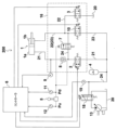
図2は、本発明の第1の実施例における油圧駆動装置の回路図である。
(構成)
図2を参照し、油圧駆動装置200の構成について説明する。FIG. 2 is a circuit diagram of the hydraulic drive device in the first embodiment of the present invention.
(composition)
With reference to FIG. 2, the configuration of the
アキュムレータ4は、ブームシリンダ1からの戻り油を蓄え、ブームシリンダ1の駆動時に圧油を供給する油圧機器である。アキュムレータ4とブームシリンダ1のボトム側油室1aとは油路21を介して接続されており、油路21には制御弁2およびパイロットチェック弁8が配置されている。制御弁2は、コントローラ6からの制御信号を受けて油路21を連通または遮断する。パイロットチェック弁8は、後述するブーム下げパイロット圧Pdが発生している間だけ開弁し、ブーム下げパイロット圧Pdが発生していないときは閉弁状態に保たれる。これにより、ブーム下げ動作時を除き、ブームシリンダ1のボトム側油室1aの圧力が保持されるため、ブームシリンダ1が意図せず収縮動作することを防ぐことができる。油路21のうちボトム側油室1aとパイロットチェック弁8とを接続する油路部分には、ボトム側油室1aの圧力を検出する圧力センサ9が設けられており、圧力センサ9の信号はコントローラ6に入力される。
The
ブームシリンダ1のロッド側油室1bとタンク20とは油路22で接続されており、油路22には制御弁3が配置されている。制御弁3は、コントローラ6からの制御信号を受けて油路22を連通または遮断する。
The rod-
ブームシリンダ1のロッド側油室1bとアキュムレータ4とは油路23で接続されており、油路23には制御弁10が配置されている。制御弁10は、コントローラ6からの制御信号を受けて油路23を連通または遮断する。
The rod-
油圧ポンプ13は主にアキュムレータ4を蓄圧するための油圧機器であり、油圧ポンプ13の吐出ポートは制御弁18および油路24を介してアキュムレータ4に接続されている。制御弁18は、コントローラ6からの制御信号を受けて、図示ノーマル位置から切換操作される。制御弁18がノーマル位置にあるときは油圧ポンプ13の吐出油はタンク20に排出され、制御弁18がノーマル位置から切り換えられると、油圧ポンプ13の吐出油がアキュムレータ4に蓄えられる。油路24には、アキュムレータ4の圧力を検出する圧力センサ19が設けられており、圧力センサ19の信号はコントローラ6に入力される。
The
油路21のうちパイロットチェック弁8と制御弁2とを接続する油路部分は、油路24を介して油路23のうちロッド側油室1bと制御弁10とを接続する部分と接続されており、油路24には制御弁7が配置されている。制御弁7は、後述するブーム下げパイロット圧Pdにより、図示遮断位置から連通位置に切換操作される。これにより、ブーム下げ動作時には、ブームシリンダ1のボトム側がロッド側と連通し、ブームシリンダ1のボトム側が昇圧される。
An oil passage portion of the
オペレータにより操作レバー5がブーム上げ方向に操作されるとブーム上げパイロット圧Puが発生し、ブーム下げ方向に操作されるとブーム下げパイロット圧Pdが発生する。ブーム下げパイロット圧Pdは圧力センサ11によって検出され、ブーム上げパイロット圧Puは圧力センサ12によって検出され、圧力センサ11,12の信号はコントローラ6に入力される。
When the operator operates the
次に、コントローラ6の処理内容について図3および図4を用いて説明する。図3はブームシリンダ1の駆動に係る制御フローを表したものであり、図4はアキュムレータ4の蓄圧動作に係る制御フローを表わしたものである。これらの制御フローは、例えば図示しないキースイッチをONにした場合に開始され、同時並行的に実行される。
Next, the processing contents of the
最初に、図3を参照し、ブームシリンダ1の駆動に係る制御フローについて説明する。 First, with reference to FIG. 3, a control flow related to driving the boom cylinder 1 will be described.
コントローラ6は、まず、圧力センサ12でブーム上げパイロット圧Puが検出されたか否かを判定する(ステップS101)。
The
ステップS101でYes(ブーム上げパイロット圧Puが検出された)と判定した場合は、圧力センサ9で検出したブームシリンダ1のボトム圧が所定の圧力set1よりも高いか否かを判定する(ステップS102)。
If it is determined in step S101 as Yes (boom raising pilot pressure Pu has been detected), it is determined whether the bottom pressure of the boom cylinder 1 detected by the
ステップS102でYes(ブームシリンダ1のボトム圧が所定の圧力set1よりも高い)と判定した場合は、制御弁10は閉じたまま、制御弁2,3を開き(ステップS103)、ステップS101へ戻る。これにより、ロッド側の背圧を抑えつつブームシリンダ1を伸長動作させることができる。
If it is determined as Yes in step S102 (the bottom pressure of boom cylinder 1 is higher than the predetermined pressure set1),
ステップS102でNo(ブームシリンダ1のボトム圧が所定の圧力set1以下である)と判定した場合は、制御弁3は閉じたまま、制御弁2,10を開き(ステップS104)、ステップS101へ戻る。これにより、ロッド側に背圧を立てつつブームシリンダ1を伸張動作させることができる。この時、ブームシリンダ1とアキュムレータ4の圧力差が小さくなり、アキュムレータ4からブームシリンダ1へ圧油を供給する際の圧力損失が抑えられるため、効率良くブームシリンダ1を駆動することが可能となる。
If the determination in step S102 is No (the bottom pressure of the boom cylinder 1 is below the predetermined pressure set1), the
ステップS101でNo(ブーム上げパイロット圧Puが検出されなかった)と判定した場合は、圧力センサ11でブーム下げパイロット圧Pdが検出されたか否かを判定する(ステップS105)。 If it is determined in step S101 as No (boom raising pilot pressure Pu was not detected), it is determined whether boom lowering pilot pressure Pd is detected by the pressure sensor 11 (step S105).
ステップS105でYes(ブーム下げパイロット圧Pdが検出された)と判定した場合は、制御弁3,10は閉じたまま、制御弁2を開き(ステップS106)、ステップS101へ戻る。この時、ブーム下げパイロット圧Pdにより制御弁7は連通位置に切り換えられる。これにより、ブームシリンダ1のボトム側から排出された圧油の一部が制御弁2を介してアキュムレータ4に蓄えられると共に、残りの一部が制御弁7を介してブームシリンダ1のロッド側に供給され、ブームシリンダ1が収縮動作する。
If it is determined in step S105 as Yes (boom lowering pilot pressure Pd has been detected),
ステップS105でNo(ブーム下げパイロット圧Pdが検出されなかった)と判定した場合は、制御弁2,3,10を閉じ(ステップS107)、ステップS101へ戻る。これにより、ブームシリンダ1に作動油を給排する油路21~23が全て遮断されるため、ブームシリンダ1は静止状態に保たれる。
If the determination in step S105 is No (boom lowering pilot pressure Pd was not detected), the
次に、図4を参照し、アキュムレータ4の蓄圧動作に係る制御フローについて説明する。
Next, with reference to FIG. 4, a control flow related to the pressure accumulation operation of the
コントローラ6は、まず、圧力センサ19で検出したアキュムレータ4の圧力(アキュムレータ圧)が所定の圧力set2よりも低いか否かを判定する(ステップS201)。ここでいう所定の圧力set2は、制御弁7を開いてロッド側に背圧を立てた状態でもブームシリンダ1のボトム側油室1aに圧油を供給できる程度の圧力に設定される。
The
ステップS201でYes(アキュムレータ圧が所定の圧力set2よりも低い)と判定した場合は、制御弁18をノーマル位置から切り換えて油圧ポンプ13の吐出ポートをアキュムレータ4に接続し(ステップS202)、ステップS201へ戻る。これにより、油圧ポンプ13の吐出油がアキュムレータ4に蓄えられ、アキュムレータ4の圧力が所定の圧力set2以上に保たれるため、任意のタイミングでブームシリンダ1を駆動することが可能となる。
If it is determined in step S201 as Yes (the accumulator pressure is lower than the predetermined pressure set2), the
ステップS201でNo(アキュムレータ圧が所定の圧力set2以上である)と判定した場合は、制御弁18をノーマル位置に戻して油圧ポンプ13の吐出ポートをタンク20に接続し(ステップS202)、ステップS201へ戻る。これにより、油圧ポンプ13によって必要以上にアキュムレータ4が蓄圧されないため、不要なエネルギー消費を抑えることができる。
(動作)
図2を参照し、油圧駆動装置200の動作について説明する。If it is determined No in step S201 (the accumulator pressure is higher than the predetermined pressure set2), the
(motion)
Referring to FIG. 2, the operation of the
まず、ブーム105の下げ動作(ブームシリンダ1の収縮動作)について説明する。 First, the lowering operation of the boom 105 (the contraction operation of the boom cylinder 1) will be explained.
操作レバー5をブーム下げ方向に操作すると、ブーム下げパイロット圧Pdによってパイロットチェック弁8の圧力保持が解除されると共に制御弁7が開き、ブームシリンダ1のボトム側がロッド側と連通して昇圧される。また同時に、コントローラ6が制御弁2を開くことにより、ボトム側の圧油がアキュムレータ4に流入してエネルギーが回生されると共にブームシリンダ1が収縮する。この時、昇圧されたボトム圧によってアキュムレータ4が蓄圧される。
When the operating
次に、ブーム105の上げ動作(ブームシリンダ1の伸長動作)について説明する。 Next, the raising operation of the boom 105 (the extending operation of the boom cylinder 1) will be explained.
操作レバー5がブーム上げ方向に操作されると、コントローラ6はブーム上げパイロット圧Puが検出されたと判定し、制御弁2を開くと共にブームシリンダ1のボトム圧に応じて制御弁3,10のいずれか一方を開く。具体的には、ブームシリンダ1のボトム圧が所定の圧力set1より高い場合は、制御弁10を閉じた状態で制御弁3を開くことによりロッド側の背圧を抑え、効率よくブームシリンダ1を伸長させる。このとき、アキュムレータ4の圧力とボトム圧との圧力差が小さいため、制御弁2で大きな圧力損失は生じない。一方、ブームシリンダ1のボトム圧が所定の圧力set1以下のときは、制御弁3を閉じた状態で制御弁10を開き、ブームシリンダ1のロッド側をアキュムレータ4に接続することにより、ロッド側に背圧を発生させる。これにより、ブームシリンダ1のボトム側の圧力も上昇するため、ブームシリンダ1のボトム側とアキュムレータ4との圧力差が小さくなり、制御弁2で発生する圧力損失を小さくすることができる。この時、ブームシリンダ1のロッド側に発生させた背圧は制御弁10を介してそのままアキュムレータ4に回生されるため、背圧を発生させることによるエネルギー損失は生じない。
(効果)
本実施例では、作動油を貯留するタンク20と、油圧シリンダ1と、油圧シリンダ1からの戻り油を蓄えるアキュムレータ4と、油圧シリンダ1のボトム側油室1aとアキュムレータ4とを接続する第1油路21に配置された第1制御弁2と、油圧シリンダ1のロッド側油室1bとタンク20とを接続する第2油路22に配置された第2制御弁3とを備えた建設機械100において、ロッド側油室1bとアキュムレータ4とを接続する第3油路23に配置された第3制御弁10と、第1油路21のうちボトム側油室1aと第1制御弁2とを接続する油路部分と第3油路23のうちロッド側油室と第3制御弁10とを接続する油路部分とを接続する第4油路24に配置された第4制御弁7とを備える。When the operating
(effect)
In this embodiment, a
以上のように構成した本実施例によれば、油圧シリンダ1を収縮駆動する際に、第4制御弁7を開いて油圧シリンダ1のボトム側をロッド側に連通させてボトム側を昇圧すると共に、第1制御弁2を開いてボトム側をアキュムレータ4に連通させることにより、アキュムレータ4にボトム側からの戻り油を高圧で蓄えることが可能となる。また、油圧シリンダ1を伸長駆動する際に、第4制御弁7を閉じて油圧シリンダ1のボトム側とロッド側との連通を解除すると共に、第1制御弁2を開いてボトム側をアキュムレータ4に連通させ、かつ第2制御弁3および第3制御弁10のいずれか一方を開くことにより、ロッド側の背圧を調整しつつアキュムレータ4からボトム側に圧油を供給することができる。これにより、アキュムレータ4と油圧シリンダ1のボトム側との圧力差を小さくすることができるため、第1制御弁2における圧力損失を低減することが可能となる。
According to this embodiment configured as described above, when the hydraulic cylinder 1 is driven to contract, the
また、本実施例に係る建設機械100は、油圧シリンダ1の動作を指示するための操作レバー5と、操作レバー5を介して油圧シリンダ1の伸長動作が指示された場合に、第1制御弁2を開くと共に第2制御弁3および第3制御弁10のいずれか一方を開くように制御するコントローラ6とを備え、コントローラ6は、操作レバー5を介して油圧シリンダ1の伸長動作が指示された場合に第4制御弁7を閉じ、操作レバー5を介して油圧シリンダ1の収縮動作が指示された場合に第4制御弁7を開くように制御する。
Furthermore, the
このように構成することにより、操作レバー5を介して油圧シリンダ1の収縮動作が指示された場合は、第4制御弁7が開くことにより油圧シリンダ1のボトム側がロッド側に連通して昇圧され、かつ第1制御弁2が開いてボトム側がアキュムレータ4に連通するため、アキュムレータ4にボトム側の戻り油を高圧で蓄えることができる。また、操作レバー5を介して油圧シリンダ1の伸長動作が指示された場合は、第4制御弁7が閉じることにより油圧シリンダ1のボトム側とロッド側との連通が解除され、かつ第2制御弁3および第3制御弁10のいずれか一方が開いてロッド側がタンク20またはアキュムレータ4に連通するため、ロッド側の背圧を調整することができる。
With this configuration, when the contraction operation of the hydraulic cylinder 1 is instructed via the operating
また、本実施例に係る建設機械100は、ボトム側油室1aの圧力を検出する第1圧力センサ9を備え、コントローラ6は、操作レバー5を介して油圧シリンダ1の伸長動作が指示され、かつ第1圧力センサ9で検出したボトム側油室1aの圧力が第1の所定の圧力set1より高い場合は、第3制御弁10を閉じると共に第2制御弁3を開き、操作レバー5を介して油圧シリンダ1の伸長動作が指示され、かつ第1圧力センサ9で検出したボトム側油室1aの圧力が第1の所定の圧力set1以下の場合は、第2制御弁3を閉じると共に第3制御弁10を開くように制御する。
Furthermore, the
このように構成することにより、操作レバー5を介して油圧シリンダ1の伸長動作が指示された場合でボトム側油室1aの圧力が第1の所定の圧力set1以下のときは、ロッド側をアキュムレータ4に連通させて背圧を立て、アキュムレータ4と油圧シリンダ1のボトム側との圧力差を小さくすることにより、制御弁2における圧力損失を低減することができる。また、操作レバー5を介して油圧シリンダ1の伸長動作が指示された場合でボトム側油室1aの圧力が第1の所定の圧力set1より高いときは、ロッド側をタンク20に連通させて背圧を抑えることにより、効率良く油圧シリンダ1を伸長駆動することができる。
With this configuration, when the extension operation of the hydraulic cylinder 1 is instructed via the operating
また、本実施例に係る建設機械100は、油圧ポンプ13と、油圧ポンプ13の吐出ポートをアキュムレータ4またはタンク20に選択的に接続する第5制御弁18と、アキュムレータ4の圧力を検出する第2圧力センサ19とを備え、コントローラ6は、第2圧力センサ19で検出したアキュムレータ4の圧力が第2の所定の圧力set2以上の場合は、油圧ポンプ13の吐出ポートがタンク20に接続されるように第5制御弁18を制御し、第2圧力センサ19で検出したアキュムレータ4の圧力が第2の所定の圧力set2より低い場合は、油圧ポンプ13の吐出ポートがアキュムレータ4に接続されるように第5制御弁18を制御する。
The
このように構成することにより、アキュムレータ4の圧力が第2の所定の圧力set2以上に保たれるため、任意のタイミングで油圧シリンダ1を駆動することが可能となる。
With this configuration, the pressure in the
図5は、本発明の第2の実施例における油圧駆動装置の回路図である。 FIG. 5 is a circuit diagram of a hydraulic drive device in a second embodiment of the invention.
本実施例に係る油圧駆動装置200は、油圧ポンプ13の吐出油をブームシリンダ1に供給し、ブームシリンダ1から排出される圧油をタンク20に流すための方向制御弁14を備えている。方向制御弁14は、ブーム上げパイロット圧Puによって図示中立位置から左側位置に切換操作され、ブーム下げパイロット圧Pdによって中立位置から右側位置に切換操作される。左側位置に切換操作された方向制御弁14は、油圧ポンプ13の吐出ポートをブームシリンダ1のボトム側油室1aに連通させると共にロッド側油室1bをタンク20に連通させる。右側位置に切換操作された方向制御弁14は、ブームシリンダ1のボトム側油室1aをロッド側油室1bに連通させる。このように、方向制御弁14の右側位置には、第1の実施例における制御弁7(図2に示す)の機能が実装されている。
The
さらに本実施例では、方向制御弁14と油圧シリンダ1の間にパイロットチェック弁15を配置すると共に、方向制御弁14とパイロットチェック弁15を一体のバルブブロック17として構成し、その他の弁をバルブブロック16として構成している。すなわち、バルブブロック17は、従来の油圧ショベルに搭載されている、油圧ポンプからアクチュエータへの圧油の供給を制御するためのメインコントロールバルブを構成し、バルブブロック16は、アキュムレータへの圧油の供給を制御するためのハイブリッド用バルブを構成する。
(効果)
本実施例に係る建設機械100は、油圧ポンプ13を備え、第4制御弁14は、油圧ポンプ13から吐出された圧油を油圧シリンダ1に供給すると共に油圧シリンダ1からの戻り油をタンク20に排出することが可能な方向制御弁14である。Furthermore, in this embodiment, a
(effect)
The
以上のように構成した本実施例によれば、第1の実施例による効果に加えて、以下の効果が得られる。 According to this embodiment configured as described above, the following effects can be obtained in addition to the effects of the first embodiment.
ブームシリンダ1のボトム側をロッド側に連通させて昇圧する機能を方向制御弁14の右側位置に実装したことにより、第1の実施例における制御弁7(図2に示す)が不要となる。また、油圧ポンプ13から方向制御弁14を介して油圧シリンダ1に圧油を供給可能としたことにより、アキュムレータ4をチャージする必要が無くなるため、第1の実施例における制御弁18および圧力センサ19(図2に示す)も不要になる。これにより、油圧回路が複雑になること防ぐことができる。
By implementing the function of communicating the bottom side of the boom cylinder 1 with the rod side and increasing the pressure on the right side of the
また、本実施例に係る建設機械100は、第1油路21のうちボトム側油室1aと第1制御弁2とを接続する油路部分に配置された第1パイロットチェック弁8と、第4油路24のうちボトム側油室1aと方向制御弁14とを接続する油路部分に配置された第2パイロットチェック弁15と、第1制御弁2と第2制御弁3と第3制御弁10と第1パイロットチェック弁8とを一体化する第1バルブブロック16と、方向制御弁14と第2パイロットチェック弁15とを一体化する第2バルブブロック17とを備える。
Furthermore, the
このように構成することにより、ハイブリッド用バルブを従来のメインコントロールバルブにアドオンするだけで建設機械をハイブリッド化できると共に、メインコントロールバルブとハイブリッド用バルブのそれぞれに設けたパイロットチェック弁8,15によりブームシリンダ1のリークを確実に防止することができる。
With this configuration, construction machinery can be hybridized by simply adding a hybrid valve to a conventional main control valve, and the
以上、本発明の実施例について詳述したが、本発明は、上記した実施例に限定されるものではなく、様々な変形例が含まれる。例えば、上記した実施例は、本発明を分かり易く説明するために詳細に説明したものであり、必ずしも説明した全ての構成を備えるものに限定されるものではない。また、ある実施例の構成に他の実施例の構成の一部を加えることも可能であり、ある実施例の構成の一部を削除し、あるいは、他の実施例の一部と置き換えることも可能である。 Although the embodiments of the present invention have been described in detail above, the present invention is not limited to the above-described embodiments, and includes various modifications. For example, the embodiments described above are described in detail to explain the present invention in an easy-to-understand manner, and are not necessarily limited to those having all the configurations described. It is also possible to add a part of the configuration of another embodiment to the configuration of one embodiment, and it is also possible to delete a part of the configuration of one embodiment or replace it with a part of another embodiment. It is possible.
1…ブームシリンダ(油圧シリンダ)、2…制御弁(第1制御弁)、3…制御弁(第2制御弁)、4…アキュムレータ、5…操作レバー、6…コントローラ、7…制御弁(第4制御弁)、8…パイロットチェック弁(第1パイロットチェック弁)、9…圧力センサ(第1圧力センサ)、10…制御弁(第3制御弁)、11…圧力センサ、12…圧力センサ、13…油圧ポンプ、14…方向制御弁(第4制御弁)、15…パイロットチェック弁(第2パイロットチェック弁)、16…バルブブロック(第1バルブブロック)、17…バルブブロック(第2バルブブロック)、18…制御弁(第5制御弁)、19…圧力センサ(第2圧力センサ)、20…タンク、21…油路(第1油路)、22…油路(第2油路)、23…油路(第3油路)、24…油路(第4油路)、25…油路、26…制御弁、100…油圧ショベル(建設機械)、101…走行体、102…旋回体、103…作業装置、104…旋回モータ、105…ブーム、106…アーム、107…バケット、108…アームシリンダ、109…バケットシリンダ、110…運転室、111…カウンタウエイト、112…機械室、113…コントロールバルブ、200…油圧駆動装置。 DESCRIPTION OF SYMBOLS 1...Boom cylinder (hydraulic cylinder), 2...Control valve (first control valve), 3...Control valve (second control valve), 4...Accumulator, 5...Operation lever, 6...Controller, 7...Control valve (first control valve) 4 control valve), 8... Pilot check valve (first pilot check valve), 9... Pressure sensor (first pressure sensor), 10... Control valve (third control valve), 11... Pressure sensor, 12... Pressure sensor, 13... Hydraulic pump, 14... Directional control valve (fourth control valve), 15... Pilot check valve (second pilot check valve), 16... Valve block (first valve block), 17... Valve block (second valve block) ), 18... Control valve (fifth control valve), 19... Pressure sensor (second pressure sensor), 20... Tank, 21... Oil path (first oil path), 22... Oil path (second oil path), 23... Oil path (third oil path), 24... Oil path (fourth oil path), 25... Oil path, 26... Control valve, 100... Hydraulic excavator (construction machine), 101... Traveling body, 102... Swinging body , 103...Work device, 104...Swivel motor, 105...Boom, 106...Arm, 107...Bucket, 108...Arm cylinder, 109...Bucket cylinder, 110...Driver's cab, 111...Counterweight, 112...Machine room, 113... Control valve, 200...hydraulic drive device.
Claims (4)
油圧シリンダと、
前記油圧シリンダからの戻り油を蓄えるアキュムレータと、
前記油圧シリンダのボトム側油室と前記アキュムレータとを接続する第1油路に配置された第1制御弁と、
前記油圧シリンダのロッド側油室と前記タンクとを接続する第2油路に配置された第2制御弁とを備えた建設機械において、
前記ロッド側油室と前記アキュムレータとを接続する第3油路に配置された第3制御弁と、
前記第1油路のうち前記ボトム側油室と前記第1制御弁とを接続する油路部分と前記第3油路のうち前記ロッド側油室と前記第3制御弁とを接続する油路部分とを接続する第4油路に配置された第4制御弁と、
前記油圧シリンダの動作を指示するための操作レバーと、
前記操作レバーを介して入力される指示に応じて、前記第1制御弁、前記第2制御弁および前記第3制御弁を制御するコントローラと、
前記ボトム側油室の圧力を検出する第1圧力センサとを備え、
前記第4制御弁は、前記操作レバーを介して前記油圧シリンダの伸長動作が指示された場合に閉じ、前記操作レバーを介して前記油圧シリンダの収縮動作が指示された場合に開くように構成されており、
前記コントローラは、
前記操作レバーを介して前記油圧シリンダの伸長動作が指示され、かつ前記第1圧力センサで検出した前記ボトム側油室の圧力が第1の所定の圧力より高い場合に、前記第1制御弁および前記第2制御弁を開くと共に前記第3制御弁を閉じ、
前記操作レバーを介して前記油圧シリンダの伸長動作が指示され、かつ前記第1圧力センサで検出した前記ボトム側油室の圧力が前記第1の所定の圧力以下の場合に、前記第1制御弁および前記第3制御弁を開くと共に前記第2制御弁を閉じる
ことを特徴とする建設機械。 A tank for storing hydraulic oil,
a hydraulic cylinder;
an accumulator that stores return oil from the hydraulic cylinder;
a first control valve disposed in a first oil passage connecting the bottom side oil chamber of the hydraulic cylinder and the accumulator;
A construction machine comprising a second control valve disposed in a second oil passage connecting the rod-side oil chamber of the hydraulic cylinder and the tank,
a third control valve disposed in a third oil passage connecting the rod-side oil chamber and the accumulator;
An oil passage portion of the first oil passage that connects the bottom oil chamber and the first control valve, and an oil passage that connects the rod side oil chamber and the third control valve of the third oil passage. a fourth control valve disposed in a fourth oil passage connecting the parts ;
an operating lever for instructing the operation of the hydraulic cylinder;
a controller that controls the first control valve, the second control valve, and the third control valve in accordance with instructions input via the operating lever;
and a first pressure sensor that detects the pressure in the bottom side oil chamber ,
The fourth control valve is configured to close when an extension operation of the hydraulic cylinder is instructed via the operation lever, and to open when a contraction operation of the hydraulic cylinder is instructed via the operation lever. and
The controller includes:
When an extension operation of the hydraulic cylinder is instructed via the operating lever and the pressure in the bottom side oil chamber detected by the first pressure sensor is higher than a first predetermined pressure, the first control valve and opening the second control valve and closing the third control valve;
When an extension operation of the hydraulic cylinder is instructed via the operating lever and the pressure in the bottom side oil chamber detected by the first pressure sensor is equal to or lower than the first predetermined pressure, the first control valve and opening the third control valve and closing the second control valve.
A construction machine characterized by:
油圧ポンプを備え、
前記第4制御弁は、前記油圧ポンプから吐出された圧油を前記油圧シリンダに供給すると共に前記油圧シリンダからの戻り油を前記タンクに排出することが可能な方向制御弁である
ことを特徴とする建設機械。 The construction machine according to claim 1,
Equipped with a hydraulic pump,
The fourth control valve is a directional control valve capable of supplying pressure oil discharged from the hydraulic pump to the hydraulic cylinder and discharging return oil from the hydraulic cylinder to the tank. construction machinery.
前記第1油路のうち前記ボトム側油室と前記第1制御弁とを接続する油路部分に配置された第1パイロットチェック弁と、
前記第4油路のうち前記ボトム側油室と前記方向制御弁とを接続する油路部分に配置された第2パイロットチェック弁と、
前記第1制御弁と前記第2制御弁と前記第3制御弁と前記第1パイロットチェック弁とを一体化する第1バルブブロックと、
前記方向制御弁と前記第2パイロットチェック弁とを一体化する第2バルブブロックとを備えた
ことを特徴とする建設機械。 The construction machine according to claim 2 ,
a first pilot check valve disposed in a portion of the first oil passage that connects the bottom side oil chamber and the first control valve;
a second pilot check valve disposed in a portion of the fourth oil passage that connects the bottom side oil chamber and the directional control valve;
a first valve block that integrates the first control valve, the second control valve, the third control valve, and the first pilot check valve;
A construction machine comprising: a second valve block that integrates the directional control valve and the second pilot check valve.
油圧ポンプと、
前記油圧ポンプの吐出ポートを前記アキュムレータまたは前記タンクに選択的に接続する第5制御弁と、
前記アキュムレータの圧力を検出する第2圧力センサとを備え、
前記コントローラは、前記第2圧力センサで検出した前記アキュムレータの圧力が第2の所定の圧力以上の場合は、前記油圧ポンプの吐出ポートが前記タンクに接続されるように前記第5制御弁を制御し、前記第2圧力センサで検出した前記アキュムレータの圧力が前記第2の所定の圧力より低い場合は、前記油圧ポンプの吐出ポートが前記アキュムレータに接続されるように前記第5制御弁を制御する
ことを特徴とする建設機械。 The construction machine according to claim 1 ,
hydraulic pump and
a fifth control valve that selectively connects a discharge port of the hydraulic pump to the accumulator or the tank;
and a second pressure sensor that detects the pressure of the accumulator,
The controller controls the fifth control valve so that the discharge port of the hydraulic pump is connected to the tank when the pressure in the accumulator detected by the second pressure sensor is equal to or higher than a second predetermined pressure. If the pressure of the accumulator detected by the second pressure sensor is lower than the second predetermined pressure, the fifth control valve is controlled so that the discharge port of the hydraulic pump is connected to the accumulator. A construction machine characterized by:
Applications Claiming Priority (3)
| Application Number | Priority Date | Filing Date | Title |
|---|---|---|---|
| JP2020104904 | 2020-06-17 | ||
| JP2020104904 | 2020-06-17 | ||
| PCT/JP2021/014801 WO2021256060A1 (en) | 2020-06-17 | 2021-04-07 | Construction machine |
Publications (2)
| Publication Number | Publication Date |
|---|---|
| JPWO2021256060A1 JPWO2021256060A1 (en) | 2021-12-23 |
| JP7397194B2 true JP7397194B2 (en) | 2023-12-12 |
Family
ID=79267726
Family Applications (1)
| Application Number | Title | Priority Date | Filing Date |
|---|---|---|---|
| JP2022532330A Active JP7397194B2 (en) | 2020-06-17 | 2021-04-07 | construction machinery |
Country Status (6)
| Country | Link |
|---|---|
| US (1) | US20230084767A1 (en) |
| EP (1) | EP4098809A4 (en) |
| JP (1) | JP7397194B2 (en) |
| KR (1) | KR20220127328A (en) |
| CN (1) | CN115190929B (en) |
| WO (1) | WO2021256060A1 (en) |
Families Citing this family (1)
| Publication number | Priority date | Publication date | Assignee | Title |
|---|---|---|---|---|
| JP2022001769A (en) * | 2020-06-19 | 2022-01-06 | 川崎重工業株式会社 | Hydraulic drive system |
Citations (2)
| Publication number | Priority date | Publication date | Assignee | Title |
|---|---|---|---|---|
| JP2011069432A (en) | 2009-09-25 | 2011-04-07 | Caterpillar Sarl | Regenerative control device of working machine |
| WO2013059020A1 (en) | 2011-10-21 | 2013-04-25 | Caterpillar Inc. | Closed-loop hydraulic system having regeneration configuration |
Family Cites Families (12)
| Publication number | Priority date | Publication date | Assignee | Title |
|---|---|---|---|---|
| DE69735941T2 (en) * | 1996-12-03 | 2006-11-02 | Shin Caterpillar Mitsubishi Ltd. | CONTROL DEVICE FOR A CONSTRUCTION MACHINE |
| JP2002097673A (en) * | 2000-09-22 | 2002-04-02 | Shin Caterpillar Mitsubishi Ltd | Hydraulic circuit of work machine |
| US7325398B2 (en) * | 2004-03-05 | 2008-02-05 | Deere & Company | Closed circuit energy recovery system for a work implement |
| JP2009275771A (en) | 2008-05-13 | 2009-11-26 | Caterpillar Japan Ltd | Fluid pressure actuator control circuit |
| JP2009275769A (en) | 2008-05-13 | 2009-11-26 | Caterpillar Japan Ltd | Fluid pressure cylinder control circuit |
| JP5183558B2 (en) * | 2009-04-14 | 2013-04-17 | 日立建機株式会社 | Work machine |
| JP5368943B2 (en) * | 2009-11-10 | 2013-12-18 | 川崎重工業株式会社 | Hydraulic control device |
| JP6138050B2 (en) * | 2010-12-13 | 2017-05-31 | イートン コーポレーションEaton Corporation | Hydraulic system for energy recovery in work machines such as wheel loaders |
| JP6453711B2 (en) * | 2015-06-02 | 2019-01-16 | 日立建機株式会社 | Pressure oil recovery system for work machines |
| DE102016002134A1 (en) * | 2016-02-23 | 2017-08-24 | Liebherr-Mining Equipment Colmar Sas | Device for recuperation of hydraulic energy and working machine with appropriate device |
| US10801532B2 (en) * | 2017-03-29 | 2020-10-13 | Hitachi Construction Machinery Co., Ltd. | Work machine |
| JP2019031989A (en) * | 2017-08-04 | 2019-02-28 | コベルコ建機株式会社 | Construction machine |
-
2021
- 2021-04-07 JP JP2022532330A patent/JP7397194B2/en active Active
- 2021-04-07 KR KR1020227029436A patent/KR20220127328A/en not_active Application Discontinuation
- 2021-04-07 EP EP21826770.6A patent/EP4098809A4/en active Pending
- 2021-04-07 CN CN202180017571.4A patent/CN115190929B/en active Active
- 2021-04-07 US US17/802,745 patent/US20230084767A1/en active Pending
- 2021-04-07 WO PCT/JP2021/014801 patent/WO2021256060A1/en unknown
Patent Citations (2)
| Publication number | Priority date | Publication date | Assignee | Title |
|---|---|---|---|---|
| JP2011069432A (en) | 2009-09-25 | 2011-04-07 | Caterpillar Sarl | Regenerative control device of working machine |
| WO2013059020A1 (en) | 2011-10-21 | 2013-04-25 | Caterpillar Inc. | Closed-loop hydraulic system having regeneration configuration |
Also Published As
| Publication number | Publication date |
|---|---|
| WO2021256060A1 (en) | 2021-12-23 |
| EP4098809A4 (en) | 2024-02-28 |
| CN115190929B (en) | 2024-03-29 |
| US20230084767A1 (en) | 2023-03-16 |
| JPWO2021256060A1 (en) | 2021-12-23 |
| EP4098809A1 (en) | 2022-12-07 |
| KR20220127328A (en) | 2022-09-19 |
| CN115190929A (en) | 2022-10-14 |
Similar Documents
| Publication | Publication Date | Title |
|---|---|---|
| KR101932304B1 (en) | Hydraulic drive device for working machine | |
| EP3203089A1 (en) | Work vehicle hydraulic drive system | |
| WO2019049435A1 (en) | Construction machine | |
| JP3816893B2 (en) | Hydraulic drive | |
| JP4384977B2 (en) | Hydraulic drive | |
| JP2004301214A (en) | Hydraulic driving device for work vehicle | |
| JP7397194B2 (en) | construction machinery | |
| CN113396288B (en) | Engineering machinery | |
| WO2021256059A1 (en) | Construction machine | |
| WO2021251140A1 (en) | Hydraulic shovel driving system | |
| JP2018053474A (en) | Hydraulic drive device for construction machine with booms | |
| CN113302403A (en) | Hydraulic control circuit for a work machine | |
| WO2021261051A1 (en) | Construction machine | |
| CN115244251B (en) | Engineering machinery | |
| JP2018172878A (en) | Construction machine | |
| JP7389728B2 (en) | Hydraulic excavator drive system | |
| JP2013044399A (en) | Hydraulic drive system | |
| CN113167056B (en) | Hydraulic control circuit for a work machine | |
| JP3531904B2 (en) | Hydraulic control circuit of work machine | |
| JP2003056507A (en) | Hydraulic circuit of work machine with telescopic arm | |
| JP2023142310A (en) | Work machine | |
| JPH07305380A (en) | Hydraulic drive gear of hydraulic shovel equipped with loader front | |
| CN117897538A (en) | Excavator | |
| WO1995007390A1 (en) | Hydraulic driving device for a construction | |
| JP2019215043A (en) | Hydraulic driving device and working machine comprising the same |
Legal Events
| Date | Code | Title | Description |
|---|---|---|---|
| A621 | Written request for application examination |
Free format text: JAPANESE INTERMEDIATE CODE: A621 Effective date: 20220817 |
|
| A131 | Notification of reasons for refusal |
Free format text: JAPANESE INTERMEDIATE CODE: A131 Effective date: 20230926 |
|
| A521 | Request for written amendment filed |
Free format text: JAPANESE INTERMEDIATE CODE: A523 Effective date: 20231121 |
|
| TRDD | Decision of grant or rejection written | ||
| A01 | Written decision to grant a patent or to grant a registration (utility model) |
Free format text: JAPANESE INTERMEDIATE CODE: A01 Effective date: 20231128 |
|
| A61 | First payment of annual fees (during grant procedure) |
Free format text: JAPANESE INTERMEDIATE CODE: A61 Effective date: 20231130 |
|
| R150 | Certificate of patent or registration of utility model |
Ref document number: 7397194 Country of ref document: JP Free format text: JAPANESE INTERMEDIATE CODE: R150 |