JP7396014B2 - Setting device and controls - Google Patents
Setting device and controls Download PDFInfo
- Publication number
- JP7396014B2 JP7396014B2 JP2019225847A JP2019225847A JP7396014B2 JP 7396014 B2 JP7396014 B2 JP 7396014B2 JP 2019225847 A JP2019225847 A JP 2019225847A JP 2019225847 A JP2019225847 A JP 2019225847A JP 7396014 B2 JP7396014 B2 JP 7396014B2
- Authority
- JP
- Japan
- Prior art keywords
- light
- operator
- light emitting
- slide
- section
- Prior art date
- Legal status (The legal status is an assumption and is not a legal conclusion. Google has not performed a legal analysis and makes no representation as to the accuracy of the status listed.)
- Active
Links
Images


Classifications
-
- G—PHYSICS
- G10—MUSICAL INSTRUMENTS; ACOUSTICS
- G10H—ELECTROPHONIC MUSICAL INSTRUMENTS; INSTRUMENTS IN WHICH THE TONES ARE GENERATED BY ELECTROMECHANICAL MEANS OR ELECTRONIC GENERATORS, OR IN WHICH THE TONES ARE SYNTHESISED FROM A DATA STORE
- G10H1/00—Details of electrophonic musical instruments
- G10H1/0008—Associated control or indicating means
- G10H1/0016—Means for indicating which keys, frets or strings are to be actuated, e.g. using lights or leds
-
- G—PHYSICS
- G10—MUSICAL INSTRUMENTS; ACOUSTICS
- G10H—ELECTROPHONIC MUSICAL INSTRUMENTS; INSTRUMENTS IN WHICH THE TONES ARE GENERATED BY ELECTROMECHANICAL MEANS OR ELECTRONIC GENERATORS, OR IN WHICH THE TONES ARE SYNTHESISED FROM A DATA STORE
- G10H1/00—Details of electrophonic musical instruments
- G10H1/0008—Associated control or indicating means
-
- G—PHYSICS
- G06—COMPUTING OR CALCULATING; COUNTING
- G06F—ELECTRIC DIGITAL DATA PROCESSING
- G06F3/00—Input arrangements for transferring data to be processed into a form capable of being handled by the computer; Output arrangements for transferring data from processing unit to output unit, e.g. interface arrangements
- G06F3/01—Input arrangements or combined input and output arrangements for interaction between user and computer
- G06F3/03—Arrangements for converting the position or the displacement of a member into a coded form
- G06F3/033—Pointing devices displaced or positioned by the user, e.g. mice, trackballs, pens or joysticks; Accessories therefor
- G06F3/0362—Pointing devices displaced or positioned by the user, e.g. mice, trackballs, pens or joysticks; Accessories therefor with detection of one-dimensional [1D] translations or rotations of an operating part of the device, e.g. scroll wheels, sliders, knobs, rollers or belts
-
- G—PHYSICS
- G06—COMPUTING OR CALCULATING; COUNTING
- G06F—ELECTRIC DIGITAL DATA PROCESSING
- G06F3/00—Input arrangements for transferring data to be processed into a form capable of being handled by the computer; Output arrangements for transferring data from processing unit to output unit, e.g. interface arrangements
- G06F3/01—Input arrangements or combined input and output arrangements for interaction between user and computer
- G06F3/048—Interaction techniques based on graphical user interfaces [GUI]
- G06F3/0484—Interaction techniques based on graphical user interfaces [GUI] for the control of specific functions or operations, e.g. selecting or manipulating an object, an image or a displayed text element, setting a parameter value or selecting a range
- G06F3/04847—Interaction techniques to control parameter settings, e.g. interaction with sliders or dials
-
- G—PHYSICS
- G10—MUSICAL INSTRUMENTS; ACOUSTICS
- G10G—REPRESENTATION OF MUSIC; RECORDING MUSIC IN NOTATION FORM; ACCESSORIES FOR MUSIC OR MUSICAL INSTRUMENTS NOT OTHERWISE PROVIDED FOR, e.g. SUPPORTS
- G10G1/00—Means for the representation of music
- G10G1/02—Chord or note indicators, fixed or adjustable, for keyboard of fingerboards
-
- G—PHYSICS
- G10—MUSICAL INSTRUMENTS; ACOUSTICS
- G10H—ELECTROPHONIC MUSICAL INSTRUMENTS; INSTRUMENTS IN WHICH THE TONES ARE GENERATED BY ELECTROMECHANICAL MEANS OR ELECTRONIC GENERATORS, OR IN WHICH THE TONES ARE SYNTHESISED FROM A DATA STORE
- G10H1/00—Details of electrophonic musical instruments
- G10H1/18—Selecting circuits
- G10H1/24—Selecting circuits for selecting plural preset register stops
-
- G—PHYSICS
- G10—MUSICAL INSTRUMENTS; ACOUSTICS
- G10H—ELECTROPHONIC MUSICAL INSTRUMENTS; INSTRUMENTS IN WHICH THE TONES ARE GENERATED BY ELECTROMECHANICAL MEANS OR ELECTRONIC GENERATORS, OR IN WHICH THE TONES ARE SYNTHESISED FROM A DATA STORE
- G10H1/00—Details of electrophonic musical instruments
- G10H1/32—Constructional details
- G10H1/34—Switch arrangements, e.g. keyboards or mechanical switches specially adapted for electrophonic musical instruments
- G10H1/344—Structural association with individual keys
-
- G—PHYSICS
- G10—MUSICAL INSTRUMENTS; ACOUSTICS
- G10H—ELECTROPHONIC MUSICAL INSTRUMENTS; INSTRUMENTS IN WHICH THE TONES ARE GENERATED BY ELECTROMECHANICAL MEANS OR ELECTRONIC GENERATORS, OR IN WHICH THE TONES ARE SYNTHESISED FROM A DATA STORE
- G10H2210/00—Aspects or methods of musical processing having intrinsic musical character, i.e. involving musical theory or musical parameters or relying on musical knowledge, as applied in electrophonic musical tools or instruments
- G10H2210/155—Musical effects
-
- G—PHYSICS
- G10—MUSICAL INSTRUMENTS; ACOUSTICS
- G10H—ELECTROPHONIC MUSICAL INSTRUMENTS; INSTRUMENTS IN WHICH THE TONES ARE GENERATED BY ELECTROMECHANICAL MEANS OR ELECTRONIC GENERATORS, OR IN WHICH THE TONES ARE SYNTHESISED FROM A DATA STORE
- G10H2220/00—Input/output interfacing specifically adapted for electrophonic musical tools or instruments
- G10H2220/021—Indicator, i.e. non-screen output user interfacing, e.g. visual or tactile instrument status or guidance information using lights, LEDs or seven segments displays
- G10H2220/026—Indicator, i.e. non-screen output user interfacing, e.g. visual or tactile instrument status or guidance information using lights, LEDs or seven segments displays associated with a key or other user input device, e.g. key indicator lights
- G10H2220/031—Blinking or flashing indicator lights
-
- G—PHYSICS
- G10—MUSICAL INSTRUMENTS; ACOUSTICS
- G10H—ELECTROPHONIC MUSICAL INSTRUMENTS; INSTRUMENTS IN WHICH THE TONES ARE GENERATED BY ELECTROMECHANICAL MEANS OR ELECTRONIC GENERATORS, OR IN WHICH THE TONES ARE SYNTHESISED FROM A DATA STORE
- G10H2220/00—Input/output interfacing specifically adapted for electrophonic musical tools or instruments
- G10H2220/021—Indicator, i.e. non-screen output user interfacing, e.g. visual or tactile instrument status or guidance information using lights, LEDs or seven segments displays
- G10H2220/026—Indicator, i.e. non-screen output user interfacing, e.g. visual or tactile instrument status or guidance information using lights, LEDs or seven segments displays associated with a key or other user input device, e.g. key indicator lights
- G10H2220/061—LED, i.e. using a light-emitting diode as indicator
-
- G—PHYSICS
- G10—MUSICAL INSTRUMENTS; ACOUSTICS
- G10H—ELECTROPHONIC MUSICAL INSTRUMENTS; INSTRUMENTS IN WHICH THE TONES ARE GENERATED BY ELECTROMECHANICAL MEANS OR ELECTRONIC GENERATORS, OR IN WHICH THE TONES ARE SYNTHESISED FROM A DATA STORE
- G10H2220/00—Input/output interfacing specifically adapted for electrophonic musical tools or instruments
- G10H2220/091—Graphical user interface [GUI] specifically adapted for electrophonic musical instruments, e.g. interactive musical displays, musical instrument icons or menus; Details of user interactions therewith
-
- G—PHYSICS
- G10—MUSICAL INSTRUMENTS; ACOUSTICS
- G10H—ELECTROPHONIC MUSICAL INSTRUMENTS; INSTRUMENTS IN WHICH THE TONES ARE GENERATED BY ELECTROMECHANICAL MEANS OR ELECTRONIC GENERATORS, OR IN WHICH THE TONES ARE SYNTHESISED FROM A DATA STORE
- G10H2220/00—Input/output interfacing specifically adapted for electrophonic musical tools or instruments
- G10H2220/155—User input interfaces for electrophonic musical instruments
- G10H2220/221—Keyboards, i.e. configuration of several keys or key-like input devices relative to one another
Landscapes
- Engineering & Computer Science (AREA)
- Physics & Mathematics (AREA)
- Acoustics & Sound (AREA)
- Multimedia (AREA)
- General Engineering & Computer Science (AREA)
- Theoretical Computer Science (AREA)
- Human Computer Interaction (AREA)
- General Physics & Mathematics (AREA)
- Electrophonic Musical Instruments (AREA)
- Position Input By Displaying (AREA)
- Mechanical Control Devices (AREA)
Description
本発明は、パラメータを設定するための装置に関する。 The present invention relates to a device for setting parameters.
電子楽器は、様々なパラメータに基づいて音色を変更することができる。パラメータの値は、電子楽器に設けられた操作子によって変更される。この操作子によれば、ユーザが演奏しながら音色を変更することもできる。演奏時の環境によっては、操作子そのものが見えにくい場合もあり、操作子の指示値について高い視認性が望まれる。例えば、特許文献1には、操作子の近傍に、その操作値の指示値に対応した目盛画像を表示する技術が開示されている。
Electronic musical instruments can change timbre based on various parameters. The value of the parameter is changed by an operator provided on the electronic musical instrument. According to this operator, the user can also change the tone while playing. Depending on the environment during performance, the controls themselves may be difficult to see, so high visibility of the indicated values of the controls is desired. For example,
音色の制御は、多くのパラメータによって実現される。一方、多くのパラメータをリアルタイムに制御するためには、多くの操作子が必要となる。近傍に目盛画像が配置されたスライド操作子を並べて用いる場合、スライド操作子と目盛画像とが交互に配置される。そのため、隣接するスライド操作子との距離によっては、スライド操作子の指示値と目盛画像との対応関係がわかりにくくなる場合があった。 Control of timbre is achieved by many parameters. On the other hand, in order to control many parameters in real time, many operators are required. When slide operators with scale images arranged nearby are used side by side, the slide operators and the scale images are arranged alternately. Therefore, depending on the distance between adjacent slide operators, it may be difficult to understand the correspondence between the indicated value of the slide operator and the scale image.
本発明の目的の一つは、操作子の指示値に対応する表示の視認性を向上させることにある。 One of the objects of the present invention is to improve the visibility of the display corresponding to the instruction value of the operator.
本発明の一実施形態によれば、第1領域内を移動することによって、第1パラメータの設定値を指定するための操作子と、前記第1領域内に前記設定値に応じて発光範囲が変化する第2領域を有し、前記操作子によって前記第2領域の一部が覆われる発光部と、を備える設定装置を提供する。 According to an embodiment of the present invention, an operator for specifying a setting value of the first parameter by moving within the first area, and a light emission range within the first area according to the setting value. A setting device is provided, including a light emitting section having a second area that changes, and a part of the second area being covered by the operator.
前記操作子は、前記第2領域のうち前記操作子に覆われた部分から発生した光を前記操作子の外面に誘導する誘導部を含んでもよい。 The operator may include a guide portion that guides light generated from a portion of the second region covered by the operator to an outer surface of the operator.
前記第1領域は、第1方向に長手を有する領域であり、前記発光範囲は、前記第1方向に沿って変化し、前記誘導部は、前記操作子の外面のうち前記第1方向に長手を有する範囲に前記光を誘導してもよい。 The first region is a region having a longitudinal direction in the first direction, the light emitting range changes along the first direction, and the guiding part is a region having a longitudinal direction in the first direction on the outer surface of the operator. The light may be guided to a range having a .
前記第1方向における前記第2領域の第1端部から第2端部までの長さは、前記第1方向における前記第1領域の第3端部から第4端部までの長さよりも短く、前記第1端部と前記第3端部との距離は、前記第2端部と前記第4端部との距離よりも短く、前記発光範囲は、前記第2領域のうち前記操作部に覆われた部分と前記第1端部との間の少なくとも一部を含んでもよい。 The length from the first end to the second end of the second region in the first direction is shorter than the length from the third end to the fourth end of the first region in the first direction. , the distance between the first end and the third end is shorter than the distance between the second end and the fourth end, and the light emitting range is located within the second region toward the operating section. It may include at least a portion between the covered portion and the first end.
前記第1方向と直交する第2方向において、前記操作子の少なくとも一端は、前記第2領域よりも外側に位置してもよい。 In a second direction perpendicular to the first direction, at least one end of the operator may be located outside the second region.
記憶部から読み出した情報に基づいて前記設定値を更新する更新部をさらに含んでもよい。 The image forming apparatus may further include an updating section that updates the setting value based on information read from the storage section.
前記発光部は、発光素子、および前記発光素子が発生させた光を前記第2領域へ導く部材を含み、前記第2領域の外側に前記発光素子が配置されてもよい。 The light emitting unit may include a light emitting element and a member that guides light generated by the light emitting element to the second region, and the light emitting element may be disposed outside the second region.
また、本発明の位置実施形態によれば、筐体に対して第1領域内を移動することによって、音に関する第1パラメータの設定値を指定するための操作子であって、遮光性を有する第1部分と、前記操作子の第1面から前記第1面と対向する第2面までの透光性を有する第2部分と、を含む、操作子が提供される。 Further, according to the positional embodiment of the present invention, there is provided an operator for specifying a setting value of a first parameter related to sound by moving within the first area with respect to the casing, the operator having a light-shielding property. An operator is provided that includes a first portion and a second portion having translucency from a first surface of the operator to a second surface opposite to the first surface.
前記第1部分は、前記第2部分によって2つの領域に区分されてもよい。 The first portion may be divided into two regions by the second portion.
本発明によれば、操作子の指示値に対応する表示の視認性を向上させることができる。 According to the present invention, it is possible to improve the visibility of the display corresponding to the instruction value of the operator.
以下、本発明の一実施形態における電子鍵盤装置について、図面を参照しながら詳細に説明する。以下に示す実施形態は本発明の実施形態の一例であって、本発明はこれらの実施形態に限定して解釈されるものではない。なお、本実施形態で参照する図面において、同一部分または同様な機能を有する部分には同一の符号または類似の符号(数字の後にA、Bなど付しただけの符号)を付し、その繰り返しの説明は省略する場合がある。また、図面の寸法比率は説明の都合上実際の比率とは異なったり、構成の一部が図面から省略されたりする場合がある。 Hereinafter, an electronic keyboard device according to an embodiment of the present invention will be described in detail with reference to the drawings. The embodiments shown below are examples of the embodiments of the present invention, and the present invention is not construed as being limited to these embodiments. In the drawings referred to in this embodiment, the same parts or parts having similar functions are denoted by the same or similar symbols (numerals followed by numbers such as A, B, etc.), and their repetitions are indicated. Explanation may be omitted. Furthermore, for convenience of explanation, the dimensional ratios in the drawings may differ from the actual ratios, or a part of the structure may be omitted from the drawings.
<第1実施形態>
[1.電子鍵盤装置]
図1は、本発明の第1実施形態における電子鍵盤装置の外観を説明する図である。電子鍵盤装置1は、筐体95に支持された複数の鍵を含む鍵盤部80を備えるシンセサイザである。電子鍵盤装置1は、ユーザによって鍵が操作されたり、シーケンサによる曲データの再生が指示されたりすると、音信号を生成する。音信号は、信号出力部65から出力される。音信号は、スピーカ60から出力されてもよい。
<First embodiment>
[1. Electronic keyboard device]
FIG. 1 is a diagram illustrating the appearance of an electronic keyboard device according to a first embodiment of the present invention. The
電子鍵盤装置1は、筐体95に配置された複数(この例では9個)のスライド操作子25a~25iによって、音信号を生成する際に用いる複数のパラメータの設定値を変更することができる。また、スライド操作子25a~25iによって、出力される音をリアルタイムに変化させることもできる。以下、スライド操作子25a~25iをそれぞれ区別して説明する必要がない場合には、単にスライド操作子25と記載する場合がある。この例では、スライド操作子25a~25iは、トーンホイール・オルガンに用いられるドローバーと同じような効果を得るための操作子である。すなわち、スライド操作子25a~25iは、それぞれ、オルガンの音色の場合における倍音の成分を調整するために用いられる。また、ロータリエンコーダおよびスイッチ等の操作部70によってもパラメータの設定値を変更できるようにしてもよい。
The
スライド操作子25a~25iには、それぞれの指示位置を表示するための指示位置表示部35a~35iがそれぞれ対応して配置されている。以下、指示位置表示部35a~35iをまとめた構成として、指示位置表示部35と記載する場合がある。スライド操作子25と指示位置表示部35との関係の詳細については後述する。以下の説明においては、説明の便宜上、電子鍵盤装置1に対して、演奏者がいる側(筐体95に対して鍵盤部80が存在する側)を手前側(または前側という場合もある)、演奏者とは反対側を奥側(または後側という場合もある)として定義する。また、左右、上下についても、演奏者から見た場合の方向として定義する。以下、電子鍵盤装置1の構成について、さらに図2も用いて詳述する。
Indicated position display
図2は、本発明の第1実施形態における電子鍵盤装置の構成を説明する図である。電子鍵盤装置1は、制御部10、記憶部18、入力装置20a~20i、発光装置30a~30i、音源部40、表示部50、スピーカ60、信号出力部65、操作部70、鍵盤部80、およびインターフェース90を備える。以下、入力装置20a~20iをそれぞれ区別して説明する必要がない場合には、単に入力装置20と記載する場合がある。発光装置30a~30iをそれぞれ区別して説明する必要がない場合には、単に発光装置30と記載する場合がある。発光装置30は、指示位置表示部35および発光駆動部36を含む。指示位置表示部35a~35iと発光駆動部36a~36iとはそれぞれ対応している。以下、発光駆動部36a~36iをそれぞれ区別して説明する必要がない場合には、単に発光駆動部36と記載する場合がある。発光駆動部36によって、対応する指示位置表示部35の表示内容が制御される。
FIG. 2 is a diagram illustrating the configuration of the electronic keyboard device according to the first embodiment of the present invention. The
また、電子鍵盤装置1は、複数のセンサを備える。この例では、複数のセンサには、指示位置検出部28a~28iおよび押鍵検出部88が含まれる。以下、指示位置検出部28a~28iをそれぞれ区別して説明する必要がない場合には、単に指示位置検出部28と記載する場合がある。上述した入力装置20は、スライド操作子25および指示位置検出部28を含む。
Further, the
制御部10は、CPUなどの演算処理回路、およびRAM、ROMなどの記憶装置を含むコンピュータの一例である。制御部10は、記憶部18に記憶された制御プログラムをCPUにより実行して、プログラムに記述された命令によって様々な機能を電子鍵盤装置1において実現させる。様々な機能には、後述する音制御機能100(図5参照)が含まれる。このプログラムは、外部装置から提供されて、記憶部18にインストールされてもよい。
The
鍵盤部80は、筐体95に回転可能に支持された複数の鍵を含む。押鍵検出部88は、押下された鍵およびその鍵の押下量(例えばベロシティ、経時変化)に応じた検出信号KVを制御部10に出力する。操作部70は、操作ボタン、ロータリエンコーダなどの装置であり、ユーザによって電子鍵盤装置1への指示が入力される。操作部70は、入力操作によるユーザの指示に応じた操作信号Ssを制御部10に出力する。ユーザの指示には、スライド操作子25の指示位置の設定を登録する指示、および指示位置の設定を設定データに基づいて更新する指示が含まれる。
The
記憶部18は、不揮発性メモリなどの記憶装置であって、制御部10によって実行される制御プログラムを記憶する領域、および音源部40の制御に用いるためのパラメータを記憶する領域を含む。このパラメータのうち、設定データが設定データ記憶領域181(図5参照)に登録される。設定データは、スライド操作子25の指示位置の設定を規定したデータである。複数の設定データが設定データ記憶領域181に登録されてもよい。上述したように、ユーザが指示することで、この設定データが記憶部18に登録されたり、読み出されたりする。
The
表示部50は、液晶ディスプレイなどの表示装置であり、制御部10による制御によって様々な画面を表示する。インターフェース90は、この例では、コントローラなどの外部装置を電子鍵盤装置1に接続するための端子を含む。インターフェース90には、MIDIデータの送受信をするための端子などが含まれていてもよい。
The
音源部40は、制御部10からの音源制御信号Ctに基づいて音信号を生成する。生成した音信号は、信号出力部65に供給され、さらにスピーカ60に供給されてもよい。スピーカ60に音信号が出力されるか否かは設定に応じて決められてもよい。音源制御信号Ctは、ノートナンバ、ノートオン、ノートオフなど各音の発生を制御するための情報、リバーブ、コーラス、フェイザ、ワウなどエフェクトを制御するための情報など、音信号を生成するために必要な情報を含む。この例では、音信号を生成するために必要な情報には、オルガンの倍音成分の量を制御するための情報も含まれる。
The
なお、音源部40は、DSPなどのハードウェアによって実現されてもよいし、ソフトウェアによって実現されてもよい。後者である場合、音源部40の機能は、メモリなどに記憶されたプログラムをCPUにより実行することによって実現されてもよい。また、音源部40の機能の一部がソフトウェアによって実現され、残りの部分がハードウェアによって実現されてもよい。
Note that the
信号出力部65は、音源部40から供給される音信号を、外部装置へ出力するための端子である。スピーカ60は、制御部10または音源部40から供給される音信号を増幅して出力することによって、音信号に応じた音を発生する。
The
スライド操作子25(25a~25i)は、鍵が並ぶスケール方向(第2方向)に沿って、並んで配置されている。スケール方向は左右方向に対応する。また、スライド操作子25は、スケール方向と直交する方向(第1方向)に移動して、指示位置を複数段階(この例では9段階)で変更することができる。以下、スライド操作子25が移動する方向をスライド方向という場合がある。
The slide operators 25 (25a to 25i) are arranged side by side along the scale direction (second direction) in which the keys are lined up. The scale direction corresponds to the left and right direction. Furthermore, the
指示位置検出部28は、スライド操作子25の指示位置を検出して、この指示位置に応じた操作値を制御部10に出力する。操作値SaV、SbV、・・・、SiVは、指示位置検出部28a~28iから出力される操作値にそれぞれ対応する。以下、操作値SaV~SiVのそれぞれを区別して説明する必要が無い場合には、単に操作値SVと記載する場合がある。操作値SVは、スライド操作子25の指示位置を示す情報であって、この例では、「0」から「8」までの9段階で指示位置を示している。
The indicated
指示位置表示部35は、それぞれ対応するスライド操作子25の指示値を表示する。この例では、発光駆動部36a~36iがそれぞれ発光制御信号PaV~PiVに基づいて発光素子の発光状態を制御することによって、制御部10によるパラメータの設定値(スライド操作子25の指示値または設定データに基づく指示値)が指示位置表示部35に表示される。以下、発光制御信号PaV~PiVのそれぞれを区別して説明する必要が無い場合には、単に発光制御信号PVと記載する場合がある。発光制御信号PVは、制御部10によって出力される。
The designated
[2.設定装置]
続いて、入力装置20および発光装置30についてより詳述する。なお、ここでは、入力装置20および発光装置30をまとめて、パラメータの設定値を指定するための設定装置2という。ここでは、1つの入力装置20と発光装置30との組の構成について、図3、図4を用いて説明する。
[2. Setting device]
Next, the
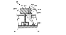
図3は、本発明の第1実施形態における設定装置の外観を説明する図である。図4は、本発明の第1実施形態における設定装置の断面構造(切断線A1-A2)を説明する図である。図3の説明においては、上述した定義によると、図上部が奥側に相当し、図下部が手前側に相当する。スライド操作子25は、略直方体形状を有し、遮光性を有する遮光部材251、253(第1部分)および透光性を有する透光部材252(第2部分)を含む。遮光部材251、253および透光部材252は、いずれも略直方体形状を有するが、別の形状であってもよい。遮光部材251、253および透光部材252は、いずれも樹脂で形成されているが、少なくとも一方が金属、セラミックス、ガラス等で形成されていてもよい。
FIG. 3 is a diagram illustrating the appearance of the setting device according to the first embodiment of the present invention. FIG. 4 is a diagram illustrating a cross-sectional structure (cutting line A1-A2) of the setting device according to the first embodiment of the present invention. In the description of FIG. 3, according to the above definition, the upper part of the figure corresponds to the back side, and the lower part of the figure corresponds to the front side. The
この例では、遮光部材251、透光部材252、遮光部材253の順に、左右方向に沿って並んでいる。透光部材252(誘導部)は、遮光部材251と遮光部材253とに挟まれ、スライド操作子25の下面SFb(第2面)から入射した光を下面SFbと対向する上面SFa(第1面)まで誘導する導光路LPを形成する。透光部材252はスライド方向に沿って長手を有するように配置され、この例では、スライド操作子25の手前側の端部から奥側の端部までの長手を有する。その結果、スライド操作子25は、遮光性を有する部分が透光性を有する部分によって2つの領域に区分された構造になっている。
In this example, the
支持棒27は、角柱状の部材であり、スライド操作子25とスライド機構24とをつなぐ部材である。支持棒27の一方の端部は遮光部材251の下面SFb側に接続されている。筐体95には、支持棒27が通過するためのスリット98が配置されている。スライド機構24は、プリント基板51上に配置され、スライド操作子25を移動領域MA(第1領域)内で移動可能に保持する機構を含む。移動領域MAのうち、最も奥側となるスライド操作子25の位置を後端位置BLといい、最も手前側となるスライド操作子25の位置を前端位置FLという。
The
指示位置検出部28は、プリント基板51上に配置され、スライド操作子25のスライド方向に沿った位置を検出し、上述したように前端位置FLと後端位置BLとの間を9段階に区分したときの位置を検出する。ここでは、指示位置表示部35は、スライド操作子25が後端位置BLにあるときに「0」の位置として検出し、前端位置FLにあるときに「8」の位置として検出する。図3に示す例では、スライド操作子25は、「4」の位置として検出される。
The designated
指示位置表示部35は、筐体95に配置されたいずれも略長方形の表示面35-1、35-2、・・・、35-8を含む。後端位置BL側から前端位置FL側に向かって、表示面35-1、35-2、・・・、35-8の順に並ぶ。表示面35-1、35-2、・・・、35-8のうち、スライド操作子25の指示位置の値に相当する数の表示面がスライド操作子25よりも奥側に配置されるように、スライド操作子25と指示位置表示部35との位置関係が規定されている。例えば、図3に示すように、スライド操作子25が「4」の位置に存在する場合には、表示面35-1~35-4までがスライド操作子25の奥側に配置された状態である。
The indicated
図3に示す例では、スライド操作子25より奥側にある表示面35-1~35-4が発光領域LAであり、表示面35-5~35-8が非発光領域DAである。すなわち、スライド操作子25の指示位置に対応する数の表示面が発光状態となって発光領域LAが形成される。なお、発光領域LAのうち、スライド操作子25が覆う表示面(この例では表示面35-5)と、最も奥側の表示面35-1との間の少なくとも1つの表示面が発光していれば、いずれかの表示面が発光していなくてもよい。
In the example shown in FIG. 3, the display surfaces 35-1 to 35-4 on the back side of the
一方、ユーザによって指示位置の設定を設定データに基づいて更新する指示が入力された場合には、スライド操作子25の位置とは関係なく表示面の発光が制御される。例えば、スライド操作子25の位置が図3に示す位置のままでも、表示面35-1~表示面35-8の全てが発光領域LAとなる場合もある。
On the other hand, when the user inputs an instruction to update the setting of the designated position based on the setting data, the light emission of the display surface is controlled regardless of the position of the
スライド操作子25は、前端位置FLに存在する場合を除き、表示面35-1~35-8の少なくとも一部を覆っている。表示面35-1~35-8のうち、スライド操作子25に覆われる可能性のある部分を重畳領域CA(第2領域)という。すなわち、スライド操作子25の移動範囲MAの少なくとも一部において、重畳領域CAの一部がスライド操作子25によって覆われる状態となる。この例では、スライド操作子25が表示面を覆っている状態では、スライド操作子25における左右方向の端部2515、2535のうち、端部2515のみ重畳領域CAの外側に配置される。したがって、端部2535側においては重畳領域CAのさらに外側においても、発光領域が存在する。
The
この例では、スライド操作子25が前端位置FLに存在する場合には、指示位置表示部35のいずれの表示面も覆わないため、以下のような構造になっているともいえる。スライド方向における重畳領域CAの長さは、移動領域MAの長さよりも短い。また、重畳領域CAの奥側の端部(第1端部)と移動領域MAにおける奥側の端部(第3端部)との距離は、重畳領域CAの手前側の端部(第2端部)と移動領域MAにおける手前側の端部(第4端部)との距離よりも短い。
In this example, when the
発光駆動部36は、発光制御信号PVに基づいて、発光素子38-1、38-2、・・・38-8を発光させる。発光素子38-1~38-8をそれぞれ区別して説明する必要がない場合には、単に発光素子38と記載する場合がある。発光素子38は、この例ではLEDである。以下、発光素子38の発光が表示面35に導かれる構造を説明する。図4に示すように、発光素子38-5と表示面35-5との間には、発光素子38-5が発生した光を表示面35-5に導くための導光部材37-5が配置されている。したがって、発光素子38-5が発光することによって、表示面35-5が発光したように見える。なお、導光部材37には、拡散板等の光拡散効果を有する部材、反射板等の光が外部に漏れないようにするための反射効果を有する部材などが用いられてもよい。これによって、発光素子38-5からの光が表示面35-5全体に拡がるように導かれる。
The light
表示面35-1、35-2、・・・、35-8とそれぞれに対応する発光素子38-1、38-2、・・・38-8との間には、導光部材37-1、37-2、・・・、37-8が配置されている。導光部材37-1~37-8をそれぞれ区別して説明する必要がない場合には、単に導光部材37と記載する場合がある。図3においては、図の複雑化を避けるため、導光部材37の図示を省略している。 A light guide member 37-1 is provided between the display surfaces 35-1, 35-2, ..., 35-8 and the corresponding light emitting elements 38-1, 38-2, ..., 38-8. , 37-2, . . . , 37-8 are arranged. When it is not necessary to separately explain the light guide members 37-1 to 37-8, they may be simply referred to as the light guide member 37. In FIG. 3, illustration of the light guide member 37 is omitted to avoid complication of the drawing.
スライド機構24が存在することによって、表示面35-5の直下に発光素子38-5が配置することが困難な場合がある。特に、表示面35-5のうち重畳領域CAの直下においては、スライド操作子25の下方にスライド機構24が存在しているために発光素子38-5を配置するスペースがない、また、スライド機構24に近い位置に発光素子38-5を配置しなくてはならないなど、スライド機構24の影響をより受けることになる。このような場合であっても、導光部材37-5の存在により、スライド機構24から離れた場所、すなわち、重畳領域CAの直下に相当しない場所に発光素子38-5を配置しても、重畳領域CAにおける表示面を発光させることができる。図3のようにスライド操作子25の上面SFa側から見た場合においては、発光素子38が重畳領域CAの外側に配置することもできる。なお、重畳領域CA内に発光素子38を配置するスペースがあれば、発光素子38を重畳領域CA内に配置してもよい。
Due to the presence of the
スライド操作子25と表示面35-1~35-8とによって重畳領域CAが形成されるようにそれぞれが配置されていることにより、スライド操作子25と指示位置表示部35との対応関係が明確になる。また、スライド操作子25をオルガン音色制御のためのドローバーとしての操作に使用した場合、重畳領域CAの奥側の端部(第1端部)からスライド操作子25まで、スライド操作子25のスライド操作に連動して拡がる発光領域LAにより、トーンホイール・オルガンのドローバーの構造や操作感を想起させることもできる。
By arranging the
一方、指示位置の設定が更新されて表示面35-5が発光した場合を想定する。表示面35-5はスライド操作子25によって覆われているため、仮にスライド操作子25が透光部材252を有しない場合には、表示面35-1~35-5が発光しているのか、表示面35-1~35-4が発光している(表示面35-5が非発光状態)のか、が一見してわかりにくい。スライド操作子25が透光部材252を有することにより、表示面35-5からの光は、スライド操作子25における透光部材252によって下面SFbから上面SFaに導かれる。したがって、スライド操作子25の外面側から、スライド操作子25に覆われた表示面35-5の表示を明瞭に視認することができる。
On the other hand, assume that the setting of the indicated position is updated and the display surface 35-5 emits light. Since the display surface 35-5 is covered by the
なお、仮にこの透光部材252が存在しない場合であっても、この例によれば、表示面35-5のうち重畳領域CAに含まれない領域、すなわち、スライド操作子25に覆われていない領域が存在するため、その領域から表示面35-5が発光しているか否かを確認することはできる。したがって、透光部材252が存在しなくてもよいが、透光部材252がある場合よりは視認性が低下するため、透光部材252が存在することが望ましい。
Note that even if this
[3.音制御機能の構成]
続いて、制御部10において実現される音制御機能100について図5を用いて説明する。
[3. Sound control function configuration]
Next, the
図5は、本発明の第1実施形態における音制御機能を説明する図である。制御部10は、制御プログラムを実行すると、電子鍵盤装置1において音制御機能100を実現する。音制御機能100を実現する構成は、操作値SV取得部110、パラメータ出力部130、再生制御部150、設定登録部170および設定更新部190を含む。なお、これらの構成は、全てソフトウェアによって実現されてもよいし、少なくとも一部がハードウェアによって実現されてもよい。
FIG. 5 is a diagram illustrating the sound control function in the first embodiment of the present invention. When the
操作値SV取得部110は、操作値SaV~SiVを取得すると、パラメータ出力部130に供給する。スライド操作子25の指示位置が変更される度に、操作値SV取得部110によって操作値SVが取得される。
When the operation value
パラメータ出力部130は、スライド操作子25a~25iのそれぞれの指示位置を取得する。パラメータ出力部130は、最後に取得したスライド操作子25の指示位置をバッファし、新たに取得する度にバッファされている指示位置を更新し、その指示位置に応じたパラメータ値(この例では、制御対象の倍音の成分量に対応する値)Cpを再生制御部150に出力する。このように、パラメータ出力部130は、入力された指示に基づいて、音を制御するためのパラメータ値を設定している。
The
さらに、パラメータ出力部130は、スライド操作子25(25a~25i)のそれぞれの指示位置に応じて、指示位置表示部35(35a~35i)を表示させるための発光制御信号PV(PaV~PiV)を出力する。この例では、図3において説明したように、指示位置表示部35の表示面35-1~35-8のうち、スライド操作子25よりも奥側にある表示面が発光表示されるように発光制御信号PVが出力される。パラメータ出力部130は、後述する設定更新部190によってバッファされた指示位置が更新された場合にも、操作値SV取得部110から操作値SVを取得したときと同様にパラメータ値Cpと発光制御信号PVとを送信する。
Further, the
設定登録部170は、スライド操作子25の指示位置の設定を登録する指示を示す操作信号Ssを取得すると、パラメータ出力部130にバッファされたスライド操作子25の指示位置を読み出して、設定データ記憶領域181に設定データとして登録する。
When the setting
設定更新部190は、スライド操作子25の指示位置の設定を更新する指示を示す操作信号Ssを取得すると、設定データ記憶領域181から設定データを読み出して、パラメータ出力部130にバッファされた指示位置を更新する。
When the
再生制御部150は、検出信号KVを取得すると、検出信号KVに基づいて発生すべき音信号も音源部40において生成させるように音源制御信号Ctを生成する。この検出信号KVは、パラメータ出力部130から出力されたパラメータ値Cpにより、検出信号KVに基づく音信号についても変更されるように音源制御信号Ctが出力される。以上が、音制御機能100についての説明である。
Upon acquiring the detection signal KV, the
[4.指示位置表示部35の表示例]
続いて、指示位置表示部35における表示例、および指示値の設定が更新された場合の変更例について説明する。ここでは、指示位置の設定登録、設定の変更、設定の更新の順に処理を進めた場合における指示位置表示部35の表示の変化について説明する。
[4. Display example of indicated position display section 35]
Next, a display example on the designated
図6は、本発明の第1実施形態におけるスライド操作子と発光範囲との関係(設定登録時)を説明する図である。図6においては、スライド操作子25a~25iの指示位置が、順に「6」、「8」、「6」、「5」、「3」、「5」、「4」、「5」、「5」である。指示位置表示部35a~35iは、この指示位置に対応して発光する。すなわち、一番奥側の表示面35-1からスライド操作子25の指示位置に相当する数までの表示面が発光する。図3の例によれば、スライド操作子25の指示値が「4」であり、表示面35-1~35-4の4個の表示面が発光する。図6に示された状態において、スライド操作子25の指示位置の設定を登録する指示が操作部70に入力されたものとする。これによって設定データ記憶領域181に上述したスライド操作子25a~25iの指示位置が設定データとして登録される。
FIG. 6 is a diagram illustrating the relationship between the slide operator and the light emitting range (at the time of setting registration) in the first embodiment of the present invention. In FIG. 6, the indicated positions of the
図6に示すように、隣接するスライド操作子25が近い状態であっても、対応関係にあるスライド操作子25と指示位置表示部35とが重なっている部分を有するため、ユーザはスライド操作子25と指示位置表示部35との対応関係を明瞭に視認することができる。また、発光範囲が一番奥側の表示面からスライド操作子25まで連なる状態になるため、ユーザはトーンホイール・オルガンのドローバーを引き出すときの状態に近い感覚で設定値を視認することができる。
As shown in FIG. 6, even if
図7は、本発明の第1実施形態におけるスライド操作子と発光範囲との関係(設定変更時)を説明する図である。図7は、図6に示す状態において、ユーザがスライド操作子25を動かして指示位置を変更した例である。図7においては、スライド操作子25a~25iの指示位置が、順に「8」、「4」、「6」、「0」、「7」、「2」、「6」、「7」、「4」である。指示位置表示部35a~35iは、この指示位置に対応して発光する。このように、設定値に応じて指示位置表示部35~35iの発光範囲が変化する。また、出力される音色も、図7に示す指示位置に応じた音色に変更される。
FIG. 7 is a diagram illustrating the relationship between the slide operator and the light emitting range (when changing settings) in the first embodiment of the present invention. FIG. 7 shows an example in which the user moves the
図8は、本発明の第1実施形態におけるスライド操作子と発光範囲との関係(設定更新時)を説明する図である。図8は、図7に示す状態において、スライド操作子25の指示位置の設定を更新する指示が操作部70に入力された例である。ここで読み出される設定データは、図6において登録された設定データである。したがって、図8においては、スライド操作子25の指示位置が図7に示すものである一方、指示位置表示部35の発光範囲が図6に示すものとなっている。また、出力される音色は、図7に示すスライド操作子25の指示位置ではなく、図6に示す指示位置に応じた音色に変更される。
FIG. 8 is a diagram illustrating the relationship between the slide operator and the light emitting range (when updating settings) in the first embodiment of the present invention. FIG. 8 shows an example in which an instruction to update the setting of the designated position of the
指示位置表示部35aにおいては、表示面35a-1~35a-6が発光している。スライド操作子25aは指示位置「8」に配置されているため、発光範囲がスライド操作子25aによって覆われていない。したがって、ユーザは、更新後におけるスライド操作子25aに対応する設定値が「6」に更新されたことを容易に視認することができる。
In the designated
指示位置表示部35iにおいては、表示面35i-1~35i-5が発光している。スライド操作子25iは指示位置「5」に配置されているため、発光範囲の一部(表示面35i-5)がスライド操作子25iによって覆われている。この状態であっても、表示面35i-5の発光範囲のうち、一部の範囲の光がスライド操作子25iの透光部分を通過する。したがって、ユーザは、スライド操作子25iに対応する設定値が「5」であることを容易に視認することができる。
In the designated
一方、仮に、スライド操作子25iの透光部分がない場合、発光範囲のうちスライド操作子25iによって覆われていない部分の表示面35i-5しか視認できず、設定値が「5」であるのか「4」であるのかを確認するときの視認性が低い。また、後述する実施形態のように操作子の形状によっては、スライド操作子25iが表示面35i-5を完全に覆うため、例えば、表示面35i-5が発光しているのかどうかを視認することができない。
On the other hand, if there is no transparent part of the
また、指示位置表示部35fにおいては、表示面35f-1~35f-5が発光している。スライド操作子25fは指示位置「2」に配置されているため、発光範囲の一部(表示面35f-3、35f-4)がスライド操作子25fによって覆われている。一方、表示面35f-5がスライド操作子25fによって覆われていないため、設定値が「5」であることは視認できる。ここで、表示面35f-3、35f-4の発光範囲のうち、一部の光がスライド操作子25fの透光部分を通過する。したがって、表示面35f-1~35f-5までの発光が連なった状態になるため、スライド操作子25fが指示位置「5」に配置されていなくても、ユーザは読み出された設定データが「5」であることを視認することができるとともに、ドローバーを引き出したときの状態に近い外観も維持される。
Further, in the designated
なお、この状態でスライド操作子25を操作すると、その指示位置に対応するように発光範囲が変化する。この変化は、操作対象のスライド操作子25に対応する指示位置表示部35の発光範囲が変化するものであってもよい。例えば、スライド操作子25fを移動させたときに、スライド操作子25fに対応する指示位置のみが変更され、その指示位置に対応して指示位置表示部35fのみの発光範囲が変化してもよい。また、この変化は、全てのスライド操作子25に対応する指示位置表示部35の発光範囲が変化してもよい。例えば、スライド操作子25fの指示位置を変更したときに、全てのスライド操作子25a~25iの指示位置も併せて変更され、それらの指示位置に対応して指示位置表示部35a~35iの発光範囲が変化してもよい。
Note that when the
上述したように、スライド操作子25と指示位置表示部35の表示面との関係において重畳領域CAを有することによって、ユーザは双方の対応関係を容易に認識することができる。また、スライド操作子25のうち重畳領域CAの少なくとも一部に透光部分が設けられることにより、指示位置表示部35における発光が重畳領域CAにおいてスライド操作子25に覆われていたとしても、スライド操作子25の外面側に光を導き、ユーザに視認させることができる。また、スライド操作子25の全てが透光部材で形成される場合に比べ、遮光部材と透光部材とを組み合わせることにより、さらには、透光部材を遮光部材で挟むように配置することにより、スライド操作子25そのものの視認性を向上させることもできる。
As described above, by having the overlapping area CA in the relationship between the
<第2実施形態>
第2実施形態では、スライド操作子25における左右方向の端部2515、2535のうち、いずれの端部2515、2535についても重畳領域CAの外側に配置される指示位置表示部35Aを有する発光部30Aを含む設定装置2Aについて説明する。
<Second embodiment>
In the second embodiment, the
図9は、本発明の第2実施形態における設定装置の外観を説明する図である。図10は、本発明の第2実施形態における設定装置の断面構造を説明する図である。指示位置表示部35Aは、第1実施形態における指示位置表示部35に比べて各表示面の左右方向の幅が狭い。そのため、導光部材37Aは、第1実施形態における導光部材37とは形状が異なっている。
FIG. 9 is a diagram illustrating the appearance of a setting device according to the second embodiment of the present invention. FIG. 10 is a diagram illustrating a cross-sectional structure of a setting device according to a second embodiment of the present invention. In the designated
この例では、スライド操作子25の端部2515、2535のいずれも重畳領域CAの外側に配置される。したがって、図9に示すように、スライド操作子25が指示位置「4」に配置されている場合には、表示面35A-5は、完全にスライド操作子25に覆われる。このようなスライド操作子25と指示位置表示部35Aとの位置関係であっても、表示面35A-5が発光した場合には透光部材252が導光路LPとなって、その発光をスライド操作子25の外面側から視認することができる。
In this example, both ends 2515 and 2535 of the
<第3実施形態>
第3実施形態では、スライド操作子25の指示位置に対応した表示面のみが発光する指示位置表示部35Bを含む設定装置2Bについて説明する。
<Third embodiment>
In the third embodiment, a
図11は、本発明の第3実施形態における設定装置の外観を説明する図である。この例では、指示位置表示部35Bのうち、スライド操作子25が覆う表示面(図11の例では、表示面35B-4)のみが発光する。なお、表示面35B-4に隣接する表示面についても表示されてもよい。また、スライド操作子25が覆っていない表示面の1つ(例えば、スライド操作子25の奥側の表示面)が発光してもよい。このように、最も奥側に配置された表示面35B-1から連なった発光範囲が形成されない場合もある。
FIG. 11 is a diagram illustrating the appearance of a setting device according to the third embodiment of the present invention. In this example, of the designated
<第4実施形態>
第4実施形態では、互いに分離された表示面ではなく、連続した表示面を含む指示位置表示部35Cを含む設定装置2Cについて説明する。
<Fourth embodiment>
In the fourth embodiment, a
図12は、本発明の第4実施形態における設定装置の外観を説明する図である。指示位置表示部35Cは、例えば、液晶ディスプレイ、有機ELディスプレイなど、連続的に発光範囲を変化させることができる表示面を含む。この場合には、導光部材37および発光素子38は不要であり、発光駆動部36によって指示位置表示部35Cの表示内容が制御される。
FIG. 12 is a diagram illustrating the appearance of a setting device according to the fourth embodiment of the present invention. The designated
指示位置表示部35Cの奥側の端部35C-1と手前側の端部35C-2の間において、発光範囲が変化する。この例では、スライド操作子25の指示位置を境界LBとして、端部35C-1側に発光領域LAが配置され、端部35C-2側に非発光領域DAが配置されている。この例では、境界LBは、スライド操作子25における奥側の端部の位置とほぼ一致しているが、第3実施形態で示したように、スライド操作子25の略中央部分に位置するように設定されてもよい。
The light emitting range changes between the
このように発光範囲を連続的に変化できるようにすると、スライド操作子25の指示位置を128段階で区分するような場合であっても、指示位置表示部35Cにおいて精度よく指示位置を表示することができる。なお、指示位置が128段階に区分されてパラメータ値Cpが制御されたとしても、スライド操作子25の位置をより高分解能で取得することで、指示位置表示部35Cの発光範囲の変化が128段階以上に細かく変化するようになっていてもよい。
By making it possible to change the light emitting range continuously in this way, even when the indicated position of the
<第5実施形態>
第5実施形態では、透光部材252に代えて貫通孔により導光路LPが形成されるスライド操作子25Dを含む設定装置2Dについて説明する。
<Fifth embodiment>
In the fifth embodiment, a
図13は、本発明の第5実施形態における設定装置の外観を説明する図である。図14は、本発明の第5実施形態における設定装置の断面構造を説明する図である。スライド操作子25Dには、上面SFaと下面SFbとの間を貫通する貫通孔252Dが設けられている。ユーザは、貫通孔252Dを通して表示面(図13の例では表示面35-5)を直接視認することができる。このように、スライド操作子のうち導光路LPとなる部分は、透光部材を用いる場合に限らず、空間により形成されてもよい。この空間は、1つの貫通孔で実現される場合に限らず、メッシュ状の構造体で実現されてもよいし、複数の貫通孔を用いて実現されてもよい。
FIG. 13 is a diagram illustrating the appearance of a setting device according to the fifth embodiment of the present invention. FIG. 14 is a diagram illustrating a cross-sectional structure of a setting device according to a fifth embodiment of the present invention. The
<第6実施形態>
第6実施形態では、曲がっている導光路LPが設けられたスライド操作子25Eを含む設定装置2Eについて説明する。
<Sixth embodiment>
In the sixth embodiment, a setting device 2E including a
図15は、本発明の第6実施形態における設定装置の断面構造を説明する図である。スライド操作子25Eは、遮光部材251Eと遮光部材253Eとに挟まれた透光部材252Eを含む。透光部材252Eは、曲面の表面形状を有し、下面SFbに露出した部分と上面SFaに露出した部分とが左右方向にずれている。透光部材252Eがこのような構成を有する場合には、表示面からの光が下面SFbから上面SFaへ効率よく導かれるように、透光部材252Eと遮光部材251E、253Eとの界面に反射材を設けたり、透光部材252Eに光拡散材料を設けたりしてもよい。
FIG. 15 is a diagram illustrating a cross-sectional structure of a setting device according to a sixth embodiment of the present invention. The
また、透光部材252Eは、下面SFbに露出した部分の面積と、上面SFaに露出した部分の面積とが異なっていてもよい。要求される視認性によって、下面SFb側の面積を大きくしてもよいし、上面SFa側の面積を大きくしてもよい。
Furthermore, the area of the portion of the light-transmitting
<第7実施形態>
第7実施形態では、スライド操作子ではなくロータリエンコーダなどの回転操作子25Fを含む設定装置2Fについて説明する。
<Seventh embodiment>
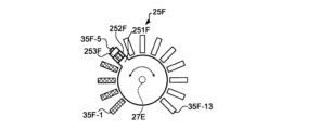
In the seventh embodiment, a setting device 2F including a
図16は、本発明の第7実施形態における操作子と発光範囲との関係(設定変更時)を説明する図である。回転操作子25Fは、軸27Eを中心に回転する。回転操作し25Fは、遮光部材251F、253Fおよび透光部材252Fを含む。遮光部材251Fは略円柱形状を有し、円柱側面から突出する部分を含む。この突出する部分に透光部材252Fが接続されている。透光部材252Fは、遮光部材251Fと遮光部材253Fとに挟まれている。
FIG. 16 is a diagram illustrating the relationship between the operator and the light emitting range (when changing settings) in the seventh embodiment of the present invention.
透光部材252Fおよび遮光部材253Fが配置された部分が回転操作子25Fの指示位置を規定する。この例では、回転操作子25Fは、指示位置「0」~「12」のいずれかを指すように回転する。指示位置「0」~「12」は、それぞれ表示面35F-1~35F13に対応する。図16に示す例では、回転操作子25Fは指示位置「4」を示し、その指示位置に応じた表示面35F-1~35F-5が発光している。この状態においても表示面35F-5からの光の一部分は、透光部材252Fを通過することによって回転操作子25Fの外面側から視認可能である。
The portion where the light-transmitting
図17は、本発明の第7実施形態における操作子と発光範囲との関係(設定更新時)を説明する図である。設定の更新指示により指示位置「8」に設定値が更新されると、表示面35F-1~35F-9が発光するように発光範囲が変化する。回転操作子25Fをさらに回転させるまでは図17の状態が維持される。
FIG. 17 is a diagram illustrating the relationship between the operator and the light emitting range (when updating settings) in the seventh embodiment of the present invention. When the set value is updated to the designated position "8" by the setting update instruction, the light emitting range changes so that the display surfaces 35F-1 to 35F-9 emit light. The state shown in FIG. 17 is maintained until the
<変形例>
以上、本発明の一実施形態について説明したが、本発明の一実施形態は、以下のように様々な形態に変形することもできる。また、上述した実施形態および以下に説明する変形例は、それぞれ互いに組み合わせて適用することもできる。さらに、各実施形態の構成の一部について、他の構成の追加・削除・置換をすることが可能である。以下の説明では第1実施形態を変形した例として説明するが、他の実施形態を変形する例として適用することもできる。
<Modified example>
Although one embodiment of the present invention has been described above, one embodiment of the present invention can also be modified into various forms as described below. Further, the embodiments described above and the modified examples described below can be applied in combination with each other. Furthermore, it is possible to add, delete, or replace some of the configurations of each embodiment with other configurations. In the following description, the first embodiment will be described as a modified example, but other embodiments can also be applied as modified examples.
(1)指示位置表示部35の表示面の発光色は、設定により変更できるようになっていてもよい。発光色は、パラメータ設定値に応じて変更されてもよいし、表示面毎に異ならせてもよい。また、指示位置表示部35のいずれかが、他と異なる色を有していてもよい。また、2段の鍵盤を有するトーンホイール・オルガンにおけるドローバーのようにスライド操作子25を利用する場合には、上段の鍵盤に対する設定をする場合と下段の鍵盤に対する設定をする場合とで発光色が異なるようにしてもよい。
(1) The color of the light emitted from the display surface of the indicated
(2)表示面35-1~35-8は、長方形以外の形状であってもよいし、文字の形状を有していてもよい。また、表示面35-1~35-8のいずれかが、他と異なる形状を有していてもよい。 (2) The display surfaces 35-1 to 35-8 may have a shape other than a rectangle or may have a character shape. Further, any one of the display surfaces 35-1 to 35-8 may have a shape different from the others.
(3)スライド操作子25に用いられる透光部材252は、スライド操作子25の手前側の端部から奥側の端部までつながっていなくてもよい。この場合には、遮光部材251と遮光部材253とが一体の構造体であってもよい。
(3) The light-transmitting
(4)スライド操作子25において遮光部材253が存在しなくてもよい。この場合には、遮光部材251と透光部材252とが接続され、左右方向におけるスライド操作子25の両端部の一方が透光部材252からなり、他方が遮光部材251からなる。
(4) The
1…電子鍵盤装置、2…設定装置、10…制御部、18…記憶部、20…入力装置、24…スライド機構、25…スライド操作子、25F…回転操作子、27…支持棒、27E…軸、28…指示位置検出部、30…発光装置、35…指示位置表示部、35-1~35-8…表示面、35C-1,35C-2…端部、36…発光駆動部、37…導光部材、38…発光素子、40…音源部、50…表示部、51…プリント基板、60…スピーカ、65…信号出力部、70…操作部、80…鍵盤部、88…押鍵検出部、90…インターフェース、95…筐体、98…スリット、100…音制御機能、110…取得部、130…パラメータ出力部、150…再生制御部、170…設定登録部、181…設定データ記憶領域、190…設定更新部、251…遮光部材、252…透光部材、252D…貫通孔、2515,2535…端部
DESCRIPTION OF
Claims (9)
前記第1領域内に前記設定値に応じて発光範囲が変化する第2領域を有し、前記操作子によって前記第2領域の一部が覆われる発光部と、
を備え、
前記操作子の移動と前記発光範囲の変化とが対応している、設定装置。 an operator for specifying a setting value of the first parameter by moving within the first area;
a light-emitting section having a second region whose light-emitting range changes according to the set value in the first region, and a part of the second region being covered by the operator;
Equipped with
A setting device in which a movement of the operator corresponds to a change in the light emitting range .
前記発光範囲は、前記第1方向に沿って変化し、
前記誘導部は、前記操作子の外面のうち前記第1方向に長手を有する範囲に前記光を誘導する、請求項2に記載の設定装置。 The first region is a region having a longitudinal direction in a first direction,
The light emitting range varies along the first direction,
The setting device according to claim 2, wherein the guide section guides the light to a range of an outer surface of the operator that has a longitudinal direction in the first direction.
前記第1端部と前記第3端部との距離は、前記第2端部と前記第4端部との距離よりも短く、
前記発光範囲は、前記第2領域のうち前記操作部に覆われた部分と前記第1端部との間の少なくとも一部を含む、請求項3に記載の設定装置。 The length from the first end to the second end of the second region in the first direction is shorter than the length from the third end to the fourth end of the first region in the first direction. ,
The distance between the first end and the third end is shorter than the distance between the second end and the fourth end,
The setting device according to claim 3, wherein the light emitting range includes at least a portion of the second region between a portion covered by the operation section and the first end.
前記第2領域の外側に前記発光素子が配置されている、請求項1から請求項6のいずれかに記載の設定装置。 The light emitting unit includes a light emitting element and a member that guides light generated by the light emitting element to the second region,
The setting device according to any one of claims 1 to 6, wherein the light emitting element is arranged outside the second region.
遮光性を有する第1部分と、
前記操作子の第1面から前記第1面と対向する第2面までの透光性を有する第2部分と、
を含む、操作子。 An operator for specifying a setting value of a first parameter related to sound by moving within a first area with respect to the housing,
a first portion having light blocking properties;
a second portion having translucency from a first surface of the operator to a second surface opposite to the first surface;
Controls, including:
Priority Applications (4)
| Application Number | Priority Date | Filing Date | Title |
|---|---|---|---|
| JP2019225847A JP7396014B2 (en) | 2019-12-13 | 2019-12-13 | Setting device and controls |
| DE102020215107.5A DE102020215107B4 (en) | 2019-12-13 | 2020-12-01 | ADJUSTMENT DEVICE, ACTUATOR AND ADJUSTMENT METHOD |
| US17/108,328 US11646006B2 (en) | 2019-12-13 | 2020-12-01 | Setting device, operating element and setting method |
| CN202011398557.7A CN112992105B (en) | 2019-12-13 | 2020-12-02 | Setting device and operating member |
Applications Claiming Priority (1)
| Application Number | Priority Date | Filing Date | Title |
|---|---|---|---|
| JP2019225847A JP7396014B2 (en) | 2019-12-13 | 2019-12-13 | Setting device and controls |
Publications (2)
| Publication Number | Publication Date |
|---|---|
| JP2021096532A JP2021096532A (en) | 2021-06-24 |
| JP7396014B2 true JP7396014B2 (en) | 2023-12-12 |
Family
ID=76085513
Family Applications (1)
| Application Number | Title | Priority Date | Filing Date |
|---|---|---|---|
| JP2019225847A Active JP7396014B2 (en) | 2019-12-13 | 2019-12-13 | Setting device and controls |
Country Status (4)
| Country | Link |
|---|---|
| US (1) | US11646006B2 (en) |
| JP (1) | JP7396014B2 (en) |
| CN (1) | CN112992105B (en) |
| DE (1) | DE102020215107B4 (en) |
Families Citing this family (3)
| Publication number | Priority date | Publication date | Assignee | Title |
|---|---|---|---|---|
| JP7396014B2 (en) * | 2019-12-13 | 2023-12-12 | ヤマハ株式会社 | Setting device and controls |
| JP2023122459A (en) * | 2022-02-22 | 2023-09-01 | ヤマハ株式会社 | Input devices and electronic musical instruments |
| JP7528986B2 (en) * | 2022-06-17 | 2024-08-06 | カシオ計算機株式会社 | Electronic musical instrument, light emission control method and program |
Citations (3)
| Publication number | Priority date | Publication date | Assignee | Title |
|---|---|---|---|---|
| JP2009244924A (en) | 2008-03-28 | 2009-10-22 | Yamaha Corp | Electronic apparatus |
| JP2009260259A (en) | 2008-03-25 | 2009-11-05 | Yamaha Corp | Slide manipulation device and slide control panel |
| WO2016166793A1 (en) | 2015-04-13 | 2016-10-20 | 三菱電機株式会社 | Operating tool, input device, and electronic device |
Family Cites Families (31)
| Publication number | Priority date | Publication date | Assignee | Title |
|---|---|---|---|---|
| JPS58101429U (en) * | 1981-12-28 | 1983-07-09 | 株式会社小糸製作所 | display device |
| JPS593504U (en) * | 1982-06-29 | 1984-01-11 | 三菱電機株式会社 | Slide type volume display device |
| JPS6027408U (en) * | 1983-08-01 | 1985-02-25 | アルプス電気株式会社 | Illuminated sliding variable resistor |
| JPH01151810A (en) * | 1988-10-26 | 1989-06-14 | Alpine Electron Inc | Equalizer device |
| JPH05283957A (en) * | 1992-04-02 | 1993-10-29 | Sony Corp | Variable resistor |
| JP2002049301A (en) * | 2000-08-01 | 2002-02-15 | Kawai Musical Instr Mfg Co Ltd | Key press display device, electronic musical instrument system, key press display method, and storage medium |
| US20060191401A1 (en) * | 2003-04-14 | 2006-08-31 | Hiromu Ueshima | Automatic musical instrument, automatic music performing method and automatic music performing program |
| CN1892525B (en) * | 2005-07-04 | 2010-08-18 | 雅马哈株式会社 | Slide operation device |
| JP2007248741A (en) * | 2006-03-15 | 2007-09-27 | Kawai Musical Instr Mfg Co Ltd | Operating device and electronic musical instrument |
| JP2008116760A (en) * | 2006-11-06 | 2008-05-22 | Yamaha Corp | Electronic musical device |
| JP5119656B2 (en) * | 2006-12-13 | 2013-01-16 | ヤマハ株式会社 | Electronic musical instrument keyboard device |
| JP5292964B2 (en) * | 2008-07-16 | 2013-09-18 | ヤマハ株式会社 | Translucent operation unit |
| CN101329863B (en) * | 2008-07-18 | 2012-08-22 | 武汉艾立卡电子有限公司 | Photoelectric control transposer for electric guitar |
| JP2013080572A (en) * | 2011-10-03 | 2013-05-02 | Nihon Kaiheiki Industry Co Ltd | Illumination-type push button switch and display device |
| US9196236B1 (en) | 2014-09-02 | 2015-11-24 | Native Instruments Gmbh | Electronic music instrument, system and method for operating an electronic music instrument |
| EP3237250B1 (en) * | 2014-12-22 | 2020-04-22 | Volkswagen AG | Finger-operated control bar, and use of said control bar |
| US9665262B2 (en) * | 2015-03-06 | 2017-05-30 | Cooper Technologies Company | Active preview control faders |
| JP6634687B2 (en) | 2015-03-17 | 2020-01-22 | ヤマハ株式会社 | Level control device |
| CN104991319B (en) * | 2015-06-01 | 2019-03-26 | 东莞市长资实业有限公司 | Switch module for controlling and adjusting photoelectric signal for input equipment |
| JP6524940B2 (en) * | 2016-03-01 | 2019-06-05 | ヤマハ株式会社 | Detection device and program |
| JP6638624B2 (en) * | 2016-11-10 | 2020-01-29 | ヤマハ株式会社 | Keyboard instrument |
| JP6519959B2 (en) * | 2017-03-22 | 2019-05-29 | カシオ計算機株式会社 | Operation processing apparatus, reproduction apparatus, operation processing method and program |
| US10732676B2 (en) * | 2017-09-06 | 2020-08-04 | Apple Inc. | Illuminated device enclosure with dynamic trackpad |
| GB201808694D0 (en) * | 2018-05-28 | 2018-07-11 | Spark And Rocket Ltd | Signalling apparatus and associated methods |
| CN208847290U (en) * | 2018-09-29 | 2019-05-10 | 西安冰峰饮料有限责任公司 | Multi-functional lamp inspection desk |
| CN113287371B (en) * | 2019-01-21 | 2024-06-18 | 昕诺飞控股有限公司 | Dynamic User Interface |
| DE102019204046B4 (en) * | 2019-03-25 | 2021-07-15 | Volkswagen Aktiengesellschaft | Device and method for outputting a parameter value in a vehicle |
| US11120781B2 (en) * | 2019-11-15 | 2021-09-14 | Inmusic Brands, Inc. | System and method for a visualizing characteristics of an audio event |
| JP7396014B2 (en) * | 2019-12-13 | 2023-12-12 | ヤマハ株式会社 | Setting device and controls |
| JP7419903B2 (en) * | 2020-03-18 | 2024-01-23 | ヤマハ株式会社 | Parameter control device, parameter control method and program |
| JP7212850B2 (en) * | 2020-12-09 | 2023-01-26 | カシオ計算機株式会社 | Switch devices and electronic devices |
-
2019
- 2019-12-13 JP JP2019225847A patent/JP7396014B2/en active Active
-
2020
- 2020-12-01 US US17/108,328 patent/US11646006B2/en active Active
- 2020-12-01 DE DE102020215107.5A patent/DE102020215107B4/en active Active
- 2020-12-02 CN CN202011398557.7A patent/CN112992105B/en active Active
Patent Citations (4)
| Publication number | Priority date | Publication date | Assignee | Title |
|---|---|---|---|---|
| JP2009260259A (en) | 2008-03-25 | 2009-11-05 | Yamaha Corp | Slide manipulation device and slide control panel |
| JP2009244924A (en) | 2008-03-28 | 2009-10-22 | Yamaha Corp | Electronic apparatus |
| WO2016166793A1 (en) | 2015-04-13 | 2016-10-20 | 三菱電機株式会社 | Operating tool, input device, and electronic device |
| US20180024649A1 (en) | 2015-04-13 | 2018-01-25 | Mitsubishi Electric Corporation | Operating tool, input device, and electronic device |
Also Published As
| Publication number | Publication date |
|---|---|
| US11646006B2 (en) | 2023-05-09 |
| JP2021096532A (en) | 2021-06-24 |
| US20210183346A1 (en) | 2021-06-17 |
| CN112992105B (en) | 2024-04-19 |
| DE102020215107B4 (en) | 2024-07-25 |
| CN112992105A (en) | 2021-06-18 |
| DE102020215107A1 (en) | 2021-06-17 |
Similar Documents
| Publication | Publication Date | Title |
|---|---|---|
| JP7396014B2 (en) | Setting device and controls | |
| EP2786370B1 (en) | Systems and methods of note event adjustment | |
| US7394010B2 (en) | Performance apparatus and tone generation method therefor | |
| JP2024052929A (en) | Performance operation device | |
| JP7156470B2 (en) | Controllers and electronic musical instruments | |
| US20200211519A1 (en) | Electronic musical instrument | |
| JP2010204401A (en) | Electronic musical instrument | |
| US8716587B2 (en) | Musical instruments | |
| WO2018079668A1 (en) | Keyboard device | |
| US20210151015A1 (en) | System and method for a visualizing characteristics of an audio event | |
| JP5771394B2 (en) | Music control device | |
| US8878044B2 (en) | Processing device and method for displaying a state of tone generation apparatus | |
| JP5803705B2 (en) | Electronic musical instruments | |
| JPH11338470A (en) | Electronic musical instrument and electronic musical instrument control method | |
| JP4613854B2 (en) | Performance equipment | |
| JP7788694B2 (en) | Electronic musical instrument control device | |
| US9183820B1 (en) | Electronic music instrument and method for controlling an electronic music instrument | |
| JP5825056B2 (en) | Electronic musical instruments | |
| JP7007533B2 (en) | Stringed instrument pseudo-sound generator, and stringed instrument pseudo-sound generator | |
| Vogels | Harmonica-inspired digital musical instrument design based on an existing gestural performance repertoire | |
| JP6544085B2 (en) | Parameter setting device, sound signal generation device, electronic musical instrument and program | |
| WO2025046682A1 (en) | Performance input device and performance input method | |
| JP2024103177A (en) | Tone setting program, tone setting device, and tone setting method | |
| JP2007156370A (en) | Electronic musical instrument with real image displayed in space as input index | |
| JP2024043174A (en) | Performance system, control system and control method |
Legal Events
| Date | Code | Title | Description |
|---|---|---|---|
| A621 | Written request for application examination |
Free format text: JAPANESE INTERMEDIATE CODE: A621 Effective date: 20221020 |
|
| A977 | Report on retrieval |
Free format text: JAPANESE INTERMEDIATE CODE: A971007 Effective date: 20230517 |
|
| A131 | Notification of reasons for refusal |
Free format text: JAPANESE INTERMEDIATE CODE: A131 Effective date: 20230620 |
|
| A521 | Request for written amendment filed |
Free format text: JAPANESE INTERMEDIATE CODE: A523 Effective date: 20230724 |
|
| TRDD | Decision of grant or rejection written | ||
| A01 | Written decision to grant a patent or to grant a registration (utility model) |
Free format text: JAPANESE INTERMEDIATE CODE: A01 Effective date: 20231031 |
|
| A61 | First payment of annual fees (during grant procedure) |
Free format text: JAPANESE INTERMEDIATE CODE: A61 Effective date: 20231113 |
|
| R151 | Written notification of patent or utility model registration |
Ref document number: 7396014 Country of ref document: JP Free format text: JAPANESE INTERMEDIATE CODE: R151 |
|
| S531 | Written request for registration of change of domicile |
Free format text: JAPANESE INTERMEDIATE CODE: R313532 |
|
| R350 | Written notification of registration of transfer |
Free format text: JAPANESE INTERMEDIATE CODE: R350 |