JP7388030B2 - vehicle shutter device - Google Patents
vehicle shutter device Download PDFInfo
- Publication number
- JP7388030B2 JP7388030B2 JP2019137737A JP2019137737A JP7388030B2 JP 7388030 B2 JP7388030 B2 JP 7388030B2 JP 2019137737 A JP2019137737 A JP 2019137737A JP 2019137737 A JP2019137737 A JP 2019137737A JP 7388030 B2 JP7388030 B2 JP 7388030B2
- Authority
- JP
- Japan
- Prior art keywords
- frame
- heat exchanger
- heat exchange
- protrusion
- exchange core
- Prior art date
- Legal status (The legal status is an assumption and is not a legal conclusion. Google has not performed a legal analysis and makes no representation as to the accuracy of the status listed.)
- Active
Links
- 239000012530 fluid Substances 0.000 claims description 19
- 239000000498 cooling water Substances 0.000 claims description 13
- 238000005057 refrigeration Methods 0.000 claims description 4
- 238000002485 combustion reaction Methods 0.000 claims description 3
- 238000011144 upstream manufacturing Methods 0.000 claims description 3
- 239000003990 capacitor Substances 0.000 description 23
- 239000003507 refrigerant Substances 0.000 description 14
- 238000003780 insertion Methods 0.000 description 5
- 230000037431 insertion Effects 0.000 description 5
- 230000000903 blocking effect Effects 0.000 description 4
- 239000007788 liquid Substances 0.000 description 4
- 239000007791 liquid phase Substances 0.000 description 4
- 238000005192 partition Methods 0.000 description 4
- 230000000694 effects Effects 0.000 description 3
- 230000007423 decrease Effects 0.000 description 2
- 238000005452 bending Methods 0.000 description 1
- 238000010586 diagram Methods 0.000 description 1
- 230000005489 elastic deformation Effects 0.000 description 1
- 239000002184 metal Substances 0.000 description 1
- 238000012986 modification Methods 0.000 description 1
- 230000004048 modification Effects 0.000 description 1
- 230000005855 radiation Effects 0.000 description 1
Images


Classifications
-
- B—PERFORMING OPERATIONS; TRANSPORTING
- B60—VEHICLES IN GENERAL
- B60K—ARRANGEMENT OR MOUNTING OF PROPULSION UNITS OR OF TRANSMISSIONS IN VEHICLES; ARRANGEMENT OR MOUNTING OF PLURAL DIVERSE PRIME-MOVERS IN VEHICLES; AUXILIARY DRIVES FOR VEHICLES; INSTRUMENTATION OR DASHBOARDS FOR VEHICLES; ARRANGEMENTS IN CONNECTION WITH COOLING, AIR INTAKE, GAS EXHAUST OR FUEL SUPPLY OF PROPULSION UNITS IN VEHICLES
- B60K11/00—Arrangement in connection with cooling of propulsion units
- B60K11/08—Air inlets for cooling; Shutters or blinds therefor
- B60K11/085—Air inlets for cooling; Shutters or blinds therefor with adjustable shutters or blinds
-
- B—PERFORMING OPERATIONS; TRANSPORTING
- B60—VEHICLES IN GENERAL
- B60K—ARRANGEMENT OR MOUNTING OF PROPULSION UNITS OR OF TRANSMISSIONS IN VEHICLES; ARRANGEMENT OR MOUNTING OF PLURAL DIVERSE PRIME-MOVERS IN VEHICLES; AUXILIARY DRIVES FOR VEHICLES; INSTRUMENTATION OR DASHBOARDS FOR VEHICLES; ARRANGEMENTS IN CONNECTION WITH COOLING, AIR INTAKE, GAS EXHAUST OR FUEL SUPPLY OF PROPULSION UNITS IN VEHICLES
- B60K11/00—Arrangement in connection with cooling of propulsion units
- B60K11/02—Arrangement in connection with cooling of propulsion units with liquid cooling
- B60K11/04—Arrangement or mounting of radiators, radiator shutters, or radiator blinds
-
- F—MECHANICAL ENGINEERING; LIGHTING; HEATING; WEAPONS; BLASTING
- F01—MACHINES OR ENGINES IN GENERAL; ENGINE PLANTS IN GENERAL; STEAM ENGINES
- F01P—COOLING OF MACHINES OR ENGINES IN GENERAL; COOLING OF INTERNAL-COMBUSTION ENGINES
- F01P11/00—Component parts, details, or accessories not provided for in, or of interest apart from, groups F01P1/00 - F01P9/00
- F01P11/10—Guiding or ducting cooling-air, to, or from, liquid-to-air heat exchangers
-
- F—MECHANICAL ENGINEERING; LIGHTING; HEATING; WEAPONS; BLASTING
- F01—MACHINES OR ENGINES IN GENERAL; ENGINE PLANTS IN GENERAL; STEAM ENGINES
- F01P—COOLING OF MACHINES OR ENGINES IN GENERAL; COOLING OF INTERNAL-COMBUSTION ENGINES
- F01P3/00—Liquid cooling
- F01P3/18—Arrangements or mounting of liquid-to-air heat-exchangers
-
- F—MECHANICAL ENGINEERING; LIGHTING; HEATING; WEAPONS; BLASTING
- F01—MACHINES OR ENGINES IN GENERAL; ENGINE PLANTS IN GENERAL; STEAM ENGINES
- F01P—COOLING OF MACHINES OR ENGINES IN GENERAL; COOLING OF INTERNAL-COMBUSTION ENGINES
- F01P7/00—Controlling of coolant flow
- F01P7/02—Controlling of coolant flow the coolant being cooling-air
- F01P7/10—Controlling of coolant flow the coolant being cooling-air by throttling amount of air flowing through liquid-to-air heat exchangers
-
- F—MECHANICAL ENGINEERING; LIGHTING; HEATING; WEAPONS; BLASTING
- F01—MACHINES OR ENGINES IN GENERAL; ENGINE PLANTS IN GENERAL; STEAM ENGINES
- F01P—COOLING OF MACHINES OR ENGINES IN GENERAL; COOLING OF INTERNAL-COMBUSTION ENGINES
- F01P3/00—Liquid cooling
- F01P3/18—Arrangements or mounting of liquid-to-air heat-exchangers
- F01P2003/187—Arrangements or mounting of liquid-to-air heat-exchangers arranged in series
-
- Y—GENERAL TAGGING OF NEW TECHNOLOGICAL DEVELOPMENTS; GENERAL TAGGING OF CROSS-SECTIONAL TECHNOLOGIES SPANNING OVER SEVERAL SECTIONS OF THE IPC; TECHNICAL SUBJECTS COVERED BY FORMER USPC CROSS-REFERENCE ART COLLECTIONS [XRACs] AND DIGESTS
- Y02—TECHNOLOGIES OR APPLICATIONS FOR MITIGATION OR ADAPTATION AGAINST CLIMATE CHANGE
- Y02T—CLIMATE CHANGE MITIGATION TECHNOLOGIES RELATED TO TRANSPORTATION
- Y02T10/00—Road transport of goods or passengers
- Y02T10/80—Technologies aiming to reduce greenhouse gasses emissions common to all road transportation technologies
- Y02T10/88—Optimized components or subsystems, e.g. lighting, actively controlled glasses
Description
本開示は、車両のシャッタ装置に関する。 The present disclosure relates to a vehicle shutter device.
車両では、グリル開口部からエンジンルーム内に導入される空気が、エンジン冷却水の流れるラジエータの放熱や、車両用空調装置のコンデンサの放熱に利用されている。このような車両には、グリル開口部からエンジンルームへの空気の流れを一時的に遮断することの可能なシャッタ装置が設けられているものがある。このようなシャッタ装置としては、例えば下記の特許文献1に記載のシャッタ装置がある。
In a vehicle, air introduced into the engine room through a grille opening is used for heat radiation from a radiator through which engine cooling water flows and from a condenser in a vehicle air conditioner. Some of these vehicles are equipped with a shutter device that can temporarily block the flow of air from the grille opening to the engine compartment. An example of such a shutter device is the shutter device described in
特許文献1に記載のシャッタ装置は、四角枠状のフレームと、フレームの内部に配置される複数のブレードとを備えている。各ブレードは、フレーム内において鉛直方向に並べて配置されている。各ブレードは、水平方向に延びるように形成されるとともに、水平方向の両端部に軸部を有している。各ブレードの軸部は、フレームに形成された挿入孔に摺動可能に挿入されている。挿入孔は、フレームの内壁面から外壁面に貫通するように形成されている。各ブレードの軸部とフレームの挿入孔とからなる軸受け構造により、各ブレードは、フレームにより回転可能に支持されている。各ブレードの回転動作により、フレームの内側の空間が開閉される。このシャッタ装置では、複数のブレードが開状態であるとき、空気が通過することが可能であり、複数のブレードが閉状態であるとき、フレームを通じた空気の流れが遮断される。
The shutter device described in
ところで、近年、車両のエンジンルーム内に設置される機器の増加等の要因により、エンジンルーム内のスペースが縮小しているという事情がある。そのため、車両のシャッタ装置に関しても、その搭載スペースの縮小化が要求されている。この要求を満足するために、発明者らは、ラジエータやコンデンサ等の2つの熱交換器の間に形成される狭い隙間にシャッタ装置を配置することを検討している。このような箇所にシャッタ装置を配置する場合には、シャッタ装置の薄型化が必須となる。 Incidentally, in recent years, due to factors such as an increase in the number of devices installed in the engine room of a vehicle, the space within the engine room has been shrinking. Therefore, there is a demand for reducing the mounting space for vehicle shutter devices as well. In order to satisfy this requirement, the inventors are considering arranging a shutter device in a narrow gap formed between two heat exchangers such as a radiator or a condenser. When arranging the shutter device in such a location, it is essential to make the shutter device thinner.
一方、シャッタ装置を薄型化すると、その剛性が低下する。シャッタ装置の剛性が低下した場合、例えば車両の振動がシャッタ装置に伝わることにより、シャッタ装置が弾性変形する可能性がある。これにより、シャッタ装置のフレームやブレードが、その前後に配置される熱交換器に接触するおそれがある。熱交換器において熱交換が行われる部分である熱交換コア部は、熱交換効率を高めるために、例えば複数のチューブの積層構造により形成されている。このような構造を有する熱交換コア部の強度は、熱交換コア部を除く部分の強度と比較して弱くなっている。そのため、仮にフレームやブレードが熱交換器の熱交換コア部に接触すると、熱交換コア部が損傷するおそれがある。 On the other hand, when the shutter device is made thinner, its rigidity decreases. If the rigidity of the shutter device decreases, the shutter device may be elastically deformed due to, for example, vibrations of the vehicle being transmitted to the shutter device. As a result, there is a risk that the frame or blade of the shutter device may come into contact with the heat exchanger placed before and after the frame or blade of the shutter device. A heat exchange core portion, which is a portion where heat exchange is performed in a heat exchanger, is formed of, for example, a laminated structure of a plurality of tubes in order to increase heat exchange efficiency. The strength of the heat exchange core portion having such a structure is weaker than the strength of the portion excluding the heat exchange core portion. Therefore, if the frame or blade comes into contact with the heat exchange core of the heat exchanger, the heat exchange core may be damaged.
本開示は、こうした実情に鑑みてなされたものであり、その目的は、2つの熱交換器の間に配置される構成でありながら、熱交換器の熱交換コア部との接触を抑制することが可能な車両のシャッタ装置を提供することにある。 The present disclosure has been made in view of these circumstances, and its purpose is to suppress contact with the heat exchange core portion of the heat exchanger, although the configuration is arranged between two heat exchangers. An object of the present invention is to provide a vehicle shutter device that is capable of
上記課題を解決する車両のシャッタ装置は、フレーム(20)と、開閉部(30)と、を備える。フレームは、枠状に形成されるとともに、2つの熱交換器(5,6)の間に配置され、車両(C)のグリル開口部(2)から導入される空気が枠内の空間を流れる。開閉部は、フレームの枠内の空間を開閉する。熱交換器において、内部を流れる流体と外部を流れる流体との間で熱交換が行われる部分を熱交換コア部(50,60)とし、2つの熱交換器のうち、より空気流れ方向の上流に配置される熱交換器を第1熱交換器(6)とし、第1熱交換器に対して空気流れ方向の下流に配置される熱交換器を第2熱交換器(5)とするとき、フレームは、枠を形成するフレーム本体部(21)と、第1突出部(214)と、第2突出部(215)と、を有している。第1突出部は、フレーム本体部から第2熱交換器の熱交換コア部を除く部分に向かって突出するように形成される。第2突出部は、フレーム本体部から第1熱交換器の熱交換コア部を除く部分に向かって突出するように形成される。第1突出部及び第2突出部は、フレーム本体部から空気流れ方向と平行な方向に突出するように形成されている。熱交換コア部は、複数のチューブ(501,601)が積層された構造からなるものである。複数のチューブが積層して配置される方向をチューブ積層方向とするとき、第1熱交換器及び第2熱交換器は、チューブ積層方向における熱交換コア部の端部に配置され、且つ熱交換コア部を補強するサイドプレート(53,54,63,64)をそれぞれ有するものである。第1熱交換器における熱交換コア部を除く部分は、第1熱交換器のサイドプレート(53,54)である。第2熱交換器における熱交換コア部を除く部分は、第2熱交換器のサイドプレート(63,64)である。第1突出部は、第2熱交換器のサイドプレートに接触している。第2突出部は、第1熱交換器のサイドプレートに接触している。
上記課題を解決する他の車両のシャッタ装置は、フレーム(20)と、開閉部(30)と、を備える。フレームは、枠状に形成されるとともに、2つの熱交換器(5,6)の間に配置され、車両(C)のグリル開口部(2)から導入される空気が枠内の空間を流れる。開閉部は、フレームの枠内の空間を開閉する。熱交換器において、内部を流れる流体と外部を流れる流体との間で熱交換が行われる部分を熱交換コア部(50,60)とするとき、フレームは、枠を形成するフレーム本体部(21)と、突出部(216)と、を有している。突出部は、フレーム本体部から、2つの熱交換器の少なくとも一方の熱交換器の熱交換コア部を除く部分に向かって突出するように形成される。突出部は、フレーム本体部から空気流れ方向と直交する方向に突出するように形成されとともに、2つの熱交換器のそれぞれの熱交換コア部を除く部分に挟み込まれている。熱交換コア部は、複数のチューブ(501,601)が積層された構造からなるものである。複数のチューブが積層して配置される方向をチューブ積層方向とするとき、熱交換器は、複数のチューブのそれぞれの端部が接続されるコアプレート(510,520,610,620)と、コアプレートと共に流体の流れる流路を形成するタンク部材(511,521,611,621)と、を有する。2つの熱交換器のうち、一方の熱交換器(5)における熱交換コア部を除く部分は、コアプレート(510,520)であり、他方の熱交換器(6)における熱交換コア部を除く部分は、タンク部材(611,621)である。突出部は、一方の熱交換器のコアプレートと、他方の熱交換器のタンク部材との間に挟み込まれている。
上記課題を解決する他の車両のシャッタ装置は、フレーム(20)と、開閉部(30)と、を備える。フレームは、枠状に形成されるとともに、2つの熱交換器(5,6)の間に配置され、車両(C)のグリル開口部(2)から導入される空気が枠内の空間を流れる。開閉部は、フレームの枠内の空間を開閉する。熱交換器において、内部を流れる流体と外部を流れる流体との間で熱交換が行われる部分を熱交換コア部(50,60)とするとき、フレームは、枠を形成するフレーム本体部(21)と、突出部(216)と、を有している。突出部は、フレーム本体部から、2つの熱交換器の少なくとも一方の熱交換器の熱交換コア部を除く部分に向かって突出するように形成される。突出部は、フレーム本体部から空気流れ方向と直交する方向に突出するように形成されとともに、2つの熱交換器のそれぞれの熱交換コア部を除く部分に挟み込まれている。熱交換コア部は、複数のチューブ(501,601)が積層された構造からなるものである。複数のチューブが積層して配置される方向をチューブ積層方向とするとき、熱交換器は、複数のチューブのそれぞれの端部が接続されるコアプレート(510,520,610,620)と、コアプレートと共に流体の流れる流路を形成するタンク部材(511,521,611,621)と、を有する。2つの熱交換器の熱交換コア部を除く部分は、タンク部材(511,521,611,621)である。突出部は、2つの熱交換器のそれぞれのタンク部材の間に挟み込まれている。
A vehicle shutter device that solves the above problem includes a frame (20) and an opening/closing part (30). The frame is formed into a frame shape and is arranged between two heat exchangers (5, 6), and air introduced from the grill opening (2) of the vehicle (C) flows through the space within the frame. . The opening/closing section opens and closes the space within the frame. In the heat exchanger, the part where heat exchange is performed between the fluid flowing inside and the fluid flowing outside is called a heat exchange core part (50, 60), and of the two heat exchangers, the part that is closer to the air flow direction is the heat exchange core part (50, 60). A heat exchanger placed upstream is a first heat exchanger (6), and a heat exchanger placed downstream of the first heat exchanger in the air flow direction is a second heat exchanger (5). At this time, the frame has a frame main body (21) forming a frame, a first protrusion ( 214) , and a second protrusion (215) . The first protruding portion is formed to protrude from the frame main body portion toward a portion of the second heat exchanger excluding the heat exchange core portion. The second protruding portion is formed to protrude from the frame main body portion toward a portion of the first heat exchanger excluding the heat exchange core portion. The first protrusion and the second protrusion are formed to protrude from the frame main body in a direction parallel to the air flow direction. The heat exchange core section has a structure in which a plurality of tubes (501, 601) are stacked. When the direction in which a plurality of tubes are stacked and arranged is the tube stacking direction, the first heat exchanger and the second heat exchanger are arranged at the ends of the heat exchange core part in the tube stacking direction, and the heat exchanger Each side plate (53, 54, 63, 64) is provided to reinforce the core portion. The portion of the first heat exchanger other than the heat exchange core portion is the side plate (53, 54) of the first heat exchanger. The portion of the second heat exchanger other than the heat exchange core portion is the side plate (63, 64) of the second heat exchanger. The first protrusion is in contact with the side plate of the second heat exchanger. The second protrusion is in contact with the side plate of the first heat exchanger.
Another vehicle shutter device that solves the above problem includes a frame (20) and an opening/closing part (30). The frame is formed into a frame shape and is arranged between two heat exchangers (5, 6), and air introduced from the grill opening (2) of the vehicle (C) flows through the space within the frame. . The opening/closing section opens and closes the space within the frame. In a heat exchanger, when the heat exchange core section (50, 60) is the part where heat exchange is performed between the fluid flowing inside and the fluid flowing outside, the frame is a frame main body section (21) forming the frame. ) and a protrusion (216). The protruding portion is formed to protrude from the frame main body portion toward a portion of at least one of the two heat exchangers excluding the heat exchange core portion. The protruding portion is formed to protrude from the frame main body portion in a direction perpendicular to the air flow direction, and is sandwiched between the two heat exchangers, excluding the heat exchange core portions. The heat exchange core section has a structure in which a plurality of tubes (501, 601) are stacked. When the direction in which a plurality of tubes are stacked is defined as the tube stacking direction, the heat exchanger includes a core plate (510, 520, 610, 620) to which each end of the plurality of tubes is connected; It has a tank member (511, 521, 611, 621) that forms a flow path through which fluid flows together with the plate. Of the two heat exchangers, the core plate (510, 520) is the part other than the heat exchange core in one heat exchanger (5), and the part other than the heat exchange core in the other heat exchanger (6) is the core plate (510, 520). The parts to be removed are tank members (611, 621). The protrusion is sandwiched between the core plate of one heat exchanger and the tank member of the other heat exchanger.
Another vehicle shutter device that solves the above problem includes a frame (20) and an opening/closing part (30). The frame is formed into a frame shape and is arranged between two heat exchangers (5, 6), and air introduced from the grill opening (2) of the vehicle (C) flows through the space within the frame. . The opening/closing section opens and closes the space within the frame. In a heat exchanger, when the heat exchange core section (50, 60) is the part where heat exchange is performed between the fluid flowing inside and the fluid flowing outside, the frame is a frame main body section (21) forming the frame. ) and a protrusion (216). The protruding portion is formed to protrude from the frame main body portion toward a portion of at least one of the two heat exchangers excluding the heat exchange core portion. The protruding portion is formed to protrude from the frame main body portion in a direction perpendicular to the air flow direction, and is sandwiched between the respective portions of the two heat exchangers excluding the heat exchange core portions. The heat exchange core section has a structure in which a plurality of tubes (501, 601) are stacked. When the direction in which a plurality of tubes are stacked is defined as the tube stacking direction, the heat exchanger includes a core plate (510, 520, 610, 620) to which each end of the plurality of tubes is connected; It has a tank member (511, 521, 611, 621) that forms a flow path through which fluid flows together with the plate. The parts of the two heat exchangers other than the heat exchange core portions are tank members (511, 521, 611, 621). The protrusion is sandwiched between the tank members of the two heat exchangers.
この構成によれば、車両の振動等に伴ってフレーム本体部が弾性変形した際に、熱交換器の熱交換コア部を除く部分に突出部が接触することにより、フレーム本体部が変形し難くなる。また、フレーム本体部の変形が抑制されることにより、フレーム本体部に回転可能に支持されるブレードも変形し難くなる。これにより、フレーム本体部やブレードが熱交換器の熱交換コア部に接触することを抑制できる。 According to this configuration, when the frame body is elastically deformed due to vibrations of the vehicle, the protrusion comes into contact with the portion of the heat exchanger other than the heat exchange core, making it difficult for the frame body to deform. Become. Furthermore, by suppressing deformation of the frame main body, the blade rotatably supported by the frame main body also becomes difficult to deform. Thereby, it is possible to suppress the frame main body portion and the blades from coming into contact with the heat exchange core portion of the heat exchanger.
なお、上記手段、特許請求の範囲に記載の括弧内の符号は、後述する実施形態に記載の具体的手段との対応関係を示す一例である。 Note that the above-mentioned means and the reference numerals in parentheses described in the claims are examples showing correspondences with specific means described in the embodiments to be described later.
本開示によれば、2つの熱交換器の間に配置される構成でありながら、熱交換器の熱交換コア部との接触を抑制することが可能な車両のシャッタ装置を提供できる。 According to the present disclosure, it is possible to provide a vehicle shutter device that is configured to be disposed between two heat exchangers and yet can suppress contact with the heat exchange core portion of the heat exchanger.
以下、車両のシャッタ装置の実施形態について図面を参照しながら説明する。説明の理解を容易にするため、各図面において同一の構成要素に対しては可能な限り同一の符号を付して、重複する説明は省略する。
<第1実施形態>
はじめに、第1実施形態のシャッタ装置が搭載される車両の概略構成について説明する。
Hereinafter, embodiments of a vehicle shutter device will be described with reference to the drawings. In order to facilitate understanding of the description, the same components in each drawing are denoted by the same reference numerals as much as possible, and redundant description will be omitted.
<First embodiment>
First, a schematic configuration of a vehicle in which the shutter device of the first embodiment is mounted will be described.
図1に示されるように、車両Cのボディ1の前方には、グリル開口部2が設けられている。グリル開口部2は、車両ボディ1の前方の空気をエンジンルーム3内に導入するために設けられている。エンジンルーム3には、車両Cのエンジン4の他、ラジエータ5やコンデンサ6が配置されている。ラジエータ5は、エンジン4を冷却する冷却水と、グリル開口部2から導入される空気との間で熱交換を行うことにより冷却水の放熱を行う。コンデンサ6は、車両Cに搭載される空調装置の冷凍サイクルの構成要素であって、冷凍サイクル内を循環する冷媒と、グリル開口部2から導入される空気との間で熱交換を行うことにより冷媒の放熱を行う。ラジエータ5及びコンデンサ6は、グリル開口部2とエンジン4との間に配置されている。本実施形態では、コンデンサ6が、より空気流れ方向Yの上流に配置される第1熱交換器に相当する。また、ラジエータ5が、第1熱交換器に対して空気流れ方向下流側に配置される第2熱交換器に相当する。
As shown in FIG. 1, a
ラジエータ5とコンデンサ6との間には、グリル開口部2からエンジンルーム3への空気の流れを一時的に遮断することの可能なシャッタ装置10が配置されている。シャッタ装置10は、例えばエンジン4の冷間始動時にグリル開口部2からエンジンルーム3への空気の流れを一時的に遮断することにより、エンジン4の早期の暖機を可能とする。また、シャッタ装置10は、例えば車両Cの高速走行時にエンジンルーム3への空気の流れを一時的に遮断することにより、車両Cの空力性能を向上させる。
A
次に、シャッタ装置10の具体的な構造について説明する。
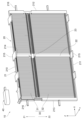
図2に示されるように、シャッタ装置10は、フレーム20と、複数のブレード30と、アクチュエータ装置40とを備えている。
Next, a specific structure of the
As shown in FIG. 2, the
フレーム20は、矩形枠状に形成された第1フレーム本体部21と、第1フレーム本体部21の枠内に十字状に配置される第2フレーム本体部22及び第3フレーム本体部23とを有している。
第1フレーム本体部21は、上側フレーム片210、下側フレーム片211、右側フレーム片212、及び左側フレーム片213を有している。第1フレーム本体部21の枠内の空間には、図1に示されるグリル開口部2から導入される空気が流れる。
The
The first frame
以下では、上側フレーム片210及び下側フレーム片211の長手方向をX軸方向とも称し、右側フレーム片212及び左側フレーム片213の長手方向をZ軸方向とも称する。また、Z軸方向の一方向であるZ1方向を「上方」と称し、Z軸方向の他方向であるZ2方向を「下方」と称する。さらに、X軸方向及びZ軸方向の両方に直交する方向をY軸方向とも称する。Y軸方向は、空気の流れ方向にも相当するため、以下では、Y軸方向を「空気流れ方向Y」とも称する。
Hereinafter, the longitudinal direction of the
第2フレーム本体部22は、第1フレーム本体部21を補強するために設けられている。第3フレーム本体部23は、ブレード30を保持し、且つ第1フレーム本体部21を補強するために設けられている。第2フレーム本体部22は、第1フレーム本体部21の上側フレーム片210と下側フレーム片211との間に設けられている。図2に示されるように、第3フレーム本体部23は、第1フレーム本体部21の右側フレーム片212と左側フレーム片213との間に設けられている。第2フレーム本体部22及び第3フレーム本体部23により、第1フレーム本体部21の枠内の空間が4つの領域に区画されている。
The second frame
複数のブレード30は、フレーム20の枠内の4つの領域にそれぞれ配置されている。フレーム20の枠内の4つの領域において、複数のブレード30は、Z軸方向に長手方向を有するように配置されるとともに、X軸方向に並べて配置されている。以下では、便宜上、複数のブレード30のうち、第1フレーム本体部21の上側フレーム片210と第3フレーム本体部23との間に配置されるブレード30を「上側ブレード31」と称し、下側フレーム片211と第3フレーム本体部23との間に配置されるブレード30を「下側ブレード32」と称する。
The plurality of
上側ブレード31の上端部は第1フレーム本体部21の上側フレーム片210により回転可能に支持され、上側ブレード31の下端部は第3フレーム本体部23により回転可能に支持されている。下側ブレード32の上端部は第3フレーム本体部23により回転可能に支持され、下側ブレード32の下端部は下側フレーム片211により回転可能に支持されている。
The upper end of the
図3に示されるように、第3フレーム本体部23には、リンク部材80が更に組み付けられている。リンク部材80は、X軸方向に延びるように形成されている。リンク部材80には、上側ブレード31の下端部及び下側ブレード32の上端部が連結されている。
第1フレーム本体部21の左側フレーム片213には、第3フレーム本体部23との連結部分から上方に延びるようにシャフト70が配置されている。シャフト70の上端部は、図2に示されるアクチュエータ装置40に連結される。なお、図2では、リンク部材80及びシャフト70の図示が省略されている。
As shown in FIG. 3, a
A
アクチュエータ装置40は、上側フレーム片210の一端部の上方にねじ等により固定される。アクチュエータ装置40は、電力の供給に基づいてシャフト70を回転させる。シャフト70の回転に基づいてリンク部材80が第3フレーム本体部23に対してX軸方向に相対変位することにより、リンク部材80から上側ブレード31及び下側ブレード32に回転力が付与される。これにより、上側ブレード31及び下側ブレード32が回転動作して、第1フレーム本体部21の枠内の空間が開閉される。具体的には、複数のブレード30が開状態であるとき、各ブレード30の間に隙間が形成されるため、その隙間を通じてグリル開口部2からエンジンルーム3に空気が流れ込むことが可能となる。複数のブレード30が閉状態であるとき、各ブレード30の間の隙間が閉塞されるため、グリル開口部2からエンジンルーム3への空気の流れが遮断される。このように、本実施形態では、複数のブレード30が、フレーム20の枠内の空間を開閉する開閉部に相当する。
The
図2に示されるように、第1フレーム本体部21の上側フレーム片210及び下側フレーム片211には、複数の第1突出部214及び複数の第2突出部215がそれぞれ形成されている。第1突出部214は、上側フレーム片210及び下側フレーム片211から空気流れ方向Yに突出するように形成されている。第2突出部215は、上側フレーム片210及び下側フレーム片211から空気流れ方向Yとは逆の方向に突出するように形成されている。第1突出部214及び第2突出部215は矩形状に形成されている。
As shown in FIG. 2, a plurality of
第1フレーム本体部21の右側フレーム片212及び左側フレーム片213には、第3突出部216がそれぞれ形成されている。第3突出部216は、右側フレーム片212及び左側フレーム片213からX軸方向と平行な方向に、換言すれば空気流れ方向Yと直交する方向に突出するように形成されている。第3突出部216も矩形状に形成されている。
A
フレーム20では、第1突出部214、第2突出部215、及び第3突出部216がラジエータ5及びコンデンサ6に接触することにより、フレーム本体部21~23の変形が抑制されている。
次に、フレーム20の変形抑制構造について詳しく説明する。はじめに、ラジエータ5及びコンデンサ6の構造について説明する。
In the
Next, the deformation suppressing structure of the
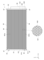
図4に示されるように、ラジエータ5は、熱交換コア部50と、第1タンク51と、第2タンク52と、第1サイドプレート53と、第2サイドプレート54とを備えている。ラジエータ5では、第1タンク51、第2タンク52、第1サイドプレート53、及び第2サイドプレート54が、熱交換コア部50を除く部分に相当する。
As shown in FIG. 4, the
熱交換コア部50は、複数のチューブ501と、複数のフィン502とにより構成されている。熱交換コア部50は、チューブ501の内部を流れる冷却水と、チューブ501の外部を流れる空気との間で熱交換を行う部分である。本実施形態では、冷却水及び空気が流体に相当する。
The heat
複数のチューブ501は、所定の間隔を空けてZ軸方向に積層して配置されている。したがって、本実施形態では、Z軸方向がチューブ積層方向に相当する。複数のチューブ501は、扁平状の管であり、X軸方向に延びるように形成されている。各チューブ501の内部空間は、冷却水が流れる流路を構成している。隣り合うチューブ501,501の間に形成される隙間には空気が流れる。
The plurality of
フィン502は、隣り合うチューブ501,501の間に形成される隙間に配置されている。フィン502は、薄い金属板を波状に折り曲げることにより形成される、いわゆるコルゲートフィンである。フィン502は、空気に対する伝熱面積を増加させることにより、ラジエータ5の熱交換性能を向上させる機能を有している。
The
第1タンク51は、各チューブ501の一端部に接続されるように設けられている。第1タンク51は、コアプレート510と、タンク部材511とにより構成されている。
図4及び図5に示されるように、コアプレート510は、Z軸方向に延びるように形成された平板状の部材からなる。タンク部材511は、Z軸方向に直交する断面形状がU字状をなすように形成された部材からなる。コアプレート510は、タンク部材511の開口部分を閉塞するようにタンク部材511に接合されている。タンク部材511の内壁面及びコアプレート510によって囲まれる空間により、第1タンク51の内部空間が形成されている。第1タンク51の内部空間は、冷却水の流れる内部流路を構成している。
The
As shown in FIGS. 4 and 5, the
図4に示されるように、コアプレート510には、各チューブ501の一端部が挿入される挿入孔510aが形成されている。挿入孔510aに挿入された各チューブ501の一端部は、第1タンク51の内部流路まで延びている。これにより、第1タンク51の内部流路と各チューブ501の内部流路とが連通されている。
As shown in FIG. 4, the
第2タンク52は、各チューブ501の他端部に接続されるように設けられている。第2タンク52も、第1タンク51と同様に、コアプレート520と、タンク部材521とにより構成されている。第2タンク52の構造は、第1タンク51の構造と略同一であるため、その詳細な説明を省略する。
The
第1サイドプレート53及び第2サイドプレート54は、熱交換コア部50の両端部にそれぞれ設けられている。サイドプレート53,54は、X軸方向に直交する断面形状がコ字状に形成された板状の部材からなる。サイドプレート53,54は、コ字の開口部分が熱交換コア部50の外側を向くように配置されている。サイドプレート53,54のそれぞれの一端部は第1タンク51に固定されており、サイドプレート53,54のそれぞれの他端部は第2タンク52に固定されている。サイドプレート53,54は、熱交換コア部50を補強するために設けられている。
The
ラジエータ5では、車両の内燃機関の熱を吸収することにより温度が上昇した冷却水が、第1タンク51に形成された流入口を通じて第1タンク51の内部流路に流入する。第1タンク51の内部流路に流入した冷却水は、熱交換コア部50の各チューブ501に分配される。熱交換コア部50では、各チューブ501の内部を流れる冷却水と、各チューブ501の外部を流れる空気との間で熱交換が行われることにより、冷却水が冷却される。各チューブ501を通過した冷却水は、第2タンク52において集められた後、第2タンク52に形成された流出口を通じて外部に排出される。
In the
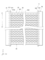
図6に示されるように、コンデンサ6は、ラジエータ5と略同一の構造を有しており、熱交換コア部60と、第1タンク61と、第2タンク62と、第1サイドプレート63と、第2サイドプレート64とを備えている。
熱交換コア部60は、複数のチューブ601と、複数のフィン602とにより構成されている。図7に示されるように、第1タンク61は、コアプレート610と、タンク部材611とにより構成されている。第2タンク62は、コアプレート620と、タンク部材621とにより構成されている。これらの構成要素の構造及び機能は、ラジエータ5において対応する各構成要素の構造及び機能と同一又は類似であるため、それらの相違点を中心に説明する。
As shown in FIG. 6, the
The heat
図6に示されるように、第1タンク61の内部には仕切板612が設けられている。仕切板612は、第1タンク61の内部空間を第1内部流路S11と第2内部流路S12とに区画している。第1タンク61には、第1内部流路S11に流体を流入させるための流入口65が設けられるとともに、第2内部流路S12から流体を流出させる流出口66が設けられている。第1タンク61の両端部には、第1タンク61の端部に形成される開口部分を閉塞するためのキャップ67がそれぞれ組み付けられている。
As shown in FIG. 6, a
第2タンク62の内部には仕切板622が設けられている。仕切板622は、第2タンク62の内部空間を第1内部流路S21と第2内部流路S22とに区画している。第2タンク62の第1内部流路S21は、複数のチューブ601のうち、上方に配置される複数のチューブ601aを介して第1タンク61の第1内部流路S11に連通されている。第2タンク62の第2内部流路S22は、複数のチューブ601のうち、下方に配置される複数のチューブ601bを介して第1タンク61の第2内部流路S12に連通されている。第2タンク62の両端部には、第2タンク62の端部に形成される開口部分を閉塞するためのキャップ67がそれぞれ組み付けられている。
コンデンサ6は、第2タンク62に隣接して配置される筒状の受液器68を更に備えている。受液器68の内部空間は、第2タンク62の第1内部空間S21及び第2内部空間S22に連通されている。
A
The
コンデンサ6では、車両の空調装置の冷凍サイクルを循環する冷媒が、第1タンク61に形成された流入口65を通じて第1タンク61の第1内部流路S11に流入する。第1タンク61の第1内部流路S11に流入した気相状の冷媒は熱交換コア部60の上方チューブ601aに分配される。熱交換コア部60では、上方チューブ601aの内部を流れる気相状の冷媒と、上方チューブ601aの外部を流れる空気との間で熱交換が行われることにより、気相状の冷媒が冷却されて液相状の冷媒に凝縮される。上方チューブ601aを通過した冷媒は、第2タンク62の第1内部流路S21において集められた後、受液器68に流入することにより、気相状の冷媒と液相状の冷媒とに分離される。受液器68において分離された液相状の冷媒は、第2タンク62の第2内部流路S22を通じて熱交換コア部60の下方チューブ601bに分配される。熱交換コア部60では、下方チューブ601bの内部を流れる液相状の冷媒と、下方チューブ601bの外部を流れる空気との間で熱交換が行われることにより、液相状の冷媒が過冷却される。下方チューブ601bを通過した冷媒は、第1タンク61の第2内部流路S12において集められた後、第1タンク61の流出口66を通じて外部に排出される。
In the
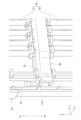
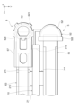
ラジエータ5及びコンデンサ6は、図5に示されるように配置されている。図5に示されるように、ラジエータ5及びコンデンサ6は、空気流れ方向Yに所定の隙間を有して配置されている。ラジエータ5とコンデンサ6との間に形成される隙間には、図2に示されるシャッタ装置10が配置されている。
The
図5に示されるように、第1フレーム本体部21の上側フレーム片210に形成される第1突出部214は、上側フレーム片210からラジエータ5の第1サイドプレート53に向かって突出しており、ラジエータ5の第1サイドプレート53に面接触している。また、上側フレーム片210に形成される第2突出部215は、上側フレーム片210からコンデンサ6の第1サイドプレート63に向かって突出しており、コンデンサ6の第1サイドプレート63に面接触している。より詳細には、第2突出部215は、コンデンサ6の第1サイドプレート63のうち、キャップ67により覆われてない部分に面接触している。このような構造により、上側フレーム片210は、第1突出部214及び第2突出部215を介してラジエータ5の第1サイドプレート53及びコンデンサ6の第1サイドプレート63により挟み込まれている。
As shown in FIG. 5, the
なお、図示は省略するが、第1フレーム本体部21の下側フレーム片211に形成される第1突出部214は、下側フレーム片211からラジエータ5の第2サイドプレート54に向かって突出しており、ラジエータ5の第2サイドプレート54に面接触している。また、下側フレーム片211に形成される第2突出部215は、下側フレーム片211からコンデンサ6の第2サイドプレート64に向かって突出しており、コンデンサ6の第2サイドプレート64に面接触している。下側フレーム片211は、第1突出部214及び第2突出部215を介してラジエータ5の第2サイドプレート54及びコンデンサ6の第2サイドプレート64により挟み込まれている。
Although not shown, the
図5に示されるように、第1フレーム本体部21の右側フレーム片212に形成される第3突出部216は、右側フレーム片212から、ラジエータ5の第2タンク52とコンデンサ6の第2タンク62との間に形成される隙間に向かって突出しており、それらにより挟み込まれている。より詳しくは、第3突出部216はラジエータ5の第2タンク52のコアプレート520とコンデンサ6の第2タンク62のタンク部材621とにより挟み込まれている。
As shown in FIG. 5, the
なお、図示は省略するが、第1フレーム本体部21の左側フレーム片213に形成される第3突出部216はラジエータ5の第1タンク51のコアプレート510とコンデンサ6の第1タンク61のタンク部材611とにより挟み込まれている。
以上説明した本実施形態のシャッタ装置10によれば、以下の(1)~(5)に示される作用及び効果を得ることができる。
Although not shown, the
According to the
(1)車両の振動等に伴ってフレーム本体部21~23が弾性変形した際に、各突出部214~216が、ラジエータ5の熱交換コア部50を除く部分、及びコンデンサ6の熱交換コア部60を除く部分に接触することにより、フレーム本体部21~23が変形し難くなる。また、フレーム本体部21~23の変形が抑制されることにより、フレーム本体部21~23に回転可能に支持されるブレード30も変形し難くなる。これにより、フレーム本体部21~23及びブレード30がラジエータ5の熱交換コア部50やコンデンサ6の熱交換コア部60に接触することを抑制できる。
(1) When the frame
(2)ブレード30が閉状態である場合には、グリル開口部2から導入される空気の風圧がブレード30に作用するため、空気流れ方向Yに向かってフレーム本体部21~23が弾性変形し易い。このようなフレーム本体部21~23の弾性変形によっても、ブレード30がラジエータ5の熱交換コア部60に接触する可能性がある。この点、本実施形態のシャッタ装置10では、第1突出部214が、第1フレーム本体部21の上側フレーム片210及び下側フレーム片211から空気流れ方向Yと平行な方向に突出するように、より詳しくは第1フレーム本体部21からラジエータ5のサイドプレート53,54に向かって突出するように形成されている。このような構成によれば、空気流れ方向Yに向かってフレーム本体部21~23が弾性変形するような場合、第1突出部214がラジエータ5のサイドプレート53,54に接触することにより、空気流れ方向Yに向かってフレーム本体部21~23が変形し難くなる。これにより、空気流れ方向Yに向かってブレード30も変形し難くなるため、フレーム本体部21~23及びブレード30がラジエータ5の熱交換コア部50に接触することを抑制できる。
(2) When the
(3)第1突出部214は、ラジエータ5の熱交換コア部50を除く部分に接触している。このような構成によれば、第1突出部214とラジエータ5との間に隙間が形成されている場合と比較すると、ラジエータ5に向かう方向へのフレーム本体部21~23の変形を、より効果的に抑制することができるため、フレーム本体部21~23やブレード30がラジエータ5の熱交換コア部50に更に接触し難くなる。また、第2突出部215は、コンデンサ6の熱交換コア部60を除く部分に接触しているため、フレーム本体部21~23やブレード30がコンデンサ6の熱交換コア部60に更に接触し難くなる。
(3) The first protruding
(4)第1突出部214及び第2突出部215は、空気流れ方向Yに並ぶように配置されている。このような構成によれば、例えば図8に示されるように第1突出部214と第2突出部215とが、X軸方向にずれるように配置されている構造と比較すると、より的確に第1フレーム本体部21の変形を抑制できるため、フレーム本体部21~23及びブレード30がラジエータ5の熱交換コア部50やコンデンサ6の熱交換コア部60に更に接触し難くなる。なお、本実施形態のシャッタ装置10では、図8に示されるような構造を採用することも可能である。
(4) The
(5)第3突出部216は、第1フレーム本体部21の右側フレーム片212及び左側フレーム片213から空気流れ方向Yと直交する方向に突出するように形成されている。左側フレーム片213に形成される第3突出部216は、ラジエータ5の第1タンク51のコアプレート510とコンデンサ6の第1タンク61のタンク部材611とにより挟み込まれている。右側フレーム片212に形成される第3突出部216は、ラジエータ5の第2タンク52のコアプレート520とコンデンサ6の第2タンク62のタンク部材621とにより挟み込まれている。すなわち、第3突出部216は、ラジエータ5及びコンデンサ6のそれぞれの熱交換コア部50,60を除く部分に挟み込まれている。このような構成によれば、第1フレーム本体部21の右側フレーム片212及び左側フレーム片213の変形を抑制できるため、フレーム本体部21~23及びブレード30がラジエータ5の熱交換コア部50やコンデンサ6の熱交換コア部60に更に接触し難くなる。
(5) The
<第2実施形態>
次に、第2実施形態のシャッタ装置10について説明する。以下、第1実施形態のシャッタ装置10との相違点を中心に説明する。
図9に示されるように、本実施形態のシャッタ装置10では、第3突出部216が第1部位216aと第2部位216bとを有している。
<Second embodiment>
Next, a
As shown in FIG. 9, in the
第1部位216aは、第1フレーム本体部21の右側フレーム片212からX軸方向に平行な方向に延びるように形成されている。第1部位216aにおいて空気流れ方向Yとは逆方向に位置する外面は、コンデンサ6の第2タンク62のタンク部材621に面接触している。
The first portion 216a is formed to extend from the
第2部位216bは、第1部位216aの先端部から空気流れ方向Yに向かって略直角に折り曲げられるように形成されている。第2部位216bの先端部は、ラジエータ5の第2タンク52のタンク部材521の外面に面接触している。
このように、第3突出部216は、その第1部位216aがコンデンサ6の第2タンク62のタンク部材621に面接触し、且つその第2部位216bがラジエータ5の第2タンク52のタンク部材521に面接触することにより、コンデンサ6及びラジエータ5により挟み込まれている。
The second portion 216b is formed to be bent at a substantially right angle toward the air flow direction Y from the tip of the first portion 216a. The tip of the second portion 216b is in surface contact with the outer surface of the
In this way, the
なお、第1フレーム本体部21の左側フレーム片213にも、同一の形状からなる第3突出部216が形成されている。この右側フレーム片212に形成されている第3突出部216は、その第1部位216aがコンデンサ6の第1タンク61のタンク部材611に面接触し、且つその第2部位216bがラジエータ5の第1タンク51のタンク部材511に面接触することにより、コンデンサ6及びラジエータ5により挟み込まれている。
Note that a
以上説明した本実施形態のシャッタ装置10によれば、上記の(1)~(4)に示される作用及び効果に加え、以下の(6)に示される作用及び効果を得ることができる。
(6)右側フレーム片212に形成される第3突出部216は、ラジエータ5の第2タンク52のタンク部材521とコンデンサ6の第2タンク62のタンク部材621とにより挟み込まれている。左側フレーム片213に形成される第3突出部216は、ラジエータ5の第1タンク51のタンク部材511とコンデンサ6の第1タンク61のタンク部材611とにより挟み込まれている。このような構成であっても、第1フレーム本体部21の右側フレーム片212及び左側フレーム片213の変形を抑制できるため、フレーム本体部21~23及びブレード30がラジエータ5の熱交換コア部50やコンデンサ6の熱交換コア部60に更に接触し難くなる。
According to the
(6) The
<他の実施形態>
なお、上記実施形態は、以下の形態にて実施することもできる。
・各実施形態のシャッタ装置10は、ラジエータ5とコンデンサ6との間に配置されるものに限らず、任意の2つの熱交換器の間に配置されるものであればよい。例えば車両の内燃機関の吸気を冷却する吸気冷却器とコンデンサとが空気流れ方向Yに並べて配置されている場合には、それらの間にシャッタ装置を配置してもよい。
<Other embodiments>
Note that the above embodiment can also be implemented in the following forms.
- The
・各実施形態のシャッタ装置10には、第1突出部214、第2突出部215、及び第3突出部216のうちの少なくとも一つが設けられていればよい。
・第1突出部214とラジエータ5のサイドプレート53,54との間には隙間が形成されていてもよい。同様に、第2突出部215とコンデンサ6のサイドプレート63,64との間にも隙間が形成されていてもよい。更に、第3突出部216とラジエータ5のタンク51,52との間、並びに第3突出部216とコンデンサ6のタンク61,62との間にも隙間が形成されていてもよい。
- The
- A gap may be formed between the
・各実施形態のシャッタ装置10は、フレーム20の枠内の空間を開閉する開閉部として複数のブレード30を用いるものであったが、開閉部としてスクリーン等を用いるものであってもよい。
・本開示は上記の具体例に限定されるものではない。上記の具体例に、当業者が適宜設計変更を加えたものも、本開示の特徴を備えている限り、本開示の範囲に包含される。前述した各具体例が備える各要素、及びその配置、条件、形状等は、例示したものに限定されるわけではなく適宜変更することができる。前述した各具体例が備える各要素は、技術的な矛盾が生じない限り、適宜組み合わせを変えることができる。
- Although the
- The present disclosure is not limited to the above specific examples. Design changes made by those skilled in the art to the specific examples described above are also included within the scope of the present disclosure as long as they have the characteristics of the present disclosure. The elements included in each of the specific examples described above, as well as their arrangement, conditions, shapes, etc., are not limited to those illustrated, and can be changed as appropriate. The elements included in each of the specific examples described above can be appropriately combined as long as no technical contradiction occurs.
C:車両
2:グリル開口部
5:ラジエータ(第2熱交換器)
6:コンデンサ(第1熱交換器)
10:シャッタ装置
20:フレーム
21:フレーム本体部
30:ブレード(開閉部)
50,60:熱交換コア部
53,54,63,64:サイドプレート
214:第1突出部
215:第2突出部
216:第3突出部
501,601:チューブ
510,520,610,620:コアプレート
511,521,611,621:タンク部材
C: Vehicle 2: Grill opening 5: Radiator (second heat exchanger)
6: Condenser (first heat exchanger)
10: Shutter device 20: Frame 21: Frame main body part 30: Blade (opening/closing part)
50, 60: Heat
Claims (7)
前記フレームの枠内の空間を開閉する開閉部(30)と、を備え、
前記熱交換器において、内部を流れる流体と外部を流れる流体との間で熱交換が行われる部分を熱交換コア部(50,60)とし、
前記2つの熱交換器のうち、より空気流れ方向の上流に配置される熱交換器を第1熱交換器(6)とし、前記第1熱交換器に対して空気流れ方向の下流に配置される熱交換器を第2熱交換器(5)とするとき、
前記フレームは、
枠を形成するフレーム本体部(21)と、
前記フレーム本体部から前記第2熱交換器の前記熱交換コア部を除く部分に向かって突出するように形成される第1突出部(214)と、
前記フレーム本体部から前記第1熱交換器の前記熱交換コア部を除く部分に向かって突出するように形成される第2突出部(215)と、を有しており、
前記第1突出部及び前記第2突出部は、前記フレーム本体部から空気流れ方向と平行な方向に突出するように形成されており、
前記熱交換コア部は、複数のチューブ(501,601)が積層された構造からなるものであり、
複数の前記チューブが積層して配置される方向をチューブ積層方向とするとき、
前記第1熱交換器及び前記第2熱交換器は、前記チューブ積層方向における前記熱交換コア部の端部に配置され、且つ前記熱交換コア部を補強するサイドプレート(53,54,63,64)をそれぞれ有するものであり、
前記第1熱交換器における前記熱交換コア部を除く部分は、前記第1熱交換器の前記サイドプレート(53,54)であり、
前記第2熱交換器における前記熱交換コア部を除く部分は、前記第2熱交換器の前記サイドプレート(63,64)であり、
前記第1突出部は、前記第2熱交換器の前記サイドプレートに接触しており、
前記第2突出部は、前記第1熱交換器の前記サイドプレートに接触している
車両のシャッタ装置。 A frame ( 20 )and,
An opening/closing part (30) that opens and closes a space within the frame,
In the heat exchanger, a portion where heat exchange is performed between the fluid flowing inside and the fluid flowing outside is referred to as a heat exchange core portion (50, 60),
Of the two heat exchangers, the heat exchanger disposed more upstream in the air flow direction is a first heat exchanger (6), and the heat exchanger (6) is disposed downstream in the air flow direction with respect to the first heat exchanger (6). When the heat exchanger is the second heat exchanger (5),
The frame is
a frame main body (21) forming a frame;
a first protrusion (214) formed to protrude from the frame main body toward a portion of the second heat exchanger excluding the heat exchange core;
a second protruding portion (215) formed to protrude from the frame main body toward a portion of the first heat exchanger excluding the heat exchange core portion;
The first protrusion and the second protrusion are formed to protrude from the frame main body in a direction parallel to the air flow direction,
The heat exchange core section has a structure in which a plurality of tubes (501, 601) are stacked,
When the direction in which the plurality of tubes are stacked and arranged is the tube stacking direction,
The first heat exchanger and the second heat exchanger include side plates (53, 54, 63, 64), respectively.
A portion of the first heat exchanger other than the heat exchange core portion is the side plate (53, 54) of the first heat exchanger,
A portion of the second heat exchanger other than the heat exchange core portion is the side plate (63, 64) of the second heat exchanger,
The first protrusion is in contact with the side plate of the second heat exchanger,
The second protrusion is in contact with the side plate of the first heat exchanger.
Vehicle shutter device.
請求項1に記載の車両のシャッタ装置。 The shutter device for a vehicle according to claim 1 , wherein the first protrusion and the second protrusion are arranged side by side in the air flow direction.
請求項1に記載の車両のシャッタ装置。 The vehicle shutter device according to claim 1 , wherein the first protrusion and the second protrusion are arranged to be offset in a direction perpendicular to an air flow direction.
前記フレームの枠内の空間を開閉する開閉部(30)と、を備え、
前記熱交換器において、内部を流れる流体と外部を流れる流体との間で熱交換が行われる部分を熱交換コア部(50,60)とするとき、
前記フレームは、
枠を形成するフレーム本体部(21)と、
前記フレーム本体部から、2つの前記熱交換器の少なくとも一方の熱交換器の前記熱交換コア部を除く部分に向かって突出するように形成される突出部(216)と、を有しており、
前記突出部は、前記フレーム本体部から空気流れ方向と直交する方向に突出するように形成されとともに、2つの前記熱交換器のそれぞれの前記熱交換コア部を除く部分に挟み込まれており、
前記熱交換コア部は、複数のチューブ(501,601)が積層された構造からなるものであり、
複数の前記チューブが積層して配置される方向をチューブ積層方向とするとき、
前記熱交換器は、
複数の前記チューブのそれぞれの端部が接続されるコアプレート(510,520,610,620)と、
前記コアプレートと共に流体の流れる流路を形成するタンク部材(511,521,611,621)と、を有し、
2つの前記熱交換器のうち、一方の前記熱交換器(5)における前記熱交換コア部を除く部分は、前記コアプレート(510,520)であり、他方の前記熱交換器(6)における前記熱交換コア部を除く部分は、前記タンク部材(611,621)であり、
前記突出部は、一方の前記熱交換器の前記コアプレートと、他方の前記熱交換器の前記タンク部材との間に挟み込まれている
車両のシャッタ装置。 A frame ( 20 )and,
An opening/closing part (30) that opens and closes a space within the frame,
In the heat exchanger, when the portion where heat exchange is performed between the fluid flowing inside and the fluid flowing outside is a heat exchange core portion (50, 60),
The frame is
a frame main body (21) forming a frame;
a protrusion (216) formed to protrude from the frame main body toward a portion of at least one of the two heat exchangers excluding the heat exchange core portion; ,
The protruding portion is formed to protrude from the frame main body in a direction perpendicular to the air flow direction, and is sandwiched between the two heat exchangers except for the heat exchange core portion,
The heat exchange core section has a structure in which a plurality of tubes (501, 601) are stacked,
When the direction in which the plurality of tubes are stacked and arranged is the tube stacking direction,
The heat exchanger is
a core plate (510, 520, 610, 620) to which each end of the plurality of tubes is connected;
A tank member (511, 521, 611, 621) forming a flow path through which fluid flows together with the core plate,
Of the two heat exchangers, the core plate (510, 520) is the core plate (510, 520) in one of the heat exchangers (5), and the part in the other heat exchanger (6) is the core plate (510, 520). The portion excluding the heat exchange core portion is the tank member (611, 621),
The projecting portion is sandwiched between the core plate of one of the heat exchangers and the tank member of the other heat exchanger. The vehicle shutter device.
前記フレームの枠内の空間を開閉する開閉部(30)と、を備え、
前記熱交換器において、内部を流れる流体と外部を流れる流体との間で熱交換が行われる部分を熱交換コア部(50,60)とするとき、
前記フレームは、
枠を形成するフレーム本体部(21)と、
前記フレーム本体部から、2つの前記熱交換器の少なくとも一方の熱交換器の前記熱交換コア部を除く部分に向かって突出するように形成される突出部(216)と、を有しており、
前記突出部は、前記フレーム本体部から空気流れ方向と直交する方向に突出するように形成されとともに、2つの前記熱交換器のそれぞれの前記熱交換コア部を除く部分に挟み込まれており、
前記熱交換コア部は、複数のチューブ(501,601)が積層された構造からなるものであり、
複数の前記チューブが積層して配置される方向をチューブ積層方向とするとき、
前記熱交換器は、
複数の前記チューブのそれぞれの端部が接続されるコアプレート(510,520,610,620)と、
前記コアプレートと共に流体の流れる流路を形成するタンク部材(511,521,611,621)と、を有し、
2つの前記熱交換器の前記熱交換コア部を除く部分は、前記タンク部材(511,521,611,621)であり、
前記突出部は、2つの前記熱交換器のそれぞれの前記タンク部材の間に挟み込まれている
車両のシャッタ装置。 A frame ( 20 )and,
An opening/closing part (30) that opens and closes a space within the frame,
In the heat exchanger, when the portion where heat exchange is performed between the fluid flowing inside and the fluid flowing outside is a heat exchange core portion (50, 60),
The frame is
a frame main body (21) forming a frame;
a protrusion (216) formed to protrude from the frame main body toward a portion of at least one of the two heat exchangers excluding the heat exchange core portion; ,
The protruding portion is formed to protrude from the frame main body in a direction perpendicular to the air flow direction, and is sandwiched between the two heat exchangers except for the heat exchange core portion,
The heat exchange core section has a structure in which a plurality of tubes (501, 601) are stacked,
When the direction in which the plurality of tubes are stacked and arranged is the tube stacking direction,
The heat exchanger is
a core plate (510, 520, 610, 620) to which each end of the plurality of tubes is connected;
A tank member (511, 521, 611, 621) forming a flow path through which fluid flows together with the core plate,
A portion of the two heat exchangers excluding the heat exchange core portion is the tank member (511, 521, 611, 621),
The projecting portion is sandwiched between the tank members of each of the two heat exchangers. The vehicle shutter device.
請求項1~5のいずれか一項に記載の車両のシャッタ装置。 The heat exchanger includes a radiator (5) that cools the cooling water circulating in the vehicle, a condenser (6) of a refrigeration cycle mounted on the vehicle, and an intake air cooler that cools the intake air of the internal combustion engine of the vehicle. The vehicle shutter device according to any one of claims 1 to 5 .
請求項1~6のいずれか一項に記載の車両のシャッタ装置。
The vehicle according to any one of claims 1 to 6 , wherein the opening/closing part is a plurality of blades (30) that are rotatably supported by the frame and open and close a space within the frame by rotational movement. shutter device.
Priority Applications (4)
| Application Number | Priority Date | Filing Date | Title |
|---|---|---|---|
| JP2019137737A JP7388030B2 (en) | 2019-07-26 | 2019-07-26 | vehicle shutter device |
| CN202080054359.0A CN114174095B (en) | 2019-07-26 | 2020-07-14 | Air door device of vehicle |
| PCT/JP2020/027365 WO2021020108A1 (en) | 2019-07-26 | 2020-07-14 | Shutter device for vehicle |
| US17/582,199 US20220144077A1 (en) | 2019-07-26 | 2022-01-24 | Shutter device for vehicle |
Applications Claiming Priority (1)
| Application Number | Priority Date | Filing Date | Title |
|---|---|---|---|
| JP2019137737A JP7388030B2 (en) | 2019-07-26 | 2019-07-26 | vehicle shutter device |
Publications (3)
| Publication Number | Publication Date |
|---|---|
| JP2021020537A JP2021020537A (en) | 2021-02-18 |
| JP2021020537A5 JP2021020537A5 (en) | 2021-11-11 |
| JP7388030B2 true JP7388030B2 (en) | 2023-11-29 |
Family
ID=74230267
Family Applications (1)
| Application Number | Title | Priority Date | Filing Date |
|---|---|---|---|
| JP2019137737A Active JP7388030B2 (en) | 2019-07-26 | 2019-07-26 | vehicle shutter device |
Country Status (4)
| Country | Link |
|---|---|
| US (1) | US20220144077A1 (en) |
| JP (1) | JP7388030B2 (en) |
| CN (1) | CN114174095B (en) |
| WO (1) | WO2021020108A1 (en) |
Citations (6)
| Publication number | Priority date | Publication date | Assignee | Title |
|---|---|---|---|---|
| JP2003034130A (en) | 2001-07-24 | 2003-02-04 | Hitachi Ltd | Air conditioner for automobile |
| JP2012001184A (en) | 2010-06-21 | 2012-01-05 | Toyota Motor Corp | Radiator shutter |
| JP2012224153A (en) | 2011-04-18 | 2012-11-15 | Toyota Motor Corp | Shutter device for vehicle |
| JP2013505873A (en) | 2009-09-29 | 2013-02-21 | ヴァレオ システム テルミク | Heat exchange block for automobile |
| JP2018192882A (en) | 2017-05-16 | 2018-12-06 | 株式会社デンソー | Shutter structure for vehicular heat exchanger |
| JP2019100389A (en) | 2017-11-29 | 2019-06-24 | 株式会社デンソー | Connecting member and structure module |
Family Cites Families (8)
| Publication number | Priority date | Publication date | Assignee | Title |
|---|---|---|---|---|
| CN1441220A (en) * | 2002-02-28 | 2003-09-10 | 文特-阿克西亚有限公司 | Heat exchange device |
| JP2004249946A (en) * | 2003-02-21 | 2004-09-09 | Japan Climate Systems Corp | Vehicular air conditioner |
| DE102004058724B4 (en) * | 2003-12-09 | 2018-11-15 | Denso Corporation | Heat exchanger and cooling module with this |
| JP2011201439A (en) * | 2010-03-25 | 2011-10-13 | Aisin Seiki Co Ltd | Movable grille shutter for vehicle |
| DE102011004988B4 (en) * | 2011-03-02 | 2023-02-09 | Ford Global Technologies, Llc | Air guide nozzle for ventilation of the interior of a motor vehicle |
| JP2018079757A (en) * | 2016-11-15 | 2018-05-24 | 株式会社デンソー | Air stream circulation structure of vehicle |
| JP6604318B2 (en) * | 2016-11-30 | 2019-11-13 | 豊田合成株式会社 | Air conditioning register |
| CN109489472A (en) * | 2018-11-21 | 2019-03-19 | 珠海格力电器股份有限公司 | Heat exchanger assembly, heat exchanger and air-conditioning device |
-
2019
- 2019-07-26 JP JP2019137737A patent/JP7388030B2/en active Active
-
2020
- 2020-07-14 WO PCT/JP2020/027365 patent/WO2021020108A1/en active Application Filing
- 2020-07-14 CN CN202080054359.0A patent/CN114174095B/en active Active
-
2022
- 2022-01-24 US US17/582,199 patent/US20220144077A1/en active Pending
Patent Citations (6)
| Publication number | Priority date | Publication date | Assignee | Title |
|---|---|---|---|---|
| JP2003034130A (en) | 2001-07-24 | 2003-02-04 | Hitachi Ltd | Air conditioner for automobile |
| JP2013505873A (en) | 2009-09-29 | 2013-02-21 | ヴァレオ システム テルミク | Heat exchange block for automobile |
| JP2012001184A (en) | 2010-06-21 | 2012-01-05 | Toyota Motor Corp | Radiator shutter |
| JP2012224153A (en) | 2011-04-18 | 2012-11-15 | Toyota Motor Corp | Shutter device for vehicle |
| JP2018192882A (en) | 2017-05-16 | 2018-12-06 | 株式会社デンソー | Shutter structure for vehicular heat exchanger |
| JP2019100389A (en) | 2017-11-29 | 2019-06-24 | 株式会社デンソー | Connecting member and structure module |
Also Published As
| Publication number | Publication date |
|---|---|
| CN114174095B (en) | 2024-02-09 |
| JP2021020537A (en) | 2021-02-18 |
| WO2021020108A1 (en) | 2021-02-04 |
| CN114174095A (en) | 2022-03-11 |
| US20220144077A1 (en) | 2022-05-12 |
Similar Documents
| Publication | Publication Date | Title |
|---|---|---|
| JP6520681B2 (en) | Heat exchanger | |
| JP2008180486A (en) | Heat exchanger | |
| WO2007088850A1 (en) | Heat exchanger for vehicle | |
| WO2014097977A1 (en) | Combined heat exchanger | |
| CN113383205B (en) | Heat exchanger | |
| JP7388030B2 (en) | vehicle shutter device | |
| JP4276893B2 (en) | Vehicle heat exchange device | |
| WO2020184315A1 (en) | Heat exchanger | |
| JP5772608B2 (en) | Heat exchanger | |
| JP7439537B2 (en) | Heat exchanger | |
| KR100759792B1 (en) | Integral heat exchanger | |
| KR101855850B1 (en) | Integrated heat exchanger | |
| JP4397676B2 (en) | Automotive heat exchanger | |
| US20240102745A1 (en) | Heat exchanger | |
| JP3861787B2 (en) | Composite heat exchanger and automobile equipped with the same | |
| KR102533346B1 (en) | Integrated heat exchanger | |
| WO2021210428A1 (en) | Heat exchanger | |
| KR101422712B1 (en) | Integrated Heat Exchanger | |
| WO2021019953A1 (en) | Heat exchange unit | |
| JP6605338B2 (en) | Evaporator with cool storage function | |
| JP6197746B2 (en) | Heat exchanger | |
| JP2021020537A5 (en) | ||
| JP2005083653A (en) | Refrigerant evaporator | |
| KR20230115727A (en) | Heat exchanger | |
| KR20230136254A (en) | Cooling module |
Legal Events
| Date | Code | Title | Description |
|---|---|---|---|
| A521 | Request for written amendment filed |
Free format text: JAPANESE INTERMEDIATE CODE: A523 Effective date: 20211001 |
|
| A621 | Written request for application examination |
Free format text: JAPANESE INTERMEDIATE CODE: A621 Effective date: 20220601 |
|
| A131 | Notification of reasons for refusal |
Free format text: JAPANESE INTERMEDIATE CODE: A131 Effective date: 20230801 |
|
| A521 | Request for written amendment filed |
Free format text: JAPANESE INTERMEDIATE CODE: A523 Effective date: 20230927 |
|
| TRDD | Decision of grant or rejection written | ||
| A01 | Written decision to grant a patent or to grant a registration (utility model) |
Free format text: JAPANESE INTERMEDIATE CODE: A01 Effective date: 20231017 |
|
| A61 | First payment of annual fees (during grant procedure) |
Free format text: JAPANESE INTERMEDIATE CODE: A61 Effective date: 20231030 |
|
| R151 | Written notification of patent or utility model registration |
Ref document number: 7388030 Country of ref document: JP Free format text: JAPANESE INTERMEDIATE CODE: R151 |