JP7387491B2 - gaming machine - Google Patents
gaming machine Download PDFInfo
- Publication number
- JP7387491B2 JP7387491B2 JP2020035690A JP2020035690A JP7387491B2 JP 7387491 B2 JP7387491 B2 JP 7387491B2 JP 2020035690 A JP2020035690 A JP 2020035690A JP 2020035690 A JP2020035690 A JP 2020035690A JP 7387491 B2 JP7387491 B2 JP 7387491B2
- Authority
- JP
- Japan
- Prior art keywords
- performance
- display
- period
- game
- jackpot
- Prior art date
- Legal status (The legal status is an assumption and is not a legal conclusion. Google has not performed a legal analysis and makes no representation as to the accuracy of the status listed.)
- Active
Links
- 230000000694 effects Effects 0.000 claims description 1419
- 238000004519 manufacturing process Methods 0.000 claims description 353
- 230000008859 change Effects 0.000 claims description 131
- 230000002250 progressing effect Effects 0.000 claims description 25
- 238000000034 method Methods 0.000 description 584
- 230000008569 process Effects 0.000 description 577
- 230000015654 memory Effects 0.000 description 227
- 238000010586 diagram Methods 0.000 description 189
- 238000012545 processing Methods 0.000 description 171
- 238000003860 storage Methods 0.000 description 162
- 230000033001 locomotion Effects 0.000 description 127
- 239000000872 buffer Substances 0.000 description 116
- 238000012790 confirmation Methods 0.000 description 66
- 238000001514 detection method Methods 0.000 description 59
- 230000008901 benefit Effects 0.000 description 53
- 230000004397 blinking Effects 0.000 description 49
- 238000013024 troubleshooting Methods 0.000 description 45
- 230000007423 decrease Effects 0.000 description 42
- 230000001965 increasing effect Effects 0.000 description 33
- 238000012986 modification Methods 0.000 description 31
- 230000004048 modification Effects 0.000 description 31
- 239000003086 colorant Substances 0.000 description 29
- 230000006870 function Effects 0.000 description 28
- 238000011084 recovery Methods 0.000 description 27
- 230000004044 response Effects 0.000 description 26
- 239000012536 storage buffer Substances 0.000 description 26
- 230000015572 biosynthetic process Effects 0.000 description 20
- 238000003786 synthesis reaction Methods 0.000 description 20
- 241000282472 Canis lupus familiaris Species 0.000 description 19
- 238000013461 design Methods 0.000 description 19
- OMFRMAHOUUJSGP-IRHGGOMRSA-N bifenthrin Chemical compound C1=CC=C(C=2C=CC=CC=2)C(C)=C1COC(=O)[C@@H]1[C@H](\C=C(/Cl)C(F)(F)F)C1(C)C OMFRMAHOUUJSGP-IRHGGOMRSA-N 0.000 description 15
- 238000007781 pre-processing Methods 0.000 description 15
- 230000002829 reductive effect Effects 0.000 description 15
- 239000011521 glass Substances 0.000 description 14
- 230000005540 biological transmission Effects 0.000 description 12
- 230000000052 comparative effect Effects 0.000 description 11
- 230000003031 feeding effect Effects 0.000 description 11
- 238000010304 firing Methods 0.000 description 11
- 238000003825 pressing Methods 0.000 description 10
- 239000004576 sand Substances 0.000 description 9
- 230000007704 transition Effects 0.000 description 9
- 238000011161 development Methods 0.000 description 8
- 230000018109 developmental process Effects 0.000 description 8
- 239000000779 smoke Substances 0.000 description 8
- 230000009471 action Effects 0.000 description 7
- 230000035553 feeding performance Effects 0.000 description 7
- 230000001795 light effect Effects 0.000 description 7
- 238000007726 management method Methods 0.000 description 7
- 238000012805 post-processing Methods 0.000 description 7
- 230000005856 abnormality Effects 0.000 description 6
- 238000004458 analytical method Methods 0.000 description 6
- 238000005520 cutting process Methods 0.000 description 6
- 230000009467 reduction Effects 0.000 description 6
- 230000000717 retained effect Effects 0.000 description 6
- 230000003247 decreasing effect Effects 0.000 description 5
- 238000009795 derivation Methods 0.000 description 5
- 239000000284 extract Substances 0.000 description 5
- 230000001788 irregular Effects 0.000 description 5
- 238000013459 approach Methods 0.000 description 4
- 238000004891 communication Methods 0.000 description 4
- 238000004590 computer program Methods 0.000 description 4
- 230000000994 depressogenic effect Effects 0.000 description 4
- 230000029087 digestion Effects 0.000 description 4
- 238000005401 electroluminescence Methods 0.000 description 4
- 230000014509 gene expression Effects 0.000 description 4
- 230000036961 partial effect Effects 0.000 description 4
- 239000000725 suspension Substances 0.000 description 4
- 206010037660 Pyrexia Diseases 0.000 description 3
- 241000722921 Tulipa gesneriana Species 0.000 description 3
- 230000003321 amplification Effects 0.000 description 3
- 230000002844 continuous effect Effects 0.000 description 3
- 238000013500 data storage Methods 0.000 description 3
- 238000003745 diagnosis Methods 0.000 description 3
- 230000002708 enhancing effect Effects 0.000 description 3
- 230000010354 integration Effects 0.000 description 3
- 238000007562 laser obscuration time method Methods 0.000 description 3
- 238000003199 nucleic acid amplification method Methods 0.000 description 3
- 238000004904 shortening Methods 0.000 description 3
- 238000002834 transmittance Methods 0.000 description 3
- KRQUFUKTQHISJB-YYADALCUSA-N 2-[(E)-N-[2-(4-chlorophenoxy)propoxy]-C-propylcarbonimidoyl]-3-hydroxy-5-(thian-3-yl)cyclohex-2-en-1-one Chemical compound CCC\C(=N/OCC(C)OC1=CC=C(Cl)C=C1)C1=C(O)CC(CC1=O)C1CCCSC1 KRQUFUKTQHISJB-YYADALCUSA-N 0.000 description 2
- 208000001613 Gambling Diseases 0.000 description 2
- 206010047571 Visual impairment Diseases 0.000 description 2
- 239000004020 conductor Substances 0.000 description 2
- 238000005034 decoration Methods 0.000 description 2
- 238000012938 design process Methods 0.000 description 2
- 230000008034 disappearance Effects 0.000 description 2
- 238000005286 illumination Methods 0.000 description 2
- 230000006872 improvement Effects 0.000 description 2
- 239000004973 liquid crystal related substance Substances 0.000 description 2
- 238000012544 monitoring process Methods 0.000 description 2
- 239000000758 substrate Substances 0.000 description 2
- 230000002459 sustained effect Effects 0.000 description 2
- 229920003002 synthetic resin Polymers 0.000 description 2
- 239000000057 synthetic resin Substances 0.000 description 2
- 230000000007 visual effect Effects 0.000 description 2
- 241000251468 Actinopterygii Species 0.000 description 1
- 241001465754 Metazoa Species 0.000 description 1
- 206010034719 Personality change Diseases 0.000 description 1
- 238000007792 addition Methods 0.000 description 1
- 230000003111 delayed effect Effects 0.000 description 1
- 210000005069 ears Anatomy 0.000 description 1
- 230000002996 emotional effect Effects 0.000 description 1
- 238000004880 explosion Methods 0.000 description 1
- 230000002349 favourable effect Effects 0.000 description 1
- PCHJSUWPFVWCPO-UHFFFAOYSA-N gold Chemical group [Au] PCHJSUWPFVWCPO-UHFFFAOYSA-N 0.000 description 1
- 239000010931 gold Substances 0.000 description 1
- 229910052737 gold Inorganic materials 0.000 description 1
- 230000012447 hatching Effects 0.000 description 1
- 238000010348 incorporation Methods 0.000 description 1
- 238000009434 installation Methods 0.000 description 1
- 230000002452 interceptive effect Effects 0.000 description 1
- 230000014759 maintenance of location Effects 0.000 description 1
- 230000007257 malfunction Effects 0.000 description 1
- 238000002156 mixing Methods 0.000 description 1
- 239000000203 mixture Substances 0.000 description 1
- 230000001151 other effect Effects 0.000 description 1
- 239000002243 precursor Substances 0.000 description 1
- 230000001737 promoting effect Effects 0.000 description 1
- 230000001360 synchronised effect Effects 0.000 description 1
- 238000012546 transfer Methods 0.000 description 1
- 239000012780 transparent material Substances 0.000 description 1
Images


Classifications
-
- Y—GENERAL TAGGING OF NEW TECHNOLOGICAL DEVELOPMENTS; GENERAL TAGGING OF CROSS-SECTIONAL TECHNOLOGIES SPANNING OVER SEVERAL SECTIONS OF THE IPC; TECHNICAL SUBJECTS COVERED BY FORMER USPC CROSS-REFERENCE ART COLLECTIONS [XRACs] AND DIGESTS
- Y02—TECHNOLOGIES OR APPLICATIONS FOR MITIGATION OR ADAPTATION AGAINST CLIMATE CHANGE
- Y02E—REDUCTION OF GREENHOUSE GAS [GHG] EMISSIONS, RELATED TO ENERGY GENERATION, TRANSMISSION OR DISTRIBUTION
- Y02E60/00—Enabling technologies; Technologies with a potential or indirect contribution to GHG emissions mitigation
- Y02E60/10—Energy storage using batteries
Landscapes
- Pinball Game Machines (AREA)
- Display Devices Of Pinball Game Machines (AREA)
Description
本発明は、遊技が可能な遊技機に関する。 The present invention relates to a gaming machine capable of playing games.
従来の遊技機は、リーチ演出としてバトル演出とタイマー演出とを同時期に実行可能であり、バトル演出中は、該バトル演出の再生速度を低速にするスローモーション演出を更に実行可能となっているものがある(例えば、特許文献1参照)。 Conventional gaming machines can execute a battle effect and a timer effect at the same time as a reach effect, and during a battle effect, it is also possible to execute a slow motion effect that slows down the playback speed of the battle effect. There are some (for example, see Patent Document 1).
しかしながら、特許文献1にあっては、スローモーション演出において改善の余地があった。
However, in
本発明は、このような問題点に着目してなされたもので、有利状態に制御されることを遊技者に印象付けることができる遊技機を提供することを目的とする。 The present invention has been made with attention to such problems, and an object of the present invention is to provide a gaming machine that can impress upon a player that the machine is controlled in an advantageous state .
手段Aの遊技機は、
可変表示の表示結果が特定表示結果となったときに遊技者にとって有利な有利状態に制御可能な遊技機であって、
音出力手段と、
表示手段と、
発光手段と、
演出を実行可能な演出実行手段と、
を備え、
前記演出実行手段は、前記有利状態に制御されることを示唆する特定演出を実行可能であり、
前記表示手段は、第1表示領域と、該第1表示領域よりも周縁寄りの第2表示領域と、を含み、
前記特定演出は、
前記表示手段が演出動画を表示し、前記音出力手段が演出音を出力し、前記発光手段が発光する演出であり、
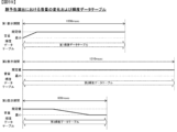
第1期間と、該第1期間後の第2期間と、該第2期間後の期間であって、演出結果として有利態様または不利態様のいずれか一方の態様を報知する第3期間と、を含み、
前記演出実行手段は、
前記第1表示領域において、前記演出動画を表示可能であり、
前記第2表示領域において、遊技に関する情報表示を表示可能であり、
前記第1期間において、前記第1表示領域に第1速度で進行する演出態様の前記演出動画を表示しつつ、前記情報表示を前記第2表示領域に表示可能であり、
前記第2期間において、前記第1表示領域に第1速度よりも遅い第2速度で進行する演出態様の前記演出動画を表示しつつ、前記情報表示を前記第2表示領域に表示可能であり、
前記第3期間において、
演出結果として有利態様を報知する場合、前記第2期間において前記第2表示領域に表示していた前記情報表示を表示せずに、前記第1表示領域と前記第2表示領域とを用いて該有利態様の演出結果を報知可能であり、
演出結果として不利態様を報知する場合、前記第2期間において前記第2表示領域に表示していた前記情報表示を表示した状態で、前記第1表示領域を用いて該不利態様の演出結果を報知可能であり、
前記第1期間と前記第2期間とのいずれにおいても、前記発光手段の発光態様を変化させることが可能であるとともに、前記第2期間において、前記第1期間よりも短い間隔で前記発光手段の発光態様を変化させることが可能であり、
複数のキャラクタが群となって進行する画像を表示する群演出を実行可能であり、
前記群演出における画像の表示期間は、第1表示期間と、第2表示期間と、第3表示期間と、を含み、
前記第1表示期間は、前記群演出において最初のキャラクタの表示を開始してから、キャラクタの新たな表示がされ、いずれかのキャラクタの表示が最初に終了するまでの期間であり、
前記第2表示期間は、前記第1表示期間よりも長い期間であって、キャラクタの新たな表示がされ、かつ表示されているキャラクタの表示が終了する状態が継続する期間であり、
前記第3表示期間は、キャラクタの新たな表示がされることなく、表示されているキャラクタの表示が終了する状態が継続する期間であり、
前記第1表示期間において、最初に表示されたキャラクタの一部が表示されている第1状況から、当該最初に表示されたキャラクタの一部が前記第1状況よりも表示され、かつ2番目に表示されたキャラクタの一部が表示された第2状況になり、
互いに演出背景が異なる第1ステージと、第2ステージと、があり、
前記演出実行手段は、
前記第1ステージにおいて前記群演出を実行する場合、所定フレーム数目から該群演出が開始するように、該群演出を実行可能であり、
前記第2ステージにおいて前記群演出を実行する場合、所定フレーム数目とは異なる特定フレーム数目から該群演出が開始するように、該群演出を実行可能であり、
前記第1ステージにおいて前記群演出が実行される場合における前記有利状態に制御される期待度と、前記第2ステージにおいて前記群演出が実行される場合における前記有利状態に制御される期待度と、が異なる、
ことを特徴としている。
この特徴によれば、有利状態に制御されることを遊技者に印象付けることができる。
手段1の遊技機は、
可変表示の表示結果が特定表示結果となったときに遊技者にとって有利な有利状態(たとえば、大当り遊技状態)に制御可能な遊技機(例えば、パチンコ遊技機1)であって、
演出音を出力可能な音出力手段(例えば、スピーカ8L、8R及び音声制御基板13に搭載されている音声合成用IC079SG132、音声データROM079SG133、増幅回路079SG134)と、
演出動画を表示可能な表示手段(例えば、画像表示装置5)と、
前記表示手段にキャラクタの演出動画を表示するともに該キャラクタの演出動画の表示に伴って前記音出力手段により演出音を出力する所定演出(例えば、リーチ演出)を実行可能な演出実行手段(例えば、演出制御用CPU120)と、
複数のキャラクタが群となって進行する画像を表示する群演出(たとえば、群予告演出)を実行する群演出実行手段(たとえば、図47に示す群予告実行処理,図94~図100に示す6人群予告演出)と、
を備え、
前記演出実行手段は、
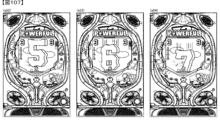
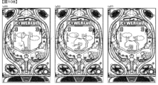
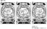
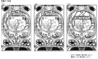
前記所定演出の第1期間において、演出の進行速度が第1速度である演出動画を前記表示手段に表示可能であり(例えば、図10-19~図10-25に示すように、第1リーチ演出、第2リーチ演出、第3リーチ演出、第4リーチ演出のそれぞれの前半部分実行期間中に各リーチ演出の動画が進行速度V1にて画像表示装置5に表示されている部分)、
前記第1期間よりも後の前記所定演出の第2期間において、演出の進行速度が前記第1速度よりも遅い第2速度である演出動画を前記表示手段に表示可能であり(例えば、図10-19~図10-25に示すように、第1リーチ演出、第2リーチ演出、第3リーチ演出、第4リーチ演出のそれぞれの後半部分実行期間中に各リーチ演出の動画が進行速度V2にて画像表示装置5に表示されている部分)、
前記所定演出に対応する演出音については、前記第1期間と前記第2期間とのいずれにおいても、演出音に関する速度を同一速度にて前記音出力手段により出力可能であり(例えば、図10-19~図10-25に示すように、第1リーチ演出、第2リーチ演出、第3リーチ演出、第4リーチ演出のそれぞれの前半部分実行期間中と後半部分実行期間中において、スピーカ8L、8RからBGMや演出音等が通常の再生速度であるV4にて出力されている部分)、
前記群演出における画像の表示期間は、第1表示期間と、第2表示期間と、第3表示期間とを含み(たとえば、図59に示す期間)、
前記第1表示期間は、前記群演出において最初のキャラクタの表示を開始してから、キャラクタの新たな表示がされ、いずれかのキャラクタの表示が最初に終了するまでの期間であり(たとえば、図94(a23)~図96(a30)に示す期間)、
前記第2表示期間は、前記第1表示期間よりも長い期間であって、キャラクタの新たな表示がされ、かつ表示されているキャラクタの表示が終了する状態が継続する期間であり(たとえば、図97(a31)~図98(a36)に示す期間)、
前記第3表示期間は、キャラクタの新たな表示がされることなく、表示されているキャラクタの表示が終了する状態が継続する期間であり(たとえば、図99(a37)~図100(a42)に示す期間)、
前記第1表示期間において、最初に表示されたキャラクタの一部が表示されている第1状況から、当該最初に表示されたキャラクタの一部が前記第1状況よりも表示され、かつ2番目に表示されたキャラクタの一部が表示された第2状況になる(たとえば、図57,図94に示す例)
ことを特徴としている。
この特徴によれば、所定演出の演出動画の進行速度は第1期間と第2期間とで変化するが、所定演出に対応する演出音に関する速度は第1期間と第2期間とで変化しないので、遊技者に対して違和感を与えてしまうことを防止できる。また、より好適に群演出を実行することができる。
The gaming machine of means A is
A gaming machine capable of controlling an advantageous state advantageous to a player when a display result of a variable display becomes a specific display result,
sound output means;
a display means;
A light emitting means;
A performance execution means capable of performing the performance,
Equipped with
The performance execution means is capable of executing a specific performance that suggests that the game is controlled to the advantageous state;
The display means includes a first display area and a second display area closer to the periphery than the first display area,
The specific performance is
The display means displays a performance video, the sound output means outputs performance sound, and the light emitting means emits light,
A first period, a second period after the first period, and a third period after the second period in which either an advantageous aspect or a disadvantageous aspect is announced as a performance result. including,
The performance execution means is
In the first display area, the effect video can be displayed,
In the second display area, information regarding the game can be displayed;
In the first period, the information display can be displayed in the second display area while displaying the effect animation in the effect mode that progresses at a first speed in the first display area,
In the second period, the information display can be displayed in the second display area while displaying the effect animation in the effect mode that progresses at a second speed slower than the first speed in the first display area,
In the third period,
When notifying an advantageous aspect as a performance result, the first display area and the second display area are used to inform the information display that was displayed in the second display area during the second period. It is possible to notify the performance results in an advantageous manner,
When notifying a disadvantageous aspect as a performance result, the first display area is used to notify the disadvantageous performance result while the information display that was displayed in the second display area during the second period is displayed. It is possible and
In both the first period and the second period, it is possible to change the light emitting mode of the light emitting means, and in the second period, the light emitting means may be emitted at shorter intervals than in the first period. It is possible to change the light emission mode,
It is possible to perform a group effect that displays an image of multiple characters progressing as a group,
The image display period in the group effect includes a first display period, a second display period, and a third display period,
The first display period is a period from when the display of the first character starts in the group presentation until a new character is displayed and when the display of one of the characters ends first,
The second display period is a period longer than the first display period, and is a period in which a new character is displayed and the display of the currently displayed character continues to end,
The third display period is a period in which the display of the currently displayed character continues without any new display of the character;
In the first display period, from a first situation in which a part of the initially displayed character is displayed, the part of the initially displayed character is displayed more than in the first situation, and in the second situation. A second situation appears in which part of the displayed character is displayed,
There is a first stage and a second stage with different production backgrounds,
The performance execution means is
When executing the group effect in the first stage, the group effect can be executed such that the group effect starts from a predetermined number of frames;
When executing the group effect in the second stage, the group effect can be executed such that the group effect starts from a specific number of frames different from a predetermined number of frames;
the degree of expectation that is controlled to the advantageous state when the group effect is executed in the first stage; the degree of expectation that is controlled to the advantageous state when the group effect is executed in the second stage; are different,
It is characterized by
According to this feature, it is possible to impress on the player that the control is in an advantageous state.
The gaming machine of
A gaming machine (for example, a pachinko gaming machine 1) that can be controlled to an advantageous state (for example, a jackpot gaming state) that is advantageous for a player when a display result of a variable display becomes a specific display result,
A sound output means capable of outputting performance sounds (for example, a voice synthesis IC079SG132, an audio data ROM079SG133, and an amplifier circuit 079SG134 mounted on the
Display means (for example, image display device 5) capable of displaying a directed video;
A performance execution means (for example, Production control CPU 120),
A group effect execution means (for example, a group preview execution process shown in FIG. 47, a group preview execution process shown in FIGS. 94 to 100) that executes a group effect (for example, a group preview effect) that displays an image in which a plurality of characters advance as a group. Crowd preview performance) and
Equipped with
The performance execution means is
During the first period of the predetermined performance, a performance video in which the progress speed of the performance is a first speed can be displayed on the display means (for example, as shown in FIGS. 10-19 to 10-25, a first reach During the execution period of the first half of each of the performance, the second reach performance, the third reach performance, and the fourth reach performance, the video of each reach performance is displayed on the
In a second period of the predetermined performance after the first period, a performance video in which the performance progresses at a second speed slower than the first speed can be displayed on the display means (for example, in FIG. -19 ~ As shown in Figure 10-25, the video of each reach effect reaches the progress speed V2 during the execution period of the second half of each of the first reach effect, second reach effect, third reach effect, and fourth reach effect. (the part displayed on the image display device 5),
Regarding the effect sound corresponding to the predetermined effect, the speed related to the effect sound can be output by the sound output means at the same speed in both the first period and the second period (for example, in FIG. 19 to FIG. 10-25, during the first half execution period and the second half execution period of each of the first reach performance, second reach performance, third reach performance, and fourth reach performance, the
The display period of images in the group effect includes a first display period, a second display period, and a third display period (for example, the period shown in FIG. 59),
The first display period is a period from when the display of the first character starts in the group presentation until a new character is displayed and when the display of one of the characters ends for the first time (for example, 94 (a23) to the period shown in FIG. 96 (a30)),
The second display period is a period longer than the first display period, and is a period in which a new character is displayed and the display of the currently displayed character continues (for example, when 97 (a31) to the period shown in FIG. 98 (a36)),
The third display period is a period in which the display of the currently displayed character continues without any new display of the character (for example, as shown in FIG. 99 (a37) to FIG. 100 (a42) period),
In the first display period, from a first situation in which a part of the initially displayed character is displayed, the part of the initially displayed character is displayed more than in the first situation, and in the second situation. A second situation occurs in which a part of the displayed character is displayed (for example, the examples shown in FIGS. 57 and 94)
It is characterized by
According to this feature, although the progress speed of the performance video of the predetermined performance changes between the first period and the second period, the speed of the performance sound corresponding to the predetermined performance does not change between the first period and the second period. , it is possible to prevent players from feeling uncomfortable. In addition, it is possible to execute group effects more suitably.
また、後述する発明を実施するための形態には、以下の手段2の遊技機に係る発明が含まれる。従来より、遊技機において、特開2019-050851号公報に示されているような、複数のキャラクタやオブジェクトの画像が登場する群演出を実行可能なものがあった。しかしながら、このような遊技機にあっては、群演出を実行することで遊技に面白みを享受させることができるが、このような群演出に関してはまだまだ改良の余地があり、この点に鑑み、より好適に群演出を実行することができる遊技機の提供が求められている。
Further, the embodiments for carrying out the invention described below include the invention related to the gaming machine of
手段2の遊技機は、
可変表示の表示結果が特定表示結果となったときに遊技者にとって有利な有利状態(たとえば、大当り遊技状態)に制御可能な遊技機(たとえば、パチンコ遊技機1)であって、
複数のキャラクタが群となって進行する画像を表示する群演出(たとえば、群予告演出)を実行する群演出実行手段(たとえば、図47に示す群予告実行処理,図94~図100に示す6人群予告演出)を備え、
前記群演出における画像の表示期間は、第1表示期間と、第2表示期間と、第3表示期間とを含み(たとえば、図59に示す期間)、
前記第1表示期間は、前記群演出において最初のキャラクタの表示を開始してから、キャラクタの新たな表示がされ、いずれかのキャラクタの表示が最初に終了するまでの期間であり(たとえば、図94(a23)~図96(a30)に示す期間)、
前記第2表示期間は、前記第1表示期間よりも長い期間であって、キャラクタの新たな表示がされ、かつ表示されているキャラクタの表示が終了する状態が継続する期間であり(たとえば、図97(a31)~図98(a36)に示す期間)、
前記第3表示期間は、キャラクタの新たな表示がされることなく、表示されているキャラクタの表示が終了する状態が継続する期間であり(たとえば、図99(a37)~図100(a42)に示す期間)、
前記第1表示期間において、最初に表示されたキャラクタの一部が表示されている第1状況から、当該最初に表示されたキャラクタの一部が前記第1状況よりも表示され、かつ2番目に表示されたキャラクタの一部が表示された第2状況になる(たとえば、図57,図94に示す例)
ことを特徴としている。
このような構成によれば、より好適に群演出を実行することができる。
The gaming machine of
A gaming machine (for example, a pachinko gaming machine 1) that can be controlled to an advantageous state (for example, a jackpot gaming state) that is advantageous to a player when a display result of a variable display becomes a specific display result,
A group effect execution means (for example, a group preview execution process shown in FIG. 47, a group preview execution process shown in FIGS. 94 to 100) that executes a group effect (for example, a group preview effect) that displays an image in which a plurality of characters advance as a group. Equipped with a crowd preview performance),
The display period of images in the group effect includes a first display period, a second display period, and a third display period (for example, the period shown in FIG. 59),
The first display period is a period from when the display of the first character starts in the group presentation until a new character is displayed and when the display of one of the characters ends for the first time (for example, 94 (a23) to the period shown in FIG. 96 (a30)),
The second display period is a period longer than the first display period, and is a period in which a new character is displayed and the display of the currently displayed character continues (for example, when 97 (a31) to the period shown in FIG. 98 (a36)),
The third display period is a period in which the display of the currently displayed character continues without any new display of the character (for example, as shown in FIG. 99 (a37) to FIG. 100 (a42) period),
In the first display period, from a first situation in which a part of the initially displayed character is displayed, the part of the initially displayed character is displayed more than in the first situation, and in the second situation. A second situation occurs in which a part of the displayed character is displayed (for example, the examples shown in FIGS. 57 and 94)
It is characterized by
According to such a configuration, group effects can be executed more suitably.
尚、本発明は、本発明の請求項に記載された発明特定事項のみを有するものであって良いし、本発明の請求項に記載された発明特定事項とともに該発明特定事項以外の構成を有するものであっても良い。 Note that the present invention may have only the matters specifying the invention described in the claims of the present invention, or may have configurations other than the matters specifying the invention together with the matters specifying the invention described in the claims of the present invention. It may be something.
本発明に係る遊技機であるパチンコ遊技機を実施するための形態を実施例に基づいて以下に説明する。 DESCRIPTION OF THE PREFERRED EMBODIMENTS A form for implementing a pachinko gaming machine, which is a gaming machine according to the present invention, will be described below based on an example.
[形態]
形態1の遊技機は、
遊技が可能な遊技機(例えば、パチンコ遊技機1)であって、
演出音を出力可能な音出力手段(例えば、スピーカ8L、8R及び音声制御基板13に搭載されている音声合成用IC079SG132、音声データROM079SG133、増幅回路079SG134)と、
演出動画を表示可能な表示手段(例えば、画像表示装置5)と、
前記表示手段にキャラクタの演出動画を表示するともに該キャラクタの演出動画の表示に伴って前記音出力手段により演出音を出力する所定演出(例えば、リーチ演出)を実行可能な演出実行手段(例えば、演出制御用CPU120)と、
を備え、
前記演出実行手段は、
前記所定演出の第1期間において、演出の進行速度が第1速度である演出動画を前記表示手段に表示可能であり(例えば、図10-19~図10-25に示すように、第1リーチ演出、第2リーチ演出、第3リーチ演出、第4リーチ演出のそれぞれの前半部分実行期間中に各リーチ演出の動画が進行速度V1にて画像表示装置5に表示されている部分)、
前記第1期間よりも後の前記所定演出の第2期間において、演出の進行速度が前記第1速度よりも遅い第2速度である演出動画を前記表示手段に表示可能であり(例えば、図10-19~図10-25に示すように、第1リーチ演出、第2リーチ演出、第3リーチ演出、第4リーチ演出のそれぞれの後半部分実行期間中に各リーチ演出の動画が進行速度V2にて画像表示装置5に表示されている部分)、
前記所定演出に対応する演出音については、前記第1期間と前記第2期間とのいずれにおいても、演出音に関する速度を同一速度にて前記音出力手段により出力可能である(例えば、図10-19~図10-25に示すように、第1リーチ演出、第2リーチ演出、第3リーチ演出、第4リーチ演出のそれぞれの前半部分実行期間中と後半部分実行期間中において、スピーカ8L、8RからBGMや演出音等が通常の再生速度であるV4にて出力されている部分)
ことを特徴としている。
この特徴によれば、所定演出の演出動画の進行速度は第1期間と第2期間とで変化するが、所定演出に対応する演出音に関する速度は第1期間と第2期間とで変化しないので、遊技者に対して違和感を与えてしまうことを防止できる。
[form]
A gaming machine (for example, pachinko gaming machine 1) capable of playing games,
A sound output means capable of outputting performance sounds (for example, a voice synthesis IC079SG132, an audio data ROM079SG133, and an amplifier circuit 079SG134 mounted on the
Display means (for example, image display device 5) capable of displaying a directed video;
A performance execution means (for example, Production control CPU 120),
Equipped with
The performance execution means is
During the first period of the predetermined performance, a performance video in which the progress speed of the performance is a first speed can be displayed on the display means (for example, as shown in FIGS. 10-19 to 10-25, a first reach During the execution period of the first half of each of the performance, the second reach performance, the third reach performance, and the fourth reach performance, the video of each reach performance is displayed on the
In a second period of the predetermined performance after the first period, a performance video in which the performance progresses at a second speed slower than the first speed can be displayed on the display means (for example, in FIG. -19 ~ As shown in Figure 10-25, the video of each reach effect reaches the progress speed V2 during the execution period of the second half of each of the first reach effect, second reach effect, third reach effect, and fourth reach effect. (the part displayed on the image display device 5),
Regarding the effect sound corresponding to the predetermined effect, the speed related to the effect sound can be output by the sound output means at the same speed in both the first period and the second period (for example, in FIG. 19 to FIG. 10-25, during the first half execution period and the second half execution period of each of the first reach performance, second reach performance, third reach performance, and fourth reach performance, the
It is characterized by
According to this feature, although the progress speed of the performance video of the predetermined performance changes between the first period and the second period, the speed of the performance sound corresponding to the predetermined performance does not change between the first period and the second period. , it is possible to prevent players from feeling uncomfortable.
形態2の遊技機は、形態1に記載の遊技機であって、
前記音出力手段は、音を再生する再生回路(例えば、音声合成用IC079SG132)と、該再生回路で再生された音を増幅する増幅回路(例えば、増幅回路079SG134)と、該増幅回路で増幅された音を出力するスピーカ(例えば、スピーカ8L、8R)と、を含む
ことを特徴としている。
この特徴によれば、再現性の高い演出音を適切な音量にてスピーカから出力することができる。
The gaming machine of
The sound output means includes a reproduction circuit for reproducing sound (for example, IC079SG132 for voice synthesis), an amplification circuit for amplifying the sound reproduced by the reproduction circuit (for example, amplification circuit 079SG134), and a sound that is amplified by the amplification circuit. The device is characterized in that it includes speakers (for example,
According to this feature, highly reproducible performance sound can be output from the speaker at an appropriate volume.
形態3の遊技機は、形態1または形態2に記載の遊技機であって、
前記演出実行手段は、前記所定演出に対応する演出音に関する速度を、前記第2期間における所定期間において前記第1期間と同一速度で前記音出力手段により出力可能であり、前記第2期間における所定期間よりも後の特定期間において前記第1期間とは異なる速度で前記音出力手段により出力可能である(例えば、変形例079SG-1に示すように、第1リーチ演出、第2リーチ演出、第3リーチ演出、第4リーチ演出の各リーチ演出後半部分実行期間の前半部においては1リーチ演出、第2リーチ演出、第3リーチ演出、第4リーチ演出の各リーチ演出前半部分実行期間と同じくスピーカ8L、8Rから再生速度V4にて演出音を出力する一方で、第1リーチ演出、第2リーチ演出、第3リーチ演出、第4リーチ演出の各リーチ演出後半部分実行期間の後半部においてはV4とは異なる再生速度(例えば、再生速度V4よりも遅いV5)にて演出音を出力する部分)
ことを特徴としている。
この特徴によれば、演出動画が第2速度で表示されている第2期間の内、特定期間については演出音に関する速度が異なるようできるため、所定演出に対応する演出音による演出効果を向上できるので、遊技興趣を向上できる。
The gaming machine of
The performance execution means is capable of outputting a speed related to a performance sound corresponding to the predetermined performance by the sound output means during a predetermined period in the second period at the same speed as in the first period; In a specific period after the period, the sound output means can output at a speed different from the first period (for example, as shown in modification 079SG-1, the first reach effect, the second reach effect, the second reach effect, etc.) can be output at a speed different from the first period. In the first half of the execution period of the second half of each reach performance of the 3rd reach performance and the 4th reach performance, the speaker is used as in the first half of the execution period of each reach performance of the 1st reach performance, the 2nd reach performance, the 3rd reach performance, and the 4th reach performance. While the production sound is output from 8L and 8R at the playback speed V4, in the second half of the execution period of the second half of each reach production of the 1st reach production, 2nd reach production, 3rd reach production, and 4th reach production, the playback speed is V4. (For example, the part where the production sound is output at a playback speed different from the playback speed V4 (for example, playback speed V5 slower than V4)
It is characterized by
According to this feature, the speed of the effect sound can be made different for a specific period within the second period in which the effect video is displayed at the second speed, so it is possible to improve the effect of the effect of the effect sound corresponding to the predetermined effect. Therefore, it is possible to improve the interest in the game.
形態4の遊技機は、形態1~形態3のいずれかに記載の遊技機であって、
前記所定演出に対応する演出音は、楽曲と効果音とを含む(例えば、スピーカ8L、8RからBGM(楽曲)や効果音を出力可能な部分)
この特徴によれば、楽曲と効果音とを含む演出音によって遊技興趣を向上できる。
The gaming machine of
The production sound corresponding to the predetermined production includes music and sound effects (for example, a portion where BGM (music) and sound effects can be output from the
According to this feature, it is possible to improve the game's interest through the performance sound including music and sound effects.
形態5の遊技機は、形態1~形態4のいずれかに記載の遊技機であって、
少なくとも前記第1期間と前記第2期間とで発光可能であって発光態様を変化可能な発光手段(例えば、遊技効果ランプ9)を備え、
前記演出実行手段は、前記第2期間において前記第1期間よりも短い周期で前記発光手段の発光態様を変化可能である(例えば、図10-20、図10-21、図10-24、図10-25に示すように、第2リーチ演出後半部分実行期間中や第4リーチ演出後半部分実行期間中において、第1リーチ演出、第2リーチ演出、第3リーチ演出の各実行期間及び第4リーチ演出前半部分実行期間よりも短い周期で遊技効果ランプ9が点滅する部分)
ことを特徴としている。
この特徴によれば、発光手段の発光態様の変化周期が、演出の進行速度が遅い第2期間において逆に短く(早く)なることによって、第2期間の演出効果を向上できる。
The gaming machine of
comprising a light emitting means (for example, a game effect lamp 9) capable of emitting light and changing the light emission mode at least in the first period and the second period;
The effect execution means is capable of changing the light emitting mode of the light emitting means in the second period at a shorter cycle than the first period (for example, in FIGS. 10-20, 10-21, 10-24, As shown in 10-25, during the execution period of the second half of the second reach performance and the second half of the fourth reach performance, each execution period of the first reach performance, the second reach performance, the third reach performance and the fourth reach performance (The part where the
It is characterized by
According to this feature, the change cycle of the light emitting mode of the light emitting means becomes shorter (faster) in the second period when the speed of progress of the performance is slow, thereby improving the performance effect of the second period.
形態6の遊技機は、形態1~形態5のいずれかに記載の遊技機であって、
識別情報の可変表示を実行可能であり、遊技が可能な遊技機(例えば、パチンコ遊技機1)であって、
演出音を出力可能な音出力手段(例えば、スピーカ8L、8R及び音声制御基板13に搭載されている音声合成用IC079SG132、音声データROM079SG133、増幅回路079SG134)と、
演出動画を表示可能な表示領域として、第1表示領域(例えば、図10-2(A)に示す第1表示領域079SG005F)と、該第1表示領域よりも周縁寄りの第2表示領域(例えば、第2表示領域079SG005Sa)と、を含む表示手段(例えば、画像表示装置5)と、
前記第1表示領域にキャラクタの演出動画を表示するともに該キャラクタの演出動画の表示に伴って前記音出力手段により演出音を出力する所定演出(例えば、リーチ演出)と、前記第2表示領域において可変表示に関連した情報表示を動作させる情報演出(例えば、図10-2(B)に示す第1保留記憶表示エリア079SG005D及び第2保留記憶表示エリア079SG005Uにおける保留表示の回転表示や、図10-2(C)に示すテロップ表示エリア079SG005Tにおけるテロップの移動表示)を実行可能な演出実行手段(例えば、演出制御用CPU120)と、
を備え、
前記演出実行手段は、
前記所定演出の第1期間において、演出の進行速度が第1速度である演出動画を前記表示手段に表示可能であり(例えば、図10-19~図10-25に示すように、第1リーチ演出、第2リーチ演出、第3リーチ演出、第4リーチ演出のそれぞれの前半部分実行期間中に各リーチ演出の動画が進行速度V1にて画像表示装置5に表示されている部分)、
前記第1期間よりも後の前記所定演出の第2期間において、演出の進行速度が前記第1速度よりも遅い第2速度である演出動画を前記表示手段に表示可能であり(例えば、図10-19~図10-25に示すように、第1リーチ演出、第2リーチ演出、第3リーチ演出、第4リーチ演出のそれぞれの後半部分実行期間中に各リーチ演出の動画が進行速度V2にて画像表示装置5に表示されている部分)、
前記所定演出に対応する演出音については、前記第1期間と前記第2期間とのいずれにおいても、演出音に関する速度を同一速度にて前記音出力手段により出力可能であり(例えば、図10-19~図10-25に示すように、第1リーチ演出、第2リーチ演出、第3リーチ演出、第4リーチ演出のそれぞれの前半部分実行期間中と後半部分実行期間中において、スピーカ8L、8RからBGMや演出音等が通常の再生速度であるV4にて出力されている部分)、
前記情報演出については、前記第1期間と前記第2期間とのいずれにおいても、前記情報表示を同一の動作速度で動作させる情報演出を実行可能である(例えば、図10-19~図10-25に示すように、第1リーチ演出、第2リーチ演出、第3リーチ演出、第4リーチ演出のそれぞれの前半部分実行期間中と後半部分実行期間中において、保留表示の回転表示を回転速度V3、テロップの移動表示を移動速度V3で表示する部分)
ことを特徴としている。
この特徴によれば、所定演出の演出動画の進行速度は第1期間と第2期間とで変化するが、情報表示の動作速度と所定演出に対応する演出音に関する速度は第1期間と第2期間とで変化しないので、遊技者に対して違和感を与えてしまうことを防止できる。
The gaming machine of
A gaming machine (for example, a pachinko gaming machine 1) capable of displaying identification information in a variable manner and capable of playing games,
A sound output means capable of outputting performance sounds (for example, a voice synthesis IC079SG132, an audio data ROM079SG133, and an amplifier circuit 079SG134 mounted on the
The display areas that can display the effect animation include a first display area (for example, the first display area 079SG005F shown in FIG. 10-2(A)) and a second display area that is closer to the periphery than the first display area (for example, , second display area 079SG005Sa);
A predetermined effect (e.g., reach effect) in which an effect animation of a character is displayed in the first display area and an effect sound is outputted by the sound output means in conjunction with the display of the effect animation of the character; Information display that operates the information display related to the variable display (for example, rotating display of the pending display in the first pending storage display area 079SG005D and the second pending storage display area 079SG005U shown in FIG. 10-2(B), 2(C); moving display of the telop in the telop display area 079SG005T);
Equipped with
The performance execution means is
During the first period of the predetermined performance, a performance video in which the progress speed of the performance is a first speed can be displayed on the display means (for example, as shown in FIGS. 10-19 to 10-25, a first reach During the execution period of the first half of each of the performance, the second reach performance, the third reach performance, and the fourth reach performance, the video of each reach performance is displayed on the
In a second period of the predetermined performance after the first period, a performance video in which the performance progresses at a second speed slower than the first speed can be displayed on the display means (for example, in FIG. -19 ~ As shown in Figure 10-25, the video of each reach effect reaches the progress speed V2 during the execution period of the second half of each of the first reach effect, second reach effect, third reach effect, and fourth reach effect. (the part displayed on the image display device 5),
Regarding the effect sound corresponding to the predetermined effect, the speed related to the effect sound can be output by the sound output means at the same speed in both the first period and the second period (for example, in FIG. 19 to FIG. 10-25, during the first half execution period and the second half execution period of each of the first reach performance, second reach performance, third reach performance, and fourth reach performance, the
Regarding the information presentation, it is possible to perform an information presentation in which the information display operates at the same operating speed in both the first period and the second period (for example, in FIGS. 10-19 to 10- 25, during the first half execution period and the second half execution period of each of the first reach effect, second reach effect, third reach effect, and fourth reach effect, the rotating display of the hold display is rotated at the rotation speed V3. , the part where the movement of the caption is displayed at the movement speed V3)
It is characterized by
According to this feature, the progress speed of the performance video of the predetermined performance changes between the first period and the second period, but the operating speed of the information display and the speed of the performance sound corresponding to the predetermined performance change between the first period and the second period. Since it does not change from period to period, it is possible to prevent the player from feeling uncomfortable.
形態7の遊技機は、形態6に記載の遊技機であって、
前記第1表示領域の総面積は、前記第2表示領域の総面積よりも大きい(例えば、図10-2(A)に示すように、第1表示領域079SG005Fの面積は、第2表示領域079SG005Saの面積と第3表示領域079SG005Sbとを合わせた面積よりも広い部分)
ことを特徴としている。
この特徴によれば、遊技者が所定演出を情報演出よりも認識し易くできるので、遊技興趣を向上できる。
The gaming machine of
The total area of the first display area is larger than the total area of the second display area (for example, as shown in FIG. 10-2(A), the area of the first display area 079SG005F is larger than the area of the second display area 079SG005Sa). (a portion wider than the combined area of the area and the third display area 079SG005Sb)
It is characterized by
According to this feature, it is possible for the player to more easily recognize the predetermined presentation than the information presentation, thereby improving the player's enjoyment of the game.
形態8の遊技機は、形態6または形態7に記載の遊技機であって、
前記演出実行手段は、前記第1期間と前記第2期間以外の少なくとも可変表示中の期間においては、常に同一の動作速度で前記情報表示を動作させる情報演出を実行可能である(例えば、図10-18~図10-25に示すように、リーチ演出中以外の期間において、第1保留記憶表示エリア079SG005D及び第2保留記憶表示エリア079SG005Uでは保留表示の回転表示が回転速度V3で実行され、テロップ表示エリア079SG005Tではテロップの移動表示が移動速度V3で実行される部分)
ことを特徴としている。
この特徴によれば、情報表示の動作速度が変化することがないので、遊技者が情報演出を認識し難くなってしまうことを防止できる。
The gaming machine of
The effect execution means is capable of executing an information effect in which the information display always operates at the same operating speed during at least a variable display period other than the first period and the second period (for example, as shown in FIG. -18 to Figure 10-25, during the period other than during the reach effect, the rotating display of the pending display is executed at rotation speed V3 in the first pending memory display area 079SG005D and the second pending memory display area 079SG005U, and the telop In display area 079SG005T, the moving display of the caption is executed at movement speed V3)
It is characterized by
According to this feature, since the operating speed of information display does not change, it is possible to prevent the player from becoming difficult to recognize the information presentation.
形態9の遊技機は、形態6~形態8のいずれかに記載の遊技機であって、
前記情報演出は、実行中の可変表示における演出に関する状態を示唆する情報表示を前記第2表示領域に順次移動表示させる移動表示演出(例えば、テロップ表示エリア079SG005Tにおいて遊技状態に応じたメッセージの移動表示を実行する部分)を含み、
前記演出実行手段は、前記情報表示の少なくとも一部が常に遊技者から視認可能となるように該情報表示を移動表示させる移動表示演出を実行可能である(例えば、図10-2(C)に示すように、テロップ表示エリア079SG005Tにおいてメッセージに含まれる文字は、該テロップ表示エリア079SG005Tの右端部に到達して表示が終了すると同時に該テロップ表示エリア079SG005Tの左端部にて再度表示されて再び左方向から右方向に向けて移動される部分)
ことを特徴としている。
この特徴によれば、情報表示の少なくとも一部が常に遊技者から視認可能となるので、移動表示演出が実行されていることを遊技者が認識し易くできる。
The gaming machine of
The information presentation is a moving display presentation that sequentially moves and displays information indicating the state of the presentation in the variable display being executed in the second display area (for example, a moving display of a message according to the gaming state in the telop display area 079SG005T). ),
The effect execution means is capable of executing a moving display effect that moves and displays the information display so that at least a part of the information display is always visible to the player (for example, as shown in FIG. 10-2(C)). As shown, the characters included in the message in the telop display area 079SG005T reach the right end of the telop display area 079SG005T and end the display, and at the same time they are displayed again at the left end of the telop display area 079SG005T and move to the left again. (the part that is moved towards the right)
It is characterized by
According to this feature, since at least a part of the information display is always visible to the player, it is possible for the player to easily recognize that the moving display effect is being executed.
形態10の遊技機は、形態1~形態9のいずれかに記載の遊技機であって、
遊技が可能な遊技機(例えば、パチンコ遊技機1)であって、
演出音を出力可能な音出力手段例えば、スピーカ8L、8R及び音声制御基板13に搭載されている音声合成用IC079SG132、音声データROM079SG133、増幅回路079SG134)と、
演出動画を表示可能な表示手段(例えば、画像表示装置5)と、
特典(例えば、大当り遊技状態)を付与する特典付与手段(例えば、CPU103)と、
前記表示手段にキャラクタの演出動画を表示するともに該キャラクタの演出動画の表示に伴って前記音出力手段により演出音を出力することで特典が付与されることを示唆する所定演出(例えば、リーチ演出)と、該所定演出の実行後に特典が付与されるか否かを報知する報知演出(例えば、大当り報知演出とはずれ報知演出)とを実行可能な演出実行手段(例えば、演出制御用CPU120)と、
を備え、
前記演出実行手段は、
前記所定演出の第1期間において、演出の進行速度が第1速度である演出動画を前記表示手段に表示可能であり(例えば、図10-19~図10-25に示すように、第1リーチ演出、第2リーチ演出、第3リーチ演出、第4リーチ演出のそれぞれの前半部分実行期間中に各リーチ演出の動画が進行速度V1にて画像表示装置5に表示されている部分)、
前記第1期間よりも後の前記所定演出の第2期間において、演出の進行速度が前記第1速度よりも遅い第2速度である演出動画を前記表示手段に表示可能であり(例えば、図10-19~図10-25に示すように、第1リーチ演出、第2リーチ演出、第3リーチ演出、第4リーチ演出のそれぞれの後半部分実行期間中に各リーチ演出の動画が進行速度V2にて画像表示装置5に表示されている部分)、
前記所定演出に対応する演出音については、前記第1期間と前記第2期間とのいずれにおいても、演出音に関する速度を同一速度にて前記音出力手段により出力可能であり(例えば、図10-19~図10-25に示すように、第1リーチ演出、第2リーチ演出、第3リーチ演出、第4リーチ演出のそれぞれの前半部分実行期間中と後半部分実行期間中において、スピーカ8L、8RからBGMや演出音等が通常の再生速度であるV4にて出力されている部分)、
前記第2期間内においては、前記所定演出とは異なる演出であって該所定演出の演出効果を高めるための効果演出を実行可能である(例えば、図10-20、図10-21、及び図10-28に示すように、第2リーチ演出後半部分実行期間において画像表示装置5に集中線を表示する効果演出を実行する部分)
ことを特徴としている。
この特徴によれば、所定演出の演出動画の進行速度は第1期間と第2期間とで変化するが、所定演出に対応する演出音に関する速度は第1期間と第2期間とで変化しないので、遊技者に対して違和感を与えてしまうことを防止でき、更に、第2期間の演出効果を高めるとともに、第2期間が終了して報知演出が実行されることを効果演出によって遊技者が認識し易くできる。
The gaming machine of
A gaming machine (for example, pachinko gaming machine 1) capable of playing games,
Sound output means capable of outputting performance sounds (for example, a voice synthesis IC079SG132, an audio data ROM079SG133, an amplifier circuit 079SG134) mounted on the
Display means (for example, image display device 5) capable of displaying a directed video;
A benefit granting means (for example, CPU 103) that grants a benefit (for example, a jackpot gaming state);
A predetermined effect (for example, a reach effect) indicating that a privilege will be given by displaying a performance video of a character on the display means and outputting a performance sound by the sound output means in conjunction with the display of the performance video of the character. ), and a performance execution means (for example, a performance control CPU 120) capable of executing a notification performance (for example, a jackpot notification performance and a loss notification performance) that informs whether or not a privilege will be awarded after the execution of the predetermined performance. ,
Equipped with
The performance execution means is
During the first period of the predetermined performance, a performance video in which the progress speed of the performance is a first speed can be displayed on the display means (for example, as shown in FIGS. 10-19 to 10-25, a first reach During the execution period of the first half of each of the performance, the second reach performance, the third reach performance, and the fourth reach performance, the video of each reach performance is displayed on the
In a second period of the predetermined performance after the first period, a performance video in which the performance progresses at a second speed slower than the first speed can be displayed on the display means (for example, in FIG. -19 ~ As shown in Figure 10-25, the video of each reach effect reaches the progress speed V2 during the execution period of the second half of each of the first reach effect, second reach effect, third reach effect, and fourth reach effect. (the part displayed on the image display device 5),
Regarding the effect sound corresponding to the predetermined effect, the speed related to the effect sound can be output by the sound output means at the same speed in both the first period and the second period (for example, in FIG. 19 to FIG. 10-25, during the first half execution period and the second half execution period of each of the first reach performance, second reach performance, third reach performance, and fourth reach performance, the
Within the second period, it is possible to perform an effect production that is different from the predetermined production and that enhances the production effect of the predetermined production (for example, as shown in FIGS. 10-20, 10-21, and As shown in 10-28, the part that executes the effect production of displaying concentrated lines on the
It is characterized by
According to this feature, although the progress speed of the performance video of the predetermined performance changes between the first period and the second period, the speed of the performance sound corresponding to the predetermined performance does not change between the first period and the second period. , it is possible to prevent players from feeling uncomfortable, and furthermore, to enhance the performance effect of the second period, and to make the players aware that the second period has ended and the notification performance will be executed through the effect performance. It's easy to do.
形態11の遊技機は、形態10に記載の遊技機であって、
前記演出実行手段は、
前記効果演出を、前記所定演出の演出効果を高める効果度が異なる複数の態様(例えば、図10-28(C)に示す集中線が表示される態様と、図10-28(D)に示すように、図10-28(C)よりも集中線の表示数が多い態様)にて実行可能であり、
前記第2期間の始点から終点に進むに伴って、演出効果を高める効果度が順次高くなる態様の前記効果演出を実行可能である(例えば、図10-28(C)及び図10-28(D)に示すように、バトル演出の進行に伴って集中線の表示数が多くなる部分)
ことを特徴としている。
この特徴によれば、効果演出の態様が、所定演出の演出効果を高める効果度が順次高くなる態様に変化するので、第2期間が終了して報知演出が実行されることを効果演出によって遊技者が一層認識し易くできる。
The gaming machine of
The performance execution means is
The effect production may be performed in a plurality of modes with different degrees of effectiveness for enhancing the production effect of the predetermined production (for example, a mode in which concentrated lines are displayed as shown in FIG. 10-28(C), and a mode as shown in FIG. 10-28(D)). As shown in FIG.
As the second period progresses from the start point to the end point, it is possible to execute the effect production in a manner in which the degree of effectiveness of enhancing the production effect increases sequentially (for example, FIG. 10-28(C) and FIG. 10-28( As shown in D), the number of concentrated lines increases as the battle progresses.)
It is characterized by
According to this feature, since the mode of the effect production changes to a mode in which the degree of effectiveness of enhancing the production effect of the predetermined production increases sequentially, the effect production notifies the player that the notification production will be executed when the second period ends. This makes it easier for people to recognize the information.
形態12の遊技機は、形態1~形態11のいずれかに記載の遊技機であって、
識別情報の可変表示を実行可能であり、遊技が可能な遊技機(例えば、パチンコ遊技機1)であって、
演出音を出力可能な音出力手段(例えば、スピーカ8L、8R及び音声制御基板13に搭載されている音声合成用IC079SG132、音声データROM079SG133、増幅回路079SG134)と、
演出動画を表示可能な表示領域として、第1表示領域(例えば、図10-2(A)に示す第1表示領域079SG005F)と、該第1表示領域よりも周縁寄りの第2表示領域(例えば、第2表示領域079SG005Sa)と、を含む表示手段(例えば、画像表示装置5)と、
特典(例えば、大当り遊技状態)を付与する特典付与手段(例えば、CPU103)と、
前記第1表示領域にキャラクタの演出動画を表示するともに該キャラクタの演出動画の表示に伴って前記音出力手段により演出音を出力することで特典が付与されることを示唆する所定演出(例えば、リーチ演出)と、該所定演出の実行後に特典が付与されるか否かを報知する報知演出(例えば、大当り報知演出とはずれ報知演出)と、前記第2表示領域において可変表示に関連した特定情報演出(例えば、図10-2(B)に示す第1保留記憶表示エリア079SG005D及び第2保留記憶表示エリア079SG005Uにおける保留表示の回転表示や、図10-2(C)に示すテロップ表示エリア079SG005Tにおけるテロップの移動表示)を実行可能な演出実行手段(例えば、演出制御用CPU120)と、
を備え、
前記演出実行手段は、
前記所定演出の第1期間において、演出の進行速度が第1速度である演出動画を前記第1表示領域に表示可能であり(例えば、図10-19~図10-25に示すように、第1リーチ演出、第2リーチ演出、第3リーチ演出、第4リーチ演出のそれぞれの前半部分実行期間中に各リーチ演出の動画が進行速度V1にて画像表示装置5に表示されている部分)、
前記第1期間よりも後の前記所定演出の第2期間において、演出の進行速度が前記第1速度よりも遅い第2速度である演出動画を前記第1表示領域に表示可能であり(例えば、図10-19~図10-25に示すように、第1リーチ演出、第2リーチ演出、第3リーチ演出、第4リーチ演出のそれぞれの後半部分実行期間中に各リーチ演出の動画が進行速度V2にて画像表示装置5に表示されている部分)、
前記所定演出に対応する演出音については、前記第1期間と前記第2期間とのいずれにおいても、演出音に関する速度を同一速度にて前記音出力手段により出力可能であり(例えば、図10-19~図10-25に示すように、第1リーチ演出、第2リーチ演出、第3リーチ演出、第4リーチ演出のそれぞれの前半部分実行期間中と後半部分実行期間中において、スピーカ8L、8RからBGMや演出音等が通常の再生速度であるV4にて出力されている部分)、
前記報知演出を、前記第1表示領域と前記第2表示領域とにおいて実行可能である(例えば、図10-26(G)、図10-29(E)、図10-30(D)、図10-31(G)、図10-35(C)に示すように、大当り報知演出として飾り図柄が大当りの組み合わせで停止する際に、第1表示領域079SG005Fと第2表示領域079SG005Saとで該大当り報知演出の画像を表示する部分)
ことを特徴としている。
この特徴によれば、所定演出の演出動画の進行速度は第1期間と第2期間とで変化するが、所定演出に対応する演出音に関する速度は第1期間と第2期間とで変化しないので、遊技者に対して違和感を与えてしまうことを防止でき、更に、第1表示領域と第2表示領域とを併せた広い表示領域において報知演出を実行することで、特典が付与されたことを遊技者が認識し易くできる。
The gaming machine of
A gaming machine (for example, a pachinko gaming machine 1) capable of displaying identification information in a variable manner and capable of playing games,
A sound output means capable of outputting performance sounds (for example, a voice synthesis IC079SG132, an audio data ROM079SG133, and an amplifier circuit 079SG134 mounted on the
The display areas that can display the effect animation include a first display area (for example, the first display area 079SG005F shown in FIG. 10-2(A)) and a second display area that is closer to the periphery than the first display area (for example, , second display area 079SG005Sa);
A benefit granting means (for example, CPU 103) that grants a benefit (for example, a jackpot gaming state);
A predetermined effect (for example, a reach effect), a notification effect that informs whether or not a benefit will be awarded after execution of the predetermined effect (for example, a jackpot notification effect and a loss notification effect), and specific information related to the variable display in the second display area. Effects (for example, rotating display of the pending display in the first pending storage display area 079SG005D and second pending storage display area 079SG005U shown in FIG. 10-2(B), or in the telop display area 079SG005T shown in FIG. 10-2(C)) a performance execution means (for example, a performance control CPU 120) capable of executing a moving display of a subtitle;
Equipped with
The performance execution means is
During the first period of the predetermined performance, a performance video whose performance progresses at a first speed can be displayed in the first display area (for example, as shown in FIGS. 10-19 to 10-25, During the execution period of the first half of each of the 1st reach performance, the 2nd reach performance, the 3rd reach performance, and the 4th reach performance, the video of each reach performance is displayed on the
In a second period of the predetermined performance after the first period, a performance video in which the performance progresses at a second speed slower than the first speed can be displayed in the first display area (for example, As shown in Figures 10-19 to 10-25, during the execution period of the second half of each of the 1st reach effect, 2nd reach effect, 3rd reach effect, and 4th reach effect, the progress speed of the video of each reach effect is (portion displayed on the
Regarding the effect sound corresponding to the predetermined effect, the speed related to the effect sound can be output by the sound output means at the same speed in both the first period and the second period (for example, in FIG. 19 to FIG. 10-25, during the first half execution period and the second half execution period of each of the first reach performance, second reach performance, third reach performance, and fourth reach performance, the
The notification effect can be executed in the first display area and the second display area (for example, FIG. 10-26(G), FIG. 10-29(E), FIG. 10-30(D), As shown in FIG. 10-31 (G) and FIG. 10-35 (C), when the decorative symbols stop at a jackpot combination as a jackpot notification effect, the jackpot is displayed in the first display area 079SG005F and the second display area 079SG005Sa. (The part that displays the image of the notification effect)
It is characterized by
According to this feature, although the progress speed of the performance video of the predetermined performance changes between the first period and the second period, the speed of the performance sound corresponding to the predetermined performance does not change between the first period and the second period. , it is possible to prevent the player from feeling uncomfortable, and furthermore, by executing the notification effect in a wide display area that combines the first display area and the second display area, it is possible to notify the player that a privilege has been awarded. It can be easily recognized by players.
形態13は、形態12に記載の遊技機であって、
前記演出実行手段は、
前記第2表示領域内おいて動作する第1表示(例えば、保留表示)と前記第2表示領域内において動作しない第2表示(例えば、第1保留記憶表示エリア079SG005Dと第2保留記憶表示エリア079SG005U)とを前記特定情報演出にて表示可能であり、
前記第1表示と前記第2表示とを消去した前記第2表示領域において前記報知演出を実行可能である(例えば、図10-26(G)、図10-29(E)、図10-30(D)、図10-31(G)、図10-35(C)に示すように、大当り報知演出を実行する場合は、保留表示と第1保留記憶表示エリア079SG005D、第2保留記憶表示エリア079SG005U及びテロップ表示エリア079SG005Tを非表示化して第1表示領域079SG005Fと第2表示領域079SG005Saとで大当り報知演出の画像を表示する部分)
ことを特徴としている。
この特徴によれば、動作する第1表示だけではなく、動作しない第2表示も消去した第2表示領域において報知演出が実行されるので、第2表示領域における報知演出の視認性をより一層高めることができる。
The performance execution means is
A first display that operates within the second display area (for example, a hold display) and a second display that does not operate within the second display area (for example, a first hold storage display area 079SG005D and a second hold storage display area 079SG005U) ) can be displayed in the specific information presentation,
The notification effect can be executed in the second display area where the first display and the second display are erased (for example, FIG. 10-26(G), FIG. 10-29(E), FIG. 10-30 As shown in (D), Figure 10-31 (G), and Figure 10-35 (C), when executing the jackpot notification effect, the hold display, the first hold memory display area 079SG005D, and the second hold memory display area 079SG005U and the telop display area 079SG005T are hidden and the image of the jackpot notification effect is displayed in the first display area 079SG005F and the second display area 079SG005Sa)
It is characterized by
According to this feature, the notification effect is executed in the second display area where not only the first display that operates but also the second display that does not operate is erased, thereby further increasing the visibility of the notification effect in the second display area. be able to.
形態14の遊技機は、形態1~形態13のいずれかに記載の遊技機であって、
識別情報の可変表示を実行可能であり、遊技が可能な遊技機(例えば、パチンコ遊技機1)であって、
演出音を出力可能な音出力手段(例えば、スピーカ8L、8R及び音声制御基板13に搭載されている音声合成用IC079SG132、音声データROM079SG133、増幅回路079SG134)と、
演出動画を表示可能な表示領域として、第1表示領域(例えば、第1表示領域079SG005F)と、該第1表示領域よりも周縁寄りの第2表示領域(例えば、第2表示領域079SG005Sa)と、を含む表示手段(例えば、画像表示装置5)と、
特典(例えば、大当り遊技状態)を付与する特典付与手段(例えばCPU103)と、
前記第1表示領域にキャラクタの演出動画を表示するともに該キャラクタの演出動画の表示に伴って前記音出力手段により演出音を出力することで特典が付与されることを示唆する所定演出(例えば、リーチ演出)と、該所定演出の実行後に特典が付与されるか否かを報知する報知演出(例えば、大当り報知演出とはずれ報知演出)と、前記第2表示領域において可変表示に関連した情報演出(例えば、図10-2(B)に示す第1保留記憶表示エリア079SG005D及び第2保留記憶表示エリア079SG005Uにおける保留表示の回転表示や、図10-2(C)に示すテロップ表示エリア079SG005Tにおけるテロップの移動表示)を実行可能な演出実行手段(例えば、演出制御用CPU120)と、
を備え、
前記表示手段は、前記第1表示領域と前記第2表示領域の視認性を変化可能であって(例えば、変形例079SG-2に示すように、第1表示領域079SG005Fに加えて、第2表示領域079SG005Saと第3表示領域079SG005Sbの視認性を低下可能とする部分)、
前記演出実行手段は、
前記所定演出の第1期間において、演出の進行速度が第1速度である演出動画を前記第1表示領域に表示可能であり(例えば、図10-19~図10-25に示すように、第1リーチ演出、第2リーチ演出、第3リーチ演出、第4リーチ演出のそれぞれの前半部分実行期間中に各リーチ演出の動画が進行速度V1にて画像表示装置5に表示されている部分)、
前記第1期間よりも後の前記所定演出の第2期間において、演出の進行速度が前記第1速度よりも遅い第2速度である演出動画を前記第1表示領域に表示可能であり(例えば、図10-19~図10-25に示すように、第1リーチ演出、第2リーチ演出、第3リーチ演出、第4リーチ演出のそれぞれの後半部分実行期間中に各リーチ演出の動画が進行速度V2にて画像表示装置5に表示されている部分)、
前記所定演出に対応する演出音については、前記第1期間と前記第2期間とのいずれにおいても、演出音に関する速度を同一速度にて前記音出力手段により出力可能であり(例えば、図10-19~図10-25に示すように、第1リーチ演出、第2リーチ演出、第3リーチ演出、第4リーチ演出のそれぞれの前半部分実行期間中と後半部分実行期間中において、スピーカ8L、8RからBGMや演出音等が通常の再生速度であるV4にて出力されている部分)、
前記所定演出が終了してから前記報知演出が実行されるまでの報知前期間において前記第1表示領域の視認性は変化するが前記第2表示領域の視認性は変化しない(例えば、変形例079SG-2として図10-36及び図10-37に示すように、エフェクト画像079SG005Eaによって第1表示領域079SG005Fの視認性は低下するが第2表示領域079SG005Saや第3表示領域079SG005Sbの視認性は変化しない部分)
ことを特徴としている。
この特徴によれば、所定演出の演出動画の進行速度は第1期間と第2期間とで変化するが、所定演出に対応する演出音に関する速度は第1期間と第2期間とで変化しないので、遊技者に対して違和感を与えてしまうことを防止でき、更に、報知前期間において第1表示領域の視認性が変化することで報知演出が実行されるタイミングを遊技者が認識し易くできるとともに、第2表示領域の視認性が変化しないことで遊技者が情報演出を認識し難くなってしまうことも防ぐことができる。
The gaming machine of
A gaming machine (for example, a pachinko gaming machine 1) capable of displaying identification information in a variable manner and capable of playing games,
A sound output means capable of outputting performance sounds (for example, a voice synthesis IC079SG132, an audio data ROM079SG133, and an amplifier circuit 079SG134 mounted on the
As display areas that can display the effect animation, a first display area (for example, first display area 079SG005F), a second display area closer to the periphery than the first display area (for example, second display area 079SG005Sa), A display means (for example, image display device 5) including
A benefit granting means (for example, the CPU 103) that grants a benefit (for example, a jackpot gaming state);
A predetermined effect (for example, a reach performance), a notification performance that notifies whether or not a benefit will be awarded after execution of the predetermined performance (for example, a jackpot notification performance and a miss notification performance), and an information performance related to variable display in the second display area. (For example, the rotating display of the pending display in the first pending storage display area 079SG005D and the second pending storage display area 079SG005U shown in FIG. 10-2(B), or the telop in the telop display area 079SG005T shown in FIG. 10-2(C) A production execution means (for example, production control CPU 120) that can execute
Equipped with
The display means can change the visibility of the first display area and the second display area (for example, as shown in modification 079SG-2, in addition to the first display area 079SG005F, the second display area a portion that can reduce the visibility of the area 079SG005Sa and the third display area 079SG005Sb),
The performance execution means is
During the first period of the predetermined performance, a performance video whose performance progresses at a first speed can be displayed in the first display area (for example, as shown in FIGS. 10-19 to 10-25, During the execution period of the first half of each of the 1st reach performance, the 2nd reach performance, the 3rd reach performance, and the 4th reach performance, the video of each reach performance is displayed on the
In a second period of the predetermined performance after the first period, a performance video in which the performance progresses at a second speed slower than the first speed can be displayed in the first display area (for example, As shown in Figures 10-19 to 10-25, during the execution period of the second half of each of the 1st reach effect, 2nd reach effect, 3rd reach effect, and 4th reach effect, the progress speed of the video of each reach effect is (portion displayed on the
Regarding the effect sound corresponding to the predetermined effect, the speed related to the effect sound can be output by the sound output means at the same speed in both the first period and the second period (for example, in FIG. 19 to FIG. 10-25, during the first half execution period and the second half execution period of each of the first reach performance, second reach performance, third reach performance, and fourth reach performance, the
During the pre-notification period from the end of the predetermined performance to the execution of the notification performance, the visibility of the first display area changes, but the visibility of the second display area does not change (for example, modification 079SG -2, as shown in FIGS. 10-36 and 10-37, the effect image 079SG005Ea reduces the visibility of the first display area 079SG005F, but the visibility of the second display area 079SG005Sa and the third display area 079SG005Sb does not change. part)
It is characterized by
According to this feature, although the progress speed of the performance video of the predetermined performance changes between the first period and the second period, the speed of the performance sound corresponding to the predetermined performance does not change between the first period and the second period. , it is possible to prevent the player from feeling uncomfortable, and furthermore, by changing the visibility of the first display area during the pre-notification period, it is possible to make it easier for the player to recognize the timing at which the notification effect is executed. Since the visibility of the second display area does not change, it is also possible to prevent the player from becoming difficult to recognize the information presentation.
形態15は、形態14に記載の遊技機であって、
前記表示手段は、表示する画像を生成可能な手段であって、前記第1表示領域に表示する画像を描画可能な第1描画階層(例えば、第2画像データ)と、該第1描画階層よりも上位の描画階層であって、前記第2表示領域に表示する画像を描画可能な第2描画階層(例えば、第1画像データ)とを含む複数の描画階層を有する画像生成手段(例えば、表示制御部123)を含み、
前記画像生成手段が前記第1描画階層に描画する画像の視認性を変化させることにより前記第1表示領域の視認性が変化する(例えば、変形例079SG-2に示すように、第2画像データの画像として描画されるエフェクト画像079SG005Eaを拡大表示することによって第1表示領域079SG005Fの視認性を変化させる部分)
ことを特徴としている。
この特徴によれば、第2表示領域の視認性を変化させることなく第1表示領域の視認性だけを的確に変化させることができる。
The display means is a means capable of generating an image to be displayed, and includes a first drawing layer (for example, second image data) capable of drawing an image to be displayed in the first display area, and a first drawing layer from the first drawing layer. is an upper drawing layer, and includes a second drawing layer (e.g., first image data) capable of drawing an image to be displayed in the second display area. control unit 123);
The visibility of the first display area is changed by changing the visibility of the image drawn by the image generation means in the first drawing layer (for example, as shown in Modification 079SG-2, the visibility of the image drawn in the first drawing layer is changed by the second image data (a portion that changes the visibility of the first display area 079SG005F by enlarging and displaying the effect image 079SG005Ea that is drawn as an image)
It is characterized by
According to this feature, only the visibility of the first display area can be accurately changed without changing the visibility of the second display area.
形態16は、形態15に記載の遊技機であって、
前記画像生成手段は、前記第1描画階層に描画する画像の視認性を、前記第1描画階層における前記第2表示領域に対応する領域から離れた特定位置から前記第2表示領域に対応する領域に向けて所定期間に亘って変化させる(例えば、変形例079SG-2に示すように、第2画像データの画像として描画されるエフェクト画像079SG005Eaを第1表示領域079SG005Fの中央から第2表示領域079SG005Saや第3表示領域079SG005Sbに向けて拡大表示するように描画することによって第1表示領域079SG005Fの視認性を変化させる部分)
ことを特徴としている。
この特徴によれば、第1描画階層の視認性の変化が、特定位置から第2表示領域に対応する領域に向けて所定期間に亘って変化するようになるため、第2表示領域に対応する領域の視認性を変化し難くできる。
The image generation means adjusts the visibility of the image to be drawn in the first drawing hierarchy from a specific position away from an area corresponding to the second display area in the first drawing hierarchy to an area corresponding to the second display area. (For example, as shown in modification example 079SG-2, the effect image 079SG005Ea drawn as the image of the second image data is moved from the center of the first display area 079SG005F to the second display area 079SG005Sa. (The part that changes the visibility of the first display area 079SG005F by drawing in an enlarged manner toward the third display area 079SG005Sb)
It is characterized by
According to this feature, the visibility of the first drawing layer changes over a predetermined period from a specific position to an area corresponding to the second display area. The visibility of the area can be made difficult to change.
形態17は、形態14~形態16のいずれかに記載の遊技機であって、
遊技者の動作を検出可能な動作検出手段(例えば、プッシュボタン31B)を備え、
前記演出実行手段は、
前記動作検出手段での遊技者の動作の検出に基づいて前記報知演出を実行可能であり(例えば、遊技者によるプッシュボタン31Bの操作に基づいて大当り遊技状態に制御されること、または、大当り遊技状態に制御されないことを報知可能な部分)、
前記報知演出を実行するための動作促進画像を前記第1表示領域に表示して遊技者の動作を促す動作促進演出(例えば、操作促進演出)を実行可能であり、
前記所定演出の演出動画の視認性は低下するが、前記動作促進演出の視認性は低下しない(例えば、エフェクト画像079SG005Eaの拡大表示によって第1表示領域079SG005Fの視認性は低下するが、第1画像データの画像として表示された操作促進画像079SG005Baとメータ079SG005Mの視認性は低下しない部分)
ことを特徴としている。
この特徴によれば、所定演出に対して動作促進演出を際立たせることができるので、遊技者に対して動作を効果的に促すことができる。
Equipped with a motion detection means (for example,
The performance execution means is
The notification effect can be executed based on the detection of the player's movement by the movement detection means (for example, the jackpot game state is controlled based on the player's operation of the
It is possible to execute a motion promotion performance (for example, an operation promotion performance) that prompts a player to perform a motion by displaying a motion promotion image in the first display area for executing the notification performance;
Although the visibility of the performance video of the predetermined performance decreases, the visibility of the action promotion performance does not decrease (for example, the visibility of the first display area 079SG005F decreases due to the enlarged display of the effect image 079SG005Ea, but the visibility of the first display area 079SG005F decreases, but The visibility of the operation promotion image 079SG005Ba and meter 079SG005M displayed as data images does not decrease)
It is characterized by
According to this feature, it is possible to make the motion promotion performance stand out from the predetermined performance, so that it is possible to effectively encourage the player to perform the motion.
形態18は、形態1~形態17のいずれかに記載の遊技機であって、
識別情報の可変表示を実行可能であり、遊技が可能な遊技機(例えば、パチンコ遊技機1)であって、
演出音を出力可能な音出力手段(例えば、スピーカ8L、8R及び音声制御基板13に搭載されている音声合成用IC079SG132、音声データROM079SG133、増幅回路079SG134)と、
演出動画を表示可能な表示領域として、第1表示領域(例えば、図10-2(A)に示す第1表示領域079SG005F)と、該第1表示領域よりも周縁寄りの第2表示領域(例えば、第2表示領域079SG005Sa)と、を含む表示手段(例えば、画像表示装置5)と、
特典(例えば、大当り遊技状態)を付与する特典付与手段(例えば、CPU103)と、
前記第1表示領域にキャラクタの演出動画を表示するともに該キャラクタの演出動画の表示に伴って前記音出力手段により演出音を出力することで特典が付与されることを示唆する所定演出(例えば、リーチ演出)と、該所定演出の終了後に特典が付与されるか否かを報知する報知演出と、前記第2表示領域において可変表示に関連した情報表示を動作させる情報演出(例えば、図10-2(B)に示す第1保留記憶表示エリア079SG005D及び第2保留記憶表示エリア079SG005Uにおける保留表示の回転表示や、図10-2(C)に示すテロップ表示エリア079SG005Tにおけるテロップの移動表示)を実行可能な演出実行手段(例えば、演出制御用CPU120)と、
を備え、
前記演出実行手段は、
前記所定演出の第1期間において、演出の進行速度が第1速度である演出動画を前記第1表示領域に表示可能であり(例えば、図10-19~図10-25に示すように、第1リーチ演出、第2リーチ演出、第3リーチ演出、第4リーチ演出のそれぞれの前半部分実行期間中に各リーチ演出の動画が進行速度V1にて画像表示装置5に表示されている部分)、
前記第1期間よりも後の前記所定演出の第2期間において、演出の進行速度が前記第1速度よりも遅い第2速度である演出動画を前記第1表示領域に表示可能であり(例えば、図10-19~図10-25に示すように、第1リーチ演出、第2リーチ演出、第3リーチ演出、第4リーチ演出のそれぞれの後半部分実行期間中に各リーチ演出の動画が進行速度V2にて画像表示装置5に表示されている部分)、
前記所定演出に対応する演出音については、前記第1期間と前記第2期間とのいずれにおいても、演出音に関する速度を同一速度にて前記音出力手段により出力可能であり(例えば、図10-19~図10-25に示すように、第1リーチ演出、第2リーチ演出、第3リーチ演出、第4リーチ演出のそれぞれの前半部分実行期間中と後半部分実行期間中において、スピーカ8L、8RからBGMや演出音等が通常の再生速度であるV4にて出力されている部分)、
前記所定演出が終了してから前記報知演出が実行されるまでの報知前期間において、前記第1表示領域で実行していた前記所定演出の進行停止に対応する特定静止画像を表示する報知前演出(例えば、静止画表示演出)を実行可能であり、
前記第2表示領域における前記情報表示の動作は、前記報知前期間においても継続する(例えば、図10-20及び図10-21に示すように、静止画表示演出実行期間中においても第1保留記憶表示エリア079SG005D及び第2保留記憶表示エリア079SG005Uにおける保留表示の回転表示や、図10-2(C)に示すテロップ表示エリア079SG005Tにおけるテロップの移動表示が継続する部分)
ことを特徴としている。
この特徴によれば、所定演出の演出動画の進行速度は第1期間と第2期間とで変化するが、所定演出に対応する演出音に関する速度は第1期間と第2期間とで変化しないので、遊技者に対して違和感を与えてしまうことを防止でき、更に、報知前期間において第1表示領域に特定静止画像が表示されることによって、報知演出が実行されることを遊技者が認識し易くできるとともに、第2表示領域での情報表示の動作は継続するので、情報表示の動作停止してしまうことによって情報演出が認識し難くなってしまうことを防ぐことができる。
A gaming machine (for example, a pachinko gaming machine 1) capable of displaying identification information in a variable manner and capable of playing games,
A sound output means capable of outputting performance sounds (for example, a voice synthesis IC079SG132, an audio data ROM079SG133, and an amplifier circuit 079SG134 mounted on the
The display areas that can display the effect animation include a first display area (for example, the first display area 079SG005F shown in FIG. 10-2(A)) and a second display area that is closer to the periphery than the first display area (for example, , second display area 079SG005Sa);
A benefit granting means (for example, CPU 103) that grants a benefit (for example, a jackpot gaming state);
A predetermined effect (for example, reach effect), an information effect that notifies whether or not a benefit will be awarded after the end of the predetermined effect, and an information effect that operates an information display related to the variable display in the second display area (for example, FIG. 10- Rotating display of the pending display in the first pending storage display area 079SG005D and second pending storage display area 079SG005U shown in FIG. 2(B), and moving display of the subtitle in the subtitle display area 079SG005T shown in FIG. 10-2(C)) A possible production execution means (for example, production control CPU 120),
Equipped with
The performance execution means is
During the first period of the predetermined performance, a performance video whose performance progresses at a first speed can be displayed in the first display area (for example, as shown in FIGS. 10-19 to 10-25, During the execution period of the first half of each of the 1st reach performance, the 2nd reach performance, the 3rd reach performance, and the 4th reach performance, the video of each reach performance is displayed on the
In a second period of the predetermined performance after the first period, a performance video in which the performance progresses at a second speed slower than the first speed can be displayed in the first display area (for example, As shown in Figures 10-19 to 10-25, during the execution period of the second half of each of the 1st reach effect, 2nd reach effect, 3rd reach effect, and 4th reach effect, the progress speed of the video of each reach effect is (portion displayed on the
Regarding the effect sound corresponding to the predetermined effect, the speed related to the effect sound can be output by the sound output means at the same speed in both the first period and the second period (for example, in FIG. 19 to FIG. 10-25, during the first half execution period and the second half execution period of each of the first reach performance, second reach performance, third reach performance, and fourth reach performance, the
A pre-notification performance that displays a specific still image corresponding to a stoppage of the progress of the predetermined performance being executed in the first display area during a pre-notification period from the end of the predetermined performance to the execution of the notification performance. (For example, still image display effect)
The information display operation in the second display area continues even during the pre-notification period (for example, as shown in FIGS. 10-20 and 10-21, even during the still image display performance execution period, the first pending The rotating display of the pending display in the storage display area 079SG005D and the second pending storage display area 079SG005U, and the part where the moving display of the subtitle continues in the subtitle display area 079SG005T shown in FIG. 10-2(C))
It is characterized by
According to this feature, although the progress speed of the performance video of the predetermined performance changes between the first period and the second period, the speed of the performance sound corresponding to the predetermined performance does not change between the first period and the second period. , it is possible to prevent the player from feeling uncomfortable, and furthermore, by displaying the specific still image in the first display area during the pre-notification period, the player can recognize that the notification effect will be executed. In addition, since the information display operation in the second display area continues, it is possible to prevent the information presentation from becoming difficult to recognize due to the information display operation stopping.
形態19は、形態18に記載の遊技機であって、
前記特定静止画像は、進行が停止された前記所定演出の静止画像の色彩を変化させた画像である(例えば、図10-16及び図10-29(A)~図10-29(B)に示すように、静止画表示演出がパターンSG-2にて実行されることによって静止画の色彩が反転する部分)
ことを特徴としている。
この特徴によれば、第1表示領域に表示される特定静止画像が、所定演出の静止画像と色彩が異なることによって、報知演出が実行されることを遊技者がより一層認識し易くできる。
The specific still image is an image obtained by changing the color of the still image of the predetermined effect whose progress has been stopped (for example, as shown in FIGS. 10-16 and 10-29(A) to 10-29(B)). As shown, the color of the still image is inverted when the still image display effect is executed in pattern SG-2)
It is characterized by
According to this feature, the specific still image displayed in the first display area has a different color from the still image of the predetermined effect, thereby making it easier for the player to recognize that the notification effect is being executed.
形態20は、形態19に記載の遊技機であって、
前記第2表示領域に表示されている前記情報演出の画像については、前記報知前期間において色彩は変化しない(例えば、図10-29(B)に示すように、静止画表示演出がパターンSG-2にて実行されることによって第1表示領域079SG005Fに表示されている静止画の色彩が反転するが、第2表示領域079SG005Saに表示されている保留表示やテロップ、第3表示領域079SG005Sbに表示されている第4図柄の色彩は反転しない部分)
ことを特徴としている。
この特徴によれば、報知前演出が実行される際に遊技者が情報演出を認識し難くなってしまうことを防ぐことができる(情報演出の画像については色彩が変化しないので、色彩が変化した特定静止画像であることを認識し易くできる)。
Regarding the image of the information effect displayed in the second display area, the color does not change during the pre-notification period (for example, as shown in FIG. 10-29(B), the still image display effect is pattern SG- 2, the color of the still image displayed in the first display area 079SG005F is inverted, but the pending display and telop displayed in the second display area 079SG005Sa, and the color of the still image displayed in the third display area 079SG005Sb are inverted. (The color of the 4th pattern is not reversed)
It is characterized by
According to this feature, it is possible to prevent the player from becoming difficult to recognize the information performance when the pre-announcement performance is executed (the color of the information performance image does not change, so if the color changes (This makes it easier to recognize that it is a specific still image.)
形態21は、形態1~形態20のいずれかに記載の遊技機であって、
遊技が可能な遊技機(例えば、パチンコ遊技機1)であって、
演出音を出力可能な音出力手段(例えば、スピーカ8L、8R及び音声制御基板13に搭載されている音声合成用IC079SG132、音声データROM079SG133、増幅回路079SG134)と、
演出動画を表示可能な表示手段と(例えば、画像表示装置5)、
特典(例えば、大当り遊技状態)を付与する特典付与手段(例えば、CPU103)と、
前記表示手段にキャラクタの演出動画を表示するともに該キャラクタの演出動画の表示に伴って前記音出力手段により演出音を出力することで特典が付与されることを示唆する所定演出(例えば、リーチ演出)と、該所定演出の実行後に特典が付与されるか否かを報知する報知演出(例えば、大当り報知演出とはずれ報知演出)とを実行可能な演出実行手段(演出制御用CPU120)と、
を備え、
前記所定演出は、第1区間(例えば、第1リーチ演出と第3リーチ演出)と該第1区間よりも後の第2区間(例えば、第2リーチ演出と第4リーチ演出)とを含み、
前記第1区間と前記第2区間とは、それぞれが第1期間(例えば、第1リーチ演出前半部分実行期間、第2リーチ演出前半部分実行期間、第3リーチ演出前半部分実行期間、第4リーチ演出前半部分実行期間)と該第1期間よりも後の第2期間(例えば、第1リーチ演出後半部分実行期間、第2リーチ演出後半部分実行期間、第3リーチ演出後半部分実行期間、第4リーチ演出後半部分実行期間)とを含み、
前記演出実行手段は、
前記第1期間において、演出の進行速度が第1速度である演出動画を前記表示手段に表示可能であり(例えば、図10-19~図10-25に示すように、第1リーチ演出、第2リーチ演出、第3リーチ演出、第4リーチ演出のそれぞれの前半部分実行期間中に各リーチ演出の動画が進行速度V1にて画像表示装置5に表示されている部分)、
前記第2期間において、演出の進行速度が前記第1速度よりも遅い第2速度である演出動画を前記表示手段に表示可能であり(例えば、図10-19~図10-25に示すように、第1リーチ演出、第2リーチ演出、第3リーチ演出、第4リーチ演出のそれぞれの後半部分実行期間中に各リーチ演出の動画が進行速度V2にて画像表示装置5に表示されている部分)、
前記所定演出に対応する演出音については、前記第1期間と前記第2期間とのいずれにおいても、演出音に関する速度を同一速度にて前記音出力手段により出力可能であり(例えば、図10-19~図10-25に示すように、第1リーチ演出、第2リーチ演出、第3リーチ演出、第4リーチ演出のそれぞれの前半部分実行期間中と後半部分実行期間中において、スピーカ8L、8RからBGMや演出音等が通常の再生速度であるV4にて出力されている部分)、
前記所定演出を、前記第1区間の実行後に前記第2区間に移行する第1パターン(例えば、図10-20及び図10-21に示すスーパーリーチα3の可変表示や、図10-24及び図10-25に示すスーパーリーチβ3の可変表示)と、前記第1区間の実行後に前記第2区間に移行せず終了する第2パターン(例えば、図10-18及び図10-19に示すスーパーリーチα1及びスーパーリーチα2の可変表示や、図10-22及び図10-23に示すスーパーリーチβ1及びスーパーリーチβ2の可変表示)と、で実行可能である
ことを特徴としている。
この特徴によれば、所定演出の演出動画の進行速度は第1期間と第2期間とで変化するが、所定演出に対応する演出音に関する速度は第1期間と第2期間とで変化しないので、遊技者に対して違和感を与えてしまうことを防止でき、更に、第1区間で所定演出を第2速度で実行して第2区間に移行するか第2区間に移行することなく所定演出が終了するかや、第2区間で所定演出を第2速度で実行して特典が付与されるか否かに遊技者を注目させることができるので、遊技興趣を向上できる。
A gaming machine (for example, pachinko gaming machine 1) capable of playing games,
A sound output means capable of outputting performance sounds (for example, a voice synthesis IC079SG132, an audio data ROM079SG133, and an amplifier circuit 079SG134 mounted on the
A display means capable of displaying a directed video (for example, an image display device 5),
A benefit granting means (for example, CPU 103) that grants a benefit (for example, a jackpot gaming state);
A predetermined effect (for example, a reach effect) indicating that a privilege will be given by displaying a performance video of a character on the display means and outputting a performance sound by the sound output means in conjunction with the display of the performance video of the character. ), and a performance execution means (performance control CPU 120) capable of executing a notification performance (for example, a jackpot notification performance and a loss notification performance) that informs whether or not a privilege will be awarded after the execution of the predetermined performance.
Equipped with
The predetermined performance includes a first section (for example, a first reach performance and a third reach performance) and a second section after the first section (for example, a second reach performance and a fourth reach performance),
The first section and the second section each refer to the first period (for example, the first half execution period of the first reach effect, the first half execution period of the second reach effect, the first half execution period of the third reach effect, and the fourth reach effect). (first half performance period) and a second period after the first period (for example, first reach performance second half execution period, second reach performance second half execution period, third reach performance second half execution period, fourth reach performance second half execution period) including the second half of the reach performance (execution period),
The performance execution means is
In the first period, it is possible to display on the display means an effect video in which the progress speed of the effect is a first speed (for example, as shown in FIGS. 10-19 to 10-25, the first reach effect, the first reach effect, etc. During the execution period of the first half of each of the 2nd reach performance, the 3rd reach performance, and the 4th reach performance, the video of each reach performance is displayed on the
In the second period, it is possible to display on the display means an effect moving image in which the progress speed of the effect is at a second speed slower than the first speed (for example, as shown in FIGS. 10-19 to 10-25). , a portion where the video of each reach effect is displayed on the
Regarding the effect sound corresponding to the predetermined effect, the speed related to the effect sound can be output by the sound output means at the same speed in both the first period and the second period (for example, in FIG. 19 to FIG. 10-25, during the first half execution period and the second half execution period of each of the first reach performance, second reach performance, third reach performance, and fourth reach performance, the
A first pattern in which the predetermined effect is transferred to the second section after execution of the first section (for example, the variable display of super reach α3 shown in FIGS. 10-20 and 10-21, or the variable display of super reach α3 shown in FIGS. 10-24 and 10-25) and a second pattern that ends without moving to the second section after execution of the first section (for example, the super reach shown in FIGS. 10-18 and 10-19). The present invention is characterized in that it can be executed by variable display of α1 and super reach α2, and variable display of super reach β1 and super reach β2 shown in FIGS. 10-22 and 10-23).
According to this feature, although the progress speed of the performance video of the predetermined performance changes between the first period and the second period, the speed of the performance sound corresponding to the predetermined performance does not change between the first period and the second period. , it is possible to prevent the player from feeling uncomfortable, and furthermore, the predetermined effect can be executed at the second speed in the first section and then move to the second section, or the predetermined effect can be executed without moving to the second section. Since it is possible to draw the attention of the player to whether or not the game ends and whether or not the predetermined performance is executed at the second speed in the second section and a bonus is awarded, the game's interest can be improved.
形態22は、形態21に記載の遊技機であって、
前記演出実行手段は、
前記所定演出が前記第2区間に移行せずに前記第1区間で終了することを示唆する終了示唆演出(例えば、第1リーチ演出後半部分実行期間や第3リーチ演出後半部分実行期間において味方キャラクタが敵キャラクタに倒される演出)を実行可能であり、
前記終了示唆演出と、前記第1区間から前記第2区間に移行したときの所定演出とを同一の進行速度で実行可能であり(例えば、図10-19、図10-20、図10-21、図10-23、図10-24、図10-25に示すように、第1リーチ演出後半部分実行期間や第3リーチ演出後半部分実行期間において味方キャラクタが敵キャラクタに倒される演出と第1リーチ演出後半部分実行期間または第3リーチ演出後半部分実行期間とを進行速度V1にて実行する部分)、
前記報知演出において特典が付与されることを報知するときは、該報知演出の第1報知期間において演出の進行速度が第3速度である演出動画を前記表示手段に表示可能であるとともに、前記第1報知期間よりも後の第2報知期間において前記第3速度よりも遅い第4速度である演出動画を前記表示手段に表示可能であり(例えば、図10-18、図10-20、図10-22、図10-24、図10-25及び図10-26(E)~図10-26(G)、図10-29(C)~図10-29(E)、図10-30(B)~図10-30(D)、図10-31(E)~図10-31(G)、図10-35(A)~図10-35(C)に示すように、味方キャラクタの攻撃がヒットしたことによって敵キャラクタが倒れる際の動画の表示を進行速度V2にて実行する部分)、
前記報知演出において特典が付与されないことを報知するときは、前記第2報知期間においては前記表示手段に前記第4速度の演出動画を表示することなく前記第3速度である演出動画を表示可能である(例えば、図10-19、図10-21、図10-23、図10-25及び図10-27(E)~図10-27(G)、図10-30(F)~図10-30(H)、図10-32(E)~図10-32(G)、図10-35(D)~図10-35(F)に示すように、味方キャラクタが倒れる際の動画の表示を進行速度V1にて実行する部分)
ことを特徴としている。
この特徴によれば、第2区間に移行したときの所定演出の進行速度が終了示唆演出の進行速度と同一であるので、第2区間に移行したときの進行速度が終了示唆演出の進行速度と異なることによって、特典が付与されることへの期待感を過度に高めてしまうことを防ぐことができるとともに、特典が付与されないことが報知されたときには、第4速度の演出動画が表示されないので、遊技者の不満が過度に高まってしまうことも防ぐことができるので、遊技興趣を向上できる。
The performance execution means is
A termination suggestion effect that suggests that the predetermined effect ends in the first section without moving to the second section (for example, when an ally character is defeated by an enemy character).
The end suggestion effect and the predetermined effect when transitioning from the first section to the second section can be executed at the same progress speed (for example, Fig. 10-19, Fig. 10-20, Fig. 10-21 , as shown in FIGS. 10-23, 10-24, and 10-25, during the execution period of the second half of the first reach performance and the second half of the third reach performance, the production in which the friendly character is defeated by the enemy character and the first (a part in which the second half of the reach performance execution period or the second half execution period of the third reach performance is executed at the progress speed V1),
When notifying that a privilege will be given in the notification performance, it is possible to display a performance video in which the progress speed of the performance is at a third speed in the first notification period of the notification performance on the display means, and In a second notification period that is later than the first notification period, an effect video having a fourth speed slower than the third speed can be displayed on the display means (for example, FIG. 10-18, FIG. 10-20, FIG. -22, Figure 10-24, Figure 10-25, Figure 10-26 (E) to Figure 10-26 (G), Figure 10-29 (C) to Figure 10-29 (E), Figure 10-30 ( B) ~ Figure 10-30 (D), Figure 10-31 (E) ~ Figure 10-31 (G), Figure 10-35 (A) ~ Figure 10-35 (C), as shown in The part that displays the video when the enemy character collapses due to the attack being hit at the progress speed V2),
When notifying that no benefits will be given in the notification performance, the performance video at the third speed can be displayed on the display means without displaying the performance video at the fourth speed during the second notification period. (For example, Figure 10-19, Figure 10-21, Figure 10-23, Figure 10-25 and Figure 10-27 (E) to Figure 10-27 (G), Figure 10-30 (F) to Figure 10 -30 (H), Figures 10-32 (E) to 10-32 (G), and Figures 10-35 (D) to 10-35 (F), the videos of when a friendly character collapses. (The part where the display is executed at the progress speed V1)
It is characterized by
According to this feature, since the progressing speed of the predetermined performance when moving to the second section is the same as the progressing speed of the end-suggesting performance, the progressing speed when moving to the second section is the same as the progressing speed of the end-suggesting performance. By being different, it is possible to prevent expectations for the award of the benefit from becoming excessively high, and when it is announced that the benefit will not be awarded, the 4th speed performance video will not be displayed. It is also possible to prevent the player's dissatisfaction from increasing excessively, thereby improving the enjoyment of the game.
形態23の遊技機は、形態1~形態22のいずれかに記載の遊技機であって、
遊技が可能な遊技機(例えば、パチンコ遊技機1)であって、
演出音を出力可能な音出力手段(例えば、スピーカ8L、8R及び音声制御基板13に搭載されている音声合成用IC079SG132、音声データROM079SG133、増幅回路079SG134)と、
演出動画を表示可能な表示手段(例えば、画像表示装置5)と、
特典(例えば、大当り遊技状態)を付与する特典付与手段(例えば、CPU103)と、
遊技者の動作を検出可能な動作検出手段(例えば、プッシュボタン31B)と、
前記表示手段にキャラクタの演出動画を表示するともに該キャラクタの演出動画の表示に伴って前記音出力手段により演出音を出力することで特典が付与されることを示唆する所定演出(例えば、リーチ演出)と、遊技者の動作を促す動作促進演出(例えば、操作促進演出)と、前記動作検出手段による遊技者の動作の検出に基づいて特典が付与されるか否かを報知する報知演出(例えば、大当り報知演出とはずれ報知演出)とを実行可能な演出実行手段(例えば、演出制御用CPU120)と、
を備え、
前記演出実行手段は、
前記所定演出の第1期間において、演出の進行速度が第1速度である演出動画を前記表示手段に表示可能であり(例えば、図10-19~図10-25に示すように、第1リーチ演出、第2リーチ演出、第3リーチ演出、第4リーチ演出のそれぞれの前半部分実行期間中に各リーチ演出の動画が進行速度V1にて画像表示装置5に表示されている部分)、
前記第1期間よりも後の前記所定演出の第2期間において、演出の進行速度が前記第1速度よりも遅い第2速度である演出動画を前記表示手段に表示可能であり(例えば、図10-19~図10-25に示すように、第1リーチ演出、第2リーチ演出、第3リーチ演出、第4リーチ演出のそれぞれの後半部分実行期間中に各リーチ演出の動画が進行速度V2にて画像表示装置5に表示されている部分)、
前記所定演出に対応する演出音については、前記第1期間と前記第2期間とのいずれにおいても、演出音に関する速度を同一速度にて前記音出力手段により出力可能であり(例えば、図10-19~図10-25に示すように、第1リーチ演出、第2リーチ演出、第3リーチ演出、第4リーチ演出のそれぞれの前半部分実行期間中と後半部分実行期間中において、スピーカ8L、8RからBGMや演出音等が通常の再生速度であるV4にて出力されている部分)、
前記第2期間において前記所定演出の演出動画が前記第2速度で表示中であるとき、前記動作促進演出を実行可能である(例えば、図10-24及び図10-25に示すように、第4リーチ演出の後半部分実行期間中においてリーチ演出の動画の表示が進行速度V2にて実行されているときに操作促進演出が実行される部分)
ことを特徴とする遊技機。
この特徴によれば、所定演出の演出動画の進行速度は第1期間と第2期間とで変化するが、所定演出に対応する演出音に関する速度は第1期間と第2期間とで変化しないので、遊技者に対して違和感を与えてしまうことを防止でき、更に、第2期間中の動作促進演出の実行中において所定演出が第2速度で進行するため、所定演出の演出効果を高めることができる。
The gaming machine of
A gaming machine (for example, pachinko gaming machine 1) capable of playing games,
A sound output means capable of outputting performance sounds (for example, a voice synthesis IC079SG132, an audio data ROM079SG133, and an amplifier circuit 079SG134 mounted on the
Display means (for example, image display device 5) capable of displaying a directed video;
A benefit granting means (for example, CPU 103) that grants a benefit (for example, a jackpot gaming state);
a motion detection means (for example,
A predetermined effect (for example, a reach effect) indicating that a privilege will be given by displaying a performance video of a character on the display means and outputting a performance sound by the sound output means in conjunction with the display of the performance video of the character. ), a movement promotion effect (for example, operation promotion effect) that encourages the player to perform a movement, and a notification effect (for example, , a performance execution means (for example, a performance control CPU 120) capable of executing a jackpot notification performance and a loss notification performance);
Equipped with
The performance execution means is
During the first period of the predetermined performance, a performance video in which the progress speed of the performance is a first speed can be displayed on the display means (for example, as shown in FIGS. 10-19 to 10-25, a first reach During the execution period of the first half of each of the performance, the second reach performance, the third reach performance, and the fourth reach performance, the video of each reach performance is displayed on the
In a second period of the predetermined performance after the first period, a performance video in which the performance progresses at a second speed slower than the first speed can be displayed on the display means (for example, in FIG. -19 ~ As shown in Figure 10-25, the video of each reach effect reaches the progress speed V2 during the execution period of the second half of each of the first reach effect, second reach effect, third reach effect, and fourth reach effect. (the part displayed on the image display device 5),
Regarding the effect sound corresponding to the predetermined effect, the speed related to the effect sound can be output by the sound output means at the same speed in both the first period and the second period (for example, in FIG. 19 to FIG. 10-25, during the first half execution period and the second half execution period of each of the first reach performance, second reach performance, third reach performance, and fourth reach performance, the
When the performance video of the predetermined performance is being displayed at the second speed in the second period, the movement promotion performance can be executed (for example, as shown in FIGS. 10-24 and 10-25, 4. The part where the operation promotion performance is executed when the video display of the reach performance is being executed at the progress speed V2 during the execution period of the second half of the reach performance)
A gaming machine characterized by:
According to this feature, although the progress speed of the performance video of the predetermined performance changes between the first period and the second period, the speed of the performance sound corresponding to the predetermined performance does not change between the first period and the second period. , it is possible to prevent the player from feeling uncomfortable, and furthermore, since the predetermined presentation progresses at the second speed while the movement promotion presentation is being executed during the second period, it is possible to enhance the presentation effect of the predetermined presentation. can.
形態24の遊技機は、形態23に記載の遊技機であって、
前記動作促進演出は、前記動作検出手段による遊技者の動作の検出を受け付ける有効検出期間を報知する有効検出期間報知演出(例えば、プッシュボタン31Bの操作受け継期間を示すメータ079SG005Mの表示)を含み、
前記演出実行手段は、前記有効検出期間が終了した場合に、該有効検出期間が終了したタイミングよりも後のタイミングから、前記有効検出期間内に前記動作検出手段によって遊技者の動作が検出された場合と同じ報知演出を実行可能である(例えば、図10-33(E)、図10-34(E)及び図10-35(A)~図10-35(F)に示すように、プッシュボタン31Bの操作受付期間が終了したこと、または、遊技者がプッシュボタン31Bを操作したことにもとづいて、同一の大当り報知演出またははずれ報知演出を実行する部分)
ことを特徴とする遊技機。
この特徴によれば、動作検出手段が遊技者の動作を検出しない場合に有効検出期間が経過する以前のタイミングで報知演出が実行されることがないので、動作検出手段が遊技者の動作を検出しないことにより有効検出期間中に特典が付与されるか否かが遊技者に認識されてしまうことを防ぐことができる。
The gaming machine of
The movement promotion effect includes a valid detection period notification effect (for example, a display of a meter 079SG005M indicating an operation inheritance period of the
When the effective detection period ends, the performance execution means detects that the movement of the player is detected by the movement detection means within the effective detection period from a timing later than the end of the effective detection period. It is possible to perform the same notification effect as in the case of push (The part that executes the same jackpot notification performance or loss notification performance based on the end of the operation reception period for the
A gaming machine characterized by:
According to this feature, if the motion detection means does not detect the player's motion, the notification effect is not executed before the effective detection period has elapsed, so the motion detection means detects the player's motion. By not doing so, it is possible to prevent the player from being aware of whether or not the benefit will be awarded during the validity detection period.
形態25の遊技機は、形態1~形態24のいずれかに記載の遊技機であって、
遊技が可能な遊技機(例えば、パチンコ遊技機1)であって、
演出音を出力可能な音出力手段(例えば、スピーカ8L、8R及び音声制御基板13に搭載されている音声合成用IC079SG132、音声データROM079SG133、増幅回路079SG134)と、
演出動画を表示可能な表示手段(例えば、画像表示装置5)と、
特典(例えば、大当り遊技状態)を付与する特典付与手段(例えば、CPU103)と、
前記表示手段にキャラクタの演出動画を表示するともに該キャラクタの演出動画の表示に伴って前記音出力手段により演出音を出力することで特典が付与されることを示唆する所定演出(例えば、リーチ演出)と、該所定演出の終了後に特典が付与されるか否かを報知する報知演出(例えば、大当り報知演出とはずれ報知演出)を実行可能な演出実行手段(例えば、演出制御用CPU120)と、
を備え、
前記演出実行手段は、
前記所定演出の第1期間において、演出の進行速度が第1速度である演出動画を前記表示手段に表示可能であり(例えば、図10-19~図10-25に示すように、第1リーチ演出、第2リーチ演出、第3リーチ演出、第4リーチ演出のそれぞれの前半部分実行期間中に各リーチ演出の動画が進行速度V1にて画像表示装置5に表示されている部分)、
前記第1期間よりも後の前記所定演出の第2期間において、演出の進行速度が前記第1速度よりも遅い第2速度である演出動画を前記表示手段に表示可能であり(例えば、図10-19~図10-25に示すように、第1リーチ演出、第2リーチ演出、第3リーチ演出、第4リーチ演出のそれぞれの後半部分実行期間中に各リーチ演出の動画が進行速度V2にて画像表示装置5に表示されている部分)、
前記所定演出に対応する演出音については、前記第1期間と前記第2期間とのいずれにおいても、演出音に関する速度を同一速度にて前記音出力手段により出力可能であり(例えば、図10-19~図10-25に示すように、第1リーチ演出、第2リーチ演出、第3リーチ演出、第4リーチ演出のそれぞれの前半部分実行期間中と後半部分実行期間中において、スピーカ8L、8RからBGMや演出音等が通常の再生速度であるV4にて出力されている部分)、
前記報知演出において特典が付与されることを報知するときは、該報知演出の第1報知期間において演出の進行速度が第3速度である演出動画を前記表示手段に表示可能であるとともに、前記第1報知期間よりも後の第2報知期間において前記第3速度よりも遅い第4速度である演出動画を前記表示手段に表示可能であり(例えば、図10-18、図10-20、図10-22、図10-24及び図10-26(E)~図10-26(G)、図10-29(C)~図10-29(E)、図10-30(B)~図10-30(D)、図10-31(E)~図10-31(G)、図10-35(A)~図10-35C)に示すように、大当り報知演出のうち、味方キャラクタの攻撃が敵キャラクタにヒットする部分の動画は進行速度V1にて表示される一方で、敵キャラクタが倒れる部分の動画は進行速度V2にて表示される部分)、
前記報知演出において特典が付与されないことを報知するときは、前記第2報知期間においては前記表示手段に前記第4速度の演出動画を表示することなく前記第3速度である演出動画を表示可能である(例えば、図10-19、図10-21、図10-23、図10-25及び図10-27(E)~図10-27(G)、図10-30(F)~図10-30(H)、図10-32(E)~図10-32(G)、図10-35(D)~図10-35(F)に示すように、はずれ報知演出の動画が進行速度V1にて表示される部分)
ことを特徴とする遊技機。
この特徴によれば、所定演出の演出動画の進行速度は第1期間と第2期間とで変化するが、所定演出に対応する演出音に関する速度は第1期間と第2期間とで変化しないので、遊技者に対して違和感を与えてしまうことを防止でき、更に、報知演出として特典の付与が報知されるときには進行速度が第4速度の演出動画が表示されるようになるので、特典が付与されたことを報知演出の演出動画によって遊技者に印象付けることができる。
The gaming machine of
A gaming machine (for example, pachinko gaming machine 1) capable of playing games,
A sound output means capable of outputting performance sounds (for example, a voice synthesis IC079SG132, an audio data ROM079SG133, and an amplifier circuit 079SG134 mounted on the
Display means (for example, image display device 5) capable of displaying a directed video,
A benefit granting means (for example, CPU 103) that grants a benefit (for example, a jackpot gaming state);
A predetermined effect (for example, a reach effect) indicating that a privilege will be given by displaying a performance video of a character on the display means and outputting a performance sound by the sound output means in conjunction with the display of the performance video of the character. ), a performance execution means (for example, a performance control CPU 120) capable of executing a notification performance (for example, a jackpot notification performance and a loss notification performance) that informs whether or not a privilege will be awarded after the end of the predetermined performance;
Equipped with
The performance execution means is
During the first period of the predetermined performance, a performance video in which the progress speed of the performance is a first speed can be displayed on the display means (for example, as shown in FIGS. 10-19 to 10-25, a first reach During the execution period of the first half of each of the performance, the second reach performance, the third reach performance, and the fourth reach performance, the video of each reach performance is displayed on the
In a second period of the predetermined performance after the first period, a performance video in which the performance progresses at a second speed slower than the first speed can be displayed on the display means (for example, in FIG. -19 ~ As shown in Figure 10-25, the video of each reach effect reaches the progress speed V2 during the execution period of the second half of each of the first reach effect, second reach effect, third reach effect, and fourth reach effect. (the part displayed on the image display device 5),
Regarding the effect sound corresponding to the predetermined effect, the speed related to the effect sound can be output by the sound output means at the same speed in both the first period and the second period (for example, in FIG. 19 to FIG. 10-25, during the first half execution period and the second half execution period of each of the first reach performance, second reach performance, third reach performance, and fourth reach performance, the
When notifying that a privilege will be given in the notification performance, it is possible to display a performance video in which the progress speed of the performance is at a third speed in the first notification period of the notification performance on the display means, and In a second notification period that is later than the first notification period, an effect video having a fourth speed slower than the third speed can be displayed on the display means (for example, FIG. 10-18, FIG. 10-20, FIG. -22, Figure 10-24 and Figure 10-26 (E) to Figure 10-26 (G), Figure 10-29 (C) to Figure 10-29 (E), Figure 10-30 (B) to Figure 10 -30(D), Figures 10-31(E) to 10-31(G), and Figures 10-35(A) to 10-35C), in the jackpot notification performance, the attack of an ally character The part of the video where the character hits the enemy character is displayed at a progressing speed of V1, while the part of the video where the enemy character falls is displayed at a progressing speed of V2).
When notifying that no benefits will be given in the notification performance, the performance video at the third speed can be displayed on the display means without displaying the performance video at the fourth speed during the second notification period. (For example, Figure 10-19, Figure 10-21, Figure 10-23, Figure 10-25 and Figure 10-27 (E) to Figure 10-27 (G), Figure 10-30 (F) to Figure 10 As shown in -30 (H), Figures 10-32 (E) to 10-32 (G), and Figures 10-35 (D) to 10-35 (F), the video of the failure notification effect is moving at the same speed as the progress speed. (Part displayed in V1)
A gaming machine characterized by:
According to this feature, although the progress speed of the performance video of the predetermined performance changes between the first period and the second period, the speed of the performance sound corresponding to the predetermined performance does not change between the first period and the second period. , it is possible to prevent players from feeling uncomfortable, and furthermore, when the award of a benefit is announced as a notification effect, a performance video with the progress speed at the fourth speed is displayed, so that the benefit is awarded. It is possible to impress upon the player what has been done by the performance video of the notification performance.
形態26の遊技機は、形態25に記載の遊技機であって、
前記演出実行手段は、特典が付与されるときにおいてのみ、前記第2期間中に特殊演出(例えば、図10-16に示すように、静止画の色彩が反転する静止画表示演出(パターンSG-2の静止画表示演出))を実行可能である
ことを特徴とする遊技機。
この特徴によれば、特殊演出が実行されるか否かに注目させることができる。
The gaming machine of
The effect executing means executes a special effect (for example, a still image display effect in which the color of the still image is inverted (pattern SG-16) as shown in FIG. 10-16) during the second period only when a privilege is given. A game machine characterized by being capable of performing the still image display performance (2)).
According to this feature, it is possible to draw attention to whether or not the special effect will be executed.
形態27の遊技機は、形態26に記載の遊技機であって、
前記特典付与手段は、前記特典として第1特典(例えば、非確変大当りの大当り遊技状態)と該第1特典よりも遊技者にとって有利な第2特典(例えば、確変大当りの大当り遊技状態)とを付与可能であり、
前記演出実行手段は、前記報知演出において特典が付与されないことを一旦報知した後に、特典が付与されることを報知する特別演出(例えば、変形例079SG-4に示す復活演出)を実行可能であり、
前記第2期間中に前記特殊演出が実行されて前記報知演出で特典が付与されることが報知されるときは、前記第2特典が付与され(例えば、変形例079SG-4に示すように、静止画表示演出がパターンSS-2にて実行されて大当り報知演出が実行される場合は確変大当りの大当り遊技状態に制御される部分)、
前記第2期間中に前記特殊演出が実行されて前記報知演出で特典が付与されないことが報知された後に前記特別演出が実行されるときは、前記第1特典または前記第2特典が付与される(例えば、変形例079SG-4に示すように、静止画表示演出がパターンSS-2にて実行されて一旦はずれ報知演出が実行されてから復活演出が実行される場合は、非確変大当りの大当り遊技状態に制御される場合と確変大当りの大当り遊技状態に制御される場合とがある部分)
ことを特徴とする遊技機。
この特徴によれば、特殊演出が実行された後に、報知演出にて特典の付与が報知されるか否かに対して遊技者を注目させることができるので、遊技興趣を向上できる。
The gaming machine of Form 27 is the gaming machine according to
The benefit granting means provides a first benefit (for example, a jackpot game state with a non-probability variable jackpot) and a second benefit (for example, a jackpot game state with a probability variable jackpot) that is more advantageous to the player than the first benefit. It is possible to grant
The performance execution means is capable of executing a special performance (for example, a revival performance shown in Modified Example 079SG-4) that notifies that a benefit will be provided after once notifying that the benefit will not be provided in the notification performance. ,
When the special performance is executed during the second period and the notification performance informs that a benefit will be awarded, the second benefit is awarded (for example, as shown in Modification 079SG-4, When the still image display effect is executed in pattern SS-2 and the jackpot notification effect is executed, the part that is controlled to a jackpot game state with a probability variable jackpot),
When the special performance is performed during the second period and after the notification performance informs that no benefits will be awarded, the first benefit or the second benefit is granted. (For example, as shown in modification 079SG-4, if the still image display effect is executed in pattern SS-2, the failure notification effect is executed once, and then the resurrection effect is executed, the jackpot is a non-probable variable jackpot. (Some parts are controlled in a gaming state and others are controlled in a jackpot gaming state with a probability of variable jackpot.)
A gaming machine characterized by:
According to this feature, after the special performance is executed, it is possible to draw the player's attention to whether or not the award of a benefit will be announced in the notification performance, thereby improving the interest in the game.
形態28の遊技機は、形態1~形態27のいずれかに記載の遊技機であって、
遊技が可能な遊技機(例えば、パチンコ遊技機1)であって、
演出音を出力可能な音出力手段(例えば、スピーカ8L、8R及び音声制御基板13に搭載されている音声合成用IC079SG132、音声データROM079SG133、増幅回路079SG134)と、
演出動画を表示可能な表示手段(例えば、画像表示装置5)と、
特典(例えば、大当り遊技状態)を付与する特典付与手段(例えば、CPU103)と、
遊技者の動作を検出可能な動作検出手段(例えば、プッシュボタン31B)と、
前記表示手段にキャラクタの演出動画を表示するともに該キャラクタの演出動画の表示に伴って前記音出力手段により演出音を出力することで特典が付与されることを示唆する所定演出(例えば、リーチ演出)と、第1動作促進画像(例えば、操作促進画像079SG005Ba)と該第1動作促進画像とは異なる第2動作促進画像(例えば、操作促進画像079SG005Bb)とを含む複数の動作促進画像のうちいずれかを前記表示手段に表示して遊技者の動作を促す動作促進演出(例えば、操作促進演出)と、前記動作検出手段による遊技者の動作の検出に基づいて特典が付与されるか否かを報知する報知演出(例えば、大当り報知演出とはずれ報知演出)を実行可能な演出実行手段(例えば、演出制御用CPU120)と、
を備え、
前記演出実行手段は、
前記所定演出の第1期間において、演出の進行速度が第1速度である演出動画を前記表示手段に表示可能であり(例えば、図10-19~図10-25に示すように、第1リーチ演出、第2リーチ演出、第3リーチ演出、第4リーチ演出のそれぞれの前半部分実行期間中に各リーチ演出の動画が進行速度V1にて画像表示装置5に表示されている部分)、
前記第1期間よりも後の前記所定演出の第2期間において、演出の進行速度が前記第1速度よりも遅い第2速度である演出動画を前記表示手段に表示可能であり(例えば、図10-19~図10-25に示すように、第1リーチ演出、第2リーチ演出、第3リーチ演出、第4リーチ演出のそれぞれの後半部分実行期間中に各リーチ演出の動画が進行速度V2にて画像表示装置5に表示されている部分)、
前記所定演出に対応する演出音については、前記第1期間と前記第2期間とのいずれにおいても、演出音に関する速度を同一速度にて前記音出力手段により出力可能であり(例えば、図10-19~図10-25に示すように、第1リーチ演出、第2リーチ演出、第3リーチ演出、第4リーチ演出のそれぞれの前半部分実行期間中と後半部分実行期間中において、スピーカ8L、8RからBGMや演出音等が通常の再生速度であるV4にて出力されている部分)、
前記第2期間の開始後に前記動作促進演出を実行可能であり(例えば、図10-24、図10-25に示すように、第4リーチ演出後半部分実行期間中に操作促進演出が実行される部分)、
前記第1動作促進画像により前記動作促進演出を実行するときには、前記表示手段において前記所定演出の演出動画を視認可能に表示しつつ前記第1動作促進画像を表示し(例えば、図10-33に示すように、操作促進画像079SG005Baを表示するときには、透過率を有するエフェクト画像079SG005Eが共に表示されるので、遊技者は該エフェクト画像079SG005Eを通してバトル演出を視認可能となる部分)、
前記第2動作促進画像により前記動作促進演出を実行するときには、前記表示手段において前記所定演出の演出動画を前記第1動作促進画像のときよりも前記所定演出の演出動画を視認困難に表示しつつ、前記第2動作促進画像を前記第1動作促進画像の表示領域よりも広い表示領域に表示し(例えば、図10-34に示すように、操作促進画像079SG005Baよりもサイズの大きい操作促進画像079SG005Bbを表示するときには、該操作促進画像079SG005Bbの透過率が0%であることによって、操作促進画像079SG005Baが表示されるときよりもバトル演出の視認性が低下する部分)、
前記第2動作促進画像が表示されるときに特典が付与される割合は、前記第1動作促進画像が表示されるときよりも高い(例えば、図10-17に示すように、操作促進画像079SG005Bbが表示されるときに可変表示結果が大当りとなる割合は、操作促進画像079SG005Baが表示されるときに可変表示結果が大当りとなる割合よりも低い部分)
ことを特徴とする遊技機。
この特徴によれば、所定演出の演出動画の進行速度は第1期間と第2期間とで変化するが、所定演出に対応する演出音に関する速度は第1期間と第2期間とで変化しないので、遊技者に対して違和感を与えてしまうことを防止でき、更に、動作促進演出として第1動作促進画像と第2動作促進画像のどちらが表示されるかに遊技者を注目させることができるので、遊技興趣を向上できる。
The gaming machine of Form 28 is the gaming machine according to any one of
A gaming machine (for example, pachinko gaming machine 1) capable of playing games,
A sound output means capable of outputting performance sounds (for example, a voice synthesis IC079SG132, an audio data ROM079SG133, and an amplifier circuit 079SG134 mounted on the
Display means (for example, image display device 5) capable of displaying a directed video;
A benefit granting means (for example, CPU 103) that grants a benefit (for example, a jackpot gaming state);
a motion detection means (for example,
A predetermined effect (for example, a reach effect) indicating that a privilege will be given by displaying a performance video of a character on the display means and outputting a performance sound by the sound output means in conjunction with the display of the performance video of the character. ), a first movement promotion image (for example, operation promotion image 079SG005Ba), and a second movement promotion image different from the first movement promotion image (for example, operation promotion image 079SG005Bb). A movement promotion effect (for example, an operation promotion effect) that displays on the display means to encourage the player to perform a movement, and a judgment as to whether or not a privilege is given based on the detection of the player's movement by the movement detection means. A performance execution means (for example, a performance control CPU 120) capable of executing a notification performance to be notified (for example, a jackpot notification performance and a loss notification performance);
Equipped with
The performance execution means is
During the first period of the predetermined performance, a performance video in which the progress speed of the performance is a first speed can be displayed on the display means (for example, as shown in FIGS. 10-19 to 10-25, a first reach During the execution period of the first half of each of the performance, the second reach performance, the third reach performance, and the fourth reach performance, the video of each reach performance is displayed on the
In a second period of the predetermined performance after the first period, a performance video in which the performance progresses at a second speed slower than the first speed can be displayed on the display means (for example, in FIG. -19 ~ As shown in Figure 10-25, the video of each reach effect reaches the progress speed V2 during the execution period of the second half of each of the first reach effect, second reach effect, third reach effect, and fourth reach effect. (the part displayed on the image display device 5),
Regarding the effect sound corresponding to the predetermined effect, the speed related to the effect sound can be output by the sound output means at the same speed in both the first period and the second period (for example, in FIG. 19 to FIG. 10-25, during the first half execution period and the second half execution period of each of the first reach performance, second reach performance, third reach performance, and fourth reach performance, the
The operation promotion effect can be executed after the start of the second period (for example, as shown in FIGS. 10-24 and 10-25, the operation promotion effect is executed during the second half execution period of the fourth reach effect) part),
When performing the movement promotion effect using the first movement promotion image, the first movement promotion image is displayed while visually displaying the effect animation of the predetermined effect on the display means (for example, as shown in FIG. 10-33). As shown, when the operation promotion image 079SG005Ba is displayed, the effect image 079SG005E having transparency is also displayed, so the player can see the battle performance through the effect image 079SG005E).
When performing the movement promotion effect using the second movement promotion image, the display means displays the effect animation of the predetermined effect in a manner that makes it more difficult to see than the first movement promotion image. , the second operation promotion image is displayed in a display area wider than the display area of the first operation promotion image (for example, as shown in FIG. 10-34, operation promotion image 079SG005Bb is larger in size than operation promotion image 079SG005Ba). When displaying the operation promotion image 079SG005Bb, the transparency of the operation promotion image 079SG005Bb is 0%, so the visibility of the battle performance is lower than when the operation promotion image 079SG005Ba is displayed),
The rate at which benefits are given when the second operation promotion image is displayed is higher than when the first operation promotion image is displayed (for example, as shown in FIG. 10-17, when the operation promotion image 079SG005Bb The rate at which the variable display result becomes a jackpot when is displayed is lower than the rate at which the variable display result becomes a jackpot when the operation promotion image 079SG005Ba is displayed)
A gaming machine characterized by:
According to this feature, although the progress speed of the performance video of the predetermined performance changes between the first period and the second period, the speed of the performance sound corresponding to the predetermined performance does not change between the first period and the second period. , it is possible to prevent the player from feeling uncomfortable, and furthermore, it is possible to draw the player's attention to which of the first movement promotion image and the second movement promotion image is displayed as the movement promotion effect. You can improve your interest in gaming.
形態29の遊技機は、形態28に記載の遊技機であって、
前記演出実行手段は、前記第1動作促進画像の表示中において、進行速度が前記第2速度である前記所定演出の演出動画を前記表示手段に表示可能である(例えば、図10-24、図10-25及び図10-33(C)~図10-33(E)に示すように、操作促進演出として操作促進画像079SG005Baを表示する場合は、該操作促進画像079SG005Baの表示中において、バトル演出の演出動画の表示が進行速度V2にて実行される部分)
ことを特徴とする遊技機。
この特徴によれば、第1動作促進画像の表示中に所定演出の演出動画が第2速度で表示されるので、遊技興趣を向上できる。
The gaming machine of
The effect executing means is capable of displaying an effect moving image of the predetermined effect whose progress speed is the second speed on the display means while the first movement promotion image is being displayed (for example, as shown in FIG. 10-24, FIG. 10-25 and FIGS. 10-33(C) to 10-33(E), when displaying the operation promotion image 079SG005Ba as the operation promotion effect, while the operation promotion image 079SG005Ba is displayed, the battle effect (The part where the presentation video is displayed at the progress speed V2)
A gaming machine characterized by:
According to this feature, since the performance moving image of the predetermined performance is displayed at the second speed while the first movement promotion image is being displayed, it is possible to improve the interest in the game.
形態30の遊技機は、形態1~形態29のいずれかに記載の遊技機であって、
前記演出実行手段は、
前記所定演出として第1所定演出(例えば、第1リーチ演出と第3リーチ演出)と第2所定演出(例えば、第2リーチ演出と第4リーチ演出)とを実行可能であって、前記第1所定演出における第1特定区間(例えば、第1リーチ演出前半部分実行期間と第3リーチ演出前半部分実行期間)の実行後に該第1特定区間よりも後の第2特定区間(例えば、第1リーチ演出後半部分実行期間と第3リーチ演出後半部分実行期間)に移行可能であり、
前記所定演出を、前記第1所定演出の前記第1特定区間の実行後に前記第2特定区間に移行せず特典の付与を報知する第1特定パターン(例えば、図10-18に示すスーパーリーチα1や図10-22に示すスーパーリーチβ1の可変表示)と、前記第1所定演出の前記第1特定区間と前記第2特定区間の実行後に前記第2所定演出に移行する第2特定パターン(例えば、図10-20、図10-21に示すスーパーリーチα3や図10-24、図10-25に示すスーパーリーチβ3の可変表示)と、前記第1所定演出の前記第1特定区間と前記第2特定区間との実行後に前記所定演出を終了する第3特定パターン(例えば、図10-19に示すスーパーリーチα2の可変表示や図10-23に示すスーパーリーチβ2の可変表示)と、にて実行可能であり、
前記第1所定演出の前記第1特定区間から前記第2特定区間に移行するときと、前記第1所定演出の前記第2特定区間から前記第2所定演出に移行するときの双方において、演出の進行速度が前記第2速度である演出動画を前記表示手段に表示し(例えば、図10-18~図10-25に示すように、第1リーチ演出前半部分実行期間から第1リーチ演出後半部分実行期間に移行するとき、第1リーチ演出後半部分実行期間から第2リーチ演出前半部分実行期間に移行するとき、第3リーチ演出前半部分実行期間から第3リーチ演出後半部分実行期間に移行するとき、第3リーチ演出後半部分実行期間から第4リーチ演出前半部分実行期間に移行するときに、各リーチ演出の演出動画を進行速度V2にて実行する部分)、
前記所定演出に対応する演出音については、前記第1所定演出の前記第1特定区間及び前記第2特定区間と前記第2所定演出のいずれにおいても、演出音に関する速度を同一速度にて出力する(例えば、図10-18~図10-25に示すように、第1リーチ演出前半部分実行期間から第1リーチ演出後半部分実行期間に移行するとき、第1リーチ演出後半部分実行期間から第2リーチ演出前半部分実行期間に移行するとき、第3リーチ演出前半部分実行期間から第3リーチ演出後半部分実行期間に移行するとき、第3リーチ演出後半部分実行期間から第4リーチ演出前半部分実行期間に移行するときに、スピーカ8L、8RからBGMや効果音を他の期間と変わらず再生速度V4にて出力する部分)
ことを特徴とする遊技機。
この特徴によれば、所定演出の演出動画の進行速度は第1所定演出の第1特定区間から第2特定区間に移行する際、第2特定区間から第2所定演出に移行する際に変化するが、所定演出に対応する演出音の出力速度は第1所定演出の第1特定区間から第2特定区間に移行する際、第2特定区間から第2所定演出に移行する際に変化しないので、遊技者に対して違和感を与えてしまうことを防止でき、更に、所定演出の演出動画の進行速度が第2速度に変化することによって、所定演出の分岐を遊技者が認識し易くできる。
The gaming machine of
The performance execution means is
As the predetermined effects, a first predetermined effect (for example, a first reach effect and a third reach effect) and a second predetermined effect (for example, a second reach effect and a fourth reach effect) can be performed, and the first After the execution of the first specific section (for example, the first half execution period of the first reach effect and the first half execution period of the third reach effect) in the predetermined effect, the second specific section after the first specific section (for example, the first reach effect) is executed. It is possible to transition to the second half of the performance period and the second half of the third reach performance),
A first specific pattern (for example, super reach α1 shown in FIG. 10-18) in which the predetermined effect is notified of the granting of a benefit without moving to the second specific section after the first specific section of the first predetermined effect is executed. and a variable display of super reach β1 shown in FIG. , the variable display of the super reach α3 shown in FIGS. 10-20 and 10-21 and the super reach β3 shown in FIGS. 10-24 and 10-25), the first specific section of the first predetermined effect and the first A third specific pattern (for example, the variable display of super reach α2 shown in FIG. 10-19 or the variable display of super reach β2 shown in FIG. 10-23) that ends the predetermined effect after execution with the second specific section, is feasible and
both when transitioning from the first specific section of the first predetermined performance to the second specific section and when transitioning from the second specific section of the first predetermined performance to the second predetermined performance. A performance video whose progress speed is the second speed is displayed on the display means (for example, as shown in FIGS. 10-18 to 10-25, from the execution period of the first half of the first reach performance to the second half of the first reach performance) When transitioning to the execution period, When transitioning from the first half of the first reach performance to the first half of the second reach performance, When transitioning from the first half of the third reach performance to the second half of the third reach performance , when transitioning from the execution period of the second half of the third reach performance to the first half of the fourth reach performance, the performance video of each reach performance is executed at the progress speed V2),
Regarding the effect sound corresponding to the predetermined effect, the speed related to the effect sound is output at the same speed in both the first specific section and the second specific section of the first predetermined effect and the second predetermined effect. (For example, as shown in Figures 10-18 to 10-25, when transitioning from the first half execution period of the first reach effect to the second half execution period of the first reach effect, the second half execution period of the first reach effect changes When transitioning to the execution period of the first half of the reach performance, When transitioning from the execution period of the first half of the third reach performance to the execution period of the second half of the third reach performance, From the execution period of the second half of the third reach performance to the execution period of the first half of the fourth reach performance (The part where BGM and sound effects are output from
A gaming machine characterized by:
According to this feature, the progress speed of the performance video of the predetermined performance changes when transitioning from the first specific section to the second specific section of the first predetermined performance, and when transitioning from the second specific section to the second predetermined performance. However, since the output speed of the performance sound corresponding to the predetermined performance does not change when transitioning from the first specific section of the first predetermined performance to the second specific section or from the second specific section to the second predetermined performance, It is possible to prevent the player from feeling uncomfortable, and furthermore, by changing the progressing speed of the performance video of the predetermined performance to the second speed, the player can easily recognize the branching of the predetermined performance.
(基本説明)
まず、パチンコ遊技機1の基本的な構成及び制御(一般的なパチンコ遊技機の構成及び制御でもある。)について説明する。
(Basic explanation)
First, the basic configuration and control of the pachinko gaming machine 1 (also the configuration and control of a general pachinko gaming machine) will be explained.
(パチンコ遊技機1の構成等)
図1は、パチンコ遊技機1の正面図であり、主要部材の配置レイアウトを示す。パチンコ遊技機(遊技機)1は、大別して、遊技盤面を構成する遊技盤(ゲージ盤)2と、遊技盤2を支持固定する遊技機用枠(台枠)3とから構成されている。遊技盤2には、遊技領域が形成され、この遊技領域には、遊技媒体としての遊技球が、所定の打球発射装置から発射されて打ち込まれる。
(Configuration of
FIG. 1 is a front view of a
なお、特別図柄の「可変表示」とは、例えば、複数種類の特別図柄を変動可能に表示することである(後述の他の図柄についても同じ)。変動としては、複数の図柄の更新表示、複数の図柄のスクロール表示、1以上の図柄の変形、1以上の図柄の拡大/縮小などがある。特別図柄や後述の普通図柄の変動では、複数種類の特別図柄又は普通図柄が更新表示される。後述の飾り図柄の変動では、複数種類の飾り図柄がスクロール表示又は更新表示されたり、1以上の飾り図柄が変形や拡大/縮小されたりする。なお、変動には、ある図柄を点滅表示する態様も含まれる。可変表示の最後には、表示結果として所定の特別図柄が停止表示(導出または導出表示などともいう)される(後述の他の図柄の可変表示についても同じ)。なお、可変表示を変動表示、変動と表現する場合がある。 Note that "variable display" of special symbols means, for example, displaying a plurality of types of special symbols in a variable manner (the same applies to other symbols described later). The variations include updated display of a plurality of symbols, scroll display of a plurality of symbols, deformation of one or more symbols, enlargement/reduction of one or more symbols, and the like. In the variation of special symbols and normal symbols described below, a plurality of types of special symbols or normal symbols are updated and displayed. In the variation of decorative patterns described below, a plurality of types of decorative patterns are scrolled or updated, or one or more decorative patterns are deformed or enlarged/reduced. Note that the variation also includes a mode in which a certain symbol is displayed blinking. At the end of the variable display, a predetermined special symbol is stopped and displayed (also referred to as derivation or derivation display) as a display result (the same applies to the variable display of other symbols described later). Note that the variable display may be expressed as a variable display or fluctuation.
なお、第1特別図柄表示装置4Aにおいて可変表示される特別図柄を「第1特図」ともいい、第2特別図柄表示装置4Bにおいて可変表示される特別図柄を「第2特図」ともいう。また、第1特図を用いた特図ゲームを「第1特図ゲーム」といい、第2特図を用いた特図ゲームを「第2特図ゲーム」ともいう。なお、特別図柄の可変表示を行う特別図柄表示装置は1種類であってもよい。 The special symbol variably displayed on the first special symbol display device 4A is also referred to as a “first special symbol”, and the special symbol variably displayed on the second special symbol display device 4B is also referred to as a “second special symbol”. Further, a special map game using the first special map is also referred to as a "first special map game", and a special map game using the second special map is also referred to as a "second special map game". Note that there may be only one type of special symbol display device that performs variable display of special symbols.
遊技盤2における遊技領域の中央付近には画像表示装置5が設けられている。画像表示装置5は、例えばLCD(液晶表示装置)や有機EL(Electro Luminescence)等から構成され、各種の演出画像を表示する。画像表示装置5は、プロジェクタおよびスクリーンから構成されていてもよい。画像表示装置5には、各種の演出画像が表示される。
An
例えば、画像表示装置5の画面上では、第1特図ゲームや第2特図ゲームと同期して、特別図柄とは異なる複数種類の装飾識別情報としての飾り図柄(数字などを示す図柄など)の可変表示が行われる。ここでは、第1特図ゲームまたは第2特図ゲームに同期して、「左」、「中」、「右」の各飾り図柄表示エリア5L、5C、5Rにおいて飾り図柄が可変表示(例えば上下方向のスクロール表示や更新表示)される。なお、同期して実行される特図ゲームおよび飾り図柄の可変表示を総称して単に可変表示ともいう。
For example, on the screen of the
画像表示装置5の画面上には、実行が保留されている可変表示に対応する保留表示や、実行中の可変表示に対応するアクティブ表示を表示するための表示エリアが設けられていてもよい。保留表示およびアクティブ表示を総称して可変表示に対応する可変表示対応表示ともいう。
A display area may be provided on the screen of the
保留されている可変表示の数は保留記憶数ともいう。第1特図ゲームに対応する保留記憶数を第1保留記憶数、第2特図ゲームに対応する保留記憶数を第2保留記憶数ともいう。第1保留記憶数と第2保留記憶数との合計を合計保留記憶数ともいう。 The number of pending variable displays is also called the number of pending memories. The number of pending memories corresponding to the first special figure game is also referred to as the first number of pending memories, and the number of pending memories corresponding to the second special figure game is also referred to as the second number of pending memories. The sum of the first number of pending memories and the second number of pending memories is also referred to as the total number of pending memories.
遊技盤2の所定位置には、複数のLEDを含んで構成された第1保留表示器25Aと第2保留表示器25Bとが設けられている。第1保留表示器25Aは、LEDの点灯個数によって、第1保留記憶数を表示する。第2保留表示器25Bは、LEDの点灯個数によって、第2保留記憶数を表示する。
A first hold indicator 25A and a second hold indicator 25B each including a plurality of LEDs are provided at predetermined positions on the
画像表示装置5の下方には入賞球装置6Aが設けられており、該入賞球装置6Aの右側方には、可変入賞球装置6Bが設けられている。
A winning
入賞球装置6Aは、例えば所定の玉受部材によって常に遊技球が進入可能な一定の開放状態に保たれる第1始動入賞口を形成する。第1始動入賞口に遊技球が進入したときには、所定個(例えば3個)の賞球が払い出されるとともに、第1特図ゲームが開始され得る。
The winning
可変入賞球装置6B(普通電動役物)は、ソレノイド81(図3参照)によって閉鎖状態と開放状態とに変化する第2始動入賞口を形成する。可変入賞球装置6Bは、例えば、一対の可動翼片を有する電動チューリップ型役物を備え、ソレノイド81がオフ状態であるときに可動翼片が垂直位置となることにより、当該可動翼片の先端が入賞球装置6Aに近接し、第2始動入賞口に遊技球が進入しない閉鎖状態になる(第2始動入賞口が閉鎖状態になるともいう。)。その一方で、可変入賞球装置6Bは、ソレノイド81がオン状態であるときに可動翼片が傾動位置となることにより、第2始動入賞口に遊技球が進入できる開放状態になる(第2始動入賞口が開放状態になるともいう。)。第2始動入賞口に遊技球が進入したときには、所定個(例えば3個)の賞球が払い出されるとともに、第2特図ゲームが開始され得る。なお、可変入賞球装置6Bは、閉鎖状態と開放状態とに変化するものであればよく、電動チューリップ型役物を備えるものに限定されない。
The variable prize winning
遊技盤2の所定位置(図1に示す例では、遊技領域の左下方3箇所と可変入賞球装置6Bの上方1箇所)には、所定の玉受部材によって常に一定の開放状態に保たれる一般入賞口10が設けられる。この場合には、一般入賞口10のいずれかに進入したときには、所定個数(例えば10個)の遊技球が賞球として払い出される。
At predetermined positions on the game board 2 (in the example shown in FIG. 1, three locations on the lower left side of the game area and one location above the variable winning
入賞球装置6Aと可変入賞球装置6Bとの間には、大入賞口を有する特別可変入賞球装置7が設けられている。特別可変入賞球装置7は、ソレノイド82(図3参照)によって開閉駆動される大入賞口扉を備え、その大入賞口扉によって開放状態と閉鎖状態とに変化する特定領域としての大入賞口を形成する。
A special variable winning
一例として、特別可変入賞球装置7では、大入賞口扉用(特別電動役物用)のソレノイド82がオフ状態であるときに大入賞口扉が大入賞口を閉鎖状態として、遊技球が大入賞口に進入(通過)できなくなる。その一方で、特別可変入賞球装置7では、大入賞口扉用のソレノイド82がオン状態であるときに大入賞口扉が大入賞口を開放状態として、遊技球が大入賞口に進入しやすくなる。
As an example, in the special variable winning
大入賞口に遊技球が進入したときには、所定個数(例えば14個)の遊技球が賞球として払い出される。大入賞口に遊技球が進入したときには、例えば第1始動入賞口や第2始動入賞口および一般入賞口10に遊技球が進入したときよりも多くの賞球が払い出される。
When game balls enter the grand prize opening, a predetermined number (for example, 14) of game balls are paid out as prize balls. When the game ball enters the big winning hole, more prize balls are paid out than when the game ball enters the first starting winning hole, the second starting winning hole, and the general winning
一般入賞口10を含む各入賞口に遊技球が進入することを「入賞」ともいう。特に、始動口(第1始動入賞口、第2始動入賞口)への入賞を始動入賞ともいう。
Entering the game ball into each winning hole including the general winning
遊技盤2の所定位置(図1に示す例では、遊技領域の左下方)には、普通図柄表示器20が設けられている。一例として、普通図柄表示器20は、7セグメントのLEDなどからなり、特別図柄とは異なる複数種類の普通識別情報としての普通図柄の可変表示を行う。普通図柄は、「0」~「9」を示す数字や「-」などの点灯パターンなどにより表される。普通図柄には、LEDを全て消灯したパターンが含まれてもよい。このような普通図柄の可変表示は、普図ゲームともいう。
A
画像表示装置5の右方には、遊技球が通過可能な通過ゲート41が設けられている。遊技球が通過ゲート41を通過したことに基づき、普図ゲームが実行される。
A
普通図柄表示器20の下方には、普図保留表示器25Cが設けられている。普図保留表示器25Cは、例えば4個のLEDを含んで構成され、実行が保留されている普図ゲームの数である普図保留記憶数をLEDの点灯個数により表示する。
A normal symbol holding display 25C is provided below the
遊技盤2の表面には、上記の構成以外にも、遊技球の流下方向や速度を変化させる風車および多数の障害釘が設けられている。遊技領域の最下方には、いずれの入賞口にも進入しなかった遊技球が取り込まれるアウト口が設けられている。
In addition to the above structure, the surface of the
遊技機用枠3の左右上部位置には、効果音等を再生出力するためのスピーカ8L、8Rが設けられている。遊技機用枠3における画像表示装置5の上方位置にはメインランプ9aが設けられており、該メインランプ9aの左右には、遊技領域を包囲するように枠ランプ9bが設けられている。更に、遊技盤2における特別可変入賞球装置7の近傍位置にはアタッカランプ9cが設けられている。
At the left and right upper positions of the
遊技盤2の所定位置(図1では画像表示装置5の上方位置)には、演出に応じて動作する可動体32が設けられている。また、可動体32には、可動体ランプ9dが設けられている。該可動体ランプ9dと前述したメインランプ9a、枠ランプ9b、アタッカランプ9cとは纏めて遊技効果ランプ9と呼称する場合がある。尚、これらメインランプ9a、枠ランプ9b、アタッカランプ9c、可動体ランプ9dは、LEDを含んで構成されている。
A
遊技機用枠3の右下部位置には、遊技球を打球発射装置により遊技領域に向けて発射するために遊技者等によって操作される打球操作ハンドル(操作ノブ)30が設けられている。
At the lower right position of the
遊技領域の下方における遊技機用枠3の所定位置には、賞球として払い出された遊技球や所定の球貸機により貸し出された遊技球を、打球発射装置へと供給可能に保持(貯留)する打球供給皿(上皿)が設けられている。尚、遊技機用枠3には、上皿とは別に、上皿満タン時に賞球が払い出される払出部(打球供給皿)を設けてもよい。
At a predetermined position of the
遊技領域の下方における遊技機用枠3の所定位置には、遊技者が把持して傾倒操作が可能なスティックコントローラ31Aが取り付けられている。スティックコントローラ31Aには、遊技者が押下操作可能なトリガボタンが設けられている。スティックコントローラ31Aに対する操作は、コントローラセンサユニット35A(図3参照)により検出される。
A
遊技領域の下方における遊技機用枠3の所定位置には、遊技者が押下操作などにより所定の指示操作を可能なプッシュボタン31Bが設けられている。プッシュボタン31Bに対する操作は、プッシュセンサ35B(図3参照)により検出される。
At a predetermined position of the
パチンコ遊技機1では、遊技者の動作(操作等)を検出する検出手段として、スティックコントローラ31Aやプッシュボタン31Bが設けられるが、これら以外の検出手段が設けられていてもよい。
In the
図2は、パチンコ遊技機1の背面斜視図である。パチンコ遊技機1の背面には、基板ケース201に収納された主基板11が搭載されている。主基板11には、設定キー51や設定切替スイッチ52が設けられている。設定キー51は、設定変更状態または設定確認状態に切り替えるための錠スイッチとして機能する。設定切替スイッチ52は、設定変更状態において大当りの当選確率や出玉率等の設定値を変更するための設定スイッチとして機能する。設定キー51や設定切替スイッチ52は、例えば電源基板17の所定位置といった、主基板11の外部に取り付けられてもよい。
FIG. 2 is a rear perspective view of the
主基板11の背面中央には、表示モニタ29が配置され、表示モニタ29の側方には表示切替スイッチ31が配置されている。表示モニタ29は、例えば7セグメントのLED表示装置を用いて、構成されていればよい。表示モニタ29および表示切替スイッチ31は、遊技機用枠3を開放した状態で遊技盤2の裏面側を視認した場合に、主基板11を視認する際の正面に配置されている。
A display monitor 29 is arranged at the center of the back surface of the
表示モニタ29は、例えば連比や役比、ベースなどの入賞情報を表示可能である。連比は、賞球合計数のうち大入賞口(アタッカー)への入賞による賞球数が占める割合である。役比は、賞球合計数のうち第2始動入賞口(電チュー)への入賞による賞球数と大入賞口(アタッカー)への入賞による賞球数が占める割合である。ベースは、打ち出した遊技球数に対する賞球合計数が占める割合である。設定変更状態や設定確認状態であるときに、表示モニタ29は、パチンコ遊技機1における設定値を表示可能である。表示モニタ29は、設定変更状態や設定確認状態であるときに、変更や確認の対象となる設定値などを表示可能であればよい。
The display monitor 29 can display winning information such as consecutive ratios, winning ratios, and bases. The consecutive ratio is the ratio of the number of prize balls that land in the big prize opening (attacker) out of the total number of prize balls. The winning ratio is the ratio of the number of prize balls that land in the second starting prize opening (electronic chew) and the number of prize balls that land in the grand prize opening (attacker) out of the total number of prize balls. The base is the ratio of the total number of prize balls to the number of game balls launched. When in the setting change state or setting confirmation state, the display monitor 29 can display the setting values in the
設定キー51や設定切替スイッチ52は、遊技機用枠3を閉鎖した状態であるときに、パチンコ遊技機1の正面側から操作が不可能となっている。遊技機用枠3には、ガラス窓を有するガラス扉枠3aが回動可能に設けられ、ガラス扉枠3aにより遊技領域を開閉可能に構成されている。ガラス扉枠3aを閉鎖したときに、ガラス窓を通して遊技領域を透視可能である。
The setting
パチンコ遊技機1において、縦長の方形枠状に形成された外枠1aの右端部には、セキュリティカバー500Aが取り付けられている。セキュリティカバー500Aは、遊技機用枠3を閉鎖したときに、設定キー51や設定切替スイッチ52を含む基板ケース201の右側部を、背面側から被覆する。セキュリティカバー500Aは、短片500Aaおよび長片500Abを含む略L字状の部材であり、透明性を有する合成樹脂により構成されていればよい。
In the
(遊技の進行の概略)
パチンコ遊技機1が備える打球操作ハンドル30への遊技者による回転操作により、遊技球が遊技領域に向けて発射される。遊技球が通過ゲート41を通過すると、普通図柄表示器20による普図ゲームが開始される。なお、前回の普図ゲームの実行中の期間等に遊技球が通過ゲート41を通過した場合(遊技球が通過ゲート41を通過したが当該通過に基づく普図ゲームを直ちに実行できない場合)には、当該通過に基づく普図ゲームは所定の上限数(例えば4)まで保留される。
(Summary of game progress)
When a player rotates a ball-hitting operation handle 30 provided in the
この普図ゲームでは、特定の普通図柄(普図当り図柄)が停止表示されれば、普通図柄の表示結果が「普図当り」となる。その一方、確定普通図柄として、普図当り図柄以外の普通図柄(普図ハズレ図柄)が停止表示されれば、普通図柄の表示結果が「普図ハズレ」となる。「普図当り」となると、可変入賞球装置6Bを所定期間開放状態とする開放制御が行われる(第2始動入賞口が開放状態になる)。
In this general pattern game, if a specific normal pattern (a pattern per normal pattern) is stopped and displayed, the display result of the normal pattern becomes ``a common pattern hit''. On the other hand, if a normal symbol other than the regular symbol (ordinary symbol losing symbol) is stopped and displayed as a confirmed ordinary symbol, the display result of the ordinary symbol becomes "ordinary symbol losing". When it becomes a "normal map hit", opening control is performed to keep the variable winning
入賞球装置6Aに形成された第1始動入賞口に遊技球が進入すると、第1特別図柄表示装置4Aによる第1特図ゲームが開始される。
When the game ball enters the first starting winning hole formed in the winning
可変入賞球装置6Bに形成された第2始動入賞口に遊技球が進入すると、第2特別図柄表示装置4Bによる第2特図ゲームが開始される。
When a game ball enters the second starting winning hole formed in the variable winning
なお、特図ゲームの実行中の期間や、後述する大当り遊技状態や小当り遊技状態に制御されている期間に、遊技球が始動入賞口へ進入(入賞)した場合(始動入賞が発生したが当該始動入賞に基づく特図ゲームを直ちに実行できない場合)には、当該進入に基づく特図ゲームは所定の上限数(例えば4)までその実行が保留される。 In addition, if the game ball enters the starting prize opening (wins) during the period when the special drawing game is being executed or during the period when it is controlled in the jackpot game state or small winning game state (described later) (the starting prize has occurred) If the special pattern game based on the starting prize cannot be executed immediately), the execution of the special pattern game based on the entry is suspended until a predetermined upper limit number (for example, 4).
特図ゲームにおいて、確定特別図柄として特定の特別図柄(大当り図柄、例えば「7」、後述の大当り種別に応じて実際の図柄は異なる。)が停止表示されれば、「大当り」となり、大当り図柄とは異なる所定の特別図柄(小当り図柄、例えば「2」)が停止表示されれば、「小当り」となる。また、大当り図柄や小当り図柄とは異なる特別図柄(ハズレ図柄、例えば「-」)が停止表示されれば「ハズレ」となる。 In the special pattern game, if a specific special pattern (a jackpot pattern, e.g. "7", the actual pattern differs depending on the jackpot type described later) is stopped and displayed as a confirmed special pattern, it becomes a "jackpot" and the jackpot pattern If a predetermined special symbol (a small winning symbol, for example "2") different from the above is stopped and displayed, it becomes a "small winning". Further, if a special symbol (a losing symbol, for example "-") different from the jackpot symbol or the small winning symbol is stopped and displayed, it becomes a "loser".
特図ゲームでの表示結果が「大当り」になった後には、遊技者にとって有利な有利状態として大当り遊技状態に制御される。特図ゲームでの表示結果が「小当り」になった後には、小当り遊技状態に制御される。 After the display result in the special figure game becomes a "jackpot", the game is controlled to be in a jackpot game state as an advantageous state for the player. After the display result in the special figure game becomes a "small win", the game is controlled to a small win game state.
大当り遊技状態では、特別可変入賞球装置7により形成される大入賞口が所定の態様で開放状態となる。当該開放状態は、所定期間(例えば29秒間や1.8秒間)の経過タイミングと、大入賞口に進入した遊技球の数が所定個数(例えば9個)に達するまでのタイミングと、のうちのいずれか早いタイミングまで継続される。前記所定期間は、1ラウンドにおいて大入賞口を開放することができる上限期間であり、以下、開放上限期間ともいう。このように大入賞口が開放状態となる1のサイクルをラウンド(ラウンド遊技)という。大当り遊技状態では、当該ラウンドが所定の上限回数(15回や2回)に達するまで繰り返し実行可能となっている。
In the jackpot game state, the jackpot formed by the special variable winning
大当り遊技状態においては、遊技者は、遊技球を大入賞口に進入させることで、賞球を得ることができる。従って、大当り遊技状態は、遊技者にとって有利な状態である。大当り遊技状態におけるラウンド数が多い程、また、開放上限期間が長い程遊技者にとって有利となる。 In the jackpot game state, the player can receive a prize ball by entering the game ball into the jackpot opening. Therefore, the jackpot gaming state is an advantageous state for the player. The greater the number of rounds in the jackpot gaming state and the longer the open upper limit period, the more advantageous it is for the player.
なお、「大当り」には、大当り種別が設定されている。例えば、大入賞口の開放態様(ラウンド数や開放上限期間)や、大当り遊技状態後の遊技状態(通常状態、時短状態、確変状態など)を複数種類用意し、これらに応じて大当り種別が設定されている。大当り種別として、多くの賞球を得ることができる大当り種別や、賞球の少ない大当り種別、または、ほとんど賞球を得ることができない大当り種別が設けられていてもよい。 In addition, the jackpot type is set in "Jackpot". For example, we prepare multiple types of opening modes for the jackpot (number of rounds and maximum opening period) and gaming states after the jackpot gaming state (normal state, time-saving state, variable probability state, etc.), and set the jackpot type accordingly. has been done. As the jackpot types, there may be provided a jackpot type in which many prize balls can be obtained, a jackpot type in which few prize balls can be obtained, or a jackpot type in which few prize balls can be obtained.
小当り遊技状態では、特別可変入賞球装置7により形成される大入賞口が所定の開放態様で開放状態となる。例えば、小当り遊技状態では、一部の大当り種別のときの大当り遊技状態と同様の開放態様(大入賞口の開放回数が上記ラウンド数と同じであり、かつ、大入賞口の閉鎖タイミングも同じ等)で大入賞口が開放状態となる。なお、大当り種別と同様に、「小当り」にも小当り種別を設けてもよい。
In the small winning game state, the big winning opening formed by the special variable winning
大当り遊技状態が終了した後は、上記大当り種別に応じて、時短状態や確変状態に制御されることがある。 After the jackpot gaming state ends, depending on the above-mentioned jackpot type, it may be controlled to a time saving state or a variable probability state.
時短状態では、平均的な特図変動時間(特図を変動させる期間)を通常状態よりも短縮させる制御(時短制御)が実行される。時短状態では、平均的な普図変動時間(普図を変動させる期間)を通常状態よりも短縮させたり、普図ゲームで「普図当り」となる確率を通常状態よりも向上させる等により、第2始動入賞口に遊技球が進入しやすくなる制御(高開放制御、高ベース制御)も実行される。時短状態は、特別図柄(特に第2特別図柄)の変動効率が向上する状態であるので、遊技者にとって有利な状態である。 In the time-saving state, control (time-saving control) is executed to shorten the average special symbol variation time (period for varying the special symbol) compared to the normal state. In the short time state, by shortening the average fluctuation time (period for changing the general pattern) than in the normal state, and by increasing the probability of hitting the normal pattern in the general drawing game compared to the normal state, etc. Control (high opening control, high base control) that makes it easier for game balls to enter the second starting prize opening is also executed. The time saving state is a state in which the variation efficiency of the special symbols (especially the second special symbol) is improved, so it is an advantageous state for the player.
確変状態(確率変動状態)では、時短制御に加えて、表示結果が「大当り」となる確率が通常状態よりも高くなる確変制御が実行される。確変状態は、特別図柄の変動効率が向上することに加えて「大当り」となりやすい状態であるので、遊技者にとってさらに有利な状態である。 In the variable probability state (probability variable state), in addition to the time saving control, variable probability control is executed in which the probability that the displayed result is a "jackpot" is higher than in the normal state. The variable probability state is a state that is more advantageous to the player because it improves the efficiency of changing the special symbols and is also a state where it is easy to hit the jackpot.
時短状態や確変状態は、所定回数の特図ゲームが実行されたことと、次回の大当り遊技状態が開始されたこと等といった、いずれか1つの終了条件が先に成立するまで継続する。所定回数の特図ゲームが実行されたことが終了条件となるものを、回数切り(回数切り時短、回数切り確変等)ともいう。 The time saving state and the variable probability state continue until any one of the end conditions is met first, such as the execution of the special figure game a predetermined number of times and the start of the next jackpot game state. A condition where the termination condition is that the special figure game has been executed a predetermined number of times is also called number-cutting (number-cutting time reduction, number-cutting probability variable, etc.).
通常状態とは、遊技者にとって有利な大当り遊技状態等の有利状態、時短状態、確変状態等の特別状態以外の遊技状態のことであり、普図ゲームにおける表示結果が「普図当り」となる確率および特図ゲームにおける表示結果が「大当り」となる確率などのパチンコ遊技機1が、パチンコ遊技機1の初期設定状態(例えばシステムリセットが行われた場合のように、電源投入後に所定の復帰処理を実行しなかったとき)と同一に制御される状態である。
A normal state is a gaming state other than a special state such as an advantageous state such as a jackpot game state that is advantageous to the player, a time saving state, or a variable probability state, and the display result in the Fuzu game is "Fuzu hit". The
確変制御が実行されている状態を高確状態、確変制御が実行されていない状態を低確状態ともいう。時短制御が実行されている状態を高ベース状態、時短制御が実行されていない状態を低ベース状態ともいう。これらを組み合わせて、時短状態は低確高ベース状態、確変状態は高確高ベース状態、通常状態は低確低ベース状態などともいわれる。高確状態かつ低ベース状態は高確低ベース状態ともいう。 A state in which variable probability control is being executed is also referred to as a high probability state, and a state in which variable probability control is not executed is also referred to as a low probability state. A state in which time saving control is being executed is also referred to as a high base state, and a state in which time saving control is not being executed is also referred to as a low base state. Combining these, the time-saving state is also called a low-probability high-base state, the variable-probability state is a high-probability high-base state, and the normal state is called a low-probability low-base state. The high certainty state and low base state is also referred to as the high certainty low base state.
小当り遊技状態が終了した後は、遊技状態の変更が行われず、特図ゲームの表示結果が「小当り」となる以前の遊技状態に継続して制御される(但し、「小当り」発生時の特図ゲームが、上記回数切りにおける上記所定回数目の特図ゲームである場合には、当然遊技状態が変更される)。なお、特図ゲームの表示結果として「小当り」がなくてもよい。 After the small hit game state ends, the game state is not changed, and the display result of the special figure game continues to be controlled to the previous game state when it became a "small win" (However, if a "small win" occurs) If the special figure game of the hour is the special figure game of the predetermined number of times in the above-mentioned number cut, the game state is naturally changed). It should be noted that the display result of the special figure game does not need to be a "small win".
なお、遊技状態は、大当り遊技状態中に遊技球が特定領域(例えば、大入賞口内の特定領域)を通過したことに基づいて、変化してもよい。例えば、遊技球が特定領域を通過したとき、その大当り遊技状態後に確変状態に制御してもよい。
(演出の進行など)
Note that the gaming state may change based on the fact that the game ball has passed through a specific area (for example, a specific area within the big winning opening) during the jackpot gaming state. For example, when the game ball passes through a specific area, the control may be changed to a variable probability state after the jackpot game state.
(Progress of production, etc.)
パチンコ遊技機1では、遊技の進行に応じて種々の演出(遊技の進行状況を報知したり、遊技を盛り上げたりする演出)が実行される。当該演出について以下説明する。なお、当該演出は、画像表示装置5に各種の演出画像を表示することによって行われるが、当該表示に加えて、または当該表示に代えて、スピーカ8L、8Rからの音声出力、遊技効果ランプ9の点灯や消灯、可動体32の動作、あるいは、これらの一部または全部を含む任意の演出装置を用いた演出として行われてもよい。
In the
遊技の進行に応じて実行される演出として、画像表示装置5に設けられた「左」、「中」、「右」の飾り図柄表示エリア5L、5C、5Rでは、第1特図ゲームまたは第2特図ゲームが開始されることに対応して、飾り図柄の可変表示が開始される。第1特図ゲームや第2特図ゲームにおいて表示結果(確定特別図柄ともいう。)が停止表示されるタイミングでは、飾り図柄の可変表示の表示結果となる確定飾り図柄(3つの飾り図柄の組合せ)も停止表示(導出)される。
As a performance executed according to the progress of the game, the "left", "middle", "right" decorative
飾り図柄の可変表示が開始されてから終了するまでの期間では、飾り図柄の可変表示の態様が所定のリーチ態様となる(リーチが成立する)ことがある。ここで、リーチ態様とは、画像表示装置5の画面上にて停止表示された飾り図柄が後述の大当り組合せの一部を構成しているときに未だ停止表示されていない飾り図柄については可変表示が継続している態様などのことである。
During the period from when the variable display of the decorative symbols starts until it ends, the mode of the variable display of the decorative symbols may become a predetermined reach mode (reach is established). Here, the reach mode refers to the variable display of decorative symbols that are not yet displayed while the decorative symbols that are stopped and displayed on the screen of the
また、飾り図柄の可変表示中に上記リーチ態様となったことに対応してリーチ演出が実行される。パチンコ遊技機1では、演出態様に応じて表示結果(特図ゲームの表示結果や飾り図柄の可変表示の表示結果)が「大当り」となる割合(大当り信頼度、大当り期待度とも呼ばれる。)が異なる複数種類のリーチ演出が実行される。リーチ演出には、例えば、ノーマルリーチと、ノーマルリーチよりも大当り信頼度の高いスーパーリーチと、がある。
Furthermore, a ready-to-win effect is executed in response to the above-mentioned ready-to-win mode being set during the variable display of the decorative symbols. In the
特図ゲームの表示結果が「大当り」となるときには、画像表示装置5の画面上において、飾り図柄の可変表示の表示結果として、予め定められた大当り組合せとなる確定飾り図柄が導出される(飾り図柄の可変表示の表示結果が「大当り」となる)。一例として、「左」、「中」、「右」の飾り図柄表示エリア5L、5C、5Rにおける所定の有効ライン上に同一の飾り図柄(例えば、「7」等)が揃って停止表示される。
When the display result of the special figure game becomes a "jackpot", a fixed decorative pattern that becomes a predetermined jackpot combination is derived as a display result of the variable display of decorative patterns on the screen of the image display device 5 (decorative pattern). The display result of the variable display of symbols is a "jackpot"). As an example, the same decorative symbols (for example, "7", etc.) are all stopped and displayed on predetermined valid lines in the "left", "middle", and "right" decorative
大当り遊技状態の終了後に確変状態に制御される「確変大当り」である場合には、奇数の飾り図柄(例えば、「7」等)が揃って停止表示され、大当り遊技状態の終了後に確変状態に制御されない「非確変大当り(通常大当り)」である場合には、偶数の飾り図柄(例えば、「6」等)が揃って停止表示されるようにしてもよい。この場合、奇数の飾り図柄を確変図柄、偶数の飾り図柄を非確変図柄(通常図柄)ともいう。非確変図柄でリーチ態様となった後に、最終的に「確変大当り」となる昇格演出を実行するようにしてもよい。 In the case of a "probable variable jackpot" that is controlled to a variable probability state after the end of the jackpot gaming state, odd-numbered decorative symbols (for example, "7", etc.) are stopped and displayed, and the variable probability state is changed after the jackpot gaming state ends. In the case of an uncontrolled "uncertain variable jackpot (normal jackpot)", even-numbered decorative symbols (for example, "6", etc.) may be stopped and displayed all together. In this case, the odd-numbered decorative patterns are also referred to as variable probability patterns, and the even-numbered decorative patterns are also referred to as non-probable variable patterns (normal patterns). After reaching the reach mode with non-probability variable symbols, a promotion performance that ultimately becomes a "probability variable jackpot" may be executed.
特図ゲームの表示結果が「小当り」となるときには、画像表示装置5の画面上において、飾り図柄の可変表示の表示結果として、予め定められた小当り組合せとなる確定飾り図柄(例えば、「1 3 5」等)が導出される(飾り図柄の可変表示の表示結果が「小当り」となる)。一例として、「左」、「中」、「右」の飾り図柄表示エリア5L、5C、5Rにおける所定の有効ライン上にチャンス目を構成する飾り図柄が停止表示される。なお、特図ゲームの表示結果が、一部の大当り種別(小当り遊技状態と同様の態様の大当り遊技状態の大当り種別)の「大当り」となるときと、「小当り」となるときとで、共通の確定飾り図柄が導出表示されてもよい。
When the display result of the special figure game becomes a "small win", on the screen of the
特図ゲームの表示結果が「ハズレ」となる場合には、飾り図柄の可変表示の態様がリーチ態様とならずに、飾り図柄の可変表示の表示結果として、非リーチ組合せの確定飾り図柄(「非リーチハズレ」ともいう。)が停止表示される(飾り図柄の可変表示の表示結果が「非リーチハズレ」となる)ことがある。また、表示結果が「ハズレ」となる場合には、飾り図柄の可変表示の態様がリーチ態様となった後に、飾り図柄の可変表示の表示結果として、大当り組合せでない所定のリーチ組合せ(「リーチハズレ」ともいう)の確定飾り図柄が停止表示される(飾り図柄の可変表示の表示結果が「リーチハズレ」となる)こともある。 If the display result of the special pattern game is a "lose", the mode of variable display of the decorative pattern does not become the reach mode, and the display result of the variable display of the decorative pattern is the fixed decorative pattern of the non-reach combination (" ) may be stopped and displayed (the display result of the variable display of decorative symbols may be "non-reach loss"). In addition, if the display result is a "lose", after the variable display mode of the decorative design becomes the reach mode, a predetermined reach combination that is not a jackpot combination ("reach loss") is displayed as the display result of the variable display of the decorative symbol. The fixed decorative pattern (also referred to as "decorative pattern") may be stopped and displayed (the display result of the variable display of the decorative pattern may be "reach loss").
パチンコ遊技機1が実行可能な演出には、上記の可変表示対応表示(保留表示やアクティブ表示)を表示することも含まれる。また、他の演出として、例えば、大当り信頼度を予告する予告演出等が飾り図柄の可変表示中に実行される。予告演出には、実行中の可変表示における大当り信頼度を予告する予告演出や、実行前の可変表示(実行が保留されている可変表示)における大当り信頼度を予告する先読予告演出がある。先読予告演出として、可変表示対応表示(保留表示やアクティブ表示)の表示態様を通常とは異なる態様に変化させる演出が実行されるようにしてもよい。
The performances that can be performed by the
また、画像表示装置5において、飾り図柄の可変表示中に飾り図柄を一旦仮停止させた後に可変表示を再開させることで、1回の可変表示を擬似的に複数回の可変表示のように見せる擬似連演出を実行するようにしてもよい。
In addition, in the
大当り遊技状態中にも、大当り遊技状態を報知する大当り中演出が実行される。大当り中演出としては、ラウンド数を報知する演出や、大当り遊技状態の価値が向上することを示す昇格演出が実行されてもよい。また、小当り遊技状態中にも、小当り遊技状態を報知する小当り中演出が実行される。なお、小当り遊技状態中と、一部の大当り種別(小当り遊技状態と同様の態様の大当り遊技状態の大当り種別で、例えばその後の遊技状態を高確状態とする大当り種別)での大当り遊技状態とで、共通の演出を実行することで、現在が小当り遊技状態中であるか、大当り遊技状態中であるかを遊技者に分からないようにしてもよい。そのような場合であれば、小当り遊技状態の終了後と大当り遊技状態の終了後とで共通の演出を実行することで、高確状態であるか低確状態であるかを識別できないようにしてもよい。 Even during the jackpot game state, a jackpot performance for notifying the jackpot game state is executed. As the jackpot performance, a performance that notifies the number of rounds or a promotion performance that indicates that the value of the jackpot game state is improved may be executed. Further, even during the small winning game state, a small winning performance for notifying the small winning gaming state is executed. In addition, the jackpot game during the small win game state and some jackpot types (jackpot type of the jackpot game state in the same manner as the small win game state, for example, the jackpot type that makes the subsequent gaming state a high probability state). By performing a common performance depending on the state, the player may not be able to tell whether the player is currently in a small win game state or a jackpot game state. In such a case, by executing a common performance after the end of the small win gaming state and after the end of the jackpot gaming state, it is possible to make it impossible to distinguish between a high probability state and a low probability state. You can.
また、例えば特図ゲーム等が実行されていないときには、画像表示装置5にデモ(デモンストレーション)画像が表示される(客待ちデモ演出が実行される)。 Further, for example, when a special figure game or the like is not being executed, a demonstration image is displayed on the image display device 5 (a customer waiting demonstration effect is executed).
(基板構成)
パチンコ遊技機1には、例えば図3に示すような主基板11、演出制御基板12、音声制御基板13、ランプ制御基板14、中継基板15などが搭載されている。その他にも、パチンコ遊技機1の背面には、例えば払出制御基板、情報端子基板、発射制御基板などといった、各種の基板が配置されている。さらには、電源基板17も搭載されている。各種制御基板は、導体パターンが形成されて電気部品を実装可能なプリント配線板などの電子回路基板だけでなく、電子回路基板に電気部品が実装されて特定の電気的機能を実現するように構成された電子回路実装基板を含む概念である。
(Substrate configuration)
The
パチンコ遊技機1では、商用電源などの外部電源におけるAC100Vといった交流電源からの電力を、電源基板17により主基板11や演出制御基板12などの各種制御基板を含めた電気部品に供給可能である。電源基板17は、例えば交流(AC)を直流(DC)に変換するための整流回路、所定の直流電圧を特定の直流電圧(例えば直流12Vや直流5Vなど)に変換するための電源回路などを備えている。
In the
主基板11は、メイン側の制御基板であり、パチンコ遊技機1における上記遊技の進行(特図ゲームの実行(保留の管理を含む)、普図ゲームの実行(保留の管理を含む)、大当り遊技状態、小当り遊技状態、遊技状態など)を制御する機能を有する。主基板11は、遊技制御用マイクロコンピュータ100、スイッチ回路110、ソレノイド回路111などを有する。
The
主基板11に搭載された遊技制御用マイクロコンピュータ100は、例えば1チップのマイクロコンピュータであり、ROM(Read Only Memory)101と、RAM(Random Access Memory)102と、CPU(Central Processing Unit)103と、乱数回路104と、I/O(Input/Output port)105とを備える。
The
CPU103は、ROM101に記憶されたプログラムを実行することにより、遊技の進行を制御する処理(主基板11の機能を実現する処理)を行う。このとき、ROM101が記憶する各種データ(後述の変動パターン、後述の演出制御コマンド、後述の各種決定を行う際に参照される各種テーブルなどのデータ)が用いられ、RAM102がメインメモリとして使用される。RAM102は、その一部または全部がパチンコ遊技機1に対する電力供給が停止しても、所定期間記憶内容が保存されるバックアップRAMとなっている。なお、ROM101に記憶されたプログラムの全部または一部をRAM102に展開して、RAM102上で実行するようにしてもよい。
The CPU 103 performs processing for controlling the progress of the game (processing for realizing the functions of the main board 11) by executing a program stored in the
乱数回路104は、遊技の進行を制御するときに使用される各種の乱数値(遊技用乱数)を示す数値データを更新可能にカウントする。遊技用乱数は、CPU103が所定のコンピュータプログラムを実行することで更新されるもの(ソフトウェアで更新されるもの)であってもよい。
The
I/O105は、例えば各種信号(後述の検出信号)が入力される入力ポートと、各種信号(第1特別図柄表示装置4A、第2特別図柄表示装置4B、普通図柄表示器20、第1保留表示器25A、第2保留表示器25B、普図保留表示器25Cなどを制御(駆動)する信号、ソレノイド駆動信号)を伝送するための出力ポートとを含んで構成される。
The I/O 105 includes, for example, an input port into which various signals (detection signals to be described later) are input, and various signals (first special symbol display device 4A, second special symbol display device 4B, normal
スイッチ回路110は、遊技球検出用の各種スイッチ(ゲートスイッチ21、始動口スイッチ(第1始動口スイッチ22Aおよび第2始動口スイッチ22B)、カウントスイッチ23)からの検出信号(遊技球が通過または進入してスイッチがオンになったことを示す検出信号など)を取り込んで遊技制御用マイクロコンピュータ100に伝送する。検出信号の伝送により、遊技球の通過または進入が検出されたことになる。
The switch circuit 110 receives detection signals (when a game ball passes or A detection signal indicating that the switch has entered and the switch has been turned on) is taken in and transmitted to the
スイッチ回路110には、電源基板17からのリセット信号、電源断信号、クリア信号が取り込まれて遊技制御用マイクロコンピュータ100に伝送される。リセット信号は、遊技制御用マイクロコンピュータ100などの制御回路を動作停止状態とするための動作停止信号であり、電源監視回路、ウォッチドッグタイマ内蔵IC、システムリセットICのいずれかを用いて出力可能であればよい。電源断信号は、パチンコ遊技機1において用いられる所定電源電圧が所定値を超えるとオフ状態となり、所定電源電圧が所定値以下になった期間が電断基準時間以上まで継続したときにオン状態となる。クリア信号は、例えば電源基板17に設けられたクリアスイッチに対する押下操作などに応じてオン状態となる。
A reset signal, a power-off signal, and a clear signal from the
ソレノイド回路111は、遊技制御用マイクロコンピュータ100からのソレノイド駆動信号(例えば、ソレノイド81やソレノイド82をオンする信号など)を、普通電動役物用のソレノイド81や大入賞口扉用のソレノイド82に伝送する。
The
主基板11には、表示モニタ29、表示切替スイッチ31、設定キー51、設定切替スイッチ52、扉開放センサ90が接続されている。扉開放センサ90は、ガラス扉枠3aを含めた遊技機用枠3の開放を検知する。
A
主基板11(遊技制御用マイクロコンピュータ100)は、遊技の進行の制御の一部として、遊技の進行に応じて演出制御コマンド(遊技の進行状況等を指定(通知)するコマンド)を演出制御基板12に供給する。主基板11から出力された演出制御コマンドは、中継基板15により中継され、演出制御基板12に供給される。当該演出制御コマンドには、例えば主基板11における各種の決定結果(例えば、特図ゲームの表示結果(大当り種別を含む。)、特図ゲームを実行する際に使用される変動パターン(詳しくは後述))、遊技の状況(例えば、可変表示の開始や終了、大入賞口の開放状況、入賞の発生、保留記憶数、遊技状態)、エラーの発生等を指定するコマンド等が含まれる。
The main board 11 (game control microcomputer 100) is a production control board that sends production control commands (commands that specify (notify) the progress of the game, etc.) according to the progress of the game as part of the control of the progress of the game. Supply to 12. The production control command output from the
演出制御基板12は、主基板11とは独立したサブ側の制御基板であり、演出制御コマンドを受信し、受信した演出制御コマンドに基づいて演出(遊技の進行に応じた種々の演出であり、可動体32の駆動、エラー報知、電断復旧の報知等の各種報知を含む)を実行する機能を有する。
The
演出制御基板12には、演出制御用CPU120と、ROM121と、RAM122と、表示制御部123と、乱数回路124と、I/O125とが搭載されている。
The
演出制御用CPU120は、ROM121に記憶されたプログラムを実行することにより、表示制御部123とともに演出を実行するための処理(演出制御基板12の上記機能を実現するための処理であり、実行する演出の決定等を含む)を行う。このとき、ROM121が記憶する各種データ(各種テーブルなどのデータ)が用いられ、RAM122がメインメモリとして使用される。
The production control CPU 120 executes a program stored in the ROM 121 to perform processing together with the display control unit 123 to execute the production (processing for realizing the above-mentioned functions of the
演出制御用CPU120は、コントローラセンサユニット35Aやプッシュセンサ35Bからの検出信号(遊技者による操作を検出したときに出力される信号であり、操作内容を適宜示す信号)に基づいて演出の実行を表示制御部123に指示することもある。 The performance control CPU 120 displays execution of the performance based on detection signals from the controller sensor unit 35A and the push sensor 35B (a signal that is output when an operation by a player is detected, and a signal that appropriately indicates the operation content). The control unit 123 may also be instructed.
表示制御部123は、VDP(Video Display Processor)、CGROM(Character Generator ROM)、VRAM(Video RAM)などを備え、演出制御用CPU120からの演出の実行指示に基づき、演出を実行する。 The display control unit 123 includes a VDP (Video Display Processor), a CGROM (Character Generator ROM), a VRAM (Video RAM), etc., and executes a performance based on a performance execution instruction from the performance control CPU 120.
表示制御部123は、演出制御用CPU120からの演出の実行指示に基づき、実行する演出に応じた映像信号を画像表示装置5に供給することで、演出画像を画像表示装置5に表示させる。表示制御部123は、さらに、演出画像の表示に同期した音声出力や、遊技効果ランプ9の点灯/消灯を行うため、音指定信号(出力する音声を指定する信号)を音声制御基板13に供給したり、ランプ信号(ランプの点灯/消灯態様を指定する信号)をランプ制御基板14に供給したりする。また、表示制御部123は、可動体32を動作させる信号を当該可動体32または当該可動体32を駆動する駆動回路に供給する。
The display control unit 123 causes the
音声制御基板13は、スピーカ8L、8Rを駆動する各種回路を搭載しており、当該音指定信号に基づきスピーカ8L、8Rを駆動し、当該音指定信号が指定する音声をスピーカ8L、8Rから出力させる。
The
ランプ制御基板14は、遊技効果ランプ9を駆動する各種回路を搭載しており、当該ランプ信号に基づき遊技効果ランプ9を駆動し、当該ランプ信号が指定する態様で遊技効果ランプ9を点灯/消灯する。このようにして、表示制御部123は、音声出力、ランプの点灯/消灯を制御する。
The
なお、音声出力、ランプの点灯/消灯の制御(音指定信号やランプ信号の供給等)、可動体32の制御(可動体32を動作させる信号の供給等)は、演出制御用CPU120が実行するようにしてもよい。
Note that the production control CPU 120 executes audio output, control of lamp lighting/extinguishing (supply of sound designation signals and lamp signals, etc.), and control of the movable body 32 (supply of signals for operating the
乱数回路124は、各種演出を実行するために使用される各種の乱数値(演出用乱数)を示す数値データを更新可能にカウントする。演出用乱数は、演出制御用CPU120が所定のコンピュータプログラムを実行することで更新されるもの(ソフトウェアで更新されるもの)であってもよい。 The random number circuit 124 updatesably counts numerical data indicating various random numbers (random numbers for effects) used to execute various effects. The random number for presentation may be updated by the presentation control CPU 120 executing a predetermined computer program (updated by software).
演出制御基板12に搭載されたI/O125は、例えば主基板11などから伝送された演出制御コマンドを取り込むための入力ポートと、各種信号(映像信号、音指定信号、ランプ信号)を伝送するための出力ポートとを含んで構成される。
The I/
演出制御基板12、音声制御基板13、ランプ制御基板14といった、主基板11以外の基板をサブ基板ともいう。パチンコ遊技機1のようにサブ基板が機能別に複数設けられていてもよいし、1のサブ基板が複数の機能を有するように構成してもよい。
Boards other than the
(動作)
次に、パチンコ遊技機1の動作(作用)を説明する。
(motion)
Next, the operation (function) of the
(主基板11の主要な動作)
まず、主基板11における主要な動作を説明する。パチンコ遊技機1に対して電力供給が開始されると、遊技制御用マイクロコンピュータ100が起動し、CPU103によって遊技制御メイン処理が実行される。図4は、主基板11におけるCPU103が実行する遊技制御メイン処理を示すフローチャートである。
(Main operations of main board 11)
First, the main operations of the
図4に示す遊技制御メイン処理において、CPU103は、まず、割込禁止に設定する(ステップS1)。続いて、必要な初期設定を行う(ステップS2)。初期設定には、スタックポインタの設定、内蔵デバイス(CTC(カウンタ/タイマ回路)、パラレル入出力ポート等)のレジスタ設定、RAM102をアクセス可能状態にする設定等が含まれる。
In the game control main process shown in FIG. 4, the CPU 103 first sets interrupts to be prohibited (step S1). Next, necessary initial settings are performed (step S2). The initial settings include stack pointer settings, register settings for built-in devices (CTC (counter/timer circuit), parallel input/output ports, etc.), settings to make the
次いで、復旧条件が成立したか否かを判定する(ステップS3)。復旧条件は、クリア信号がオフ状態であり、バックアップデータがあり、バックアップRAMが正常である場合に、成立可能である。パチンコ遊技機1の電力供給が開始されたときに、例えば電源基板17に設けられたクリアスイッチが押下操作されていれば、オン状態のクリア信号が遊技制御用マイクロコンピュータ100に入力される。このようなオン状態のクリア信号が入力されている場合には、ステップS3にて復旧条件が成立していないと判定すればよい。バックアップデータは、遊技制御用のバックアップRAMとなるRAM102に保存可能であればよい。ステップS3では、バックアップデータの有無やデータ誤りの有無などを確認あるいは検査して、復旧条件が成立し得るか否かを判定すればよい。
Next, it is determined whether the recovery conditions are satisfied (step S3). The recovery condition can be satisfied when the clear signal is off, there is backup data, and the backup RAM is normal. If, for example, a clear switch provided on the
復旧条件が成立した場合には(ステップS3;Yes)、復旧処理(ステップS4)を実行した後に、設定確認処理(ステップS5)を実行する。ステップS4の復旧処理により、RAM102の記憶内容に基づいて作業領域の設定が行われる。RAM102に記憶されたバックアップデータを用いて作業領域を設定することで、電力供給が停止したときの遊技状態に復旧し、例えば特別図柄の変動中であった場合には、停止前の状態から特別図柄の変動を再開可能であればよい。
If the recovery condition is satisfied (step S3; Yes), the setting confirmation process (step S5) is executed after executing the recovery process (step S4). Through the recovery process in step S4, a work area is set based on the contents stored in the
復旧条件が成立しなかった場合には(ステップS3;No)、初期化処理(ステップS6)を実行した後に、設定変更処理(ステップS7)を実行する。ステップS6の初期化処理は、RAM102に記憶されるフラグ、カウンタ、バッファをクリアするクリア処理を含み、クリア処理の実行により作業領域に初期値が設定される。
If the recovery condition is not satisfied (step S3; No), initialization processing (step S6) is performed, and then setting change processing (step S7) is performed. The initialization process in step S6 includes a clear process for clearing the flags, counters, and buffers stored in the
ステップS5の設定確認処理では、予め定められた設定確認条件が成立したか否かを判定する。設定確認条件は、例えば電力供給が開始されたときに、扉開放センサ90からの検出信号がオン状態であるとともに設定キー51がオン操作されている場合に成立する。ステップS5の設定確認処理が実行されるのは、ステップS3において、クリア信号がオフ状態であることを含めた復旧条件が成立した場合である。したがって、設定確認条件が成立し得るのは、クリア信号がオフ状態である場合となるので、クリア信号がオフ状態であることも、設定確認条件に含めることができる。
In the setting confirmation process of step S5, it is determined whether predetermined setting confirmation conditions are satisfied. The setting confirmation condition is satisfied, for example, when the detection signal from the door
ステップS5の設定確認処理において設定確認条件が成立した場合には、パチンコ遊技機1において設定されている設定値を確認可能な設定確認状態となり、主基板11から演出制御基板12に対して、設定確認開始コマンドが送信される。設定確認状態においては、パチンコ遊技機1にて設定されている設定値を表示モニタ29の表示により確認することが可能となっている。設定確認状態を終了するときには、主基板11から演出制御基板12に対して、設定確認終了コマンドが送信される。
If the setting confirmation conditions are satisfied in the setting confirmation process in step S5, the setting confirmation state is reached in which the setting values set in the
パチンコ遊技機1が設定確認状態であるときには、パチンコ遊技機1における遊技の進行を停止させる遊技停止状態としてもよい。遊技停止状態であるときには、打球操作ハンドルの操作による遊技球の発射、各種スイッチによる遊技球の検出などが停止され、また、第1特別図柄表示装置4Aや第2特別図柄表示装置4B、普通図柄表示器20において、ハズレ図柄などを停止表示したり、ハズレ図柄とは異なる遊技停止状態に対応した表示が行われたりするように制御すればよい。設定確認状態が終了するときには、これに伴う遊技停止状態も終了すればよい。
When the
ステップS7の設定変更処理では、予め定められた設定変更条件が成立したか否かを判定する。設定変更条件は、例えば電力供給が開始されたときに、扉開放センサ90からの検出信号がオン状態であるとともに設定キー51がオン操作されている場合に成立する。設定変更条件は、クリア信号がオン状態であることを含んでいてもよい。
In the setting change process of step S7, it is determined whether predetermined setting change conditions are satisfied. The setting change condition is satisfied, for example, when the detection signal from the door
ステップS7の設定変更処理において設定変更条件が成立した場合には、パチンコ遊技機1において設定されている設定値を変更可能な設定変更状態となり、主基板11から演出制御基板12に対して、設定変更開始コマンドが送信される。設定変更状態においては、表示モニタ29に設定値が表示され、設定切替スイッチ52の操作を検出するごとに表示モニタ29に表示している数値を順次更新して表示する。その後、設定キー51が遊技場の係員などによる操作でオフとなったことに基づいて、表示モニタ29に表示されている設定値をRAM102のバックアップ領域に格納(更新記憶)するとともに、表示モニタ29を消灯させる。設定変更状態を終了するときには、主基板11から演出制御基板12に対して、設定変更終了コマンドが送信される。
If the setting change conditions are satisfied in the setting change process in step S7, the setting change state is entered in which the setting values set in the
パチンコ遊技機1が設定変更状態であるときには、設定確認状態であるときと同様に、パチンコ遊技機1を遊技停止状態としてもよい。設定変更状態が終了するときには、これに伴う遊技停止状態も終了すればよい。
When the
演出制御基板12側では、設定確認開始コマンドや設定変更開始コマンドを受信すると、設定確認中である旨や設定変更中である旨を報知する制御が行われてもよい。例えば、画像表示装置5において所定の画像を表示したり、スピーカ8L、8Rから所定の音を出力したり、遊技効果ランプ9といった発光部材を所定の態様により発光させたりしてもよい。
On the
クリア信号は、例えば電源基板17に設けられたクリアスイッチの押下操作などによりオン状態となる。したがって、電力供給が開始されたときに、扉開放センサ90からの検出信号がオンであるとともに設定キー51がオンである場合には、クリアスイッチがオンであればステップS6の初期化処理とともにステップS7の設定変更処理が実行されて設定変更状態に制御可能となり、クリアスイッチがオフであればステップS4の復旧処理とともにステップS5の設定確認処理が実行されて設定確認状態に制御可能となる。電力供給が開始されたときに、扉開放センサ90からの検出信号がオフである場合、または設定キー51がオフである場合には、クリアスイッチがオンであればステップS6の初期化処理が実行される一方で設定変更状態には制御されず、クリアスイッチがオフであればステップS4の復旧処理が実行される一方で設定確認状態には制御されない。
The clear signal is turned on, for example, by pressing down a clear switch provided on the
設定確認処理または設定変更処理を実行した後に、CPU103は、乱数回路104を初期設定する乱数回路設定処理を実行する(ステップS8)。そして、所定時間(例えば2ms)毎に定期的にタイマ割込がかかるように遊技制御用マイクロコンピュータ100に内蔵されているCTCのレジスタの設定を行い(ステップS9)、割込みを許可する(ステップS10)。その後、ループ処理に入る。以後、所定時間(例えば2ms)ごとにCTCから割込み要求信号がCPU103へ送出され、CPU103は定期的にタイマ割込み処理を実行することができる。
After executing the setting confirmation process or the setting change process, the CPU 103 executes a random number circuit setting process to initialize the random number circuit 104 (step S8). Then, the register of the CTC built in the
こうした遊技制御メイン処理を実行したCPU103は、CTCからの割込み要求信号を受信して割込み要求を受け付けると、図5のフローチャートに示す遊技制御用タイマ割込み処理を実行する。図5に示す遊技制御用タイマ割込み処理を開始すると、CPU103は、まず、所定のスイッチ処理を実行することにより、スイッチ回路110を介してゲートスイッチ21、第1始動口スイッチ22A、第2始動口スイッチ22B、カウントスイッチ23といった各種スイッチからの検出信号の受信の有無を判定する(ステップS21)。続いて、所定のメイン側エラー処理を実行することにより、パチンコ遊技機1の異常診断を行い、その診断結果に応じて必要ならば警告を発生可能とする(ステップS22)。この後、所定の情報出力処理を実行することにより、例えばパチンコ遊技機1の外部に設置されたホール管理用コンピュータに供給される大当り情報(大当りの発生回数等を示す情報)、始動情報(始動入賞の回数等を示す情報)、確率変動情報(確変状態となった回数等を示す情報)などのデータを出力する(ステップS23)。
When the CPU 103 that has executed such game control main processing receives the interrupt request signal from the CTC and accepts the interrupt request, it executes the game control timer interrupt process shown in the flowchart of FIG. When starting the game control timer interrupt process shown in FIG. It is determined whether detection signals are received from various switches such as the switch 22B and the count switch 23 (step S21). Next, by executing a predetermined main-side error process, the
情報出力処理に続いて、主基板11の側で用いられる遊技用乱数の少なくとも一部をソフトウェアにより更新するための遊技用乱数更新処理を実行する(ステップS24)。この後、CPU103は、特別図柄プロセス処理を実行する(ステップS25)。CPU103がタイマ割込み毎に特別図柄プロセス処理を実行することにより、特図ゲームの実行および保留の管理や、大当り遊技状態や小当り遊技状態の制御、遊技状態の制御などが実現される。
Following the information output process, a gaming random number updating process is executed to update at least a part of the gaming random numbers used on the
特別図柄プロセス処理に続いて、普通図柄プロセス処理が実行される(ステップS26)。CPU103がタイマ割込み毎に普通図柄プロセス処理を実行することにより、ゲートスイッチ21からの検出信号に基づく(通過ゲート41に遊技球が通過したことに基づく)普図ゲームの実行および保留の管理や、「普図当り」に基づく可変入賞球装置6Bの開放制御などを可能にする。普図ゲームの実行は、普通図柄表示器20を駆動することにより行われ、普図保留表示器25Cを点灯させることにより普図保留数を表示する。
Following the special symbol process, the normal symbol process is executed (step S26). The CPU 103 executes the normal pattern process processing for each timer interrupt, thereby managing execution and suspension of the normal pattern game based on the detection signal from the gate switch 21 (based on the passing of the game ball to the passing gate 41), This makes it possible to control the opening of the variable winning
普通図柄プロセス処理を実行した後、遊技制御用タイマ割込み処理の一部として、電断が発生したときの処理、賞球を払い出すための処理等などが行われてもよい。その後、CPU103は、コマンド制御処理を実行する(ステップS27)。CPU103は、上記各処理にて演出制御コマンドを送信設定することがある。ステップS27のコマンド制御処理では、送信設定された演出制御コマンドを演出制御基板12などのサブ側の制御基板に対して伝送させる処理が行われる。コマンド制御処理を実行した後には、割込みを許可してから、遊技制御用タイマ割込み処理を終了する。
After executing the normal symbol process processing, processing when a power outage occurs, processing for paying out prize balls, etc. may be performed as part of the game control timer interrupt processing. After that, the CPU 103 executes command control processing (step S27). The CPU 103 may set transmission control commands in each of the above processes. In the command control process of step S27, a process is performed in which the effect control command set for transmission is transmitted to a sub-side control board such as the
図6は、特別図柄プロセス処理として、図5に示すステップS25にて実行される処理の一例を示すフローチャートである。この特別図柄プロセス処理において、CPU103は、まず、始動入賞判定処理を実行する(ステップS101)。 FIG. 6 is a flowchart showing an example of the process executed in step S25 shown in FIG. 5 as the special symbol process process. In this special symbol process, the CPU 103 first executes a starting winning determination process (step S101).
始動入賞判定処理では、始動入賞の発生を検出し、RAM102の所定領域に保留情報を格納し保留記憶数を更新する処理が実行される。始動入賞が発生すると、表示結果(大当り種別を含む)や変動パターンを決定するための乱数値が抽出され、保留情報として記憶される。また、抽出した乱数値に基づいて、表示結果や変動パターンを先読判定する処理が実行されてもよい。保留情報や保留記憶数を記憶した後には、演出制御基板12に始動入賞の発生、保留記憶数、先読判定等の判定結果を指定するための演出制御コマンドを送信するための送信設定が行われる。こうして送信設定された始動入賞時の演出制御コマンドは、例えば特別図柄プロセス処理が終了した後、図4に示すステップS27のコマンド制御処理が実行されることなどにより、主基板11から演出制御基板12に対して伝送される。
In the starting winning determination process, a process is executed to detect the occurrence of a starting winning, store pending information in a predetermined area of the
ステップS101にて始動入賞判定処理を実行した後、CPU103は、RAM102に設けられた特図プロセスフラグの値に応じて、ステップS110~S120の処理のいずれかを選択して実行する。なお、特別図柄プロセス処理の各処理(ステップS110~S120)では、各処理に対応した演出制御コマンドを演出制御基板12に送信するための送信設定が行われる。
After executing the starting winning determination process in step S101, the CPU 103 selects and executes any of the processes in steps S110 to S120 according to the value of the special symbol process flag provided in the
ステップS110の特別図柄通常処理は、特図プロセスフラグの値が“0”(初期値)のときに実行される。この特別図柄通常処理では、保留情報の有無などに基づいて、第1特図ゲームまたは第2特図ゲームを開始するか否かの判定が行われる。また、特別図柄通常処理では、表示結果決定用の乱数値に基づき、特別図柄や飾り図柄の表示結果を「大当り」または「小当り」とするか否かや「大当り」とする場合の大当り種別を、その表示結果が導出表示される以前に決定(事前決定)する。さらに、特別図柄通常処理では、決定された表示結果に対応して、特図ゲームにおいて停止表示させる確定特別図柄(大当り図柄や小当り図柄、ハズレ図柄のいずれか)が設定される。その後、特図プロセスフラグの値が“1”に更新され、特別図柄通常処理は終了する。なお、第2特図を用いた特図ゲームが第1特図を用いた特図ゲームよりも優先して実行されるようにしてもよい(特図2優先消化ともいう)。また、第1始動入賞口および第2始動入賞口への遊技球の入賞順序を記憶し、入賞順に特図ゲームの開始条件を成立させるようにしてもよい(入賞順消化ともいう)。
The special symbol normal process in step S110 is executed when the value of the special symbol process flag is "0" (initial value). In this special symbol normal processing, it is determined whether or not to start the first special symbol game or the second special symbol game based on the presence or absence of reservation information. In addition, in the special symbol normal processing, based on the random value for determining the display result, it is determined whether the display result of the special symbol or decorative symbol is a "big hit" or "small win" and the type of jackpot when it is determined to be a "jackpot". is determined (pre-determined) before the display result is derived and displayed. Furthermore, in the special symbol normal processing, a confirmed special symbol (any of a jackpot symbol, a small prize symbol, or a losing symbol) to be stopped and displayed in the special symbol game is set in accordance with the determined display result. After that, the value of the special symbol process flag is updated to "1", and the special symbol normal processing ends. Note that the special pattern game using the second special pattern may be executed with priority over the special pattern game using the first special pattern (also referred to as
乱数値に基づき各種の決定を行う場合には、ROM101に格納されている各種のテーブル(乱数値と比較される決定値が決定結果に割り当てられているテーブル)が参照される。主基板11における他の決定、演出制御基板12における各種の決定についても同じである。演出制御基板12においては、各種のテーブルがROM121に格納されている。
When making various decisions based on random numbers, various tables (tables in which decision values to be compared with random numbers are assigned to decision results) stored in the
ステップS111の変動パターン設定処理は、特図プロセスフラグの値が“1”のときに実行される。この変動パターン設定処理には、表示結果を「大当り」または「小当り」とするか否かの事前決定結果等に基づき、変動パターン決定用の乱数値を用いて変動パターンを複数種類のいずれかに決定する処理などが含まれている。変動パターン設定処理では、変動パターンを決定したときに、特図プロセスフラグの値が“2”に更新され、変動パターン設定処理は終了する。 The variation pattern setting process in step S111 is executed when the value of the special figure process flag is "1". In this fluctuation pattern setting process, based on the pre-determined result of whether the display result will be a "big hit" or "small hit", a random value for determining the fluctuation pattern is used to select one of multiple types of fluctuation patterns. It includes the process of determining the In the variation pattern setting process, when the variation pattern is determined, the value of the special figure process flag is updated to "2", and the variation pattern setting process ends.
変動パターンは、特図ゲームの実行時間(特図変動時間)(飾り図柄の可変表示の実行時間でもある)や、飾り図柄の可変表示の態様(リーチの有無等)、飾り図柄の可変表示中の演出内容(リーチ演出の種類等)を指定するものであり、可変表示パターンとも呼ばれる。 The variation pattern includes the execution time of the special figure game (special figure variation time) (also the execution time of the variable display of decorative symbols), the variable display mode of the ornamental symbols (the presence or absence of reach, etc.), and the variable display period of the decorative symbols. It specifies the content of the performance (type of reach performance, etc.), and is also called a variable display pattern.
ステップS112の特別図柄変動処理は、特図プロセスフラグの値が“2”のときに実行される。この特別図柄変動処理には、第1特別図柄表示装置4Aや第2特別図柄表示装置4Bにおいて特別図柄を変動させるための設定を行う処理や、その特別図柄が変動を開始してからの経過時間を計測する処理などが含まれている。また、計測された経過時間が変動パターンに対応する特図変動時間に達したか否かの判定も行われる。そして、特別図柄の変動を開始してからの経過時間が特図変動時間に達したときには、特図プロセスフラグの値が“3”に更新され、特別図柄変動処理は終了する。 The special symbol variation process in step S112 is executed when the value of the special symbol process flag is "2". This special symbol variation process includes a process of making settings for varying the special symbol in the first special symbol display device 4A and second special symbol display device 4B, and the elapsed time since the special symbol started to fluctuate. It includes processes such as measuring. It is also determined whether the measured elapsed time has reached the special figure fluctuation time corresponding to the fluctuation pattern. Then, when the elapsed time after starting the variation of the special symbol reaches the special symbol variation time, the value of the special symbol process flag is updated to "3" and the special symbol variation process ends.
ステップS113の特別図柄停止処理は、特図プロセスフラグの値が“3”のときに実行される。この特別図柄停止処理には、第1特別図柄表示装置4Aや第2特別図柄表示装置4Bにて特別図柄の変動を停止させ、特別図柄の表示結果となる確定特別図柄を停止表示(導出)させるための設定を行う処理が含まれている。そして、表示結果が「大当り」である場合には特図プロセスフラグの値が“4”に更新される。その一方で、大当りフラグがオフであり、表示結果が「小当り」である場合には、特図プロセスフラグの値が“8”に更新される。また、表示結果が「ハズレ」である場合には、特図プロセスフラグの値が“0”に更新される。表示結果が「小当り」または「ハズレ」である場合、時短状態や確変状態に制御されているときであって、回数切りの終了成立する場合には、遊技状態も更新される。特図プロセスフラグの値が更新されると、特別図柄停止処理は終了する。 The special symbol stop process in step S113 is executed when the value of the special symbol process flag is "3". In this special symbol stopping process, the fluctuation of the special symbol is stopped in the first special symbol display device 4A and the second special symbol display device 4B, and the finalized special symbol that becomes the display result of the special symbol is stopped and displayed (derived). Contains processing to configure settings for Then, when the display result is a "jackpot", the value of the special figure process flag is updated to "4". On the other hand, when the jackpot flag is off and the display result is a "small hit", the value of the special figure process flag is updated to "8". Moreover, when the display result is "lost", the value of the special figure process flag is updated to "0". When the display result is "small hit" or "loss", the game state is also updated when the time-saving state or the variable probability state is controlled and when the end of the number cut is established. When the value of the special symbol process flag is updated, the special symbol stop processing ends.
ステップS114の大当り開放前処理は、特図プロセスフラグの値が“4”のときに実行される。この大当り開放前処理には、表示結果が「大当り」となったことなどに基づき、大当り遊技状態においてラウンドの実行を開始して大入賞口を開放状態とするための設定を行う処理などが含まれている。大入賞口を開放状態とするときには、大入賞口扉用のソレノイド82に対してソレノイド駆動信号を供給する処理が実行される。このときには、例えば大当り種別がいずれであるかに対応して、大入賞口を開放状態とする開放上限期間や、ラウンドの上限実行回数を設定する。これらの設定が終了すると、特図プロセスフラグの値が“5”に更新され、大当り開放前処理は終了する。 The jackpot opening preprocessing in step S114 is executed when the value of the special figure process flag is "4". This jackpot opening pre-processing includes processing to start a round in the jackpot game state and set the jackpot opening state based on the display result being a "jackpot", etc. It is. When the big winning opening is opened, a process is executed to supply a solenoid drive signal to the solenoid 82 for the big winning opening door. At this time, for example, depending on the jackpot type, the opening upper limit period for keeping the jackpot open and the upper limit number of rounds to be executed are set. When these settings are completed, the value of the special figure process flag is updated to "5", and the jackpot release preprocessing is completed.
ステップS115の大当り開放中処理は、特図プロセスフラグの値が“5”のときに実行される。この大当り開放中処理には、大入賞口を開放状態としてからの経過時間を計測する処理や、その計測した経過時間やカウントスイッチ23によって検出された遊技球の個数などに基づいて、大入賞口を開放状態から閉鎖状態に戻すタイミングとなったか否かを判定する処理などが含まれている。そして、大入賞口を閉鎖状態に戻すときには、大入賞口扉用のソレノイド82に対するソレノイド駆動信号の供給を停止させる処理などを実行した後、特図プロセスフラグの値が“6”に更新し、大当り開放中処理を終了する。
The jackpot opening process in step S115 is executed when the value of the special figure process flag is "5". This jackpot opening process includes a process of measuring the elapsed time since the jackpot opening is opened, and a process of measuring the elapsed time from when the jackpot opening is opened, and based on the measured elapsed time and the number of game balls detected by the
ステップS116の大当り開放後処理は、特図プロセスフラグの値が“6”のときに実行される。この大当り開放後処理には、大入賞口を開放状態とするラウンドの実行回数が設定された上限実行回数に達したか否かを判定する処理や、上限実行回数に達した場合に大当り遊技状態を終了させるための設定を行う処理などが含まれている。そして、ラウンドの実行回数が上限実行回数に達していないときには、特図プロセスフラグの値が“5”に更新される一方、ラウンドの実行回数が上限実行回数に達したときには、特図プロセスフラグの値が“7”に更新される。特図プロセスフラグの値が更新されると、大当り解放後処理は終了する。 The jackpot opening process in step S116 is executed when the value of the special figure process flag is "6". This jackpot opening process includes a process to determine whether the number of rounds to open the jackpot has reached the set upper limit number of runs, and a process to enter the jackpot game state when the upper limit number of runs has been reached. This includes processing to make settings for terminating the process. When the number of executions of the round has not reached the upper limit number of executions, the value of the special figure process flag is updated to "5", while when the number of executions of the round has reached the upper limit number of executions, the value of the special figure process flag is updated to "5". The value is updated to "7". When the value of the special figure process flag is updated, the jackpot release post-processing ends.
ステップS117の大当り終了処理は、特図プロセスフラグの値が“7”のときに実行される。この大当り終了処理には、大当り遊技状態の終了を報知する演出動作としてのエンディング演出が実行される期間に対応した待ち時間が経過するまで待機する処理や、大当り遊技状態の終了に対応して確変制御や時短制御を開始するための各種の設定を行う処理などが含まれている。こうした設定が行われたときには、特図プロセスフラグの値が“0”に更新され、大当り終了処理は終了する。 The jackpot end process in step S117 is executed when the value of the special figure process flag is "7". This jackpot ending process includes a process of waiting until the waiting time corresponding to the period in which the ending performance is executed as a performance operation to notify the end of the jackpot gaming state, and a process of waiting until the waiting time corresponding to the end of the jackpot gaming state has changed. It includes processing to perform various settings for starting control and time-saving control. When such settings are made, the value of the special figure process flag is updated to "0", and the jackpot ending process ends.
ステップS118の小当り開放前処理は、特図プロセスフラグの値が“8”のときに実行される。この小当り開放前処理には、表示結果が「小当り」となったことに基づき、小当り遊技状態において大入賞口を開放状態とするための設定を行う処理などが含まれている。このときには、特図プロセスフラグの値が“9”に更新され、小当り開放前処理は終了する。 The small hit opening preprocessing in step S118 is executed when the value of the special figure process flag is "8". This small win opening pre-processing includes processing for setting the large winning opening to be open in the small winning gaming state based on the display result being "small winning". At this time, the value of the special figure process flag is updated to "9", and the small hit release preprocessing ends.
ステップS119の小当り開放中処理は、特図プロセスフラグの値が“9”のときに実行される。この小当り開放中処理には、大入賞口を開放状態としてからの経過時間を計測する処理や、その計測した経過時間などに基づいて、大入賞口を開放状態から閉鎖状態に戻すタイミングとなったか否かを判定する処理などが含まれている。大入賞口を閉鎖状態に戻して小当り遊技状態の終了タイミングとなったときには、特図プロセスフラグの値が“10”に更新され、小当り開放中処理は終了する。 The small winning opening process in step S119 is executed when the value of the special figure process flag is "9". This small win opening process includes a process that measures the elapsed time since the big winning opening was opened, and a timing that returns the big winning opening from the open state to the closed state based on the measured elapsed time. This includes processing to determine whether or not the When the big winning opening is returned to the closed state and the timing for ending the small winning game state is reached, the value of the special figure process flag is updated to "10" and the small winning opening process ends.
ステップS120の小当り終了処理は、特図プロセスフラグの値が“10”のときに実行される。この小当り終了処理には、小当り遊技状態の終了を報知する演出動作が実行される期間に対応した待ち時間が経過するまで待機する処理などが含まれている。ここで、小当り遊技状態が終了するときには、小当り遊技状態となる以前のパチンコ遊技機1における遊技状態を継続させる。小当り遊技状態の終了時における待ち時間が経過したときには、特図プロセスフラグの値が“0”に更新され、小当り終了処理は終了する。
The small hit end process of step S120 is executed when the value of the special figure process flag is "10". This small win ending process includes a process of waiting until a waiting time corresponding to a period in which a performance operation to notify the end of the small win game state has elapsed. Here, when the small winning gaming state ends, the gaming state in the
パチンコ遊技機1は、設定値に応じて大当りの当選確率や出玉率が変わる構成とされている。例えば、特別図柄プロセス処理の特別図柄通常処理において、設定値に応じた表示結果判定テーブル(当選確率)を用いることにより、大当りの当選確率や出玉率が変わるようになっている。例えば設定値は1~6の6段階からなり、6が最も大当りの当選確率が高く、6、5、4、3、2、1の順に値が小さくなるほど大当りの当選確率が低くなる。この例において、設定値として6が設定されている場合には遊技者にとって最も有利度が高く、6、5、4、3、2、1の順に値が小さくなるほど有利度が段階的に低くなる。設定値に応じて大当りの当選確率が変われば、出玉率も設定値に応じて変わってもよい。大当りの当選確率は設定値にかかわらず一定であるのに対し、大当り遊技状態におけるラウンド数が設定値に応じて変わってもよい。パチンコ遊技機1は、遊技者にとっての有利度が異なる複数の設定値のうちいずれかを設定可能に構成されていればよい。パチンコ遊技機1において設定されている設定値は、主基板11の側から演出制御基板12の側へ設定値指定コマンドが送信されることにより通知される。
The
図7は、表示結果判定テーブルの構成例を示している。図7(A)は、変動特図が第1特図である場合に用いられる第1特図用表示結果判定テーブルの構成例を示し、図7(B)は、変動特図が第2特図である場合に用いられる第2特図用表示結果判定テーブルの構成例を示している。表示結果判定テーブルは、ROM101に記憶されているデータの集まりである。表示結果判定テーブルでは、設定値に応じて、乱数値MR1と比較される当り判定値が特別図柄の可変表示結果である特図表示結果に割り当てられている。乱数値MR1は、表示結果決定用の乱数値であり、0~65535の範囲でランダムに値が更新される。表示結果判定テーブルとして、第1特図と第2特図とで共通の表示結果判定テーブルを用いるようにしてもよい。
FIG. 7 shows an example of the configuration of the display result determination table. FIG. 7(A) shows a configuration example of the display result determination table for the first special symbol used when the variable special symbol is the first special symbol, and FIG. 7(B) shows a configuration example of the display result determination table for the first special symbol used when the variable special symbol is the second A configuration example of a second special figure display result determination table used in the case of a figure is shown. The display result determination table is a collection of data stored in the
表示結果判定テーブルにおいては、遊技状態が確変状態(高確状態)であるときに、通常状態または時短状態(低確状態)であるときよりも多くの判定値が、「大当り」の特図表示結果に割り当てられている。これにより、パチンコ遊技機1において確変制御が行われる確変状態といった高確状態であるときには、通常状態または時短状態といった低確状態であるときに比べて、大当り遊技状態に制御すると決定される確率が高くなる。
In the display result judgment table, when the gaming state is in a variable probability state (high probability state), more judgment values are displayed as special symbols for "jackpot" than when the gaming state is in the normal state or time saving state (low probability state). assigned to the result. As a result, when the
第1特図用表示結果判定テーブルにおいては、遊技状態や設定値にかかわらず、特図表示結果を「小当り」として小当り遊技状態に制御すると決定される確率が同一値となるように判定値が割り当てられている。第2特図用表示結果判定テーブルにおいては、遊技状態や設定値にかかわらず、特図表示結果を「小当り」として小当り遊技状態に制御すると決定される確率が第1特図用表示結果判定テーブルとは異なる同一値となるように判定値が割り当てられている。なお、設定値に応じて特図表示結果を「小当り」として小当り遊技状態に制御すると決定される確率を異ならせてもよい。変動特図にかかわらず特図表示結果を「小当り」として小当り遊技状態に制御すると決定される確率を同一確率としてもよい。 In the first special figure display result determination table, the probability that the special figure display result will be determined as a "small hit" and controlled to a small win gaming state is determined to be the same value, regardless of the gaming state or setting value. A value is assigned. In the second special figure display result determination table, the first special figure display result is the probability that the special figure display result will be determined as a "small hit" and will be controlled in a small win game state, regardless of the gaming state or setting value. Judgment values are assigned so that they are the same value but different from those in the judgment table. In addition, the probability that the special figure display result is determined to be a "small win" and controlled to a small win gaming state may be varied depending on the set value. Regardless of the variable special figure, the probability of determining that the special figure display result will be a "small win" and control to a small win game state may be set to be the same probability.
第1特図用表示結果判定テーブルおよび第2特図用表示結果判定テーブルでは、遊技状態が通常状態または時短状態の場合に、当り判定値のうち1020から1237までの範囲が、設定値にかかわらず大当りを判定するための大当り判定値の共通数値範囲に設定されている。設定値が1の場合は、1020から1237までが「大当り」に割り当てられ、大当りを判定するための大当り判定値の共通数値範囲のみが設定されている一方で、設定値2~設定値6の場合は、大当り判定値の共通数値範囲から連続するように、1238から各設定値に応じた数値範囲が大当り判定値の非共通数値範囲に設定されている。
In the display result determination table for the first special figure and the display result determination table for the second special figure, when the gaming state is the normal state or the time saving state, the range from 1020 to 1237 of the hit judgment values is determined regardless of the set value. It is set to a common numerical range of jackpot determination values for determining jackpots. When the setting value is 1, 1020 to 1237 are assigned to "jackpot", and only the common numerical range of jackpot judgment values for determining jackpots is set, while setting
第1特図用表示結果判定テーブルおよび第2特図用表示結果判定テーブルでは、遊技状態が確変状態の場合に、当り判定値のうち1020から1346までの範囲が、設定値にかかわらず大当りを判定するための大当り判定値の共通数値範囲に設定されている。設定値が1の場合は、1020から1346までが「大当り」に割り当てられることで、大当りを判定するための大当り判定値の共通数値範囲のみが設定され、その一方で、設定値2~設定値6の場合は、大当り判定値の共通数値範囲から連続するように、1346から各設定値に応じた数値範囲が大当り判定値の非共通数値範囲に設定される。
In the display result determination table for the first special figure and the display result determination table for the second special figure, when the gaming state is in a variable probability state, the range from 1020 to 1346 among the hit determination values indicates that the jackpot will be won regardless of the set value. It is set to a common numerical range of jackpot judgment values for judgment. When the setting value is 1, by assigning 1020 to 1346 to "jackpot", only the common numerical range of jackpot judgment values for determining jackpots is set, while on the other hand, setting
第1特図用表示結果判定テーブルでは、遊技状態が通常状態または時短状態である場合に、当り判定値のうち32767から33094までの範囲が、設定値にかかわらず小当りを判定するための小当り判定値の共通数値範囲に設定されている。小当り判定値は、設定値が1~6のいずれである場合にも、大当り判定値の共通数値範囲および非共通数値範囲とは異なる数値範囲に設定されている。これにより、小当り判定値の数値範囲が各設定値に応じて変化する大当り判定値の範囲に重複することが防止されている。 In the display result determination table for the first special figure, when the gaming state is the normal state or the time saving state, the range from 32767 to 33094 of the hit determination values is the small value for determining a small hit regardless of the setting value. It is set to a common numerical range of hit judgment values. The small hit determination value is set to a numerical range different from the common numerical range and non-common numerical range of the jackpot determination value, regardless of the set value from 1 to 6. This prevents the numerical range of the small hit determination value from overlapping the range of the jackpot determination value, which changes according to each set value.
第1特図用表示結果判定テーブルでは、遊技状態が確変状態である場合に、遊技状態が通常状態または時短状態である場合と同じく、当り判定値のうち32767から33094までの範囲が、設定値にかかわらず小当りを判定するための小当り判定値の共通数値範囲に設定されている。小当り判定値は、設定値が1~6のいずれである場合にも、大当り判定値の共通数値範囲および非共通数値範囲とは異なる数値範囲に設定されている。これにより、小当り判定値の数値範囲が各設定値に応じて変化する大当り判定値の範囲に重複することが防止されている。 In the display result determination table for the first special figure, when the gaming state is in the variable probability state, the range from 32767 to 33094 of the hit judgment values is set to It is set to a common numerical range of the small hit determination value for determining a small hit regardless of the number of small hits. The small hit determination value is set to a numerical range different from the common numerical range and non-common numerical range of the jackpot determination value, regardless of the set value from 1 to 6. This prevents the numerical range of the small hit determination value from overlapping the range of the jackpot determination value, which changes according to each set value.
第2特図用表示結果判定テーブルでは、遊技状態が通常状態または時短状態である場合に、当り判定値のうち32767から33421までの範囲が、設定値にかかわらず小当りを判定するための小当り判定値の共通数値範囲に設定されている。小当り判定値は、設定値が1~6のいずれである場合にも、大当り判定値の共通数値範囲および非共通数値範囲とは異なる数値範囲に設定されている。これにより、小当り判定値の数値範囲が各設定値に応じて変化する大当り判定値の範囲に重複することが防止されている。 In the display result determination table for the second special figure, when the gaming state is the normal state or the time saving state, the range from 32767 to 33421 of the hit determination values is the small value for determining a small hit regardless of the set value. It is set to a common numerical range of hit judgment values. The small hit determination value is set to a numerical range different from the common numerical range and non-common numerical range of the jackpot determination value, regardless of the set value from 1 to 6. This prevents the numerical range of the small hit determination value from overlapping the range of the jackpot determination value, which changes according to each set value.
第2特図用表示結果判定テーブルでは、遊技状態が確変状態である場合に、遊技状態が通常状態または時短状態である場合と同じく、当り判定値のうち32767から33421までの範囲が、設定値にかかわらず小当りを判定するための小当り判定値の共通数値範囲に設定されている。小当り判定値は、設定値が1~6のいずれである場合にも、大当り判定値の共通数値範囲および非共通数値範囲とは異なる数値範囲に設定されている。これにより、小当り判定値の数値範囲が各設定値に応じて変化する大当り判定値の範囲に重複することが防止されている。 In the display result determination table for the second special figure, when the gaming state is in the variable probability state, the range from 32767 to 33421 of the hit judgment values is the set value, just as when the gaming state is in the normal state or time saving state. It is set to a common numerical range of the small hit determination value for determining a small hit regardless of the number of small hits. The small hit determination value is set to a numerical range different from the common numerical range and non-common numerical range of the jackpot determination value, regardless of the set value from 1 to 6. This prevents the numerical range of the small hit determination value from overlapping the range of the jackpot determination value, which changes according to each set value.
パチンコ遊技機1に設定可能な設定値は、5個以下や7個以上であってもよい。パチンコ遊技機1に設定される設定値が小さいほど遊技者にとって有利となるようにしてもよい。パチンコ遊技機1に設定される設定値に応じて遊技性が変化するようにしてもよい。例えば、パチンコ遊技機1に設定される設定値が1である場合は、通常状態での大当り確率が1/320、確変状態が65%の割合でループする遊技性(いわゆる確変ループタイプ)とし、パチンコ遊技機1に設定されている設定値が2である場合は、通常状態での大当り確率が1/200、大当り遊技中に遊技球が、特別可変入賞球装置7の内部に設けられた所定スイッチを通過することに基づいて大当り遊技終了後の遊技状態を確変状態に制御する一方で、変動特図に応じて大当り遊技中に遊技球が所定スイッチを通過する割合が異なる遊技性(いわゆるV確変タイプ)とし、パチンコ遊技機1に設定されている設定値が3である場合は、大当り確率が1/320で小当り確率が1/50であり、高ベース中(時短制御中)に遊技球が特別可変入賞球装置7の内部に設けられた所定スイッチを通過することに基づいて大当り遊技状態に制御する遊技性(いわゆる1種2種混合タイプ)としてもよい。パチンコ遊技機1に設定されている設定値が1~3のいずれかである場合は遊技性が同一であるが、これら設定値が1~3のいずれかである場合よりも大当り確率や小当り確率が高い一方で大当り遊技中に獲得可能な賞球数が少ない設定(例えば、パチンコ遊技機1に設定されている設定値が4~6のいずれかである場合)を設けてもよい。設定値に応じて遊技性を変化させる場合は、共通のスイッチを異なる用途に使用してもよい。具体的には、設定値が1~3の場合は、特別可変入賞球装置7内に設けられた所定スイッチを演出用スイッチ(遊技球が所定領域を通過する毎に所定の演出を実行するためのスイッチ)として使用し、設定値が4~6の場合は、所定スイッチを遊技用スイッチ(遊技球が所定スイッチを通過したことに基づいて遊技状態を確変状態や大当り遊技状態に制御するためのスイッチ)として使用してもよい。
The number of setting values that can be set in the
大当り種別は、大当り種別判定テーブルにおける判定値の割当てに基づいて、設定値に応じて異なる割合で決定されてもよい。あるいは、大当り種別は、設定値にかかわらず共通の割合で決定されてもよい。変動パターンは、変動パターン判定テーブルにおける判定値の割当てに基づいて、設定値に応じて異なる割合で決定されてもよい。あるいは、変動パターンは、設定値にかかわらず共通の割合で決定されてもよい。設定値に応じてノーマルリーチやスーパーリーチの実行割合が異なることで、ノーマルリーチやスーパーリーチが実行される頻度により設定値が示唆されてもよい。あるいは、設定値にかかわらずノーマルリーチやスーパーリーチの実行割合は共通であってもよい。その他、設定値に応じて、異なる割合で任意の設定示唆演出を実行可能としたものであってもよい。 The jackpot type may be determined at different ratios depending on the setting value based on the allocation of judgment values in the jackpot type judgment table. Alternatively, the jackpot type may be determined by a common ratio regardless of the setting value. The variation pattern may be determined at different rates depending on the set value, based on the allocation of determination values in the variation pattern determination table. Alternatively, the variation pattern may be determined at a common rate regardless of the set value. The setting value may be suggested by the frequency with which normal reach and super reach are performed by varying the execution rate of normal reach and super reach depending on the setting value. Alternatively, the execution rate of normal reach and super reach may be the same regardless of the setting value. In addition, it may be possible to perform arbitrary setting suggestion effects at different rates depending on the setting value.
(演出制御基板12の主要な動作)
次に、演出制御基板12における主要な動作を説明する。演出制御基板12では、電源基板等から電源電圧の供給を受けると、演出制御用CPU120が起動して、図8のフローチャートに示すような演出制御メイン処理を実行する。図8に示す演出制御メイン処理を開始すると、演出制御用CPU120は、まず、所定の初期化処理を実行して(ステップS71)、RAM122のクリアや各種初期値の設定、また演出制御基板12に搭載されたCTC(カウンタ/タイマ回路)のレジスタ設定等を行う。また、初期動作制御処理を実行する(ステップS72)。初期動作制御処理では、可動体32を駆動して初期位置に戻す制御、所定の動作確認を行う制御といった可動体32の初期動作を行う制御が実行される。
(Main operations of the production control board 12)
Next, the main operations in the
その後、タイマ割込みフラグがオンとなっているか否かの判定を行う(ステップS73)。タイマ割込みフラグは、例えばCTCのレジスタ設定に基づき、所定時間(例えば2ミリ秒)が経過するごとにオン状態にセットされる。このとき、タイマ割込みフラグがオフであれば(ステップS73;No)、ステップS73の処理を繰り返し実行して待機する。 Thereafter, it is determined whether the timer interrupt flag is on (step S73). The timer interrupt flag is set to an on state every time a predetermined time (for example, 2 milliseconds) elapses, based on, for example, a register setting of the CTC. At this time, if the timer interrupt flag is off (step S73; No), the process of step S73 is repeatedly executed and the process waits.
また、演出制御基板12の側では、所定時間が経過するごとに発生するタイマ割込みとは別に、主基板11からの演出制御コマンドを受信するための割込みが発生する。この割込みは、例えば主基板11からの演出制御INT信号がオン状態となることにより発生する割込みである。演出制御INT信号がオン状態となることによる割込みが発生すると、演出制御用CPU120は、自動的に割込み禁止に設定するが、自動的に割込み禁止状態にならないCPUを用いている場合には、割込み禁止命令(DI命令)を発行することが望ましい。演出制御用CPU120は、演出制御INT信号がオン状態となることによる割込みに対応して、例えば所定のコマンド受信割込み処理を実行する。このコマンド受信割込み処理では、I/O125に含まれる入力ポートのうちで、中継基板15を介して主基板11から送信された制御信号を受信する所定の入力ポートより、演出制御コマンドを取り込む。このとき取り込まれた演出制御コマンドは、例えばRAM122に設けられた演出制御コマンド受信用バッファに格納する。その後、演出制御用CPU120は、割込み許可に設定してから、コマンド受信割込み処理を終了する。
Furthermore, on the side of the
ステップS73にてタイマ割込みフラグがオンである場合には(ステップS73;Yes)、タイマ割込みフラグをクリアしてオフ状態にするとともに(ステップS74)、コマンド解析処理を実行する(ステップS75)。コマンド解析処理では、例えば主基板11の遊技制御用マイクロコンピュータ100から送信されて演出制御コマンド受信用バッファに格納されている各種の演出制御コマンドを読み出した後に、その読み出された演出制御コマンドに対応した設定や制御などが行われる。例えば、どの演出制御コマンドを受信したかや演出制御コマンドが特定する内容等を演出制御プロセス処理等で確認できるように、読み出された演出制御コマンドをRAM122の所定領域に格納したり、RAM122に設けられた受信フラグをオンしたりする。また、演出制御コマンドが遊技状態を特定する場合、遊技状態に応じた背景の表示を表示制御部123に指示してもよい。
If the timer interrupt flag is on in step S73 (step S73; Yes), the timer interrupt flag is cleared and turned off (step S74), and command analysis processing is executed (step S75). In the command analysis process, for example, after reading various production control commands transmitted from the
ステップS75にてコマンド解析処理を実行した後には、演出制御プロセス処理を実行する(ステップS76)。演出制御プロセス処理では、例えば画像表示装置5の表示領域における演出画像の表示動作、スピーカ8L、8Rからの音声出力動作、遊技効果ランプ9および装飾用LEDといった装飾発光体における点灯動作、可動体32の駆動動作といった、各種の演出装置を動作させる制御が行われる。また、各種の演出装置を用いた演出動作の制御内容について、主基板11から送信された演出制御コマンド等に応じた判定や決定、設定などが行われる。
After executing the command analysis process in step S75, the production control process process is executed (step S76). In the effect control process processing, for example, the display operation of the effect image in the display area of the
ステップS76の演出制御プロセス処理に続いて、演出用乱数更新処理が実行され(ステップS77)、演出制御基板12の側で用いられる演出用乱数の少なくとも一部がソフトウェアにより更新される。その後、ステップS73の処理に戻る。ステップS73の処理に戻る前に、他の処理が実行されてもよい。
Following the performance control process processing in step S76, a performance random number update process is executed (step S77), and at least a portion of the performance random numbers used on the
図9は、演出制御プロセス処理として、図8のステップS76にて実行される処理の一例を示すフローチャートである。図9に示す演出制御プロセス処理において、演出制御用CPU120は、まず、先読予告設定処理を実行する(ステップS161)。先読予告設定処理では、例えば、主基板11から送信された始動入賞時の演出制御コマンドに基づいて、先読予告演出を実行するための判定や決定、設定などが行われる。また、当該演出制御コマンドから特定される保留記憶数に基づき保留表示を表示するための処理が実行される。
FIG. 9 is a flowchart showing an example of the process executed in step S76 of FIG. 8 as the production control process process. In the performance control process shown in FIG. 9, the performance control CPU 120 first executes a pre-read notice setting process (step S161). In the pre-read preview setting process, for example, based on the performance control command at the time of start-up winning that is transmitted from the
ステップS161の処理を実行した後、演出制御用CPU120は、例えばRAM122に設けられた演出プロセスフラグの値に応じて、以下のようなステップS170~S177の処理のいずれかを選択して実行する。 After executing the process of step S161, the production control CPU 120 selects and executes one of the following processes of steps S170 to S177, depending on the value of the production process flag provided in the RAM 122, for example.
ステップS170の可変表示開始待ち処理は、演出プロセスフラグの値が“0”(初期値)のときに実行される処理である。この可変表示開始待ち処理は、主基板11から可変表示の開始を指定するコマンドなどを受信したか否かに基づき、画像表示装置5における飾り図柄の可変表示を開始するか否かを判定する処理などを含んでいる。画像表示装置5における飾り図柄の可変表示を開始すると判定された場合、演出プロセスフラグの値を“1”に更新し、可変表示開始待ち処理を終了する。
The variable display start waiting process in step S170 is a process that is executed when the value of the production process flag is "0" (initial value). This variable display start waiting process is a process of determining whether or not to start variable display of decorative patterns on the
ステップS171の可変表示開始設定処理は、演出プロセスフラグの値が“1”のときに実行される処理である。この可変表示開始設定処理では、演出制御コマンドにより特定される表示結果や変動パターンに基づいて、飾り図柄の可変表示の表示結果(確定飾り図柄)、飾り図柄の可変表示の態様、リーチ演出や各種予告演出などの各種演出の実行の有無やその態様や実行開始タイミングなどを決定する。そして、その決定結果等を反映した演出制御パターン(表示制御部123に演出の実行を指示するための制御データの集まり)を設定する。その後、設定した演出制御パターンに基づいて、飾り図柄の可変表示の実行開始を表示制御部123に指示し、演出プロセスフラグの値を“2”に更新し、可変表示開始設定処理を終了する。表示制御部123は、飾り図柄の可変表示の実行開始の指示により、画像表示装置5において、飾り図柄の可変表示を開始させる。
The variable display start setting process in step S171 is a process that is executed when the value of the production process flag is "1". In this variable display start setting process, based on the display result and fluctuation pattern specified by the production control command, the display result of the variable display of the decorative pattern (determined decorative pattern), the mode of variable display of the decorative pattern, the reach effect, etc. It determines whether or not various performances such as preview performances are to be executed, their mode, execution start timing, and the like. Then, a performance control pattern (a collection of control data for instructing the display control unit 123 to execute the performance) that reflects the determination result etc. is set. Thereafter, based on the set performance control pattern, the display control unit 123 is instructed to start executing the variable display of decorative symbols, the value of the performance process flag is updated to "2", and the variable display start setting process is ended. The display control unit 123 causes the
ステップS172の可変表示中演出処理は、演出プロセスフラグの値が“2”のときに実行される処理である。この可変表示中演出処理において、演出制御用CPU120は、表示制御部123を指示することで、ステップS171にて設定された演出制御パターンに基づく演出画像を画像表示装置5の表示画面に表示させることや、可動体32を駆動させること、音声制御基板13に対する指令(効果音信号)の出力によりスピーカ8L、8Rから音声や効果音を出力させること、ランプ制御基板14に対する指令(電飾信号)の出力により遊技効果ランプ9や装飾用LEDを点灯/消灯/点滅させることといった、飾り図柄の可変表示中における各種の演出制御を実行する。こうした演出制御を行った後、例えば演出制御パターンから飾り図柄の可変表示終了を示す終了コードが読み出されたこと、あるいは、主基板11から確定飾り図柄を停止表示させることを指定するコマンドを受信したことなどに対応して、飾り図柄の表示結果となる確定飾り図柄を停止表示させる。確定飾り図柄を停止表示したときには、演出プロセスフラグの値が“3”に更新され、可変表示中演出処理は終了する。
The variable display effect processing in step S172 is a process that is executed when the value of the effect process flag is "2". In this variable display performance process, the performance control CPU 120 instructs the display control unit 123 to display a performance image based on the performance control pattern set in step S171 on the display screen of the
ステップS173の特図当り待ち処理は、演出プロセスフラグの値が“3”のときに実行される処理である。この特図当り待ち処理において、演出制御用CPU120は、主基板11から大当り遊技状態または小当り遊技状態を開始することを指定する演出制御コマンドの受信があったか否かを判定する。そして、大当り遊技状態または小当り遊技状態を開始することを指定する演出制御コマンドを受信したきに、そのコマンドが大当り遊技状態の開始を指定するものであれば、演出プロセスフラグの値を“6”に更新する。これに対して、そのコマンドが小当り遊技状態の開始を指定するものであれば、演出プロセスフラグの値を小当り中演出処理に対応した値である“4”に更新する。また、大当り遊技状態または小当り遊技状態を開始することを指定するコマンドを受信せずに、当該コマンドの受信待ち時間が経過したときには、特図ゲームにおける表示結果が「ハズレ」であったと判定して、演出プロセスフラグの値を初期値である“0”に更新する。演出プロセスフラグの値を更新すると、特図当り待ち処理を終了する。
The special figure hit waiting process in step S173 is a process that is executed when the value of the production process flag is "3". In this special figure winning waiting process, the performance control CPU 120 determines whether or not a performance control command has been received from the
ステップS174の小当り中演出処理は、演出プロセスフラグの値が“4”のときに実行される処理である。この小当り中演出処理において、演出制御用CPU120は、例えば小当り遊技状態における演出内容に対応した演出制御パターン等を設定し、その設定内容に基づく小当り遊技状態における各種の演出制御を実行する。また、小当り中演出処理では、例えば主基板11から小当り遊技状態を終了することを指定するコマンドを受信したことに対応して、演出プロセスフラグの値を小当り終了演出に対応した値である“5”に更新し、小当り中演出処理を終了する。
The small hit performance process in step S174 is a process that is executed when the value of the performance process flag is "4". In this small win performance processing, the performance control CPU 120 sets, for example, a performance control pattern corresponding to the performance content in the small win game state, and executes various performance controls in the small win game state based on the setting content. . In addition, in the small hit production process, for example, in response to receiving a command from the
ステップS175の小当り終了演出処理は、演出プロセスフラグの値が“5”のときに実行される処理である。この小当り終了演出処理において、演出制御用CPU120は、例えば小当り遊技状態の終了などに対応した演出制御パターン等を設定し、その設定内容に基づく小当り遊技状態の終了時における各種の演出制御を実行する。その後、演出プロセスフラグの値を初期値である“0”に更新し、小当り終了演出処理を終了する。 The small hit end production process in step S175 is a process that is executed when the value of the production process flag is "5". In this small hit end performance process, the performance control CPU 120 sets a performance control pattern corresponding to the end of the small win game state, for example, and performs various performance controls at the end of the small win game state based on the setting contents. Execute. Thereafter, the value of the performance process flag is updated to the initial value "0", and the small hit end performance process is ended.
ステップS176の大当り中演出処理は、演出プロセスフラグの値が“6”のときに実行される処理である。この大当り中演出処理において、演出制御用CPU120は、例えば大当り遊技状態における演出内容に対応した演出制御パターン等を設定し、その設定内容に基づく大当り遊技状態における各種の演出制御を実行する。また、大当り中演出処理では、例えば主基板11から大当り遊技状態を終了することを指定するコマンドを受信したことに対応して、演出プロセスフラグの値をエンディング演出処理に対応した値である“7”に更新し、大当り中演出処理を終了する。
The jackpot performance process in step S176 is a process that is executed when the value of the performance process flag is "6". In this jackpot performance process, the performance control CPU 120 sets, for example, a performance control pattern corresponding to the performance content in the jackpot game state, and executes various performance controls in the jackpot game state based on the set content. In addition, in the jackpot production process, for example, in response to receiving a command from the
ステップS177のエンディング演出処理は、演出プロセスフラグの値が“7”のときに実行される処理である。このエンディング演出処理において、演出制御用CPU120は、例えば大当り遊技状態の終了などに対応した演出制御パターン等を設定し、その設定内容に基づく大当り遊技状態の終了時におけるエンディング演出の各種の演出制御を実行する。その後、演出プロセスフラグの値を初期値である“0”に更新し、エンディング演出処理を終了する。 The ending effect processing in step S177 is a process that is executed when the value of the effect process flag is "7". In this ending performance processing, the performance control CPU 120 sets a performance control pattern corresponding to the end of the jackpot game state, for example, and performs various performance controls of the ending performance at the end of the jackpot game state based on the setting contents. Execute. Thereafter, the value of the production process flag is updated to the initial value "0", and the ending production process is ended.
(基本説明の変形例)
この発明は、上記基本説明で説明したパチンコ遊技機1に限定されず、本発明の趣旨を逸脱しない範囲で、様々な変形および応用が可能である。
(Variation of basic explanation)
This invention is not limited to the
上記基本説明のパチンコ遊技機1は、入賞の発生に基づいて所定数の遊技媒体を景品として払い出す払出式遊技機であったが、遊技媒体を封入し入賞の発生に基づいて得点を付与する封入式遊技機であってもよい。
The
特別図柄の可変表示中に表示されるものは1種類の図柄(例えば、「-」を示す記号)だけで、当該図柄の表示と消灯とを繰り返すことによって可変表示を行うようにしてもよい。さらに可変表示中に当該図柄が表示されるものも、可変表示の停止時には、当該図柄が表示されなくてもよい(表示結果としては「-」を示す記号が表示されなくてもよい)。 Only one type of symbol (for example, a symbol indicating "-") may be displayed during the variable display of the special symbol, and the variable display may be performed by repeatedly displaying and extinguishing the symbol. Further, even if the symbol is displayed during the variable display, the symbol does not need to be displayed when the variable display is stopped (the symbol indicating "-" does not need to be displayed as a display result).
上記基本説明では、遊技機としてパチンコ遊技機1を示したが、メダルが投入されて所定の賭け数が設定され、遊技者による操作レバーの操作に応じて複数種類の図柄を回転させ、遊技者によるストップボタンの操作に応じて図柄を停止させたときに停止図柄の組合せが特定の図柄の組み合わせになると、所定数のメダルが遊技者に払い出されるゲームを実行可能なスロット機(例えば、ビッグボーナス、レギュラーボーナス、RT、AT、ART、CZ(以下、ボーナス等)のうち1以上を搭載するスロット機)にも本発明を適用可能である。
In the above basic explanation, the
本発明を実現するためのプログラムおよびデータは、パチンコ遊技機1に含まれるコンピュータ装置などに対して、着脱自在の記録媒体により配布・提供される形態に限定されるものではなく、予めコンピュータ装置などの有する記憶装置にインストールしておくことで配布される形態を採っても構わない。さらに、本発明を実現するためのプログラムおよびデータは、通信処理部を設けておくことにより、通信回線等を介して接続されたネットワーク上の、他の機器からダウンロードすることによって配布する形態を採っても構わない。
The program and data for realizing the present invention are not limited to the form in which they are distributed and provided to a computer device included in the
そして、ゲームの実行形態も、着脱自在の記録媒体を装着することにより実行するものだけではなく、通信回線等を介してダウンロードしたプログラムおよびデータを、内部メモリ等に一旦格納することにより実行可能とする形態、通信回線等を介して接続されたネットワーク上における、他の機器側のハードウェア資源を用いて直接実行する形態としてもよい。さらには、他のコンピュータ装置等とネットワークを介してデータの交換を行うことによりゲームを実行するような形態とすることもできる。 The game can be executed not only by attaching a removable recording medium, but also by temporarily storing the program and data downloaded via a communication line in internal memory, etc. It may also be executed directly using hardware resources of other devices on a network connected via a communication line or the like. Furthermore, the game may be executed by exchanging data with other computer devices via a network.
なお、本明細書において、演出の実行割合などの各種割合の比較の表現(「高い」、「低い」、「異ならせる」などの表現)は、一方が「0%」の割合であることを含んでもよい。例えば、一方が「0%」の割合で、他方が「100%」の割合または「100%」未満の割合であることも含む。 In addition, in this specification, expressions that compare various proportions such as the execution rate of production (expressions such as "higher", "lower", "different", etc.) do not mean that one is a proportion of "0%". May include. For example, one of the ratios is "0%" and the other is "100%" or a ratio of less than "100%".
(特徴部079SGに関する説明)
次に、本発明の実施の形態における特徴部079SG(以下、本特徴部079SGと略記する)について説明する。図10-1は、本特徴部079SGにおけるパチンコ遊技機1に搭載された各種の制御基板などを示す構成図である。図10-1に示すように、本特徴部079SGにおける音声制御基板13には、演出制御用CPU120と共動してスピーカ8L、8Rから出力される音(演出音)の生成を行う音声合成用IC079SG132と、該音声合成用CI079SG132にて生成された音の出力音を増幅する増幅回路(アンプ)079SG134と、音声データROM079SG133と、が搭載されており、演出制御用CPU120は、主基板11からの演出制御コマンドにもとづいて音番号データを音声合成用IC079SG132に出力して、該音番号データに対応する音を音声合成用IC079SG132に生成させる。
(Explanation regarding characteristic part 079SG)
Next, the feature section 079SG (hereinafter abbreviated as main feature section 079SG) in the embodiment of the present invention will be explained. FIG. 10-1 is a configuration diagram showing various control boards etc. installed in the
音声合成用IC079SG132は、演出制御用CPU120から音番号データが入力されると、該入力された音番号データに応じた音声や効果音をスピーカ8L、8R毎に個別に生成して増幅回路079SG134に出力する。増幅回路079SG134は、音声合成用IC079SG132から出力された音声や効果音を増幅し、各スピーカ8L、8Rに出力する。
When sound number data is input from the performance control CPU 120, the sound synthesis IC079SG132 generates sounds and sound effects for each of the
音声データROM079SG133には、音番号データに対応付けて該音番号データが該当する演出コマンドにより実施される演出に対応した音を出力するための各スピーカ8L、8R毎の制御データが格納されている。つまり、これら制御データは、演出期間(例えば、飾り図柄可変表示期間)において各スピーカ8L、8Rから出力する効果音やBGM(楽曲)等の音の出力態様(周波数特性、タイミング(ディレイ)等)が時系列的に記述された音声データ等を含むデータの集まりである。
The audio data ROM079SG133 stores control data for each of the
図10-2(A)は、本特徴部079における画像表示装置5を示す説明図である。本特徴部079SGにおける画像表示装置5の表示領域は、正面視で高さL、左右幅Lの長方形状に形成されている。該表示領域の大部分は、飾り図柄の可変表示やリーチ演出、後述する操作促進演出や静止画表示演出等の演出を表示するための第1表示領域079SG005Fを構成している。また、画像表示装置5の下端部は、第1特図保留記憶数を白抜き円形の保留表示の数によって表示可能な第1保留記憶表示エリア079SG005Dと、第2特図保留記憶数を白抜き円形の保留表示の数によって表示可能な第2保留記憶表示エリア079SG005Uと、遊技状態を示すテロップを表示可能なテロップ表示エリア079SG005Tと、を含む第2表示領域079SG005Saを構成している。
FIG. 10-2(A) is an explanatory diagram showing the
つまり、画像表示装置5の表示領域全体のうち、第2表示領域079SG005Saと第3表示領域079SG005Sbとを除いた部分が第1表示領域079SG005Fとなっている。
That is, a portion of the entire display area of the
尚、第2表示領域079SG005Saと第3表示領域079SG005Sbは、第1表示領域079SG005Fよりも画像表示装置5の表示領域の周縁部にて、遊技に関する情報の表示(保留表示、テロップ表示、第4図柄の表示、保留記憶数の表示)を行っている表示領域である。つまり、本特徴部079SGにおける第2表示領域079SG005Saと第3表示領域079SG005Sbは、パチンコ遊技機1におけるUI(ユーザーインターフェース)表示領域でもある。
Note that the second display area 079SG005Sa and the third display area 079SG005Sb display game-related information (pending display, telop display, fourth symbol This is the display area where the number of reserved memories is displayed. In other words, the second display area 079SG005Sa and third display area 079SG005Sb in the feature section 079SG are also UI (user interface) display areas in the
そして、画像表示装置5の右上端部は、特別図柄の可変表示中であることを示す第4図柄079SG005Jと第1特図保留記憶数の表示及び第2特図保留記憶数の表示を含む第3表示領域079SG005Sbを構成している。
The upper right end of the
このうち、第2表示領域079SG005Saは、正面視で長方形状に形成されており、その高さは画像表示装置5の表示領域全体の高さHの半分未満の長さに形成されているとともに、左右幅は画像表示装置5の表示領域全体の左右幅Lと同一の長さに形成されている。また、第3表示領域079SG005Sbは、正面視で長方形状に形成されているが、その高さと左右幅は画像表示装置5の表示領域全体の高さH及び左右幅Lよりも極めて短く形成されている。
Of these, the second display area 079SG005Sa is formed in a rectangular shape when viewed from the front, and its height is less than half the height H of the entire display area of the
このため、本特徴部079SGでは、画像表示装置5の表示領域全体に占める第1表示領域079SG005Fの面積は、第2表示領域079SG005Saと第3表示領域079SG005Sbとを合わせた面積よりも広くなっている。
Therefore, in this feature section 079SG, the area of the first display area 079SG005F occupying the entire display area of the
図10-2(B)に示すように、第1保留記憶表示エリア079SG005D及び第2保留記憶表示エリア079SG005Uでは、演出制御用CPU120が後述する保留表示動作処理(図8-13参照)を実行することによって、各保留表示を垂直軸回りに一定速度(例えば、回転速度V3)にて回転表示可能となっている。 As shown in FIG. 10-2(B), in the first pending memory display area 079SG005D and the second pending memory display area 079SG005U, the performance control CPU 120 executes a pending display operation process (see FIG. 8-13), which will be described later. As a result, each pending display can be displayed rotating around the vertical axis at a constant speed (for example, rotational speed V3).
図10-2(C)に示すようにテロップ表示エリア079SG005Tでは、演出制御用CPU120が後述するテロップ動作処理(図10-13参照)を実行することによって、遊技状態や実行中の演出に応じたメッセージ(例えば、特定のリーチ演出中であれば「××モード中!」等の演出の状態に応じたメッセージ)を、左方向から右方向に向けて一定速度(例えば、移動速度V3)移動させつつ表示可能となっている。 As shown in FIG. 10-2(C), in the telop display area 079SG005T, the performance control CPU 120 executes the telop operation process (see FIG. 10-13), which will be described later, so that the telop display area 079SG005T changes according to the gaming state and the performance being executed. A message (for example, if a specific reach effect is in progress, a message according to the state of the effect such as "In XX mode!") is moved from the left to the right at a constant speed (for example, movement speed V3). It can be displayed simultaneously.
尚、遊技状態に応じたメッセージに含まれる文字は、該テロップ表示エリア079SG005Tの右端部に到達して表示が終了すると同時に該テロップ表示エリア079SG005Tの左端部にて再度表示されて再び左方向から右方向に向けて移動される。このため、テロップ表示エリア079SG005Tにおいて遊技状態に応じたメッセージが移動されつつ表示されている場合は、常に該テロップ表示エリア079SG005Tにて遊技状態に応じたメッセージ全体が表示されているので、遊技者が現在の遊技状態を認識し易くなっている。 Furthermore, when the characters included in the message according to the gaming state reach the right end of the telop display area 079SG005T and the display ends, they are displayed again at the left end of the telop display area 079SG005T, and are moved from the left to the right again. be moved in a direction. Therefore, when a message corresponding to the gaming state is being moved and displayed in the telop display area 079SG005T, the entire message corresponding to the gaming state is always displayed in the telop display area 079SG005T, so that the player can It is now easier to recognize the current gaming status.
尚、本特徴部079SGでは、第1保留記憶表示エリア079SG005D及び第2保留記憶表示エリア079SG005Uにおける保留表示とテロップ表示エリア079SG005Tにおけるメッセージとを共通の一定速度(V3)にて回転・移動させる形態を例示しているが、本発明はこれに限定されるものではなく、第1保留記憶表示エリア079SG005D及び第2保留記憶表示エリア079SG005Uにおける保留表示とテロップ表示エリア079SG005Tにおけるメッセージとは、それぞれ異なる一定速度で回転・移動可能であってもよい。 In addition, in this feature section 079SG, a form is provided in which the pending display in the first pending memory display area 079SG005D and the second pending memory display area 079SG005U and the message in the telop display area 079SG005T are rotated and moved at a common constant speed (V3). Although illustrated, the present invention is not limited to this, and the hold display in the first hold memory display area 079SG005D and the second hold memory display area 079SG005U and the message in the telop display area 079SG005T are at different constant speeds. It may also be possible to rotate and move.
図10-2(D)に示すように、第4図柄079SG005Jは、上部図柄079SG005Jaと下部図柄079SG005Jbとを有しており、これら上部図柄079SG005Jaと下部図柄079SG005Jbとが一定周期で交互に点滅することによって特別図柄の可変表示中であることを示すようになっている。また、これら上部図柄079SG005Jaと下部図柄079SG005Jbとは、可変表示結果がはずれとなる場合は可変表示の終了タイミングにおいて双方が消灯される(OFFとなる)一方で、可変表示結果が大当りやはずれとなる場合は可変表示の終了タイミングにおいて双方が点灯される(ONとなる)。 As shown in FIG. 10-2 (D), the fourth symbol 079SG005J has an upper symbol 079SG005Ja and a lower symbol 079SG005Jb, and these upper symbol 079SG005Ja and lower symbol 079SG005Jb alternately flash at a constant cycle. This indicates that special symbols are being displayed in a variable manner. In addition, for these upper pattern 079SG005Ja and lower pattern 079SG005Jb, if the variable display result is a loss, both will be turned off (turned OFF) at the end timing of the variable display, while the variable display result will be a jackpot or a loss. In this case, both lights are turned on (turned ON) at the end timing of the variable display.
尚、第3表示領域079SG005Sbにおける第1特図保留記憶数の表示と第2特図保留記憶数の表示とは、新たな保留記憶が発生したタイミングと新たな可変表示が開始されるタイミングとでのみその数が変化する表示である。つまり、第3表示領域079SG005Sbにおける第1特図保留記憶数の表示と第2特図保留記憶数の表示とは、第4図柄079SG005Jや第1保留記憶表示エリア079SG005D及び第2保留記憶表示エリア079SG005U、テロップ表示エリア079SG005Tとは異なり、可変表示の開始タイミングを除き表示態様が変化しない。 In addition, the display of the first special figure pending memory number and the display of the second special figure pending memory number in the third display area 079SG005Sb are based on the timing at which a new pending memory occurs and the timing at which a new variable display starts. This is a display in which only the number changes. In other words, the display of the first special figure pending memory number and the display of the second special figure pending memory number in the third display area 079SG005Sb are the fourth symbol 079SG005J, the first pending memory display area 079SG005D, and the second pending memory display area 079SG005U. , unlike the telop display area 079SG005T, the display mode does not change except for the start timing of variable display.
次に、本特徴部079SGにおける表示制御部123について説明する。表示制御部123におけるCGROMには、画像表示装置5に画像を表示させるための複数種類の画像データが記憶されている。表示制御部123は、演出制御用CPU120による指示に基づいてCGROMに記憶されている1の画像データに基づいて所定画像を画像表示装置5に表示させることが可能であり、複数種類の画像データを配置して画像表示装置5に画像を表示させることにより、所定の演出画面を表示させることが可能である。所定画像を画像表示装置5に表示させないようにする場合には、状況に応じて、所定画像の画像データの前面側に他の画像データを透過率0%として配置することで、所定画像の画像データに基づく画像を演出画面に表示させないように制御する場合と、所定画像の画像データを配置しない表示データを作成した画像表示装置5に画像を表示させることにより、所定画像を演出画面に表示させないように制御する場合がある。
Next, the display control section 123 in the feature section 079SG will be explained. The CGROM in the display control unit 123 stores a plurality of types of image data for displaying images on the
図10-3(A)~図10-3(D)に示すように、例えば、画像表示装置5に画像を表示する場合としては、画像データ1~3を含む複数の画像データを配置して作成された表示データに基づいて画像表示装置5に画像を表示する。
As shown in FIGS. 10-3(A) to 10-3(D), for example, when displaying an image on the
図10-3(A)に示すように、画像データ1は、第1保留記憶表示エリア079SG005D、第2保留記憶表示エリア079SG005Uとテロップ表示エリア079SG005Tを第2表示領域079SG005Saに表示するとともに、第4図柄079SG005Jを第3表示領域079SG005Sbに表示するために描画されるデータである。また、画像データ1飾り図柄の小図柄を第1表示領域079SG005F(第3表示領域079SG005Sbの左側方)に表示するために描画されるデータでもある。
As shown in FIG. 10-3(A),
図10-3(B)に示すように、画像データ2は、後述するチャンスアップ演出、静止画表示演出、操作促進演出の画像を第1表示領域079SG005Fに表示するために描画されるデータである。
As shown in FIG. 10-3(B),
図10-3(C)に示すように、画像データ3は、飾り図柄の可変表示やリーチ演出を第1表示領域079SG005Fに表示するために描画されるデータである。
As shown in FIG. 10-3(C),
尚、図10-3(A)~図10-3(C)に示すように、これら画像データ1、画像データ2、画像データ3には画像表示装置5に画像を表示するための表示優先度が設定されている。表示優先度は、画像データ1が最も高く設定されており、画像データ3が最も低く設定されている(画像表示装置5における画像の表示優先度:画像データ1>画像データ2>画像データ3)。つまり、画像表示装置5では、画像データ1に基づく画像が最も上層の画像として表示され、画像データ2に基づく画像が画像データ1に基づく画像よりも下層の画像として表示され、画像データ3に基づく画像が画像データ1に基づく画像と画像データ2に基づく画像よりも下層(最下層)の画像として表示されるようになっている。このため、図10-3(D)に示すように、画像表示装置5においては、画像データ2に基づく画像が画像データ3に基づく画像よりも優先して表示され、画像データ1に基づく画像が画像データ2に基づく画像と画像データ3に基づく画像よりも優先して表示される。
Note that, as shown in FIGS. 10-3(A) to 10-3(C), these
尚、図10-3(D)に示すように、画像データ1に基づく画像、画像データ2に基づく画像、画像データ3に基づく画像が同時に画像表示装置5に表示される場合は、画像データ3に基づく画像が最も下位階層の画像として表示されるため、該画像データ3に基づく画像は、第1データに基づく画像や画像データ2に基づく画像によって少なくとも一部が視認困難或いは視認不能となる場合がある。
Note that, as shown in FIG. 10-3(D), when an image based on
尚、本特徴部079SGでは、詳細は後述するが、画像データ1及び画像データ2に基づく画像は、常に進行速度が一定である動画として画像表示装置5に表示される一方で、画像データ3に基づく画像は、予めCGROMに記憶されているデータに基づいて複数の進行速度の動画や静止画として画像表示装置5に表示されるようになっている。
In addition, in this characteristic part 079SG, although details will be described later, images based on
特に、本特徴部079SGでは、詳細は後述するが、スーパーリーチのリーチ演出中においてリーチ演出の動画の表示を通常の進行速度V1と該V1よりも遅い進行速度V2(スローモーション)にて実行可能となっている。これは、CGROM内に進行速度V1にて表示する演出動画用のデータと進行速度V2にて表示する演出動画用のデータが予め格納されているためであるが、本発明はこれに限定されるものではなく、CGROM内に進行速度V1にて表示する演出動画用のデータのみを予め格納しておき、該データに所定の処理を行うことによってリーチ演出の演出動画の一部を進行速度V2にて表示可能としてもよい。 In particular, with this feature section 079SG, the details will be described later, but during the super reach reach effect, the video of the reach effect can be displayed at the normal progress speed V1 and the progress speed V2 (slow motion) slower than V1. It becomes. This is because the data for the effect video to be displayed at the progress speed V1 and the data for the effect video to be displayed at the progress speed V2 are stored in advance in the CGROM, but the present invention is limited to this. Instead, only the data for the effect video to be displayed at the progress speed V1 is stored in advance in the CGROM, and by performing predetermined processing on this data, a part of the effect video for the reach effect is displayed at the progress speed V2. It may also be possible to display it.
このように、本特徴部079SGでは、演出動画が変化する速度である映像進行速度をV1とすることで遊技者が認識するリーチ演出の進行速度が早い第1速度となる非スローモーション期間、映像進行速度をV1よりも遅いV2とすることで遊技者が認識するリーチ演出の進行速度が遅い第2速度となるスローモーション期間としている。つまり、本特徴部079SGにおける演出の進行速度が遅い演出動画であるスローモーション動画とは、該スローモーション動画の前において表示される、映像進行速度がV1の非スローモーション動画に比較して映像進行速度が遅いものであればよい。 In this way, in this feature section 079SG, by setting the video progress speed, which is the speed at which the performance video changes, to V1, the non-slow motion period, where the progress speed of the ready-to-reach performance perceived by the player is the fast first speed, and the video By setting the progressing speed to V2, which is slower than V1, a slow motion period is set in which the progressing speed of the ready-to-win effect that the player recognizes is a second speed. In other words, a slow-motion video that is a performance video in which the progress speed of the performance in this feature section 079SG is slow is that the video progresses compared to a non-slow-motion video whose video progress speed is V1, which is displayed before the slow-motion video. It is fine as long as it is slow.
尚、本特徴部079SGでは、全てのスーパーリーチ演出においてスローモーション期間を設けている形態を例示しているが(図10-18~図10-25参照)、本発明はこれに限定されるものではなく、例えば、スーパーリーチ演出として、画像表示装置5に表示される演出動画の内容自体は、図10-18~図10-25に示すスーパーリーチ演出の内容と同一ではあるが、映像進行速度がV1からV2に変化しない、つまり、スローモーション期間とならないスーパーリーチ演出を実行するようにすることで、図10-18~図10-25に示すスーパーリーチ演出において、スローモーション期間となったことを遊技者が認識し易くなるようにしてもよい。
Note that this feature section 079SG exemplifies a form in which a slow motion period is provided in all super reach effects (see Figures 10-18 to 10-25), but the present invention is not limited to this. Rather, for example, the content of the effect video displayed on the
つまり、このように演出動画の内容が同一であるが映像進行速度がV2に変化しないスーパーリーチ演出を実行する場合にあっては、本発明における第1速度よりも遅い第2速度である演出動画とは、同一内容の演出動画が非スローモーションのスーパーリーチ演出における映像進行速度V1よりも遅い映像進行速度V2にて表示されることによって、非スローモーションのスーパーリーチ演出よりも長い期間に亘って表示される該演出動画が該当することになる。 In other words, when performing a super reach effect in which the content of the effect video is the same but the video progress speed does not change to V2, the effect video at the second speed slower than the first speed in the present invention This means that by displaying a video with the same content at a video progression speed V2 that is slower than the video progression speed V1 in a non-slow-motion super reach performance, The displayed performance video corresponds to this.
尚、本特徴部079SGでは、上記したように、演出動画の映像進行速度を遅くすることによって遊技者が感じるリーチ演出の進行速度が遅いスローモーションによる演出を構成し、スピーカ8L、8Rからの音の出力については再生速度V3から変化しない形態を例示しているが、本発明はこれに限定されるものではなく、演出動画の映像進行速度を変えずに(V1のまま)、スピーカ8L、8Rから出力される音の再生速度、遊技効果ランプ9の発光周期を逆に早めることによって、リーチ演出の進行速度が遅くなったものと遊技者が感じる疑似スローモーションを構成するようにしてもよい。
As described above, this feature section 079SG configures a slow-motion effect in which the progress speed of the reach effect felt by the player is slow by slowing down the video progress speed of the effect video, and the sound from the
つまり、本特徴部079SGにおけるパチンコ遊技機1としては、演出動画を表示可能な表示手段を含む複数の演出出力手段を備え、これら演出出力手段のうち、少なくとも1の演出出力手段による演出の進行速度をスローモーション期間と非スローモーション期間とで異ならせることによって、スローモーション期間において、実行中の演出がスローモーションであると遊技者に認識させることができるものであればよい。
In other words, the
尚、本特徴部079SGでは、スローモーション期間は常にリーチ演出の演出動画の表示を進行速度V2にて実行する形態を例示しているが、本発明はこれに限定されるものではなく、スローモーション期間は、リーチ演出の演出動画の表示の進行速度を変化可能(例えば時間経過により進行速度が漸減していくものや、進行速度が所定の範囲内で増減するもの)であってもよい。 Note that this feature section 079SG exemplifies a form in which the display of the reach effect animation is always executed at the progress speed V2 during the slow motion period, but the present invention is not limited to this, and the slow motion The period may be such that the progress speed of the display of the reach effect animation can be changed (for example, the progress speed may gradually decrease over time, or the progress speed may increase or decrease within a predetermined range).
図10-4(A)は、本特徴部079SGで用いられる演出制御コマンドの内容の一例を示す説明図である。演出制御コマンドは、例えば2バイト構成であり、1バイト目はMODE(コマンドの分類)を示し、2バイト目はEXT(コマンドの種類)を表す。MODEデータの先頭ビット(ビット7)は必ず「1」とされ、EXTデータの先頭ビットは「0」とされる。尚、図10-4(A)に示されたコマンド形態は一例であって、他のコマンド形態を用いてもよい。また、この例では、制御コマンドが2つの制御信号で構成されることになるが、制御コマンドを構成する制御信号数は、1であってもよいし、3以上の複数であってもよい。 FIG. 10-4(A) is an explanatory diagram showing an example of the content of the production control command used in this feature section 079SG. The production control command has, for example, a 2-byte configuration, with the first byte indicating MODE (command classification) and the second byte indicating EXT (command type). The first bit (bit 7) of MODE data is always set to "1", and the first bit of EXT data is set to "0". Note that the command format shown in FIG. 10-4(A) is an example, and other command formats may be used. Further, in this example, the control command is made up of two control signals, but the number of control signals making up the control command may be one, or may be three or more.
図10-4(A)に示す例において、コマンド8001Hは、第1特別図柄表示装置4Aにおける第1特図を用いた特図ゲームにおける可変表示の開始を指定する第1可変表示開始コマンドである。コマンド8002Hは、第2特別図柄表示装置4Bにおける第2特図を用いた特図ゲームにおける可変表示の開始を指定する第2可変表示開始コマンドである。コマンド81XXHは、特図ゲームにおける特別図柄の可変表示に対応して画像表示装置5における「左」、「中」、「右」の各飾り図柄表示エリア5L,5C,5Rで可変表示される飾り図柄(演出図柄ともいう)などの変動パターン(変動時間(可変表示時間))を指定する変動パターン指定コマンドである。ここで、XXHは不特定の16進数であることを示し、演出制御コマンドによる指示内容に応じて任意に設定される値であればよい。尚、変動パターン指定コマンドでは、指定する変動パターンなどに応じて、異なるEXTデータが設定される。
In the example shown in FIG. 10-4(A), command 8001H is a first variable display start command that specifies the start of variable display in a special pattern game using the first special pattern on the first special pattern display device 4A. . Command 8002H is a second variable display start command that specifies the start of variable display in the special pattern game using the second special pattern on the second special pattern display device 4B. The command 81XXH is a decoration that is variably displayed in the "left", "middle", and "right" decorative
コマンド8CXXHは、可変表示結果指定コマンドであり、特別図柄や飾り図柄などの可変表示結果を指定する演出制御コマンドである。可変表示結果指定コマンドでは、例えば図10-4(B)に示すように、可変表示結果(変動表示結果ともいう)が「はずれ」であるか「大当り」や「小当り」であるかの決定結果(事前決定結果)や、可変表示結果が「大当り」となる場合の大当り種別を複数種類のいずれとするかの決定結果(大当り種別決定結果)に応じて、異なるEXTデータが設定される。 Command 8CXXH is a variable display result designation command, and is an effect control command that designates variable display results such as special symbols and decorative symbols. The variable display result specification command determines whether the variable display result (also referred to as variable display result) is a "miss", "big hit", or "small hit", as shown in Figure 10-4 (B), for example. Different EXT data is set depending on the result (predetermined result) and the result of determining which of a plurality of types of jackpot is to be selected when the variable display result is "jackpot" (jackpot type determination result).
可変表示結果指定コマンドでは、例えば、図10-4(B)に示すように、コマンド8C00Hは、可変表示結果が「はずれ」となる旨の事前決定結果を示す第1可変表示結果指定コマンドである。コマンド8C01Hは、可変表示結果が「大当り」で大当り種別が「確変大当りA」となる旨の事前決定結果及び大当り種別決定結果を通知する第2可変表示結果指定コマンドである。コマンド8C02Hは、可変表示結果が「大当り」で大当り種別が「確変大当りB」となる旨の事前決定結果及び大当り種別決定結果を通知する第3可変表示結果指定コマンドである。コマンド8C03Hは、可変表示結果が「大当り」で大当り種別が「確変大当りC」となる旨の事前決定結果及び大当り種別決定結果を通知する第4可変表示結果指定コマンドである。コマンド8C04Hは、可変表示結果が「大当り」で大当り種別が「非確変大当り」となる旨の事前決定結果及び大当り種別決定結果を通知する第5可変表示結果指定コマンドである。コマンド8C05Hは、可変表示結果が「小当り」となる旨の事前決定結果を通知する第6可変表示結果指定コマンドである。 Among the variable display result designation commands, for example, as shown in FIG. 10-4(B), command 8C00H is a first variable display result designation command that indicates a predetermined result that the variable display result is "miss". . Command 8C01H is a second variable display result designation command that notifies the pre-determined result that the variable display result is "jackpot" and the jackpot type is "probable variable jackpot A" and the jackpot type determination result. Command 8C02H is a third variable display result designation command that notifies the pre-determined result that the variable display result is "jackpot" and the jackpot type is "probable variable jackpot B" and the jackpot type determination result. Command 8C03H is a fourth variable display result designation command that notifies the pre-determined result that the variable display result is "jackpot" and the jackpot type is "probable variable jackpot C" and the jackpot type determination result. Command 8C04H is a fifth variable display result designation command that notifies the predetermined result that the variable display result is "jackpot" and the jackpot type is "uncertain variable jackpot" and the jackpot type determination result. Command 8C05H is a sixth variable display result designation command that notifies the predetermined result that the variable display result is a "small win."
コマンド8F00Hは、画像表示装置5における「左」、「中」、「右」の各飾り図柄表示エリア5L,5C,5Rで飾り図柄の変動停止(確定)を指定する図柄確定コマンドである。コマンド95XXHは、パチンコ遊技機1における現在の遊技状態を指定する遊技状態指定コマンドである。遊技状態指定コマンドでは、例えばパチンコ遊技機1における現在の遊技状態に応じて、異なるEXTデータが設定される。具体的な一例として、コマンド9500Hを時短制御と確変制御がいずれも行われない遊技状態(低確低ベース状態、通常状態)に対応した第1遊技状態指定コマンドとし、コマンド9501Hを時短制御が行われる一方で確変制御は行われない遊技状態(低確高ベース状態、時短状態)に対応した第2遊技状態指定コマンドとする。また、コマンド9502Hを確変制御が行われる一方で時短制御は行われない遊技状態(高確低ベース状態、時短なし確変状態)に対応した第3遊技状態指定コマンドとし、コマンド9503Hを時短制御と確変制御がともに行われる遊技状態(高確高ベース状態、時短付確変状態)に対応した第4遊技状態指定コマンドとする。
Command 8F00H is a symbol confirmation command that specifies stopping (determination) of variation of decorative symbols in each of the "left", "middle", and "right" decorative
コマンドA0XXHは、大当り遊技や小当り遊技の開始を示す演出画像の表示を指定する当り開始指定コマンド(「ファンファーレコマンド」ともいう)である。コマンドA1XXHは、大当り遊技状態において、大入賞口が開放状態となっている期間であることを通知する大入賞口開放中通知コマンドである。コマンドA2XXHは、大当り遊技状態において、大入賞口が開放状態から閉鎖状態に変化した期間であることを通知する大入賞口開放後通知コマンドである。コマンドA3XXHは、大当り遊技や小当りの終了時における演出画像の表示を指定する当り終了指定コマンドである。 The command A0XXH is a win start designation command (also referred to as a "fanfare command") that designates the display of an effect image indicating the start of a jackpot game or a small win game. Command A1XXH is a jackpot opening notification command that notifies that the jackpot is in an open state during the jackpot gaming state. Command A2XXH is a post-opening notification command for the jackpot that notifies that the jackpot has changed from the open state to the closed state during the jackpot gaming state. Command A3XXH is a winning end designation command that designates the display of an effect image at the end of a jackpot game or a small winning.
当り開始指定コマンドや当り終了指定コマンドでは、例えば可変表示結果指定コマンドと同様のEXTデータが設定されることなどにより、事前決定結果や大当り種別決定結果に応じて異なるEXTデータが設定されてもよい。あるいは、当り開始指定コマンドや当り終了指定コマンドでは、事前決定結果及び大当り種別決定結果と設定されるEXTデータとの対応関係を、可変表示結果指定コマンドにおける対応関係とは異ならせるようにしてもよい。大入賞口開放中通知コマンドや大入賞口開放後通知コマンドでは、例えば、後述する大当り状態におけるラウンドの実行回数(例えば「1」~「10」)に対応して、異なるEXTデータが設定される。 In the winning start designation command and the winning end designation command, for example, the same EXT data as the variable display result designation command may be set, so that different EXT data may be set depending on the predetermined result or the jackpot type determination result. . Alternatively, in the winning start designation command and the winning end designation command, the correspondence relationship between the pre-determined result and the jackpot type determination result and the set EXT data may be made different from the correspondence relationship in the variable display result designation command. . In the notification command while the big winning hole is open and the notification command after the big winning hole is opened, different EXT data is set, for example, corresponding to the number of rounds to be executed in the jackpot state (for example, "1" to "10"), which will be described later. .
コマンドB100Hは、入賞球装置6Aが形成する第1始動入賞口を通過(進入)した遊技球が第1始動口スイッチ22Aにより検出されて始動入賞(第1始動入賞)が発生したことに基づき、第1特別図柄表示装置4Aにおける第1特図を用いた特図ゲームを実行するための第1始動条件が成立したことを通知する第1始動口入賞指定コマンドである。コマンドB200Hは、可変入賞球装置6Bが形成する第2始動入賞口を通過(進入)した遊技球が第2始動口スイッチ22Bにより検出されて始動入賞(第2始動入賞)が発生したことに基づき、第2特別図柄表示装置4Bにおける第2特図を用いた特図ゲームを実行するための第2始動条件が成立したことを通知する第2始動口入賞指定コマンドである。
The command B100H is based on the fact that the game ball that passed through (entered) the first starting prize opening formed by the winning
コマンドC1XXHは、特図保留記憶数を特定可能とするために、第1特図保留記憶数を通知する第1保留記憶数通知コマンドである。コマンドC2XXHは、特図保留記憶数を特定可能とするために、第2特図保留記憶数を通知する第2保留記憶数通知コマンドである。第1保留記憶数通知コマンドは、例えば第1始動入賞口を遊技球が通過(進入)して第1始動条件が成立したことに基づいて、第1始動口入賞指定コマンドが送信されるときに、主基板11から演出制御基板12に対して送信される。第2保留記憶数通知コマンドは、例えば第2始動入賞口を遊技球が通過(進入)して第2始動条件が成立したことに基づいて、第2始動口入賞指定コマンドが送信されるときに、主基板11から演出制御基板12に対して送信される。また、第1保留記憶数通知コマンドや第2保留記憶数通知コマンドは、第1開始条件と第2開始条件のいずれかが成立したとき(保留記憶数が減少したとき)に、特図ゲームの実行が開始されることなどに対応して送信されるようにしてもよい。
The command C1XXH is a first pending memory number notification command that notifies the first special figure pending memory number in order to make it possible to specify the special figure pending memory number. Command C2XXH is a second pending memory number notification command that notifies the second special figure pending memory number in order to make it possible to specify the special figure pending memory number. The first pending storage number notification command is, for example, when the first starting opening winning designation command is sent based on the game ball passing (entering) the first starting winning opening and the first starting condition being satisfied. , is transmitted from the
第1保留記憶数通知コマンドや第2保留記憶数通知コマンドに代えて、合計保留記憶数を通知する合計保留記憶数通知コマンドを送信するようにしてもよい。即ち、合計保留記憶数の増加(または減少)を通知するための合計保留記憶数通知コマンドが用いられてもよい。 Instead of the first pending memory number notification command and the second pending memory number notification command, a total pending memory number notification command that notifies the total number of pending memories may be transmitted. That is, a total number of pending memories notification command may be used to notify an increase (or decrease) in the total number of pending memories.
尚、図10-4(A)に示すコマンドは一例であり、これらのコマンドの一部を有しないものであってもよいし、これらのコマンドに代えて異なるコマンドを用いてもよいし、これらのコマンドと異なるコマンドを追加してもよい。例えば、各入賞口に遊技球が入賞したことにもとづいて払い出される賞球数を特定可能とするための賞球数通知コマンドや、遊技球が通過ゲート41を通過したことを通知するためのゲート通過通知コマンドや、確変制御や時短制御が実行される残りの回数を通知する通知コマンド等を設けるようにしてもよい。
Note that the commands shown in Figure 10-4(A) are just examples; some of these commands may be omitted, different commands may be used in place of these commands, or these commands may be omitted. You may add a command different from the one in . For example, a prize ball number notification command that allows you to specify the number of prize balls that will be paid out based on the game balls entering each winning slot, and a gate notification command that allows you to notify that the game ball has passed through the
図10-5は、主基板11の側においてカウントされる乱数値を例示する説明図である。図10-5に示すように、本特徴部079SGでは、主基板11の側において、特図表示結果判定用の乱数値MR1、大当り種別判定用の乱数値MR2、変動パターン判定用の乱数値MR3、普図表示結果判定用の乱数値MR4のそれぞれを示す数値データが、カウント可能に制御される。尚、遊技効果を高めるために、これら以外の乱数値が用いられてもよい。こうした遊技の進行を制御するために用いられる乱数は、遊技用乱数ともいう。
FIG. 10-5 is an explanatory diagram illustrating random numbers counted on the
乱数回路104は、これらの乱数値MR1~MR4の一部または全部を示す数値データをカウントするものであればよい。CPU103は、例えば図10-10に示す遊技制御カウンタ設定部079SG154に設けられたランダムカウンタといった、乱数回路104とは異なるランダムカウンタを用いて、ソフトウェアによって各種の数値データを更新することで、乱数値MR1~MR4の一部を示す数値データをカウントするようにしてもよい。
The
特図表示結果判定用の乱数値MR1は、特図ゲームにおける特別図柄などの可変表示結果を「大当り」として大当り遊技状態に制御するか否かを決定するために用いられる乱数値であり、例えば「1」~「65536」の範囲の値をとる。大当り種別判定用の乱数値MR2は、可変表示結果を「大当り」とする場合における大当り種別を「確変大当りA」、「確変大当りB」、「確変大当りC」、「非確変大当り」のいずれかに決定するために用いられる乱数値であり、例えば「1」~「100」の範囲の値をとる。 The random number value MR1 for determining the special pattern display result is a random number value used to determine whether or not to control a variable display result such as a special pattern in a special pattern game as a "jackpot" into a jackpot game state. For example, It takes a value in the range of "1" to "65536". The random number MR2 for determining the jackpot type determines whether the jackpot type is "probable variable jackpot A", "probable variable jackpot B", "probable variable jackpot C", or "non-probable variable jackpot" when the variable display result is "jackpot". This is a random number value used to determine the value, and takes, for example, a value in the range of "1" to "100".
変動パターン判定用の乱数値MR3は、特別図柄や飾り図柄の可変表示における変動パターンを、予め用意された複数種類のいずれかに決定するために用いられる乱数値であり、例えば「1」~「997」の範囲の値をとる。 The random number value MR3 for determining the variation pattern is a random number value used to determine the variation pattern in the variable display of special symbols and decorative symbols to one of multiple types prepared in advance, and is, for example, "1" to " 997'' range.
普図表示結果判定用の乱数値MR4は、普通図柄表示器20による普図ゲームにおける可変表示結果を「普図当り」とするか「普図はずれ」とするかなどの決定を行うために用いられる乱数値であり、例えば「3」~「13」の範囲の値をとる。
The random number MR4 for determining the general pattern display result is used to determine whether the variable display result in the general pattern game by the
図10-6(A)は、ROM101に記憶される特図表示結果判定テーブル1の構成例を示している。本特徴部079SGでは、特図表示結果判定テーブルとして、第1特図と第2特図とで共通の特図表示結果判定テーブルを用いているが、本発明はこれに限定されるものではなく、第1特図と第2特図とで個別の特図表示結果判定テーブルを用いるようにしてもよい。
FIG. 10-6(A) shows a configuration example of the special figure display result determination table 1 stored in the
特図表示結果判定テーブル1は、第1特別図柄表示装置4Aによる第1特図を用いた特図ゲームや第2特別図柄表示装置4Bによる第2特図を用いた特図ゲームにおいて可変表示結果となる確定特別図柄が導出表示される以前に、その可変表示結果を「大当り」として大当り遊技状態に制御するか否かを、特図表示結果判定用の乱数値MR1に基づいて決定するために参照されるテーブルである。 The special figure display result determination table 1 shows variable display results in a special figure game using the first special figure by the first special figure display device 4A and a special figure game using the second special figure by the second special figure display device 4B. Before the finalized special symbol is derived and displayed, to determine whether or not to control the variable display result into a jackpot game state as a "jackpot" based on the random number MR1 for determining the special symbol display result. This is the table being referenced.
本特徴部079SGにおける特図表示結果判定テーブル1では、パチンコ遊技機1における遊技状態が通常状態または時短状態(低確状態)であるか、確変状態(高確状態)であるかに応じて、特図表示結果判定用の乱数値MR1と比較される数値(判定値)が、「大当り」や「はずれ」の特図表示結果に割り当てられている。
In the special figure display result determination table 1 in this feature section 079SG, depending on whether the gaming state in the
特図表示結果判定テーブル1において、特図表示結果判定用の乱数値MR1と比較される判定値を示すテーブルデータは、特図表示結果を「大当り」として大当り遊技状態に制御するか否かの決定結果に割り当てられる判定用データとなっている。本特徴部079SGにおける特図表示結果判定テーブル1では、遊技状態が確変状態(高確状態)であるときに、通常状態または時短状態(低確状態)であるときよりも多くの判定値が、「大当り」の特図表示結果に割り当てられている。これにより、パチンコ遊技機1において確変制御が行われる確変状態(高確状態)では、通常状態または時短状態(低確状態)であるときに特図表示結果を「大当り」として大当り遊技状態に制御すると決定される確率(本特徴部079SGでは約1/300)に比べて、特図表示結果を「大当り」として大当り遊技状態に制御すると決定される確率が高くなる(本特徴部079SGでは約1/30)。即ち、特図表示結果判定テーブル1では、パチンコ遊技機1における遊技状態が確変状態(高確状態)であるときに、通常状態や時短状態であるときに比べて大当り遊技状態に制御すると決定される確率が高くなるように、判定用データが大当り遊技状態に制御するか否かの決定結果に割り当てられている。
In the special figure display result determination table 1, the table data indicating the determination value to be compared with the random number MR1 for determining the special figure display result determines whether or not the special figure display result is treated as a "jackpot" and controlled to a jackpot gaming state. This is judgment data assigned to the decision result. In the special figure display result determination table 1 in this feature section 079SG, when the gaming state is in a variable probability state (high probability state), there are more judgment values than when the gaming state is in the normal state or the time saving state (low probability state). It is assigned to the special figure display result of "Jackpot". As a result, in a variable probability state (high probability state) in which probability variable control is performed in the
また、図10-6(B)は、ROM101に記憶される特図表示結果判定テーブル2の構成例を示している。特図表示結果判定テーブル2は、第1特別図柄表示装置4Aによる第1特図を用いた特図ゲームや第2特別図柄表示装置4Bによる第2特図を用いた特図ゲームにおいて可変表示結果となる確定特別図柄が導出表示される以前に、その可変表示結果を「小当り」として小当り遊技状態に制御するか否かを、特図表示結果判定用の乱数値MR1に基づいて決定するために参照されるテーブルである。
Further, FIG. 10-6(B) shows a configuration example of the special figure display result determination table 2 stored in the
本特徴部079SGにおける特図表示結果判定テーブル2では、パチンコ遊技機1における遊技状態が通常状態または時短状態(低確状態)であるか、確変状態(高確状態)であるかにかかわらず、特図表示結果判定用の乱数値MR1と比較される数値(判定値)が、「小当り」の特図表示結果に割り当てられている。
In the special figure display result determination table 2 in this feature section 079SG, regardless of whether the gaming state in the
特図表示結果判定テーブル2において、特図表示結果判定用の乱数値MR1と比較される判定値を示すテーブルデータは、特図表示結果を「小当り」として小当り遊技状態に制御するか否かの決定結果に割り当てられる判定用データとなっている。本特徴部079SGにおける特図表示結果判定テーブル2では、第1特図の特図ゲームである場合と第2特図である場合とで「小当り」に割り当てられている判定値数が異なっている。具体的には、第1特図の特図ゲームである場合は、「小当り」に判定値が割り当てられているが、第2特図の特図ゲームである場合には「小当り」に判定値が割り当てられていない。よって、後述するように、第2特図の可変表示が第1特図の可変表示よりも優先して実行され、時短制御が実行されることにより可変入賞球装置6Bが形成する第2始動入賞口への入賞が発生して第2特図の可変表示が多く実行される高ベース状態では、「小当り」がほぼ発生しないようになっており、可変入賞球装置6Bが形成する第2始動入賞口に遊技球が進入しやすい高ベース状態において、遊技球を多く獲得できない小当りの発生を回避して遊技興趣が低下してしまうことを防止できるようになっている。
In the special figure display result determination table 2, the table data indicating the determination value to be compared with the random value MR1 for determining the special figure display result determines whether to control the special figure display result to a "small hit" game state as a "small hit". This is the judgment data assigned to the decision result. In the special figure display result judgment table 2 in this feature section 079SG, the number of judgment values assigned to the "small hit" is different depending on the first special figure game and the second special figure game. There is. Specifically, if it is a special game of the first special figure, a judgment value is assigned to the "small hit", but if it is a special figure game of the second special figure, the judgment value is assigned to the "small hit". No judgment value has been assigned. Therefore, as will be described later, the variable display of the second special figure is executed with priority over the variable display of the first special figure, and the time saving control is executed to generate the second starting winning prize formed by the variable winning
図10-7(A)は、ROM101に記憶される大当り種別判定テーブルの構成例を示している。本特徴部079SGにおける大当り種別判定テーブルは、特図表示結果を「大当り」として大当り遊技状態に制御すると決定されたときに、大当り種別判定用の乱数値MR2に基づき、大当り種別を複数種類のいずれかに決定するために参照されるテーブルである。大当り種別判定テーブルでは、特図ゲームにおいて可変表示(変動表示)が行われた特別図柄が第1特図(第1特別図柄表示装置お4Aによる特図ゲーム)であるか第2特図(第2特別図柄表示装置4Bによる特図ゲーム)であるかに応じて、大当り種別判定用の乱数値MR2と比較される数値(判定値)が、「非確変大当り」や「確変大当りA」、「確変大当りB」、「確変大当りC」といった複数種類の大当り種別に割り当てられている。
FIG. 10-7(A) shows an example of the structure of the jackpot type determination table stored in the
ここで、本特徴部079SGにおける大当り種別について、図10-7(B)を用いて説明すると、本特徴部079SGでは、大当り種別として、大当り遊技状態の終了後において高確制御と時短制御とが実行されて高確高ベース状態に移行する「確変大当りA」、「確変大当りB」、「確変大当りC」と、大当り遊技状態の終了後において時短制御のみが実行されて低確高ベース状態に移行する「非確変大当り」とが設定されている。 Here, to explain the jackpot types in this feature section 079SG using FIG. 10-7(B), in this feature section 079SG, as jackpot types, high accuracy control and time saving control are performed after the end of the jackpot gaming state. "Probable variable jackpot A", "probable variable jackpot B", and "probable variable jackpot C" are executed and shift to a high probability high base state, and after the end of the jackpot gaming state, only the time saving control is executed and the state changes to a low probability high base state. A transitional “non-probable jackpot” is set.
「確変大当りA」による大当り遊技状態は、特別可変入賞球装置7を遊技者にとって有利な第1状態に変化させるラウンドが10回(いわゆる10ラウンド)、繰返し実行される大当りである。「確変大当りB」による大当り遊技状態は、特別可変入賞球装置7を遊技者にとって有利な第1状態に変化させるラウンドが5回(いわゆる5ラウンド)、繰返し実行される大当りである。「確変大当りC」による大当り遊技状態は、特別可変入賞球装置7を遊技者にとって有利な第1状態に変化させるラウンドが2回(いわゆる2ラウンド)、繰返し実行される大当りである。また、「非確変大当り」による大当り遊技状態は、特別可変入賞球装置7を遊技者にとって有利な第1状態に変化させるラウンドが2回(いわゆる2ラウンド)、繰返し実行される大当りである。よって、「確変大当りA」を10ラウンド(10R)確変大当りと呼称し、「確変大当りB」を5ラウンド(5R)確変大当りと呼称し、「確変大当りC」を2ラウンド(2R)確変大当りと呼称し、「非確変大当り」を2ラウンド(2R)非確変大当りと呼称する場合がある。
The jackpot game state based on "probable variable jackpot A" is a jackpot in which rounds of changing the special variable winning
また、特に図示はしないが、本特徴部079SGにおける小当り遊技状態は、特別可変入賞球装置7を遊技者にとって有利な第1状態に2回変化させるとともに、該開放時間が確変大当りCと同じ開放期間(本特徴部079SGでは0.1秒)となっている。尚、小当り遊技の終了後は、該小当り遊技直前の遊技状態が引き継がれる。
Also, although not particularly illustrated, the small winning game state in this feature section 079SG changes the special variable winning
確変大当りA、確変大当りB、確変大当りCの大当り遊技状態の終了後において実行される高確制御と時短制御は、該大当り遊技状態の終了後において再度大当りが発生するまで継続して実行される。よって、再度発生した大当りが確変大当りAや確変大当りBである場合には、大当り遊技状態の終了後に再度、高確制御と時短制御が実行されるので、大当り遊技状態が通常状態を介することなく連続的に発生する、いわゆる連荘状態となる。 The high-precision control and time-saving control that are executed after the end of the jackpot gaming states of Probable Variable Jackpot A, Probable Variable Jackpot B, and Probable Variable Jackpot C are continuously executed until a jackpot occurs again after the corresponding jackpot gaming state ends. . Therefore, if the jackpot that occurs again is a variable probability jackpot A or variable probability jackpot B, the high probability control and time saving control are executed again after the jackpot gaming state ends, so the jackpot gaming state does not go through the normal state. This occurs continuously, resulting in a so-called consecutive home situation.
一方、「非確変大当り」による大当り遊技状態の終了後において実行される時短制御は、所定回数(本特徴部079SGでは100回)の特図ゲームが実行されること、或いは該所定回数の特図ゲームが実行される前に大当り遊技状態となることにより終了する。 On the other hand, the time-saving control executed after the end of the jackpot game state due to the "non-probable variable jackpot" requires that the special figure game be executed a predetermined number of times (100 times in this feature part 079SG), or that the special figure game be executed the predetermined number of times. The game ends by entering a jackpot game state before the game is executed.
図10-7(A)に示す大当り種別判定テーブルの設定例では、可変表示される特図が第1特図であるか第2特図であるかに応じて、「確変大当りA」、「確変大当りB」、「確変大当りC」、「非確変大当り」の大当り種別に対する判定値の割当てが異なっている。即ち、可変表示される特図が第1特図である場合には、所定範囲の判定値(「81」~「100」の範囲の値)がラウンド数の少ない「確変大当りB」や「確変大当りC」の大当り種別に割り当てられる一方で、可変表示される特図が第2特図である場合には、「確変大当りB」や「確変大当りC」の大当り種別に対して判定値が割り当てられていない。このような設定により、第1特別図柄表示装置4Aによる第1特図を用いた特図ゲームを開始するための第1開始条件が成立したことに基づいて大当り種別を複数種類のいずれかに決定する場合と、第2特別図柄表示装置4Bによる第2特図を用いた特図ゲームを開始するための第2開始条件が成立したことに基づいて大当り種別を複数種類のいずれかに決定する場合とで、大当り種別をラウンド数の少ない「確変大当りB」や「確変大当りC」に決定する割合を、異ならせることができる。特に、第2特図を用いた特図ゲームでは大当り種別を「確変大当りB」や「確変大当りC」としてラウンド数の少ない大当り状態に制御すると決定されることがないので、例えば時短制御に伴う高開放制御により、可変入賞球装置6Bが形成する第2始動入賞口に遊技球が進入しやすい遊技状態において、得られる賞球が少ない大当り状態の頻発を回避して遊技興趣が低下してしまうことを防止できるようになっている。
In the setting example of the jackpot type determination table shown in FIG. 10-7(A), depending on whether the variably displayed special drawing is the first special drawing or the second special drawing, "probable variable jackpot A", " The assignment of determination values to the jackpot types of "probable variable jackpot B", "probable variable jackpot C", and "non-probable variable jackpot" is different. In other words, when the variably displayed special figure is the first special figure, the judgment value in the predetermined range (value in the range of "81" to "100") is "Probable Variable Jackpot B" or "Probable Variable Jacket B" with a small number of rounds. If the variablely displayed special figure is the second special figure, a judgment value is assigned to the jackpot type of "probable variable jackpot B" or "probable variable jackpot C". It has not been done. With such settings, the jackpot type is determined to be one of a plurality of types based on the first starting condition for starting the special pattern game using the first special pattern displayed by the first special pattern display device 4A. and when the jackpot type is determined to be one of a plurality of types based on the fulfillment of the second start condition for starting the special symbol game using the second special symbol by the second special symbol display device 4B. Therefore, the ratio at which the jackpot type is determined to be "probable variable jackpot B" or "probable variable jackpot C" with a small number of rounds can be varied. In particular, in the special game using the second special map, the jackpot type is not determined to be "probable variable jackpot B" or "probable variable jackpot C" to control the jackpot state with a small number of rounds, so for example, due to time saving control. Due to the high opening control, in a game state in which game balls are likely to enter the second starting prize opening formed by the variable winning
尚、図10-7(A)に示す大当り種別判定テーブルの設定例では、「非確変」の大当り種別に対する判定値の割当ては、第1特図の特図ゲームであるか第2特図であるかに係わらず同一とされているので、非確変の大当りとなる確率と確変の大当りとなる確率は、第1特図の特図ゲームであるか第2特図であるかにかかわらず同一とされている。 In addition, in the setting example of the jackpot type determination table shown in Figure 10-7 (A), the assignment of the judgment value to the jackpot type of "non-probable variation" is determined by whether it is the first special figure game or the second special figure game. Since it is the same regardless of whether it is a special game or not, the probability of a non-probable jackpot and the probability of a definite jackpot are the same regardless of whether it is the first special game or the second special game. It is said that
よって、前述したように、「確変大当りB」や「確変大当りC」に対する判定値の割り当てが、第1特図の特図ゲームであるか第2特図であるかに応じて異なることに応じて、「確変大当りA」に対する判定値の割り当ても第1特図の特図ゲームであるか第2特図であるかに応じて異なり、ラウンド数の多い「確変大当りA」については、第2特図の特図ゲームである場合の方が第1特図の特図ゲームである場合よりも決定され易くなるように設定されている。 Therefore, as mentioned above, the allocation of judgment values for "probable strange jackpot B" and "probable strange jackpot C" differs depending on whether it is a special game of the first special figure or the second special figure. Therefore, the assignment of the judgment value for "Probable Variable Jackpot A" also differs depending on whether it is the first special figure game or the second special figure game, and for "Probable Variable Jackpot A" which has a large number of rounds, It is set so that it is easier to decide if it is a special figure game of a special figure than if it is a special figure game of the first special figure.
尚、第2特図の特図ゲームである場合にも、第1特図の特図ゲームである場合とは異なる所定範囲の判定値が、「確変大当りB」や「確変大当りC」の大当り種別に割り当てられるようにしてもよい。例えば、第2特図の特図ゲームである場合には、第1特図の特図ゲームである場合に比べて少ない判定値が、「確変大当りB」や「確変大当りC」の大当り種別に割り当てられてもよい。あるいは、第1特図の特図ゲームであるか第2特図であるかにかかわらず、共通のテーブルデータを参照して、大当り種別の決定を行うようにしてもよい。 In addition, even in the case of the special game of the second special figure, the judgment value in a predetermined range that is different from the case of the special figure game of the first special figure is the jackpot of "probable strange jackpot B" or "probable strange jackpot C". It may be possible to assign it to a type. For example, in the case of a special pattern game with the second special pattern, the judgment value is smaller than in the case of a special pattern game with the first special pattern, for the jackpot types of "probable variable jackpot B" and "probable variable jackpot C". May be assigned. Alternatively, the jackpot type may be determined by referring to common table data regardless of whether it is a first special figure game or a second special figure game.
図10-8は、本特徴部079SGにおける変動パターンを示している。本特徴部079SGでは、可変表示結果が「はずれ」となる場合のうち、飾り図柄の可変表示態様が「非リーチ」である場合と「リーチ」である場合のそれぞれに対応して、また、可変表示結果が「大当り」や「小当り」となる場合などに対応して、複数の変動パターンが予め用意されている。尚、可変表示結果が「はずれ」で飾り図柄の変動表示態様が「非リーチ」である場合に対応した変動パターンは、非リーチ変動パターン(「非リーチはずれ変動パターン」ともいう)と称され、可変表示結果が「はずれ」で飾り図柄の変動表示態様が「リーチ」である場合に対応した変動パターンは、リーチ変動パターン(「リーチはずれ変動パターン」ともいう)と称される。また、非リーチ変動パターンとリーチ変動パターンは、可変表示結果が「はずれ」となる場合に対応したはずれ変動パターンに含まれる。可変表示結果が「大当り」である場合に対応した変動パターンは、大当り変動パターンと称される。 FIG. 10-8 shows a variation pattern in this feature section 079SG. In this feature part 079SG, among the cases where the variable display result is "miss", the variable display mode of the decorative pattern is "non-reach" and "reach", and the variable A plurality of variation patterns are prepared in advance in response to cases where the display result is a "big hit" or a "small win." In addition, the variation pattern corresponding to the case where the variable display result is "miss" and the variation display mode of the decorative symbol is "non-reach" is called a non-reach variation pattern (also referred to as "non-reach variation pattern"), A variation pattern corresponding to a case where the variable display result is "miss" and the variation display mode of the decorative symbol is "reach" is referred to as a reach variation pattern (also referred to as "reach variation pattern"). Further, the non-reach variation pattern and the reach variation pattern are included in the off-reach variation pattern corresponding to the case where the variable display result is "off". A variation pattern corresponding to a case where the variable display result is a "jackpot" is referred to as a jackpot variation pattern.
大当り変動パターンやリーチ変動パターンには、ノーマルリーチのリーチ演出が実行されるノーマルリーチ変動パターンと、スーパーリーチのリーチ演出が実行されるスーパーリーチ変動パターンとがある。尚、本特徴部079SGでは、ノーマルリーチ変動パターンを1種類のみしか設けていないが、本発明はこれに限定されるものではなく、ノーマルリーチα、ノーマルリーチβ、…のように、複数のノーマルリーチ変動パターンを設けてもよい。また、スーパーリーチ変動パターンでも、スーパーリーチα、スーパーリーチβ、…のように、複数のスーパーリーチ変動パターンを設けてもよい。 The jackpot fluctuation pattern and the reach fluctuation pattern include a normal reach fluctuation pattern in which a normal reach reach effect is executed, and a super reach fluctuation pattern in which a super reach reach effect is executed. Although this feature section 079SG provides only one type of normal reach variation pattern, the present invention is not limited to this, and multiple normal reach variation patterns such as normal reach α, normal reach β, etc. are provided. It may be provided. Furthermore, a plurality of super reach variation patterns may be provided, such as super reach α, super reach β, . . . .
尚、本特徴部079SGにおける変動パターンには、可変表示結果が「小当り」である場合に対応する特殊当りの変動パターン(PC1-1)も含まれている。 Incidentally, the variation patterns in this feature section 079SG also include a special winning variation pattern (PC1-1) corresponding to the case where the variable display result is a "small win".
図10-8に示すように、本特徴部079SGにおけるノーマルリーチのリーチ演出が実行されるノーマルリーチ変動パターンの特図可変表示時間については、スーパーリーチ変動パターンよりも短く設定されている。 As shown in FIG. 10-8, the special figure variable display time of the normal reach variation pattern in which the normal reach variation pattern in this feature section 079SG is executed is set shorter than that of the super reach variation pattern.
また、本特徴部079SGにおいては、後述するように、これら変動パターンを、例えば、非リーチの種別や、ノーマルリーチの種別や、スーパーリーチの種別等のように、変動パターンの種別を先に決定してから、該決定した種別に属する変動パターンに属する変動パターンから実行する変動パターンを決定するのではなく、これらの種別を決定することなしに変動パターン判定用の乱数値MR3のみを用いて決定するようにしているが、本発明はこれに限定されるものではなく、たとえば、変動パターン判定用の乱数値MR3に加えて、変動パターン種別判定用の乱数値を設けて、これら変動パターン種別判定用の乱数値から変動パターンの種別を先に決定してから、該決定した種別に属する変動パターンに属する変動パターンから実行する変動パターンを決定するようにしてもよい。 In addition, in this feature section 079SG, as will be described later, the type of these fluctuation patterns is determined first, such as a non-reach type, a normal reach type, a super reach type, etc. Then, instead of determining the fluctuation pattern to be executed from the fluctuation patterns belonging to the fluctuation patterns belonging to the determined type, the fluctuation pattern is determined using only the random number MR3 for determining the fluctuation pattern without determining these types. However, the present invention is not limited to this. For example, in addition to the random number MR3 for determining the variation pattern, a random number for determining the type of variation pattern may be provided, and the random number MR3 for determining the type of variation may be provided. The type of the variation pattern may be determined first from the random number value, and then the variation pattern to be executed may be determined from the variation patterns belonging to the variation patterns belonging to the determined type.
図10-9は、本特徴部079SGにおける変動パターンの決定方法の説明図である。本特徴部079SGでは、実行する可変表示の表示結果や保留記憶数に応じて、選択する変動パターン判定テーブルを異ならせている。 FIG. 10-9 is an explanatory diagram of a method for determining a variation pattern in this feature section 079SG. In this feature section 079SG, the variation pattern determination table to be selected differs depending on the display result of the variable display to be executed and the number of pending memories.
具体的には、図10-9に示すように、可変表示結果が非確変大当りである場合は、大当り用変動パターン判定テーブルAを選択し、該大当り用変動パターン判定テーブルAを用いて変動パターンをPB1-1(ノーマルリーチ大当りの変動パターン)とPB1-2(スーパーリーチα1大当りの変動パターン)とPB1-3(スーパーリーチα3大当りの変動パターン)とPB1-4(スーパーリーチβ1大当りの変動パターン)とPB1-5(スーパーリーチβ3大当りの変動パターン)とから決定する。また、可変表示結果が確変大当りAまたは確変大当りBである場合は、大当り用変動パターン判定テーブルBを選択し、該大当り用変動パターン判定テーブルAを用いて変動パターンをPB1-1(ノーマルリーチ大当りの変動パターン)とPB1-2(スーパーリーチ大当りの変動パターン)とから決定する。 Specifically, as shown in Figure 10-9, if the variable display result is a non-probable variable jackpot, select the jackpot variation pattern determination table A, and use the jackpot variation pattern determination table A to determine the variation pattern. PB1-1 (normal reach jackpot fluctuation pattern), PB1-2 (super reach α1 jackpot fluctuation pattern), PB1-3 (super reach α3 jackpot fluctuation pattern), and PB1-4 (super reach β1 jackpot fluctuation pattern) and PB1-5 (Super Reach β3 jackpot fluctuation pattern). In addition, if the variable display result is a probability variable jackpot A or a probability variable jackpot B, select the jackpot variation pattern determination table B, and use the corresponding jackpot variation pattern determination table A to change the variation pattern to PB1-1 (normal reach jackpot). (variation pattern) and PB1-2 (super reach jackpot variation pattern).
図10-9に示すように大当り用変動パターン判定テーブルAと大当り用変動パターン判定テーブルとでは、PB1-2~PB1-5に対する判定値の割当数が異なっている。具体的には、大当り用変動パターン判定テーブルAでは、PB1-2に45個、PB1-3に150個、PB1-4に300個、PB1-5に500個の判定値がそれぞれ割り当てられており、大当り用変動パターン判定テーブルBでは、PB1-2に30個、PB1-3に135個、PB1-4に315個、PB1-5に515個の判定値がそれぞれ割り当てられている。つまり、本特徴部079SGでは、可変表示結果が確変大当りである場合は、可変表示結果が非確変大当りである場合よりも高い割合でスーパーリーチβ系の変動パターンであるPB1-3とPB1-4に決定されるようになっているため、可変表示における変動パターンに対して遊技者を注目させることが可能となっている。 As shown in FIG. 10-9, the numbers of determination values assigned to PB1-2 to PB1-5 are different between the jackpot variation pattern determination table A and the jackpot variation pattern determination table. Specifically, in the jackpot fluctuation pattern determination table A, 45 determination values are assigned to PB1-2, 150 to PB1-3, 300 to PB1-4, and 500 to PB1-5. In the jackpot variation pattern determination table B, 30 determination values are assigned to PB1-2, 135 to PB1-3, 315 to PB1-4, and 515 to PB1-5. In other words, in this feature section 079SG, when the variable display result is a variable jackpot, the percentage of PB1-3 and PB1-4, which are the super reach β system variation patterns, is higher than when the variable display result is a non-probable variable jackpot. Since the variation pattern in the variable display is determined as follows, it is possible to draw the player's attention to the variation pattern in the variable display.
また、可変表示結果が小当りである場合は、特殊当り用変動パターン判定テーブルを選択し、該特殊当り用変動パターン判定テーブルを用いて変動パターンをPC1-1(特殊当りの変動パターン)に決定する。 In addition, if the variable display result is a small hit, select the special win fluctuation pattern determination table, and use the special win fluctuation pattern determination table to determine the fluctuation pattern as PC1-1 (special win fluctuation pattern). do.
また、通常遊技状態(低ベース状態)において可変表示結果が「はずれ」であり、且つ変動特図の保留記憶数が2個以下である場合は、はずれ用変動パターン判定テーブルAを選択し、該はずれ用変動パターン判定テーブルAを用いて変動パターンをPA1-1(非リーチはずれの変動パターン)とPA2-1(ノーマルリーチはずれの変動パターン)とPA2-2(スーパーリーチα2はずれの変動パターン)とPA2-3(スーパーリーチα3はずれの変動パターン)とPA2-4(スーパーリーチβ2はずれの変動パターン)とPA2-5(スーパーリーチβ3はずれの変動パターン)とから決定する。 In addition, if the variable display result is "Low" in the normal gaming state (low base state) and the number of pending memory of variable special symbols is 2 or less, select the fluctuation pattern determination table A for loss and select the corresponding Using variation pattern determination table A for misses, change the variation patterns to PA1-1 (non-reach variation pattern), PA2-1 (normal reach variation pattern), PA2-2 (super reach α2 variation pattern), and PA2. It is determined from -3 (a variation pattern in which super reach α3 is off), PA2-4 (a variation pattern in which super reach β2 is out), and PA2-5 (a variation pattern in which super reach β3 is out).
また、通常遊技状態(低ベース状態)において可変表示結果が「はずれ」であり、且つ変動特図の保留記憶数が3個である場合は、はずれ用変動パターン判定テーブルBを選択し、該はずれ用変動パターン判定テーブルBを用いて変動パターンをPA1-2(非リーチはずれの短縮変動パターン)とPA2-1(ノーマルリーチはずれの変動パターン)とPA2-2(スーパーリーチα2はずれの変動パターン)とPA2-3(スーパーリーチα3はずれの変動パターン)とPA2-4(スーパーリーチβ2はずれの変動パターン)とPA2-5(スーパーリーチβ3はずれの変動パターン)とから決定する。 In addition, if the variable display result is "Low" in the normal gaming state (low base state) and the number of pending memory of variable special symbols is 3, select the fluctuation pattern determination table B for the loss, and Using the variation pattern determination table B, change the variation patterns to PA1-2 (shortened variation pattern with non-reach deviance), PA2-1 (variation pattern with normal reach deviance), PA2-2 (variation pattern with super reach α2 deviation), and PA2 It is determined from -3 (a variation pattern in which super reach α3 is off), PA2-4 (a variation pattern in which super reach β2 is out), and PA2-5 (a variation pattern in which super reach β3 is out).
また、通常遊技状態(低ベース状態)において可変表示結果が「はずれ」であり、且つ変動特図の保留記憶数が4個である場合は、はずれ用変動パターン判定テーブルCを選択し、該はずれ用変動パターン判定テーブルCを用いて変動パターンをPA1-3(非リーチはずれの短縮変動パターン)とPA2-1(ノーマルリーチはずれの変動パターン)とPA2-2(スーパーリーチα2はずれの変動パターン)とPA2-3(スーパーリーチα3はずれの変動パターン)とPA2-4(スーパーリーチβ2はずれの変動パターン)とPA2-5(スーパーリーチβ3はずれの変動パターン)とから決定する。 In addition, if the variable display result is "Low" in the normal gaming state (low base state) and the number of pending memory of variable special symbols is 4, select the fluctuation pattern determination table C for the loss, and Using the variation pattern determination table C, change the variation patterns to PA1-3 (shortened variation pattern with non-reach deviance), PA2-1 (variation pattern with normal reach deviance), PA2-2 (variation pattern with super reach α2 deviation), and PA2 It is determined from -3 (a variation pattern in which super reach α3 is off), PA2-4 (a variation pattern in which super reach β2 is out), and PA2-5 (a variation pattern in which super reach β3 is out).
また、時短状態(高ベース状態)において可変表示結果が「はずれ」である場合は、はずれ用変動パターン判定テーブルDを選択し、該はずれ用変動パターン判定テーブルDを用いて変動パターンをPA1-4(非リーチはずれの時短用短縮変動パターン)とPA2-1(ノーマルリーチはずれの変動パターン)とPA2-2(スーパーリーチα2はずれの変動パターン)とPA2-3(スーパーリーチα3はずれの変動パターン)とPA2-4(スーパーリーチβ2はずれの変動パターン)とPA2-5(スーパーリーチβ3はずれの変動パターン)とから決定する。 In addition, if the variable display result is "miss" in the time saving state (high base state), select the variation pattern determination table D for failure, and change the fluctuation pattern to PA1-4 using the fluctuation pattern determination table D for failure. (Non-reach deviation pattern for time saving), PA2-1 (Normal reach deviation pattern), PA2-2 (Super reach α2 deviation pattern), PA2-3 (Super reach α3 deviation pattern), and PA2 It is determined from PA2-4 (a variation pattern in which super reach β2 is off) and PA2-5 (a variation pattern in which super reach β3 is out).
つまり、本特徴部079SGにおいて可変表示結果が「はずれ」となる場合は、変動特図の保留記憶数が3個や4個等であること、或いは、時短状態であることにもとづいて、特図可変表示時間が通常の非リーチはずれの変動パターン(PA1-1)よりも短い短縮用の変動パターン(PA1-2、PA1-3、PA1-4)により可変表示が実行される割合が高くなるので、遊技が間延びしてしまうことを防止しつつ、次に可変表示結果が大当りとなるまでの期間を短縮することが可能となっている。 In other words, if the variable display result in this feature section 079SG is "off", the special figure is The rate at which variable display is executed is higher due to shortening variation patterns (PA1-2, PA1-3, PA1-4) whose variable display time is shorter than the normal non-reach variation pattern (PA1-1). This makes it possible to prevent the game from being delayed and shorten the period until the next variable display result becomes a jackpot.
尚、図10-8に示すように、スーパーリーチα1のリーチ演出(変動パターンPB1-2の可変表示にて実行されるリーチ演出)は、後述する第1リーチ演出の前半部分を実行した後に可変表示結果が大当りとなるリーチ演出であり、スーパーリーチα2のリーチ演出(変動パターンPA2-2の可変表示にて実行されるリーチ演出)は、後述する第1リーチ演出の前半部分と後半部分を実行した後に可変表示結果がはずれとなるリーチ演出であり、スーパーリーチα3のリーチ演出(変動パターンPA2-3またはPB1-3にての可変表示にて実行されるリーチ演出)は、後述する第1リーチ演出の前半部分と後半部分を実行した後に更に後述する第2リーチ演出を実行して可変表示結果が大当りまたははずれとなるリーチ演出である。 Furthermore, as shown in Figure 10-8, the reach performance of Super Reach α1 (the reach performance executed with the variable display of variable pattern PB1-2) is variable after the first half of the first reach performance, which will be described later, is executed. This is a reach performance where the display result is a jackpot, and the reach performance of Super Reach α2 (the reach performance executed with the variable display of variable pattern PA2-2) executes the first half and the second half of the first reach performance, which will be described later. This is a reach effect in which the variable display result is off after the change, and the reach effect of Super Reach α3 (the reach effect executed with the variable display in variable pattern PA2-3 or PB1-3) is the first reach effect described later. This is a ready-to-win performance in which a second ready-to-win performance, which will be described later, is further executed after the first half and the second half of the performance are executed, and the variable display result is a jackpot or a miss.
そして、これら変動パターンPA2-2、PA2-3、PB1-2、PB1-3の可変表示については、図10-8及び図10-9に示すように、特図可変表示時間が長いほど可変表示結果が大当りとなる割合(大当り期待度)が高くなるように設定されている。つまり、これら変動パターンPA2-2、PA2-3、PB1-2、PB1-3の可変表示については、第2リーチ演出まで実行されて可変表示結果が大当りとなる割合が、第1リーチ演出が実行されて可変表示結果が大当りとなる割合よりも高く設定されている。 As for the variable display of these variable patterns PA2-2, PA2-3, PB1-2, and PB1-3, as shown in Figures 10-8 and 10-9, the longer the special figure variable display time, the more variable the display. It is set so that the percentage of the result being a jackpot (jackpot expectation level) is high. In other words, for the variable display of these variable patterns PA2-2, PA2-3, PB1-2, PB1-3, the percentage of the variable display result being a jackpot after being executed up to the second reach effect is the percentage when the first reach effect is executed. The variable display result is set higher than the rate at which the variable display result becomes a jackpot.
また、スーパーリーチβ1のリーチ演出(変動パターンPB1-4の可変表示にて実行されるリーチ演出)は、後述する第3リーチ演出の前半部分を実行した後に可変表示結果が大当りとなるリーチ演出であり、スーパーリーチβ2のリーチ演出(変動パターンPA2-4の可変表示にて実行されるリーチ演出)は、後述する第3リーチ演出の前半部分と後半部分を実行した後に可変表示結果がはずれとなるリーチ演出であり、スーパーリーチβ3のリーチ演出(変動パターンPA2-5またはPB1-5にての可変表示にて実行されるリーチ演出)は、後述する第3リーチ演出の前半部分と後半部分を実行した後に更に後述する第4リーチ演出を実行して可変表示結果が大当りまたははずれとなるリーチ演出である。 In addition, the reach performance of Super Reach β1 (the reach performance executed with the variable display of variable pattern PB1-4) is a reach performance in which the variable display result becomes a jackpot after the first half of the third reach performance, which will be described later, is executed. Yes, the reach performance of Super Reach β2 (the reach performance executed with the variable display of variable pattern PA2-4) has a variable display result that is off after the first half and the second half of the third reach performance, which will be described later, are executed. This is a reach performance, and the reach performance of Super Reach β3 (the reach performance executed with variable display in variable pattern PA2-5 or PB1-5) executes the first half and the second half of the third reach performance, which will be described later. After that, a fourth ready-to-win presentation, which will be described later, is further executed, and the variable display result is a ready-to-win presentation in which the result is a jackpot or a loss.
そして、これら変動パターンPA2-4、PA2-5、PB1-4、PB1-5の可変表示については、図10-8及び図10-9に示すように、特図可変表示時間が長いほど可変表示結果が大当りとなる割合(大当り期待度)が高くなるように設定されている。つまり、これら変動パターンPA2-4、PA2-5、PB1-4、PB1-5の可変表示については、第4リーチ演出まで実行されて可変表示結果が大当りとなる割合が、第3リーチ演出が実行されて可変表示結果が大当りとなる割合よりも高く設定されている。 Regarding the variable display of these variable patterns PA2-4, PA2-5, PB1-4, PB1-5, as shown in Figures 10-8 and 10-9, the longer the special figure variable display time, the more variable the display. It is set so that the percentage of the result being a jackpot (jackpot expectation level) is high. In other words, for the variable displays of these variable patterns PA2-4, PA2-5, PB1-4, PB1-5, the percentage of variable display results that are executed up to the 4th reach effect and the variable display result becomes a jackpot is The variable display result is set higher than the rate at which the variable display result becomes a jackpot.
尚、本特徴部079SGでは、第2リーチ演出は必ず第1リーチ演出の後に実行され、第4リーチ演出は必ず第3リーチ演出の後に実行される形態を例示したが、本発明はこれに限定されるものではなく、第2リーチ演出や第4リーチ演出はそれ単体のみで実行される場合を設けてもよい。 In addition, in this characteristic part 079SG, the second reach effect is always performed after the first reach effect, and the fourth reach effect is always executed after the third reach effect, but the present invention is limited to this. Instead, the second ready-to-win performance and the fourth ready-to-win performance may be executed alone.
また、本特徴部079SGでは、可変表示中において、各リーチ演出を、第1リーチ演出と第2リーチ演出の組み合わせで実行可能であるとともに、第3リーチ演出と第4リーチ演出との組み合わせで実行可能な形態を例示したが、本発明はこれに限定されるものではなく、リーチ演出は、これらの組み合わせ以外の組み合わせ(例えば、第1リーチ演出と第4リーチ演出、第2リーチ演出と第3リーチ演出等の組み合わせ)で実行される場合を設けてもよい。 In addition, in this feature part 079SG, during variable display, each reach effect can be executed in combination of the first reach effect and the second reach effect, and can be executed in combination with the third reach effect and the fourth reach effect. Although possible forms have been illustrated, the present invention is not limited thereto, and the reach effects may be combined with combinations other than these combinations (for example, the first reach effect and the fourth reach effect, the second reach effect and the third reach effect). A case may also be provided in which this is executed in combination with a reach effect, etc.).
また、本特徴部069SGでは、図10-9に示すように、スーパーリーチβ系の変動パターン(変動パターンPA2-4、PA2-5、PB1-4、PB1-5)は、総じてスーパーリーチα系の変動パターン(変動パターンPA2-2、PA2-3、PB1-2、PB1-3)よりも可変表示結果が大当りとなる割合(大当り期待度)が高く設定されているが、本発明はこれに限定されるものではなく、スーパーリーチβ系の変動パターン(変動パターンPA2-4、PA2-5、PB1-4、PB1-5)の一部は、スーパーリーチα系の変動パターン(変動パターンPA2-2、PA2-3、PB1-2、PB1-3)のいずれかよりも大当り期待度が低くともよい。 In addition, in this feature part 069SG, as shown in Figure 10-9, the fluctuation patterns of the super reach β system (fluctuation patterns PA2-4, PA2-5, PB1-4, PB1-5) are generally the same as those of the super reach α system. The proportion of variable display results that become jackpots (jackpot expectation level) is set higher than the variation patterns (variation patterns PA2-2, PA2-3, PB1-2, PB1-3). Although not limited to, some of the fluctuation patterns of the Super Reach β series (fluctuation patterns PA2-4, PA2-5, PB1-4, PB1-5) are the fluctuation patterns of the Super Reach α series (variation patterns PA2- 2, PA2-3, PB1-2, PB1-3) may have a lower jackpot expectation.
本特徴部079SGにおけるRAM102には、パチンコ遊技機1における遊技の進行などを制御するために用いられる各種のデータを保持する領域として、例えば図10-10に示すような遊技制御用データ保持エリア079SG150が設けられている。図10-10に示す遊技制御用データ保持エリア079SG150は、第1特図保留記憶部079SG151Aと、第2特図保留記憶部079SG151Bと、普図保留記憶部079SG151Cと、遊技制御フラグ設定部079SG152と、遊技制御タイマ設定部079SG153と、遊技制御カウンタ設定部079SG154と、遊技制御バッファ設定部079SG155とを備えている。
The
第1特図保留記憶部079SG151Aは、入賞球装置6Aが形成する第1始動入賞口を遊技球が通過(進入)して始動入賞(第1始動入賞)が発生したものの未だ開始されていない特図ゲーム(第1特別図柄表示装置4Aにおける第1特図を用いた特図ゲーム)の保留データを記憶する。一例として、第1特図保留記憶部079SG151Aは、第1始動入賞口への入賞順(遊技球の検出順)に保留番号と関連付けて、その遊技球の通過(進入)における第1始動条件の成立に基づいてCPU103により乱数回路104等から抽出された特図表示結果判定用の乱数値MR1や大当り種別判定用の乱数値MR2、変動パターン判定用の乱数値MR3を示す数値データなどを保留データとして、その記憶数が所定の上限値(例えば「4」)に達するまで記憶する。こうして第1特図保留記憶部079SG151Aに記憶された保留データは、第1特図を用いた特図ゲームの実行が保留されていることを示し、この特図ゲームにおける可変表示結果(特図表示結果)に基づき大当りとなるか否かなどを判定可能にする保留情報となる。
The first special figure reservation storage unit 079SG151A stores special figures that have not yet started even though a game ball has passed (entered) the first starting prize opening formed by the winning
第2特図保留記憶部079SG151Bは、可変入賞球装置6Bが形成する第2始動入賞口を遊技球が通過(進入)して始動入賞(第2始動入賞)が発生したものの未だ開始されていない特図ゲーム(第2特別図柄表示装置4Bにおける第2特図を用いた特図ゲーム)の保留データを記憶する。一例として、第2特図保留記憶部079SG151Bは、第2始動入賞口への入賞順(遊技球の検出順)に保留番号と関連付けて、その遊技球の通過(進入)における第2始動条件の成立に基づいてCPU103により乱数回路104等から抽出された特図表示結果判定用の乱数値MR1や大当り種別判定用の乱数値MR2、変動パターン判定用の乱数値MR3を示す数値データなどを保留データとして、その数が所定の上限値(例えば「4」)に達するまで記憶する。こうして第2特図保留記憶部079SG151Bに記憶された保留データは、第2特図を用いた特図ゲームの実行が保留されていることを示し、この特図ゲームにおける可変表示結果(特図表示結果)に基づき大当りとなるか否かなどを判定可能にする保留情報となる。
The second special figure reservation storage unit 079SG151B indicates that the game ball has passed (entered) the second starting prize opening formed by the variable winning
尚、第1始動入賞口を遊技球が通過(進入)したことによる第1始動条件の成立に基づく保留情報(第1保留情報)と、第2始動入賞口を遊技球が通過(進入)したことによる第2始動入賞の成立に基づく保留情報(第2保留情報)とを、共通の保留記憶部にて保留番号と対応付けて記憶するようにしてもよい。この場合には、第1始動入賞口と第2始動入賞口のいずれを遊技球が通過(進入)したかを示す始動口データを保留情報に含め、保留番号と対応付けて記憶させればよい。 In addition, there is hold information (first hold information) based on the establishment of the first starting condition due to the game ball passing (entering) the first starting prize opening, and holding information (first holding information) based on the establishment of the first starting condition due to the gaming ball passing (entering) the second starting winning opening. The reservation information (second reservation information) based on the establishment of the second starting winning may be stored in a common reservation storage unit in association with the reservation number. In this case, starting hole data indicating whether the game ball passed through (entered) the first starting winning hole or the second starting winning hole may be included in the hold information and stored in association with the holding number. .
普図保留記憶部079SG151Cは、通過ゲート41を通過した遊技球がゲートスイッチ21によって検出されたにもかかわらず、未だ普通図柄表示器20により開始されていない普図ゲームの保留情報を記憶する。例えば、普図保留記憶部079SG151Cは、遊技球が通過ゲート41を通過した順に保留番号と対応付けて、その遊技球の通過に基づいてCPU103により乱数回路104等から抽出された普図表示結果判定用の乱数値MR4を示す数値データなどを保留データとして、その数が所定の上限値(例えば「4」)に達するまで記憶する。
The normal figure reservation storage section 079SG151C stores the hold information of the normal figure game which has not been started by the
遊技制御フラグ設定部079SG152には、パチンコ遊技機1における遊技の進行状況などに応じて状態を更新可能な複数種類のフラグが設けられている。例えば、遊技制御フラグ設定部079SG152には、複数種類のフラグそれぞれについて、フラグの値を示すデータや、オン状態あるいはオフ状態を示すデータが記憶される。
The game control flag setting section 079SG152 is provided with a plurality of types of flags whose states can be updated according to the progress of the game in the
遊技制御タイマ設定部079SG153には、パチンコ遊技機1における遊技の進行を制御するために用いられる各種のタイマが設けられている。例えば、遊技制御タイマ設定部079SG153には、複数種類のタイマそれぞれにおけるタイマ値を示すデータが記憶される。
The game control timer setting section 079SG153 is provided with various timers used to control the progress of the game in the
遊技制御カウンタ設定部079SG154には、パチンコ遊技機1における遊技の進行を制御するために用いられるカウント値を計数するための複数種類のカウンタが設けられている。例えば、遊技制御カウンタ設定部079SG154には、複数種類のカウンタそれぞれにおけるカウント値を示すデータが記憶される。ここで、遊技制御カウンタ設定部079SG154には、遊技用乱数の一部または全部をCPU103がソフトウェアにより更新可能にカウントするためのランダムカウンタが設けられてもよい。
The game control counter setting section 079SG154 is provided with a plurality of types of counters for counting count values used to control the progress of the game in the
遊技制御カウンタ設定部079SG154のランダムカウンタには、乱数回路104で生成されない乱数値、例えば、乱数値MR2~MR4を示す数値データが、ランダムカウント値として記憶され、CPU103によるソフトウェアの実行に応じて、定期的あるいは不定期に、各乱数値を示す数値データが更新される。CPU103がランダムカウント値を更新するために実行するソフトウェアは、ランダムカウント値を乱数回路104における数値データの更新動作とは別個に更新するためのものであってもよいし、乱数回路104から抽出された数値データの全部または一部にスクランブル処理や演算処理といった所定の処理を施すことによりランダムカウント値を更新するためのものであってもよい。
The random counter of the game control counter setting unit 079SG154 stores random numbers not generated by the
遊技制御バッファ設定部079SG155には、パチンコ遊技機1における遊技の進行を制御するために用いられるデータを一時的に記憶する各種のバッファが設けられている。例えば、遊技制御バッファ設定部079SG155には、複数種類のバッファそれぞれにおけるバッファ値を示すデータが記憶される。
The game control buffer setting section 079SG155 is provided with various buffers that temporarily store data used to control the progress of the game in the
図3に示す演出制御基板12に搭載されたRAM122には、演出動作を制御するために用いられる各種データを保持する領域として、例えば図10-11(A)に示すような演出制御用データ保持エリア079SG190が設けられている。図10-11(A)に示す演出制御用データ保持エリア079SG190は、演出制御フラグ設定部079SG191と、演出制御タイマ設定部079SG192と、演出制御カウンタ設定部079SG193と、演出制御バッファ設定部079SG194とを備えている。
The RAM 122 mounted on the
演出制御フラグ設定部079SG191には、例えば画像表示装置5の画面上における演出画像の表示状態などといった演出動作状態や主基板11から送信された演出制御コマンド等に応じて状態を更新可能な複数種類のフラグが設けられている。例えば、演出制御フラグ設定部079SG191には、複数種類のフラグそれぞれについて、フラグの値を示すデータや、オン状態あるいはオフ状態を示すデータが記憶される。
The production control flag setting section 079SG191 includes multiple types of flags whose states can be updated according to production operation states such as the display state of production images on the screen of the
演出制御タイマ設定部079SG192には、例えば画像表示装置5の画面上における演出画像の表示動作などといった各種演出動作の進行を制御するために用いられる複数種類のタイマが設けられている。例えば、演出制御タイマ設定部079SG192には、複数種類のタイマそれぞれにおけるタイマ値を示すデータが記憶される。
The performance control timer setting unit 079SG192 is provided with a plurality of types of timers used to control the progress of various performance operations, such as display operations of performance images on the screen of the
演出制御カウンタ設定部079SG193には、各種演出動作の進行を制御するために用いられる複数種類のカウンタが設けられている。例えば、演出制御カウンタ設定部079SG193には、複数種類のカウンタそれぞれにおけるカウント値を示すデータが記憶される。 The performance control counter setting section 079SG193 is provided with a plurality of types of counters used to control the progress of various performance operations. For example, the production control counter setting section 079SG193 stores data indicating count values for each of a plurality of types of counters.
演出制御バッファ設定部079SG194には、各種演出動作の進行を制御するために用いられるデータを一時的に記憶する各種のバッファが設けられている。例えば、演出制御バッファ設定部079SG194には、複数種類のバッファそれぞれにおけるバッファ値を示すデータが記憶される。 The performance control buffer setting section 079SG194 is provided with various buffers that temporarily store data used to control the progress of various performance operations. For example, the production control buffer setting section 079SG194 stores data indicating buffer values in each of a plurality of types of buffers.
本特徴部079SGでは、図10-11(B)に示すような始動入賞時受信コマンドバッファ079SG194Aを構成するデータが、演出制御バッファ設定部079SG194の所定領域に記憶される。始動入賞時受信コマンドバッファ079SG194Aには、第1特図保留記憶の合計保留記憶数の最大値(例えば「4」)に対応した格納領域(バッファ番号「1-1」~「1-4」に対応した領域)と、可変表示中の第1特図に対応した格納領域(バッファ番号「1-0」に対応した領域)とが設けられている。また、始動入賞時受信コマンドバッファ079SG194Aには、第2特図保留記憶の合計保留記憶数の最大値(例えば「4」)に対応した格納領域(バッファ番号「2-1」~「2-4」に対応した領域)と、可変表示中の第2特図に対応した格納領域(バッファ番号「2-0」に対応した領域)とが設けられている。第1始動入賞口や第2始動入賞口への始動入賞があったときには、始動口入賞指定コマンド(第1始動口入賞指定コマンドまたは第2始動口入賞指定コマンド)及び保留記憶数通知コマンド(第1保留記憶数通知コマンドまたは第2保留記憶数通知コマンド)という2つのコマンドが1セットとして、主基板11から演出制御基板12へと送信される。始動入賞時受信コマンドバッファ079SG194Aにおける第1特図保留記憶に対応した格納領域と第2特図保留記憶に対応した格納領域は、これらの始動口入賞指定コマンドと保留記憶数通知コマンドを対応付けて、第1特図保留記憶と第2特図保留記憶とに分けて格納するための格納領域(エントリ)が確保されている。
In this feature section 079SG, data constituting the starting winning reception command buffer 079SG194A as shown in FIG. 10-11(B) is stored in a predetermined area of the performance control buffer setting section 079SG194. The start winning reception command buffer 079SG194A has a storage area (buffer numbers "1-1" to "1-4") corresponding to the maximum value (for example, "4") of the total number of reserved memories of the first special symbol reserved memory. A corresponding area) and a storage area corresponding to the first special figure being variably displayed (area corresponding to buffer number "1-0") are provided. In addition, the start winning reception command buffer 079SG194A has a storage area (buffer numbers "2-1" to "2-4") corresponding to the maximum value (for example, "4") of the total number of reserved memories of the second special symbol reserved memory. ”) and a storage area corresponding to the second special figure being variably displayed (an area corresponding to the buffer number “2-0”). When there is a starting prize in the first starting winning opening or the second starting winning opening, the starting opening winning prize designation command (first starting opening winning prize designation command or the second starting opening winning prize designation command) and the pending memory number notification command (the Two commands (1 pending memory number notification command or 2nd pending memory number notification command) are sent as one set from the
これら格納領域(エントリ)の記憶内容は、開始条件が成立して最上位の保留記憶(バッファ番号「1-1」またはバッファ番号「2-1」)の可変表示が開始されるときに、後述するように1つずつ上位にシフトされていくとともに、該開始条件が成立した保留記憶の内容を格納するバッファ番号「1-0」またはバッファ番号「2-0」の記憶内容は、当該可変表示を終了するときに実行される特図当り待ち処理においてクリアされるようになっている。 The storage contents of these storage areas (entries) will be explained later when the start condition is met and the variable display of the highest pending storage (buffer number "1-1" or buffer number "2-1") starts. The stored contents of the buffer number "1-0" or buffer number "2-0", which stores the contents of the suspended memory for which the start condition is satisfied, are shifted upward one by one so that the start condition is satisfied, and the stored contents of the buffer number "1-0" or "2-0" It is cleared in the special drawing waiting process that is executed when the process ends.
演出制御用CPU120は、第1始動入賞口への始動入賞時には、コマンドを始動入賞時受信コマンドバッファ079SG194Aの第1特図保留記憶に対応する空きエントリにおける先頭(バッファ番号の最も若いエントリ)から格納していき、第2始動入賞口への始動入賞時には、コマンドを始動入賞時受信コマンドバッファ079SG194Aの第2特図保留記憶に対応する空きエントリにおける先頭(バッファ番号の最も若いエントリ)から格納していく。始動入賞時には、始動口入賞指定コマンドから保留記憶数通知コマンドまでが順次送信される。従って、コマンド受信が行われれば、第1特図保留記憶または第2特図保留記憶に対応するバッファ番号の末尾「1」~「4」のそれぞれに対応する格納領域に、始動口入賞指定コマンド、保留記憶数通知コマンドの順に格納されていくことになる。 The performance control CPU 120 stores commands from the beginning (the entry with the lowest buffer number) of the free entry corresponding to the first special figure pending memory of the starting winning reception command buffer 079SG194A when a starting winning is made to the first starting winning opening. Then, when a starting prize is entered into the second starting prize opening, the command is stored from the beginning (the entry with the lowest buffer number) of the free entry corresponding to the second special figure pending memory of the starting winning reception command buffer 079SG194A. go. At the time of starting winning, the starting opening winning specifying command to the pending storage number notification command are sequentially transmitted. Therefore, when the command is received, the starting opening winning prize designation command is stored in the storage areas corresponding to the suffixes "1" to "4" of the buffer numbers corresponding to the first special figure pending memory or the second special figure pending memory. , pending storage number notification command.
図10-11(B)に示す始動入賞時受信コマンドバッファ079SG194Aに格納されているコマンドは、飾り図柄の可変表示を開始するごとに、直前に終了した可変表示の保留記憶に対応したエントリ(バッファ番号「1-0」または「2-0」のエントリ)に格納されているものが削除されるとともに、該開始する可変表示の保留記憶に対応したエントリ(バッファ番号「1-1」または「2-1」に対応したエントリ)に格納されているものと、該開始する可変表示の保留記憶以降のエントリの記憶内容がシフトされる。例えば図10-11(B)に示す格納状態において第1特図保留記憶の飾り図柄の可変表示が終了した場合には、バッファ番号「0」に格納されている各コマンドが削除され、バッファ番号「1」に格納されている各コマンドがバッファ番号「0」にシフトされるとともに、バッファ番号「2」に対応した領域にて格納されている各コマンドがバッファ番号「1」に対応した領域にシフトされ、バッファ番号「3」、「4」のそれぞれに対応した領域にて格納されている各コマンドが、バッファ番号「2」、「3」に対応した領域にシフトされる。よって、バッファ番号「0」は、その時点において可変表示されている保留記憶に関する各コマンドを格納するための領域(エントリ)となる。 The command stored in the start winning command buffer 079SG194A shown in Figure 10-11(B) is sent to the entry (buffer The entry stored in the buffer number "1-0" or "2-0") is deleted, and the entry corresponding to the pending storage of the variable display to be started (buffer number "1-1" or "2-0") is deleted. -1") and the stored contents of the entries subsequent to the pending storage of the variable display to be started are shifted. For example, in the storage state shown in Figure 10-11(B), when the variable display of the decorative symbols in the first special symbol retention memory is completed, each command stored in the buffer number "0" is deleted, and the buffer number Each command stored in "1" is shifted to buffer number "0", and each command stored in the area corresponding to buffer number "2" is shifted to the area corresponding to buffer number "1". The commands that are shifted and stored in the areas corresponding to buffer numbers "3" and "4" are shifted to the areas corresponding to buffer numbers "2" and "3". Therefore, buffer number "0" becomes an area (entry) for storing each command related to pending storage that is variably displayed at that time.
次に、図6のステップS101において実行される本特徴部079SGの始動入賞判定処理について、図10-12にもとづいて説明する。始動入賞判定処理においてCPU103は、まず、入賞球装置6Aが形成する第1始動入賞口に対応して設けられた第1始動口スイッチ22Aからの検出信号に基づき、第1始動口スイッチ22Aがオン状態であるか否かを判定する(ステップ079SGS101)。このとき、第1始動口スイッチ22Aがオン状態であれば(ステップ079SGS101;Y)、第1特図を用いた特図ゲームの保留記憶数である第1特図保留記憶数が、所定の上限値(例えば上限記憶数としての「4」)となっているか否かを判定する(ステップ079SGS102)。CPU103は、例えば遊技制御カウンタ設定部079SG154に設けられた第1保留記憶数カウンタの格納値である第1保留記憶数カウント値を読み取ることにより、第1特図保留記憶数を特定できればよい。ステップ079SGS102にて第1特図保留記憶数が上限値ではないときには(ステップ079SGS102;N)、例えば遊技制御バッファ設定部079SG155に設けられた始動口バッファの格納値を、「1」に設定する(ステップ079SGS103)。
Next, the starting winning determination process of the feature section 079SG executed in step S101 of FIG. 6 will be explained based on FIGS. 10-12. In the starting winning determination process, the CPU 103 first turns on the first starting opening switch 22A based on the detection signal from the first starting opening switch 22A provided corresponding to the first starting winning opening formed by the winning
ステップ079SGS101にて第1始動口スイッチ22Aがオフであるときや(ステップ079SGS101;N)、ステップ079SGS102にて第1特図保留記憶数が上限値に達しているときには(ステップ079SGS102;Y)、可変入賞球装置6Bが形成する第2始動入賞口に対応して設けられた第2始動口スイッチ22Bからの検出信号に基づき、第2始動口スイッチ22Bがオン状態であるか否かを判定する(ステップ079SGS104)。このとき、第2始動口スイッチ22Bがオン状態であれば(ステップ079SGS104;Y)、第2特図を用いた特図ゲームの保留記憶数である第2特図保留記憶数が、所定の上限値(例えば上限記憶数としての「4」)となっているか否かを判定する(ステップ079SGS105)。CPU103は、例えば遊技制御カウンタ設定部079SG154に設けられた第2保留記憶数カウンタの格納値である第2保留記憶数カウント値を読み取ることにより、第2特図保留記憶数を特定できればよい。ステップ079SGS105にて第2特図保留記憶数が上限値ではないときには(ステップ079SGS105;N)、例えば遊技制御バッファ設定部079SG155に設けられた始動口バッファの格納値を、「2」に設定する(ステップ079SGS106)。
When the first starting port switch 22A is off at step 079SGS101 (step 079SGS101; N), or when the number of first special symbol pending memories has reached the upper limit value at step 079SGS102 (step 079SGS102; Y), the variable Based on the detection signal from the second starting opening switch 22B provided corresponding to the second starting winning opening formed by the winning
ステップ079SGS103,ステップ079SGS106の処理のいずれかを実行した後には、始動口バッファの格納値である始動口バッファ値に応じた特図保留記憶数を1加算するように更新する(ステップ079SGS107)。例えば、始動口バッファ値が「1」であるときには第1保留記憶数カウント値を1加算する一方で、始動口バッファ値が「2」であるときには第2保留記憶数カウント値を1加算する。こうして、第1保留記憶数カウント値は、第1始動入賞口を遊技球が通過(進入)して第1特図を用いた特図ゲームに対応した第1始動条件が成立したときに、1増加するように更新される。また、第2保留記憶数カウント値は、第2始動入賞口を遊技球が通過(進入)して第2特図を用いた特図ゲームに対応した第2始動条件が成立したときに、1増加するように更新される。このときには、合計保留記憶数も1加算するように更新する(ステップ079SGS108)。例えば、遊技制御カウンタ設定部079SG154に設けられた合計保留記憶数カウンタの格納値である合計保留記憶数カウント値を、1加算するように更新すればよい。 After executing either of the processes of step 079SGS103 and step 079SGS106, the number of special symbols pending stored according to the starting opening buffer value, which is the storage value of the starting opening buffer, is updated by adding 1 (step 079SGS107). For example, when the starting port buffer value is "1", the first pending storage number count value is incremented by 1, while when the starting port buffer value is "2", the second pending storage number count value is added by 1. In this way, the first pending memory number count value is 1 when the game ball passes (enters) the first starting prize opening and the first starting condition corresponding to the special pattern game using the first special pattern is established. Updated to increase. In addition, the second pending memory number count value is 1 when the game ball passes (enters) the second starting prize opening and the second starting condition corresponding to the special pattern game using the second special pattern is established. Updated to increase. At this time, the total number of pending memories is also updated by adding 1 (step 079SGS108). For example, the total pending storage number count value, which is the stored value of the total pending storage number counter provided in the game control counter setting section 079SG154, may be updated by adding one.
ステップ079SGS108の処理を実行した後に、CPU103は、乱数回路104や遊技制御カウンタ設定部079SG154のランダムカウンタによって更新されている数値データのうちから、特図表示結果判定用の乱数値MR1や大当り種別判定用の乱数値MR2、変動パターン判定用の乱数値MR3を示す数値データを抽出する(ステップ079SGS109)。こうして抽出した各乱数値を示す数値データは、始動口バッファ値に応じた特図保留記憶部における空きエントリの先頭に、保留情報としてセットされることで記憶される(ステップ079SGS110)。例えば、始動口バッファ値が「1」であるときには、第1特図保留記憶部079SG151Aに乱数値MR1~MR3を示す数値データが格納される一方、始動口バッファ値が「2」であるときには、第2特図保留記憶部079SG151Bに乱数値MR1~MR3を示す数値データが格納される。
After executing the process of step 079SGS108, the CPU 103 selects the random number MR1 for special figure display result determination and the jackpot type determination from among the numerical data updated by the
特図表示結果判定用の乱数値MR1や大当り種別判定用の乱数値MR2を示す数値データは、特別図柄や飾り図柄の可変表示結果を「大当り」とするか否か、更には可変表示結果を「大当り」とする場合の大当り種別を判定するために用いられる。変動パターン判定用の乱数値MR3は、特別図柄や飾り図柄の可変表示時間を含む変動パターンを判定するために用いられる。CPU103は、ステップ079SGS109の処理を実行することにより、特別図柄や飾り図柄の可変表示結果や可変表示時間を含む可変表示態様の判定に用いられる乱数値のうち全部を示す数値データを抽出する。 The numerical data indicating the random number MR1 for determining the special symbol display result and the random number MR2 for determining the jackpot type determines whether or not the variable display result of the special symbol or decorative symbol is considered a "jackpot", and whether or not the variable display result is determined by the variable display result. It is used to determine the type of jackpot in the case of "jackpot". The random number value MR3 for determining a variation pattern is used to determine a variation pattern including variable display times of special symbols and decorative symbols. By executing the process of step 079SGS109, the CPU 103 extracts numerical data indicating all of the random values used for determining the variable display mode including the variable display results and variable display time of special symbols and decorative symbols.
ステップ079SGS110の処理に続いて、始動口バッファ値に応じた始動口入賞指定コマンドの送信設定が行われる(ステップ079SGS111)。例えば、始動口バッファ値が「1」であるときにはROM101における第1始動口入賞指定コマンドテーブルの記憶アドレスを送信コマンドバッファにおいて送信コマンドポインタにより指定されたバッファ領域に格納することなどにより、演出制御基板12に対して第1始動口入賞指定コマンドを送信するための設定を行う。これに対して、始動口バッファ値が「2」であるときにはROM101における第2始動口入賞指定コマンドテーブルの記憶アドレスを送信コマンドバッファのバッファ領域に格納することなどにより、演出制御基板12に対して第2始動口入賞指定コマンドを送信するための設定を行う。こうして設定された始動口入賞指定コマンドは、例えば特別図柄プロセス処理が終了した後、図5に示すステップS27のコマンド制御処理が実行されることなどにより、主基板11から演出制御基板12に対して伝送される。
Following the process of step 079SGS110, transmission settings of a starting slot winning designation command according to the starting slot buffer value are performed (step 079SGS111). For example, when the starting opening buffer value is "1", the performance control board Settings are made to send the first starting opening winning designation command to No. 12. On the other hand, when the starting opening buffer value is "2", by storing the storage address of the second starting opening winning designation command table in the
ステップ079SGS111の処理に続いて、例えばROM101における保留記憶数通知コマンドテーブルの記憶アドレスを送信コマンドバッファにおいて送信コマンドポインタによって指定されたバッファ領域に格納することなどにより、演出制御基板12に対して保留記憶数通知コマンドを送信するための設定を行う(ステップ079SGS113)。こうして設定された保留記憶数通知コマンドは、例えば特別図柄プロセス処理が終了した後、図5に示すステップS27のコマンド制御処理が実行されることなどにより、主基板11から演出制御基板12に対して伝送される。
Following the processing of step 079SGS111, for example, by storing the storage address of the pending memory number notification command table in the
ステップ079SGS113の処理を実行した後には、始動口バッファ値が「1」であるか否かを判定する(ステップ079SGS114)。このとき、始動口バッファ値が「1」であれば(ステップ079SGS114;Y)始動口バッファをクリアして、その格納値を「0」に初期化してから(ステップ079SGS115)、ステップ079SGS104の処理に進む。これに対して、始動口バッファ値が「2」であるときには(ステップ079SGS114;N)、始動口バッファをクリアして、その格納値を「0」に初期化してから(ステップ079SGS116)、始動入賞処理を終了する。これにより、第1始動口スイッチ22Aと第2始動口スイッチ22Bの双方が同時に有効な遊技球の始動入賞を検出した場合でも、確実に双方の有効な始動入賞の検出に基づく処理を完了できる。 After executing the process of step 079SGS113, it is determined whether the starting port buffer value is "1" (step 079SGS114). At this time, if the starting port buffer value is "1" (step 079SGS114; Y), the starting port buffer is cleared and its stored value is initialized to "0" (step 079SGS115), and then the process of step 079SGS104 is started. move on. On the other hand, when the starting opening buffer value is "2" (step 079SGS114; N), the starting opening buffer is cleared and its stored value is initialized to "0" (step 079SGS116), and then the starting winning prize is Finish the process. Thereby, even if both the first starting port switch 22A and the second starting port switch 22B simultaneously detect a valid starting winning of a game ball, processing based on the detection of both valid starting winnings can be surely completed.
図10-13は、本特徴部079SGにおける演出制御プロセス処理を示すフローチャートの一部である。演出制御プロセス処理において演出制御用CPU120は、先読予告設定処理(ステップS161)を実行した後、第1保留記憶表示エリア079SHSG005D及び第2保留記憶表示エリア079SG005Uにおける保留表示の更新と、これら第1保留記憶表示エリア079SHSG005D及び第2保留記憶表示エリア079SG005Uに表示されている保留表示を動作させる(回転表示)するための保留表示動作処理(ステップ079SG162)と、テロップ表示エリア079SG005Tにおけるテロップの動作表示を行うテロップ動作処理(ステップ079SGS163)と、第4図柄079SG005Jの可変表示を実行する第4図柄表示処理(ステップ079SG164)を実行した後、演出制御プロセスフラグの値に応じてステップS170~S177のいずれかの処理を実行する。 FIG. 10-13 is a part of a flowchart showing the production control process processing in this feature section 079SG. In the production control process processing, the production control CPU 120 executes the prefetch notice setting process (step S161), and then updates the pending display in the first pending storage display area 079SHSG005D and the second pending storage display area 079SG005U, and Hold display operation processing (step 079SG162) for operating (rotating display) the hold display displayed in the hold storage display area 079SHSG005D and the second hold storage display area 079SG005U, and the operation display of the telop in the telop display area 079SG005T. After executing the telop operation process (step 079SGS163) and the fourth symbol display process (step 079SG164) that executes the variable display of the fourth symbol 079SG005J, one of steps S170 to S177 is executed depending on the value of the production control process flag. Execute the process.
図10-14は、図9に示された演出制御プロセス処理における可変表示開始設定処理(ステップS171)を示すフローチャートである。可変表示開始設定処理において、演出制御用CPU120は、まず、第1変動開始コマンド受信フラグオン状態であるか否かを判定する(ステップ079SGS271)。第1変動開始コマンド受信フラグがオン状態である場合は(ステップ079SGS271;Y)、始動入賞時受信コマンドバッファ079SG194Aにおける第1特図保留記憶のバッファ番号「1-0」~「1-4」に対応付けて格納されている各種コマンドデータと各種フラグを、バッファ番号1個分ずつ上位にシフトする(ステップ079SGS272)。尚、バッファ番号「1-0」の内容については、シフトする先が存在しないためにシフトすることはできないので消去される。 FIG. 10-14 is a flowchart showing the variable display start setting process (step S171) in the production control process shown in FIG. In the variable display start setting process, the production control CPU 120 first determines whether or not the first variation start command reception flag is on (step 079SGS271). If the first fluctuation start command reception flag is in the ON state (step 079SGS271; Y), the buffer number of the first special symbol pending memory in the reception command buffer 079SG194A at the time of start winning is set to "1-0" to "1-4". Various command data and various flags stored in correspondence are shifted upward by one buffer number (step 079SGS272). Note that the contents of buffer number "1-0" cannot be shifted because there is no destination to shift them to, so they are erased.
具体的には、第1特図保留記憶のバッファ番号「1-1」に対応付けて格納されている各種コマンドデータと各種フラグをバッファ番号「1-0」に対応付けて格納するようにシフトし、第1特図保留記憶のバッファ番号「1-2」に対応付けて格納されている各種コマンドデータと各種フラグをバッファ番号「1-1」に対応付けて格納するようにシフトし、第1特図保留記憶のバッファ番号「1-3」に対応付けて格納されている各種コマンドデータと各種フラグをバッファ番号「1-2」に対応付けて格納するようにシフトし、第1特図保留記憶のバッファ番号「1-4」に対応付けて格納されている各種コマンドデータと各種フラグをバッファ番号「1-3」に対応付けて格納するようにシフトする。 Specifically, various command data and various flags stored in correspondence with buffer number "1-1" in the first special figure reservation memory are shifted to be stored in correspondence with buffer number "1-0". Then, the various command data and various flags stored in correspondence with the buffer number "1-2" of the first special figure reservation memory are shifted so as to be stored in correspondence with the buffer number "1-1", and the The various command data and various flags stored in correspondence with the buffer number "1-3" of the 1st special figure pending memory are shifted so as to be stored in correspondence with the buffer number "1-2", and the 1st special figure Various command data and various flags stored in association with buffer numbers "1-4" in the pending storage are shifted so as to be stored in association with buffer numbers "1-3".
また、ステップ079SGS271において第1変動開始コマンド受信フラグがオフである場合は(ステップ079SGS271;N)、第2変動開始コマンド受信フラグがオン状態であるか否かを判定する(ステップ079SGS273)。第2変動開始コマンド受信フラグがオフである場合は(ステップ079SGS273;N)、可変表示開始設定処理を終了し、第2変動開始コマンド受信フラグがオン状態である場合は(ステップ079SGS273;Y)、始動入賞時受信コマンドバッファ079SG194Aにおける第2特図保留記憶のバッファ番号「2-0」~「2-4」に対応付けて格納されている各種コマンドデータと各種フラグを、バッファ番号1個分ずつ上位にシフトする(ステップ079SGS274)。尚、バッファ番号「2-0」の内容については、シフトする先が存在しないためにシフトすることはできないので消去される。 Further, if the first fluctuation start command reception flag is off in step 079SGS271 (step 079SGS271; N), it is determined whether the second fluctuation start command reception flag is on (step 079SGS273). If the second fluctuation start command reception flag is off (step 079SGS273; N), the variable display start setting process is ended, and if the second fluctuation start command reception flag is on (step 079SGS273; Y), The various command data and various flags stored in association with the buffer numbers "2-0" to "2-4" of the second special figure pending memory in the start winning command buffer 079SG194A are stored for one buffer number each. Shift to the upper position (step 079SGS274). Note that the contents of buffer number "2-0" cannot be shifted because there is no destination to shift them to, so they are erased.
具体的には、第2特図保留記憶のバッファ番号「2-1」に対応付けて格納されている各種コマンドデータと各種フラグをバッファ番号「2-0」に対応付けて格納するようにシフトし、第2特図保留記憶のバッファ番号「2-2」に対応付けて格納されている各種コマンドデータと各種フラグをバッファ番号「2-1」に対応付けて格納するようにシフトし、第2特図保留記憶のバッファ番号「2-3」に対応付けて格納されている各種コマンドデータと各種フラグをバッファ番号「2-2」に対応付けて格納するようにシフトし、第2特図保留記憶のバッファ番号「2-4」に対応付けて格納されている各種コマンドデータと各種フラグをバッファ番号「2-3」に対応付けて格納するようにシフトする。 Specifically, various command data and various flags stored in association with buffer number "2-1" in the second special figure reservation memory are shifted to be stored in association with buffer number "2-0". Then, the various command data and various flags stored in correspondence with the buffer number "2-2" in the second special figure reservation memory are shifted so as to be stored in correspondence with the buffer number "2-1", and the The various command data and various flags stored in correspondence with the buffer number "2-3" of the 2nd special figure pending memory are shifted so as to be stored in correspondence with the buffer number "2-2", and the 2nd special figure Various command data and various flags stored in association with the buffer number "2-4" in the pending storage are shifted so as to be stored in association with the buffer number "2-3".
ステップ079SGS272またはステップ079SGS274の実行後、演出制御用CPU120は、変動パターン指定コマンド格納領域から変動パターン指定コマンドを読み出す(ステップ079SGS275)。 After executing step 079SGS272 or step 079SGS274, the production control CPU 120 reads the fluctuation pattern designation command from the fluctuation pattern designation command storage area (step 079SGS275).
次いで、表示結果指定コマンド格納領域に格納されているデータ(即ち、受信した表示結果指定コマンド)に応じて飾り図柄の表示結果(停止図柄)を決定する(ステップ079SGS276)。この場合、演出制御用CPU120は、表示結果指定コマンドで指定される表示結果に応じた飾り図柄の停止図柄を決定し、決定した飾り図柄の停止図柄を示すデータを飾り図柄表示結果格納領域に格納する。 Next, the display result (stop symbol) of the decorative pattern is determined according to the data stored in the display result designation command storage area (that is, the received display result designation command) (step 079SGS276). In this case, the performance control CPU 120 determines a stop symbol of the decorative symbol according to the display result specified by the display result designation command, and stores data indicating the determined stop symbol of the decorative symbol in the decorative symbol display result storage area. do.
尚、本特徴部079SGでは、受信した可変表示結果指定コマンドが確変大当りAに該当する第2可変表示結果指定コマンドである場合において、演出制御用CPU120は、例えば、停止図柄として3図柄が「7」で揃った飾り図柄の組合せ(大当り図柄)を決定する。また、受信した可変表示結果指定コマンドが確変大当りBや確変大当りCに該当する第3可変表示結果指定コマンドや第4可変表示結果指定コマンドである場合においては、停止図柄として、「7」以外の奇数図柄の複数の組合せ(例えば「111」、「333」、「555」、「999」などの飾り図柄の組合せ)の中から決定する。また、受信した可変表示結果指定コマンドが非確変大当りに該当する第5可変表示結果指定コマンドである場合において、演出制御用CPU120は、例えば、停止図柄として3図柄が偶数図柄で揃った飾り図柄の組合せ(大当り図柄)を決定する。また、受信した可変表示結果指定コマンドが小当りに該当する第6可変表示結果指定コマンドである場合においては、停止図柄として、チャンス目となる「334」、「778」等の中から決定する。また、受信した可変表示結果指定コマンドが、はずれに該当する第1可変表示結果指定コマンドである場合には、停止図柄として3図柄が不揃いとなる飾り図柄であって、上記したチャンス目以外の組合せ(はずれ図柄)を決定する。 In addition, in this feature part 079SG, when the received variable display result designation command is the second variable display result designation command corresponding to probability variable jackpot A, the performance control CPU 120, for example, displays 3 symbols as "7" as the stop symbols. ” to determine the combination of decorative patterns (jackpot pattern). In addition, if the received variable display result designation command is a third variable display result designation command or a fourth variable display result designation command that corresponds to probability variable jackpot B or probability variable jackpot C, a stop symbol other than "7" It is determined from among a plurality of combinations of odd-numbered symbols (for example, combinations of decorative symbols such as "111", "333", "555", and "999"). In addition, when the received variable display result designation command is the fifth variable display result designation command corresponding to a non-probable variable jackpot, the performance control CPU 120, for example, selects a decorative pattern in which three symbols are arranged in an even number as a stop symbol. Determine the combination (jackpot symbol). Further, when the received variable display result designation command is the sixth variable display result designation command corresponding to a small hit, the stop symbol is determined from among the chance numbers "334", "778", etc. In addition, if the received variable display result designation command is the first variable display result designation command that corresponds to a loss, a decorative pattern in which three symbols are irregular as a stop symbol, and a combination other than the above-mentioned chance. (missing pattern) is determined.
これら停止図柄の決定においては、演出制御用CPU120は、例えば、停止図柄を決定するための乱数を抽出し、飾り図柄の組合せを示すデータと数値とが対応付けられている停止図柄判定テーブルを用いて、飾り図柄の停止図柄を決定すればよい。即ち、抽出した乱数に一致する数値に対応する飾り図柄の組合せを示すデータを選択することによって停止図柄を決定すればよい。 In determining these stop symbols, the production control CPU 120 extracts random numbers for determining the stop symbols, and uses a stop symbol determination table in which numerical values are associated with data indicating combinations of decorative symbols. Then, the stop symbol of the decorative symbol can be determined. That is, the stop symbols may be determined by selecting data indicating a combination of decorative symbols corresponding to numerical values that match the extracted random numbers.
そして、演出制御用CPU120は、当該可変表示の変動パターンがスーパーリーチの変動パターンであるか否かを判定する(ステップ079SGS277)。当該可変表示の変動パターンが非リーチやノーマルリーチの変動パターンである場合(ステップ079SGS277;N)はステップ079SGS283に進み、当該可変表示の変動パターンがスーパーリーチの変動パターンである場合(ステップ079SGS277;Y)は、チャンスアップ演出決定処理(ステップ079SGS278)を実行し、第1リーチ演出の後半部分または第3リーチ演出の後半部分においてチャンスアップ演出を実行するか否かを決定する。 Then, the performance control CPU 120 determines whether the variation pattern of the variable display is a super reach variation pattern (step 079SGS277). If the variation pattern of the variable display is a non-reach or normal reach variation pattern (step 079SGS277; N), proceed to step 079SGS283, and if the variation pattern of the variable display is a super reach variation pattern (step 079SGS277; Y) executes a chance-up performance determination process (step 079SGS278), and determines whether or not to perform a chance-up performance in the second half of the first ready-to-win performance or the second half of the third ready-to-win performance.
具体的には、図10-15に示すように、可変表示結果がはずれである場合は、20%の割合でチャンスアップ演出の実行を決定し、80%の割合でチャンスアップ演出の非実行を決定する。また、可変表示結果が大当りである場合は、80%の割合でチャンスアップ演出の実行を決定し、20%の割合でチャンスアップ演出の非実行を決定する。つまり、本特徴部079SGのリーチの可変表示においては、チャンスアップ演出が実行される場合は、チャンアップ演出が実行されない場合よりも大当り期待度が高く設定されている。 Specifically, as shown in Figure 10-15, if the variable display result is a failure, it is decided to execute the chance-up effect at a rate of 20%, and it is decided not to execute the chance-up effect at a rate of 80%. decide. Further, when the variable display result is a jackpot, it is decided to execute the chance-up effect at a rate of 80%, and it is decided not to execute the chance-up effect at a rate of 20%. In other words, in the variable reach display of the feature section 079SG, when the chance-up effect is executed, the jackpot expectation level is set higher than when the chance-up effect is not executed.
尚、本特徴部079SGでは、図10-27及び図10-32に示すように、チャンスアップ演出の演出態様としては1の演出パターンのみが設けられているが、本発明はこれに限定されるものではなく、チャンスアップ演出の演出態様として複数の演出パターンを設け、チャンスアップ演出がいずれの演出パターンにて実行されるかに応じて大当り期待度が異なるようにしてもよい。 In addition, in this characteristic part 079SG, as shown in FIGS. 10-27 and 10-32, only one performance pattern is provided as a performance mode of chance-up performance, but the present invention is limited to this. Instead, a plurality of performance patterns may be provided as performance modes of the chance-up performance, and the expected degree of jackpot may be made to differ depending on which performance pattern the chance-up performance is executed.
更に、本特徴部079SGでは、図10-27及び図10-32に示すようにチャンスアップ演出の演出開始タイミングは1つのみであるが、本発明はこれに限定されるものではなく、チャンスアップ演出の演出開始タイミングを複数設け、いずれの演出開始タイミングからチャンスアップ演出が開始されるかに応じて大当り期待度が異なるようにしてもよい。 Furthermore, in this feature section 079SG, there is only one timing to start the chance up performance as shown in FIGS. 10-27 and 10-32, but the present invention is not limited to this. A plurality of performance start timings may be provided, and the expected degree of jackpot may be varied depending on from which performance start timing the chance-up performance is started.
また、ステップ079SGS278においてチャンスアップ演出の実行・非実行を決定した後、演出制御用CPU120は、当該可変表示の変動パターンがスーパーリーチα3(PA2-3またはPB1-3)の変動パターンであるか否かを判定する(ステップ079SGS279)。当該可変表示の変動パターンがスーパーリーチα3(PA2-3またはPB1-3)の変動パターンである場合(ステップ079SGS279;Y)は、第2リーチ演出が終了してから報知演出(大当り報知演出またははずれ報知演出)が開始されるまでの期間において、画像表示装置5に、第2リーチ演出の終了時に表示されていた静止画を表示する静止画表示演出の演出パターンを決定するための静止画表示演出決定処理(ステップ079SGS280)を実行し、ステップ079SGS283に進む。
Further, after determining whether to execute or not execute the chance-up effect in step 079SGS278, the effect control CPU 120 determines whether the variation pattern of the variable display is the variation pattern of super reach α3 (PA2-3 or PB1-3). (Step 079SGS279). If the fluctuation pattern of the variable display is the fluctuation pattern of super reach α3 (PA2-3 or PB1-3) (step 079SGS279; Y), the notification performance (big hit notification performance or miss A still image display effect for determining a performance pattern of a still image display effect that displays the still image displayed at the end of the second reach effect on the
該静止画表示演出決定処理では、図10-16(A)に示すように、演出制御用CPU120は、可変表示結果がはずれである場合は、静止画表示演出の演出パターンを100%の割合でパターンSG-1に決定し、可変表示結果が大当りである場合は、静止画表示演出の演出パターンを80%の割合でパターンSG-1に決定し、20%の割合でパターンSG-2に決定する。 In the still image display effect determination process, as shown in FIG. 10-16(A), if the variable display result is a failure, the effect control CPU 120 changes the effect pattern of the still image display effect at a rate of 100%. If pattern SG-1 is determined and the variable display result is a jackpot, the still image display performance pattern will be determined to pattern SG-1 at a rate of 80% and pattern SG-2 at a rate of 20%. do.
尚、図10-16(B)に示すように、静止画表示演出のパターンSG-1は、第2リーチ演出の終了時に画像表示装置5の第1表示領域079SG005Fに表示されている画像を静止画として表示する演出パターンであり、静止画表示演出のパターンSG-2は、第2リーチ演出の終了時に画像表示装置5の第1表示領域079SG005Fに表示されている画像を静止画として表示した後に、該静止画の色彩を変化させる演出パターンである。
As shown in FIG. 10-16(B), the still image display effect pattern SG-1 freezes the image displayed in the first display area 079SG005F of the
特にパターンSG-2は、可変表示結果が大当りの場合にのみ実行される演出パターンであるので、第2リーチ演出が実行される場合は、静止画表示演出がパターンSG-2で実行されるか否か(静止画の色彩が変化するか否か)に対して遊技者を注目させることが可能となっている。 In particular, pattern SG-2 is an effect pattern that is executed only when the variable display result is a jackpot, so when the second reach effect is executed, the still image display effect is executed in pattern SG-2. It is possible to draw the attention of the player to whether or not the color of the still image changes.
また、ステップ079SGS281においてスーパーリーチα3の変動パターンではない場合(ステップ079SGS281;N)、更に当該可変表示の変動パターンがスーパーリーチβ3(PA2-5またはPB1-5)であるか否かを判定する(ステップS079SGS282)。当該可変表示の変動パターンがスーパーリーチβ3以外の変動パターンである場合(ステップ079SGS282;N)はステップ079SGS283に進み、当該可変表示の変動パターンがスーパーリーチβ3の変動パターンである場合(ステップ079SGS281;Y)、第4リーチ演出の実行中に遊技者に対してプッシュボタン31Bの操作を促す操作促進演出の演出パターンを決定するための操作促進演出決定処理(ステップ079SGS282)を実行し、ステップ079SGS283に進む。
In addition, if it is not the variation pattern of super reach α3 in step 079SGS281 (step 079SGS281; N), it is further determined whether the variation pattern of the variable display is super reach β3 (PA2-5 or PB1-5) ( Step S079SGS282). If the variation pattern of the variable display is a variation pattern other than super reach β3 (step 079SGS282; N), the process proceeds to step 079SGS283, and if the variation pattern of the variable display is a variation pattern of super reach β3 (step 079SGS281; Y ), executes an operation promotion effect determination process (step 079SGS282) for determining a performance pattern of an operation promotion effect that prompts the player to operate the
該操作促進演出決定処理では、図10-17(A)に示すように、演出制御用CPU120は、可変表示結果がはずれである場合は、操作促進演出の演出パターンを80%の割合でパターンSS-1に決定し、20%の割合でパターンSS-2に決定する。また、可変表示結果が大当りである場合は、操作促進演出の演出パターンを20%の割合でパターンSS-1に決定し、80%の割合でパターンSS-2に決定する。 In the operation promotion effect determination process, as shown in FIG. 10-17(A), if the variable display result is a failure, the effect control CPU 120 changes the effect pattern of the operation promotion effect to pattern SS at a rate of 80%. -1 is determined, and pattern SS-2 is determined at a rate of 20%. Further, when the variable display result is a jackpot, the performance pattern of the operation promotion performance is determined to be pattern SS-1 at a rate of 20%, and pattern SS-2 at a rate of 80%.
尚、図10-17(B)に示すように、操作促進演出のパターンSS-1は、画像表示装置5の第1表示領域079SG005Fにプッシュボタン31Bの画像を表示する演出パターンであり、操作促進演出のパターンSS-2は、画像表示装置5の第1表示領域079SG005Fにプッシュボタン31Bの画像をパターンSS-1よりも大きなサイズで表示する演出パターンである。
As shown in FIG. 10-17(B), the operation promotion performance pattern SS-1 is a performance pattern in which an image of the
つまり、本特徴部079SGにおける操作促進演出としては、画像表示装置5の第1表示領域079SG005Fにおいて大きなサイズのプッシュボタン31Bの画像が表示される場合(操作促進演出がパターンSS-2にて実行される場合)は、画像表示装置5の第1表示領域079SG005Fにおいて通常のサイズのプッシュボタン31Bの画像が表示される場合(操作促進演出がパターンSS-1にて実行される場合)よりも高い割合で可変表示結果が大当りとなる(大当り報知演出が実行される)割合が高いので、操作促進演出の実行時に画像表示装置5に表示されるプッシュボタン31Bの画像の大きさに遊技者を注目させることができ、遊技興趣を向上できるようになっている。
In other words, the operation promotion performance in the feature section 079SG is performed when an image of the large
ステップ079SGS283において演出制御用CPU120は、前述したチャンスアップ演出、静止画表示演出、操作促進演出等の各演出の実行の有無及び演出パターンと変動パターン指定コマンドに応じた演出制御パターン(プロセステーブル)を選択する。そして、選択したプロセステーブルのプロセスデータ1におけるプロセスタイマをスタートさせる(ステップ079SGS284)。
In step 079SGS283, the effect control CPU 120 determines whether or not to execute each effect such as the above-mentioned chance-up effect, still image display effect, operation promotion effect, etc., and the effect control pattern (process table) according to the effect pattern and variation pattern designation command. select. Then, the process timer for
尚、プロセステーブルには、画像表示装置5の表示を制御するための表示制御実行データ、各LEDの点灯を制御するためのランプ制御実行データ、スピーカ8L,8Rから出力する音の制御するための音制御実行データや、プッシュボタン31Bやスティックコントローラ31Aの操作を制御するための操作部制御実行データ等が、各プロセスデータn(1~N番まで)に対応付けて時系列に順番配列されている。
The process table includes display control execution data for controlling the display of the
次いで、演出制御用CPU120は、プロセスデータ1の内容(表示制御実行データ1、ランプ制御実行データ1、音制御実行データ1、操作部制御実行データ1)に従って演出装置(演出用部品としての画像表示装置5、演出用部品としての各種ランプ及び演出用部品としてのスピーカ8L,8R、操作部(プッシュボタン31B、スティックコントローラ31A等))の制御を実行する(ステップ079SGS285)。例えば、画像表示装置5において変動パターンに応じた画像を表示させるために、表示制御部123に指令を出力する。また、各種ランプを点灯/消灯制御を行わせるために、ランプ制御基板14に対して制御信号(ランプ制御実行データ)を出力する。また、スピーカ8L,8Rからの音声出力を行わせるために、音声制御基板13に対して制御信号(音番号データ)を出力する。
Next, the performance control CPU 120 controls the performance device (image display as a performance component) according to the contents of the process data 1 (display
尚、本特徴部079SGでは、演出制御用CPU120は、変動パターン指定コマンドに1対1に対応する変動パターンによる飾り図柄の可変表示が行われるように制御するが、演出制御用CPU120は、変動パターン指定コマンドに対応する複数種類の変動パターンから、使用する変動パターンを選択するようにしてもよい。 In addition, in this feature part 079SG, the performance control CPU 120 controls so that the decorative symbols are displayed variably according to the fluctuation pattern that corresponds one-to-one to the fluctuation pattern designation command; however, the performance control CPU 120 The variation pattern to be used may be selected from a plurality of types of variation patterns corresponding to the designated command.
そして、可変表示時間タイマに、変動パターン指定コマンドで特定される可変表示時間に相当する値を設定する(ステップ079SGS286)。また、可変表示制御タイマに所定時間を設定する(ステップ079SGS287)。尚、所定時間は例えば30msであり、演出制御用CPU120は、所定時間が経過する毎に左中右の飾り図柄の表示状態を示す画像データをVRAMに書き込み、表示制御部123がVRAMに書き込まれた画像データに応じた信号を画像表示装置5に出力し、画像表示装置5が信号に応じた画像を表示することによって飾り図柄の可変表示(変動)が実現される。次いで、演出制御プロセスフラグの値を可変表示中演出処理(ステップS172)に対応した値にする(ステップ079SGS288)。
Then, a value corresponding to the variable display time specified by the variable pattern designation command is set in the variable display time timer (step 079SGS286). Also, a predetermined time is set in the variable display control timer (step 079SGS287). Note that the predetermined time is, for example, 30 ms, and the performance control CPU 120 writes image data indicating the display state of the decorative symbol on the left center right to the VRAM every time the predetermined time elapses, and the display control unit 123 writes the image data to the VRAM. A signal corresponding to the image data obtained is output to the
尚、可変表示中演出処理では、演出制御用CPU120は、該可変表示中演出処理を実行する毎にプロセスタイマの値を減算(-1)していくとともに、該減算後のプロセスタイマがタイマアウトしたか否かを判定する。そして、減算後のプロセスタイマがタイマアウトしていない場合は、該プロセスタイマに対応するプロセスデータの内容に従って演出装置を制御し、減算後のプロセスタイマがタイマアウトしている場合は、プロセスデータの切り替えを行うとともに次のプロセスタイマをスタートさせ、次のプロセスデータの内容に従って演出装置を制御すればよい。 In addition, in the variable display performance processing, the performance control CPU 120 subtracts (-1) the value of the process timer every time the variable display performance processing is executed, and the process timer after the subtraction times out. Determine whether or not. If the process timer after the subtraction has not timed out, the production device is controlled according to the contents of the process data corresponding to the process timer, and if the process timer after the subtraction has timed out, the process data At the same time as the switching is performed, the next process timer is started, and the presentation device is controlled according to the contents of the next process data.
次に、本特徴部079SGにおけるスーパーリーチα1~α3及びスーパーリーチβ1~β3の可変表示の演出態様について図10-18~図10-35に基づいて説明する。 Next, the presentation mode of variable display of super reach α1 to α3 and super reach β1 to β3 in this feature section 079SG will be explained based on FIGS. 10-18 to 10-35.
先ず、図10-18、図10-19、図10-26(A)~図10-26(G)に示すスーパーリーチα1~α3の可変表示については、可変表示が開始されると、画像表示装置5の第1表示領域079SG005Fにおいて、飾り図柄の可変表示等の演出動画が通常の進行速度であるV1にて開始される。このとき、第2表示領域079SG005Saでは、保留表示の回転とテロップの左方向から右方向への移動(第2表示領域079SG005Saにおける動画の進行速度)が通常の進行速度であるV3にて実行されているとともに、スピーカ8L、8Rからは、該可変表示に応じたBGMや演出音等が通常の再生速度であるV4にて開始される。
First, regarding the variable display of super reach α1 to α3 shown in Figures 10-18, 10-19, and 10-26 (A) to 10-26 (G), when the variable display starts, the image display In the first display area 079SG005F of the
また、第3表示領域079SG005Sbでは、第4図柄079SG005Jにおいて上部図柄079SG005Jaと下部図柄079SG005jbとで一定周期での交互の点灯(点滅)が開始され、遊技効果ランプ9の一定周期での点滅が開始される。以降、本特徴部079SGにおける遊技効果ランプ9の点滅や点灯とは、メインランプ9a、枠ランプ9b、アタッカランプ9c、可動体ランプ9dを全て同期させて点滅や点灯させることを意味するが、本発明はこれに限定されるものではなく、これらメインランプ9a、枠ランプ9b、アタッカランプ9c、可動体ランプ9dの点滅や点灯は、必ずしも同期させなくともよい。
Further, in the third display area 079SG005Sb, in the fourth symbol 079SG005J, the upper symbol 079SG005Ja and the lower symbol 079SG005jb start to alternately light up (blink) at a constant cycle, and the
そして図10-18、図10-19、図10-26(A)~図10-26(C)に示すように、可変表示の進行によってリーチ演出の発展タイミングとなると、第1リーチ演出前半部分実行期間となり、味方キャラクタAと敵キャラクタAとのバトル演出が開始される。該バトル演出が進行することによって第1リーチ演出前半部分実行期間の後半に差し掛かると、画像表示装置5の第1表示領域079SG005Fにおいて味方キャラクタAが敵キャラクタAに攻撃する動画の表示が開始される。該動画の表示が開始されると、該動画を含む第1表示領域079SG005Fにて表示されている動画の進行速度が前述のV1から該V1よりも低速であるV2に切り替わる。このため、画像表示装置5の第1表示領域079SG005Fでは、味方キャラクタAが敵キャラクタAに向けて殴り掛かる様がスローモーションで表示される。
As shown in Figures 10-18, 10-19, and 10-26 (A) to 10-26 (C), when the timing of the development of the reach effect is reached as the variable display progresses, the first half of the first reach effect is reached. The execution period begins, and a battle performance between ally character A and enemy character A is started. As the battle performance progresses and the second half of the first half execution period of the first reach performance begins, a video in which the friendly character A attacks the enemy character A starts to be displayed in the first display area 079SG005F of the
尚、このように味方キャラクタAが敵キャラクタAに向けて攻撃する様がスローモーションで表示されている期間中(第1表示領域079SG005Fにてバトル演出の動画の進行速度がV2である期間中)は、第2表示領域079SG005Saにおける保留表示の回転とテロップの左方向から右方向への移動は変わらず進行速度V3を維持して実行されるとともに、スピーカ8L、8Rからは、BGMや演出音等が変わらず再生速度V4を維持して出力される。更に、第4図柄079SG005Jの可変表示と遊技効果ランプ9の点滅も周期が変化することなく実行される。
Furthermore, during the period in which the attack of friendly character A towards enemy character A is displayed in slow motion in this way (during the period in which the progress speed of the battle production video is V2 in the first display area 079SG005F). In the second display area 079SG005Sa, the rotation of the hold display and the movement of the telop from the left to the right are executed while maintaining the progress speed V3, and the
当該可変表示がスーパーリーチα1の可変表示である場合は、第1リーチ演出前半部分実行期間が終了すると、図10-18及び図10-26(E)~図10-26(G)に示すように、第1表示領域079SG005Fにおいて、大当り報知演出として、味方キャラクタAの攻撃が成功して敵キャラクタAが倒れる動画が表示された後、飾り図柄が大当りの組み合わせで停止して大当り遊技状態に制御されることが報知される。特に、該大当り報知演出が開始される際には、第1保留記憶表示エリア079SG005D、第2保留記憶表示エリア079SG005U、テロップ表示エリア079SG005Tが非表示化され、第1表示領域079SG005Fと第2表示領域079SG005Saとで大当り報知演出の画像が表示される。そして、図10-26(H)に示すように、可変表示が終了すると、飾り図柄が大当りを示す組み合わせで停止表示されるとともに、画像表示装置5における表示がリーチ演出前の通常の背景画像の表示に切り替わる。更に、第1保留記憶表示エリア079SG005D、第2保留記憶表示エリア079SG005U、テロップ表示エリア079SG005Tの表示が再開される。尚、可変表示の終了後は、図柄確定期間中において飾り図柄及び小図柄の大当りを示す組み合わせでの停止表示と、第4図柄の点灯表示(上部図柄079SG005Jaと下部図柄079SG005Jbとの双方の点灯表示)が行われる。
If the variable display is a variable display of super reach α1, when the first half execution period of the first reach effect ends, the display will be displayed as shown in Figures 10-18 and 10-26 (E) to 10-26 (G). In the first display area 079SG005F, after a video of friendly character A's successful attack and enemy character A falling down is displayed as a jackpot notification effect, the decorative symbols stop at the jackpot combination and the jackpot game state is controlled. will be notified. In particular, when the jackpot notification effect is started, the first pending memory display area 079SG005D, the second pending memory display area 079SG005U, and the telop display area 079SG005T are hidden, and the first display area 079SG005F and the second display area 079SG005Sa, an image of the jackpot notification effect is displayed. Then, as shown in FIG. 10-26 (H), when the variable display ends, the decorative patterns are stopped and displayed in a combination indicating a jackpot, and the display on the
尚、該大当り報知演出中は、味方キャラクタAの攻撃が成功する部分の動画の表示が通常の進行速度であるV1にて実行され(図10-26(E)に該当)、その後の敵キャラクタが倒れる部分の動画の表示がV1よりも低速である進行速度V2にて実行される(図10-26(F)に該当)。そして、飾り図柄が大当りの組み合わせで停止して大当り遊技状態に制御されることが報知される部分の動画は、再度通常の進行速度であるV1にて実行される(図10-26(G)に該当)。 During the jackpot notification performance, the video of the part where ally character A's attack is successful is displayed at the normal progress speed V1 (corresponding to Figure 10-26 (E)), and the subsequent enemy character The display of the moving image of the part where the robot collapses is executed at the advancing speed V2, which is slower than V1 (corresponding to FIG. 10-26(F)). Then, the video of the part where it is announced that the decorative symbols stop at the jackpot combination and are controlled to the jackpot game state is executed again at the normal progress speed V1 (Figure 10-26 (G) ).
尚、該大当り報知演出中は、第2表示領域079SG005Saにおける保留表示の回転とテロップの左方向から右方向への移動は変わらず進行速度V3を維持して実行されるとともに、スピーカ8L、8Rからは、BGMや演出音等が変わらず再生速度V4を維持して出力される。更に、第4図柄079SG005Jの可変表示と遊技効果ランプ9の点滅も周期が変化することなく実行される。
During the jackpot notification performance, the rotation of the pending display and the movement of the telop from the left to the right in the second display area 079SG005Sa are executed while maintaining the advancing speed V3, and the sound is transmitted from the
一方で、当該可変表示がスーパーリーチα2またはスーパーリーチα3の可変表示である場合は、第1リーチ演出前半部分実行期間が終了すると、図10-19及び図10-26(D)に示すように、味方キャラクタAの攻撃が成功せずに第1リーチ演出後半部分実行期間に移行する。 On the other hand, if the variable display is a variable display of Super Reach α2 or Super Reach α3, when the first half execution period of the first reach effect ends, as shown in Figures 10-19 and 10-26 (D) , the attack of the ally character A is not successful, and the period shifts to the second half execution period of the first reach performance.
図10-19及び図10-27(A)~図10-27(B)に示すように、第1リーチ演出後半部分実行期間に移行すると、引き続き味方キャラクタAと敵キャラクタAとのバトル演出が進行する。 As shown in Figure 10-19 and Figures 10-27(A) to 10-27(B), when the second half of the first reach performance begins, the battle performance between ally character A and enemy character A continues. proceed.
このとき、画像表示装置5の第1表示領域079SG005Fにおいて、該バトル演出の演出動画は通常の進行速度V1にて実行される。また、第2表示領域079SG005Saにおける保留表示の回転とテロップの左方向から右方向への移動は変わらず進行速度V3を維持して実行されるとともに、スピーカ8L、8Rからは、BGMや演出音等が変わらず再生速度V4を維持して出力される。更に、第4図柄079SG005Jの可変表示と遊技効果ランプ9の点滅も周期が変化することなく実行される。
At this time, in the first display area 079SG005F of the
尚、第1リーチ演出後半部分実行期間では、バトル演出の演出動画が進行速度V1にて実行されるとき、図10-27(B)に示すように、チャンスアップ演出が実行される場合がある。該チャンスアップ演出は、バトル演出の演出動画と同様に、進行速度V1にて実行される。 In addition, in the second half execution period of the first reach effect, when the effect video of the battle effect is executed at the progress speed V1, a chance-up effect may be executed as shown in FIG. 10-27 (B). . The chance-up effect is executed at the progress speed V1, similar to the effect video of the battle effect.
該バトル演出が進行することによって第1リーチ演出後半部分実行期間の後半に差し掛かると、画像表示装置5の第1表示領域079SG005Fにおいて味方キャラクタAが敵キャラクタAに攻撃する動画の表示が開始される。該動画の表示が開始されると、該動画を含む第1表示領域079SG005Fにて表示されている動画の進行速度がV1から該V1よりも低速であるV2に切り替わる。このため、画像表示装置5の第1表示領域079SG005Fでは、味方キャラクタAが敵キャラクタAに向けて殴り掛かる様がスローモーションで表示される。
As the battle performance progresses and the second half of the first reach performance execution period approaches, a video of the friendly character A attacking the enemy character A starts to be displayed in the first display area 079SG005F of the
尚、このように味方キャラクタAが敵キャラクタAに向けて攻撃する様がスローモーションで表示されている期間中(第1表示領域079SG005Fにてバトル演出の動画の進行速度がV2である期間中)は、第2表示領域079SG005Saにおける保留表示の回転とテロップの左方向から右方向への移動は変わらず進行速度V3を維持して実行されるとともに、スピーカ8L、8Rからは、BGMや演出音等が変わらず再生速度V4を維持して出力される。更に、第4図柄079SG005Jの可変表示と遊技効果ランプ9の点滅も周期が変化することなく実行される。
Furthermore, during the period in which friendly character A attacks enemy character A in slow motion (during the period in which the progress speed of the battle production video is V2 in the first display area 079SG005F) In the second display area 079SG005Sa, the rotation of the hold display and the movement of the telop from the left to the right are executed while maintaining the progress speed V3, and the
当該可変表示がスーパーリーチα2の可変表示である場合は、第1リーチ演出後半部分実行期間が終了すると、図10-19及び図10-27(E)~図10-27(G)に示すように、第1表示領域079SG005Fにおいて、はずれ報知演出として、味方キャラクタAの攻撃が失敗して敵キャラクタAに倒された後、飾り図柄がはずれの組み合わせで停止して可変表示結果がはずれであることが報知される。 If the variable display is the variable display of Super Reach α2, when the second half execution period of the first reach effect ends, the display will be displayed as shown in Figures 10-19 and 10-27 (E) to 10-27 (G). In the first display area 079SG005F, as a failure notification effect, after ally character A's attack fails and is defeated by enemy character A, the decorative symbols stop at a failure combination and the variable display result is a failure. will be notified.
尚、該はずれ報知演出中は、味方キャラクタAの攻撃が失敗する部分と可変表示結果がはずれであることが報知される部分とで、動画の表示が通常の進行速度であるV1にて実行される。 In addition, during the failure notification performance, the video display is executed at the normal progress speed V1 in the part where the attack of ally character A fails and the part where the variable display result is notified that the failure is a failure. Ru.
また、該はずれ報知演出中は、第2表示領域079SG005Saにおける保留表示の回転とテロップの左方向から右方向への移動は変わらず進行速度V3を維持して実行されるとともに、スピーカ8L、8Rからは、BGMや演出音等が変わらず再生速度V4を維持して出力される。更に、第4図柄079SG005Jの可変表示と遊技効果ランプ9の点滅も周期が変化することなく実行される。そして、図10-27(H)に示すように、可変表示が終了すると、飾り図柄がはずれを示す組み合わせで停止表示されるとともに、画像表示装置5における表示がリーチ演出前の通常の背景画像の表示に切り替わる。尚、可変表示の終了後は、図柄確定期間中において飾り図柄及び小図柄のはずれを示す組み合わせでの停止表示と、第4図柄の消灯表示(上部図柄079SG005Jaと下部図柄079SG005Jbとの双方の消灯表示)が行われる。
In addition, during the failure notification performance, the rotation of the hold display in the second display area 079SG005Sa and the movement of the telop from the left to the right are executed while maintaining the advancing speed V3, and the
一方で、当該可変表示がスーパーリーチα3の可変表示である場合は、図10-20、図10-21及び図10-27(D)に示すように、第1リーチ演出後半部分実行期間において味方キャラクタAの攻撃が成功して敵キャラクタAを倒す。そして、第2リーチ演出前半部分実行期間に移行する。 On the other hand, if the variable display is that of Super Reach α3, as shown in Figures 10-20, 10-21, and 10-27 (D), during the second half execution period of the first reach effect, Character A's attack is successful and enemy character A is defeated. Then, the process shifts to the first half execution period of the second ready-to-reach performance.
図10-20、図10-21及び図10-28(A)~図10-28(B)に示すように、第2リーチ演出前半部分実行期間に移行すると、味方キャラクタAと敵キャラクタBとのバトル演出が進行する。 As shown in Figures 10-20, 10-21, and 10-28 (A) to 10-28 (B), when the first half of the second reach effect is executed, ally character A and enemy character B The battle performance progresses.
このとき、画像表示装置5の第1表示領域079SG005Fにおいて、該バトル演出の演出動画は通常の進行速度V1にて実行される。また、第2表示領域079SG005Saにおける保留表示の回転とテロップの左方向から右方向への移動は変わらず進行速度V3を維持して実行されるとともに、スピーカ8L、8Rからは、BGMや演出音等が変わらず再生速度V4を維持して出力される。更に、第4図柄079SG005Jの可変表示と遊技効果ランプ9の点滅も周期が変化することなく実行される。
At this time, in the first display area 079SG005F of the
該バトル演出が進行することによって第2リーチ演出前半部分実行期間の後半に差し掛かると、図10-20、図10-21及び図10-28(C)に示すように、効果演出として、画像表示装置5の第1表示領域079SG005Fにおいて集中線の表示が開始されるとともに、画像表示装置5の第1表示領域079SG005Fにおいて味方キャラクタAが敵キャラクタBに攻撃する動画の表示が開始される。該動画の表示が開始されると、該動画を含む第1表示領域079SG005Fにて表示されている動画の進行速度がV1から該V1よりも低速であるV2に切り替わる。このため、画像表示装置5の第1表示領域079SG005Fでは、味方キャラクタAが敵キャラクタBに向けて殴り掛かる様がスローモーションで表示される。
As the battle performance progresses and the second half of the first half of the second reach performance comes to an end, as shown in FIGS. 10-20, 10-21, and 10-28 (C), an image is The display of concentrated lines starts in the first display area 079SG005F of the
尚、このように味方キャラクタAが敵キャラクタBに向けて攻撃する様がスローモーションで表示されている期間中(第1表示領域079SG005Fにてバトル演出の動画の進行速度がV2である期間中)は、第2表示領域079SG005Saにおける保留表示の回転とテロップの左方向から右方向への移動は変わらず進行速度V3を維持して実行されるとともに、スピーカ8L、8Rからは、BGMや演出音等が変わらず再生速度V4を維持して出力される。更に、第4図柄079SG005Jの可変表示は上部図柄079SG005Jaと下部図柄079SG005Jbの交互の点滅の周期が変化することなく実行される一方で、遊技効果ランプ9の点滅の点滅周期が短くなる(点滅周期が早くなる)。更に、図10-28(D)に示すように、前述した効果演出としての集中線の数が漸次増加表示されていく。
Additionally, during the period in which friendly character A attacks enemy character B in slow motion (during the period in which the progress speed of the battle production video is V2 in the first display area 079SG005F). In the second display area 079SG005Sa, the rotation of the hold display and the movement of the telop from the left to the right are executed while maintaining the progress speed V3, and the
つまり、第2リーチ演出後半部分実行期間では、バトル演出の動画の進行速度がV2に低下することによって第1表示領域079SG005Fに表示されている集中線数の増加とともに遊技効果ランプ9の点滅が激しくなっていくので、これら集中線数の増加と遊技効果ランプ9の点滅によってバトル演出の演出結果(大当り報知演出とはずれ報知演出のどちらが実行されるか)に遊技者を効果的に注目させることが可能となっている。
In other words, in the second half execution period of the second reach performance, as the progress speed of the battle performance video decreases to V2, the number of concentrated lines displayed in the first display area 079SG005F increases and the
そして、第2リーチ演出後半部分実行期間が終了した後は、図10-20、図10-21及び図10-28(E)に示すように、静止画表示演出として、バトル演出の最後に表示されていた画像(本特徴部079SGでは味方キャラクタAの攻撃が敵キャラクタBにヒットする直前の画像)が第1表示領域079SG005Fに表示される。 After the execution period of the second half of the second reach effect ends, as shown in Figures 10-20, 10-21, and 10-28 (E), it is displayed at the end of the battle effect as a still image display effect. The image that was displayed (in this feature section 079SG, the image immediately before the attack of friendly character A hits enemy character B) is displayed in the first display area 079SG005F.
静止画表示演出の実行期間中は、第1表示領域079SG005Fにて表示されている動画の進行速度がV1から0に切り替わるが、第2表示領域079SG005Saにおける保留表示の回転とテロップの左方向から右方向への移動は変わらず進行速度V3を維持して実行されるとともに、スピーカ8L、8Rからは、BGMや演出音等が変わらず再生速度V4を維持して出力される。更に、第4図柄079SG005Jの可変表示は上部図柄079SG005Jaと下部図柄079SG005Jbの交互の点滅の周期が変化することなく実行される一方で、遊技効果ランプ9の点滅の点滅周期はバトル演出の動画の進行速度がV2に低下する以前の周期に戻る。
During the execution period of the still image display effect, the progress speed of the video displayed in the first display area 079SG005F switches from V1 to 0, but the rotation of the hold display in the second display area 079SG005Sa and the rotation of the telop from left to right The movement in the direction is executed while maintaining the advancing speed V3 without change, and the BGM, performance sounds, etc. are output from the
尚、静止画表示演出の演出パターンとしてパターンSG-2が決定されている場合は、図10-29(A)~図10-29(E)に示すように、静止画表示演出として、バトル演出の最後に表示されていた画像の色彩が反転する。そして、該色彩が反転した静止画表示演出の終了後は、大当り報知演出として、味方キャラクタAの攻撃が敵キャラクタBにヒットし、敵キャラクタBが倒れた後に大当り遊技状態に制御される旨が報知される。特に、該大当り報知演出として飾り図柄が大当りを示す組み合わせで停止する際には、第1保留記憶表示エリア079SG005D、第2保留記憶表示エリア079SG005U、テロップ表示エリア079SG005Tが非表示化され、第1表示領域079SG005Fと第2表示領域079SG005Saとで大当り報知演出の画像が表示される。そして、図10-29(F)に示すように、可変表示が終了すると、飾り図柄が大当りを示す組み合わせで停止表示されるとともに、画像表示装置5における表示がリーチ演出前の通常の背景画像の表示に切り替わる。更に、第1保留記憶表示エリア079SG005D、第2保留記憶表示エリア079SG005U、テロップ表示エリア079SG005Tの表示が再開される。尚、可変表示の終了後は、図柄確定期間中において飾り図柄及び小図柄の大当りを示す組み合わせでの停止表示と、第4図柄の点灯表示(上部図柄079SG005Jaと下部図柄079SG005Jbとの双方の点灯表示)が行われる。
In addition, if pattern SG-2 is determined as the performance pattern for the still image display performance, as shown in Figures 10-29(A) to 10-29(E), the battle performance is used as the still image display performance. The colors of the last displayed image are reversed. After the still image display performance in which the color is reversed ends, a jackpot notification performance will be provided to the effect that ally character A's attack hits enemy character B, and after enemy character B falls down, the game will be controlled to a jackpot game state. be notified. In particular, when the decorative symbols stop at a combination indicating a jackpot as the jackpot notification effect, the first pending memory display area 079SG005D, the second pending memory display area 079SG005U, and the telop display area 079SG005T are hidden, and the first display An image of the jackpot notification effect is displayed in the area 079SG005F and the second display area 079SG005Sa. Then, as shown in FIG. 10-29 (F), when the variable display ends, the decorative patterns are stopped and displayed in a combination indicating a jackpot, and the display on the
静止画表示演出がパターンSG-2にて実行された場合の大当り報知演出としては、図10-20に示すように、味方キャラクタAの攻撃が敵キャラクタBにヒットする動画は進行速度V1にて表示されるが、敵キャラクタBが倒れる動画は進行速度V2にて表示される。そして、敵キャラクタBが倒れてから飾り図柄が大当りの組み合わせで停止する動画は進行速度V1にて表示される。特に、該大当り報知演出として飾り図柄が大当りを示す組み合わせで停止する際には、第1保留記憶表示エリア079SG005D、第2保留記憶表示エリア079SG005U、テロップ表示エリア079SG005Tが非表示化され、第1表示領域079SG005Fと第2表示領域079SG005Saとで大当り報知演出の画像が表示される。 As shown in Figure 10-20, the jackpot notification effect when the still image display effect is executed in pattern SG-2 is that the video in which the attack of friendly character A hits enemy character B is displayed at the progress speed V1. However, the moving image of the enemy character B falling down is displayed at the advancing speed V2. Then, a moving image in which the decorative symbols stop at a jackpot combination after the enemy character B falls down is displayed at the progressing speed V1. In particular, when the decorative symbols stop at a combination indicating a jackpot as the jackpot notification effect, the first pending memory display area 079SG005D, the second pending memory display area 079SG005U, and the telop display area 079SG005T are hidden, and the first display An image of the jackpot notification effect is displayed in the area 079SG005F and the second display area 079SG005Sa.
尚、該大当り報知演出中は、第2表示領域079SG005Saにおける保留表示の回転とテロップの左方向から右方向への移動は変わらず進行速度V3を維持して実行されるとともに、スピーカ8L、8Rからは、BGMや演出音等が変わらず再生速度V4を維持して出力される。更に、第4図柄079SG005Jの可変表示と遊技効果ランプ9の点滅も周期が変化することなく実行される。
During the jackpot notification performance, the rotation of the pending display and the movement of the telop from the left to the right in the second display area 079SG005Sa are executed while maintaining the advancing speed V3, and the sound is transmitted from the
一方で、静止画表示演出としてパターンSG-1が決定されている場合は、静止画表示演出として、バトル演出の最後に表示されていた画像の色彩が反転することなく、図10-30(A)~図10-30(D)に示すように、前述したように大当り報知演出が実行される場合と、図10-30(F)~図10-30(H)に示すように、はずれ報知演出が実行される場合とがある。 On the other hand, if pattern SG-1 is determined as the still image display effect, the color of the image displayed at the end of the battle effect will not be reversed and the image shown in FIG. 10-30 (A) will be displayed as the still image display effect. ) ~ As shown in Figure 10-30 (D), there is a case where the jackpot notification effect is executed as described above, and a case where the jackpot notification effect is executed as shown in Figures 10-30 (F) ~ Figure 10-30 (H). There are times when a performance is performed.
静止画表示演出がパターンSG-1にて実行された場合の大当り報知演出は、静止画表示演出がパターンSG-2にて実行された場合の大当り報知演出と同じく、図10-20に示すように、味方キャラクタAの攻撃が敵キャラクタBにヒットする動画は進行速度V1にて表示されるが、敵キャラクタBが倒れる動画は進行速度V2にて表示される。そして、敵キャラクタBが倒れてからは進行速度V1にて表示される。尚、該大当り報知演出中は、第2表示領域079SG005Saにおける保留表示の回転とテロップの左方向から右方向への移動は変わらず進行速度V3を維持して実行されるとともに、スピーカ8L、8Rからは、BGMや演出音等が変わらず再生速度V4を維持して出力される。更に、第4図柄079SG005Jの可変表示と遊技効果ランプ9の点滅も周期が変化することなく実行される。そして、図10-30(E)に示すように、可変表示が終了すると、飾り図柄が大当りを示す組み合わせで停止表示されるとともに、画像表示装置5における表示がリーチ演出前の通常の背景画像の表示に切り替わる。更に、第1保留記憶表示エリア079SG005D、第2保留記憶表示エリア079SG005U、テロップ表示エリア079SG005Tの表示が再開される。尚、可変表示の終了後は、図柄確定期間中において飾り図柄及び小図柄の大当りを示す組み合わせでの停止表示と、第4図柄の点灯表示(上部図柄079SG005Jaと下部図柄079SG005Jbとの双方の点灯表示)が行われる。
The jackpot notification performance when the still image display performance is executed in pattern SG-1 is the same as the jackpot notification performance when the still image display performance is executed in pattern SG-2, as shown in Figure 10-20. In this example, a moving image in which the attack of friendly character A hits enemy character B is displayed at a advancing speed of V1, but a moving image in which enemy character B falls down is displayed at advancing speed V2. Then, after the enemy character B falls down, the progress speed is displayed at V1. During the jackpot notification performance, the rotation of the pending display and the movement of the telop from the left to the right in the second display area 079SG005Sa are executed while maintaining the advancing speed V3, and the sound is transmitted from the
また、静止画表示演出がパターンSG-1にて実行された場合のはずれ報知演出としては、味方キャラクタAの攻撃が敵キャラクタBにヒットせず、逆に敵キャラクタBの攻撃が味方キャラクタAにヒットして味方キャラクタAが倒れた後に飾り図柄がはずれの組み合わせで停止して、大当り遊技状態に制御されない旨が報知される。 In addition, when the still image display effect is executed in pattern SG-1, the failure notification effect is such that the attack of ally character A does not hit enemy character B, and conversely, the attack of enemy character B hits ally character A. After the ally character A falls down due to a hit, the decorative symbols stop at a wrong combination, and it is reported that the jackpot game state is not controlled.
はずれ報知演出としては、図10-21に示すように、味方キャラクタAの攻撃がヒットせずに敵キャラクタBに倒されるまでの動画が進行速度V1にて表示される。尚、該はずれ報知演出中は、第2表示領域079SG005Saにおける保留表示の回転とテロップの左方向から右方向への移動は変わらず進行速度V3を維持して実行されるとともに、スピーカ8L、8Rからは、BGMや演出音等が変わらず再生速度V4を維持して出力される。更に、第4図柄079SG005Jの可変表示と遊技効果ランプ9の点滅も周期が変化することなく実行される。そして、図10-30(I)に示すように、可変表示が終了すると、飾り図柄がはずれを示す組み合わせで停止表示されるとともに、画像表示装置5における表示がリーチ演出前の通常の背景画像の表示に切り替わる。尚、可変表示の終了後は、図柄確定期間中において飾り図柄及び小図柄のはずれを示す組み合わせでの停止表示と、第4図柄の消灯表示(上部図柄079SG005Jaと下部図柄079SG005Jbとの双方の消灯表示)が行われる。
As the failure notification effect, as shown in FIG. 10-21, a moving image of ally character A's attack without hitting and being defeated by enemy character B is displayed at a progressing speed of V1. During the failure notification performance, the rotation of the pending display and the movement of the telop from the left to the right in the second display area 079SG005Sa are executed while maintaining the advancing speed V3, and the sound is transmitted from the
次に、図10-22、図10-23、図10-31(A)~図10-31(H)に示すスーパーリーチβ1~β3の可変表示については、可変表示が開始されると、画像表示装置5の第1表示領域079SG005Fにおいて、飾り図柄の可変表示等の演出動画が通常の進行速度であるV1にて開始される。このとき、第2表示領域079SG005Saでは、保留表示の回転とテロップの左方向から右方向への移動(第2表示領域079SG005Saにおける動画の進行速度)が通常の進行速度であるV3にて実行されているとともに、スピーカ8L、8Rからは、該可変表示に応じたBGMや演出音等が通常の再生速度であるV4にて開始される。
Next, regarding the variable display of super reach β1 to β3 shown in Figures 10-22, 10-23, and 10-31 (A) to 10-31 (H), when the variable display starts, the image In the first display area 079SG005F of the
また、第3表示領域079SG005Sbでは、第4図柄079SG005Jにおいて上部図柄079SG005Jaと下部図柄079SG005jbとで一定周期での交互の点灯(点滅)が開始され、遊技効果ランプ9の一定周期での点滅が開始される。
In addition, in the third display area 079SG005Sb, in the fourth symbol 079SG005J, the upper symbol 079SG005Ja and the lower symbol 079SG005jb start to alternately light up (blink) at a constant cycle, and the
そして図10-22、図10-23、図10-31(A)~図10-31(C)に示すように、可変表示の進行によってリーチ演出の発展タイミングとなると、第3リーチ演出前半部分実行期間となり、味方キャラクタBと敵キャラクタAとのバトル演出が開始される。該バトル演出が進行することによって第3リーチ演出前半部分実行期間の後半に差し掛かると、画像表示装置5の第1表示領域079SG005Fにおいて味方キャラクタBが敵キャラクタAに攻撃する動画の表示が開始される。該動画の表示が開始されると、該動画を含む第1表示領域079SG005Fにて表示されている動画の進行速度が前述のV1から該V1よりも低速であるV2に切り替わる。このため、画像表示装置5の第1表示領域079SG005Fでは、味方キャラクタBが敵キャラクタAに向けて殴り掛かる様がスローモーションで表示される。
As shown in Figures 10-22, 10-23, and 10-31 (A) to 10-31 (C), when the timing of the development of the reach effect is reached as the variable display progresses, the first half of the third reach effect is reached. The execution period begins, and a battle performance between ally character B and enemy character A is started. As the battle performance progresses and the second half of the first half execution period of the third reach performance begins, a video of the friendly character B attacking the enemy character A starts to be displayed in the first display area 079SG005F of the
尚、このように味方キャラクタBが敵キャラクタAに向けて攻撃する様がスローモーションで表示されている期間中(第1表示領域079SG005Fにてバトル演出の動画の進行速度がV2である期間中)は、第2表示領域079SG005Saにおける保留表示の回転とテロップの左方向から右方向への移動は変わらず進行速度V3を維持して実行されるとともに、スピーカ8L、8Rからは、BGMや演出音等が変わらず再生速度V4を維持して出力される。更に、第4図柄079SG005Jの可変表示と遊技効果ランプ9の点滅も周期が変化することなく実行される。
Furthermore, during the period in which the attack of ally character B toward enemy character A is displayed in slow motion (during the period in which the progress speed of the battle production video is V2 in the first display area 079SG005F). In the second display area 079SG005Sa, the rotation of the hold display and the movement of the telop from the left to the right are executed while maintaining the progress speed V3, and the
当該可変表示がスーパーリーチβ1の可変表示である場合は、第3リーチ演出前半部分実行期間が終了すると、図10-22及び図10-31(E)~図10-31(G)に示すように、第1表示領域079SG005Fにおいて、大当り報知演出として、味方キャラクタBの攻撃が成功して敵キャラクタAが倒れる動画が表示された後、大当り遊技状態に制御されることが報知される。特に、該大当り報知演出が開始される際には、第1保留記憶表示エリア079SG005D、第2保留記憶表示エリア079SG005U、テロップ表示エリア079SG005Tが非表示化され、第1表示領域079SG005Fと第2表示領域079SG005Saとで大当り報知演出の画像が表示される。そして、図10-31(H)に示すように、可変表示が終了すると、飾り図柄が大当りを示す組み合わせで停止表示されるとともに、画像表示装置5における表示がリーチ演出前の通常の背景画像の表示に切り替わる。更に、第1保留記憶表示エリア079SG005D、第2保留記憶表示エリア079SG005U、テロップ表示エリア079SG005Tの表示が再開される。尚、可変表示の終了後は、図柄確定期間中において飾り図柄及び小図柄の大当りを示す組み合わせでの停止表示と、第4図柄の点灯表示(上部図柄079SG005Jaと下部図柄079SG005Jbとの双方の点灯表示)が行われる。
If the variable display is a variable display of super reach β1, when the first half execution period of the third reach effect ends, the display will be displayed as shown in Figures 10-22 and 10-31 (E) to 10-31 (G). Then, in the first display area 079SG005F, as a jackpot notification effect, a moving image of friendly character B's successful attack and enemy character A falling down is displayed, and then it is announced that the jackpot game state will be controlled. In particular, when the jackpot notification effect is started, the first pending memory display area 079SG005D, the second pending memory display area 079SG005U, and the telop display area 079SG005T are hidden, and the first display area 079SG005F and the second display area 079SG005Sa, an image of the jackpot notification effect is displayed. Then, as shown in FIG. 10-31 (H), when the variable display ends, the decorative symbols are stopped and displayed in a combination indicating a jackpot, and the display on the
尚、該大当り報知演出中は、味方キャラクタBの攻撃が成功する部分の動画の表示が通常の進行速度であるV1にて実行され(図10-30(E)に該当)、その後の敵キャラクタが倒れる部分の動画の表示がV1よりも低速である進行速度V2にて実行される(図10-30(F)に該当)。そして、飾り図柄が大当りの組み合わせで停止して大当り遊技状態に制御されることが報知される部分の動画は、再度通常の進行速度であるV1にて実行される(図10-30(G)に該当)。 During the jackpot notification performance, the video of the part where ally character B's attack is successful is displayed at the normal progress speed V1 (corresponding to Figure 10-30 (E)), and the subsequent enemy character The display of the moving image of the part where the robot collapses is executed at the advancing speed V2, which is slower than V1 (corresponding to FIG. 10-30(F)). Then, the video of the part where it is announced that the decorative symbols stop at a jackpot combination and are controlled to the jackpot game state is executed again at the normal progress speed V1 (Figure 10-30 (G) ).
尚、該大当り報知演出中は、第2表示領域079SG005Saにおける保留表示の回転とテロップの左方向から右方向への移動は変わらず進行速度V3を維持して実行されるとともに、スピーカ8L、8Rからは、BGMや演出音等が変わらず再生速度V4を維持して出力される。更に、第4図柄079SG005Jの可変表示と遊技効果ランプ9の点滅も周期が変化することなく実行される。
During the jackpot notification performance, the rotation of the pending display and the movement of the telop from the left to the right in the second display area 079SG005Sa are executed while maintaining the advancing speed V3, and the sound is transmitted from the
一方で、当該可変表示がスーパーリーチβ2またはスーパーリーチβ3の可変表示である場合は、第3リーチ演出前半部分実行期間が終了すると、図10-23及び図10-31(D)に示すように、味方キャラクタBの攻撃が成功せずに第3リーチ演出後半部分実行期間に移行する。 On the other hand, if the variable display is the variable display of Super Reach β2 or Super Reach β3, when the first half execution period of the third reach effect ends, as shown in Figures 10-23 and 10-31 (D) , the attack of ally character B is not successful, and the execution period shifts to the second half of the third reach effect.
図10-23及び図10-32(A)~図10-32(B)に示すように、第3リーチ演出後半部分実行期間に移行すると、引き続き味方キャラクタBと敵キャラクタAとのバトル演出が進行する。 As shown in Figures 10-23 and 10-32 (A) to 10-32 (B), when the second half of the third reach performance begins, the battle performance between ally character B and enemy character A continues. proceed.
このとき、画像表示装置5の第1表示領域079SG005Fにおいて、該バトル演出の演出動画は通常の進行速度V1にて実行される。また、第2表示領域079SG005Saにおける保留表示の回転とテロップの左方向から右方向への移動は変わらず進行速度V3を維持して実行されるとともに、スピーカ8L、8Rからは、BGMや演出音等が変わらず再生速度V4を維持して出力される。更に、第4図柄079SG005Jの可変表示と遊技効果ランプ9の点滅も周期が変化することなく実行される。
At this time, in the first display area 079SG005F of the
尚、第3リーチ演出後半部分実行期間では、バトル演出の演出動画が進行速度V1にて実行されるとき、図10-32(B)に示すように、チャンスアップ演出が実行される場合がある。該チャンスアップ演出は、バトル演出の演出動画と同様に、進行速度V1にて実行される。 In addition, in the second half execution period of the third reach effect, when the effect video of the battle effect is executed at the progress speed V1, a chance-up effect may be executed as shown in FIG. 10-32 (B). . The chance-up effect is executed at the progress speed V1, similar to the effect video of the battle effect.
特に、画像表示装置5において、小図柄はチャンスアップ演出の演出動画よりも優先して表示されている一方で、チャンスアップ演出の演出動画は、飾り図柄(図10-32(B)に示す画像表示装置5の左右上部に表示されている「7」)よりも優先して表示されるようになっている。このため、本特徴部079SGでは、チャンスアップ演出の実行期間中は、遊技者は小図柄を視認することで可変表示中であることを認識することができるとともに、チャンスアップ演出の演出動画を飾り図柄よりも優先して表示することによって、画像表示装置5におけるチャンアップ演出の演出動画の表示を行うための領域を確実に確保することができる。
In particular, in the
尚、本特徴部079SGでは、チャンスアップ演出の演出動画を飾り図柄よりも優先して表示しているが、本発明はこれに限定されるものではなく、飾り図柄をチャンスアップ演出の演出動画よりも優先して表示してもよい。このようにすることで、遊技者は、実行中のリーチ演出がいずれの飾り図柄の組み合わせのリーチから発展したのかを認識し易くできるので遊技興趣を向上できる。 In addition, in this feature part 079SG, the performance video of the chance-up performance is displayed with priority over the decorative pattern, but the present invention is not limited to this, and the decorative design is displayed with priority over the performance video of the chance-up performance. may also be displayed with priority. By doing so, the player can easily recognize from which combination of decorative symbols the reach effect that is currently being executed has developed, thereby improving the game's interest.
該バトル演出が進行することによって第1リーチ演出後半部分実行期間の後半に差し掛かると、画像表示装置5の第1表示領域079SG005Fにおいて味方キャラクタBが敵キャラクタAに攻撃する動画の表示が開始される。該動画の表示が開始されると、該動画を含む第1表示領域079SG005Fにて表示されている動画の進行速度がV1から該V1よりも低速であるV2に切り替わる。このため、画像表示装置5の第1表示領域079SG005Fでは、味方キャラクタBが敵キャラクタAに向けて殴り掛かる様がスローモーションで表示される。
As the battle performance progresses and the second half of the first reach performance execution period approaches, a video in which the friendly character B attacks the enemy character A starts to be displayed in the first display area 079SG005F of the
尚、このように味方キャラクタBが敵キャラクタAに向けて攻撃する様がスローモーションで表示されている期間中(第1表示領域079SG005Fにてバトル演出の動画の進行速度がV2である期間中)は、第2表示領域079SG005Saにおける保留表示の回転とテロップの左方向から右方向への移動は変わらず進行速度V3を維持して実行されるとともに、スピーカ8L、8Rからは、BGMや演出音等が変わらず再生速度V4を維持して出力される。更に、第4図柄079SG005Jの可変表示と遊技効果ランプ9の点滅も周期が変化することなく実行される。
In addition, during the period in which the attack of ally character B towards enemy character A is displayed in slow motion (during the period when the progress speed of the battle production video is V2 in the first display area 079SG005F). In the second display area 079SG005Sa, the rotation of the hold display and the movement of the telop from the left to the right are executed while maintaining the progress speed V3, and the
当該可変表示がスーパーリーチβ2の可変表示である場合は、第3リーチ演出後半部分実行期間が終了すると、図10-23及び図10-32(E)~図10-32(G)に示すように、第1表示領域079SG005Fにおいて、はずれ報知演出として、味方キャラクタBの攻撃が失敗して敵キャラクタAに倒された後、可変表示結果がはずれであることが報知される。 If the variable display is the variable display of Super Reach β2, when the second half execution period of the third reach effect ends, the display will be displayed as shown in Figures 10-23 and 10-32 (E) to 10-32 (G). In the first display area 079SG005F, as a failure notification effect, after the attack of friendly character B fails and is defeated by enemy character A, it is reported that the variable display result is a failure.
尚、該はずれ報知演出中は、味方キャラクタBの攻撃が失敗する部分と可変表示結果がはずれであることが報知される部分とで、動画の表示が通常の進行速度であるV1にて実行される。 In addition, during the failure notification performance, the video display is executed at the normal progress speed V1 in the part where ally character B's attack fails and the part where the variable display result is notified that it is a failure. Ru.
また、該はずれ報知演出中は、第2表示領域079SG005Saにおける保留表示の回転とテロップの左方向から右方向への移動は変わらず進行速度V3を維持して実行されるとともに、スピーカ8L、8Rからは、BGMや演出音等が変わらず再生速度V4を維持して出力される。更に、第4図柄079SG005Jの可変表示と遊技効果ランプ9の点滅も周期が変化することなく実行される。そして、図10-32(H)に示すように、可変表示が終了すると、飾り図柄がはずれを示す組み合わせで停止表示されるとともに、画像表示装置5における表示がリーチ演出前の通常の背景画像の表示に切り替わる。尚、可変表示の終了後は、図柄確定期間中において飾り図柄及び小図柄のはずれを示す組み合わせでの停止表示と、第4図柄の消灯表示(上部図柄079SG005Jaと下部図柄079SG005Jbとの双方の消灯表示)が行われる。
In addition, during the failure notification performance, the rotation of the hold display in the second display area 079SG005Sa and the movement of the telop from the left to the right are executed while maintaining the advancing speed V3, and the
一方で、当該可変表示がスーパーリーチβ3の可変表示である場合は、図10-24、図10-25及び図10-32(D)に示すように、第3リーチ演出後半部分実行期間において味方キャラクタBの攻撃が成功して敵キャラクタAを倒す。そして、第4リーチ演出前半部分実行期間に移行する。 On the other hand, if the variable display is that of Super Reach β3, as shown in Figures 10-24, 10-25, and 10-32 (D), during the second half execution period of the third reach performance, Character B's attack is successful and enemy character A is defeated. Then, the process moves to the execution period of the first half of the fourth reach performance.
図10-24、図10-25及び図10-33(A)~図10-33(B)に示すように、第4リーチ演出前半部分実行期間に移行すると、味方キャラクタAB敵キャラクタBとのバトル演出が進行する。 As shown in Figures 10-24, 10-25, and 10-33 (A) to 10-33 (B), when moving to the execution period of the first half of the 4th reach effect, ally character AB and enemy character B The battle performance progresses.
このとき、画像表示装置5の第1表示領域079SG005Fにおいて、該バトル演出の演出動画は通常の進行速度V1にて実行される。また、第2表示領域079SG005Saにおける保留表示の回転とテロップの左方向から右方向への移動は変わらず進行速度V3を維持して実行されるとともに、スピーカ8L、8Rからは、BGMや演出音等が変わらず再生速度V4を維持して出力される。更に、第4図柄079SG005Jの可変表示と遊技効果ランプ9の点滅も周期が変化することなく実行される。
At this time, in the first display area 079SG005F of the
該バトル演出が進行することによって第4リーチ演出前半部分実行期間の後半に差し掛かると、図10-24、図10-25及び図10-33(C)に示すように、画像表示装置5の第1表示領域079SG005Fにおいて味方キャラクタBが敵キャラクタBに攻撃する動画の表示が開始される。該動画の表示が開始されると、該動画を含む第1表示領域079SG005Fにて表示されている動画の進行速度がV1から該V1よりも低速であるV2に切り替わる。このため、画像表示装置5の第1表示領域079SG005Fでは、味方キャラクタBが敵キャラクタBに向けて殴り掛かる様がスローモーションで表示される。
As the battle performance progresses and the second half of the fourth reach performance first half execution period approaches, the
尚、このように味方キャラクタBが敵キャラクタBに向けて攻撃する様がスローモーションで表示されている期間中(第1表示領域079SG005Fにてバトル演出の動画の進行速度がV2である期間中)は、第2表示領域079SG005Saにおける保留表示の回転とテロップの左方向から右方向への移動は変わらず進行速度V3を維持して実行されるとともに、スピーカ8L、8Rからは、BGMや演出音等が変わらず再生速度V4を維持して出力される。更に、第4図柄079SG005Jの可変表示は上部図柄079SG005Jaと下部図柄079SG005Jbの交互の点滅の周期が変化することなく実行される一方で、遊技効果ランプ9の点滅の点滅周期が短くなる(点滅周期が早くなる)。
Furthermore, during the period in which friendly character B attacks enemy character B in slow motion (during the period in which the progress speed of the battle production video is V2 in the first display area 079SG005F) In the second display area 079SG005Sa, the rotation of the hold display and the movement of the telop from the left to the right are executed while maintaining the progress speed V3, and the
つまり、第4リーチ演出後半部分実行期間では、バトル演出の動画の進行速度がV2に低下することによって遊技効果ランプ9の点滅が激しくなっていくので、該遊技効果ランプ9の点滅によってバトル演出の演出結果(大当り報知演出とはずれ報知演出のどちらが実行されるか)に遊技者を効果的に注目させることが可能となっている。
In other words, in the second half execution period of the fourth reach performance, the progress speed of the video of the battle performance decreases to V2, and the blinking of the
そして、第4リーチ演出後半部分が進行していくと、操作促進演出が実行される。該操作促進演出の演出パターンがパターンSS-1に決定されている場合は、画像表示装置5の第1表示領域079SG005Fの中央においてプッシュボタン31Bの形状を模した操作促進画像079SG005Baとともに、プッシュボタン31Bの操作受付期間を示唆するメータ079SG005M、およびエフェクト画像079SG005Eの表示が開始され、メータ079SG005Mの更新表示とエフェクト画像079SG005Eの画像表示装置5の周縁部に向けての拡大更新表示が開始される。尚、前述したように、これら操作促進演出の画像は、画像データ2に基づく画像として第1表示領域079SG005Fに表示されるので(図10-3参照)、バトル演出の進行速度にかかわらず一定の進行速度の動画として表示される。
Then, as the second half of the fourth ready-to-reach performance progresses, the operation promotion performance is executed. When the performance pattern of the operation promotion performance is determined to be pattern SS-1, the
図10-33(D)に示すように、操作促進演出の実行期間中は、メータ079SG005Mの更新表示によってプッシュボタン31Bの操作受付期間を遊技者に報知可能とする一方で、エフェクト画像079SG005Eの拡大更新表示が進行する。尚、該エフェクト画像079SG005Eは所定の透過率(例えば、10%~50%)を有していることで、遊技者はエフェクト画像079SG005Eを通してバトル演出を視認することとなり、操作促進演出の非実行時よりもバトル演出の視認性が低下する。操作促進出の実行期間中は第4リーチ演出後半部分に含まれているので、該操作促進演出の実行中においてもバトル演出が進行速度V2にて継続する。
As shown in FIG. 10-33(D), during the execution period of the operation promotion effect, the period for accepting operation of the
尚、図10-33(D)及び図10-33(E)に示すように、操作促進演出の実行期間中はバトル演出が進行速度V2にて継続するが、操作促進演出の終了タイミング(プッシュボタン31Bの操作受付終了タイミング)の時点では、味方キャラクタBの攻撃が敵キャラクタBに対してヒットするか否かが分かるシーンまでは進行しない、つまり、大当り報知演出またははずれ報知演出が開始されないようになっている。
As shown in Figures 10-33 (D) and 10-33 (E), the battle performance continues at the progress speed V2 during the execution period of the operation promotion performance, but the end timing of the operation promotion performance (push At the timing (timing when
一方で、図10-34(A)~図10-34(E)に示すように、操作促進演出の演出パターンがパターンSS-2に決定されている場合は、画像表示装置5の第1表示領域079SG005Fの中央において、プッシュボタン31Bの形状を模した操作促進画像として、操作促進画像079SG005Baよりもサイズが大きい操作促進画像079SG005Bbとともに、プッシュボタン31Bの操作受付期間を示唆するメータ079SG005Mの表示が開始され、メータ079SG005Mの更新表示が開始される。尚、前述したように、これら操作促進演出の画像は、画像データ2に基づく画像として第1表示領域079SG005Fに表示されるので(図10-3参照)、バトル演出の進行速度にかかわらず一定の進行速度の動画として表示される。
On the other hand, as shown in FIGS. 10-34(A) to 10-34(E), when the performance pattern of the operation promotion performance is determined to be pattern SS-2, the first display on the
図10-34(D)に示すように、操作促進演出の実行期間中は、メータ079SG005Mの更新表示によってプッシュボタン31Bの操作受付期間を遊技者に報知可能とする一方で、操作促進画像079SG005Bbによってバトル演出の画像の大半が隠蔽される。尚、該操作促進画像079SG005Bbは、前述したように操作促進画像079SG005Baよりも大きいサイズの画像であるとともに透過率が0%の画像である。このため、操作促進演出がパターンSS-2にて実行される場合は、操作促進演出がパターンSS-1にて実行される場合よりもバトル演出の視認性が低下する。操作促進出の実行期間中は第4リーチ演出後半部分に含まれているので、該操作促進演出の実行中においてもバトル演出が進行速度V2にて継続する。
As shown in FIG. 10-34(D), during the execution period of the operation promotion effect, the period for accepting operation of the
尚、図10-34(D)及び図10-34(E)に示すように、操作促進演出の実行期間中はバトル演出が進行速度V2にて継続するが、操作促進演出の終了タイミング(プッシュボタン31Bの操作受付終了タイミング)の時点では、味方キャラクタBの攻撃が敵キャラクタBに対してヒットするか否かが分かるシーンまでは進行しない、つまり、大当り報知演出またははずれ報知演出が開始されないようになっている。
As shown in Figures 10-34 (D) and 10-34 (E), the battle performance continues at the progress speed V2 during the execution period of the operation promotion performance, but the end timing of the operation promotion performance (push At the timing (timing when
そして、操作促進演出の実行期間中に遊技者がプッシュボタン31Bを操作した場合、または、遊技者がプッシュボタン31Bを操作することなく操作促進演出が終了した場合(プッシュボタン31Bの操作受付期間が終了した場合)は、これら遊技者がプッシュボタン31Bを操作したタイミングまたは操作促進演出が終了したタイミングから大当り報知演出またははずれ報知演出が実行される。
Then, if the player operates the
操作促進演出後の大当り報知演出としては、図10-24及び図10-35(A)~図10-35(C)に示すように、味方キャラクタBの攻撃が敵キャラクタBにヒットする動画が進行速度V1にて表示されるが、敵キャラクタBが倒れる動画は進行速度V2にて表示される。そして、敵キャラクタBが倒れてからの動画は進行速度V1にて表示される。尚、該大当り報知演出中は、第2表示領域079SG005Saにおける保留表示の回転とテロップの左方向から右方向への移動は変わらず進行速度V3を維持して実行されるとともに、スピーカ8L、8Rからは、BGMや演出音等が変わらず再生速度V4を維持して出力される。更に、第4図柄079SG005Jの可変表示と遊技効果ランプ9の点滅も周期が変化することなく実行される。そして、図10-35(D)に示すように、可変表示が終了すると、飾り図柄が大当りを示す組み合わせで停止表示されるとともに、画像表示装置5における表示がリーチ演出前の通常の背景画像の表示に切り替わる。更に、第1保留記憶表示エリア079SG005D、第2保留記憶表示エリア079SG005U、テロップ表示エリア079SG005Tの表示が再開される。尚、可変表示の終了後は、図柄確定期間中において飾り図柄及び小図柄の大当りを示す組み合わせでの停止表示と、第4図柄の点灯表示(上部図柄079SG005Jaと下部図柄079SG005Jbとの双方の点灯表示)が行われる。
As the jackpot notification performance after the operation promotion performance, as shown in Figures 10-24 and 10-35 (A) to 10-35 (C), a video of friendly character B's attack hitting enemy character B is shown. Although the animation is displayed at the advancing speed V1, the moving image of the enemy character B falling is displayed at the advancing speed V2. Then, the moving image after the enemy character B falls down is displayed at the progressing speed V1. During the jackpot notification performance, the rotation of the pending display and the movement of the telop from the left to the right in the second display area 079SG005Sa are executed while maintaining the advancing speed V3, and the sound is transmitted from the
また、操作促進演出後のはずれ報知演出としては、図10-25及び図10-35(E)~図10-35(G)に示すように、味方キャラクタBの攻撃が敵キャラクタBにヒットせず、逆に敵キャラクタBの攻撃が味方キャラクタBにヒットして味方キャラクタBが倒れた後、大当り遊技状態に制御されない旨が報知される。特に、該はずれ報知演出が実行される際には、第1保留記憶表示エリア079SG005D、第2保留記憶表示エリア079SG005U、テロップ表示エリア079SG005Tが非表示化され、第1表示領域079SG005Fと第2表示領域079SG005Saとで大当り報知演出の画像が表示される。 Also, as a failure notification performance after the operation promotion performance, as shown in Figures 10-25 and 10-35 (E) to 10-35 (G), the attack of friendly character B hits enemy character B. First, on the contrary, after the enemy character B's attack hits the ally character B and the ally character B falls down, it is announced that the jackpot game state will not be controlled. In particular, when the failure notification effect is executed, the first pending memory display area 079SG005D, the second pending memory display area 079SG005U, and the telop display area 079SG005T are hidden, and the first display area 079SG005F and the second display area 079SG005Sa, an image of the jackpot notification effect is displayed.
尚、はずれ報知演出としては、図10-25に示すように、味方キャラクタBの攻撃がヒットせずに飾り図柄がはずれの組み合わせで停止するまでの動画が進行速度V1にて表示される。尚、該はずれ報知演出中は、第2表示領域079SG005Saにおける保留表示の回転とテロップの左方向から右方向への移動は変わらず進行速度V3を維持して実行されるとともに、スピーカ8L、8Rからは、BGMや演出音等が変わらず再生速度V4を維持して出力される。更に、第4図柄079SG005Jの可変表示と遊技効果ランプ9の点滅も周期が変化することなく実行される。そして、図10-35(H)に示すように、可変表示が終了すると、飾り図柄がはずれを示す組み合わせで停止表示されるとともに、画像表示装置5における表示がリーチ演出前の通常の背景画像の表示に切り替わる。尚、可変表示の終了後は、図柄確定期間中において飾り図柄及び小図柄のはずれを示す組み合わせでの停止表示と、第4図柄の消灯表示(上部図柄079SG005Jaと下部図柄079SG005Jbとの双方の消灯表示)が行われる。
As shown in FIG. 10-25, as the failure notification performance, a moving image is displayed at a progressing speed V1 until the attack of the ally character B does not hit and the decoration pattern stops with the combination of failures. During the failure notification performance, the rotation of the pending display and the movement of the telop from the left to the right in the second display area 079SG005Sa are executed while maintaining the advancing speed V3, and the sound is transmitted from the
尚、図10-26(H)、図10-27(H)、図10-29(F)、図10-30(E)、図10-30(I)、図10-31(H)、図10-32(H)、図10-35(D)、図10-35(H)に示すように、本特徴部079SGでは、可変表示の終了タイミングでは、画像表示装置5においてテロップ(メッセージ)を含めたテロップ表示エリア079SG005Tが表示される形態を例示しているが、本発明はこれに限定されるものではなく、可変表示の終了タイミングでは、画像表示装置5においてテロップ表示エリア079SG005Tの表示自体は行う一方で、該テロップ表示エリア079SG005Tにおけるテロップ(メッセージ)の表示自体は実行しないようにしてもよい。
In addition, Figure 10-26 (H), Figure 10-27 (H), Figure 10-29 (F), Figure 10-30 (E), Figure 10-30 (I), Figure 10-31 (H), As shown in FIG. 10-32 (H), FIG. 10-35 (D), and FIG. 10-35 (H), in this feature section 079SG, at the end timing of the variable display, the telop (message) is displayed on the
また、本特徴部079SGでは、スーパーリーチα3やスーパーリーチβ3の可変表示において、報知演出直前のスローモーション期間(リーチ演出の演出動画の表示を進行速度V2にて実行する期間)のみ遊技効果ランプ9の点滅周期を短くする形態を例示したが、本発明はこれに限定されるものではなく、報知演出直前以外のスローモーション期間において遊技効果ランプ9の点滅周期を短くしてもよい。また、リーチ演出の演出動画の表示を進行速度V1にて実行する期間(非スローモーション期間)の一部においても遊技効果ランプ9の点滅周期を短くしてもよい。
In addition, in this feature section 079SG, in the variable display of super reach α3 and super reach β3, the
以上、本特徴部079SGにおけるパチンコ遊技機1においては、図10-19~図10-25に示すように、第1リーチ演出、第2リーチ演出、第3リーチ演出、第4リーチ演出のそれぞれの前半部分実行期間中に各リーチ演出の動画が進行速度V1にて画像表示装置5に表示されるとともに、第1リーチ演出、第2リーチ演出、第3リーチ演出、第4リーチ演出のそれぞれの後半部分実行期間中に各リーチ演出の動画が進行速度V2にて画像表示装置5に表示される。このため、各リーチ演出の動画が進行速度V2にて画像表示装置5に表示されている間は、リーチ演出中に表示されている味方キャラクタに対する遊技者の感情移入を度合いを高めるとともに、大当り報知演出が実行されることに対する期待感を高めることができるので、遊技興趣の向上を図ることができる。一方で、第1リーチ演出、第2リーチ演出、第3リーチ演出、第4リーチ演出のそれぞれの前半部分実行期間中と後半部分実行期間中において、スピーカ8L、8RからのBGMや演出音等の出力は変わらず通常の再生速度であるV4にて出力されるので、遊技者に対して違和感を与えてしまうことが防止されている。
As described above, in the
また、本特徴部079SGにおける音出力手は、音声合成用IC079SG132、増幅回路079SG134及びスピーカ8L、8Rを含んでいるので、リーチ演出の実行時を含む可変表示や大当り遊技の実行時等において再現性の高いBGM(楽曲)や効果音等の演出音を適切な音量にてスピーカ8L、8Rから出力することができ、遊技興趣を向上可能となっている。
In addition, the sound output device in this feature section 079SG includes a voice synthesis IC079SG132, an amplifier circuit 079SG134, and
また、図10-20、図10-21、図10-24、図10-25に示すように、第2リーチ演出後半部分実行期間中や第4リーチ演出後半部分実行期間中においては、遊技効果ランプ9が通常よりも短い周期で点滅するので、演出動画の進行速度がV2である期間において逆に遊技効果ランプ9の周期の短い点滅によって演出効果を向上できる。
In addition, as shown in Figures 10-20, 10-21, 10-24, and 10-25, during the execution period of the second half of the second reach performance and during the execution period of the second half of the fourth reach performance, the game effect Since the
尚、本特徴部079SGでは、第2リーチ演出後半部分実行期間中や第4リーチ演出後半部分実行期間中において遊技効果ランプ9の点滅周期を短くする形態を例示したが、本発明はこれに限定されるものではなく、遊技効果ランプ9の点滅周期は、第2リーチ演出や第4リーチ演出の進行に応じて漸次短くしてもよい。このようにすることで、間もなく報知演出が実行されることを遊技者が遊技効果ランプ9の点滅周期によって認識できるので、遊技興趣を向上できる。
In addition, in this feature section 079SG, a form is exemplified in which the flashing cycle of the
また、本特徴部079SGでは、第2リーチ演出後半部分実行期間中や第4リーチ演出後半部分実行期間中において遊技効果ランプ9の点滅周期を短くする形態を例示したが、本発明はこれに限定されるものではなく、遊技効果ランプ9の点滅周期は、第1リーチ演出~第4リーチ演出の任意のタイミングにて実行してもよい。
In addition, in this feature section 079SG, an example is given in which the flashing cycle of the
また、図10-19~図10-25に示すように、第1リーチ演出、第2リーチ演出、第3リーチ演出、第4リーチ演出のそれぞれの実行期間中は、リーチ演出の演出動画の進行速度がV1とV2とで変化する一方で、保留表示の回転速度とテロップの移動速度はいずれもV3で一定であるとともに、スピーカ8L、8Rから出力される演出音の再生速度はV4で一定となっているので、遊技者に対して違和感を与えてしまうことをより一層防止できる。
In addition, as shown in Figures 10-19 to 10-25, during the execution period of each of the first reach effect, second reach effect, third reach effect, and fourth reach effect, the progress of the effect video of the reach effect. While the speed changes between V1 and V2, the rotational speed of the hold display and the moving speed of the caption are both constant at V3, and the playback speed of the performance sound output from
尚、本特徴部079SGでは、第2表示領域079SG005Saに表示される保留表示の回転速度とテロップの移動表示速度を共にV3とする形態を例示したが、本発明はこれに限定されるものではなく、保留表示の回転速度とテロップの移動表示速度とは、各リーチ演出の進行にかかわらず一定であればそれぞれ異なる速度であってもよい。 In addition, in this feature section 079SG, an example is given in which the rotation speed of the hold display displayed in the second display area 079SG005Sa and the moving display speed of the caption are both V3, but the present invention is not limited to this. The rotational speed of the pending display and the moving display speed of the telop may be different speeds as long as they are constant regardless of the progress of each reach effect.
また、図10-2(A)に示すように、第1表示領域079SG005Fの面積は、第2表示領域079SG005Saの面積と第3表示領域079SG005Sbとを合わせた面積よりも広いので、各リーチ演出の実行中は、遊技者が第1表示領域079SG005Fに表示されるリーチ演出を第2表示領域079SG005Saに表示されている保留表示やテロップよりも認識し易くできるので、遊技興趣を向上できる。 Furthermore, as shown in FIG. 10-2(A), the area of the first display area 079SG005F is larger than the combined area of the second display area 079SG005Sa and the third display area 079SG005Sb, so each reach effect During execution, the player can more easily recognize the ready-to-reach effect displayed in the first display area 079SG005F than the pending display and telop displayed in the second display area 079SG005Sa, thereby improving the player's interest in the game.
また、図10-18~図10-25に示すように、リーチ演出中以外の期間において、第1保留記憶表示エリア079SG005D及び第2保留記憶表示エリア079SG005Uでは保留表示の回転表示が回転速度V3で実行され、テロップ表示エリア079SG005Tではテロップの移動表示が移動速度V3で実行される、つまり、リーチ演出中と変わらない速度で保留表示の回転表示とテロップの移動表示が実行されるので、遊技者がこれら保留表示やテロップを認識し難くなってしまうことを防止できる。 In addition, as shown in FIGS. 10-18 to 10-25, during periods other than during the reach effect, the rotating display of the pending display is rotated at rotation speed V3 in the first pending memory display area 079SG005D and the second pending memory display area 079SG005U. This is executed, and in the telop display area 079SG005T, the moving display of the telop is executed at the moving speed V3. In other words, the rotating display of the pending display and the moving display of the telop are executed at the same speed as during the reach effect, so that the player can It is possible to prevent these pending displays and telops from becoming difficult to recognize.
また、図10-2(C)に示すように、テロップ表示エリア079SG005Tにおいてテロップ(メッセージ)に含まれる文字は、該テロップ表示エリア079SG005Tの右端部に到達して表示が終了すると同時に該テロップ表示エリア079SG005Tの左端部にて再度表示されて再び左方向から右方向に向けて移動されるので、テロップ表示エリア079SG005Tにおいて常にテロップ(メッセージ)全体が表示されている状態となっている。このため、常にテロップ表示エリア079SG005Tにおけるテロップの移動表示全体を遊技者が認識することができる。 In addition, as shown in FIG. 10-2(C), the characters included in the telop (message) in the telop display area 079SG005T reach the right end of the telop display area 079SG005T and end the display, and at the same time the telop display area 079SG005T ends. Since it is displayed again at the left end of 079SG005T and moved again from the left to the right, the entire telop (message) is always displayed in the telop display area 079SG005T. Therefore, the player can always recognize the entire moving display of the telop in the telop display area 079SG005T.
尚、本特徴部079SGでは、テロップ表示エリア079SG005Tにてテロップ全体が常に移動表示されている形態を例示しているが、本発明はこれに限定されるものではなく、テロップ表示エリア079SG005Tにて移動表示されているテロップの一部は、遊技者から視認不能となるタイミングがあってもよい。 In addition, in this feature section 079SG, the entire telop is always displayed moving in the telop display area 079SG005T, but the present invention is not limited to this, and the entire telop is always displayed moving in the telop display area 079SG005T. There may be a timing when a part of the displayed telop becomes invisible to the player.
また、図10-20、図10-21、及び図10-28に示すように、第2リーチ演出後半部分実行期間においては、リーチ演出の演出動画の表示を進行速度V2にて実行するとともに画像表示装置5に集中線を表示する効果演出を実行することで、該効果演出によって第2リーチ演出後半部分実行期間の演出効果を高めることができるので、遊技興趣を向上できる。特に、本特徴部079SGでは、図10-28(C)及び図10-28(D)に示すように、バトル演出の進行に伴って集中線の表示数が多くなるので、該集中線の表示数の増加により第2リーチ演出が終了して大当り報知演出またははずれ報知演出が実行されることを遊技者が一層認識し易くできる。
In addition, as shown in FIGS. 10-20, 10-21, and 10-28, in the second half execution period of the second reach effect, the display of the effect animation of the reach effect is executed at the progress speed V2, and the image By executing the effect presentation of displaying concentrated lines on the
尚、本特徴部079SGでは、本発明における効果演出を集中線の表示とする形態を例示したが、本発明はこれに限定されるものではなく、可動体32の所定範囲の動作、スピーカ8L、8Rからの特定効果音の出力、スティックコントローラ31Aやプッシュボタン31Bの振動、画像表示装置5に表示されている画像または画像表示装置5自体の振動等を効果演出として実行し、第2リーチ演出(バトル演出)の進行に伴って、該効果演出の効果度を順次高くしていく(例えば、可動体32の動作範囲を広くする、スピーカ8L、8Rからの特定効果音の音量を大きくする、スティックコントローラ31Aやプッシュボタン31Bの振動を大きくする、画像表示装置5に表示されている画像または画像表示装置5自体の振動を大きくする等)ようにしてもよい。
In addition, in this feature section 079SG, the effect production according to the present invention is exemplified as a display of concentrated lines, but the present invention is not limited to this, and the present invention is not limited to this. The output of a specific sound effect from 8R, the vibration of the
また、図10-26(G)、図10-29(E)、図10-30(D)、図10-31(G)、図10-35(C)に示すように、大当り報知演出として飾り図柄が大当りの組み合わせで停止する際には、第2表示領域079SG005Saにおける第1保留記憶表示エリア079SG005Dと第2保留記憶表示エリア079SG005U及びテロップ表示エリア079SG005Tを非表示化して第1表示領域079SG005Fと第2表示領域079SG005Saとで該大当り報知演出の画像を表示するので、第2表示領域079SG005Saにおける大当り報知演出の視認性をより一層高めつつ、大当り遊技状態に制御されることを遊技者に認識させやすくできる。 In addition, as shown in Figure 10-26 (G), Figure 10-29 (E), Figure 10-30 (D), Figure 10-31 (G), and Figure 10-35 (C), as a jackpot notification effect. When the decorative symbols stop at a jackpot combination, the first pending memory display area 079SG005D, the second pending memory display area 079SG005U, and the telop display area 079SG005T in the second display area 079SG005Sa are hidden and the first display area 079SG005F is displayed. Since the image of the jackpot notification performance is displayed in the second display area 079SG005Sa, the visibility of the jackpot notification performance in the second display area 079SG005Sa is further increased, and the player is made aware that the jackpot gaming state is controlled. It's easy to do.
尚、本特徴部079SGでは、大当り報知演出を実行する場合は、第2表示領域079SG005Saに表示されている第1保留記憶表示エリア079SG005Dと第2保留記憶表示エリア079SG005U及びテロップ表示エリア079SG005Tを非表示化して第1表示領域079SG005Fと第2表示領域079SG005Saとで該大当り報知演出の画像を表示する形態を例示しているが、本発明はこれに限定されるものではなく、第2表示領域079SG005Saに第1保留記憶表示エリア079SG005Dと第2保留記憶表示エリア079SG005U及びテロップ表示エリア079SG005Tが表示されている状態において、第1表示領域079SG005Fと第2表示領域079SG005Saとで大当り報知演出の画像を表示(第2表示領域079SG005Saにおいて大当り報知演出の画像を第1保留記憶表示エリア079SG005Dと第2保留記憶表示エリア079SG005U及びテロップ表示エリア079SG005Tと重複して表示)してもよい。 In addition, in this feature part 079SG, when executing the jackpot notification effect, the first pending memory display area 079SG005D, the second pending memory display area 079SG005U, and the telop display area 079SG005T displayed in the second display area 079SG005Sa are hidden. Although the present invention is not limited to this, the present invention is not limited to this, and the image of the jackpot notification effect is displayed in the first display area 079SG005F and the second display area 079SG005Sa. In a state where the first pending memory display area 079SG005D, the second pending memory display area 079SG005U, and the telop display area 079SG005T are displayed, the image of the jackpot notification effect is displayed in the first display area 079SG005F and the second display area 079SG005Sa (the first In the second display area 079SG005Sa, the image of the jackpot notification effect may be displayed overlappingly with the first pending storage display area 079SG005D, the second pending storage display area 079SG005U, and the telop display area 079SG005T).
尚、このとき、第1保留記憶表示エリア079SG005Dと第2保留記憶表示エリア079SG005U及びテロップ表示エリア079SG005Tを透過させたり縮小表示する、或いは、第1保留記憶表示エリア079SG005D及び第2保留記憶表示エリア079SG005Uとこれら保留表示エリア内に表示されている保留表示のうちいずれか一方のみを非表示化することによって大当り報知画像の視認性を向上させてもよい。 At this time, the first pending memory display area 079SG005D, the second pending memory display area 079SG005U, and the telop display area 079SG005T are made transparent or displayed in a reduced size, or the first pending memory display area 079SG005D and the second pending memory display area 079SG005U are displayed in a reduced size. The visibility of the jackpot notification image may be improved by hiding only one of the pending displays displayed in the pending display area.
また、図10-28及び図10-29に示すように、第2リーチ演出後半部分実行期間では、第1表示領域079SG005Fにおいて静止画表示演出を実行可能である一方で、図10-20及び図10-21に示すように、静止画表示演出実行期間中は、第2表示領域079SG005Saにおいて第1保留記憶表示エリア079SG005D及び第2保留記憶表示エリア079SG005Uにおける保留表示の回転表示や、図10-2(C)に示すテロップ表示エリア079SG005Tにおけるテロップの移動表示が停止せずに継続するので、静止画表示演出の実行期間中において保留表示の表示中であることや、テロップの移動表示中であることを遊技者に認識させ易くできるとともに、保留表示の回転表示やテロップの移動表示が停止することによりこれら保留表示の表示やテロップの表示を遊技者が認識し難くなってしまうことを防ぐことができる。 Furthermore, as shown in FIGS. 10-28 and 10-29, in the second half execution period of the second reach effect, the still image display effect can be executed in the first display area 079SG005F. As shown in FIG. 10-21, during the still image display effect execution period, the rotation display of the pending display in the first pending memory display area 079SG005D and the second pending memory display area 079SG005U in the second display area 079SG005Sa, and Since the moving display of the telop in the telop display area 079SG005T shown in (C) continues without stopping, it is possible that a suspended display is being displayed during the execution period of the still image display effect, or that the telop is being displayed moving. It is possible to make it easier for the player to recognize the pending display, and by stopping the rotating display of the pending display and the moving display of the caption, it is possible to prevent the player from becoming difficult to recognize the display of the pending display and the display of the caption. .
更に、図10-16及び図10-29(A)~図10-29(B)に示すように、静止画表示演出がパターンSG-2にて実行される場合は、静止画の色彩が反転するので、該静止画の色彩の反転によって静止画表示演出が実行されていることを遊技者が容易に認識することができる。 Furthermore, as shown in Figures 10-16 and 10-29(A) to 10-29(B), when the still image display effect is executed in pattern SG-2, the color of the still image is inverted. Therefore, the player can easily recognize that the still image display effect is being performed by inverting the color of the still image.
尚、本特徴部079SGでは、静止画表示演出として第1表示領域079SG005Fに表示される静止画の色彩を変化させる形態として、静止画の色彩を反転させる形態を例示したが、本発明はこれに限定されるものではなく、静止画の色彩を変化させる形態としては、静止画の色彩を白黒に変化させるものや、静止画の一部の色彩のみを変化させるもの、静止画に新たな色彩を追加するものとしてもよい。 In addition, in this characteristic part 079SG, as a form of changing the color of the still image displayed in the first display area 079SG005F as a still image display effect, a form of inverting the color of the still image was exemplified, but the present invention is not limited to this. Examples of ways to change the color of a still image include, but are not limited to, changing the color of a still image to black and white, changing only part of the color of a still image, and adding new colors to a still image. It may be added.
また、図10-29(B)に示すように、静止画表示演出がパターンSG-2にて実行されることによって第1表示領域079SG005Fに表示されている静止画の色彩が反転する場合は、第2表示領域079SG005Saに表示されている保留表示やテロップ、第3表示領域079SG005Sbに表示されている第4図柄の色彩は反転しないので、遊技者は、これら第2表示領域079SG005Saに表示されている保留表示やテロップ、第4図柄等を静止画と比較して、静止画の色彩が変化したことを容易に認識できる。 Furthermore, as shown in FIG. 10-29(B), when the color of the still image displayed in the first display area 079SG005F is reversed by executing the still image display effect in pattern SG-2, Since the pending display and telop displayed in the second display area 079SG005Sa and the colors of the fourth symbol displayed in the third display area 079SG005Sb are not reversed, the player can see what is displayed in the second display area 079SG005Sa. By comparing the hold display, telop, fourth symbol, etc. with the still image, it is possible to easily recognize that the color of the still image has changed.
また、本特徴部079SGにおけるスーパーリーチの各可変表示では、第1リーチ演出や第3リーチ演出の実行後に第2リーチ演出や第4リーチ演出に移行するパターンと、第1リーチ演出や第3リーチ演出の実行後に第2リーチ演出や第4リーチ演出に移行することなる可変表示が終了するパターンと、があるので、第1リーチ演出や第3リーチ演出中にリーチ演出の演出動画の表示が進行速度V2にて実行された後に第2リーチ演出や第4リーチ演出に移行するか否かや、第2リーチ演出や第3リーチ演出中のリーチ演出の演出動画の表示が進行速度V2にて実行された後に大当り遊技状態に制御されることが報知されるか否かに遊技者を注目させることができるようになっているので、遊技興趣を向上できる。 In addition, in each variable display of the super reach in this feature part 079SG, there is a pattern in which the first reach effect or the third reach effect is executed and then the second reach effect or the fourth reach effect is executed, and a pattern in which the first reach effect or the third reach effect is executed. There is a pattern in which the variable display ends after the execution of the performance, transitioning to the second reach performance or the fourth reach performance, so the display of the reach performance video progresses during the first reach performance or third reach performance. Whether or not to move to the second reach performance or fourth reach performance after being executed at speed V2, and display of the performance video of the reach performance during the second reach performance or third reach performance are executed at progress speed V2 Since it is possible to draw the attention of the player to whether or not the player is notified that the jackpot game state is controlled after the game is played, the player's interest in the game can be improved.
また、図10-19、図10-20、図10-21、図10-23、図10-24、図10-25に示すように、第1リーチ演出中と第3リーチ演出中は、第1リーチ演出後半部分実行期間や第3リーチ演出後半部分実行期間において味方キャラクタが敵キャラクタに倒される演出と第1リーチ演出後半部分実行期間または第3リーチ演出後半部分実行期間とを同時期に進行速度V1にて実行するので、第1リーチ演出前半部分実行期から第1リーチ演出後半部分実行期間または第3リーチ演出前半部分実行期間から第3リーチ演出後半部分実行期間に移行したときの進行速度が第1リーチ演出後半部分実行期間や第3リーチ演出後半部分実行期間において味方キャラクタが敵キャラクタに倒される演出の進行速度と異なることによって大当り遊技状態に制御されることに対する期待感を過度に高めてしまうことを防ぐことができる。更に、図10-18、図10-20、図10-22、図10-24、図10-25及び図10-26(E)~図10-26(G)、図10-29(C)~図10-29(E)、図10-30(B)~図10-30(D)、図10-31(E)~図10-31(G)、図10-35(A)~図10-35(C)に示すように、本特徴部079SGの大当り報知演出では、味方キャラクタの攻撃がヒットしたことによって敵キャラクタが倒れる際の動画の表示を進行速度V2にて実行する一方で、図10-19、図10-21、図10-23、図10-25及び図10-27(E)~図10-27(G)、図10-30(F)~図10-30(H)、図10-32(E)~図10-32(G)、図10-35(D)~図10-35(F)に示すように、はずれ報知演出では、味方キャラクタが倒れる際の動画の表示を進行速度V1にて実行するので、はずれ報知演出が実行される際には、該はずれ報知演出の演出動画の表示が進行速度V2にて実行されることがないので、遊技者の不満が過度に高まってしまうことも防ぐことができ、遊技興趣を向上できる。 In addition, as shown in Figures 10-19, 10-20, 10-21, 10-23, 10-24, and 10-25, during the first reach performance and the third reach performance, the The production in which an ally character is defeated by an enemy character during the second half execution period of the first reach performance or the second half execution period of the third reach performance and the second half execution period of the first reach performance or the second half execution period of the third reach performance are performed at the same time. Since it is executed at speed V1, the progress speed when transitioning from the first half execution period of the first reach performance to the second half execution period of the first reach performance or from the first half execution period of the third reach performance to the second half execution period of the third reach performance is different from the progress speed of the performance in which an ally character is defeated by an enemy character during the second half execution period of the first reach performance and the second half execution period of the third reach performance, thereby excessively increasing the expectation that the game will be controlled to a jackpot game state. You can prevent this from happening. Furthermore, Figure 10-18, Figure 10-20, Figure 10-22, Figure 10-24, Figure 10-25 and Figure 10-26 (E) to Figure 10-26 (G), Figure 10-29 (C) ~ Figure 10-29 (E), Figure 10-30 (B) ~ Figure 10-30 (D), Figure 10-31 (E) ~ Figure 10-31 (G), Figure 10-35 (A) ~ Figure As shown in 10-35(C), in the jackpot notification performance of this feature section 079SG, while displaying a video when an enemy character collapses due to a hit by an attack of an ally character is executed at a progress speed of V2, Figure 10-19, Figure 10-21, Figure 10-23, Figure 10-25, Figure 10-27 (E) to Figure 10-27 (G), Figure 10-30 (F) to Figure 10-30 (H ), as shown in Figures 10-32 (E) to 10-32 (G), and Figures 10-35 (D) to 10-35 (F), in the failure notification effect, a video is displayed when an ally character falls down. is displayed at the progress speed V1, so when the loss notification effect is executed, the display of the effect video of the loss notification effect is not executed at the progress speed V2, which may cause player dissatisfaction. It can also be prevented from becoming excessively high, and the enjoyment of the game can be improved.
尚、本特徴部079SGでは、スーパーリーチの可変表示結果がとしてはずれ報知演出が実行される場合は、該はずれ報知演出の演出動画の表示を進行速度V1にて実行する形態を例示しているが、本発明はこれに限定されるものではなく、スーパーリーチの可変表示の一部では、はずれ報知演出の演出動画の表示をV1よりも遅い進行速度V2にて実行してもよい。このようにすることで、はずれ報知演出の演出にバリエーションを生むことができ、遊技興趣を向上できる。 In addition, in this characteristic part 079SG, when the variable display result of super reach is a failure notification effect is executed, the display of the effect animation of the failure notification effect is executed at the progress speed V1. However, the present invention is not limited to this, and in a part of the variable display of the super reach, the presentation animation of the loss notification presentation may be displayed at a progress speed V2 that is slower than V1. By doing this, it is possible to create variations in the performance of the failure notification performance and improve the interest in the game.
尚、本特徴部079SGでは、大当り報知演出中の演出動画の進行速度V1を本発明における第3速度、大当り報知演出中の演出動画の進行速度V2を本発明における第4速度とする形態を例示したが、本発明はこれに限定されるものではなく、本発明における第3速度は進行速度V1とは異なる速度であってもよい。更に、本発明における第4速度は、前記第3速度よりも遅い速度であれば進行速度V2と異なる速度であってもよい。 In addition, this feature section 079SG exemplifies a form in which the progress speed V1 of the performance video during the jackpot notification performance is the third speed in the present invention, and the progression speed V2 of the performance video during the jackpot notification performance is the fourth speed in the present invention. However, the present invention is not limited to this, and the third speed in the present invention may be a speed different from the traveling speed V1. Furthermore, the fourth speed in the present invention may be a speed different from the traveling speed V2 as long as it is slower than the third speed.
また、図10-24及び図10-25に示すように、第4リーチ演出の後半部分実行期間中においてリーチ演出の動画の表示が進行速度V2にて実行されているときに操作促進演出が実行されるので、該操作促進演出によって第4リーチ演出の演出効果を高めることができる。 In addition, as shown in Figures 10-24 and 10-25, the operation promotion effect is executed when the video of the reach effect is being displayed at the progress speed V2 during the second half execution period of the fourth reach effect. Therefore, the performance effect of the fourth reach performance can be enhanced by the operation promotion performance.
尚、本特徴部079SGでは、操作促進演出の実行中は第4リーチ演出の演出動画の表示が進行速度V2にて実行される形態を例示したが、本発明はこれに限定されるものではなく、操作促進演出の実行中は第4リーチ演出の演出動画の表示が進行速度V1にて実行されてもよい。更に、操作促進演出の実行前に操作促進演出が実行されることを示唆する示唆演出を実行可能とし、該示唆演出の実行期間中は第4リーチ演出の演出動画の表示が進行速度V2にて実行されるようにしてもよい。 In addition, in this feature section 079SG, the display of the effect video of the fourth reach effect is executed at the progress speed V2 while the operation promotion effect is being executed, but the present invention is not limited to this. During execution of the operation promotion performance, the display of the performance video of the fourth ready-to-reach performance may be performed at the progress speed V1. Furthermore, it is possible to execute a suggestion performance that suggests that the operation promotion performance will be executed before the operation promotion performance is executed, and during the execution period of the suggestion performance, the performance video of the fourth reach performance is displayed at the progress speed V2. It may be executed.
また、本特徴部079SGの操作促進演出としては、操作促進画像079SG005Baまたは操作促進画像079SG005Bbに加えてプッシュボタン31Bの操作受付期間を報知するメータ079SG005Mが第1表示領域079SG005Fに表示されるようになっており、これら操作促進画像079SG005Baまたは操作促進画像079SG005Bbとメータ079SG005Mの表示中は、第4リーチ演出の演出動画の進行速度V2での表示が継続して実行されるが、報知演出までは進行しない。更に、プッシュボタン31Bの操作受付期間中に遊技者がプッシュボタン31Bを操作した場合と、プッシュボタン31Bの操作受付期間中に遊技者がプッシュボタン31Bを操作せずに操作促進演出が終了した場合とで、同一の大当り報知演出またははずれ報知演出が実行される。このため、プッシュボタン31Bの操作受付期間が終了する(操作促進演出が終了するまで)よりも前のタイミングでは報知演出が実行されることがないので、遊技者によってプッシュボタンが操作されないことにより該プッシュボタン31Bの操作受付期間中に大当り遊技状態に制御されるか否かが遊技者に認識されてしまうことを防ぐことができる。
In addition, as an operation promotion effect of the feature section 079SG, in addition to the operation promotion image 079SG005Ba or the operation promotion image 079SG005Bb, a meter 079SG005M that notifies the operation acceptance period of the
尚、本特徴部079SGでは、本発明における検出手段をプッシュボタン31Bとする形態を例示したが、本発明はこれに限定されるものではなく、検出手段は、スティックコントローラ31A等のプッシュボタン31B以外の操作手段の他、モーションセンサやタッチセンサ等の遊技者の動作を検出可能なセンサ類としてもよい。
In addition, in this characteristic part 079SG, although the embodiment in which the detection means in the present invention is the
また、図10-18、図10-20、図10-22、図10-24及び図10-26(E)~図10-26(G)、図10-29(C)~図10-29(E)、図10-30(B)~図10-30(D)、図10-31(E)~図10-31(G)、図10-35(A)~図10-35(C)に示すように、本特徴部079SGにおける大当り報知演出では、味方キャラクタの攻撃が敵キャラクタにヒットする部分の動画は進行速度V1にて表示される一方で、敵キャラクタが倒れる部分の動画は進行速度V2にて表示される。対して、図10-19、図10-21、図10-23、図10-25及び図10-27(E)~図10-27(G)、図10-30(E)~図10-30(G)、図10-32(E)~図10-32(G)、図10-35(D)~図10-35(F)に示すように、本特徴部079SGのはずれ報知演出の動画は進行速度V1にて表示され、進行速度V2にて表示されることが無い。つまり、大当り報知演出が実行される場合は、該大当り報知演出の演出動画の一部が進行速度V2にて表示されることによって、大当り遊技状態に制御されることを遊技者に印象付けることができる。 Also, Figures 10-18, 10-20, 10-22, 10-24, 10-26(E) to 10-26(G), 10-29(C) to 10-29 (E), Figure 10-30 (B) to Figure 10-30 (D), Figure 10-31 (E) to Figure 10-31 (G), Figure 10-35 (A) to Figure 10-35 (C ), in the jackpot notification performance in feature section 079SG, the video of the part where the attack of the friendly character hits the enemy character is displayed at the progress speed V1, while the video of the part where the enemy character falls down is displayed at the progress speed of V1. Displayed at speed V2. In contrast, Figures 10-19, 10-21, 10-23, 10-25, 10-27(E) to 10-27(G), 10-30(E) to 10- 30(G), FIG. 10-32(E) to FIG. 10-32(G), and FIG. 10-35(D) to FIG. The moving image is displayed at the advancing speed V1, and is never displayed at the advancing speed V2. In other words, when a jackpot notification performance is executed, a part of the performance video of the jackpot notification performance is displayed at the progress speed V2, thereby giving the player the impression that the jackpot gaming state is being controlled. can.
また、本特徴部079SGでは、本発明において可変表示結果が大当りの場合のみに実行可能な特殊演出として、静止画表示演出をパターンSG-2(色彩が反転する静止画表示演出)にて実行可能となっているので、静止画表示演出として第1表示領域079SG005Fに表示される静止画の色彩が反転するか否かに対して遊技者を注目させることができるので、遊技興趣を向上できる。 In addition, in this feature section 079SG, as a special effect that can be executed only when the variable display result is a jackpot in the present invention, a still image display effect can be executed in pattern SG-2 (a still image display effect in which colors are reversed). Therefore, it is possible to draw the player's attention to whether or not the color of the still image displayed in the first display area 079SG005F is inverted as a still image display effect, thereby improving the interest in the game.
尚、本特徴部079SGでは、パターンSG-2の静止画表示演出を本発明における特殊演出とする形態を例示したが、本発明はこれに限定されるものではなく、本発明における特殊演出としては、パターンSG-2の静止画表示演出以外の演出(例えば、特定のキャラクタが表示される演出や、エフェクトの色が金色や虹色となる演出等)を実行可能としてもよい。 In addition, in this characteristic part 079SG, a form in which the still image display effect of pattern SG-2 is used as a special effect in the present invention is exemplified, but the present invention is not limited to this, and the special effect in the present invention is , effects other than the still image display effect of pattern SG-2 (for example, an effect in which a specific character is displayed, an effect in which the color of the effect is gold or rainbow color, etc.) may be possible.
また、本特徴部079SGの操作促進演出は、第1表示領域079SG005Fにプッシュボタン31Bを模した操作促進画像079SG005Baが表示されるパターンSS-1と、第1表示領域079SG005Fにプッシュボタン31Bを模した操作促進画像として操作促進画像079SG005Baよりもサイズの大きい操作促進画像079SG005Bbが表示されるパターンSS-2とのいずれかの演出パターンにて実行可能となっている。パターンSS-1にて操作促進演出が実行される場合は、第1表示領域079SG005Fに表示されるエフェクト画像079SG005Eを通して第4リーチ演出のバトル演出を視認可能である一方で、パターンSS-2にて操作促進演出が実行される場合は、操作促進画像079SG005Baによって第4リーチ演出のバトル演出の大部分が隠蔽されるため、パターンSS-1にて操作促進演出が実行される場合と比較して第4リーチ演出のバトル演出の視認性が低い。更に、図10-17に示すように、操作促進演出がパターンSS-2にて実行されるときに可変表示結果が大当りとなる割合は、操作促進演出がパターンSS-1にて実行されるときに可変表示結果が大当りとなる割合よりも低いので、操作促進演出がパターンSS-1とパターンSS-2のどちらで実行されるかに遊技者を注目させることができ、遊技興趣を向上できる。更に、図10-24、図10-25及び図10-33(C)~図10-33(E)に示すように、操作促進演出として操作促進画像079SG005Baを表示する場合は、該操作促進画像079SG005Baの表示中において、バトル演出の演出動画の表示が進行速度V2にて実行されるので、遊技興趣を向上できる。
In addition, the operation promotion effect of this feature part 079SG is pattern SS-1 in which an operation promotion image 079SG005Ba imitating the
尚、本特徴部079SGでは、操作促進演出がパターンSS-2にて実行される場合は、画像表示装置5において操作促進画像079SG005Bbが表示され、該操作促進画像079SG005Bbによって、進行速度V2(スローモーション)にて表示が実行されている第4リーチ演出の演出動画(バトル演出)の視認性が低下する形態を例示したが、本発明はこれに限定されるものではなく、操作促進演出がパターンSS-2にて実行される場合は、操作促進画像079SG005Bbの表示に加えて、専用の背景画像を画像表示装置5の表示領域の全域に亘り表示することで、第4リーチ演出の演出動画(バトル演出)を完全に視認不能な状態としてもよい。また、このように第4リーチ演出の演出動画(バトル演出)が操作促進演出のパターンSS-2専用の背景画像によって完全に視認不能となっている期間においては、第4リーチ演出の演出動画の表示を進行速度V1(非スローモーション)にて実行してもよい。
In addition, in this characteristic part 079SG, when the operation promotion effect is executed in pattern SS-2, the operation promotion image 079SG005Bb is displayed on the
また、本特徴部079SGでは、スーパーリーチのリーチ演出として、第1リーチ演出の後に第2リーチ演出を、第3リーチ演出の後に第4リーチ演出をそれぞれ実行可能となっている。更に、スーパーリーチの可変表示としては、第1リーチ演出前半部分実行期間の後に大当りを報知するスーパーリーチα1の可変表示や第3リーチ演出前半部分実行期間の後に大当りを報知するスーパーリーチβ1の可変表示、第1リーチ演出前半部分実行期間の後に第1リーチ演出後半部分実行期間を実行してはずれを報知するスーパーリーチα2の可変表示や第3リーチ演出前半部分実行期間の後に第3リーチ演出後半部分実行期間を実行してはずれを報知するスーパーリーチβ2の可変表示、第1リーチ演出交換部分実行期間の後に第2リーチ演出に移行するスーパーリーチα3の可変表示、第3リーチ演出交換部分実行期間の後に第4リーチ演出に移行するスーパーリーチα3の可変表示を実行可能であり、図10-18~図10-25に示すように、第1リーチ演出前半部分実行期間から第1リーチ演出後半部分実行期間に移行するとき、第1リーチ演出後半部分実行期間から第2リーチ演出前半部分実行期間に移行するとき、第3リーチ演出前半部分実行期間から第3リーチ演出後半部分実行期間に移行するとき、第3リーチ演出後半部分実行期間から第4リーチ演出前半部分実行期間に移行するときに、各リーチ演出の演出動画を進行速度V2にて実行し、第1リーチ演出前半部分実行期間から第1リーチ演出後半部分実行期間に移行するとき、第1リーチ演出後半部分実行期間から第2リーチ演出前半部分実行期間に移行するとき、第3リーチ演出前半部分実行期間から第3リーチ演出後半部分実行期間に移行するとき、第3リーチ演出後半部分実行期間から第4リーチ演出前半部分実行期間に移行するときに、スピーカ8L、8RからBGMや効果音を他の期間と変わらず再生速度V4にて出力するので、第1リーチ演出前半部分実行期間から第1リーチ演出後半部分実行期間に移行するとき、第1リーチ演出後半部分実行期間から第2リーチ演出前半部分実行期間に移行するとき、第3リーチ演出前半部分実行期間から第3リーチ演出後半部分実行期間に移行するとき、第3リーチ演出後半部分実行期間から第4リーチ演出前半部分実行期間に移行するときのそれぞれで遊技者に違和感を与えてしまうことを防ぐことができる。更に、各リーチ演出の演出動画の表示が進行速度V2にて実行されることで、遊技者が描くリーチ演出の分岐を認識し易くできる。
Further, in this feature section 079SG, as super reach effects, a second reach effect can be executed after the first reach effect, and a fourth reach effect can be executed after the third reach effect. Furthermore, as the variable display of super reach, there is a variable display of super reach α1 that notifies the jackpot after the first half execution period of the first reach effect, and a variable display of super reach β1 that notifies the jackpot after the first half execution period of the third reach effect. Display, variable display of super reach α2 that executes the second half execution period of the first reach performance after the first half execution period of the first reach performance and informs of the failure, and the second half of the third reach performance after the first half execution period of the third reach performance Variable display of super reach β2 that executes a partial execution period and informs of failure, variable display of super reach α3 that shifts to the second reach effect after the first reach effect exchange partial execution period, third reach effect exchange partial execution period It is possible to perform a variable display of Super Reach α3 that transitions to the 4th Reach performance after , and as shown in Figures 10-18 to 10-25, from the execution period of the first half of the 1st Reach performance to the latter half of the 1st Reach performance. When transitioning to the execution period, When transitioning from the first half of the first reach performance to the first half of the second reach performance, When transitioning from the first half of the third reach performance to the second half of the third reach performance , when transitioning from the second half execution period of the third reach performance to the first half execution period of the fourth reach performance, the performance video of each reach performance is executed at the progress speed V2, and from the first half execution period of the first reach performance to the first half execution period. When transitioning to the execution period of the second half of the reach performance, when transitioning from the execution period of the second half of the first reach performance to the execution period of the first half of the second reach performance, from the execution period of the first half of the third reach performance to the execution period of the second half of the third reach performance When transitioning from the second half execution period of the third reach performance to the first half execution period of the fourth reach performance, BGM and sound effects are output from
尚、本特徴部079SGのスーパーリーチの可変表示では、2つのリーチ演出を実行可能な形態を例示したが、本発明はこれに限定されるものではなく、スーパーリーチの可変表示では、3以上のリーチ演出を実行可能としてもよいし、また、1のリーチ演出のみを実行可能としてもよい。 In addition, in the variable display of super reach of this characteristic part 079SG, a form in which two reach effects can be executed is illustrated, but the present invention is not limited to this, and in the variable display of super reach, three or more It may be possible to perform a reach effect, or it may be possible to perform only one reach effect.
以上、本発明の特徴部079SGを図面により説明してきたが、具体的な構成はこれら特徴部に限られるものではなく、本発明の要旨を逸脱しない範囲における変更や追加があっても本発明に含まれる。 Although the characteristic portion 079SG of the present invention has been explained above with reference to the drawings, the specific configuration is not limited to these characteristic portions, and the present invention may be modified or added without departing from the gist of the present invention. included.
例えば、前記特徴部079SGでは、スーパーリーチのリーチ演出として第1リーチ演出、第2リーチ演出、第3リーチ演出、第4リーチ演出を設け、これら全てのリーチ演出においてリーチ演出の演出動画の一部の表示を進行速度V2(スローモーション)にて実行する形態を例示したが、本発明はこれに限定されるものではなく、各リーチ演出において演出動画の表示を進行速度V2にて実行しないパターン(常に演出動画の表示を進行速度V1にて実行するパターン)と演出動画の一部の表示を進行速度V2にて実行するパターンとを設けてもよい。更に、演出動画の一部の表示を進行速度V2にて実行するリーチ演出と演出動画の表示を進行速度V2にて実行しないリーチ演出とで、演出内容が異なるようにしてもよい。このようにすることで、スーパーリーチのリーチ演出にバリエーションを作り出すことができるので、遊技興趣を向上できる。 For example, in the feature section 079SG, a first reach effect, a second reach effect, a third reach effect, and a fourth reach effect are provided as reach effects for super reach, and in all of these reach effects, a part of the effect video of the reach effect is provided. Although a mode in which the display is executed at the progress speed V2 (slow motion) has been exemplified, the present invention is not limited to this. A pattern in which the effect video is always displayed at the progress speed V1) and a pattern in which a part of the effect video is displayed at the progress speed V2 may be provided. Furthermore, the content of the effect may be different between a ready-to-win effect in which a part of the effect video is displayed at the progress speed V2 and a ready-to-reach effect in which the display of the effect video is not performed at the progress speed V2. By doing this, it is possible to create variations in the reach performance of the super reach, thereby improving the interest in the game.
また、前記特徴部079SGでは、スピーカ8L、8Rから出力される演出音は、演出動画の表示が進行速度V2にて実行されているか否かにかかわらず常に一定の再生速度(再生速度V4)で出力される形態を例示しているが、本発明はこれに限定されるものではなく、例えば、変形例079SG-1として、第1リーチ演出、第2リーチ演出、第3リーチ演出、第4リーチ演出の各リーチ演出後半部分実行期間の前半部においては1リーチ演出、第2リーチ演出、第3リーチ演出、第4リーチ演出の各リーチ演出前半部分実行期間と同じくスピーカ8L、8Rから再生速度V4にて演出音を出力する一方で、第1リーチ演出、第2リーチ演出、第3リーチ演出、第4リーチ演出の各リーチ演出後半部分実行期間の後半部(スローモーション期間)においてはV4とは異なる再生速度(例えば、再生速度V4よりも遅いV5))にて演出音を出力してもよい。このようにすることで、リーチ演出の演出動画の表示が進行速度V2にて実行されている間で演出音の再生速度を異ならせることによってリーチ演出に対する演出音の演出効果を向上できるので、遊技興趣を向上できる。
In addition, in the feature section 079SG, the effect sound output from the
また、前記特徴部079SGでは、図10-33や図10-34に示すように、エフェクト画像079SG005Eの表示や操作促進画像079SG005Bbの表示等によってリーチ演出の実行期間中の第1表示領域079SG005Fの視認性を低下させることが可能である一方で、第2表示領域079SG005Saや第3表示領域079SG005Sbの視認性を低下させることはできない形態を例示したが、本発明はこれに限定されるものではなく、変形例079SG-2として、第2表示領域079SG005Saや第3表示領域079SG005Sbの視認性を低下させることを可能としてもよい。 In addition, in the characteristic part 079SG, as shown in FIGS. 10-33 and 10-34, the first display area 079SG005F is visually recognized during the execution period of the reach effect by displaying the effect image 079SG005E, displaying the operation promotion image 079SG005Bb, etc. Although the embodiment has been exemplified in which it is possible to reduce the visibility of the second display area 079SG005Sa and the third display area 079SG005Sb, the present invention is not limited to this. As a modification 079SG-2, it may be possible to reduce the visibility of the second display area 079SG005Sa and the third display area 079SG005Sb.
更に、このように第2表示領域079SG005Saや第3表示領域079SG005Sbの視認性を低下させることを可能とする場合については、図10-36及び図10-37に示すように、リーチ演出の終了後、報知演出の一部として第1表示領域079SG005Fの視認性を低下させるようにしてもよい。 Furthermore, in the case where it is possible to reduce the visibility of the second display area 079SG005Sa and the third display area 079SG005Sb, as shown in FIGS. 10-36 and 10-37, after the end of the reach effect, , the visibility of the first display area 079SG005F may be reduced as part of the notification effect.
具体的には、図10-36(A)~図10-36(D)に示すように、第2リーチ演出が実行されている場合は、静止画表示演出とともに第2リーチ演出が終了したら、大当り報知演出またははずれ報知演出の一部として、第1表示領域の中央において円形のエフェクト画像079SG005Eaを表示し、該エフェクト画像079SG005Eaを第2表示領域079SG005Saや第3表示領域079SG005Sbに向けて拡大表示していく。そして、第1表示領域079SG005Fの全体にエフェクト画像079SG005Eaが広がったら(エフェクト画像079SG005Eaによって第1表示領域079SG005F全体が隠蔽されたら)、図10-36(E)及び図10-36(F)に示すように、大当り報知演出として大当り遊技状態に制御されること、またははずれ報知演出として大当り遊技状態に制御されないことを報知すればよい。 Specifically, as shown in FIGS. 10-36(A) to 10-36(D), when the second reach effect is being executed, when the second reach effect is finished together with the still image display effect, As part of the jackpot notification performance or the loss notification performance, a circular effect image 079SG005Ea is displayed in the center of the first display area, and the effect image 079SG005Ea is enlarged and displayed toward the second display area 079SG005Sa and the third display area 079SG005Sb. To go. Then, when the effect image 079SG005Ea spreads over the entire first display area 079SG005F (when the entire first display area 079SG005F is hidden by the effect image 079SG005Ea), the results are shown in FIGS. 10-36(E) and 10-36(F). As such, it is sufficient to notify that the jackpot game state will be controlled as a jackpot notification performance, or that the jackpot game state will not be controlled as a loss notification performance.
また、図10-37(A)~図10-37(D)に示すように、第4リーチ演出が実行されている場合は、遊技者がプッシュボタン31Bを操作する、または、遊技者がプッシュボタン31Bを操作することなく操作促進演出が終了したら、大当り報知演出またははずれ報知演出の一部として、第1表示領域の中央において円形のエフェクト画像079SG005Eaを表示し、該エフェクト画像079SG005Eaを第2表示領域079SG005Saや第3表示領域079SG005Sbに向けて拡大表示していく。そして、第1表示領域079SG005Fの全体にエフェクト画像079SG005Eaが広がったら(エフェクト画像079SG005Eaによって第1表示領域079SG005F全体が隠蔽されたら)、図10-37(E)及び図10-37(F)に示すように、大当り報知演出として大当り遊技状態に制御されること、または、はずれ報知演出として大当り遊技状態に制御されないことを報知すればよい。
Furthermore, as shown in FIGS. 10-37(A) to 10-37(D), when the fourth reach effect is being executed, the player operates the
尚、図10-36及び図10-37に示すエフェクト画像079SG005Eaは、図10-3(B)に示す画像データ2に基づく画像とし、該画像データ2に基づく画像として描画範囲を広げていくことによって、第1表示領域079SG005Fの視認性のみを低下させ、第2表示領域079SG005Saと第3表示領域079SG005Sbの視認性は低下させないようにすることができる。
Note that the effect image 079SG005Ea shown in FIGS. 10-36 and 10-37 is an image based on the
このように、本変形例079SG-2では、第2表示領域079SG005Saや第3表示領域079SG005Sbの視認性を変化可能とする一方で、図10-36及び図10-37に示すように、第2リーチ演出の終了後や第4リーチ演出の終了後に報知演出の一部としてエフェクト画像079SG005Eaによって第1表示領域079SG005Fの視認性を低下させるが、第2表示領域079SG005Saや第3表示領域079SG005Sbの視認性は変化しないので、第1表示領域079SG005Fの視認性が変化することによって報知演出が事項されるタイミングを遊技者が認識し易くできるとともに、第2表示領域079SG005Saや第3表示領域079SG005Sbの視認性が変化しないことで保留表示やテロップ表示、第4図柄の可変表示等を遊技者が認識し難くなってしまうことを防ぐことができる。 In this way, in this modified example 079SG-2, while the visibility of the second display area 079SG005Sa and the third display area 079SG005Sb can be changed, as shown in FIGS. 10-36 and 10-37, After the end of the reach effect or the end of the fourth reach effect, the effect image 079SG005Ea reduces the visibility of the first display area 079SG005F as part of the notification effect, but the visibility of the second display area 079SG005Sa and the third display area 079SG005Sb is reduced. does not change, so by changing the visibility of the first display area 079SG005F, it becomes easier for the player to recognize the timing of the notification effect, and the visibility of the second display area 079SG005Sa and the third display area 079SG005Sb changes. By not changing, it is possible to prevent the player from becoming difficult to recognize the pending display, telop display, variable display of the fourth symbol, etc.
また、第1表示領域079SG005Fの視認性を低下させるエフェクト画像079SG005Eaは、図10-3(B)に示す第2画像データの画像として描画される画像であって、第2表示領域079SG005Saや第3表示領域079SG005Sbに向けて拡大表示するように描画されることによって第1表示領域079SG005Fの視認性を変化させるので、第2表示領域079SG005Saや第3表示領域079SG005Sbの視認性を変化させることなく第1表示領域079SG005Fの視認性だけを的確に低下させることができるとともに、第2画像データとしてのエフェクト画像079SG005Eaの拡大表示の描画が、第1表示領域079SG005Fの中央から第2表示領域079SG005Saや第3表示領域079SG005Sbに向けて実行されることによって第1表示領域079SG005Fの視認性低下するため、第2表示領域079SG005Saや第3表示領域079SG005Sbに対応する領域の視認性を変化し難くできる。 Furthermore, the effect image 079SG005Ea that reduces the visibility of the first display area 079SG005F is an image that is drawn as an image of the second image data shown in FIG. The visibility of the first display area 079SG005F is changed by being enlarged toward the display area 079SG005Sb. Only the visibility of the display area 079SG005F can be accurately reduced, and the enlarged display of the effect image 079SG005Ea as the second image data can be drawn from the center of the first display area 079SG005F to the second display area 079SG005Sa or the third display. Since the visibility of the first display area 079SG005F is reduced by being executed toward the area 079SG005Sb, the visibility of the areas corresponding to the second display area 079SG005Sa and the third display area 079SG005Sb can be made difficult to change.
また、本変形例079SG-2では、操作促進演出を第4リーチ演出中に実行する形態を例示しているが、本発明はこれに限定されるものではなく、操作促進演出は報知演出の一部として実行してもよい。 Furthermore, although this modified example 079SG-2 exemplifies a form in which the operation promotion performance is executed during the fourth reach performance, the present invention is not limited to this, and the operation promotion performance is part of the notification performance. It may be executed as a part.
尚、操作促進演出を報知演出の一部として実行する場合は、変形例079SG-3として図10-38(A)~図10-38(F)に示すように、変形例079SG-2と同様に、エフェクト画像079SG005Eaの拡大表示を行うことによって第1表示領域079SG005Fの視認性を低下させる。そして、第1表示領域079SG005Fの全体にエフェクト画像079SG005Eaが広がったら、図10-38(D)に示すように、操作促進演出として第1表示領域079SG005Fの中央において操作促進画像079SG005Baとメータ079SG005Mを表示する。 In addition, when performing the operation promotion effect as part of the notification effect, as shown in FIGS. 10-38(A) to 10-38(F) as a modification 079SG-3, the same as modification 079SG-2 is performed. In addition, the visibility of the first display area 079SG005F is reduced by enlarging and displaying the effect image 079SG005Ea. Then, when the effect image 079SG005Ea spreads over the entire first display area 079SG005F, the operation promotion image 079SG005Ba and the meter 079SG005M are displayed in the center of the first display area 079SG005F as an operation promotion effect, as shown in FIG. 10-38(D). do.
尚、これら操作促進画像079SG005Baとメータ079SG005Mとは、図10-2(A)に示す第1画像データに基づく画像として表示することによって、エフェクト画像079SG005Eaによる視認性の低下を避けることができる。 Note that by displaying these operation promotion image 079SG005Ba and meter 079SG005M as images based on the first image data shown in FIG.
以降は、遊技者がプッシュボタン31Bを操作する、または、遊技者がプッシュボタン31Bを操作することなく操作促進演出が終了したことにもとづいて大当り遊技状態に制御されること、または、大当り遊技状態に制御されないことが報知される。
Thereafter, the jackpot gaming state is controlled based on the player operating the
以上のように、本変形例079SG-3では、エフェクト画像079SG005Eaの拡大表示によって第1表示領域079SG005Fの視認性は低下するが、第1画像データの画像として表示された操作促進画像079SG005Baとメータ079SG005Mの視認性は低下しないので、第4リーチ演出に対して操作促進演出を際立たせることができるので、遊技者に対してプッシュボタン31Bの操作を効果的に促すことができる。
As described above, in this modified example 079SG-3, the visibility of the first display area 079SG005F is reduced due to the enlarged display of the effect image 079SG005Ea, but the operation promotion image 079SG005Ba and the meter 079SG005M displayed as the image of the first image data Since the visibility of the
また、前記特徴部079SGでは、第2リーチ演出の実行期間中に静止画表示演出がパターンSS-2にて実行された場合は必ず可変表示結果が大当りとなる形態を例示したが、本発明はこれに限定されるものではなく、変形例第079SG-4として、第2リーチ演出の実行期間中に静止画表示演出がパターンSS-2にて実行された場合は、当該大当りの大当り種別が必ず確変大当り(さらには最も遊技者にとって有利な確変大当りA)となるようにしてもよい。更には、第2リーチ演出の実行期間中に静止画表示演出がパターンSS-2にて実行された場合の演出パターンとして、一旦はずれ報知演出が実行された後に再度大当り遊技状態に制御される旨を報知する復活演出を実行可能としてもよい。尚、このように静止画表示演出がパターンSS-2にて実行された後に復活演出が実行される場合については、大当り種別が確変大当りとなる場合と非確変大当りとなる場合(非確変大当りの大当り遊技状態に制御される場合と確変大当りの大当り遊技状態に制御される場合)とを設けてもよい。このようにすることで、静止画表示演出がパターンSS-2にて実行された後に大当り報知演出が実行されるか否かに対して遊技者を注目させることができるので、遊技興趣を向上できる。 In addition, in the characteristic part 079SG, when the still image display effect is executed in pattern SS-2 during the execution period of the second reach effect, the variable display result is always a jackpot, but the present invention The invention is not limited to this, and as a modification example No. 079SG-4, if the still image display effect is executed in pattern SS-2 during the execution period of the second reach effect, the jackpot type of the jackpot is always It may be possible to have a variable probability jackpot (or even a variable probability jackpot A that is most advantageous to the player). Furthermore, as a performance pattern when the still image display performance is executed in pattern SS-2 during the execution period of the second reach performance, the game state is controlled to the jackpot game state again after the loss notification performance is executed once. It may also be possible to perform a revival effect that notifies the user of the situation. In addition, in the case where the revival effect is executed after the still image display effect is executed in pattern SS-2, there are cases where the jackpot type is a definite variable jackpot and cases where it is a non-probable variable jackpot (non-probable variable jackpot). There may be a case where the game is controlled to a jackpot game state and a case where it is controlled to a jackpot game state of variable jackpot. By doing this, it is possible to draw the player's attention to whether or not the jackpot notification effect will be executed after the still image display effect is executed in pattern SS-2, thereby improving the enjoyment of the game. .
また、前記特徴部079SGでは、テロップ表示エリア079SG005Tに表示されるテロップとして、遊技状態を示すメッセージを表示する形態を例示したが、本発明はこれに限定されるものではなく、テロップ表示エリア079SG005Tに表示されるテロップとしては、実行中の可変表示或いは未だ開始されていない可変表示について大当り遊技状態に制御されるか否かを示唆するメッセージや、実行中のリーチ演出のタイトル等を表示可能としてもよい。 In addition, in the feature section 079SG, a message indicating the gaming status is displayed as an example of the telop displayed in the telop display area 079SG005T, but the present invention is not limited to this. The displayed captions may include a message indicating whether or not the variable display that is being executed or the variable display that has not yet started will be controlled to a jackpot game state, the title of the reach effect that is currently being executed, etc. good.
また、前記特徴部079SGでは、テロップ表示エリア079SG005Tにおいて、実行中の演出の状態に応じたテロップを表示可能な形態を例示したが、本発明はこれに限定されるものではなく、テロップ表示エリア079SG005Tにおいて表示するテロップは、遊技状態を特定可能なものや、実行中の可変表示において可変表示結果が大当りとなる期待度(大当り期待度)、実行中の演出(特にリーチ演出)の解説、リーチ演出よりも前のタイミングから実行可能な予告演出等であってもよい。 In addition, in the feature section 079SG, a mode is exemplified in which a telop can be displayed in the telop display area 079SG005T according to the state of the performance being executed, but the present invention is not limited to this, and the telop display area 079SG005T The telops displayed are those that can identify the gaming status, the expectation level that the variable display result will be a jackpot in the variable display being executed (jackpot expectation level), the explanation of the performance being executed (especially the reach performance), and the reach performance. It may also be a preview performance that can be executed from a timing earlier than the above.
また、前記特徴部079SGでは、図10-33及び図10-34に示すように、リーチ演出の動画が進行速度V2にて表示されている期間中に操作促進演出(操作促進画像079SG005Baや操作促進画像079SG005Bbの表示)を実行する形態を例示したが、本発明はこれに限定されるものではなく、操作促進演出は、リーチ演出の動画が進行速度V2から進行速度V1に戻ってから実行してもよい。 In addition, in the feature section 079SG, as shown in FIGS. 10-33 and 10-34, during the period when the video of the reach effect is displayed at the progress speed V2, the operation promotion effect (operation promotion image 079SG005Ba and operation promotion The display of image 079SG005Bb) has been exemplified, but the present invention is not limited to this, and the operation promotion effect is executed after the moving image of the reach effect returns from the progress speed V2 to the progress speed V1. Good too.
また、前記特徴部079SGでは、図10-33及び図10-34に示すように、操作促進演出として、画像表示装置5において操作促進画像079SG005Baや操作促進画像079SG005Bbの表示を行う形態を例示したが、本発明はこれに限定されるものではなく、操作促進演出としては、単に操作促進画像079SG005Baや操作促進画像079SG005Bbの表示を行うだけでなく、例えば、これら操作促進画像079SG005Baや操作促進画像079SG005Bbを表示する前段階の演出として、複数のプッシュボタン31Bの画像が画像表示装置5の中央部に向けて移動していき、最終的に各プッシュボタン31Bの画像が重複表示されることによって操作促進画像079SG005Baや操作促進画像079SG005Bbが表示される演出を実行してもよい。
Furthermore, in the feature section 079SG, as shown in FIGS. 10-33 and 10-34, an example is given in which the operation promotion image 079SG005Ba and the operation promotion image 079SG005Bb are displayed on the
尚、このように複数のプッシュボタン31Bの画像が画像表示装置5の中央部に向けて移動していく演出を操作促進演出の前兆演出として実行する場合は、例えば、複数のプッシュボタン31Bの画像が画像表示装置5の中央部に近づくにつれてその移動表示速度が低下していくようにしてもよい。このようにすることで、操作促進演出が実行されることを遊技者が正確に認識できるようになるので、遊技興趣を向上できる。
In addition, when performing the effect in which the images of the plurality of
また、前記特徴部079SGでは、図10-20、図10-21、図10-24、図10-25に示すように、リーチ演出の動画の表示が進行速度V2にて実行されるときは、遊技効果ランプ(メインランプ9a、枠ランプ9b、アタッカランプ9c、可動体ランプ9d)の点滅周期を短くする場合がある形態を例示しているが、本発明はこれに限定されるものではなく、リーチ演出の動画の表示が進行速度V2にて実行されるときは、リーチ演出の動画の表示が進行速度V1にて実行されるときと遊技効果ランプ9の色(発光色)の数が異なっていてもよい。例えば、リーチ演出の動画の表示が進行速度V1にて実行されるときは、遊技効果ランプ9を複数の色で発光可能とする一方で、リーチ演出の動画の表示が進行速度V2にて実行されるときは、遊技効果ランプ9を単色(例えば、白のみ)で発光可能としてもよい。このようにすることで、リーチ演出の動画の表示が進行速度V2にて実行されるときは、遊技効果ランプ9の発光色による遊技興趣の低下を防ぐことができる。
In addition, in the feature section 079SG, as shown in FIGS. 10-20, 10-21, 10-24, and 10-25, when displaying the moving image of the reach effect is executed at the progress speed V2, Although a mode is illustrated in which the blinking cycle of the game effect lamps (main lamp 9a, frame lamp 9b, attacker lamp 9c, movable body lamp 9d) may be shortened, the present invention is not limited to this. When the video of the reach effect is displayed at the progress speed V2, the number of colors (emission colors) of the
また、前記特徴部079SGでは、図10-20、図10-21、図10-24、図10-25に示すように、リーチ演出の動画の表示が進行速度V2にて実行されるときは、遊技効果ランプ(メインランプ9a、枠ランプ9b、アタッカランプ9c、可動体ランプ9d)の点滅周期を短くする場合がある形態を例示しているが、本発明はこれに限定されるものではなく、リーチ演出の動画の表示が進行速度V2にて実行されるときは、遊技効果ランプ9の点滅周期を長くするようにしてもよい。このようにすることで、リーチ演出の動画の表示と遊技効果ランプ9の点滅とに統一感を与えることができるので、遊技興趣を向上できる。
In addition, in the feature section 079SG, as shown in FIGS. 10-20, 10-21, 10-24, and 10-25, when displaying the moving image of the reach effect is executed at the progress speed V2, Although a mode is illustrated in which the blinking cycle of the game effect lamps (main lamp 9a, frame lamp 9b, attacker lamp 9c, movable body lamp 9d) may be shortened, the present invention is not limited to this. When the moving image of the ready-to-win effect is displayed at the progress speed V2, the blinking cycle of the
また、前記特徴部079SGでは、図10-26、図10-29、図10-30、図10-31、図10-35に示すように、大当り報知演出の演出態様としては、リーチ演出の終了後に、大当りを示す組み合わせで飾り図柄を揺動させつつ表示する形態を例示しているが、本発明はこれに限定されるものではなく、大当りを示す組み合わせで飾り図柄を揺動させつつ表示するタイミングは、リーチ演出中であってもよい。 In addition, in the feature section 079SG, as shown in FIGS. 10-26, 10-29, 10-30, 10-31, and 10-35, the performance mode of the jackpot notification performance is the end of the reach performance. Later, an example is shown in which the decorative patterns are displayed while swinging in combinations that indicate a jackpot, but the present invention is not limited to this, and the decorative patterns are displayed while swinging in combinations that indicate a jackpot. The timing may be during the reach performance.
また、本発明は、遊技者が操作可能な操作手段の操作によって、遊技者が遊技中にスピーカ8L、8Rから出力されるBGM等の演出音の少なくとも一部を選択することが可能な遊技機に適用してもよい。このようにすることで、遊技者が自身の嗜好に合った演出音の出力を設定している場合は、各リーチ演出の動画の表示が進行速度V1にて実行されているときに、スピーカ8L、8Rから出力される演出音が変わらず再生速度V4にて再生されるので、遊技者自身がスピーカ8L、8Rから出力される演出音を選択したにもかかわらず該演出音が再生速度V4よりも低速で再生されることによる遊技興趣の低下を防ぐことができる。
Furthermore, the present invention provides a gaming machine in which a player can select at least a part of the effect sounds such as BGM output from the
また、前記特徴部079SGでは、本発明における終了示唆演出として、第1リーチ演出後半部分実行期間や第3リーチ演出後半部分実行期間において味方キャラクタが敵キャラクタに倒される演出を実行可能とし、該演出が実行された場合は必ず可変表示結果がはずれとなる形態を例示したが、本発明はこれに限定されるものではなく、第1リーチ演出後半部分実行期間や第3リーチ演出後半部分実行期間において味方キャラクタが敵キャラクタに倒される演出が実行された後は、一旦画像表示装置5における表示がリーチ演出前の通常の背景画像の表示に切り替えた後、可変表示結果が大当りであることを示す演出(例えば、復活演出)を実行する場合を設けてもよい。
In addition, in the feature section 079SG, as an end suggestion performance in the present invention, it is possible to execute a performance in which an ally character is defeated by an enemy character in the second half execution period of the first reach performance and the second half execution period of the third reach performance, and the performance Although we have exemplified a form in which the variable display result always fails when executed, the present invention is not limited to this, and the present invention is not limited to this. After the effect in which the friendly character is defeated by the enemy character is executed, the display on the
尚、このように復活演出を実行する際には、画像表示装置5における復活演出の動画の表示よりも先に遊技効果ランプ9の点灯・点滅を実行することによって、遊技者に対して復活演出が実行されることを認識させるようにしてもよい。更に、復活演出の演出態様としては、例えば、味方キャラクタが再度敵キャラクタに攻撃を行い、敵キャラクタを倒す演出とすればよい。特に復活演出を実行する際には、該復活演出の動画の一部(例えば、敵キャラクタが倒れるシーンの動画)を進行速度V2にて表示することで、復活演出の演出効果を高めるようにしてもよい。
In addition, when performing the resurrection effect in this way, the
また、本明細書では、複数の特徴部や変形例を開示しているが、本発明の遊技機としてはこれら複数の特徴部や変形例から2つ以上の特徴部や変形例を組み合わせて実施してもよい。 Further, although a plurality of characteristic parts and modifications are disclosed in this specification, the gaming machine of the present invention can be implemented by combining two or more of these plurality of characteristic parts and modifications. You may.
例えば、前記特徴部079SGのパチンコ遊技機1は、図1~図9に示すような設定値を変更することによって大当り確率を変更可能なパチンコ遊技機としてもよい。尚、このような場合は、例えば、スーパーリーチα1やスーパーリーチβ1の可変表示において可変表示結果がはずれとなるパターンを設け、パチンコ遊技機1に遊技者にとって有利な高設定値(例えば、6)が設定されている場合は、パチンコ遊技機1に他の設定値が設定されている場合よりも高い割合でスーパーリーチα1やスーパーリーチβ1の可変表示において可変表示結果がはずれとなるようにしてもよい。このようにすることで、スーパーリーチα1やスーパーリーチβ1の可変表示にて可変表示結果がはずれとなることを、パチンコ遊技機1に高設定値が設定されていることの示唆として用いることができるので、スーパーリーチα1やスーパーリーチβ1の可変表示において可変表示結果がはずれとなることによる遊技者の興趣の低下を抑えつつ、可変表示結果がはずれとなることに対して遊技者を注目させることが可能となる。
For example, the
また、前記特徴部079SGでは、所定の遊技を行う遊技機としてパチンコ遊技機1を例示したが、本発明はこれに限定するものではなく、所定の遊技を行う遊技機とは、少なくとも所定の遊技を行うものであればパチンコ遊技機1の他スロットマシンや一般ゲーム機であってもよい。
In addition, in the feature section 079SG, the
本発明は、以上に説明したものに限られるものではない。また、その具体的な構成は、上述の実施形態や後述の他の形態例に加えて、本発明の要旨を逸脱しない範囲における変更や追加があってもこの発明に含まれる。 The present invention is not limited to what has been described above. In addition, the specific configuration is included in the present invention even if there are changes or additions within the scope of the present invention, in addition to the above-mentioned embodiments and other embodiments described below.
また、上述した実施の形態及び各変形例に示した構成、後述の形態例及び各変形例に示した構成のうち、全部又は一部の構成を任意に組み合わせることとしてもよい。 Further, all or some of the configurations shown in the embodiment and each modification example described above, and the configurations shown in the embodiment example and each modification example described below may be combined arbitrarily.
なお、今回開示された上述の実施形態及び後述の形態はすべての点で例示であって制限的なものではないと考えられるべきである。この発明の範囲は上述の説明及び後述の説明ではなく特許請求の範囲によって示され、特許請求の範囲と均等な意味および範囲内でのすべての変更が含まれることが意図される。 It should be noted that the above-described embodiments and the later-described embodiments disclosed this time are illustrative in all respects and should not be considered restrictive. The scope of the present invention is indicated by the claims rather than the above description and the following description, and it is intended that all changes within the meaning and range equivalent to the claims are included.
本発明の遊技機としては、他にも、可変表示の表示結果が特定表示結果となったときに遊技者にとって有利な有利状態(たとえば、大当り遊技状態)に制御可能な遊技機(例えば、パチンコ遊技機1)であって、演出音を出力可能な音出力手段(例えば、スピーカ8L、8R及び音声制御基板13に搭載されている音声合成用IC079SG132、音声データROM079SG133、増幅回路079SG134)と、演出動画を表示可能な表示手段(例えば、画像表示装置5)と、前記表示手段にキャラクタの演出動画を表示するともに該キャラクタの演出動画の表示に伴って前記音出力手段により演出音を出力する所定演出(例えば、リーチ演出)を実行可能な演出実行手段(例えば、演出制御用CPU120)と、複数のキャラクタが群となって進行する画像を表示する群演出(たとえば、群予告演出)を実行する群演出実行手段(たとえば、図47に示す群予告実行処理,図94~図100に示す6人群予告演出)と、を備え、前記演出実行手段は、前記所定演出の第1期間において、演出の進行速度が第1速度である演出動画を前記表示手段に表示可能であり(例えば、図10-19~図10-25に示すように、第1リーチ演出、第2リーチ演出、第3リーチ演出、第4リーチ演出のそれぞれの前半部分実行期間中に各リーチ演出の動画が進行速度V1にて画像表示装置5に表示されている部分)、前記第1期間よりも後の前記所定演出の第2期間において、演出の進行速度が前記第1速度よりも遅い第2速度である演出動画を前記表示手段に表示可能であり(例えば、図10-19~図10-25に示すように、第1リーチ演出、第2リーチ演出、第3リーチ演出、第4リーチ演出のそれぞれの後半部分実行期間中に各リーチ演出の動画が進行速度V2にて画像表示装置5に表示されている部分)、前記所定演出に対応する演出音については、前記第1期間と前記第2期間とのいずれにおいても、演出音に関する速度を同一速度にて前記音出力手段により出力可能であり(例えば、図10-19~図10-25に示すように、第1リーチ演出、第2リーチ演出、第3リーチ演出、第4リーチ演出のそれぞれの前半部分実行期間中と後半部分実行期間中において、スピーカ8L、8RからBGMや演出音等が通常の再生速度であるV4にて出力されている部分)、前記群演出における画像の表示期間は、第1表示期間と、第2表示期間と、第3表示期間とを含み(たとえば、図59に示す期間)、前記第1表示期間は、前記群演出において最初のキャラクタの表示を開始してから、キャラクタの新たな表示がされ、いずれかのキャラクタの表示が最初に終了するまでの期間であり(たとえば、図94(a23)~図96(a30)に示す期間)、前記第2表示期間は、前記第1表示期間よりも長い期間であって、キャラクタの新たな表示がされ、かつ表示されているキャラクタの表示が終了する状態が継続する期間であり(たとえば、図97(a31)~図98(a36)に示す期間)、前記第3表示期間は、キャラクタの新たな表示がされることなく、表示されているキャラクタの表示が終了する状態が継続する期間であり(たとえば、図99(a37)~図100(a42)に示す期間)、前記第1表示期間において、最初に表示されたキャラクタの一部が表示されている第1状況から、当該最初に表示されたキャラクタの一部が前記第1状況よりも表示され、かつ2番目に表示されたキャラクタの一部が表示された第2状況になる(たとえば、図57,図94に示す例)遊技機が挙げられる。
The gaming machine of the present invention may also be a gaming machine (for example, a pachinko machine) that can be controlled to an advantageous state (for example, a jackpot gaming state) that is advantageous to the player when the display result of the variable display becomes a specific display result. A gaming machine 1), which includes a sound output means (for example, the
このような構成によれば、所定演出の演出動画の進行速度は第1期間と第2期間とで変化するが、所定演出に対応する演出音に関する速度は第1期間と第2期間とで変化しないので、遊技者に対して違和感を与えてしまうことを防止できる。また、より好適に群演出を実行することができる。 According to such a configuration, the progress speed of the performance video of the predetermined performance changes between the first period and the second period, but the speed of the performance sound corresponding to the predetermined performance changes between the first period and the second period. Therefore, it is possible to prevent the player from feeling uncomfortable. In addition, it is possible to more suitably perform group effects.
つまり、所定演出に対応する演出音に関する速度を変化させないようにすることにより遊技者に対して違和感を与えにくい遊技機とすることができるとともに、第1表示期間において、最初に表示されたキャラクタの一部が表示されている第1状況から、当該最初に表示されたキャラクタの一部が第1状況よりも表示され、かつ2番目に表示されたキャラクタの一部が表示された第2状況になったのち、第1表示期間よりも長い第2表示期間において、キャラクタの新たな表示がされ、かつ表示されているキャラクタの表示が終了する状態が継続するので、単一のキャラクタのみが表示される状況をなくすことで群演出であることを遊技者に確実に伝えることができ、群演出の開始と継続が好適に実行されて群演出の興趣を向上できる。すなわち、遊技場に設置したときに遊技者に対して違和感を与えにくく遊技者の興味をひきやすい遊技機を提供することができる。 In other words, by not changing the speed of the performance sound corresponding to the predetermined performance, it is possible to create a gaming machine that is less likely to give a sense of discomfort to the player, and in addition, in the first display period, the From a first situation in which a part of the character is displayed, to a second situation in which a part of the character that was first displayed is displayed more than in the first situation, and a part of the character that was displayed second is displayed. After that, during the second display period, which is longer than the first display period, a new character is displayed and the display of the currently displayed character continues to end, so only a single character is displayed. By eliminating this situation, it is possible to reliably inform the players that it is a group performance, and the start and continuation of the group performance can be suitably executed to improve the interest of the group performance. That is, it is possible to provide a gaming machine that is less likely to give players a sense of discomfort when installed in a gaming parlor, and that is more likely to attract players' interest.
さらに、演出において遊技者に対して違和感を与えにくく、また、より好適に群演出を実行することができる遊技機の形態の一例として、可変表示の表示結果が特定表示結果となったときに遊技者にとって有利な有利状態(たとえば、大当り遊技状態)に制御可能な遊技機(たとえば、パチンコ遊技機1)であって、複数のキャラクタが群となって進行する画像を表示する群演出(たとえば、群予告演出)を実行する群演出実行手段(たとえば、図47に示す群予告実行処理,図94~図100に示す6人群予告演出)を備え、前記群演出における画像の表示期間は、第1表示期間と、第2表示期間と、第3表示期間とを含み(たとえば、図59に示す期間)、前記第1表示期間は、前記群演出において最初のキャラクタの表示を開始してから、キャラクタの新たな表示がされ、いずれかのキャラクタの表示が最初に終了するまでの期間であり(たとえば、図94(a23)~図96(a30)に示す期間)、前記第2表示期間は、前記第1表示期間よりも長い期間であって、キャラクタの新たな表示がされ、かつ表示されているキャラクタの表示が終了する状態が継続する期間であり(たとえば、図97(a31)~図98(a36)に示す期間)、前記第3表示期間は、キャラクタの新たな表示がされることなく、表示されているキャラクタの表示が終了する状態が継続する期間であり(たとえば、図99(a37)~図100(a42)に示す期間)、前記第1表示期間において、最初に表示されたキャラクタの一部が表示されている第1状況から、当該最初に表示されたキャラクタの一部が前記第1状況よりも表示され、かつ2番目に表示されたキャラクタの一部が表示された第2状況になる(たとえば、図57,図94に示す例)遊技機が挙げられる。以下に、これらの遊技機の形態例の一例を他の形態例として説明する。 Furthermore, as an example of a form of a gaming machine that is less likely to give players a sense of discomfort in the presentation and can more appropriately execute the group presentation, when the display result of the variable display becomes a specific display result, the game A gaming machine (e.g., pachinko gaming machine 1) that can be controlled to an advantageous state (e.g., jackpot gaming state) that is advantageous to the player, and a group effect (e.g., A group effect execution means (for example, a group effect execution process shown in FIG. 47, a six-person group effect shown in FIGS. 94 to 100) is provided, and the image display period in the group effect is a first The first display period includes a display period, a second display period, and a third display period (for example, the period shown in FIG. 59), and the first display period starts displaying the first character in the group presentation, and then starts displaying the first character. The second display period is a period from when a new display of the character is displayed until the display of any character ends for the first time (for example, the period shown in FIG. 94 (a23) to FIG. 96 (a30)), and the second display period is This is a period that is longer than the first display period, and is a period during which a new character is displayed and the display of the currently displayed character continues (for example, FIG. 97 (a31) to FIG. 98 ( a36)), the third display period is a period in which the display of the currently displayed character continues without any new display of the character (for example, the period shown in FIG. 99 (a37) ~ period shown in FIG. 100 (a42)), in the first display period, from a first situation in which a part of the first displayed character is displayed, the part of the first displayed character changes to An example of this is a gaming machine in which the second situation is displayed more than the first situation and a part of the second displayed character is displayed (for example, examples shown in FIGS. 57 and 94). Below, one example of the form of these gaming machines will be explained as another example of the form.
[パチンコ遊技機の構成など]
図11および図12は、本実施の形態に係るパチンコ遊技機の正面図である。図11および図12には、遊技機の一例であるパチンコ遊技機1における主要部材の配置レイアウトが示されている。遊技機の一例であるパチンコ遊技機1は、大別して、遊技盤面を構成する遊技盤(ゲージ盤)2と、遊技盤2を支持固定する遊技機用枠(台枠)3とから構成されている。遊技盤2には、遊技領域が形成され、この遊技領域には、遊技媒体としての遊技球が、所定の打球発射装置から発射されて打ち込まれる。
[Configuration of pachinko machine, etc.]
11 and 12 are front views of the pachinko gaming machine according to this embodiment. FIGS. 11 and 12 show an arrangement layout of main components in a
パチンコ遊技機1においては、特別図柄が可変表示することで遊技が行われる。特別図柄の「可変表示」とは、たとえば、複数種類の特別図柄を変動可能に表示することである(後述の他の図柄についても同じ)。変動としては、複数の図柄の更新表示、複数の図柄のスクロール表示、1以上の図柄の変形、1以上の図柄の拡大/縮小などがある。特別図柄や後述の普通図柄の変動では、複数種類の特別図柄または普通図柄が更新表示される。後述の飾り図柄の変動では、複数種類の飾り図柄がスクロール表示または更新表示されたり、1以上の飾り図柄が変形や拡大/縮小されたりする。なお、変動には、ある図柄を点滅表示する態様も含まれる。可変表示の最後には、表示結果として所定の特別図柄が停止表示(導出または導出表示などともいう)される(後述の他の図柄の可変表示についても同じ)。なお、可変表示を変動表示、変動と表現する場合がある。
In the
なお、パチンコ遊技機1において可変表示される特別図柄としては、2種類の特別図柄が設けられている。たとえば、一方の特別図柄を「第1特図」や「第1特別図柄」ともいい、他方の特別図柄を「第2特図」や「第2特別図柄」ともいう。また、第1特図を用いた特図ゲームを「第1特図ゲーム」といい、第2特図を用いた特図ゲームを「第2特図ゲーム」ともいう。
It should be noted that two types of special symbols are provided as the special symbols that are variably displayed in the
遊技盤2における遊技領域の中央付近には画像表示装置5が設けられている。画像表示装置5は、たとえばLCD(液晶表示装置)や有機EL(Electro Luminescence)などから構成され、各種の演出画像を表示する。画像表示装置5は、プロジェクタおよびスクリーンから構成されていてもよい。画像表示装置5には、各種の演出画像が表示される。
An
たとえば、画像表示装置5の画面上では、第1特図ゲームや第2特図ゲームと同期して、特別図柄とは異なる複数種類の装飾識別情報としての飾り図柄(数字などを示す図柄など)の可変表示が行われる。ここでは、第1特図ゲームまたは第2特図ゲームに同期して、「左」、「中」、「右」の各飾り図柄表示エリアにおいて飾り図柄が可変表示(たとえば上下方向のスクロール表示や更新表示)される。なお、同期して実行される特図ゲームおよび飾り図柄の可変表示を総称して単に可変表示ともいう。
For example, on the screen of the
画像表示装置5の画面上には、実行が保留されている可変表示に対応する保留表示や、実行中の可変表示に対応するアクティブ表示を表示するための表示エリアが設けられていてもよい。保留表示およびアクティブ表示を総称して可変表示に対応する可変表示対応表示ともいう。
A display area may be provided on the screen of the
保留されている可変表示の数は保留記憶数ともいう。第1特図ゲームに対応する保留記憶数を第1保留記憶数、第2特図ゲームに対応する保留記憶数を第2保留記憶数ともいう。第1保留記憶数と第2保留記憶数との合計を合計保留記憶数ともいう。 The number of pending variable displays is also called the number of pending memories. The number of pending memories corresponding to the first special figure game is also referred to as the first number of pending memories, and the number of pending memories corresponding to the second special figure game is also referred to as the second number of pending memories. The sum of the first number of pending memories and the second number of pending memories is also referred to as the total number of pending memories.
画像表示装置5の左側の遊技盤2上には、パチンコ遊技機1で実行される演出において登場する夢夢ちゃんというキャラクタが描かれている。夢夢ちゃんは、パチンコ遊技機1で用いられるコンテンツにおいて登場する主人公である。また、画像表示装置5の右下の遊技盤2上には、パチンコ遊技機1で実行される演出において登場するジャムちゃんというキャラクタが描かれている。ジャムちゃんは、パチンコ遊技機1で用いられるコンテンツにおいて登場するキャラクタである。夢夢ちゃんは、主人公であるため、全てのキャラクタの中で最も重要度が高く、ジャムちゃんを含む他のキャラクタよりも演出において登場する頻度(回数)が大きい。また、ジャムちゃんは、主人公である夢夢ちゃん以外のキャラクタの中で最も重要度が高く、夢夢ちゃん以外の他のキャラクタよりも演出において登場する頻度(回数)が大きい。また、夢夢ちゃんやジャムちゃんのように、他のキャラクタよりも優先度の高いキャラクタは、キャラクタを選択する場面において最初に登場するキャラクタや最も目立つ位置に配置されるキャラクタ、あるいは全選択キャラクタのうちで最も上位に位置するキャラクタであってもよい。
On the
画像表示装置5の下方には入賞球装置6Aが設けられており、入賞球装置6Aの右側方には、可変入賞球装置6Bが設けられている。
A winning
入賞球装置6Aは、たとえば所定の玉受部材によって常に遊技球が進入可能な一定の開放状態に保たれる第1始動入賞口を形成する。第1始動入賞口に遊技球が進入したときには、所定個(たとえば3個)の賞球が払い出されるとともに、第1特図ゲームが開始され得る。
The winning
可変入賞球装置6B(普通電動役物)は、ソレノイド81(図18参照)によって閉鎖状態と開放状態とに変化する第2始動入賞口(電チュー)を形成する。可変入賞球装置6Bは、たとえば、一対の可動翼片を有する電動チューリップ型役物を備え、ソレノイド81がオフ状態であるときに可動翼片が垂直位置となることにより、第2始動入賞口に遊技球が進入しない閉鎖状態になる(第2始動入賞口が閉鎖状態になるともいう。)。その一方で、可変入賞球装置6Bは、ソレノイド81がオン状態であるときに可動翼片が傾動位置となることにより、第2始動入賞口に遊技球が進入できる開放状態になる(第2始動入賞口が開放状態になるともいう)。第2始動入賞口に遊技球が進入したときには、所定個(たとえば3個)の賞球が払い出されるとともに、第2特図ゲームが開始され得る。なお、可変入賞球装置6Bは、閉鎖状態と開放状態とに変化するものであればよく、電動チューリップ型役物を備えるものに限定されない。
The variable winning
遊技盤2の所定位置(図11に示す例では、遊技領域の左下方3箇所と可変入賞球装置6Bの上方1箇所)には、所定の玉受部材によって常に一定の開放状態に保たれる一般入賞口10が設けられる。この場合には、一般入賞口10のいずれかに進入したときには、所定個数(たとえば10個)の遊技球が賞球として払い出される。
At predetermined positions on the game board 2 (in the example shown in FIG. 11, three locations on the lower left of the gaming area and one location above the variable winning
入賞球装置6Aと可変入賞球装置6Bとの間には、大入賞口を有する特別可変入賞球装置7Aが設けられている。特別可変入賞球装置7Aは、ソレノイド82(図18参照)によって開閉駆動される大入賞口扉を備え、その大入賞口扉によって開放状態と閉鎖状態とに変化する特定領域としての大入賞口(以下、通常大入賞口と称する)を形成する。
A special variable winning
たとえば、特別可変入賞球装置7Aは、パチンコ遊技機1の奥側に位置する遊技盤2と、パチンコ遊技機1の手前側(遊技者側)に位置するガラス扉枠3a(図13参照)との間の空間に大入賞口扉を備えており、この大入賞口扉がパチンコ遊技機1の奥側と手前側との間を水平方向にスライド開閉することで、遊技球による通常大入賞口への経路が開放される。具体的には、ソレノイド82がオフ状態である場合、大入賞口扉がパチンコ遊技機1の手前側にスライド移動することで通常大入賞口を閉鎖状態として、遊技球が通常大入賞口に進入(通過)できなくなる。一方、ソレノイド82がオン状態である場合、大入賞口扉がパチンコ遊技機1の奥側にスライド移動することで通常大入賞口を開放状態として、遊技球が通常大入賞口に進入しやすくなる。
For example, the special variable winning
通常大入賞口に進入した遊技球は、通常大入賞口の内部に設けられた領域を通過することでカウントスイッチ23によって検出される。遊技球がカウントスイッチ23(図18参照)によって検出されることで、賞球として検出に応じた遊技球(たとえば、1回の検出ごとに10個)が遊技者に払い出される。通常大入賞口に遊技球が進入したときには、たとえば第1始動入賞口や第2始動入賞口および一般入賞口10に遊技球が進入したときよりも多くの賞球が払い出される。また、カウントスイッチ23によって検出された遊技球の個数が上限数(たとえば、10個)に達すると、1ラウンドが終了し、通常大入賞口が閉鎖状態に制御される。
The game ball that has entered the normal big winning opening is detected by the
パチンコ遊技機1においては、特別可変入賞球装置7Aの隣にV可変入賞球装置7Bが設けられている。V可変入賞球装置7Bは、ソレノイド83(図18参照)によって開閉駆動される大入賞口扉を備え、その大入賞口扉によって開放状態と閉鎖状態とに変化する大入賞口(以下、V大入賞口と称する)を形成する。
In the
たとえば、特別可変入賞球装置7Bは、遊技盤2とガラス扉枠3aとの間の空間に大入賞口扉を備えており、この大入賞口扉がパチンコ遊技機1の奥側と手前側との間を水平方向にスライド開閉することで、遊技球によるV大入賞口への経路が開放される。具体的には、ソレノイド83がオフ状態である場合、大入賞口扉がパチンコ遊技機1の手前側にスライド移動することでV大入賞口を閉鎖状態として、遊技球がV大入賞口に進入(通過)できなくなる。一方、ソレノイド83がオン状態である場合、大入賞口扉がパチンコ遊技機1の奥側にスライド移動することでV大入賞口を開放状態として、遊技球がV大入賞口に進入しやすくなる。
For example, the special variable winning
V大入賞口に進入した遊技球は、V大入賞口の内部に設けられた特定領域(V入賞領域とも称する)を通過することでV入賞スイッチ24(図18参照)によって検出される。遊技球がV入賞スイッチ24によって検出されることで、遊技状態が確変状態に制御される。つまり、本実施の形態においては、大当り遊技状態のラウンド中においてV大入賞口に遊技球が進入したことを条件にV入賞が発生し、遊技状態が確変状態に制御されるようになっている。なお、通常大入賞口およびV大入賞口をまとめて大入賞口とも称する。また、大入賞口をアタッカとも称する。
The game ball that has entered the V large winning opening is detected by the V winning switch 24 (see FIG. 18) by passing through a specific area (also referred to as the V winning area) provided inside the V large winning opening. When the game ball is detected by the
一般入賞口10を含む各入賞口に遊技球が進入することを「入賞」ともいう。特に、始動口(第1始動入賞口、第2始動入賞口)への入賞を始動入賞ともいう。
Entering the game ball into each winning hole including the general winning
パチンコ遊技機1においては、特別図柄とは異なる複数種類の普通識別情報としての普通図柄の可変表示を行う。このような普通図柄の可変表示は、普図ゲームともいう。
In the
画像表示装置5の右方には、遊技球が通過可能な通過ゲート41が設けられている。遊技球が通過ゲート41を通過したことに基づき、普図ゲームが実行される。
A
遊技盤2の表面には、上記の構成以外にも、遊技球の流下方向や速度を変化させる風車および多数の障害釘が設けられている。遊技領域の最下方には、いずれの入賞口にも進入しなかった遊技球が取り込まれるアウト口が設けられている。
In addition to the above structure, the surface of the
遊技機用枠3の左右上部位置には、効果音などを再生出力するためのスピーカ8L,8Rが設けられている。
At the left and right upper positions of the
遊技盤2の所定位置(図11では画像表示装置5の上方位置)には、演出に応じて動作する可動体32が設けられている。可動体32は、「POWERFUL」という文字が付された部材が、「2」という文字が付された部材の前面側に位置するように構成されている。これにより、「POWERFUL2」という文字が形成されている。「POWERFUL2」は、パチンコ遊技機1の機種名であってもよいし、パチンコ遊技機1で用いられるコンテンツを表す名称(たとえば、アニメのタイトルや歌手の名前など)であってもよい。また、可動体32に付された文字は、パチンコ遊技機1で用いられるコンテンツにおいて登場する主人公や当該主人公の次に優先度の高いキャラクタの名前(たとえば、主人公である夢夢ちゃんを示す「夢夢」)を示してもよい。本実施の形態においては、パチンコ遊技機1の機種名(パワフル2)が可動体32に示されている。
A
本実施の形態において、可動体32は、図11に示すように画像表示装置5の上方の位置と、図12に示すように画像表示装置5の前面に被さる位置との間で移動可能である。具体的には、可動体32は、「POWERFUL」という文字が付された部材と、「2」という文字が付された部材とのうち、「POWERFUL」という文字が付された部材のみが図11に示す位置から落下することで、図112に示すように画像表示装置5の前面に被さる位置で停止する。なお、可動体32は、役物とも称される。
In this embodiment, the
遊技機用枠3の右下部位置には、遊技球を打球発射装置により遊技領域に向けて発射するために遊技者などによって操作される打球操作ハンドル(操作ノブ)30が設けられている。
At the lower right position of the
遊技領域の下方における遊技機用枠3の所定位置には、賞球として払い出された遊技球や所定の球貸機により貸し出された遊技球を、打球発射装置へと供給可能に保持(貯留)する打球供給皿(上皿)が設けられている。なお、遊技機用枠3には、上皿とは別に、上皿満タン時に賞球が払い出される払出部(打球供給皿)を設けてもよい。
At a predetermined position of the
遊技領域の下方における遊技機用枠3の所定位置には、遊技者が把持して傾倒操作が可能なスティックコントローラ31Aが取り付けられている。スティックコントローラ31Aには、遊技者が押圧(または押下)操作可能なトリガボタンが設けられている。スティックコントローラ31Aに対する操作は、コントローラセンサユニット35A(図18参照)により検出される。
A
遊技領域の下方における遊技機用枠3の所定位置には、遊技者が押圧操作などにより所定の指示操作を可能なプッシュボタン31Bが設けられている。プッシュボタン31Bに対する操作は、プッシュセンサ35B(図18参照)により検出される。
At a predetermined position of the
パチンコ遊技機1では、遊技者の動作(操作など)を検出する検出手段として、スティックコントローラ31Aやプッシュボタン31Bが設けられるが、これら以外の検出手段が設けられていてもよい。
In the
パチンコ遊技機1は、遊技盤2の左下に特図LED基板9020を備える。特図LED基板9020は、遊技制御用マイクロコンピュータ100によって制御され、第1保留記憶数や第2保留記憶数などを、LEDの点灯/点滅/消灯によって報知するLED基板である。特図LED基板9020においては、複数のLEDによる点灯/点滅/消灯などの点灯態様の組合せによって、第1特図ゲームにおける特別図柄(第1特図)の種類や第2特図ゲームにおける特別図柄(第2特図)の種類を表す。たとえば、後述する図15(a)に示すように、特図LED基板9020においては、特図1可変表示部9021に設けられた複数のLEDによる点灯/点滅/消灯などの点灯態様の組合せによって、第1特図の種類を表し、特図2可変表示部9022に設けられた複数のLEDによる点灯/点滅/消灯などの点灯態様の組合せによって、第2特図の種類を表す。
The
さらに、パチンコ遊技機1は、画像表示装置5の左下に第4図柄ユニット9050を備える。第4図柄ユニット9050は、演出制御用CPU120によって制御され、特図の変動や保留記憶数、右打ち表示などを、LEDの点灯/点滅/消灯によって報知するLED基板である。第4図柄ユニット9050においては、複数のLEDによる点灯/点滅/消灯などの点灯態様の組合せによって、第1特図ゲームにおける特別図柄(第1特図)の種類や第2特図ゲームにおける特別図柄(第2特図)の種類を表す。たとえば、後述する図15(b)に示すように、第4図柄ユニット9050においては、特図1可変表示部9053に設けられた複数のLEDによる点灯/点滅/消灯などの点灯態様の組合せによって、第1特図の種類を表し、特図2可変表示部9054に設けられた複数のLEDによる点灯/点滅/消灯などの点灯態様の組合せによって、第2特図の種類を表す。
Further, the
パチンコ遊技機1は、遊技盤2および遊技機用枠3において複数のランプを備える。具体的には、パチンコ遊技機1は、可動体32に設けられた役物ランプ9Aと、遊技盤2の左側に設けられた盤左ランプ9Bと、遊技盤2の上方に設けられた盤上ランプ9Cと、特別可変入賞球装置7Bの付近に設けられたアタッカランプ9Eと、特別可変入賞球装置7Aの付近に設けられたVアタッカランプ9Fと、V大入賞口が開放してV入賞が発生可能な大当り遊技状態のラウンド中であることやV入賞が発生したことを報知するVランプ9Gと、可変入賞球装置6Bの付近に設けられた電チューランプ9Hと、スティックコントローラ31Aに設けられたスティックコントローラランプ9Jと、プッシュボタン31Bに設けられたトリガボタンランプ9Kと、遊技機用枠3の左側に設けられた枠左ランプ9Lと、遊技機用枠3の右側に設けられた枠右ランプ9Rとを備える。Vランプは、大当りが発生したことを報知するものであってもよい。
The
役物ランプ9Aは、役物ランプ9A1~9A4といった複数のランプから構成されている。具体的には、可動体32に含まれる「POWERFUL」という文字が付された部材が4分割されており、役物ランプ9A1は「P」および「O」の部分の裏側、役物ランプ9A2は「W」および「E」の部分の裏側、役物ランプ9A3は「R」および「F」の部分の裏側、役物ランプ9A4は「U」および「L」の部分の裏側に各々配置されている。これにより、役物ランプ9A1~9A4が「POWERFUL」という文字が付された部材の裏側で点灯(発光)することで、「POWERFUL」が点灯(発光)するようになっている。
The
盤左ランプ9Bは、盤左ランプ9B1~9B5といった複数のランプから構成されている。遊技盤2の左側には、パチンコ遊技機1で用いられるコンテンツにおいて主人公(たとえば、主人公である夢夢ちゃんを示す「夢夢」)が描かれており、盤左ランプ9B1~9B5は、その主人公が描かれた遊技盤2の部分の裏側に各々配置されている。これにより、盤左ランプ9B1~9B5が主人公が描かれた遊技盤2の部分の裏側で点灯(発光)することで、主人公が描かれた遊技盤2の部分が点灯(発光)するようになっている。
The board left
盤上ランプ9Cは、図12に示すように、盤上ランプ9C1~9C13といった複数のランプから構成されている。遊技盤2の上側には、左、中、右の3つの領域に分かれて、盤上ランプ9C1~9C5、盤上ランプ9C6~9C8、盤上ランプ9C9~9C13が遊技盤2の裏側に各々配置されている。盤上ランプ9C1~9C5、盤上ランプ9C6~9C8、盤上ランプ9C9~9C13が設けられている遊技盤2の部分は光を透過可能な透明部材で形成されており、これにより、盤上ランプ9C1~9C13が遊技盤2の上側の部分の裏側で点灯(発光)することで、遊技盤2の上側の部分が白色や赤色などで点灯(発光)するようになっている。
As shown in FIG. 12, the on-
アタッカランプ9Eは、特別可変入賞球装置7Bの付近において遊技盤2の裏側に配置されている。これにより、アタッカランプ9Eが遊技盤2の裏側で点灯(発光)することで、特別可変入賞球装置7Bの付近を点灯(発光)するようになっている。また、Vアタッカランプ9Fは、特別可変入賞球装置7Aの付近において遊技盤2の裏側に配置されている。これにより、Vアタッカランプ9Fが遊技盤2の裏側で点灯(発光)することで、特別可変入賞球装置7Aの付近を点灯(発光)するようになっている。
The
Vランプ9Gは、「V」と描かれた遊技盤2の部分の裏側に配置されている。これにより、Vランプ9Gが「V」と描かれた遊技盤2の部分の裏側で点灯(発光)することで、「V」と描かれた遊技盤2の部分が点灯(発光)するようになっている。電チューランプ9Hは、可変入賞球装置6Bの付近に配置されており、点灯(発光)することで、特別可変入賞球装置7Bの付近を点灯(発光)するようになっている。
The
スティックコントローラランプ9Jは、スティックコントローラ31Aに設けられており、点灯(発光)することで、スティックコントローラ31Aを点灯(発光)するようになっている。トリガボタンランプ9Kは、プッシュボタン31Bに設けられており、点灯(発光)することで、プッシュボタン31Bを点灯(発光)するようになっている。
The
枠左ランプ9Lは、遊技機用枠3の左側に設けられた複数のランプ9L1~9L12(図14で後述する)によって構成されており、各ランプが点灯(発光)することで、遊技機用枠3の左側を点灯(発光)するようになっている。枠右ランプ9Rは、遊技機用枠3の右側に設けられた複数のランプ9R2~9L12(図14で後述する)によって構成されており、各ランプが点灯(発光)することで、遊技機用枠3の右側を点灯(発光)するようになっている。なお、枠左ランプ9Lおよび枠右ランプ9Rを総称して枠ランプとも称する。また、役物ランプ9A、盤左ランプ9B、盤上ランプ9C、アタッカランプ9E、Vアタッカランプ9F、Vランプ9G、電チューランプ9H、スティックコントローラランプ9J、トリガボタンランプ9K、枠左ランプ9L、および枠右ランプ9Rを、総称して遊技効果ランプ9とも称する。
The frame left
図13は、本実施の形態に係るパチンコ遊技機1の背面斜視図である。パチンコ遊技機1の背面には、基板ケース201に収納された主基板11が搭載されている。主基板11には、設定キー51や設定切替スイッチ52が設けられている。設定キー51は、設定変更状態または設定確認状態に切り替えるための錠スイッチとして機能する。設定切替スイッチ52は、設定変更状態において大当りの当選確率や出玉率などの設定値を変更するための設定スイッチとして機能する。設定キー51や設定切替スイッチ52は、たとえば電源基板17(図18参照)の所定位置といった、主基板11の外部に取り付けられてもよい。
FIG. 13 is a rear perspective view of the
主基板11の背面中央には、表示モニタ29が配置され、表示モニタ29の側方には表示切替スイッチ30(図18参照)が配置されている。表示モニタ29は、たとえば7セグメントのLED表示装置を用いて、構成されていればよい。表示モニタ29および表示切替スイッチ30は、遊技機用枠3を開放した状態で遊技盤2の裏面側を視認した場合に、主基板11を視認する際の正面に配置されている。
A
表示モニタ29は、たとえば連比や役比、ベースなどの入賞情報を表示可能である。連比は、賞球合計数のうち大入賞口(アタッカ)への入賞による賞球数が占める割合である。役比は、賞球合計数のうち第2始動入賞口(電チュー)への入賞による賞球数と大入賞口(アタッカ)への入賞による賞球数が占める割合である。ベースは、打ち出した遊技球数に対する賞球合計数が占める割合である。設定変更状態や設定確認状態であるときに、表示モニタ29は、パチンコ遊技機1における設定値を表示可能である。表示モニタ29は、設定変更状態や設定確認状態であるときに、変更や確認の対象となる設定値などを表示可能であればよい。
The
設定キー51や設定切替スイッチ52は、遊技機用枠3を閉鎖した状態であるときに、パチンコ遊技機1の正面側から操作が不可能となっている。遊技機用枠3には、ガラス窓を有するガラス扉枠3aが回動可能に設けられ、ガラス扉枠3aにより遊技領域を開閉可能に構成されている。ガラス扉枠3aを閉鎖したときに、ガラス窓を通して遊技領域を透視可能である。
The
パチンコ遊技機1において、縦長の方形枠状に形成された外枠1aの右端部には、セキュリティカバー50Aが取り付けられている。セキュリティカバー50Aは、遊技機用枠3を閉鎖したときに、設定キー51や設定切替スイッチ52を含む基板ケース201の右側部を、背面側から被覆する。セキュリティカバー50Aは、短片50Aaおよび長片50Abを含む略L字状の部材であり、透明性を有する合成樹脂により構成されていればよい。
In the
図14は、枠ランプを説明するための図である。枠左ランプ9Lは、遊技機用枠3の上方から下方に亘って左回りに、枠左ランプ9L1~9L12の12個のランプ群を有する。枠左ランプ9Lは、複数のランプ(この例では12個のランプ)を各々点灯または点滅することで、遊技機用枠3の左側付近を発光させる。一方、枠右ランプ9Rは、遊技機用枠3の上方から下方に亘って右回りに、枠左ランプ9R2~9L12の11個のランプ群を有する。枠右ランプ9Rは、複数のランプ(この例では11個のランプ)を各々点灯または点滅することで、遊技機用枠3の右側付近を発光させる。
FIG. 14 is a diagram for explaining the frame lamp. The frame left
図15は、特図LED基板9020および第4図柄ユニット9050を説明するための図である。図15(a)に示すように、特図LED基板9020は、第1特図の可変表示を示す特図1可変表示部9021と、第2特図の可変表示を示す特図2可変表示部9022と、第1特図ゲームに対応する第1保留記憶数を示す特図1記憶表示部9023と、第2特図ゲームに対応する第2保留記憶数を示す特図2記憶表示部9024と、普図保留記憶数を示す普図記憶表示部9025と、普通図柄の可変表示を示す普図表示部9026と、遊技者に対して右打ちを促す右打ち表示部9030と、確変状態の有無を示す確変表示部9028と、時短状態の有無を示す時短表示部9029と、大当りのラウンド数を示すラウンド表示部9027とを備える。各表示部は、LEDなどの点灯手段による点灯または点滅によって、特図や普通図柄の可変表示の有無やその結果、現在の遊技状態、および保留数などを、遊技者に対して報知することができる。
FIG. 15 is a diagram for explaining the special
たとえば、特図1可変表示部9021は、第1特図ゲームにおける第1特別図柄の可変表示が行われているか否か、および当該可変表示の結果によって決まった第1特別図柄の停止図柄を、LEDなどの点灯手段による点灯/点滅/消灯によって遊技者に報知する。特図2可変表示部9022は、第2特図ゲームにおける第2特別図柄の可変表示が行われているか否か、および当該可変表示の結果によって決まった第2特別図柄の停止図柄を、LEDなどの点灯手段による点灯/点滅/消灯によって遊技者に報知する。
For example, the special figure 1
さらに、特図LED基板9020は、右打ち表示部9030におけるLEDなどの点灯手段による点灯/点滅/消灯によって、右打ちをすることを遊技者に促すことができる。本実施の形態においては、右打ちをすることを遊技者に促す場合、右打ち表示部9030におけるLEDなどの点灯手段が点灯(発光)し、右打ちをすることを遊技者に促さない場合、すなわち左打ちすることを遊技者に促す場合、右打ち表示部9030におけるLEDなどの点灯手段が消灯する。CPU103は、図柄確定後に、演出制御用CPU120に右打ち表示点灯指定コマンドを送信するとともに、右打ち表示部9030を点灯させ、通常状態に戻る前の高ベース状態において最終変動によって図柄が確定した後に、演出制御用CPU120に右打ち表示消灯指定コマンドを送信するとともに、右打ち表示部9030を消灯させる。なお、パチンコ遊技機1が大当り遊技状態後に高ベースに制御されない大当りや小当りを有する場合、演出制御用CPU120は、大当りラウンド中においてのみ、右打ち表示部9030を点灯させてもよい。この場合、CPU103は、演出制御用CPU120に大当り終了指定コマンドを送信するとともに、右打ち表示部9030を消灯させる。
Furthermore, the special
ここで、右打ちとは、遊技盤2に設けられた遊技領域において遊技媒体が流下可能な第1流下経路と第2流下経路とのうち、当該第2流下経路に向けて遊技球を発射させるように打球操作ハンドル30を操作すること(打ち方)である。第1流下経路は、たとえば、遊技領域のうちの左側の領域を通る経路であって、その先には入賞球装置6Aに形成された第1始動入賞口が存在する一方で、可変入賞球装置6Bに形成された第2始動入賞口が存在しない経路である。第2流下経路は、たとえば、遊技領域のうちの右側の領域を通る経路であって、その先には可変入賞球装置6Bに形成された第2始動入賞口や大入賞口(通常大入賞口,V大入賞口)が存在する経路である。遊技者が第1流下経路に向けて遊技球を発射させると、遊技球が第1流下経路を通って、第1始動入賞口の方へと流れ込む。遊技者が第2流下経路に向けて遊技球を発射させると、遊技球が第2流下経路を通って、第2始動入賞口や大入賞口(通常大入賞口,V大入賞口)の方へと流れ込む。
Here, hitting right means firing the game ball toward the second downstream path of the first downstream path and the second downstream path through which the game medium can flow down in the game area provided on the
本実施の形態においては、大当りが発生した後の大当り遊技、および大当り遊技後の遊技状態(時短状態や確変状態)において、遊技者が右打ちをすることで、遊技領域の右側に設けられた第2始動入賞口や大入賞口に遊技球を進入させるようになっており、その間、右打ち表示部9030は、右打ちすることを遊技者に促す。遊技者は、右打ちすることを促す表示が行われている間に右打ちすることで、第2始動入賞口に遊技球を進入させて所定個(たとえば3個)の賞球が払い出されるとともに第2特図ゲームの権利を得ることができたり、また、通常大入賞口に遊技球を進入させて所定個(たとえば10個)の賞球が払い出されたりする。さらに、詳しくは後述するが、確変大当たりのラウンド中においてはV大入賞口が開放するが、遊技者は、右打ちすることを促す表示が行われている間に右打ちすることで、V大入賞口に遊技球を進入させて確変状態に制御されるための権利を得ることもできる。このため、右打ちすることを促す表示が行われている間に右打ちすることで、遊技者は総合的に有利となり得る。なお、右打ちとは異なり、第1流下経路に向けて遊技球を発射させるように打球操作ハンドル30を操作すること(打ち方)を、左打ちとも称する。
In this embodiment, in a jackpot game after a jackpot occurs, and in a gaming state (time saving state or variable probability state) after a jackpot game, when the player hits right, a The game ball is made to enter the second starting winning hole or the big winning hole, and during this time, the right-
図15(b)に示すように、第4図柄ユニット9050は、第1特図ゲームに対応する第1保留記憶数を示す特図1記憶表示部9051と、第2特図ゲームに対応する第2保留記憶数を示す特図2記憶表示部9052と、第1特図の可変表示の状況または表示結果を示す特図1可変表示部9053と、第2特図の可変表示の状況または表示結果を示す特図2可変表示部9054と、遊技者に対して右打ちを促す右打ち表示部9055とを備える。各表示部は、LEDなどの点灯手段による点灯/点滅/消灯によって、特図の可変表示の有無、保留数、および右打ち指示などを、遊技者に対して報知することができる。
As shown in FIG. 15(b), the
たとえば、特図1可変表示部9053は、第1特図ゲームにおける第1特別図柄の可変表示が行われているか否か、および当該可変表示の結果によって決まった第1特別図柄の停止図柄を、LEDなどの点灯手段による点灯/点滅/消灯によって遊技者に報知する。特図2可変表示部9054は、第2特図ゲームにおける第2特別図柄の可変表示が行われているか否か、および当該可変表示の結果によって決まった第2特別図柄の停止図柄を、LEDなどの点灯手段による点灯/点滅/消灯によって遊技者に報知する。
For example, the special figure 1
以下では、特図1可変表示部9021や特図1可変表示部9053におけるLEDなどの点灯手段によって第1特別図柄の停止図柄の変動を表すことを、第1特別図柄の変動表示(可変表示)とも称する。また、特図2可変表示部9022や特図2可変表示部9054におけるLEDなどの点灯手段によって第2特別図柄の停止図柄の変動を表すことを、第2特別図柄の変動表示(可変表示)とも称する。
In the following, the variation display (variable display) of the first special symbol indicates that the variation of the stop symbol of the first special symbol is represented by lighting means such as LED in the
さらに、本実施の形態においては、右打ちをすることを遊技者に促す場合、第4図柄ユニット9050の右打ち表示部9055におけるLEDなどの点灯手段が点灯(発光)し、右打ちをすることを遊技者に促さない場合、すなわち左打ちすることを遊技者に促す場合、右打ち表示部9055におけるLEDなどの点灯手段が消灯する。演出制御用CPU120は、図柄確定後に、CPU103から右打ち表示点灯指定コマンドを受信したことに基づいて、右打ち表示部9055を点灯させ、通常状態に戻る前の高ベース状態において最終変動によって図柄が確定した後に、CPU103から右打ち表示消灯指定コマンドを受信したことに基づいて、右打ち表示部9055を消灯させる。なお、パチンコ遊技機1が大当り遊技状態後に高ベースに制御されない大当りや小当りを有する場合、演出制御用CPU120は、大当りラウンド中においてのみ、右打ち表示部9055を点灯させてもよい。この場合、演出制御用CPU120は、CPU103から大当り終了指定コマンドを受信したことに基づいて、右打ち表示部9055を消灯させる。
Furthermore, in the present embodiment, when urging the player to play right, the lighting means such as an LED in the right
図16は、遊技盤2と画像表示装置5との間を覗いた図である。図11に示すように、遊技盤2は、画像表示装置5の画面の端部に覆い被さるようにして固定されている。このため、図16に示すように、遊技盤2と画像表示装置5との間を覗くと、遊技盤2の背面側に位置する画像表示装置5の画面の端部を視認可能になっている。
FIG. 16 is a diagram looking into the space between the
図17は、画像表示装置5における画面の表示態様を説明するための図である。画像表示装置5の表示領域の大部分は、飾り図柄の可変表示やリーチ演出などの画像が表示される。具体的には、画像表示装置5の画面中央、第1特図ゲームや第2特図ゲームと同期して、特別図柄とは異なる複数種類の装飾識別情報としての飾り図柄(数字などを示す図柄など)の可変表示が行われる。ここでは、第1特図ゲームまたは第2特図ゲームに同期して、「左」,「中」,「右」の各飾り図柄表示エリア5L,5C,5Rにおいて飾り図柄が可変表示(たとえば上下方向のスクロール表示や更新表示)される。なお、同期して実行される特図ゲームおよび飾り図柄の可変表示を総称して単に可変表示ともいう。
FIG. 17 is a diagram for explaining the display mode of the screen on the
画像表示装置5の画面の下端部には、第1保留記憶数を円形の保留表示の数によって表示可能な第1保留記憶表示エリア5Dと、第2保留記憶数を円形の保留表示の数によって表示可能な第2保留記憶表示エリア5Uと、実行中の可変表示に対応する保留表示をアクティブ表示として表示するためのアクティブ表示エリア5Aとが設けられている。
At the lower end of the screen of the
画像表示装置5の画面の右上端部には、特別図柄の可変表示中であること、および第1保留記憶数や第2保留記憶数を示す第4図柄5Jが表示される。画像表示装置5の画面の左端部には、各飾り図柄よりも小さいサイズの小図柄5Mが表示されている。小図柄は、「左」の飾り図柄表示エリア5Lに表示されている飾り図柄、「中」の飾り図柄表示エリア5Cに表示されている飾り図柄、「右」の飾り図柄表示エリア5Rに表示されている飾り図柄のそれぞれに対応する図柄が縦に並列されている。また、小図柄5Mは、可変表示中は非表示化させることがなく、常時、画像表示装置5の画面に表示されている図柄でもある。
At the upper right end of the screen of the
なお、図17に示すように、画像表示装置5の画面の中央部に飾り図柄が配置されており、小図柄5Mは、画像表示装置5の画面の左端部において飾り図柄よりも小さいサイズにて配置されている。このため、小図柄5Mの視認性は、飾り図柄の視認性よりも低くなっている。
As shown in FIG. 17, a decorative pattern is arranged in the center of the screen of the
なお、図17(a)に示すように、画像表示装置5の画面の形状は四角形または略四角形であるが、上述したように、遊技盤2は、画像表示装置5の画面の端部に覆いかぶさるようにして固定されている。このため、図17(b)に示すように、パチンコ遊技機1を正面から見た場合、画像表示装置5の画面の一部(特に端部)は、遊技盤2によって視認できない、または視認困難になっている。
As shown in FIG. 17(a), the screen of the
[基板構成]
図18は、パチンコ遊技機1に搭載された各種基板などを説明するための図である。図18に示すように、パチンコ遊技機1には、主基板11、演出制御基板12、音声制御基板13、ランプ制御基板14、中継基板15などが搭載されている。その他にも、パチンコ遊技機1の背面には、たとえば払出制御基板、情報端子基板、発射制御基板などといった、各種の基板が配置されている。さらには、電源スイッチ91に接続された電源基板17も搭載されている。各種制御基板は、導体パターンが形成されて電気部品を実装可能なプリント配線板などの電子回路基板だけでなく、電子回路基板に電気部品が実装されて特定の電気的機能を実現するように構成された電子回路実装基板を含む概念である。
[Substrate configuration]
FIG. 18 is a diagram for explaining various boards etc. mounted on the
パチンコ遊技機1では、商用電源などの外部電源におけるAC100Vといった交流電源からの電力を、電源基板17により主基板11や演出制御基板12などの各種制御基板を含めた電気部品に供給可能である。電源基板17は、たとえば交流(AC)を直流(DC)に変換するための整流回路、所定の直流電圧を特定の直流電圧(たとえば直流12Vや直流5Vなど)に変換するための電源回路などを備えている。
In the
主基板11は、メイン側の制御基板であり、パチンコ遊技機1における上記遊技の進行(特図ゲームの実行(保留の管理を含む)、普図ゲームの実行(保留の管理を含む)、大当り遊技状態、小当り遊技状態、遊技状態など)を制御する機能を有する。主基板11は、遊技制御用マイクロコンピュータ100、スイッチ回路110、出力回路111などを有する。
The
主基板11に搭載された遊技制御用マイクロコンピュータ100は、たとえば1チップのマイクロコンピュータであり、ROM(Read Only Memory)101と、RAM(Random Access Memory)102と、CPU(Central Processing Unit)103と、乱数回路104と、I/O(Input/Output port)105と、RTC(Real Time Clock)106とを備える。
The
CPU103は、ROM101に記憶されたプログラムを実行することにより、遊技の進行を制御する処理(主基板11の機能を実現する処理)を行う。このとき、ROM101が記憶する各種データ(後述の変動パターン、後述の演出制御コマンド、後述の各種決定を行う際に参照される各種テーブルなどのデータ)が用いられ、RAM102がメインメモリとして使用される。RAM102は、その一部または全部がパチンコ遊技機1に対する電力供給が停止しても、所定期間記憶内容が保存されるバックアップRAMとなっている。なお、ROM101に記憶されたプログラムの全部または一部をRAM102に展開して、RAM102上で実行するようにしてもよい。
The CPU 103 performs processing for controlling the progress of the game (processing for realizing the functions of the main board 11) by executing a program stored in the
乱数回路104は、遊技の進行を制御するときに使用される各種の乱数値(遊技用乱数)を示す数値データを更新可能にカウントする。遊技用乱数は、CPU103が所定のコンピュータプログラムを実行することで更新されるもの(ソフトウェアで更新されるもの)であってもよい。
The
I/O105は、たとえば各種信号(後述の検出信号)が入力される入力ポートと、各種信号(特図LED基板9020などを制御(駆動)する信号、ソレノイド駆動信号)を伝送するための出力ポートとを含んで構成される。
The I/O 105 is, for example, an input port for inputting various signals (detection signals described later), and an output port for transmitting various signals (signals for controlling (driving) the
スイッチ回路110は、遊技球検出用の各種スイッチ(ゲートスイッチ21、始動口スイッチ(第1始動口スイッチ22Aおよび第2始動口スイッチ22B)、カウントスイッチ23、V入賞スイッチ24)からの検出信号(遊技球が通過または進入してスイッチがオンになったことを示す検出信号など)を取り込んで遊技制御用マイクロコンピュータ100に伝送する。検出信号の伝送により、遊技球の通過または進入が検出されたことになる。
The switch circuit 110 receives detection signals ( A detection signal indicating that a game ball has passed or entered and a switch has been turned on) is captured and transmitted to the
スイッチ回路110には、電源基板17からのリセット信号、電源断信号、クリア信号が取り込まれて遊技制御用マイクロコンピュータ100に伝送される。リセット信号は、遊技制御用マイクロコンピュータ100などの制御回路を動作停止状態とするための動作停止信号であり、電源監視回路、ウォッチドッグタイマ内蔵IC、システムリセットICのいずれかを用いて出力可能であればよい。電源断信号は、パチンコ遊技機1において用いられる所定電源電圧が所定値を超えるとオフ状態となり、所定電源電圧が所定値以下になった期間が電断基準時間以上まで継続したときにオン状態となる。クリア信号は、たとえば電源基板17に設けられたクリアスイッチ92に対する押圧操作などに応じてオン状態となる。
A reset signal, a power-off signal, and a clear signal from the
出力回路111は、遊技制御用マイクロコンピュータ100からのソレノイド駆動信号を、ソレノイド81、ソレノイド82、またはソレノイド83に伝送する。
The
主基板11には、表示モニタ29、表示切替スイッチ30、設定キー51、設定切替スイッチ52、扉開放センサ90が接続されている。扉開放センサ90は、ガラス扉枠3aを含めた遊技機用枠3の開放を検知する。
A
主基板11(遊技制御用マイクロコンピュータ100)は、遊技の進行の制御の一部として、遊技の進行に応じて演出制御コマンド(遊技の進行状況などを指定(通知)するコマンド)を演出制御基板12に供給する。主基板11から出力された演出制御コマンドは、中継基板15により中継され、演出制御基板12に供給される。当該演出制御コマンドには、たとえば主基板11における各種の決定結果(たとえば、特図ゲームの表示結果(大当り種類を含む。)、特図ゲームを実行する際に使用される変動パターン(詳しくは後述))、遊技の状況(たとえば、可変表示の開始や終了、大入賞口の開放状況、入賞の発生、保留記憶数、遊技状態)、エラーの発生などを指定するコマンドなどが含まれる。
The main board 11 (game control microcomputer 100) is a production control board that sends production control commands (commands that specify (notify) the progress of the game, etc.) according to the progress of the game as part of the control of the progress of the game. Supply to 12. The production control command output from the
演出制御基板12は、主基板11とは独立したサブ側の制御基板であり、演出制御コマンドを受信し、受信した演出制御コマンドに基づいて演出(遊技の進行に応じた種々の演出であり、可動体32の駆動、エラー報知、電断復旧の報知などの各種報知を含む)を実行する機能を有する。
The
演出制御基板12には、演出制御用CPU120と、ROM121と、RAM122と、表示制御部123と、乱数回路124と、I/O125とが搭載されている。
The
演出制御用CPU120は、ROM121に記憶されたプログラムを実行することにより、表示制御部123とともに演出を実行するための処理(演出制御基板12の上記機能を実現するための処理であり、実行する演出の決定などを含む)を行う。このとき、ROM121が記憶する各種データ(各種テーブルなどのデータ)が用いられ、RAM122がメインメモリとして使用される。
The production control CPU 120 executes a program stored in the ROM 121 to perform processing together with the display control unit 123 to execute the production (processing for realizing the above-mentioned functions of the
演出制御用CPU120は、コントローラセンサユニット35Aやプッシュセンサ35Bからの検出信号(遊技者による操作を検出したときに出力される信号であり、操作内容を適宜示す信号)に基づいて演出の実行を表示制御部123に指示することもある。 The performance control CPU 120 displays execution of the performance based on detection signals from the controller sensor unit 35A and the push sensor 35B (a signal that is output when an operation by a player is detected, and a signal that appropriately indicates the operation content). The control unit 123 may also be instructed.
表示制御部123は、VDP(Video Display Processor)、CGROM(Character Generator ROM)、VRAM(Video RAM)などを備え、演出制御用CPU120からの演出の実行指示に基づき、演出を実行する。 The display control unit 123 includes a VDP (Video Display Processor), a CGROM (Character Generator ROM), a VRAM (Video RAM), etc., and executes a performance based on a performance execution instruction from the performance control CPU 120.
表示制御部123は、演出制御用CPU120からの演出の実行指示に基づき、実行する演出に応じた映像信号を画像表示装置5に供給することで、演出画像を画像表示装置5に表示させる。表示制御部123は、さらに、演出画像の表示に同期した音声出力や、遊技効果ランプ9の点灯/消灯を行うため、音指定信号(出力する音声を指定する信号)を音声制御基板13に供給したり、ランプ信号(ランプの点灯/消灯態様を指定する信号)をランプ制御基板14に供給したりする。また、表示制御部123は、可動体32を動作させる信号を当該可動体32または当該可動体32を駆動する駆動回路に供給する。
The display control unit 123 causes the
音声制御基板13は、スピーカ8L,8Rを駆動する各種回路を搭載しており、当該音指定信号に基づきスピーカ8L,8Rを駆動し、当該音指定信号が指定する音声をスピーカ8L,8Rから出力させる。
The
ランプ制御基板14は、遊技効果ランプ9を駆動する各種回路を搭載しており、当該ランプ信号に基づき遊技効果ランプ9を駆動し、当該ランプ信号が指定する態様で遊技効果ランプ9を点灯/消灯する。このようにして、表示制御部123は、音声出力、ランプの点灯/消灯を制御する。
The
なお、音声出力、ランプの点灯/消灯の制御(音指定信号やランプ信号の供給など)、可動体32の制御(可動体32を動作させる信号の供給など)は、演出制御用CPU120が実行するようにしてもよい。
Note that the production control CPU 120 executes audio output, control of lamp lighting/extinguishment (supply of sound designation signals and lamp signals, etc.), and control of the movable body 32 (supply of signals for operating the
乱数回路124は、各種演出を実行するために使用される各種の乱数値(演出用乱数)を示す数値データを更新可能にカウントする。演出用乱数は、演出制御用CPU120が所定のコンピュータプログラムを実行することで更新されるもの(ソフトウェアで更新されるもの)であってもよい。 The random number circuit 124 updatesably counts numerical data indicating various random numbers (random numbers for effects) used to execute various effects. The random number for presentation may be updated by the presentation control CPU 120 executing a predetermined computer program (updated by software).
演出制御基板12に搭載されたI/O125は、たとえば主基板11などから伝送された演出制御コマンドを取り込むための入力ポートと、各種信号(映像信号、音指定信号、ランプ信号)を伝送するための出力ポートとを含んで構成される。
The I/
演出制御基板12、音声制御基板13、ランプ制御基板14といった、主基板11以外の基板をサブ基板ともいう。パチンコ遊技機1のようにサブ基板が機能別に複数設けられていてもよいし、1のサブ基板が複数の機能を有するように構成してもよい。
Boards other than the
第4図柄ユニット9050は、演出制御基板12に接続されており、制御用CPU120の制御によって各表示部を点灯(点滅)可能となっている。
The
[遊技の進行の概略]
上述した構成を備えるパチンコ遊技機1においては、以下のようにして遊技が進行する。パチンコ遊技機1が備える打球操作ハンドル30への遊技者による回転操作により、遊技球が遊技領域に向けて発射される。遊技球が通過ゲート41を通過すると、普通図柄表示器20による普図ゲームが開始される。なお、前回の普図ゲームの実行中の期間などに遊技球が通過ゲート41を通過した場合(遊技球が通過ゲート41を通過したが当該通過に基づく普図ゲームを直ちに実行できない場合)には、当該通過に基づく普図ゲームは所定の上限数(たとえば4)まで保留される。
[Outline of game progress]
In the
この普図ゲームでは、特定の普通図柄(普図当り図柄)が停止表示されれば、普通図柄の表示結果が「普図当り」となる。その一方、確定普通図柄として、普図当り図柄以外の普通図柄(普図ハズレ図柄)が停止表示されれば、普通図柄の表示結果が「普図ハズレ」となる。「普図当り」となると、可変入賞球装置6Bを所定期間開放状態とする開放制御が行われる(第2始動入賞口が開放状態になる)。
In this general pattern game, if a specific normal pattern (a pattern per normal pattern) is stopped and displayed, the display result of the normal pattern becomes ``a common pattern hit''. On the other hand, if a normal symbol other than the regular symbol (ordinary symbol losing symbol) is stopped and displayed as a confirmed ordinary symbol, the display result of the ordinary symbol becomes "ordinary symbol losing". When it becomes a "normal map hit", opening control is performed to keep the variable winning
入賞球装置6Aに形成された第1始動入賞口に遊技球が進入すると、特図LED基板9020の特図1可変表示部21による第1特図ゲームが開始される。
When the game ball enters the first starting prize opening formed in the winning
可変入賞球装置6Bに形成された第2始動入賞口に遊技球が進入すると、特図LED基板9020の特図2可変表示部9022による第2特図ゲームが開始される。
When the game ball enters the second start winning hole formed in the variable winning
なお、特図ゲームの実行中の期間や、後述する大当り遊技状態や小当り遊技状態に制御されている期間に、遊技球が始動入賞口へ進入(入賞)した場合(始動入賞が発生したが当該始動入賞に基づく特図ゲームを直ちに実行できない場合)には、当該進入に基づく特図ゲームは所定の上限数(たとえば4)までその実行が保留される。 In addition, if the game ball enters the starting prize opening (wins) during the period when the special drawing game is being executed or during the period when it is controlled in the jackpot game state or small winning game state (described later) (the starting prize has occurred) If the special pattern game based on the starting prize cannot be executed immediately), the execution of the special pattern game based on the entry is suspended until a predetermined upper limit number (for example, 4).
特図ゲームにおいて、特図LED基板9020の特図1可変表示部9021や特図2可変表示部9022に設けられた複数のLEDの点灯態様の組合せが、特定の特別図柄(大当り図柄、後述の大当り種類に応じて実際の図柄は異なる。)に対応する点灯態様の組合せとなったときに、「大当り」となる。なお、特図LED基板9020の特図1可変表示部9021や特図2可変表示部9022に設けられた複数のLEDの点灯態様の組合せにおける、特定の特別図柄(大当り図柄)に対応する点灯態様を、「特定表示結果」とも称する。また、特図LED基板9020の特図1可変表示部9021や特図2可変表示部9022に設けられた複数のLEDの点灯態様の組合せが、大当り図柄とは異なる所定の特別図柄(小当り図柄)に対応する点灯態様の組合せとなったときに、「小当り」となる。また、特図LED基板9020の特図1可変表示部9021や特図2可変表示部9022に設けられた複数のLEDの点灯態様の組合せが、大当り図柄や小当り図柄とは異なる特別図柄(ハズレ図柄)に対応する点灯態様の組合せとなったときに、「ハズレ」となる。なお、特図LED基板9020の特図1可変表示部9021や特図2可変表示部9022に設けられた複数のLEDの点灯態様の組合せにおける、大当り図柄や小当り図柄とは異なる特別図柄(ハズレ図柄)に対応する点灯態様を、「ハズレ表示結果」とも称する。
In the special figure game, the combination of lighting modes of the plurality of LEDs provided in the special figure 1
特図ゲームでの表示結果が「大当り」になった後には、遊技者にとって有利な有利状態として大当り遊技状態に制御される。特図ゲームでの表示結果が「小当り」になった後には、小当り遊技状態に制御される。なお、当り種別として必ずしも小当りを設けなくてもよい。 After the display result in the special figure game becomes a "jackpot", the game is controlled to be in a jackpot game state as an advantageous state for the player. After the display result in the special figure game becomes a "small win", the game is controlled to a small win game state. Note that it is not necessary to provide a small win as the win type.
大当り遊技状態では、特別可変入賞球装置7により形成される大入賞口が所定の態様で開放状態となる。当該開放状態は、所定期間(たとえば29秒間や1.8秒間)の経過タイミングと、大入賞口に進入した遊技球の数が所定個数(たとえば9個)に達するまでのタイミングとのうちのいずれか早いタイミングまで継続される。この所定期間は、1ラウンドにおいて大入賞口を開放することができる上限期間であり、以下、開放上限期間ともいう。このように大入賞口が開放状態となる1のサイクルをラウンド(ラウンド遊技)という。大当り遊技状態では、当該ラウンドが所定の上限回数(10回や7回)に達するまで繰り返し実行可能となっている。
In the jackpot game state, the jackpot formed by the special variable winning
大当り遊技状態においては、遊技者は、遊技球を大入賞口に進入させることで、賞球を得ることができる。従って、大当り遊技状態は、遊技者にとって有利な状態である。大当り遊技状態におけるラウンド数が多いほど、また、開放上限期間が長い程遊技者にとって有利となる。 In the jackpot game state, the player can receive a prize ball by entering the game ball into the jackpot opening. Therefore, the jackpot gaming state is an advantageous state for the player. The greater the number of rounds in the jackpot game state and the longer the open upper limit period, the more advantageous it is for the player.
なお、「大当り」には、大当り種類が設定されている。たとえば、大入賞口の開放態様(ラウンド数や開放上限期間)や、大当り遊技状態後の遊技状態(通常状態、時短状態、確変状態など)を複数種類用意し、これらに応じて大当り種類が設定されている。大当り種類として、多くの賞球を得ることができる大当り種類や、賞球の少ない大当り種類、または、ほとんど賞球を得ることができない大当り種類が設けられていてもよい。 In addition, a jackpot type is set for "jackpot". For example, we prepare multiple types of opening modes for the jackpot (number of rounds and upper limit opening period) and gaming states after the jackpot gaming state (normal state, time-saving state, variable probability state, etc.), and set the jackpot type accordingly. has been done. As the jackpot types, there may be provided a jackpot type in which many prize balls can be obtained, a jackpot type in which few prize balls can be obtained, or a jackpot type in which hardly any prize balls can be obtained.
小当り遊技状態では、特別可変入賞球装置7により形成される大入賞口が所定の開放態様で開放状態となる。たとえば、小当り遊技状態では、一部の大当り種類のときの大当り遊技状態と同様の開放態様(大入賞口の開放回数が上記ラウンド数と同じであり、かつ、大入賞口の閉鎖タイミングも同じなど)で大入賞口が開放状態となる。なお、大当り種類と同様に、「小当り」にも小当り種別を設けてもよい。
In the small winning game state, the big winning opening formed by the special variable winning
大当り遊技状態が終了した後は、上記大当り種類に応じて、時短状態や確変状態に制御されることがある。 After the jackpot gaming state ends, the game may be controlled to a time saving state or a variable probability state depending on the type of jackpot.
時短状態では、平均的な特図変動時間(特図を変動させる期間)を通常状態よりも短縮させる制御(時短制御)が実行される。時短状態では、平均的な普図変動時間(普図を変動させる期間)を通常状態よりも短縮させたり、普図ゲームで「普図当り」となる確率を通常状態よりも向上させるなどにより、第2始動入賞口に遊技球が進入しやすくなる制御(高開放制御、高ベース制御)も実行される。時短状態は、特別図柄(特に第2特別図柄)の変動効率が向上する状態であるので、遊技者にとって有利な状態である。 In the time-saving state, control (time-saving control) is executed to shorten the average special symbol variation time (period for varying the special symbol) compared to the normal state. In the short time state, by shortening the average fluctuation time (period for changing the general pattern) than in the normal state, and by increasing the probability of hitting the normal pattern in the general drawing game compared to the normal state, Control (high opening control, high base control) that makes it easier for game balls to enter the second starting prize opening is also executed. The time saving state is a state in which the variation efficiency of the special symbols (especially the second special symbol) is improved, so it is an advantageous state for the player.
確変状態(確率変動状態)では、時短制御に加えて、表示結果が「大当り」となる確率が通常状態よりも高くなる確変制御が実行される。確変状態は、特別図柄の変動効率が向上することに加えて「大当り」となりやすい状態であるので、遊技者にとってさらに有利な状態である。 In the variable probability state (probability variable state), in addition to the time saving control, variable probability control is executed in which the probability that the displayed result is a "jackpot" is higher than in the normal state. The variable probability state is a state that is more advantageous to the player because it improves the efficiency of changing the special symbols and is also a state where it is easy to hit the jackpot.
時短状態や確変状態は、所定回数の特図ゲームが実行されたことと、次回の大当り遊技状態が開始されたことなどといった、いずれか1つの終了条件が先に成立するまで継続する。所定回数の特図ゲームが実行されたことが終了条件となるものを、回数切り(回数切り時短、回数切り確変など)ともいう。 The time saving state and the variable probability state continue until any one of the end conditions is met first, such as the execution of the special figure game a predetermined number of times and the start of the next jackpot game state. A condition where the termination condition is that the special figure game has been executed a predetermined number of times is also referred to as a number-cutting (time-saving number-cutting, variable number-cutting probability, etc.).
通常状態とは、遊技者にとって有利な大当り遊技状態などの有利状態、時短状態、確変状態などの特別状態以外の遊技状態のことであり、普図ゲームにおける表示結果が「普図当り」となる確率および特図ゲームにおける表示結果が「大当り」となる確率などのパチンコ遊技機1が、パチンコ遊技機1の初期設定状態(たとえばシステムリセットが行われた場合のように、電源投入後に所定の復帰処理を実行しなかったとき)と同一に制御される状態である。
A normal state is a game state other than a special state such as an advantageous state such as a jackpot game state that is advantageous to the player, a time saving state, or a variable probability state, and the display result in the Fuzu game is "Fuzu hit". The
確変制御が実行されている状態を高確状態、確変制御が実行されていない状態を低確状態ともいう。時短制御が実行されている状態を高ベース状態、時短制御が実行されていない状態を低ベース状態ともいう。これらを組合せて、時短状態は低確高ベース状態、確変状態は高確高ベース状態、通常状態は低確低ベース状態などともいわれる。高確状態かつ低ベース状態は高確低ベース状態ともいう。 A state in which variable probability control is being executed is also referred to as a high probability state, and a state in which variable probability control is not executed is also referred to as a low probability state. A state in which time saving control is being executed is also referred to as a high base state, and a state in which time saving control is not being executed is also referred to as a low base state. Combining these, the time-saving state is also called a low-probability high-base state, the variable probability state is a high-probability high-base state, and the normal state is called a low-probability low-base state. The high certainty state and low base state is also referred to as the high certainty low base state.
小当り遊技状態が終了した後は、遊技状態の変更が行われず、特図ゲームの表示結果が「小当り」となる以前の遊技状態に継続して制御される(但し、「小当り」発生時の特図ゲームが、上記回数切りにおける上記所定回数目の特図ゲームである場合には、当然遊技状態が変更される)。なお、特図ゲームの表示結果として「小当り」がなくてもよい。 After the small hit game state ends, the game state is not changed, and the display result of the special figure game continues to be controlled to the previous game state when it became a "small win" (However, if a "small win" occurs) If the special figure game of the hour is the special figure game of the predetermined number of times in the above-mentioned number cut, the game state is naturally changed). It should be noted that the display result of the special figure game does not need to be a "small win".
なお、遊技状態は、大当り遊技状態中に遊技球が特定領域(たとえば、大入賞口内の特定領域)を通過したことに基づいて、変化してもよい。たとえば、遊技球が特定領域を通過したとき、その大当り遊技状態後に確変状態に制御してもよい。 Note that the gaming state may change based on the game ball passing through a specific area (for example, a specific area within the big winning opening) during the jackpot gaming state. For example, when the game ball passes through a specific area, control may be performed to change the probability state after the jackpot game state.
パチンコ遊技機1では、遊技の進行に応じて種々の演出(遊技の進行状況を報知したり、遊技を盛り上げたりする演出)が実行される。なお、演出は、画像表示装置5に各種の演出画像を表示することによって行われるが、表示に加えて、または表示に代えて、スピーカ8L,8Rからの音声出力、遊技効果ランプ9の点灯や消灯、可動体32の動作、あるいは、これらの一部または全部を含む任意の演出装置を用いた演出として行われてもよい。
In the
遊技の進行に応じて実行される演出として、画像表示装置5に設けられた「左」、「中」、「右」の飾り図柄表示エリア5L,5C,5Rでは、第1特図ゲームまたは第2特図ゲームが開始されることに対応して、飾り図柄の可変表示が開始される。第1特図ゲームや第2特図ゲームにおいて表示結果(確定特別図柄ともいう。)が停止表示されるタイミングでは、飾り図柄の可変表示の表示結果となる確定飾り図柄(3つの飾り図柄の組合せ)も停止表示(導出)される。
As a performance executed according to the progress of the game, the "left", "middle", and "right" decorative
飾り図柄の可変表示が開始されてから終了するまでの期間では、飾り図柄の可変表示の態様が所定のリーチ態様となる(リーチが成立する)ことがある。ここで、リーチ態様とは、画像表示装置5の画面上にて停止表示された飾り図柄が後述の大当り組合せの一部を構成しているときに未だ停止表示されていない飾り図柄については可変表示が継続している態様などのことである。
During the period from when the variable display of the decorative symbols starts until it ends, the mode of the variable display of the decorative symbols may become a predetermined reach mode (reach is established). Here, the reach mode refers to the variable display of decorative symbols that are not yet displayed while the decorative symbols that are stopped and displayed on the screen of the
また、飾り図柄の可変表示中に上記リーチ態様となったことに対応してリーチ演出が実行される。パチンコ遊技機1では、演出態様に応じて表示結果(特図ゲームの表示結果や飾り図柄の可変表示の表示結果)が「大当り」となる割合(大当り信頼度、大当り期待度とも呼ばれる。)が異なる複数種類のリーチ演出が実行される。リーチ演出には、たとえば、ノーマルリーチと、ノーマルリーチよりも大当り信頼度の高いスーパーリーチと、さらにスーパーリーチよりも大当り信頼度の高い最強リーチなどがある。また、スーパーリーチの中でも、スーパーリーチの前半とスーパーリーチの後半とに分けられる。本実施の形態においては、ノーマルリーチで可変表示の表示結果が導出されるよりも、スーパーリーチの前半で可変表示の表示結果が導出される方が大当り信頼度が高い。また、スーパーリーチの前半で可変表示の表示結果が導出されるよりも、スーパーリーチの後半で可変表示の表示結果が導出される方が大当り信頼度が高い。また、スーパーリーチの後半で可変表示の表示結果が導出されるよりも、最強リーチで可変表示の表示結果が導出される方が大当り信頼度が高い。なお、以下では、「スーパーリーチ」を「SPリーチ」、「スーパーリーチの前半」を「SP前半」、「スーパーリーチの後半」を「SP後半」とも称する。
Furthermore, a ready-to-win effect is executed in response to the above-mentioned ready-to-win mode being set during the variable display of the decorative symbols. In the
特図ゲームの表示結果が「大当り」に対応する点灯態様の組合せ(上述した特定表示結果)となるときには、画像表示装置5の画面上において、飾り図柄の可変表示の表示結果として、予め定められた大当り組合せとなる確定飾り図柄が導出される(飾り図柄の可変表示の表示結果が「大当り」となる)。一例として、「左」、「中」、「右」の飾り図柄表示エリア5L,5C,5Rにおける所定の有効ライン上に同一の飾り図柄(たとえば、「7」など)が揃って停止表示される。
When the display result of the special figure game becomes a combination of lighting modes corresponding to a "jackpot" (the above-mentioned specific display result), a predetermined display result is displayed on the screen of the
大当り遊技状態の終了後に確変状態に制御される「確変大当り」である場合には、奇数の飾り図柄(たとえば、「7」など)が揃って停止表示され、大当り遊技状態の終了後に確変状態に制御されない「非確変大当り(通常大当り)」である場合には、偶数の飾り図柄(たとえば、「6」など)が揃って停止表示されるようにしてもよい。この場合、奇数の飾り図柄を確変図柄、偶数の飾り図柄を非確変図柄(通常図柄)ともいう。非確変図柄でリーチ態様となった後に、最終的に「確変大当り」となる昇格演出を実行するようにしてもよい。 In the case of a "probable variable jackpot" that is controlled to a variable probability state after the end of the jackpot gaming state, odd-numbered decorative patterns (for example, "7", etc.) will be stopped and displayed, and the state will be changed to a variable probability state after the jackpot gaming state ends. In the case of an uncontrolled "uncertain variable jackpot (normal jackpot)", even-numbered decorative symbols (for example, "6", etc.) may be stopped and displayed all together. In this case, the odd-numbered decorative patterns are also referred to as variable probability patterns, and the even-numbered decorative patterns are also referred to as non-probable variable patterns (normal patterns). After reaching the reach mode with non-probability variable symbols, a promotion performance that ultimately becomes a "probability variable jackpot" may be executed.
特図ゲームの表示結果が「小当り」に対応する点灯態様の組合せとなるときには、画像表示装置5の画面上において、飾り図柄の可変表示の表示結果として、予め定められた小当り組合せとなる確定飾り図柄(たとえば、「1 3 5」など)が導出される(飾り図柄の可変表示の表示結果が「小当り」となる)。一例として、「左」、「中」、「右」の飾り図柄表示エリア5L,5C,5Rにおける所定の有効ライン上にチャンス目を構成する飾り図柄が停止表示される。なお、特図ゲームの表示結果が、一部の大当り種類(小当り遊技状態と同様の態様の大当り遊技状態の大当り種類)の「大当り」となるときと、「小当り」となるときとで、共通の確定飾り図柄が導出表示されてもよい。
When the display result of the special figure game is a combination of lighting modes corresponding to a "small win", a predetermined small win combination is displayed as a display result of the variable display of decorative patterns on the screen of the
特図ゲームの表示結果が「ハズレ」に対応する点灯態様の組合せ(上述したハズレ表示結果)となる場合には、飾り図柄の可変表示の態様がリーチ態様とならずに、飾り図柄の可変表示の表示結果として、非リーチ組合せの確定飾り図柄(「非リーチハズレ」ともいう。)が停止表示される(飾り図柄の可変表示の表示結果が「非リーチハズレ」となる)ことがある。また、表示結果が「ハズレ」となる場合には、飾り図柄の可変表示の態様がリーチ態様となった後に、飾り図柄の可変表示の表示結果として、大当り組合せでない所定のリーチ組合せ(「リーチハズレ」ともいう)の確定飾り図柄が停止表示される(飾り図柄の可変表示の表示結果が「リーチハズレ」となる)こともある。 If the display result of the special figure game is a combination of lighting modes corresponding to "losing" (the above-mentioned losing display result), the variable display mode of the decorative symbol will not be the reach mode, but the variable display mode of the decorative symbol will be changed. As a display result, a fixed decorative pattern of a non-reach combination (also referred to as a "non-reach loss") may be stopped and displayed (the display result of the variable display of decorative patterns may become a "non-reach loss"). In addition, if the display result is a "lose", after the variable display mode of the decorative design becomes the reach mode, a predetermined reach combination that is not a jackpot combination ("reach loss") is displayed as the display result of the variable display of the decorative symbol. The fixed decorative pattern (also referred to as "decorative pattern") may be stopped and displayed (the display result of the variable display of the decorative pattern may be "reach loss").
パチンコ遊技機1が実行可能な演出には、上記の可変表示対応表示(保留表示やアクティブ表示)を表示することも含まれる。また、他の演出として、たとえば、大当り信頼度を予告する予告演出などが飾り図柄の可変表示中に実行される。予告演出には、実行中の可変表示における大当り信頼度を予告する予告演出や、実行前の可変表示(実行が保留されている可変表示)における大当り信頼度を予告する先読予告演出がある。先読予告演出として、可変表示対応表示(保留表示やアクティブ表示)の表示態様を通常とは異なる態様に変化させる演出が実行されるようにしてもよい。
The performances that can be performed by the
また、画像表示装置5において、飾り図柄の可変表示中に飾り図柄を一旦仮停止させた後に可変表示を再開させることで、1回の可変表示を擬似的に複数回の可変表示のように見せる擬似連演出を実行するようにしてもよい。
In addition, in the
大当り遊技状態中にも、大当り遊技状態を報知する大当り中演出が実行される。大当り中演出としては、ラウンド数を報知する演出や、大当り遊技状態の価値が向上することを示す昇格演出が実行されてもよい。また、小当り遊技状態中にも、小当り遊技状態を報知する小当り中演出が実行される。なお、小当り遊技状態中と、一部の大当り種類(小当り遊技状態と同様の態様の大当り遊技状態の大当り種類で、たとえばその後の遊技状態を高確状態とする大当り種類)での大当り遊技状態とで、共通の演出を実行することで、現在が小当り遊技状態中であるか、大当り遊技状態中であるかを遊技者に分からないようにしてもよい。そのような場合であれば、小当り遊技状態の終了後と大当り遊技状態の終了後とで共通の演出を実行することで、高確状態であるか低確状態であるかを識別できないようにしてもよい。 Even during the jackpot game state, a jackpot performance for notifying the jackpot game state is executed. As the jackpot performance, a performance that notifies the number of rounds or a promotion performance that indicates that the value of the jackpot game state is improved may be executed. Further, even during the small winning game state, a small winning performance for notifying the small winning gaming state is executed. In addition, during the small winning game state, and in some jackpot types (a jackpot type in a jackpot gaming state in the same manner as the small winning gaming state, for example, a jackpot type that makes the subsequent gaming state a high certainty state). By performing a common performance depending on the state, the player may not be able to tell whether the player is currently in a small win game state or a jackpot game state. In such a case, by executing a common performance after the end of the small win gaming state and after the end of the jackpot gaming state, it is possible to make it impossible to distinguish between a high probability state and a low probability state. You can.
また、たとえば特図ゲームなどが実行されていないときには、画像表示装置5にデモ(デモンストレーション)画像が表示される(客待ちデモ演出が実行される)。 Further, for example, when a special figure game or the like is not being executed, a demonstration image is displayed on the image display device 5 (a customer waiting demonstration effect is executed).
[大当りに関する各種テーブル]
図19および図20を参照しながら、大当りに関する各種テーブルについて説明する。
[Various tables regarding jackpots]
Various tables related to jackpots will be explained with reference to FIGS. 19 and 20.
(当り種別)
図19は、当り種別を説明するための図である。図19に示すように、当り種別表においては、大当りにおける当りの種別(種類)ごとに、大当り遊技状態の終了後の大当り確率、大当り遊技状態の終了後のベース、および、大当りにおける開放回数(ラウンド数)が示されている。
(Win type)
FIG. 19 is a diagram for explaining the winning types. As shown in FIG. 19, in the hit type table, for each type of hit in the jackpot, the jackpot probability after the end of the jackpot game state, the base after the end of the jackpot game state, and the number of openings in the jackpot ( number of rounds) is shown.
具体的には、大当りの種別としては、通常大当り1,2および確変大当り1~9が設けられている。なお、以下では、各ラウンドの標記を「R」で表すことがある。たとえば、1ラウンド目は1R目、2ラウンド目は2R目とも称する。
Specifically, as the types of jackpots,
通常大当り1は、3ラウンドの大当り遊技状態の終了後に、低確率状態かつ高ベース状態に制御される大当りである。通常大当り1においては、このような低確高ベース状態が、所定回数(たとえば、50回)に亘って可変表示(特図変動)が実行されるまで継続する。
通常大当り2は、3ラウンドの大当り遊技状態の終了後に、低確率状態かつ高ベース状態に制御される大当りである。通常大当り2においては、このような低確高ベース状態が、所定回数(たとえば、100回)に亘って可変表示(特図変動)が実行されるまで継続する。
確変大当り1~5は、3ラウンドの大当り遊技状態の終了後に、高確率状態かつ高ベース状態に制御される大当りである。確変大当り1においては、このような高確高ベース状態が、所定回数(たとえば、100回)に亘って可変表示(特図変動)が実行されるまで継続する。
確変大当り6は、5ラウンドの大当り遊技状態の終了後に、高確率状態かつ高ベース状態に制御される大当りである。確変大当り6においては、このような高確高ベース状態が、所定回数(たとえば、100回)に亘って可変表示(特図変動)が実行されるまで継続する。
Probable
確変大当り7は、7ラウンドの大当り遊技状態の終了後に、高確率状態かつ高ベース状態に制御される大当りである。確変大当り7においては、このような高確高ベース状態が、所定回数(たとえば、100回)に亘って可変表示(特図変動)が実行されるまで継続する。
Probable
確変大当り8,9は、10ラウンドの大当り遊技状態の終了後に、高確率状態かつ高ベース状態に制御される大当りである。確変大当り8,9においては、このような高確高ベース状態が、所定回数(たとえば、100回)に亘って可変表示(特図変動)が実行されるまで継続する。
(各乱数)
図20は、各乱数を説明するための図である。図20に示すように、各乱数は、以下のように使用される。具体的には、ランダム1は、大当りにするか否かを判定する当り判定用のランダムカウンタである。ランダム1は、たとえば、1から1ずつ加算更新されてその上限である65536まで加算更新された後、再度1から加算更新される。ランダム2は、大当り種類(種別)を決定する(大当り種類決定用)ランダムカウンタである。
(each random number)
FIG. 20 is a diagram for explaining each random number. As shown in FIG. 20, each random number is used as follows. Specifically,
ランダム3およびランダム4は、変動パターンのうちの後変動に対応する変動パターン(以下、後変動パターンと称する)(変動時間)を決定する(後変動パターン判定用)ランダムカウンタである。後変動とは、特別図柄の変動のうち、後半部分の変動を指す。なお、ランダム3は、ハズレ時に対応する後変動パターンを決定するランダムカウンタであり、たとえば、1ずつ更新され、1から加算更新されてその上限である65519まで加算更新された後、再度1から加算更新される。ランダム4は、当り時に対応する後変動パターンを決定するランダムカウンタであり、たとえば、1から1ずつ加算更新されてその上限である239まで加算更新された後、再度1から加算更新される。
Random 3 and
ランダム5は、変動パターンのうちの前変動に対応する変動パターン(以下、前変動パターンと称する)(変動時間)を決定する(前変動パターン判定用)ランダムカウンタである。前変動とは、特別図柄の変動のうち、前半部分の変動を指す。ランダム5は、たとえば、1から1ずつ加算更新されてその上限である251まで加算更新された後、再度1から加算更新される。ランダム6は、普通図柄に基づく当りを発生させるか否か決定する(普通図柄当り判定用)ランダムカウンタである。ランダム6は、たとえば、1から1ずつ加算更新されてその上限である201まで加算更新された後、再度1から加算更新される。
本実施の形態では、遊技者にとって有利な有利状態としての大当り遊技状態に制御されるか否かが大当り判定用乱数(ランダム1)の値に基づいて決定される。そして、複数種類の大当りのうち、いずれの大当りとするかが、大当り種類判定用乱数(ランダム2)の値に基づいて決定される。このとき、ランダム2の値に基づいて大当り図柄も決定するようにすればよい。
In this embodiment, it is determined based on the value of the random number for jackpot determination (random 1) whether or not the control is to be controlled to a jackpot gaming state which is an advantageous state for the player. Then, out of the plurality of types of jackpots, which jackpot is to be determined is determined based on the value of the jackpot type determination random number (random 2). At this time, the jackpot symbol may also be determined based on the value of
また、まず、後変動パターン判定用乱数(ランダム3,4)を用いて当りまたはハズレに応じて後変動パターンが決定され、前変動パターン判定用乱数(ランダム5)を用いて前変動パターンが決定される。このように、この実施の形態では、2段階の抽選処理によって変動パターンが決定される。
In addition, first, the post-variation pattern is determined according to the hit or loss using the random numbers for determining the post-variation pattern (
(大当り判定テーブル、大当り種類判定テーブル)
図21は、大当り判定テーブルおよび大当り種類判定テーブルを説明するための図である。これらテーブルは、ROM101に記憶されている。
(Jackpot determination table, jackpot type determination table)
FIG. 21 is a diagram for explaining the jackpot determination table and the jackpot type determination table. These tables are stored in the
図21(a)は、大当り判定テーブルを示す説明図である。大当り判定テーブルとは、ROM101に記憶されているデータの集まりであって、ランダム1と比較される大当り判定値が設定されているテーブルである。大当り判定テーブルには、通常状態(確変状態でない遊技状態、すなわち非確変状態)において用いられる通常時(非確変時)大当り判定テーブルと、確変状態において用いられる確変時大当り判定テーブルとがある。
FIG. 21(a) is an explanatory diagram showing a jackpot determination table. The jackpot determination table is a collection of data stored in the
通常時大当り判定テーブルには、図21(a)の上欄に記載されている判定値数の分だけ大当り判定値が設定され、確変時大当り判定テーブルには、図21(a)の下欄に記載されている判定値数の分だけ大当り判定値が設定されている。確変時大当り判定テーブルに設定された大当り判定値は、通常時大当り判定テーブルに設定された大当り判定値と共通の大当り判定値に、確変時固有の大当り判定値が加えられたことにより、通常時大当り判定テーブルよりも多い個数の大当り判定値が設定されている。これにより、確変状態においては、通常状態よりも高い確率で大当りとする判定がなされる。 In the normal time jackpot determination table, jackpot determination values are set for the number of determination values listed in the upper column of FIG. 21(a), and in the probability change jackpot determination table, the jackpot determination values are set in the lower column of FIG. 21(a). Jackpot determination values are set for the number of determination values listed in . The jackpot judgment value set in the jackpot judgment table when the probability is variable is the same as the jackpot judgment value set in the jackpot judgment table during normal times, by adding the jackpot judgment value unique to the jackpot judgment value when the probability is variable. A larger number of jackpot judgment values than the jackpot judgment table are set. As a result, in the variable probability state, a jackpot is determined with a higher probability than in the normal state.
CPU103は、所定の時期に、乱数回路104のカウント値を抽出して抽出値を大当り判定用乱数(ランダム1)の値と比較するが、大当り判定用乱数値が図21(a)に示すいずれかの大当り判定値に一致すると、特別図柄に関して大当り(通常大当り、または、確変大当り)にすることに決定する。なお、図21(a)には、大当りになる確率(割合)またはハズレになる確率(割合)が示されている。
The CPU 103 extracts the count value of the
図21(b),(c)は、大当り種類判定テーブルを示す説明図である。図21(b)は、第1特別図柄により大当りと判定されたときの大当り種類を決定するために用いる第1特図大当り種類判定テーブルである。図21(c)は、第2特別図柄により大当りと判定されたときの大当り種類を決定するために用いる第2特図大当り種類判定テーブルである。 FIGS. 21(b) and 21(c) are explanatory diagrams showing the jackpot type determination table. FIG. 21(b) is a first special pattern jackpot type determination table used to determine the jackpot type when a jackpot is determined based on the first special symbol. FIG. 21(c) is a second special pattern jackpot type determination table used to determine the jackpot type when a jackpot is determined based on the second special symbol.
図21(b)の第1特図大当り種類判定テーブルには、大当り種類判定用のランダム2の値と比較される数値であって、通常大当り1,2および確変大当り1~4のそれぞれに対応した判定値数の分だけ判定値が設定されている。たとえば、図21(b)に示すように、第1特図について、通常大当り1は100個のランダム2のうちの25個のランダム2の値が割り当てられ、通常大当り2は100個のランダム2のうちの25個のランダム2の値が割り当てられ、確変大当り1は100個のランダム2のうちの5個のランダム2の値が割り当てられ、確変大当り2は100個のランダム2のうちの37個のランダム2の値が割り当てられ、確変大当り3は100個のランダム2のうちの4個のランダム2の値が割り当てられ、確変大当り4は100個のランダム2のうちの4個のランダム2の値が割り当てられている。
The first special figure jackpot type determination table in FIG. 21(b) contains numerical values that are compared with the random 2 value for jackpot type determination, and correspond to
図21(c)の第2特別図柄大当り種類判定テーブルには、ランダム2の値と比較される数値であって、確変大当り5~9のそれぞれに対応した判定値数の分だけ判定値が設定されている。たとえば、図21(c)に示すように、第2特図について、確変大当り5は100個のランダム2のうちの10個のランダム2の値が割り当てられ、確変大当り6は100個のランダム2のうちの5個のランダム2の値が割り当てられ、確変大当り7は100個のランダム2のうちの5個のランダム2の値が割り当てられ、確変大当り8は100個のランダム2のうちの70個のランダム2の値が割り当てられ、確変大当り9は100個のランダム2のうちの10個のランダム2の値が割り当てられている。
In the second special symbol jackpot type determination table in FIG. 21(c), judgment values are set as many as the number of judgment values corresponding to each of probability
このような各種の大当り種類判定テーブルを用いて、CPU103は、大当り種類として、ランダム2の値が一致した大当り種類判定値に対応する種類を決定するともに、大当り図柄として、ランダム2の値が一致した大当り図柄を決定する。これにより、大当り種類と、大当り種類に対応する大当り図柄とが同時に決定される。
Using such various jackpot type determination tables, the CPU 103 determines, as the jackpot type, the type corresponding to the jackpot type determination value with which the value of
[演出制御コマンド]
図22は、演出制御コマンドの一例を説明するための図である。メイン側の制御基板である主基板11に搭載された遊技制御用マイクロコンピュータ100は、遊技制御状態に応じて、各種の演出制御コマンドを演出制御用CPU120へ送信する。演出制御コマンドは、たとえば2バイト構成であり、1バイト目はMODE(コマンドの分類)を示し、2バイト目はEXT(コマンドの種類)を示す。なお、図22に示されたコマンド形態は一例であって、他のコマンド形態を用いてもよい。なお、以下において、「(H)」は16進数であることを示すが、本明細書においては、省略する場合もある。
[Production control command]
FIG. 22 is a diagram for explaining an example of the production control command. The
コマンド80XX(H)は、特別図柄の可変表示に対応して画像表示装置5において可変表示される飾り図柄の変動パターンのうち、前変動に対応する変動パターン(前変動パターン)を指定する変動パターンコマンドである(XXは、前変動パターンの番号に対応)。サブ側における前変動とは、特別図柄の可変表示に対応して画像表示装置5において可変表示される飾り図柄の変動のうち、前半部分の変動を指す。複数種類の前変動パターンのそれぞれに対して一意な番号を付した場合に、その番号で特定される前変動パターンのそれぞれに対応する前変動パターンコマンドがある。
Command 80XX(H) is a variation pattern that specifies a variation pattern corresponding to a previous variation (previous variation pattern) among variation patterns of decorative symbols that are variably displayed on the
コマンド8101(H)は、第1特図の可変表示の開始を指定する第1可変表示開始コマンドである。コマンド8102(H)は、第2特図の可変表示の開始を指定する第2可変表示開始コマンドである。演出制御用CPU101は、コマンド8101(H)またはコマンド8102(H)を受信すると、画像表示装置5において飾り図柄の可変表示を開始するように制御する。
Command 8101 (H) is a first variable display start command that specifies the start of variable display of the first special figure. Command 8102 (H) is a second variable display start command that specifies the start of variable display of the second special figure. When the
コマンド84XX(H)は、特別図柄の可変表示に対応して画像表示装置5において可変表示される飾り図柄の変動パターンのうち、後変動に対応する変動パターン(後変動パターン)を指定する変動パターンコマンドである(XXは、後変動パターンの番号に対応)。サブ側における後変動とは、特別図柄の可変表示に対応して画像表示装置5において可変表示される飾り図柄の変動のうち、後半部分の変動を指す。複数種類の後変動パターンのそれぞれに対して一意な番号を付した場合に、その番号で特定される後変動パターンのそれぞれに対応する後変動パターンコマンドがある。
Command 84XX(H) is a variation pattern that specifies a variation pattern corresponding to a later variation (later variation pattern) among the variation patterns of decorative symbols that are variably displayed on the
コマンド8C01(H)は、ハズレに決定されていることを示す表示結果1指定コマンド(ハズレ指定コマンド)である。コマンド8C02(H)は、通常大当り1に決定されていることを示す表示結果2指定コマンド(通常大当り1指定コマンド)である。コマンド8C03(H)は、通常大当り2に決定されていることを示す表示結果3指定コマンド(通常大当り2指定コマンド)である。コマンド8C04(H)は、確変大当り1に決定されていることを示す表示結果4指定コマンド(確変大当り1指定コマンド)である。コマンド8C05(H)は、確変大当り2に決定されていることを示す表示結果5指定コマンド(確変大当り2指定コマンド)である。コマンド8C06(H)は、確変大当り3に決定されていることを示す表示結果6指定コマンド(確変大当り3指定コマンド)である。コマンド8C07(H)は、確変大当り4に決定されていることを示す表示結果7指定コマンド(確変大当り4指定コマンド)である。コマンド8C08(H)は、確変大当り5に決定されていることを示す表示結果8指定コマンド(確変大当り5指定コマンド)である。コマンド8C09(H)は、確変大当り6に決定されていることを示す表示結果9指定コマンド(確変大当り6指定コマンド)である。コマンド8C10(H)は、確変大当り7に決定されていることを示す表示結果10指定コマンド(確変大当り7指定コマンド)である。コマンド8C11(H)は、確変大当り8に決定されていることを示す表示結果11指定コマンド(確変大当り8指定コマンド)である。コマンド8C12(H)は、確変大当り9に決定されていることを示す表示結果12指定コマンド(確変大当り9指定コマンド)である。ハズレ指定コマンド、通常大当り1,2指定コマンド、および確変大当り1~9指定コマンドの各々、あるいはこれらをまとめて8C系コマンドとも称する。
Command 8C01 (H) is a
コマンド8D01(H)は、第1特図の可変表示を開始することを示す第1図柄変動指定コマンドである。コマンド8D02(H)は、第2特図の可変表示を開始することを示す第2図柄変動指定コマンドである。第1図柄変動指定コマンドおよび第2図柄変動指定コマンドの各々、あるいはこれらをまとめて8D系コマンドとも称する。コマンド8F00(H)は、第1特図や第2特図の変動を終了することを指定する図柄確定指定コマンドである。 Command 8D01 (H) is a first symbol variation designation command indicating to start variable display of the first special symbol. Command 8D02 (H) is a second symbol variation designation command indicating to start variable display of the second special symbol. Each of the first symbol variation designation command and the second symbol variation designation command, or these collectively, are also referred to as 8D series commands. Command 8F00 (H) is a symbol confirmation designation command that designates ending the variation of the first special symbol and the second special symbol.
コマンド9000(H)は、遊技機に関する電力供給が開始されたときに送信される初期化を指定(電源投入時の初期画面を表示することを指定)する初期化指定コマンドである。コマンド9200(H)は、遊技機に関する電力供給が再開されたときに送信される停電の復旧を指定(停電復旧画面を表示することを指定)する停電復旧指定コマンドである。コマンド9500(H)は、通常状態の背景を指定する通常状態指定コマンドである。コマンド9501(H)は、時短状態の背景を指定する時短状態指定コマンドである。コマンド9502(H)は、確変状態の背景を指定する確変状態指定コマンドである。通常状態指定コマンド、時短状態指定コマンド、および確変状態指定コマンドの各々、あるいはこれらをまとめて95系コマンドや背景指定コマンドとも称する。コマンド9F00(H)は、客待ちのデモンストレーションを指定する客待ちデモ指定コマンドである。 Command 9000 (H) is an initialization designation command that designates initialization (designates displaying the initial screen when the power is turned on) to be sent when power supply to the gaming machine is started. Command 9200 (H) is a power outage recovery designation command that is sent when power supply to the gaming machine is resumed and designates recovery from a power outage (specifies displaying a power outage recovery screen). Command 9500 (H) is a normal state designation command that designates the background of the normal state. Command 9501 (H) is a time-saving state designation command that designates the background of the time-saving state. Command 9502 (H) is a variable probability state designation command that specifies the background of the variable probability state. Each of the normal state designation command, time-saving state designation command, and variable probability state designation command, or these commands collectively, are also referred to as 95-series commands or background designation commands. Command 9F00(H) is a customer waiting demonstration designation command that specifies a customer waiting demonstration.
コマンドA001(H)は、通常大当り1の開始を指定する大当り開始1指定コマンドである。コマンドA002(H)は、通常大当り2の開始を指定する大当り開始2指定コマンドである。コマンドA003(H)は、確変大当り1の開始を指定する確変大当り開始3指定コマンドである。コマンドA004(H)は、確変大当り2の開始を指定する確変大当り開始4指定コマンドである。コマンドA005(H)は、確変大当り3の開始を指定する確変大当り開始5指定コマンドである。コマンドA006(H)は、確変大当り4の開始を指定する確変大当り開始6指定コマンドである。コマンドA007(H)は、確変大当り5の開始を指定する確変大当り開始7指定コマンドである。コマンドA008(H)は、確変大当り6の開始を指定する確変大当り開始8指定コマンドである。コマンドA009(H)は、確変大当り7の開始を指定する確変大当り開始9指定コマンドである。コマンドA010(H)は、確変大当り8の開始を指定する確変大当り開始10指定コマンドである。コマンドA011(H)は、確変大当り9の開始を指定する確変大当り開始11指定コマンドである。大当り開始1~11指定コマンドの各々、あるいはこれらをまとめてA0系コマンドとも称する。
Command A001 (H) is a
A1XX(H)は、XXで示す回数目(ラウンド)の大入賞口の開放中を示す大入賞口開放中指定コマンドである。大入賞口開放中指定コマンドを、A1系コマンドとも称する。A2XX(H)は、XXで示す回数目(ラウンド)の大入賞口の閉鎖を示す大入賞口開放後指定コマンドである。大入賞口開放後指定コマンドを、A2系コマンドとも称する。 A1XX(H) is a command indicating that the big winning hole is being opened for the number of times (round) indicated by XX. The grand prize opening designation command is also referred to as the A1 series command. A2XX(H) is a specified command after the opening of the grand prize opening indicating the closing of the grand prize opening of the number (round) indicated by XX. The command specified after opening the big prize opening is also referred to as the A2 series command.
コマンドA301(H)は、通常大当り1の終了を指定する大当り終了1指定コマンドである。コマンドA302(H)は、通常大当り2の終了を指定する大当り終了2指定コマンドである。コマンドA303(H)は、確変大当り1の終了を指定する大当り終了3指定コマンドである。コマンドA304(H)は、確変大当り2の終了を指定する大当り終了4指定コマンドである。コマンドA305(H)は、確変大当り3の終了を指定する大当り終了5指定コマンドである。コマンドA306(H)は、確変大当り4の終了を指定する大当り終了6指定コマンドである。コマンドA307(H)は、確変大当り5の終了を指定する大当り終了7指定コマンドである。コマンドA308(H)は、確変大当り6の終了を指定する大当り終了8指定コマンドである。コマンドA309(H)は、確変大当り7の終了を指定する大当り終了9指定コマンドである。コマンドA310(H)は、確変大当り8の終了を指定する大当り終了10指定コマンドである。コマンドA311(H)は、確変大当り9の終了を指定する大当り終了11指定コマンドである。大当り終了1~11指定コマンドの各々、あるいはこれらをまとめてA3系コマンドとも称する。
Command A301 (H) is a
コマンドAD00(H)は、V入賞が発生したことを指定する確変判定装置通過指定コマンドである。確変判定装置通過指定コマンドは、V大入賞口を通過した遊技球がV入賞領域に進入してV入賞スイッチ24により検出されるときに送信されるコマンドである。
Command AD00(H) is a probability change determination device passage designation command that designates that a V winning has occurred. The probability change determination device passing designation command is a command that is sent when the game ball that has passed through the V big winning opening enters the V winning area and is detected by the
コマンドB100(H)は、第1始動入賞があったことを指定する第1始動入賞指定コマンドである。コマンドB200(H)は、第2始動入賞があったことを指定する第2始動入賞指定コマンドである。 Command B100 (H) is a first starting winning designation command that specifies that there is a first starting winning. Command B200 (H) is a second starting winning designation command that specifies that there is a second starting winning.
コマンドC1XX(H)は、第1保留記憶数がXXで示す数になったことを指定する第1保留記憶数指定コマンドである。第1保留記憶数指定コマンドを、C1系コマンドとも称する。コマンドC2XX(H)は、第2保留記憶数がXXで示す数になったことを指定する第2保留記憶する指定コマンドである。第2保留記憶数指定コマンドを、C2系コマンドとも称する。 Command C1XX(H) is a first pending storage number designation command that specifies that the first pending storage number has reached the number indicated by XX. The first pending storage number designation command is also referred to as a C1 series command. Command C2XX(H) is a second pending storage designation command that specifies that the second pending storage number has reached the number indicated by XX. The second pending storage number designation command is also referred to as a C2-based command.
コマンドC4XX(H)およびコマンドC6XX(H)は、第1始動入賞口または第2始動入賞口への始動入賞時における大当り判定、大当り種類判定、変動パターン種類判定などの入賞時判定結果の内容を示す演出制御コマンドである。このうち、コマンドC4XX(H)は、入賞時判定結果のうち、大当りとなるか否か、および、大当りの種類の判定結果を示す図柄指定コマンドである。 Command C4XX (H) and command C6XX (H) display the contents of the winning determination results such as jackpot determination, jackpot type determination, fluctuation pattern type determination, etc. at the time of starting winning into the first starting winning opening or the second starting winning opening. This is the production control command shown. Among these, the command C4XX(H) is a symbol designation command that indicates whether or not it will be a jackpot among the winning determination results and the determination result of the type of jackpot.
C7XX(H)は、XXで示す回数目(ラウンド)の大入賞口への遊技球の通過を示す大入賞口入賞指定コマンドである。 C7XX(H) is a grand prize opening designation command that indicates passage of the game ball to the grand prize opening for the number of times (round) indicated by XX.
MODEがFD(H)でありかつ、EXTの4bit目が0であるコマンドは、右打ち表示の消灯を示す右打ち表示消灯指定コマンドである。MODEデータがFD(H)でありかつ、EXTデータの4bit目が1であるコマンドは、右打ち表示の点灯を示す右打ち表示点灯指定コマンドである。本実施の形態においては、特に右打ち表示点灯指定コマンドを、FD系コマンドとも称する。 A command in which the MODE is FD (H) and the 4th bit of EXT is 0 is a right-handed player display light-off designation command indicating that the right-handed player display is turned off. A command in which the MODE data is FD (H) and the 4th bit of the EXT data is 1 is a right-handed hitting display lighting designation command indicating lighting of the right-handed hitting display. In this embodiment, the right-handed display lighting designation command is also referred to as an FD-related command.
遊技制御用マイクロコンピュータ100は、始動入賞時に、大当りとなるか否か、大当りの種類、変動パターン種類判定用乱数の値がいずれの判定値の範囲となるかを判定する。そして、図柄指定コマンドのEXTデータに、大当りとなることを指定する値、および、大当りの種類を指定する値を設定し、演出制御用CPU120に送信する制御を行う。また、遊技制御用マイクロコンピュータ100は、変動種別コマンドのEXTデータに変動パターン種別の判定結果としての判定値の範囲を指定する値を設定し、演出制御用CPU120に送信する制御を行う。演出制御用CPU120は、図柄指定コマンドに設定されている値に基づいて、表示結果が大当りとなるか否か、大当りの種別を認識できるとともに、変動種別コマンドに基づいて、変動パターン種別を認識できる。
The
[変動パターン]
図23~図29を参照しながら、変動パターンの内容および変動パターンの決定などについて説明する。
[Variation pattern]
The contents of the fluctuation pattern, determination of the fluctuation pattern, etc. will be explained with reference to FIGS. 23 to 29.
本実施の形態においては、メイン側である遊技制御用マイクロコンピュータ100によって、複数種類の変動パターンが設定される。各変動パターンは、メイン変動番号によって管理されるとともに、前変動に対応する変動パターンである前変動パターンと、後変動に対応する後変動パターンとの組合せで構成され、当該組合せによって互いに異なる内容を含むようになっている。なお、前変動パターンは、図22を用いて説明した前変動パターンコマンド(80XX(H))に対応し、後変動パターンは、図22を用いて説明した後変動パターンコマンド(84XX(H))に対応する。
In this embodiment, a plurality of types of variation patterns are set by the main
(メイン側の前変動パターン)
図23は、メイン側における前変動パターンの一例を説明するための図である。前変動番号が各々割り当てられた複数種類の前変動パターンのうち、前変動番号1は、通常変動(たとえば、13秒間に亘る飾り図柄の変動)を指定する前変動パターンコマンド(8000(H))である。前変動番号2は、短縮変動(たとえば、7秒間に亘る飾り図柄の変動)を指定する前変動パターンコマンド(8001(H))である。前変動番号3は、超短縮変動(たとえば、3秒間に亘る飾り図柄の変動)を指定する前変動パターンコマンド(8002(H))である。
(Main side pre-fluctuation pattern)
FIG. 23 is a diagram for explaining an example of a pre-variation pattern on the main side. Among the plurality of types of previous variation patterns each assigned a previous variation number, the
前変動番号4は、ノーマルリーチ(役物×)(リーチ態様となるが可動体32が動作しないリーチ)を指定する前変動パターンコマンド(8003(H))である。前変動番号5は、ノーマルリーチ(役物○)(リーチ態様となって可動体32が動作するリーチ)を指定する前変動パターンコマンド(8004(H))である。前変動番号6は、ノーマルリーチ(最終リーチ発展)(リーチ態様となって最終リーチに発展するリーチ)を指定する前変動パターンコマンド(8005(H))である。
The
前変動番号7は、擬似変動を1回した後にノーマルリーチ(役物×)を実行することを指定する前変動パターンコマンド(8006(H))である。擬似変動とは、飾り図柄の可変表示(変動表示)が開始されてから当該可変表示の表示結果が導出表示されるまでに、当該可変表示を一旦仮停止させた後に当該可変表示を再開するような可変表示(変動表示)である。このような擬似変動を繰り返す演出を擬似連ともいう。擬似連を実行することで、1個の保留記憶に基づく可変表示を、擬似的に複数回の可変表示のように遊技者に見せることができる。なお、一旦仮停止させた後に再開する可変表示を「再可変表示」とも称する。前変動番号8は、擬似変動を1回した後にノーマルリーチ(役物○)を実行することを指定する前変動パターンコマンド(8007(H))である。前変動番号9は、擬似変動を1回した後にノーマルリーチ(最終リーチ発展)を指定する前変動パターンコマンド(8008(H))である。
前変動番号10は、擬似変動を2回した後にノーマルリーチ(役物×)を実行することを指定する前変動パターンコマンド(8009(H))である。前変動番号11は、擬似変動を2回した後にノーマルリーチ(役物○)を実行することを指定する前変動パターンコマンド(800A(H))である。前変動番号12は、擬似変動を2回した後にノーマルリーチ(最終リーチ発展)を指定する前変動パターンコマンド(800B(H))である。
The
前変動パターンの各々は、変動時間が指定されており、各変動時間に亘って画像表示装置5にアニメーション(動画)が表示される。なお、パチンコ遊技機1においては、動画を構成する静止画1枚分(フレームと称する)につき、約33.3msec分の時間を要する。たとえば、前変動番号7~9のパターンの場合、変動時間として41500mseが設定されており、そのフレーム数は、約1246枚となる。また、前変動番号10~12のパターンの場合、変動時間として62000mseが設定されており、そのフレーム数は、約1861枚となる。
A variation time is specified for each of the previous variation patterns, and an animation (moving picture) is displayed on the
(メイン側の後変動パターン)
図24は、メイン側における後変動パターンの一例を説明するための図である。後変動番号が各々割り当てられた複数種類の後変動パターンのうち、後変動番号1は、13秒変動を指定する後変動パターンコマンド(8400(H))である。後変動番号2は、7秒変動を指定する後変動パターンコマンド(8401(H))である。後変動番号3は、3秒変動を指定する後変動パターンコマンド(8402(H))である。後変動番号4は、擬似連ガセを実行することを指定する後変動パターンコマンド(8403(H))である。擬似連ガセとは、擬似連を実行すると見せかけて結局は擬似連を実行しない演出などである。
(Main side post-variation pattern)
FIG. 24 is a diagram for explaining an example of a post-variation pattern on the main side. Among the plurality of types of post-fluctuation patterns to which post-fluctuation numbers are assigned,
後変動番号5は、ノーマルリーチ(ハズレ)(リーチ態様となるがSPリーチに発展することなくハズレ態様となる飾り図柄の変動)を指定する後変動パターンコマンド(8404(H))である。後変動番号6は、SP前半(ハズレ)(SPリーチに発展するがSPリーチの前半でハズレ態様となる飾り図柄の変動)を指定する後変動パターンコマンド(8405(H))である。後変動番号7は、SP後半(ハズレ)(SPリーチの後半に発展するがSPリーチの後半でハズレ態様となる飾り図柄の変動)を指定する後変動パターンコマンド(8406(H))である。後変動番号8は、最終リーチ(ハズレ)(最終リーチに発展するが最終リーチでハズレ態様となる飾り図柄の変動)を指定する後変動パターンコマンド(8407(H))である。
後変動番号9は、ノーマルリーチ(当り)(リーチ態様となって当り態様となる飾り図柄の変動)を指定する後変動パターンコマンド(8408(H))である。後変動番号10は、SP前半(当り)(SPリーチに発展してSPリーチの前半で当り態様となる飾り図柄の変動)を指定する後変動パターンコマンド(8409(H))である。後変動番号11は、SP後半(当り)(SPリーチの後半に発展してSPリーチの後半で当り態様となる飾り図柄の変動)を指定する後変動パターンコマンド(840A(H))である。後変動番号12は、最終リーチ(当り)(最終リーチに発展して最終リーチで当り態様となる飾り図柄の変動)を指定する後変動パターンコマンド(840B(H))である。
(後変動パターンの判定)
後変動パターンは、大当り判定において、大当りおよびハズレのいずれに決定されたかに応じて異なるランダムカウンタを用いて決定される。図25は、ハズレ時における後変動パターン判定テーブルを説明するための図である。図25に示すように、大当り判定においてハズレに決定された場合、図20で説明したランダム3を用いて後変動パターンが決定される。さらに、大当り判定においてハズレに決定された場合、消化後の保留記憶数に応じて、異なる判定値数を用いて後変動パターンが決定され、さらに、決定される後変動番号も異なる。
(Determination of post-change pattern)
The post-change pattern is determined using a different random counter depending on whether the jackpot is determined to be a jackpot or a loss in the jackpot determination. FIG. 25 is a diagram for explaining the post-variation pattern determination table at the time of a loss. As shown in FIG. 25, when the jackpot determination is determined to be a loss, a post-variation pattern is determined using
具体的には、図25(a)に示すように、消化後の保留記憶数が0個の場合、後変動番号1,4,5~8のうちからいずれかの後変動パターンが決定され、後変動パターンの各々に対して異なる判定値数が設けられている。なお、SPリーチや最終リーチに発展する後変動番号6~8のいずれかに決定される確率(後変動番号6~8の選択率)は、約1/102となっている。
Specifically, as shown in FIG. 25(a), if the number of retained memories after digestion is 0, one of the post-change patterns from
消化後の保留記憶数が1個の場合、後変動番号1,4,5~8のうちからいずれかの後変動パターンが決定され、後変動パターンの各々に対して異なる判定値数が設けられている。なお、SPリーチや最終リーチに発展する後変動番号6~8のいずれかに決定される確率(後変動番号6~8の選択率)は、約1/102となっている。
When the number of retained memories after digestion is one, one of the post-fluctuation patterns is determined from
消化後の保留記憶数が2個の場合、後変動番号2,4,5~8のうちからいずれかの後変動パターンが決定され、後変動パターンの各々に対して異なる判定値数が設けられている。なお、SPリーチや最終リーチに発展する後変動番号6~8のいずれかに決定される確率(後変動番号6~8の選択率)は、約1/102となっている。
When the number of retained memories after digestion is two, one of the post-fluctuation patterns is determined from
消化後の保留記憶数が3個の場合、後変動番号3,4,5~8のうちからいずれかの後変動パターンが決定され、後変動パターンの各々に対して異なる判定値数が設けられている。なお、SPリーチや最終リーチに発展する後変動番号6~8のいずれかに決定される確率(後変動番号6~8の選択率)は、約1/102となっている。
When the number of retained memories after digestion is three, one of the post-variation patterns is determined from
このように、消化後の保留記憶数に応じて異なる判定値数を用いて後変動パターンが決定され、さらに、消化後の保留記憶数に応じて異なる判定値数を用いて後変動番号が決定されるため、残っている保留記憶数に応じて変動パターンの種類が変化し、これにより、遊技に多様性を持たせて遊技の興趣を向上させることができる。 In this way, the post-fluctuation pattern is determined using a different number of judgment values depending on the number of retained memories after consumption, and furthermore, the post-fluctuation number is determined using a different number of judgment values depending on the number of retained memories after consumption. Therefore, the type of variation pattern changes depending on the number of remaining reserved memories, thereby making it possible to add variety to the game and improve the interest of the game.
図26は、大当り時における後変動パターン判定テーブルを説明するための図である。図26に示すように、大当り判定において大当りに決定された場合、図20で説明したランダム4を用いて後変動パターンが決定される。さらに、大当り判定において大当りに決定された場合、大当りの種類に応じて、異なる判定値数を用いて後変動パターンが決定される。
FIG. 26 is a diagram for explaining a post-change pattern determination table at the time of a jackpot. As shown in FIG. 26, when a jackpot is determined in the jackpot determination, a post-variation pattern is determined using
具体的には、図26(a)に示すように、通常大当り1,2、確変大当り1,2,5~8のいずれかに決定された場合、後変動番号9~12のうちからいずれかの後変動パターンが決定され、後変動パターンの各々に対して異なる判定値数が設けられている。なお、SPリーチや最終リーチに発展する後変動番号10~12のいずれかに決定される確率(後変動番号10~12の選択率)は、約1/1.1となっている。
Specifically, as shown in FIG. 26(a), if it is determined to be a
確変大当り3,9のいずれかに決定された場合、後変動番号9~12のうちからいずれかの後変動パターンが決定され、後変動パターンの各々に対して異なる判定値数が設けられている。なお、SPリーチや最終リーチに発展する後変動番号10~12のいずれかに決定される確率(後変動番号10~12の選択率)は、約1/1.1となっている。
When it is determined to be either a
確変大当り4に決定された場合、後変動番号9~12のうちからいずれかの後変動パターンが決定され、後変動パターンの各々に対して異なる判定値数が設けられている。なお、SPリーチや最終リーチに発展する後変動番号10~12のいずれかに決定される確率(後変動番号10~12の選択率)は、約1/1.1となっている。
When the probability variable jackpot is determined to be 4, one of the later variation patterns is determined from among the
このように、大当りの種類に応じて異なる判定値数を用いて後変動パターンが決定されるため、大当りの種類に応じて変動パターンの種類が変化し、これにより、遊技に多様性を持たせて遊技の興趣を向上させることができる。 In this way, since the post-fluctuation pattern is determined using a different number of judgment values depending on the type of jackpot, the type of fluctuation pattern changes depending on the type of jackpot, and this makes it possible to add variety to the game. It is possible to improve the interest of the game.
また、図25に示すように、SPリーチや最終リーチに発展する後変動番号6~8のいずれかに決定される確率は、ハズレ時が約1/102となっているのに対して、大当り時がそれよりも高い約1/1.1となっているため、SPリーチや最終リーチに発展した場合には、大当りが発生することに対して遊技者に期待させることができる。
In addition, as shown in Figure 25, the probability of being determined to be one of the
(前変動パターンの判定)
図27は、前変動パターン判定テーブルを説明するための図である。前変動パターンは、先に決定された後変動パターンの種類に応じて異なるランダム5の判定値数を用いて決定される。さらに、先に決定された後変動パターンの種類に応じて、決定される前変動番号も異なる。
(Judgment of previous fluctuation pattern)
FIG. 27 is a diagram for explaining the previous variation pattern determination table. The pre-fluctuation pattern is determined using the number of random 5 determination values that differ depending on the type of the pre-determined post-fluctuation pattern. Further, the pre-variation number to be determined also differs depending on the type of the post-variation pattern previously determined.
具体的には、図27(a)に示すように、後変動番号1の後変動パターンに決定された場合、前変動番号1の前変動パターンに決定される。図27(b)に示すように、後変動番号2の後変動パターンに決定された場合、前変動番号2の前変動パターンに決定される。図27(c)に示すように、後変動番号3の後変動パターンに決定された場合、前変動番号3の前変動パターンに決定される。図27(d)に示すように、後変動番号4の後変動パターンに決定された場合、前変動番号1の前変動パターンに決定される。
Specifically, as shown in FIG. 27(a), when the subsequent variation pattern with the
図27(e)に示すように、後変動番号5,9のいずれかの後変動パターンに決定された場合、前変動番号4,7のいずれかの前変動パターンに決定される。図27(f)に示すように、後変動番号6,10のいずれかの後変動パターンに決定された場合、前変動番号4,7,10のいずれかの前変動パターンに決定される。図27(g)に示すように、後変動番号7の後変動パターンに決定された場合、前変動番号5,8,11のいずれかの前変動パターンに決定される。
As shown in FIG. 27(e), when the subsequent variation pattern with the
図27(h)に示すように、後変動番号11の後変動パターンに決定された場合、前変動番号5,8,11のいずれかの前変動パターンに決定される。図27(i)に示すように、後変動番号8の後変動パターンに決定された場合、前変動番号6,9,12のいずれかの前変動パターンに決定される。図27(j)に示すように、後変動番号12の後変動パターンに決定された場合、前変動番号6,9,12のいずれかの前変動パターンに決定される。
As shown in FIG. 27(h), when the post-variation pattern with
(全変動パターン)
図28は、メイン側における全変動パターンの一例を説明するための図である。図25~図27で説明したようにして、後変動パターンおよび前変動パターンが決定されると、図28に示すようなメイン変動番号1~26の変動パターンのいずれかとなる。
(Total fluctuation pattern)
FIG. 28 is a diagram for explaining an example of a total variation pattern on the main side. When the post-variation pattern and the pre-variation pattern are determined as explained in FIGS. 25 to 27, one of the variation patterns with
図29は、サブ側における全変動パターンの一例を説明するための図である。さらに、サブ側においても、メイン変動番号1~26の変動パターンの各々に対応するように、サブ変動番号1~26の変動パターンが定められている。
FIG. 29 is a diagram for explaining an example of a total variation pattern on the sub side. Furthermore, on the sub side, variation patterns of
[各予告演出]
図30は、各予告演出における抽選テーブルを説明するための図である。本実施の形態においては、特別図柄や飾り図柄の可変表示の表示結果が所定の大当り図柄になることを示唆する予告演出が実行されることがある。予告演出は、大当りの発生を示唆または予告する演出、遊技者に対して大当りを期待させる演出でもある。予告演出には、群予告演出(群予告、群演出とも称する)とSP前半タイトル予告演出(SP前半タイトル予告とも称する)が含まれる。
[Each preview performance]
FIG. 30 is a diagram for explaining the lottery table in each preview performance. In the present embodiment, a preview performance suggesting that the display result of the variable display of special symbols or decorative symbols will be a predetermined jackpot symbol may be executed. The preview performance is also a performance that suggests or foretells the occurrence of a jackpot, or a performance that makes the player expect a jackpot. The preview performance includes a group preview performance (also referred to as a group preview or group performance) and an SP first half title preview performance (also referred to as an SP first half title preview).
群予告演出は、複数のオブジェクトが群となって進行する画像を表示する演出である。複数のオブジェクトは、人や魚や動物などのキャラクタ、飛行機や車などの機械など、進行するものであればいずれのものも含まれる。キャラクタなどのオブジェクトは1種類であってもよいし、複数種類であってもよい。パチンコ遊技機1において、複数種類の群予告演出が設けられている。具体的には、メイドの格好をした6人のキャラクタが群となって進行する6人群予告、爆チューという名前の爆弾の体を持つネズミのキャラクタが群となって進行する爆チュー群予告、ボインゴという名前のキャラクタが群となって進行するボインゴ群予告が実行されうる。
The group preview performance is a performance that displays an image in which a plurality of objects advance as a group. The plurality of objects include anything that moves, such as characters such as people, fish, and animals, and machines such as airplanes and cars. There may be one type of object such as a character, or there may be multiple types. A
本実施の形態においては、群予告演出は、SPリーチや最終リーチに発展する後変動番号6~8,10~12の後変動パターンに決定されたときに、群予告抽選で実行されるか否か、および実行する群予告演出の種類が決定される。
In the present embodiment, the group preview performance is determined whether or not it is executed in the group preview lottery when the after
図30(a)には、ステージAにおいて群予告抽選を実行するための抽選テーブルが示されている。本実施の形態においては、同じ変動パターンに基づき可変表示が行われたとしても、その演出態様(背景画像、BGMや効果音、登場するキャラクタなど)が互いに異なる複数種類のステージが設けられている。詳しくは後述するが、本実施の形態において、ステージAは、メイドの格好をした6人のキャラクタに含まれる夢夢ちゃんというキャラクタによる演出が行われるステージである。 FIG. 30(a) shows a lottery table for executing a group preview lottery in stage A. In this embodiment, even if variable display is performed based on the same variation pattern, multiple types of stages are provided that have different production modes (background images, BGM, sound effects, appearing characters, etc.). . Although details will be described later, in this embodiment, stage A is a stage where a character named Yumu-chan, one of the six characters dressed as maids, performs.
図30(a)に示すように、ハズレに対応する後変動番号6~8の後変動パターンに決定された場合、15%の確率で群予告演出が実行され、そのうち、13%の確率で6人群予告に決定され、2%の確率でボインゴ群予告に決定される。また、当りに対応する後変動番号10~12の後変動パターンに決定された場合、85%の確率で群予告演出が実行され、そのうち、55%の確率で6人群予告に決定され、30%の確率でボインゴ群予告に決定される。
As shown in FIG. 30(a), if the post-variation pattern corresponding to a loss is determined to be a post-variation pattern with
ここで、ハズレになる確率が約319/320であり、後変動番号6~8の後変動パターンに決定される確率が約1/102であることを考慮すると、ハズレ時に変動番号6~8の後変動パターンに決定される確率は約1/102である。そして、この場合において群予告が実行される確率は約15%であるため、ハズレ時に群予告が実行される確率は約0.15%になる。一方、大当りになる確率が約1/320であり、後変動番号10~12の後変動パターンに決定される確率が約1/1.1であることを考慮すると、当り時に変動番号10~12の後変動パターンに決定される確率は約1/320である。そして、この場合において群予告が実行される確率は約85%であるため、当り時に群予告が実行される確率は約0.27%になる。このことから、群予告が実行された場合に大当りとなる確率(信頼度、期待度)は約64%になる。なお、群予告の信頼度(期待度)は、64%に限らず、50%を超えていれば、実行されることで、遊技者に大当りが発生することを期待させることができる。
Here, considering that the probability of losing is about 319/320, and the probability of being determined to the after variation pattern of after
図30(b)には、ステージBにおいて群予告抽選を実行するための抽選テーブルが示されている。詳しくは後述するが、本実施の形態において、ステージBは、爆チューというキャラクタによる演出が行われるステージである。 FIG. 30(b) shows a lottery table for executing the group preview lottery in stage B. Although details will be described later, in the present embodiment, stage B is a stage where a performance is performed by a character named Bakuchu.
図30(b)に示すように、ハズレに対応する後変動番号6~8の後変動パターンに決定された場合、10%の確率で群予告演出が実行され、そのうち、8%の確率で爆チュー群予告に決定され、2%の確率でボインゴ群予告に決定される。また、当りに対応する後変動番号10~12の後変動パターンに決定された場合、90%の確率で群予告演出が実行され、そのうち、60%の確率で爆チュー群予告に決定され、30%の確率でボインゴ群予告に決定される。
As shown in FIG. 30(b), if the post-variation pattern corresponding to a loss is determined to be a post-variation pattern with
ここで、前述したように、ハズレ時に変動番号6~8の後変動パターンに決定される確率は約1/102である。そして、この場合において群予告が実行される確率は約10%であるため、ハズレ時に群予告が実行される確率は約0.10%になる。一方、当り時に変動番号10~12の後変動パターンに決定される確率は約1/320である。そして、この場合において群予告が実行される確率は約90%であるため、当り時に群予告が実行される確率は約0.28%になる。このことから、群予告が実行された場合に大当りとなる確率(信頼度、期待度)は約74%になる。なお、群予告の信頼度(期待度)は、74%に限らず、50%を超えていれば、実行されることで、遊技者に大当りが発生することを期待させることができる。
Here, as mentioned above, the probability that the variation pattern after
SP前半タイトル予告は、SPリーチに発展した場合に、SPリーチの前半のタイトルを示す文字画像の表示態様によって大当りになることを示唆する演出である。本実施の形態において、SP前半タイトルの文字画像の表示はステージAおよびステージBのいずれにおいても実行されるが、当該SP前半タイトルの文字画像の表示態様を変化させる予告演出は、ステージBの場合にのみ実行される。なお、ステージAの場合においてもSP前半タイトルの文字画像の表示態様を変化させる予告演出が実行されてもよい。 The SP first half title preview is an effect that suggests a jackpot based on the display mode of the character image indicating the first half of the SP reach title when the SP reach is developed. In this embodiment, the display of the character image of the SP first half title is executed in both stage A and stage B, but the preview effect that changes the display mode of the character image of the SP first half title is performed in stage B. Executed only on Note that even in the case of stage A, a preview effect that changes the display mode of the character image of the SP first half title may be executed.
本実施の形態においては、SP前半タイトル予告は、SPリーチや最終リーチに発展する後変動番号6~12の後変動パターンに決定されたときに、SP前半タイトル予告抽選で実行されるか否か、および実行するSP前半タイトル予告の種類が決定される。
In this embodiment, when the SP first half title preview is determined to be a post-variation pattern of
図30(c)に示すように、ハズレに対応する後変動番号6~8の後変動パターンに決定された場合、20%の確率でSP前半タイトル予告が実行され、当りに対応する後変動番号10~12の後変動パターンに決定された場合、80%の確率でSP前半タイトル予告が実行される。
As shown in FIG. 30(c), if the after fluctuation pattern is determined to be the after
ここで、前述したように、ハズレ時に変動番号6~8の後変動パターンに決定される確率は約1/102である。そして、この場合においてSP前半タイトル予告が実行される確率は約20%であるため、ハズレ時にSP前半タイトル予告が実行される確率は約0.20%になる。一方、当り時に変動番号10~12の後変動パターンに決定される確率は約1/320である。そして、この場合においてSP前半タイトル予告が実行される確率は約80%であるため、当り時にSP前半タイトル予告が実行される確率は約0.25%になる。このことから、SP前半タイトル予告が実行された場合に大当りとなる確率(信頼度、期待度)は約56%になる。なお、SP前半タイトル予告の信頼度(期待度)は、56%に限らず、50%を超えていれば、実行されることで、遊技者に大当りが発生することを期待させることができる。
Here, as mentioned above, the probability that the variation pattern after
このように、群予告における信頼度(大当りの期待度)は64%(ステージAの場合)や74%(ステージBの場合)であるのに対して、SP前半タイトル予告における信頼度(大当りの期待度)は56%であり、群予告は、SP前半タイトル予告よりも、信頼度が高くなっている。このため、群予告が実行されたときは、SP前半タイトル予告が実行されたときよりも、遊技者にとっての有利度合いが高く、遊技者は、SP前半タイトル予告よりも群予告が実行されることを期待するようになっている。 In this way, the reliability (expectation level of jackpot) in the group preview is 64% (in the case of stage A) and 74% (in the case of stage B), while the reliability (in the case of jackpot) in the SP first half title preview is 64% (in the case of stage A) and 74% (in the case of stage B). Expectation level) was 56%, and group previews have higher reliability than SP first half title previews. Therefore, when the group preview is executed, the degree of advantage for the player is higher than when the SP first half title preview is executed, and the player is more likely to see the group preview being executed than the SP first half title preview. We have come to expect that.
また、ステージAにおけるボインゴ群予告は、ハズレ時においては2%の確率でしか実行されないのに対して、当り時においては30%の確率で実行されるため、ボインゴ群予告が実行されたときは、ほぼ大当りである可能性が高い。一方、ステージAにおける6人群予告は、ハズレ時においては13%の確率で実行されるのに対して、当り時においては55%の確率で実行されるため、6人群予告が実行されてもハズレである可能性はボインゴ群予告よりも大きい。このため、ボインゴ群予告が実行されたときは、6人群予告が実行されたときよりも、遊技者にとっての有利度合いが高く、遊技者は、6人群予告よりもボインゴ群予告が実行されることを期待するようになっている。 In addition, the Boingo group notice in Stage A is only executed with a 2% probability when there is a loss, but it is executed with a 30% probability when there is a win, so when the Boingo group notice is executed, , there is a high possibility that it will be a jackpot. On the other hand, the 6-person group notice in Stage A is executed with a probability of 13% when it is a loss, but is executed with a 55% probability when it is a win, so even if the 6-person group notice is executed, it will not be a loss. The possibility of this is greater than the Boingo group prediction. Therefore, when the Boingo group notice is executed, the degree of advantage for the player is higher than when the 6-person group notice is executed, and the player is more likely to experience the Boingo group notice than when the 6-person group notice is executed. We have come to expect that.
同様に、ステージBにおけるボインゴ群予告は、ハズレ時においては2%の確率でしか実行されないのに対して、当り時においては30%の確率で実行されるため、ボインゴ群予告が実行されたときは、ほぼ大当りである可能性が高い。一方、ステージBにおける爆チュー群予告は、ハズレ時においては8%の確率で実行されるのに対して、当り時においては60%の確率で実行されるため、爆チュー群予告が実行されてもハズレである可能性はボインゴ群予告よりも大きい。このため、ボインゴ群予告が実行されたときは、爆チュー群予告が実行されたときよりも、遊技者にとっての有利度合いが高く、遊技者は、爆チュー群予告よりもボインゴ群予告が実行されることを期待するようになっている。 Similarly, the Boingo group notice in Stage B is executed with a probability of only 2% in the case of a loss, but is executed with a probability of 30% in the case of a win, so when the Boingo group notice is executed. is most likely a jackpot. On the other hand, the Bakuchu group preview in Stage B is executed with an 8% probability when it is a loss, but with a 60% probability when it is a win, so the Bakuchu group notice is executed. There is a greater possibility that this will be a failure than the Boingo group preview. Therefore, when the Boingo group notice is executed, the degree of advantage for the player is higher than when the Bakuchu group notice is executed, and the player feels that the Boingo group notice is executed more than the Bakuchu group notice. We have come to expect that.
さらに、ステージAにおける6人群予告は、ハズレ時においては13%の確率で実行されるのに対して、当り時においては55%の確率で実行される。一方、ステージBにおける爆チュー群予告は、ハズレ時においては8%の確率で実行されるのに対して、当り時においては60%の確率で実行される。このため、ステージBにおける爆チュー群予告は、ステージAにおける6人群予告よりも、大当り時に実行される割合が高くなっている。これにより、ステージBにおいて爆チュー群予告が実行されたときは、ステージAにおいて6人群予告が実行されたときよりも、遊技者にとっての有利度合いが高く、遊技者は、6人群予告よりも6人群予告が実行されることを期待するようになっている。 Furthermore, the six-person group preview in stage A is executed with a probability of 13% when the game is a loss, but with a probability of 55% when the game is a win. On the other hand, the Bakuchu group preview in Stage B is executed with a probability of 8% when the game is a loss, but with a probability of 60% when it is a win. For this reason, the Bakuchu group preview in Stage B is executed more often at the time of a jackpot than the 6-person group preview in Stage A. As a result, when the Bakuchu group preview is executed in Stage B, the degree of advantage for the player is higher than when the 6-person group preview is executed in Stage A, and the player is People have come to expect that crowd announcements will be carried out.
なお、ステージAにおける群予告の信頼度と、ステージBにおける群予告の信頼度とは、同じになるように設計されてもよい。この場合において、ステージAにおける群予告およびステージBにおける群予告はいずれもSP前半タイトル予告よりも信頼度が高くなっていればよく、また、ボインゴ群予告は6人群予告や爆チュー群予告よりも信頼度が高くなっていればよい。 Note that the reliability of the group notice at stage A and the reliability of the group notice at stage B may be designed to be the same. In this case, both the group preview in Stage A and the group preview in Stage B need only be higher in reliability than the SP first half title preview, and the Boingo group preview is higher than the 6-person group preview and the Bakuchu group preview. It would be good if the reliability was high.
[動作]
次に、パチンコ遊技機1の動作(作用)を説明する。
[motion]
Next, the operation (function) of the
(主基板11の主要な動作)
まず、主基板11における主要な動作を説明する。
(Main operations of main board 11)
First, the main operations of the
(特別図柄プロセス処理)
図31は、遊技制御メイン処理の一例を示すフローチャートである。パチンコ遊技機1に対して電力供給が開始されると、遊技制御用マイクロコンピュータ100が起動し、CPU103によって遊技制御メイン処理が実行される。
(Special design process processing)
FIG. 31 is a flowchart showing an example of game control main processing. When power supply to the
図31に示す遊技制御メイン処理において、CPU103は、まず、割込禁止に設定する(ステップS1)。続いて、CPU103は、必要な初期設定を行う(ステップS2)。初期設定には、スタックポインタの設定、内蔵デバイス(CTC(カウンタ/タイマ回路)、パラレル入出力ポートなど)のレジスタ設定、RAM102をアクセス可能状態にする設定などが含まれる。
In the game control main process shown in FIG. 31, the CPU 103 first sets interrupts to be prohibited (step S1). Subsequently, the CPU 103 performs necessary initial settings (step S2). The initial settings include stack pointer settings, register settings for built-in devices (CTC (counter/timer circuit), parallel input/output ports, etc.), settings to make the
次に、CPU103は、復旧条件が成立したか否かを判定する(ステップS3)。復旧条件は、クリア信号がオフ状態であり、バックアップデータがあり、バックアップRAMが正常である場合に、成立可能である。パチンコ遊技機1の電力供給が開始されたときに、たとえば電源基板17に設けられたクリアスイッチ92が押圧操作されていれば、オン状態のクリア信号が遊技制御用マイクロコンピュータ100に入力される。このようなオン状態のクリア信号が入力されている場合には、ステップS3にて復旧条件が成立していないと判定すればよい。バックアップデータは、遊技制御用のバックアップRAMとなるRAM102に保存可能であればよい。ステップS3では、バックアップデータの有無やデータ誤りの有無などを確認あるいは検査して、復旧条件が成立し得るか否かを判定すればよい。
Next, the CPU 103 determines whether the recovery condition is satisfied (step S3). The recovery condition can be satisfied when the clear signal is off, there is backup data, and the backup RAM is normal. For example, if the clear switch 92 provided on the
CPU103は、復旧条件が成立した場合には(ステップS3でY)、復旧処理(ステップS4)を実行した後に、設定確認処理(ステップS5)を実行する。CPU103は、ステップS4の復旧処理により、RAM102の記憶内容に基づいて作業領域の設定が行われる。RAM102に記憶されたバックアップデータを用いて作業領域を設定することで、電力供給が停止したときの遊技状態に復旧し、たとえば特別図柄の変動中であった場合には、停止前の状態から特別図柄の変動を再開可能であればよい。
If the recovery condition is satisfied (Y in step S3), the CPU 103 executes the setting confirmation process (step S5) after executing the recovery process (step S4). The CPU 103 sets a work area based on the storage contents of the
CPU103は、復旧条件が成立しなかった場合には(ステップS3でN)、初期化処理(ステップS6)を実行した後に、設定変更処理(ステップS7)を実行する。ステップS6の初期化処理は、RAM102に記憶されるフラグ、カウンタ、バッファをクリアするクリア処理を含み、クリア処理の実行により作業領域に初期値が設定される。
If the recovery condition is not satisfied (N in step S3), the CPU 103 executes the initialization process (step S6) and then executes the setting change process (step S7). The initialization process in step S6 includes a clear process for clearing the flags, counters, and buffers stored in the
ステップS5の設定確認処理では、予め定められた設定確認条件が成立したか否かを判定する。設定確認条件は、たとえば電力供給が開始されたときに、扉開放センサ90からの検出信号がオン状態であるとともに設定キー51がオン操作されている場合に成立する。ステップS5の設定確認処理が実行されるのは、ステップS3において、クリア信号がオフ状態であることを含めた復旧条件が成立した場合である。したがって、設定確認条件が成立し得るのは、クリア信号がオフ状態である場合となるので、クリア信号がオフ状態であることも、設定確認条件に含めることができる。
In the setting confirmation process of step S5, it is determined whether predetermined setting confirmation conditions are satisfied. The setting confirmation condition is satisfied, for example, when the detection signal from the door
ステップS5の設定確認処理において設定確認条件が成立した場合には、パチンコ遊技機1において設定されている設定値を確認可能な設定確認状態となり、主基板11から演出制御基板12に対して、設定確認開始コマンドが送信される。設定確認状態においては、パチンコ遊技機1にて設定されている設定値を表示モニタ29の表示により確認することが可能となっている。設定確認状態を終了するときには、主基板11から演出制御基板12に対して、設定確認終了コマンドが送信される。
If the setting confirmation conditions are satisfied in the setting confirmation process in step S5, the setting confirmation state is reached in which the setting values set in the
パチンコ遊技機1が設定確認状態であるときには、パチンコ遊技機1における遊技の進行を停止させる遊技停止状態としてもよい。遊技停止状態であるときには、打球操作ハンドル30の操作による遊技球の発射、各種スイッチによる遊技球の検出などが停止され、また、ハズレ図柄などを停止表示したり、ハズレ図柄とは異なる遊技停止状態に対応した表示が行われたりするように制御すればよい。設定確認状態が終了するときには、これに伴う遊技停止状態も終了すればよい。
When the
CPU103は、ステップS7の設定変更処理では、予め定められた設定変更条件が成立したか否かを判定する。設定変更条件は、たとえば電力供給が開始されたときに、扉開放センサ90からの検出信号がオン状態であるとともに設定キー51がオン操作されている場合に成立する。設定変更条件は、クリア信号がオン状態であることを含んでいてもよい。
In the setting change process of step S7, the CPU 103 determines whether a predetermined setting change condition is satisfied. The setting change condition is satisfied, for example, when the detection signal from the door
ステップS7の設定変更処理において設定変更条件が成立した場合には、パチンコ遊技機1において設定されている設定値を変更可能な設定変更状態となり、主基板11から演出制御基板12に対して、設定変更開始コマンドが送信される。設定変更状態においては、表示モニタ29に設定値が表示され、設定切替スイッチ52の操作を検出するごとに表示モニタ29に表示している数値を順次更新して表示する。その後、CPU103は、設定キー51が遊技場の係員などによる操作でオフとなったことに基づいて、表示モニタ29に表示されている設定値をRAM102のバックアップ領域に格納(更新記憶)するとともに、表示モニタ29を消灯させる。設定変更状態を終了するときには、主基板11から演出制御基板12に対して、設定変更終了コマンドが送信される。
If the setting change conditions are satisfied in the setting change process in step S7, the setting change state is entered in which the setting values set in the
パチンコ遊技機1が設定変更状態であるときには、設定確認状態であるときと同様に、パチンコ遊技機1を遊技停止状態としてもよい。設定変更状態が終了するときには、これに伴う遊技停止状態も終了すればよい。
When the
演出制御基板12側では、設定確認開始コマンドや設定変更開始コマンドを受信すると、設定確認中である旨や設定変更中である旨を報知する制御が行われてもよい。たとえば、画像表示装置5において所定の画像を表示したり、スピーカ8L,8Rから所定の音を出力したり、遊技効果ランプ9といった発光部材を所定の態様により発光させたりしてもよい。
On the
クリア信号は、たとえば電源基板17に設けられたクリアスイッチ92の押圧操作などによりオン状態となる。したがって、電力供給が開始されたときに、扉開放センサ90からの検出信号がオンであるとともに設定キー51がオンである場合には、クリアスイッチ92がオンであればステップS6の初期化処理とともにステップS7の設定変更処理が実行されて設定変更状態に制御可能となり、クリアスイッチ92がオフであればステップS4の復旧処理とともにステップS5の設定確認処理が実行されて設定確認状態に制御可能となる。電力供給が開始されたときに、扉開放センサ90からの検出信号がオフである場合、または設定キー51がオフである場合には、クリアスイッチ92がオンであればステップS6の初期化処理が実行される一方で設定変更状態には制御されず、クリアスイッチ92がオフであればステップS4の復旧処理が実行される一方で設定確認状態には制御されない。
The clear signal is turned on, for example, by pressing a clear switch 92 provided on the
設定確認処理または設定変更処理を実行した後に、CPU103は、乱数回路104を初期設定する乱数回路設定処理を実行する(ステップS8)。そして、CPU103は、所定時間(たとえば2ms)ごとに定期的にタイマ割込がかかるように遊技制御用マイクロコンピュータ100に内蔵されているCTCのレジスタの設定を行い(ステップS9)、割込みを許可する(ステップS10)。その後、ループ処理に入る。以後、所定時間(たとえば2ms)ごとにCTCから割込み要求信号がCPU103へ送出され、CPU103は定期的にタイマ割込み処理を実行することができる。
After executing the setting confirmation process or the setting change process, the CPU 103 executes a random number circuit setting process to initialize the random number circuit 104 (step S8). Then, the CPU 103 sets the CTC register built in the
(遊技制御用タイマ割込み処理)
図32は、遊技制御用タイマ割込み処理の一例を示すフローチャートである。遊技制御メイン処理を実行したCPU103は、CTCからの割込み要求信号を受信して割込み要求を受け付けると、図32のフローチャートに示す遊技制御用タイマ割込み処理を実行する。図32に示す遊技制御用タイマ割込み処理を開始すると、CPU103は、まず、所定のスイッチ処理を実行することにより、スイッチ回路110を介してゲートスイッチ21、第1始動口スイッチ22A、第2始動口スイッチ22B、カウントスイッチ23といった各種スイッチからの検出信号の受信の有無を判定する(ステップS21)。続いて、CPU103は、所定のメイン側エラー処理を実行することにより、パチンコ遊技機1の異常診断を行い、その診断結果に応じて必要ならば警告を発生可能とする(ステップS22)。この後、CPU103は、所定の情報出力処理を実行することにより、たとえばパチンコ遊技機1の外部に設置されたホール管理用コンピュータに供給される大当り情報(大当りの発生回数などを示す情報)、始動情報(始動入賞の回数などを示す情報)、確率変動情報(確変状態となった回数などを示す情報)などのデータを出力する(ステップS23)。
(Timer interrupt processing for game control)
FIG. 32 is a flowchart showing an example of game control timer interrupt processing. When the CPU 103 that has executed the game control main process receives the interrupt request signal from the CTC and accepts the interrupt request, it executes the game control timer interrupt process shown in the flowchart of FIG. When starting the game control timer interrupt process shown in FIG. It is determined whether detection signals are received from various switches such as the switch 22B and the count switch 23 (step S21). Subsequently, the CPU 103 performs an abnormality diagnosis of the
CPU103は、情報出力処理に続いて、主基板11の側で用いられる遊技用乱数の少なくとも一部をソフトウェアにより更新するための遊技用乱数更新処理を実行する(ステップS24)。この後、CPU103は、特別図柄プロセス処理を実行する(ステップS25)。CPU103がタイマ割込みごとに特別図柄プロセス処理を実行することにより、特図ゲームの実行および保留の管理や、大当り遊技状態や小当り遊技状態の制御、遊技状態の制御などが実現される。
Following the information output process, the CPU 103 executes a game random number update process for updating at least a part of the game random numbers used on the
特別図柄プロセス処理に続いて、普通図柄プロセス処理が実行される(ステップS26)。CPU103がタイマ割込みごとに普通図柄プロセス処理を実行することにより、ゲートスイッチ21からの検出信号に基づく(通過ゲート41に遊技球が通過したことに基づく)普図ゲームの実行および保留の管理や、「普図当り」に基づく可変入賞球装置6Bの開放制御などを可能にする。普図ゲームの実行は、普図表示部26を駆動することにより行われ、普図記憶表示部25を点灯させることにより普図保留数を表示する。
Following the special symbol process, the normal symbol process is executed (step S26). The CPU 103 executes the normal pattern process processing for each timer interrupt, thereby managing the execution and suspension of the normal pattern game based on the detection signal from the gate switch 21 (based on the passage of the game ball to the passing gate 41), This makes it possible to control the opening of the variable winning
普通図柄プロセス処理を実行した後、遊技制御用タイマ割込み処理の一部として、電断が発生したときの処理、賞球を払い出すための処理などが行われてもよい。その後、CPU103は、コマンド制御処理を実行する(ステップS27)。CPU103は、上記各処理にて演出制御コマンドを送信設定することがある。ステップS27のコマンド制御処理では、送信設定された演出制御コマンドを演出制御基板12などのサブ側の制御基板に対して伝送させる処理が行われる。コマンド制御処理を実行した後には、割込みを許可してから、遊技制御用タイマ割込み処理を終了する。
After executing the normal symbol process processing, processing for when a power outage occurs, processing for paying out prize balls, etc. may be performed as part of the game control timer interrupt processing. After that, the CPU 103 executes command control processing (step S27). The CPU 103 may set transmission control commands in each of the above processes. In the command control process of step S27, a process is performed in which the effect control command set for transmission is transmitted to a sub-side control board such as the
(特別図柄プロセス処理)
図33は、特別図柄プロセス処理の一例を示すフローチャートである。特別図柄プロセス処理は、図32に示すステップS25にて実行される処理の一例を示すフローチャートである。この特別図柄プロセス処理において、CPU103は、まず、始動入賞判定処理を実行する(ステップS101)。
(Special design process processing)
FIG. 33 is a flowchart showing an example of special symbol process processing. The special symbol process process is a flowchart showing an example of the process executed in step S25 shown in FIG. In this special symbol process, the CPU 103 first executes a starting winning determination process (step S101).
始動入賞判定処理では、始動入賞の発生を検出し、RAM102の所定領域に保留情報を格納し保留記憶数を更新する処理が実行される。始動入賞が発生すると、表示結果(大当り種別を含む)や変動パターンを決定するための乱数値が抽出され、保留情報として記憶される。また、抽出した乱数値に基づいて、表示結果や変動パターンを先読判定する処理が実行されてもよい。保留情報や保留記憶数を記憶した後には、演出制御基板12に始動入賞の発生、保留記憶数、先読判定などの判定結果を指定するための演出制御コマンドを送信するための送信設定が行われる。こうして送信設定された始動入賞時の演出制御コマンドは、たとえば特別図柄プロセス処理が終了した後、図32に示すステップS27のコマンド制御処理が実行されることなどにより、主基板11から演出制御基板12に対して伝送される。
In the starting winning determination process, a process is executed to detect the occurrence of a starting winning, store pending information in a predetermined area of the
ステップS101にて始動入賞判定処理を実行した後、CPU103は、RAM102に設けられた特図プロセスフラグの値に応じて、ステップS110~S120の処理のいずれかを選択して実行する。なお、特別図柄プロセス処理の各処理(ステップS110~S120)では、各処理に対応した演出制御コマンドを演出制御基板12に送信するための送信設定が行われる。
After executing the starting winning determination process in step S101, the CPU 103 selects and executes any of the processes in steps S110 to S120 according to the value of the special symbol process flag provided in the
ステップS110の特別図柄通常処理は、特図プロセスフラグの値が“0”(初期値)のときに実行される。この特別図柄通常処理では、保留情報の有無などに基づいて、第1特図ゲームまたは第2特図ゲームを開始するか否かの判定が行われる。また、特別図柄通常処理では、表示結果決定用の乱数値に基づき、特別図柄や飾り図柄の表示結果を「大当り」または「小当り」とするか否かや「大当り」とする場合の大当り種別を、その表示結果が導出表示される以前に決定(事前決定)する。さらに、特別図柄通常処理では、決定された表示結果に対応して、特図ゲームにおいて停止表示させる確定特別図柄(大当り図柄や小当り図柄、ハズレ図柄のいずれか)が設定される。その後、特図プロセスフラグの値が“1”に更新され、特別図柄通常処理は終了する。なお、第2特図を用いた特図ゲームが第1特図を用いた特図ゲームよりも優先して実行されるようにしてもよい(特図2優先消化ともいう)。また、第1始動入賞口および第2始動入賞口への遊技球の入賞順序を記憶し、入賞順に特図ゲームの開始条件を成立させるようにしてもよい(入賞順消化ともいう)。
The special symbol normal process in step S110 is executed when the value of the special symbol process flag is "0" (initial value). In this special symbol normal processing, it is determined whether or not to start the first special symbol game or the second special symbol game based on the presence or absence of reservation information. In addition, in the special symbol normal processing, based on the random value for determining the display result, it is determined whether the display result of the special symbol or decorative symbol is a "big hit" or "small win" and the type of jackpot when it is determined to be a "jackpot". is determined (pre-determined) before the display result is derived and displayed. Furthermore, in the special symbol normal processing, a confirmed special symbol (any of a jackpot symbol, a small prize symbol, or a losing symbol) to be stopped and displayed in the special symbol game is set in accordance with the determined display result. After that, the value of the special symbol process flag is updated to "1", and the special symbol normal processing ends. Note that the special pattern game using the second special pattern may be executed with priority over the special pattern game using the first special pattern (also referred to as
乱数値に基づき各種の決定を行う場合には、ROM101に格納されている各種のテーブル(乱数値と比較される決定値が決定結果に割り当てられているテーブル)が参照される。主基板11における他の決定、演出制御基板12における各種の決定についても同じである。演出制御基板12においては、各種のテーブルがROM121に格納されている。
When making various decisions based on random numbers, various tables (tables in which decision values to be compared with random numbers are assigned to decision results) stored in the
ステップS111の変動パターン設定処理は、特図プロセスフラグの値が“1”のときに実行される。この変動パターン設定処理には、表示結果を「大当り」または「小当り」とするか否かの事前決定結果などに基づき、変動パターン決定用の乱数値を用いて変動パターンを複数種類のいずれかに決定する処理などが含まれている。変動パターン設定処理では、変動パターンを決定したときに、特図プロセスフラグの値が“2”に更新され、変動パターン設定処理は終了する。 The variation pattern setting process in step S111 is executed when the value of the special figure process flag is "1". In this fluctuation pattern setting process, based on the pre-determined result of whether the display result will be a "big hit" or "small hit", a random value for determining the fluctuation pattern is used to select one of multiple types of fluctuation patterns. It includes the process of determining the In the variation pattern setting process, when the variation pattern is determined, the value of the special figure process flag is updated to "2", and the variation pattern setting process ends.
変動パターンは、特図ゲームの実行時間(特図変動時間)(飾り図柄の可変表示の実行時間でもある)や、飾り図柄の可変表示の態様(リーチの有無など)、飾り図柄の可変表示中の演出内容(リーチ演出の種類など)を指定するものであり、可変表示パターンとも呼ばれる。 The variation pattern includes the execution time of the special figure game (special figure variation time) (also the execution time of the variable display of decorative symbols), the variable display mode of the ornamental symbols (whether or not there is reach, etc.), and the variable display period of the decorative symbols. It specifies the content of the performance (type of reach performance, etc.), and is also called a variable display pattern.
ステップS112の特別図柄変動処理は、特図プロセスフラグの値が“2”のときに実行される。この特別図柄変動処理には、特図1可変表示部21や特図2可変表示部22において特別図柄を変動させるための設定を行う処理や、その特別図柄が変動を開始してからの経過時間を計測する処理などが含まれている。また、計測された経過時間が変動パターンに対応する特図変動時間に達したか否かの判定も行われる。そして、特別図柄の変動を開始してからの経過時間が特図変動時間に達したときには、特図プロセスフラグの値が“3”に更新され、特別図柄変動処理は終了する。
The special symbol variation process in step S112 is executed when the value of the special symbol process flag is "2". This special symbol variation processing includes processing to make settings for varying the special symbol in the
ステップS113の特別図柄停止処理は、特図プロセスフラグの値が“3”のときに実行される。この特別図柄停止処理には、特図1可変表示部21や特図2可変表示部22にて特別図柄の変動を停止させ、特別図柄の表示結果となる確定特別図柄を停止表示(導出)させるための設定を行う処理が含まれている。そして、表示結果が「大当り」である場合には特図プロセスフラグの値が“4”に更新される。また、表示結果が「ハズレ」である場合には、特図プロセスフラグの値が“0”に更新される。表示結果が「ハズレ」である場合、時短状態や確変状態に制御されているときであって、回数切りの終了成立する場合には、遊技状態も更新される。特図プロセスフラグの値が更新されると、特別図柄停止処理は終了する。
The special symbol stop process in step S113 is executed when the value of the special symbol process flag is "3". This special symbol stopping process involves stopping the variation of the special symbol in the
ステップS114の大当り開放前処理は、特図プロセスフラグの値が“4”のときに実行される。この大当り開放前処理には、表示結果が「大当り」となったことなどに基づき、大当り遊技状態においてラウンドの実行を開始して大入賞口を開放状態とするための設定を行う処理などが含まれている。大入賞口を開放状態とするときには、大入賞口扉用のソレノイド82に対してソレノイド駆動信号を供給する処理が実行される。このときには、たとえば大当り種別がいずれであるかに対応して、大入賞口を開放状態とする開放上限期間や、ラウンドの上限実行回数を設定する。これらの設定が終了すると、特図プロセスフラグの値が“5”に更新され、大当り開放前処理は終了する。 The jackpot opening preprocessing in step S114 is executed when the value of the special figure process flag is "4". This jackpot opening pre-processing includes processing to start a round in the jackpot game state and set the jackpot opening state based on the display result being a "jackpot", etc. It is. When the big winning opening is opened, a process is executed to supply a solenoid drive signal to the solenoid 82 for the big winning opening door. At this time, for example, depending on the jackpot type, the opening upper limit period for keeping the jackpot open and the upper limit number of rounds to be executed are set. When these settings are completed, the value of the special figure process flag is updated to "5", and the jackpot release preprocessing is completed.
ステップS115の大当り開放中処理は、特図プロセスフラグの値が“5”のときに実行される。この大当り開放中処理には、大入賞口を開放状態としてからの経過時間を計測する処理や、その計測した経過時間やカウントスイッチ23によって検出された遊技球の個数などに基づいて、大入賞口を開放状態から閉鎖状態に戻すタイミングとなったか否かを判定する処理などが含まれている。そして、大入賞口を閉鎖状態に戻すときには、大入賞口扉用のソレノイド82に対するソレノイド駆動信号の供給を停止させる処理などを実行した後、特図プロセスフラグの値が“6”に更新し、大当り開放中処理を終了する。
The jackpot opening process in step S115 is executed when the value of the special figure process flag is "5". This jackpot opening process includes a process of measuring the elapsed time since the jackpot opening is opened, and a process of measuring the elapsed time from when the jackpot opening is opened, and based on the measured elapsed time and the number of game balls detected by the
ステップS116の大当り開放後処理は、特図プロセスフラグの値が“6”のときに実行される。この大当り開放後処理には、大入賞口を開放状態とするラウンドの実行回数が設定された上限実行回数に達したか否かを判定する処理や、上限実行回数に達した場合に大当り遊技状態を終了させるための設定を行う処理などが含まれている。そして、ラウンドの実行回数が上限実行回数に達していないときには、特図プロセスフラグの値が“5”に更新される一方、ラウンドの実行回数が上限実行回数に達したときには、特図プロセスフラグの値が“7”に更新される。特図プロセスフラグの値が更新されると、大当り解放後処理は終了する。 The jackpot opening process in step S116 is executed when the value of the special figure process flag is "6". This jackpot opening process includes a process to determine whether the number of rounds to open the jackpot has reached the set upper limit number of runs, and a process to enter the jackpot game state when the upper limit number of runs has been reached. This includes processing to make settings for terminating the process. When the number of executions of the round has not reached the upper limit number of executions, the value of the special figure process flag is updated to "5", while when the number of executions of the round has reached the upper limit number of executions, the value of the special figure process flag is updated to "5". The value is updated to "7". When the value of the special figure process flag is updated, the jackpot release post-processing ends.
ステップS117の大当り終了処理は、特図プロセスフラグの値が“7”のときに実行される。この大当り終了処理には、大当り遊技状態の終了を報知する演出動作としてのエンディング演出が実行される期間に対応した待ち時間が経過するまで待機する処理や、大当り遊技状態の終了に対応して確変制御や時短制御を開始するための各種の設定を行う処理などが含まれている。こうした設定が行われたときには、特図プロセスフラグの値が“0”に更新され、大当り終了処理は終了する。 The jackpot end process in step S117 is executed when the value of the special figure process flag is "7". This jackpot ending process includes a process of waiting until the waiting time corresponding to the period in which the ending performance is executed as a performance operation to notify the end of the jackpot gaming state, and a process of waiting until the waiting time corresponding to the end of the jackpot gaming state has changed. It includes processing to perform various settings for starting control and time-saving control. When such settings are made, the value of the special figure process flag is updated to "0", and the jackpot ending process ends.
パチンコ遊技機1は、設定値に応じて大当りの当選確率や出玉率が変わる構成とされている。たとえば、特別図柄プロセス処理の特別図柄通常処理において、設定値に応じた表示結果判定テーブル(当選確率)を用いることにより、大当りの当選確率や出玉率が変わるようになっている。たとえば設定値は1~6の6段階からなり、6が最も大当りの当選確率が高く、6、5、4、3、2、1の順に値が小さくなるほど大当りの当選確率が低くなる。この例において、設定値として6が設定されている場合には遊技者にとって最も有利度が高く、6、5、4、3、2、1の順に値が小さくなるほど有利度が段階的に低くなる。設定値に応じて大当りの当選確率が変われば、出玉率も設定値に応じて変わってもよい。大当りの当選確率は設定値に関わらず一定であるのに対し、大当り遊技状態におけるラウンド数が設定値に応じて変わってもよい。パチンコ遊技機1は、遊技者にとっての有利度が異なる複数の設定値のうちいずれかを設定可能に構成されていればよい。パチンコ遊技機1において設定されている設定値は、主基板11の側から演出制御基板12の側へ設定値指定コマンドが送信されることにより通知される。
The
パチンコ遊技機1に設定可能な設定値は、5個以下や7個以上であってもよい。パチンコ遊技機1に設定される設定値が小さいほど遊技者にとって有利となるようにしてもよい。パチンコ遊技機1に設定される設定値に応じて遊技性が変化するようにしてもよい。たとえば、パチンコ遊技機1に設定される設定値が1である場合は、通常状態での大当り確率が1/320、確変状態が65%の割合でループする遊技性(いわゆる確変ループタイプ)とし、パチンコ遊技機1に設定されている設定値が2である場合は、通常状態での大当り確率が1/200、大当り遊技中に遊技球が、特別可変入賞球装置7の内部に設けられた所定スイッチを通過することに基づいて大当り遊技終了後の遊技状態を確変状態に制御する一方で、変動特図に応じて大当り遊技中に遊技球が所定スイッチを通過する割合が異なる遊技性(いわゆるV確変タイプ)とし、パチンコ遊技機1に設定されている設定値が3である場合は、大当り確率が1/320で小当り確率が1/50であり、高ベース中(時短制御中)に遊技球が特別可変入賞球装置7の内部に設けられた所定スイッチを通過することに基づいて大当り遊技状態に制御する遊技性(いわゆる1種2種混合タイプ)としてもよい。パチンコ遊技機1に設定されている設定値が1~3のいずれかである場合は遊技性が同一であるが、これら設定値が1~3のいずれかである場合よりも大当り確率や小当り確率が高い一方で大当り遊技中に獲得可能な賞球数が少ない設定(たとえば、パチンコ遊技機1に設定されている設定値が4~6のいずれかである場合)を設けてもよい。設定値に応じて遊技性を変化させる場合は、共通のスイッチを異なる用途に使用してもよい。具体的には、設定値が1~3の場合は、特別可変入賞球装置7内に設けられた所定スイッチを演出用スイッチ(遊技球が所定領域を通過するごとに所定の演出を実行するためのスイッチ)として使用し、設定値が4~6の場合は、所定スイッチを遊技用スイッチ(遊技球が所定スイッチを通過したことに基づいて遊技状態を確変状態や大当り遊技状態に制御するためのスイッチ)として使用してもよい。
The number of setting values that can be set in the
大当り種別は、大当り種別判定テーブルにおける判定値の割当てに基づいて、設定値に応じて異なる割合で決定されてもよい。あるいは、大当り種別は、設定値に関わらず共通の割合で決定されてもよい。変動パターンは、変動パターン判定テーブルにおける判定値の割当てに基づいて、設定値に応じて異なる割合で決定されてもよい。あるいは、変動パターンは、設定値に関わらず共通の割合で決定されてもよい。設定値に応じてノーマルリーチやスーパーリーチの実行割合が異なることで、ノーマルリーチやスーパーリーチが実行される頻度により設定値が示唆されてもよい。あるいは、設定値に関わらずノーマルリーチやスーパーリーチの実行割合は共通であってもよい。その他、設定値に応じて、異なる割合で任意の設定示唆演出を実行可能としたものであってもよい。 The jackpot type may be determined at different ratios depending on the setting value based on the allocation of judgment values in the jackpot type judgment table. Alternatively, the jackpot type may be determined by a common ratio regardless of the setting value. The variation pattern may be determined at different rates depending on the set value, based on the allocation of determination values in the variation pattern determination table. Alternatively, the variation pattern may be determined at a common rate regardless of the set value. The setting value may be suggested by the frequency with which normal reach and super reach are performed by varying the execution rate of normal reach and super reach depending on the setting value. Alternatively, the execution rate of normal reach and super reach may be the same regardless of the setting value. In addition, it may be possible to perform arbitrary setting suggestion effects at different rates depending on the setting value.
(始動入賞判定処理)
図34は、始動入賞判定処理を示すフローチャートである。CPU103は、図33に示す特別図柄プロセス処理のS101において始動入賞判定処理を実行する。始動入賞判定処理においてCPU103は、まず、入賞球装置6Aが形成する第1始動入賞口に対応して設けられた第1始動口スイッチ22Aからの検出信号に基づき、第1始動口スイッチ22Aがオンであるか否かを判定する(ステップS51)。このとき、第1始動口スイッチ22Aがオンであれば(ステップS51でY)、第1特図を用いた特図ゲームの保留記憶数である第1特図保留記憶数が、所定の上限値(たとえば上限記憶数としての「4」)となっているか否かを判定する(ステップS52)。CPU103は、たとえば図示しない遊技制御カウンタ設定部に設けられた第1保留記憶数カウンタの格納値である第1保留記憶数カウント値を読み取ることにより、第1特図保留記憶数を特定できればよい。ステップS52にて第1特図保留記憶数が上限値ではないときには(ステップS52でN)、たとえば図示しない遊技制御バッファ設定部に設けられた始動口バッファの格納値を、「1」に設定する(ステップS53)。
(Start winning determination process)
FIG. 34 is a flowchart showing the starting winning determination process. The CPU 103 executes the starting winning determination process in S101 of the special symbol process shown in FIG. In the starting winning determination process, the CPU 103 first turns on the first starting opening switch 22A based on the detection signal from the first starting opening switch 22A provided corresponding to the first starting winning opening formed by the winning
ステップS51にて第1始動口スイッチ22Aがオフであるときや(ステップS51でN)、ステップS52にて第1特図保留記憶数が上限値に達しているときには(ステップS52でY)、可変入賞球装置6Bが形成する第2始動入賞口に対応して設けられた第2始動口スイッチ22Bからの検出信号に基づき、第2始動口スイッチ22Bがオンであるか否かを判定する(ステップS54)。このとき、第2始動口スイッチ22Bがオンであれば(ステップS54でY)、第2特図を用いた特図ゲームの保留記憶数である第2特図保留記憶数が、所定の上限値(たとえば上限記憶数としての「4」)となっているか否かを判定する(ステップS55)。CPU103は、たとえば図示しない遊技制御カウンタ設定部に設けられた第2保留記憶数カウンタの格納値である第2保留記憶数カウント値を読み取ることにより、第2特図保留記憶数を特定できればよい。ステップS55にて第2特図保留記憶数が上限値ではないときには(ステップS55でN)、たとえば図示しない遊技制御バッファ設定部に設けられた始動口バッファの格納値を、「2」に設定する(ステップS56)。
When the first starting port switch 22A is off in step S51 (N in step S51) or when the number of stored first special symbols has reached the upper limit value in step S52 (Y in step S52), the variable Based on the detection signal from the second starting opening switch 22B provided corresponding to the second starting winning opening formed by the winning
ステップS53,ステップS56の処理のいずれかを実行した後には、始動口バッファの格納値である始動口バッファ値に応じた特図保留記憶数を1加算するように更新する(ステップS57)。たとえば、始動口バッファ値が「1」であるときには第1保留記憶数カウント値を1加算する一方で、始動口バッファ値が「2」であるときには第2保留記憶数カウント値を1加算する。こうして、第1保留記憶数カウント値は、第1始動入賞口を遊技球が通過(進入)して第1特図を用いた特図ゲームに対応した第1始動条件が成立したときに、1増加するように更新される。また、第2保留記憶数カウント値は、第2始動入賞口を遊技球が通過(進入)して第2特図を用いた特図ゲームに対応した第2始動条件が成立したときに、1増加するように更新される。このときには、合計保留記憶数も1加算するように更新する(ステップS58)。たとえば、図示しない遊技制御カウンタ設定部に設けられた合計保留記憶数カウンタの格納値である合計保留記憶数カウント値を、1加算するように更新すればよい。 After executing either of the processes of step S53 or step S56, the number of special symbols pending stored according to the starting opening buffer value, which is the stored value of the starting opening buffer, is updated to be incremented by 1 (step S57). For example, when the starting port buffer value is "1", the first pending storage number count value is incremented by 1, while when the starting port buffer value is "2", the second pending storage number count value is added by 1. In this way, the first pending memory number count value is 1 when the game ball passes (enters) the first starting prize opening and the first starting condition corresponding to the special pattern game using the first special pattern is established. Updated to increase. In addition, the second pending memory number count value is 1 when the game ball passes (enters) the second starting prize opening and the second starting condition corresponding to the special pattern game using the second special pattern is established. Updated to increase. At this time, the total number of pending memories is also updated by adding 1 (step S58). For example, the total pending storage number count value, which is the stored value of the total pending storage number counter provided in the game control counter setting section (not shown), may be updated by adding one.
ステップS58の処理を実行した後に、CPU103は、乱数回路104や図示しない遊技制御カウンタ設定部のランダムカウンタによって更新されている数値データのうちから、大当り判定用の乱数値ランダム1や大当り種類判定用の乱数値ランダム2、変動パターン判定用の乱数値ランダム3,4を示す数値データを抽出する(ステップS59)。こうして抽出した各乱数値を示す数値データは、始動口バッファ値に応じた特図保留記憶部における空きエントリの先頭に、保留情報としてセットされることで記憶される(ステップS60)。たとえば、始動口バッファ値が「1」であるときには、図示しない第1特図保留記憶部に乱数値ランダム1~ランダム4を示す数値データが格納される一方、始動口バッファ値が「2」であるときには、図示しない第2特図保留記憶部に乱数値ランダム1~ランダム4を示す数値データが格納される。
After executing the process of step S58, the CPU 103 selects a
大当り判定用の乱数値ランダム1や大当り種類判定用の乱数値ランダム2を示す数値データは、特別図柄や飾り図柄の変動表示結果を「大当り」とするか否か、さらには変動表示結果を「大当り」とする場合の大当り種別を判定するために用いられる。変動パターン判定用の乱数値ランダム3,4は、特別図柄や飾り図柄の変動表示時間を含む変動パターンを判定するために用いられる。CPU103は、ステップS59の処理を実行することにより、特別図柄や飾り図柄の変動表示結果や変動表示時間を含む可変表示態様の判定に用いられる乱数値のうち全部を示す数値データを抽出する。
The numerical data indicating random number random 1 for jackpot determination and random number random 2 for jackpot type determination determines whether or not the fluctuating display result of special symbols and decorative symbols is considered a "jackpot". It is used to determine the type of jackpot in the case of "jackpot". The
ステップS59の処理に続いて、始動口バッファ値に応じた始動口入賞指定コマンドの送信設定が行われる(ステップS60)。たとえば、始動口バッファ値が「1」であるときにはROM101における第1始動入賞指定コマンドテーブルの記憶アドレスを送信コマンドバッファにおいて送信コマンドポインタにより指定されたバッファ領域に格納することなどにより、演出制御基板12に対して第1始動入賞指定コマンドを送信するための設定を行う。これに対して、始動口バッファ値が「2」であるときにはROM101における第2始動入賞指定コマンドテーブルの記憶アドレスを送信コマンドバッファのバッファ領域に格納することなどにより、演出制御基板12に対して第2始動入賞指定コマンドを送信するための設定を行う。こうして設定された始動入賞指定コマンドは、たとえば特別図柄プロセス処理が終了した後、図32に示すS27のコマンド制御処理が実行されることなどにより、主基板11から演出制御基板12に対して伝送される。
Following the process of step S59, transmission settings for a starting opening winning designation command according to the starting opening buffer value are performed (step S60). For example, when the starting opening buffer value is "1", the
CPU103は、ステップS60の処理に続いて、保留記憶に対応する保存領域に乱数値を保存する(ステップS61)。その後、CPU103は、始動口バッファをクリアして、その格納値を「0」に初期化してから(ステップS62)、始動入賞判定処理を終了する。これにより、第1始動口スイッチ22Aと第2始動口スイッチ22Bの双方が同時に有効な遊技球の始動入賞を検出した場合でも、確実に双方の有効な始動入賞の検出に基づく処理を完了できる。 Following the process of step S60, the CPU 103 stores the random number value in the storage area corresponding to the pending storage (step S61). Thereafter, the CPU 103 clears the starting opening buffer and initializes the stored value to "0" (step S62), and then ends the starting winning determination process. Thereby, even when both the first starting port switch 22A and the second starting port switch 22B detect valid starting winnings of game balls at the same time, processing based on detection of both effective starting winnings can be surely completed.
(特別図柄通常処理)
図35は、特別図柄通常処理の一例を示すフローチャートである。図35に示すように、特別図柄通常処理において、CPU103は、第1保留記憶バッファ(第1特別図柄の保留記憶情報を記憶するための記憶バッファ)または第2保留記憶バッファ(第2特別図柄の保留記憶情報を記憶するための記憶バッファ)に保留記憶データがあるか否かを判定する(ステップS1001)。第1保留記憶バッファおよび第2保留記憶バッファのどちらにも保留記憶データがない場合には(ステップS1001でN)、変動停止から所定期間が経過したか否かを判定する(ステップS1002)。変動停止から所定期間が経過しない場合(ステップS1002でN)、特別図柄通常処理を終了する。一方、変動停止から所定期間が経過している場合(ステップS1002でY)、客待ちデモ指定コマンドを送信するための処理をし(ステップS1003)、特別図柄通常処理を終了する。ここで、客待ちデモ指定コマンドを送信すると、客待ちデモ指定コマンドを送信したことを示す客待ちデモ指定コマンド送信済フラグをセットする。そして、客待ちデモ指定コマンドを送信した後に次回のタイマ割込以降の特別図柄通常処理を実行する場合には、客待ちデモ指定コマンド送信済フラグがセットされていることに基づいて、重ねて客待ちデモ指定コマンドを送信しないように制御される。このような客待ちデモ指定コマンド送信済フラグは、次回の特別図柄の変動表示が開始されるときにリセットされる。
(Special design normal processing)
FIG. 35 is a flowchart showing an example of special symbol normal processing. As shown in FIG. 35, in the special symbol normal processing, the CPU 103 stores the first reservation storage buffer (a storage buffer for storing reservation storage information of the first special symbol) or the second reservation storage buffer (the storage buffer for storing reservation storage information of the second special symbol). It is determined whether there is any pending storage data in the storage buffer for storing pending storage information (step S1001). If there is no pending storage data in either the first pending storage buffer or the second pending storage buffer (N in step S1001), it is determined whether a predetermined period of time has passed since the fluctuation was stopped (step S1002). If the predetermined period has not elapsed since the fluctuation stopped (N in step S1002), the special symbol normal processing is ended. On the other hand, if a predetermined period of time has elapsed since the fluctuation was stopped (Y in step S1002), processing is performed to transmit a customer waiting demonstration designation command (step S1003), and the special symbol normal processing is ended. Here, when the customer waiting demonstration designation command is transmitted, a customer waiting demonstration designation command sent flag indicating that the customer waiting demonstration designation command has been transmitted is set. Then, when executing the special symbol normal processing after the next timer interrupt after sending the customer waiting demo designation command, the customer waiting demo designation command sent flag is set. It is controlled so that the waiting demo specification command is not sent. Such a customer waiting demonstration designation command sent flag is reset when the next variable display of special symbols starts.
第1保留記憶バッファまたは第2保留記憶バッファに保留記憶データがあるときには(ステップS1001でY)、CPU103は、保留特定領域に設定されているデータのうち1番目のデータが「第2」を示すデータであるか否かを判定する(ステップS1004)。保留特定領域に設定されている1番目のデータが「第2」を示すデータでない(すなわち、「第1」を示すデータである)場合(ステップS1004でN)、CPU103は、特別図柄ポインタ(第1特別図柄について特別図柄プロセス処理を行っているのか第2特別図柄について特別図柄プロセス処理を行っているのかを示すフラグ)に「第1」を示すデータを設定する(ステップS1005)。保留特定領域に設定されている1番目のデータが「第2」を示すデータである場合(ステップS1004でY)、CPU103は、特別図柄ポインタに「第2」を示すデータを設定する(ステップS1006)。 When there is pending storage data in the first pending storage buffer or the second pending storage buffer (Y in step S1001), the CPU 103 determines that the first data among the data set in the pending specific area indicates "second". It is determined whether it is data (step S1004). If the first data set in the reservation specific area is not data indicating "second" (that is, data indicating "first") (N in step S1004), CPU 103 moves the special symbol pointer (second Data indicating "first" is set in a flag indicating whether the special symbol process is being performed for the first special symbol or the second special symbol (step S1005). If the first data set in the reservation specific area is data indicating "second" (Y in step S1004), the CPU 103 sets data indicating "second" in the special symbol pointer (step S1006). ).
この実施の形態では、以下、特別図柄ポインタに「第1」を示すデータが設定されたか「第2」を示すデータが設定されたかに応じて、第1特別図柄の変動表示と、第2特別図柄の変動表示とを、共通の処理ルーチンを用いて実行する。特別図柄ポインタに「第1」を示すデータが設定されたときには、第1保留記憶バッファに記憶された保留記憶データに基づいて、第1特別図柄の変動表示が行われる。一方、特別図柄ポインタに「第2」を示すデータが設定されたときには、第2保留記憶バッファに記憶された保留記憶データに基づいて、第2特別図柄の変動表示が行われる。 In this embodiment, the first special symbol is displayed in a variable manner and the second special symbol is displayed in a variable manner depending on whether data indicating "first" or "second" is set in the special symbol pointer. The variable display of symbols is executed using a common processing routine. When data indicating "first" is set in the special symbol pointer, a variable display of the first special symbol is performed based on the pending storage data stored in the first pending storage buffer. On the other hand, when data indicating "second" is set in the special symbol pointer, a variable display of the second special symbol is performed based on the pending storage data stored in the second pending storage buffer.
ステップS1004~ステップS1006の制御により、第2保留記憶バッファ内に第2保留記憶のデータが1つでも存在すれば、その第2保留記憶のデータに基づいた第2特別図柄の変動表示が、第1保留記憶のデータに基づいた第1特別図柄の変動表示に優先して実行される。 Through the control in steps S1004 to S1006, if even one piece of data in the second pending memory exists in the second pending memory buffer, the variable display of the second special symbol based on the data in the second pending memory is This is executed in priority to the variable display of the first special symbol based on the data of the first pending memory.
次に、CPU103は、特別図柄ポインタが示す方の保留記憶数=1に対応する保存領域に格納されている各乱数値を読み出してRAM102の保留記憶バッファに格納する(ステップS1007)。具体的には、CPU103は、特別図柄ポインタが「第1」を示している場合には、第1保留記憶バッファにおける第1保留記憶数=1に対応する保存領域に格納されている各乱数値を読み出してRAM102の保留記憶バッファに格納する。また、CPU103は、特別図柄ポインタが「第2」を示している場合には、第2保留記憶バッファにおける第2保留記憶数=1に対応する保存領域に格納されている各乱数値を読み出してRAM102の保留記憶バッファに格納する。
Next, the CPU 103 reads out each random number value stored in the storage area corresponding to the pending storage number=1 indicated by the special symbol pointer and stores it in the pending storage buffer of the RAM 102 (step S1007). Specifically, when the special symbol pointer indicates "first", the CPU 103 stores each random value stored in the storage area corresponding to the first pending storage number = 1 in the first pending storage buffer. is read out and stored in the pending storage buffer of the
そして、CPU103は、特別図柄ポインタが示す方の保留記憶数カウンタのカウント値を1減算し、かつ、各保存領域の内容をシフトする(ステップS1008)。具体的には、CPU103は、特別図柄ポインタが「第1」を示している場合には、第1保留記憶数カウンタのカウント値を1減算し、かつ、第1保留記憶バッファにおける各保存領域の内容をシフトする。また、特別図柄ポインタが「第2」を示している場合に、第2保留記憶数カウンタのカウント値を1減算し、かつ、第2保留記憶バッファにおける各保存領域の内容をシフトする。
Then, the CPU 103
すなわち、CPU103は、特別図柄ポインタが「第1」を示している場合に、RAM102の第1保留記憶バッファにおいて第1保留記憶数=n(n=2,3,4)に対応する保存領域に格納されている各乱数値を、第1保留記憶数=n-1に対応する保存領域に格納する。また、特別図柄ポインタが「第2」を示す場合に、RAM102の第2保留記憶バッファにおいて第2保留記憶数=n(n=2,3,4)に対応する保存領域に格納されている各乱数値を、第2保留記憶数=n-1に対応する保存領域に格納する。
That is, when the special symbol pointer indicates "first", the CPU 103 stores data in the storage area corresponding to the first pending storage number=n (n=2, 3, 4) in the first pending storage buffer of the
よって、各第1保留記憶数(または、各第2保留記憶数)に対応するそれぞれの保存領域に格納されている各乱数値が抽出された順番は、常に、第1保留記憶数(または、第2保留記憶数)=1,2,3,4の順番と一致するようになっている。 Therefore, the order in which each random value stored in each storage area corresponding to each first pending memory number (or each second pending memory number) is extracted is always based on the first pending memory number (or each second pending memory number). The second pending storage number) is arranged to match the order of 1, 2, 3, and 4.
次に、CPU103は、減算後の特別図柄ポインタが示す方の保留記憶数カウンタの値に基づいて、特別図柄ポインタが示す方の保留記憶数指定コマンドを演出制御用CPU120に送信する制御を行う(ステップS1009)。この場合、特別図柄ポインタに「第1」を示す値が設定されている場合には、CPU103は、第1保留記憶数指定コマンドを送信する制御を行う。また、特別図柄ポインタに「第2」を示す値が設定されている場合には、CPU103は、第2保留記憶数指定コマンドを送信する制御を行う。 Next, the CPU 103 performs control to transmit a pending memory number designation command indicated by the special symbol pointer to the performance control CPU 120 based on the value of the pending memory counter indicated by the special symbol pointer after subtraction ( Step S1009). In this case, if a value indicating "first" is set in the special symbol pointer, the CPU 103 performs control to transmit a first pending storage number designation command. Further, when the value indicating "second" is set in the special symbol pointer, the CPU 103 performs control to transmit a second pending storage number designation command.
次に、CPU103は、背景指定コマンドを送信し(ステップS1010)、保留記憶バッファからランダムR(大当り判定用乱数)を読み出し、大当り判定モジュールを実行する(ステップS1011)。なお、この場合、CPU103は、始動入賞判定処理で抽出し第1保留記憶バッファや第2保留記憶バッファに予め格納した大当り判定用乱数を読み出し、大当り判定を行う。大当り判定モジュールは、予め決められている大当り判定値(図20参照)と大当り判定用乱数とを比較し、それらが一致したら大当りとすることに決定する処理を実行するプログラムである。すなわち、大当り判定の処理を実行するプログラムである。 Next, the CPU 103 transmits a background designation command (step S1010), reads random R (random number for jackpot determination) from the pending storage buffer, and executes the jackpot determination module (step S1011). In this case, the CPU 103 reads out the random numbers for jackpot determination extracted in the starting winning determination process and stored in the first pending storage buffer and the second pending storage buffer in advance, and performs the jackpot determination. The jackpot determination module is a program that executes processing to compare a predetermined jackpot determination value (see FIG. 20) and a random number for jackpot determination, and if they match, it is determined to be a jackpot. In other words, it is a program that executes a jackpot determination process.
大当り判定の処理では、遊技状態が確変状態(高確率状態)の場合は、遊技状態が非確変状態(通常遊技状態および時短状態)の場合よりも、大当りとなる確率が高くなるように構成されている。具体的には、予め大当り判定値の数が多く設定されている確変時大当り判定テーブル(図21(a)の下欄の数値が設定されているテーブル)と、大当り判定値の数が確変時大当り判定テーブルよりも少なく設定されている通常時大当り判定テーブル(図21(a)の上欄の数値が設定されているテーブル)とが設けられている。そして、CPU103は、遊技状態が確変状態であるか否かを確認し、遊技状態が確変状態であるときは、確変時大当り判定テーブルを使用して大当りの判定の処理を行い、遊技状態が通常状態や時短状態であるときは、通常時大当り判定テーブルを使用して大当りの判定の処理を行う。すなわち、CPU103は、大当り判定用乱数(ランダム1)の値が図21(a)に示すいずれかの大当り判定値に一致すると、特別図柄に関して大当りとすることに決定する。大当りとすることに決定した場合には(ステップS1011でY)、ステップS1012に移行する。なお、大当りとするか否か決定するということは、大当り遊技状態に移行させるか否か決定するということであるが、特別図柄における停止図柄を大当り図柄とするか否か決定するということでもある。 In the jackpot determination process, when the gaming state is variable probability state (high probability state), the probability of hitting the jackpot is higher than when the gaming state is non-probable variable state (normal gaming state and time saving state). ing. Specifically, there is a variable-probability jackpot determination table in which a large number of jackpot determination values is set in advance (the table in which the numbers in the lower column of FIG. 21(a) are set), and a table in which the number of jackpot determination values is A normal jackpot judgment table (table in which the numerical values in the upper column of FIG. 21(a) are set) is provided, which is set smaller than the jackpot judgment table. Then, the CPU 103 checks whether the gaming state is in a variable probability state, and when the gaming state is in a variable probability state, the CPU 103 performs processing to determine a jackpot using the variable probability jackpot determination table, and when the gaming state is normal. When the game is in the state or the time saving state, the jackpot judgment process is performed using the normal jackpot judgment table. That is, when the value of the random number for jackpot determination (random 1) matches any of the jackpot determination values shown in FIG. 21(a), the CPU 103 determines that the special symbol is a jackpot. If it is determined to be a jackpot (Y in step S1011), the process moves to step S1012. In addition, deciding whether or not to make a jackpot means deciding whether to move to a jackpot gaming state, but also deciding whether to make a stop symbol in a special symbol a jackpot symbol. .
なお、現在の遊技状態が確変状態であるか否かの確認は、確変フラグがセットされているか否かにより行われる。確変フラグは、遊技状態を確変状態に移行するときにセットされ、確変状態を終了するときにリセットされる。具体的には、確変フラグは、大当り遊技を終了する処理においてセットされ、その後、所定回数(たとえば、150回)の変動表示が行われたという条件と、次回の大当りが決定されたという条件とのいずれか早い方の条件が成立したときに、特別図柄の変動表示を終了して停止図柄を停止表示するタイミングでリセットされる。 It should be noted that confirmation of whether the current gaming state is a variable probability state is performed based on whether or not a variable probability flag is set. The variable probability flag is set when the gaming state is transferred to a variable probability state, and is reset when the variable probability state is ended. Specifically, the probability variation flag is set in the process of ending the jackpot game, and then the variation display is performed a predetermined number of times (for example, 150 times), and the next jackpot has been determined. It is reset at the timing when the earlier of the following conditions is satisfied, the variable display of the special symbol is ended and the stop symbol is stopped and displayed.
大当り判定用乱数(ランダム1)の値がいずれの大当り判定値にも一致しなければ(ステップS1011でN)、後述するステップS1015に進む。 If the value of the random number for jackpot determination (random 1) does not match any jackpot determination value (N in step S1011), the process advances to step S1015, which will be described later.
ステップS1011において大当り判定用乱数(ランダム1)の値がいずれかの大当り判定値に一致すれば、CPU103は、大当りであることを示す大当りフラグをセットする(ステップS1012)。なお、大当りフラグは、大当り遊技が終了するときにリセットされる。そして、大当り種別を複数種類のうちのいずれかに決定するために使用するテーブルとして、図21(b)の第1特別図柄大当り種類判定用テーブルおよび図21(c)の第2特別図柄大当り種類判定用テーブルのうち、いずれかのテーブルを選択する。具体的には、CPU103は、特別図柄ポインタが「第1」を示している場合には、図21(b)に示す第1特別図柄大当り種類判定用テーブルを選択する。また、CPU103は、特別図柄ポインタが「第2」を示している場合において、図21(c)の第2特別図柄大当り種類判定用テーブルを選択する。そして、CPU103は、始動入賞判定処理で抽出し第1保留記憶バッファや第2保留記憶バッファに予め格納した大当り種別判定用乱数を読み出し、選択した大当り種別判定テーブルを用いて、保留記憶バッファに格納された大当り種類判定用の乱数(ランダム2)の値と一致する値に対応した大当り種別および大当り図柄を決定する(ステップS1013)。 If the value of the random number for jackpot determination (random 1) matches any jackpot determination value in step S1011, the CPU 103 sets a jackpot flag indicating a jackpot (step S1012). Note that the jackpot flag is reset when the jackpot game ends. The first special symbol jackpot type determination table in FIG. 21(b) and the second special symbol jackpot type in FIG. 21(c) are tables used to determine the jackpot type to one of the plurality of types. Select one of the determination tables. Specifically, when the special symbol pointer indicates "first", the CPU 103 selects the first special symbol jackpot type determination table shown in FIG. 21(b). Further, when the special symbol pointer indicates "second", the CPU 103 selects the second special symbol jackpot type determination table shown in FIG. 21(c). Then, the CPU 103 reads out the random numbers for jackpot type determination extracted in the starting winning determination process and stored in the first pending storage buffer and the second pending storage buffer in advance, and stores them in the pending storage buffer using the selected jackpot type determination table. The jackpot type and jackpot symbol corresponding to the value of the random number (random 2) for jackpot type determination are determined (step S1013).
また、CPU103は、決定した大当り種別を示す大当り種別データをRAM102における大当り種別バッファに設定する(ステップS1014)。 Further, the CPU 103 sets jackpot type data indicating the determined jackpot type in the jackpot type buffer in the RAM 102 (step S1014).
次に、CPU103は、特別図柄の停止図柄を設定する(ステップS1015)。具体的には、大当りフラグがセットされていない場合には、ハズレ図柄となる「-」を特別図柄の停止図柄として設定する。大当りフラグがセットされている場合には、大当り種別の決定結果に応じて、ステップS1014により決定された大当り図柄を特別図柄の停止図柄に設定する。 Next, the CPU 103 sets a stop symbol as a special symbol (step S1015). Specifically, if the jackpot flag is not set, a "-" which is a losing symbol is set as a stop symbol of the special symbol. When the jackpot flag is set, the jackpot symbol determined in step S1014 is set as the stop symbol of the special symbol according to the determination result of the jackpot type.
そして、CPU103は、表示結果指定コマンドを送信し(ステップS1016)、特別図柄プロセスフラグの値を変動パターン設定処理(ステップS111)に対応した値に更新する(ステップS1017)。 Then, the CPU 103 transmits a display result designation command (step S1016), and updates the value of the special symbol process flag to a value corresponding to the variation pattern setting process (step S111) (step S1017).
(変動パターン設定処理)
図36は、変動パターン設定処理の一例を示すフローチャートである。図36に示すように、変動パターン設定処理において、CPU103は、保留記憶数および大当りの有無に応じて、ランダム3,4に基づいて後変動パターンを決定する(ステップS1101)。具体的には、CPU103は、ハズレ時の場合、保留記憶数に応じて図25に示す後変動パターン判定テーブルを選択し、選択した後変動パターン判定テーブルと、ランダム3の値とに基づいて後変動パターンを決定する。また、CPU103は、大当り時の場合、大当りの種類に応じて図26に示す後変動パターン判定テーブルを選択し、選択した後変動パターン判定テーブルと、ランダム4の値とに基づいて後変動パターンを決定する。
(Fluctuation pattern setting process)
FIG. 36 is a flowchart illustrating an example of the variation pattern setting process. As shown in FIG. 36, in the fluctuation pattern setting process, the CPU 103 determines a post-fluctuation pattern based on
次に、CPU103は、ランダム5に基づいて、前変動パターンを決定する(ステップS1102)。具体的には、CPU103は、S1102で決定した後変動パターンに応じて図27に示す前変動パターン判定テーブルを選択し、選択した前変動パターン判定テーブルと、ランダム5の値とに基づいて前変動パターンを決定する。 Next, the CPU 103 determines a previous variation pattern based on Random 5 (step S1102). Specifically, the CPU 103 selects the previous variation pattern determination table shown in FIG. Decide on a pattern.
次に、CPU103は、決定した変動パターン(前変動パターンおよび後変動パターン)に対応する変動パターンコマンドを、演出制御用CPU120に送信する制御を行う(ステップS1103)。 Next, the CPU 103 performs control to transmit a variation pattern command corresponding to the determined variation pattern (previous variation pattern and subsequent variation pattern) to the performance control CPU 120 (step S1103).
次に、CPU103は、RAM102に形成されている変動時間タイマに、選択された変動パターンに対応した変動時間に応じた値を設定する(ステップS1104)。そして、CPU103は、図柄変動指定コマンドを、演出制御用CPU120に送信する制御を行い(ステップS1105)、特別図柄プロセスフラグの値を特別図柄変動処理(ステップS112)に対応した値に更新する(ステップS1106)。 Next, the CPU 103 sets a value corresponding to the variation time corresponding to the selected variation pattern in the variation time timer formed in the RAM 102 (step S1104). Then, the CPU 103 performs control to transmit a symbol variation designation command to the performance control CPU 120 (step S1105), and updates the value of the special symbol process flag to a value corresponding to the special symbol variation process (step S112) (step S1105). S1106).
(特別図柄変動処理)
図37は、特別図柄変動処理の一例を示すフローチャートである。図37に示すように、特別図柄変動処理において、CPU103は、変動時間タイマを1減算し(ステップS1201)、変動時間タイマがタイムアウトしたら(ステップS1202でY)、特別図柄プロセスフラグの値を特別図柄停止処理(ステップS113)に対応した値に更新する(ステップS1203)。変動時間タイマがタイムアウトしていない場合には(ステップS1202でN)、そのまま処理を終了する。
(Special symbol variation processing)
FIG. 37 is a flowchart showing an example of special symbol variation processing. As shown in FIG. 37, in the special symbol fluctuation process, the CPU 103
(特別図柄停止処理)
図38は、特別図柄停止処理の一例を示すフローチャートである。図38に示すように、特別図柄停止処理において、CPU103は、終了フラグをセットして特別図柄の変動表示を終了させ、特図1可変表示部21または特図2可変表示部22に停止図柄を導出表示する制御を行う(ステップS1301)。なお、特別図柄ポインタに「第1」を示すデータが設定されている場合には特図1可変表示部21での第1特別図柄の変動を終了させ、特別図柄ポインタに「第2」を示すデータが設定されている場合には特図2可変表示部22での第2特別図柄の変動を終了させる。また、演出制御用CPU120に図柄確定指定コマンドをセットする(ステップS1302)。これにより、図柄確定指定コマンドが演出制御用CPU120に送信される。次に、CPU103は、大当りフラグがセットされているか否かを判定する(ステップS1303)。そして、大当りフラグがセットされていない場合には(ステップS1303でN)、ステップS1309に移行する。
(Special pattern stop processing)
FIG. 38 is a flowchart showing an example of special symbol stop processing. As shown in FIG. 38, in the special symbol stop processing, the CPU 103 sets the end flag to end the variable display of the special symbol, and displays the stop symbol on the
大当りフラグがセットされている場合には(ステップS1303でY)、CPU103は、確変フラグおよび時短フラグをリセットする(ステップS1304)。次に、演出制御用CPU120に、大当り開始指定コマンドおよび右打ち表示点灯コマンドを送信する(ステップS1305)。 If the jackpot flag is set (Y in step S1303), the CPU 103 resets the probability change flag and the time saving flag (step S1304). Next, a jackpot start designation command and a right hit display lighting command are transmitted to the performance control CPU 120 (step S1305).
また、ROМ101に記憶されている開放パターンデータを参照し、通常大入賞口およびV大入賞口について、開放回数(たとえば、5回や10回)、開放時間(たとえば、29秒)、ラウンド間のインターバル時間(たとえば、0.5秒)などの開放態様を示すデータを所定の記憶領域にセットする(ステップS1306)。たとえば、3Rの通常大当りの場合、1~3Rの全てにおいて通常大入賞口を開放させる開放態様などをRAM102に設けられる所定の記憶領域に記憶する。5Rの確変大当りの場合、1~3R目および5R目に通常大入賞口を開放させ、4R目にV大入賞口を開放させる開放態様などをRAM102に設けられる所定の記憶領域に記憶する。また、10Rの確変大当りの場合、1~8R目および10R目に通常大入賞口を開放させ、9R目にV大入賞口を開放させる開放態様などをRAM102に設けられる所定の記憶領域に記憶する。開放回数(5回や10回)のデータは、開放回数を計数するための開放回数カウンタにセットされる。
Also, with reference to the opening pattern data stored in the ROМ101, the number of openings (for example, 5 times or 10 times), the opening time (for example, 29 seconds), and the time between rounds for the normal big winning hole and the V big winning hole. Data indicating an opening mode such as an interval time (for example, 0.5 seconds) is set in a predetermined storage area (step S1306). For example, in the case of a 3R normal jackpot, opening modes for opening the normal jackpot in all of 1 to 3R are stored in a predetermined storage area provided in the
また、大入賞口制御タイマに、大当り表示時間であるファンファーレ時間(大当りが発生したことをたとえば、画像表示装置5において報知する時間)に相当する値を設定する(ステップS1307)。以降、大当り開放前処理において、大入賞口制御タイマが1減算されて、0になると大入賞口が開放されてラウンドが開始される。そして、特別図柄プロセスフラグの値を大当り開放前処理(ステップS114)に対応した値に更新し(ステップS1308)、処理を終了する。 Further, a value corresponding to the fanfare time (for example, the time when the occurrence of the jackpot is announced on the image display device 5) which is the jackpot display time is set in the jackpot control timer (step S1307). Thereafter, in the jackpot opening preprocessing, the jackpot opening control timer is decremented by 1, and when it becomes 0, the jackpot opening is opened and a round is started. Then, the value of the special symbol process flag is updated to a value corresponding to the jackpot opening pre-processing (step S114) (step S1308), and the process ends.
ステップS1303で大当りフラグがセットされていないと判定された場合には(ステップS1304でN)、CPU103は、時短状態であることを示す時短フラグがセットされているか否かを判定する(ステップS1309)。時短フラグがセットされていない場合は(ステップS1309でN)、ステップS1316の処理へ移行する。時短フラグがセットされている場合には(ステップS1309でY)、時短状態の残り変動回数を示す時短回数カウンタのカウンタ値を1減算する(ステップS1310)。次に、CPU103は、時短回数カウンタの値が0になったか否かを確認する(ステップS1311)。時短回数カウンタの値が0になった場合は(ステップS1311でY)、時短状態の継続期間が終了したと判断して、時短フラグをリセットする(ステップS1312)。これにより、時短状態においてハズレ表示結果となる変動表示が特定回数(150回)行われたときに、遊技状態が時短状態から非時短状態に移行する。ステップS1311において、時短回数カウンタの値が0になっていない場合には(ステップS1311でN)、ステップS1316の処理へ移行する。 If it is determined in step S1303 that the jackpot flag is not set (N in step S1304), the CPU 103 determines whether or not a time-saving flag indicating that the time-saving state is set (step S1309). . If the time saving flag is not set (N in step S1309), the process moves to step S1316. If the time saving flag is set (Y in step S1309), the counter value of the time saving number counter indicating the remaining number of fluctuations in the time saving state is subtracted by 1 (step S1310). Next, the CPU 103 checks whether the value of the time saving number counter has become 0 (step S1311). When the value of the time saving number counter becomes 0 (Y in step S1311), it is determined that the duration of the time saving state has ended, and the time saving flag is reset (step S1312). As a result, when a variable display that results in a loss display is performed a specific number of times (150 times) in the time saving state, the gaming state shifts from the time saving state to the non-time saving state. In step S1311, if the value of the time saving number counter is not 0 (N in step S1311), the process moves to step S1316.
ステップS1312の後は、確変状態であることを示す確変フラグがセットされているか否かを判定する(ステップS1313)。確変フラグがセットされている場合には(ステップS1313でY)、確変フラグをリセットする(ステップS1314)。次に、CPU103は、遊技状態が時短状態から通常状態(低確率/低ベース状態)に移行したことに応じて、演出制御用CPU120に通常状態指定コマンドを送信し(ステップS1315)、ステップS1316に進む。ステップS1313において確変フラグがセットされていない場合には(ステップS1313でN)、ステップS1314の処理を行わずに、ステップS1315に移行する。そして、特別図柄プロセスフラグの値を特別図柄通常処理(ステップS110)に対応した値に更新し(ステップS1316)、処理を終了する。 After step S1312, it is determined whether a variable probability flag indicating a variable probability state is set (step S1313). If the probability variation flag is set (Y in step S1313), the probability variation flag is reset (step S1314). Next, the CPU 103 transmits a normal state designation command to the production control CPU 120 in response to the transition of the gaming state from the time saving state to the normal state (low probability/low base state) (step S1315), and proceeds to step S1316. move on. If the probability change flag is not set in step S1313 (N in step S1313), the process moves to step S1315 without performing the process in step S1314. Then, the value of the special symbol process flag is updated to a value corresponding to the special symbol normal process (step S110) (step S1316), and the process ends.
(大当り開放前処理)
図39は、大当り開放前処理の一例を示すフローチャートである。図39に示すように、大当り開放前処理において、CPU103は、大入賞口制御タイマの値を-1(減算更新)する(ステップS1401)。そして、大入賞口制御タイマの値が0であるか否かを判定し(ステップS1402)、大入賞口制御タイマの値が0になっていなければ(ステップS1402でN)、処理を終了する。
(Jackpot release preprocessing)
FIG. 39 is a flowchart showing an example of jackpot release pre-processing. As shown in FIG. 39, in the jackpot release preprocessing, the CPU 103 updates the value of the jackpot control timer by -1 (subtraction update) (step S1401). Then, it is determined whether the value of the big winning opening control timer is 0 (step S1402), and if the value of the big winning opening control timer is not 0 (N in step S1402), the process is ended.
大入賞口制御タイマの値が0になっている場合には(ステップS1402でY)、演出制御用CPU120に大入賞口開放中指定コマンドを送信する(ステップS1403)。そして、開放パターンに応じてソレノイド82を駆動して通常大入賞口を開放する(ステップS1404)。これにより、1R目においては通常大入賞口が開放する。 When the value of the big winning hole control timer is 0 (Y in step S1402), a big winning hole opening designation command is transmitted to the performance control CPU 120 (step S1403). Then, the solenoid 82 is driven according to the opening pattern to open the normal big prize opening (step S1404). As a result, in the 1st round, the normal big prize opening is opened.
次に、CPU103は、開放パターンデータ(たとえば、ステップS1306によりRAM102に記憶されたデータ)に基づいて、大入賞口制御タイマに、大入賞口が開放可能な最大時間(大入賞口開放時間)に応じた大入賞口開放時間(たとえば、29秒)を設定する(ステップS1405)。そして、特別図柄プロセスフラグの値を大当り開放中処理(ステップS115)に応じた値に更新し(ステップS1406)、処理を終了する。
Next, based on the opening pattern data (for example, the data stored in the
(大当り開放中処理)
図40は、大当り開放中処理の一例を示すフローチャートである。図40に示すように、大当り開放中処理において、CPU103は、大入賞口制御タイマの値を-1(減算更新)する(ステップS1501)。
(Processing during jackpot opening)
FIG. 40 is a flowchart showing an example of the jackpot opening process. As shown in FIG. 40, in the jackpot opening process, the CPU 103 updates the value of the jackpot control timer by -1 (subtraction update) (step S1501).
そして、CPU103は、大入賞口制御タイマの値が0になったか否かを確認する(ステップS1502)。大入賞口制御タイマの値が0になっているときは(ステップS1502でY)、ステップS1511の処理へ移行する。大入賞口制御タイマの値が0になっていないときは(ステップS1502でN)、通常大入賞口またはV大入賞口を開放中か否かを判定する(ステップS1503)。通常大入賞口またはV大入賞口が開放中か否かは、開放回数カウンタの値により判定すればよい。 Then, the CPU 103 checks whether the value of the big winning opening control timer has become 0 (step S1502). When the value of the big winning opening control timer is 0 (Y in step S1502), the process moves to step S1511. When the value of the big winning hole control timer is not 0 (N in step S1502), it is determined whether the normal big winning hole or the V big winning hole is being opened (step S1503). Whether the normal big winning hole or the V big winning hole is open can be determined based on the value of the opening number counter.
ステップS1503で、通常大入賞口またはV大入賞口が開放中でないと判定された場合には(ステップS1503でN)、処理を終了する。 In step S1503, if it is determined that the normal big winning hole or the V big winning hole is not open (N in step S1503), the process ends.
通常大入賞口またはV大入賞口が開放中であれば(ステップS1503でY)、カウントスイッチ23またはV入賞スイッチ24がオンになっているか否かを判定する(ステップS1504)。カウントスイッチ23とV入賞スイッチ24のいずれもがオンになっていなければ(ステップS1504でN)、処理を終了する。一方、カウントスイッチ23またはV入賞スイッチ24のいずれか一方がオンとなっていれば(ステップS1504でY)、入賞個数カウンタを+1(加算更新)する(ステップS1505)。
If the normal big winning hole or the V big winning hole is open (Y in step S1503), it is determined whether the
次に、確変決定フラグがセットされているか否かを判定する(ステップS1506)。確変決定フラグは、V入賞が発生したときに確変状態に制御されることが決定されたことによりセットされるフラグである。確変決定フラグがセットされていれば(ステップS1506でY)、ステップS1510の処理へ移行する。一方、確変決定フラグがセットされていなければ(ステップS1506でN)、V入賞スイッチ24がオンになっているか否かを判定する(ステップS1507)。V入賞スイッチ24がオンになっていなければ(ステップS1507でN)、ステップS1510の処理へ移行する。一方、V入賞スイッチがオンになっていれば(ステップS1507でY)、確変決定フラグをセットし(ステップS1508)、確変判定装置通過指定コマンドを送信し(ステップS1509)、ステップS1510の処理へ移行する。
Next, it is determined whether the probability variation determination flag is set (step S1506). The variable probability determination flag is a flag that is set when it is determined that control is to be performed in a variable probability state when a V winning occurs. If the probability variation determination flag is set (Y in step S1506), the process moves to step S1510. On the other hand, if the probability change determination flag is not set (N in step S1506), it is determined whether or not the
そして、CPU103は、入賞個数カウンタの値が所定数(たとえば10)になっているか否を判定する(ステップS1510)。入賞個数カウンタの値が所定数になっていなければ(ステップS1510でN)、処理を終了する。 Then, the CPU 103 determines whether the value of the winning prize counter is a predetermined number (for example, 10) (step S1510). If the value of the winning prize counter does not reach the predetermined value (N in step S1510), the process ends.
入賞個数カウンタの値が所定数になっているときには(ステップS1510でY)、CPU103は、ソレノイド82を駆動して通常大入賞口を閉鎖する制御、または、ソレノイド83を駆動してV大入賞口を閉鎖する制御のいずれか一方の制御を行う(ステップS1511)。次に、CPU103は、入賞個数カウンタの値をクリアする(0にする)処理を行う(ステップS1512)。次に、CPU103は、特別図柄プロセスフラグの値を大当り開放後処理(ステップS116)に応じた値に更新し(ステップS1513)、処理を終了する。 When the value of the number of winnings counter reaches a predetermined value (Y in step S1510), the CPU 103 controls to close the normal big winning opening by driving the solenoid 82, or controls to close the normal big winning opening by driving the solenoid 83 to close the V big winning opening. One of the controls for closing is performed (step S1511). Next, the CPU 103 performs processing to clear (set to 0) the value of the winning prize counter (step S1512). Next, the CPU 103 updates the value of the special symbol process flag to a value corresponding to the jackpot release post-processing (step S116) (step S1513), and ends the process.
(大当り開放後処理)
図41は、大当り開放後処理の一例を示すフローチャートである。図41に示すように、大当り開放後処理において、CPU103は、開放回数カウンタの値が0であるか否かを判定する(ステップS1601)。
(Post-processing after jackpot release)
FIG. 41 is a flowchart showing an example of the jackpot release post-processing. As shown in FIG. 41, in the jackpot release post-processing, the CPU 103 determines whether or not the value of the release number counter is 0 (step S1601).
開放回数カウンタの値が0であれば(ステップS1601でY)、演出制御用CPU120に大当り終了指定マンドを送信し(ステップS1602)、大入賞口制御タイマに大当り終了時間(大当り遊技が終了したことをたとえば、画像表示装置5において報知する時間)に相当する値を設定し(ステップS1603)、特別図柄プロセスフラグの値を大当り終了処理(ステップS117)に応じた値に更新し(ステップS1604)、処理を終了する。 If the value of the opening number counter is 0 (Y in step S1601), a jackpot end designation command is sent to the performance control CPU 120 (step S1602), and a jackpot end time (indication that the jackpot game has ended) is sent to the jackpot control timer. For example, set a value corresponding to the time to be notified on the image display device 5 (step S1603), update the value of the special symbol process flag to a value corresponding to the jackpot end process (step S117) (step S1604), Finish the process.
ステップS1601において、開放回数カウンタの値が0でなければ(ステップS1601でN)、演出制御用CPU120に大入賞口開放後指定マンドを送信し(ステップS1605)、大入賞口制御タイマに、ラウンドが終了してから次のラウンドが開始するまでのインターバル時間に相当する値を設定する(ステップS1606)。 In step S1601, if the value of the number of openings counter is not 0 (N in step S1601), a specified command after opening the big winning opening is sent to the production control CPU 120 (step S1605), and the round is set in the big winning opening control timer. A value corresponding to the interval time from the end to the start of the next round is set (step S1606).
次に、CPU103は、V大入賞口が開放するラウンド(V開放ラウンドとも称する)の前、すなわち、次のラウンドがV開放ラウンドであるか否かを判定する(ステップS1607)。V開放ラウンド前でない場合(ステップS1607でN)、ソレノイド82を駆動して通常大入賞口を開放する制御を行う(ステップS1608)。一方、V開放ラウンド前である場合(ステップS1607でY)、ソレノイド83を駆動してV大入賞口を開放する制御を行う(ステップS1609)。 Next, the CPU 103 determines whether or not the round before the V big prize opening is opened (also referred to as the V opening round), that is, the next round is the V opening round (step S1607). If it is not before the V opening round (N in step S1607), control is performed to drive the solenoid 82 to open the normal big prize opening (step S1608). On the other hand, if it is before the V opening round (Y in step S1607), control is performed to drive the solenoid 83 to open the V big prize opening (step S1609).
ステップS1608またはステップS1609の後、CPU103は、演出制御用CPU120に大入賞口開放中指定マンドを送信する(ステップS1610)。そして、CPU103は、特別図柄プロセスフラグの値を大当り開放中処理(ステップS115)に応じた値に更新し(ステップS1611)、処理を終了する。 After step S1608 or step S1609, the CPU 103 transmits a command for specifying that the big prize opening is open to the performance control CPU 120 (step S1610). Then, the CPU 103 updates the value of the special symbol process flag to a value corresponding to the jackpot opening process (step S115) (step S1611), and ends the process.
(大当り終了処理)
図42は、大当り終了処理の一例を示すフローチャートである。図42に示すように、大当り終了処理において、CPU103は、大当り終了時間が設定された大入賞口制御タイマの値を1減算する(ステップS1701)。そして、CPU103は、大入賞口制御タイマの値が0になっているか否か(大当り終了時間が経過したか否か)を判定する(ステップS1702)。大入賞口制御タイマの値が0になっていなければ(ステップS1702でN)、処理を終了する。大入賞口制御タイマの値が0になっていれば(ステップS1702でY)、大当りフラグをリセットする(ステップS1703)。
(Jackpot end processing)
FIG. 42 is a flowchart showing an example of the jackpot termination process. As shown in FIG. 42, in the jackpot end process, the CPU 103
次に、CPU103は、V入賞領域を通過することでセットされる確変決定フラグがセットされているか否かを判定する(ステップS1704)。確変決定フラグがセットされていなければ(ステップS1704でN)、ステップS1705の処理へ移行する。ステップS1704において、確変決定フラグがセットされていれば(ステップS1704でY)、確変状態であることを示す確変フラグをセットする(ステップS1707)。次に、演出制御用CPU120に確変状態指定コマンドを送信し(ステップS1708)、確変決定フラグをリセットし(ステップS1709)、ステップS1710の処理へ移行する。 Next, the CPU 103 determines whether or not the probability variation determination flag, which is set by passing through the V winning area, is set (step S1704). If the probability change determination flag is not set (N in step S1704), the process moves to step S1705. In step S1704, if the probability variation determination flag is set (Y in step S1704), a probability variation flag indicating that the probability variation state is present is set (step S1707). Next, a probability variation state designation command is transmitted to the performance control CPU 120 (step S1708), a probability variation determination flag is reset (step S1709), and the process moves to step S1710.
ステップS1710では、時短状態であることを示す時短フラグをセットし(ステップS1710)、時短回数カウンタに150をセットする(ステップS1711)。そして、ステップS1712の処理へ移行する。 In step S1710, a time saving flag indicating the time saving state is set (step S1710), and a time saving number counter is set to 150 (step S1711). Then, the process moves to step S1712.
一方、ステップS1704において、確変決定フラグがセットされていなければ(ステップS1704でN)、ステップS1705では、時短状態であることを示す時短フラグをセットし(ステップS1705)、時短回数カウンタに100をセットし(ステップS1706)、ステップS1712の処理へ移行する。 On the other hand, in step S1704, if the probability change determination flag is not set (N in step S1704), in step S1705, a time saving flag indicating that the time saving state is in effect is set (step S1705), and a time saving number counter is set to 100. (step S1706), and the process moves to step S1712.
ステップS1712では、演出制御用CPU120に時短状態指定コマンドを送信する(ステップS1712)。そして、CPU103は、特別図柄プロセスフラグの値を特別図柄通常処理(ステップS110)に対応した値に更新し(ステップS1713)、処理を終了する。なお、演出制御用CPU120側は、CPU103から送信される確変状態指定コマンドなどにより、確変、時短、通常のいずれの遊技状態にあるかを認識することが可能となる。 In step S1712, a time saving state designation command is transmitted to the production control CPU 120 (step S1712). Then, the CPU 103 updates the value of the special symbol process flag to a value corresponding to the special symbol normal process (step S110) (step S1713), and ends the process. Note that the performance control CPU 120 side can recognize whether the game is in a variable probability, time saving, or normal gaming state by a variable probability state designation command transmitted from the CPU 103.
(演出制御基板12の主要な動作)
次に、演出制御基板12における主要な動作を説明する。
(Main operations of the production control board 12)
Next, the main operations in the
(演出制御メイン処理)
演出制御基板12では、電源基板などから電源電圧の供給を受けると、演出制御用CPU120が起動して、図43のフローチャートに示すような演出制御メイン処理を実行する。図43は、演出制御メイン処理の一例を示すフローチャートである。図43に示す演出制御メイン処理を開始すると、演出制御用CPU120は、まず、所定の初期化処理を実行して(ステップS71)、RAM122のクリアや各種初期値の設定、また演出制御基板12に搭載されたCTC(カウンタ/タイマ回路)のレジスタ設定などを行う。また、初期動作制御処理を実行する(ステップS72)。初期動作制御処理では、可動体32を駆動して初期位置に戻す制御、所定の動作確認を行う制御といった可動体32の初期動作を行う制御が実行される。
(Main processing for production control)
When the
その後、タイマ割込みフラグがオンとなっているか否かの判定を行う(ステップS73)。タイマ割込みフラグは、たとえばCTCのレジスタ設定に基づき、所定時間(たとえば2ミリ秒)が経過するごとにオン状態にセットされる。このとき、タイマ割込みフラグがオフであれば(ステップS73でN)、ステップS73の処理を繰り返し実行して待機する。 Thereafter, it is determined whether the timer interrupt flag is on (step S73). The timer interrupt flag is set to an on state every time a predetermined time (for example, 2 milliseconds) elapses, based on the register settings of the CTC, for example. At this time, if the timer interrupt flag is off (N in step S73), the process in step S73 is repeatedly executed and the process waits.
また、演出制御基板12の側では、所定時間が経過するごとに発生するタイマ割込みとは別に、主基板11からの演出制御コマンドを受信するための割込みが発生する。この割込みは、たとえば主基板11からの演出制御INT信号がオン状態となることにより発生する割込みである。演出制御INT信号がオン状態となることによる割込みが発生すると、演出制御用CPU120は、自動的に割込み禁止に設定するが、自動的に割込み禁止状態にならないCPUを用いている場合には、割込み禁止命令(DI命令)を発光することが望ましい。演出制御用CPU120は、演出制御INT信号がオン状態となることによる割込みに対応して、たとえば所定のコマンド受信割込み処理を実行する。このコマンド受信割込み処理では、I/O125に含まれる入力ポートのうちで、中継基板15を介して主基板11から送信された制御信号を受信する所定の入力ポートより、演出制御コマンドを取り込む。このとき取り込まれた演出制御コマンドは、たとえばRAM122に設けられた演出制御コマンド受信用バッファに格納する。その後、演出制御用CPU120は、割込み許可に設定してから、コマンド受信割込み処理を終了する。
Furthermore, on the side of the
ステップS73にてタイマ割込みフラグがオンである場合には(ステップS73でY)、タイマ割込みフラグをクリアしてオフ状態にするとともに(ステップS74)、コマンド解析処理を実行する(ステップS75)。コマンド解析処理では、たとえば主基板11の遊技制御用マイクロコンピュータ100から送信されて演出制御コマンド受信用バッファに格納されている各種の演出制御コマンドを読み出した後に、その読み出された演出制御コマンドに対応した設定や制御などが行われる。たとえば、どの演出制御コマンドを受信したかや演出制御コマンドが特定する内容などを演出制御プロセス処理などで確認できるように、読み出された演出制御コマンドをRAM122の所定領域に格納したり、RAM122に設けられた受信フラグをオンしたりする。また、演出制御コマンドが遊技状態を特定する場合、遊技状態に応じた背景の表示を表示制御部123に指示してもよい。
If the timer interrupt flag is on in step S73 (Y in step S73), the timer interrupt flag is cleared and turned off (step S74), and command analysis processing is executed (step S75). In the command analysis process, for example, after reading various production control commands transmitted from the
ステップS75にてコマンド解析処理を実行した後には、演出制御プロセス処理を実行する(ステップS76)。演出制御プロセス処理では、たとえば画像表示装置5の表示領域における演出画像の表示動作、スピーカ8L,8Rからの音声出力動作、遊技効果ランプ9および装飾用LEDといった装飾発光体における点灯動作、可動体32の駆動動作といった、各種の演出装置を動作させる制御が行われる。また、各種の演出装置を用いた演出動作の制御内容について、主基板11から送信された演出制御コマンドなどに応じた判定や決定、設定などが行われる。
After executing the command analysis process in step S75, the production control process process is executed (step S76). In the effect control process processing, for example, the display operation of the effect image in the display area of the
ステップS76の演出制御プロセス処理に続いて、演出用乱数更新処理が実行され(ステップS77)、演出制御基板12の側で用いられる演出用乱数の少なくとも一部がソフトウェアにより更新される。その後、ステップS73の処理に戻る。ステップS73の処理に戻る前に、他の処理が実行されてもよい。
Following the performance control process processing in step S76, a performance random number update process is executed (step S77), and at least a portion of the performance random numbers used on the
(演出制御プロセス処理)
図44は、演出制御プロセス処理の一例を示すフローチャートである。演出制御プロセス処理は、図43のステップS76にて実行される処理である。図44に示す演出制御プロセス処理において、演出制御用CPU120は、まず、先読予告設定処理を実行する(ステップS161)。先読予告設定処理では、たとえば、主基板11から送信された始動入賞時の演出制御コマンドに基づいて、先読予告演出を実行するための判定や決定、設定などが行われる。また、当該演出制御コマンドから特定される保留記憶数に基づき保留表示を表示するための処理が実行される。
(Production control process processing)
FIG. 44 is a flowchart showing an example of the production control process. The production control process process is a process executed in step S76 of FIG. 43. In the performance control process shown in FIG. 44, the performance control CPU 120 first executes a pre-read notice setting process (step S161). In the pre-read preview setting process, for example, based on the performance control command at the time of start-up winning that is transmitted from the
ステップS161の処理を実行した後、演出制御用CPU120は、たとえばRAM122に設けられた演出プロセスフラグの値に応じて、以下のようなステップS170~S177の処理のいずれかを選択して実行する。 After executing the process of step S161, the production control CPU 120 selects and executes any of the following processes of steps S170 to S177, depending on the value of the production process flag provided in the RAM 122, for example.
ステップS170の可変表示開始待ち処理は、演出プロセスフラグの値が“0”(初期値)のときに実行される処理である。この可変表示開始待ち処理は、主基板11から可変表示の開始を指定するコマンドなどを受信したか否かに基づき、画像表示装置5における飾り図柄の可変表示を開始するか否かを判定する処理などを含んでいる。画像表示装置5における飾り図柄の可変表示を開始すると判定された場合、演出プロセスフラグの値を“1”に更新し、可変表示開始待ち処理を終了する。
The variable display start waiting process in step S170 is a process that is executed when the value of the production process flag is "0" (initial value). This variable display start waiting process is a process of determining whether or not to start variable display of decorative patterns on the
ステップS171の可変表示開始設定処理は、演出プロセスフラグの値が“1”のときに実行される処理である。この可変表示開始設定処理では、演出制御コマンドにより特定される表示結果や変動パターンに基づいて、飾り図柄の可変表示の表示結果(確定飾り図柄)、飾り図柄の可変表示の態様、リーチ演出や各種予告演出などの各種演出の実行の有無やその態様や実行開始タイミングなどを決定する。そして、その決定結果などを反映した演出制御パターン(表示制御部123に演出の実行を指示するための制御データの集まり)を設定する。その後、設定した演出制御パターンに基づいて、飾り図柄の可変表示の実行開始を表示制御部123に指示し、演出プロセスフラグの値を“2”に更新し、可変表示開始設定処理を終了する。表示制御部123は、飾り図柄の可変表示の実行開始の指示により、画像表示装置5において、飾り図柄の可変表示を開始させる。
The variable display start setting process in step S171 is a process that is executed when the value of the production process flag is "1". In this variable display start setting process, based on the display result and fluctuation pattern specified by the production control command, the display result of the variable display of the decorative pattern (determined decorative pattern), the mode of variable display of the decorative pattern, the reach effect, etc. It determines whether or not various performances such as preview performances are to be executed, their mode, execution start timing, and the like. Then, a performance control pattern (a collection of control data for instructing the display control unit 123 to execute the performance) that reflects the determination result is set. Thereafter, based on the set performance control pattern, the display control unit 123 is instructed to start executing the variable display of decorative symbols, the value of the performance process flag is updated to "2", and the variable display start setting process is ended. The display control unit 123 causes the
ステップS172の可変表示中演出処理は、演出プロセスフラグの値が“2”のときに実行される処理である。この可変表示中演出処理において、演出制御用CPU120は、表示制御部123を指示することで、ステップS171にて設定された演出制御パターンに基づく演出画像を画像表示装置5の表示画面に表示させることや、可動体32を駆動させること、音声制御基板13に対する指令(効果音信号)の出力によりスピーカ8L,8Rから音声や効果音を出力させること、ランプ制御基板14に対する指令(電飾信号)の出力により遊技効果ランプ9や装飾用LEDを点灯/消灯/点滅させることといった、飾り図柄の可変表示中における各種の演出制御を実行する。こうした演出制御を行った後、たとえば演出制御パターンから飾り図柄の可変表示終了を示す終了コードが読み出されたこと、あるいは、主基板11から確定飾り図柄を停止表示させることを指定するコマンドを受信したことなどに対応して、飾り図柄の表示結果となる確定飾り図柄を停止表示させる。確定飾り図柄を停止表示したときには、演出プロセスフラグの値が“3”に更新され、可変表示中演出処理は終了する。
The variable display effect processing in step S172 is a process that is executed when the value of the effect process flag is "2". In this variable display performance process, the performance control CPU 120 instructs the display control unit 123 to display a performance image based on the performance control pattern set in step S171 on the display screen of the
ステップS173の特図当り待ち処理は、演出プロセスフラグの値が“3”のときに実行される処理である。この特図当り待ち処理において、演出制御用CPU120は、主基板11から大当り遊技状態を開始することを指定する演出制御コマンドの受信があったか否かを判定する。そして、大当り遊技状態を開始することを指定する演出制御コマンドを受信したきに、そのコマンドが大当り遊技状態の開始を指定するものであれば、演出プロセスフラグの値を“4”に更新する。また、大当り遊技状態を開始することを指定するコマンドを受信せずに、当該コマンドの受信待ち時間が経過したときには、特図ゲームにおける表示結果が「ハズレ」であったと判定して、演出プロセスフラグの値を初期値である“0”に更新する。演出プロセスフラグの値を更新すると、特図当り待ち処理を終了する。
The special figure hit waiting process in step S173 is a process that is executed when the value of the production process flag is "3". In this special figure winning waiting process, the performance control CPU 120 determines whether or not a performance control command has been received from the
ステップS174の大当り中演出処理は、演出プロセスフラグの値が“4”のときに実行される処理である。この大当り中演出処理において、演出制御用CPU120は、たとえば大当り遊技状態における演出内容に対応した演出制御パターンなどを設定し、その設定内容に基づく大当り遊技状態における各種の演出制御を実行する。また、大当り中演出処理では、たとえば主基板11から大当り遊技状態を終了することを指定するコマンドを受信したことに対応して、演出プロセスフラグの値をエンディング演出処理に対応した値である“5”に更新し、大当り中演出処理を終了する。
The jackpot performance process in step S174 is a process that is executed when the value of the performance process flag is "4". In this jackpot performance processing, the performance control CPU 120 sets, for example, a performance control pattern corresponding to the performance content in the jackpot game state, and executes various performance controls in the jackpot game state based on the set content. In addition, in the jackpot production process, for example, in response to receiving a command from the
ステップS175のエンディング演出処理は、演出プロセスフラグの値が“5”のときに実行される処理である。このエンディング演出処理において、演出制御用CPU120は、たとえば大当り遊技状態の終了などに対応した演出制御パターンなどを設定し、その設定内容に基づく大当り遊技状態の終了時におけるエンディング演出の各種の演出制御を実行する。その後、演出プロセスフラグの値を初期値である“0”に更新し、エンディング演出処理を終了する。 The ending effect processing in step S175 is a process that is executed when the value of the effect process flag is "5". In this ending performance processing, the performance control CPU 120 sets a performance control pattern corresponding to the end of the jackpot game state, for example, and performs various performance controls of the ending performance at the end of the jackpot game state based on the setting contents. Execute. Thereafter, the value of the production process flag is updated to the initial value "0", and the ending production process is ended.
(可変表示開始設定処理)
図45は、可変表示開始設定処理の一例を示すフローチャートである。図45に示すように、演出制御用CPU120は、可変表示の結果がハズレに決定されているか否かを確認する(ステップS7101)。演出制御用CPU120は、ハズレに決定されている場合には、変動パターンコマンドとして、非リーチ変動パターンに対応したコマンドを受信したか否か確認する(ステップS7103)。
(Variable display start setting process)
FIG. 45 is a flowchart illustrating an example of variable display start setting processing. As shown in FIG. 45, the performance control CPU 120 checks whether the result of the variable display is determined to be a loss (step S7101). If it is determined to be a loss, the production control CPU 120 checks whether a command corresponding to a non-reach variation pattern has been received as a variation pattern command (step S7103).
演出制御用CPU120は、非リーチ変動パターンに対応したコマンドを受信したと判定した場合、ハズレ図柄決定用データテーブルを用いて、リーチにならないハズレの表示結果を演出図柄の最終停止として決定し(ステップS7105)、ステップS7106へ進む。 When determining that the command corresponding to the non-reach variation pattern has been received, the performance control CPU 120 determines the display result of a loss that does not become a reach as the final stop of the performance symbol using the data table for determining a loss symbol (step S7105), the process advances to step S7106.
ステップS7103の処理で非リーチ変動パターンではないと判定した場合(リーチ変動パターンであると判定した場合)は、リーチ図柄の組合せを構成する演出図柄の停止図柄を決定し(ステップS7104)、ステップS7106へ進む。 If it is determined in the process of step S7103 that it is not a non-reach variation pattern (if it is determined that it is a reach variation pattern), the stop symbols of the production symbols constituting the combination of reach symbols are determined (step S7104), and in step S7106 Proceed to.
また、ステップS7101の処理でハズレとすることに決定されていない場合(大当りとすることが決定された場合)に、演出制御用CPU101は、大当りの種別に応じて、大当り図柄の組合せを構成する演出図柄の停止図柄を決定し(ステップS7102)、ステップS7106へ進む。
Further, if it is not determined to be a loss in the process of step S7101 (if it is determined to be a jackpot), the
次に、変動表示における各種演出を設定するための処理(たとえば、群予告設定処理など)を行う演出設定処理(ステップS7106)を実行した後、ステップS7107に進む。 Next, after executing a performance setting process (step S7106) for setting various effects in the variable display (for example, a group preview setting process), the process advances to step S7107.
ステップS7107では、演出制御パターンを複数種類の演出制御パターンのうちのいずれかに決定する。ステップS7107においては、変動パターン指定コマンドによって指定された変動パターン、および、ステップS7106の処理で決定した演出の演出制御パターン等により指定された各種演出制御(演出動作)パターンに応じて、図柄変動制御パターンテーブルに格納されている複数種類の図柄変動制御パターンのうち、指定された各種演出動作パターンに対応するいずれかの演出制御パターンを使用パターンとして選択決定する。 In step S7107, the effect control pattern is determined to be one of a plurality of types of effect control patterns. In step S7107, symbol fluctuation control is performed according to the fluctuation pattern specified by the fluctuation pattern designation command and various performance control (performance movement) patterns specified by the performance control pattern of the performance determined in the process of step S7106. Among the plurality of types of symbol variation control patterns stored in the pattern table, one of the performance control patterns corresponding to the designated various performance operation patterns is selected and determined as the pattern to be used.
ROM121に記憶されている制御パターンテーブルには、たとえば、演出図柄の変動が開始されてから最終停止図柄となる確定演出図柄が停止表示されるまでの期間における画像表示装置5の表示領域における演出図柄の変動表示動作、リーチ演出における演出表示動作、擬似連の演出による演出表示動作、および、予告演出における演出表示動作といった各種の演出動作の制御内容を示すデータが、図柄変動制御パターンとして複数種類格納されている。
The control pattern table stored in the ROM 121 includes, for example, the performance symbols in the display area of the
また、各図柄変動制御パターンは、たとえば、演出制御プロセスタイマ設定値、演出制御プロセスタイマ判定値、演出表示制御データ、音声制御データ、ランプ制御データ、および、終了コードといった、演出図柄の変動表示に応じた各種の演出動作を制御するための制御データを含み、時系列的に、各種の演出制御の内容、および、演出制御の切替えタイミングなどが設定されている。 In addition, each symbol variation control pattern is used to control the variation display of production symbols, such as production control process timer setting values, production control process timer judgment values, production display control data, audio control data, lamp control data, and end codes. It includes control data for controlling various performance operations according to the data, and the content of various performance controls, switching timing of performance control, etc. are set in chronological order.
次に、演出制御パターンに応じたプロセステーブルを選択する(ステップS7108)。そして、選択したプロセステーブルのプロセスデータにおけるプロセスタイマ(演出設定プロセスタイマ)をスタートさせる(ステップS7109)。 Next, a process table corresponding to the production control pattern is selected (step S7108). Then, a process timer (effect setting process timer) in the process data of the selected process table is started (step S7109).
ステップS7109の処理を実行したら、プロセスデータの内容(表示制御実行データ、ランプ制御実行データ、音番号データ)にしたがって演出装置(演出用部品としての画像表示装置5、演出用部品としての各種ランプ、および、演出用部品としてのスピーカ8L,8R)の制御を開始する(ステップS7110)。たとえば、表示制御実行データにしたがって、画像表示装置5において変動パターンに応じた画像(演出図柄を含む。)を表示させるために指令を出力する。また、各種LEDなどの発光体を点灯/消灯制御を行わせるために、ランプ制御基板14に対して制御信号(ランプ制御実行データ)を出力する。また、スピーカ8L,8Rからの音声出力を行わせるために、音声制御基板13に対して制御信号(音番号データ)を出力する。
After executing the process in step S7109, the production device (the
そして、変動表示時間タイマに、変動パターンコマンドで特定される変動時間に相当する値を設定し(ステップS7111)、演出制御プロセスフラグの値を可変表示中演出処理(ステップS172)に対応した値にし(ステップS7112)、可変表示開始設定処理が終了する。 Then, the variable display time timer is set to a value corresponding to the variable time specified by the variable pattern command (step S7111), and the value of the production control process flag is set to a value corresponding to the variable display production process (step S172). (Step S7112), the variable display start setting process ends.
(群予告設定処理)
図46は、群予告設定処理の一例を示すフローチャートである。群予告設定処理は、可変表示開始設定処理(ステップS171)に含まれる処理である。
(Group notice setting process)
FIG. 46 is a flowchart illustrating an example of group notice setting processing. The group notice setting process is a process included in the variable display start setting process (step S171).
図46に示すように、演出制御用CPU120は、群予告を実行可能な変動パターンコマンドを受信したか否かを判定する(ステップS7061)。具体的には、演出制御用CPU120は、ハズレ時においては後変動番号6~8の後変動パターンを含む変動パターンコマンドを、当り時においては後変動番号10~12の後変動パターンを含む変動パターンコマンドを受信したか否かを判定する。なお、後変動番号6~8の後変動パターンを含む変動パターンは、メイン変動番号8~15の変動パターンであり、後変動番号10~12の後変動パターンを含む変動パターンは、メイン変動番18~26の変動パターンである。
As shown in FIG. 46, the performance control CPU 120 determines whether or not a variation pattern command capable of executing a group preview has been received (step S7061). Specifically, the performance control CPU 120 sends a variation pattern command including the after variation patterns of after
演出制御用CPU120は、群予告を実行可能な変動パターンコマンドを受信していない場合(ステップS7061でN)、処理を終了する。一方、演出制御用CPU120は、群予告を実行可能な変動パターンコマンドを受信した場合(ステップS7061でY)、変動パターンコマンドに対応する変動パターンの変動時間をフレーム数に変換する(ステップS7062)。たとえば、メイン変動番号22の変動パターンの場合、前変動時間が41500msecであるため、そのフレーム数は約1246枚となり、後変動時間が91900msecであるため、そのフレーム数は約3000枚となる。また、たとえば、メイン変動番号26の変動パターンの場合、前変動時間が62000msecであるため、そのフレーム数は約1861枚となり、後変動時間が142800msecであるため、そのフレーム数は約4288枚となる。
If the effect control CPU 120 has not received a variation pattern command that can execute a group preview (N in step S7061), the process ends. On the other hand, when the production control CPU 120 receives a variation pattern command that can execute a group notice (Y in step S7061), it converts the variation time of the variation pattern corresponding to the variation pattern command into the number of frames (step S7062). For example, in the case of the variation pattern with
演出制御用CPU120は、群予告抽選を実行する(ステップS7063)。具体的には、演出制御用CPU120は、図30(a),(b)に示す群予告抽選テーブルを用いて、後変動番号に基づいて群予告を実行するか否か、および実行する群予告の種類を決定する。 The performance control CPU 120 executes a group preview lottery (step S7063). Specifically, the performance control CPU 120 uses the group preview lottery table shown in FIGS. Determine the type of.
演出制御用CPU120は、群予告抽選で当選したか否かを判定する。演出制御用CPU120は、群予告抽選で当選しなかった場合(ステップS7064でN)、処理を終了する。一方、演出制御用CPU120は、群予告抽選で当選した場合(ステップS7064でY)、ステージに応じた群予告実行用の演出制御パターンを抽出し(ステップS7065)、処理を終了する。 The performance control CPU 120 determines whether or not a prize has been won in the group preview lottery. If the performance control CPU 120 does not win in the group preview lottery (N in step S7064), the process ends. On the other hand, if the performance control CPU 120 wins the group preview lottery (Y in step S7064), it extracts a performance control pattern for executing the group preview according to the stage (step S7065), and ends the process.
たとえば、例1に示すように、メイン変動番号22の変動パターンの場合であってかつステージAの場合、前変動における1246枚のフレームのうち、985フレーム目から群予告を実行するように演出制御パターンが設定される。また、メイン変動番号22の変動パターンの場合であってかつステージBの場合、後変動における3000枚のフレームのうち、1385フレーム目から群予告を実行するように演出制御パターンが設定される。
For example, as shown in Example 1, in the case of the variation pattern with
たとえば、例2に示すように、メイン変動番号26の変動パターンの場合であってかつステージAの場合、前変動における1861枚のフレームのうち、1600フレーム目から群予告を実行するように演出制御パターンが設定される。また、メイン変動番号26の変動パターンの場合であってかつステージBの場合、後変動における4288枚のフレームのうち、2000フレーム目から群予告を実行するように演出制御パターンが設定される。
For example, as shown in Example 2, in the case of a variation pattern with
このように、本実施の形態においては、ステージAの場合には前変動において群予告が実行されるのに対して、ステージBの場合には後変動において群予告が実行されるようになっている。 In this way, in this embodiment, in the case of stage A, the group notice is executed in the pre-variation, whereas in the case of stage B, the group notice is executed in the post-variation. There is.
(群予告実行処理)
図47は、群予告実行処理の一例を示すフローチャートである。群予告実行処理は、可変表示中演出処理(ステップS172)に含まれる処理である。
(Group notice execution processing)
FIG. 47 is a flowchart illustrating an example of group notice execution processing. The group preview execution process is included in the variable display performance process (step S172).
図47に示すように、演出制御用CPU120は、可変表示開始設定処理において設定された演出制御パターンに対応するフレーム数から1フレームずつ減算する(ステップS7201)。たとえば、演出制御用CPU120は、メイン変動番号26の変動パターンに対応する演出制御パターンが設定されている場合、全フレーム数である6149フレーム目から1フレームずつ減算する。
As shown in FIG. 47, the performance control CPU 120 subtracts one frame at a time from the number of frames corresponding to the performance control pattern set in the variable display start setting process (step S7201). For example, when the performance control pattern corresponding to the variation pattern of
演出制御用CPU120は、群予告実行用の演出制御パターンを設定していない場合(ステップS7202でN)、処理を終了する。一方、演出制御用CPU120は、群予告実行用の演出制御パターンを設定している場合(ステップS7202でY)、群予告の実行タイミングのフレームに到達したか否かを判定する(S7203)。たとえば、演出制御用CPU120は、メイン変動番号26の変動パターンの場合であってかつステージAの場合、1600フレーム目に到達したか否かを判定する。
If the performance control pattern for executing the group preview has not been set (N in step S7202), the performance control CPU 120 ends the process. On the other hand, when the performance control pattern for executing a group preview is set (Y in step S7202), the performance control CPU 120 determines whether the frame of the execution timing of the group preview has been reached (S7203). For example, in the case of the variation pattern with
演出制御用CPU120は、群予告の実行タイミングのフレームに到達していない場合(ステップS7203でN)、処理を終了する。一方、演出制御用CPU120は、群予告の実行タイミングのフレームに到達した場合(ステップS7203でY)、群予告を実行するために各種演出装置を制御する(ステップS7204)。たとえば、演出制御用CPU120は、後述する図62~図68に示す群予告点灯テーブルに基づき遊技効果ランプ9に対して点灯、点滅、または消灯させるための制御を行い、スピーカ8R,8Lに対して音を出力させるための制御を行う。その後、演出制御用CPU120は、処理を終了する。
If the execution timing frame of the group preview has not been reached (N in step S7203), the production control CPU 120 ends the process. On the other hand, when the execution timing frame of the group preview has been reached (Y in step S7203), the effect control CPU 120 controls various effect devices to execute the group preview (step S7204). For example, the performance control CPU 120 controls the
[遊技の進行の概略]
上述したように構成されているパチンコ遊技機1においては、以下のように遊技が進行する。パチンコ遊技機1においては、遊技者はまず左打ちによって、遊技領域のうちの左側の領域を通る第1流下経路に向けて遊技球を発射させる。発射された遊技球が入賞球装置6Aに形成された第1始動入賞口に進入すると、第1特図ゲームが開始される。第1特図ゲームの結果、特図1可変表示部21が大当り図柄を示す表示態様となると、大当りが発生する。
[Outline of game progress]
In the
第1特図ゲームにおける大当りの種別としては、前述したように、通常大当り1,2、確変大当り1~4がある。大当りが発生すると、ファンファーレ演出が実行されるとともに、遊技者に対して右打ちを促す右打ち促進演出が実行される。右打ち促進演出としては、画像表示装置5の画面上に右打ちを促す文字(たとえば、「右打ち」)および図形(たとえば、第2流下経路の方向である右方向に向けられた矢印)の画像を表示するとともに、特図LED基板9020の右打ち表示部9030および第4図柄ユニット9050の右打ち表示部9055においてもたとえばLEDなどの点灯手段の点灯によって右打ちを促す。これにより、遊技者は、それ以降、右打ちをすることになる。
As described above, the types of jackpots in the first special figure game include
大当り遊技状態のラウンド中においては、大入賞口が所定回数(たとえば、3Rの通常大当りの場合は3回、10Rの確変大当りの場合は10回)に亘って開放する。大入賞口の1回の開放は、所定期間(たとえば29秒間)の経過タイミングと、大入賞口に進入した遊技球の数が所定個数(たとえば10個)に達するまでのタイミングと、のうちのいずれか早いタイミングまで継続される。 During a round in the jackpot game state, the jackpot is opened a predetermined number of times (for example, 3 times in the case of a 3R normal jackpot, 10 times in the case of a 10R variable jackpot). One opening of the grand prize opening is determined by the timing when a predetermined period of time (for example, 29 seconds) has elapsed, and the timing until the number of game balls that have entered the grand prize opening reaches a predetermined number (for example, 10 balls). This will continue until the earliest of the two.
大当り遊技状態後のエンディング演出が終了すると、所定回数(たとえば、100回)の変動に亘って遊技状態が時短状態に制御される。さらに、大当りラウンド中にV入賞が発生した場合、時短状態に制御されている所定回数(たとえば100回)の変動に亘って遊技状態が確変状態に制御される。 When the ending effect after the jackpot game state ends, the game state is controlled to be a time saving state over a predetermined number of fluctuations (for example, 100 times). Further, when a V win occurs during a jackpot round, the gaming state is controlled to be variable in probability over a predetermined number of fluctuations (for example, 100 times) controlled to be in a time saving state.
大当りラウンド後の確変状態や時短状態においても、引き続き、画像表示装置5、右打ち表示部9030、および右打ち表示部9055によって右打ち促進演出が継続して実行される。このため、遊技者は、最初の大当り(初当りとも称する)が発生した以降、大当りラウンドが終了した後の時短状態においても、常に右打ち促進演出によって右打ちするように促される。
Even in the variable probability state or time saving state after the jackpot round, the
時短状態においては、平均的な特図変動時間(特図を変動させる期間)を通常状態よりも短縮させる制御が実行されたり、また、平均的な普図変動時間(普図を変動させる期間)を通常状態よりも短縮させる制御が実行されたり、さらに、普図ゲームで「普図当り」となる確率を通常状態よりも向上させる制御が実行されたりする。また、時短状態においては、第2始動入賞口を形成する可変入賞球装置6Bが開状態になる頻度を高くすることにより第2始動入賞口に遊技球が進入する頻度を高くして第2始動入賞口への入賞を容易化(高進入化、高頻度化)する電チューサポート制御が行われてもよい。
In the short time state, control is executed to shorten the average special symbol fluctuation time (the period in which the special symbol is varied) compared to the normal state, and the average regular symbol fluctuation time (the period in which the regular symbol is varied) is executed. Control is performed to shorten the period of time compared to the normal state, and furthermore, control is performed to improve the probability of "hitting the common drawing" in the common drawing game compared to the normal state. In addition, in the time saving state, by increasing the frequency of the variable winning
大当りラウンド後の時短状態においては、発射された遊技球が可変入賞球装置6Bに形成された第2始動入賞口に進入することで、第2特図ゲームが開始される。第2特図ゲームの結果、特図2可変表示部9022が大当り図柄を示す表示態様となると、大当り(連チャン当りとも称する)が発生する。
In the time saving state after the jackpot round, the second special drawing game is started by the fired game ball entering the second starting winning hole formed in the variable winning
第2特図ゲームにおける大当りの種別としては、前述したように、確変大当り5~9がある。大当りが発生すると、ファンファーレ演出が実行される。なお、画像表示装置5、右打ち表示部9030、および右打ち表示部9055による右打ち促進演出は、初当り時から継続している。
As described above, the types of jackpots in the second special figure game include probability-
大当り遊技状態のラウンド中においては、大入賞口が所定回数(たとえば、10回)に亘って開放する。大入賞口の1回の開放は、所定期間(たとえば29秒間)の経過タイミングと、大入賞口に進入した遊技球の数が所定個数(たとえば10個)に達するまでのタイミングと、のうちのいずれか早いタイミングまで継続される。 During a round in the jackpot game state, the jackpot is opened a predetermined number of times (for example, 10 times). One opening of the grand prize opening is determined by the timing when a predetermined period of time (for example, 29 seconds) has elapsed, and the timing until the number of game balls that have entered the grand prize opening reaches a predetermined number (for example, 10 balls). This will continue until the earliest of the two.
そして、大当り遊技状態後のエンディング演出が終了すると、初当り時と同様に、所定回数(たとえば、100回)の変動に亘って遊技状態が時短状態かつ確変状態(高確高ベース状態)に制御される。連チャン当りにおける大当りラウンド後の確変状態においても、引き続き、画像表示装置5、右打ち表示部9030、および右打ち表示部9055によって右打ち促進演出が継続して実行される。このため、遊技者は、初当りが発生した以降、大当りラウンドが終了した後の確変状態や時短状態において連チャン当りが発生し、当該連チャン当りの大当りラウンドが終了した後の確変状態や時短状態においても、常に右打ち促進演出によって右打ちするように促される。
Then, when the ending effect after the jackpot game state ends, the game state is controlled to be a time-saving state and a variable probability state (high probability high base state) for a predetermined number of fluctuations (for example, 100 times), similar to the first time the winning state. be done. Even in the variable probability state after the jackpot round in consecutive winnings, the
初当りの大当りラウンドが終了した後の確変状態や時短状態、および連チャン当りの大当りラウンドが終了した後の確変状態や時短状態のいずれかで大当りが発生することなく確変状態や時短状態が終了すると、通常状態(低確低ベース状態)に遊技状態が制御され、画像表示装置5、右打ち表示部9030、および右打ち表示部9055による右打ち促進演出も終了する。これにより、遊技者は、再び左打ちによって、遊技領域のうちの左側の領域を通る第1流下経路に向けて遊技球を発射させることになる。
The variable probability state or short time state ends without a jackpot occurring in either the variable probability state or short time state after the first jackpot round ends, or the variable probability state or short time state after the jackpot round for consecutive wins ends. Then, the gaming state is controlled to the normal state (low probability low base state), and the right-handed hitting promotion effect by the
[群予告演出の設計]
次に、パチンコ遊技機1の開発段階における群予告演出の設計について説明する。
[Design of group preview performance]
Next, the design of the group preview effect at the development stage of the
(群予告作業工程)
図48は、群予告作業工程の一例を示すフローチャートである。図48に示すように、群予告の作業工程は、その作業順に、概要書の作成工程(ステップS901)と、アニメーション制作工程(ステップS902)と、本映像制作工程(ステップS903)と、オーサリング工程(ステップS904)と、音作成工程(ステップS905)と、抽選の組込工程(ステップS906)と、映像の組込工程(ステップS907)と、音の組込工程(ステップS908)と、ランプデータ作成工程(ステップS909)と、ランプの組込工程(ステップS910)とを含む。
(Group advance notice work process)
FIG. 48 is a flowchart showing an example of the group advance notice work process. As shown in FIG. 48, the work processes for group previews are, in the order of work, a summary creation process (step S901), an animation production process (step S902), a main video production process (step S903), and an authoring process. (Step S904), sound creation process (Step S905), lottery integration process (Step S906), video integration process (Step S907), sound integration process (Step S908), lamp data The process includes a creation process (step S909) and a lamp assembly process (step S910).
ステップS901の概要書の作成工程においては、パチンコ遊技機1において群予告を新たに設計するための概要書が作成される。
In the outline creation step of step S901, an outline for newly designing a group preview in the
ステップS902のアニメーション制作工程においては、群予告で用いられるアニメーションの絵コンテの作成、アニメーションに用いられるキャラクタや背景などのデザイン、アニメーションを作成するための台本となるVコンテの作成、アニメーション用のCG制作、および実際のアニメーションの制作などが行われる。 In the animation production process of step S902, the animation storyboard used in the group preview is created, the characters and backgrounds used in the animation are designed, the V-board is created as a script for creating the animation, and the CG for the animation is created. production, and the actual production of animation.
ステップS903の本映像制作工程においては、アニメーション制作工程において作成されたアニメーションを用いて、群予告で用いられる映像データが作成される。なお、群予告で用いられる映像データは、この本映像制作工程において作成されるが、その作成される映像データの再生時間は、実際にパチンコ遊技機1において実行される群予告の実行時間よりも長めに作成される。これにより、設計変更によって群予告の実行時間が長くなったとしても、本映像制作工程において作成された映像データを変更することなく、そのまま使用することができる。また、本映像制作工程においては、演出ごとに予め定められたタイミングで映像データが再生されるように、映像データごとに再生タイミングも設計される。たとえば、メイン変動番号22の変動パターンにおいては、ステージAの群予告は985フレーム目から群予告が実行されるように本映像に群予告のアニメーションが組み込まれ、ステージBの群予告は1385フレーム目から群予告が実行されるように本映像に群予告のアニメーションが組み込まれる。また、メイン変動番号26の変動パターンにおいては、ステージAの群予告は1600フレーム目から群予告が実行されるように本映像に群予告のアニメーションが組み込まれ、ステージBの群予告は2000フレーム目から群予告が実行されるように本映像に群予告のアニメーションが組み込まれる。
In the main video production process of step S903, video data used in the group preview is created using the animation created in the animation production process. The video data used in the group preview is created in this video production process, but the playback time of the created video data is longer than the execution time of the group preview actually executed in the
ステップS904のオーサリング工程においては、本映像制作工程で作成された映像データを用いて、パチンコ遊技機1で実行される映像再生用のソフトウェア(プログラム)が作成される。
In the authoring step of step S904, software (program) for video playback to be executed on the
ステップS905の音作成工程においては、群予告の映像に合わせて、群予告で用いられるBGM(背景音)や効果音などの各種音のデータが作成される。 In the sound creation process of step S905, data for various sounds such as BGM (background sound) and sound effects used in the group preview are created in accordance with the group preview video.
ステップS906の抽選の組込工程においては、群予告抽選など、群予告に関連する各種の抽選についてのデータが作成される。なお、この抽選の組込工程において、群予告の期待度(信頼度)などが設計される。作成された抽選データは、パチンコ遊技1で実行される抽選用のソフトウェアとしてパチンコ遊技機1に組み込まれる。
In the lottery incorporating step of step S906, data regarding various lotteries related to the group preview lottery, such as the group preview lottery, is created. In addition, in the process of incorporating this lottery, the expectation level (reliability) of the group notice etc. is designed. The created lottery data is incorporated into the
ステップS907の映像の組込工程においては、オーサリング工程で作成された映像再生用のソフトウェアが、群予告で実行される映像再生用のソフトウェアとしてパチンコ遊技機1に組み込まれる。
In the video embedding step of step S907, the video playback software created in the authoring step is installed into the
ステップS908の音の組込工程においては、音作成工程で作成された音のデータが、群予告で実行される音再生用のソフトウェアとしてパチンコ遊技機1に組み込まれる。
In the sound incorporation step of step S908, the sound data created in the sound creation step is incorporated into the
ステップS908のランプデータ作成工程においては、群予告で用いられるランプやLEDなどの点灯手段(発光手段)における点灯、点滅、消灯などの各種点灯のデータが作成される。 In the lamp data creation step of step S908, data on various lighting conditions such as lighting, blinking, and turning off of lighting means (light emitting means) such as lamps and LEDs used in the group notice is created.
ステップS910のランプの組込工程においては、ランプデータ作成工程で作成されたランプやLEDなどの各種の点灯、点滅、消灯などのデータが、パチンコ遊技1で実行されるランプ再生用のソフトウェアとしてパチンコ遊技機1に組み込まれる。
In the lamp installation step of step S910, data such as lighting, blinking, and turning off of various lamps and LEDs created in the lamp data creation step is used as software for lamp reproduction executed in the
これら各工程における作業を経ることで、群予告演出に関連する抽選や映像、および音のデータなどが作成されて、パチンコ遊技機1において実行されるようにソフトウェアとして組み込まれる。
Through the work in each of these steps, lottery data, video, and sound data related to the group preview performance are created and incorporated as software to be executed in the
(本映像制作)
図49~図52を参照しながら、群予告の本映像制作工程について具体的に説明する。図49~図52は、本映像制作工程の一例を説明するための図である。
(Production of this video)
The main video production process for group previews will be specifically explained with reference to FIGS. 49 to 52. 49 to 52 are diagrams for explaining an example of this video production process.
図49に示すように、まず、STEP1において、群予告で用いられるキャラクタ画像を準備する。たとえば、群予告においては夢夢ちゃんという主人公のキャラクタが用いられるが、夢夢ちゃんが走る態様を表すための4つの画像g1~g4を準備する。なお、このようなキャラクタ画像は、アニメーション制作工程において作成される。
As shown in FIG. 49, first, in
次に、STEP2において、動画作成ツールを用いて、4つのキャラクタ画像g1~g4によってキャラクタが足踏みをする動画を作成する。たとえば、動画作成ツールを起動すると、タイムライン画面710が表示される。タイムライン画面710においては、縦軸に1または複数のレイヤーが配置され、横軸が時間軸となっている。各レイヤーは、上から順にレイヤー1、2、3…といったように番号順に配置され、上に配置されるほど(つまり、番号が若いほど)、画像表示装置5の画面上において背面側に画像が位置するようになっている。レイヤーの数および時間軸の幅は、ユーザが所望する値に設定可能である。
Next, in
STEP2においては、各キャラクタ画像g1~g4が所定のレイヤーの欄に配置される。たとえば、(a)に示す例では、キャラクタ画像g1~g4がレイヤー1に対応するタイムライン上に配置され、動画データA1~A4を構成する。動画データA1~A4によれば、キャラクタ画像g1~g4からなるパターンの足踏み動画となる。
In
上述したようにして作成された足踏みをする動画データA1~A4のセットを繰り返しタイムライン上に配置すれば、キャラクタが足踏みをする動画が繰り返される。たとえば、(b)に示す例では、動画データA1~A4が3周期分繰り返されている。そして、この足踏み動画データが出力される。このようにして、他のキャラクタも同様の作業で足踏み動画が作成される。 If the set of video data A1 to A4 of stepping created as described above is repeatedly arranged on the timeline, the video of the character stepping will be repeated. For example, in the example shown in (b), the moving image data A1 to A4 are repeated for three cycles. Then, this stepping video data is output. In this way, stepping videos of other characters are created in the same way.
図50に示すように、STEP3においては、キャラクタが進行する動画が作成される。まず、画像表示装置5における画面サイズを所定のサイズに設定する。たとえば、(a)に示す例では、画面上の横方向に沿ったX軸の幅が800、画面上の縦方向に沿ったXY軸の幅が640に設定されている。なお、X軸およびY軸ともに、中央の位置に対応する値が0になっている。このため、画面サイズは、-400≦X≦400、-320≦Y≦320となる。
As shown in FIG. 50, in
動画作成ツールの設定画面730を用いれば、動画データが移動する幅を設定することができる。たとえば、(b)に示す例では、キャラクタ画像g1~g4からなるパターンの足踏み動画データA1~A4の1周期分を500とし、-1000≦X≦500の範囲でX軸上を直線移動するように設定されている。 By using the settings screen 730 of the video creation tool, it is possible to set the width by which the video data moves. For example, in the example shown in (b), one cycle of stepping video data A1 to A4 of the pattern consisting of character images g1 to g4 is set to 500, and the character images are moved linearly on the X axis within the range of -1000≦X≦500. is set to .
図51に示すように、STEP4においては、複数のキャラクタが進行する動画が作成される。たとえば、(a)に示す例では、同様の作成手順で、群予告に用いられるジャムちゃんというキャラクタが-1000≦X≦500の範囲でX軸上を直線移動する動画データが作成されている。
As shown in FIG. 51, in
上述したように、複数のキャラクタについて、-1000≦X≦500の範囲でX軸上を直線移動する動画データを作成すると、(b)に示すように、各キャラクタの動画データを互いに異なるレイヤーに配置する。また、キャラクタ間で時間軸をずらせば、登場するタイミングをずらすことができる。さらに、キャラクタ間でY軸の位置をずらせば、キャラクタが登場するY軸上の位置をずらすことができる。なお、Z軸は、画面の前面側(手前側)と背面側(奥行側)との間の軸であり、値が入力されることで、画面の前面側(手前側)と背面側(奥行側)との間をキャラクタが移動するように群予告(本実施の形態のボインゴ群予告)の演出を設計することができる。 As mentioned above, if you create video data for multiple characters that move linearly on the Deploy. Furthermore, by shifting the time axes between characters, it is possible to shift the timing of their appearance. Furthermore, by shifting the Y-axis positions between the characters, it is possible to shift the positions on the Y-axis where the characters appear. Note that the Z-axis is an axis between the front side (front side) and the back side (depth side) of the screen, and by inputting a value, the Z axis is the axis between the front side (front side) and the back side (depth side) of the screen. The performance of the group preview (the Boingo group preview in this embodiment) can be designed so that the characters move between the two sides.
図52に示すように、STEP5においては、最終的に群予告の動画が作成される。たとえば、(a)に示すように、キャラクタA~Fといった6種類のキャラクタの動画データがレイヤーのタイムライン上に配置されることで、群予告の動画が完成する。
As shown in FIG. 52, in
また、タイムライン上の動画データの長さを変更すれば、アニメーション自体はキャラクタ画像g1~g4からなるパターンの動画が3周期分繰り返される動画を維持しつつ、キャラクタが移動する速度を変化させることができる。たとえば、レイヤー10に配置されたキャラクタCの動画データは、レイヤー9に配置されたキャラクタCの動画データと同じく、キャラクタ画像g1~g4からなるパターンの動画が3周期分繰り返される動画データであるが、レイヤー10に配置されたキャラクタCの動画データにおけるタイムライン上の長さは、レイヤー9に配置されたキャラクタCの動画データにおけるタイムライン上の長さよりも短い。これにより、レイヤー10に配置されたキャラクタCは、レイヤー9に配置されたキャラクタCと同じアニメーションを保ちつつも、レイヤー9に配置されたキャラクタCよりも速い速度で画面上を進行するようになる。
Also, by changing the length of the video data on the timeline, the animation itself can change the speed at which the character moves while maintaining a video in which a pattern of character images g1 to g4 is repeated for three periods. Can be done. For example, like the video data of character C placed on
なお、6人群予告においては、画面上に配置された座標において、同じタイミングおよび同じ速度で複数のキャラクタが配置されないようになっている。たとえば、図52(a)に示す例においても、タイムライン上で同じタイミングかつ同じ長さで複数のキャラクタの動画データが配置されないようになっている。 Note that in the six-person group preview, multiple characters are not placed at the same timing and speed at the coordinates placed on the screen. For example, in the example shown in FIG. 52(a) as well, video data of a plurality of characters are not arranged at the same timing and the same length on the timeline.
さらに、(b)に示すように、最も背面側に位置するレイヤー1に砂煙の動画データを配置すれば、複数のキャラクタが進行する動画に対して、砂煙の動画を組み合わせることができる。
Furthermore, as shown in (b), if the moving image data of the sand smoke is arranged in
以上のようにして、複数のキャラクタが進行する群予告の動画データを作成することができる。なお、群予告の動画データの実際の作成においては、所定サイズ(たとえば、19インチ)の画面の端部に遊技盤2が覆い被さることを想定して、画面に対して遊技盤2が覆い被さる位置に対応する領域にマスクを被せた状態で群予告の動画データが作成される。さらに、画面の所定サイズ(たとえば、19インチ)よりも大きなサイズ(たとえば、20インチなど)に適用できるように、当該大きなサイズに対応する領域まで群予告の動画データが作成される。
In the manner described above, it is possible to create video data of a group preview in which a plurality of characters advance. In addition, in the actual creation of the group preview video data, it is assumed that the
(群予告作業工程)
図53は、6人群予告の全体像を示す図である。図53に示すように、群予告演出に含まれる6人群予告においては、メイドA~メイドFといった6人のキャラクタが群となって進行する画像が表示される。群予告演出は、6人のキャラクタに限らず、各キャラクタが複数人登場することで、パチンコ遊技機1において実行可能な演出のうち、表示されるキャラクタの数が最も多い演出となっている。メイドA~メイドFは、いずれも同一または略同一のメイド服を着ているため、顔で認識する以外にはキャラクタの種類を見分けることは難しくなっている。本実施の形態においては、各キャラクタが身につけているエプロンの図柄がキャラクタごとに異なっているが、一見しただけではその違いを認識することは難しくなっている。なお、メイドAは、主人公である夢夢ちゃんであり、メイドBは、主人公である夢夢ちゃんの次の優先度の高いキャラクタであるジャムちゃんである。
(Group advance notice work process)
FIG. 53 is a diagram showing the overall picture of the six-person group preview. As shown in FIG. 53, in the six-person group preview included in the group preview performance, an image of six characters, Maid A to Maid F, advancing as a group is displayed. The group preview performance is not limited to six characters, but a plurality of each character appears, so that among the performances that can be executed in the
6人群予告においては、キャラクタ画像が画像表示装置5の表示領域に収まる場合もあれば、キャラクタ画像の一部(たとえば、顔や足)が画像表示装置5の表示領域に収まらずにはみ出している場合もある。たとえば、6人群予告に登場するキャラクタのうち、メイドA(夢夢ちゃん)は6人登場するが、そのうち顔が見えているメイドAは5人である。すなわち、メイドAは登場する6人のうち、1人の顔が画像表示装置5の表示領域に収まっていない。6人群予告に登場するキャラクタのうち、メイドB(ジャムちゃん)は5人登場するが、そのうち顔が見えているメイドBは4人である。すなわち、メイドBは登場する5人のうち、1人の顔が画像表示装置5の表示領域に収まっていない。6人群予告に登場するキャラクタのうち、メイドCは5人登場するが、そのうち顔が見えているメイドCは3人である。すなわち、メイドCは登場する5人のうち、2人の顔が画像表示装置5の表示領域に収まっていない。6人群予告に登場するキャラクタのうち、メイドDは5人登場するが、そのうち顔が見えているメイドDは3人である。すなわち、メイドDは登場する5人のうち、2人の顔が画像表示装置5の表示領域に収まっていない。6人群予告に登場するキャラクタのうち、メイドEは5人登場するが、そのうち顔が見えているメイドEは3人である。すなわち、メイドEは登場する5人のうち、2人の顔が画像表示装置5の表示領域に収まっていない。6人群予告に登場するキャラクタのうち、メイドFは5人登場するが、そのうち顔が見えているメイドFは3人である。すなわち、メイドFは登場する5人のうち、2人の顔が画像表示装置5の表示領域に収まっていない。
In the six-person group preview, sometimes the character image fits within the display area of the
このように、群予告演出において表示される複数のキャラクタは、全身が画面の表示領域に収まって表示されるキャラクタと、全身の一部分(たとえば、顔)が当該画面の表示領域に収まることなく当該全身の他の部分(たとえば、顔以外の部分)が当該画面の表示領域に収まって表示されるキャラクタとを含む。 In this way, there are two types of characters displayed in a group preview performance: characters whose whole bodies fit within the display area of the screen, and characters whose whole bodies (for example, faces) do not fit within the display area of the screen. This includes a character whose other parts of the whole body (for example, parts other than the face) are displayed within the display area of the screen.
また、群予告演出において表示される複数のキャラクタは、メイドC~Fのようにパチンコ遊技機1のコンテンツにおいて重要度の低いキャラクタと、メイドA(夢夢ちゃん)やメイドB(ジャムちゃん)のようにパチンコ遊技機1のコンテンツにおいてメイドC~Fよりも重要度の高いキャラクタとを含み、メイドAやメイドBは、メイドC~Fよりも、顔が画面の表示領域に収まることなく全身の顔以外の部分が当該画面の表示領域に収まって表示される割合が低い。つまり、メイドAやメイドBは、メイドC~Fよりも、顔を見せながら登場する割合が高くなるように、6人群予告が設計されている。
In addition, the multiple characters displayed in the group preview are characters with low importance in the content of the
(補助表示)
図54は、群予告演出において用いられる補助表示を説明するための図である。図54に示すように、群予告演出においては、キャラクタが進行していることを強調する補助表示が行われる。本実施の形態においては、補助表示として、砂煙の画像が表示される。キャラクタの近辺、より効果的には進行するキャラクタの後ろに続くように砂煙の画像を表示すれば、キャラクタの進行によって砂煙が生じているかのように遊技者に思わせることができ、そうすることで、キャラクタが走り抜ける態様を強調することができる。上述した図52(b)に示すように、補助表示である砂煙の画像は、最も背面側に位置するレイヤー1に配置される。このため、図54に示すように、砂煙の画像は、登場するキャラクタのいずれよりも背面側に位置するようになっている。
(auxiliary display)
FIG. 54 is a diagram for explaining the auxiliary display used in the group preview effect. As shown in FIG. 54, in the group preview performance, an auxiliary display is performed to emphasize that the characters are progressing. In this embodiment, an image of sand smoke is displayed as the auxiliary display. By displaying an image of sand smoke near the character, or more effectively, following the advancing character, it is possible to make the player think that the sand smoke is being generated by the progress of the character. This allows you to emphasize the way the character runs through the scene. As shown in FIG. 52(b) described above, the image of sand smoke, which is the auxiliary display, is arranged in
具体的には、図54に示すように、メイドEの画像が配置されるレイヤーは、メイドCの画像が配置されるレイヤーよりも前面側であるため、メイドEの画像はメイドCの画像よりも前面側で表示される。その一方で、メイドEに対応する補助表示の画像は、メイドEの画像およびメイドCの画像のいずれよりも背面側に位置するようになっている。 Specifically, as shown in FIG. 54, the layer on which Maid E's image is placed is on the front side of the layer on which Maid C's image is placed, so Maid E's image is lower than Maid C's image. is also displayed on the front side. On the other hand, the auxiliary display image corresponding to Maid E is located on the back side of both Maid E's image and Maid C's image.
このように、メイドEの表示とメイドCの表示とが重なったときは、当該メイドEの表示が当該他のメイドCの表示よりも優先される一方で、当該メイドEに対応する補助表示とメイドCの表示とが重なったときは、当該メイドCの表示が当該メイドEに対応する補助表示よりも優先されるようになっている。 In this way, when the display of maid E and the display of maid C overlap, the display of the maid E is given priority over the display of the other maid C, while the auxiliary display corresponding to the maid E is When the display of Maid C overlaps, the display of Maid C is given priority over the auxiliary display corresponding to Maid E.
(モーションブラー処理)
図55は、群予告演出において用いられるモーションブラー処理を説明するための図である。図55に示すように、群予告演出においては、進行するキャラクタに対してモーションブラー処理が施されている。モーションブラー処理とは、オブジェクト(たとえば、キャラクタ)を残像表示させるための処理であり、進行するキャラクタの表示に対してモーションブラー処理が施されることで、進行するキャラクタの後に当該キャラクタの残像が表示されるようになる。これにより、躍動感のある群予告演出を作成することができる。また、一のキャラクタに対するモーションブラー処理による画像が、他のキャラクタに対するモーションブラー処理による画像に重なったときは、当該他のキャラクタの視認性を阻害しないように、当該一のキャラクタに対するモーションブラー処理による画像が透明になっている。
(motion blur processing)
FIG. 55 is a diagram for explaining motion blur processing used in group preview presentation. As shown in FIG. 55, in the group preview presentation, motion blur processing is applied to the advancing characters. Motion blur processing is a process for displaying an afterimage of an object (for example, a character), and by applying motion blur processing to the display of an advancing character, the afterimage of the character is displayed after the advancing character. It will be displayed. This makes it possible to create a lively group preview effect. In addition, when an image resulting from motion blur processing for one character overlaps an image resulting from motion blur processing for another character, the motion blur processing for that character may be applied to avoid obstructing the visibility of the other character. The image is transparent.
(キャラクタが重なるときの輪郭の態様)
図56は、群予告演出においてキャラクタが重なるときの輪郭の態様を説明するための図である。図56に示すように、群予告演出においては、一のキャラクタが他のキャラクタを追い抜くことがある。その際、追い抜くキャラクタの表示と他のキャラクタの表示とが重なるときに、追い抜くキャラクタの輪郭が、他のキャラクタの輪郭よりも太く表示されるようになっている。
(Aspects of outline when characters overlap)
FIG. 56 is a diagram for explaining the form of outlines when characters overlap in a group preview performance. As shown in FIG. 56, in the group preview presentation, one character may overtake the other characters. At this time, when the display of the overtaking character and the display of another character overlap, the outline of the overtaking character is displayed thicker than the outline of the other character.
たとえば、(a)に示す例では、メイドAの前面側に位置するメイドBが当該メイドAを追い抜く様子が示されているが、この場合において、メイドBの輪郭は、メイドAの輪郭よりも太くなっており、メイドBがメイドAよりも強調して表示されている。また、メイドFの前面側に位置するメイドAが当該メイドFを追い抜く様子が示されているが、この場合において、メイドAの輪郭は、メイドFの輪郭よりも太くなっており、メイドAがメイドFよりも強調して表示されている。 For example, in the example shown in (a), maid B, who is located in front of maid A, is shown passing maid A. In this case, the outline of maid B is larger than that of maid A. It is thicker, and Maid B is displayed with more emphasis than Maid A. Also, it is shown that Maid A, who is located in front of Maid F, overtakes Maid F, but in this case, the outline of Maid A is thicker than the outline of Maid F, and Maid A is It is displayed more emphatically than Maid F.
さらに、(b)に示す例では、メイドAの前面側に位置するメイドBが当該メイドAを追い抜く様子が示されているが、この場合において、メイドBの輪郭は、メイドAの輪郭よりも太くなっており、メイドBがメイドAよりも強調して表示されている。また、メイドDの前面側に位置するメイドAが当該メイドDを追い抜く様子が示されているが、この場合において、メイドAの輪郭は、メイドDの輪郭よりも太くなっており、メイドAがメイドDよりも強調して表示されている。 Furthermore, in the example shown in (b), it is shown that maid B, who is located in front of maid A, overtakes maid A, but in this case, the outline of maid B is smaller than the outline of maid A. It is thicker, and Maid B is displayed with more emphasis than Maid A. Also, it is shown that Maid A, who is located in front of Maid D, overtakes Maid D, but in this case, the outline of Maid A is thicker than that of Maid D, and Maid A is It is displayed more emphatically than Maid D.
なお、一のキャラクタが他のキャラクタを追い抜く場合においては、一のキャラクタの輪郭を太くするものに限らず、一のキャラクタのサイズを大きくしたり、一のキャラクタの明度を他のキャラクタの明度よりも高くしたり、一のキャラクタのコントラストを他のキャラクタのコントラストよりも明確にしたりすることで、一のキャラクタを他のキャラクタよりも強調して表示するものであってもよい。 In addition, when one character overtakes another character, it is not limited to making the outline of the first character thicker, but also making the size of the first character larger or making the brightness of the first character higher than the brightness of the other character. One character may be displayed more emphatically than the other characters by making the contrast of one character higher or by making the contrast of one character clearer than the contrast of other characters.
(画像表示装置の画面の表示)
図57は、群予告演出の実行中に遊技盤2と画像表示装置5との間を覗いた図である。上述した図54~図56に示すように、画像表示装置5の画面の端部には遊技盤2が覆い被さっているため、パチンコ遊技機1を正面から見ると、画像表示装置5の画面の端部のうち、遊技盤2が覆い被さっている部分は見えなくなっている。しかし、図57に示すように、遊技盤2と画像表示装置5との間を覗くと、遊技盤2の背面側に位置する画像表示装置5の画面の端部を視認可能になっている。
(Display on screen of image display device)
FIG. 57 is a diagram looking into the space between the
ここで、図57においては、6人群予告において、(a)に示すように、主人公であるメイドA(夢夢ちゃん)の全体が未だ表示されていない一方で当該メイドAの一部(この例では顔の一部)が表示されている第1状況から、(b)に示すように、最初に表示されたメイドAの全体が未だ表示されていない一方で当該メイドAの一部が第1状況よりも表示され、かつ2番目に表示されたメイドB(ジャムちゃん)の全体が未だ表示されていない一方で当該メイドBの一部(この例では顔の一部)が表示された第2状況になることが示されている。また、最初に表示されたキャラクタ(メイドA)と、2番目に表示されたキャラクタ(メイドB)とは、画面上の縦方向に沿ったY軸の位置座標が異なっている。 Here, in FIG. 57, in the six-person group preview, as shown in (a), while the entirety of the main character, maid A (Yumemu-chan), is not yet displayed, a part of the maid A (in this example From the first situation where a part of the face) is displayed, as shown in (b), while the whole of Maid A that was initially displayed is not yet displayed, a part of Maid A is displayed in the first situation. The second maid B (Jam-chan) is displayed more than the situation, and while the entirety of the second maid B (Jam-chan) is not yet displayed, a part of the maid B (part of her face in this example) is displayed. It has been shown that the situation will occur. Furthermore, the character displayed first (maid A) and the character displayed second (maid B) have different positional coordinates on the Y axis along the vertical direction on the screen.
このような第1状況から第2状況への変化は、遊技盤2が画像表示装置5の画面の端部に覆い被さった状態で画像表示装置5を視認した場合、および遊技盤2と画像表示装置5との間を覗いた状態で画像表示装置5を視認した場合のいずれであっても起こる。つまり、図57は遊技盤2と画像表示装置5との間を覗いた状態で画像表示装置5を視認した場合であるが、図17(b)に示すように、遊技盤2が画像表示装置5の画面の端部に覆い被さった状態であっても、6人群予告において、主人公であるメイドA(夢夢ちゃん)の全体が未だ表示されていない一方で当該メイドAの一部(この例では顔の一部)が表示されている第1状況から、最初に表示されたメイドAの全体が未だ表示されていない一方で当該メイドAの一部が第1状況よりも表示され、かつ2番目に表示されたメイドB(ジャムちゃん)の全体が未だ表示されていない一方で当該メイドBの一部(この例では顔の一部)が表示された第2状況になる。
Such a change from the first situation to the second situation occurs when the
(爆チュー群予告の全体像)
図58は、爆チュー群予告の全体像を示す図である。図58に示すように、群予告演出に含まれる爆チュー群予告においては、爆チューといったキャラクタが群となって進行する画像が表示される。
(Overall picture of Bakuchu group preview)
FIG. 58 is a diagram showing the overall picture of the Bakuchu group preview. As shown in FIG. 58, in the Bakuchu group preview included in the group preview performance, an image of characters such as Bakuchu advancing in a group is displayed.
爆チュー群予告においては、キャラクタ画像が画像表示装置5の表示領域に収まる場合もあれば、キャラクタ画像の一部(たとえば、耳や足)が画像表示装置5の表示領域に収まらずにはみ出している場合もある。
In the Bakuchu group preview, sometimes the character image fits within the display area of the
このように、爆チュー群予告においては、1種類のキャラクタが進行するように動作するアニメーションの画像を画面上に配置することで、爆チュー群予告の動画データが作成されている。なお、爆チュー群予告における動画データも、6人群予告における動画データと同様の手法で、図48~図52に示す作業工程に基づき作成される。 In this way, in the Bakuchu group preview, the moving image data of the Bakuchu group preview is created by arranging on the screen an image of an animation in which one type of character moves as if it were moving. Note that the video data for the Bakuchu group preview is also created based on the work steps shown in FIGS. 48 to 52 using the same method as the video data for the 6-person group preview.
(群予告演出における音量の変化および輝度データテーブル)
図59は、群予告演出における音量の変化および輝度データテーブルを説明するための図である。図59に示すように、群予告演出(6人群予告、爆チュー予告、ボインゴ群予告)は、第1表示期間(1000msec)と、第2表示期間(1310msec)と、第3表示期間(830msec)とに分かれている。
(Volume change and brightness data table in group preview performance)
FIG. 59 is a diagram for explaining a change in volume and a brightness data table in a group preview performance. As shown in FIG. 59, the group preview effects (6-person group preview, Bakuchu preview, Boingo group preview) have a first display period (1000 msec), a second display period (1310 msec), and a third display period (830 msec). It is divided into
第1表示期間は、群予告演出においてキャラクタの表示が最初に開始してから、キャラクタの表示が最初に終了するまでの期間である。より具体的には、第1表示期間は、群予告演出においていずれかのキャラクタが最初に登場してから、いずれかのキャラクタが最初に消えるまでの期間である。たとえば、群予告演出において一のキャラクタが最初に登場し、当該一のキャラクタがそのままトップで進行するのであれば、当該一のキャラクタが消えるまでの期間が第1表示期間となる。あるいは、群予告演出において一のキャラクタが最初に登場し、当該一のキャラクタが他のキャラクタに抜かされるのであれば、当該他のキャラクタが画面の端から消えるまでの期間が第1表示期間となる。なお、本実施の形態においては、第1表示期間において、最初に表示されたキャラクタの表示が終了する前に、2番目に表示されたキャラクタの表示が終了するようになっている。すなわち、第1表示期間において、最初のキャラクタが登場し、当該最初のキャラクタが2番目に登場したキャラクタに抜かされて、そのまま2番目のキャラクタが最初に画面の端から消えるようになっている。 The first display period is a period from when the character display first starts to when the character display ends for the first time in the group preview performance. More specifically, the first display period is a period from when any character first appears in the group preview presentation until when any character first disappears. For example, if one character appears first in a group preview presentation and the one character continues to advance at the top, the period until the one character disappears becomes the first display period. Alternatively, if one character appears first in a group preview presentation and is overtaken by another character, the first display period is the period until the other character disappears from the edge of the screen. . In this embodiment, in the first display period, the display of the second displayed character ends before the display of the first displayed character ends. That is, in the first display period, the first character appears, is overtaken by the second character that appears, and then the second character disappears from the edge of the screen first.
第2表示期間は、第1表示期間よりも長い期間であって、新たなキャラクタの表示が開始して終了する状態が継続する期間である。より具体的には、第2表示期間は、群予告演出においていずれかのキャラクタがいずれかのキャラクタが最初に消えてから、次々と新たなキャラクタが登場する状態が継続するとともに、最後のキャラクタが登場するまでの期間である。なお、第2表示期間は、第1表示期間および第3表示期間の各々よりも長い期間である。また、第2表示期間は、第1表示期間および第3表示期間の各々よりも登場するキャラクタの数が多くなっている。 The second display period is longer than the first display period, and is a period during which the display of a new character continues to start and end. More specifically, during the second display period, after one of the characters first disappears in the group preview performance, new characters continue to appear one after another, and the last character disappears. This is the period until it appears. Note that the second display period is longer than each of the first display period and the third display period. Furthermore, the number of characters appearing in the second display period is greater than in each of the first display period and the third display period.
第3表示期間は、新たなキャラクタの表示が開始することなくキャラクタの表示が終了する状態が継続する期間である。より具体的には、第3表示期間は、群予告演出において最後のキャラクタが登場してから、全てのキャラクタが消えるまでの期間である。なお、最後に消えるキャラクタは、最後に登場するキャラクタに限らず、当該最後に登場するキャラクタによって抜かされたキャラクタであってもよい。なお、第3表示期間は、第1表示期間よりも長い期間である。 The third display period is a period in which the display of a character continues to end without the display of a new character starting. More specifically, the third display period is a period from when the last character appears in the group preview presentation until all the characters disappear. Note that the character that disappears last is not limited to the character that appears last, but may be a character that is removed by the character that appears last. Note that the third display period is longer than the first display period.
群予告演出における音量の変化について、スピーカ8L,8Rは、第1表示期間の開始に関連するタイミングで群予告演出に対応する演出音の出力を開始し、当該第1表示期間において当該演出音の音量を特定音量まで上げ、第2表示期間において当該演出音の音量を当該特定音量で維持し、第3表示期間において当該演出音の音量を下げるようになっている。
Regarding the change in volume in the group preview performance, the
たとえば、図58に示すように、群予告演出に対応する演出音について、第1表示期間の最初においては音量が最小(たとえば、消音または最低音量)であり、その後段階的に徐々に大きくなって規定値に達し、それ以降は規定値(たとえば、設定音量または最大音量)で維持される。第2表示期間においても、音量は規定値を維持したままである。その後、第3表示期間においては、音量が規定値で維持された後、段階的に徐々に小さくなって最小となる。 For example, as shown in FIG. 58, the sound volume corresponding to the group preview performance is at the minimum volume (for example, muted or lowest volume) at the beginning of the first display period, and then gradually increases in volume. Once the specified value is reached, the specified value (for example, the set volume or maximum volume) is maintained thereafter. Even in the second display period, the volume remains at the specified value. Thereafter, in the third display period, the volume is maintained at the specified value, and then gradually decreases step by step until it reaches the minimum.
なお、第1表示期間において音量が最小から規定値まで段階的に徐々に大きくなることを、音量のフェードインと称する。また、第3表示期間において音量が規定値から最小まで段階的に徐々に小さくなることを、音量のフェードアウトと称する。本実施の形態においては、第1表示期間において演出音が出力されてから当該演出音の音量が最小から規定値まで上がるまでのフェードイン時間は、第3表示期間において当該演出音の音量が下がり始めてから当該演出音の音量が最小になるまでのフェードアウト時間よりも短くなっている。 Note that the gradual increase in the volume in stages from the minimum to the specified value during the first display period is referred to as volume fade-in. Further, the gradual decrease in the volume from the specified value to the minimum in the third display period is referred to as a volume fade-out. In this embodiment, the fade-in time from when the production sound is output in the first display period until the volume of the production sound increases from the minimum to the specified value is such that the volume of the production sound decreases during the third display period. This is shorter than the fade-out time from the start until the volume of the performance sound reaches its minimum.
輝度データテーブルは、複数の点灯手段の各々を点灯させるための複数の輝度データで構成されている。複数の点灯手段は、枠ランプ9(枠左ランプ9L,枠右ランプ9R)、役物ランプ9A、盤左ランプ9B、盤上ランプ9C、アタッカランプ9E、Vアタッカランプ9F,Vランプ9G、電チューランプ9H、スティックコントローラランプ9J、およびトリガボタンランプ9Kなどの遊技効果ランプを含む。輝度データテーブルは、第1表示期間に対応する第1輝度データテーブルと、前記第2表示期間に対応する第2輝度データテーブルと、前記第3表示期間に対応する第3輝度データテーブルとを含む。つまり、第1表示期間においては、第1輝度データテーブルに含まれる輝度データに基づき所定の遊技効果ランプ9が点灯、点滅、または消灯し、第2表示期間においては、第2輝度データテーブルに含まれる輝度データに基づき所定の遊技効果ランプ9が点灯、点滅、または消灯し、第3表示期間においては、第3輝度データテーブルに含まれる輝度データに基づき所定の遊技効果ランプ9が点灯、点滅、または消灯する。
The brightness data table includes a plurality of brightness data for lighting each of the plurality of lighting means. The plurality of lighting means include the frame lamp 9 (frame left
(ステージAにおける6人群予告の発生タイミング)
図60は、ステージAにおける6人群予告の発生タイミングを説明するための図である。上述したように、ステージAにおいては、前変動中の1600フレーム目から6人群予告が実行される。
(Timing of occurrence of 6-person group notice in Stage A)
FIG. 60 is a diagram for explaining the timing of occurrence of a six-person group notice in stage A. As described above, in stage A, the six-person group preview is executed from the 1600th frame during the pre-variation.
たとえば、図60に示すように、SPリーチ前半でハズレになる変動番号9の変動パターンの場合、前変動の変動時間が62000msec(1861フレーム)となり、後変動の変動時間が37400msec(1123フレーム)となっており、6人群予告は、前変動の53280msec目(1600フレーム目)から開始する。このため、SPリーチ前半でハズレになる変動番号9の変動パターンの場合、6人群予告が実行されるタイミング(1600フレーム目)は、全変動時間(2984フレーム)のうちの後半に属する。つまり、SPリーチ前半でハズレの場合、表示結果であることが示唆される場合であって、可変表示が開始してから当該可変表示がハズレ表示結果であることが示唆されるまでの所定期間(2984フレーム)においては、当該所定期間のうちの後半(1600フレーム目)で6人群予告の第1表示期間が開始する。
For example, as shown in Figure 60, in the case of the variation pattern with
SPリーチ前半で当りになる変動番号20の変動パターンの場合、前変動の変動時間が62000msec(1861フレーム)となり、後変動の変動時間が93300msec(2801フレーム)となっており、6人群予告は、前変動の53280msec目(1600フレーム目)から開始する。このため、SPリーチ前半で当りになる変動番号20の変動パターンの場合、6人群予告が実行されるタイミング(1600フレーム目)は、全変動時間(4662フレーム)のうちの前半に属する。つまり、SPリーチ前半で当りの場合、表示結果であることが示唆される場合であって、可変表示が開始してから当該可変表示が当り表示結果であることが示唆されるまでの所定期間(4662フレーム)においては、当該所定期間のうちの前半(1600フレーム目)で6人群予告の第1表示期間が開始する。さらに、6人群予告が実行されるタイミング(1600フレーム目)は、全変動時間(4662フレーム)のうちの前半部分のうち、全変動時間(4662フレーム)の半分(2331フレーム目)に近いタイミング(後半部分)である。
In the case of the variation pattern with
SPリーチ後半で当りになる変動番号23の変動パターンの場合、前変動の変動時間が62000msec(1861フレーム)となり、後変動の変動時間が99900msec(3000フレーム)となっており、6人群予告は、前変動の53280msec目(1600フレーム目)から開始する。このため、SPリーチ後半で当りになる変動番号23の変動パターンの場合、6人群予告が実行されるタイミング(1600フレーム目)は、全変動時間(4861フレーム)のうちの前半に属する。つまり、SPリーチ後半で当りの場合、表示結果であることが示唆される場合であって、可変表示が開始してから当該可変表示が当り表示結果であることが示唆されるまでの所定期間(4861フレーム)においては、当該所定期間のうちの前半(1600フレーム目)で6人群予告の第1表示期間が開始する。さらに、6人群予告が実行されるタイミング(1600フレーム目)は、全変動時間(4861フレーム)のうちの前半部分のうち、全変動時間(4861フレーム)の半分(約2430フレーム目)に近いタイミング(後半部分)である。
In the case of the variation pattern with
最終リーチで当りになる変動番号26の変動パターンの場合、前変動の変動時間が62000msec(1861フレーム)となり、後変動の変動時間が142800msec(4288フレーム)となっており、6人群予告は、前変動の53280msec目(1600フレーム目)から開始する。このため、最終リーチで当りになる変動番号26の変動パターンの場合、6人群予告が実行されるタイミング(1600フレーム目)は、全変動時間(6149フレーム)のうちの前半に属する。つまり、最終リーチで当りの場合、表示結果であることが示唆される場合であって、可変表示が開始してから当該可変表示が当り表示結果であることが示唆されるまでの所定期間(6149フレーム)においては、当該所定期間のうちの前半(1600フレーム目)で6人群予告の第1表示期間が開始する。さらに、6人群予告が実行されるタイミング(1600フレーム目)は、全変動時間(6149フレーム)のうちの前半部分のうち、全変動時間(6149フレーム)の半分(約3074フレーム目)に近いタイミング(後半部分)である。
In the case of the variation pattern with
なお、本実施の形態においては、SPリーチ後半や最終リーチでハズレになる変動番号10~15の変動パターンの場合、後変動時間が長めに設定されているため、可変表示が開始してから当該可変表示がハズレ表示結果であることが示唆されるまでの所定期間において、当該所定期間のうちの前半(1600フレーム目)で6人群予告の第1表示期間が開始するようには構成されていない。しかしながら、SPリーチ後半や最終リーチでハズレになる変動番号10~15の変動パターンの場合であっても、可変表示が開始してから当該可変表示がハズレ表示結果であることが示唆されるまでの所定期間において、当該所定期間のうちの前半で6人群予告の第1表示期間が開始するように構成されてもよい。
In addition, in this embodiment, in the case of fluctuation patterns with
図61は、ステージBにおける爆チュー群予告の発生タイミングを説明するための図である。上述したように、ステージBにおいては、後変動中の2000フレーム目から爆チュー群予告が実行される。 FIG. 61 is a diagram for explaining the timing of occurrence of the Bakuchu group notice in Stage B. As described above, in stage B, the Bakuchu group preview is executed from the 2000th frame during the post-fluctuation.
たとえば、図61に示すように、SPリーチ前半でハズレになる変動番号9の変動パターンの場合、前変動の変動時間が62000msec(1861フレーム)となり、後変動の変動時間が37400msec(1123フレーム)となっており、爆チュー群予告は、前変動の66600msec目(2000フレーム目)から開始する。このため、SPリーチ前半でハズレになる変動番号9の変動パターンの場合、爆チュー群予告が実行されるタイミング(2000フレーム目)は、全変動時間(2984フレーム)のうちの後半に属する。つまり、SPリーチ前半でハズレの場合、表示結果であることが示唆される場合であって、可変表示が開始してから当該可変表示がハズレ表示結果であることが示唆されるまでの所定期間(2984フレーム)においては、当該所定期間のうちの後半(2000フレーム目)で爆チュー群予告の第1表示期間が開始する。
For example, as shown in Figure 61, in the case of the variation pattern with
SPリーチ前半で当りになる変動番号20の変動パターンの場合、前変動の変動時間が62000msec(1861フレーム)となり、後変動の変動時間が93300msec(2801フレーム)となっており、爆チュー群予告は、前変動の66600msec目(2000フレーム目)から開始する。このため、SPリーチ前半で当りになる変動番号20の変動パターンの場合、爆チュー群予告が実行されるタイミング(2000レーム目)は、全変動時間(4662フレーム)のうちの前半に属する。つまり、SPリーチ前半で当りの場合、表示結果であることが示唆される場合であって、可変表示が開始してから当該可変表示が当り表示結果であることが示唆されるまでの所定期間(4662フレーム)においては、当該所定期間のうちの前半(2000フレーム目)で爆チュー群予告の第1表示期間が開始する。さらに、爆チュー群予告が実行されるタイミング(2000フレーム目)は、全変動時間(4662フレーム)のうちの前半部分のうち、全変動時間(4662フレーム)の半分(2331フレーム目)に近いタイミング(後半部分)である。
In the case of the variation pattern with
SPリーチ後半で当りになる変動番号23の変動パターンの場合、前変動の変動時間が62000msec(1861フレーム)となり、後変動の変動時間が99900msec(3000フレーム)となっており、爆チュー群予告は、前変動の66600msec目(2000フレーム目)から開始する。このため、SPリーチ後半で当りになる変動番号23の変動パターンの場合、爆チュー群予告が実行されるタイミング(2000フレーム目)は、全変動時間(4861フレーム)のうちの前半に属する。つまり、SPリーチ後半で当りの場合、表示結果であることが示唆される場合であって、可変表示が開始してから当該可変表示が当り表示結果であることが示唆されるまでの所定期間(4861フレーム)においては、当該所定期間のうちの前半(2000フレーム目)で爆チュー群予告の第1表示期間が開始する。さらに、爆チュー群予告が実行されるタイミング(2000フレーム目)は、全変動時間(4861フレーム)のうちの前半部分のうち、全変動時間(4861フレーム)の半分(約2430フレーム目)に近いタイミング(後半部分)である。
In the case of the variation pattern with
最終リーチ後半で当りになる変動番号26の変動パターンの場合、前変動の変動時間が62000msec(1861フレーム)となり、後変動の変動時間が142800msec(4288フレーム)となっており、爆チュー群予告は、前変動の66600msec目(2000フレーム目)から開始する。このため、最終リーチで当りになる変動番号26の変動パターンの場合、爆チュー群予告が実行されるタイミング(2000フレーム目)は、全変動時間(6149フレーム)のうちの前半に属する。つまり、最終リーチで当りの場合、表示結果であることが示唆される場合であって、可変表示が開始してから当該可変表示が当り表示結果であることが示唆されるまでの所定期間(6149フレーム)においては、当該所定期間のうちの前半(2000フレーム目)で爆チュー群予告の第1表示期間が開始する。さらに、爆チュー群予告が実行されるタイミング(2000フレーム目)は、全変動時間(6149フレーム)のうちの前半部分のうち、全変動時間(6149フレーム)の半分(約3074フレーム目)に近いタイミング(後半部分)である。
In the case of the variation pattern with
なお、本実施の形態においては、SPリーチ後半や最終リーチでハズレになる変動番号10~15の変動パターンの場合、後変動時間が長めに設定されているため、可変表示が開始してから当該可変表示がハズレ表示結果であることが示唆されるまでの所定期間において、当該所定期間のうちの前半(2000フレーム目)で爆チュー群予告の第1表示期間が開始するようには構成されていない。しかしながら、SPリーチ後半や最終リーチでハズレになる変動番号10~15の変動パターンの場合であっても、可変表示が開始してから当該可変表示がハズレ表示結果であることが示唆されるまでの所定期間において、当該所定期間のうちの爆チュー群予告の第1表示期間が開始するように構成されてもよい。
In addition, in this embodiment, in the case of fluctuation patterns with
[輝度データ]
図62~図86を参照しながら、本実施の形態に係るパチンコ遊技機1において、演出制御用CPU120が各種点灯手段を制御する際に参照する輝度データについて説明する。これら輝度データテーブルは、ROM121に格納されている。たとえば、演出制御用CPU120は、輝度データテーブルに格納された輝度データに基づき、群予告における表示に合わせて遊技効果ランプの点灯(発光)箇所を移動させる。本実施の形態において、点灯箇所とは、文字通り点灯している箇所を指し、たとえば、枠ランプに含まれる複数のランプのうち、点灯しているランプが位置する箇所を点灯箇所と言い、その他の点灯していないランプ(つまり、消灯しているランプ)が位置する箇所を点灯箇所とは言わない。なお、他の例において、点灯箇所とは、高輝度で点灯している箇所を指し、たとえば、枠ランプに含まれる複数のランプのうち、高輝度で点灯しているランプが位置する箇所を点灯箇所と言い、当該点灯箇所に位置するランプの輝度よりも低い輝度で点灯しているランプが位置する箇所を点灯箇所とは言わないものであってもよい。
[Brightness data]
With reference to FIGS. 62 to 86, the brightness data referred to by the performance control CPU 120 when controlling various lighting means in the
より具体的には、ランプを点灯または消灯させるためのデータ(要素とも称する)は、輝度データテーブルによって規定されるが、このような輝度データテーブルにおいて、特定のランプが参照するデータの格納領域に0のデータ(たとえば、RGBに対応して「000」のデータ)が格納されていれば、当該特定のランプは消灯する。また、輝度データテーブルにおいて特定のランプが参照するデータの格納領域が存在しないか、あるいは、輝度データテーブル自体が存在しない場合には、当該特定のランプは消灯する。一方、特定のランプが参照する輝度データテーブルが存在し、かつ特定のランプが参照するデータの格納領域に1以上のデータ(たとえば、RGBに対応して「100」,「010」,「001」が格納されていれば、当該特定のランプは点灯する。なお、たとえば、通常の背景に対応する演出時に大当りの予告演出のような特定演出が実行される場合において、当該特定演出で参照される輝度データテーブルに特定のランプのデータが規定されていなくても、通常の背景に対応する演出で参照される輝度データテーブルに特定のランプのデータが規定されていれば、当該特定のランプは点灯することになる。 More specifically, the data (also referred to as elements) for turning on or off a lamp is defined by a brightness data table, and in such a brightness data table, the data storage area referenced by a particular lamp is If data of 0 (for example, data of "000" corresponding to RGB) is stored, the particular lamp is turned off. Further, if there is no storage area for data referenced by a specific lamp in the brightness data table, or if the brightness data table itself does not exist, the specific lamp is turned off. On the other hand, there is a brightness data table that a specific lamp refers to, and the data storage area that the specific lamp refers to contains one or more data (for example, "100", "010", "001" corresponding to RGB). is stored, the specific lamp lights up.For example, when a specific performance such as a jackpot preview performance is executed during a performance corresponding to a normal background, the lamp that is referenced in the specific performance is Even if data for a specific lamp is not specified in the brightness data table, if data for a specific lamp is specified in the brightness data table that is referenced in the production corresponding to the normal background, the specific lamp will be lit. I will do it.
(群予告輝度データテーブルにおける親テーブル)
図62は、群予告輝度データテーブルにおける親テーブルの一例を説明するための図である。図62に示すように、群予告輝度データテーブルにおける親テーブルでは、枠ランプ(枠右ランプ9R、枠左ランプ9L)、役物ランプ9A、盤左ランプ9B、盤上ランプ9C、およびアタッカランプ9Eといった、遊技効果ランプ9に含まれる各ランプについて、群予告演出の各々の演出時間が規定されている。
(Parent table in group preview brightness data table)
FIG. 62 is a diagram for explaining an example of a parent table in the group preview brightness data table. As shown in FIG. 62, the parent table in the group preview brightness data table includes frame lamps (frame
たとえば、遊技効果ランプ9における各ランプは、群予告演出に合わせるように3140msecに亘って制御されるようになっている。
For example, each lamp in the
(群予告輝度データテーブルにおける子テーブル)
図63は、群予告輝度データテーブルにおける子テーブルの一例を説明するための図である。図63に示すように、群予告輝度データテーブルにおける子テーブルでは、遊技効果ランプ9における各ランプについて、群予告演出の時間を細分化するとともに、各時間帯で参照される孫テーブル(輝度データテーブルともいう)が指定されている。
(Child table in group preview luminance data table)
FIG. 63 is a diagram for explaining an example of a child table in the group preview brightness data table. As shown in FIG. 63, in the child table of the group preview brightness data table, the time of the group preview effect is subdivided for each lamp in the
たとえば、群予告演出が実行される期間のうち、第1表示期間(後述する図95~図96、図151~図153に示す演出の期間)においては、枠ランプについてW1、役物ランプ9AについてY1、盤左ランプ9BについてL1、盤上ランプ9CについてU1、およびアタッカランプ9EについてA1の孫テーブルが各々設けられている。これら、第1表示期間で用いられる孫テーブルは、図59に示す第1輝度データテーブルに対応する。
For example, in the first display period (the period of the effects shown in FIGS. 95 to 96 and FIGS. 151 to 153, which will be described later), of the period in which the group preview effect is executed, the frame lamp is W1, and the
群予告演出が実行される期間のうち、第2表示期間(後述する図97,図98,図154,図155に示す演出の期間)においては、枠ランプについてW2、役物ランプ9AについてY2、盤左ランプ9BについてL2、盤上ランプ9CについてU2、およびアタッカランプ9EについてA2の孫テーブルが各々設けられている。これら、第2表示期間で用いられる孫テーブルは、図59に示す第2輝度データテーブルに対応する。
In the second display period (the period of the effects shown in FIGS. 97, 98, 154, and 155, which will be described later), during the period in which the group preview effect is executed, W2 is displayed for the frame lamp, Y2 is displayed for the
群予告演出が実行される期間のうち、第3表示期間(後述する図99,図100,図156,図157に示す演出の期間)においては、枠ランプについてW3、役物ランプ9AについてY3、盤左ランプ9BについてL3、盤上ランプ9CについてU3、およびアタッカランプ9EについてA3の孫テーブルが各々設けられている。これら、第3表示期間で用いられる孫テーブルは、図59に示す第3輝度データテーブルに対応する。
During the period in which the group preview effect is executed, in the third display period (the effect period shown in FIGS. 99, 100, 156, and 157, which will be described later), the frame lamp is W3, the
図63に示すように、群予告演出で参照される輝度データテーブルについて、第1表示期間、第2表示期間、および第3表示期間のいずれにおいても、枠左ランプ9L、枠右ランプ9R、役物ランプ9A、盤左ランプ9B、盤上ランプ9C、およびアタッカランプの6種類の輝度データテーブルが設けられている。
As shown in FIG. 63, regarding the brightness data table referred to in the group preview effect, the frame left
なお、Vランプ9Gは、群予告演出においてキャラクタが進行する方向に関連する位置(たとえば、群予告演出においてキャラクタが登場する付近)にあるが、群予告演出においては用いられないため、その孫テーブルも用意されていない。Vランプ9Gは、V入賞が発生可能な大当り遊技状態のラウンド中であることやV入賞が発生したことを報知するランプ、あるいは大当りが発生したことを報知するランプであるため、群予告演出において点灯してしまうと、遊技者がV入賞したり大当りしたりしているのかと勘違いしてしまうからであり、このような不都合を回避するために、Vランプ9Gは、群予告演出において用いられていない。なお、Vランプ9Gは、群予告演出においてキャラクタが進行する方向に関連する位置として、盤左ランプ9Bの付近などその他の位置に設けられてもよいが、この場合であっても、群予告演出においては用いられないようにすればよい。
Note that the
また、スティックコントローラ31Aに設けられたスティックコントローラランプ9Jやプッシュボタン31Bに設けられたトリガボタンランプ9Kは、群予告演出においてキャラクタが進行する方向に関連する位置(たとえば、群予告演出においてキャラクタが進行している真下付近)にあるが、群予告演出においては用いられないため、その孫テーブルも用意されていない。スティックコントローラランプ9Jは、操作演出(後述する図132(c91)に示す演出)などにおいて、スティックコントローラ31Aを引く操作を促すために点灯し、トリガボタンランプ9Kは、PUSH演出(後述する図93(a19)に示す演出)などにおいて、プッシュボタン31Bを押圧する操作を促すために点灯するランプであるため、群予告演出において点灯してしまうと、遊技者がスティックコントローラ31Aやプッシュボタン31Bを操作できるのではないかと勘違いしてしまうからであり、このような不都合を回避するために、スティックコントローラランプ9Jやトリガボタンランプ9Kは、群予告演出において用いられていない。なお、スティックコントローラランプ9Jやトリガボタンランプ9Kは、群予告演出においてキャラクタが進行する方向に関連する位置として、盤左ランプ9Bの付近などその他の位置に設けられてもよいが、この場合であっても、群予告演出においては用いられないようにすればよい。
In addition, the
群予告演出における孫テーブルに用いられる孫テーブルW1~W3についての特徴をまとめると以下のようになる。具体的には、高輝度の点灯箇所の数について、W1よりもW2の方が多くなっている。切替間隔について、W1は100msecで等間隔に点灯制御を行うのに対して、W2はW1よりも短い50~80msecで非等間隔に点灯制御を行い、W3については枠左ランプ9Lに対して10msecと短い間隔で点灯制御を行うのに対して、枠右ランプ9Rに対して80msecと長い間隔で点灯制御を行う。
The characteristics of the grandchild tables W1 to W3 used as grandchild tables in the group preview presentation are summarized as follows. Specifically, the number of high-intensity lighting locations is greater in W2 than in W1. Regarding the switching interval, W1 performs lighting control at equal intervals of 100 msec, whereas W2 performs lighting control at irregular intervals of 50 to 80 msec, which is shorter than W1, and W3 performs lighting control at irregular intervals of 10 msec for the frame left
点灯パターンについて、W1は群予告の進行方向に合わせて点灯箇所を移動させながら高輝度で点灯させるように輝度データが規定されているのに対して、W2は複数箇所に亘って高輝度で点灯させるように輝度データが規定され、W3については枠左ランプ9Lおよび枠右ランプ9Rのいずれに対しても群予告の進行方向に合わせて消灯または低輝度で点灯させるように輝度データが規定されている。最初の輝度データについて、W1は全てのランプを消灯または低輝度で点灯させるように輝度データが規定されているのに対して、W2およびW3は所定の点灯個所については高輝度で発光させるように輝度データが規定されている。一方、最後の輝度データについて、W3は枠左ランプ9Lおよび枠右ランプ9Rのいずれに対しても全てのランプを消灯または低輝度で点灯させるように輝度データが規定されている。
Regarding the lighting pattern, the brightness data for W1 is stipulated so that the lights are lit at high brightness while moving the lighting locations according to the direction of advance of the group notice, whereas for W2, the lights are lit at high brightness across multiple locations. For W3, the brightness data is specified so that both the frame left
輝度データのループについて、W1およびW3は同じ輝度データを繰り返し用いるように輝度データが規定されていないのに対して、W2は同じ輝度データを繰り返し用いるように輝度データが規定されている。不具合対策用の10分間の輝度データについて、W1およびW3は規定されているの対して、W2は規定されていない。 Regarding the luminance data loop, W1 and W3 are not defined so that the same luminance data is repeatedly used, whereas W2's luminance data is defined so that the same luminance data is repeatedly used. Regarding brightness data for 10 minutes for troubleshooting purposes, W1 and W3 are defined, whereas W2 is not defined.
(群予告輝度データテーブルにおける枠ランプ用孫テーブル)
図64は、群予告輝度データテーブルにおける枠ランプ用孫テーブルの一例を説明するための図である。なお、枠ランプに含まれる各ランプは複数色(この例では、赤色(R)、緑色(G)、青色(B)の3色)のLEDであり、データとしては、「0」~「F」の16進数で輝度が表されている。「0」は消灯に対応するデータであり、「1」~「F」は各々点灯に対応するデータである。「1」~「F」のうち、「1」~「7」は各々低輝度の点灯に対応するデータであり、「8」~「F」は各々高輝度の点灯に対応するデータである。なお、低輝度の概念として消灯を含める場合、「0」は低輝度に対応するデータに含まれる。
(Grandchild table for frame lamp in group preview luminance data table)
FIG. 64 is a diagram for explaining an example of a frame lamp grandchild table in the group preview brightness data table. Note that each lamp included in the frame lamp is an LED of multiple colors (in this example, three colors of red (R), green (G), and blue (B)), and the data is "0" to "F". The brightness is expressed in hexadecimal numbers. “0” is data corresponding to turning off the light, and “1” to “F” are data corresponding to turning on. Among "1" to "F", "1" to "7" are data corresponding to low-intensity lighting, respectively, and "8" to "F" are data corresponding to high-intensity lighting, respectively. Note that when the concept of low brightness includes turning off the light, "0" is included in the data corresponding to low brightness.
図64(a)に示すように、第1表示期間で用いられる孫テーブルW1においては、100msecで等間隔でT1-1~T1-10に亘って各ランプに対してRGBのデータが規定され、さらに最後の時間T1-11においては不具合対策用の10分間(600000msec)のデータが規定されている。また、W1においては、時間ごとに、枠ランプに含まれる各ランプを消灯または低輝度で点灯させるためのデータと各ランプを高輝度で点灯させるためのデータとを組み合わせた第1輝度データと、各ランプを消灯または低輝度で点灯させるためのデータと各ランプを高輝度で点灯させるためのデータとの組み合わせが当該第1輝度データと異なる第2輝度データとで構成されている。たとえば、T1-2に対応する各ランプのデータの集まりを第1輝度データとすれば、T1-3に対応する各ランプのデータの集まりを第2輝度データとすることができる。その他の時間ごとに対しても所定の輝度データが規定されている。 As shown in FIG. 64(a), in the grandchild table W1 used in the first display period, RGB data is defined for each lamp from T1-1 to T1-10 at equal intervals of 100 msec, Furthermore, at the final time T1-11, 10 minutes (600000 msec) of data is specified for troubleshooting. In addition, in W1, first luminance data is a combination of data for turning off or lighting each lamp included in the frame lamp at low luminance and data for lighting each lamp at high luminance for each time; A combination of data for turning off or lighting each lamp at low brightness and data for turning on each lamp at high brightness is composed of second brightness data different from the first brightness data. For example, if a collection of data for each lamp corresponding to T1-2 is set as first luminance data, a collection of data for each lamp corresponding to T1-3 can be set as second luminance data. Predetermined brightness data is also defined for other times.
W1においては、第1表示期間の最初の100msec(T1-1)において、枠ランプに含まれる全てのランプに対して「R」に低輝度を示す「1」が規定され、「G」および「B」に消灯を示す「0」が規定されている。これにより、後述する図94(a22)および図151(b43)に示すように、群予告演出における第1表示期間の最初においては、枠ランプに含まれる全てのランプが消灯または低輝度で点灯するようになる。これにより、これから群予告演出が実行されることに対して遊技者に注目させ易くすることができる。なお、本実施の形態においては、各ランプが赤色を主体として点灯することで演出を効果的にするため、「R」に低輝度を示す「1」が規定され、「G」および「B」に消灯を示す「0」が規定されているが、たとえば、各ランプが緑色を主体として点灯する場合には「G」に低輝度を示す「1」が規定され、「R」および「B」に消灯を示す「0」が規定されればよく、各ランプが青色を主体として点灯する場合には「B」に低輝度を示す「1」が規定され、「R」および「G」に消灯を示す「0」が規定されればよい。 In W1, in the first 100 msec (T1-1) of the first display period, "1" indicating low brightness is defined for "R" for all lamps included in the frame lamp, "G" and " “B” is defined as “0” indicating that the light is off. As a result, as shown in FIG. 94 (a22) and FIG. 151 (b43), which will be described later, at the beginning of the first display period in the group preview effect, all the lamps included in the frame lamps are turned off or turned on at low brightness. It becomes like this. Thereby, it is possible to easily draw the attention of the player to the fact that the group preview performance will be executed from now on. In addition, in this embodiment, in order to make the effect effective by lighting each lamp mainly in red, "1" indicating low brightness is specified for "R", and "1" indicating low brightness is specified for "G" and "B". For example, when each lamp lights up mainly in green, "1" indicating low brightness is defined for "G", and "R" and "B" are defined as "0" indicating off. It is sufficient if “0” indicating off is specified for “B”, and “1” indicating low brightness is specified for “B” when each lamp lights up mainly in blue, and “OFF” is specified for “R” and “G”. ``0'' indicating ``0'' may be specified.
また、W1においては、点線の矢印で示すように、T1-2からT1-10に亘って、枠右ランプ9R5~9R8付近から枠左ランプにかけて高輝度で点灯するランプの箇所が100msecの等間隔で移動するように輝度データが規定されている。ここで、枠右ランプ9R5~9R8付近は、群予告においてキャラクタが登場する箇所に対応しており、キャラクタが進行する方向に合わせて高輝度で点灯するランプの箇所が移動するように輝度データが規定されている。枠左ランプについては、最初は消灯または低輝度で点灯するようになっており、キャラクタが進行する方向に合わせて高輝度で点灯するランプの箇所が移動するに伴って、段階的に徐々に高輝度で点灯するように輝度データが規定されている。一方、最初に高輝度で点灯していた枠右ランプ9R5~9R8は、キャラクタが進行する方向に合わせて高輝度で点灯するランプの箇所が移動するに伴って、消灯または低輝度で点灯するように輝度データが規定されている。これにより、後述する図94~図96および図151~図153に示すように、群予告においてキャラクタが画面の右端から登場して進行する演出に合わせて、枠ランプもパチンコ遊技機1の右側から左側にかけて高輝度で点灯する位置を変化させるようになる。
In addition, in W1, as shown by the dotted arrow, from T1-2 to T1-10, the lamps are lit at high brightness from near the frame right lamps 9R5 to 9R8 to the frame left lamp at equal intervals of 100 msec. The brightness data is specified so that it moves by . Here, the areas around the right frame lamps 9R5 to 9R8 correspond to the locations where the characters appear in the group preview, and the brightness data is set so that the locations of the lamps lit at high brightness move in accordance with the direction in which the characters advance. stipulated. The lamp on the left side of the frame is initially off or lit at low brightness, and gradually increases in intensity as the lamp that lights up at high brightness moves in accordance with the direction in which the character moves. Brightness data is specified so that the light is turned on according to the brightness. On the other hand, the lamps 9R5 to 9R8 on the right side of the frame, which were initially lit at high brightness, will turn off or turn off at low brightness as the lamps that are lit at high brightness move in accordance with the direction in which the character moves. Brightness data is specified in . As a result, as shown in FIGS. 94 to 96 and FIGS. 151 to 153, which will be described later, the frame lamp also moves from the right side of the
また、W1においては、一の枠ランプを高輝度で点灯させ、当該一の枠ランプと隣合う他の枠ランプを消灯させるデータを含み、段階的に点灯するランプの箇所が移動するように輝度データが規定されている。これにより、W1においては、キャラクタが進行する方向に合わせて高輝度で点灯するランプの箇所を移動させることができる。 In addition, W1 includes data for lighting one frame lamp at high brightness and extinguishing other frame lamps adjacent to the one frame lamp, and the brightness is set so that the parts of the lamps that are lit in stages move. Data is specified. Thereby, in W1, the location of the lamp that is lit at high brightness can be moved in accordance with the direction in which the character is moving.
また、W1においては、第1表示期間の最後の10分間(600000ms)(T1-11)において、不具合対策用の輝度データが規定されている。この10分間においては、次の第2表示期間に移行した場合に枠ランプの点灯態様について違和感がないように、第2表示期間で用いられる孫テーブルW2に合わせて、枠ランプがまばらに高輝度で点灯するように輝度データが規定されている。 Further, in W1, brightness data for troubleshooting is defined for the last 10 minutes (600000 ms) (T1-11) of the first display period. During these 10 minutes, the frame lamps are sparsely set to high brightness in accordance with the grandchild table W2 used in the second display period, so that there is no discomfort in the lighting mode of the frame lamps when the next second display period is entered. The brightness data is specified so that the light will turn on at .
ここで、仮にこの10分間のデータを設けなかった場合、W1を用いて点灯制御を行っていた場合に何らかの異常でW2に移行しなかったときに再度T1-1からランプの点灯制御が行われてしまい、既に群予告のキャラクタが登場して進行しているにも関わらず、点線の矢印で示すように、T1-2からT1-10に亘って、再び枠右ランプ9R5~9R8付近から高輝度で点灯するランプの箇所が移動するようになってしまい、遊技者に違和感を与えてしまう。しかしながら、本実施の形態においては、T1-11で10分間のデータを設けているため、W1を用いて点灯制御を行っていた場合に何らかの異常でW2に移行しなかった場合でも、10分間においては孫テーブルW2に合わせた発光態様で枠ランプを点灯させることができるため、違和感を生じさせなくすることができる。そして、この10分間において異常が解消すれば、特に違和感なく遊技者に遊技を続けさせることができる。 Here, if data for these 10 minutes were not provided, if W1 was used to control the lamp lighting and the transition to W2 did not occur due to some abnormality, the lamp lighting control would be performed again from T1-1. Even though the characters in the group preview have already appeared and the progress is progressing, as shown by the dotted arrow, from T1-2 to T1-10, the high rise again starts from near the right frame lamps 9R5 to 9R8. The part of the lamp that lights up depending on the brightness moves, giving the player a sense of discomfort. However, in this embodiment, data for 10 minutes is provided in T1-11, so even if lighting control is performed using W1 and the transition to W2 is not made due to some abnormality, the data for 10 minutes is Since the frame lamp can be turned on in a light emission mode that matches the grandchild table W2, it is possible to prevent the user from feeling uncomfortable. If the abnormality is resolved within these 10 minutes, the player can continue playing the game without feeling any discomfort.
W1においては、上述したような10分間の不具合対策用の輝度データが規定されているため、T1-1~T1-10に亘る輝度データを繰り返し用いて点灯制御が行われないようになっている。 In W1, brightness data for troubleshooting for 10 minutes as mentioned above is specified, so lighting control is not performed by repeatedly using brightness data ranging from T1-1 to T1-10. .
また、W1において規定された10分間の不具合対策用の輝度データは、1つ前のT1-10の状態から点灯箇所がずれるように、隣合う枠ランプを順番に規則的に点灯させる輝度データである。 In addition, the brightness data for troubleshooting for 10 minutes stipulated in W1 is brightness data in which adjacent frame lamps are turned on regularly in order so that the lighting points are shifted from the previous state of T1-10. be.
図64(b)に示すように、第2表示期間で用いられる孫テーブルW2においては、50~80msecで非等間隔でT2-1~T2-10に亘って各ランプに対してRGBのデータが規定されている。また、W2においては、時間ごとに、枠ランプに含まれる各ランプを消灯または低輝度で点灯させるためのデータと各ランプを高輝度で点灯させるためのデータとを組み合わせた第1輝度データと、各ランプを消灯または低輝度で点灯させるためのデータと各ランプを高輝度で点灯させるためのデータとの組み合わせが当該第1輝度データと異なる第2輝度データとで構成されている。たとえば、T2-2に対応する各ランプのデータの集まりを第1輝度データとすれば、T2-3に対応する各ランプのデータの集まりを第2輝度データとすることができる。その他の時間ごとに対しても所定の輝度データが規定されている。 As shown in FIG. 64(b), in the grandchild table W2 used in the second display period, RGB data is displayed for each lamp at irregular intervals from T2-1 to T2-10 every 50 to 80 msec. stipulated. In addition, in W2, first luminance data is a combination of data for turning off or lighting each lamp included in the frame lamp at low luminance and data for lighting each lamp at high luminance for each time; A combination of data for turning off or lighting each lamp at low brightness and data for turning on each lamp at high brightness is composed of second brightness data different from the first brightness data. For example, if a collection of data for each lamp corresponding to T2-2 is set as first luminance data, a collection of data for each lamp corresponding to T2-3 can be set as second luminance data. Predetermined brightness data is also defined for other times.
W2においては、一の枠ランプを高輝度で点灯させ、当該一の枠ランプと隣合う他の枠ランプも高輝度で点灯させる輝度データを含み、まばらに(ランダムに)高輝度で点灯するランプが変化するように輝度データが規定されている。たとえば、W2においては、複数箇所に亘って高輝度で点灯させるようにまばらに高輝度のデータ(たとえば、「A」)が規定されている。これにより、後述する図97,図98および図154,図155に示すように、群予告演出における第2表示期間においては、群予告演出においてキャラクタが群をなして進行する様子に合わせて枠ランプがまばらに高輝度で点灯するようになる。また、W2は、W1よりも、多くの枠ランプを高輝度で点灯させるように設計されている。 W2 includes brightness data that causes one frame lamp to be lit at high brightness and other frame lamps adjacent to the one frame lamp to be lit at high brightness, and lamps that are sparsely (randomly) lit at high brightness. The brightness data is defined so that the brightness changes. For example, in W2, sparse high-brightness data (for example, "A") is defined so that the light is lit at high brightness in multiple locations. As a result, as shown in FIGS. 97 and 98 and FIGS. 154 and 155, which will be described later, in the second display period in the group preview performance, the frame lamp is displayed in accordance with the appearance of characters advancing in groups in the group preview performance. will start to light up sparsely and at high brightness. Further, W2 is designed to light more frame lamps at higher brightness than W1.
なお、W2においては、W1のように不具合対策用の輝度データが設けられていないため、T2-1~T2-10に亘る輝度データを繰り返し用いて点灯制御が行われるようになっている。ここで、仮にW2を用いて点灯制御を行っていた場合に何らかの異常でW3に移行しなかったときに再度T2-1からランプの点灯制御が行われてしまっても、枠ランプがまばらに高輝度で点灯する態様が繰り返されるものに過ぎないため、特に遊技者に違和感を与えることはない。 Note that in W2, unlike W1, luminance data for troubleshooting is not provided, so lighting control is performed by repeatedly using luminance data ranging from T2-1 to T2-10. Here, even if the lighting control is performed using W2 and the lamp does not shift to W3 due to some abnormality and the lamp lighting control is performed again from T2-1, the frame lamps will become sparsely high. Since the mode of lighting with brightness is simply repeated, the player does not feel particularly uncomfortable.
また、W2とは異なり、T2-1~T2-10に亘る輝度データを繰り返さずに、全時間に亘って時間ごとに参照されるデータの全てを設けることもできるが、各データを作成する時間や、作成したデータが正しいことを確認する時間が掛かり、非常に効率が悪くなる。一方、本実施の形態のW2のように、T2-1~T2-10に亘る輝度データを繰り返し用いて点灯制御が行われるようにすることで、繰り返し参照される1セットのデータのみを作成すればよく、時間効率を向上させることができる。なお、群予告演出における第2表示期間において1セットのデータを繰り返し用いて点灯制御を行うようにしている理由は、群予告演出における第2表示期間が第1表示期間や第3表示期間よりも長く、かつ群予告演出において第2表示期間は複数のキャラクタによって画面上を埋め尽くされて当該複数のキャラクタが群となって進行するような時間帯であるため、そのような演出に対応する点灯態様も、同じような点灯を繰り返すだけで足りるからである。 Also, unlike W2, it is possible to provide all the data that is referenced every time over the entire time without repeating the luminance data from T2-1 to T2-10, but the time required to create each data Also, it takes time to confirm that the created data is correct, which makes it very inefficient. On the other hand, as in W2 of this embodiment, lighting control is performed by repeatedly using luminance data ranging from T2-1 to T2-10, so that only one set of data that is repeatedly referenced can be created. This can improve time efficiency. The reason why lighting control is performed by repeatedly using one set of data during the second display period in the group preview performance is that the second display period in the group preview performance is longer than the first display period or the third display period. In addition, the second display period in the group preview performance is a time period in which the screen is filled with multiple characters and the multiple characters advance as a group, so the lighting corresponding to such a performance is This is because it is sufficient to repeat the same lighting mode.
図64(c)に示すように、第3表示期間で用いられる孫テーブルW3においては、80msec間隔でT3-1~T3-6に亘って枠左ランプおよび枠右ランプに対してRGBのデータが規定されている。その後、枠左ランプについては10msecという短い間隔でT3-7~T3-38に亘ってRGBのデータが規定され、枠右ランプについては引き続き80msecという長い間隔でT3-7~T3-38に亘ってRGBのデータが規定されている。 As shown in FIG. 64(c), in the grandchild table W3 used in the third display period, RGB data is displayed for the frame left lamp and frame right lamp at intervals of 80 msec from T3-1 to T3-6. stipulated. After that, RGB data is specified for the frame left lamp at short intervals of 10 msec from T3-7 to T3-38, and for the frame right lamp, it is continued from T3-7 to T3-38 at long intervals of 80 msec. RGB data is specified.
また、W3においては、点線の矢印で示すように、T3-2からT3-30に亘って、枠右ランプ9R5~9R8付近から高輝度で点灯していたランプが段階的に徐々に消灯または低輝度で点灯するように、消灯または低輝度で点灯するランプの数を増やしていく。また、T3-7~T3-38について、枠右ランプ9R2~9R12の場合は80msec間隔で輝度データが規定されているのに対して、群予告においてキャラクタが進行する方向に位置する枠左ランプ9L5~9L12については、10msecという短い間隔で高輝度から消灯または低輝度となるように輝度データが規定されている。これにより、後述する図99,図100および図156,図157に示すように、群予告においてキャラクタが画面の左端へと消えていく演出に合わせて、枠ランプもパチンコ遊技機1の右側から左側にかけて消灯または低輝度で点灯する位置を変化させるようになる。
In addition, in W3, as shown by the dotted arrow, from T3-2 to T3-30, the lamps that were lit at high brightness from around the frame right lamps 9R5 to 9R8 gradually turn off or become dim. Increase the number of lamps that turn off or turn on at low brightness so that they turn on at high brightness. Regarding T3-7 to T3-38, brightness data is specified at 80 msec intervals for the frame right lamps 9R2 to 9R12, whereas the frame left lamp 9L5 located in the direction in which the characters advance in the group preview. ~9L12, the brightness data is defined so that the brightness changes from high brightness to off or to low brightness at short intervals of 10 msec. As a result, as shown in FIGS. 99, 100, 156, and 157, which will be described later, the frame lamp changes from the right side of the
また、W3においては、T3-30移行の時間において枠ランプに含まれる全てのランプが消灯または低輝度で点灯するように輝度データが規定されている。さらに、W3においては、W1と同様に、第3表示期間の最後の10分間(600000ms)(T3-39)において、不具合対策用の輝度データが規定されている。この10分間においては、次の演出に移行した場合に枠ランプの点灯態様について違和感がないように、枠ランプが消灯または低輝度で点灯するように輝度データが規定されている。 Furthermore, in W3, the brightness data is defined so that all the lamps included in the frame lamps are turned off or turned on at low brightness at the time of transition from T3 to 30. Furthermore, in W3, similarly to W1, brightness data for troubleshooting is defined for the last 10 minutes (600000 ms) (T3-39) of the third display period. During these 10 minutes, the brightness data is specified so that the frame lamp is turned off or turned on at low brightness so that there is no discomfort in the lighting mode of the frame lamp when moving to the next performance.
W3においては、上述したような10分間の不具合対策用の輝度データが規定されているため、T3-1~T3-38に亘る輝度データを繰り返し用いて点灯制御が行われないようになっている。 In W3, brightness data for troubleshooting for 10 minutes as mentioned above is specified, so lighting control is not performed by repeatedly using brightness data ranging from T3-1 to T3-38. .
(群予告輝度データテーブルにおける役物ランプ用孫テーブル)
図65は、群予告輝度データテーブルにおける役物ランプ用孫テーブルの一例を説明するための図である。上述したように、役物ランプ9Aは、役物ランプ9A1~9A4といった複数のランプから構成されており、図65に示す輝度データテーブルにおいては、役物ランプ9A1~9A4に対応して順番に「RRRR」と表されている。なお、役物ランプ9A1~9A4の各々は、単色(この例では赤色)のLEDであり、データとしては、「0」~「6」で輝度が表されている。「0」は消灯に対応するデータであり、「1」~「6」は各々点灯に対応するデータである。「1」~「6」のうち、「1」~「3」は各々低輝度の点灯に対応するデータであり、「4」~「6」は各々高輝度の点灯に対応するデータである。なお、低輝度の概念として消灯を含める場合、「0」は低輝度に対応するデータに含まれる。なお、単色のLEDは、フルカラーのLEDよりも、光を遮るフィルタとなるものが少ないため、その分光が強く発光される。このため、単色のLEDは、フルカラーのLEDよりも、高輝度に対応する輝度データが小さくなっている。
(Grand table for accessory lamps in group preview brightness data table)
FIG. 65 is a diagram for explaining an example of a grandchild table for accessory lamps in the group preview brightness data table. As mentioned above, the
図65(a)に示すように、第1表示期間で用いられる孫テーブルY1においては、100msecで等間隔でT1-1~T1-10に亘って各ランプに対して輝度データが規定され、さらに最後の時間T1-11においては不具合対策用の10分間(600000msec)のデータが規定されている。 As shown in FIG. 65(a), in the grandchild table Y1 used in the first display period, luminance data is defined for each lamp from T1-1 to T1-10 at equal intervals of 100 msec, and At the final time T1-11, 10 minutes (600000 msec) of data is specified for troubleshooting.
Y1においては、第1表示期間の最初の100msec(T1-1)において、役物ランプ9Aに含まれる全てのランプに対して低輝度を示す「1」が規定されている。これにより、後述する図94(a22)および図151(b43)に示すように、群予告演出における第1表示期間の最初においては、役物ランプ9Aに含まれる全てのランプが消灯または低輝度で点灯するようになる。これにより、これから群予告演出が実行されることに対して遊技者に注目させ易くすることができる。
In Y1, "1" indicating low brightness is defined for all the lamps included in the
また、Y1においては、第1表示期間の最後の10分間(600000ms)(T1-11)において、不具合対策用の輝度データが規定されている。この10分間においては、次の第2表示期間に移行した場合に役物ランプ9Aの点灯態様について違和感がないように、第2表示期間で用いられる孫テーブルY2に合わせて、役物ランプ9Aがまばらに高輝度で点灯するように輝度データが規定されている。
Further, in Y1, brightness data for troubleshooting is defined for the last 10 minutes (600000 ms) (T1-11) of the first display period. During these 10 minutes, the
Y1においては、上述したような10分間の不具合対策用の輝度データが規定されているため、T1-1~T1-10に亘る輝度データを繰り返し用いて点灯制御が行われないようになっている。 In Y1, brightness data for troubleshooting for 10 minutes as mentioned above is specified, so lighting control is not performed by repeatedly using brightness data ranging from T1-1 to T1-10. .
図65(b)に示すように、第2表示期間で用いられる孫テーブルY2においては、50~80msecで非等間隔でT2-1~T2-10に亘って役物ランプ9Aの各ランプに対して輝度データが規定されている。
As shown in FIG. 65(b), in the grandchild table Y2 used in the second display period, each lamp of the
Y2においては、一のランプを高輝度で点灯させ、当該一のランプと隣合う他のランプも高輝度で点灯させる輝度データを含み、まばらに(ランダムに)高輝度で点灯するランプが変化するように輝度データが規定されている。これにより、後述する図97,図98および図154,図155に示すように、群予告演出における第2表示期間においては、群予告演出においてキャラクタが群をなして進行する様子に合わせて役物ランプ9Aがまばらに高輝度で点灯するようになる。
Y2 includes brightness data that causes one lamp to be lit at high brightness and other lamps adjacent to the one lamp to be lit at high brightness, and the lamps that are lit at high brightness change sparsely (randomly). The brightness data is defined as follows. As a result, as shown in FIGS. 97, 98, 154, and 155, which will be described later, during the second display period in the group preview performance, the characters are The
なお、Y2においては、Y1のように不具合対策用の輝度データが設けられていないため、T2-1~T2-10に亘る輝度データを繰り返し用いて点灯制御が行われるようになっている。 Note that in Y2, brightness data for troubleshooting is not provided as in Y1, so lighting control is performed by repeatedly using brightness data ranging from T2-1 to T2-10.
図65(c)に示すように、第3表示期間で用いられる孫テーブルY3においては、80msec間隔でT3-1~T3-6に亘って役物ランプ9Aに対して輝度データが規定されている。その後、10msecという短い間隔でT3-7~T3-38に亘って輝度データが規定されている。
As shown in FIG. 65(c), in the grandchild table Y3 used in the third display period, brightness data is defined for the
さらに、Y3においては、Y1と同様に、第3表示期間の最後の10分間(600000ms)(T3-39)において、不具合対策用の輝度データが規定されている。この10分間においては、次の演出に移行した場合に役物ランプ9Aの点灯態様について違和感がないように、役物ランプ9Aが低輝度で点灯するように輝度データが規定されている。
Furthermore, in Y3, similarly to Y1, brightness data for troubleshooting is defined for the last 10 minutes (600000 ms) (T3-39) of the third display period. During these 10 minutes, the brightness data is specified so that the
Y3においては、上述したような10分間の不具合対策用の輝度データが規定されているため、T3-1~T3-38に亘る輝度データを繰り返し用いて点灯制御が行われないようになっている。 In Y3, the brightness data for troubleshooting for 10 minutes as mentioned above is specified, so the lighting control is not performed by repeatedly using the brightness data ranging from T3-1 to T3-38. .
(群予告輝度データテーブルにおける盤左ランプ用孫テーブル)
図66は、群予告輝度データテーブルにおける盤左ランプ用孫テーブルの一例を説明するための図である。上述したように、盤左ランプ9Bは、盤左ランプ9B1~9B5といった複数のランプから構成されており、図66に示す輝度データテーブルにおいては、盤左ランプ9B1~9B5に対応して順番に「WWWWW」と表されている。なお、盤左ランプ9B1~9B5の各々は、単色(この例では白色)のLEDであり、データとしては、「0」~「6」で輝度が表されている。「0」は消灯に対応するデータであり、「1」~「6」は各々点灯に対応するデータである。「1」~「6」のうち、「1」~「3」は各々低輝度の点灯に対応するデータであり、「4」~「6」は各々高輝度の点灯に対応するデータである。なお、低輝度の概念として消灯を含める場合、「0」は低輝度に対応するデータに含まれる。なお、上述した役物ランプ9Aの場合、赤色のみのLEDであったが、盤左ランプ9Bのような白色のみのLEDであっても、高輝度を表す値は最高で「6」に設定されている。
(Grandchild table for panel left lamp in group preview brightness data table)
FIG. 66 is a diagram for explaining an example of a grandchild table for the panel left lamp in the group preview luminance data table. As mentioned above, the panel left
図66(a)に示すように、第1表示期間で用いられる孫テーブルL1においては、100msecで等間隔でT1-1~T1-10に亘って各ランプに対して輝度データが規定され、さらに最後の時間T1-11においては不具合対策用の10分間(600000msec)のデータが規定されている。 As shown in FIG. 66(a), in the grandchild table L1 used in the first display period, luminance data is defined for each lamp from T1-1 to T1-10 at equal intervals of 100 msec, and At the final time T1-11, 10 minutes (600000 msec) of data is specified for troubleshooting.
L1においては、第1表示期間の最初の100msec(T1-1)において、盤左ランプ9Bに含まれる全てのランプに対して低輝度を示す「1」が規定されている。これにより、後述する図94(a22)および図151(b43)に示すように、群予告演出における第1表示期間の最初においては、盤左ランプ9Bに含まれる全てのランプが消灯または低輝度で点灯するようになる。これにより、これから群予告演出が実行されることに対して遊技者に注目させ易くすることができる。
In L1, in the first 100 msec (T1-1) of the first display period, "1" indicating low brightness is defined for all lamps included in the panel left
また、L1においては、第1表示期間の最後の10分間(600000ms)(T1-11)において、不具合対策用の輝度データが規定されている。この10分間においては、次の第2表示期間に移行した場合に盤左ランプ9Bの点灯態様について違和感がないように、第2表示期間で用いられる孫テーブルL2に合わせて、盤左ランプ9Bがまばらに高輝度で点灯するように輝度データが規定されている。
Furthermore, in L1, brightness data for troubleshooting is defined for the last 10 minutes (600000 ms) (T1-11) of the first display period. During these 10 minutes, the board left
L1においては、上述したような10分間の不具合対策用の輝度データが規定されているため、T1-1~T1-10に亘る輝度データを繰り返し用いて点灯制御が行われないようになっている。 In L1, brightness data for troubleshooting for 10 minutes as mentioned above is specified, so lighting control is not performed by repeatedly using brightness data ranging from T1-1 to T1-10. .
図66(b)に示すように、第2表示期間で用いられる孫テーブルL2においては、50~80msecで非等間隔でT2-1~T2-10に亘って盤左ランプ9Bの各ランプに対して輝度データが規定されている。
As shown in FIG. 66(b), in the grandchild table L2 used in the second display period, each lamp of the panel left
L2においては、一のランプを高輝度で点灯させ、当該一のランプと隣合う他のランプも高輝度で点灯させる輝度データを含み、まばらに(ランダムに)高輝度で点灯するランプが変化するように輝度データが規定されている。これにより、後述する図97,図98および図154,図155に示すように、群予告演出における第2表示期間においては、群予告演出においてキャラクタが群をなして進行する様子に合わせて盤左ランプ9Bがまばらに高輝度で点灯するようになる。
L2 includes brightness data that causes one lamp to be lit at high brightness and other lamps adjacent to the one lamp to be lit at high brightness, and the lamps that are lit at high brightness change sparsely (randomly). The brightness data is defined as follows. As a result, as shown in FIGS. 97, 98, 154, and 155, which will be described later, during the second display period in the group preview performance, the left side of the board is The
なお、L2においては、L1のように不具合対策用の輝度データが設けられていないため、T2-1~T2-10に亘る輝度データを繰り返し用いて点灯制御が行われるようになっている。 Note that in L2, unlike in L1, brightness data for troubleshooting is not provided, so lighting control is performed by repeatedly using brightness data ranging from T2-1 to T2-10.
図66(c)に示すように、第3表示期間で用いられる孫テーブルL3においては、80msec間隔でT3-1~T3-6に亘って盤左ランプ9Bに対して輝度データが規定されている。その後、10msecという短い間隔でT3-7~T3-38に亘って輝度データが規定されている。
As shown in FIG. 66(c), in the grandchild table L3 used in the third display period, luminance data is defined for the panel left
さらに、L3においては、L1と同様に、第3表示期間の最後の10分間(600000ms)(T3-39)において、不具合対策用の輝度データが規定されている。この10分間においては、次の演出に移行した場合に盤左ランプ9Bの点灯態様について違和感がないように、盤左ランプ9Bが低輝度で点灯するように輝度データが規定されている。
Furthermore, in L3, similarly to L1, brightness data for troubleshooting is defined for the last 10 minutes (600000 ms) (T3-39) of the third display period. During these 10 minutes, the brightness data is specified so that the board left
L3においては、上述したような10分間の不具合対策用の輝度データが規定されているため、T3-1~T3-38に亘る輝度データを繰り返し用いて点灯制御が行われないようになっている。 In L3, brightness data for troubleshooting for 10 minutes as mentioned above is specified, so lighting control is not performed by repeatedly using brightness data ranging from T3-1 to T3-38. .
(群予告輝度データテーブルにおける盤上ランプ用孫テーブル)
図67は、群予告輝度データテーブルにおける盤上ランプ用孫テーブルの一例を説明するための図である。上述したように、盤上ランプ9Cは、盤上ランプ9C1~9C13といった複数のランプから構成されており、盤上ランプ9C1~9C5,9C9~9C13の各々は、複数色(この例では、赤色(R)、緑色(G)、青色(B)の3色)のLEDであり、データとしては、「0」~「F」の16進数で輝度が表されている。「0」は消灯に対応するデータであり、「1」~「F」は各々点灯に対応するデータである。「1」~「F」のうち、「1」~「7」は各々低輝度の点灯に対応するデータであり、「8」~「F」は各々高輝度の点灯に対応するデータである。なお、低輝度の概念として消灯を含める場合、「0」は低輝度に対応するデータに含まれる。一方、盤上ランプ9C6~9C8の各々は、単色(この例では白色)のLEDであり、データとしては、「0」~「6」で輝度が表されている。「0」は消灯に対応するデータであり、「1」~「6」は各々点灯に対応するデータである。「1」~「6」のうち、「1」~「3」は各々低輝度の点灯に対応するデータであり、「4」~「6」は各々高輝度の点灯に対応するデータである。なお、低輝度の概念として消灯を含める場合、「0」は低輝度に対応するデータに含まれる。このように、複数色のLEDで用いられる高輝度の値は、単色のLEDで用いられる高輝度の値よりも大きくなっている。なお、上述した役物ランプ9Aの場合、赤色のみのLEDであったが、盤上ランプ9Cのような白色のみのLEDであっても、高輝度を表す値は最高で「6」に設定されている。
(Grand table for on-board lamps in group preview brightness data table)
FIG. 67 is a diagram for explaining an example of an on-board lamp grandchild table in the group preview brightness data table. As mentioned above, the on-
図67(a)に示すように、第1表示期間で用いられる孫テーブルU1においては、100msecで等間隔でT1-1~T1-10に亘って各ランプに対して輝度データが規定され、さらに最後の時間T1-11においては不具合対策用の10分間(600000msec)のデータが規定されている。 As shown in FIG. 67(a), in the grandchild table U1 used in the first display period, luminance data is defined for each lamp from T1-1 to T1-10 at equal intervals of 100 msec, and At the final time T1-11, 10 minutes (600000 msec) of data is specified for troubleshooting.
U1においては、第1表示期間の最初の100msec(T1-1)において、役物ランプ9Aに含まれる全てのランプに対して低輝度を示す「1」または「0」が規定されている。これにより、後述する図94(a22)および図151(b43)に示すように、群予告演出における第1表示期間の最初においては、盤上ランプ9Cに含まれる全てのランプが消灯または低輝度で点灯するようになる。これにより、これから群予告演出が実行されることに対して遊技者に注目させ易くすることができる。
In U1, in the first 100 msec (T1-1) of the first display period, "1" or "0" indicating low brightness is defined for all lamps included in the
また、U1においては、第1表示期間の最後の10分間(600000ms)(T1-11)において、不具合対策用の輝度データが規定されている。この10分間においては、次の第2表示期間に移行した場合に盤上ランプ9Cの点灯態様について違和感がないように、第2表示期間で用いられる孫テーブルU2に合わせて、盤上ランプ9Cがまばらに高輝度で点灯するように輝度データが規定されている。
Further, in U1, brightness data for troubleshooting is defined for the last 10 minutes (600000 ms) (T1-11) of the first display period. During these 10 minutes, the on-
U1においては、上述したような10分間の不具合対策用の輝度データが規定されているため、T1-1~T1-10に亘る輝度データを繰り返し用いて点灯制御が行われないようになっている。 In U1, since the brightness data for troubleshooting for 10 minutes as mentioned above is specified, lighting control is not performed by repeatedly using the brightness data ranging from T1-1 to T1-10. .
図67(b)に示すように、第2表示期間で用いられる孫テーブルU2においては、50~80msecで非等間隔でT2-1~T2-10に亘って盤上ランプ9Cの各ランプに対して輝度データが規定されている。
As shown in FIG. 67(b), in the grandchild table U2 used in the second display period, each lamp on the
U2においては、一のランプを高輝度で点灯させ、当該一のランプと隣合う他のランプも高輝度で点灯させる輝度データを含み、まばらに(ランダムに)高輝度で点灯するランプが変化するように輝度データが規定されている。これにより、後述する図97,図98および図154,図155に示すように、群予告演出における第2表示期間においては、群予告演出においてキャラクタが群をなして進行する様子に合わせて盤上ランプ9Cがまばらに高輝度で点灯するようになる。
U2 includes brightness data that causes one lamp to be lit at high brightness and other lamps adjacent to the one lamp to be lit at high brightness, and the lamps that are lit at high brightness change sparsely (randomly). The brightness data is defined as follows. As a result, as shown in FIGS. 97, 98, 154, and 155, which will be described later, during the second display period in the group preview performance, the board is displayed in accordance with the appearance of characters advancing in groups in the group preview performance. The
なお、U2においては、U1のように不具合対策用の輝度データが設けられていないため、T2-1~T2-10に亘る輝度データを繰り返し用いて点灯制御が行われるようになっている。 Note that in U2, unlike U1, brightness data for troubleshooting is not provided, so the lighting control is performed by repeatedly using the brightness data ranging from T2-1 to T2-10.
図67(c)に示すように、第3表示期間で用いられる孫テーブルU3においては、80msec間隔でT3-1~T3-6に亘って盤上ランプ9Cに対して輝度データが規定されている。その後、10msecという短い間隔でT3-7~T3-38に亘って輝度データが規定されている。
As shown in FIG. 67(c), in the grandchild table U3 used in the third display period, brightness data is defined for the on-
さらに、U3においては、U1と同様に、第3表示期間の最後の10分間(600000ms)(T3-39)において、不具合対策用の輝度データが規定されている。この10分間においては、次の演出に移行した場合に盤上ランプ9Cの点灯態様について違和感がないように、盤上ランプ9Cが消灯または低輝度で点灯するように輝度データが規定されている。
Furthermore, in U3, similarly to U1, brightness data for troubleshooting is defined for the last 10 minutes (600000 ms) (T3-39) of the third display period. During these 10 minutes, the brightness data is specified so that the on-
U3においては、上述したような10分間の不具合対策用の輝度データが規定されているため、T3-1~T3-38に亘る輝度データを繰り返し用いて点灯制御が行われないようになっている。 In U3, since the brightness data for troubleshooting for 10 minutes as mentioned above is specified, lighting control is not performed by repeatedly using the brightness data ranging from T3-1 to T3-38. .
なお、U1、U2、およびU3のいずれにおいても、単色である盤上ランプ9C6~9C8については「0」のデータのみが規定されている。すなわち、盤上ランプ9C6~9C8は、群予告演出において用いられないようになっている。 Note that in all of U1, U2, and U3, only data "0" is defined for the monochromatic on-board lamps 9C6 to 9C8. That is, the lamps 9C6 to 9C8 on the board are not used in the group preview presentation.
(群予告輝度データテーブルにおけるアタッカランプ用孫テーブル)
図68は、群予告輝度データテーブルにおけるアタッカランプ用孫テーブルの一例を説明するための図である。アタッカランプ9Eおよび電チューランプ9Hの各々は、複数色(この例では、赤色(R)、緑色(G)、青色(B)の3色)のLEDであり、データとしては、「0」~「F」の16進数で輝度が表されている。「0」は消灯に対応するデータであり、「1」~「F」は各々点灯に対応するデータである。「1」~「F」のうち、「1」~「7」は各々低輝度の点灯に対応するデータであり、「8」~「F」は各々高輝度の点灯に対応するデータである。なお、低輝度の概念として消灯を含める場合、「0」は低輝度に対応するデータに含まれる。一方、Vアタッカランプ9Fは、単色(この例では白色)のLEDであり、データとしては、「0」~「6」で輝度が表されている。「0」は消灯に対応するデータであり、「1」~「6」は各々点灯に対応するデータである。「1」~「6」のうち、「1」~「3」は各々低輝度の点灯に対応するデータであり、「4」~「6」は各々高輝度の点灯に対応するデータである。なお、低輝度の概念として消灯を含める場合、「0」は低輝度に対応するデータに含まれる。このように、複数色のLEDで用いられる高輝度の値は、単色のLEDで用いられる高輝度の値よりも大きくなっている。なお、上述した役物ランプ9Aの場合、赤色のみのLEDであったが、Vアタッカランプ9Fのような白色のみのLEDであっても、高輝度を表す値は最高で「6」に設定されている。
(Grandchild table for attacker lamp in group preview luminance data table)
FIG. 68 is a diagram for explaining an example of an attacker lamp grandchild table in the group preview brightness data table. Each of the
図68(a)に示すように、第1表示期間で用いられる孫テーブルA1においては、100msecで等間隔でT1-1~T1-10に亘って各ランプに対して輝度データが規定され、さらに最後の時間T1-11においては不具合対策用の10分間(600000msec)のデータが規定されている。 As shown in FIG. 68(a), in the grandchild table A1 used in the first display period, luminance data is defined for each lamp from T1-1 to T1-10 at equal intervals of 100 msec, and At the final time T1-11, 10 minutes (600000 msec) of data is specified for troubleshooting.
A1においては、第1表示期間の最初の100msec(T1-1)において、全てのランプに対して低輝度を示す「1」または「0」が規定されている。これにより、後述する図94(a22)および図151(b43)に示すように、群予告演出における第1表示期間の最初においては、アタッカランプ9E、電チューランプ9H、およびVアタッカランプ9Fが消灯または低輝度で点灯するようになる。これにより、これから群予告演出が実行されることに対して遊技者に注目させ易くすることができる。
In A1, "1" or "0" indicating low brightness is defined for all lamps in the first 100 msec (T1-1) of the first display period. As a result, as shown in FIG. 94 (a22) and FIG. 151 (b43), which will be described later, at the beginning of the first display period in the group preview effect, the
また、A1においては、第1表示期間の最後の10分間(600000ms)(T1-11)において、不具合対策用の輝度データが規定されている。この10分間においては、次の第2表示期間に移行した場合に各ランプの点灯態様について違和感がないように、第2表示期間で用いられる孫テーブルA2に合わせて、各ランプがまばらに高輝度で点灯するように輝度データが規定されている。 Furthermore, in A1, brightness data for troubleshooting is defined for the last 10 minutes (600000 ms) (T1-11) of the first display period. During these 10 minutes, each lamp is set to a high brightness sparsely in accordance with the grandchild table A2 used in the second display period, so that there is no discomfort in the lighting mode of each lamp when moving to the next second display period. The brightness data is specified so that the light will turn on at .
A1においては、上述したような10分間の不具合対策用の輝度データが規定されているため、T1-1~T1-10に亘る輝度データを繰り返し用いて点灯制御が行われないようになっている。 In A1, since the brightness data for troubleshooting for 10 minutes as mentioned above is specified, lighting control is not performed by repeatedly using the brightness data ranging from T1-1 to T1-10. .
図68(b)に示すように、第2表示期間で用いられる孫テーブルA2においては、50~80msecで非等間隔でT2-1~T2-10に亘って各ランプに対して輝度データが規定されている。 As shown in FIG. 68(b), in the grandchild table A2 used in the second display period, luminance data is specified for each lamp from T2-1 to T2-10 at non-uniform intervals of 50 to 80 msec. has been done.
A2においては、一のランプを高輝度で点灯させ、当該一のランプと隣合う他のランプも高輝度で点灯させる輝度データを含み、まばらに(ランダムに)高輝度で点灯するランプが変化するように輝度データが規定されている。これにより、後述する図97,図98および図154,図155に示すように、群予告演出における第2表示期間においては、群予告演出においてキャラクタが群をなして進行する様子に合わせてアタッカランプ9E、電チューランプ9H、およびVアタッカランプ9Fがまばらに高輝度で点灯するようになる。
A2 includes brightness data that causes one lamp to be lit at high brightness and other lamps adjacent to the one lamp to be lit at high brightness, and the lamps that are lit at high brightness change sparsely (randomly). The brightness data is defined as follows. As a result, as shown in FIGS. 97, 98, 154, and 155, which will be described later, in the second display period in the group preview performance, the attacker lamp is displayed in accordance with the appearance of the characters advancing in a group in the group preview performance. 9E,
なお、A2においては、A1のように不具合対策用の輝度データが設けられていないため、T2-1~T2-10に亘る輝度データを繰り返し用いて点灯制御が行われるようになっている。 Note that in A2, brightness data for troubleshooting is not provided as in A1, so lighting control is performed by repeatedly using brightness data ranging from T2-1 to T2-10.
図68(c)に示すように、第3表示期間で用いられる孫テーブルA3においては、80msec間隔でT3-1~T3-6に亘って各ランプに対して輝度データが規定されている。その後、10msecという短い間隔でT3-7~T3-38に亘って輝度データが規定されている。 As shown in FIG. 68(c), in the grandchild table A3 used in the third display period, luminance data is defined for each lamp from T3-1 to T3-6 at intervals of 80 msec. Thereafter, luminance data is defined over T3-7 to T3-38 at short intervals of 10 msec.
さらに、A3においては、A1と同様に、第3表示期間の最後の10分間(600000ms)(T3-39)において、不具合対策用の輝度データが規定されている。この10分間においては、次の演出に移行した場合にアタッカランプ9E、電チューランプ9H、およびVアタッカランプ9Fの点灯態様について違和感がないように、アタッカランプ9E、電チューランプ9H、およびVアタッカランプ9Fが消灯または低輝度で点灯するように輝度データが規定されている。
Furthermore, in A3, similarly to A1, brightness data for troubleshooting is defined for the last 10 minutes (600000 ms) (T3-39) of the third display period. During these 10 minutes, the
A3においては、上述したような10分間の不具合対策用の輝度データが規定されているため、T3-1~T3-38に亘る輝度データを繰り返し用いて点灯制御が行われないようになっている。 In A3, brightness data for troubleshooting for 10 minutes as mentioned above is specified, so lighting control is not performed by repeatedly using brightness data ranging from T3-1 to T3-38. .
(リーチライン輝度データテーブルにおける親テーブル)
図69は、リーチライン輝度データテーブルにおける親テーブルの一例を説明するための図である。図69に示すように、リーチライン輝度データテーブルにおける親テーブルでは、枠ランプ(枠右ランプ9R、枠左ランプ9L)、役物ランプ9A、盤左ランプ9B、盤上ランプ9C、およびアタッカランプ9Eといった、遊技効果ランプ9に含まれる各ランプについて、リーチライン演出の各々の演出時間が規定されている。
(Parent table in reach line brightness data table)
FIG. 69 is a diagram for explaining an example of a parent table in the reach line brightness data table. As shown in FIG. 69, the parent table in the reach line brightness data table includes frame lamps (frame
リーチライン演出とは、群予告演出とは異なり、特図や飾り図柄による可変表示の表示結果が大当り図柄が停止する表示結果となることを予告する演出であって、リーチになったことを遊技者に示唆(あるいは報知)する演出である。リーチライン演出においては、後述する図89~図92および図139~図142に示すように、画像表示装置5の画面の中央部分から光のフラッシュとともに光の筋(リーチラインとも称する)が現れて、リーチを構成する左右の飾り図柄を繋げるようにリーチラインが内外(左右方向)に延び縮みしながら広がり、その後リーチラインが消えるような演出が実行される。
The reach line performance is different from the group preview performance, and is a performance that foretells that the display result of the variable display using special symbols or decorative symbols will be the display result in which the jackpot symbol stops. It is a performance that suggests (or informs) people. In the reach line effect, as shown in FIGS. 89 to 92 and FIGS. 139 to 142, which will be described later, a streak of light (also referred to as a reach line) appears from the center of the screen of the
リーチライン輝度データテーブルにおける親テーブルにおいて、遊技効果ランプ9における各ランプは、リーチライン演出に合わせるように1500msecに亘って制御されるようになっている。
In the parent table of the reach line brightness data table, each lamp in the
(リーチラインデータテーブルにおける子テーブル)
図70は、リーチライン輝度データテーブルにおける子テーブルの一例を説明するための図である。図70に示すように、リーチライン輝度データテーブルにおける子テーブルでは、遊技効果ランプ9における各ランプについて、リーチライン演出の時間を細分化するとともに、各時間帯で参照される孫テーブル(輝度データテーブルともいう)が指定されている。
(child table in reach line data table)
FIG. 70 is a diagram for explaining an example of a child table in the reach line brightness data table. As shown in FIG. 70, in the child table of the reach line brightness data table, the time of the reach line effect is subdivided for each lamp in the
たとえば、リーチライン演出が実行される期間のうち、フラッシュが発生する期間(後述する図89(a8),(a9)および図139(a8),(a9)に示す演出の期間)においては、枠ランプについてW11、役物ランプ9AについてY11、盤左ランプ9BについてL11、盤上ランプ9CについてU11、およびアタッカランプ9EについてA11の孫テーブルが各々設けられている。
For example, during the period in which the reach line effect is executed, during the period in which flash occurs (the effect period shown in FIGS. 89(a8), (a9) and FIGS. 139(a8), (a9), which will be described later), the frame Grandchild tables W11 for the lamp, Y11 for the
リーチライン演出が実行される期間のうち、リーチラインが発生する期間(後述する図90および図140に示す演出の期間)においては、枠ランプについてW12、役物ランプ9AについてY12、および盤左ランプ9BについてL12の孫テーブルが各々設けられている。なお、リーチラインが発生する期間においては、盤上ランプ9Cおよびアタッカランプ9Eは用いられないため、孫テーブルが用意されていない。
During the period in which the reach line effect is executed, in the period in which the reach line occurs (the effect period shown in FIGS. 90 and 140 described later), the frame lamp is W12, the
リーチライン演出が実行される期間のうち、リーチラインが内外に延び縮みしながら広がる期間(後述する図91(a13)~図92(b17)および図141(a13)~図142(b17)に示す演出の期間)においては、枠ランプについてW13、役物ランプ9AについてY13、盤左ランプ9BについてL13、盤上ランプ9CについてU13、およびアタッカランプ9EについてA13の孫テーブルが各々設けられている。
During the period during which the reach line effect is executed, the reach line extends inward and outward and expands while contracting (as shown in FIGS. 91 (a13) to 92 (b17) and FIGS. 141 (a13) to 142 (b17), which will be described later). During the production period), the following grandchild tables are provided: W13 for the frame lamp, Y13 for the
リーチライン演出が実行される期間のうち、リーチラインが消える期間(後述する図92(a18)および図142(b18)に示す演出の期間)においては、枠ランプについてW14、役物ランプ9AについてY14、盤左ランプ9BについてL14、盤上ランプ9CについてU14、およびアタッカランプ9EについてA14の孫テーブルが各々設けられている。
During the period when the reach line performance is executed, during the period when the reach line disappears (the period of the performance shown in FIG. 92 (a18) and FIG. 142 (b18) described later), the frame lamp is W14, and the
図70に示すように、リーチライン演出で参照される輝度データテーブルについて、フラッシュが発生する期間、リーチラインが内外に延び縮みしながら広がる期間、およびリーチラインが消える期間のいずれにおいても、枠左ランプ9L、枠右ランプ9R、役物ランプ9A、盤左ランプ9B、盤上ランプ9C、およびアタッカランプの6種類の輝度データテーブルが設けられている。一方、リーチライン演出で参照される輝度データテーブルについて、リーチラインが発生する期間で参照される輝度データテーブルにおいては、枠左ランプ9L、枠右ランプ9R、役物ランプ9A、および盤左ランプ9Bの4種類の輝度データテーブルが設けられている。
As shown in FIG. 70, regarding the brightness data table referenced in the reach line effect, the left side of the frame is Six types of brightness data tables are provided: a
このように、リーチライン演出においては、群予告演出と同じ数のランプまたは群予告演出よりも少ない数のランプに対して輝度データテーブルが設けられている。 In this way, in the reach line performance, brightness data tables are provided for the same number of lamps as the group preview performance or fewer lamps than the group preview performance.
(リーチライン輝度データテーブルにおける枠ランプ用孫テーブル)
図71は、リーチライン輝度データテーブルにおける枠ランプ用孫テーブルの一例を説明するための図である。なお、枠ランプに含まれる各ランプは複数色(この例では、赤色(R)、緑色(G)、青色(B)の3色)のLEDであり、データとしては、「0」~「F」の16進数で輝度が表されている。「0」は消灯に対応するデータであり、「1」~「F」は各々点灯に対応するデータである。「1」~「F」のうち、「1」~「7」は各々低輝度の点灯に対応するデータであり、「8」~「F」は各々高輝度の点灯に対応するデータである。なお、低輝度の概念として消灯を含める場合、「0」は低輝度に対応するデータに含まれる。
(Grandchild table for frame lamp in reach line brightness data table)
FIG. 71 is a diagram for explaining an example of a frame lamp grandchild table in the reach line brightness data table. Note that each lamp included in the frame lamp is an LED of multiple colors (in this example, three colors of red (R), green (G), and blue (B)), and the data is "0" to "F". The brightness is expressed in hexadecimal numbers. “0” is data corresponding to turning off the light, and “1” to “F” are data corresponding to turning on. Among "1" to "F", "1" to "7" are data corresponding to low-intensity lighting, respectively, and "8" to "F" are data corresponding to high-intensity lighting, respectively. Note that when the concept of low brightness includes turning off the light, "0" is included in the data corresponding to low brightness.
図71(a)に示すように、孫テーブルW11においては、枠左ランプ9Lの輝度データのみが規定され、枠右ランプ9Rの輝度データは省略されているが、枠右ランプ9Rの輝度データは枠左ランプ9Lの輝度データと対称に共通のデータが用いられる。たとえば、枠右ランプ9R2~9R12の各々の輝度データは、枠左ランプ9L2~9L12の各々の輝度データと共通である。リーチライン演出はリーチになったことを遊技者に示唆する演出であり、群予告演出のように大当りを示唆することで遊技者の期待感を煽る演出ではない。このため、リーチライン演出は、群予告演出のように枠右ランプ9Rと枠左ランプ9Lとで異なる輝度データを設けて各ランプを個別に制御するような凝った点灯制御を行うのではなく、枠右ランプ9Rと枠左ランプ9Lとで共通の輝度データを設けて各ランプを一緒に制御するようになっている。さらに、リーチライン演出は群予告演出よりも実行時間が短いため、群予告演出のように枠右ランプ9Rと枠左ランプ9Lとで異なる輝度データを設けて各ランプを個別に制御するような凝った点灯制御を行うのではなく、枠右ランプ9Rと枠左ランプ9Lとで共通の輝度データを設けて各ランプを一緒に制御するようになっている。
As shown in FIG. 71(a), in the grandchild table W11, only the luminance data of the frame left
W11においては、30msec間隔でT11-1~T11-2に亘って各ランプに対して輝度データが規定されている。特に、後述する図89(a8)および図139(b8)に示すように、フラッシュが発生するタイミングでは、枠ランプに含まれる全てのランプが高輝度で点灯するように輝度データが規定されている。 In W11, brightness data is defined for each lamp over T11-1 to T11-2 at intervals of 30 msec. In particular, as shown in FIG. 89 (a8) and FIG. 139 (b8), which will be described later, the brightness data is specified so that all the lamps included in the frame lamp are lit at high brightness at the timing when a flash occurs. .
図71(b)に示すように、孫テーブルW12においては、枠左ランプ9Lの輝度データのみが規定され、枠右ランプ9Rの輝度データは省略されているが、枠右ランプ9Rの輝度データは枠左ランプ9Lの輝度データと対称に共通のデータが用いられる。たとえば、枠右ランプ9R2~9R12の各々の輝度データは、枠左ランプ9L2~9L12の各々の輝度データと共通である。
As shown in FIG. 71(b), in the grandchild table W12, only the luminance data of the frame left
W12においては、30msec間隔でT12-1~T12-2に亘って各ランプに対して輝度データが規定されている。特に、後述する図90および図140に示すように、リーチラインが発生する間では、枠ランプに含まれるランプのうち、画面の左右に位置する枠左ランプ9L6,9L7,9R6,9R7が高輝度で点灯するように輝度データが規定されている。 In W12, brightness data is defined for each lamp over T12-1 to T12-2 at intervals of 30 msec. In particular, as shown in FIGS. 90 and 140, which will be described later, while the reach line occurs, among the lamps included in the frame lamps, the frame left lamps 9L6, 9L7, 9R6, and 9R7 located on the left and right sides of the screen have high brightness. The brightness data is specified so that the light will turn on at .
図71(c)に示すように、孫テーブルW13においては、枠左ランプ9Lの輝度データのみが規定され、枠右ランプ9Rの輝度データは省略されているが、枠右ランプ9Rの輝度データは枠左ランプ9Lの輝度データと対称に共通のデータが用いられる。たとえば、枠右ランプ9R2~9R12の各々の輝度データは、枠左ランプ9L2~9L12の各々の輝度データと共通である。
As shown in FIG. 71(c), in the grandchild table W13, only the luminance data of the frame left
W13においては、60msec間隔でT13-1~T13-4に亘って各ランプに対して輝度データが規定されている。特に、後述する図91および図141に示すように、リーチラインが発生する間では、枠ランプに含まれるランプのうち、画面の左右に位置する枠左ランプ9L6,9L7,9R6,9R7が高輝度で点灯するように輝度データが規定されている。 In W13, brightness data is defined for each lamp over T13-1 to T13-4 at intervals of 60 msec. In particular, as shown in FIGS. 91 and 141, which will be described later, while the reach line occurs, among the lamps included in the frame lamps, the frame left lamps 9L6, 9L7, 9R6, and 9R7 located on the left and right sides of the screen have high brightness. The brightness data is specified so that the light will turn on at .
図71(d)に示すように、孫テーブルW14においては、枠左ランプ9Lの輝度データのみが規定され、枠右ランプ9Rの輝度データは省略されているが、枠右ランプ9Rの輝度データは枠左ランプ9Lの輝度データと対称に共通のデータが用いられる。たとえば、枠右ランプ9R2~9R12の各々の輝度データは、枠左ランプ9L2~9L12の各々の輝度データと共通である。
As shown in FIG. 71(d), in the grandchild table W14, only the luminance data of the frame left
W14においては、100msec(T14-1)に亘って各ランプに対して輝度データが規定されているが、その値は「0」である。これにより、後述する図92(a18)および図142(b18)に示すように、リーチラインが消えることに合わせて枠ランプも消灯する。 In W14, brightness data is defined for each lamp over 100 msec (T14-1), and its value is "0". As a result, as shown in FIG. 92 (a18) and FIG. 142 (b18), which will be described later, the frame lamp also goes out as the reach line goes out.
(リーチライン輝度データテーブルにおける役物ランプ用孫テーブル)
図72は、リーチライン輝度データテーブルにおける役物ランプ用孫テーブルの一例を説明するための図である。なお、役物ランプ9A1~9A4の各々は、単色(この例では赤色)のLEDであり、データとしては、「0」~「F」で輝度が表されている。「0」は消灯に対応するデータであり、「1」~「F」は各々点灯に対応するデータである。「1」~「F」のうち、「1」~「7」は各々低輝度の点灯に対応するデータであり、「8」~「F」は各々高輝度の点灯に対応するデータである。なお、低輝度の概念として消灯を含める場合、「0」は低輝度に対応するデータに含まれる。
(Grand table for accessory lamps in reach line brightness data table)
FIG. 72 is a diagram for explaining an example of an accessory lamp grandchild table in the reach line brightness data table. Note that each of the accessory lamps 9A1 to 9A4 is a monochrome (red in this example) LED, and the brightness is expressed as data from "0" to "F". “0” is data corresponding to turning off the light, and “1” to “F” are data corresponding to turning on. Among "1" to "F", "1" to "7" are data corresponding to low-intensity lighting, respectively, and "8" to "F" are data corresponding to high-intensity lighting, respectively. Note that when the concept of low brightness includes turning off the light, "0" is included in the data corresponding to low brightness.
図72(a)に示すように、孫テーブルY11においては、30msec間隔でT11-1~T11-2に亘って役物ランプ9Aに対して輝度データが規定されている。特に、後述する図89(a8)および図139(b8)に示すように、フラッシュが発生するタイミングでは、役物ランプ9Aに含まれる全てのランプが高輝度で点灯するように輝度データが規定されている。
As shown in FIG. 72(a), in the grandchild table Y11, brightness data is defined for the
図72(b)に示すように、孫テーブルY12においては、30msec間隔でT12-1~T12-2に亘って役物ランプ9Aに対して輝度データが規定されている。特に、後述する図90および図140に示すように、リーチラインが発生する間では、役物ランプ9Aに含まれる全てのランプが高輝度で点灯するように輝度データが規定されている。
As shown in FIG. 72(b), in the grandchild table Y12, brightness data is defined for the
図72(c)に示すように、孫テーブY13においては、30msec間隔でT13-1~T13-2に亘って役物ランプ9Aに対して輝度データが規定されている。特に、後述する図91および図141に示すように、リーチラインが発生する間では、役物ランプ9Aに含まれる全てのランプが高輝度で点灯するように輝度データが規定されている。
As shown in FIG. 72(c), in the grandchild table Y13, brightness data is defined for the
図72(d)に示すように、孫テーブルY14においては、100msec(T14-1)に亘って役物ランプ9Aに対して輝度データが規定されているが、その値は「0」である。これにより、後述する図92(a18)および図142(b18)に示すように、リーチラインが消えることに合わせて役物ランプ9Aも消灯する。
As shown in FIG. 72(d), in the grandchild table Y14, brightness data is defined for the
(リーチライン輝度データテーブルにおける盤左ランプ用孫テーブル)
図73は、リーチライン輝度データテーブルにおける盤左ランプ用孫テーブルの一例を説明するための図である。なお、盤左ランプ9B1~9B5の各々は、単色(この例では白色)のLEDであり、データとしては、「0」~「F」で輝度が表されている。「0」は消灯に対応するデータであり、「1」~「F」は各々点灯に対応するデータである。「1」~「F」のうち、「1」~「7」は各々低輝度の点灯に対応するデータであり、「8」~「F」は各々高輝度の点灯に対応するデータである。なお、低輝度の概念として消灯を含める場合、「0」は低輝度に対応するデータに含まれる。
(Grand table for panel left lamp in reach line brightness data table)
FIG. 73 is a diagram for explaining an example of a grandchild table for the board left lamp in the reach line brightness data table. Note that each of the panel left lamps 9B1 to 9B5 is a monochrome (in this example, white) LED, and the brightness is expressed as data from "0" to "F". “0” is data corresponding to turning off the light, and “1” to “F” are data corresponding to turning on. Among "1" to "F", "1" to "7" are data corresponding to low-intensity lighting, respectively, and "8" to "F" are data corresponding to high-intensity lighting, respectively. Note that when the concept of low brightness includes turning off the light, "0" is included in the data corresponding to low brightness.
図73(a)に示すように、孫テーブルL11においては、30msec間隔でT11-1~T11-2に亘って盤左ランプ9Bに対して輝度データが規定されている。特に、後述する図89(a8)および図139(b8)に示すように、フラッシュが発生するタイミングでは、盤左ランプ9Bに含まれる全てのランプが高輝度で点灯するように輝度データが規定されている。
As shown in FIG. 73(a), in the grandchild table L11, luminance data is defined for the panel left
図73(b)に示すように、孫テーブルL12においては、30msec間隔でT12-1~T12-2に亘って盤左ランプ9Bに対して輝度データが規定されている。特に、後述する図90および図140に示すように、リーチラインが発生する間では、盤左ランプ9Bに含まれる全てのランプが高輝度で点灯するように輝度データが規定されている。
As shown in FIG. 73(b), in the grandchild table L12, luminance data is defined for the panel left
図73(c)に示すように、孫テーブL13においては、60msec間隔でT13-1~T13-4に亘って盤左ランプ9Bに対して輝度データが規定されている。特に、後述する図91および図141に示すように、リーチラインが発生する間では、盤左ランプ9Bに含まれる全てのランプが高輝度で点灯するように輝度データが規定されている。
As shown in FIG. 73(c), in the grandchild table L13, luminance data is defined for the
図73(d)に示すように、孫テーブルL14においては、100msec(T14-1)に亘って盤左ランプ9Bに対して輝度データが規定されているが、その値は「0」である。これにより、後述する図92(a18)および図142(b18)に示すように、リーチラインが消えることに合わせて盤左ランプ9Bも消灯する。
As shown in FIG. 73(d), in the grandchild table L14, brightness data is defined for the panel left
(リーチライン輝度データテーブルにおける盤上ランプ用孫テーブル)
図74は、リーチライン輝度データテーブルにおける盤上ランプ用孫テーブルの一例を説明するための図である。なお、盤上ランプ9C1~9C5,9C9~9C13の各々は、複数色(この例では、赤色(R)、緑色(G)、青色(B)の3色)のLEDであり、データとしては、「0」~「F」で輝度が表されている。また、盤上ランプ9C6~9C8の各々は、単色(この例では白色)のLEDであり、データとしては、「0」~「F」で輝度が表されている。「0」は消灯に対応するデータであり、「1」~「F」は各々点灯に対応するデータである。「1」~「F」のうち、「1」~「7」は各々低輝度の点灯に対応するデータであり、「8」~「F」は各々高輝度の点灯に対応するデータである。なお、低輝度の概念として消灯を含める場合、「0」は低輝度に対応するデータに含まれる。
(Grand table for on-board lamp in reach line brightness data table)
FIG. 74 is a diagram for explaining an example of an on-board lamp grandchild table in the reach line brightness data table. Note that each of the on-board lamps 9C1 to 9C5 and 9C9 to 9C13 is an LED of multiple colors (in this example, three colors of red (R), green (G), and blue (B)), and the data is as follows. Brightness is represented by "0" to "F". Further, each of the on-board lamps 9C6 to 9C8 is a monochrome (in this example, white) LED, and the brightness is represented by "0" to "F" as data. “0” is data corresponding to turning off the light, and “1” to “F” are data corresponding to turning on. Among "1" to "F", "1" to "7" are data corresponding to low-intensity lighting, respectively, and "8" to "F" are data corresponding to high-intensity lighting, respectively. Note that when the concept of low brightness includes turning off the light, "0" is included in the data corresponding to low brightness.
図74(a)に示すように、孫テーブルU11においては、30msec間隔でT11-1~T11-2に亘って盤上ランプ9Cに対して輝度データが規定されている。特に、後述する図89(a8)および図139(b8)に示すように、フラッシュが発生するタイミングでは、盤上ランプ9Cに含まれるランプのうち、中央の盤上ランプ9C6~9C8以外のランプが高輝度で点灯するように輝度データが規定されている。
As shown in FIG. 74(a), in the grandchild table U11, brightness data is defined for the on-
図74(b)に示すように、孫テーブU13においては、60msec間隔でT13-1~T13-4に亘って盤上ランプ9Cに対して輝度データが規定されている。特に、後述する図91および図141に示すように、リーチラインが発生する間では、盤上ランプ9Cに含まれるランプのうち、中央の盤上ランプ9C6~9C8以外のランプが高輝度で点灯するように輝度データが規定されている。
As shown in FIG. 74(b), in the grandchild table U13, luminance data is defined for the on-
図74(d)に示すように、孫テーブルL14においては、100msec(T14-1)に亘って盤上ランプ9Cに対して輝度データが規定されているが、その値は「0」である。これにより、後述する図92(a18)および図142(b18)に示すように、リーチラインが消えることに合わせて盤上ランプ9Cも消灯する。
As shown in FIG. 74(d), in the grandchild table L14, brightness data is defined for the on-
(リーチライン輝度データテーブルにおけるアタッカランプ用孫テーブル)
図75は、リーチライン輝度データテーブルにおけるアタッカランプ用孫テーブルの一例を説明するための図である。なお、アタッカランプ9Eおよび電チューランプ9Hの各々は、複数色(この例では、赤色(R)、緑色(G)、青色(B)の3色)のLEDであり、データとしては、「0」~「F」で輝度が表されている。また、Vアタッカランプ9Fは、単色(この例では白色)のLEDであり、データとしては、「0」~「F」で輝度が表されている。「0」は消灯に対応するデータであり、「1」~「F」は各々点灯に対応するデータである。「1」~「F」のうち、「1」~「7」は各々低輝度の点灯に対応するデータであり、「8」~「F」は各々高輝度の点灯に対応するデータである。なお、低輝度の概念として消灯を含める場合、「0」は低輝度に対応するデータに含まれる。
(Grandchild table for attacker lamp in reach line brightness data table)
FIG. 75 is a diagram for explaining an example of an attacker lamp grandchild table in the reach line brightness data table. Note that each of the
図75(a)に示すように、孫テーブルA11においては、30msec間隔でT11-1~T11-2に亘って各ランプに対して輝度データが規定されている。特に、後述する図89(a8)および図139(b8)に示すように、フラッシュが発生するタイミングでは、アタッカランプ9E、電チューランプ9H、およびVアタッカランプ9Fが高輝度で点灯するように輝度データが規定されている。
As shown in FIG. 75(a), in the grandchild table A11, luminance data is defined for each lamp from T11-1 to T11-2 at intervals of 30 msec. In particular, as shown in FIG. 89 (a8) and FIG. 139 (b8), which will be described later, at the timing when a flash occurs, the brightness is set so that the
図75(b)に示すように、孫テーブA13においては、60msec間隔でT13-1~T13-4に亘って各ランプに対して輝度データが規定されている。特に、後述する図91および図141に示すように、リーチラインが発生する間では、アタッカランプ9E、電チューランプ9H、およびVアタッカランプ9Fが高輝度で点灯するように輝度データが規定されている。
As shown in FIG. 75(b), in the grandchild table A13, luminance data is defined for each lamp at intervals of 60 msec from T13-1 to T13-4. In particular, as shown in FIGS. 91 and 141, which will be described later, the brightness data is specified so that the
図75(d)に示すように、孫テーブルA14においては、100msec(T14-1)に亘って各ランプに対して輝度データが規定されているが、その値は「0」である。これにより、後述する図92(a18)および図142(b18)に示すように、リーチラインが消えることに合わせてアタッカランプ9E、電チューランプ9H、およびVアタッカランプ9Fも消灯する。
As shown in FIG. 75(d), in the grandchild table A14, brightness data is defined for each lamp over 100 msec (T14-1), and its value is "0". As a result, as shown in FIG. 92 (a18) and FIG. 142 (b18), which will be described later, the
(背景予告輝度データテーブルにおける親テーブル)
図76は、背景予告輝度データテーブルにおける親テーブルの一例を説明するための図である。図76に示すように、背景予告輝度データテーブルにおける親テーブルでは、枠ランプ(枠右ランプ9R、枠左ランプ9L)、役物ランプ9A、盤左ランプ9B、盤上ランプ9C、およびアタッカランプ9Eといった、遊技効果ランプ9に含まれる各ランプについて、背景予告演出の各々の演出時間が規定されている。
(Parent table in background preview brightness data table)
FIG. 76 is a diagram for explaining an example of a parent table in the background preview brightness data table. As shown in FIG. 76, the parent table in the background preview brightness data table includes frame lamps (frame
背景予告演出とは、群予告演出とは異なり、特図や飾り図柄による可変表示の表示結果が大当り図柄が停止する表示結果となることを予告する演出であって、特定のキャラクタ(たとえば、ジャムちゃん)が特定の背景(たとえば、星空の背景)とともに表示される演出である。 The background preview performance is different from the group preview performance, and is a performance that foretells that the display result of the variable display using special symbols or decorative symbols will be the display result in which the jackpot symbol stops. chan) is displayed with a specific background (for example, a starry sky background).
背景予告輝度データテーブルにおける親テーブルにおいて、遊技効果ランプ9における各ランプは、背景予告演出に合わせるように5500msecに亘って制御されるようになっている。
In the parent table of the background preview brightness data table, each lamp in the
(背景予告輝度データテーブルにおける子テーブル)
図77は、背景予告輝度データテーブルにおける子テーブルの一例を説明するための図である。図77に示すように、背景予告輝度データテーブルにおける子テーブルでは、遊技効果ランプ9における各ランプについて、背景予告演出の時間を細分化するとともに、各時間帯で参照される孫テーブル(輝度データテーブルともいう)が指定されている。
(Child table in background preview brightness data table)
FIG. 77 is a diagram for explaining an example of a child table in the background preview brightness data table. As shown in FIG. 77, in the child table of the background preview brightness data table, the time of the background preview effect is subdivided for each lamp in the
たとえば、背景予告演出が実行される期間のうち、最初の2000msecにおいては、枠ランプについてW21、役物ランプ9AについてY21、盤左ランプ9BについてL21、盤上ランプ9CについてU21、およびアタッカランプ9EについてA21の孫テーブルが各々設けられている。
For example, in the first 2000 msec of the period in which the background preview effect is executed, W21 is displayed for the frame lamp, Y21 is used for the
背景予告演出が実行される期間のうち、途中の100msecにおいては、枠ランプについてW22、役物ランプ9AについてY22、盤左ランプ9BについてL22、盤上ランプ9CについてU22、およびアタッカランプ9EについてA22の孫テーブルが各々設けられている。
During the 100 msec period during which the background preview effect is executed, W22 for the frame lamp, Y22 for the
背景予告演出が実行される期間のうち、最後の600000msecにおいては、枠ランプについてW23、役物ランプ9AについてY23、盤左ランプ9BについてL23、盤上ランプ9CについてU23、およびアタッカランプ9EについてA23の孫テーブルが各々設けられている。
During the last 600,000 msec of the period in which the background preview effect is executed, W23 for the frame lamp, Y23 for the
図77に示すように、背景予告演出で参照される輝度データテーブルについて、最初の200msec、途中の100msec、および最後の600000msecのいずれにおいても、枠左ランプ9L、枠右ランプ9R、役物ランプ9A、盤左ランプ9B、盤上ランプ9C、およびアタッカランプの6種類の輝度データテーブルが設けられている。
As shown in FIG. 77, regarding the luminance data table referred to in the background preview effect, in the first 200 msec, the middle 100 msec, and the last 600000 msec, the
このように、背景予告演出においては、群予告演出と同じ数のランプに対して輝度データテーブルが設けられている。 In this way, in the background preview performance, brightness data tables are provided for the same number of lamps as in the group preview performance.
(背景予告輝度データテーブルにおける枠ランプ用孫テーブル)
図78は、背景予告輝度データテーブルにおける枠ランプ用孫テーブルの一例を説明するための図である。なお、枠ランプに含まれる各ランプは複数色(この例では、赤色(R)、緑色(G)、青色(B)の3色)のLEDであり、データとしては、「0」~「F」の16進数で輝度が表されている。「0」は消灯に対応するデータであり、「1」~「F」は各々点灯に対応するデータである。「1」~「F」のうち、「1」~「7」は各々低輝度の点灯に対応するデータであり、「8」~「F」は各々高輝度の点灯に対応するデータである。なお、低輝度の概念として消灯を含める場合、「0」は低輝度に対応するデータに含まれる。
(Grandchild table for frame lamp in background preview brightness data table)
FIG. 78 is a diagram for explaining an example of a frame lamp grandchild table in the background preview brightness data table. Note that each lamp included in the frame lamp is an LED of multiple colors (in this example, three colors of red (R), green (G), and blue (B)), and the data is "0" to "F". The brightness is expressed in hexadecimal numbers. “0” is data corresponding to turning off the light, and “1” to “F” are data corresponding to turning on. Among "1" to "F", "1" to "7" are data corresponding to low-intensity lighting, respectively, and "8" to "F" are data corresponding to high-intensity lighting, respectively. Note that when the concept of low brightness includes turning off the light, "0" is included in the data corresponding to low brightness.
図78(a)に示すように、孫テーブルW21においては、枠左ランプ9Lの輝度データのみが規定され、枠右ランプ9Rの輝度データは省略されているが、枠右ランプ9Rの輝度データは枠左ランプ9Lの輝度データと対称に共通のデータが用いられる。たとえば、枠右ランプ9R2~9R12の各々の輝度データは、枠左ランプ9L2~9L12の各々の輝度データと共通である。W21においては、50msec間隔でT21-1~T21-4に亘って各ランプに対して輝度データが規定されている。
As shown in FIG. 78(a), in the grandchild table W21, only the luminance data of the frame left
図78(b)に示すように、孫テーブルW22においては、枠左ランプ9Lの輝度データのみが規定され、枠右ランプ9Rの輝度データは省略されているが、枠右ランプ9Rの輝度データは枠左ランプ9Lの輝度データと対称に共通のデータが用いられる。たとえば、枠右ランプ9R2~9R12の各々の輝度データは、枠左ランプ9L2~9L12の各々の輝度データと共通である。W22においては、20msec間隔でT22-1~T22-2に亘って各ランプに対して輝度データが規定されている。
As shown in FIG. 78(b), in the grandchild table W22, only the luminance data of the frame left
図78(c)に示すように、孫テーブルW23においては、枠左ランプ9Lの輝度データのみが規定され、枠右ランプ9Rの輝度データは省略されているが、枠右ランプ9Rの輝度データは枠左ランプ9Lの輝度データと対称に共通のデータが用いられる。たとえば、枠右ランプ9R2~9R12の各々の輝度データは、枠左ランプ9L2~9L12の各々の輝度データと共通である。W23においては、240msecと230msecとを繰り返しながらT23-1~T23-6に亘って各ランプに対して輝度データが規定されている。
As shown in FIG. 78(c), in the grandchild table W23, only the luminance data of the frame left
(背景予告輝度データテーブルにおける役物ランプ用孫テーブル)
図79は、背景予告輝度データテーブルにおける役物ランプ用孫テーブルの一例を説明するための図である。なお、役物ランプ9A1~9A4の各々は、単色(この例では赤色)のLEDであり、データとしては、「0」~「F」で輝度が表されている。「0」は消灯に対応するデータであり、「1」~「F」は各々点灯に対応するデータである。「1」~「F」のうち、「1」~「7」は各々低輝度の点灯に対応するデータであり、「8」~「F」は各々高輝度の点灯に対応するデータである。なお、低輝度の概念として消灯を含める場合、「0」は低輝度に対応するデータに含まれる。
(Grandchild table for accessory lamp in background preview brightness data table)
FIG. 79 is a diagram for explaining an example of a grandchild table for accessory lamps in the background preview brightness data table. Note that each of the accessory lamps 9A1 to 9A4 is a monochrome (red in this example) LED, and the brightness is expressed as data from "0" to "F". “0” is data corresponding to turning off the light, and “1” to “F” are data corresponding to turning on. Among "1" to "F", "1" to "7" are data corresponding to low-intensity lighting, respectively, and "8" to "F" are data corresponding to high-intensity lighting, respectively. Note that when the concept of low brightness includes turning off the light, "0" is included in the data corresponding to low brightness.
図79(a)に示すように、孫テーブルY21においては、50msec間隔でT21-1~T21-4に亘って役物ランプ9Aに対して輝度データが規定されている。
As shown in FIG. 79(a), in the grandchild table Y21, brightness data is defined for the
図79(b)に示すように、孫テーブルY22においては、20msec間隔でT22-1~T22-2に亘って役物ランプ9Aに対して輝度データが規定されている。
As shown in FIG. 79(b), in the grandchild table Y22, brightness data is defined for the
図79(c)に示すように、孫テーブY23においては、240msecと230msecとを繰り返しながらT23-1~T23-6に亘って役物ランプ9Aに対して輝度データが規定されている。
As shown in FIG. 79(c), in the grandchild table Y23, brightness data is specified for the
(背景予告輝度データテーブルにおける盤左ランプ用孫テーブル)
図80は、背景予告輝度データテーブルにおける盤左ランプ用孫テーブルの一例を説明するための図である。なお、盤左ランプ9B1~9B5の各々は、単色(この例では白色)のLEDであり、データとしては、「0」~「F」で輝度が表されている。「0」は消灯に対応するデータであり、「1」~「F」は各々点灯に対応するデータである。「1」~「F」のうち、「1」~「7」は各々低輝度の点灯に対応するデータであり、「8」~「F」は各々高輝度の点灯に対応するデータである。なお、低輝度の概念として消灯を含める場合、「0」は低輝度に対応するデータに含まれる。
(Grand table for panel left lamp in background preview brightness data table)
FIG. 80 is a diagram for explaining an example of a grandchild table for the panel left lamp in the background preview brightness data table. Note that each of the panel left lamps 9B1 to 9B5 is a monochrome (in this example, white) LED, and the brightness is expressed as data from "0" to "F". “0” is data corresponding to turning off the light, and “1” to “F” are data corresponding to turning on. Among "1" to "F", "1" to "7" are data corresponding to low-intensity lighting, respectively, and "8" to "F" are data corresponding to high-intensity lighting, respectively. Note that when the concept of low brightness includes turning off the light, "0" is included in the data corresponding to low brightness.
図80(a)に示すように、孫テーブルL21においては、50msec間隔でT21-1~T21-4に亘って盤左ランプ9Bに対して輝度データが規定されている。
As shown in FIG. 80(a), in the grandchild table L21, luminance data is defined for the panel left
図80(b)に示すように、孫テーブルL22においては、20msec間隔でT22-1~T22-2に亘って盤左ランプ9Bに対して輝度データが規定されている。
As shown in FIG. 80(b), in the grandchild table L22, luminance data is defined for the panel left
図80(c)に示すように、孫テーブL23においては、240msecと230msecとを繰り返しながらT23-1~T23-6に亘って盤左ランプ9Bに対して輝度データが規定されている。
As shown in FIG. 80(c), in the grandchild table L23, luminance data is defined for the
(背景予告輝度データテーブルにおける盤上ランプ用孫テーブル)
図81は、背景予告輝度データテーブルにおける盤上ランプ用孫テーブルの一例を説明するための図である。なお、盤上ランプ9C1~9C5,9C9~9C13の各々は、複数色(この例では、赤色(R)、緑色(G)、青色(B)の3色)のLEDであり、データとしては、「0」~「F」で輝度が表されている。また、盤上ランプ9C6~9C8の各々は、単色(この例では白色)のLEDであり、データとしては、「0」~「F」で輝度が表されている。「0」は消灯に対応するデータであり、「1」~「F」は各々点灯に対応するデータである。「1」~「F」のうち、「1」~「7」は各々低輝度の点灯に対応するデータであり、「8」~「F」は各々高輝度の点灯に対応するデータである。なお、低輝度の概念として消灯を含める場合、「0」は低輝度に対応するデータに含まれる。
(Grand table for on-board lamp in background preview brightness data table)
FIG. 81 is a diagram for explaining an example of an on-board lamp grandchild table in the background preview brightness data table. Note that each of the on-board lamps 9C1 to 9C5 and 9C9 to 9C13 is an LED of multiple colors (in this example, three colors of red (R), green (G), and blue (B)), and the data is as follows. Brightness is represented by "0" to "F". Further, each of the on-board lamps 9C6 to 9C8 is a monochrome (in this example, white) LED, and the brightness is expressed as data from "0" to "F". “0” is data corresponding to turning off the light, and “1” to “F” are data corresponding to turning on. Among "1" to "F", "1" to "7" are data corresponding to low-intensity lighting, respectively, and "8" to "F" are data corresponding to high-intensity lighting, respectively. Note that when the concept of low brightness includes turning off the light, "0" is included in the data corresponding to low brightness.
図81(a)に示すように、孫テーブルU21においては、50msec間隔でT21-1~T21-4に亘って盤上ランプ9Cに対して輝度データが規定されている。
As shown in FIG. 81(a), in the grandchild table U21, luminance data is defined for the on-
図81(b)に示すように、孫テーブルU22においては、20msec間隔でT22-1~T22-2に亘って盤上ランプ9Cに対して輝度データが規定されている。
As shown in FIG. 81(b), in the grandchild table U22, luminance data is defined for the on-
図81(c)に示すように、孫テーブU23においては、240msecと230msecとで繰り返しながらT23-1~T23-6に亘って盤上ランプ9Cに対して輝度データが規定されている。
As shown in FIG. 81(c), in the grandchild table U23, luminance data is specified for the on-
(背景予告輝度データテーブルにおけるアタッカランプ用孫テーブル)
図82は、背景予告輝度データテーブルにおけるアタッカランプ用孫テーブルの一例を説明するための図である。なお、アタッカランプ9Eおよび電チューランプ9Hの各々は、複数色(この例では、赤色(R)、緑色(G)、青色(B)の3色)のLEDであり、データとしては、「0」~「F」で輝度が表されている。また、Vアタッカランプ9Fは、単色(この例では白色)のLEDであり、データとしては、「0」~「F」で輝度が表されている。「0」は消灯に対応するデータであり、「1」~「F」は各々点灯に対応するデータである。「1」~「F」のうち、「1」~「7」は各々低輝度の点灯に対応するデータであり、「8」~「F」は各々高輝度の点灯に対応するデータである。なお、低輝度の概念として消灯を含める場合、「0」は低輝度に対応するデータに含まれる。
(Grandchild table for attacker lamp in background preview brightness data table)
FIG. 82 is a diagram for explaining an example of an attacker lamp grandchild table in the background preview brightness data table. Note that each of the
図82(a)に示すように、孫テーブルA21においては、50msec間隔でT21-1~T21-2に亘ってアタッカランプ9E、電チューランプ9H、およびVアタッカランプ9Fの各ランプに対して輝度データが規定されている。
As shown in FIG. 82(a), in the grandchild table A21, the brightness is adjusted for each lamp of the
図82(b)に示すように、孫テーブルA22においては、20msec間隔でT22-1~T22-2に亘ってアタッカランプ9E、電チューランプ9H、およびVアタッカランプ9Fの各ランプに対して輝度データが規定されている。
As shown in FIG. 82(b), in the grandchild table A22, the brightness is adjusted for each lamp of the
図82(c)に示すように、孫テーブA23においては、240msecと230msecとで繰り返しながらT23-1~T23-6に亘ってアタッカランプ9E、電チューランプ9H、およびVアタッカランプ9Fの各ランプに対して輝度データが規定されている。
As shown in FIG. 82(c), in the grandstand table A23, each lamp of the
(全点灯時輝度データテーブル)
図83は、全点灯時輝度データテーブルの一例を説明するための図である。図83(a)~(h)に示すように、全点灯時輝度データテーブルにおいては、枠ランプ、役物ランプ9A、盤左ランプ9B、盤上ランプ9C、アタッカランプ9E、Vアタッカランプ9F、電チューランプ9H、Vランプ9G、スティックコントローラランプ9J、およびトリガボタンランプ9Kといった各遊技効果ランプ9に対して、高輝度の輝度データ(この例では最大値である「F」)が規定されている。
(Brightness data table when all lights on)
FIG. 83 is a diagram for explaining an example of a brightness data table during full lighting. As shown in FIGS. 83(a) to (h), in the brightness data table when all lights are on, the frame lamp,
(PUSH演出時輝度データテーブル)
図84は、PUSH演出時輝度データテーブルの一例を説明するための図である。PUSH演出とは、後述する図93(a19)に示すように、プッシュボタン31Bを押圧する操作を促す演出である。
(Brightness data table during PUSH performance)
FIG. 84 is a diagram for explaining an example of a brightness data table during PUSH performance. The PUSH performance is a performance that prompts the user to press the
図84(a)は、スティックコントローラランプ9Jに対する輝度データテーブルS41が示されている。S41においては、20msec間隔でT41-1~T41-4に亘ってスティックコントローラランプ9Jに対して輝度データが規定されている。なお、PUSH演出時におけるスティックコントローラランプ9Jの点灯色は、群予告演出において枠ランプなどが点灯する点灯色と同じ色(この例では赤色)である。
FIG. 84(a) shows a brightness data table S41 for the
図84(b)は、トリガボタンランプ9Kに対する輝度データテーブルT41が示されている。T41においては、150msec間隔でT51-1~T512に亘ってトリガボタンランプ9Kに対して輝度データが規定されている。なお、PUSH演出時におけるトリガボタンランプ9Kの点灯色は、群予告演出において枠ランプなどが点灯する点灯色と同じ色(この例では赤色)である。
FIG. 84(b) shows a brightness data table T41 for the
(変形例に係る群予告輝度データテーブルにおける子テーブル)
図85は、変形例に係る群予告輝度データテーブルにおける子テーブルの一例を説明するための図である。図85に示すように、変形例に係る群予告輝度データテーブルにおける子テーブルでは、遊技効果ランプ9における各ランプについて、群予告演出の時間を細分化するとともに、各時間帯で参照される孫テーブル(輝度データテーブルともいう)が指定されている。
(Child table in group preview luminance data table according to modification)
FIG. 85 is a diagram for explaining an example of a child table in the group preview luminance data table according to the modification. As shown in FIG. 85, in the child table in the group preview brightness data table according to the modified example, the time of the group preview effect is subdivided for each lamp in the
たとえば、群予告演出が実行される期間のうち、第1表示期間の途中までの期間(2000msec)においては、枠ランプについてW101、役物ランプ9AについてY101、盤左ランプ9BについてL101、盤上ランプ9CについてU101、およびアタッカランプ9EについてA101の孫テーブルが各々設けられている。これらの孫テーブルは、変形例に係る第1輝度データテーブルに対応する。
For example, during the period in which the group preview effect is executed, during the period (2000 msec) up to the middle of the first display period, W101 is for the frame lamp, Y101 is for the
群予告演出が実行される期間のうち、第1表示期間の残り、第2表示期間、および第3表示期間の途中までの期間(2790msec)においては、枠ランプについてW102、役物ランプ9AについてY102、盤左ランプ9BについてL102、盤上ランプ9CについてU102、およびアタッカランプ9EについてA102の孫テーブルが各々設けられている。これらの孫テーブルは、変形例に係る第2輝度データテーブルに対応する。
During the period in which the group preview effect is executed, for the remainder of the first display period, the second display period, and the middle of the third display period (2790 msec), the frame lamp is W102, and the
群予告演出が実行される期間のうち、第3表示期間の残りの期間(150msec)においては、枠ランプについてW103、役物ランプ9AについてY103、盤左ランプ9BについてL103、盤上ランプ9CについてU103、およびアタッカランプ9EについてA103の孫テーブルが各々設けられている。これらの孫テーブルは、変形例に係る第3輝度データテーブルに対応する。
In the remaining period (150 msec) of the third display period during which the group preview effect is executed, W103 for the frame lamp, Y103 for the
このように、変形例に係る群予告輝度データテーブルにおいては、第1輝度データテーブルにおいて、第1表示期間の開始に関連するタイミングで遊技効果ランプ9の制御が開始し、当該第1表示期間中に遊技効果ランプ9の制御が終了し、第2輝度データテーブルにおいて、第1表示期間中に遊技効果ランプ9の制御が開始するとともに当該第2表示期間中においても遊技効果ランプ9の制御が継続し、第3表示期間中に遊技効果ランプ9の制御が終了し、第3輝度データテーブルにおいて、第3表示期間中に遊技効果ランプ9の制御が開始するようになっている。
In this way, in the group preview brightness data table according to the modified example, in the first brightness data table, control of the
(変形例に係る群予告輝度データテーブルにおける枠ランプ用孫テーブル)
図86は、変形例に係る群予告輝度データテーブルにおける枠ランプ用孫テーブルの一例を説明するための図である。なお、枠ランプに含まれる各ランプは複数色(この例では、赤色(R)、緑色(G)、青色(B)の3色)のLEDであり、データとしては、「0」~「F」の16進数で輝度が表されている。「0」は消灯に対応するデータであり、「1」~「F」は各々点灯に対応するデータである。「1」~「F」のうち、「1」~「7」は各々低輝度の点灯に対応するデータであり、「8」~「F」は各々高輝度の点灯に対応するデータである。なお、低輝度の概念として消灯を含める場合、「0」は低輝度に対応するデータに含まれる。
(Grandchild table for frame lamp in group preview luminance data table according to modification)
FIG. 86 is a diagram for explaining an example of a grandchild table for frame lamps in a group preview luminance data table according to a modification. Note that each lamp included in the frame lamp is an LED of multiple colors (in this example, three colors of red (R), green (G), and blue (B)), and the data is "0" to "F". The brightness is expressed in hexadecimal numbers. “0” is data corresponding to turning off the light, and “1” to “F” are data corresponding to turning on. Among "1" to "F", "1" to "7" are data corresponding to low-intensity lighting, respectively, and "8" to "F" are data corresponding to high-intensity lighting, respectively. Note that when the concept of low brightness includes turning off the light, "0" is included in the data corresponding to low brightness.
図86(a)に示すように、孫テーブルW101においては、20msecで等間隔でT101-1~T101-10に亘って各ランプに対してRGBのデータが規定され、さらに最後の時間T101-11においては不具合対策用の10分間(600000msec)のデータが規定されている。 As shown in FIG. 86(a), in the grandchild table W101, RGB data is defined for each lamp at equal intervals of 20 msec from T101-1 to T101-10, and furthermore, at the last time T101-11. 10 minutes (600,000 msec) of data is specified for troubleshooting.
図86(b)に示すように、孫テーブルW102においては、50~80msecで非等間隔でT102-1~T102-10に亘って各ランプに対してRGBのデータが規定されている。W102においては、一の枠ランプを高輝度で点灯させ、当該一の枠ランプと隣合う他の枠ランプも高輝度で点灯させる輝度データを含み、まばらに(ランダムに)高輝度で点灯するランプが変化するように輝度データが規定されている。たとえば、W102においては、複数箇所に亘って高輝度で点灯させるようにまばらに高輝度のデータ(たとえば、「A」)が規定されている。これにより、群予告演出においては、群予告演出においてキャラクタが群をなして進行する様子に合わせて枠ランプがまばらに高輝度で点灯するようになる。また、W102は、W101よりも、多くの枠ランプを高輝度で点灯させるように設計されている。 As shown in FIG. 86(b), in the grandchild table W102, RGB data is defined for each lamp over T102-1 to T102-10 at irregular intervals of 50 to 80 msec. W102 includes brightness data that causes one frame lamp to be lit at high brightness and other frame lamps adjacent to the one frame lamp to be lit at high brightness, and lamps that are sparsely (randomly) lit at high brightness. The brightness data is defined so that the brightness changes. For example, in W102, sparse high-brightness data (for example, "A") is defined so that the light is lit at high brightness across multiple locations. As a result, in the group preview performance, the frame lamps are sparsely lit at high brightness in accordance with the appearance of characters advancing in a group in the group preview performance. Further, W102 is designed to light more frame lamps at higher brightness than W101.
図86(c)に示すように、孫テーブルW103においては、14msec間隔でT103-1~T103-6に亘って枠左ランプおよび枠右ランプに対してRGBのデータが規定されている。その後、枠左ランプについては2msecという短い間隔でT103-7~T103-38に亘ってRGBのデータが規定され、枠右ランプについては引き続き14msecという長い間隔でT103-7~T103-38に亘ってRGBのデータが規定されている。 As shown in FIG. 86(c), in the grandchild table W103, RGB data is defined for the frame left lamp and the frame right lamp from T103-1 to T103-6 at intervals of 14 msec. After that, RGB data is specified for the frame left lamp at short intervals of 2 msec from T103-7 to T103-38, and for the frame right lamp, it is continued at long intervals of 14 msec from T103-7 to T103-38. RGB data is specified.
また、W103においては、T103-2からT103-30に亘って、枠右ランプ9R5~9R8付近から高輝度で点灯していたランプが段階的に徐々に消灯または低輝度で点灯するように、消灯または低輝度で点灯するランプの数を増やしていく。また、T103-7~T103-38について、枠右ランプ9R2~9R12の場合は14msec間隔で輝度データが規定されているのに対して、群予告においてキャラクタが進行する方向に位置する枠左ランプ9L5~9L12については、2msecという短い間隔で高輝度から消灯または低輝度となるように輝度データが規定されている。これにより、群予告においてキャラクタが画面の左端へと消えていく演出に合わせて、枠ランプもパチンコ遊技機1の右側から左側にかけて消灯または低輝度で点灯する位置を変化させるようになる。
In addition, in W103, from T103-2 to T103-30, the lamps that were lit at high brightness from around the frame right lamps 9R5 to 9R8 are turned off gradually or turned off at low brightness in stages. Or increase the number of lamps that turn on at low brightness. Regarding T103-7 to T103-38, brightness data is specified at 14 msec intervals for the frame right lamps 9R2 to 9R12, whereas the frame left lamp 9L5 located in the direction in which the characters advance in the group preview. ~9L12, the brightness data is defined so that the brightness changes from high brightness to off or to low brightness at short intervals of 2 msec. Thereby, in accordance with the performance in which the characters disappear to the left end of the screen in the group notice, the position where the frame lamp is turned off or turned on at low brightness is changed from the right side to the left side of the
また、W103においては、T103-30移行の時間において枠ランプに含まれる全てのランプが消灯または低輝度で点灯するように輝度データが規定されている。さらに、W103においては、W101と同様に、第3表示期間の最後の10分間(600000ms)(T103-39)において、不具合対策用の輝度データが規定されている。この10分間においては、次の演出に移行した場合に枠ランプの点灯態様について違和感がないように、枠ランプが消灯または低輝度で点灯するように輝度データが規定されている。 Further, in W103, the brightness data is defined so that all the lamps included in the frame lamp are turned off or turned on at low brightness at the time of transition from T103-30. Furthermore, in W103, similarly to W101, brightness data for troubleshooting is defined for the last 10 minutes (600000 ms) (T103-39) of the third display period. During these 10 minutes, the brightness data is specified so that the frame lamp is turned off or turned on at low brightness so that there is no discomfort in the lighting mode of the frame lamp when moving to the next performance.
[パチンコ遊技機1の演出態様]
次に、図87~図172を参照しながら、遊技中におけるパチンコ遊技機1の演出態様について説明する。なお、本実施の形態においては、擬似変動が2回行われるメイン変動番号9、12、15、20、23、26のいずれかの変動パターンが選択された場合の演出態様について説明する。また、図中においては、遊技効果ランプ9に含まれる各ランプが点灯や点滅する様子をハッチングで示す。
[Production mode of pachinko gaming machine 1]
Next, with reference to FIGS. 87 to 172, the presentation mode of the
(ステージAにおける演出態様)
図87~図109を参照しながら、ステージAにおける演出態様について説明する。
(Production mode at stage A)
With reference to FIGS. 87 to 109, the production mode in stage A will be described.
図87(a1)に示すように、1個の保留記憶に基づき可変表示が開始すると、画像表示装置5の画面上では、飾り図柄表示エリア5L,5C,5Rにおいて飾り図柄が可変表示するとともに、第4図柄5Jが可変表示し、さらに、小図柄5Mが可変表示する。画面上では、可変表示中の背景としてキャラクタや景色の画像を含む背景画像が表示される。本実施の形態においては、ステージAで登場するキャラクタとしてメイドA(夢夢ちゃん)が飛んでいる画像が表示される。なお、可変表示中においては、可変表示に応じた態様で遊技効果ランプ9が点灯するとともに、可変表示に応じた態様で演出音がスピーカ8L,8Rから出力される。
As shown in FIG. 87(a1), when variable display starts based on one pending memory, decorative symbols are variably displayed in decorative
図87(a2)に示すように、擬似連演出が行われて、2回目の可変表示が行われることを示す「×2」の文字が表示されると、図87(a3)に示すように、2回目の可変表示が行われる。 As shown in FIG. 87(a2), when the pseudo-continuous effect is performed and the characters "x2" indicating that the second variable display is performed are displayed, as shown in FIG. 87(a3), , a second variable display is performed.
図88(a4)に示すように、さらに擬似連演出が行われて、3回目の可変表示が行われることを示す「×3」の文字が表示されると、図88(a5)に示すように、3回目の可変表示が行われる。その後、図88(a6)に示すように、左の飾り図柄表示エリア5Lにおいて「3」が停止するとともに、右の飾り図柄表示エリア5Rにおいても「3」が停止すると、可変表示の態様がリーチ態様となる。
As shown in FIG. 88 (a4), when the pseudo continuous effect is further performed and the characters "x3" are displayed indicating that the third variable display will be performed, as shown in FIG. 88 (a5). Then, the third variable display is performed. After that, as shown in FIG. 88 (a6), when "3" stops in the left decorative
図89(a7)に示すように、可変表示の態様がリーチ態様となったことを報知するリーチライン演出用の飾り図柄が表示される。図89(a8)に示すように、リーチライン演出が開始する。このとき、画像表示装置5の画面の中央部分から光のフラッシュが現れる。リーチライン演出中においては、図69~図75に示した輝度データテーブルに基づき、リーチライン演出に対応する態様で遊技効果ランプ9に含まれる各ランプが点灯する。図89(a8)に示す状態では、枠ランプに含まれる全てのランプが高輝度で点灯する。なお、リーチライン演出中においては、リーチライン演出に応じた演出音がスピーカ8L,8Rから出力される。
As shown in FIG. 89 (a7), a decorative pattern for the reach line effect is displayed to notify that the variable display mode has become the reach mode. As shown in FIG. 89 (a8), the reach line effect starts. At this time, a flash of light appears from the center of the screen of the
図89(a9)に示すように、画面中央の飾り図柄が左右方向に回転し始め、光のフラッシュが大きくなる。 As shown in FIG. 89(a9), the decorative pattern at the center of the screen begins to rotate in the left-right direction, and the flash of light becomes larger.
図90(a10)に示すように、画面中央の飾り図柄が左右方向に回転し続け、光のフラッシュが大きくなるとともに、画面中央にリーチラインが現れる。リーチラインとは、リーチ態様を構成する左右の飾り図柄の間を結ぶ光の筋(光線)であり、青色や赤色などの所定の色が付されている。リーチラインが表示されることで、可変表示の態様がリーチ態様となった、あるいはリーチ態様となることを遊技者に示唆することができる。 As shown in FIG. 90 (a10), the decorative pattern at the center of the screen continues to rotate in the left-right direction, the flash of light becomes larger, and a reach line appears at the center of the screen. The reach line is a line of light (ray) that connects the left and right decorative symbols that make up the reach mode, and is colored with a predetermined color such as blue or red. By displaying the reach line, it is possible to suggest to the player that the variable display mode has become or will become the reach mode.
図90(a11)に示すように、画面中央の飾り図柄が左右方向に回転し続け、光のフラッシュが大きくなるとともに、画面中央のリーチラインが画面の左右方向(外側)に伸び始める。図90(a12)に示すように、画面中央の飾り図柄が元の位置に戻り、画面中央のリーチラインが画面の左右方向(外側)にさらに伸びる。図90に示すように、リーチライン演出中においては、画面の左右に位置する枠左ランプ9L6,9L7,9R6,9R7が高輝度で点灯する。 As shown in FIG. 90 (a11), the decorative pattern at the center of the screen continues to rotate in the left-right direction, the flash of light becomes larger, and the reach line at the center of the screen begins to extend in the left-right direction (outside) of the screen. As shown in FIG. 90 (a12), the decorative pattern at the center of the screen returns to its original position, and the reach line at the center of the screen further extends in the left-right direction (outside) of the screen. As shown in FIG. 90, during the reach line performance, the frame left lamps 9L6, 9L7, 9R6, and 9R7 located on the left and right sides of the screen are lit with high brightness.
図91(a13)に示すように、画面中央の飾り図柄が段階的に徐々に拡大し、画面中央のリーチラインが画面の左右方向(外側)に伸びていく。図91(a14)に示すように、画面中央の飾り図柄がさらに拡大し、画面中央のリーチラインが画面の左右方向(外側)にさらに伸びていく。図91(a15)に示すように、画面中央の飾り図柄がさらに拡大し、画面中央のリーチラインが画面の左右方向(外側)にさらに伸びていく。図91に示すように、リーチライン中においては、画面の左右に位置する枠左ランプ9L6,9L7,9R6,9R7が高輝度で点灯する。 As shown in FIG. 91 (a13), the decorative pattern at the center of the screen gradually expands in stages, and the reach line at the center of the screen extends in the left-right direction (outside) of the screen. As shown in FIG. 91 (a14), the decorative pattern at the center of the screen further expands, and the reach line at the center of the screen further extends in the left-right direction (outside) of the screen. As shown in FIG. 91 (a15), the decorative pattern at the center of the screen further expands, and the reach line at the center of the screen further extends in the left-right direction (outside) of the screen. As shown in FIG. 91, during the reach line, the frame left lamps 9L6, 9L7, 9R6, and 9R7 located on the left and right sides of the screen are lit with high brightness.
図92(a16)に示すように、画面中央の飾り図柄が今度は段階的に徐々に縮小し、画面中央のリーチラインが画面の左右方向(内側)に縮み始める。図92(b17)に示すように、画面中央の飾り図柄がさらに縮小し、画面中央のリーチラインが画面の左右方向(内側)にさらに縮み、定位置で止まる。このとき、画面の左右に位置する枠左ランプ9L6,9L7,9R6,9R7が高輝度で点灯する。その後、図92(a18)に示すように、画面中央のリーチラインが消える。このとき、遊技効果ランプ9も消灯する。
As shown in FIG. 92 (a16), the decorative pattern at the center of the screen now gradually shrinks in stages, and the reach line at the center of the screen begins to shrink in the left-right direction (inward) of the screen. As shown in FIG. 92 (b17), the decorative pattern at the center of the screen further shrinks, and the reach line at the center of the screen further shrinks in the left-right direction (inward) of the screen, and stops at a fixed position. At this time, the frame left lamps 9L6, 9L7, 9R6, and 9R7 located on the left and right sides of the screen are lit with high brightness. After that, as shown in FIG. 92 (a18), the reach line at the center of the screen disappears. At this time, the
図92(a18)に示すようにリーチライン演出が終了した後、6人群予告が実行される場合には図93(a19)に示す演出に移行し、背景予告が実行される場合には図102(a101)に示す演出に移行し、ランプ予告が実行される場合には図103(a111)に示す演出に移行する。 After the reach line effect is completed as shown in FIG. 92 (a18), if a six-person group preview is executed, the process shifts to the effect shown in FIG. 93 (a19), and if a background preview is executed, the effect shown in FIG. 102 The process moves to the effect shown in (a101), and if the lamp notice is to be executed, the process moves to the effect shown in FIG. 103 (a111).
なお、上述したように、6人群予告は、特別図柄や飾り図柄の可変表示の表示結果が所定の大当り図柄になることを示唆する演出であって、メイドの格好をした6人のキャラクタが群となって進行する演出である。背景予告は、特図や飾り図の可変表示の表示結果が所定の大当り図柄になることを示唆する演出であって、特定のキャラクタ(たとえば、主役などのキャラクタ、レアなキャラクタなど)が特定の背景(たとえば、星空の背景)とともに表示される演出である。ランプ予告は、特図や飾り図の可変表示の表示結果が所定の大当り図柄になることを示唆する演出であって、遊技効果ランプ9に含まれる所定のランプ(たとえば、役物ランプ9Aなど)が点灯や点滅をする演出である。ランプ予告においては、遊技効果ランプ9に含まれるランプのうち、いずれか1つのランプ、または複数のランプが点灯や点滅をしてもよいし、遊技効果ランプ9以外に設けられたランプが点灯や点滅をしてもよい。
As mentioned above, the six-person group preview is an effect that suggests that the display result of the variable display of special symbols and decorative symbols will be a predetermined jackpot symbol, and six characters dressed as maids appear in a group. The performance progresses as follows. A background preview is an effect that suggests that the display result of a variable display of a special figure or decorative figure will be a predetermined jackpot symbol, and a specific character (for example, a main character, a rare character, etc.) This is an effect that is displayed together with a background (for example, a starry sky background). The lamp notice is an effect that suggests that the display result of the variable display of the special figure or decorative figure will be a predetermined jackpot symbol, and is a performance that indicates that the display result of the variable display of the special figure or decorative figure will be a predetermined jackpot symbol, and is a predetermined lamp included in the game effect lamp 9 (for example, the
ステージAにおいては、前変動のリーチライン演出の後に群予告(たとえば、6人群予告やボインゴ群予告)が実行される。たとえば、リーチライン演出の後に6人群予告が実行される場合、図93(a19)に示すように、PUSH演出が実行される。PUSH演出が実行されると、画像表示装置5の画面中央にプッシュボタン31Bを示す画像および押圧操作が可能な制限時間を示すメータ画像が表示されるとともに、「PUSH!!」の文字画像が表示される。さらに、PUSH演出中においては、図84に示した輝度データテーブルに基づき、PUSH演出に対応する態様で遊技効果ランプ9に含まれる各ランプが点灯する。たとえば、PUSH演出中においては、スティックコントローラランプ9Jおよびトリガボタンランプ9Kが点灯や点滅をする。なお、PUSH演出中においては、スピーカ8L,8Rからプッシュボタン31Bを押圧する操作を遊技者に促す効果音が出力されてもよい。このように、PUSH演出においては、画像表示やランプの点灯や点滅、あるいは音によってプッシュボタン31Bを押圧する操作を遊技者に促すようになっている。
In stage A, a group preview (for example, a six-person group preview or a Boingo group preview) is executed after the reach line performance of the previous change. For example, when the six-person group preview is executed after the reach line effect, the PUSH effect is executed as shown in FIG. 93 (a19). When the PUSH effect is executed, an image showing the
図93(a20)に示すように、PUSH演出中にプッシュボタン31Bが押圧操作されると、画像表示装置5の画面中央に表示されていたプッシュボタン31Bを示す画像、メータ画像、および「PUSH!!」の文字画像が消えるようなエフェクト発生する。また、プッシュボタン31Bが押圧操作されたときに、ボタン押圧に対応する態様でスピーカ8L,8RからPUSH音が出力される。当該PUSH音が出力されることで、遊技者はPUSH演出中にプッシュボタン31Bを有効に押圧できたことを認識することができる。なお、このスピーカ8L,8RからのPUSH音の出力は、群予告演出(この例では6人群予告)が開始するまでに終了する。また、プッシュボタン31Bが押圧操作されたときに、ボタン押圧に対応する態様で遊技効果ランプ9が点灯や点滅する。この例では、枠ランプが全て高輝度で点灯する。
As shown in FIG. 93 (a20), when the
図93(a21)に示すように、一旦、画像表示装置5の画面の表示が通常の背景画像の表示に戻り、背景に対応する態様で遊技効果ランプ9が点灯や点滅する。
As shown in FIG. 93 (a21), the display on the screen of the
図94(a22)に示すように、6人群予告が開始するが、キャラクタが登場する前に、一旦遊技効果ランプ9が消灯する。これにより、これから群予告演出が実行することに対して遊技者に注目させることができる。
As shown in FIG. 94 (a22), the six-person group preview starts, but before the characters appear, the
図94(a23)に示すように、第1表示期間において、1番目(最初)のキャラクタとして主人公のメイドA(夢夢ちゃん)が登場する。なお、図94(a23)に示す状態は、図57(a)に示す状態に対応しており、主人公であるメイドA(夢夢ちゃん)の全体が未だ表示されていない一方で当該メイドAの一部(この例では顔の一部)が表示されている第1状況を表している。 As shown in FIG. 94 (a23), in the first display period, the main character, maid A (Yumemu-chan), appears as the first (first) character. Note that the state shown in FIG. 94 (a23) corresponds to the state shown in FIG. This shows a first situation in which a part (part of the face in this example) is displayed.
6人群予告の実行中においては、図62~図68に示した輝度データテーブルに基づき、群予告演出に対応する態様で遊技効果ランプ9に含まれる各ランプが点灯する。たとえば、図94~図96に示す第1表示期間においては、群予告においてキャラクタが登場する箇所付近に位置する枠右ランプ9R5~9R8が高輝度で点灯し始め、その後、キャラクタが進行する方向に合わせて高輝度で点灯するランプの箇所が移動する。なお、群予告演出(6人群予告、爆チュー予告、後述のボインゴ予告)が実行された場会、群予告演出に関する画像以外の他の画像(たとえば、背景画像やSPリーチ前半予告演出に関する画像など)については、明度が下がるようになっている。群予告演出中に下がっている他の画像の明度は、第3表示期間において段階的に徐々に元の明度に戻る。一方、第1保留記憶数や第2保留記憶数を示す第4図柄5Jや小図柄5M、および第1保留記憶表示エリア5D、第2保留記憶表示エリア5U、アクティブ表示エリア5Aなど、遊技者にとって遊技の勝敗や有利度に関して重要度の高い遊技に関する情報の表示については優先度を高くして、群予告演出が実行されても明度を下げないようになっている。
During execution of the six-person group preview, each lamp included in the
群予告演出中においては、群予告演出に応じた演出音がスピーカ8L,8Rから出力される。なお、群予告演出に応じた演出音の音量について、図59に示したように、第1表示期間の開始に関連するタイミングで群予告演出に対応する演出音の出力を開始し、当該第1表示期間において当該演出音の音量を特定音量まで上げ、第2表示期間において当該演出音の音量を当該特定音量で維持し、第3表示期間において当該演出音の音量を下げるようになっている。なお、群予告演出が開始したときには、群予告演出に応じた演出音とは別に、群予告演出の開始を示唆する開始音がスピーカ8L,8Rから出力されるが、2番目のキャラクタが登場するまでには開始音の出力が停止する。
During the group preview performance, performance sounds corresponding to the group preview performance are output from the
図94(a24)に示すように、最初のキャラクタが登場して間もなく、2番目のキャラクタが登場する。なお、図94(a24)に示す状態は、図57(b)に示す状態に対応しており、最初に表示されたメイドAの全体が未だ表示されていない一方で当該メイドAの一部が第1状況よりも表示され、かつ2番目に表示されたメイドB(ジャムちゃん)の全体が未だ表示されていない一方で当該メイドBの一部(この例では顔の一部)が表示された第2状況を表している。 As shown in FIG. 94 (a24), the second character appears shortly after the first character appears. Note that the state shown in FIG. 94 (a24) corresponds to the state shown in FIG. Although the whole of Maid B (Jam-chan), who was displayed more than in the first situation and was displayed second, was not displayed yet, a part of Maid B (part of her face in this example) was displayed. It represents the second situation.
図95(a25)に示すように、キャラクタが次々と登場し、画面の左側から右側に向かって走り抜けるアニメーションが表示される。図95(a26)に示すように、2番目に登場したキャラクタが1番目に登場したキャラクタを抜かすようなアニメーションが表示される。図95(a27)に示すように、キャラクタが次々と登場し、画面の左側から右側に向かって走り抜けるアニメーションが表示される。 As shown in FIG. 95 (a25), an animation is displayed in which characters appear one after another and run from the left side of the screen to the right side. As shown in FIG. 95 (a26), an animation is displayed in which the second character to appear overtakes the first character to appear. As shown in FIG. 95 (a27), an animation is displayed in which characters appear one after another and run from the left side of the screen to the right side.
図96(a28)に示すように、キャラクタが進行し続け、やがてトップ(先頭)を走る2番目に登場したキャラクタが画面左端に到達する。図96(a29)に示すように、トップ(先頭)を走る2番目に登場したキャラクタが画面左端から消え始める。図96(a30)に示すように、トップを走る2番目に登場したキャラクタが画面左端から最初に消える。これにより、第1表示期間が終了する。 As shown in FIG. 96 (a28), the characters continue to advance, and eventually the second character that appears running at the top (first) reaches the left edge of the screen. As shown in FIG. 96 (a29), the second character running at the top (leading position) begins to disappear from the left edge of the screen. As shown in FIG. 96 (a30), the character running at the top and appearing second is the first to disappear from the left end of the screen. This ends the first display period.
図97(a31)に示すように、第2表示期間において、キャラクタが次々と登場し、画面の左側から右側に向かって走り抜けるアニメーションが表示される。図97および図98に示す第2表示期間においては、群予告演出においてキャラクタが群をなして進行する様子に合わせて枠ランプがまばらに高輝度で点灯する。これにより、キャラクタが群を形成して走り抜けるアニメーション表示に合わせて枠ランプが点灯や点滅するようになる。また、スピーカ8L,8Rから出力される群予告に対応する演出音には、たとえば、キャラクタが走り抜けるアニメーション表示に合わせて足音などが含まれる。その後、図97(a32)~図98(a36)に示すように、キャラクタが次々と登場し、画面の左側から右側に向かって走り抜けるアニメーションが表示される。
As shown in FIG. 97 (a31), in the second display period, an animation in which characters appear one after another and run from the left side to the right side of the screen is displayed. In the second display period shown in FIGS. 97 and 98, the frame lamps are sparsely lit at high brightness in accordance with the characters advancing in groups in the group preview effect. As a result, the frame lamp lights up or blinks in accordance with the animation display in which the characters form a group and run through the screen. In addition, the effect sound corresponding to the group preview outputted from the
図99(a37)に示すように、第3表示期間においては、最後のキャラクタが登場し、他のキャラクタとともに画面の左側から右側に向かって走り抜けるアニメーションが表示される。なお、第3表示期間においては、新たなキャラクタは登場しない。第3表示期においては、図99および図100に示すように、群予告においてキャラクタが画面の左端へと消えていく演出に合わせて、枠ランプもパチンコ遊技機1の右側から左側にかけて消灯または低輝度で点灯する位置を変化させるようになる。なお、図99(a37)に示すように、第3表示期間に入ると、遊技効果ランプ9の全てが一旦、高輝度で点灯する。
As shown in FIG. 99 (a37), in the third display period, the last character appears and an animation is displayed in which the last character appears and runs along with other characters from the left side of the screen to the right side. Note that no new character appears in the third display period. In the third display period, as shown in FIGS. 99 and 100, in accordance with the effect in which the characters disappear to the left edge of the screen in the group preview, the frame lamps are also turned off or dimmed from the right side to the left side of the
図99(a38)に示すように、キャラクタが画面の左端へと消えていくに従って、枠ランプが消灯し始める。図99(a38)に示す例では、画面の右半分の領域でキャラクタが表示されていないため、枠右ランプ9Rの一部が消灯している。図99(a39)に示すように、さらにキャラクタが画面の左端へと消えていくに従って、消灯する枠右ランプ9Rの数が増加する。
As shown in FIG. 99 (a38), as the character disappears to the left end of the screen, the frame lamp begins to go out. In the example shown in FIG. 99 (a38), since no character is displayed in the right half of the screen, part of the frame
図100(a40)および(a41)に示すように、キャラクタが段階的に徐々に消えるに従って、消灯する遊技効果ランプ9の数が増加する。図100(a42)に示すように、最後のキャラクタが消えると群予告演出が終了する。
As shown in FIGS. 100 (a40) and (a41), as the characters gradually disappear in stages, the number of
ここで、図101を参照しながら、6人群予告の比較例と、本実施の形態に係る6人群予告とを比較する。図101(a201)に示す比較例においては、図94(a23)に示す本実施の形態と同様に、主人公であるメイドA(夢夢ちゃん)の全体が未だ表示されていない一方で当該メイドAの一部(この例では顔の一部)が表示されている第1状況となる。 Here, with reference to FIG. 101, a comparative example of a six-person group preview will be compared with a six-person group preview according to the present embodiment. In the comparative example shown in FIG. 101 (a201), similarly to the present embodiment shown in FIG. This is the first situation in which a part of the face (in this example, part of the face) is displayed.
その後、図94(a24)に示す本実施の形態においては、最初に表示されたメイドAの全体が未だ表示されていない一方で当該メイドAの一部が第1状況よりも表示され、かつ2番目に表示されたメイドB(ジャムちゃん)の全体が未だ表示されていない一方で当該メイドBの一部(この例では顔の一部)が表示された第2状況となるのに対して、図101(a202)に示す比較例においては、2番目のメイドBが登場することなく、メイドAが走り続けて、当該メイドAの全体が表示されている。そして、図101(a203)に示す比較例においては、1番目のメイドAが画面中央よりも左側を走り抜けた後にようやく2番目のメイドBが登場している。このような比較例では、単に1人のキャラクタが登場しているに過ぎず、群予告演出には見えない。 After that, in the present embodiment shown in FIG. 94 (a24), while the whole of the maid A that was initially displayed is not displayed yet, a part of the maid A is displayed more than in the first situation, and In contrast to the second situation in which the entirety of the maid B (Jam-chan) displayed is not yet displayed, a part of the maid B (part of the face in this example) is displayed. In the comparative example shown in FIG. 101 (a202), the second maid B does not appear, the maid A continues to run, and the entire maid A is displayed. In the comparative example shown in FIG. 101 (a203), the second maid B appears only after the first maid A has run to the left of the center of the screen. In such a comparative example, only one character appears, and it does not appear to be a group preview presentation.
一方、本実施の形態においては、図94~図100に示すように、複数のキャラクタが間を空けることなく次々と登場して走り抜けるアニメーションが表示されるため、複数のキャラクタが群となって進行することで、迫力のある演出とすることができる。また、他のキャラクタを追い抜かすキャラクタの数は、追い抜くキャラクタによって追い抜かれる他のキャラクタの数よりも少なくなっているため、群予告演出を複雑なものになり過ぎることを防止することができる。なお、他のキャラクタを追い抜かすキャラクタの数は、追い抜くキャラクタによって追い抜かれる他のキャラクタの数よりも多くてもよい。この場合、躍動感のある群予告演出を遊技者に見せることができる。 On the other hand, in this embodiment, as shown in FIGS. 94 to 100, an animation in which multiple characters appear and run one after another without any gaps is displayed, so multiple characters advance as a group. By doing so, it is possible to create a powerful performance. Further, since the number of characters that overtake other characters is smaller than the number of other characters that are overtaken by the overtaking character, it is possible to prevent the group preview performance from becoming too complicated. Note that the number of characters that overtake other characters may be greater than the number of other characters that are overtaken by the overtaking character. In this case, a lively group preview performance can be shown to the player.
リーチライン演出の後に背景予告が実行される場合、図102(a101)に示すように、PUSH演出が実行される。PUSH演出が実行されると、画像表示装置5の画面中央にプッシュボタン31Bを示す画像および押圧操作が可能な制限時間を示すメータ画像が表示されるとともに、「PUSH!!」の文字画像が表示される。さらに、PUSH演出中においては、図84に示した輝度データテーブルに基づき、PUSH演出に対応する態様で遊技効果ランプ9に含まれる各ランプが点灯する。
When the background preview is executed after the reach line effect, the PUSH effect is executed as shown in FIG. 102 (a101). When the PUSH effect is executed, an image showing the
図102(a102)に示すように、PUSH演出中にプッシュボタン31Bが押圧操作されると、画像表示装置5の画面中央に表示されていたプッシュボタン31Bを示す画像、メータ画像、および「PUSH!!」の文字画像が消える。また、プッシュボタン31Bが押圧操作されたときに、ボタン押圧に対応する態様でスピーカ8L,8RからPUSH音が出力される。プッシュボタン31Bが押圧操作されたときに、ボタン押圧に対応する態様で遊技効果ランプ9が点灯や点滅する。この例では、枠ランプが全て高輝度で点灯する。
As shown in FIG. 102 (a102), when the
その後、図102(a103)に示すように、背景予告の演出として、特定のキャラクタ(この例では、メイドB(ジャムちゃん))が特定の背景(この例では、星空の背景)とともに画像表示装置5の画面上に表示される。さらに、背景予告の演出中においては、図68に示した輝度データテーブルに基づき、背景予告の演出に対応する態様で遊技効果ランプ9に含まれる各ランプが点灯する。なお、背景予告の演出に対応する態様でスピーカ8L,8Rから演出音も出力される。
After that, as shown in FIG. 102 (a103), as a background preview, a specific character (in this example, Maid B (Jam-chan)) is displayed on an image display device with a specific background (in this example, a starry sky background). 5 is displayed on the screen. Furthermore, during the performance of the background preview, each lamp included in the
リーチライン演出の後にランプ予告が実行される場合、図103(a111)に示すように、PUSH演出が実行される。PUSH演出が実行されると、画像表示装置5の画面中央にプッシュボタン31Bを示す画像および押圧操作が可能な制限時間を示すメータ画像が表示されるとともに、「PUSH!!」の文字画像が表示される。さらに、PUSH演出中においては、図84に示した輝度データテーブルに基づき、PUSH演出に対応する態様で遊技効果ランプ9に含まれる各ランプが点灯する。
When the lamp preview is executed after the reach line effect, the PUSH effect is executed as shown in FIG. 103 (a111). When the PUSH effect is executed, an image showing the
図103(a112)に示すように、PUSH演出中にプッシュボタン31Bが押圧操作されると、画像表示装置5の画面中央に表示されていたプッシュボタン31Bを示す画像、メータ画像、および「PUSH!!」の文字画像が消える。また、プッシュボタン31Bが押圧操作されたときに、ボタン押圧に対応する態様でスピーカ8L,8RからPUSH音が出力される。プッシュボタン31Bが押圧操作されたときに、ボタン押圧に対応する態様で遊技効果ランプ9が点灯や点滅する。この例では、枠ランプが全て高輝度で点灯する。
As shown in FIG. 103 (a112), when the
その後、図103(a113)に示すように、ランプ予告が実行され、遊技効果ランプ9に含まれる所定のランプ(たとえば、役物ランプ9Aなど)が点灯や点滅をする。なお、ランプ予告の演出に対応する態様でスピーカ8L,8Rから演出音も出力される。
Thereafter, as shown in FIG. 103 (a113), a lamp preview is executed, and a predetermined lamp (for example,
図100(a42)に示すように群予告の第3表示期間が終了した後、あるいは、図102(a103)に示す背景予告や図103(a113)に示すランプ予告が終了した後、図104~図108に示すように図柄送り演出が実行される。図柄送り演出は、リーチ態様となった飾り図柄において、可変表示中の飾り図柄(本実施の形態においては、真ん中の飾り図柄表示エリア5Cの飾り図柄)が停止するか否か、および停止する飾り図柄が大当り図柄を構成する飾り図柄であるか否かを遊技者に煽る演出である。図柄送り演出中においては、所定の輝度データテーブルに基づき、図柄送り演出に対応する態様で遊技効果ランプ9に含まれる各ランプが点灯する。なお、図柄送り演出に対応する態様でスピーカ8L,8Rから演出音も出力される。
After the third display period of the group notice ends as shown in FIG. 100 (a42), or after the background notice shown in FIG. 102 (a103) or the lamp notice shown in FIG. 103 (a113) ends, As shown in FIG. 108, a symbol feeding effect is executed. The symbol feeding effect determines whether or not the decorative symbol that is being variably displayed (in this embodiment, the ornamental symbol in the middle ornamental
図104(a43)に示すように、図柄送り演出が開始すると、真ん中の飾り図柄表示エリア5Cに位置する可変表示中の飾り図柄が大きく表示され、所定の第1速度(たとえば、遅めの速度)で可変表示し始める。このとき、リーチ態様となっている左右の飾り図柄表示エリア5L,5Rに位置する飾り図柄と同じ飾り図柄(すなわち、大当りを構成する飾り図柄)から図柄送り演出が開始されるが、その開始位置は、リーチ態様となっている飾り図柄から離れた下方の位置である。
As shown in FIG. 104 (a43), when the symbol feeding effect starts, the variable displaying decorative symbol located in the central decorative
その後、図104(a44)~図105(a48)に示すように、所定の第1速度(たとえば、遅めの速度)で真ん中の飾り図柄が可変表示し続ける。その後、図106(a49)~図107(a54)に示すように、真ん中の飾り図柄が可変表示していくに従って飾り図柄の可変表示の速度が大きくなり、図108(a55)~(a57)に示すように、最終的には所定の第2速度(たとえば、第1速度よりも速い速度)で真ん中の飾り図柄が可変表示する。図108(a57)に示すように、概ね真ん中の飾り図柄が2周に亘って可変表示すると、図柄送り演出が終了する。 Thereafter, as shown in FIGS. 104 (a44) to 105 (a48), the decorative pattern in the middle continues to be variably displayed at a predetermined first speed (for example, a slow speed). After that, as shown in FIGS. 106(a49) to 107(a54), as the decorative pattern in the middle is variably displayed, the speed of variable display of the decorative pattern increases, and as shown in FIGS. 108(a55) to 107(a57), As shown, the central decorative pattern is finally variably displayed at a predetermined second speed (for example, faster than the first speed). As shown in FIG. 108 (a57), when the decorative pattern approximately in the middle is variably displayed over two rounds, the pattern feeding effect ends.
図柄送り演出が終了した後、図109(a58),(a59)に示すように、ホワイトアウトと称される演出効果によって、キャラクタ画像およびリーチ態様となった「3」の飾り図柄を含む画像の色が段階的に白くなり、最終的にはキャラクタ画像およびリーチ態様となった「3」の飾り図柄を含む画像が完全に見えなくなる。その後、図109(a59)に示すように、ホワイトアウトによって白くなった前面側の画面全体の透明度を段階的に上げていくと、その背面側で切り替えられていた後変動用の演出画像が画面上に現れる。 After the symbol feeding effect has been completed, as shown in FIGS. 109 (a58) and (a59), an effect called whiteout is applied to the image including the character image and the "3" decorative pattern in reach mode. The color gradually becomes white, and finally the image including the character image and the decorative pattern of "3" in the ready-to-reach mode becomes completely invisible. After that, as shown in Figure 109 (a59), when the transparency of the entire front screen, which has become white due to whiteout, is gradually increased, the effect image for the change that was switched on the back side changes to the screen. appear above.
(SPリーチ前半における演出態様)
図110~図118を参照しながら、SPリーチ前半における演出態様について説明する。
(Production mode in the first half of SP reach)
With reference to FIGS. 110 to 118, the production mode in the first half of SP reach will be explained.
図110(a61),(a62)に示すように、後変動に移行した後、SPリーチのタイトル画像が表示されるまで、キャラクタのアニメーションが表示される。当該キャラクタは、主人公などの優先度の高いキャラクタであってもよいし、SPリーチにおいて登場するキャラクタであってもよい。図110(a63)に示すように、SPリーチのタイトルが表示される。本実施の形態においては、SPリーチの演出として、夢夢ちゃんなどのメイドキャラクタが爆チューを捕まえる演出が行われるため、「爆チューを捕まえろ!」のタイトルが表示される。SPリーチ前半の演出中においては、所定の輝度データテーブルに基づき、SPリーチ前半に対応する態様で遊技効果ランプ9に含まれる各ランプが点灯する。なお、SPリーチ前半に対応する態様でスピーカ8L,8Rから演出音も出力される。
As shown in FIGS. 110 (a61) and (a62), after shifting to the post-variation, the character animation is displayed until the title image of SP Reach is displayed. The character may be a high-priority character such as the main character, or may be a character that appears in SP reach. As shown in FIG. 110 (a63), the title of SP Reach is displayed. In this embodiment, as an SP reach performance, a maid character such as Yumu-chan catches Bakushu, so the title "Catch Bakushu!" is displayed. During the performance of the first half of SP reach, each lamp included in the
図111(c1)に示すように、SPリーチ前半の演出が実行されると、メイドA(夢夢ちゃん)が仁王立ちした画像が表示される。その後、図111(c2)に示すように、相手方のキャラクタ(敵キャラクタ)である爆チューが驚く画像が表示される。その後、図111(c3)~図112(c5)に示すように、逃げる爆チューをメイドAが追いかけるようなアニメーションが表示される。 As shown in FIG. 111 (c1), when the first half of the SP reach is performed, an image of Maid A (Yume-chan) standing in a dignified position is displayed. After that, as shown in FIG. 111(c2), an image in which Bakuchu, the opponent's character (enemy character), is surprised is displayed. After that, as shown in FIGS. 111(c3) to 112(c5), an animation is displayed in which Maid A chases the fleeing Bakuchu.
図112(c6)に示すように、メイドAが爆チューに飛びかかるようなアニメーションが表示された後、ハズレ時(メイン変動番号9の変動パターンの場合)は図113(c11)に示す演出へ移行し、大当り時(メイン変動番号20の変動パターンの場合)は図115(c21)に示す演出へ移行し、SPリーチの後半に移行する場合(メイン変動番号12,23の変動パターンの場合)または最終リーチに移行する場合(メイン変動番号15,26の変動パターンの場合)は図118(c31)に示す演出へ移行する。
As shown in Figure 112 (c6), after an animation in which Maid A pounces on Bakuchu is displayed, if there is a loss (in the case of the variation pattern with main variation number 9), the effect shifts to the effect shown in Figure 113 (c11). However, when there is a jackpot (in the case of the fluctuation pattern of main fluctuation number 20), it shifts to the production shown in Figure 115 (c21), and when it moves to the second half of SP reach (in the case of the fluctuation pattern of
SPリーチの前半でハズレが確定する場合、図112(c6)に示す演出の後、図113(c11)に示す演出に移行する。図113(c11)に示す演出においては、メイドAが爆チューを捕まえられずに落ち込んでいる画像が表示されるとともに、真ん中の飾り図柄表示エリア5Cに位置する飾り図柄としてハズレ図柄である「4」が停止する。その後、図113(c12)に示すように、ブラックアウトと称される演出効果によって、キャラクタ画像およびハズレ態様となった「3」,「4」,「3」の飾り図柄を含む画像の色が段階的に黒くなり、図113(c13)に示すように、最終的にはキャラクタ画像およびハズレ態様となった「3」,「4」,「3」の飾り図柄を含む画像が完全に見えなくなる。
If the loss is confirmed in the first half of SP reach, after the performance shown in FIG. 112 (c6), the process shifts to the performance shown in FIG. 113 (c11). In the production shown in FIG. 113 (c11), an image of Maid A depressed because she was unable to catch the Bakuchu is displayed, and a losing symbol "4" is displayed as a decorative symbol located in the central decorative
その後、図114(c14),(c15)に示すように、ブラックアウトによって黒くなった前面側の画面全体の透明度を段階的に上げていくと、その背面側で切り替えられていた通常背景用の演出画像が現れて見えるようになる。そして、図114(c16)に示すように、飾り図柄の可変表示が完全に停止するとともに、小図柄5Mの可変表示も完全に停止し、ハズレが確定する。
After that, as shown in Figures 114 (c14) and (c15), when the transparency of the entire front screen that has become black due to blackout is gradually increased, the normal background that was switched on the back side A staged image appears and becomes visible. Then, as shown in FIG. 114 (c16), the variable display of the decorative symbols is completely stopped, and the variable display of the
SPリーチの前半で大当りが確定する場合、図112(c6)に示す演出の後、図115(c21)に示す演出に移行する。図115(c21)に示す演出においては、メイドAが爆チューを捕まえてピースサインを出している画像が表示されるとともに、真ん中の飾り図柄表示エリア5Cに位置する飾り図柄として大当り図柄である「3」が停止する。 When a jackpot is confirmed in the first half of SP reach, after the performance shown in FIG. 112 (c6), the process shifts to the performance shown in FIG. 115 (c21). In the production shown in FIG. 115 (c21), an image of Maid A catching Bakuchu and giving a peace sign is displayed, and a jackpot symbol "" is displayed as a decorative symbol located in the central decorative symbol display area 5C. 3" stops.
その後、ファンファーレ演出が実行される。ファンファーレ演出においては、図115(c22)に示すように、「3」,「3」,「3」で揃った飾り図柄が段階的に徐々に拡大していき、図115(c23)に示すように、飾り図柄が画面上からはみ出すように表示される。その後、図116(c24),(c25)に示すように、飾り図柄が動くようなアニメーションが表示される。そして、図116(c26)に示すように、飾り図柄の可変表示が完全に停止するとともに、小図柄5Mの可変表示も完全に停止し、大当りが確定する。
After that, a fanfare performance will be performed. In the fanfare performance, as shown in Figure 115 (c22), the decorative pattern consisting of "3", "3", and "3" gradually expands in stages, and as shown in Figure 115 (c23). , the decorative designs are displayed so as to protrude from the top of the screen. Thereafter, as shown in FIGS. 116(c24) and (c25), an animation in which the decorative pattern moves is displayed. Then, as shown in FIG. 116 (c26), the variable display of the decorative symbols is completely stopped, and the variable display of the
その後、図117(c27)~(c29)に示すように、主人公であるメイドA(夢夢ちゃん)の顔画像が大きく表示され、「FEVER!」の文字が流れるようなアニメーションが表示される。 After that, as shown in FIGS. 117 (c27) to (c29), the face image of the main character, maid A (Yumemu-chan), is displayed in a large size, and an animation in which the words "FEVER!" are displayed is displayed.
SPリーチの後半または最終リーチに移行する場合、図112(c6)に示す演出の後、図118(c31)に示す演出に移行する。図118(c31)に示す演出においては、メイドAが爆チューを捕まえられずに落ち込んでいる画像が表示されるとともに、真ん中の飾り図柄表示エリア5Cに位置する飾り図柄としてハズレ図柄である「4」が停止する。その後、図118(c32)に示すように、ブラックアウトによって、キャラクタ画像およびハズレ態様となった「3」,「4」,「3」の飾り図柄を含む画像の色が段階的に黒くなる。ここまでは図113(c11),(c12)で示したSPリーチ前半でハズレになった場合と同じ演出である。ところが、図118(c33)に示すように、SPリーチ後半または最終リーチに移行する場合は、SPリーチ前半でハズレになった場合では起こらなかった可動体32が落下する演出が実行される。
When moving to the second half of SP reach or the final reach, after the effect shown in FIG. 112 (c6), the effect moves to the effect shown in FIG. 118 (c31). In the production shown in FIG. 118 (c31), an image of Maid A depressed because she could not catch the Bakuchu is displayed, and a losing symbol "4" is displayed as a decorative symbol located in the central decorative
そして、可動体32が落下する演出が実行された後、SPリーチの後半に移行する場合(メイン変動番号12,23の変動パターンの場合)は図119(c41)に示す演出へ移行し、最終リーチに移行する場合(メイン変動番号15,26の変動パターンの場合)は図126(c71)に示す演出へ移行する。このように、大当りとなる変動パターンの中には、一旦、SPリーチの前半でハズレが確定するかと見せかけて、SPリーチの後半や最終リーチに移行する変動パターンが含まれる。これにより、遊技者からすると、一旦、SPリーチの前半でハズレが確定すると思った後に、救済によってSPリーチの後半や最終リーチに移行することになり、遊技の興趣を向上させることができる。
After the effect of the
(SPリーチ後半における演出態様)
図119~図125を参照しながら、SPリーチ後半における演出態様について説明する。
(Production mode in the second half of SP reach)
With reference to FIGS. 119 to 125, the production mode in the second half of SP reach will be explained.
SPリーチの後半に移行する場合、図118(c33)に示す演出の後、図119(c41)に示す演出に移行する。図119(c41)に示す演出においては、キャラクタ画像および背景画像などが完全に見えなくなる。 When moving to the second half of the SP reach, after the effect shown in FIG. 118 (c33), the effect moves to the effect shown in FIG. 119 (c41). In the effect shown in FIG. 119 (c41), character images, background images, etc. become completely invisible.
その後、図119(c42)に示すように、ブラックアウトによって黒くなった前面側の画面全体の透明度を段階的に上げていくと、その背面側で切り替えられていたSPリーチ後半の演出画像が現れて見えるようになる。SPリーチ後半の演出中においては、所定の輝度データテーブルに基づき、SPリーチ後半に対応する態様で遊技効果ランプ9に含まれる各ランプが点灯する。なお、SPリーチ後半に対応する態様でスピーカ8L,8Rから演出音も出力される。
After that, as shown in Figure 119 (c42), when the transparency of the entire front screen, which has become black due to blackout, is gradually increased, the effect image of the second half of SP Reach, which had been switched on the back side, appears. It becomes visible. During the performance of the second half of SP reach, each lamp included in the
図119(c42)に示すように、SPリーチ後半の演出が実行されると、メイドA(夢夢ちゃん)およびメイドB(ジャムちゃん)が仁王立ちして爆チューに対して宣戦布告をしている画像が表示される。その後、図119(c43)~図120(c45)に示すように、逃げる爆チューをメイドAおよびメイドBが追いかけるようなアニメーションが表示される。 As shown in Figure 119 (c42), when the second half of SP Reach is performed, Maid A (Yumemu-chan) and Maid B (Jam-chan) stand up and declare war against Bakuchu. The image is displayed. After that, as shown in FIGS. 119 (c43) to 120 (c45), an animation is displayed in which Maid A and Maid B chase Bakuchu as he runs away.
図119(c46)に示すように、メイドAおよびメイドBが爆チューに飛びかかるようなアニメーションが表示された後、ハズレ時(メイン変動番号12の変動パターンの場合)は図121(c51)に示す演出へ移行し、大当り時(メイン変動番号23の変動パターンの場合)は図123(c61)に示す演出へ移行し、最終リーチに移行する場合(メイン変動番号15,26の変動パターンの場合)は図126(c71)に示す演出へ移行する。
As shown in Figure 119 (c46), after an animation in which Maid A and Maid B jump at Bakuchu is displayed, the case of losing (in the case of the variation pattern of main variation number 12) is shown in Figure 121 (c51). When the game moves to the production, and when there is a jackpot (in the case of the variation pattern of main variation number 23), it shifts to the production shown in Figure 123 (c61), and when it moves to the final reach (in the case of the variation pattern of
SPリーチの後半でハズレが確定する場合、図120(c46)に示す演出の後、図123(c51)に示す演出に移行する。図123(c51)に示す演出においては、メイドAおよびメイドBが爆チューを捕まえられずに落ち込んでいる画像が表示されるとともに、真ん中の飾り図柄表示エリア5Cに位置する飾り図柄としてハズレ図柄である「4」が停止する。その後、図121(c52)に示すように、ブラックアウトによって、キャラクタ画像およびハズレ態様となった「3」,「4」,「3」の飾り図柄を含む画像の色が段階的に黒くなり、図121(c53)に示すように、最終的にはキャラクタ画像およびハズレ態様となった「3」,「4」,「3」の飾り図柄を含む画像が完全に見えなくなる。
If the loss is confirmed in the latter half of SP reach, after the performance shown in Fig. 120 (c46), the process shifts to the performance shown in Fig. 123 (c51). In the production shown in FIG. 123 (c51), an image of Maid A and Maid B depressed because they were unable to catch the Bakuchu is displayed, and a losing pattern is displayed as a decorative pattern located in the central decorative
その後、図122(c54),(c55)に示すように、ブラックアウトによって黒くなった前面側の画面全体の透明度を段階的に上げていくと、その背面側で切り替えられていた通常背景用の演出画像が現れて見えるようになる。そして、図122(c56)に示すように、飾り図柄の可変表示が完全に停止するとともに、小図柄5Mの可変表示も完全に停止し、ハズレが確定する。
After that, as shown in Figures 122 (c54) and (c55), when the transparency of the entire screen on the front side, which has become black due to blackout, is gradually increased, the transparency for the normal background that had been switched on the back side A staged image appears and becomes visible. Then, as shown in FIG. 122 (c56), the variable display of the decorative symbols is completely stopped, and the variable display of the
SPリーチの後半で大当りが確定する場合、図120(c46)に示す演出の後、図123(c61)に示す演出に移行する。図123(c61)に示す演出においては、メイドAおよびメイドBが爆チューを捕まえてピースサインを出している画像が表示されるとともに、真ん中の飾り図柄表示エリア5Cに位置する飾り図柄として大当り図柄である「3」が停止する。 If the jackpot is confirmed in the latter half of the SP reach, after the performance shown in Figure 120 (c46), the process shifts to the performance shown in Figure 123 (c61). In the performance shown in FIG. 123 (c61), an image of Maid A and Maid B catching Bakuchu and giving a peace sign is displayed, and a jackpot symbol is displayed as a decorative symbol located in the central decorative symbol display area 5C. "3" stops.
その後、ファンファーレ演出が実行される。ファンファーレ演出においては、図123(c62)に示すように、「3」,「3」,「3」で揃った飾り図柄が段階的に徐々に拡大していき、図123(c63)に示すように、飾り図柄が画面上からはみ出すように表示される。その後、図124(c64),(c65)に示すように、飾り図柄が動くようなアニメーションが表示される。そして、図124(c66)に示すように、飾り図柄の可変表示が完全に停止するとともに、小図柄5Mの可変表示も完全に停止し、大当りが確定する。
After that, a fanfare performance will be performed. In the fanfare performance, as shown in Figure 123 (c62), the decorative pattern consisting of "3", "3", and "3" gradually expands in stages, as shown in Figure 123 (c63). , the decorative designs are displayed so as to protrude from the top of the screen. Thereafter, as shown in FIGS. 124 (c64) and (c65), an animation in which the decorative pattern moves is displayed. Then, as shown in FIG. 124 (c66), the variable display of the decorative symbols is completely stopped, and the variable display of the
その後、図125(c67)~(c69)に示すように、主人公であるメイドA(夢夢ちゃん)の顔画像が大きく表示され、「FEVER!」の文字が流れるようなアニメーションが表示される。 After that, as shown in FIGS. 125 (c67) to (c69), the face image of the main character, maid A (Yumemu-chan), is displayed in a large size, and an animation in which the words "FEVER!" are displayed is displayed.
(最終リーチにおける演出態様)
図126~図136を参照しながら、最終リーチにおける演出態様について説明する。
(Production mode at final reach)
With reference to FIGS. 126 to 136, the performance mode in the final reach will be described.
最終リーチに移行する場合、図120(c46)に示す演出の後、図126(c71)に示す演出に移行する。最終リーチに移行するときには、図126(c71)に示すように、突然、画面全体が真っ黒になるとともに、図126(c72)に示すように、画面の中央に十字型をした光のエフェクトが表示される。その後、図126(c73)に示すように、最終リーチの開始を報知する演出が実行され、画面いっぱいに主人公であるメイドA(夢夢ちゃん)の顔画像が表示されるとともに、「行くよー!」の文字画像が表示される。なお、図126(c72)に示すような光のエフェクト表示の演出は、図126(c71)に示すブラックアウトの演出と、図126(c73)に示す主人公の顔画像が表示される演出との間に敢えて挿入される。これにより、図126(c72)に示す演出によって、最終リーチに発展することを遊技者により分かり易く伝えることができる。 When moving to the final reach, after the effect shown in FIG. 120 (c46), the process moves to the effect shown in FIG. 126 (c71). When moving to the final reach, the entire screen suddenly turns black, as shown in Figure 126 (c71), and a cross-shaped light effect appears in the center of the screen, as shown in Figure 126 (c72). be done. After that, as shown in Figure 126 (c73), a production is executed to notify the start of the final reach, and the face image of the main character, Maid A (Yumemu-chan) is displayed on the entire screen, along with the message "Let's go!" ” is displayed. Note that the light effect display as shown in FIG. 126 (c72) is a combination of the blackout effect shown in FIG. 126 (c71) and the effect in which the main character's face image is displayed as shown in FIG. 126 (c73). It is deliberately inserted in between. Thereby, by the effect shown in FIG. 126 (c72), it is possible to more easily convey to the player that the final reach will be reached.
それ以降、最終リーチ中の演出が実行される。最終リーチ後半の演出中においては、所定の輝度データテーブルに基づき、最終リーチ後半に対応する態様で遊技効果ランプ9に含まれる各ランプが点灯する。なお、最終リーチ後半に対応する態様でスピーカ8L,8Rから演出音も出力される。
After that, the performance during the final reach will be executed. During the second half of the final reach, each lamp included in the
図127(c74)に示すように、メイドAがピースサインを出している画像が表示される。その後、図127(c75)~図127(c78)に示すように、複数タイミングごとに1文字ずつの画像が表示されるとともに、図127(c79)に示すように、文章全体の画像が表示されることで最終リーチで実行される演出のテーマが示される。この例では、「全員集合」と示される。 As shown in FIG. 127 (c74), an image of maid A giving a peace sign is displayed. After that, as shown in Figures 127 (c75) to 127 (c78), an image of one character is displayed at multiple timings, and as shown in Figure 127 (c79), an image of the entire sentence is displayed. This indicates the theme of the performance that will be executed at the final reach. In this example, "all members gather" is indicated.
その後、図129(c80)~図130(c85)に示すように、複数タイミングごとに、最終リーチの演出で登場するキャラクタが紹介されるアニメーションが表示される。たとえば、この例では、メイドF、メイドE、メイドD、メイドC、メイドB、メイドAといったように、脇役のキャラクタから順番に登場し、最終付近(あるいは後半)で主人公などの優先度の高いキャラクタが登場する。なお、主人公などの優先度の高いキャラクタから順番に登場してもよい。すなわち、主人公などの優先度の高いキャラクタは、脇役などの優先度の低いキャラクタよりも目立つように、最初(あるいは前半)や最終の付近(あるいは後半)で登場する方が好ましい。 Thereafter, as shown in FIGS. 129 (c80) to 130 (c85), animations introducing characters appearing in the final reach performance are displayed at multiple timings. For example, in this example, supporting characters appear in order, such as Maid F, Maid E, Maid D, Maid C, Maid B, Maid A, etc., and near the end (or in the second half), characters with high priority such as the main character appear. A character appears. Note that characters with a high priority such as the main character may appear in order. That is, it is preferable that a character with a high priority such as the main character appear at the beginning (or the first half) or near the end (or the second half) so that it stands out more than a character with a low priority such as a supporting character.
その後、図131(c86)に示すように、最終リーチの演出が実行されると、6人群予告で登場した6人のキャラクタが仁王立ちして爆チューに対して宣戦布告をしている画像が表示される。その後、図131(c87)~図132(c89)に示すように、逃げる爆チューを6人のキャラクタが追いかけるようなアニメーションが表示される。 After that, as shown in Figure 131 (c86), when the final reach effect is executed, an image of the six characters that appeared in the six-person group preview standing up and declaring war against Bakuchu is displayed. be done. After that, as shown in FIGS. 131 (c87) to 132 (c89), an animation is displayed in which six characters chase the fleeing Bakuchu.
図132(c90)に示すように、6人のキャラクタが爆チュー追い込むようなアニメーションが表示された後、図132(c91)に示すように、トリガー演出が実行される。トリガー演出が実行されると、画像表示装置5の画面中央にスティックコントローラ31Aを示す画像およびスティックコントローラ31Aの操作が可能な制限時間を示すメータ画像が表示されるとともに、「引け!!」の文字画像が表示される。
As shown in FIG. 132 (c90), after an animation in which six characters chase a blowjob is displayed, a trigger effect is executed as shown in FIG. 132 (c91). When the trigger effect is executed, an image showing the
図132(c91)に示すトリガー演出中にスティックコントローラ31Aを引く操作がされた後、ハズレ時(メイン変動番号15の変動パターンの場合)は図133(c101)に示す演出へ移行し、大当り時(メイン変動番号26の変動パターンの場合)は図134(c111)に示す演出へ移行する。
After the
最終リーチでハズレが確定する場合、図132(c91)に示すトリガー演出中にスティックコントローラ31Aを引く操作がされた後、図133(c101)に示す演出に移行する。図133(c101)に示す演出においては、6人のキャラクタが爆チューを捕まえられずに落ち込んでいる画像が表示されるとともに、真ん中の飾り図柄表示エリア5Cに位置する飾り図柄としてハズレ図柄である「4」が停止する。その後、図133(c102)に示すように、ブラックアウトによって、キャラクタ画像およびハズレ態様となった「3」,「4」,「3」の飾り図柄を含む画像の色が段階的に黒くなり、図133(c103)に示すように、最終的にはキャラクタ画像およびハズレ態様となった「3」,「4」,「3」の飾り図柄を含む画像が完全に見えなくなる。
If a loss is confirmed in the final reach, after the
その後、図示は省略するが、ブラックアウトによって黒くなった前面側の画面全体の透明度を段階的に上げていくと、その背面側で切り替えられていた通常背景用の演出画像が現れて見えるようになる。そして、飾り図柄の可変表示が完全に停止するとともに、小図柄5Mの可変表示も完全に停止し、ハズレが確定する。
After that, although not shown, if you gradually increase the transparency of the entire front screen that has become black due to blackout, the normal background effect image that was switched on the back side will appear. Become. Then, the variable display of the decorative symbols is completely stopped, and the variable display of the
最終リーチで大当りが確定する場合、図132(c91)に示す演出の後、図134(c111)に示す演出に移行する。図134(c111)に示す演出においては、6人のキャラクタが爆チューを捕まえている画像が表示されるとともに、真ん中の飾り図柄表示エリア5Cに位置する飾り図柄として大当り図柄である「3」が停止する。
When a jackpot is confirmed in the final reach, after the effect shown in FIG. 132 (c91), the process shifts to the effect shown in FIG. 134 (c111). In the production shown in FIG. 134 (c111), an image of six characters catching Bakuchu is displayed, and a jackpot symbol "3" is displayed as a decorative symbol located in the central decorative
その後、ファンファーレ演出が実行される。ファンファーレ演出においては、図134(c112)に示すように、「3」,「3」,「3」で揃った飾り図柄が段階的に徐々に拡大していき、図134(c113)に示すように、飾り図柄が画面上からはみ出すように表示される。その後、図135(c114),(c115)に示すように、飾り図柄が動くようなアニメーションが表示される。そして、図135(c116)に示すように、飾り図柄の可変表示が完全に停止するとともに、小図柄5Mの可変表示も完全に停止し、大当りが確定する。
After that, a fanfare performance will be performed. In the fanfare performance, as shown in Figure 134 (c112), the decorative pattern consisting of "3", "3", and "3" gradually expands in stages, and as shown in Figure 134 (c113). , the decorative designs are displayed so as to protrude from the top of the screen. Thereafter, as shown in FIGS. 135 (c114) and (c115), an animation in which the decorative pattern moves is displayed. Then, as shown in FIG. 135 (c116), the variable display of the decorative symbols is completely stopped, and the variable display of the
その後、図136(c117)~(c119)に示すように、主人公であるメイドA(夢夢ちゃん)の顔画像が大きく表示され、「FEVER!」の文字が流れるようなアニメーションが表示される。 After that, as shown in FIGS. 136 (c117) to (c119), the face image of the main character, maid A (Yumemu-chan), is displayed in a large size, and an animation in which the words "FEVER!" are displayed is displayed.
(ステージBにおける演出態様)
図137~図157を参照しながら、ステージBにおける演出態様について説明する。
(Production mode at stage B)
With reference to FIGS. 137 to 157, the production mode in stage B will be described.
図137(b1)に示すように、1個の保留記憶に基づき可変表示が開始すると、画像表示装置5の画面上では、飾り図柄表示エリア5L,5C,5Rにおいて飾り図柄が可変表示するとともに、第4図柄5Jが可変表示し、さらに、小図柄5Mが可変表示する。画面上では、可変表示中の背景としてキャラクタや景色の画像を含む背景画像が表示される。本実施の形態においては、ステージBで登場するキャラクタとして爆チューの画像が表示される。なお、可変表示中においては、可変表示に応じた態様で遊技効果ランプ9が点灯するとともに、可変表示に応じた態様で演出音がスピーカ8L,8Rから出力される。
As shown in FIG. 137(b1), when the variable display starts based on one pending memory, the decorative symbols are variably displayed in the decorative
図137(b2)に示すように、擬似連演出が行われて、2回目の可変表示が行われることを示す「×2」の文字が表示されると、図137(b3)に示すように、2回目の可変表示が行われる。 As shown in FIG. 137 (b2), when the pseudo continuous effect is performed and the characters "x2" indicating that the second variable display is performed, as shown in FIG. 137 (b3), , a second variable display is performed.
図137(b4)に示すように、さらに擬似連演出が行われて、3回目の可変表示が行われることを示す「×3」の文字が表示されると、図138(b5)に示すように、3回目の可変表示が行われる。その後、図138(b6)に示すように、左の飾り図柄表示エリア5Lにおいて「3」が停止するとともに、右の飾り図柄表示エリア5Rにおいても「3」が停止すると、可変表示の態様がリーチ態様となる。
As shown in FIG. 137 (b4), when the pseudo continuous effect is further performed and the characters "x3" are displayed indicating that the third variable display will be performed, as shown in FIG. 138 (b5). Then, the third variable display is performed. After that, as shown in FIG. 138 (b6), when "3" stops in the left decorative
図139(b7)に示すように、可変表示の態様がリーチ態様となったことを報知するリーチライン演出用の飾り図柄が表示される。図139(b8)に示すように、リーチライン演出が開始する。このとき、画像表示装置5の画面の中央部分から光のフラッシュが現れる。リーチライン演出中においては、図69~図75に示した輝度データテーブルに基づき、リーチライン演出に対応する態様で遊技効果ランプ9に含まれる各ランプが点灯する。なお、図69~図75に示した輝度データテーブルは、ステージAのリーチライン演出において用いられる輝度データテーブルと同じである。図139(b8)に示す状態では、枠ランプに含まれる全てのランプが高輝度で点灯する。なお、リーチライン演出中においては、リーチライン演出に応じた演出音がスピーカ8L,8Rから出力される。
As shown in FIG. 139 (b7), a decorative pattern for a reach line effect is displayed to notify that the variable display mode has become the reach mode. As shown in FIG. 139 (b8), the reach line effect starts. At this time, a flash of light appears from the center of the screen of the
図139(b9)に示すように、画面中央の飾り図柄が左右方向に回転し始め、光のフラッシュが大きくなる。 As shown in FIG. 139(b9), the decorative pattern at the center of the screen begins to rotate in the left-right direction, and the flash of light becomes larger.
図140(b10)に示すように、画面中央の飾り図柄が左右方向に回転し続け、光のフラッシュが大きくなるとともに、画面中央にリーチラインが現れる。リーチラインとは、リーチ態様を構成する左右の飾り図柄の間を結ぶ光の筋(光線)であり、青色や赤色などの所定の色が付されている。リーチラインが表示されることで、可変表示の態様がリーチ態様となった、あるいはリーチ態様となることを遊技者に示唆することができる。なお、ステージBにおいて現れるリーチラインは、ステージAにおいて現れるリーチラインと同じであってもよいし、たとえば、色や形、大きさなどが異なっていてもよい。 As shown in FIG. 140 (b10), the decorative pattern at the center of the screen continues to rotate in the left-right direction, the flash of light becomes larger, and a reach line appears at the center of the screen. The reach line is a line of light (ray) that connects the left and right decorative symbols that make up the reach mode, and is colored with a predetermined color such as blue or red. By displaying the reach line, it is possible to suggest to the player that the variable display mode has become or will become the reach mode. Note that the reach line that appears in stage B may be the same as the reach line that appears in stage A, or may be different in color, shape, size, etc., for example.
図140(b11)に示すように、画面中央の飾り図柄が左右方向に回転し続け、光のフラッシュが大きくなるとともに、画面中央のリーチラインが画面の左右方向(外側)に伸び始める。図140(b12)に示すように、画面中央の飾り図柄が元の位置に戻り、画面中央のリーチラインが画面の左右方向(外側)にさらに伸びる。図140に示すように、リーチライン演出中においては、画面の左右に位置する枠左ランプ9L6,9L7,9R6,9R7が高輝度で点灯する。 As shown in FIG. 140 (b11), the decorative pattern at the center of the screen continues to rotate in the left-right direction, the flash of light becomes larger, and the reach line at the center of the screen begins to extend in the left-right direction (outside) of the screen. As shown in FIG. 140 (b12), the decorative pattern at the center of the screen returns to its original position, and the reach line at the center of the screen further extends in the left-right direction (outside) of the screen. As shown in FIG. 140, during the reach line performance, the frame left lamps 9L6, 9L7, 9R6, and 9R7 located on the left and right sides of the screen are lit with high brightness.
図141(b13)に示すように、画面中央の飾り図柄が段階的に徐々に拡大し、画面中央のリーチラインが画面の左右方向(外側)に伸びていく。図141(b14)に示すように、画面中央の飾り図柄がさらに拡大し、画面中央のリーチラインが画面の左右方向(外側)にさらに伸びていく。図141(b15)に示すように、画面中央の飾り図柄がさらに拡大し、画面中央のリーチラインが画面の左右方向(外側)にさらに伸びていく。図141に示すように、リーチライン中においては、画面の左右に位置する枠左ランプ9L6,9L7,9R6,9R7が高輝度で点灯する。 As shown in FIG. 141 (b13), the decorative pattern at the center of the screen gradually expands in stages, and the reach line at the center of the screen extends in the left-right direction (outside) of the screen. As shown in FIG. 141 (b14), the decorative pattern at the center of the screen further expands, and the reach line at the center of the screen further extends in the left-right direction (outside) of the screen. As shown in FIG. 141 (b15), the decorative pattern at the center of the screen further expands, and the reach line at the center of the screen further extends in the left-right direction (outside) of the screen. As shown in FIG. 141, during the reach line, the frame left lamps 9L6, 9L7, 9R6, and 9R7 located on the left and right sides of the screen are lit with high brightness.
図142(b16)に示すように、画面中央の飾り図柄が今度は段階的に徐々に縮小し、画面中央のリーチラインが画面の左右方向(内側)に縮み始める。図142(b17)に示すように、画面中央の飾り図柄がさらに縮小し、画面中央のリーチラインが画面の左右方向(内側)にさらに縮み、定位置で止まる。このとき、画面の左右に位置する枠左ランプ9L6,9L7,9R6,9R7が高輝度で点灯する。その後、図142(b18)に示すように、画面中央のリーチラインが消える。このとき、遊技効果ランプ9も消灯する。
As shown in FIG. 142 (b16), the decorative pattern at the center of the screen gradually shrinks step by step, and the reach line at the center of the screen begins to shrink in the left-right direction (inward) of the screen. As shown in FIG. 142 (b17), the decorative pattern at the center of the screen further shrinks, and the reach line at the center of the screen further shrinks in the left-right direction (inward) of the screen, and stops at a fixed position. At this time, the frame left lamps 9L6, 9L7, 9R6, and 9R7 located on the left and right sides of the screen are lit with high brightness. After that, as shown in FIG. 142 (b18), the reach line at the center of the screen disappears. At this time, the
図142(b18)に示すようにリーチライン演出が終了した後、図143~図147に示すように図柄送り演出が実行される。図柄送り演出中においては、所定の輝度データテーブルに基づき、図柄送り演出に対応する態様で遊技効果ランプ9に含まれる各ランプが点灯する。なお、図柄送り演出に対応する態様でスピーカ8L,8Rから演出音も出力される。
After the reach line effect is completed as shown in FIG. 142 (b18), the symbol feed effect is executed as shown in FIGS. 143 to 147. During the symbol feeding performance, each lamp included in the
図143(b19)に示すように、図柄送り演出が開始すると、真ん中の飾り図柄表示エリア5Cに位置する可変表示中の飾り図柄が大きく表示され、所定の第1速度(たとえば、遅めの速度)で可変表示し始める。このとき、リーチ態様となっている左右の飾り図柄表示エリア5L,5Rに位置する飾り図柄と同じ飾り図柄(すなわち、大当りを構成する飾り図柄)から図柄送り演出が開始されるが、その開始位置は、リーチ態様となっている飾り図柄から離れた下方の位置である。
As shown in FIG. 143 (b19), when the symbol feeding effect starts, the variable displaying decorative symbol located in the central decorative
その後、図143(b20)~図144(b24)に示すように、所定の第1速度(たとえば、遅めの速度)で真ん中の飾り図柄が可変表示し続ける。その後、図145(b25)~図146(b30)に示すように、真ん中の飾り図柄が可変表示していくに従って飾り図柄の可変表示の速度が大きくなり、図147(b31)~(b33)に示すように、最終的には所定の第2速度(たとえば、第1速度よりも速い速度)で真ん中の飾り図柄が可変表示する。図147(b33)に示すように、概ね真ん中の飾り図柄が2周に亘って可変表示すると、図柄送り演出が終了する。 Thereafter, as shown in FIGS. 143 (b20) to 144 (b24), the decorative pattern in the middle continues to be variably displayed at a predetermined first speed (for example, a slow speed). After that, as shown in FIG. 145 (b25) to FIG. 146 (b30), as the decorative pattern in the middle is variably displayed, the speed of variable display of the decorative pattern increases, and as shown in FIG. 147 (b31) to (b33). As shown, the central decorative pattern is finally variably displayed at a predetermined second speed (for example, faster than the first speed). As shown in FIG. 147 (b33), when the decorative pattern approximately in the middle is variably displayed over two rounds, the pattern feeding effect ends.
図柄送り演出が終了した後、図148(b34),(b35)に示すように、ホワイトアウトによって、キャラクタ画像およびリーチ態様となった「3」の飾り図柄を含む画像の色が段階的に白くなり、最終的にはキャラクタ画像およびリーチ態様となった「3」の飾り図柄を含む画像が完全に見えなくなる。その後、図148(b36)に示すように、ホワイトアウトによって白くなった前面側の画面全体の透明度を段階的に上げていくと、その背面側で切り替えられていた後変動用の演出画像が画面上に現れる。 After the symbol feeding effect is completed, as shown in FIGS. 148 (b34) and (b35), due to whiteout, the color of the image including the character image and the decorative symbol "3" in the ready-to-reach mode is gradually whitened. Eventually, the image including the character image and the decorative pattern of "3" in the ready-to-reach mode disappears completely. After that, as shown in Figure 148 (b36), when the transparency of the entire front screen, which has become white due to whiteout, is gradually increased, the effect image for the change that was switched on the back side changes to the screen. appear above.
図149(b37),(b38)に示すように、後変動に移行した後、SPリーチのタイトル画像が表示されるまで、キャラクタのアニメーションが表示される。当該キャラクタは、主人公などの優先度の高いキャラクタであってもよいし、SPリーチにおいて登場するキャラクタであってもよい。図149(b39)に示すように、SPリーチのタイトル(「爆チューを捕まえろ!」)が表示される。SPリーチ前半の演出中においては、所定の輝度データテーブルに基づき、SPリーチ前半に対応する態様で遊技効果ランプ9に含まれる各ランプが点灯する。なお、SPリーチ前半に対応する態様でスピーカ8L,8Rから演出音も出力される。
As shown in FIGS. 149 (b37) and (b38), after shifting to the post-variation, the character animation is displayed until the title image of SP Reach is displayed. The character may be a high-priority character such as the main character, or may be a character that appears in SP reach. As shown in FIG. 149 (b39), the title of SP Reach ("Catch the Bakuchu!") is displayed. During the performance of the first half of SP reach, each lamp included in the
ステージBにおいては、後変動のSPリーチ前半のタイトル表示が行われている期間中に群予告(たとえば、爆チュー予告やボインゴ群予告))が実行される。たとえば、SPリーチ前半のタイトル表示が行われている期間中に爆チュー群予告が実行される場合、図150(b40)に示すように、PUSH演出が実行される。PUSH演出が実行されると、画像表示装置5の画面中央にプッシュボタン31Bを示す画像および押圧操作が可能な制限時間を示すメータ画像が表示されるとともに、「PUSH!!」の文字画像が表示される。さらに、PUSH演出中においては、図84に示した輝度データテーブルに基づき、PUSH演出に対応する態様で遊技効果ランプ9に含まれる各ランプが点灯する。たとえば、PUSH演出中においては、スティックコントローラランプ9Jおよびトリガボタンランプ9Kが点灯や点滅をする。なお、PUSH演出中においては、スピーカ8L,8Rからプッシュボタン31Bを押圧する操作を遊技者に促す効果音が出力されてもよい。このように、PUSH演出においては、画像表示やランプの点灯や点滅、あるいは音によってプッシュボタン31Bを押圧する操作を遊技者に促すようになっている。
In stage B, a group preview (for example, a Bakuchu preview or a Boingo group preview) is executed during a period when the title of the first half of the SP reach of the post-change is being displayed. For example, when the Bakuchu group preview is executed during the period when the title of the first half of SP reach is being displayed, a PUSH effect is executed as shown in FIG. 150 (b40). When the PUSH effect is executed, an image showing the
図150(b41)に示すように、PUSH演出中にプッシュボタン31Bが押圧操作されると、画像表示装置5の画面中央に表示されていたプッシュボタン31Bを示す画像、メータ画像、および「PUSH!!」の文字画像が消える。また、プッシュボタン31Bが押圧操作されたときに、ボタン押圧に対応する態様でスピーカ8L,8RからPUSH音が出力される。当該PUSH音が出力されることで、遊技者はPUSH演出中にプッシュボタン31Bを有効に押圧できたことを認識することができる。なお、このスピーカ8L,8RからのPUSH音の出力は、群予告演出(この例では爆チュー群予告)が開始するまでに終了する。また、プッシュボタン31Bが押圧操作されたときに、ボタン押圧に対応する態様で遊技効果ランプ9が点灯や点滅する。この例では、枠ランプが全て高輝度で点灯する。
As shown in FIG. 150 (b41), when the
図150(b42)に示すように、一旦、画像表示装置5の画面の表示が通常の背景画像の表示に戻り、背景に対応する態様で遊技効果ランプ9が点灯や点滅する。
As shown in FIG. 150 (b42), the display on the screen of the
図151(b43)に示すように、爆チュー群予告が開始するが、キャラクタが登場する前に、一旦遊技効果ランプ9が消灯する。これにより、これから群予告演出が実行することに対して遊技者に注目させることができる。
As shown in FIG. 151 (b43), the Bakuchu group preview starts, but before the characters appear, the
図151(b44)に示すように、第1表示期間において、1番目(最初)のキャラクタが登場する。なお、図151(b44)に示す状態は、最初(1番目)に表示されたキャラクタの全体が未だ表示されていない一方で当該最初に表示されたキャラクタの一部(この例では顔の一部)が表示されている第1状況を表している。 As shown in FIG. 151 (b44), the first (first) character appears in the first display period. Note that in the state shown in FIG. 151 (b44), while the entirety of the first (first) character is not yet displayed, a part of the first character (in this example, part of the face) is not displayed. ) is displayed, representing the first situation.
爆チュー群予告の実行中においては、図62~図68に示した輝度データテーブルに基づき、群予告演出に対応する態様で遊技効果ランプ9に含まれる各ランプが点灯する。たとえば、図151~図153に示す第1表示期間においては、群予告においてキャラクタが登場する箇所付近に位置する枠右ランプ9R5~9R8が高輝度で点灯し始め、その後、キャラクタが進行する方向に合わせて高輝度で点灯するランプの箇所が移動する。
During execution of the Bakuchu group preview, each lamp included in the
群予告演出中においては、群予告演出に応じた演出音がスピーカ8L,8Rから出力される。なお、群予告演出に応じた演出音の音量について、図59に示したように、第1表示期間の開始に関連するタイミングで群予告演出に対応する演出音の出力を開始し、当該第1表示期間において当該演出音の音量を特定音量まで上げ、第2表示期間において当該演出音の音量を当該特定音量で維持し、第3表示期間において当該演出音の音量を下げるようになっている。なお、群予告演出が開始したときには、群予告演出に応じた演出音とは別に、群予告演出の開始を示唆する開始音がスピーカ8L,8Rから出力されるが、2番目のキャラクタが登場するまでには開始音の出力が停止する。
During the group preview performance, performance sounds corresponding to the group preview performance are output from the
図151(b45)に示すように、最初のキャラクタが登場して間もなく、2番目のキャラクタが登場する。なお、図151(b45)に示す状態は、最初に表示されたキャラクタの全体が未だ表示されていない一方で当該最初に表示されたキャラクタの一部が第1状況よりも表示され、かつ2番目に表示されたキャラクタの全体が未だ表示されていない一方で当該2番目に表示されたキャラクタの一部(この例では顔の一部)が表示された第2状況を表している。 As shown in FIG. 151 (b45), the second character appears soon after the first character appears. Note that the state shown in FIG. 151 (b45) is such that while the entire first character is not yet displayed, a part of the first character is displayed more than in the first situation, and the second This represents a second situation in which a part of the second character (in this example, a part of the face) is displayed while the entire character displayed in the second position is not yet displayed.
図152(b46)~(b48)に示すように、キャラクタが次々と登場し、画面の左側から右側に向かって走り抜けるアニメーションが表示される。なお、群予告演出において用いられる画面上の表示領域は、SP前半タイトル予告演出における「爆チューを捕まえろ!」の表示領域よりも大きい。 As shown in FIGS. 152 (b46) to (b48), an animation is displayed in which characters appear one after another and run from the left side of the screen to the right side. Note that the display area on the screen used in the group preview performance is larger than the display area of "Catch the Bakuchu!" in the SP first half title preview performance.
図153(b49)に示すように、キャラクタが進行し続け、やがてトップ(先頭)を走る最初に表示されたキャラクタが画面左端に到達する。図153(b50)に示すように、トップ(先頭)を走る最初に表示されたキャラクタが画面左端から消え始める。図153(b51)に示すように、トップを走る最初に表示されたキャラクタが画面左端から最初に消える。これにより、第1表示期間が終了する。 As shown in FIG. 153 (b49), the characters continue to advance, and eventually the first character displayed running at the top reaches the left edge of the screen. As shown in FIG. 153 (b50), the first character displayed running at the top (leading position) begins to disappear from the left edge of the screen. As shown in FIG. 153 (b51), the first character displayed running at the top disappears from the left end of the screen first. This ends the first display period.
図154(b52)に示すように、第2表示期間において、キャラクタが次々と登場し、画面の左側から右側に向かって走り抜けるアニメーションが表示される。図154および図155に示す第2表示期間においては、群予告演出においてキャラクタが群をなして進行する様子に合わせて枠ランプがまばらに高輝度で点灯する。これにより、キャラクタが群を形成して走り抜けるアニメーション表示に合わせて枠ランプが点灯や点滅するようになる。また、スピーカ8L,8Rから出力される群予告に対応する演出音には、たとえば、キャラクタが走り抜けるアニメーション表示に合わせて足音などが含まれる。その後、図154(b52)~図155(b57)に示すように、キャラクタが次々と登場し、画面の左側から右側に向かって走り抜けるアニメーションが表示される。
As shown in FIG. 154 (b52), in the second display period, an animation in which characters appear one after another and run from the left side of the screen to the right side is displayed. In the second display period shown in FIGS. 154 and 155, the frame lamps are sparsely lit at high brightness in accordance with the characters advancing in a group in the group preview effect. As a result, the frame lamp lights up or blinks in accordance with the animation display in which the characters form a group and run through the screen. In addition, the effect sound corresponding to the group preview outputted from the
キャラクタが群となって画面の左側から右側に向かって走り抜けることにより、画面全体をキャラクタが覆うことになり、遊技者が「爆チューを捕まえろ!」のタイトル表示を視認困難または視認できないようになる。 When the characters run in a group from the left side of the screen to the right side, the characters cover the entire screen, making it difficult or impossible for the player to see the title display of ``Catch the Bakuchu!'' .
図156(b58)に示すように、第3表示期間においては、最後のキャラクタが登場し、他のキャラクタとともに画面の左側から右側に向かって走り抜けるアニメーションが表示される。なお、第3表示期間においては、新たなキャラクタは登場しない。第3表示期においては、図156および図157に示すように、群予告においてキャラクタが画面の左端へと消えていく演出に合わせて、枠ランプもパチンコ遊技機1の右側から左側にかけて消灯または低輝度で点灯する位置を変化させるようになる。なお、図156(b58)に示すように、第3表示期間に入ると、遊技効果ランプ9の全てが一旦、高輝度で点灯する。
As shown in FIG. 156 (b58), in the third display period, an animation in which the last character appears and runs from the left side to the right side of the screen together with other characters is displayed. Note that no new character appears in the third display period. In the third display period, as shown in FIGS. 156 and 157, the frame lamps are also turned off or dimmed from the right side to the left side of the
図156(b59)に示すように、キャラクタが画面の左端へと消えていくに従って、枠ランプが消灯し始める。図156(b59)に示す例では、画面の右半分の領域でキャラクタが表示されていないため、枠右ランプ9Rの一部が消灯している。図156(b60)に示すように、さらにキャラクタが画面の左端へと消えていくに従って、消灯する枠右ランプ9Rの数が増加する。
As shown in FIG. 156 (b59), as the character disappears to the left end of the screen, the frame lamp begins to go out. In the example shown in FIG. 156 (b59), since no character is displayed in the right half of the screen, part of the
図156に示すように、キャラクタが画面の左端へと消えていくに従って、「爆チューを捕まえろ!」のタイトル表示が段階的に徐々に再び現れる。このとき、SP前半タイトル予告抽選で当選している場合、「爆チューを捕まえろ!」のタイトル表示の表示態様(たとえば、色、模様、形など)が変化することでSP前半タイトル予告が行われる。たとえば、図149(b39)に示すように爆チュー群予告が実行される前においては、SPリーチ前半におけるタイトル表示の「爆チューを捕まえろ!」の文字が白色であるが、図155(b56)に示すように、その後、タイトル表示が行われているレイヤーの前面側のレイヤーで群予告におけるキャラクタ画像が表示されると、タイトル表示が視認困難または見えなくなる。群予告におけるキャラクタ画像によって画面全体が覆われている間、タイトル表示における「爆チューを捕まえろ!」の文字が赤色に切り替わり、図156(b59),(b60)に示すように、群予告におけるキャラクタが画面の左端へと消えていくと、その赤色になったタイトル表示が段階的に徐々に現れて見えるようになる。 As shown in FIG. 156, as the character disappears to the left end of the screen, the title display of ``Catch Bakuchu!'' gradually reappears in stages. At this time, if you have won the SP first half title preview lottery, the SP first half title preview will be performed by changing the display format (for example, color, pattern, shape, etc.) of the title display of "Catch the Bakuchu!" . For example, as shown in Figure 149 (b39), before the Bakuchu group preview is executed, the text "Catch the Bakchu!" in the title display in the first half of SP Reach is white, but as shown in Figure 155 (b56) As shown in , when the character image in the group preview is subsequently displayed on the layer in front of the layer where the title is being displayed, the title display becomes difficult to see or becomes invisible. While the entire screen is covered by the character image in the group preview, the text "Catch Bakuchu!" in the title display switches to red, and as shown in Figures 156 (b59) and (b60), the characters in the group preview disappears to the left edge of the screen, and the red title display gradually appears and becomes visible.
図157(b61)および(b62)に示すように、キャラクタが段階的に徐々に消えるに従って、消灯する遊技効果ランプ9の数が増加する。図157(b63)に示すように、最後のキャラクタが消えると群予告演出が終了する。その後、図111(c1)に示すSPリーチ前半の演出に移行する。
As shown in FIGS. 157 (b61) and (b62), as the characters gradually disappear in stages, the number of
(ボインゴ群予告)
図158~図167を参照しながら、ボインゴ群予告の演出態様について説明する。
(Boingo group preview)
With reference to FIGS. 158 to 167, the presentation mode of the Boingo group preview will be described.
前述した6人群予告および爆チュー群予告は、画面の右端から左端に向かって複数のキャラクタが群となって進行するものであった。このように、6人群予告および爆チュー群予告は、図50に示すX-Y平面においてX軸方向にキャラクタが進行する演出であった。一方、ボインゴ群予告は、画面のZ軸方向にもキャラクタ(ボインゴ)が移動可能である。すなわち、ボインゴ群予告は、X-Y-Zの3次元の立体空間においてキャラクタが進行する3D演出である。 In the six-person group preview and Bakuchu group preview described above, a plurality of characters advance as a group from the right edge of the screen toward the left edge. In this way, the six-person group preview and the Bakuchu group preview were effects in which the characters progressed in the X-axis direction on the XY plane shown in FIG. On the other hand, in the Boingo group preview, the character (Boingo) can also move in the Z-axis direction of the screen. That is, the Boingo group preview is a 3D performance in which characters advance in a three-dimensional space of XYZ.
図158~図163は、ステージAにおいてボインゴ群予告が実行された場合の演出態様を説明するための図である。なお、ステージBにおいてボインゴ群が実行された場合においても、図158~図163に示す演出態様と同じである。また、図示は省略するが、ボインゴ群予告演出においても、6人群予告演出や爆チュー群予告演出と同様に、第1表示期間、第2表示期間、および第3表示期間が設けられている。 FIGS. 158 to 163 are diagrams for explaining the production mode when the Boingo group preview is executed in stage A. Note that even when the Boingo group is executed in stage B, the performance mode is the same as that shown in FIGS. 158 to 163. Although not shown, the Boingo group preview performance also includes a first display period, a second display period, and a third display period, similar to the six-person group preview performance and the Bakuchu group preview performance.
図158(d1)に示すように、ボインゴ群予告が開始するが、キャラクタが登場する前に、一旦遊技効果ランプ9が消灯する。これにより、これから群予告演出が実行することに対して遊技者に注目させることができる。
As shown in FIG. 158 (d1), the Boingo group preview starts, but before the characters appear, the
ボインゴ群予告の実行中においては、たとえば、図62~図68に示した輝度データテーブルに基づき、群予告演出に対応する態様で遊技効果ランプ9に含まれる各ランプが点灯する。たとえば、群予告においてキャラクタが登場する箇所付近に位置する枠右ランプ9R5~9R8が高輝度で点灯し始め、その後、キャラクタが進行する方向に合わせて高輝度で点灯するランプの箇所が移動する。また、群予告演出においてキャラクタが群をなして進行する様子に合わせて枠ランプがまばらに高輝度で点灯する。これにより、キャラクタが群を形成して走り抜けるアニメーション表示に合わせて枠ランプが点灯や点滅するようになる。また、スピーカ8L,8Rから出力される群予告に対応する演出音には、たとえば、キャラクタが走り抜けるアニメーション表示に合わせて足音などが含まれる。
During execution of the Boingo group preview, each lamp included in the
図158(d2)に示すように、画面における特定位置においてキャラクタ(ボインゴ)が現れる前の前段演出として光のエフェクトによる前段画像が表示される。特定位置は、キャラクタ群が出現する群出現ポイントである。その後、図158(d3)に示すように、光のエフェクトによる前段画像によって視認困難となった特定位置から最初のキャラクタが現れる。 As shown in FIG. 158(d2), a preceding image with a light effect is displayed as a preliminary effect before the character (Boingo) appears at a specific position on the screen. The specific position is a group appearance point where the character group appears. Thereafter, as shown in FIG. 158(d3), the first character appears from a specific position that has become difficult to see due to the previous image due to the light effect.
その後、図159(d4),(d5)に示すように2番目および3番目のキャラクタが登場するとともに、各キャラクタが段階的に徐々に画面に向かうようにして進行してくるようなアニメーションが表示される。図159(d6)に示すように、最初に表示されたキャラクタ(1番目のキャラクタ)が拡大表示されていくに従って、キャラクタが現れる特定位置が1番目のキャラクタによって視認困難または視認できなくなる。 After that, as shown in Figures 159 (d4) and (d5), the second and third characters appear, and an animation is displayed in which each character gradually moves towards the screen. be done. As shown in FIG. 159 (d6), as the initially displayed character (first character) is enlarged and displayed, the specific position where the character appears becomes difficult or invisible due to the first character.
その後、図160(d7)~(d9)に示すように、キャラクタが群となって画面の奥行側から手前側に向かって進行することにより、画面全体をキャラクタが覆うことになる。図161(d10)~(d12)に示すように、最後のキャラクタが登場し、画面の奥行側から手前側に向かって進行する。 Thereafter, as shown in FIGS. 160 (d7) to (d9), the characters form a group and advance from the depth side of the screen toward the front side, so that the characters cover the entire screen. As shown in FIGS. 161 (d10) to (d12), the last character appears and advances from the depth side to the front side of the screen.
その後、図162(d13),(d14)に示すように、最後のキャラクタが画面の奥行側から手前側に向かって進行するに従って、画面の大部分を覆うようになる。そして、図162(d15)に示すように、最後のキャラクタが画面の一端部から他端部に及び範囲に亘って拡大表示され、最後のキャラクタによって画面全体が覆われる。 Thereafter, as shown in FIGS. 162 (d13) and (d14), as the last character progresses from the depth side of the screen toward the front side, it comes to cover most of the screen. Then, as shown in FIG. 162 (d15), the last character is enlarged and displayed from one end of the screen to the other end, and the last character covers the entire screen.
その後、図163(d16),(d17)に示すように、最後のキャラクタが画面から消えるに従って、元の背景画像が表示されていき、153(d18)に示すように、最後のキャラクタが消えると群予告演出が終了する。 After that, as shown in Figures 163 (d16) and (d17), as the last character disappears from the screen, the original background image is displayed, and as shown in Figure 153 (d18), when the last character disappears, the original background image is displayed. The group preview performance ends.
図164は、ボインゴ群予告の詳細を説明するための図である。図164(A)~(F)は、各々図158(d3)~図159(d6),図160(d8),(d9)に対応する。 FIG. 164 is a diagram for explaining details of the Boingo group notice. 164(A) to (F) correspond to FIGS. 158(d3) to 159(d6), and FIGS. 160(d8) and (d9), respectively.
図164(A)に示すように、群出現ポイントから最初のキャラクタが登場し、図164(B)~(F)に示すように、群出現ポイントからキャラクタが次々と登場する。ここで、最初に表示されたキャラクタ(1番目のキャラクタ)が拡大表示されていくに従って、キャラクタが現れる特定位置が1番目のキャラクタによって視認困難または視認できなくなる。このため、図164(E),(F)に示すように、1番目のキャラクタによって隠れた位置には後続のキャラクタ画像を配置しても視認できないため、当該後続のキャラクタ画像を配置しなくてもよい。 As shown in FIG. 164(A), the first character appears from the group appearance point, and as shown in FIGS. 164(B) to (F), characters appear one after another from the group appearance point. Here, as the initially displayed character (first character) is enlarged and displayed, the specific position where the character appears becomes difficult or invisible due to the first character. Therefore, as shown in FIGS. 164(E) and (F), even if a subsequent character image is placed in a position hidden by the first character, it cannot be seen, so the subsequent character image must not be placed. Good too.
ここで、図165および図166を参照しながら、ボインゴ群予告の比較例と、本実施の形態に係るボインゴ群予告とを比較する。図165に示す比較例においては、画面における特定位置(群出現ポイント)においてキャラクタ(ボインゴ)が現れるが、図158(d2)に示すような光のエフェクトによる前段画像は表示されない。このため、突然、キャラクタが大きく現れるという違和感を無くすために、図165および図166に示すように、キャラクタを小さく表示させて、段階的に徐々に大きく表示するようにアニメーションを作成しなければならない。 Here, a comparative example of the Boingo group notice and the Boingo group notice according to this embodiment will be compared with reference to FIGS. 165 and 166. In the comparative example shown in FIG. 165, a character (Boingo) appears at a specific position (group appearance point) on the screen, but the preceding image due to the light effect as shown in FIG. 158 (d2) is not displayed. Therefore, in order to eliminate the strange feeling of a character suddenly appearing large, it is necessary to create an animation in which the character is displayed small and then gradually enlarged, as shown in Figures 165 and 166. .
よって、比較例においては、図166(d106)に示すような図158(d3)に示す大きさでキャラクタが表示できるまで、図165(d101)~図166(d105)に示すようなアニメーション表示を経由しなければならず、その分、演出時間も余分に掛かるし、アニメーション用の画像も作成しなければならない。これに対して、本実施の絵形態の場合、図158(d2),(d3)に示すように、キャラクタが現れる前の前段演出として光のエフェクトによる前段画像が表示されるため、この光のエフェクトによる前段画像の表示によって視認困難となった特定位置から最初のキャラクタを表示させることで、ある程度の大きさ(図158(d3)や図166(d106)に示す大きさ)で最初からキャラクタを表示させることができる。 Therefore, in the comparative example, the animation display as shown in FIG. 165 (d101) to FIG. 166 (d105) is performed until the character can be displayed in the size shown in FIG. 158 (d3) as shown in FIG. 166 (d106). This requires additional production time, and images for animation must also be created. On the other hand, in the case of the picture form of this embodiment, as shown in FIGS. 158(d2) and (d3), a preliminary image with a light effect is displayed as a preliminary effect before the character appears, so this light By displaying the first character from a specific position that has become difficult to see due to the display of the previous image due to the effect, it is possible to display the character from the beginning at a certain size (the size shown in Figure 158 (d3) and Figure 166 (d106)). It can be displayed.
(ボインゴ群予告の変形例)
図167は、変形例に係るボインゴ群予告が実行された場合の演出態様を説明するための図である。図167に示す例を、図163に示す例に置き換えてもよい。たとえば、図167(d101)~(d103)に示すように、最後に表示されたキャラクタが消えていくに従って、SP前半のタイトル画像が表示されてもよい。すなわち、図158(d1)に示すように、通常背景の画像が表示されたレイヤーの前面側のレイヤーで群予告演におけるキャラクタ画像によって画面全体が覆われている間、図167(d103)に示すように、通常背景の画像がSP前半のタイトル画像に切り替わってもよい。このように、SP前半タイトル予告演出などの予告演出の実行中において、群予告演出が実行されてもよい。
(Variation example of Boingo group notice)
FIG. 167 is a diagram for explaining an effect mode when a boingo group notice according to a modified example is executed. The example shown in FIG. 167 may be replaced with the example shown in FIG. 163. For example, as shown in FIGS. 167 (d101) to (d103), the title image of the first half of the SP may be displayed as the last displayed character disappears. That is, as shown in FIG. 158 (d1), while the entire screen is covered by the character image in the group preview on the layer in front of the layer in which the normal background image is displayed, as shown in FIG. 167 (d103) , the normal background image may be switched to the title image of the first half of the SP. In this way, the group preview performance may be executed while the preview performance, such as the SP first half title preview performance, is being executed.
また、ボインゴ群予告におけるSP前半のタイトル画像は、図157に示すように表示態様が変化することで大当りの予告を行うものであってもよい。また、最後のキャラクタが拡大表示されることで画面全体を覆うのではなく、群予告演出に用いられた背景画像が巻物のように巻かれるアニメーションによって、次の演出に切り替わってもよい。 Further, the title image in the first half of the SP in the Boingo group preview may be changed in display mode as shown in FIG. 157 to foretell a jackpot. Furthermore, instead of enlarging the last character to cover the entire screen, the next effect may be switched to using an animation in which the background image used for the group preview effect is rolled up like a scroll.
(犬群予告)
図168~図170を参照しながら、犬群予告の演出態様について説明する。
(dog group notice)
With reference to FIGS. 168 to 170, the presentation mode of the dog group notice will be explained.
本実施の形態においては、群予告演出として、6人群予告、爆チュー予告、およびボインゴ群予告を例示したが、パチンコ遊技機1は、図168~図170に示すような犬群予告と称される群予告演出を実行するものであってもよい。
In this embodiment, a six-person group preview, a Bakuchu preview, and a Boingo group preview are illustrated as group preview performances, but the
具体的には、図168(e1)に示すように、1番目のキャラクタが表示され、その後、図168(e2)に示すように複数の犬のキャラクタが次々と登場し、図168(e3)に示すように画面領域がキャラクタ群によって覆われてもよい。 Specifically, as shown in FIG. 168(e1), the first character is displayed, then multiple dog characters appear one after another as shown in FIG. 168(e2), and then as shown in FIG. 168(e3). The screen area may be covered by a group of characters as shown in FIG.
その後、図169(e4)~(e6)に示すように、最後に表示されたキャラクタが消えていくに従って、SP前半のタイトル画像が表示される。すなわち、図168(e3)に示すように、通常背景の画像が表示されたレイヤーの前面側のレイヤーで群予告演出におけるキャラクタ画像によって画面全体が覆われている間、図169(e6)に示すように、通常背景の画像がSP前半のタイトル画像に切り替わる。そして、最後尾に位置する複数のキャラクタが通過した後の画面においては、その後のSPリーチ前半の演出に対応するSP前半のタイトル画像の表示が行われる。 Thereafter, as shown in FIGS. 169 (e4) to (e6), as the last displayed character disappears, the title image of the first half of the SP is displayed. That is, as shown in FIG. 168 (e3), while the entire screen is covered by the character images in the group preview performance on the layer in front of the layer in which the normal background image is displayed, the screen shown in FIG. 169 (e6) , the normal background image is switched to the title image of the first half of the SP. Then, on the screen after the plurality of characters located at the end have passed, a title image of the first half of the SP corresponding to the performance of the first half of the SP reach is displayed.
また、犬群予告におけるSP前半のタイトル画像は、図157に示すように表示態様が変化することで大当りの予告を行うものであってもよい。 Further, the title image in the first half of the SP in the dog group preview may be changed in display mode as shown in FIG. 157 to foretell a jackpot.
図170に示すように、6人群予告と犬群予告とを比較すると、犬群予告において最初に表示されるキャラクタと最後に表示されるキャラクタとの間の距離(X軸上における両者間の長さ)X2は、6人群予告において最初に表示されるキャラクタと最後に表示されるキャラクタとの間の距離(X軸上における両者間の長さ)X1よりも短い。また、実行時間は両者で同じまたは略同一であるため、犬群予告においてキャラクタが進行する速度V2は、6人群予告においてキャラクタが進行する速度V1よりも遅い。さらに、犬群予告における複数のキャラクタの密集度D2は、6人群予告における複数のキャラクタの密集度D1よりも大きい。また、犬群予告演出は6人群予告演出よりも大当りの期待度(信頼度)が高くなっており、犬群予告演出は6人群予告演出よりも出現率(実行確率)が低くなっている。 As shown in Figure 170, when comparing the six-person group notice and the dog group notice, the distance between the first character displayed in the dog group notice and the last character displayed (the length between them on the (b) X2 is shorter than the distance (the length between them on the X axis) X1 between the first character displayed and the last character displayed in the six-person group preview. Further, since the execution times are the same or substantially the same for both, the speed V2 at which the character advances in the dog group preview is slower than the speed V1 at which the character advances in the six person group preview. Further, the density D2 of the plurality of characters in the dog group preview is larger than the density D1 of the plurality of characters in the six person group preview. In addition, the dog group preview performance has a higher expectation level (reliability) of a jackpot than the six-person group preview performance, and the dog group preview performance has a lower appearance rate (execution probability) than the six-person group preview performance.
(リーチライン演出中の群予告演出の実行)
図171および図172を参照しながら、リーチライン中に群予告演出が実行された場合の演出態様について説明する。
(Execution of group preview performance during reach line performance)
With reference to FIG. 171 and FIG. 172, an explanation will be given of an effect mode when a group preview effect is executed during the reach line.
図171(f1)に示すように、リーチライン演出が実行された状態において、図171(f2)~(f4)に示すように群予告演出が実行され、その後、図172(f5),(f6)に示すように、図柄送り演出が実行されてもよい。 As shown in FIG. 171 (f1), in a state where the reach line effect is executed, the group preview effect is executed as shown in FIGS. 171 (f2) to (f4), and then, in the state shown in FIGS. ), a symbol feeding effect may be executed.
[主な構成および効果]
以下に、パチンコ遊技機1の各種の構成により得られる技術的効果を個別に列挙する。
[Main composition and effects]
Below, technical effects obtained by various configurations of the
(1-1) 可変表示の表示結果が特定表示結果となったときに遊技者にとって有利な有利状態(たとえば、大当り遊技状態)に制御可能な遊技機(たとえば、パチンコ遊技機1)であって、
複数のキャラクタが群となって進行する画像を表示する群演出(たとえば、群予告演出)を実行する群演出実行手段(たとえば、図47に示す群予告実行処理,図94~図100に示す6人群予告演出)と、
可変表示の表示結果が前記特定表示結果となったことを祝福する画像を表示する祝福演出(たとえば、ファンファーレ演出)を実行する祝福演出実行手段(たとえば、演出制御用CPU120によるファンファーレ演出を実行する処理)と、を備え、
前記群演出における画像の表示期間は、第1表示期間と、第2表示期間と、第3表示期間とを含み(たとえば、図59に示す期間)、
前記第1表示期間は、前記群演出において最初のキャラクタの表示を開始してから、キャラクタの新たな表示がされ、いずれかのキャラクタの表示が最初に終了するまでの期間であり(たとえば、図94(a23)~図96(a30)に示す期間)、
前記第2表示期間は、前記第1表示期間よりも長い期間であって、キャラクタの新たな表示がされ、かつ表示されているキャラクタの表示が終了する状態が継続する期間であり(たとえば、図97(a31)~図98(a36)に示す期間)、
前記第3表示期間は、キャラクタの新たな表示がされることなく、表示されているキャラクタの表示が終了する状態が継続する期間であり(たとえば、図99(a37)~図100(a42)に示す期間)、
前記祝福演出は、前記群演出よりも後に実行可能であり(たとえば、図94~図100に示す6人群予告演出が実行された後に図115~図117に示すファンファーレ演出が実行される)、
可変表示の表示結果が前記特定表示結果とは異なるハズレ表示結果であることが示唆される場合(たとえば、変動番号9の変動パターンの場合)であって、当該可変表示が開始してから当該可変表示が当該ハズレ表示結果であることが示唆されるまでの第1所定期間(たとえば、図60に示すT1+T2の期間)においては、当該第1所定期間のうちの後半で前記第1表示期間が開始し(たとえば、図60,図61に示す例)、
可変表示の表示結果が前記特定表示結果であることが示唆される場合(たとえば、変動番号20,23,26の変動パターンの場合)であって、当該可変表示が開始してから当該可変表示が当該特定表示結果であることが示唆されるまでの第2所定期間(たとえば、T3+T4の期間、T5+T6の期間、T7+T8の期間)においては、当該第2所定期間のうちの前半で前記第1表示期間が開始する(たとえば、図60,図61に示す例)。
(1-1) A gaming machine (for example, Pachinko gaming machine 1) that can be controlled to an advantageous state (for example, a jackpot gaming state) that is advantageous to the player when the display result of the variable display becomes a specific display result. ,
A group effect execution means (for example, a group preview execution process shown in FIG. 47, a group preview execution process shown in FIGS. 94 to 100) that executes a group effect (for example, a group preview effect) that displays an image in which a plurality of characters advance as a group. Crowd preview performance) and
Blessing effect execution means for executing a congratulatory effect (for example, a fanfare effect) that displays an image congratulating that the display result of the variable display has become the specific display result (for example, a process for executing a fanfare effect by the effect control CPU 120) ) and,
The display period of images in the group effect includes a first display period, a second display period, and a third display period (for example, the period shown in FIG. 59),
The first display period is a period from when the display of the first character starts in the group presentation until a new character is displayed and when the display of one of the characters ends for the first time (for example, 94 (a23) to the period shown in FIG. 96 (a30)),
The second display period is a period longer than the first display period, and is a period in which a new character is displayed and the display of the currently displayed character continues (for example, when 97 (a31) to the period shown in FIG. 98 (a36)),
The third display period is a period in which the display of the currently displayed character continues without any new display of the character (for example, as shown in FIG. 99 (a37) to FIG. 100 (a42) period),
The blessing performance can be performed after the group performance (for example, the fanfare performance shown in FIGS. 115 to 117 is performed after the six-person group preview performance shown in FIGS. 94 to 100 is performed),
If it is suggested that the display result of the variable display is a losing display result that is different from the specific display result (for example, in the case of a variation pattern of variation number 9), and the variable display is In the first predetermined period (for example, the period T1+T2 shown in FIG. 60) until the display suggests that the display is a losing display result, the first display period starts in the latter half of the first predetermined period. (for example, the examples shown in FIGS. 60 and 61),
In cases where it is suggested that the display result of the variable display is the specific display result (for example, in the case of the variation pattern of
これにより、群予告演出において、次々とキャラクタが登場して進行する第2表示期間が、キャラクタの表示が最初に開始してから、キャラクタの表示が最初に終了するまでの第1表示期間よりも長尺に設計することで、好適な群予告演出を提供することができる。また、可変表示の結果が確定するまでの間、時間の経過とともに高揚感は薄れてくることがあるが、可変表示の結果がハズレ表示結果となる変動パターンの場合、可変表示の時間の後半で群予告演出が実行されることで高揚感を持続させたり再び呼び起したりすることができる。一方、可変表示の結果が当り表示結果となる変動パターンの場合、祝福演出であるファンファーレ演出が実行されるため、可変表示の時間の前半で群予告演出が実行されることで高揚感を持たせ、その後、時間の経過とともに高揚感が薄れたとしても、祝福演出によって高揚感を持続させたり再び呼び起したりすることができる。 As a result, in the group preview performance, the second display period in which characters appear one after another and progresses is longer than the first display period from when the character display first starts to when the character display ends. By designing it to be long, it is possible to provide a suitable group preview effect. In addition, the feeling of elation may fade over time until the result of the variable display is finalized, but if the result of the variable display is a fluctuating pattern that results in a losing display, in the latter half of the time of the variable display. By executing the group preview performance, the feeling of elation can be sustained or revived. On the other hand, in the case of a variable pattern in which the variable display result is a winning display result, a fanfare performance that is a blessing performance is performed, so the group preview performance is performed in the first half of the variable display time to create a feeling of elation. , Even if the feeling of elation fades over time, it can be sustained or rekindled through a blessing performance.
「特定表示結果」は、可変表示の表示結果がその特定表示結果となったことに基づいて有利状態に制御可能となる表示結果である。すなわち、特定表示結果は、導出されたとしても、遊技状態が有利状態に制御されるための表示結果である。本実施の形態においては、特図LED基板9020の特図1可変表示部9021における点灯態様の組合せが大当りに対応する点灯態様の組合せとなったときに大当りが発生し、当該大当りに対応する点灯態様の組合せが特定表示結果となる。また、特図LED基板9020の特図2可変表示部9022における点灯態様の組合せが大当りに対応する点灯態様の組合せとなったときに大当りが発生し、当該大当りに対応する点灯態様の組合せが特定表示結果となる。さらに、画像表示装置5の飾り図柄表示エリア5L,5C,5Rにおいて可変表示している飾り図柄が特定の特別図柄(たとえば、「3,3,3」や「7,7,7」などの大当り図柄組合せ)となって停止したときに大当りが発生し、当該特定の特別図柄の表示が特定表示結果となる。
The "specific display result" is a display result that can be controlled to an advantageous state based on the fact that the display result of the variable display becomes the specific display result. That is, even if the specific display result is derived, it is a display result for controlling the gaming state to be advantageous. In this embodiment, a jackpot occurs when the combination of lighting modes in the special figure 1
「ハズレ表示結果」は、特定表示結果とは異なる表示結果であり、可変表示の表示結果がそのハズレ表示結果となったことに基づいては有利状態に制御されない表示結果である。すなわち、ハズレ表示結果は、導出されたとしても、遊技状態が有利状態に制御されることがない表示結果である。本実施の形態においては、特図LED基板9020の特図1可変表示部9021における点灯態様の組合せがハズレに対応する点灯態様の組合せとなったときに当該ゲームの結果がハズレとなり、当該ハズレに対応する点灯態様の組合せがハズレ表示結果となる。また、特図LED基板9020の特図2可変表示部9022における点灯態様の組合せがハズレに対応する点灯態様の組合せとなったときに当該ゲームの結果がハズレとなり、当該ハズレに対応する点灯態様の組合せがハズレ表示結果となる。さらに、画像表示装置5の飾り図柄表示エリア5L,5C,5Rにおいて可変表示している飾り図柄が特定の所定図柄(たとえば、「3,2,3」などのハズレ図柄組合せ)となって停止したときに当該ゲームの結果がハズレとなり、当該所定図柄の表示がハズレ表示結果となる。
The "losing display result" is a display result that is different from the specific display result, and is a display result that is not controlled to an advantageous state based on the fact that the display result of the variable display becomes the losing display result. That is, the losing display result is a display result in which the gaming state is not controlled to be advantageous even if it is derived. In this embodiment, when the combination of lighting modes in the special figure 1
「有利状態」は、遊技者にとって有利な状態であり、制御されることによって、遊技用価値付与率(たとえば、遊技球の払出率)が1以上または1を超える遊技状態である。本実施の形態においては、有利状態として、通常大当り1,2、確変大当り1~9の各々が発生したときに制御される大当り遊技状態が例示されている。なお、有利状態は、小当りが発生したときに制御される小当り遊技状態であってもよいし、確変状態や時短状態であってもよい。
The "advantageous state" is a state advantageous to the player, and is a gaming state in which the gaming value imparting rate (for example, the payout rate of game balls) is 1 or more or more than 1 by being controlled. In this embodiment, a jackpot game state that is controlled when each of
「キャラクタの新たな表示」は、群予告演出において最初に表示されたキャラクタと同じ種類のキャラクタであってもよいし、群予告演出において最初に表示されたキャラクタと異なる種類のキャラクタであってもよい。 The "new display of a character" may be the same type of character as the character first displayed in the group preview presentation, or may be a different type of character from the character first displayed in the group preview presentation. good.
「祝福演出」は、可変表示の表示結果が特定表示結果となったことを祝福する画像を表示する演出であり、可変表示の表示結果が特定表示結果となったことに基づき有利状態に制御されることを祝福する画像を表示する演出でもある。「祝福する」は、可変表示の表示結果が特定表示結果となったこと、あるいは有利状態に制御されることを遊技者に示唆または報知したりすることを含む。また、「祝福する」は、可変表示の表示結果が特定表示結果となったこと、あるいは有利状態に制御されることを示唆または報知したりすることで、遊技者の有利状態に対する期待感を向上させたりすることを含む。たとえば、祝福演出は、特図LED基板9020の特図1可変表示部9021における点灯態様の組合せが大当りに対応する点灯態様の組合せとなったこと、特図LED基板9020の特図2可変表示部9022における点灯態様の組合せが大当りに対応する点灯態様の組合せとなったこと、あるいは、画像表示装置5の飾り図柄表示エリア5L,5C,5Rにおいて可変表示している飾り図柄が特定の特別図柄(大当り図柄)となったこと、あるいは大当り遊技状態に制御されることを遊技者に示唆または報知したりする画像を表示することを含む。
"Blessing performance" is a performance that displays an image that congratulates the variable display result having become a specific display result, and is controlled to be in an advantageous state based on the variable display display result becoming a specific display result. It is also a performance that displays images that celebrate things. "Congratulate" includes suggesting or informing the player that the display result of the variable display has become a specific display result or that it will be controlled in an advantageous state. In addition, "bless" improves the player's expectations for an advantageous state by suggesting or informing that the display result of the variable display has become a specific display result, or that it will be controlled to an advantageous state. This includes causing someone to do something. For example, the blessing effect is that the combination of lighting modes in the special figure 1
「前記祝福演出は、前記群演出よりも後に実行可能であり」は、1の保留記憶に基づく可変表示内において群予告演出が実行され、その後、当該1の保留記憶に基づく可変表示内において祝福演出が実行されることを含む。また、「前記祝福演出は、前記群演出よりも後に実行可能であり」は、1の保留記憶に基づく可変表示の表示結果が特定表示結果となることを当該1の保留記憶に基づく可変表示の表示結果が開始される前から示唆または予告する先読み演出として、群予告演出が実行される場合、当該群予告演出が実行され、その後、当該1の保留記憶に基づく可変表示が開始されて当該1の保留記憶に基づく可変表示内において祝福演出が実行されることを含む。 "The blessing performance can be performed after the group performance" means that the group preview performance is executed within the variable display based on the 1 pending memory, and then the blessing performance is executed within the variable display based on the 1 pending memory. Including that the performance is executed. In addition, "the blessing performance can be executed after the group performance" means that the display result of the variable display based on the first pending memory is a specific display result. When a group preview effect is executed as a look-ahead effect that suggests or foretells the display result before the display result starts, the group preview effect is executed, and then the variable display based on the suspended memory of the 1 is started and the 1 is displayed. This includes executing a blessing effect within the variable display based on the reserved memory.
「第1所定期間」は、可変表示が開始してから当該可変表示の表示結果がハズレ表示結果であることが示唆されるまでの期間であり、本実施の形態においては、図60および図61に示すT1+T2の期間によって例示される。「可変表示の表示結果がハズレ表示結果であることが示唆される」は、特図LED基板9020の特図1可変表示部9021における点灯態様の組合せがハズレに対応する点灯態様の組合せとなること、特図LED基板9020の特図2可変表示部9022における点灯態様の組合せが大当りに対応する点灯態様の組合せがハズレに対応する点灯態様の組合せとなること、画像表示装置5の飾り図柄表示エリア5L,5C,5Rにおいて可変表示している飾り図柄が特定の所定図柄(ハズレ図柄組合せ)となって停止することを含む。また、可変表示の表示結果がハズレ表示結果となるときに特定タイミングで可動体32が動作しない一方で、可変表示の表示結果が当り表示結果となるときに特定タイミングで可動体32が動作する場合、「可変表示の表示結果がハズレ表示結果であることが示唆される」は、特定タイミングで可動体32が動作しないことで遊技者に可変表示の表示結果がハズレ表示結果となることを示唆または報知することを含む。なお、特定タイミングは、遊技者に対して上述したPUSH演出などの操作手段の操作を促す演出が行われ、遊技者が操作手段を操作することで大当り時は可動体32が動作するタイミングであってもよい。
The "first predetermined period" is a period from the start of the variable display until it is suggested that the display result of the variable display is a losing display result, and in this embodiment, FIGS. 60 and 61 This is exemplified by the period T1+T2 shown in FIG. "It is suggested that the display result of the variable display is a loss display result" means that the combination of lighting modes in the special figure 1
「第2所定期間」は、可変表示が開始してから当該可変表示の表示結果が特定表示結果であることが示唆されるまでの期間であり、本実施の形態においては、図60および図61に示すT3+T4の期間、T5+T6の期間、およびT7+T8の期間によって例示される。「可変表示の表示結果が特定表示結果であることが示唆される」は、特図LED基板9020の特図1可変表示部9021における点灯態様の組合せが大当りに対応する点灯態様の組合せとなること、特図LED基板9020の特図2可変表示部9022における点灯態様の組合せが大当りに対応する点灯態様の組合せとなること、画像表示装置5の飾り図柄表示エリア5L,5C,5Rにおいて可変表示している飾り図柄が特定の特別図柄(大当り図柄組合せ)となって停止することを含む。また、可変表示の表示結果がハズレ表示結果となるときに特定タイミングで可動体32が動作しない一方で、可変表示の表示結果が当り表示結果となるときに特定タイミングで可動体32が動作する場合、「可変表示の表示結果が特定表示結果であることが示唆される」は、特定タイミングで可動体32が動作することで遊技者に可変表示の表示結果が特定表示結果となることを示唆または報知することを含む。なお、特定タイミングは、遊技者に対して上述したPUSH演出などの操作手段の操作を促す演出が行われ、遊技者が操作手段を操作することで大当り時は可動体32が動作するタイミングであってもよい。
The "second predetermined period" is a period from the start of the variable display until it is suggested that the display result of the variable display is a specific display result, and in this embodiment, This is exemplified by the period T3+T4, the period T5+T6, and the period T7+T8 shown in FIG. "It is suggested that the display result of the variable display is a specific display result" means that the combination of lighting modes in the special figure 1
(1-2) 前記第2表示期間は、前記第1表示期間および前記第3表示期間の各々よりも長い期間であり、前記第3表示期間は、前記第1表示期間よりも長い期間である(たとえば、図59に示す各表示期間)。 (1-2) The second display period is longer than each of the first display period and the third display period, and the third display period is longer than the first display period. (For example, each display period shown in FIG. 59).
これより、群予告演出において次々とキャラクタが登場する第2表示期間を最も長い期間とすることで、群予告演出を迫力のあるものにすることができる。さらに、最初にキャラクタが登場してから最初にキャラクタが去っていくまでの第1表示期間を最も短い期間とすることで、突然実行される群予告演出がだらけたものとなることを防止することができる。 From this, by making the second display period in which characters appear one after another in the group preview presentation the longest period, it is possible to make the group preview presentation more powerful. Furthermore, by setting the first display period from when a character first appears to when the character first leaves to the shortest period, it is possible to prevent group preview effects from being suddenly executed. Can be done.
(1-3) 前記第1表示期間において最初に表示されるキャラクタは、前記遊技機のコンテンツにおいて優先度の高いキャラクタ(たとえば、主人公である夢夢ちゃん)である。 (1-3) The first character displayed in the first display period is a character with a high priority in the content of the gaming machine (for example, Yumu-chan, the main character).
これにより、群予告演出において最初に登場するキャラクタは、主人公のような優先度の高いキャラクタであり、遊技者にとって見慣れたキャラクタであるが、その後、他の演出などにおいて主人公より登場頻度の少ないキャラクタが群予告演出で登場することで、群予告演出について遊技者に驚きを与えたり、レアな演出であると遊技者に感じさせたりすることができ、遊技の興趣を向上させることができる。 As a result, the first character to appear in a group preview performance is a high-priority character such as the main character, and is a character familiar to the player, but after that, characters that appear less frequently than the main character in other performances, etc. By appearing in the group preview performance, the player can be surprised about the group preview performance and can be made to feel that it is a rare performance, thereby improving the interest of the game.
「優先度の高いキャラクタ」は、パチンコ遊技機1で用いられるコンテンツにおいて登場する主人公や当該主人公以外のキャラクタの中で最も優先度の高いキャラクタを含み、他のキャラクタよりもパチンコ遊技機1で実行される演出において登場する頻度(回数)が大きいキャラクタを含む。
"Characters with high priority" include characters that have the highest priority among the main character and characters other than the main character that appear in the content used in the
(1-4) 可変表示の表示結果が前記特定表示結果であることが示唆される場合(たとえば、変動番号20,23,26の変動パターンの場合)であって、前記群演出においてキャラクタの表示が最初に開始するタイミングは、前記第2所定期間のうちの前半部分のうち、当該第2所定期間の半分に近いタイミングである(たとえば、図60,図61に示す例)。
(1-4) When it is suggested that the display result of the variable display is the specific display result (for example, in the case of a variation pattern with
これにより、可変表示の結果が当り表示結果となる変動パターンの場合において、可変表示の時間の前半で群予告演出を実行したとしても、当該前半でも後半に近い付近で群予告演出を実行することで、群予告演出の余韻を少しでも後の方に延ばすことができる。 As a result, in the case of a variable pattern in which the variable display result is a winning display result, even if the group preview effect is executed in the first half of the variable display time, the group preview effect will be executed near the second half even in the first half. This allows the lingering impression of the group preview performance to be extended to a later stage.
(1-5) 可変表示の表示結果が前記特定表示結果であることが示唆されるパターン(たとえば、変動番号20,23,26の変動パターン)は、当該可変表示の表示結果が前記ハズレ表示結果となるように見せかけた後に、当該可変表示結果が前記特定表示結果となる救済パターン(たとえば、変動番号23,26の変動パターン)を含み、
前記救済パターンにおいても、可変表示が開始してから当該可変表示が当該特定表示結果であることが示唆されるまでの前記第2所定期間においては、当該第2所定期間のうちの前半で前記第1表示期間が開始する(たとえば、図60,図61に示す例)。
(1-5) A pattern that suggests that the display result of the variable display is the specific display result (for example, the variation patterns of
Also in the relief pattern, in the second predetermined period from the start of the variable display until it is suggested that the variable display is the specific display result, the first half of the second predetermined period is One display period starts (for example, the examples shown in FIGS. 60 and 61).
これにより、可変表示の表示結果がハズレ表示結果となるように見せかけた後に、当該可変表示の表示結果が当り表示結果となる救済パターンの場合においても、祝福演出であるファンファーレ演出が実行されるため、可変表示の時間の前半で群予告演出が実行されることで高揚感を持たせ、その後、時間の経過とともに高揚感が薄れたとしても、祝福演出によって高揚感を持続させたり再び呼び起したりすることができる。 As a result, even in the case of a rescue pattern in which the display result of the variable display is made to appear to be a loss display result, and the display result of the variable display is a win display result, the fanfare performance, which is a blessing performance, is executed. , a group preview performance is performed during the first half of the variable display time to create a feeling of elation, and even if the elation fades over time, a blessing performance is used to maintain or revive the elation. You can
(1-6) 可変表示の表示結果が前記ハズレ表示結果であることが示唆されるパターン(たとえば、メイン変動番号9、12、15の変動パターン)と、可変表示の表示結果が前記特定表示結果であることが示唆されるパターン(たとえば、メイン変動番号20、23、26の変動パターン)とでは、可変表示の表示結果が前記ハズレ表示結果または前記特定表示結果であることが示唆されるまで、共通する表示が行われる(たとえば、図87~図136に示す例)。
(1-6) A pattern that suggests that the display result of the variable display is the above-mentioned losing display result (for example, the variation patterns of
これにより、たとえば、変動番号9の変動パターンと変動番号20の変動パターンとでは表示結果が確定するまで共通の演出が実行され、変動番号12の変動パターンと変動番号23の変動パターンとでは表示結果が確定するまで共通の演出が実行され、さらに、変動番号15の変動パターンと変動番号26の変動パターンとでは表示結果が確定するまで共通の演出が実行されるため、共通の演出が実行されている最中で群予告演出が実行されることに対して遊技者に注目させることができる。
As a result, for example, the variation pattern with
なお、可変表示の表示結果が前記ハズレ表示結果であることが示唆されるパターン(たとえば、メイン変動番号9、12、15の変動パターン)と、可変表示の表示結果が前記特定表示結果であることが示唆されるパターン(たとえば、メイン変動番号20、23、26の変動パターン)とでは、可変表示の表示結果が前記ハズレ表示結果または前記特定表示結果であることが示唆されるまで、互いに異なる表示が行われてもよい。
Note that the display result of the variable display is a pattern that suggests that the display result is the above-mentioned losing display result (for example, the variation patterns of
これにより、互いに異なる演出が実行されている最中で群予告演出が実行されることに対して遊技者に注目させることができる。 Thereby, it is possible to draw the attention of the player to the fact that the group preview performance is executed while mutually different performances are being executed.
(1-7) 前記群演出の実行期間と、当該群予告とは異なる演出であって可変表示の表示結果が前記特定表示結果となることを予告する予告演出(たとえば、SP前半タイトル予告演出)の実行期間とが重なることがあり、
前記予告演出は、前記第3表示期間が終了した後に終了し、
前記群演出における表示は、前記予告演出における表示よりも、表示領域が大きい(たとえば、図151~図157に示す例)。
(1-7) The execution period of the group performance and a preview performance that is different from the group preview and foretells that the display result of the variable display will be the specific display result (for example, SP first half title preview performance) The execution period of
The preview performance ends after the third display period ends,
The display in the group effect has a larger display area than the display in the preview effect (for example, the examples shown in FIGS. 151 to 157).
これにより、SP前半タイトル予告演出などの予告演出が実行されているときに群予告演出が実行されたとしても、SP前半タイトル予告演出を遊技者に見せることができる。 Thereby, even if the group preview performance is executed while a preview performance such as the SP first half title preview performance is being executed, the SP first half title preview performance can be shown to the player.
(1-8) 前記予告演出の実行中において、前記群演出が実行される(たとえば、図151~図157に示す例)。 (1-8) While the preview effect is being executed, the group effect is executed (for example, the examples shown in FIGS. 151 to 157).
これにより、SP前半タイトル予告演出などの予告演出が実行されているときにおいて、群予告演出が実行されることに対して遊技者を注目させることができる。なお、SP前半タイトル予告演出などの予告演出と群予告演出とが同時に実行を開始することはない。 Thereby, when a preview performance such as an SP first half title preview performance is being executed, it is possible to draw the player's attention to the execution of the group preview performance. Note that the preview performance such as the SP first half title preview performance and the group preview performance do not start to be executed at the same time.
(1-9) 前記群演出が実行されたときは、前記予告演出が実行されたときよりも、可変表示の表示結果が前記特定表示結果となる確率が高い(たとえば、図30に示すように、群予告は、SP前半タイトル予告よりも信頼度が高い)。 (1-9) When the group effect is executed, the probability that the display result of the variable display becomes the specific display result is higher than when the preview effect is executed (for example, as shown in FIG. , group previews are more reliable than SP first half title previews).
これにより、群予告演出よりも大当りの期待度が低い他の予告演出は、群予告演出よりも優先度が高い前面側のレイヤーに表示されることはないため、遊技者に対して好適に大当りの示唆を行うことができる。このように、本実施の形態においては、大当りの期待度の高い演出に対して期待度の低い演出を前面側に被せることはない。 As a result, other preview effects that have lower expectations for jackpots than the group preview effects will not be displayed in the front layer, which has a higher priority than the group preview effects, so players will be able to receive a jackpot in a favorable manner. suggestions can be made. In this manner, in the present embodiment, a performance with a low expectation level of a jackpot is not placed in front of a performance with a high expectation of a jackpot.
(1-12) 前記群演出の実行中において、背景表示、および前記予告演出における表示のいずれにおいても明度が下がる一方で、遊技に関する情報の表示(たとえば、第1保留記憶数や第2保留記憶数を示す第4図柄5Jや小図柄5M、および第1保留記憶表示エリア5D、第2保留記憶表示エリア5U、アクティブ表示エリア5A)においては明度が下がらない。
(1-12) During the execution of the group effect, the brightness of both the background display and the display in the preview effect decreases, while the display of information regarding the game (for example, the number of first pending memories and the second pending memory) decreases in brightness. The brightness does not decrease in the
これにより、群予告演出が実行された場合、背景表示や他の予告演出に関する画像(たとえば、群予告演出よりも期待度の低いSP前半タイトル予告演出に関する画像)については明度を下げる一方で、遊技者にとって遊技の勝敗や有利度に関して重要度の高い遊技に関する情報の表示については優先度を高くして、群予告演出が実行されても明度を下げないため、極力、遊技者に対して重要な情報を示すことができる。 As a result, when a group preview effect is executed, the brightness of the background display and images related to other preview effects (for example, images related to the SP first half title preview effect, which has lower expectations than the group preview effect) are lowered, while We give high priority to the display of information related to games that are of high importance to players in terms of winnings, losses, and advantages, and do not lower the brightness even when the group preview effect is executed. Can show information.
(2-1) 可変表示の表示結果が特定表示結果となったときに遊技者にとって有利な有利状態(たとえば、大当り遊技状態)に制御可能な遊技機(たとえば、パチンコ遊技機1)であって、
複数のキャラクタが群となって進行する画像を表示する群演出(たとえば、群予告演出)を実行する群演出実行手段(たとえば、図47に示す群予告実行処理,図94~図100に示す6人群予告演出)を備え、
前記群演出における画像の表示期間は、第1表示期間と、第2表示期間と、第3表示期間とを含み(たとえば、図59に示す期間)、
前記第1表示期間は、前記群演出において最初のキャラクタの表示を開始してから、キャラクタの新たな表示がされ、いずれかのキャラクタの表示が最初に終了するまでの期間であり(たとえば、図94(a23)~図96(a30)に示す期間)、
前記第2表示期間は、前記第1表示期間よりも長い期間であって、キャラクタの新たな表示がされ、かつ表示されているキャラクタの表示が終了する状態が継続する期間であり(たとえば、図97(a31)~図98(a36)に示す期間)、
前記第3表示期間は、キャラクタの新たな表示がされることなく、表示されているキャラクタの表示が終了する状態が継続する期間であり(たとえば、図99(a37)~図100(a42)に示す期間)、
前記第1表示期間において、最初に表示されたキャラクタの一部が表示されている第1状況から、当該最初に表示されたキャラクタの一部が前記第1状況よりも表示され、かつ2番目に表示されたキャラクタの一部が表示された第2状況になる(たとえば、図57,図94に示す例)。
(2-1) A gaming machine (for example, Pachinko gaming machine 1) that can be controlled to an advantageous state (for example, a jackpot gaming state) that is advantageous to the player when the display result of the variable display becomes a specific display result. ,
A group effect execution means (for example, a group preview execution process shown in FIG. 47, a group preview execution process shown in FIGS. 94 to 100) that executes a group effect (for example, a group preview effect) that displays an image in which a plurality of characters advance as a group. Equipped with a crowd preview performance),
The display period of images in the group effect includes a first display period, a second display period, and a third display period (for example, the period shown in FIG. 59),
The first display period is a period from when the display of the first character starts in the group presentation until a new character is displayed and when the display of one of the characters ends for the first time (for example, 94 (a23) to the period shown in FIG. 96 (a30)),
The second display period is a period longer than the first display period, and is a period in which a new character is displayed and the display of the currently displayed character continues (for example, when 97 (a31) to the period shown in FIG. 98 (a36)),
The third display period is a period in which the display of the currently displayed character continues without any new display of the character (for example, as shown in FIG. 99 (a37) to FIG. 100 (a42) period),
In the first display period, from a first situation in which a part of the initially displayed character is displayed, the part of the initially displayed character is displayed more than in the first situation, and in the second situation. A second situation occurs in which a part of the displayed character is displayed (for example, the examples shown in FIGS. 57 and 94).
これにより、群予告演出において、次々とキャラクタが登場して進行する第2表示期間が、キャラクタの表示が最初に開始してから、キャラクタの表示が最初に終了するまでの第1表示期間よりも長尺に設計することで、好適な群予告演出を提供することができる。また、群予告演出において、1人のみが表示されてしまう状況がないため、群予告演出であるのか否かといった疑問や1人しか登場しないのではないかという勘違いを生じさせないようにすることができる。 As a result, in the group preview performance, the second display period in which characters appear one after another and progresses is longer than the first display period from when the character display first starts to when the character display ends. By designing it to be long, it is possible to provide a suitable group preview effect. In addition, since there is no situation in which only one person is displayed in a group preview performance, it is possible to avoid creating doubts as to whether or not this is a group preview performance or misunderstanding that only one person will appear. can.
「最初に表示されたキャラクタの一部が表示されている第1状況」は、図57(a)に示したように、画像表示装置5の画面において、最初に表示されたキャラクタの全体が未だ表示されていない一方で、画像表示装置5の画面の端において、当該キャラクタの一部が表示されている状況、あるいは、図94(a)に示したように、遊技機用枠3が画像表示装置5の画面に被さった状態における遊技者が視認可能な表示領域において、最初に表示されたキャラクタの全体が未だ表示されていない一方で、遊技者が視認可能な表示領域の端において、当該キャラクタの一部が表示されている状況を含む。すなわち、第2状況は、最初に登場するキャラクタが完全に見えないが、当該最初に登場するキャラクタの一部は見える状況を含む。
The “first situation in which a part of the initially displayed character is displayed” means that the entire initially displayed character is still displayed on the screen of the
「当該最初に表示されたキャラクタの一部が前記第1状況よりも表示され、かつ2番目に表示されたキャラクタの一部が表示された第2状況」は、図57(b)に示したように、画像表示装置5の画面において、最初に表示されたキャラクタの全体が未だ表示されていない一方で、画像表示装置5の画面の端において、当該キャラクタの一部が第1状況よりも表示され、かつ2番目に表示されたキャラクタの全体が未だ表示されていない一方で、画像表示装置5の画面の端において、当該キャラクタの一部が表示されている状況、あるいは、図94(b)に示したように、遊技機用枠3が画像表示装置5の画面に被さった状態における遊技者が視認可能な表示領域において、最初に表示されたキャラクタの全体が未だ表示されていない一方で、遊技者が視認可能な表示領域端において、当該キャラクタの一部が第1状況よりも表示され、かつ2番目に表示されたキャラクタの全体が未だ表示されていない一方で、遊技者が視認可能な表示領域端において、当該キャラクタの一部が表示されている状況を含む。すなわち、第2状況は、最初に登場するキャラクタが完全に見える前に、当該最初に登場するキャラクタに続いて2番目のキャラクタが登場する状況を含む。
“A second situation in which a part of the character displayed first is displayed more than in the first situation and a part of the character displayed second is displayed” is shown in FIG. 57(b). As shown in FIG. 94(b), and the second displayed character is not displayed in its entirety, but a part of the character is displayed at the edge of the screen of the
(2-2) 前記群演出において、最初に表示されたキャラクタと、2番目に表示されたキャラクタとは、画面上の縦方向に沿ったY軸の位置座標が異なる。 (2-2) In the group effect, the character displayed first and the character displayed second have different positional coordinates on the Y axis along the vertical direction on the screen.
これにより、最初のキャラクタと2番目のキャラクタとがY軸上で重なることがないため、1人しか登場しないのではないかという勘違いを生じさせないようにすることができる。 As a result, the first character and the second character do not overlap on the Y axis, so it is possible to prevent the misunderstanding that only one character appears.
(2-3) 前記群演出におけるキャラクタの表示に対してモーションブラー処理が行われている(たとえば、図55に示す例)。 (2-3) Motion blur processing is performed on the display of characters in the group effect (for example, the example shown in FIG. 55).
これにより、各キャラクタが複数のキャラクタであるように見せる効果があるため、1人しか登場しないのではないかという勘違いをより生じさせないようにすることができる。 This has the effect of making each character appear to be multiple characters, so it is possible to further prevent the misunderstanding that only one character appears.
(2-4) 前記群予告演出の開始を示唆する音は、当該群演出において最初に表示されるキャラクタの表示中では出力されるが、2番目に表示されるキャラクタの表示が開始するまでに終了する(たとえば、図94に示す例)。 (2-4) The sound suggesting the start of the group preview performance is output while the first character to be displayed in the group performance is being displayed, but the sound indicating the start of the group preview performance is output before the display of the second character to be displayed starts. (For example, the example shown in FIG. 94).
これにより、群予告演出の開始を示唆する音が出力されるとともに最初のキャラクタが登場することで、群予告演出が実行されたことを遊技者に知らせることができる一方で、2番目のキャラクタが登場するまでには開始音が終了することで、好適に群予告演出を提供することができる。 As a result, a sound suggesting the start of the group preview performance is output and the first character appears, thereby informing the player that the group preview performance has been executed. Since the start sound ends before the character appears, it is possible to suitably provide a group preview effect.
開始音は、最初に登場するキャラクタが登場する前から出力されてもよいし、最初に登場するキャラクタが登場したと同時に出力されてもよいが、2番目のキャラクタが登場するまでには終了する。 The start sound may be output before the first character appears, or may be output at the same time as the first character appears, but ends by the time the second character appears. .
(2-5) 前記群演出において表示される前記複数のキャラクタは、全身が画面の表示領域に収まって表示されるキャラクタと、全身の一部分が当該画面の表示領域に収まることなく当該全身の他の部分が当該画面の表示領域に収まって表示されるキャラクタとを含む(たとえば、図53に示す例)。 (2-5) The plurality of characters displayed in the group effect include characters whose whole bodies are displayed within the display area of the screen, and characters whose whole bodies do not fit within the display area of the screen and characters whose whole bodies are displayed outside of the display area of the screen. includes a character that is displayed within the display area of the screen (for example, the example shown in FIG. 53).
これにより、領域に制限のある表示領域においてより多くのキャラクタを群予告演出に登場させることができる。 This allows more characters to appear in the group preview presentation in the limited display area.
(2-6) 前記群演出において表示される前記複数のキャラクタは、第1キャラクタ(たとえば、メイドA)と、当該第1キャラクタとは種類が異なる第2キャラクタ(たとえば、メイドB)とを含み、
前記第1表示期間、前記第2表示期間、および前記第3表示期間の各々において、全身が画面の表示領域に収まって表示される前記第1キャラクタと、全身の一部分が当該画面の表示領域に収まることなく当該全身の他の部分が当該画面の表示領域に収まって表示される前記第1キャラクタとが混在して表示される(たとえば、図53に示す例)。
(2-6) The plurality of characters displayed in the group presentation include a first character (for example, maid A) and a second character (for example, maid B) whose type is different from the first character. ,
In each of the first display period, the second display period, and the third display period, the first character is displayed so that the whole body fits within the display area of the screen, and the first character whose whole body is displayed within the display area of the screen. The first character, which does not fit within the display area of the screen but is displayed with other parts of the whole body within the display area of the screen, is displayed in a mixed manner (for example, the example shown in FIG. 53).
これにより、領域に制限のある表示領域においてより多くの種類のキャラクタが群予告演出に登場しているかのように錯覚させることができる。 Thereby, it is possible to create the illusion that more types of characters appear in the group preview presentation in the limited display area.
(2-7) 画面の一部に遮蔽物(たとえば、遊技機用枠3)が覆い被さっており、当該遮蔽物が覆い被さっている位置において、前記群演出において最初に表示されるキャラクタの表示が開始し、その後、2番目に表示されるキャラクタの表示が開始するものであり、
前記遮蔽物が覆い被さった状態で画面を視認した場合であっても、前記第1表示期間において、前記第1状況から前記第2状況になる(たとえば、図57に示す例)。
(2-7) A part of the screen is covered by a shielding object (for example, the gaming machine frame 3), and the character that is first displayed in the group presentation is displayed at the position covered by the shielding object. starts, and then the display of the second displayed character starts,
Even if the screen is viewed while covered by the shielding object, the first situation changes to the second situation in the first display period (for example, the example shown in FIG. 57).
これにより、遊技者が実際に見る画面の表示領域においても、群予告演出において、1人のみが表示されてしまう状況がないため、群予告演出であるのか否かといった疑問や1人しか登場しないのではないかという勘違いを生じさせないようにすることができる。 As a result, even in the display area of the screen that the player actually sees, there is no situation where only one person is displayed in a group preview effect, so there is no question as to whether or not it is a group preview effect, and only one person appears. It is possible to avoid the misunderstanding that this is not the case.
(2-8) 前記画面と前記遮蔽物との間に向けて前記遊技機を横から視認した場合、当該画面の端部を視認することが可能である(たとえば、図57に示す例)。 (2-8) When viewing the gaming machine from the side toward between the screen and the shielding object, it is possible to view the edge of the screen (for example, the example shown in FIG. 57).
これにより、遊技者がパチンコ遊技機1を横から視認して画面の端部を視認した場合であっても、群予告演出において、1人のみが表示されてしまう状況がないため、群予告演出であるのか否かといった疑問や1人しか登場しないのではないかという勘違いを生じさせないようにすることができる。
As a result, even if a player views the
(2-9) 設計段階において、所定サイズの画面に前記遮蔽物の位置に対応する領域にマスクを被せた状態で前記群演出に関する表示が作成され、さらに、当該画面の当該所定サイズ(たとえば、19インチ)よりも大きなサイズ(たとえば、20インチ)に適用できるように、当該大きなサイズに対応する領域まで当該群演出に関する表示が作成される。 (2-9) At the design stage, a display related to the group effect is created with a mask covering the area corresponding to the position of the shielding object on a screen of a predetermined size, and further, a display related to the group effect is created on a screen of a predetermined size (for example, In order to be applicable to a size larger than 19 inches (for example, 20 inches), a display related to the group effect is created up to an area corresponding to the large size.
これにより、急に所定サイズよりも大きなサイズを用いるようにパチンコ遊技機1が設計変更された場合でも、作成した群予告演出のデータを適用することができる。
Thereby, even if the design of the
(2-10) 前記群演出において表示される前記複数のキャラクタは、前記遊技機のコンテンツにおいて重要度の低い低重要度キャラクタ(たとえば、メイドC~F)と、当該低重要度キャラクタよりも当該遊技機のコンテンツにおいて重要度の高い高重要度キャラクタ(たとえば、メイドA,B)とを含み、
前記高重要度キャラクタは、前記低重要度キャラクタよりも、顔が画面の表示領域に収まることなく全身の顔以外の部分が当該画面の表示領域に収まって表示される割合が低い(たとえば、図53に示す例)。
(2-10) The plurality of characters displayed in the group presentation include low importance characters (for example, maids C to F) that are less important in the content of the gaming machine, and characters that are more important than the low importance characters. Including high-importance characters (for example, maids A and B) that are highly important in the content of the gaming machine,
The high-importance character is displayed at a lower rate than the low-importance character, whose face does not fit within the display area of the screen and the parts of the whole body other than the face fit within the display area of the screen (for example, Example shown in 53).
これにより、主人公のような重要度の高いキャラクタは、脇役のような重要度の低いキャラクタよりも、群予告演出において顔を認識させ易くすることで、遊技の興趣を向上させることができる。 Thereby, characters with high importance such as the main character can have their faces more easily recognized in the group preview presentation than characters with low importance such as supporting characters, thereby making it possible to improve the interest of the game.
(3-1) 可変表示の表示結果が特定表示結果となったときに遊技者にとって有利な有利状態(たとえば、大当り遊技状態)に制御可能な遊技機(たとえば、パチンコ遊技機1)であって、
演出を実行する演出実行手段(たとえば、図47に示す群予告実行処理などを実行する演出制御用CPU120)を備え、
前記演出実行手段によって実行される演出は、複数のキャラクタが群となって進行する画像を表示する群演出(たとえば、図94~図100に示す群予告演出)を含み、
前記群演出における画像の表示期間は、第1表示期間と、第2表示期間と、第3表示期間とを含み(たとえば、図59に示す期間)、
前記第1表示期間は、前記群演出において最初のキャラクタの表示を開始してから、キャラクタの新たな表示がされ、いずれかのキャラクタの表示が最初に終了するまでの期間であり(たとえば、図94(a23)~図96(a30)に示す期間)、
前記第2表示期間は、前記第1表示期間よりも長い期間であって、キャラクタの新たな表示がされ、かつ表示されているキャラクタの表示が終了する状態が継続する期間であり(たとえば、図97(a31)~図98(a36)に示す期間)、
前記第3表示期間は、キャラクタの新たな表示がされることなく、表示されているキャラクタの表示が終了する状態が継続する期間であり(たとえば、図99(a37)~図100(a42)に示す期間)、
前記群演出は、前記演出実行手段によって実行可能な演出のうち、表示されるキャラクタの数が最も多い演出である。
(3-1) A gaming machine (for example, Pachinko gaming machine 1) that can be controlled to an advantageous state (for example, a jackpot gaming state) that is advantageous to the player when the display result of the variable display becomes a specific display result. ,
Equipped with a performance execution means (for example, a performance control CPU 120 that executes a group preview execution process shown in FIG. 47) that executes a performance,
The performance executed by the performance execution means includes a group performance (for example, a group preview performance shown in FIGS. 94 to 100) that displays an image in which a plurality of characters advance as a group,
The display period of images in the group effect includes a first display period, a second display period, and a third display period (for example, the period shown in FIG. 59),
The first display period is a period from when the display of the first character starts in the group presentation until a new character is displayed and when the display of one of the characters ends for the first time (for example, 94 (a23) to the period shown in FIG. 96 (a30)),
The second display period is a period longer than the first display period, and is a period in which a new character is displayed and the display of the currently displayed character continues (for example, when 97 (a31) to the period shown in FIG. 98 (a36)),
The third display period is a period in which the display of the currently displayed character continues without any new display of the character (for example, as shown in FIG. 99 (a37) to FIG. 100 (a42) period),
The group performance is a performance that displays the largest number of characters among the performances that can be executed by the performance execution means.
これにより、群予告演出において、次々とキャラクタが登場して進行する第2表示期間が、キャラクタの表示が最初に開始してから、キャラクタの表示が最初に終了するまでの第1表示期間よりも長尺に設計することで、好適な群予告演出を提供することができる。また、群予告演出においては、全ての演出の中で最も多くのキャラクタが登場するため、大当りとなる期待が持てる可変表示が行われていると遊技者に気付かせることができる。 As a result, in the group preview performance, the second display period in which characters appear one after another and progresses is longer than the first display period from when the character display first starts to when the character display ends. By designing it to be long, it is possible to provide a suitable group preview effect. In addition, in the group preview performance, the largest number of characters appear among all the performances, so it is possible to make the player aware that a variable display is being performed in which he can expect to win a jackpot.
「前記群演出は、前記演出実行手段によって実行可能な演出のうち、表示されるキャラクタの数が最も多い演出である」は、パチンコ遊技機1において実行される全ての演出の中で、1の画面において表示されているキャラクタの数が最も多い演出が群予告演出であることを含む。また、「前記群演出は、前記演出実行手段によって実行可能な演出のうち、表示されるキャラクタの数が最も多い演出である」は、パチンコ遊技機1において実行される全ての演出のうち、飾り図柄の可変表示時の演出、リーチ時の演出、擬似連演出、大当り発生時の演出など、1の保留記憶に基づく可変表示が行われている期間中に実行される演出の中で、1の画面において表示されているキャラクタの数が最も多い演出が群予告演出であることを含む。また、「前記群演出は、前記演出実行手段によって実行可能な演出のうち、表示されるキャラクタの数が最も多い演出である」は、大当り遊技状態中やその後の確変状態や時短状態において実行される演出の中で、1の画面において表示されているキャラクタの数が最も多い演出が群予告演出であることを含む。なお、上述した例において、群予告演出は、表示されるキャラクタの種類の数については最も多い演出でなくてもよい。
"The group effect is the effect with the largest number of characters displayed among the effects that can be executed by the effect execution means" means that among all the effects executed in the
さらに、「前記群演出は、前記演出実行手段によって実行可能な演出のうち、表示されるキャラクタの数が最も多い演出である」は、パチンコ遊技機1において実行される全ての演出の中で、当該演出中の全ての画面において表示されているキャラクタの合計数が最も多い演出が群予告演出であることを含む。また、「前記群演出は、前記演出実行手段によって実行可能な演出のうち、表示されるキャラクタの数が最も多い演出である」は、パチンコ遊技機1において実行される全ての演出のうち、飾り図柄の可変表示時の演出、リーチ時の演出、擬似連演出、大当り発生時の演出など、1の保留記憶に基づく可変表示が行われている期間中に実行される演出の中で、当該演出中の全ての画面において表示されているキャラクタの合計数が最も多い演出が群予告演出であることを含む。また、「前記群演出は、前記演出実行手段によって実行可能な演出のうち、表示されるキャラクタの数が最も多い演出である」は、大当り遊技状態中やその後の確変状態や時短状態において実行される演出の中で、当該演出中の全ての画面において表示されているキャラクタの合計数が最も多い演出が群予告演出であることを含む。なお、上述した例において、群予告演出は、表示されるキャラクタの種類の数については最も多い演出でなくてもよい。
Furthermore, "the group effect is the effect that has the largest number of characters displayed among the effects that can be executed by the effect execution means" means that among all effects executed in the
(3-2) 前記群演出よりも表示されるキャラクタの数が少ない演出であって、複数のキャラクタが表示される特定演出(たとえば、SPリーチ後半や最終リーチの演出)が実行される。 (3-2) A performance in which the number of characters displayed is smaller than that of the group performance, and a specific performance in which a plurality of characters are displayed (for example, the second half of the SP reach or the final reach) is executed.
これにより、多様な演出を実行することができ、その中でも群予告演出において最も多くのキャラクタを登場させることができる。 This makes it possible to perform a variety of performances, among which the largest number of characters can appear in the group preview performance.
なお、特定演出は、表示されるキャラクタの種類の数については群予告演出よりも多い演出であってもよい。 Note that the specific performance may be a performance in which the number of types of characters to be displayed is greater than that of the group preview performance.
(3-3) 前記群演出の前記第2表示期間において表示されるキャラクタの数は、前記特定演出において表示されるキャラクタの数よりも多い。 (3-3) The number of characters displayed in the second display period of the group effect is greater than the number of characters displayed in the specific effect.
これにより、群予告演出の中でも、最も長い期間である第2表示期間において迫力のある演出を遊技者に見せることができる。 Thereby, a powerful performance can be shown to the player during the second display period, which is the longest period among the group preview performances.
なお、群予告演出の第2表示期間において表示されるキャラクタの種類の数については、特定演出において表示されるキャラクタの種類の数よりも多くてもよい。 Note that the number of character types displayed in the second display period of the group preview performance may be greater than the number of character types displayed in the specific performance.
(4-1) 可変表示の表示結果が特定表示結果となったときに遊技者にとって有利な有利状態(たとえば、大当り遊技状態)に制御可能な遊技機(たとえば、パチンコ遊技機1)であって、
複数のキャラクタが群となって進行する画像を表示する群演出(たとえば、群予告演出)を実行する群演出実行手段(たとえば、図47に示す群予告実行処理,図94~図100に示す6人群予告演出)を備え、
前記群演出における画像の表示期間は、第1表示期間と、第2表示期間と、第3表示期間とを含み(たとえば、図59に示す期間)、
前記第1表示期間は、前記群演出において最初のキャラクタの表示を開始してから、キャラクタの新たな表示がされ、いずれかのキャラクタの表示が最初に終了するまでの期間であり(たとえば、図94(a23)~図96(a30)に示す期間)、
前記第2表示期間は、前記第1表示期間よりも長い期間であって、キャラクタの新たな表示がされ、かつ表示されているキャラクタの表示が終了する状態が継続する期間であり(たとえば、図97(a31)~図98(a36)に示す期間)、
前記第3表示期間は、キャラクタの新たな表示がされることなく、表示されているキャラクタの表示が終了する状態が継続する期間であり(たとえば、図99(a37)~図100(a42)に示す期間)、
前記群演出において、
キャラクタが進行していることを表す補助表示が行われ、
第1キャラクタの表示と第2キャラクタの表示とが重なったときは、当該第1キャラクタの表示が当該第2キャラクタの表示よりも優先される一方で、当該第1キャラクタに対応する前記補助表示と前記第2キャラクタの表示とが重なったときは、当該第2キャラクタの表示が当該第1キャラクタに対応する前記補助表示よりも優先される(たとえば、図54に示す例)。
(4-1) A gaming machine (for example, Pachinko gaming machine 1) that can be controlled to an advantageous state (for example, a jackpot gaming state) that is advantageous to the player when the display result of the variable display becomes a specific display result. ,
A group effect execution means (for example, a group preview execution process shown in FIG. 47, a group preview execution process shown in FIGS. 94 to 100) that executes a group effect (for example, a group preview effect) that displays an image in which a plurality of characters advance as a group. Equipped with a crowd preview performance),
The display period of images in the group effect includes a first display period, a second display period, and a third display period (for example, the period shown in FIG. 59),
The first display period is a period from when the display of the first character starts in the group presentation until a new character is displayed and when the display of one of the characters ends for the first time (for example, 94 (a23) to the period shown in FIG. 96 (a30)),
The second display period is a period longer than the first display period, and is a period in which a new character is displayed and the display of the currently displayed character continues (for example, when 97 (a31) to the period shown in FIG. 98 (a36)),
The third display period is a period in which the display of the currently displayed character continues without any new display of the character (for example, as shown in FIG. 99 (a37) to FIG. 100 (a42) period),
In the group performance,
An auxiliary display will be displayed to show that the character is progressing.
When the display of the first character and the display of the second character overlap, the display of the first character takes priority over the display of the second character, while the auxiliary display corresponding to the first character When the display of the second character overlaps with the display of the second character, the display of the second character is given priority over the auxiliary display corresponding to the first character (for example, the example shown in FIG. 54).
これにより、群予告演出において、次々とキャラクタが登場して進行する第2表示期間が、キャラクタの表示が最初に開始してから、キャラクタの表示が最初に終了するまでの第1表示期間よりも長尺に設計することで、好適な群予告演出を提供することができる。また、キャラクタに対して補助表示をすることでより躍動感のある群予告演出を遊技者に見せることができつつも、補助表示で他のキャラクタの視認性を阻害しないため、より多くのキャラクタを明確に遊技者にみせることができる。 As a result, in the group preview performance, the second display period in which characters appear one after another and progresses is longer than the first display period from when the character display first starts to when the character display ends. By designing it to be long, it is possible to provide a suitable group preview effect. In addition, by providing an auxiliary display for characters, it is possible to show a more dynamic group preview effect to the player, but since the auxiliary display does not obstruct the visibility of other characters, it is possible to display more characters. It can be clearly shown to the player.
「補助表示」は、キャラクタが進行していることを表す表示であればいずれのものであってもよく、たとえば、図54に示したようにキャラクタが進行していることを強調する画像表示(たとえば、砂煙の画像表示)であってもよいし、キャラクタが通った形跡を表す画像表示(たとえば、キャラクタの足跡の画像表示)であってもよいし、キャラクタ自体に付される画像表示(たとえば、キャラクタのオーラを表す画像表示)であってもよい。「補助表示」は、キャラクタの進行と関連して当該キャラクタの近辺において行われる画像表示であればよい。 The "auxiliary display" may be any display that shows that the character is progressing; for example, an image display that emphasizes that the character is progressing as shown in FIG. For example, it may be an image display of sand smoke), an image display showing traces of the character's path (for example, an image display of the character's footprints), or an image display attached to the character itself (for example, an image display of the character's footprints). , an image display representing the character's aura). The "auxiliary display" may be any image display that is performed near the character in relation to the progress of the character.
(4-2) 前記群演出におけるキャラクタの表示と、当該群演出における前記補助表示とでは、画面に表示されるレイヤーが異なる(たとえば、図52に示すように、砂煙の画像はレイヤー1、キャラクタの画像はレイヤー2以降のレイヤーに配置される)。
(4-2) The character display in the group effect and the auxiliary display in the group effect have different layers displayed on the screen (for example, as shown in FIG. 52, the image of sand smoke is
これにより、群予告演出において、キャラクタ画像と補助表示を好適に遊技者にみせることができる。 Thereby, in the group preview performance, the character images and the auxiliary display can be suitably shown to the player.
(4-3) 前記群演出において表示される前記複数のキャラクタは、同じ種類の複数のキャラクタ(たとえば、レイヤー9,10のキャラクタC)を含み、
前記群演出に対応する動画データは、同じ種類の複数のキャラクタの各々に対応する第1キャラクタデータ(たとえば、レイヤー9のキャラクタCの動画データ)および第2キャラクタデータ(たとえば、レイヤー10のキャラクタCの動画データ)を含み、
前記第1キャラクタデータと、前記第2キャラクタデータとでは、キャラクタの移動速度に関するパラメータ値が異なる一方で、キャラクタの動作に関するアニメーションパラメータ値は同じである。
(4-3) The plurality of characters displayed in the group presentation include a plurality of characters of the same type (for example, character C of
The video data corresponding to the group effect includes first character data (e.g., video data of character C in layer 9) and second character data (e.g., character C in layer 10) corresponding to each of a plurality of characters of the same type. video data),
The first character data and the second character data have different parameter values regarding the moving speed of the character, but have the same animation parameter values regarding the character's motion.
これにより、キャラクタの移動速度を変更する際にでも、キャラクタの動作に関するアニメーションパラメータ値を共通化することで、群予告演出の設計に関して作業工程を削減することができる。 As a result, even when changing the moving speed of the characters, by standardizing the animation parameter values related to the character's movements, it is possible to reduce the work steps involved in designing the group preview effect.
(4-4) 前記群演出においては、画面上に配置された座標において、同じタイミングおよび同じ速度で複数のキャラクタが配置されない(たとえば、図52に示す例)。 (4-4) In the group effect, multiple characters are not placed at the same timing and speed at the coordinates placed on the screen (for example, the example shown in FIG. 52).
これにより、複数のキャラクタが同じ位置で同じように動作することがないため、群予告演出を好適に遊技者に見せることができる。 Thereby, since a plurality of characters do not move in the same way at the same position, it is possible to suitably show the group preview effect to the player.
(5-1) 可変表示の表示結果が特定表示結果となったときに遊技者にとって有利な有利状態(たとえば、大当り遊技状態)に制御可能な遊技機(たとえば、パチンコ遊技機1)であって、
複数のキャラクタが群となって進行する画像を表示する群演出(たとえば、群予告演出)を実行する群演出実行手段(たとえば、図47に示す群予告実行処理,図94~図100に示す6人群予告演出)を備え、
前記群演出における画像の表示期間は、第1表示期間と、第2表示期間と、第3表示期間とを含み(たとえば、図59に示す期間)、
前記第1表示期間は、前記群演出において最初のキャラクタの表示を開始してから、キャラクタの新たな表示がされ、いずれかのキャラクタの表示が最初に終了するまでの期間であり(たとえば、図94(a23)~図96(a30)に示す期間)、
前記第2表示期間は、前記第1表示期間よりも長い期間であって、キャラクタの新たな表示がされ、かつ表示されているキャラクタの表示が終了する状態が継続する期間であり(たとえば、図97(a31)~図98(a36)に示す期間)、
前記第3表示期間は、キャラクタの新たな表示がされることなく、表示されているキャラクタの表示が終了する状態が継続する期間であり(たとえば、図99(a37)~図100(a42)に示す期間)、
前記第1表示期間において、最初に表示されたキャラクタの表示が終了する前に、新たに表示されたキャラクタ(たとえば、2番目に表示されたキャラクタ)の表示が終了する(たとえば、図95,図96に示す例)。
(5-1) A gaming machine (for example, Pachinko gaming machine 1) that can be controlled to an advantageous state (for example, a jackpot gaming state) that is advantageous to the player when the display result of the variable display becomes a specific display result. ,
A group effect execution means (for example, a group preview execution process shown in FIG. 47, a group preview execution process shown in FIGS. 94 to 100) that executes a group effect (for example, a group preview effect) that displays an image in which a plurality of characters advance as a group. Equipped with a crowd preview performance),
The display period of images in the group effect includes a first display period, a second display period, and a third display period (for example, the period shown in FIG. 59),
The first display period is a period from when the display of the first character starts in the group presentation until a new character is displayed and when the display of one of the characters ends for the first time (for example, 94 (a23) to the period shown in FIG. 96 (a30)),
The second display period is a period longer than the first display period, and is a period in which a new character is displayed and the display of the currently displayed character continues (for example, when 97 (a31) to the period shown in FIG. 98 (a36)),
The third display period is a period in which the display of the currently displayed character continues without any new display of the character (for example, as shown in FIG. 99 (a37) to FIG. 100 (a42) period),
In the first display period, the display of a newly displayed character (for example, the second displayed character) ends before the display of the first displayed character ends (for example, in FIG. 96).
「新たに表示されたキャラクタ」は、図94~図96に示したように群予告演出において2番目に登場したキャラクタであってもよいし、群予告演出において3番目以降に登場したキャラクタであってもよい。群予告演出が複数のキャラクタが群となって進行する演出であることを鑑みると、「新たに表示されたキャラクタ」として、群予告演出において2番目に登場したキャラクタが最初に表示されたキャラクタの直後に位置して、当該2番目に登場したキャラクタが最初に表示されたキャラクタを追い抜かす方が躍動感や臨場感が出て好ましい。 The "newly displayed character" may be the second character that appears in the group preview presentation as shown in FIGS. 94 to 96, or the character that appears third or later in the group preview presentation. You can. Considering that the group preview performance is a performance in which multiple characters advance as a group, the second character that appears in the group preview performance is the first character displayed as the "newly displayed character." It is preferable for the second character to appear immediately after the character to overtake the first character to create a sense of dynamism and realism.
これにより、群予告演出において、次々とキャラクタが登場して進行する第2表示期間が、キャラクタの表示が最初に開始してから、キャラクタの表示が最初に終了するまでの第1表示期間よりも長尺に設計することで、好適な群予告演出を提供することができる。また、2番目に登場したキャラクタが最初に登場したキャラクタを抜かしてそのままトップで消えるため、躍動感のある群予告演出を遊技者に見せることができる。 As a result, in the group preview performance, the second display period in which characters appear one after another and progresses is longer than the first display period from when the character display first starts to when the character display ends. By designing it to be long, it is possible to provide a suitable group preview effect. Further, since the second character to appear disappears at the top, overtaking the first character to appear, it is possible to present a lively group preview performance to the player.
(5-2) 前記群演出において表示される前記複数のキャラクタは、他のキャラクタを追い抜くキャラクタを含み、
前記追い抜くキャラクタの数は、当該追い抜くキャラクタによって追い抜かれる前記他のキャラクタの数よりも多いか、または少ないかのいずれか一方である。
(5-2) The plurality of characters displayed in the group presentation include a character that overtakes other characters,
The number of overtaking characters is either greater or less than the number of other characters overtaken by the overtaking character.
これにより、群予告演出を複雑なものになり過ぎることを防止することができたり、躍動感のある群予告演出を遊技者に見せることができたりといったように、群予告演出を好適に遊技者にみせることができる。 As a result, it is possible to prevent the group preview presentation from becoming too complicated, and it is possible to present the group preview presentation with a sense of dynamism to the players. can be shown.
(5-3) 前記追い抜くキャラクタが前記他のキャラクタを追い抜く場合において、当該追い抜くキャラクタの表示と当該他のキャラクタの表示とが重なるときに、当該追い抜くキャラクタの輪郭は、当該他のキャラクタの輪郭よりも太く表示される(たとえば、図56に示す例)。 (5-3) When the overtaking character overtakes the other character, when the display of the overtaking character and the display of the other character overlap, the outline of the overtaking character is smaller than the outline of the other character. Also displayed in bold (for example, the example shown in FIG. 56).
これにより、キャラクタが他のキャラクタを追い抜かす様子を分かり易く遊技者に見せることができる。 This allows the player to easily see how the character overtakes other characters.
(6-1) 可変表示の表示結果が特定表示結果となったときに遊技者にとって有利な有利状態(たとえば、大当り遊技状態)に制御可能な遊技機(たとえば、パチンコ遊技機1)であって、
複数のキャラクタが群となって進行する画像を表示する群演出(たとえば、群予告演出)を実行する群演出実行手段(たとえば、図47に示す群予告実行処理,図94~図100に示す6人群予告演出)と、
前記群演出の実行を示唆する示唆画像(たとえば、プッシュボタン31Bを示す画像、メータ画像、および「PUSH!!」の文字画像)を表示する示唆演出(たとえば、PUSH演出)を実行する示唆演出実行手段(たとえば、演出制御用CPU120によるPUSH演出を実行する処理)と、を備え、
前記群演出における画像の表示期間は、第1表示期間と、第2表示期間と、第3表示期間とを含み(たとえば、図59に示す期間)、
前記第1表示期間は、前記群演出において最初のキャラクタの表示を開始してから、キャラクタの新たな表示がされ、いずれかのキャラクタの表示が最初に終了するまでの期間であり(たとえば、図94(a23)~図96(a30)に示す期間)、
前記第2表示期間は、前記第1表示期間よりも長い期間であって、キャラクタの新たな表示がされ、かつ表示されているキャラクタの表示が終了する状態が継続する期間であり(たとえば、図97(a31)~図98(a36)に示す期間)、
前記第3表示期間は、キャラクタの新たな表示がされることなく、表示されているキャラクタの表示が終了する状態が継続する期間であり(たとえば、図99(a37)~図100(a42)に示す期間)、
前記示唆画像の表示は、前記群演出における前記第1表示期間が開始するまでに終了する(たとえば、図93に示す例)。
(6-1) A gaming machine (for example, Pachinko gaming machine 1) that can be controlled to an advantageous state (for example, a jackpot gaming state) that is advantageous to the player when the display result of the variable display becomes a specific display result. ,
A group effect execution means (for example, a group preview execution process shown in FIG. 47, a group preview execution process shown in FIGS. 94 to 100) that executes a group effect (for example, a group preview effect) that displays an image in which a plurality of characters advance as a group. Crowd preview performance) and
Executing a suggestion effect (for example, a PUSH effect) that displays a suggestion image (for example, an image showing the
The display period of images in the group effect includes a first display period, a second display period, and a third display period (for example, the period shown in FIG. 59),
The first display period is a period from when the display of the first character starts in the group presentation until a new character is displayed and when the display of one of the characters ends for the first time (for example, 94 (a23) to the period shown in FIG. 96 (a30)),
The second display period is a period longer than the first display period, and is a period in which a new character is displayed and the display of the currently displayed character continues (for example, when 97 (a31) to the period shown in FIG. 98 (a36)),
The third display period is a period in which the display of the currently displayed character continues without any new display of the character (for example, as shown in FIG. 99 (a37) to FIG. 100 (a42) period),
The display of the suggestion image ends before the first display period in the group effect starts (for example, the example shown in FIG. 93).
「示唆画像」は、群予告演出の実行を示唆する画像であればいずれの画像であってもよく、図93に示したように操作手段の操作を遊技者に促す画像であってもよいし、群予告演出の実行を示唆する前に実行される光や模様などのエフェクト画像であってもよいし、群予告演出が実行されるまでの時間を計時するタイマー演出における時計画像であってもよいし、群予告演出の実行を示唆する文字画像(たとえば、「群」の文字画像)であってもよい。なお、タイマー演出において時計画像によって群予告演出が実行されるまでの時間を計時し、計時された時間が所定時間になったときに群予告演出の実行を示唆する文字画像(「群」の文字画像)を表示するものであってもよい。 The "suggestive image" may be any image that suggests the execution of a group preview effect, or may be an image that prompts the player to operate the operating means as shown in FIG. 93. , it may be an effect image such as a light or pattern that is executed before suggesting the execution of a group preview effect, or it may be a clock image in a timer effect that measures the time until the group preview effect is executed. Alternatively, it may be a character image that suggests the execution of a group preview effect (for example, a character image of "Group"). In addition, in the timer performance, the time until the group preview performance is executed is measured using a clock image, and when the time measured reaches a predetermined time, a character image (the character "Group") indicating the execution of the group preview performance is displayed. (images) may also be displayed.
これにより、群予告演出において、次々とキャラクタが登場して進行する第2表示期間が、キャラクタの表示が最初に開始してから、キャラクタの表示が最初に終了するまでの第1表示期間よりも長尺に設計することで、好適な群予告演出を提供することができる。また、最初にキャラクタが登場することに対して遊技者に注目させ易くすることができる。 As a result, in the group preview performance, the second display period in which characters appear one after another and progresses is longer than the first display period from when the character display first starts to when the character display ends. By designing it to be long, it is possible to provide a suitable group preview effect. Furthermore, it is possible to make it easier for the player to pay attention to the fact that the character appears first.
(6-2) 前記示唆画像に関するエフェクト(たとえば、プッシュボタン31Bが押圧操作されたことを示すエフェクト)の表示が終了した後に、前記第1表示期間においてキャラクタの表示が最初に開始する(たとえば、図93に示す例)。
(6-2) After the display of the effect related to the suggestion image (for example, the effect indicating that the
これにより、最初にキャラクタが登場することに対して遊技者に注目させ易くすることができる。 This makes it easier for the player to pay attention to the first appearance of the character.
(6-3) 前記示唆画像は、操作手段の操作を遊技者に促す画像(たとえば、プッシュボタン31Bを示す画像、メータ画像、および「PUSH!!」の文字画像)を含み、
前記示唆画像の表示中において前記操作手段が操作されたときの音(たとえば、PUSH音)の出力は、前記第1表示期間においてキャラクタの表示が最初に開始するまでに終了する(たとえば、図93に示す例)。
(6-3) The suggestion image includes an image that prompts the player to operate the operating means (for example, an image showing the
The output of the sound (for example, PUSH sound) when the operation means is operated during the display of the suggestion image ends before the character display starts for the first time in the first display period (for example, in FIG. 93 example shown in ).
これにより、最初にキャラクタが登場することに対して遊技者に注目させ易くすることができる。 This makes it easier for the player to pay attention to the first appearance of the character.
(6-4) 前記示唆画像の表示中において前記操作手段が操作されたときに、前記群演出を含む複数の演出(たとえば、6人群予告、背景予告、ランプ予告)のうちのいずれかが実行される(たとえば、図93,図102,図103に示す例)。 (6-4) When the operation means is operated while the suggestion image is being displayed, any one of a plurality of performances including the group performance (for example, a six-person group preview, a background preview, a lamp preview) is executed. (For example, examples shown in FIGS. 93, 102, and 103).
これにより、遊技者による操作を分岐点として、複数の演出が実行されるため、遊技の興趣を向上させることができる。 As a result, a plurality of performances are executed with the operation by the player as a turning point, so it is possible to improve the interest of the game.
(7-1) 可変表示の表示結果が特定表示結果となったときに遊技者にとって有利な有利状態(たとえば、大当り遊技状態)に制御可能な遊技機(たとえば、パチンコ遊技機1)であって、
複数のキャラクタが群となって進行する画像を表示する群演出(たとえば、群予告演出)を実行する群演出実行手段(たとえば、図47に示す群予告実行処理,図94~図100に示す6人群予告演出,図168~図170に示す犬群予告演出)を備え、
前記群演出における画像の表示期間は、第1表示期間と、第2表示期間と、第3表示期間とを含み(たとえば、図59に示す期間)、
前記第1表示期間は、前記群演出において最初のキャラクタの表示を開始してから、キャラクタの新たな表示がされ、いずれかのキャラクタの表示が最初に終了するまでの期間であり(たとえば、図94(a23)~図96(a30)に示す期間)、
前記第2表示期間は、前記第1表示期間よりも長い期間であって、キャラクタの新たな表示がされ、かつ表示されているキャラクタの表示が終了する状態が継続する期間であり(たとえば、図97(a31)~図98(a36)に示す期間)、
前記第3表示期間は、キャラクタの新たな表示がされることなく、表示されているキャラクタの表示が終了する状態が継続する期間であり(たとえば、図99(a37)~図100(a42)に示す期間)、
前記群演出は、第1群演出(たとえば、6人群予告演出)と第2群演出(たとえば、犬群予告演出)とを含み、
前記第1群演出において表示される複数のキャラクタは、各々同一または略同一の第1速度(たとえば、速度V1)で進行し、
前記第2群演出において表示される複数のキャラクタは、各々同一または略同一の第2速度(たとえば、速度V2)で進行し、
前記第1速度は、前記第2速度よりも速く、
前記第1群演出は、前記第2群演出よりも、最初に表示されるキャラクタから最後に表示されるキャラクタまでの直線距離が長くなるように構成されている(たとえば、図170に示す例)。
(7-1) A gaming machine (for example, Pachinko gaming machine 1) that can be controlled to an advantageous state (for example, a jackpot gaming state) that is advantageous to the player when the display result of the variable display becomes a specific display result. ,
A group effect execution means (for example, a group preview execution process shown in FIG. 47, a group preview execution process shown in FIGS. 94 to 100) that executes a group effect (for example, a group preview effect) that displays an image in which a plurality of characters advance as a group. Equipped with a group of people preview performance, a group of dogs preview performance shown in Figures 168 to 170),
The display period of images in the group effect includes a first display period, a second display period, and a third display period (for example, the period shown in FIG. 59),
The first display period is a period from when the display of the first character starts in the group presentation until a new character is displayed and when the display of one of the characters ends for the first time (for example, 94 (a23) to the period shown in FIG. 96 (a30)),
The second display period is a period longer than the first display period, and is a period in which a new character is displayed and the display of the currently displayed character continues (for example, when 97 (a31) to the period shown in FIG. 98 (a36)),
The third display period is a period in which the display of the currently displayed character continues without any new display of the character (for example, as shown in FIG. 99 (a37) to FIG. 100 (a42) period),
The group performance includes a first group performance (for example, a six-person group preview performance) and a second group performance (for example, a dog group preview performance),
The plurality of characters displayed in the first group effect each advance at the same or substantially the same first speed (for example, speed V1),
The plurality of characters displayed in the second group effect each advance at the same or substantially the same second speed (for example, speed V2),
the first speed is faster than the second speed,
The first group effect is configured such that the straight-line distance from the first displayed character to the last displayed character is longer than the second group effect (for example, the example shown in FIG. 170). .
「最初に表示されるキャラクタから最後に表示されるキャラクタまでの直線距離」は、図170に示したように、6人群予告演出や犬群予告演出などの群予告演出において、最初に表示されるキャラクタの端から最後に表示されキャラクタの端までの直線距離(X軸状の距離)である。この直線距離は、画像表示装置5の画面の端から最初のキャラクタが表示されてから最後のキャラクタが表示されるまでの時間をTとし、かつ各キャラクタの速度をVとすれば、時間Tに速度Vを乗算すること(T×V)によって算出できる。
The "straight line distance from the first displayed character to the last displayed character" is displayed first in a group preview performance such as a six-person group preview performance or a dog group preview performance, as shown in Figure 170. This is the straight-line distance (distance along the X-axis) from the end of the character to the end of the character that is last displayed. This straight-line distance is determined by the time T, where T is the time from when the first character is displayed to when the last character is displayed from the edge of the screen of the
これにより、群予告演出において、次々とキャラクタが登場して進行する第2表示期間が、キャラクタの表示が最初に開始してから、キャラクタの表示が最初に終了するまでの第1表示期間よりも長尺に設計することで、好適な群予告演出を提供することができる。また、2種類の群予告演出を好適に遊技者に見せることができる。 As a result, in the group preview performance, the second display period in which characters appear one after another and progresses is longer than the first display period from when the character display first starts to when the character display ends. By designing it to be long, it is possible to provide a suitable group preview effect. Furthermore, two types of group preview performances can be suitably shown to the players.
(7-2) 前記第1群演出の実行時間(たとえば、X1/V1)は、前記第2群演出の実行時間(たとえば、X2/V2)と同じまたは略同一である(たとえば、図170に示す例)。 (7-2) The execution time of the first group effect (for example, X1/V1) is the same or approximately the same as the execution time of the second group effect (for example, X2/V2) (for example, as shown in FIG. example shown).
これにより、同一または略同一の時間を用いて2種類の群予告演出を実行することができる。 Thereby, two types of group preview effects can be executed using the same or substantially the same time.
(7-3) 前記第2群演出が実行されたときは、前記第1群演出が実行されたときよりも、可変表示の表示結果が前記特定表示結果となる確率が高く、
前記第2群演出の実行確率は、前記第1群演出の実行確率よりも低い。
(7-3) When the second group effect is executed, the probability that the display result of the variable display becomes the specific display result is higher than when the first group effect is executed,
The execution probability of the second group effect is lower than the execution probability of the first group effect.
これにより、6人群予告よりも実行確率が低くて期待度の高い犬群予告演出について、キャラクタの速度を6人群予告よりも遅くすることで、たとえば、遊技者が犬群予告演出のキャラクタを撮影する機会を増やすことができる。 As a result, for dog group preview performances that have a lower execution probability and higher expectations than six-person group previews, by making the speed of the characters slower than for six-person group previews, for example, a player can take a picture of a character in a dog group preview performance. You can increase your chances of doing so.
(7-4) 前記第2群演出において表示される複数のキャラクタが密集する度合い(たとえば、密集度D2)は、前記第1群演出において表示される複数のキャラクタが密集する度合い(たとえば、密集度D1)よりも大きい。 (7-4) The degree to which a plurality of characters displayed in the second group presentation are crowded (for example, density D2) is the degree to which a plurality of characters displayed in the first group presentation are crowded (for example, density D2). degree D1).
これにより、群予告演出においてキャラクタの速度や移動距離を考慮して適切な密集度でキャラクタが配置されるため、遊技者に好適な群予告演出を提供することができる。 Thereby, in the group preview performance, the characters are arranged at an appropriate density in consideration of the speed and movement distance of the characters, so that it is possible to provide the player with a suitable group preview performance.
(7-5) 前記第2群演出において、画面の下部から上部に亘って最後尾に位置する複数のキャラクタが配置され、
前記最後尾に位置する複数のキャラクタが通過した後の画面においては、その後の演出に対応する表示が行われる(たとえば、図169に示す例)。
(7-5) In the second group production, a plurality of characters located at the end of the screen are arranged from the bottom to the top of the screen,
On the screen after the plurality of characters located at the end have passed, a display corresponding to the subsequent performance is performed (for example, the example shown in FIG. 169).
これにより、群予告演出を契機に次の演出のための画像に切り替えて遊技者に見せることができ、遊技の興趣を向上させることができる。 Thereby, it is possible to use the group preview performance as an opportunity to switch to an image for the next performance and show it to the player, and it is possible to improve the interest of the game.
(8-1) 可変表示の表示結果が特定表示結果となったときに遊技者にとって有利な有利状態(たとえば、大当り遊技状態)に制御可能な遊技機(たとえば、パチンコ遊技機1)であって、
複数のキャラクタが群となって進行する画像を表示する群演出(たとえば、群予告演出)を実行する群演出実行手段(たとえば、図47に示す群予告実行処理,図158~図167に示すボインゴ群予告演出)を備え、
前記群演出における画像の表示期間は、第1表示期間と、第2表示期間と、第3表示期間とを含み(たとえば、図59に示す期間)、
前記第1表示期間は、前記群演出において最初のキャラクタの表示を開始してから、キャラクタの新たな表示がされ、いずれかのキャラクタの表示が最初に終了するまでの期間であり、
前記第2表示期間は、前記第1表示期間よりも長い期間であって、キャラクタの新たな表示がされ、かつ表示されているキャラクタの表示が終了する状態が継続する期間であり、
前記第3表示期間は、キャラクタの新たな表示がされることなく、表示されているキャラクタの表示が終了する状態が継続する期間であり、
前記第1表示期間において、画面上の奥側から手前側へ向けてキャラクタが進行するように特定位置からキャラクタの表示が開始され、
前記特定位置においてキャラクタの表示が最初に開始することに関連したタイミングで、当該特定位置におけるキャラクタの表示を視認困難とする前段表示(たとえば、光のエフェクトによる前段画像の表示)が行われる(たとえば、図158に示す例)。
(8-1) A gaming machine (for example, Pachinko gaming machine 1) that can be controlled to an advantageous state (for example, a jackpot gaming state) that is advantageous to the player when the display result of the variable display becomes a specific display result. ,
A group effect execution means (for example, a group effect execution process shown in FIG. 47, a Boingo effect shown in FIGS. 158 to 167) that executes a group effect (for example, a group preview effect) that displays an image in which a plurality of characters advance as a group. Equipped with a group preview performance),
The display period of images in the group effect includes a first display period, a second display period, and a third display period (for example, the period shown in FIG. 59),
The first display period is a period from when the display of the first character starts in the group presentation until a new character is displayed and when the display of one of the characters ends first,
The second display period is a period longer than the first display period, and is a period in which a new character is displayed and the display of the currently displayed character continues to end,
The third display period is a period in which the display of the currently displayed character continues without any new display of the character;
In the first display period, the display of the character is started from a specific position so that the character advances from the back side to the front side on the screen,
At a timing related to the initial start of display of the character at the specific position, a preliminary display (for example, display of a preliminary image using a light effect) that makes the display of the character at the particular position difficult to see is performed (for example, , example shown in FIG. 158).
「前段表示」は、キャラクタの表示を視認困難とする表示であればいずれのものであってもよく、キャラクタが登場する特定位置を隠すような表示(たとえば、光や模様などのエフェクト画像の表示など)を含む。「視認困難」とは、遊技者が特定位置を完全に視認できない状態、遊技者が特定位置を視認できるが当該視認が困難な状態、遊技者が特定位置を視認できるが当該特定位置からキャラクタが登場する様子を視認できない状態、遊技者が特定位置を視認できかつ当該特定位置からキャラクタが登場する様子を視認できるが当該視認が困難な状態を含む。 The "previous display" may be any display that makes it difficult to see the character, and may be any display that hides the specific position where the character appears (for example, display of effect images such as lights or patterns) etc.). "Difficult to see" refers to a state in which the player cannot see a specific position completely, a state in which the player can see a certain position but it is difficult to see it, a state in which the player can see a certain position but the character is not visible from the specific position. This includes a state in which the appearance of the character appearing cannot be visually recognized, and a state in which the player can visually recognize a specific position and can visually recognize the appearance of the character from the specific position, but it is difficult to visually recognize the character.
「特定位置においてキャラクタの表示が最初に開始することに関連したタイミング」は、特定位置においてキャラクタの表示が最初に開始するタイミングと同じタイミング、あるいは特定位置においてキャラクタの表示が最初に開始するタイミングの前後所定期間内のタイミング(この所定期間は、遊技者が特定位置においてキャラクタの表示が最初に開始するタイミングであると錯覚するような期間)を含む。 "Timing related to the first start of character display at a specific position" means the same timing as the first start of character display at a specific position, or the timing related to the first start of character display at a specific position. This includes timings within predetermined periods before and after (this predetermined period is a period during which the player is under the illusion that this is the timing at which the display of the character first starts at a specific position).
これにより、群予告演出において、次々とキャラクタが登場して進行する第2表示期間が、キャラクタの表示が最初に開始してから、キャラクタの表示が最初に終了するまでの第1表示期間よりも長尺に設計することで、好適な群予告演出を提供することができる。また、前段画像の表示によって視認困難となった特定位置から最初のキャラクタが表示されるため、ある程度の大きさで最初からキャラクタを表示させることができ、突然、大きなキャラクタが表示されてしまうといった違和感を遊技者に生じさせない。 As a result, in the group preview performance, the second display period in which characters appear one after another and progresses is longer than the first display period from when the character display first starts to when the character display ends. By designing it to be long, it is possible to provide a suitable group preview effect. In addition, since the first character is displayed from a specific position that has become difficult to see due to the display of the previous image, it is possible to display the character from the beginning at a certain size, which may cause an unnatural feeling such as a large character suddenly being displayed. to prevent players from experiencing this.
(8-2) 前記第1表示期間において、画面上の奥行方向から手前方向へと進行するようにキャラクタが拡大表示され、
拡大表示されたキャラクタによって前記特定位置におけるキャラクタの表示を視認困難とする(図164に示す例)。
(8-2) In the first display period, the character is enlarged and displayed so as to proceed from the depth direction to the front direction on the screen,
The enlarged character makes it difficult to see the character displayed at the specific position (example shown in FIG. 164).
これにより、まるで奥行のある位置から複数のキャラクタが続々と登場するかのような視覚効果を与えることができる。 This makes it possible to create a visual effect that makes it appear as if multiple characters are appearing one after another from a certain depth.
(8-3) 前記群演出において最後に表示されるキャラクタは、少なくとも画面の一端部から当該一端部に対向する他端部にまで及ぶ範囲に亘って拡大表示される(図162に示す例)。 (8-3) The character that is displayed last in the group presentation is enlarged and displayed over a range extending from at least one end of the screen to the other end opposite to the one end (example shown in FIG. 162). .
これにより、最後のキャラクタの画像表示を利用して、群予告演出の後の演出に好適に切り替えることができる。 Thereby, it is possible to suitably switch to the performance after the group preview performance using the image display of the last character.
(8-4) 前記群演出において最後に表示されるキャラクタの動作に連動して、前記第3表示期間で表示された背景表示が、その後の演出に対応する背景表示に切り替わる(たとえば、図162,図163に示す例)。 (8-4) In conjunction with the action of the character displayed last in the group performance, the background display displayed in the third display period is switched to the background display corresponding to the subsequent performance (for example, in FIG. 162 , example shown in FIG. 163).
これにより、最後のキャラクタの画像表示を利用して、群予告演出の後の演出に好適に切り替えることができる。 Thereby, it is possible to suitably switch to the performance after the group preview performance using the image display of the last character.
(8-5) 前記群演出において最後に表示されるキャラクタは、少なくとも画面の一端部から当該一端部に対向する他端部にまで及ぶ範囲に亘って拡大表示され、
前記最後に表示されるキャラクタの背面側では前記群演出における他のキャラクタは表示されていない(たとえば、図164に示す例)。
(8-5) The character displayed last in the group presentation is enlarged and displayed over a range extending from at least one end of the screen to the other end opposite to the one end,
No other characters in the group presentation are displayed on the back side of the last character displayed (for example, the example shown in FIG. 164).
これにより、1番目のキャラクタによって隠れた位置には後続のキャラクタ画像を配置しても視認できないため、当該後続のキャラクタ画像を配置しなくてもよく、まるで奥行のある位置から複数のキャラクタが続々と登場するかのような視覚効果を与えることができる。 As a result, even if a subsequent character image is placed in a position hidden by the first character, it cannot be seen, so there is no need to place the subsequent character image, and it is as if multiple characters are being placed one after another from a position with depth. It is possible to create a visual effect that makes it appear as if a character is appearing.
(9-1) 可変表示の表示結果が特定表示結果となったときに遊技者にとって有利な有利状態に制御可能な遊技機(たとえば、パチンコ遊技機1)であって、
複数のキャラクタが群となって進行する画像を表示する群演出(たとえば、群予告演出)を実行する群演出実行手段(たとえば、図47に示す群予告実行処理,図94~図100に示す6人群予告演出)と、
音を出力する音出力手段(たとえば、スピーカ8L,8R)と、を備え、
前記群演出における画像の表示期間は、第1表示期間と、第2表示期間と、第3表示期間とを含み(たとえば、図59に示す期間)、
前記第1表示期間は、前記群演出において最初のキャラクタの表示を開始してから、キャラクタの新たな表示がされ、いずれかのキャラクタの表示が最初に終了するまでの期間であり(たとえば、図94(a23)~図96(a30)に示す期間)、
前記第2表示期間は、前記第1表示期間よりも長い期間であって、キャラクタの新たな表示がされ、かつ表示されているキャラクタの表示が終了する状態が継続する期間であり(たとえば、図97(a31)~図98(a36)に示す期間)、
前記第3表示期間は、キャラクタの新たな表示がされることなく、表示されているキャラクタの表示が終了する状態が継続する期間であり(たとえば、図99(a37)~図100(a42)に示す期間)、
前記音出力手段は、前記第1表示期間の開始に関連するタイミングで前記群演出に対応する演出音の出力を所定音量で開始し、その後の当該第1表示期間において当該演出音の音量を当該所定音量よりも大きい特定音量とし、前記第2表示期間においても当該演出音の音量を当該特定音量とし、前記第3表示期間において当該演出音の音量を当該特定音量よりも小さい音量となるように当該演出音を出力する。
(9-1) A gaming machine (for example, Pachinko gaming machine 1) that can be controlled to an advantageous state advantageous to the player when the display result of the variable display becomes a specific display result,
A group effect execution means (for example, a group preview execution process shown in FIG. 47, a group preview execution process shown in FIGS. 94 to 100) that executes a group effect (for example, a group preview effect) that displays an image in which a plurality of characters advance as a group. Crowd preview performance) and
Sound output means (for example,
The display period of images in the group effect includes a first display period, a second display period, and a third display period (for example, the period shown in FIG. 59),
The first display period is a period from when the display of the first character starts in the group presentation until a new character is displayed and when the display of one of the characters ends for the first time (for example, 94 (a23) to the period shown in FIG. 96 (a30)),
The second display period is a period longer than the first display period, and is a period in which a new character is displayed and the display of the currently displayed character continues (for example, when 97 (a31) to the period shown in FIG. 98 (a36)),
The third display period is a period in which the display of the currently displayed character continues without any new display of the character (for example, as shown in FIG. 99 (a37) to FIG. 100 (a42) period),
The sound output means starts outputting the effect sound corresponding to the group effect at a predetermined volume at a timing related to the start of the first display period, and adjusts the volume of the effect sound at a predetermined volume during the subsequent first display period. A specific volume is set higher than a predetermined volume, the volume of the effect sound is set to be the specific volume also in the second display period, and the volume of the effect sound is set to a volume smaller than the specific volume in the third display period. The performance sound is output.
これにより、群予告演出において、次々とキャラクタが登場して進行する第2表示期間が、キャラクタの表示が最初に開始してから、キャラクタの表示が最初に終了するまでの第1表示期間よりも長尺に設計することで、好適な群予告演出を提供することができる。また、第1表示期間中に音量を特定音量まで上げ、第2表示期間中においても特定音量で出音を維持することで、第2表示期間の前から特定音量で群予告演出を盛り上げることができ、遊技の興趣を向上させることができる。 As a result, in the group preview performance, the second display period in which characters appear one after another and progresses is longer than the first display period from when the character display first starts to when the character display ends. By designing it to be long, it is possible to provide a suitable group preview effect. In addition, by increasing the volume to a specific volume during the first display period and maintaining the sound output at the specific volume during the second display period, it is possible to liven up the group preview performance at the specific volume even before the second display period. It is possible to improve the interest of the game.
音量は、音出力手段が上げたり下げたりするように制御してもよいし、音出力手段の音量制御は一定であるが当該音出力手段が参照する音データにおいて音量の上げ下げが規定されていることで音量が上がったり下がったりするものであってもよい。 The volume may be controlled to be raised or lowered by the sound output means, or the volume control of the sound output means is constant, but the volume increase or decrease is specified in the sound data referred to by the sound output means. The volume may be raised or lowered depending on the sound.
(9-2) 前記第1表示期間において前記演出音が出力されてから当該演出音の音量が特定音量まで上がるまでのフェードイン時間は、前記第3表示期間において当該演出音の音量が下がり始めてから当該演出音の音量が無くなるまでのフェードアウト時間よりも短い(たとえば、図59に示す例)。 (9-2) The fade-in time from when the production sound is output in the first display period until the volume of the production sound rises to a specific volume is the fade-in time from when the volume of the production sound starts to decrease in the third display period. It is shorter than the fade-out time from when the volume of the effect sound disappears (for example, the example shown in FIG. 59).
これにより、群予告演出における出音は、フェードインが短い時間で行われ、フェードアウトはフェードインよりも長い時間で行われるため、群予告演出の音を好適に出力することができる。 As a result, the sound in the group preview performance is faded in for a short time and faded out for a longer time than the fade in, so that the sound for the group preview performance can be suitably output.
(10-1) 可変表示の表示結果が特定表示結果となったときに遊技者にとって有利な有利状態に制御可能な遊技機(たとえば、パチンコ遊技機1)であって、
複数のキャラクタが群となって進行する画像を表示する群演出(たとえば、群予告演出)を実行する群演出実行手段(たとえば、図47に示す群予告実行処理,図94~図100に示す6人群予告演出)と、
複数の点灯手段(たとえば、枠ランプなどの遊技効果ランプ9)と、を備え、
前記群演出における画像の表示期間は、第1表示期間と、第2表示期間と、第3表示期間とを含み(たとえば、図59に示す期間)、
前記第1表示期間は、前記群演出において最初のキャラクタの表示を開始してから、キャラクタの新たな表示がされ、いずれかのキャラクタの表示が最初に終了するまでの期間であり(たとえば、図94(a23)~図96(a30)に示す期間)、
前記第2表示期間は、前記第1表示期間よりも長い期間であって、キャラクタの新たな表示がされ、かつ表示されているキャラクタの表示が終了する状態が継続する期間であり(たとえば、図97(a31)~図98(a36)に示す期間)、
前記第3表示期間は、キャラクタの新たな表示がされることなく、表示されているキャラクタの表示が終了する状態が継続する期間であり(たとえば、図99(a37)~図100(a42)に示す期間)、
前記複数の点灯手段の各々を点灯させるための複数の輝度データで構成された輝度データテーブルは、前記第1表示期間に対応する第1輝度データテーブル(たとえば、図64(a)に示す枠ランプ用孫テーブルW1)と、前記第2表示期間に対応する第2輝度データテーブル(たとえば、図64(b)に示す枠ランプ用孫テーブルW2)と、前記第3表示期間に対応する第3輝度データテーブル(たとえば、図64(c)に示す枠ランプ用孫テーブルW3)とを含み、
前記第1輝度データテーブルおよび前記第2輝度データテーブルの各々は、前記点灯手段を低輝度で点灯させるためのデータと前記点灯手段を高輝度で点灯させるためのデータとを組み合わせた第1輝度データと、前記点灯手段を低輝度で点灯させるためのデータと前記点灯手段を高輝度で点灯させるためのデータとの組み合わせが当該第1輝度データと異なる第2輝度データとで構成され(たとえば、図64に示す枠ランプ用孫テーブルの例)、
前記第2輝度データテーブルは、前記第1輝度データテーブルよりも、多くの前記点灯手段を高輝度で点灯させるように設定されている(たとえば、枠ランプ用孫テーブルW2は枠ランプ用孫テーブルW1よりも多くのランプに高輝度(「0」~「F」)のデータが格納されている)。
(10-1) A gaming machine (for example, Pachinko gaming machine 1) that can be controlled to an advantageous state advantageous to the player when the display result of the variable display becomes a specific display result,
A group effect execution means (for example, a group preview execution process shown in FIG. 47, a group preview execution process shown in FIGS. 94 to 100) that executes a group effect (for example, a group preview effect) that displays an image in which a plurality of characters advance as a group. Crowd preview performance) and
A plurality of lighting means (for example,
The display period of images in the group effect includes a first display period, a second display period, and a third display period (for example, the period shown in FIG. 59),
The first display period is a period from when the display of the first character starts in the group presentation until a new character is displayed and when the display of one of the characters ends for the first time (for example, 94 (a23) to the period shown in FIG. 96 (a30)),
The second display period is a period longer than the first display period, and is a period in which a new character is displayed and the display of the currently displayed character continues (for example, when 97 (a31) to the period shown in FIG. 98 (a36)),
The third display period is a period in which the display of the currently displayed character continues without any new display of the character (for example, as shown in FIG. 99 (a37) to FIG. 100 (a42) period),
A brightness data table composed of a plurality of brightness data for lighting each of the plurality of lighting means is a first brightness data table corresponding to the first display period (for example, a frame lamp shown in FIG. 64(a)). a second luminance data table corresponding to the second display period (for example, a grandchild table W2 for frame lamp shown in FIG. 64(b)), and a third luminance data table corresponding to the third display period. a data table (for example, the frame lamp grandchild table W3 shown in FIG. 64(c));
Each of the first brightness data table and the second brightness data table includes first brightness data that is a combination of data for lighting the lighting means at low brightness and data for lighting the lighting means at high brightness. and a combination of data for lighting the lighting means at low brightness and data for lighting the lighting means at high brightness is composed of second brightness data different from the first brightness data (for example, as shown in FIG. Example of grandchild table for frame lamp shown in 64),
The second brightness data table is set to light more of the lighting means at higher brightness than the first brightness data table (for example, the grandchild table W2 for frame lamps is the grandchild table W1 for frame lamps). High brightness ('0' to 'F') data is stored in more lamps than the number of lamps.
これにより、群予告演出において、次々とキャラクタが登場して進行する第2表示期間が、キャラクタの表示が最初に開始してから、キャラクタの表示が最初に終了するまでの第1表示期間よりも長尺に設計することで、好適な群予告演出を提供することができる。また、各表示期間に対応する輝度データテーブルが設けられており、第2輝度データテーブルは第1輝度データテーブルよりも、高輝度でランプを点灯させるように設計されているため、第1表示期間においては複数のキャラクタが登場するときの弱めの足音を表現でき、第2表示期間においては複数のキャラクタが次々と登場するときの強めの足音を表現でき、より好適な群予告演出を遊技者に提供することができる。 As a result, in the group preview performance, the second display period in which characters appear one after another and progresses is longer than the first display period from when the character display first starts to when the character display ends. By designing it to be long, it is possible to provide a suitable group preview effect. In addition, a brightness data table corresponding to each display period is provided, and since the second brightness data table is designed to light the lamp at higher brightness than the first brightness data table, the second brightness data table is designed to light the lamp at higher brightness than the first brightness data table. In the second display period, weak footsteps can be expressed when multiple characters appear, and in the second display period, strong footsteps can be expressed when multiple characters appear one after another, providing a more suitable group preview effect to the player. can be provided.
「点灯手段を低輝度で点灯させるためのデータ」や「点灯手段を高輝度で点灯させるためのデータ」は、各点灯手段に含まれる複数の点灯部(たとえば、枠左ランプ9L1におけるRGB、盤上ランプ9Cにおける中のWWW)における時間ごとの点灯データ(点灯要素)であり、たとえば、図64(a)に示す例では、T1-1における枠左ランプ9L1(RGB)のデータ(100)である。なお、RGBのデータとして、消灯に対応するデータは「000」であり、低輝度の点灯に対応するデータは「100」であり、高輝度の点灯に対応するデータは「F00」である。
"Data for lighting the lighting means at low brightness" and "data for lighting the lighting means at high brightness" are the data for the plurality of lighting parts included in each lighting means (for example, RGB in the frame left lamp 9L1, This is the lighting data (lighting element) for each time (WWW) in the
「輝度データ」は、各点灯手段(たとえば、枠ランプ、盤上ランプ9C)における時間ごとの点灯データであって、「点灯手段を低輝度で点灯させるためのデータ」や「点灯手段を高輝度で点灯させるためのデータ」の時間ごとの集まりであり、たとえば、図64(a)に示す例では、T1-1における枠左ランプ9Lや枠右ランプ9Rのデータである。
"Brightness data" is lighting data for each lighting means (for example, frame lamp,
輝度データテーブルは、所定期間(たとえば、親テーブルや子テーブルで規定された点灯時間)における「輝度データ」の集まりであり、たとえば、図64(a)に示す例では、T1-1~T1-11における枠左ランプ9Lや枠右ランプ9Rのデータである。
The brightness data table is a collection of "brightness data" for a predetermined period (for example, the lighting time specified in the parent table or child table), and for example, in the example shown in FIG. 64(a), T1-1 to T1- This is data for the frame left
(10-2) 前記第1輝度データテーブルは、前記第2輝度データテーブルよりも、輝度データの切替間隔が長い(たとえば、図63に示すように、枠ランプ用孫テーブルW1は100msec間隔で切り替え、枠ランプ用孫テーブルW2は50~80msec間隔で切り替える)。 (10-2) The first brightness data table has a longer brightness data switching interval than the second brightness data table (for example, as shown in FIG. 63, the frame lamp grandchild table W1 is switched at 100 msec intervals). , the frame lamp grandchild table W2 is switched at intervals of 50 to 80 msec).
これにより、第2表示期間においては、第1表示期間よりも、キャラクタが速く走っていることを表現することができる。よって、好適な群予告演出を提供することができる。 Thereby, it can be expressed that the character is running faster in the second display period than in the first display period. Therefore, it is possible to provide a suitable group preview effect.
(10-3) 前記第1輝度データテーブルは、輝度データの切替間隔が等間隔である一方で、前記第2輝度データテーブルは、輝度データの切替間隔が等間隔でない(たとえば、図63に示すように、枠ランプ用孫テーブルW1は100msec間隔で切り替え、枠ランプ用孫テーブルW2は50~80msec間隔で切り替える)。 (10-3) In the first luminance data table, the switching intervals of luminance data are equal intervals, while in the second luminance data table, the switching intervals of luminance data are not equal intervals (for example, as shown in FIG. 63). (The grandchild table W1 for frame lamps is switched at intervals of 100 msec, and the grandchild table W2 for frame lamps is switched at intervals of 50 to 80 msec.)
これにより、第2表示期間においては、第1表示期間よりも、複数のキャラクタが足並みを揃えずに走っていることを表現することができる。よって、好適な群予告演出を提供することができる。 Thereby, in the second display period, it is possible to express that a plurality of characters are running out of step, compared to the first display period. Therefore, it is possible to provide a suitable group preview effect.
(11-1) 前記第1輝度データテーブルは、前記群演出においてキャラクタが進行する方向へ点灯箇所を移動させる輝度データを含み(たとえば、図63に示すように、枠ランプ用孫テーブルW1は群予告の進行方向に合わせて高輝度で点灯し)、
前記第2輝度データテーブルは、前記群演出においてキャラクタが進行する方向へ点灯箇所を移動させない輝度データを含む(たとえば、図63に示すように、枠ランプ用孫テーブルW2は複数箇所に亘って高輝度で点灯する)。
(11-1) The first brightness data table includes brightness data for moving the lighting location in the direction in which the characters advance in the group effect (for example, as shown in FIG. 63, the frame lamp grandchild table W1 is Lights up with high brightness according to the direction of advance of the notice),
The second brightness data table includes brightness data that does not move the lighting location in the direction in which the character advances in the group effect (for example, as shown in FIG. (lights up with brightness).
これにより、第1表示期間においてキャラクタが登場し、第2表示期間において複数のキャラクタが次々と登場する様子を表現することができる。よって、好適な群予告演出を提供することができる。 This makes it possible to represent a character appearing in the first display period and a plurality of characters appearing one after another in the second display period. Therefore, it is possible to provide a suitable group preview effect.
(11-2) 前記第1輝度データテーブルは、前記群演出において最初に表示されたキャラクタの進行位置に合わせて、当該キャラクタの近辺に位置する前記点灯手段を高輝度で点灯させ、当該キャラクタが到達していない箇所の近辺に位置する前記点灯手段を消灯または低輝度で点灯させる輝度データを含む(たとえば、図64(a)に示す枠ランプ用孫テーブルW1の例)。 (11-2) The first brightness data table lights up the lighting means located near the character at high brightness in accordance with the advancing position of the character first displayed in the group presentation, so that the character It includes luminance data for turning off or lighting at low luminance the lighting means located near the unreached location (for example, an example of the frame lamp grandchild table W1 shown in FIG. 64(a)).
これにより、最初に表示された先頭を走るキャラクタが進行することに合わせて、ランプが高輝度で点灯し、未だ到達していない箇所ではランプが消灯または低輝度で点灯するため、ランプの点灯を用いて先頭を走るキャラクタが進行する様子を表現することができる。よって、好適な群予告演出を提供することができる。 As a result, the lamp will turn on at high brightness as the first character that is displayed at the front advances, and the lamp will turn off or turn on at low brightness in areas that have not yet been reached, so the lamp will not turn on. It can be used to express the progress of a character running at the front. Therefore, it is possible to provide a suitable group preview effect.
(11-3) 前記第1輝度データテーブルは、前記点灯手段を高輝度で点灯させ、その後、前記群演出において最初に表示されたキャラクタが進行するにつれて、当該点灯手段消灯または低輝度で点灯させる輝度データを含む(たとえば、図64(a)に示す枠ランプ用孫テーブルW1の例)。 (11-3) The first brightness data table causes the lighting means to turn on at high brightness, and then, as the first character displayed in the group presentation advances, the lighting means turns off or turns on at low brightness. It includes luminance data (for example, the example of the frame lamp grandchild table W1 shown in FIG. 64(a)).
これにより、最初に表示された先頭を走るキャラクタが進行することに合わせて、ランプが高輝度で点灯し、未だ到達していない箇所や既に通った箇所ではランプが消灯または低輝度で点灯するため、ランプの点灯を用いて先頭を走るキャラクタが進行する様子を表現することができる。よって、好適な群予告演出を提供することができる。 As a result, the lamp will turn on at high brightness as the first character running at the front advances, and the lamp will turn off or turn on at low brightness at points that have not yet been reached or points that have already been passed. , the progress of the leading character can be expressed using the lighting of lamps. Therefore, it is possible to provide a suitable group preview effect.
(11-4) 前記第1輝度データテーブルは、前記点灯手段を高輝度で点灯させ、その後、前記群演出においてキャラクタが進行する方向に位置する前記点灯手段を高輝度で点灯させる輝度データを含み(たとえば、図64(a)に示す枠ランプ用孫テーブルW1の例)、
前記第2輝度データテーブルは、前記点灯手段を高輝度で点灯させ、その後、前記群演出においてキャラクタが進行する方向に位置する前記点灯手段を高輝度で点灯させない輝度データを含む(たとえば、図64(b)に示す枠ランプ用孫テーブルW2の例)。
(11-4) The first brightness data table includes brightness data that causes the lighting means to light up at high brightness, and then lights up at high brightness the lighting means located in the direction in which the characters advance in the group presentation. (For example, an example of the frame lamp grandchild table W1 shown in FIG. 64(a)),
The second brightness data table includes brightness data that causes the lighting means to light up at high brightness, and then does not cause the lighting means located in the direction in which the characters advance in the group performance to light up at high brightness (for example, FIG. 64 (Example of grandchild table W2 for frame lamp shown in (b)).
これにより、第1表示期間においては、最初に表示された先頭を走るキャラクタが進行することに合わせて、ランプが高輝度で点灯し、未だ到達していない箇所や既に通った箇所ではランプが消灯または低輝度で点灯するため、ランプの点灯を用いて先頭を走るキャラクタが進行する様子を表現することができる。また、第2表示期間においては、複数のキャラクタが次々と進行する様子を表現することができる。よって、好適な群予告演出を提供することができる。 As a result, during the first display period, the lamp lights up at high brightness as the first character running at the front advances, and the lamp turns off at points that have not yet been reached or points that have already been passed. Alternatively, since the lamp is lit at low brightness, the progress of the character running at the front can be expressed using the lighting of the lamp. Furthermore, in the second display period, it is possible to express how a plurality of characters advance one after another. Therefore, it is possible to provide a suitable group preview effect.
(11-5) 前記第1輝度データテーブルは、前記点灯手段を高輝度で点灯させ、当該点灯手段と隣合う前記点灯手段を消灯させる輝度データを含み(たとえば、図64(a)に示す枠ランプ用孫テーブルW1の例)、
前記第2輝度データテーブルは、前記点灯手段を高輝度で点灯させ、当該点灯手段と隣合う前記点灯手段を点灯させる輝度データを含む(たとえば、図64(b)に示す枠ランプ用孫テーブルW2の例)。
(11-5) The first brightness data table includes brightness data that causes the lighting means to light up at high brightness and turns off the lighting means adjacent to the lighting means (for example, the frame shown in FIG. 64(a) Example of grandchild table W1 for lamp),
The second luminance data table includes luminance data for lighting the lighting means at high brightness and for lighting the lighting means adjacent to the lighting means (for example, the frame lamp grandchild table W2 shown in FIG. 64(b) example).
これにより、第1表示期間においては、最初に表示された先頭を走るキャラクタが進行することに合わせて、ランプが高輝度で点灯し、未だ到達していない箇所や既に通った箇所ではランプが消灯または低輝度で点灯するため、ランプの点灯を用いて先頭を走るキャラクタが進行する様子を表現することができる。また、第2表示期間においては、複数のキャラクタが次々と進行する様子を表現することができる。よって、好適な群予告演出を提供することができる。 As a result, during the first display period, the lamp lights up at high brightness as the first character running at the front advances, and the lamp turns off at points that have not yet been reached or points that have already been passed. Alternatively, since the lamp is lit at low brightness, the progress of the character running at the front can be expressed using the lighting of the lamp. Furthermore, in the second display period, it is possible to express how a plurality of characters advance one after another. Therefore, it is possible to provide a suitable group preview effect.
(12-1) 前記第3輝度データテーブルは、前記群演出におけるキャラクタの進行に合わせて消灯させる前記点灯手段の数を増やす輝度データを含む(たとえば、図63に示すように、枠ランプ用孫テーブルW3は群予告の進行方向に合わせて消灯または低輝度で点灯する)。 (12-1) The third brightness data table includes brightness data for increasing the number of lighting means to be turned off in accordance with the progress of the characters in the group effect (for example, as shown in FIG. 63, Table W3 is turned off or turned on at low brightness according to the direction of advance of the group notice).
これにより、第3表示期間においては、キャラクタが進行することに合わせて、ランプが消灯または低輝度で点灯するため、ランプの消灯または点灯を用いてキャラクタが進行する様子を表現することができる。よって、好適な群予告演出を提供することができる。 Accordingly, in the third display period, the lamp is turned off or turned on at low brightness as the character progresses, so it is possible to express the progress of the character using turning off or lighting the lamp. Therefore, it is possible to provide a suitable group preview effect.
(12-3) 前記第3輝度データテーブルは、前記群演出においてキャラクタが進行する方向に位置する前記遊技機の枠に配置された前記点灯手段における輝度データの切替間隔が、前記群演出においてキャラクタが進行する方向とは逆に位置する前記遊技機の枠に配置された前記点灯手段における輝度データの切替間隔よりも短い(たとえば、図63に示すように、枠左ランプ9Lの切替間隔は10msecであり、枠右ランプ9Rの切替間隔は80msecである)。
(12-3) The third brightness data table specifies that the switching interval of brightness data in the lighting means arranged in the frame of the gaming machine located in the direction in which the characters advance in the group performance is shorter than the switching interval of the luminance data in the lighting means arranged in the frame of the gaming machine located opposite to the direction in which the frame moves (for example, as shown in FIG. 63, the switching interval of the frame left
これにより、第3表示期間においては、キャラクタがパチンコ遊技機1の右側から左側へと進行して消えていく様子を表現することができる。よって、好適な群予告演出を提供することができる。
Thereby, in the third display period, it is possible to represent the character progressing from the right side to the left side of the
(13-1) 前記第1輝度データテーブルは、前記第1表示期間の開始に関連するタイミングで前記点灯手段の制御が開始し、当該第1表示期間中に前記点灯手段の制御が終了し、
前記第2輝度データテーブルは、前記第1表示期間中に前記点灯手段の制御が開始するとともに当該第2表示期間中においても当該点灯手段の制御が継続し、前記第3表示期間中に前記点灯手段の制御が終了し、
前記第3輝度データテーブルは、前記第3表示期間中に前記点灯手段の制御が開始する(たとえば、図85に示す群予告輝度データテーブルの例)。
(13-1) In the first luminance data table, control of the lighting means starts at a timing related to the start of the first display period, and control of the lighting means ends during the first display period,
The second luminance data table indicates that control of the lighting means starts during the first display period, continues control of the lighting means during the second display period, and starts control of the lighting means during the third display period. control of the means ends;
In the third brightness data table, control of the lighting means starts during the third display period (for example, the example of the group preview brightness data table shown in FIG. 85).
これにより、第1表示期間の途中から、第2表示期間と同じように高輝度でランプが点灯するため、第2表示期間の前からキャラクタが進行する様子をランプの点灯で盛り上げて表現することができる。よって、好適な群予告演出を提供することができる。 As a result, the lamp lights up at high brightness from the middle of the first display period in the same way as the second display period, so the progress of the character from before the second display period can be enlivened and expressed by the lighting of the lamp. Can be done. Therefore, it is possible to provide a suitable group preview effect.
(13-2) 前記第2輝度データテーブルは、前記第1輝度データテーブルおよび前記第3輝度データテーブルよりも、前記点灯手段の制御期間が長く設定されており、
前記第1輝度データテーブルは、前記第3輝度データテーブルよりも、前記点灯手段の制御期間が長く設定されている(たとえば、図85に示す群予告輝度データテーブルの例)。
(13-2) The second luminance data table has a longer control period for the lighting means than the first luminance data table and the third luminance data table,
In the first brightness data table, the control period of the lighting means is set longer than in the third brightness data table (for example, the example of the group preview brightness data table shown in FIG. 85).
これにより、第1表示期間において複数のキャラクタが次々と登場する様子を適切な長さで表現することができる。よって、好適な群予告演出を提供することができる。 Thereby, the appearance of a plurality of characters appearing one after another in the first display period can be expressed with an appropriate length. Therefore, it is possible to provide a suitable group preview effect.
(14-1) 前記第1輝度データテーブルにおいて最初に規定された輝度データは、前記群演出において用いられる複数の前記点灯手段を消灯または低輝度で点灯させる輝度データである(たとえば、図63に示すように、枠ランプ用孫テーブルW1においては全てのランプについて最初の輝度データが消灯または低輝度で点灯する)。 (14-1) The brightness data first specified in the first brightness data table is the brightness data that causes the plurality of lighting means used in the group effect to be turned off or turned on at low brightness (for example, as shown in FIG. 63). As shown, in the frame lamp grandchild table W1, the initial luminance data for all the lamps is turned off or turned on at low brightness).
これにより、群予告演出が実行される前に行われていたランプの点灯と混じることなく、一旦、区切りをつけた上で群予告演出が実行されたときにランプが点灯するため、より好適な群予告演出を提供することができる。 As a result, the lamps will be turned on once the group preview performance is executed after adding a break, without mixing with the lighting of the lamps that was performed before the group preview performance is executed, making it more suitable. It is possible to provide a group preview performance.
(14-2) 前記第2輝度データテーブルおよび前記第3輝度データテーブルの各々において最初に規定された輝度データは、前記群演出において用いられる複数の前記点灯手段を消灯または低輝度で点灯させない輝度データである(たとえば、図63に示すように、枠ランプ用孫テーブルW2,W3においては最初の輝度データについて高輝度でランプが点灯する)。 (14-2) The brightness data initially specified in each of the second brightness data table and the third brightness data table is a brightness that does not cause the plurality of lighting means used in the group effect to be turned off or turned on at low brightness. data (for example, as shown in FIG. 63, in the frame lamp grandchild tables W2 and W3, the lamps are lit at high brightness for the first brightness data).
これにより、群予告演出が実行された後、キャラクタが次々と進行しているときには、演出の流れを重視して、全てのランプの消灯や低輝度の点灯によって区切ること無く群予告演出を遊技者に見せることができる。よって、好適な群予告演出を提供することができる。 As a result, when the characters are progressing one after another after the group preview effect has been executed, the player can watch the group preview effect without being separated by turning off all the lamps or lighting them at low brightness, with emphasis on the flow of the effect. can be shown. Therefore, it is possible to provide a suitable group preview effect.
(14-3) 前記第3輝度データテーブルにおいて最後に規定された輝度データは、前記群演出において用いられる複数の前記点灯手段を消灯または低輝度で点灯させる輝度データである(たとえば、図63に示すように、枠ランプ用孫テーブルW3においては全てのランプについて最後の輝度データが消灯または低輝度で点灯する)。 (14-3) The last luminance data specified in the third luminance data table is luminance data that causes the plurality of lighting means used in the group effect to be turned off or turned on at low luminance (for example, as shown in FIG. 63). As shown, in the frame lamp grandchild table W3, the last luminance data for all the lamps is turned off or turned on at low brightness).
これにより、群予告演出が終了するときには、全てのランプを消灯または低輝度で点灯させることで、群予告演出が終了することを遊技者に認識させることができる。よって、好適な群予告演出を提供することができる。 Thereby, when the group preview performance ends, all the lamps are turned off or turned on at low brightness, thereby making it possible for the player to recognize that the group preview performance ends. Therefore, it is possible to provide a suitable group preview effect.
(15-1) 前記第1輝度データテーブルは、同じ制御内容の輝度データを繰り返さないように設計されている一方で、前記第2輝度データテーブルは、同じ制御内容の輝度データを繰り返すように設計されている(たとえば、図63に示すように、枠ランプ用孫テーブルW1においては同じ輝度データを繰り返し用いるように輝度データが規定されず、枠ランプ用孫テーブルW2においては同じ輝度データを繰り返し用いるように輝度データが規定されている)。 (15-1) The first brightness data table is designed not to repeat brightness data with the same control content, while the second brightness data table is designed to repeat brightness data with the same control content. (For example, as shown in FIG. 63, brightness data is not specified so that the same brightness data is repeatedly used in the frame lamp grandchild table W1, and the same brightness data is repeatedly used in the frame lamp grandchild table W2.) brightness data is specified as follows).
これにより、長時間に亘って設定されている第2表示期間における輝度データについて、データ容量を削減することができる。よって、好適な群予告演出を提供することができる。 This makes it possible to reduce the data capacity of the luminance data in the second display period, which is set over a long period of time. Therefore, it is possible to provide a suitable group preview effect.
(15-2) 前記第3輝度データテーブルは、同じ制御内容の輝度データを繰り返さないように設計されている(たとえば、図63に示すように、枠ランプ用孫テーブルW3においては同じ輝度データを繰り返し用いるように輝度データが規定されていない)。 (15-2) The third luminance data table is designed so as not to repeat luminance data with the same control content (for example, as shown in FIG. 63, the same luminance data is not repeated in the frame lamp grandchild table W3). Luminance data is not specified for repeated use).
これにより、第2表示期間よりも長時間に亘ることなく設定されている第3表示期間における輝度データについては、輝度データをそのまま規定することで、設計の自由度が上がる。よって、好適な群予告演出を提供することができる。 As a result, with regard to the brightness data in the third display period, which is set to be shorter than the second display period, the degree of freedom in design is increased by defining the brightness data as is. Therefore, it is possible to provide a suitable group preview effect.
(16-1) 前記第1輝度データテーブルは、同じ制御内容の輝度データを繰り返さないように設計されている一方で、前記第2輝度データテーブルは、同じ制御内容の輝度データを繰り返すように設計されており(たとえば、図63に示すように、枠ランプ用孫テーブルW1においては同じ輝度データを繰り返し用いるように輝度データが規定されず、枠ランプ用孫テーブルW2においては同じ輝度データを繰り返し用いるように輝度データが規定されている)、
前記第1輝度データテーブルにおいては、不具合対策用の輝度データが最後に規定されている一方で、前記第2輝度データテーブルにおいては、不具合対策用の輝度データが最後に規定されていない(たとえば、図63に示すように、枠ランプ用孫テーブルW1においては不具合対策用の10分間データが規定され、枠ランプ用孫テーブルW2においては不具合対策用の10分間データが規定されていない)。
(16-1) The first brightness data table is designed not to repeat brightness data with the same control content, while the second brightness data table is designed to repeat brightness data with the same control content. (For example, as shown in FIG. 63, brightness data is not specified so that the same brightness data is repeatedly used in the grandchild table W1 for frame lamps, and the same brightness data is repeatedly used in the grandchild table W2 for frame lamps. The brightness data is specified as follows),
In the first luminance data table, the luminance data for troubleshooting is defined last, while in the second luminance data table, the luminance data for troubleshooting is not defined last (for example, As shown in FIG. 63, 10-minute data for troubleshooting is defined in the frame lamp grandchild table W1, and 10-minute data for troubleshooting is not defined in the frame lamp grandchild table W2).
これにより、長時間に亘って設定されている第2表示期間における輝度データについて、データ容量を削減することができる。一方、第1表示期間における輝度データについては、輝度データをそのまま規定しているが、その代わり、不具合対策用の10分間データが規定されていることで、その10分間の間に不具合対策をすることができる。よって、好適な群予告演出を提供することができる。 This makes it possible to reduce the data capacity of the luminance data in the second display period, which is set over a long period of time. On the other hand, regarding the brightness data in the first display period, the brightness data is specified as is, but instead, 10-minute data for troubleshooting is specified, so that troubleshooting can be done during that 10 minutes. be able to. Therefore, it is possible to provide a suitable group preview effect.
(16-2) 前記不具合対策用の輝度データは、前記第1輝度データテーブルを構成する輝度データの中で最も長い時間が規定された輝度データであって、前記第1輝度データテーブルの最初から前記点灯手段が制御されてしまうことを防止するための輝度データである(たとえば、図63に示すように、枠ランプ用孫テーブルW1においては不具合対策用の10分間データが規定されている)。 (16-2) The brightness data for troubleshooting is the brightness data for which the longest time has been specified among the brightness data constituting the first brightness data table, and the brightness data is the brightness data for which the longest time has been specified among the brightness data constituting the first brightness data table, and This is brightness data for preventing the lighting means from being controlled (for example, as shown in FIG. 63, 10-minute data for troubleshooting is defined in the frame lamp grandchild table W1).
これにより、第1輝度データテーブルの最初からランプの点灯制御が行われてしまうことを不具合対策用の10分間データによって防止することができるため、好適な群予告演出を提供することができる。 As a result, it is possible to prevent lamp lighting control from being performed from the beginning of the first luminance data table using the 10-minute data for troubleshooting, so it is possible to provide a suitable group preview effect.
(16-3) 前記不具合対策用の輝度データは、隣合う前記点灯手段を順番に規則的に点灯させる輝度データである(たとえば、図64(a)に示すように、10分間の不具合対策用の輝度データは、1つ前の状態から点灯箇所がずれるように、隣合う枠ランプを順番に規則的に点灯させる輝度データである)。 (16-3) The brightness data for troubleshooting is brightness data for regularly lighting up the adjacent lighting means in order (for example, as shown in FIG. 64(a), the brightness data for troubleshooting for 10 minutes The brightness data is such that adjacent frame lamps are lit in order and regularly so that the lighting locations are shifted from the previous state).
これにより、不具合が発生しても、1つ前の状態から点灯箇所がずれるように、隣合う枠ランプを順番に規則的に点灯させるため、見栄えが悪くなることを防ぐことができ、好適な群予告演出を提供することができる。 As a result, even if a malfunction occurs, adjacent frame lamps are lit in order and in a regular manner so that the lighting location is shifted from the previous state, making it possible to prevent the appearance from becoming unsightly. It is possible to provide a group preview performance.
(17-1) 前記点灯手段は、単色で点灯する単色点灯手段(たとえば、盤上ランプ9C6~9C8)と、複数の色で点灯する複数色点灯手段(たとえば、盤上ランプ9C1~9C5,9C9~9C13)とを含み、
前記単色点灯手段を特定の高輝度で点灯させる輝度データは、当該特定の高輝度の点灯に対応する値として特定値(たとえば、「6」)を含み、
前記複数色点灯手段を前記特定の高輝度で点灯させる輝度データは、当該特定の高輝度の点灯に対応する値として特定値よりも大きい値(たとえば、「8」~「F」)を含む。
(17-1) The lighting means includes monochrome lighting means that lights up in a single color (for example, on-board lamps 9C6 to 9C8), and multi-color lighting means that lights up in a plurality of colors (for example, on-board lamps 9C1 to 9C5, 9C9). ~9C13),
The brightness data for lighting the monochrome lighting means at a specific high brightness includes a specific value (for example, "6") as a value corresponding to the lighting at the specific high brightness,
The brightness data for lighting the multi-color lighting means at the specific high brightness includes a value larger than the specific value (for example, "8" to "F") as a value corresponding to lighting at the specific high brightness.
これにより、発光手段の種類に応じて高輝度の点灯に対応する値を適切なものにすることで、高輝度で点灯するランプ間の光のばらつきを調整することができ、好適な群予告演出を提供することができる。 This makes it possible to adjust the variation in light between lamps that are lit at high brightness by setting an appropriate value for lighting at high brightness depending on the type of light emitting means, and to create a suitable group preview effect. can be provided.
(17-2) 前記単色点灯手段は、第1色で点灯する第1色点灯手段(たとえば、盤上ランプ9C6~9C8)と、第2色で点灯する第2色点灯手段(たとえば、盤左ランプ9B1~9B5)とを含み、
前記第1色点灯手段および前記第2色点灯手段のいずれを前記特定の高輝度で点灯させる輝度データであっても、当該特定の高輝度の点灯に対応する値として前記特定値(たとえば、「6」)を含む。
(17-2) The monochrome lighting means includes a first color lighting means (for example, on-board lamps 9C6 to 9C8) that lights up in a first color, and a second color lighting means (for example, on-board lamps 9C6 to 9C8) that lights up in a second color. lamps 9B1 to 9B5);
Regardless of the luminance data for lighting either the first color lighting means or the second color lighting means at the specific high brightness, the specific value (for example, " 6”).
これにより、同じ単色で点灯するランプ間においても、光のばらつきを調整することができ、好適な群予告演出を提供することができる。 As a result, variations in light can be adjusted even between lamps that are lit in the same single color, and a suitable group preview effect can be provided.
(18-1) 前記第1輝度データテーブルおよび前記第2輝度データテーブルはいずれも、前記遊技機の左右に設けられた前記点灯手段の各々に対して互いに異なる輝度データを含み(たとえば、図64に示す枠ランプ用孫テーブル)、
前記群演出とは異なる演出であって可変表示の表示結果が前記特定表示結果となることを予告する予告演出において用いられる前記輝度データテーブルは、前記遊技機の左右に設けられた前記点灯手段の各々に対して共通の輝度データを含む(たとえば、図71に示す枠ランプ用孫テーブル)。
(18-1) Both the first brightness data table and the second brightness data table include different brightness data for each of the lighting means provided on the left and right sides of the gaming machine (for example, in FIG. Frame lamp grandchild table shown),
The brightness data table used in a preview performance that is different from the group performance and foretells that the display result of the variable display will become the specific display result is based on the lighting means provided on the left and right sides of the gaming machine. Common brightness data is included for each (for example, the frame lamp grandchild table shown in FIG. 71).
これにより、群予告演出においては枠左ランプ9Lと枠右ランプ9Rとで個別に点灯制御を行うことで、より詳細な点灯態様を実現することができ、好適な群予告演出を提供することができる。
As a result, in the group preview performance, by individually controlling the lighting of the frame left
(19-1) 前記群演出とは異なる演出であって可変表示の表示結果が前記特定表示結果となることを予告する予告演出(たとえば、リーチライン演出)の実行中において、前記群演出が割り込んで実行されることがあり、
前記群演出が割り込んで実行された場合においても、前記予告演出に対応する前記輝度データテーブルに従って前記点灯手段が点灯し続けるものであり(たとえば、図171,図172に示す例)、
前記群演出において用いられる前記点灯手段は、前記予告演出において用いられる前記点灯手段と同じであるか、または当該予告演出において用いられる前記点灯手段と当該予告演出において用いられない前記点灯手段とを含む(たとえば、図70に示すように、リーチライン演出においては、群予告演出で常に用いられる盤上ランプおよびアタッカランプが用いられない期間がある)。
(19-1) During the execution of a preview effect (for example, a reach line effect) that is different from the group effect and foretells that the display result of the variable display will be the specific display result, the group effect interrupts. It may be executed with
Even when the group effect is interrupted and executed, the lighting means continues to light up according to the brightness data table corresponding to the preview effect (for example, the example shown in FIGS. 171 and 172),
The lighting means used in the group performance is the same as the lighting means used in the preview performance, or includes the lighting means used in the preview performance and the lighting means not used in the preview performance. (For example, as shown in FIG. 70, in the reach line performance, there is a period in which the on-board lamp and attacker lamp, which are always used in the group preview performance, are not used).
これにより、群予告演出が他の予告演出に割り込んで実行された場合でも、共通のランプが点灯しているため、違和感なく点灯による演出を実現することができ、好適な群予告演出を提供することができる。たとえば、群予告演出が他の予告演出に割り込んで実行された場合、群予告演出におけるランプの点灯と他の予告演出におけるランプの点灯とが混在することになるが、仮に両者で点灯するランプが互いに異なっていれば、数多くのランプが煩雑に点灯するため、見栄えが悪く、遊技者に違和感を与えてしまう虞がある。この点、群予告演出におけるランプの点灯と他の予告演出におけるランプの点灯とを共通にしておけば、数多くのランプが煩雑に点灯することを防止することができる。 As a result, even if a group preview performance is executed by interrupting another preview performance, since the common lamp is lit, the lighting performance can be realized without any discomfort, and a suitable group preview performance can be provided. be able to. For example, if a group preview performance is executed by interrupting another preview performance, the lighting of lamps in the group preview performance and the lighting of lamps in the other preview performance will be mixed, but if the lamps lit in both are If they are different from each other, a large number of lamps will be lit in a complicated manner, which will look bad and may give the player a sense of discomfort. In this regard, if the lighting of the lamps in the group preview performance is the same as the lighting of the lamps in other preview performances, it is possible to prevent a large number of lamps from being lit in a complicated manner.
(19-2) 前記群演出の実行中に前記予告演出が終了し、かつ当該予告演出とは異なる所定演出(たとえば、図柄送り演出)が実行されるものであり(たとえば、図171,図172に示す例)、
前記群演出において用いられる前記点灯手段は、前記所定演出において用いられる前記点灯手段と同じであるか、または当該所定演出において用いられる前記点灯手段と当該所定演出において用いられない前記点灯手段とを含む(たとえば、図171,図172に示す例)。
(19-2) The preview performance ends during the execution of the group performance, and a predetermined performance (for example, a symbol feeding performance) different from the preview performance is executed (for example, FIGS. 171 and 172). example shown),
The lighting means used in the group effect is the same as the lighting means used in the predetermined effect, or includes the lighting means used in the predetermined effect and the lighting means not used in the predetermined effect. (For example, examples shown in FIGS. 171 and 172).
これにより、群予告演出中に他の演出に切り替わった場合でも、共通のランプが点灯しているため、違和感なく点灯による演出を実現することができ、好適な群予告演出を提供することができる。 As a result, even if the group preview performance is switched to another performance, the common lamp is lit, so it is possible to realize the lighting performance without any discomfort, and it is possible to provide a suitable group preview performance. .
(19-3) 前記群演出は100%未満の所定の実行確率で実行される(たとえば、図30に示す群予告抽選)。 (19-3) The group performance is executed with a predetermined execution probability of less than 100% (for example, the group preview lottery shown in FIG. 30).
これにより、群予告演出は他の演出に関係なく抽選によって実行するか否かが決まるため、群予告演出の実行に関する処理負担を軽減することができ、好適な群予告演出を提供することができる。 As a result, whether or not to perform the group preview performance is decided by lottery regardless of other performances, so the processing load related to the execution of the group preview performance can be reduced, and a suitable group preview performance can be provided. .
(20-1) 前記点灯手段は、前記群演出においてキャラクタが進行する方向に関連する位置にある特定点灯手段(たとえば、Vランプ9G)を含み、
前記特定点灯手段は、前記有利状態に制御するときに点灯可能であり、かつ当該有利状態に制御しないときに点灯せず(たとえば、Vランプ9Gは、V入賞が発生可能な大当り遊技状態のラウンド中であることやV入賞が発生したことを報知するために点灯する)、
前記第1輝度データテーブルおよび前記第2輝度データテーブルは、前記特定点灯手段を点灯させる輝度データを含まない(たとえば、図63に示す輝度データテーブルの例)。
(20-1) The lighting means includes a specific lighting means (for example,
The specific lighting means can be turned on when controlling to the advantageous state, and does not turn on when not controlled to the advantageous state (for example, the
The first brightness data table and the second brightness data table do not include brightness data for lighting the specific lighting means (for example, the example of the brightness data table shown in FIG. 63).
これにより、群予告演出においてキャラクタが進行する方向に関連する位置にあるランプが群予告演出中に点灯してしまうことで、大当りなどの有利状態に制御されたのかと遊技者に勘違いをさせてしまうことを防止することができる。よって、好適な群予告演出を提供することができる。 As a result, a lamp located at a position related to the direction in which the characters move in the group preview performance lights up during the group preview performance, causing the player to misunderstand that they are in an advantageous state such as winning the jackpot. It is possible to prevent it from being put away. Therefore, it is possible to provide a suitable group preview effect.
(20-2) 前記点灯手段は、前記群演出においてキャラクタが進行する方向に関連する位置にある特定点灯手段(たとえば、スティックコントローラランプ9J,トリガボタンランプ9K)を含み、
前記特定点灯手段は、遊技者に対して操作手段の操作が有効であることを点灯によって示唆するものであり(たとえば、スティックコントローラランプ9Jはスティックコントローラ31Aを引く操作を促すために点灯し、トリガボタンランプ9Kはプッシュボタン31Bを押圧する操作を促すために点灯する)、
前記第1輝度データテーブルおよび前記第2輝度データテーブルは、前記特定点灯手段を点灯させる輝度データを含まない(たとえば、図63に示す輝度データテーブルの例)。
(20-2) The lighting means includes specific lighting means (for example, a
The specific lighting means indicates to the player that the operation of the operating means is valid (for example, the
The first brightness data table and the second brightness data table do not include brightness data for lighting the specific lighting means (for example, the example of the brightness data table shown in FIG. 63).
これにより、群予告演出においてキャラクタが進行する方向に関連する位置にあるランプが群予告演出中に点灯してしまうことで、操作手段の操作を促しているのかと遊技者に勘違いをさせてしまうことを防止することができる。よって、好適な群予告演出を提供することができる。 As a result, a lamp located at a position related to the direction in which the characters move in the group preview effect lights up during the group preview effect, causing the player to misunderstand that the lamp is prompting the player to operate the operating means. This can be prevented. Therefore, it is possible to provide a suitable group preview effect.
[変形例]
上述したパチンコ遊技機1の変形例について説明する。
[Modified example]
A modification of the
(群予告演出の表示期間について)
本実施の形態においては、第3表示期間が第1表示期間よりも長い期間であったが、第1表示期間が第3表示期間よりも長い期間であってもよい。
(About the display period of group preview performances)
In this embodiment, the third display period is longer than the first display period, but the first display period may be longer than the third display period.
これにより、第1表示期間において最初に登場したキャラクタを長めにみせることで、大当りを示唆する群予告演出が実行されたことに対して注目させ易くすることができる。 Thereby, by making the character that first appears in the first display period appear longer, it is possible to make it easier to draw attention to the fact that the group preview effect suggesting a jackpot has been executed.
(群予告演出の実行タイミングについて)
本実施の形態においては、可変表示の結果がハズレ表示結果となる変動パターンの場合、100%の確率で可変表示の時間の後半で群予告演出が実行されるものであったが、これに限らない。たとえば、可変表示の結果がハズレ表示結果となる変動パターンの場合、可変表示の時間の前半よりも、可変表示の時間の後半の方が高い確率で群予告演出が実行されるものであってもよい。
(About the execution timing of the group preview performance)
In the present embodiment, in the case of a variation pattern in which the variable display result is a losing display result, there is a 100% probability that the group preview effect is executed in the latter half of the variable display time, but this is not limited to this. do not have. For example, in the case of a variable pattern in which the variable display result is a losing display result, even if the group preview effect is executed with a higher probability in the second half of the variable display time than in the first half of the variable display time. good.
また、本実施の形態においては、可変表示の結果が当り表示結果となる変動パターンの場合、100%の確率で可変表示の時間の前半で群予告演出が実行されるものであったが、これに限らない。たとえば、可変表示の結果が当り表示結果となる変動パターンの場合、可変表示の時間の後半よりも、可変表示の時間の前半の方が高い確率で群予告演出が実行されるものであってもよい。 Furthermore, in the present embodiment, if the variable display result is a winning display result, the group preview effect is executed in the first half of the variable display time with a 100% probability. Not limited to. For example, in the case of a variable pattern in which the variable display result is a winning display result, even if the group preview effect is executed with a higher probability in the first half of the variable display time than in the second half of the variable display time. good.
(群予告演出で登場するキャラクタについて)
本実施の形態においては、第1表示期間において、1番目(最初)のキャラクタとして主人公のメイドA(夢夢ちゃん)が登場したが、第2表示期間において最も多く登場するキャラクタが主人公のメイドA(夢夢ちゃん)であってもよい。
(About the characters that appear in the group preview)
In this embodiment, the main character, Maid A (Yume-chan), appears as the first character in the first display period, but the character that appears most often in the second display period is the main character, Maid A. (Yumemu-chan) may be.
これにより、最も長い第2表示期間において、主人公のキャラクタを遊技者に頻繁に見せることができ、遊技の興趣を向上させることができる。 Thereby, the main character can be frequently shown to the player during the second display period, which is the longest, and the interest of the game can be improved.
また、第1表示期間において最初に表示されるキャラクタは、プレミアキャラクタであってもよい。 Furthermore, the first character displayed in the first display period may be a premium character.
これにより、最初の第1表示期間において、プレミアキャラクタを遊技者に最初に見せることができ、群予告演出をインパクトのあるものとすることができる。なお、第1表示期間において最初に表示されるキャラクタがプレミアキャラクタの場合、大当りが確定するものであってもよい。さらに、この場合、枠ランプなどの各ランプの点灯パターンをレインボー(七色)を含むパターンにしてもよい。 Thereby, the premium character can be shown to the player first in the first display period, and the group preview performance can be made to have an impact. Note that if the first character displayed in the first display period is a premium character, a jackpot may be determined. Furthermore, in this case, the lighting pattern of each lamp such as the frame lamp may be a pattern including a rainbow (seven colors).
なお、プレミアキャラクタは、全ての状態や演出の中で最も登場割合の低いキャラであってもよいし、群予告演出以外では登場しないキャラクタであってもよい。また、プレミアキャラクタは、他のキャラクタよりも、登場することで大当りの期待度が高いことを示唆するキャラクタであってもよい。 Note that the premier character may be a character with the lowest appearance rate among all states and performances, or may be a character that does not appear except in group preview performances. Moreover, the premium character may be a character whose appearance suggests that there is a higher expectation of winning the jackpot than other characters.
(群予告演出における点灯制御について)
本実施の形態においては、図64に示す枠ランプ用孫テーブルに示すように輝度データが規定されていたが、以下のように輝度データが規定されてもよい。すなわち、点灯手段を低輝度で点灯させるためのデータと点灯手段を高輝度で点灯させるためのデータとを組み合わせた第1特定輝度データと、点灯手段を低輝度で点灯させるためのデータを含む一方で点灯手段を高輝度で点灯させるためのデータを含まない第2特定輝度データとがあり、第1輝度データテーブルは、第1特定点灯データが用いられず、第2輝度データテーブルは、第2特定点灯データを用いるものであってもよい。
(About lighting control in group preview presentation)
In this embodiment, the brightness data is defined as shown in the frame lamp grandchild table shown in FIG. 64, but the brightness data may be defined as follows. That is, first specific brightness data is a combination of data for lighting the lighting means at low brightness and data for lighting the lighting means at high brightness, and data for lighting the lighting means at low brightness. There is second specific brightness data that does not include data for lighting the lighting means at high brightness, the first brightness data table does not include the first specific lighting data, and the second brightness data table has Specific lighting data may also be used.
このようにすれば、第1表示期間においては、高輝度で点灯するデータが規定されないため、低輝度でランプが点灯することで複数のキャラクタが近づいてくる様子を表現することができ、第2表示期間においては、高輝度で点灯するデータが規定されるため、複数のキャラクタが次々と進行する様子を表現することができる。 In this way, data for lighting at high brightness is not specified in the first display period, so it is possible to express the appearance of multiple characters approaching by lighting the lamp at low brightness, and the second display period During the display period, data that lights up at high brightness is specified, so it is possible to express the progress of a plurality of characters one after another.
また、第3輝度データテーブルは、第2輝度データテーブルで点灯していた点灯手段を全て消灯させる輝度データを含むものであってもよい。 Further, the third brightness data table may include brightness data that turns off all the lighting means that were turned on in the second brightness data table.
このようにすれば、第3表示期間においてキャラクタが進行して消える様子をランプの消灯によって表現することができる。 In this way, the progress and disappearance of the character in the third display period can be expressed by turning off the lamp.
また、点灯手段は、群演出においてキャラクタが進行する方向に関連する位置にある特定点灯手段を含み、
特定点灯手段の前面側には、光を透過可能な特定部材が配置されており、
特定点灯手段が点灯することで、特定部材を介して視認される色味が特定色となり、
第1輝度データテーブルおよび第2輝度データテーブルは、特定色とは異なる色で点灯手段を点灯させる輝度データを含み、
第1輝度データテーブルおよび前記第2輝度データテーブルは、特定点灯手段を点灯させる輝度データを含まないものであってもよい。
Further, the lighting means includes a specific lighting means located at a position related to the direction in which the characters advance in the group performance,
A specific member that can transmit light is arranged on the front side of the specific lighting means,
By lighting the specific lighting means, the color that is visible through the specific member becomes a specific color,
The first brightness data table and the second brightness data table include brightness data for lighting the lighting means in a color different from the specific color,
The first brightness data table and the second brightness data table may not include brightness data for lighting the specific lighting means.
このようにすれば、群予告演出においてキャラクタが進行する方向に関連する位置にあるランプが群予告演出中に点灯してしまうことで、当該ランプの前面側に位置する透明な特定部材を介して視認される色味が群予告演出においては用いられていない特定色になってしまうことで、群予告演出の色味を邪魔してしまうことを防止することができる。よって、好適な群予告演出を提供することができる。 In this way, when a lamp located at a position related to the direction in which the characters advance in a group preview effect lights up during the group preview effect, the light is transmitted through the transparent specific member located in front of the lamp. It is possible to prevent the visually recognized color from being a specific color that is not used in the group preview presentation, thereby interfering with the color tone of the group preview presentation. Therefore, it is possible to provide a suitable group preview effect.
(群予告演出の動画データについて)
本実施の形態においては、図52に示すように、動作対象となるキャラクタと当該キャラクタの動作内容(動作パターン)とが予め対応付けられた動画データを設計段階で作成しておき、当該動画データをRAM122またはROM121に格納するものであった。そして、パチンコ遊技機1において、演出制御用CPU120は、CPU103から受信した変動パターンコマンドに基づき、群予告演出の実行タイミングになったときに、RAM122またはROM121に格納された動画データを再生するようになっていた。しかしながら、上記と異なる方法で群予告演出の動画を再生するものであってもよい。
(About the video data of the group preview performance)
In this embodiment, as shown in FIG. 52, video data in which a character to be moved and the action content (action pattern) of the character are associated in advance is created at the design stage, and the video data was stored in the RAM 122 or ROM 121. In the
たとえば、動作対象となるキャラクタのデータと、動作内容(動作パターン)を示すデータとを、各々別のデータとしてRAM122またはROM121に格納してもよい。そして、パチンコ遊技機1において、演出制御用CPU120は、CPU103から受信した変動パターンコマンドに基づき、群予告演出の実行タイミングになったときに、RAM122またはROM121に格納されたキャラクタのデータと動作パターンを示すデータとを各々選択し、両者を組み合わせて動画データを作成し、作成した当該動画データを再生するものであってもよい。
For example, the data of the character to be acted upon and the data indicating the action details (movement pattern) may be stored in the RAM 122 or ROM 121 as separate data. Then, in the
より具体的には、RAM122またはROM121においては、キャラクタA、キャラクタB、キャラクタCの各々が走ったり歩いたりする複数のデータを記憶領域1に格納するとともに、キャラクタが決められていないが任意の複数のキャラクタが群予告演出に係る複数の動作パターンを示す動画データを記憶領域2に格納すればよく、演出制御用CPU120は、群予告演出の実行タイミングになったときに、記憶領域1からキャラクタを抽出し、さらに記憶領域2から群予告演出に係る動画データを抽出し、それらを組み合わせて1つの群予告演出の動画データを作成し、作成した当該動画データを再生するものであってもよい。
More specifically, in the RAM 122 or ROM 121, a plurality of pieces of data in which characters A, B, and C each run or walk are stored in
(群予告演出と他の予告演出とが重なる場合について)
本実施の形態においては、図156および図169に示すように、群予告演出の実行期間と他の予告演出の実行期間とが重なる場合、群予告演出における画像の表示領域が他の予告演出における画像の表示領域よりも大きく、かつ群予告演出における画像の表示が他の予告演出における画像の表示よりも優先されるもの(たとえば、群予告演出における画像の表示のレイヤーが他の予告演出における画像の表示のレイヤーよりも前面側)であった。しかしながら、これに限らない。たとえば、群予告演出の実行期間と他の予告演出の実行期間とが重なる場合、他の予告演出における画像の表示領域が群予告演出における画像の表示領域よりも大きく、かつ他の予告演出における画像の表示が群予告演出における画像の表示よりも優先されるもの(たとえば、他の予告演出における画像の表示のレイヤーが群予告演出における画像の表示のレイヤーよりも前面側)であってもよい。あるいは、群予告演出の実行期間と他の予告演出の実行期間とが重なる場合、群予告演出における画像の表示領域が他の予告演出における画像の表示領域よりも大きく、かつ他の予告演出における画像の表示が群予告演出における画像の表示よりも優先されるもの(たとえば、他の予告演出における画像の表示のレイヤーが群予告演出における画像の表示のレイヤーよりも前面側)であってもよい。また、群予告演出の実行期間と他の予告演出の実行期間とが重なる場合、他の予告演出における画像の表示領域が群予告演出における画像の表示領域よりも大きく、かつ群予告演出における画像の表示が他の予告演出における画像の表示よりも優先されるもの(たとえば、群予告演出における画像の表示のレイヤーが他の予告演出における画像の表示のレイヤーよりも前面側)であってもよい。なお、他の予告演出における画像の表示領域が群予告演出における画像の表示領域よりも大きい場合とは、たとえば、大当りを示唆する画像など遊技者が注目する予告画像については群予告演出における画像によって隠されているが、当該予告画像の周りに位置する画像(たとえば、予告画像を取り巻く炎やオーラなどを示す画像)については群予告演出における画像によって隠されずに視認可能であるものを含む。
(Regarding cases where the group preview performance and other preview performances overlap)
In this embodiment, as shown in FIGS. 156 and 169, when the execution period of a group preview effect and the execution period of another preview effect overlap, the display area of the image in the group preview effect is the same as that of the other preview effect. Larger than the image display area, and the image display in the group preview performance has priority over the display of images in other preview performances (for example, the layer of image display in the group preview performance is larger than the image display area in other preview performances) (in front of the displayed layer). However, it is not limited to this. For example, if the execution period of a group preview performance overlaps with the execution period of another preview performance, the display area of the image in the other preview performance is larger than the display area of the image in the group preview performance, and the image display area of the other preview performance is The display may be given priority over the display of images in the group preview performance (for example, the layer of image display in other preview performances may be in front of the layer of image display in the group preview performance). Alternatively, if the execution period of the group preview performance and the execution period of another preview performance overlap, the display area of the image in the group preview performance is larger than the display area of the image in the other preview performance, and the image display area of the other preview performance is The display may be given priority over the display of images in the group preview performance (for example, the layer of image display in other preview performances may be in front of the layer of image display in the group preview performance). In addition, if the execution period of a group preview performance and the execution period of another preview performance overlap, the display area of the image in the other preview performance is larger than the display area of the image in the group preview performance, and the image display area in the group preview performance is The display may be prioritized over the display of images in other preview performances (for example, the layer of image display in the group preview performance is in front of the layer of image display in other preview performances). In addition, when the display area of images in other preview performances is larger than the display area of images in the group preview performance, for example, for preview images that attract the attention of players, such as images suggesting a jackpot, the image display area in the group preview performance may Images that are hidden but located around the preview image (for example, images showing flames or an aura surrounding the preview image) include images that are not hidden by images in the group preview presentation and are visible.
(当りを経由しない時短制御例)
次に、時短状態として、当り(大当り、小当りなど)を経由しない時短制御を実行する例を説明する。
(時短図柄を用いた時短制御例)
(Example of time saving control without going through hit)
Next, as a time saving state, an example will be described in which time saving control is executed without going through a win (big hit, small hit, etc.).
(Example of time-saving control using time-saving symbols)
(A1) 上記した各特徴部や変形例においては、時短状態(高ベース状態)への移行については、必ず特別可変入賞球装置7Aが作動する大当り状態や小当り状態を経由して移行する形態を例示しているが、本発明はこれに限定されるものではなく、たとえば、特別図柄として時短図柄が導出表示された場合に、特別可変入賞球装置7Aを作動させることなく時短状態(高ベース状態)に移行するようにしてもよい。つまり、時短状態としては、当り(大当り、小当りなど)を経由しない時短制御を実行してもよい。
(A1) In each of the characteristic parts and modifications described above, the transition to the time saving state (high base state) is always performed via the jackpot state or small win state in which the special variable winning
(A2) なお、上記した時短図柄としては、これらの時短図柄をハズレ図柄の一部としてもよいし、小当り図柄の一部としてもよい。 (A2) As the above-mentioned time-saving symbols, these time-saving symbols may be part of the losing symbols or may be part of the small winning symbols.
(A3) また、時短図柄の導出表示に関する抽選処理を行う場合には、これらの抽選処理に、時短図柄抽選用の専用の乱数を用いて抽選を実行してもよいし、ハズレ図柄の抽選乱数や大当り図柄の抽選乱数や小当り図柄の抽選乱数、大当り抽選判定用乱数、転落抽選の抽選乱数などの他の抽選を行う乱数を用いて抽選を行うようにしてもよい。 (A3) In addition, when performing lottery processing related to the derivation display of time-saving symbols, the lottery may be performed using random numbers dedicated to the time-saving symbol lottery, or lottery random numbers for losing symbols may be used for these lottery processing. The lottery may be performed using other random numbers for performing a lottery, such as a lottery random number for a jackpot symbol, a lottery random number for a small win symbol, a random number for determining a jackpot lottery, or a lottery random number for a falling lottery.
(A4)また、これら時短図柄については、複数種類の図柄であってよいとともに、その他の図柄である小当り図柄やハズレ図柄で表示される図柄の組み合わせと併用してもよい。なお、この場合、併用する小当り図柄によって時短状態の移行の有無を決定してもよい。但し、時短図柄に当選した場合に、更に抽選によって時短状態への移行の有無を抽選することや、時短回数を抽選することは行わない。 (A4) Furthermore, these time-saving symbols may be of a plurality of types, and may also be used in conjunction with a combination of symbols displayed as other symbols such as small winning symbols and losing symbols. In this case, whether or not to shift to the time saving state may be determined based on the small winning symbols used together. However, when the time saving symbol is won, there is no further lottery to determine whether or not there will be a transition to the time saving state, nor will there be a lottery to determine the number of time reductions.
(A5) また、時短図柄の抽選を行う場合であって、設定値を変更可能である場合には、設定値に応じて時短図柄の抽選確率は変化しない、つまり、全ての設定値において時短図柄の抽選確率は同一とするが、これら時短図柄の抽選確率を第1特図と第2特図とで異なる確率としてもよい。 (A5) In addition, when drawing a time-saving symbol and the setting value can be changed, the probability of drawing a time-saving symbol does not change according to the setting value. The lottery probabilities of these time saving symbols are the same, but the lottery probabilities of these time-saving symbols may be different between the first special symbol and the second special symbol.
(A6) また、時短図柄の抽選を行う場合の乱数取得のタイミングについては、専用の乱数を使用する場合であっても、他の乱数を使用する場合であっても、始動口(第1始動入賞口、第2始動入賞口)への入賞時でよい。 (A6) Also, regarding the timing of obtaining random numbers when drawing time-saving symbols, whether you use a dedicated random number or another random number, It is acceptable to win a prize in the winning opening (the winning opening, the second starting winning opening).
(A7) また、時短図柄の抽選を行う場合の当選については、専用の乱数(時短抽選乱数)を用いる場合は専用の乱数(時短抽選乱数)による抽選結果を当選値とし、時短図柄の抽選に小当り図柄乱数を用いる場合は特定の小当り図柄乱数値を当選値とし、時短図柄の抽選に転落抽選判定値用乱数を用いる場合は転落抽選判定値用乱数を当選値とすることができるとともに、構造物を用いた抽選、たとえば、特別可変入賞球装置7A内部に時短領域を設け、該時短領域を遊技球が通過したことを時短図柄の当選としてもよい。
(A7) In addition, for winning when drawing time-saving symbols, if special random numbers (time-saving random numbers) are used, the winning value is the lottery result using the dedicated random numbers (time-saving random numbers), and When using a small winning symbol random number, a specific small winning symbol random number can be used as a winning value, and when using a random number for a fall lottery judgment value in a time saving symbol lottery, a random number for a falling lottery judgment value can be used as a winning value. , a lottery using a structure, for example, a time-saving area may be provided inside the special variable winning
(A8) なお、時短図柄の抽選を、構造物を用いて行う場合において小当り図柄が時短図柄を併用する際に、時短状態の可変表示回数(時短回数)は、時短領域の通過の有無で変化しないようにする。 (A8) In addition, when the lottery of time-saving symbols is carried out using a structure, when the small winning symbol is used together with the time-saving symbol, the variable number of times the time-saving state is displayed (time-saving number) depends on whether or not the time-saving area is passed. Avoid changing.
(A9) また、時短図柄の抽選を行う場合の当選については、時短図柄の抽選にハズレ図柄乱数を用いる場合は特定のハズレ図柄乱数値を当選値とし、時短図柄の抽選に大当り図柄乱数を用いる場合は特定の大当り図柄乱数値を当選値とすることができる。但し、これらの乱数値を当選値とする場合には、設定によって大当り確率以外の性能に差異がでることから、設定値の変更が不能なものに限り可能である。 (A9) In addition, regarding winning when drawing time-saving symbols, if a losing symbol random number is used in the time-saving symbol drawing, a specific losing symbol random number is used as the winning value, and a jackpot symbol random number is used in the time-saving symbol drawing. In this case, a specific jackpot symbol random number value can be used as the winning value. However, if these random numbers are used as winning values, performance other than the jackpot probability will vary depending on the settings, so this is only possible if the set values cannot be changed.
(A10) また、時短図柄の抽選結果の判定タイミングは、大当り判定後のタイミングにおいて実行すればよい。なお、時短図柄の抽選は、抽選に使用する乱数値がいずれの乱数値であっても、時短状態(高ベース)や高確率時においては実行せずに、低確率低ベース状態においてのみ実行する。但し、既に、時短状態となっている状態で、時短図柄が導出表示された場合に、時短回数の再セットや抽選しないことのずれであっても、遊技機ごとに決まっていればよい。 (A10) Moreover, the determination timing of the lottery result of the time-saving symbol may be executed at the timing after the jackpot determination. In addition, no matter which random number the random number used for the lottery is, the time-saving symbol lottery is not executed in the time-saving state (high base) or in the high probability state, but only in the low probability low base state. . However, even if the time-saving symbol is derived and displayed in a time-saving state, the difference between resetting the time-saving number and not drawing a lottery may be determined for each gaming machine.
(A11) また、時短図柄が導出表示されたときの時短回数については、当選値(図柄)と遊技状態毎に応じて、予め定められた複数の時短回数をもつことができる。また、時短図柄ごとに時短の付与条件を異なるようにすることもできる。 (A11) Also, regarding the number of time saving times when the time saving symbols are derived and displayed, it is possible to have a plurality of predetermined number of time saving times depending on the winning value (symbol) and each gaming state. Further, the time saving granting conditions can be made different for each time saving symbol.
(A12) また、時短図柄に応じて時短回数が異なるときには、特図1と特図2で、時短図柄の振り分け抽選を変更することができる。
(A12) Furthermore, when the number of time-saving symbols differs depending on the time-saving symbol, the lottery for distributing the time-saving symbol can be changed between
(A13) また、同一の時短図柄が導出表示されたときでも、その時の遊技状態に応じて付与される時短回数が異なるようにしてもよい。ただし、遊技状態に対して予め定められたものであることを要する。 (A13) Furthermore, even when the same time saving symbol is derived and displayed, the number of times saved may be given differently depending on the gaming state at that time. However, it is required that it be predetermined for the gaming state.
(A14) また、低確率低ベース状態における時短図柄の抽選結果として「時短回数0回」の抽選結果を含めることができる。
(A14) Moreover, a lottery result of "time saving number of
(A15) また、時短終了図柄の導出抽選(時短終了抽選)を実行し、時短回数を時短開始後において時短終了図柄が導出表示されるまで、或いは大当り図柄が導出表示されるまでの回数としてもよい。つまり、時短の回数を設定せずに、原則、無制限としてもよい。 (A15) In addition, a lottery for deriving the time-saving end symbol (time-saving end lottery) is executed, and the number of times is set as the number of times after the time-saving start until the time-saving end symbol is derived and displayed, or until the jackpot symbol is derived and displayed. good. In other words, the number of time reductions may not be set, but may be unlimited in principle.
(A16) また、時短図柄により制御される時短状態と、大当りの発生によって制御される時短状態とで、時短回数や付与条件を異なるようにしてもよい。 (A16) Furthermore, the number of times of time saving and the granting conditions may be different between the time saving state controlled by the time saving symbol and the time saving state controlled by the occurrence of a jackpot.
(A17) また、時短図柄が導出表示された場合において時短状態に制御されるタイミングは、時短図柄の図柄確定時間が経過した時点となる。但し、時短図柄の抽選に小当り図柄乱数を用いる場合にあって、小当りに当選して時短状態に移行する場合には、小当りの動作終了時が時短状態に制御されるタイミングとなる。 (A17) Furthermore, when the time-saving symbol is derived and displayed, the timing at which the time-saving state is controlled is when the symbol confirmation time of the time-saving symbol has elapsed. However, in the case where a small winning symbol random number is used for the lottery of time saving symbols, and when the small winning is won and the time saving state is to be entered, the end of the small winning operation is the timing at which the time saving state is controlled.
(A18) また、構造物を用いた抽選の場合に時短状態に制御されるタイミングは、構造物を動作させる遊技状態(たとえば、小当り状態)における構造物の動作終了時のタイミングとなる。 (A18) In addition, in the case of a lottery using a structure, the timing at which the time saving state is controlled is the timing at which the operation of the structure ends in the game state in which the structure is operated (for example, the small winning state).
(A19) また、大当り後において所定の可変表示回数に亘って高確率低ベース状態に制御される遊技機(所謂、規定回数確変機(ST機))の場合に、遊技場の開店時に高確率低ベース状態であり、該高確率低ベース状態が規定回数の可変表示が実行されて終了した後、時短状態に制御するようにしてもよい。 (A19) In addition, in the case of a gaming machine that is controlled to a high probability low base state for a predetermined variable display number of times after winning a jackpot (so-called fixed number fixed variable display machine (ST machine)), the high probability It is a low base state, and after the high probability low base state is finished after variable display is executed a predetermined number of times, the time saving state may be controlled.
(A20) また、時短リミッタ機能を搭載する場合にあって、時短図柄が導出表示された場合には、時短リミッタの回数を更新する。 (A20) In addition, when a time-saving limiter function is installed and a time-saving symbol is derived and displayed, the number of times of the time-saving limiter is updated.
(A21) また、時短図柄の図柄確定時間を、他の図柄の図柄確定時間と異なる時間としてもよい。 (A21) Also, the symbol confirmation time of the time saving symbol may be set to a different time from the symbol confirmation time of other symbols.
(時短図柄を用いたその他の時短制御例)
時短図柄を用いたその他の時短制御としては、以下に説明する制御を実行してもよい。
(Other time-saving control examples using time-saving symbols)
As other time saving control using time saving symbols, the following control may be executed.
(B1) 通常状態において特別図柄で時短図柄の可変表示結果(特別表示結果)が表示されたことに基づいて通常状態から時短状態(特別状態)に移行させる遊技制御をし、時短状態において特別図柄で時短図柄の可変表示結果が表示されたことに基づいてさらに当該時短状態から同様の時短状態に移行させる遊技制御をしない(時短図柄が表示されても時短状態を上書するような(時短状態が再度発生するような)遊技状態の切替制御をしない)ようにしてもよい。そして、通常状態において特別図柄で時短図柄の可変表示結果が表示されたときと、時短状態において特別図柄で時短図柄の可変表示結果が表示されたときとで異なる演出をしてもよい(飾り図柄について、通常状態では時短図柄として特殊図柄を表示し、時短状態では一般的なハズレ図柄を表示するなど)。これにより、時短図柄の可変表示結果が表示されるときの状態に応じて好適な制御が可能となる(たとえば、状態の移行有無に応じて演出が実行されることにより興趣が向上する)。 (B1) Based on the fact that a variable display result (special display result) of a time-saving symbol is displayed with a special symbol in the normal state, game control is performed to shift from the normal state to a time-saving state (special state), and the special symbol is displayed in the time-saving state. Based on the variable display result of the time-saving symbol being displayed, game control is not performed to move from the time-saving state to a similar time-saving state (even if the time-saving symbol is displayed, the time-saving state is overwritten (time-saving It may also be possible to control switching of the gaming state so that it occurs again. Then, different effects may be performed when the variable display result of the time-saving symbol is displayed with the special symbol in the normal state and when the variable display result of the time-saving symbol is displayed with the special symbol in the time-saving state (decorative symbol (For example, in the normal state, a special symbol is displayed as a time-saving symbol, and in the time-saving state, a general losing symbol is displayed.) Thereby, suitable control is possible depending on the state when the variable display result of the time-saving symbol is displayed (for example, the interest is improved by performing the performance depending on whether or not the state has changed).
(B2) (B1)の制御をする遊技機において、特別図柄の表示結果が時短図柄となる場合に、特別図柄は通常状態と時短状態とで共通の時短図柄を表示し、飾り図柄は通常状態と時短状態とで異なる図柄を表示結果として表示するようにしてもよい(たとえば飾り図柄は通常状態では時短図柄に対応する特殊図柄を表示するが、時短状態では単なるハズレ図柄を表示するなど、時短図柄に対応する図柄を表示しないなど)。これにより、時短状態での飾り図柄の表示結果によって、遊技者が損をした感覚を生じさせず、遊技興趣の低下を抑制できる。 (B2) In a gaming machine that controls (B1), when the display result of a special symbol is a time-saving symbol, the special symbol displays a common time-saving symbol in the normal state and the time-saving state, and the decorative symbol is in the normal state. Different symbols may be displayed as a display result depending on the time-saving state and the time-saving state (for example, in the normal state, a decorative symbol displays a special symbol corresponding to the time-saving symbol, but in the time-saving state, it displays a simple losing symbol, etc.). (e.g., not displaying the pattern corresponding to the pattern). This prevents the player from feeling a loss due to the display results of the decorative symbols in the time-saving state, and can suppress a decrease in interest in the game.
(B3) (B1)の制御をする遊技機において、通常状態では、飾り図柄の表示結果が特殊図柄(時短図柄)となるか否かを示唆する演出を実行するが、時短状態では、飾り図柄の表示結果が特殊図柄(時短図柄)となるか否かを示唆する演出を実行しないようにしてもよい。これにより、時短状態での演出によって飾り図柄の表示結果により遊技者が損をした感覚を生じさせず、遊技興趣の低下を抑制できる。 (B3) In the gaming machine that controls (B1), in the normal state, an effect is performed that suggests whether or not the display result of the decorative symbol will be a special symbol (time-saving symbol); however, in the time-saving state, the decorative symbol It may be arranged not to perform an effect that suggests whether or not the display result will be a special symbol (time-saving symbol). This prevents the player from feeling a loss due to the display result of the decorative symbols due to the performance in the time-saving state, and it is possible to suppress a decrease in interest in the game.
(B4) (B1)の制御をする遊技機において、通常状態と時短状態とで、飾り図柄の確定表示時間(確定した表面結果を表示してからその表示状態を維持させる時間)が異なるように制御してもよい。これにより、時短状態での飾り図柄の演出によって遊技者が損をした感覚を生じさせず、遊技興趣の低下を抑制できる。 (B4) In the gaming machine that controls (B1), the fixed display time of the decorative pattern (the time to maintain the display state after displaying the fixed surface result) is now different between the normal state and the time-saving state. May be controlled. This prevents the player from feeling a loss due to the display of decorative symbols in a time-saving state, and can suppress a decline in game interest.
(B5) 第1特別図柄による第1可変表示を行った後と、第2特別図柄による第2可変表示とを行った後とに、遊技者にとって有利な有利状態に制御可能であり、通常状態において特別図柄で時短図柄の可変表示結果(特別表示結果)が表示されたことに基づいて通常状態から時短状態(特別状態)に移行させる遊技制御をし、時短状態において特別図柄で時短図柄の可変表示結果が表示されたことに基づいてさらに当該時短状態から同様の時短状態に移行させる遊技制御をしない(時短図柄が表示されても時短状態を上書するような(時短状態が再度発生するような)遊技状態の切替制御をしない)ようにしてもよい。そして、第2可変表示の方が第1可変表示よりも時短図柄の可変表示結果が表示される割合が高く、可変表示に関する情報を保留記憶情報として記憶し、時短状態が終了したときに保留記憶情報が記憶されているか否かに応じて異なる演出を実行可能であり(時短制御に移行するときは時短継続表示、時短制御に移行制御に移行しないときは時短制御が実行されないことを特定可能な表示をする演出など)、時短状態中は右打ち報知(右打ちを指示する報知)に応じて右打ち遊技がされ、時短状態が終了したときに記憶されている保留記憶情報にもとづく可変表示がすべて終了するまで。左打ち報知(左打ちを指示する報知)をしないようにしてもよい。これにより、時短図柄の可変表示結果が表示されるときの状態に応じて好適な制御が可能となる(たとえば、状態の移行有無に応じて演出が実行されることにより興趣が向上する)。 (B5) After performing the first variable display using the first special symbol and after performing the second variable display using the second special symbol, it is possible to control to an advantageous state that is advantageous for the player, and the normal state Based on the fact that a variable display result (special display result) of a time-saving symbol is displayed with a special symbol, game control is performed to shift from a normal state to a time-saving state (special state), and in the time-saving state, a time-saving symbol is variable with a special symbol. Based on the display result, do not perform game control that moves the time-saving state to a similar time-saving state (such as overwriting the time-saving state even if a time-saving symbol is displayed (so that the time-saving state will occur again). (b) without controlling the switching of the gaming state. Then, the second variable display has a higher rate of displaying the variable display results of the time-saving symbols than the first variable display, and the information regarding the variable display is stored as pending memory information, and when the time-saving state ends, the variable display result is displayed. It is possible to perform different effects depending on whether or not the information is stored (it is possible to specify that the time saving control will continue to be displayed when shifting to the time saving control, and that the time saving control will not be executed when not shifting to the time saving control) During the time-saving state, a right-handed game is played in response to the right-handed notification (information that instructs right-handed hitting), and when the time-saving state ends, a variable display based on the stored pending memory information is displayed. Until it's all over. It is also possible to not provide left-handed hitting notification (notification that instructs left-handed hitting). Thereby, suitable control is possible depending on the state when the variable display result of the time-saving symbol is displayed (for example, the interest is improved by performing the performance depending on whether or not the state has changed).
(B6) 第1特別図柄による第1可変表示を行った後と、第2特別図柄による第2可変表示とを行った後とに、遊技者にとって有利な有利状態に制御可能であり、通常状態において特別図柄で時短図柄の可変表示結果(特別表示結果)が表示されたことに基づいて通常状態から時短状態(特別状態)に移行させる遊技制御をし、時短状態において特別図柄で時短図柄の可変表示結果が表示されたことに基づいてさらに当該時短状態から同様の時短状態に移行させる遊技制御をしない(時短図柄が表示されても時短状態を上書するような(時短状態が再度発生するような)遊技状態の切替制御をしない)ようにしてもよい。そして、第2可変表示の方が第1可変表示よりも時短図柄の可変表示結果が表示される割合が高く、可変表示に関する情報を保留記憶情報として記憶し、時短状態が終了したときに保留記憶情報が記憶されているか否かに応じて異なる演出を実行可能であり(時短制御に移行するときは時短継続表示、時短制御に移行制御に移行しないときは時短制御が実行されないことを特定可能な表示をする演出など)、時短状態中は右打ち報知に応じて右打ち遊技がされ、時短状態が終了したときに記憶されている残保留記憶情報にもとづく可変表示がすべて終了するまで。左打ち報知(左打ちを指示する報知)をしないようにしてもよい。これにより、時短図柄の可変表示結果が表示されるときの状態に応じて好適な制御が可能となる(たとえば、状態の移行有無に応じて演出が実行されることにより興趣が向上する)。 (B6) After performing the first variable display using the first special symbol and after performing the second variable display using the second special symbol, it is possible to control to an advantageous state that is advantageous for the player, and the normal state Based on the fact that a variable display result (special display result) of a time-saving symbol is displayed with a special symbol, game control is performed to shift from a normal state to a time-saving state (special state), and in the time-saving state, a time-saving symbol is variable with a special symbol. Based on the display result, do not perform game control that moves the time-saving state to a similar time-saving state (such as overwriting the time-saving state even if a time-saving symbol is displayed (so that the time-saving state will occur again). (b) without controlling the switching of the gaming state. Then, the second variable display has a higher rate of displaying the variable display results of the time-saving symbols than the first variable display, and the information regarding the variable display is stored as pending memory information, and when the time-saving state ends, the variable display result is displayed. It is possible to perform different effects depending on whether or not the information is stored (it is possible to specify that the time saving control will continue to be displayed when shifting to the time saving control, and that the time saving control will not be executed when not shifting to the time saving control) During the time saving state, a right-handed game is played in response to the right-handed notification, until all variable displays based on the remaining pending storage information stored when the time saving state ends are completed. It is also possible to not provide left-handed hitting notification (notification that instructs left-handed hitting). Thereby, suitable control is possible depending on the state when the variable display result of the time-saving symbol is displayed (for example, the interest is improved by performing the performance depending on whether or not the state has changed).
(B7) 時短状態が終了したときに記憶されている残保留記憶情報にもとづく可変表示(第2可変表示)が終了した後に実行される可変表示(第1可変表示)において左打ち報知を実行してもよい。これにより、好適に打ち方の指示が出るので円滑に遊技を進行させることができ、遊技の興趣を向上させることができる。 (B7) Execute the left-handed hit notification in the variable display (first variable display) that is executed after the variable display (second variable display) based on the remaining reservation storage information stored when the time saving state ends. You can. As a result, instructions on how to hit the ball are given in a suitable manner, allowing the game to proceed smoothly and making the game more interesting.
(B8) 時短状態が終了したときに記憶されている残保留記憶情報にもとづく可変表示(第2可変表示)において時短図柄の表示結果が表示された場合と、残保留記憶情報にもとづく可変表示が実行されるとき以外の通常状態での可変表示(第1可変表示)において当り(小当り、大当り)となった場合とで、当りとなったことに応じて実行する右打ち報知の報知態様が異なるようにしてもよい。これにより、右打ち報知の報知態様の演出によって飾り図柄の表示結果により遊技者が損をした感覚を生じさせず、遊技興趣の低下を抑制できる。 (B8) When the display result of the time-saving symbol is displayed in the variable display (second variable display) based on the remaining reservation memory information stored when the time-saving state ends, and when the variable display based on the remaining reservation memory information is displayed. In the case of a hit (small hit, jackpot) in the variable display (first variable display) in the normal state other than when it is executed, the notification mode of the right-hand hit notification that is executed in response to the hit is different. It may be different. This prevents the player from feeling a loss due to the display result of the decorative symbol due to the performance of the right-hand hit notification mode, and it is possible to suppress a decrease in interest in the game.
(B9) 時短状態が終了したときに記憶されている残保留記憶情報において、時短図柄の表示結果が表示される保留記憶情報があるときと、当該保留記憶情報がないときとで、共通の演出を実行した後に異なる演出を実行可能(たとえば4個の残保留記憶のうち4個目の保留記憶情報に時短図柄の表示結果が表示される保留記憶情報があるときに、3個目の保留記憶情報にもとづく可変表示までは時短状態に復帰するか否かを示唆する共通の演出を実行し、4個目の保留記憶情報にもとづく可変表示で当該共通の演出とは異なる時短状態復帰演出を実行可能)であるようにしてもよい。これにより、右打ち報知の報知態様の演出によって飾り図柄の表示結果により遊技者が損をした感覚を生じさせず、遊技興趣の低下を抑制できる。 (B9) In the remaining pending memory information stored when the time saving state ends, there is a common effect between when there is pending memory information in which the display result of the time saving symbol is displayed and when there is no such pending memory information. It is possible to execute a different effect after executing (For example, when there is pending memory information in which the display result of the time-saving symbol is displayed in the fourth pending memory information among the four remaining pending memories, the third pending memory Until the variable display based on the information, a common effect suggesting whether or not to return to the time-saving state is executed, and in the variable display based on the fourth suspended memory information, a time-saving state return effect different from the common effect is executed. possible). This prevents the player from feeling a loss due to the display result of the decorative symbol due to the performance of the right-hand hit notification mode, and it is possible to suppress a decrease in interest in the game.
(B10) 時短状態が終了したときに記憶されている残保留記憶情報にもとづく可変表示(第2可変表示)の表示結果にもとづく時短状態移行時の演出と、残保留記憶情報にもとづく可変表示が実行されるとき以外の通常状態での可変表示(第1可変表示)の表示結果にもとづく時短状態移行時の演出とで、当りとなったことに応じて実行する右打ち報知の報知態様が異なるようにしてもよい。これにより、遊技状態に応じて演出が変わるので、遊技興趣を向上させることができる。 (B10) An effect upon transition to the time saving state based on the display result of the variable display (second variable display) based on the remaining reservation memory information stored when the time saving state ends, and a variable display based on the remaining reservation memory information. The notification mode of the right-hand hit notification that is executed in response to a win is different from the presentation at the time of transition to the time-saving state based on the display result of the variable display (first variable display) in the normal state other than when it is executed. You can do it like this. As a result, the performance changes depending on the gaming state, so it is possible to improve the interest in the game.
(B11) 時短状態が終了したときに記憶されている残保留記憶情報にもとづく可変表示(第2可変表示)における表示結果の確定表示時間(確定した表面結果を表示してからその表示状態を維持させる時間)と、残保留記憶情報にもとづく可変表示が実行されるとき以外の通常状態での可変表示(第1可変表示)における表示結果の確定表示時間とが共通であるようにしてもよい。これにより、制御データの増大を抑制することができる。 (B11) The final display time of the display result in the variable display (second variable display) based on the remaining storage information stored when the time saving state ends (the display state is maintained after displaying the final surface result) The final display time of the display result in the variable display (first variable display) in the normal state other than when the variable display based on the remaining pending storage information is executed may be the same. This makes it possible to suppress an increase in control data.
(B12) 時短状態が終了したときに記憶されている残保留記憶情報にもとづく可変表示(第2可変表示)が実行される期間においては右打ち報知を実行せず、残保留記憶情報にもとづく可変表示において時短図柄の表示結果が表示された場合に、次回の可変表示の開始当初期間に右打ち報知を実行してもよい。これにより、好適に打ち方の指示が出るので円滑に遊技を進行させることができ、遊技の興趣を向上させることができる。 (B12) During the period in which the variable display (second variable display) based on the remaining pending storage information stored when the time saving state ends, right-handed notification is not executed, and the variable display based on the remaining pending storage information is executed. When the display result of the time-saving symbol is displayed on the display, the right hit notification may be executed during the initial period of the start of the next variable display. As a result, instructions on how to hit the ball are given in a suitable manner, allowing the game to proceed smoothly and making the game more interesting.
(B13) 通常状態において特別図柄で時短図柄の可変表示結果(特別表示結果)が表示されたことに基づいて通常状態から時短状態(特別状態)に移行させる遊技制御をし、可変表示結果が小当り図柄および大当り図柄のような当り図柄(特定表示結果)になる場合と時短図柄(特別表示結果)になる場合とで、共通の特定演出(リーチ演出、予告演出)を実行可能であり、複数種類設けられた共通の特定演出のうちいずれの共通の特定演出が実行されるかに応じて、時短図柄(特別表示結果)になる割合が異なるようにしてもよい。そして、可変表示において時短図柄の表示結果が表示された場合に、次回の可変表示の開始当初期間に右打ち報知を実行してもよい。これにより、時短図柄(特別表示結果)が表示されるときの遊技状態に応じて、好適に演出制御をすることができる。 (B13) Based on the fact that a variable display result (special display result) of a time-saving symbol is displayed with a special symbol in the normal state, game control is performed to shift from the normal state to a time-saving state (special state), and the variable display result is small. It is possible to perform a common specific performance (reach performance, preview performance) in the case of a winning pattern (specific display result) such as a winning pattern or jackpot pattern, and in the case of a time-saving pattern (special display result), and multiple The proportion of time-saving symbols (special display results) may vary depending on which common specific performance is executed among the types of common specific performances. Then, when the display result of the time-saving symbol is displayed in the variable display, the right hit notification may be executed during the initial period of the start of the next variable display. Thereby, it is possible to suitably control the performance according to the gaming state when the time-saving symbols (special display results) are displayed.
(B14) 前記共通の特定演出を実行した後に、表示結果が、当り図柄(特定表示結果)となる場合と、時短図柄(特別表示結果)になる場合とがある。これにより、可変表示の演出結果のバリエーションが豊富化し、遊技の興趣を向上させることができる。 (B14) After executing the common specific performance, the display result may be a winning symbol (specific display result) or a time-saving symbol (special display result). Thereby, variations in the performance results of the variable display are enriched, and the interest of the game can be improved.
(B15) 遊技制御用のCPU103は、当り図柄(特定表示結果)となる場合と、時短図柄(特別表示結果)になる場合と、ハズレ図柄(所定表示結果)となる場合とで共通の変動パターンを選択可能であり、演出制御用CPU120は、遊技制御用のCPU103から同じ変動パターンを指定するコマンドを受信した場合でも、表示結果を指定する図柄指定コマンドの種類に応じて、可変表示において異なる演出を実行可能であるようにしてもよい。これにより、可変表示の演出のバリエーションが豊富化し、遊技の興趣を向上させることができる。 (B15) The CPU 103 for game control uses a common fluctuation pattern in the case of a winning symbol (specific display result), the case of a time-saving symbol (special display result), and the case of a losing symbol (predetermined display result). Even if the production control CPU 120 receives a command specifying the same variation pattern from the game control CPU 103, the production control CPU 120 can select a different production in the variable display depending on the type of symbol specification command that specifies the display result. may be made executable. As a result, variations in the effects of the variable display are enriched, and the interest of the game can be improved.
(B16) 前記共通の特定演出を実行した後に、時短図柄(特別表示結果)になるときに実行可能な特別演出を実行可能である。これにより、共通の特定演出の実行後の特別演出により遊技の興趣を向上させることができる。 (B16) After executing the common specific effect, it is possible to execute a special effect that can be executed when a time-saving symbol (special display result) is obtained. Thereby, the interest of the game can be improved by the special performance after the execution of the common specific performance.
(B17) 前記共通の特定演出の種類によって、時短図柄(特別表示結果)になるときに実行可能な特別演出が実行される場合と、実行されない場合とがあるようにしてもよい(たとえば複数種類のスーパーリーチ演出のうちでも当りになる期待度が高い方の演出を実行するときには特別演出を実行しないなど)。これにより、過度に時短状態のみを煽る演出が実行されずに当りとなる期待感も持続するので遊技の興趣を向上させることができる。 (B17) Depending on the type of the common specific performance, there may be cases in which a special effect that can be executed when a time-saving symbol (special display result) is obtained, and cases in which it is not executed (for example, multiple types of special effects may be executed). (For example, when performing a super reach performance that has a high expectation of winning, a special performance is not executed.) As a result, the feeling of anticipation of winning is maintained without execution of a performance that only excessively stimulates the time-saving state, so that the interest in the game can be improved.
(B18) 前記共通の特定演出の種類によって、前記特別演出が実行されたときに時短図柄(特別表示結果)になる期待度(割合)が異なるようにしてもよい。これにより、過度に時短状態のみを煽る演出が実行されずに当りとなる期待感も持続するので遊技の興趣を向上させることができる。 (B18) Depending on the type of the common specific performance, the degree of expectation (ratio) of the time-saving symbol (special display result) when the special performance is executed may be different. As a result, the feeling of anticipation of winning is maintained without execution of a performance that only excessively stimulates the time-saving state, so that the interest in the game can be improved.
(B18) 前記共通の特定演出の種類によって、前記特別演出が実行されたときに時短図柄(特別表示結果)になる期待度(割合)が異なるようにしてもよい。これにより、過度に時短状態のみを煽る演出が実行されずに当りとなる期待感も持続するので遊技の興趣を向上させることができる。 (B18) Depending on the type of the common specific performance, the degree of expectation (ratio) of the time-saving symbol (special display result) when the special performance is executed may be different. As a result, the feeling of anticipation of winning is maintained without execution of a performance that only excessively stimulates the time-saving state, so that the interest in the game can be improved.
(B19) 前記共通の特定演出とは異なる所定演出(たとえば当りへの期待度によって表示態様が変化可能なアクティブ表示(保留表示の表示位置から別の表示位置に移動した表示であり、現在実行中の可変表示に対応する当りの期待度を示唆可能な演出をする表示)を表示する演出)の演出態様に応じて、時短図柄(特別表示結果)になる期待度(割合)が異なるようにしてもよい。これにより、過度に時短状態のみを煽る演出が実行されずに当りとなる期待感も持続するので遊技の興趣を向上させることができる。 (B19) A predetermined performance different from the common specific performance (for example, an active display whose display mode can be changed depending on the degree of expectation for a win (a display that has been moved from the display position of the pending display to another display position, and is currently being executed) The expectation level (proportion) of the time-saving symbol (special display result) is made to differ depending on the performance mode of the display display that can suggest the expectation level of winning corresponding to the variable display of Good too. As a result, the feeling of anticipation of winning is maintained without execution of a performance that only excessively stimulates the time-saving state, so that the interest in the game can be improved.
(B20) 時短図柄(特別表示結果)になるときに実行可能な特別演出において、時短図柄(特別表示結果)になることを示唆する演出(時短示唆演出など)を実行した後に、当り図柄(特定表示結果)を報知する演出(時短状態よりも遊技価値が高い特別な大当りなど)を実行可能としてもよい。これにより、過度に時短状態のみを煽る演出が実行されずに当りとなる期待感も持続するので遊技の興趣を向上させることができる。 (B20) In the special performance that can be executed when the time-saving design (special display result) occurs, after executing the performance (time-saving suggestion performance, etc.) that suggests the time-saving design (special display result), the winning symbol (specific It may also be possible to perform a performance (such as a special jackpot with a higher gaming value than in a time-saving state) that notifies the player of the display result). As a result, the feeling of anticipation of winning is maintained without execution of a performance that only excessively stimulates the time-saving state, so that the interest in the game can be improved.
(B21) 遊技制御用のCPU103は、複数種類設けられた時短図柄(特別表示結果)の種類に応じて時短回数(時短継続期間)が異なる時短状態(特別状態)に制御可能であり(たとえば第1時短図柄:時短50回、第2時短図柄:時短100回など)、演出制御用CPU120は、実行した演出の種類(たとえばリーチ演出の種類など)によって、時短図柄が停止したときに付与される時短回数(継続期間)が異なる演出を実行してもよい。これにより、演出の種類によりその後の時短回数に遊技者の注目が集まり遊技興趣を向上させることができる。 (B21) The CPU 103 for game control can control the time-saving states (special states) in which the number of time-savings (time-saving continuation period) differs depending on the type of time-saving symbols (special display results) provided in plural types (for example, the (1st time saving symbol: 50 time savings, 2nd time saving symbol: 100 time savings, etc.), the performance control CPU 120 is given when the time saving symbol stops depending on the type of performance executed (for example, the type of reach performance, etc.) It is also possible to perform effects with different number of time reductions (duration periods). As a result, depending on the type of performance, the player's attention is drawn to the number of times that the game is shortened after that, and it is possible to improve the game's interest.
(B22) 通常状態において特別図柄で時短図柄の可変表示結果(特別表示結果)が表示されたことに基づいて通常状態から時短状態(特別状態)に移行させる遊技制御をし、遊技の進行を制御する遊技制御用のCPU103(遊技制御手段)からコマンドを送信し、当該コマンドを受信した演出制御用CPU120(演出制御手段)により、コマンドにもとづく演出を実行可能である。そして、送信されるコマンドには、通常状態から時短状態(特別状態)に移行(制御)することを指定可能な特別コマンドが含まれ、演出制御用CPU120は、特別コマンドを含む複数種類のコマンドを受信したときに、保留記憶情報の先読みに基づいて、時短状態(特別状態)に移行可能な可変表示が実行されることが特定された保留記憶情報以降に発生した保留記憶情報に対する先読み予告演出の実行を制限(まったく実行しない、稀に実行可能とするなど)するようにしてもよい。これにより、時短図柄(特別表示結果)が表示されるときの遊技状態に応じて好適に演出制御を実行することができる。 (B22) Controls the progress of the game by controlling the game to shift from the normal state to the time-saving state (special state) based on the fact that the variable display result (special display result) of the time-saving symbol is displayed with the special symbol in the normal state. A command is transmitted from the game control CPU 103 (game control means), and the performance control CPU 120 (performance control means) that receives the command can execute the performance based on the command. The transmitted commands include a special command that can specify transition (control) from the normal state to the time-saving state (special state), and the production control CPU 120 sends multiple types of commands including the special command. When received, based on the pre-reading of the pending memory information, it is specified that a variable display that can shift to a time-saving state (special state) will be executed. Execution may be restricted (not executed at all, only rarely executed, etc.). Thereby, performance control can be suitably executed according to the gaming state when the time-saving symbols (special display results) are displayed.
(B23) 保留記憶情報の先読みに基づいて、大当り遊技状態(特定遊技状態)に移行(制御)可能な可変表示が実行されることが特定された保留記憶情報以降に発生した保留記憶情報に対する先読み予告演出の実行を制限するようにしてもよい。そして、このような先読み予告演出の実行制限中における先読み予告演出として、共通態様の演出を実行可能としてもよい。これにより、遊技状態の移行に伴って、実際の遊技状態に対応しない演出制御が実行されるのを制限することにより、遊技の興趣低下を抑制することができる。 (B23) Based on the pre-reading of the pending storage information, pre-reading of the pending storage information that has occurred after the pending storage information where it has been specified that a variable display that can be shifted (controlled) to a jackpot gaming state (specific gaming state) will be executed. Execution of the preview performance may be restricted. Then, as the pre-read preview performance while the execution of such a pre-read preview performance is restricted, a common mode of performance may be made possible. Thereby, by restricting performance control that does not correspond to the actual gaming state from being executed as the gaming state changes, it is possible to suppress a decrease in interest in the game.
(B24) 先読み対象が保留記憶情報にもとづく可変表示が、時短図柄(特別表示結果)が表示される可変表示である場合と、時短図柄(特別表示結果)が表示されると見せかけて表示されない可変表示である場合との両方について、当該保留記憶情報の後に発生した保留記憶情報に対する先読み予告演出の実行を制限するようにしてもよい。これにより遊技状態の移行に伴って、実際の遊技状態に対応しない演出制御が実行されるのを制限することにより、遊技の興趣低下を抑制することができる。 (B24) When the variable display whose prefetch target is based on pending memory information is a variable display in which a time-saving symbol (special display result) is displayed, and when the variable display that is not displayed as if the time-saving symbol (special display result) is displayed. In both the case of display and the case of display, the execution of a prefetch preview effect for pending storage information generated after the relevant pending storage information may be restricted. Thereby, by restricting performance control that does not correspond to the actual gaming state from being executed as the gaming state changes, it is possible to suppress a decrease in interest in the game.
(B25) 前記先読み予告演出の実行制限中における先読み予告演出は、特定の期待度よりも期待度が高い演出を実行しない(たとえば保留表示の色の期待度が青<緑<赤の場合において保留表示の色を赤に変化させないなど)。これにより遊技状態の移行に伴って、実際の遊技状態に対応しない演出制御が実行されるのを制限することにより、遊技の興趣低下を抑制することができる。 (B25) The prefetched preview performance while the execution of the prefetched preview performance is restricted does not execute a performance whose expectation level is higher than a specific expectation level (for example, if the expectation level of the color of the pending display is blue < green < red, the prefetched preview performance is suspended) (such as not changing the display color to red). Thereby, by restricting performance control that does not correspond to the actual gaming state from being executed as the gaming state changes, it is possible to suppress a decrease in interest in the game.
(B26) 前記先読み予告演出の実行制限中における先読み予告演出は、特定の種類の演出を実行しない(たとえば保留表示の色の期待度が青<緑<赤の場合において保留表示の色を赤に変化させないなど)。これにより遊技状態の移行に伴って、実際の遊技状態に対応しない演出制御が実行されるのを制限することにより、遊技の興趣低下を抑制することができる。 (B26) The prefetched preview performance while the execution of the prefetched preview performance is restricted does not execute a specific type of performance (for example, if the expectation level of the pending display color is blue < green < red, the color of the pending display is set to red. etc.). Thereby, by restricting performance control that does not correspond to the actual gaming state from being executed as the gaming state changes, it is possible to suppress a decrease in interest in the game.
(ハズレ可変表示回数などの所定表示結果となった可変表示回数を用いた時短制御例)
次に、通常状態において所定表示結果(ハズレ表示結果、大当りとならない小当り表示結果など)となった可変表示回数(ハズレとなった可変表示の継続回数)を用いた時短制御例を説明する。以下のように、時短状態(特別状態)は、所定表示結果(ハズレ表示結果、大当りとならない小当り表示結果など)となった可変表示の継続回数が特別回数(たとえば1000回)に到達したことを条件として実行可能としてもよい。なお、前記所定結果としては、ハズレ表示結果となった可変表示の継続回数が特別回数に到達したことを条件として時短状態(特別状態)を実行可能としてもよい。
(Example of time-saving control using a variable number of displays that resulted in a predetermined display result, such as a variable display number of losers)
Next, an example of time saving control using the number of variable displays (the number of consecutive variable displays resulting in a loss) that resulted in a predetermined display result (loss display result, small win display result that does not become a jackpot, etc.) in the normal state will be described. As shown below, the time saving state (special state) is when the number of consecutive variable displays with a predetermined display result (loss display result, small win display result that is not a jackpot, etc.) reaches a special number (for example, 1000 times). It may be possible to execute the following condition. Note that the predetermined result may be such that a time saving state (special state) can be executed on the condition that the number of continuations of the variable display resulting in a losing display result reaches a special number of times.
(C1) 第1特別図柄による第1可変表示を行った後と、第2特別図柄による第2可変表示とを行った後とに、可変表示結果が特定表示結果となったことに基づいて遊技者にとって有利な有利状態に制御可能であり、通常状態において所定表示結果(ハズレ表示結果、大当りとならない小当り表示結果など)となった可変表示の実行回数の数値情報を更新し、当該数値情報に基づいて、前記所定表示結果となった可変表示の実行回数(継続回数)が特別回数(たとえば1000回など)に到達した特別条件が成立した場合に、通常状態から時短状態(特別状態)に移行させる遊技制御をしてもよい。そして、前記数値情報は、第1可変表示で前記所定表示結果となったときと、第2可変表示で前記所定表示結果となったときとの両方で更新してもよい。これにより、第1可変表示と第2可変表示とのどちらが実行可能な状況でも前記所定表示結果となった回数の数値情報の更新が継続されるので、時短状態による遊技者の救済がされやすくなり、遊技者の遊技意欲を高めることができる。したがって、時短状態による遊技者の救済を好適に実現することが可能となる。 (C1) After performing the first variable display using the first special symbol and after performing the second variable display using the second special symbol, the game is played based on the fact that the variable display result becomes the specific display result. The numerical information of the number of executions of the variable display that can be controlled to an advantageous state that is advantageous to the user and that resulted in a predetermined display result (loss display result, small win display result that is not a jackpot, etc.) in the normal state is updated, and the numerical information is updated. Based on the above, when a special condition is established in which the number of executions (continuation number) of the variable display that resulted in the predetermined display result reaches a special number (for example, 1000 times, etc.), the normal state changes to the time saving state (special state). You may control the game to transfer. The numerical information may be updated both when the predetermined display result is achieved in the first variable display and when the predetermined display result is achieved in the second variable display. As a result, even in situations where either the first variable display or the second variable display is executable, the numerical information of the number of times the predetermined display result is obtained continues to be updated, making it easier for players to be relieved in a time-saving state. , it is possible to increase the player's desire to play. Therefore, it is possible to suitably realize relief for the player due to the time saving condition.
(C2) 前記特別条件は、前記数値情報に基づいて、前記特定表示結果とは異なる所定表示結果が特別回数(たとえば1000回など)連続して表示されたとことが判定された場合に成立するようにしてもよい。これにより、遊技者にとって不利な表示結果が連続した場合に時短状態(特別状態)に移行することで遊技者を救済可能であるので、遊技興趣の低下を抑制することができる。 (C2) The special condition is established when it is determined based on the numerical information that a predetermined display result different from the specific display result has been displayed a special number of times (for example, 1000 times, etc.). You may also do so. Thereby, when display results that are unfavorable to the player continue, the player can be rescued by shifting to the time saving state (special state), so that it is possible to suppress a decrease in interest in the game.
(C3) 前記数値情報は、通常状態とは異なる状態(確変状態、時短状態)においても、可変表示が実行された場合に更新されるようにしてもよい。これにより、遊技者にとって不利な表示結果が連続した場合に遊技者を好適に救済することができる。 (C3) The numerical information may be updated when variable display is executed even in a state different from the normal state (variable probability state, time saving state). This makes it possible to suitably rescue the player when display results that are disadvantageous to the player occur consecutively.
(C4) 前記数値情報は、所定の初期化条件が成立したときに初期化されるようにしてもよい。そのような初期化条件は、前記有利状態に制御されたことにより成立するようにしてもよい。これにより、遊技者にとって有利な有利状態になったときなど、遊技者を救済する必要がなくなったときに救済することを抑制でき、必要以上に射幸性を高めないようにすることができる。 (C4) The numerical information may be initialized when a predetermined initialization condition is satisfied. Such an initialization condition may be established by being controlled to the advantageous state. Thereby, it is possible to suppress bailing out when there is no need to bail out the player, such as when the player is in an advantageous situation, and it is possible to prevent the gambling nature from increasing more than necessary.
(C5) 通常状態において前記特定表示結果とは異なる特別表示結果(時短図柄)が可変表示結果として表示されたときに、時短状態(特別状態)に移行する制御が実行可能であり、前記所定条件は、前記特別表示結果が表示されたときに成立するようにしてもよい。これにより、遊技者にとって有利な時短状態(特別状態)になったときなど、遊技者を救済する必要がなくなったときに救済することを抑制でき、必要以上に射幸性を高めないようにすることができる。 (C5) When a special display result (time-saving symbol) different from the specific display result is displayed as a variable display result in the normal state, control to shift to the time-saving state (special state) is executable, and the predetermined condition is may be established when the special display result is displayed. As a result, it is possible to suppress bailing out when there is no need to rescue the player, such as when a time-saving state (special state) that is advantageous to the player occurs, and to prevent the gambling nature from increasing more than necessary. Can be done.
(C6) 前記所定条件は、可変表示が特別回数実行されたときに成立するようにしてもよい。これにより、実質的に次回の有利状態が発生するまでの時短状態(特別状態)に制御可能となるので、遊技者への救済度合いを高めることができる。 (C6) The predetermined condition may be satisfied when variable display is executed a special number of times. This makes it possible to control the time saving state (special state) until the next advantageous state substantially occurs, thereby increasing the degree of relief to the player.
(C7) 停電などにより電断状態となったときに前記数値情報を含む各種データをバックアップ記憶可能であり、電源投入時の初期化操作などの特定条件が成立したときに、前記バックアップ記憶されたデータを初期化可能であり、前記数値情報は、前記特定条件が成立したときに初期化されるようにしてもよい。これにより、電断時においてバックアップされた数値情報が、データの初期化時に初期化されて残らないこととなるので、遊技場側の不利益となることが抑制される。 (C7) When a power outage occurs due to a power outage, etc., various data including the numerical information can be stored as a backup, and when a specific condition such as an initialization operation when the power is turned on is met, the data stored in the backup can be stored. The data may be initialized, and the numerical information may be initialized when the specific condition is satisfied. As a result, the numerical information backed up at the time of power outage is initialized at the time of data initialization and does not remain, thereby suppressing disadvantages to the gaming parlor side.
(C8) 前記数値情報が前記特別回数(たとえば1000回など)となったことに基づいて前記特別回数以上(たとえばさらに1000回以上など)の期間の時短状態(特別状態)に制御可能であり、前記時短状態(特別状態)中において、前記数値情報がさらに前記特別回数となったことに基づいて再度前記時短状態(特別状態)に制御可能であり、1回目の時短状態(特別状態)と、2回目の時短状態(特別状態)とで異なる演出を実行してもよい。これにより、2回目の時短状態(特別状態)に制御されたような極めて不利な状態となっている遊技において、2回目の時短状態の方が1回目の時短状態よりも可変表示時間を短縮するなど、演出の見た目を変更することが可能となり、遊技興趣の低下を防ぐことができる。なお、このような演出を実行せずに、1回目の時短状態(特別状態)と、2回目の時短状態(特別状態)とで同様の演出を実行してもよい。これにより、2回目の時短状態(特別状態)に制御されたような極めて不利な状態となっていることを必要以上遊技者に意識させないようにすることが可能となり、遊技興趣の低下を抑制することができる。 (C8) Based on the fact that the numerical information has reached the special number of times (for example, 1000 times, etc.), it is possible to control to a time saving state (special state) for a period equal to or more than the special number of times (for example, further 1000 times or more, etc.); During the time saving state (special state), the time saving state (special state) can be controlled again based on the numerical information becoming the special number of times, and the first time saving state (special state); A different effect may be performed in the second time saving state (special state). As a result, in a game that is in an extremely disadvantageous state such as being controlled by the second time saving state (special state), the variable display time is shorter in the second time saving state than in the first time saving state. It becomes possible to change the appearance of the performance, and it is possible to prevent a decrease in interest in the game. Note that, without performing such a performance, the same performance may be performed in the first time saving state (special state) and the second time saving state (special state). This makes it possible to prevent players from becoming more aware of the fact that they are in an extremely disadvantageous state, such as being controlled to a second time-saving state (special state), thereby suppressing a decline in gaming interest. be able to.
(C9) 特図プロセスフラグの値が第1数値(0~2)のときに可変表示に関する第1処理を実行し、特図プロセスフラグの値が第1数値とは異なる第2数値(4以降)のときに有利状態(大当り遊技状態)に関する第2処理を実行し、特図プロセスフラグの値が第1数値および第2数値とは異なる第3数値(3)のときに前記特別条件の成立にもとづく時短状態(特別状態)に制御するための第3処理を実行する。また。第1経路(左側遊技領域)と第2経路(右側遊技領域)とに遊技球を打分け可能であって、通常状態では第1経路に遊技球を打込み、時短状態(特別状態)では第2経路に遊技球を打込んで遊技が行なわれる。そして、前記第3処理の実行中においては、時短状態(特別状態)に制御されていないが、前記第2経路に発射すべき旨の報知(たとえば右打ちランプなどによる右打ち報知)をするようにしてもよい。また、前記第3処理の実行中においては、時短状態(特別状態)に移行することの報知演出をしてもよい。これにより、新たな機能が遊技機に搭載されて仕様が複雑になったとしても好適な制御をすることが可能となる。たとえば、遊技制御用のCPU103により右打ちランプを点灯させることにより、実際に時短状態(特別状態)に移行するときに早め(現実の時短変動開始前)に発射方向の報知の演出などが実行可能となる。 (C9) When the value of the special figure process flag is the first numerical value (0 to 2), the first process related to variable display is executed, and when the value of the special figure process flag is a second numerical value (4 or more) different from the first numerical value, ), the second process related to the advantageous state (jackpot game state) is executed, and the special condition is satisfied when the value of the special figure process flag is a third numerical value (3) different from the first numerical value and the second numerical value. A third process for controlling to a time saving state (special state) based on the above is executed. Also. It is possible to separate the game balls into the first route (left side gaming area) and the second route (right side game area), and in the normal state, the game ball is hit in the first route, and in the time saving state (special state), the game ball is hit in the second route. A game is played by hitting a game ball into a path. During execution of the third process, although the time saving state (special state) is not controlled, a notification to the effect that firing should be made to the second route (for example, right-hand firing notification by a right-hand firing lamp, etc.) is made. You may also do so. Furthermore, while the third process is being executed, a notification may be made to notify that the time saving state (special state) will be entered. This makes it possible to perform suitable control even if a new function is installed in the gaming machine and the specifications become complicated. For example, by lighting the right-handed lamp by the CPU 103 for game control, it is possible to perform a presentation that notifies the firing direction earlier (before the actual time saving change starts) when actually transitioning to the time saving state (special state). becomes.
(C10) 前記特別条件が成立する可変表示において前記特定表示結果が表示される場合は、前記第1処理の実行後に前記第2処理を実行し、前記第3処理を実行しないようにしてもよい。これにより、特別条件の成立にもとづく時短状態(特別状態)に制御するよりも、有利状態に制御することが優先されるので、遊技者にとってより有利な結果とならず、遊技者の遊技興趣の低下を抑制することができる。 (C10) When the specific display result is displayed in a variable display where the special condition is satisfied, the second process may be executed after the first process, and the third process may not be executed. . As a result, control to an advantageous state is given priority over control to a time-saving state (special state) based on the establishment of special conditions, so the result is not more advantageous to the player, and the player's interest in playing is reduced. The decrease can be suppressed.
(C11) 前記数値情報は、可変表示が開始されるときに更新され、更新後の数値情報が前記特別回数に対応する特定値となったことに基づいて、当該数値情報が特定値となった可変表示が終了した後(次変動開始、客待ち)に時短状態(特別状態)に制御し、更新後の数値情報が前記特別回数に対応する特定値となったときに特別情報(特別回数到達フラグ)を第1数値から第2数値に変更し(フラグセット)、時短状態(特別状態)へ制御するときに、当該特別情報を第2数値から第1数値へ変更する(フラグリセット)ようにしてもよい。これにより、特別情報を管理することによって時短状態(特別状態)へ移行させる制御を好適に実行することができる。 (C11) The numerical information is updated when variable display is started, and based on the updated numerical information becoming a specific value corresponding to the special number of times, the numerical information becomes a specific value. After the variable display ends (the next variable starts, waiting for a customer), the time saving state (special state) is controlled, and when the updated numerical information reaches a specific value corresponding to the special number, the special information (special number reached) flag) from the first numerical value to the second numerical value (flag set), and when controlling to the time saving state (special state), the special information concerned is changed from the second numerical value to the first numerical value (flag reset). You can. Thereby, by managing the special information, control for transitioning to the time saving state (special state) can be suitably executed.
(C12) 遊技制御用のCPU103は、可変表示の変動パターンを選択決定し、前記特別情報が前記第1情報のときと前記第2情報のときとで異なる図柄確定時間の変動パターンを選択決定するようにしてもよい。これにより、前記特別回数の可変表示が実行されたときに好適に演出を実行可能になる。 (C12) The game control CPU 103 selects and determines a variation pattern of the variable display, and selects and decides a variation pattern of symbol confirmation time that is different between when the special information is the first information and when the second information is the special information. You can do it like this. Thereby, when the variable display of the special number of times is performed, it becomes possible to suitably perform the effect.
(C13) 特図プロセスフラグの値が第1数値(0~2)のときに可変表示に関する第1処理を実行し、特図プロセスフラグの値が第1数値とは異なる第2数値(4以降)のときに有利状態(大当り遊技状態)に関する第2処理を実行し、特図プロセスフラグの値が第1数値および第2数値とは異なる第3数値(3)のときに特別条件の成立にもとづく時短状態(特別状態)に制御するための第3処理を実行する。また。遊技の進行を制御する遊技制御用のCPU103(遊技制御手段)からコマンドを送信し、当該コマンドを受信した演出制御用CPU120(演出制御手段)により、コマンドにもとづく演出を実行可能である。そして、前記特別状態であるときに特図プロセスフラグの値が前記第2数値であるときと前記第3数値であるときとに応じた特定情報(背景指定、変動パターン)を送信可能としてもよい。これにより、新たな機能が遊技機に搭載されて仕様が複雑になったとしても好適な制御をすることが可能となる。たとえば、異なる遊技状態を好適に識別できるので、遊技制御が容易になる。そして、その際に識別した遊技状態に応じてコマンドを異ならせれば、演出制御用CPU120(演出制御手段)により、遊技状態に応じて好適な演出制御を実行することができる。 (C13) When the value of the special figure process flag is the first numerical value (0 to 2), the first process regarding variable display is executed, and when the value of the special figure process flag is a second numerical value (4 or more) different from the first numerical value, ), the second process related to the advantageous state (jackpot game state) is executed, and when the value of the special pattern process flag is a third numerical value (3) different from the first numerical value and the second numerical value, the special condition is established. A third process for controlling to the original time saving state (special state) is executed. Also. A command is transmitted from the game control CPU 103 (game control means) that controls the progress of the game, and the performance control CPU 120 (performance control means) that receives the command can execute the performance based on the command. Then, it may be possible to transmit specific information (background designation, variation pattern) depending on whether the value of the special figure process flag is the second numerical value or the third numerical value when in the special state. . This makes it possible to perform suitable control even if a new function is installed on the gaming machine and the specifications become complicated. For example, since different game states can be suitably identified, game control becomes easier. Then, by changing the command according to the game state identified at that time, the performance control CPU 120 (performance control means) can execute suitable performance control according to the game state.
(C14) 前記時短状態(特別状態)中において、前記特別条件が成立したときには、特図プロセスフラグの値を前記第1数値、前記第2数値、および、前記第3数値とは異なる第4数値とすることにより、再度前記時短状態(特別状態)に制御可能であるようにしてもよい。これにより、新たな機能が遊技機に搭載されて仕様が複雑になったとしても好適な制御をすることが可能となる。 (C14) During the time saving state (special state), when the special condition is satisfied, the value of the special drawing process flag is set to a fourth numerical value different from the first numerical value, the second numerical value, and the third numerical value. By doing so, it may be possible to control the time saving state (special state) again. This makes it possible to perform suitable control even if a new function is installed on the gaming machine and the specifications become complicated.
(C15) 時短状態(特別状態)中においては、前記特定表示結果(当り図柄)が表示されたことに基づいて時短状態(特別状態)に制御された場合と、前記特別条件(可変表示回数の条件)が成立して時短状態(特別状態)に制御された場合とで、異なる演出を実行可能であるようにしてもよい(たとえば、可変表示回数が特別回数以上の条件で時短状態となったときは、大当り遊技状態の終了後に時短状態となったときよりも変動時間が短い時短状態演出とするなど)。これにより、遊技状況に応じた時短状態(特別状態)の演出を実行可能となり、遊技興趣を向上させることができる。 (C15) During the time saving state (special state), there is a case where the time saving state (special state) is controlled based on the above-mentioned specific display result (winning symbol) being displayed, and a case where the time saving state (special state) is controlled based on the above-mentioned special condition (variable number of display times). It may be possible to perform a different effect depending on when the condition) is satisfied and the time-saving state (special state) is controlled (for example, when the time-saving state is entered under the condition that the variable display number is greater than or equal to the special number of times). (For example, when the time saving state is reached after the end of the jackpot game state, a time saving state performance is performed in which the fluctuation time is shorter than when the time saving state is entered.) This makes it possible to perform a time-saving state (special state) according to the game situation, and improves the interest in the game.
(C16) 時短状態(特別状態)中においては、前記特定表示結果(当り図柄)が表示されたことに基づいて時短状態(特別状態)に制御された場合と、前記特別条件(可変表示回数の条件)が成立して時短状態(特別状態)に制御された場合とで、同様の演出を実行可能であるようにしてもよい(たとえば、可変表示回数が特別回数以上の条件で時短状態となったときと、大当り終了後に時短状態となったときとで、変動時間が同様の時短状態演出とするなど)。これにより、新規の演出データなどを必要としないので開発費を増やさず、また、遊技者を混乱させないことにより遊技興趣を向上させることができる。 (C16) During the time saving state (special state), there is a case where the time saving state (special state) is controlled based on the specific display result (winning symbol) being displayed, and a case where the time saving state (special state) is controlled based on the above-mentioned special display result (variable number of display times). It may be possible to make it possible to execute the same effect when the condition) is satisfied and the time saving state (special state) is controlled (for example, the time saving state is entered under the condition that the variable display number is equal to or greater than the special number). (For example, the variation time is the same when the time is shortened and when the time is shortened after the jackpot ends.) As a result, new performance data and the like are not required, so the development cost does not increase, and the player's interest in the game can be improved by not confusing the player.
(C17) 時短状態(特別状態)中においては、前記特別表示結果(時短図柄)が表示されたことに基づいて時短状態(特別状態)に制御された場合と、前記特別条件(可変表示回数の条件)が成立して時短状態(特別状態)に制御された場合とで、異なる演出を実行可能であるようにしてもよい(たとえば、可変表示回数が特別回数以上の条件で時短状態となったときは、大当り終了後に時短状態となったときよりも変動時間が短い時短状態演出とするなど)。これにより、遊技状況に応じた時短状態(特別状態)の演出を実行可能となり、遊技興趣を向上させることができる。 (C17) During the time saving state (special state), there is a case where the time saving state (special state) is controlled based on the above special display result (time saving symbol) being displayed, and a case where the time saving state (special state) is controlled based on the above special display result (time saving symbol), and a case where the above special condition (variable display number of times is It may be possible to perform a different effect depending on when the condition) is satisfied and the time-saving state (special state) is controlled (for example, when the time-saving state is entered under the condition that the variable display number is greater than or equal to the special number of times). (For example, when the time is shortened, the fluctuation time is shorter than when the time is shortened after the jackpot ends.) This makes it possible to perform a time-saving state (special state) according to the game situation, and improves the interest in the game.
(C18) 時短状態(特別状態)中においては、前記特別表示結果(時短図柄)が表示されたことに基づいて時短状態(特別状態)に制御された場合と、前記特別条件(可変表示回数の条件)が成立して時短状態(特別状態)に制御された場合とで、同様の演出を実行可能であるようにしてもよい(たとえば、可変表示回数が特別回数以上の条件で時短状態となったときは、大当り終了後に時短状態となったときよりも変動時間が短い時短状態演出とするなど)。これにより、新規の演出データなどを必要としないので開発費を増やさず、また、遊技者を混乱させないことにより遊技興趣を向上させることができる。 (C18) During the time saving state (special state), there are cases where the time saving state (special state) is controlled based on the above special display result (time saving symbol) being displayed, and a case where the time saving state (special state) is controlled based on the above special display result (time saving symbol), and a case where the time saving state (special state) is controlled based on the above special condition (variable display number of times). It may be possible to make it possible to execute the same effect when the condition) is satisfied and the time saving state (special state) is controlled (for example, the time saving state is entered under the condition that the variable display number is equal to or greater than the special number). (When a jackpot is over, the time saving state is performed with a shorter fluctuation time than when the time saving state is reached after the jackpot ends.) As a result, new performance data and the like are not required, so the development cost does not increase, and the player's interest in the game can be improved by not confusing the player.
(C19) 停電などにより電断状態となったときに前記数値情報を含む各種データをバックアップ記憶可能であり、遊技制御用CPU103は、電源投入時に、バックアップ記憶されたデータに基づいて、所定情報(コールドスタート時にラムクリアコマンド、ホットスタート時に時短状態終了までの変動表示回数を通知するコマンド)を演出制御用CPU120に送信可能であり、演出制御用CPU120は、前記所定情報を受信したことに基づいて、電源が投入された後の所定期間において可変表示が実行された回数に関する示唆演出(所謂朝イチ出目が違う、背景画像が違う、100回転変動以内は遠いか近いかを示唆する演出を実行しやすいなど)を実行可能であるようにしてもよい。遊技者に朝イチの遊技動機を与えることになり遊技機の稼働率が上昇するとともに処理負担を増やさないようにすることができる。 (C19) When the power is cut off due to a power outage, etc., various data including the numerical information can be stored as a backup, and when the power is turned on, the game control CPU 103 stores predetermined information ( A ram clear command at the time of a cold start, a command notifying the number of fluctuation display until the end of the time saving state at the time of a hot start) can be sent to the production control CPU 120, and the production control CPU 120, based on receiving the predetermined information, Suggestions regarding the number of times the variable display has been executed in a predetermined period after the power is turned on (so-called effects that suggest that the number of times the variable display is executed are different in the morning, the background image is different, and that within 100 revolutions variation is far or near) are executed. (e.g. easy to execute). Since the player is given an incentive to play first thing in the morning, the operating rate of the gaming machine can be increased and the processing load can be prevented from increasing.
(C20) 遊技制御用CPU103は、可変表示が実行されたことに関連して特定情報(時短状態に関する情報を特定可能なコマンド)を演出制御用CPU120へ送信可能であり、演出制御用CPU120は、前記特定情報に基づいて特別条件の成立に基づいて特別状態に制御されることに関連する特別演出(時短状態回数の終了示唆の演出など)を実行可能であるようにしてもよい。そして、前記特定情報として、可変表示が実行された回数と前記特別回数との差分が所定値(たとえば127)以下であることを特定可能な第1特定情報(第1背景指定、専用のカウントダウン演出情報)と、可変表示が実行された回数と特別回数との差分が所定値(たとえば127)より大きいことを特定可能な第2特定情報(100回転ごとにカウントダウンするコマンドなど)と、を含むようにしてもよい。これにより、遊技者に機能の示唆を定期的に行うことにより知らずに損をさせるリスクを低減できるとともにコマンド処理を好適に実現できる。 (C20) The game control CPU 103 can transmit specific information (a command that can specify information regarding the time saving state) to the performance control CPU 120 in connection with the execution of the variable display, and the performance control CPU 120 It may be possible to perform a special performance (such as a performance suggesting the end of the number of time-saving states) related to being controlled into a special state based on the establishment of a special condition based on the specific information. As the specific information, first specific information (first background designation, dedicated countdown effect information) and second specific information (such as a command to count down every 100 rotations) that can specify that the difference between the number of times the variable display has been executed and the special number of times is greater than a predetermined value (for example, 127). Good too. Thereby, by periodically suggesting functions to the player, it is possible to reduce the risk of unknowingly causing a loss, and it is possible to suitably realize command processing.
(C21) 演出制御用CPU120は、前記特別回数より少ない第1所定回数(例えば300回など)の可変表示が実行されたことに基づいて、特別条件が成立したときに時短状態(特別状態)に制御されることを示唆する示唆演出(時短状態示唆演出制御用)を実行可能であり、前記特別回数の可変表示が実行されるよりも前に、第1所定回数より少ない第2所定回数(たとえば100回など)の可変表示が実行される毎に示唆演出を実行可能である。これにより、遊技者に機能の示唆を定期的に行うことにより知らずに損をさせるリスクを低減できる。 (C21) The performance control CPU 120 enters a time saving state (special state) when a special condition is satisfied based on the fact that variable display has been performed a first predetermined number of times (for example, 300 times, etc.) smaller than the special number of times. It is possible to execute a suggestive effect (for time-saving state suggestive effect control) that suggests that the control is to be performed, and before the variable display of the special number of times is executed, a second predetermined number of times (for example, Suggestive effects can be executed every time variable display (such as 100 times) is executed. This makes it possible to reduce the risk of unknowingly causing a loss by periodically suggesting functions to the player.
(C22) 停電などにより電断状態となったときに前記数値情報を含む各種データをバックアップ記憶可能であり、遊技制御用CPU103は、電源投入時の初期化操作などの特定条件が成立したときに、前記バックアップ記憶されたデータを初期化可能であり、演出制御用CPU120は、当該バックアップ記憶されたデータの初期化がされた後前記特定表示結果が表示されるよりも前に前記特別条件(可変表示回数の条件)の成立に基づいて時短状態(特別状態)に制御されるときと、当該バックアップ記憶されたデータの初期化がされた後に特定表示結果(当り図柄)が表示されてから前記特別条件の成立に基づいて特別状態に制御されるときと、において時短状態(特別状態)に制御されるときに異なる演出(時短状態に移行するときの演出が異なるなど)を実行する。これにより、新たな機能が遊技機に搭載されて仕様が複雑になったとしても好適な制御をすることが可能となる。また、バックアップ記憶されたデータの初期化がされたか否かが演出の異なりにより遊技者が把握可能となるので、たとえば、大当り確率の設定変更が可能な遊技機の場合には、設定変更がされた可能性があることを把握できるので設定を推測するための要素が増えて遊技興趣を向上させることができる。 (C22) When the power is cut off due to a power outage, etc., various data including the numerical information can be stored as a backup, and the game control CPU 103 can store the data when a specific condition such as an initialization operation when the power is turned on is satisfied. , the backup stored data can be initialized, and the production control CPU 120 sets the special condition (variable) after the backup stored data is initialized and before the specific display result is displayed. When the time-saving state (special state) is controlled based on the establishment of the conditions (conditions for the number of display times), and after the specific display result (winning symbol) is displayed after the backup stored data is initialized, the special state is Different performances (such as different performances when shifting to the time saving state) are performed when the special state is controlled based on the establishment of a condition and when the time saving state (special state) is controlled based on the establishment of a condition. This makes it possible to perform suitable control even if a new function is installed on the gaming machine and the specifications become complicated. In addition, since the player can determine whether or not the backup stored data has been initialized based on the different effects, for example, in the case of a gaming machine that allows the setting of the jackpot probability to be changed, the setting will not be changed. Since it is possible to grasp that there is a possibility that the setting has been changed, the number of factors for guessing the settings increases, and the game enjoyment can be improved.
(C23) 停電などにより電断状態となったときに前記数値情報を含む各種データをバックアップ記憶可能であり、遊技制御用CPU103は、電源投入時の初期化操作などの特定条件が成立したときに、前記バックアップ記憶されたデータを初期化可能であり、演出制御用CPU120は、当該バックアップ記憶されたデータの初期化がされた後前記特定表示結果が表示されるよりも前に前記特別条件(可変表示回数の条件)の成立に基づいて時短状態(特別状態)に制御されるときと、当該バックアップ記憶されたデータの初期化がされた後に特定表示結果(当り図柄)が表示されてから前記特別条件の成立に基づいて特別状態に制御されるときと、において時短状態(特別状態)に制御された後に異なる演出を実行する(時短状態に移行した後の演出が異なるなど)。これにより、新たな機能が遊技機に搭載されて仕様が複雑になったとしても好適な制御をすることが可能となる。また、バックアップ記憶されたデータの初期化がされたか否かが演出の異なりにより遊技者が把握可能となるので、たとえば、大当り確率の設定変更が可能な遊技機の場合には、設定変更がされた可能性があることを把握できるので設定を推測するための要素が増えて遊技興趣を向上させることができる。 (C23) It is possible to back up and store various data including the numerical information when the power is cut off due to a power outage, etc., and the game control CPU 103 can store the data when a specific condition such as an initialization operation when the power is turned on is satisfied. , the backup stored data can be initialized, and the production control CPU 120 sets the special condition (variable) after the backup stored data is initialized and before the specific display result is displayed. When the time-saving state (special state) is controlled based on the establishment of the conditions (conditions for the number of display times), and after the specific display result (winning symbol) is displayed after the backup stored data is initialized, the special state is Different performances are executed when the special state is controlled based on the establishment of conditions and after the time saving state (special state) is controlled (the performance after shifting to the time saving state is different, etc.). This makes it possible to perform suitable control even if a new function is installed on the gaming machine and the specifications become complicated. In addition, since the player can determine whether or not the backup stored data has been initialized based on the different effects, for example, in the case of a gaming machine that allows the setting of the jackpot probability to be changed, the setting will not be changed. Since it is possible to grasp that there is a possibility that the setting has been changed, the number of factors for guessing the settings increases, and the game enjoyment can be improved.
(D1) 可変表示の結果が時短図柄が導出される結果になる場合と、大当りが発生する場合と、ハズレになる場合とで、群予告演出の実行割合を異ならせてもよい。 (D1) The execution rate of the group preview presentation may be made different depending on whether the result of the variable display is a time-saving symbol, a jackpot, or a loss.
この発明は、上記で説明したパチンコ遊技機1に限定されず、本発明の趣旨を逸脱しない範囲で、様々な変形および応用が可能である。パチンコ遊技機1の特徴に関する各構成は、他の特徴部に関する各構成の一部または全部と、適宜、組合せられてもよい。このように組合せられた特徴部、あるいは、組合せられていない個別の特徴部について、他の特徴部に関する各構成の一部または全部と、適宜、組合せられてもよい。
This invention is not limited to the
上記のパチンコ遊技機1は、入賞の発生に基づいて所定数の遊技媒体を景品として払い出す払出式遊技機であったが、遊技媒体を封入し入賞の発生に基づいて得点を付与する封入式遊技機であってもよい。
The
特別図柄の可変表示中に表示されるものは1種類の図柄(たとえば、「-」を示す記号)だけで、当該図柄の表示と消灯とを繰り返すことによって可変表示を行うようにしてもよい。さらに可変表示中に当該図柄が表示されるものも、可変表示の停止時には、当該図柄が表示されなくてもよい(表示結果としては「-」を示す記号が表示されなくてもよい)。 Only one type of symbol (for example, a symbol indicating "-") may be displayed during the variable display of the special symbol, and the variable display may be performed by repeatedly displaying and extinguishing the symbol. Further, even if the symbol is displayed during the variable display, the symbol does not need to be displayed when the variable display is stopped (the symbol indicating "-" does not need to be displayed as a display result).
上記説明では、遊技機としてパチンコ遊技機1を示したが、メダルが投入されて所定の賭け数が設定され、遊技者による操作レバーの操作に応じて複数種類の図柄を回転させ、遊技者によるストップボタンの操作に応じて図柄を停止させたときに停止図柄の組合せが特定の図柄の組合せになると、所定数のメダルが遊技者に払い出されるゲームを実行可能なスロット機(たとえば、ビッグボーナス、レギュラーボーナス、RT、AT、ART、CZ(以下、ボーナスなど)のうち1以上を搭載するスロット機)にも本発明を適用可能である。
In the above description, the
なお、本明細書において、演出の実行割合などの各種割合の比較の表現(「高い」、「低い」、「異ならせる」などの表現)は、一方が「0%」の割合であることを含んでもよい。たとえば、一方が「0%」の割合で、他方が「100%」の割合または「100%」未満の割合であることも含む。 In addition, in this specification, expressions that compare various proportions such as the execution rate of production (expressions such as "higher", "lower", "different", etc.) do not mean that one is a proportion of "0%". May include. For example, one of the ratios is "0%" and the other is "100%" or a ratio of less than "100%."
今回開示された実施の形態はすべての点で例示であって制限的なものではないと考えられるべきである。本発明の範囲は上記した説明ではなくて特許請求の範囲によって示され、特許請求の範囲と均等の意味および範囲内でのすべての変更が含まれることが意図される。 The embodiments disclosed this time should be considered to be illustrative in all respects and not restrictive. The scope of the present invention is indicated by the claims rather than the above description, and it is intended that all changes within the meaning and range equivalent to the claims are included.
1 パチンコ遊技機
2 遊技盤
3 遊技機用枠
4A 第1特別図柄表示装置
4B 第2特別図柄表示装置
5 画像表示装置
5C,5L,5R 飾り図柄表示エリア
6A 入賞球装置
6B 可変入賞球装置
8L,8R スピーカ
9 遊技効果ランプ
10 一般入賞口
11 主基板
12 演出制御基板
13 音声制御基板
14 ランプ制御基板
15 中継基板
9020 特図LED基板
21 ゲートスイッチ
22A 第1始動口スイッチ
22B 第2始動口スイッチ
23 カウントスイッチ
24 V入賞スイッチ
30 打球操作ハンドル
31A スティックコントローラ
31B プッシュボタン
32 可動体
35A コントローラセンサユニット
35B プッシュセンサ
41 通過ゲート
9050 第4図柄ユニット
81,82,83 ソレノイド
100 遊技制御用マイクロコンピュータ
101,121 ROM
102,122 RAM
103 CPU
104,124 乱数回路
106 RTC
110 スイッチ回路
111 出力回路
120 演出制御用CPU
123 表示制御部
1
102,122 RAM
103 CPU
104, 124
110
123 Display control section
Claims (1)
音出力手段と、
表示手段と、
発光手段と、
演出を実行可能な演出実行手段と、
を備え、
前記演出実行手段は、前記有利状態に制御されることを示唆する特定演出を実行可能であり、
前記表示手段は、第1表示領域と、該第1表示領域よりも周縁寄りの第2表示領域と、を含み、
前記特定演出は、
前記表示手段が演出動画を表示し、前記音出力手段が演出音を出力し、前記発光手段が発光する演出であり、
第1期間と、該第1期間後の第2期間と、該第2期間後の期間であって、演出結果として有利態様または不利態様のいずれか一方の態様を報知する第3期間と、を含み、
前記演出実行手段は、
前記第1表示領域において、前記演出動画を表示可能であり、
前記第2表示領域において、遊技に関する情報表示を表示可能であり、
前記第1期間において、前記第1表示領域に第1速度で進行する演出態様の前記演出動画を表示しつつ、前記情報表示を前記第2表示領域に表示可能であり、
前記第2期間において、前記第1表示領域に第1速度よりも遅い第2速度で進行する演出態様の前記演出動画を表示しつつ、前記情報表示を前記第2表示領域に表示可能であり、
前記第3期間において、
演出結果として有利態様を報知する場合、前記第2期間において前記第2表示領域に表示していた前記情報表示を表示せずに、前記第1表示領域と前記第2表示領域とを用いて該有利態様の演出結果を報知可能であり、
演出結果として不利態様を報知する場合、前記第2期間において前記第2表示領域に表示していた前記情報表示を表示した状態で、前記第1表示領域を用いて該不利態様の演出結果を報知可能であり、
前記第1期間と前記第2期間とのいずれにおいても、前記発光手段の発光態様を変化させることが可能であるとともに、前記第2期間において、前記第1期間よりも短い間隔で前記発光手段の発光態様を変化させることが可能であり、
複数のキャラクタが群となって進行する画像を表示する群演出を実行可能であり、
前記群演出における画像の表示期間は、第1表示期間と、第2表示期間と、第3表示期間と、を含み、
前記第1表示期間は、前記群演出において最初のキャラクタの表示を開始してから、キャラクタの新たな表示がされ、いずれかのキャラクタの表示が最初に終了するまでの期間であり、
前記第2表示期間は、前記第1表示期間よりも長い期間であって、キャラクタの新たな表示がされ、かつ表示されているキャラクタの表示が終了する状態が継続する期間であり、
前記第3表示期間は、キャラクタの新たな表示がされることなく、表示されているキャラクタの表示が終了する状態が継続する期間であり、
前記第1表示期間において、最初に表示されたキャラクタの一部が表示されている第1状況から、当該最初に表示されたキャラクタの一部が前記第1状況よりも表示され、かつ2番目に表示されたキャラクタの一部が表示された第2状況になり、
互いに演出背景が異なる第1ステージと、第2ステージと、があり、
前記演出実行手段は、
前記第1ステージにおいて前記群演出を実行する場合、所定フレーム数目から該群演出が開始するように、該群演出を実行可能であり、
前記第2ステージにおいて前記群演出を実行する場合、所定フレーム数目とは異なる特定フレーム数目から該群演出が開始するように、該群演出を実行可能であり、
前記第1ステージにおいて前記群演出が実行される場合における前記有利状態に制御される期待度と、前記第2ステージにおいて前記群演出が実行される場合における前記有利状態に制御される期待度と、が異なる、
ことを特徴とする遊技機。 A gaming machine capable of controlling an advantageous state advantageous to a player when a display result of a variable display becomes a specific display result,
sound output means;
a display means;
A light emitting means;
A performance execution means capable of performing the performance,
Equipped with
The performance execution means is capable of executing a specific performance that suggests that the game is controlled to the advantageous state;
The display means includes a first display area and a second display area closer to the periphery than the first display area,
The specific performance is
The display means displays a performance video, the sound output means outputs performance sound, and the light emitting means emits light,
A first period, a second period after the first period, and a third period after the second period in which either an advantageous aspect or a disadvantageous aspect is announced as a performance result. including,
The performance execution means is
In the first display area, the effect video can be displayed,
In the second display area, information regarding the game can be displayed;
In the first period, the information display can be displayed in the second display area while displaying the effect animation in the effect mode that progresses at a first speed in the first display area,
In the second period, the information display can be displayed in the second display area while displaying the effect animation in the effect mode that progresses at a second speed slower than the first speed in the first display area,
In the third period,
When notifying an advantageous aspect as a performance result, the first display area and the second display area are used to inform the information display that was displayed in the second display area during the second period. It is possible to notify the performance results in an advantageous manner,
When notifying a disadvantageous aspect as a performance result, the first display area is used to notify the disadvantageous performance result while the information display that was displayed in the second display area during the second period is displayed. It is possible and
In both the first period and the second period, it is possible to change the light emitting mode of the light emitting means, and in the second period, the light emitting means may be emitted at shorter intervals than in the first period. It is possible to change the light emission mode,
It is possible to perform a group effect that displays an image of multiple characters progressing as a group,
The image display period in the group effect includes a first display period, a second display period, and a third display period,
The first display period is a period from when the display of the first character starts in the group presentation until a new character is displayed and when the display of one of the characters ends first,
The second display period is a period longer than the first display period, and is a period in which a new character is displayed and the display of the currently displayed character continues to end,
The third display period is a period in which the display of the currently displayed character continues without any new display of the character;
In the first display period, from a first situation in which a part of the initially displayed character is displayed, the part of the initially displayed character is displayed more than in the first situation, and in the second situation. A second situation appears in which part of the displayed character is displayed,
There is a first stage and a second stage with different production backgrounds,
The performance execution means is
When executing the group effect in the first stage, the group effect can be executed such that the group effect starts from a predetermined number of frames;
When executing the group effect in the second stage, the group effect can be executed such that the group effect starts from a specific number of frames different from a predetermined number of frames;
the degree of expectation that is controlled to the advantageous state when the group effect is executed in the first stage; the degree of expectation that is controlled to the advantageous state when the group effect is executed in the second stage; are different,
A gaming machine characterized by:
Priority Applications (1)
| Application Number | Priority Date | Filing Date | Title |
|---|---|---|---|
| JP2020035690A JP7387491B2 (en) | 2020-03-03 | 2020-03-03 | gaming machine |
Applications Claiming Priority (1)
| Application Number | Priority Date | Filing Date | Title |
|---|---|---|---|
| JP2020035690A JP7387491B2 (en) | 2020-03-03 | 2020-03-03 | gaming machine |
Publications (3)
| Publication Number | Publication Date |
|---|---|
| JP2021137157A JP2021137157A (en) | 2021-09-16 |
| JP2021137157A5 JP2021137157A5 (en) | 2023-05-22 |
| JP7387491B2 true JP7387491B2 (en) | 2023-11-28 |
Family
ID=77666823
Family Applications (1)
| Application Number | Title | Priority Date | Filing Date |
|---|---|---|---|
| JP2020035690A Active JP7387491B2 (en) | 2020-03-03 | 2020-03-03 | gaming machine |
Country Status (1)
| Country | Link |
|---|---|
| JP (1) | JP7387491B2 (en) |
Citations (3)
| Publication number | Priority date | Publication date | Assignee | Title |
|---|---|---|---|---|
| JP2010051530A (en) | 2008-08-28 | 2010-03-11 | Toyomaru Industry Co Ltd | Game machine |
| JP2015213668A (en) | 2014-05-12 | 2015-12-03 | タイヨーエレック株式会社 | Game machine |
| JP2016030150A (en) | 2014-07-30 | 2016-03-07 | 株式会社大都技研 | Game machine |
-
2020
- 2020-03-03 JP JP2020035690A patent/JP7387491B2/en active Active
Patent Citations (3)
| Publication number | Priority date | Publication date | Assignee | Title |
|---|---|---|---|---|
| JP2010051530A (en) | 2008-08-28 | 2010-03-11 | Toyomaru Industry Co Ltd | Game machine |
| JP2015213668A (en) | 2014-05-12 | 2015-12-03 | タイヨーエレック株式会社 | Game machine |
| JP2016030150A (en) | 2014-07-30 | 2016-03-07 | 株式会社大都技研 | Game machine |
Non-Patent Citations (1)
| Title |
|---|
| 「CR大海物語4 24」悶絶★超レア魚群★からの大爆発!,YouTube [online] [video],2019年09月13日,<URL:https://www.youtube.com/watch?v=qLXrL7r_68o>,主に12:38~12:41を参照。, [2022年3月31日検索] |
Also Published As
| Publication number | Publication date |
|---|---|
| JP2021137157A (en) | 2021-09-16 |
Similar Documents
| Publication | Publication Date | Title |
|---|---|---|
| JP7267950B2 (en) | game machine | |
| JP7362551B2 (en) | gaming machine | |
| JP7168548B2 (en) | game machine | |
| JP7384702B2 (en) | gaming machine | |
| JP7384703B2 (en) | gaming machine | |
| JP7384704B2 (en) | gaming machine | |
| JP7456804B2 (en) | gaming machine | |
| JP7368317B2 (en) | gaming machine | |
| JP7368316B2 (en) | gaming machine | |
| JP7370897B2 (en) | gaming machine | |
| JP7443101B2 (en) | gaming machine | |
| JP7267949B2 (en) | game machine | |
| JP7387491B2 (en) | gaming machine | |
| JP7387492B2 (en) | gaming machine | |
| JP7456806B2 (en) | gaming machine | |
| JP7456805B2 (en) | gaming machine | |
| JP7370898B2 (en) | gaming machine | |
| JP7427539B2 (en) | gaming machine | |
| JP7419104B2 (en) | gaming machine | |
| JP7399796B2 (en) | gaming machine | |
| JP7419103B2 (en) | gaming machine | |
| JP7362552B2 (en) | gaming machine | |
| JP7427538B2 (en) | gaming machine | |
| JP7427537B2 (en) | gaming machine | |
| JP7451312B2 (en) | gaming machine |
Legal Events
| Date | Code | Title | Description |
|---|---|---|---|
| A621 | Written request for application examination |
Free format text: JAPANESE INTERMEDIATE CODE: A621 Effective date: 20221115 |
|
| A521 | Request for written amendment filed |
Free format text: JAPANESE INTERMEDIATE CODE: A523 Effective date: 20230512 |
|
| A131 | Notification of reasons for refusal |
Free format text: JAPANESE INTERMEDIATE CODE: A131 Effective date: 20230801 |
|
| A521 | Request for written amendment filed |
Free format text: JAPANESE INTERMEDIATE CODE: A523 Effective date: 20230928 |
|
| TRDD | Decision of grant or rejection written | ||
| A01 | Written decision to grant a patent or to grant a registration (utility model) |
Free format text: JAPANESE INTERMEDIATE CODE: A01 Effective date: 20231114 |
|
| A61 | First payment of annual fees (during grant procedure) |
Free format text: JAPANESE INTERMEDIATE CODE: A61 Effective date: 20231115 |
|
| R150 | Certificate of patent or registration of utility model |
Ref document number: 7387491 Country of ref document: JP Free format text: JAPANESE INTERMEDIATE CODE: R150 |