JP7367397B2 - Engine starting control system - Google Patents
Engine starting control system Download PDFInfo
- Publication number
- JP7367397B2 JP7367397B2 JP2019158110A JP2019158110A JP7367397B2 JP 7367397 B2 JP7367397 B2 JP 7367397B2 JP 2019158110 A JP2019158110 A JP 2019158110A JP 2019158110 A JP2019158110 A JP 2019158110A JP 7367397 B2 JP7367397 B2 JP 7367397B2
- Authority
- JP
- Japan
- Prior art keywords
- starter motor
- crankshaft
- engine
- control device
- crank
- Prior art date
- Legal status (The legal status is an assumption and is not a legal conclusion. Google has not performed a legal analysis and makes no representation as to the accuracy of the status listed.)
- Active
Links
Images


Classifications
-
- Y—GENERAL TAGGING OF NEW TECHNOLOGICAL DEVELOPMENTS; GENERAL TAGGING OF CROSS-SECTIONAL TECHNOLOGIES SPANNING OVER SEVERAL SECTIONS OF THE IPC; TECHNICAL SUBJECTS COVERED BY FORMER USPC CROSS-REFERENCE ART COLLECTIONS [XRACs] AND DIGESTS
- Y02—TECHNOLOGIES OR APPLICATIONS FOR MITIGATION OR ADAPTATION AGAINST CLIMATE CHANGE
- Y02T—CLIMATE CHANGE MITIGATION TECHNOLOGIES RELATED TO TRANSPORTATION
- Y02T10/00—Road transport of goods or passengers
- Y02T10/10—Internal combustion engine [ICE] based vehicles
- Y02T10/40—Engine management systems
Landscapes
- Control Of Vehicle Engines Or Engines For Specific Uses (AREA)
- Combined Controls Of Internal Combustion Engines (AREA)
Description
本発明は、エンジン始動制御システムに関する。 The present invention relates to an engine starting control system.
従来のエンジン始動制御システムは、乗員によってスタータスイッチが操作された場合にシフトポジションセンサを用いて変速装置の選択ギヤ段を検知し、ニュートラルの場合にスタータモータを作動させる。 A conventional engine start control system uses a shift position sensor to detect the selected gear of a transmission when a starter switch is operated by an occupant, and operates a starter motor when the vehicle is in neutral.
例えば、以下に示す特許文献1では、クラッチペダルスイッチによりクラッチペダルが踏み込まれていることを検出し、ニュートラルスイッチによりシフトレバーがニュートラル位置にあることを検出する。シフトレバーがニュートラル位置にあることが検出されると、エンジンの始動が開始される。したがって、ギヤの噛み合い状態でスタータモータが駆動することを防止できる。 For example, in Patent Document 1 shown below, a clutch pedal switch detects that a clutch pedal is depressed, and a neutral switch detects that a shift lever is in a neutral position. When it is detected that the shift lever is in the neutral position, starting of the engine is started. Therefore, it is possible to prevent the starter motor from being driven while the gears are in mesh.
しかしながら、スタータモータが作動開始した直後に変速ギヤの位置が微妙に変化して、意図しないギヤの接触が発生することが想定される。この場合、ギヤに振動が発生する可能性がある。そのため、振動を和らげて、より快適なエンジン始動を可能にする制御が望まれる。 However, it is assumed that the position of the transmission gear changes slightly immediately after the starter motor starts operating, resulting in unintended gear contact. In this case, vibration may occur in the gear. Therefore, there is a need for control that reduces vibration and enables more comfortable engine starting.
本発明は係る点に鑑みてなされたものであり、ギヤの接触による振動を抑えて快適なエンジン始動性を実現できるエンジン始動制御システムを提供することを目的とする。 The present invention has been made in view of the above problems, and an object of the present invention is to provide an engine start control system that can realize comfortable engine startability by suppressing vibrations caused by gear contact.
本発明の一態様のエンジン始動制御システムは、クランクシャフトを回転させてエンジンの始動を行うスタータモータと、前記スタータモータの作動を制御する制御装置と、前記クランクシャフトの回転角度を検出するクランク角センサと、を備え、前記制御装置は、前記スタータモータの作動時において、所定時間内での前記クランクシャフトの回転角度が予め設定された角度よりも小さい場合、又は、前記クランクシャフトが所定角度回転するまでの時間が予め設定された時間よりも長い場合、前記スタータモータの作動を停止させ、乗員が押下可能なスタータスイッチを更に備え、前記制御装置は、前記スタータスイッチの押下操作に応じてクランクシャフト負荷判定を実施するか否かを判断し、前記押下操作が瞬間的である場合に前記クランクシャフト負荷判定を実施し、前記押下操作が継続的である場合に前記スタータモータを作動させ続けることを特徴とする。 An engine start control system according to one aspect of the present invention includes a starter motor that rotates a crankshaft to start the engine, a control device that controls operation of the starter motor, and a crank angle that detects a rotation angle of the crankshaft. and a sensor, and the control device is configured to control, when the starter motor is activated, if the rotation angle of the crankshaft within a predetermined time is smaller than a preset angle, or if the crankshaft rotates by a predetermined angle. If the time it takes is longer than a preset time, the operation of the starter motor is stopped, and the control device further includes a starter switch that can be pressed by a passenger, and the control device stops the operation of the starter motor in response to the pressing operation of the starter switch. Determine whether or not to perform a shaft load determination, perform the crankshaft load determination if the push-down operation is instantaneous, and continue to operate the starter motor if the push-down operation is continuous. It is characterized by
本発明によれば、ギヤの接触による振動を抑えて快適なエンジン始動性を実現できる。 According to the present invention, it is possible to suppress vibrations caused by gear contact and realize comfortable engine startability.
以下、本発明の実施の形態について添付図面を参照して詳細に説明する。なお、以下においては、本発明が適用される車両として、二輪車を例にして説明するが、適用対象はこれに限定されることなく変更可能である。本発明は、例えば四輪車等、他のタイプの車両にも適用可能である。 Embodiments of the present invention will be described in detail below with reference to the accompanying drawings. In addition, although a two-wheeled vehicle will be explained below as an example of a vehicle to which the present invention is applied, the application target is not limited to this and can be changed. The present invention is also applicable to other types of vehicles, such as four-wheeled vehicles.
図1及び図2を参照して、本実施の形態に係るエンジン始動制御システムについて説明する。図1は、本実施の形態に係るエンジン始動制御システムのブロック図である。図2は、本実施の形態に係るクランク角センサ及びリラクタの一例を示す構成図である。なお、本実施の形態に係るエンジン始動制御システムは、例えば自動二輪車のエンジンに適用される。しかしながら、これに限定されることなく適宜変更が可能である。本実施の形態に係るエンジン始動制御システムは、四輪車のエンジンや他のタイプの車両のエンジンにも適用可能である。また、本実施の形態に係るエンジン始動制御システムは、以下に示す構成に限定されず、適宜変更が可能である。また、以下において、一般的な車両が通常備えている構成は備えているものとし、説明は適宜省略する。 An engine start control system according to the present embodiment will be described with reference to FIGS. 1 and 2. FIG. 1 is a block diagram of an engine start control system according to this embodiment. FIG. 2 is a configuration diagram showing an example of a crank angle sensor and a reluctor according to this embodiment. Note that the engine start control system according to the present embodiment is applied to, for example, an engine of a motorcycle. However, it is not limited to this and can be modified as appropriate. The engine start control system according to this embodiment is also applicable to four-wheel vehicle engines and other types of vehicle engines. Further, the engine start control system according to the present embodiment is not limited to the configuration shown below, and can be modified as appropriate. Further, in the following description, it is assumed that the configuration that is normally provided in a general vehicle is included, and the description thereof will be omitted as appropriate.
図1及び図2に示すように、本実施の形態に係るエンジン始動制御システム1は、スタータモータ2を作動させてクランクシャフト3を回転駆動することでエンジン(不図示)を始動させるものである。具体的にエンジン始動制御システム1は、所定時間内におけるクランクシャフト3の回転角度、又は、クランクシャフト3が所定角度回転するまでの時間に基づいてスタータモータ2の作動をECM(Electronic Control Module)4で制御するように構成されている。 As shown in FIGS. 1 and 2, an engine starting control system 1 according to the present embodiment starts an engine (not shown) by operating a starter motor 2 and rotationally driving a crankshaft 3. . Specifically, the engine starting control system 1 controls the operation of the starter motor 2 based on the rotation angle of the crankshaft 3 within a predetermined period of time or the time until the crankshaft 3 rotates by a predetermined angle using an ECM (Electronic Control Module) 4. It is configured to be controlled by
エンジンは、例えばガソリンエンジンであり、クランクケースの内部に形成されるクランク室(共に不図示)にクランクシャフト3を配置して構成される。なお、エンジンは、ガソリンエンジンに限らず、例えばディーゼルエンジンであってもよい。 The engine is, for example, a gasoline engine, and is configured with a crankshaft 3 disposed in a crank chamber (both not shown) formed inside a crankcase. Note that the engine is not limited to a gasoline engine, and may be a diesel engine, for example.
エンジン始動制御システム1は、車両の各種情報を検出して所定の電気信号をECM4に出力する各種センサ及びスイッチを備えている。具体的にエンジン始動制御システム1は、ギヤポジションセンサ10、クラッチスイッチ11、ニュートラルスイッチ12、サイドスタンドスイッチ13、クランク角センサ14、前輪速度センサ15、後輪速度センサ16、及びスタータスイッチ17を備えている。なお、各種センサ及びスイッチはこれらに限らず、他のセンサ等を含んでよい。
The engine start control system 1 includes various sensors and switches that detect various information about the vehicle and output predetermined electrical signals to the ECM 4. Specifically, the engine start control system 1 includes a
ギヤポジションセンサ10は、例えば変速機(不図示)に設けられる。ギヤポジションセンサ10は、変速段に応じたギヤポジションを検出し、その検出値をECM4に出力する。ギヤポジションセンサ10から出力される電気信号には、ニュートラルポジションを示すニュートラル信号が含まれるものとする。
The
クラッチスイッチ11は、例えばハンドルバー(不図示)に設けられる。クラッチスイッチ11は、クラッチ(不図示)の係脱状態を検出し、クラッチの断接(オンオフ)に関する電気信号をECM4に出力する。 The clutch switch 11 is provided, for example, on a handlebar (not shown). The clutch switch 11 detects the engagement/disengagement state of a clutch (not shown) and outputs an electric signal regarding engagement/disconnection (on/off) of the clutch to the ECM 4.
ニュートラルスイッチ12は、ギヤポジションがニュートラルの場合に所定の信号をECM4に出力する。
サイドスタンドスイッチ13は、例えば車両を支えるサイドスタンド(不図示)に設けられる。サイドスタンドスイッチ13は、サイドスタンドが収容位置又は起立位置にあるか否かを検出し、その検出値をECM4に出力する。サイドスタンドスイッチ13は、例えばサイドスタンドが起立位置にある場合、所定の電気信号をECM4に出力する。
The
クランク角センサ14は、例えばクランクケースのクランク室に設けられる。クランク角センサ14は、クランクシャフト3の回転角度を検出し、その検出値をECM4に出力する。クランク角の検出構成については後述する。
The
前輪速度センサ15は、例えば前輪に設けられる。前輪速度センサ15は、前輪の速度を検出し、その検出値をECM4に出力する。同様に後輪速度センサ16は、例えば後輪に設けられる。後輪速度センサ16は、前輪の速度を検出し、その検出値をECM4に出力する。
The front
スタータスイッチ17は、例えばハンドルバーに設けられ、乗員が押下可能な操作スイッチで構成される。スタータスイッチ17は、乗員の押下操作に応じてスタータモータ2を作動させるための信号をECM4に出力する。 The starter switch 17 is provided, for example, on a handlebar and is configured as an operation switch that can be pressed by a passenger. The starter switch 17 outputs a signal for operating the starter motor 2 to the ECM 4 in response to a pressing operation by the occupant.
ECM4は、各種処理を実行するプロセッサやメモリ等により構成される。メモリは、用途に応じてROM(Read Only Memory)、RAM(Random Access Memory)等の記憶媒体で構成される。メモリには、上記した各種構成を制御する制御プログラム等が記憶されている。詳細は後述するが、ECM4は、上記した各種センサ及びスイッチからの信号に基づいてスタータモータ2を作動させるための所定の信号を出力する。当該信号は、スタータリレー20を介してスタータモータ2に入力される。これにより、スタータモータ2の作動が制御される。すなわち、ECM4は、スタータモータ2の作動を制御する制御装置を構成する。
The ECM 4 is composed of a processor, memory, etc. that executes various processes. The memory is composed of storage media such as ROM (Read Only Memory) and RAM (Random Access Memory) depending on the purpose. The memory stores control programs and the like that control the various configurations described above. Although details will be described later, the ECM 4 outputs a predetermined signal for operating the starter motor 2 based on signals from the various sensors and switches described above. The signal is input to the starter motor 2 via the
ECM4には、スタータリレー20を介してスタータモータ2が接続されている。スタータリレー20は、スタータモータ2に対する通電を制御するものである。スタータモータ2は、クランクシャフト3を回転させてエンジンの始動を行うものである。スタータモータ2は、エンジンの始動条件が満たされた場合にECM4から出力される指令に応じて作動する。スタータスイッチ17がオンされると、スタータリレー20を介してスタータモータ2に電流が流れてスタータモータ2が作動される。スタータモータ2は、クランクシャフト3を回転駆動(クランキング)することでエンジンを始動させる。
A starter motor 2 is connected to the ECM 4 via a
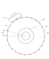
次にクランク角の検出構成について説明する。図2に示すように、クランクシャフト3には、円盤状のロータ30が固定されている。これにより、ロータ30は、クランクシャフト3と一体回転可能に構成される。ロータ30の外周面には、径方向外側に突出した複数の突起部31(リラクタ)が形成されている。突起部31は、ロータ30の周方向で所定幅を有している。突起部31は、クランクシャフト3の外周に等角度間隔で配置されており、図2では15度間隔で配置されている。なお、図2では、連続する2箇所において突起部31が形成されない欠損部32が設けられており、突起部31は合計して22個配置されている。
Next, the configuration for detecting the crank angle will be explained. As shown in FIG. 2, a disk-shaped
ロータ30の外周側には、クランク角センサ14が配置されている。クランク角センサ14は、GMR素子やMR素子等によって構成される電磁式のセンサであり、検出部が突起部31に対向するように配置される。すなわち、突起部31は、クランク角を検出するための被検出部を構成する。
A
クランク角センサ14は、クランクシャフト3の回転に伴って検出部に対向する突起部31が当該検出部を通過するときに突起部31との接近を検出する。このとき、クランク角センサ14は、信号としてクランクパルスを発生する。当該クランクパルスは、ECM4に出力される。ECM4は、クランクパルスの間隔や所定時間内に取得したクランクパルスの数からクランク角、すなわちクランクシャフト3の回転数(回転速度)を算出することが可能である。なお、本実施の形態では、突起部31が22個設けられているため、ECM4は、22+1=23個目のクランクパルスを取得したことでクランクシャフト3が1回転したことを認識することが可能である。
The
ところで、自動二輪車のエンジン始動装置においては、より安全にエンジンを始動できるように、クラッチレバーやブレーキレバーを握った状態でスタータスイッチを操作することが一般的である。一方で、エンジン始動時の操作を簡素化するため、所定の条件を満たせば上記のレバー等を握らなくてもスタータスイッチを押している間だけスタータモータに通電してエンジンを始動可能とした装置も存在する。 By the way, in an engine starting device for a motorcycle, in order to start the engine more safely, it is common to operate a starter switch while holding a clutch lever or a brake lever. On the other hand, in order to simplify the operation when starting the engine, there is also a device that allows the engine to be started by energizing the starter motor only while the starter switch is pressed, without having to hold the lever mentioned above, if certain conditions are met. exist.
更に始動時の操作を簡素化する目的で、車両に装備された各種センサからの信号を用いてスタータモータの作動時間を制御し、スタータスイッチをワンプッシュするだけで所定時間スタータモータを作動させてエンジンを始動させる装置も存在する。始動時の操作の簡素化は、ユーザメリットが大きいため、今後も開発が検討される分野である。 Furthermore, in order to simplify the operation during starting, the operating time of the starter motor is controlled using signals from various sensors installed in the vehicle, and the starter motor is operated for a predetermined period of time with just one push of the starter switch. There are also devices that start the engine. Simplifying operations at startup has great benefits for users, so this is an area that will continue to be considered for further development.
しかしながら、コンパクトさが求められる自動二輪車の分野にあっては、限られた数のセンサの信号から車両状態を推定する必要があるため、ECMで得た情報が必ずしも車両状態を適切に示すとは限らない場合が考えられる。 However, in the field of motorcycles where compactness is required, it is necessary to estimate the vehicle condition from the signals of a limited number of sensors, so the information obtained by ECM does not necessarily indicate the vehicle condition appropriately. There may be cases where this is not the case.
例えば、エンジン停止時には変速段がニュートラル位置であったにもかかわらず、スタータモータの駆動後に何らかの理由でギヤが噛み合ってしまい、正常にエンジン始動できない場合が想定される。すなわち、エンジン始動前の車両状態を各種センサから読み取るだけでは不十分であり、操作の簡素化と適切な始動性とを両立させることは困難であった。 For example, even though the gear position is in the neutral position when the engine is stopped, the gears may become engaged for some reason after the starter motor is driven, and the engine cannot be started normally. That is, it is not sufficient to simply read the vehicle state from various sensors before starting the engine, and it has been difficult to achieve both simplification of operation and appropriate startability.
ここで、図3を参照してクランキング後のクランク角の経時変化について説明する。図3は、時間に対するクランク角を示すグラフの一例である。より具体的に図3の横軸はクランキング開始後の経過時間を示し、縦軸はクランクパルス累積数を示している。 Here, the change over time of the crank angle after cranking will be explained with reference to FIG. FIG. 3 is an example of a graph showing crank angle versus time. More specifically, the horizontal axis in FIG. 3 shows the elapsed time after the start of cranking, and the vertical axis shows the cumulative number of crank pulses.
図3の実線に示すように、ニュートラル時にスタータモータが作動してクランキングされると、クランクシャフトは時間経過に伴って適切に回転して所定角度回転したところで初爆を迎え、適切なエンジン始動に至る。 As shown by the solid line in Figure 3, when the starter motor operates and cranks when in neutral, the crankshaft rotates appropriately over time and reaches the first explosion when it has rotated by a predetermined angle, allowing the engine to start properly. leading to.
一方で図3の破線に示すように、ギヤ噛みが発生した状態でクランキングされると、噛み合ったギヤの抵抗によりクランクシャフトが十分に回転せず、エンジンは初爆を迎えることなく停止してしまう。このように、ニュートラル時とギヤ噛み時では、クランキング開始後のクランク角の変化に大きな差が生じることが見て取れる。 On the other hand, as shown by the broken line in Figure 3, if the engine is cranked with gear engagement, the crankshaft will not rotate sufficiently due to the resistance of the engaged gears, and the engine will stop without reaching its first explosion. Put it away. In this way, it can be seen that there is a large difference in the change in crank angle after the start of cranking between the neutral state and the gear engagement state.
そこで、本件発明者等は、ニュートラル状態とギヤ噛みあい状態とではスタータモータを駆動し始めたときのクランクパルス間の時間立ち上がりで明確な差がある点に着目し、本発明に想到した。本発明の骨子は、ECM4において、この差をクランキング開始後に検出して、ギヤ噛み合い状態と判定した場合に即座にスタータモータの作動を停止して車両(ギヤ)の振動を防止することである。 Therefore, the inventors of the present invention focused on the fact that there is a clear difference in the time rise between crank pulses when starting to drive the starter motor between the neutral state and the gear mesh state, and came up with the present invention. The gist of the present invention is that the ECM4 detects this difference after starting cranking, and when it is determined that the gears are engaged, immediately stops the operation of the starter motor to prevent vehicle (gear) vibration. .
具体的に本実施の形態では、ECM4は、スタータモータ2の作動時において、所定時間内でのクランクシャフト3の回転角度が予め設定された角度よりも小さい場合、又は、クランクシャフト3が所定角度回転するまでの時間が予め設定された時間よりも長い場合、スタータモータの作動を停止させることを特徴とする。すなわち、ECM4は、スタータモータ2が作動している最中にクランク角センサ14によって検出する回転速度情報を用いてエンジンの負荷状態を判断することができる。より具体的には、「所定時間内でのクランクシャフト3の回転角度が予め設定された角度よりも小さい場合」、又は、「クランクシャフト3が所定角度回転するまでの時間が予め設定された時間よりも長い場合」には、ギヤの噛み合いに起因するクランクシャフト3への負荷が発生したと判断することができる。
Specifically, in the present embodiment, when the starter motor 2 is operated, the ECM 4 detects that when the rotation angle of the crankshaft 3 within a predetermined time is smaller than a preset angle, or when the crankshaft 3 rotates at a predetermined angle. If the time until rotation is longer than a preset time, the operation of the starter motor is stopped. That is, the ECM 4 can determine the load state of the engine using rotational speed information detected by the
この構成によれば、たとえ車両に装備された各種センサが誤判定をしてスタータモータが作動開始した後でもクランキング速度から負荷、すなわちギヤ噛み合い状態を検出し、負荷が大きいと判断した場合はスタータモータ2の作動を即座に停止することができる。これにより、エンジンで通常用いられるクランク角センサ14を用いたシンプルな構成でクランクシャフト3にかかる負荷の判定、及びスタータモータ2の作動の適否判定を行うことができ、整備性を保ちつつ車両の快適性が向上する。以上より、エンジンの始動操作の簡素化と適切な始動性との両立を図り、ギヤの接触による振動を抑えて快適なエンジン始動性を実現することが可能である。
According to this configuration, even after various sensors installed in the vehicle make a false determination and the starter motor starts operating, the load, that is, the gear engagement state, is detected from the cranking speed, and if it is determined that the load is large, the The operation of the starter motor 2 can be stopped immediately. As a result, it is possible to determine the load applied to the crankshaft 3 and the suitability of operation of the starter motor 2 with a simple configuration using the
また、ECM4は、スタータモータ2の作動中に任意の所定時間範囲内にクランクパルスが所定回数検出されなかった場合、又は、スタータモータ2の作動中に任意のタイミングからクランクパルスを所定回数検出するまでに要した時間が閾値よりも大きかった場合、スタータモータの作動を停止させる。また、ECM4は、スタータモータ2の作動中にクランクパルスの検出間隔が所定時間よりも長い場合、スタータモータの作動を停止させる。この構成によれば、既存のクランク角センサ14の信号をそのまま用いることで、新たなセンサを追加することなくクランクシャフト3の負荷判定を実施することが可能である。
In addition, the ECM 4 detects crank pulses a predetermined number of times from an arbitrary timing during operation of the starter motor 2, or when a crank pulse is not detected a predetermined number of times within an arbitrary predetermined time range while the starter motor 2 is operating. If the time required for this is greater than a threshold value, the operation of the starter motor is stopped. Furthermore, when the crank pulse detection interval is longer than a predetermined time while the starter motor 2 is in operation, the ECM 4 stops the operation of the starter motor. According to this configuration, by using the signal of the existing
また、上記したクランクパルスの所定回数は、クランクシャフト3の1回転分以上とすることが好ましい。クランクシャフト3の負荷判定を実施する場合は必ずクランクシャフト3を1回転させることでギヤ間のバックラッシュによる無負荷状態が解消され、より正確にクランクシャフト3の負荷判定を実施することが可能である。また、負荷判定開始時のクランクシャフト3の位置が毎回違う場合であっても、必ず判定時間内に欠損部32を含むことになる。これにより、判定毎のバラツキを抑えることができ、既存のクランク角センサ14を用いた場合であっても安定した負荷判定を実施することが可能になる。
Further, it is preferable that the predetermined number of crank pulses described above be equal to or more than one revolution of the crankshaft 3. When performing a load determination on the crankshaft 3, be sure to rotate the crankshaft 3 once to eliminate the no-load state due to backlash between gears, and it is possible to perform a more accurate load determination on the crankshaft 3. be. Furthermore, even if the position of the crankshaft 3 at the start of the load determination is different each time, the missing
また、ECM4は、スタータスイッチの押下操作に応じてクランクシャフト負荷判定を実施するか否かを判断し、押下操作が瞬間的である場合(押下後にすぐスタータスイッチ17を離す場合)にクランクシャフト負荷判定を実施し、押下操作が継続的である場合にスタータモータを作動させ続ける。この構成によれば、スタータスイッチの押下操作が瞬間的であっても、クランクシャフト負荷判定の結果、クランクシャフト3に負荷が生じていなければスタータモータ2が作動してクランキングされる。これにより、簡易な操作でエンジン始動が可能である。また、スタータスイッチ17の押下操作が継続的であれば、スタータモータ2を作動させ続けることで、乗員の意向に沿ったエンジン始動が可能となる。 In addition, the ECM 4 determines whether or not to perform crankshaft load determination in response to the press operation of the starter switch, and if the press operation is instantaneous (when the starter switch 17 is released immediately after being pressed), the crankshaft load A determination is made, and if the pressing operation continues, the starter motor continues to operate. According to this configuration, even if the starter switch is pressed momentarily, if the result of the crankshaft load determination is that there is no load on the crankshaft 3, the starter motor 2 will be operated and cranking will be performed. This makes it possible to start the engine with a simple operation. Further, if the starter switch 17 is continuously depressed, the starter motor 2 continues to operate, thereby making it possible to start the engine according to the passenger's intention.
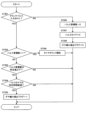
次に、図4及び図5を参照して、本実施の形態に係る制御フローについて説明する。図4は、本実施の形態に係るエンジン始動制御の一例を示すフロー図である。図5は、本実施の形態に係るギヤ噛み判定制御(クランクシャフト負荷判定)の一例を示すフロー図である。なお、以下に示すフローでは、特に明示がない限り、動作(算出(演算)や判定等)の主体はECMとする。なお、図4及び図5に示す制御フローでは、「スタート」から「エンド」までの処理が所定時間の間隔で繰り返して実施されるものとする。 Next, the control flow according to this embodiment will be described with reference to FIGS. 4 and 5. FIG. 4 is a flow diagram showing an example of engine start control according to the present embodiment. FIG. 5 is a flowchart showing an example of gear engagement determination control (crankshaft load determination) according to the present embodiment. In addition, in the flow shown below, unless otherwise specified, the main body of the operation (calculation (operation), determination, etc.) is assumed to be the ECM. In the control flows shown in FIGS. 4 and 5, it is assumed that the process from "start" to "end" is repeated at predetermined time intervals.
先ずスタータリレー20の通電制御フローについて説明する。図4に示すように、制御が開始されると、ステップST101において、ECM4は、変速段がニュートラルであるか否かを判定する。ECM4は、例えばギヤポジションセンサ10やニュートラルスイッチ12の出力に基づいて現在の変速段がニュートラルであるか否かを判定することが可能である。変速段がニュートラルである場合(ステップST101:YES)、ステップST102の処理に進む。変速段がニュートラルでない場合(ステップST101:NO)、ステップST105の処理に進む。
First, the energization control flow of the
ステップST102において、ECM4は、エンジン回転数(クランクシャフト3の回転数)が所定値A以下であるか否かを判定する。ECM4は、例えばクランク角センサ14から所定時間内に得られるクランクパルス数や、所定クランクパルス数を取得するまでの時間に基づいてエンジン回転数を算出する。エンジン回転数が所定値A以下である場合(ステップST102:YES)、ステップST103の処理に進む。エンジン回転数が所定値A以下でない場合(ステップST102:NO)、ステップST106の処理に進む。
In step ST102, the ECM 4 determines whether the engine rotation speed (the rotation speed of the crankshaft 3) is equal to or lower than a predetermined value A. The ECM 4 calculates the engine rotation speed based on, for example, the number of crank pulses obtained from the
ステップST103において、ECM4は、スタータスイッチ17がオンされたか否かを判定する。ECM4は、例えばスタータスイッチ17からの信号の有無に基づいてオンされたか否かを判定することが可能である。スタータスイッチ17がオンされた場合(ステップST103:YES)、ステップST104の処理に進む。スタータスイッチ17がオンされない場合(ステップST103:NO)、ステップST107の処理に進む。 In step ST103, the ECM 4 determines whether the starter switch 17 is turned on. The ECM 4 can determine whether it is turned on based on the presence or absence of a signal from the starter switch 17, for example. If the starter switch 17 is turned on (step ST103: YES), the process proceeds to step ST104. If the starter switch 17 is not turned on (step ST103: NO), the process proceeds to step ST107.
ステップST104において、ECM4は、スタータリレー20に通電させ、制御を終了する。スタータリレー20が通電されることで、スタータモータ2が作動される。
In step ST104, the ECM 4 energizes the
ステップST105において、ECM4は、クラッチスイッチ11がオンされたか否か、すなわち乗員がクラッチレバーを握っているか否かを判定する。ECM4は、例えばクラッチスイッチ11からの信号の有無に基づいてオンされたか否かを判定することが可能である。クラッチスイッチ11がオンされた場合(ステップST105:YES)、ステップST102の処理に進む。クラッチスイッチ11がオンされない場合(ステップST105:NO)、ステップST109の処理に進む。 In step ST105, the ECM 4 determines whether the clutch switch 11 is turned on, that is, whether the occupant is gripping the clutch lever. The ECM 4 can determine whether it is turned on based on the presence or absence of a signal from the clutch switch 11, for example. When the clutch switch 11 is turned on (step ST105: YES), the process proceeds to step ST102. If the clutch switch 11 is not turned on (step ST105: NO), the process proceeds to step ST109.
ステップST106において、ECM4は、エンジン回転数が所定値B以上であるか否かを判定する。所定値Bは、例えば所定値Aよりも大きい値とする。エンジン回転数が所定値B以上である場合(ステップST106:YES)、ステップST109の処理に進む。エンジン回転数が所定値B以上でない(ステップST106:NO)、ステップST103の処理に進む。 In step ST106, the ECM 4 determines whether the engine speed is equal to or higher than a predetermined value B. The predetermined value B is, for example, a value larger than the predetermined value A. If the engine speed is equal to or higher than the predetermined value B (step ST106: YES), the process proceeds to step ST109. If the engine speed is not equal to or higher than the predetermined value B (step ST106: NO), the process proceeds to step ST103.
ステップST107において、ECM4は、スタータスイッチ17のオフ状態が所定時間以上経過したか否かを判定する。スタータスイッチ17のオフ状態が所定時間以上経過した場合(ステップST107:YES)、ステップST109の処理に進む。スタータスイッチ17のオフ状態が所定時間以上経過していない場合(ステップST107:NO)、ステップST108の処理に進む。 In step ST107, the ECM 4 determines whether the starter switch 17 has been in the OFF state for a predetermined period of time or more. If the starter switch 17 remains off for a predetermined period of time or more (step ST107: YES), the process proceeds to step ST109. If the starter switch 17 remains off for a predetermined period of time or more (step ST107: NO), the process proceeds to step ST108.
ステップST108において、ECM4は、ギヤ噛み検出フラグがあるか否かを判定する。ギヤ噛み検出フラグについては後述する。ギヤ噛み検出フラグがある場合(ステップST108:YES)、ステップST109の処理に進む。ギヤ噛み検出フラグがない場合(ステップST108:NO)、ステップST104の処理に進む。 In step ST108, the ECM 4 determines whether or not there is a gear engagement detection flag. The gear engagement detection flag will be described later. If there is a gear engagement detection flag (step ST108: YES), the process proceeds to step ST109. If there is no gear engagement detection flag (step ST108: NO), the process proceeds to step ST104.
ステップST109において、ECM4は、スタータリレー20への通電を停止させ、制御を終了する。スタータリレー20への通電が停止されることで、スタータモータ2の作動が停止される。
In step ST109, the ECM 4 stops energizing the
次にギヤ噛み検出フロー(クランクシャフト負荷判定フロー)について説明する。なお、ギヤ噛み検出フローとは、ギヤが噛み合ってクランクシャフト3に負荷が発生しているか否かを判定するフローである。また、制御開始時、ギヤ噛み検出フラグ=0(すなわちギヤ噛みが発生していない状態)に設定されているものとする。 Next, the gear engagement detection flow (crankshaft load determination flow) will be explained. Note that the gear engagement detection flow is a flow for determining whether gears are engaged and a load is generated on the crankshaft 3. Furthermore, it is assumed that the gear engagement detection flag is set to 0 (that is, a state in which no gear engagement occurs) at the start of the control.
図5に示すように、制御が開始されると、ステップST201において、ECM4は、クランクパルスが入力されたか否かを判定する。ECM4は、例えばクランク角センサ14からの信号に基づいてクランクパルスが入力されたか否かを判定する。クランクパルスが入力された場合(ステップST201:YES)、ステップST202の処理に進む。クランクパルスが入力されない、すなわちクランクシャフト3が回転せずに止まっている場合(ステップST201:NO)、ステップST206の処理に進む。
As shown in FIG. 5, when control is started, in step ST201, the ECM 4 determines whether a crank pulse is input. The ECM 4 determines whether or not a crank pulse is input based on a signal from the
ステップST202において、ECM4は、クランクパルスの累積数が1である、すなわちクランクシャフト3が回り始めたか否かを判定する。クランクパルスの累積数が1である場合(ステップST202:YES)、ステップST209の処理に進む。クランクパルスの累積数が1でない場合(ステップST202:NO)、ステップST203の処理に進む。 In step ST202, the ECM 4 determines whether the cumulative number of crank pulses is 1, that is, whether the crankshaft 3 has started rotating. If the cumulative number of crank pulses is 1 (step ST202: YES), the process proceeds to step ST209. If the cumulative number of crank pulses is not 1 (step ST202: NO), the process proceeds to step ST203.
ステップST203において、ECM4は、クランクパルスの累積数が所定値以下であるか否かを判定する。当該所定値は、例えばギヤ噛み検出可能なクランクパルス数に設定される。クランクパルスの累積数が所定値以下である場合(ステップST203:YES)、ステップST204の処理に進む。クランクパルスの累積数が所定値以下でない場合(ステップST203:NO)、ギヤ噛み検出フラグは前回の状態を維持したまま、制御を終了する。 In step ST203, the ECM 4 determines whether the cumulative number of crank pulses is less than or equal to a predetermined value. The predetermined value is set to, for example, the number of crank pulses that can detect gear engagement. If the cumulative number of crank pulses is less than or equal to the predetermined value (step ST203: YES), the process proceeds to step ST204. If the cumulative number of crank pulses is not equal to or less than the predetermined value (step ST203: NO), the control is ended while the gear engagement detection flag maintains the previous state.
ステップST204において、ECM4は、パルスタイマが所定時間経過したか否かを判定する。当該所定時間は、例えばギヤ噛み検出可能な経過時間に設定される。パルスタイマが所定時間経過した場合(ステップST204:YES)、ステップST205の処理に進む。パルスタイマが所定時間経過していない場合(ステップST204:NO)、ギヤ噛み検出フラグは前回の状態を維持したまま、制御を終了する。 In step ST204, the ECM 4 determines whether the pulse timer has elapsed for a predetermined period of time. The predetermined time is set, for example, to an elapsed time that allows gear engagement to be detected. If the pulse timer has elapsed for a predetermined period of time (step ST204: YES), the process proceeds to step ST205. If the predetermined time has not elapsed on the pulse timer (step ST204: NO), the control is ended while the gear engagement detection flag maintains the previous state.
ステップST205において、ECM4は、ギヤ噛み検出フラグ=1に設定して制御を終了する。 In step ST205, the ECM 4 sets the gear engagement detection flag=1 and ends the control.
ステップST206において、ECM4は、パルス累積数=0に設定する。そして、ステップST207の処理に進む。 In step ST206, the ECM 4 sets the cumulative number of pulses to 0. Then, the process proceeds to step ST207.
ステップST207において、ECM4は、パルスタイマ=0に設定する。そして、ステップST208の処理に進む。 In step ST207, the ECM 4 sets the pulse timer=0. Then, the process proceeds to step ST208.
ステップST208において、ECM4は、ギヤ噛み検出フラグ=0に設定する。そして、制御を終了する。 In step ST208, the ECM 4 sets the gear engagement detection flag=0. Then, control ends.
ステップST209において、ECM4は、パルスタイマのカウントを開始する。そして、制御を終了する。 In step ST209, the ECM 4 starts counting the pulse timer. Then, control ends.
以上説明したように、本実施の形態では、車両内の既存のセンサ等の出力から車両のギヤ噛み検出(クランクシャフト負荷判定)を実施し、ギヤ噛み(負荷)を検出した場合に、スタータモータ2への通電が停止される。これにより、負荷状態でエンジンが始動することを防止し、新たなセンサを追加することなく、ギヤの接触による振動を抑えて快適なエンジン始動性を実現できる。 As explained above, in this embodiment, gear engagement detection (crankshaft load determination) of the vehicle is performed from the output of existing sensors in the vehicle, and when gear engagement (load) is detected, the starter motor The power supply to 2 is stopped. This prevents the engine from starting under load, suppresses vibrations caused by gear contact, and provides comfortable engine startability without the need to add new sensors.
なお、上記実施の形態において、ECM4が、スタータモータ2の作動中、任意の所定時間範囲内にクランクパルスが所定回数検出されなかった場合、すなわちクランクシャフト3の回転速度が所定回転速度よりも小さい場合、クランクシャフト3にギヤから負荷がかかっている状態と判定してスタータモータ2の作動を停止する構成としたがこの構成に限定されない。例えば、ECM4は、スタータモータ2の作動中、任意のタイミングからクランクパルスを所定回数検出するまでにかかった時間が閾値よりも大きかった場合、もしくはスタータモータ2の作動中、クランクパルスの検出間隔が所定時間よりも長い場合、スタータモータ2の作動を停止してもよい。 In the above embodiment, when the ECM 4 detects that a crank pulse is not detected a predetermined number of times within an arbitrary predetermined time range while the starter motor 2 is operating, that is, the rotation speed of the crankshaft 3 is smaller than the predetermined rotation speed. In this case, it is determined that a load is being applied to the crankshaft 3 from the gear, and the operation of the starter motor 2 is stopped. However, the present invention is not limited to this configuration. For example, during operation of the starter motor 2, the ECM 4 determines whether the time taken from an arbitrary timing to detect the crank pulse a predetermined number of times is greater than a threshold value, or when the interval between detection of crank pulses during the operation of the starter motor 2 is If the time is longer than the predetermined time, the operation of the starter motor 2 may be stopped.
また、上記実施の形態において、上記の所定時間及び所定回数は、エンジン無負荷状態において、通常のエンジン始動を行った場合のクランクパルスの検出回数を予め取得し、これに基づいて設定することが好ましい。 Furthermore, in the embodiment described above, the predetermined time and the predetermined number of times may be set based on the number of times the crank pulse is detected when the engine is started normally in a no-load state of the engine. preferable.
また、上記実施の形態において、所定回数は例えばクランクシャフト3の1回転分(23回)であることが好ましい。しかしながら、これに限定されず、所定回数は適宜変更が可能である。例えば、変速ギヤ駆動伝達部品のバックラッシュが取り除かれるのに十分な回転角度を確保できれば、所定回数は、1回転分未満であってもよい。 Further, in the embodiment described above, it is preferable that the predetermined number of times is, for example, one rotation of the crankshaft 3 (23 times). However, it is not limited to this, and the predetermined number of times can be changed as appropriate. For example, the predetermined number of times may be less than one rotation as long as a rotation angle sufficient to eliminate backlash of the speed change gear drive transmission component can be secured.
また、上記実施の形態において、突起部31の数が22個で欠損部32が2個設けられる場合について説明したが、この構成に限定されない。突起部31及び欠損部32の個数は適宜変更が可能である。また、欠損部32のかわりに突起部31よりも長い別の突起部を設けてもよい。
Further, in the above embodiment, a case has been described in which the number of
次に、実施の第2形態について添付図面を参照して詳細に説明する。なお、前述の実施の形態と同様、本発明が適用される車両として二輪車(鞍乗型車両)を例にして説明するが、適用対象はこれに限定されることなく変更可能である。例えば四輪車等、他のタイプの車両にも適用可能である。また、前述の実施の形態と重複する箇所は割愛する。なお、上記実施の形態では、クランクパルスからギヤ噛みを検出する場合について説明したが、第2形態では、車輪(前輪及び後輪)の回転角度(回転速度)からギヤ噛みを検出する点で相違する。 Next, a second embodiment will be described in detail with reference to the accompanying drawings. Note that, similar to the above-described embodiments, a two-wheeled vehicle (straddle type vehicle) will be described as an example of a vehicle to which the present invention is applied, but the applicable target is not limited to this and can be changed. It is also applicable to other types of vehicles, such as four-wheeled vehicles. Further, parts that overlap with the above-described embodiments will be omitted. In the above embodiment, the case where gear engagement is detected from the crank pulse has been described, but the second embodiment is different in that gear engagement is detected from the rotation angle (rotation speed) of the wheels (front wheel and rear wheel). do.
図1、図4、及び図6から図8を参照して、本実施の第2形態に係るエンジン始動制御システムについて説明する。図1は、前述の実施の形態と同様、本実施の第2形態に係るエンジン始動制御システムのブロック図であり、エンジン始動制御システム1は、ECM4、前輪速度センサ15、後輪速度センサ16、及びスタータスイッチ17を備えている。
An engine start control system according to a second embodiment of the present invention will be described with reference to FIGS. 1, 4, and 6 to 8. FIG. 1 is a block diagram of an engine start control system according to the second embodiment, similar to the above embodiment, and the engine start control system 1 includes an ECM 4, a front
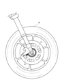
図6は、本実施の第2形態に係る車輪速度センサ及び車輪速度センサロータの一例を示す構成図である。図7は、図6の部分拡大図である。図6及び図7に示すように、前輪速度センサ15は、前輪40を回転可能に支持する支持軸の付近に配置され、車体の懸架部品側に取り付けられる。そして前輪40に回転一体に取り付けられる被検出部(前輪速度センサロータ41)を検出してホイール回転数に比例したパルス信号を発生し、その検出値をECM4に出力する。これにより、前輪40の速度を検出することができる。
FIG. 6 is a configuration diagram showing an example of a wheel speed sensor and a wheel speed sensor rotor according to the second embodiment. FIG. 7 is a partially enlarged view of FIG. 6. As shown in FIGS. 6 and 7, the front
特に図示はしないが、後輪速度センサ16も、前輪速度センサ15と同様に、後輪を回転可能に支持する支持軸の付近に配置され、車体の懸架部品側に取り付けられる。そして後輪のホイールハブに回転一体に取り付けられる被検出部(後輪速度センサロータ(不図示))を検出してホイール回転数に比例したパルス信号を発生し、その検出値をECM4に出力する。これにより、後輪の速度を検出することができる。
Although not particularly illustrated, the rear
次に車輪速度の検出構成について説明する。図6及び図7に示すように、前輪40のホイールハブに円盤状の前輪速度センサロータ41が固定されている。これにより、前輪速度センサロータ41は、前輪と一体回転可能に構成される。前輪速度センサロータ41の板状面の外周部分には、周方向に等角度間隔に並んで一周するようにスリット42が複数形成される。
Next, the configuration for detecting wheel speed will be explained. As shown in FIGS. 6 and 7, a disk-shaped front wheel
前輪速度センサロータ41の板状面に向い合う様に、前輪速度センサ15が配置されている。前輪速度センサ15は、ホール素子によって構成される電磁式のセンサであり、検出部がスリット42に対向するように配置される。すなわち、スリット42とその中間部43によって、車輪速度を検出するための被検出部を構成する。
Front
前輪速度センサ15は、前輪40の回転に伴って検出部に対向するスリット42と中間部43とが当該検出部を交互に通過するときに接近するのを検出する。このとき、前輪速度センサ15は、パルス信号を発生する。当該パルス信号は、ECM4に出力される。ECM4は、パルス信号の間隔や所定時間内に取得したパルス信号の数から、前輪の回転速度を算出することが可能である。なお、本実施の第2形態では、スリット42及び中間部43が50個ずつ設けられている。この個数は適宜変更が可能である。
The front
ところで、エンジン停止時には変速段がニュートラル位置であったにもかかわらず、スタータモータ2の駆動後に何らかの理由でギヤが噛み合ってしまった場合、クランキングによってクランクシャフトからクラッチ、変速装置等を経て車輪へ回転が伝わる場合も想定される。 By the way, if the gears are in the neutral position when the engine is stopped, but for some reason the gears are engaged after the starter motor 2 is driven, the crankshaft passes through the clutch, transmission, etc., and then goes to the wheels. It is also assumed that rotation may be transmitted.
ここで本件発明者等は、ギヤ噛み合い状態における車輪への回転力の伝達に着目し、本発明に想到した。本発明の骨子は、ECM4において、この回転力の伝達(車輪の時間当たりの回転角度)を瞬時に検出して、ギヤ噛み合い状態と判定した場合に即座にスタータモータ2の作動を停止することで、車両の振動を抑えて乗員の不快感を低減することである。 Here, the inventors of the present invention focused on the transmission of rotational force to wheels in a gear meshing state, and came up with the present invention. The gist of the present invention is that the ECM 4 instantly detects the transmission of this rotational force (wheel rotation angle per hour) and immediately stops the operation of the starter motor 2 when it is determined that the gears are engaged. , to suppress vehicle vibrations and reduce passenger discomfort.
具体的に本実施の第2形態では、ECM4は、スタータモータ2の作動時において、所定時間内での前輪40の回転角度が予め設定された角度よりも大きい場合、スタータモータ2の作動を停止させることを特徴とする。すなわち、ECM4は、スタータモータ2が作動している最中に前輪速度センサ15又は後輪速度センサ16によって検出する回転速度情報を用いてエンジンの負荷状態を判断することができる。より具体的には、「前輪40の微回転を検出した場合」には、ギヤの噛み合いに起因する車輪への回転力の伝達とそれに伴う車両の振動が発生したと判断することができる。本実施の第2形態では、「スタータモータ2に通電した時点ではパルス信号間時間が所定時間よりも長く、その後に所定値以下のパルス信号間時間を検出した場合」に車両の振動が発生したと判断する。これは、車輪の回転のない状態では次のパルス信号の取得がないためにパルス信号間時間は十分長くなるが、車輪が微回転すると次のパルス信号が取得されてより短いパルス信号間時間が検出されるため、このパルス間時間の長短によって車輪の回転が判断可能なことによる。また、車輪回転判定を前輪と後輪の両方で行っており、何れか一方での判定に比べて確実な判定が可能になる。
Specifically, in the second embodiment, the ECM 4 stops the operation of the starter motor 2 when the rotation angle of the
この構成によれば、たとえ車両に装備された各種センサが誤判定をしてスタータモータ2が作動開始した後でも車輪回転速度からギヤ噛み合い状態を検出し、スタータモータ2の作動を即座に停止することができる。これにより、鞍乗型車両で普及している前輪速度センサ15または後輪速度センサ16を用いたシンプルな構成で車輪への回転力伝達有無の判定、及びスタータモータ2の作動の適否判定を行うことができ、整備性を保ちつつ車両の快適性が向上する。以上より、エンジンの始動操作の簡素化と適切な始動性との両立を図り、ギヤの接触による車両の振動を抑えて快適なエンジン始動性を実現することが可能である。
According to this configuration, even if various sensors installed in the vehicle make a false determination and the starter motor 2 starts operating, the gear engagement state is detected from the wheel rotation speed and the operation of the starter motor 2 is immediately stopped. be able to. As a result, it is possible to determine whether or not rotational force is transmitted to the wheels, and to determine whether or not the operation of the starter motor 2 is appropriate, with a simple configuration using the front
また、ECM4は、「スタータモータ2の作動開始時点において、車輪が既に回転している場合」には、スタータモータ2の作動を続行させることを特徴とする。すなわち、スタータモータ2を作動させる前から乗員が意図的に車輪を回転させている場合では、例外的に車輪が回転していてもスタータモータ2の作動を継続する。これにより、例えばニュートラルにして下り坂を惰性で降りながらスタータモータ2が使用でき、車両の利便性が向上する。本実施の第2形態では、「スタータモータ2の作動開始時点において、既に所定値以下のパルス信号間時間を検出している場合」に、スタータモータ2の作動を続行させる。 Furthermore, the ECM 4 is characterized by causing the starter motor 2 to continue operating "if the wheels are already rotating when the starter motor 2 starts operating." That is, if the occupant is intentionally rotating the wheels before starting the starter motor 2, the starter motor 2 continues to operate even if the wheels are rotating. As a result, the starter motor 2 can be used, for example, while going downhill by inertia in neutral, improving the convenience of the vehicle. In the second embodiment, the operation of the starter motor 2 is continued when "the time between pulse signals that is equal to or less than a predetermined value has already been detected at the time when the operation of the starter motor 2 is started".
次に、図4及び図8を参照して、本実施の第2形態に係る制御フローについて説明する。図4は、本実施の第2形態に係るエンジン始動制御の一例を示すフロー図であり、先述の実施の形態と同様であるため説明は割愛する。図8は、本実施の第2形態に係る車輪回転判定の一例を示すフロー図である。なお、以下に示すフローでは、特に明示がない限り、動作(算出(演算)や判定等)の主体はECM4とする。なお、図4及び図8に示す制御フローでは、「スタート」から「エンド」までの処理が所定時間の間隔で繰り返して実施されるものとする。 Next, the control flow according to the second embodiment will be described with reference to FIGS. 4 and 8. FIG. 4 is a flowchart showing an example of engine start control according to the second embodiment, and since it is similar to the embodiment described above, a description thereof will be omitted. FIG. 8 is a flow diagram showing an example of wheel rotation determination according to the second embodiment. In the flow shown below, unless otherwise specified, the ECM 4 is responsible for the operations (calculations, determinations, etc.). In the control flows shown in FIGS. 4 and 8, it is assumed that the process from "start" to "end" is repeated at predetermined time intervals.
図8で、車輪回転判定フローについて説明する。なお、車輪回転判定フローとは、ギヤが噛み合って車輪の微回転が発生しているか否かを判定するフローである。また、制御開始時、ギヤ噛み検出フラグ=0(すなわち車輪は回転していない状態)に設定されているものとする。 Referring to FIG. 8, a wheel rotation determination flow will be described. Note that the wheel rotation determination flow is a flow for determining whether the gears are engaged and slight rotation of the wheels is occurring. Furthermore, it is assumed that the gear engagement detection flag is set to 0 (that is, the wheels are not rotating) at the start of the control.
制御が開始されると、ステップST301において、ECM4は、クランクパルスが入力されたか否かを判定する。ECM4は、例えばクランク角センサ14からの信号に基づいてクランクパルスが入力されたか否かを判定する。クランクパルスが入力された場合(ステップST301:YES)、ステップST302の処理に進む。クランクパルスが入力されない、すなわちクランクシャフト3が回転せずに止まっている場合(ステップST301:NO)、ステップST308の処理に進む。
When control is started, in step ST301, the ECM 4 determines whether a crank pulse is input. The ECM 4 determines whether or not a crank pulse is input based on a signal from the
ステップST302において、ECM4は、クランクパルスの累積数が所定値以下であるか否かを判定する。当該所定値は、例えばギヤ噛み検出可能なクランクパルス数に設定されてもよい。クランクパルスの累積数が所定値以下である場合(ステップST302:YES)、ステップST303の処理に進む。クランクパルスの累積数が所定値以下でない場合(ステップST302:NO)、ギヤ噛み検出フラグは前回の状態を維持したまま、制御を終了する。 In step ST302, the ECM 4 determines whether the cumulative number of crank pulses is less than or equal to a predetermined value. The predetermined value may be set to, for example, the number of crank pulses that can detect gear engagement. If the cumulative number of crank pulses is less than or equal to the predetermined value (step ST302: YES), the process proceeds to step ST303. If the cumulative number of crank pulses is not equal to or less than the predetermined value (step ST302: NO), the control is ended while the gear engagement detection flag maintains the previous state.
ステップST303において、ECM4は、前輪について前回のパルス信号間の間隔が0、すなわち前輪が無回転であったか否かを判定する。パルス信号間の間隔が0、すなわち前輪が無回転の場合(ステップST303:YES)、ステップST304の処理に進む。パルス信号間の間隔が0ではない、すなわち直前で前輪の回転が有った場合(ステップST303NO)、ギヤ噛み検出フラグは前回の状態を維持したまま、制御を終了する。 In step ST303, the ECM 4 determines whether or not the interval between the previous pulse signals for the front wheels is 0, that is, the front wheels are not rotating. If the interval between pulse signals is 0, that is, the front wheels are not rotating (step ST303: YES), the process proceeds to step ST304. If the interval between the pulse signals is not 0, that is, if the front wheels have rotated immediately before (step ST303 NO), the control is ended while the gear engagement detection flag maintains the previous state.
ステップST304において、ECM4は、前輪について現在のパルス信号間の間隔が0よりも大きい、すなわち前輪が回り始めたか否かを判定する。パルス信号間の間隔が0よりも大きい、すなわち前輪が回り始めた場合(ステップST304:YES)、ステップST305の処理に進む。パルス信号間の間隔が0、すなわち現在も前輪が回転していない場合(ステップST304NO)、ギヤ噛み検出フラグは前回の状態を維持したまま、制御を終了する。 In step ST304, the ECM 4 determines whether the current interval between pulse signals for the front wheels is greater than 0, that is, whether the front wheels have started rotating. If the interval between pulse signals is greater than 0, that is, if the front wheels have started rotating (step ST304: YES), the process proceeds to step ST305. If the interval between the pulse signals is 0, that is, the front wheels are not rotating even now (step ST304 NO), the control is ended while the gear engagement detection flag maintains the previous state.
ステップST305において、ECM4は、後輪について前回のパルス信号間の間隔が0、すなわち後輪が無回転であったか否かを判定する。パルス信号間の間隔が0、すなわち後輪が無回転の場合(ステップST305:YES)、ステップST306の処理に進む。パルス信号間の間隔が0ではない、すなわち直前で後輪の回転が有った場合(ステップST305NO)、ギヤ噛み検出フラグは前回の状態を維持したまま、制御を終了する。 In step ST305, the ECM 4 determines whether or not the interval between the previous pulse signals for the rear wheels was 0, that is, the rear wheels were not rotating. If the interval between pulse signals is 0, that is, the rear wheels are not rotating (step ST305: YES), the process proceeds to step ST306. If the interval between the pulse signals is not 0, that is, if there was rotation of the rear wheel just before (step ST305 NO), the control is ended while the gear engagement detection flag maintains the previous state.
ステップST306において、ECM4は、後輪について現在のパルス信号間の間隔が0よりも大きい、すなわち後輪が回り始めたか否かを判定する。パルス信号間の間隔が0よりも大きい、すなわち後輪が回り始めた場合(ステップST306:YES)、ステップST307の処理に進む。パルス信号間の間隔が0、すなわち現在も後輪が回転していない場合(ステップST306NO)、ギヤ噛み検出フラグは前回の状態を維持したまま、制御を終了する。 In step ST306, the ECM 4 determines whether the current interval between pulse signals for the rear wheels is greater than 0, that is, whether the rear wheels have started rotating. If the interval between the pulse signals is greater than 0, that is, if the rear wheels have started rotating (step ST306: YES), the process proceeds to step ST307. If the interval between the pulse signals is 0, that is, the rear wheels are not rotating even now (step ST306 NO), the control is ended while the gear engagement detection flag maintains the previous state.
ステップST307において、ECM4は、ギヤ噛み検出フラグ=1に設定して制御を終了する。 In step ST307, the ECM 4 sets the gear engagement detection flag=1 and ends the control.
ステップST308において、ECM4は、パルス累積数=0に設定する。そして、ステップST309の処理に進む。 In step ST308, the ECM 4 sets the cumulative number of pulses to 0. Then, the process proceeds to step ST309.
ステップST309において、ECM4は、ギヤ噛み検出フラグ=0に設定する。そして、制御を終了する。 In step ST309, the ECM 4 sets the gear engagement detection flag=0. Then, control ends.
以上説明したように、本実施の第2形態では、車両内の既存のセンサ等の出力から車輪の微回転を検出し、車両のギヤ噛み込みを検出した場合に、スタータモータ2への通電が停止される。これにより、負荷状態でエンジンが始動することを防止し、新たなセンサを追加することなく、ギヤの接触による車両の振動を抑えて快適なエンジン始動性を実現できる。 As explained above, in the second embodiment, when the slight rotation of the wheel is detected from the output of an existing sensor in the vehicle, and the gear engagement of the vehicle is detected, the starter motor 2 is not energized. will be stopped. This prevents the engine from starting under load, suppresses vehicle vibrations caused by gear contact, and provides comfortable engine starting without the need to add new sensors.
なお、上記実施の第2形態において、スリット42及び中間部43の個数は適宜変更が可能である。また、スリット42の代りに突起形状としてもよく、被検出部の形状もまた適宜変更が可能である。
In addition, in the said 2nd Embodiment, the number of objects of the
さらに、上記実施の第2形態では、車輪回転判定を前輪と後輪の両方で行っている。何れか片方でも判定は可能であり、適宜選択が可能であるが、前輪と後輪との両方を判定に用いることで一層確実な判定が可能になる。 Furthermore, in the second embodiment described above, wheel rotation determination is performed for both the front wheels and the rear wheels. Although it is possible to make a judgment using either one of them and to select the appropriate one, a more reliable judgment can be made by using both the front wheel and the rear wheel for the judgment.
また、本実施の形態及び変形例を説明したが、本発明の他の実施の形態として、上記実施の形態及び変形例を全体的又は部分的に組み合わせたものでもよい。 Further, although the present embodiment and the modified example have been described, the above embodiment and the modified example may be combined in whole or in part as other embodiments of the present invention.
また、本発明の実施の形態は上記の実施の形態に限定されるものではなく、本発明の技術的思想の趣旨を逸脱しない範囲において様々に変更、置換、変形されてもよい。更には、技術の進歩又は派生する別技術によって、本発明の技術的思想を別の仕方で実現することができれば、その方法を用いて実施されてもよい。従って、特許請求の範囲は、本発明の技術的思想の範囲内に含まれ得る全ての実施形態をカバーしている。 Further, the embodiments of the present invention are not limited to the above-described embodiments, and may be variously changed, replaced, and modified without departing from the spirit of the technical idea of the present invention. Furthermore, if the technical idea of the present invention can be realized in a different manner due to advances in technology or other derived technologies, it may be implemented using that method. Accordingly, the claims cover all embodiments that may fall within the spirit of the invention.
以上説明したように、本発明は、ギヤの接触による振動を抑えて快適なエンジン始動性を実現できるという効果を有し、特に、自動二輪車のエンジン始動制御システムに有用である。 As described above, the present invention has the effect of suppressing vibrations caused by gear contact and realizing comfortable engine startability, and is particularly useful for engine start control systems for motorcycles.
1 :エンジン始動制御システム
2 :スタータモータ
3 :クランクシャフト
4 :ECM
10 :ギヤポジションセンサ
11 :クラッチスイッチ
12 :ニュートラルスイッチ
13 :サイドスタンドスイッチ
14 :クランク角センサ
15 :前輪速度センサ
16 :後輪速度センサ
17 :スタータスイッチ
20 :スタータリレー
30 :ロータ
31 :突起部
32 :欠損部
40 :前輪
41 :前輪速度センサロータ
42 :スリット
43 :中間部
1: Engine starting control system 2: Starter motor 3: Crankshaft 4: ECM
10: Gear position sensor 11: Clutch switch 12: Neutral switch 13: Side stand switch 14: Crank angle sensor 15: Front wheel speed sensor 16: Rear wheel speed sensor 17: Starter switch 20: Starter relay 30: Rotor 31: Projection 32: Missing part 40 : Front wheel 41 : Front wheel speed sensor rotor 42 : Slit 43 : Intermediate part
Claims (8)
前記スタータモータの作動を制御する制御装置と、
前記クランクシャフトの回転角度を検出するクランク角センサと、を備え、
前記制御装置は、前記スタータモータの作動時において、所定時間内での前記クランクシャフトの回転角度が予め設定された角度よりも小さい場合、又は、前記クランクシャフトが所定角度回転するまでの時間が予め設定された時間よりも長い場合、前記スタータモータの作動を停止させ、
乗員が押下可能なスタータスイッチを更に備え、
前記制御装置は、前記スタータスイッチの押下操作に応じてクランクシャフト負荷判定を実施するか否かを判断し、前記押下操作が瞬間的である場合に前記クランクシャフト負荷判定を実施し、前記押下操作が継続的である場合に前記スタータモータを作動させ続けることを特徴とするエンジン始動制御システム。 a starter motor that rotates the crankshaft and starts the engine;
a control device that controls the operation of the starter motor;
a crank angle sensor that detects the rotation angle of the crankshaft;
The control device is configured to control, when the starter motor is activated, if the rotation angle of the crankshaft within a predetermined time is smaller than a preset angle, or if the time required for the crankshaft to rotate by a predetermined angle is determined in advance. If it is longer than the set time, stop the operation of the starter motor,
It is further equipped with a starter switch that can be pressed by the passenger.
The control device determines whether or not to perform a crankshaft load determination in response to the pressing operation of the starter switch, performs the crankshaft load determination when the pressing operation is instantaneous, and determines whether or not the crankshaft load determination is performed in response to the pressing operation. An engine starting control system characterized in that the starter motor continues to operate when the starter motor continues to operate.
前記制御装置は、前記スタータモータの作動中に任意の所定時間範囲内にクランクパルスが所定回数検出されなかった場合、前記スタータモータの作動を停止させることを特徴とする請求項1に記載のエンジン始動制御システム。 The crank angle sensor is arranged on the outer circumferential side of the crankshaft, and generates a signal by detecting approach to detected parts arranged at equal angular intervals on the outer circumference of the crankshaft,
The engine according to claim 1, wherein the control device stops the operation of the starter motor if a crank pulse is not detected a predetermined number of times within an arbitrary predetermined time range during the operation of the starter motor. Start control system.
前記制御装置は、前記スタータモータの作動中に任意のタイミングからクランクパルスを所定回数検出するまでに要した時間が閾値よりも大きかった場合、前記スタータモータの作動を停止させることを特徴とする請求項1に記載のエンジン始動制御システム。 The crank angle sensor is arranged on the outer circumferential side of the crankshaft, and generates a signal by detecting approach to detected parts arranged at equal angular intervals on the outer circumference of the crankshaft,
The control device may stop the operation of the starter motor if the time required from an arbitrary timing to detecting a predetermined number of crank pulses during operation of the starter motor is greater than a threshold value. Item 1. The engine start control system according to item 1.
前記制御装置は、前記スタータモータの作動中にクランクパルスの検出間隔が所定時間よりも長い場合、前記スタータモータの作動を停止させることを特徴とする請求項1に記載のエンジン始動制御システム。 The crank angle sensor is arranged on the outer circumferential side of the crankshaft, and generates a signal by detecting approach to detected parts arranged at equal angular intervals on the outer circumference of the crankshaft,
The engine starting control system according to claim 1, wherein the control device stops the operation of the starter motor if a crank pulse detection interval is longer than a predetermined time while the starter motor is in operation.
クランクシャフトを回転させてエンジンの始動を行うスタータモータと、
前記スタータモータの作動を制御する制御装置と、
前記鞍乗型車両の前輪または後輪の車輪回転角度を検出する車速センサと、を備え、
前記制御装置は、前記スタータモータの作動時において、前記車速センサによって前記前輪または前記後輪の車輪回転を検出した場合、前記スタータモータの作動を停止させ、
前記制御装置は、前記スタータモータの作動開始時点において、前記前輪または前記後輪が既に回転している場合、前記スタータモータの作動を続行させることを特徴とするエンジン始動制御システム。 Installed on saddle-type vehicles,
a starter motor that rotates the crankshaft and starts the engine;
a control device that controls the operation of the starter motor;
a vehicle speed sensor that detects a wheel rotation angle of a front wheel or a rear wheel of the straddle-type vehicle,
The control device stops the operation of the starter motor when the vehicle speed sensor detects wheel rotation of the front wheel or the rear wheel when the starter motor is in operation ;
The engine starting control system is characterized in that the control device causes the starter motor to continue operating if the front wheel or the rear wheel is already rotating when the starter motor starts operating.
前記制御装置は、前記スタータモータの作動中において、所定値以下のパルス信号間時間を検出した場合、前記スタータモータの作動を停止させることを特徴とする請求項6に記載のエンジン始動制御システム。 The vehicle speed sensor is disposed near a support shaft that supports the front wheel or the rear wheel, and detects a detected portion attached to the front wheel or the rear wheel to generate a pulse signal;
7. The engine starting control system according to claim 6, wherein the control device stops the operation of the starter motor if it detects a pulse signal time equal to or less than a predetermined value while the starter motor is in operation.
クランクシャフトを回転させてエンジンの始動を行うスタータモータと、
前記スタータモータの作動を制御する制御装置と、
前記鞍乗型車両の前輪と後輪の夫々の車輪回転角度を検出する夫々の車速センサと、を備え、
前記制御装置は、前記スタータモータの作動時において、前記夫々の車速センサによって前記前輪の車輪回転を検出し、且つ前記後輪の車輪回転を検出した場合、前記スタータモータの作動を停止させることを特徴とするエンジン始動制御システム。
Installed on saddle-type vehicles,
a starter motor that rotates the crankshaft and starts the engine;
a control device that controls the operation of the starter motor;
Respective vehicle speed sensors detecting wheel rotation angles of front wheels and rear wheels of the straddle-type vehicle ,
When the control device detects wheel rotation of the front wheels using the respective vehicle speed sensors when the starter motor is in operation, and detects wheel rotation of the rear wheels, the control device stops the operation of the starter motor. Features an engine start control system.
Priority Applications (1)
| Application Number | Priority Date | Filing Date | Title |
|---|---|---|---|
| JP2019158110A JP7367397B2 (en) | 2019-08-30 | 2019-08-30 | Engine starting control system |
Applications Claiming Priority (1)
| Application Number | Priority Date | Filing Date | Title |
|---|---|---|---|
| JP2019158110A JP7367397B2 (en) | 2019-08-30 | 2019-08-30 | Engine starting control system |
Publications (2)
| Publication Number | Publication Date |
|---|---|
| JP2021036148A JP2021036148A (en) | 2021-03-04 |
| JP7367397B2 true JP7367397B2 (en) | 2023-10-24 |
Family
ID=74716703
Family Applications (1)
| Application Number | Title | Priority Date | Filing Date |
|---|---|---|---|
| JP2019158110A Active JP7367397B2 (en) | 2019-08-30 | 2019-08-30 | Engine starting control system |
Country Status (1)
| Country | Link |
|---|---|
| JP (1) | JP7367397B2 (en) |
Citations (4)
| Publication number | Priority date | Publication date | Assignee | Title |
|---|---|---|---|---|
| JP2004301080A (en) | 2003-03-31 | 2004-10-28 | Mazda Motor Corp | Engine starting system |
| WO2011085145A1 (en) | 2010-01-11 | 2011-07-14 | Chrysler Group Llc | Manual transmission neutral switch diagnostic and movement prevention method and system for a vehicle |
| JP2015040561A (en) | 2013-08-23 | 2015-03-02 | トヨタ自動車株式会社 | Engine starting device and engine starting method |
| JP2016061254A (en) | 2014-09-19 | 2016-04-25 | いすゞ自動車株式会社 | Starter protection device |
-
2019
- 2019-08-30 JP JP2019158110A patent/JP7367397B2/en active Active
Patent Citations (4)
| Publication number | Priority date | Publication date | Assignee | Title |
|---|---|---|---|---|
| JP2004301080A (en) | 2003-03-31 | 2004-10-28 | Mazda Motor Corp | Engine starting system |
| WO2011085145A1 (en) | 2010-01-11 | 2011-07-14 | Chrysler Group Llc | Manual transmission neutral switch diagnostic and movement prevention method and system for a vehicle |
| JP2015040561A (en) | 2013-08-23 | 2015-03-02 | トヨタ自動車株式会社 | Engine starting device and engine starting method |
| JP2016061254A (en) | 2014-09-19 | 2016-04-25 | いすゞ自動車株式会社 | Starter protection device |
Also Published As
| Publication number | Publication date |
|---|---|
| JP2021036148A (en) | 2021-03-04 |
Similar Documents
| Publication | Publication Date | Title |
|---|---|---|
| JP4096863B2 (en) | Engine starting device and engine starting method | |
| US10837550B2 (en) | Straddled vehicle | |
| JP5319412B2 (en) | Anti-reverse device for motorcycle engine | |
| FR2892157A1 (en) | METHOD FOR EMBRACING THE GEAR OF A STARTER IN THE STARTER CROWN OF THE INTERNAL COMBUSTION ENGINE AT THE END OF MOTION THEREOF | |
| CN103261641A (en) | Engine automatic control system and engine automatic control method | |
| EP3147496B1 (en) | Engine start control system for saddle-ride type vehicles | |
| JP7367397B2 (en) | Engine starting control system | |
| EP3290752B1 (en) | Straddled vehicle | |
| WO2012046122A1 (en) | Bearing unit for switching off and on ignition in automobiles and method thereof | |
| JP2007092748A (en) | Driving force control device for saddle riding type vehicle, control method therefor, and saddle riding type vehicle | |
| JP6007120B2 (en) | Start control device for internal combustion engine | |
| JP6460067B2 (en) | Engine start control device | |
| JP2003056438A (en) | Vehicular engine control method and system | |
| JP7108699B2 (en) | vehicle engine starter | |
| JP2010059959A (en) | Ignition control device of engine, internal combustion engine, and motorcycle including the same | |
| JP2020076390A (en) | Engine start controller | |
| JP4520923B2 (en) | Engine starter | |
| WO2014122857A1 (en) | Internal combustion engine | |
| TWI535586B (en) | Engine control device and vehicle including the same | |
| JP7157776B2 (en) | Control device | |
| JP7151679B2 (en) | Anomaly detector | |
| JP2016056937A (en) | One-way clutch | |
| JP2016079934A (en) | Idle stop control device | |
| JP2020133547A (en) | Internal combustion engine abnormality diagnostic device | |
| KR101906003B1 (en) | Method for starting engine |
Legal Events
| Date | Code | Title | Description |
|---|---|---|---|
| A621 | Written request for application examination |
Free format text: JAPANESE INTERMEDIATE CODE: A621 Effective date: 20220601 |
|
| A977 | Report on retrieval |
Free format text: JAPANESE INTERMEDIATE CODE: A971007 Effective date: 20230215 |
|
| A131 | Notification of reasons for refusal |
Free format text: JAPANESE INTERMEDIATE CODE: A131 Effective date: 20230221 |
|
| A521 | Request for written amendment filed |
Free format text: JAPANESE INTERMEDIATE CODE: A523 Effective date: 20230419 |
|
| A131 | Notification of reasons for refusal |
Free format text: JAPANESE INTERMEDIATE CODE: A131 Effective date: 20230606 |
|
| A521 | Request for written amendment filed |
Free format text: JAPANESE INTERMEDIATE CODE: A523 Effective date: 20230804 |
|
| RD03 | Notification of appointment of power of attorney |
Free format text: JAPANESE INTERMEDIATE CODE: A7423 Effective date: 20230804 |
|
| TRDD | Decision of grant or rejection written | ||
| A01 | Written decision to grant a patent or to grant a registration (utility model) |
Free format text: JAPANESE INTERMEDIATE CODE: A01 Effective date: 20230912 |
|
| A61 | First payment of annual fees (during grant procedure) |
Free format text: JAPANESE INTERMEDIATE CODE: A61 Effective date: 20230925 |
|
| R151 | Written notification of patent or utility model registration |
Ref document number: 7367397 Country of ref document: JP Free format text: JAPANESE INTERMEDIATE CODE: R151 |