WO2014122857A1 - Internal combustion engine - Google Patents
Internal combustion engine Download PDFInfo
- Publication number
- WO2014122857A1 WO2014122857A1 PCT/JP2013/083509 JP2013083509W WO2014122857A1 WO 2014122857 A1 WO2014122857 A1 WO 2014122857A1 JP 2013083509 W JP2013083509 W JP 2013083509W WO 2014122857 A1 WO2014122857 A1 WO 2014122857A1
- Authority
- WO
- WIPO (PCT)
- Prior art keywords
- way clutch
- crankshaft
- clutch
- generator device
- rotation
- Prior art date
Links
Images


Classifications
-
- F—MECHANICAL ENGINEERING; LIGHTING; HEATING; WEAPONS; BLASTING
- F02—COMBUSTION ENGINES; HOT-GAS OR COMBUSTION-PRODUCT ENGINE PLANTS
- F02N—STARTING OF COMBUSTION ENGINES; STARTING AIDS FOR SUCH ENGINES, NOT OTHERWISE PROVIDED FOR
- F02N11/00—Starting of engines by means of electric motors
- F02N11/04—Starting of engines by means of electric motors the motors being associated with current generators
-
- F—MECHANICAL ENGINEERING; LIGHTING; HEATING; WEAPONS; BLASTING
- F02—COMBUSTION ENGINES; HOT-GAS OR COMBUSTION-PRODUCT ENGINE PLANTS
- F02N—STARTING OF COMBUSTION ENGINES; STARTING AIDS FOR SUCH ENGINES, NOT OTHERWISE PROVIDED FOR
- F02N15/00—Other power-operated starting apparatus; Component parts, details, or accessories, not provided for in, or of interest apart from groups F02N5/00 - F02N13/00
- F02N15/02—Gearing between starting-engines and started engines; Engagement or disengagement thereof
- F02N15/022—Gearing between starting-engines and started engines; Engagement or disengagement thereof the starter comprising an intermediate clutch
- F02N15/023—Gearing between starting-engines and started engines; Engagement or disengagement thereof the starter comprising an intermediate clutch of the overrunning type
-
- F—MECHANICAL ENGINEERING; LIGHTING; HEATING; WEAPONS; BLASTING
- F16—ENGINEERING ELEMENTS AND UNITS; GENERAL MEASURES FOR PRODUCING AND MAINTAINING EFFECTIVE FUNCTIONING OF MACHINES OR INSTALLATIONS; THERMAL INSULATION IN GENERAL
- F16D—COUPLINGS FOR TRANSMITTING ROTATION; CLUTCHES; BRAKES
- F16D41/00—Freewheels or freewheel clutches
- F16D41/06—Freewheels or freewheel clutches with intermediate wedging coupling members between an inner and an outer surface
- F16D41/08—Freewheels or freewheel clutches with intermediate wedging coupling members between an inner and an outer surface with provision for altering the freewheeling action
- F16D41/086—Freewheels or freewheel clutches with intermediate wedging coupling members between an inner and an outer surface with provision for altering the freewheeling action the intermediate members being of circular cross-section and wedging by rolling
- F16D41/088—Freewheels or freewheel clutches with intermediate wedging coupling members between an inner and an outer surface with provision for altering the freewheeling action the intermediate members being of circular cross-section and wedging by rolling the intermediate members being of only one size and wedging by a movement not having an axial component, between inner and outer races, one of which is cylindrical
-
- F—MECHANICAL ENGINEERING; LIGHTING; HEATING; WEAPONS; BLASTING
- F02—COMBUSTION ENGINES; HOT-GAS OR COMBUSTION-PRODUCT ENGINE PLANTS
- F02N—STARTING OF COMBUSTION ENGINES; STARTING AIDS FOR SUCH ENGINES, NOT OTHERWISE PROVIDED FOR
- F02N11/00—Starting of engines by means of electric motors
- F02N11/08—Circuits or control means specially adapted for starting of engines
- F02N11/0814—Circuits or control means specially adapted for starting of engines comprising means for controlling automatic idle-start-stop
- F02N11/0818—Conditions for starting or stopping the engine or for deactivating the idle-start-stop mode
- F02N11/0825—Conditions for starting or stopping the engine or for deactivating the idle-start-stop mode related to prevention of engine restart failure, e.g. disabling automatic stop at low battery state
-
- F—MECHANICAL ENGINEERING; LIGHTING; HEATING; WEAPONS; BLASTING
- F02—COMBUSTION ENGINES; HOT-GAS OR COMBUSTION-PRODUCT ENGINE PLANTS
- F02N—STARTING OF COMBUSTION ENGINES; STARTING AIDS FOR SUCH ENGINES, NOT OTHERWISE PROVIDED FOR
- F02N19/00—Starting aids for combustion engines, not otherwise provided for
- F02N19/005—Aiding engine start by starting from a predetermined position, e.g. pre-positioning or reverse rotation
- F02N2019/007—Aiding engine start by starting from a predetermined position, e.g. pre-positioning or reverse rotation using inertial reverse rotation
-
- F—MECHANICAL ENGINEERING; LIGHTING; HEATING; WEAPONS; BLASTING
- F02—COMBUSTION ENGINES; HOT-GAS OR COMBUSTION-PRODUCT ENGINE PLANTS
- F02N—STARTING OF COMBUSTION ENGINES; STARTING AIDS FOR SUCH ENGINES, NOT OTHERWISE PROVIDED FOR
- F02N2250/00—Problems related to engine starting or engine's starting apparatus
- F02N2250/04—Reverse rotation of the engine
-
- F—MECHANICAL ENGINEERING; LIGHTING; HEATING; WEAPONS; BLASTING
- F16—ENGINEERING ELEMENTS AND UNITS; GENERAL MEASURES FOR PRODUCING AND MAINTAINING EFFECTIVE FUNCTIONING OF MACHINES OR INSTALLATIONS; THERMAL INSULATION IN GENERAL
- F16D—COUPLINGS FOR TRANSMITTING ROTATION; CLUTCHES; BRAKES
- F16D43/00—Automatic clutches
- F16D43/02—Automatic clutches actuated entirely mechanically
- F16D43/04—Automatic clutches actuated entirely mechanically controlled by angular speed
Definitions
- the present invention relates to an internal combustion engine.
- This application claims priority based on Japanese Patent Application No. 2013-021717 filed on Feb. 6, 2013 and Japanese Patent Application No. 2013-021718 filed on Feb. 6, 2013. The contents are incorporated herein.
- the engine is automatically stopped under a predetermined condition such as when the vehicle is stopped, and the engine is automatically restarted by a predetermined starting operation such as opening the throttle.
- a predetermined starting operation such as opening the throttle.
- An increasing number of internal combustion engines employ stop / start control (so-called idle stop control).
- a generator device also used as a starter motor is utilized.
- Some of these devices reverse the crankshaft to a predetermined position (swing back) immediately after the engine is automatically stopped (see, for example, Patent Document 1). This is effective in extending the run distance of the crankshaft when the engine is restarted and reducing the torque required to overcome the compression top dead center as much as possible.
- the small vehicle engine has a centrifugal clutch in the transmission path from the crankshaft to the engine output section, and the driven member on the engine output section side of the centrifugal clutch is disposed on the transmission shaft of the transmission path via a one-way clutch.
- the one-way clutch transmits the reverse rotation torque of the transmission shaft to the driven member without transmitting the normal rotation torque of the transmission shaft linked to the crankshaft during engine operation to the driven member. That is, the crankshaft can be normally rotated by the normal rotation torque of the driven member, and the engine brake can be used and a kick starter using the driven member can be provided.
- the aspect of the present invention has been made in view of the above circumstances, and performs a swingback by driving a generator device during idle stop, and a driven member of a centrifugal clutch on a transmission shaft of a transmission path from a crankshaft to an engine output unit
- an object is to reduce loss of reverse torque of the generator device during swingback and to increase the reliability of the swingback operation.
- an internal combustion engine employs the following configuration.
- An internal combustion engine includes: a generator device that also serves as a starter motor; a centrifugal clutch provided in a transmission path from a crankshaft to an engine output unit; and the engine output unit side of the centrifugal clutch A driven member is supported on the transmission shaft of the transmission path, and torque is not transmitted to the driven member during forward rotation of the transmission shaft relative to the driven member, and torque is applied to the driven member during reverse rotation of the transmission shaft relative to the driven member.
- a one-way clutch capable of transmitting torque, and a lock operation for restricting a lock operation for torque transmission in the one-way clutch during a reverse rotation of the transmission shaft in a swingback control in which the crankshaft is reversely rotated to a predetermined position after the engine is stopped.
- the lock operation restriction device may restrict the lock operation of the one-way clutch according to the reverse rotation speed of the transmission shaft in the swing back control.
- the lock operation restriction device may be incorporated in the one-way clutch.
- the one-way clutch includes an outer ring that forms an inner peripheral cylindrical surface, and an inner ring that has an outer peripheral cam surface that forms a shape that allows the one-way to function.
- a movable body that is press-contacted between the inner peripheral cylindrical surface and the outer peripheral cam surface to enable torque transmission between the inner ring and the outer ring, and the movable body is pressed between the inner peripheral cylindrical surface and the outer peripheral cam surface.
- An urging member for urging to the side away from the position, and the one-way clutch receives a centrifugal force due to rotation of the inner ring and presses the moving body against the urging force of the urging member.
- the rotary operation type further including a weight body that moves to the outer peripheral cam surface so as to make the one-way function, and the lock operation restriction device is provided between the inner ring and the outer ring, and the movable body, the weight body, and the attached body.
- Force member in place A retainer for retaining the weight, and a weight actuating surface for guiding the centrifugal action of the weight body is formed on the retainer, and the outer peripheral cam surface that is also a torque transmitting surface of the movable body is provided on an outer periphery of the inner ring.
- the lock operation restriction device may restrict the lock operation of the one-way clutch by sensing an electric signal corresponding to a reverse rotation instruction signal of the generator device.
- the one-way clutch includes an outer ring that forms an inner circumferential cylindrical surface, an inner ring that has an outer circumferential cam surface that forms a shape that allows the one-way to function, the inner circumferential cylindrical surface, and the outer circumferential A movable body that is press-contacted between the cam surfaces to enable torque transmission between the inner ring and the outer ring, and the movable body is urged toward a side away from the press-contact position between the inner peripheral cylindrical surface and the outer peripheral cam surface.
- the locking operation limiting device includes a limiting member that limits the movement of the movable body to the pressure contact position by sensing an electrical signal corresponding to a reverse rotation instruction signal of the generator device.
- the internal combustion engine further includes a control device that controls the drive of the generator device, and the control device performs the reverse rotation instruction to the generator device in the swingback control, and In the case where the reverse rotation of the generator device is not normally performed, as the unlocking operation of the one-way clutch, there is provided an unlock control unit that once rotates the generator device once and then reverses the generator device again. May be.
- the lock release control unit may determine whether or not the reverse rotation of the generator device has been normally performed based on a change in the rotation speed of the generator device over time. .
- the determination of the temporal change in the rotational speed may be made based on the initial speed increase state of the swingback control.
- one revolution of the crankshaft is divided into a plurality of stages based on the output signal of the rotor angle sensor of the generator device, and the determination of the speed increase state is performed for a predetermined time. It may be determined whether or not a predetermined stage has passed since the initial movement, and the unlocking operation may be performed if the predetermined stage is not passed.
- the generator device is coaxially connected to the crankshaft, and the control device outputs an output of a rotor angle sensor of the generator device.
- a stage determination unit that divides one rotation of the crankshaft into a plurality of stages and determines the current stage, and until the next stage is determined after the stage determination unit determines a new stage
- a stage passage time detection unit that detects the passage time of the stage based on the time of, and the unlock control unit is configured to detect the passage based on the passage time detected by the stage passage time detection unit.
- the stage determination unit divides one rotation of the crankshaft into a number of stages between 18 and 72, and the lock release control unit When the reverse rotation of the machine device is not normally performed, the forward rotation of the generator device may be performed for one or two stages.
- the lock release control unit may perform normal rotation of the generator device when the reverse rotation of the generator device is not normally performed. May be performed for an angle between 5 degrees and 15 degrees.
- the engine brake can be used without greatly changing the configuration of the existing internal combustion engine having the centrifugal clutch and the one-way clutch in the transmission path from the crankshaft to the engine output unit, and the centrifugal clutch
- the swing back control by the generator device that also serves as the starter motor can be carried out while suppressing the loss of reverse torque of the generator device, while being able to equip the kick starter using the driven member of The starting torque load of the generator device can be reduced.
- the lock operation is limited in the low speed reverse rotation in the swingback control, while the lock operation is permitted in the reverse rotation at a predetermined speed or higher, and the engine brake or kick start can be enabled.
- the lock operation limiting device can be easily formed in the one-way clutch, the increase in the number of components and the component arrangement space can be suppressed, and the reliability of the lock operation can be improved.
- the lock operation of the one-way clutch can be limited based on the electrical reverse instruction signal, and the loss of reverse torque can be reliably eliminated and fine control can be performed. Can do.
- the configuration of the existing internal combustion engine having the centrifugal clutch and the one-way clutch in the transmission path from the crankshaft to the engine output unit is greatly changed by the one-way clutch having the lock operation limiting device.
- the engine brake can be used and a kick starter using the driven member of the centrifugal clutch can be installed, while swingback control by the generator device that also serves as the starter motor is used to reduce the loss of reverse torque of the generator device.
- swingback control by the generator device that also serves as the starter motor is used to reduce the loss of reverse torque of the generator device.
- This can be implemented as described above, and can reduce the starting torque load of the generator device when the engine is restarted.
- a mechanical rotation speed actuated one-way clutch it is expected that the one-way clutch will be locked due to unforeseen circumstances at the time of swingback operation, and it is expected to improve the reliability of the swingback operation by means of releasing this
- the generator device can be reversely rotated again to release the locked state of the torque transmission element.
- the certainty of the swingback operation can be increased.
- the detection of only the decrease in the rotation speed cannot be distinguished from the decrease in the rotation speed due to the increase in the cylinder internal pressure, but the rotation speed suddenly decreases in the unexpected lock of the one-way clutch.
- the certainty of determining whether or not the lock has occurred can be improved.
- the determination result of the stage determination unit and the detection information of the stage passage time detection unit used for the drive control of the generator device are also effectively utilized for the detection of the lock of the one-way clutch. Therefore, the configuration can be simplified. According to the above aspects (12), (13) and (14), the forward rotation of the crankshaft for unlocking the one-way clutch can be easily limited to only the required angle.
- FIG. 1 is a left side view of a motorcycle according to an embodiment of the present invention.
- FIG. 4 is a developed cross-sectional view along the direction of the drive shaft of the engine of the motorcycle. It is a block diagram including the main structure of this embodiment.
- FIG. 3 is an enlarged view of a main part of FIG. 2. It is the front view which looked at the one-way clutch shown in FIG. 2 from the axial direction. It is a principal part enlarged view of FIG.
- FIG. 7 is an operation explanatory diagram of FIG. 6. It is the front view which looked at 2nd embodiment of the said one-way clutch from the axial direction.
- FIG. 9 is an operation explanatory diagram of FIG. 8. It is a flowchart which shows the process of the swing back control part of ECU of the said engine.
- FIG. 1 shows the relationship between crank reverse rotation torque and crank angle.
- (B) shows the relationship between the crank angle and the stage.
- (C) shows the change in the crank angular speed during the reverse rotation of the crank.
- It is sectional drawing in alignment with the axial direction of 3rd embodiment of the locking action restriction
- It is a time chart which shows the propriety of the lock operation of the command signal of the lock operation restriction device of Drawing 12, and the one-way clutch.
- the body frame 102 is formed by integrally joining a plurality of types of steel materials by welding or the like.
- the vehicle body frame 102 extends a single main tube 108 downward and rearward from a head pipe 103 that supports the front wheel suspension system so as to be steerable, and constitutes a low portion between the head pipe 103 and a seat 109 for seating an occupant.
- a pivot bracket 110 extends below the rear end portion of the main tube 108, and a front end portion of a swing arm 112 of a rear wheel suspension system is supported on the pivot bracket 110 so as to be swingable up and down.
- a seat frame 113 extends above and behind the rear end of the main tube 108, a seat 109 is disposed on the seat frame 113, and a rear wheel suspension rear cushion is disposed between the seat frame 113 and the swing arm 112. 114 is arranged.
- the motorcycle 101 includes a front wheel 104, a front fork 105, a steering stem 106, a steering handle 107, and a rear wheel 111.
- an engine 1 which is a prime mover of the motorcycle 101 is supported.
- the engine 1 is an air-cooled single-cylinder engine in which a rotation center axis (crank axis) C1 of the crankshaft 9 is disposed along the left-right direction.
- the cylinder 3 protrudes substantially horizontally (in detail, slightly upward) from the front end of the crankcase 2 toward the front.
- the crankcase 2 is divided into a left case half 2a and a right case half 2b with a dividing plane (for example, a vehicle body left and right center plane) orthogonal to the left and right direction as a boundary.
- a left case cover 24 and a right case cover 25 that constitute parts of the left case half 2a and the right case half 2b are attached to the outside of the left case half 2a and the right case half 2b.
- Reference sign CL in the figure indicates the left and right center line of the engine 1 (and the vehicle body).
- the crankcase 2 also serves as a transmission case that accommodates a manual transmission (hereinafter simply referred to as a transmission) 4. Inside the engine 1 including the crankcase 2, engine oil is circulated and stirred as appropriate.
- a cylinder body 3a, a cylinder head 3b, and a head cover 3c are connected in order from the crankcase 2 side.
- a piston 8 is fitted in the cylinder bore 3d of the cylinder body 3a so as to be able to reciprocate.
- the piston 8 is connected to the crankpin 9a of the crankshaft 9 via a connecting rod 8a.
- the crankshaft 9 includes left and right crank webs 9b that support the crank pins 9a, left and right journal portions 9c that protrude left and right from the left and right crank webs 9b, and left and right extensions that extend further left and right outward from the left and right journal portions 9c.
- a shaft 9d transmission shaft).
- a cam drive sprocket 12 is provided on the base end side of the left extension shaft 9d.
- the camshaft 11 in the cylinder head 3 b is driven in conjunction with the crankshaft 9 via a chain transmission mechanism including the cam drive sprocket 12.
- the engine 1 includes a cam chain chamber 15 provided in the left side portion of the cylinder 3, a spark plug 17 attached to the cylinder head 3b, a throttle body 18 connected to the upper side (intake side) of the cylinder head 3b, and a lower side of the cylinder head 3b. It has an exhaust pipe 19 connected to the side (exhaust side).
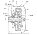
- the rotational power of the crankshaft 9 is transmitted to two clutches 21 and 22 (hereinafter referred to as a centrifugal clutch 21 and a multi-plate clutch 22) housed on the right side in the crankcase 2 and a transmission housed in the rear part in the crankcase 2. 4 is output to the engine output portion 23 on the left side of the rear portion of the crankcase 2.
- the engine output unit 23 is linked to a rear wheel 111 that is a driving wheel via a chain transmission mechanism 23a.
- the crankshaft 9 side may be referred to as the upstream side
- the engine output portion 23 side may be referred to as the downstream side.
- the centrifugal clutch 21 has a bottomed cylindrical shape that opens to the right, and is supported on the right end of the crankshaft 9 so as to be relatively rotatable, and on the inner peripheral side of the clutch outer 21a.
- the clutch inner 21b is supported on the right end portion of the crankshaft 9 so as to be integrally rotatable, and a plurality of centrifugal weights 21c are supported on the inner peripheral side of the clutch outer 21a so as to be able to expand and operate on the clutch inner 21b.
- a centrifugal oil filter 26 is formed on the right side of the clutch inner 21b.
- the centrifugal weights 21c are separated from the inner peripheral surface of the clutch outer 21a when the crankshaft 9 is stopped and rotated at a low speed, so that the centrifugal clutch 21 is in a disconnected state where power cannot be transmitted.
- Each centrifugal weight 21c is expanded as the rotational speed (rotational speed) of the crankshaft 9 increases, and frictionally engages with the inner peripheral surface of the clutch outer 21a at a predetermined rotational speed or more to transmit power to the centrifugal clutch 21. Make the connection possible.
- a cylindrical inner peripheral side collar portion 41 is provided on the right side at the center of the clutch outer 21a.
- a one-way clutch 40 is fitted on the outer periphery of the inner peripheral side collar portion 41.
- a cylindrical outer peripheral side collar portion 42 protruding from the left side of the clutch inner 21b is fitted.
- the outer peripheral side collar portion 42 includes an outer ring 44 in the one-way clutch 40.
- the one-way clutch 40 has a lock operation limiting device 47A described later.
- the one-way clutch 40 does not transmit torque even if the clutch inner 21b and the crankshaft 9 are forwardly rotated (corresponding to the rotation during engine operation) prior to the clutch outer 21a, and does not transmit torque to the clutch outer 21a. Thus, the clutch inner 21b and the crankshaft 9 are idled.
- the one-way clutch 40 has its rotational speed when the clutch outer 21a tries to rotate forward (or when the clutch inner 21b and the crankshaft 9 try to reversely rotate with respect to the clutch outer 21a) prior to the clutch inner 21b and the crankshaft 9. Is less than the predetermined value, the lock operation restricting device 47A operates to keep the free state and transmit torque without rotating the clutch outer 21a with respect to the clutch inner 21b and the crankshaft 9.
- the one-way clutch 40 enters a later-described one-way operation state when the rotational speed exceeds a predetermined value, and when the outer clutch member 21a tries to rotate forward in this state prior to the inner clutch member 21b and the crankshaft 9, a later-described roller 46
- the (moving body) is locked so that torque can be transmitted between the inner ring 43 and the outer ring 44.
- the clutch outer 21a, the clutch inner 21b, and the crankshaft 9 can be normally rotated integrally.
- a cylindrical transmission cylinder 21d extending leftward is provided on the left side of the center of the clutch outer 21a.
- a primary drive gear 21e is provided on the left end side of the transmission cylinder 21d so as to be integrally rotatable.
- the primary drive gear 21e meshes with a primary driven gear 22e supported on the right side of the main shaft 5 located behind the crankshaft 9 so as to be relatively rotatable.
- the main shaft 5 and the counter shaft 6 of the transmission 4 are arranged in order from the front side behind the crankshaft 9.
- the main shaft 5 and the counter shaft 6 are arranged with their respective rotation center axes C3 and C4 along the left-right direction (in parallel with the crank axis C1).
- a kick spindle 16 is disposed below the counter shaft 6.
- the right end portion of the main shaft 5 terminates to the left of the right end of the centrifugal clutch 21, and the multi-plate clutch 22 is coaxially supported on the right end portion.
- the multi-plate clutch 22 is a transmission clutch, and has a bottomed cylindrical shape that opens to the right and is supported on the right end of the main shaft 5 so as to be relatively rotatable, and an inner periphery of the clutch outer 22a. And a plurality of clutch plates 22c that are stacked in the axial direction between the outer clutch member 22a and the inner clutch member 22b.
- a primary driven gear 22e is supported on the left side of the bottom wall of the clutch outer 22a so as to be integrally rotatable.
- the multi-plate clutch 22 presses the clutch plates 22c by the urging force of the diaphragm spring 22d and frictionally engages them.
- the multi-plate clutch 22 temporarily releases the pressure contact of each clutch plate 22c in conjunction with a shift operation of a shift pedal (not shown), thereby making the shift change of the transmission 4 smoother.
- the transmission 4 includes a main shaft 5 and a counter shaft 6, and a transmission gear group 7 supported across both shafts 5 and 6.
- the rotational power of the crankshaft 9 is transmitted from the main shaft 5 to the countershaft 6 via an arbitrary gear of the transmission gear group 7.
- the left end portion of the counter shaft 6 protrudes to the left side of the rear portion of the crankcase 2 and becomes an engine output portion 23.
- the transmission gear group 7 is composed of gears corresponding to the number of shift stages respectively supported by the main shaft 5 and the counter shaft 6.
- the transmission 4 is configured as a constantly meshing type in which the corresponding gears of the transmission gear group 7 are always meshed between the main shaft 5 and the counter shaft 6.
- Each gear supported by the main shaft 5 and the counter shaft 6 includes a free gear that can rotate relative to the shaft that supports the gear, a fixed gear that can rotate integrally with the shaft that supports the gear, and the gear. And a slide gear that is spline-fitted to a shaft that supports the shaft.
- the transmission 4 moves the slide gear by the operation of a change mechanism (not shown), and selects a gear train corresponding to the gear position.
- a second gear train 7b, a fourth gear train 7d, a third gear train 7c, and a first gear train 7a are arranged in order from the left side of the transmission gear group 7.
- an ACG starter 27 (generator device) is coaxially supported.
- the ACG starter 27 is a three-phase AC generator motor, and functions as a starter motor that starts the engine 1 and also functions as an AC generator that generates power as the engine 1 is operated.
- the operation of the ACG starter 27 is controlled by an ECU (Electronic Control Unit) 60 (control device) shown in FIG.
- the ACG starter 27 is of a so-called outer rotor type, has a bottomed cylindrical shape that opens to the left, and is supported by the left end of the crankshaft 9 so as to be integrally rotatable, and an outer rotor 27a. And a stator 27b that is disposed on the inner peripheral side and is fixedly supported by the outer wall of the left case half 2a. A plurality of magnets 27c arranged in the circumferential direction are fixed to the inner peripheral side of the outer rotor 27a. A plurality of coils 27d arranged in the circumferential direction are formed on the outer peripheral side of the stator 27b.
- the ACG starter 27 has a rotor angle sensor unit 28 b that holds a plurality of rotor angle sensors 28 attached to a stator 27 b with fastening members 28 a such as screws.
- the rotor angle sensor 28 is used for energization control with respect to the coil 27d of the stator 27b, and one rotor angle sensor 28 is provided corresponding to each of the U phase, V phase, and W phase of the ACG starter 27.
- the rotor angle sensor 28 also functions as an ignition pulser (pulser sensor) that detects one circumferential position of the outer rotor 27a as an ignition timing.
- the rotor angle sensor 28 is configured by a Hall IC or a magnetoresistive (MR) element.
- the ACG starter 27 functions as a starter motor when the engine is started.
- the ACG starter 27 is supplied with electric power from a battery (not shown) via the motor drive circuit 61 of the ECU 60, and rotates the crankshaft 9 (forward rotation drive) to crank the engine 1.
- the rotation speed of the crankshaft 9 is less than the connection rotation speed of the centrifugal clutch 21, and the one-way clutch 40 does not transmit torque at this rotation (forward rotation). Therefore, the cranking rotational motion is not transmitted to the multi-plate clutch 22, the transmission 4, and the like on the downstream side of the transmission path from the clutch outer 21 a that is the driven member of the centrifugal clutch 21.
- the ACG starter 27 functions as an AC generator that is driven by the rotation of the crankshaft 9 to generate electric power when the start of the engine 1 is confirmed, for example, when the rotation speed of the crankshaft 9 becomes equal to or higher than idling. This power generation charges the battery and supplies power to various electrical components. At this time, the one-way clutch 40 does not transmit torque. However, if the rotation speed of the crankshaft 9 is equal to or higher than the connection rotation speed of the centrifugal clutch 21, the centrifugal clutch 21 enters a connected state and the crankshaft 9 is located downstream of the transmission path. Is transmitted.
- the kick spindle 16 along the left-right direction of the kick starter 16A of the engine 1 is disposed below the rear part of the crankcase 2.
- the right end portion of the kick spindle 16 protrudes to the right side of the rear portion of the crankcase 2, and the base end portion of the kick arm 16a is attached to the protruding portion.
- a kick drive gear 16b and a meshing mechanism 16c are coaxially supported on the left side of the kick spindle 16 facing the crankcase 2.
- the kick drive gear 16b rotates integrally with the kick spindle 16 via the meshing mechanism 16c only when the kick spindle 16 rotates in one direction by stepping on the kick arm 16a.
- the kick drive gear 16b meshes with the driven gear of the first gear train 7a.
- the rotational movement of the kick drive gear 16b is input as forward rotation to the clutch outer 21a of the centrifugal clutch 21 through the first speed gear train 7a, the main shaft 5, the multi-plate clutch 22, the primary driven gear 22e, and the primary drive gear 21e. .
- the one-way clutch 40 is in a one-way operation state, and when the one-way clutch 40 is locked by further forward rotation, forward torque is applied from the clutch outer 21a to the clutch inner 21b and the crankshaft 9. Can be transmitted. That is, cranking of the engine 1 by the kick starter 16A becomes possible.
- the limit of the lock operation of the one-way clutch 40 and the one-way operation state which will be described later, are switched at a rotation speed higher than the rotation range of the swingback and within the rotation assumption area of the kick starter 16A. Is set as follows.
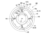
- the one-way clutch 40 has an annular shape coaxial with the crankshaft 9, and an inner ring 43 that is externally fitted to the inner peripheral side collar portion 41 of the clutch outer 21 a so as to be integrally rotatable,
- the outer ring 44 is provided integrally with the outer peripheral side collar portion 42 of the clutch inner 21 b, and the retainer 45 is disposed between the inner ring 43 and the outer ring 44.
- the axial direction of the one-way clutch 40 is referred to as a clutch axial direction
- the radial direction is referred to as a clutch radial direction
- the circumferential direction is referred to as a clutch circumferential direction.
- An arrow F in FIG. 5 indicates the normal rotation direction of the crankshaft 9.
- An arrow R in FIG. 5 indicates the reverse direction of the crankshaft 9.
- the outer ring 44 may not be integral with the outer collar portion 42 but may be fitted into the outer collar portion 42 so as to be integrally rotatable.
- the cage 45 includes a plurality of rollers 46 that are torque transmission elements between the inner ring 43 and the outer ring 44, and a plurality of coil springs (hereinafter simply referred to as springs) 47 that urge each roller 46 from the normal rotation direction to the reverse rotation direction. And a plurality of weights 48 that receive centrifugal force due to rotation on the inner ring 43 side and press each roller 46 outward in the clutch radial direction to move each roller 46 to a position where the one-way clutch 40 operates in one way. Hold at equal intervals in the direction.
- the retainer 45 can rotate integrally with the inner ring 43 by engaging a plurality of inner circumferential convex portions 45 a with the outer circumferential concave portion 43 a of the inner ring 43.
- a plurality of rollers 46, springs 47 (biasing members) and weights 48 together with the cage 45 also rotate integrally with the inner ring 43.
- the outer ring 44 forms a flat inner circumferential cylindrical surface 44a.
- the inner ring 43 forms a plurality of outer peripheral cam surfaces 43b that guide the roller 46, which is rolling between the inner ring 43 and the inner peripheral cylindrical surface 44a, to a non-rolling state (locked state).
- Each outer peripheral cam surface 43b is slightly inclined with respect to the tangential direction of the inner ring 43 so as to approach the inner peripheral cylindrical surface 44a toward the forward rotation direction, thereby forming a shape that functions as a one-way.
- the roller 46 is moved depending on the rotation direction of the inner ring 43, and the roller 46 is put in a rolling state (released state) without being pressed, or the roller 46
- a wedge-shaped space portion 49 is formed that enables switching between being pressed and placed in a non-rolling state (locked state).
- the roller 46 In each wedge-shaped space 49, the roller 46 is locked by the reverse rotation of the inner ring 43 with respect to the outer ring 44 (rotation in the direction of arrow R or forward rotation of the outer ring 44 with respect to the inner ring 43 (rotation in the direction of arrow F)). Thereby, torque transmission between the inner ring 43 and the outer ring 44 can be performed via the plurality of rollers 46.
- the rollers 46 In the normal rotation of the inner ring 43 with respect to the outer ring 44 (or the reverse rotation of the outer ring 44 with respect to the inner ring 43), the rollers 46 are in the released state in each wedge-shaped space 49, and torque transmission between the inner ring 43 and the outer ring 44 becomes impossible.
- the retainer 45 is formed with a plurality of weight operation surfaces 51 that guide each weight body 48 that receives centrifugal force when the inner ring rotates to move in the forward direction as the clutch body 48 moves outward in the clutch radial direction.
- a plurality of recesses 52 for entering the inner side in the clutch radial direction of the weight body 48 are formed in a portion located on the inner side in the clutch radial direction of each weight operating surface 51.
- each recess 52, the outer peripheral cam surface 43 b adjacent to the forward rotation direction of the recess 52, the weight operating surface 51, and the portion surrounded by the inner peripheral cylindrical surface 44 a of the outer ring 44 can move the roller 46 and the weight body 48. It is comprised as the accommodation space part 53 (space part) to accommodate.
- the forward rotation direction side of the accommodation space 53 is configured as a wedge-shaped space 49.
- each roller 46 is pushed in the reverse direction side of the accommodation space 53 by the urging force of the spring 47 when not pressed from the weight body 48.
- the outer peripheral surface of the roller 46 forms a gap between at least one of the outer peripheral cam surface 43 b and the inner peripheral cylindrical surface 44 a and the outer peripheral surface of the roller 46.
- the roller 46 is not pressed against the wedge-shaped space 49 and can always roll. That is, when each roller 46 is in a position where it is pushed into the reverse direction side of the accommodation space 53, there is no one-way operation.
- each weight body 48 moves to the outer peripheral side along the weight operation surface 51, and the corresponding roller 46 is moved. It is moved in the forward rotation direction against the urging force of the spring 47.
- the roller 46 moves by a predetermined amount in the forward rotation direction and reaches a predetermined position (one-way operation position) of the outer peripheral cam surface 43b, so that the roller 46 is in contact with the outer peripheral cam surface 43b and the inner peripheral cylindrical surface 44a. Become. In this state, when the inner ring 43 rotates in the reverse direction, the roller 46 is brought into pressure contact with the wedge-shaped space portion 49 and enters a non-rolling state.
- the roller 46 is moved by a predetermined amount in the forward rotation direction by a pressure generated by the movement of the weight body 48 in the accommodating space 53 to the outside in the clutch radial direction and reaches a predetermined position on the outer circumferential cam surface 43b.
- the state in contact with the surface 43b and the inner peripheral cylindrical surface 44a is referred to as a one-way operation state of the one-way clutch 40.
- the roller 46 is pressed against the wedge-shaped space 49 by the reverse rotation of the inner ring 43 with respect to the outer ring 44 (or the normal rotation of the outer ring 44 with respect to the inner ring 43) from the one-way operation state, and the non-rolling state is established between the inner ring 43 and the outer ring 44.
- the fact that torque transmission is possible is referred to as locking operation of the one-way clutch 40.
- the roller 46 In the normal rotation of the inner ring 43 with respect to the outer ring 44 (or the reverse rotation of the outer ring 44 with respect to the inner ring 43), the roller 46 is not pressed against each wedge-shaped space 49 regardless of whether or not the one-way operation is performed, and can always roll. (The one-way clutch 40 is not locked), and torque transmission between the inner ring 43 and the outer ring 44 becomes impossible.
- each roller 46 When centrifugal force enough to move each roller 46 to the position where the one-way operation state is achieved against the urging force of the spring 47 does not act on each weight 48 (corresponding to when the clutch outer 21a stops rotating and rotates at a low speed).
- the one-way clutch 40 is not in a one-way operation state, and the roller 46 does not come into pressure contact with the wedge-shaped space 49 even when the inner ring 43 is rotated reversely with respect to the outer ring 44 (or the outer ring 44 is rotated forward with respect to the inner ring 43).
- the torque transmission between the inner ring 43 and the outer ring 44 becomes impossible.
- the weight 48, the recess 52 of the inner ring 43 that guides the movement of the weight 48, the spring 47, the retainer 45 that holds the spring 47, and the roller 46 limit the locking operation of the one-way clutch 40 according to the rotational speed of the inner ring 43.
- the lock operation limiting device 47A is configured.
- the cage 145 of the one-way clutch 140 supports a plurality of weight bodies 146 (moving bodies) that are torque transmission elements between the inner ring 43 and the outer ring 44 so as to be swingable at equal intervals in the clutch circumferential direction.
- Each weight main body 146 that receives the centrifugal force due to the rotation of the inner ring 43 is swung toward the wedge-shaped space 49. That is, the weight main body 146 serves as a torque transmitting element that is press-contacted between the inner ring 43 and the outer ring 44 and a weight body that operates by receiving centrifugal force.
- Each weight main body 146 integrally has a swing arm 146a extending incline in the forward rotation direction and on the inner peripheral side of the clutch.
- the tip end portion 146b of the swing arm 146a is supported by the retainer 145 so as to be swingable.
- a plurality of torsion coil springs (hereinafter simply referred to as springs) 147 for urging the weight main body 146 to the side away from the wedge-shaped space 49 in the reverse rotation direction are attached to the distal end portion 146b of the swing arm 146a.
- the cage 145 can rotate integrally with the inner ring 43.
- a plurality of weight main bodies 146 and springs 147 (biasing members) together with the cage 145 also rotate integrally with the inner ring 43.
- Each weight main body 146 is pushed into the corresponding recess 52 by the urging force of the spring 147 when a centrifugal force of a predetermined level or more is not applied, such as when the clutch outer 21a stops rotating or rotates at a low speed. At this time, each weight main body 146 is detached from the wedge-shaped space 49, and a gap is formed between the outer peripheral cam surface 43b and the inner peripheral cylindrical surface 44a. In this state, regardless of whether the inner ring 43 rotates forward or backward, the weight main body 146 does not contact the outer peripheral cam surface in the wedge-shaped space 49, and the one-way operation state is not achieved.
- each weight body 146 swings toward the corresponding wedge-shaped space 49 and comes into contact with the outer peripheral cam surface 43b and the inner peripheral cylindrical surface 44a (locking). Operation). In this state, the weight main body 146 is pressed against the wedge-shaped space 49 by the reverse rotation of the inner ring 43 with respect to the outer ring 44 (or the normal rotation of the outer ring 44 with respect to the inner ring 43), and torque transmission between the inner ring 43 and the outer ring 44 becomes possible.
- the weight main body 146 In the normal rotation of the inner ring 43 with respect to the outer ring 44 (or the reverse rotation of the outer ring 44 with respect to the inner ring 43), the weight main body 146 is not pressed against the wedge-shaped space 49 regardless of the rotational speed, and torque transmission between the inner ring 43 and the outer ring 44 is achieved. Becomes impossible.
- the weight body 146, the swing arm 146a, the spring 147, and the retainer 145 that holds the spring 147 are configured to restrict the lock operation of the one-way clutch 140 according to the reverse rotation speed of the inner ring 43 (the lock operation restriction device 47A).
- the weight main body 146 has the functions of both the weight body 48 and the roller 46 of the first embodiment.
- the ECU 60 includes a motor drive circuit 61 that controls driving and power generation of the ACG starter 27, an idle stop control unit 62 that automatically stops the engine 1 (idle stop), and an ACG starter immediately after the idle stop. And a swing back control unit 63 that performs reverse rotation (swing back) of the crankshaft 9 by 27 reverse rotation driving.
- the ECU 60 includes a throttle sensor 31 that detects the opening of a throttle valve (not shown) of the throttle body 18, a vehicle speed sensor 32 that detects the vehicle speed from the rotational speed of the wheels, and a warm-up state of the engine 1.
- a temperature sensor 33 that detects the oil temperature and a battery sensor 34 that detects the battery current and voltage as the state of charge of the battery are connected.
- the rotor angle sensor 28 also serves as a crank angle sensor that detects a crank rotation speed and a rotation angle.
- the ECU 60 is connected to an ignition device 35 including an ignition plug 17 and a fuel injection device 36 including an injector 18a of the throttle body 18, and the occupant selects whether to perform idle stop control.
- An idle stop switch 37 to be activated and an indicator 38 that is lit when idle stop control is selected or idle stop is connected.
- the motor drive circuit 61 includes, for example, a power FET (Field-Effect-Transistor), rectifies the three-phase alternating current generated by the ACG starter 27, and regulates the battery power when driving the ACG starter 27. Supply.
- a power FET Field-Effect-Transistor
- the idle stop control unit 62 automatically stops the engine 1 by stopping the ignition of the spark plug 17 and the fuel injection of the injector 18a when the automatic stop permission condition of the engine 1 is satisfied when the idle stop control is selected. stop).
- the idle stop control unit 62 drives the ACG starter 27 to crank the engine 1 when the restart permission condition of the engine 1 is satisfied, and also performs ignition of the spark plug 17 and fuel injection of the injector 18a.
- the engine 1 is restarted and the engine 1 is automatically restarted.
- the ECU 60 performs the idle stop control only when it is recognized that the state of charge of the battery is sufficient to restart the engine 1.
- the swing back control unit 63 drives the ACG starter 27 in reverse to improve the restartability of the engine 1 after idling stop, and the crankshaft 9 is in front of the compression top dead center just before idling stop (during reverse rotation). Reverse to the rotation angle (swing back).
- the swingback control unit 63 extends the running distance of the crankshaft 9 when the engine 1 is restarted, and reverses the crankshaft 9 to a position where the forward rotation torque for getting over the compression top dead center is small. Thereafter, the idle stop control unit 62 drives the ACG starter 27 to rotate in the forward direction, causes the crankshaft 9 to rotate in the forward direction again, and operates the ignition device 35 and the fuel injection device 36 again to restart the engine 1.
- the swingback control unit 63 includes a stage determination unit 64, a stage passage time detection unit 65, a reverse rotation control unit 66, and a duty ratio setting unit 67.
- the stage determination unit 64 divides one revolution of the crankshaft 9 into 36 stages # 0 to # 35 based on the output signal of the rotor angle sensor 28, and generates a pulse signal generated by the rotor angle sensor 28 as an ignition pulser.
- the current stage is determined using the detection timing as a reference stage (stage # 0).
- the stage passage time detection unit 65 detects the passage time ⁇ tn of this stage based on the time from when the stage determination unit 64 determines a new stage until the next stage is determined.
- the reverse rotation control unit 66 generates a reverse rotation drive command for the ACG starter 27 based on the determination result by the stage determination unit 64 and the passage time ⁇ tn detected by the stage passage time detection unit 65.
- the duty ratio setting unit 67 dynamically controls the duty ratio of the gate voltage supplied to each power FET of the motor drive circuit 61 based on the determination result by the stage determination unit 64.
- FIG. 11A shows the relationship between the cranking torque (reverse load) required for reversing the crankshaft 9 and the crank angle.
- the cranking torque suddenly increases immediately before reaching the compression top dead center (during reverse rotation).
- FIG. 11B shows the relationship between the crank angle and the stage.
- FIG. 11C shows the change in the angular velocity of the crankshaft 9 during reverse rotation.
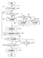
- step S1 swing back control unit 63 refers to the current stage already determined in stage determination unit 64 in steps S2 and S3. If the current stage is any one of stages # 0 to # 11, the process proceeds to step S4. If the current stage is any one of stages # 12 to # 32, the process proceeds to step S5. If the current stage is other than that (that is, any one of stages # 33 to # 35), the process proceeds to step S6. In step S4 and step S6, the duty ratio setting unit 67 sets the duty ratio of the drive pulse to 70%. In step S5, the duty ratio setting unit 67 sets the duty ratio of the drive pulse to 80%.
- step S7 the motor drive circuit 61 starts reverse energization by controlling each power FET with the duty ratio set in any of steps S4 to S6.
- step S8 the passage time ⁇ tn of the passed stage #n is measured by the stage passage time detector 65.
- step S9 the reverse rotation control unit 66 determines whether or not the crankshaft 9 has passed stage # 0 (ie, near the top dead center). If it has not passed stage # 0, in step S11, the ratio between the passing time ⁇ tn of stage #n that passed immediately before and the passing time ⁇ tn-1 of stage # (n ⁇ 1) that passed immediately before “#” “ ⁇ tn / ⁇ tn ⁇ 1” (hereinafter referred to as a passing time ratio) is compared with a reference value (4/3 in the present embodiment). If the passage time ratio “ ⁇ tn / ⁇ tn ⁇ 1” does not exceed the reference value, the process returns to step S2 to continue the reverse drive, and the above-described processes are repeated in parallel.
- a passing time ratio 4/3 in the present embodiment
- the engine stop position that is, the reverse rotation start position is from an intermediate position (exhaust top dead center) between the previous compression top dead center and the next compression top dead center.
- the side near the next compression top dead center in other words, when it is in the process from passing through the exhaust top dead center (during normal rotation) to reaching the compression top dead center, the ACG starter 27 has a duty of 70%.
- the crankshaft 9 can pass through the stage # 0 (exhaust top dead center) despite being driven in reverse at a ratio.
- step S9 the process proceeds to step S10, and it is determined whether or not the crankshaft 9 has reached stage # 32. If it is determined that the crankshaft 9 has reached the stage # 32, the reverse energization is stopped in step S12. Thereafter, the crankshaft 9 is further rotated in the reverse direction by the inertial force and then stopped.
- the reverse rotation start position is closer to the previous compression top dead center than the intermediate position between the previous compression top dead center and the next compression top dead center,
- the ACG starter 27 is driven in reverse at a duty ratio of 70%, so FIG.
- the reverse load increases immediately before reaching stage # 0 (during reverse rotation), and the angular velocity of the crankshaft 9 decreases.
- step S11 when it is determined that the passage time ratio “ ⁇ tn / ⁇ tn ⁇ 1” is 4/3 or more which is the reference value, the reverse energization is stopped in step S12, and substantially simultaneously with this, the crankshaft 9 The reverse rotation stops.
- the crankshaft 9 it is determined whether or not the crankshaft 9 has passed the top dead center equivalent angle and whether or not the angular velocity of the crankshaft 9 has decreased during reverse rotation after the engine is stopped. If the crankshaft 9 passes the top dead center at the time of reverse rotation, the reverse rotation energization is terminated immediately thereafter, and the reverse rotation energization is also ended when the angular velocity of the crankshaft 9 is reduced by a predetermined amount due to an increase in the reverse load. . As a result, regardless of the reverse rotation start position, the crankshaft 9 can be returned to a position before the previous compression top dead center (during reverse rotation) and to a low compression reaction force (cylinder internal pressure).
- the angular speed of the crankshaft 9 is detected based on the output of the rotor angle sensor 28 that detects the rotor angle (stage) of the ACG starter 27, so the angle of the crankshaft 9 is detected. There is no need to provide a separate crank angle sensor to reduce the number of parts.
- the engine 1 restricts the lock operation for the torque transmission in the one-way clutches 40 and 140 when the crankshaft 9 is reversely rotated at a low speed in the swingback control in which the crankshaft 9 is reversely rotated to a predetermined position after the engine is stopped. It has devices 47A and 147A.
- the engine brake can be used without greatly changing the configuration of the existing internal combustion engine having the centrifugal clutch 21 and the one-way clutches 40 and 140 in the transmission path from the crankshaft 9 to the engine output unit 23, and the centrifugal clutch.
- the swing start control by the ACG starter 27 is performed while suppressing the loss of the reverse rotation torque of the ACG starter 27, while the kick starter 16A using the driven member (clutch outer 21a) on the engine output unit 23 side of 21 can be installed. It is possible to reduce the starting torque load of the ACG starter 27 when the engine is restarted.
- the lock operation restriction device 247A of the third embodiment is different from the one-way clutch 40 in that the weight body 48 is eliminated and an elastic plate 48 ′ made of a leaf spring, a rubber plate or the like is provided in the open portion of the recess 52 in the clutch circumferential direction. Install along. The roller 46 moves from the state on the elastic plate 48 ′ in the wedge-shaped space 49 according to the rotation direction of the inner ring 43.
- a lock operation restriction device 247A that has the restriction piece 257 and moves the restriction piece 257 to restrict the lock operation of the one-way clutch 40 ′ will be described.
- the lock operation restriction unit (not shown) of the swing back control unit 63 senses an electric signal (“swing back signal” in FIG. 13) corresponding to the reverse rotation instruction signal for the ACG starter 27, the lock operation restriction device 247A It is driven by the lock operation restricting unit to restrict the lock operation of the one-way clutch 40 ′.
- the lock operation restriction device 247A extends between the solenoid 255 that is energized and controlled by the lock operation restriction unit, the restriction member 256 that is activated by the protrusion of the plunger 255a when the solenoid 255 is energized, and the plunger 255a and the restriction member 256.
- the solenoid 255 is supported in the right case cover 25 and causes the plunger 255a to protrude leftward.
- the solenoid 255 is a push type that causes the plunger 255a to protrude when energized.
- the input end side of the rocker arm 256a abuts on the distal end portion of the plunger 255a.
- the output end of the rocker arm 256 a abuts on the left side surface of the limiting member 256.
- the limiting member 256 is urged to the left by the urging member 258.
- the urging member 258 is a coil spring that is fitted in a stretchable manner with a gap on the outer periphery of the transmission cylinder 21d. As shown by “solenoid input” in FIG. 13, the energization signal to the solenoid 255 is turned “ON” together with the “swing back signal”, and the solenoid 255 is energized by the lock operation restriction unit.
- the limiting member 256 is provided with a limiting piece 257 that protrudes to the right. When the limiting member 256 moves to the right, the limiting piece 257 is inserted into the wedge-shaped space 49.
- the restricting piece 257 is inserted into the wedge-shaped space 49 with the roller 46 (moving body) pushed in the reverse direction as shown in FIG. 16, and the roller 46 moves in the forward direction (the one-way clutch 40 ′ is one-way). Limit the movement to the position where it will be activated.
- the restricting piece 257 has an inclined side 257a that can be brought into sliding contact with the roller 46 when inserted into the wedge-shaped space 49, and can facilitate the quick movement of the roller 46 while facilitating insertion.
- the lock operation restriction device 247A disables the lock operation of the one-way clutch 40 ′ when “swing back” and “solenoid input” are “ON”, as indicated by “lock operation” in FIG. When the “swing back” and “solenoid input” are “OFF”, the one-way clutch 40 ′ can be locked.
- the lock operation limiting device is configured so that the limiting piece 257 is moved to the forward rotation direction side of the roller 46 in the wedge-shaped space 49 in a state where the roller 46 is pushed in the forward rotation direction (including the one-way operation state of the one-way clutch 40 ′). Even when the roller 46 is inserted, the roller 46 may be moved in the reverse rotation direction while sliding the inclined side 257a on the roller 46, and the change to the one-way operation state of the one-way clutch 40 ′ may be limited as described above. . Thereby, it can be used for releasing the lock operation of the mechanical one-way clutch.
- both the lock operation restriction devices 47A and 247A may be employed together to control the energization to the solenoid 255. . That is, the lock operation restriction device 247A may be applied to the one-way clutch 40.
- the lock operation limiting device may be configured to limit the movement of the weight body 48 instead of the moving body (roller 46). Further, the one-way clutch 140 can be combined with the lock operation limiting device 247A.
- the lock operation restriction device 347A includes an electromagnet 355 that is energized and controlled by a lock operation restriction unit (not shown), a restriction member 356 that is activated by energization of the electromagnet 355, and a rocker arm 356a that extends between the electromagnet 355 and the restriction member 356.
- the electromagnet 355 is supported in the right case cover 25 and is adjacent to the left side of the magnet 356b built in the input end side of the rocker arm 356a.
- the output end of the rocker arm 356 a contacts the left side surface of the limiting member 356.
- a magnet 356b that can be attracted by magnetization of the electromagnet 355 is built in the tip of the rocker arm 356a.
- the limiting member 356 is disposed adjacent to the left side of the one-way clutch 40 and causes the limiting piece 257 to protrude rightward.
- the restricting member 356 is urged to the left by the urging member 258, and the left side surface is brought into contact with the output end portion of the rocker arm 356a.
- the rocker arm 356a separates the input-side magnet 356b from the electromagnet 355 by a predetermined amount.
- the mechanical one-way clutch may be used for releasing the lock operation.
- the above configuration may be applied to the one-way clutches 40 and 140, and the lock operation restriction devices 47A and 147A may be used in combination.
- FIG. 17 shows a setting concept of the operation limit of the one-way clutch according to the embodiment of the present invention, where the horizontal axis is the rotation speed of the crankshaft, the region where the operation limit of the one-way clutch is applied, the rotation speed of the swingback, and the kick The crank rotation speed is shown.
- the width of the rotational speed of the swingback is assumed in consideration of the phase of the crank and the like, and the width of the crank rotational speed due to the kick is assumed including variations in kicks of general drivers.
- the concept of setting the operation limit depends on the reverse rotation speed in the case of swingback, but in the case of the rotation action type that utilizes centrifugal force, the absolute value of the rotation speed regardless of the forward and reverse rotation. Depends on. For this reason, the setting concept is expressed using the absolute value of the rotational speed of the crankshaft on the horizontal axis.
- the one-way clutch lock operation limit and the one-way operation state are switched at a rotation speed higher than the rotation speed range of the swingback and at a rotation speed within the assumed rotation range of the kick starter 16A. Is set.
- the kick drive when starting with the kick starter, can be effectively operated in the upper rotation speed range (the region indicated by the solid line) by the one-way operation state in the expected kick starter rotation range. it can.
- a device that electrically restricts the lock operation instead of the mechanical rotation speed operation type lock operation restriction device 47A.
- the lock operation when the swing back is not performed, the lock operation is not limited, and the one-way operation state can be always set by electrical control, and the kick starter rotation assumed range It is possible to make the kick drive work effectively in all of the above (including the dotted line).
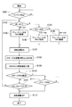
- the swingback control unit 63 includes a stage determination unit 64, a stage passage time detection unit 65, a reverse rotation control unit 66, a duty ratio setting unit 67, and a lock release control unit 68.
- the lock release control unit 68 performs a one-way clutch lock release confirmation process described later.
- step S101 to step S108 of this embodiment is the same as the operation from step S1 to step S8 described with reference to FIG. 10 for the second embodiment of the one-way clutch, the description thereof is omitted.
- step S109 a one-way clutch lock release confirmation step, which will be described in detail later, is performed.
- step S110 to step S113 are the same as the operations from step S9 to step S12 described with reference to FIG. 10 for the second embodiment of the one-way clutch, and thus the description thereof is omitted.
- lock release control unit 68 first resets timekeeping information “ ⁇ t” in step S191 and resets stage count information “ ⁇ n” in step S192.
- step S193 it is determined whether or not “ ⁇ t” exceeds a predetermined time T (for example, 35 msec). If “ ⁇ t” exceeds the predetermined time T, it is then determined in step S194 whether “ ⁇ n” exceeds 2. That is, it is determined whether or not it has rotated two stages after a predetermined time T after the reverse rotation drive command of the ACG starter 27.
- step S195 the process proceeds to step S91 described later, and if “NO”, the process proceeds to step S195.
- steps S195 to S199 assuming that the one-way clutch 40 has been locked since the idling stop, the reverse energization is stopped in step S195 and the forward energization is started in step S196. This forward energization is performed until the rotation angle of the crankshaft 9 reaches at least the next stage # n + 1 from the current stage #n (step S197).
- the locked state of the one-way clutch 40 in this case assumes that the roller 46 is already in a non-rolling state in an unexpected situation in the wedge-shaped space 49, for example, at an idle stop immediately after engine braking.
- the forward rotation energization in step S197 causes the inner ring 43 together with the crankshaft 9 to rotate forward by at least a predetermined angle ⁇ with respect to the outer ring 44 (see FIG. 22C).
- the predetermined angle ⁇ is set to an angle sufficient to release the pressure contact of the roller 46.
- the predetermined angle ⁇ is set to a rotation angle corresponding to at least one stage of the crankshaft 9, that is, a rotation angle of at least 10 degrees.
- step S198 forward energization is stopped in step S198, and reverse energization is started again in step S199. Then, the process returns to step S191, and the processes of steps S191 to S194 are performed again. If “YES” in the step S194, the one-way clutch 40 is unlocked at the time of idling stop. If “NO” remains in step S194, the processes in steps S195 to S199 are repeated again. Even if these processes are repeated a predetermined number of times, if the lock at the time of idling stop of the one-way clutch 40 is not released, a notifying means (not shown) is operated because an abnormality has occurred. It should be noted that after the idle stop, the control may always be performed so that the ACG starter 27 is rotated forward by one stage and then reversely rotated, and thereafter the process returns to step S191 regardless of the determination in step S194.
- steps S91 to S96 processing is performed when the one-way clutch 40 is locked during swingback.
- step S91 the decrease in the angular speed of the crankshaft 9 after the start of reverse rotation is due to reaching a point before compression top dead center (at the time of reverse rotation), or due to an unexpected lock state of the mechanical one-way clutch 40.
- the second reference value X is a value (for example, 2/1) larger than the reference value (4/3), and indicates that the angular velocity of the crankshaft 9 has decreased relatively abruptly.
- the passage time ratio “ ⁇ tn / ⁇ tn ⁇ 1” of the crankshaft 9 is monitored, and before the crankshaft 9 is reversely rotated to a predetermined angle, whether or not the one-way clutch 40 is unlocked is determined. Determine whether.
- the increase in the reverse rotation load when the one-way clutch 40 is in the locked state is expected to be the latter case because the reverse rotation load is much higher than the increase in the reverse rotation load when the crankshaft 9 is in the process of reaching the compression top dead center.
- the second reference value X corresponding to the passing time ratio “ ⁇ tn / ⁇ tn ⁇ 1” based on the maximum reverse load, the measured value of the passing time ratio “ ⁇ tn / ⁇ tn-1” exceeds the second reference value X. Whether or not the one-way clutch 40 is unlocked can be determined based on whether or not it is engaged.
- step S91 If it is determined in step S91 that the passage time ratio “ ⁇ tn / ⁇ tn ⁇ 1” is equal to or smaller than the second reference value X, the process after step S110 is performed assuming that the locked state of the one-way clutch 40 is released. Is called. The change in the angle of the crankshaft 9 at this time is shown in FIG.
- step S91 If it is determined in step S91 that the passage time ratio “ ⁇ tn / ⁇ tn ⁇ 1” exceeds the second reference value X, it is assumed that the one-way clutch 40 is in the locked state and the reverse energization is stopped in step S92.
- step S93 normal energization is started. This forward energization is performed until the rotation angle of the crankshaft 9 reaches from the current stage #n to at least the next stage # n + 1 as in step S197 (step S94).
- step S94 causes the inner ring 43 together with the crankshaft 9 to rotate forward by at least a predetermined angle ⁇ with respect to the outer ring 44 (see FIG. 22D).
- step S95 the forward energization is stopped in step S95, and the reverse energization is started again in step S96. Then, the process returns to step S91 to determine again whether or not the passage time ratio “ ⁇ tn / ⁇ tn ⁇ 1” exceeds the second reference value X. If the passage time ratio “ ⁇ tn / ⁇ tn ⁇ 1” is equal to or smaller than the second reference value X in this determination, it is determined that the one-way clutch 40 is unlocked, and the process proceeds to step S96 and subsequent steps.
- the change in the angle of the crankshaft 9 at this time is shown in FIG.
- step S91 If it is determined again in step S91 that the passage time ratio “ ⁇ tn / ⁇ tn ⁇ 1” remains higher than the second reference value X, the processes in steps S92 to S96 are repeated again. If the passage time ratio “ ⁇ tn / ⁇ tn ⁇ 1” remains above the second reference value X even after repeating these processes a predetermined number of times, a notifying means (not shown) is operated as an abnormality has occurred.
- the internal combustion engine in the above embodiment includes the ACG starter 27 that also serves as the starting motor, the centrifugal clutch 21 provided in the transmission path from the crankshaft 9 to the engine output unit 23, and the engine output unit of the centrifugal clutch 21.
- a clutch outer 21a that is a driven member on the 23 side is supported on an extension shaft 9d that is one of the transmission shafts of the transmission path, and torque is not transmitted to the clutch outer 21a when the extension shaft 9d rotates forward with respect to the clutch outer 21a.
- the one-way clutch 40 capable of transmitting torque to the clutch outer 21a during reverse rotation of the extension shaft 9d with respect to the clutch outer 21a, and the ECU 60 that drives and controls the ACG starter 27 are provided. Swing back control to reverse the That during reverse rotation of extension shaft 9d, it has a lock operation restricting device 47A for limiting the locking operation for the torque transmission.
- the engine brake can be used without greatly changing the configuration of the existing internal combustion engine having the centrifugal clutch 21 and the one-way clutch 40 in the transmission path from the crankshaft 9 to the engine output unit 23, and the centrifugal clutch While it is possible to equip the kick starter 16A using the 21 driven members, the swing back control by the ACG starter 27 that also serves as the starter motor can be performed while suppressing the loss of the reverse rotation torque of the ACG starter 27. The starting torque load of the ACG starter 27 at the time of starting can be reduced.
- the ECU 60 when the reverse rotation of the ACG starter 27 is not normally performed after the reverse rotation instruction to the ACG starter 27 in the swing back control, the ECU 60 temporarily rotates the ACG starter 27 once as the unlocking operation of the one-way clutch 40. After that, it has a lock release control unit 68 that reversely rotates the ACG starter 27 again.
- the one-way clutch 40 is locked due to an unforeseen situation during the swing-back operation, and a means for releasing this is provided to increase the reliability of the swing-back operation.
- the ACG starter 27 can be rotated forward once and then the ACG starter 27 can be reversed again to release the locked state of the torque transmission element. The loss of reverse torque can be suppressed and the reliability of the swingback operation can be increased.
- the present invention is not limited to the above-described embodiment, and for example, at least one of the centrifugal clutch 21 and the ACG starter 27 may be supported on a different shaft instead of being coaxial with the crankshaft 9.
- the present invention may be applied to an engine having a stepped or continuously variable automatic transmission instead of the manual transmission 4.
- it is good also as a structure which moves the limiting members 256 and 356 inserted in a one-way clutch with a mechanical centrifugal mechanism.
- the inner ring 43 of the one-way clutch is externally fitted on the clutch outer 21a side of the centrifugal clutch 21, and the outer ring 44 of the one-way clutch is fitted on the clutch inner 21b side.
- the arrangement is not limited to this, and the inner ring of the one-way clutch may be mounted on the clutch inner side of the centrifugal clutch, and the outer ring of the one-way clutch may be mounted on the outer clutch side of the centrifugal clutch.
- the mechanism corresponding to the lock operation limiting device based on the rotation speed of the first embodiment, the second embodiment, and the fifth embodiment is provided on the outer ring side, and the rotation speed of the outer ring becomes equal to or higher than a predetermined speed. It is replaced with a mechanism that enables the locking operation.
- the present invention is not limited to motorcycles and may be applied to three-wheel or four-wheel small vehicles.
- the present invention is not limited to an engine in which a cylinder protrudes in front of the crankcase, and may be applied to an engine in which the cylinder is raised above the crankcase.
- the structure in the said embodiment is an example of this invention, A various change is possible in the range which does not deviate from the summary of this invention.
Abstract
An internal combustion engine (1) has a lock operation limiting device (47A) for limiting a lock operation for torque transmission in a one-way clutch (40) when a crankshaft (9) is rotated in reverse during swing-back control. The lock operation limiting device (47A) limits the lock operation of the one-way clutch (40) in accordance with the reverse rotation speed of the crankshaft (9) during swing-back control.
Description
本発明は、内燃機関に関する。
本願は、2013年2月6日に出願された日本国特許出願2013-021717号、及び2013年2月6日に出願された日本国特許出願2013-021718号に基づき優先権を主張し、その内容をここに援用する。 The present invention relates to an internal combustion engine.
This application claims priority based on Japanese Patent Application No. 2013-021717 filed on Feb. 6, 2013 and Japanese Patent Application No. 2013-021718 filed on Feb. 6, 2013. The contents are incorporated herein.
近年、環境への配慮や省エネルギーの観点から、車両の停止時等の所定の条件下でエンジンを自動停止させると共に、スロットルを開く等の所定の発進操作により自動的にエンジンを再始動させる、自動停止・始動制御(いわゆるアイドルストップ制御)を採用した内燃機関が増えている。
上記制御では、始動電動機兼用の発電機装置が活用されている。この装置においては、エンジンの自動停止直後にクランクシャフトを所定位置まで逆転させ(スイングバック)、次のエンジン再始動に備えるものがある(例えば、特許文献1参照)。これは、エンジン再始動時のクランクシャフトの助走距離を伸ばし、圧縮上死点を乗り越えるためのトルクを極力削減するために有効である。 In recent years, from the viewpoint of environmental considerations and energy saving, the engine is automatically stopped under a predetermined condition such as when the vehicle is stopped, and the engine is automatically restarted by a predetermined starting operation such as opening the throttle. An increasing number of internal combustion engines employ stop / start control (so-called idle stop control).
In the above control, a generator device also used as a starter motor is utilized. Some of these devices reverse the crankshaft to a predetermined position (swing back) immediately after the engine is automatically stopped (see, for example, Patent Document 1). This is effective in extending the run distance of the crankshaft when the engine is restarted and reducing the torque required to overcome the compression top dead center as much as possible.
また、小型車両用エンジンには、クランクシャフトから機関出力部への伝動経路に遠心クラッチを有し、遠心クラッチにおける機関出力部側の被動部材を、前記伝動経路の伝動軸上にワンウェイクラッチを介して支持したものがある(例えば、特許文献2参照)。ワンウェイクラッチは、機関運転時のクランクシャフトに連動する伝動軸の正転トルクを被動部材に伝達せず、伝動軸の逆転トルクを被動部材に伝達する。すなわち、被動部材の正転トルクでクランクシャフトを正転させることが可能であり、エンジンブレーキを利用可能になると共に、被動部材を用いたキックスターターを装備することが可能になる。
The small vehicle engine has a centrifugal clutch in the transmission path from the crankshaft to the engine output section, and the driven member on the engine output section side of the centrifugal clutch is disposed on the transmission shaft of the transmission path via a one-way clutch. (For example, refer to Patent Document 2). The one-way clutch transmits the reverse rotation torque of the transmission shaft to the driven member without transmitting the normal rotation torque of the transmission shaft linked to the crankshaft during engine operation to the driven member. That is, the crankshaft can be normally rotated by the normal rotation torque of the driven member, and the engine brake can be used and a kick starter using the driven member can be provided.
しかしながら、上記後者の構成で上記前者のスイングバック制御を行うと、クランクシャフトの逆転に連動する伝動軸の逆転トルクが被動部材に伝達され、遠心クラッチよりも機関出力部側の軸やギヤ等を駆動させたり、駆動車輪を後転させる力が伝達されるなど、発電機装置の逆転トルクをロスし易いという課題がある。
また、所定回転速度以上で逆転トルクを伝達可能とする、回転速度作動型のワンウェイクラッチを採用することも考えられる。機械式の回転速度作動型ワンウェイクラッチの場合、スイングバック作動時に不測の状況によるワンウェイクラッチのロックも想定し、これを解除する手段を有してスイングバック動作の確実性を高めることが期待される。 However, when the former swingback control is performed in the latter configuration, the reverse torque of the transmission shaft that is linked to the reverse rotation of the crankshaft is transmitted to the driven member, and the shaft, gear, etc. on the engine output side than the centrifugal clutch There exists a subject that it is easy to lose the reverse rotation torque of a generator device, such as transmitting the force which drives or drives a driving wheel backward.
It is also conceivable to employ a rotation speed actuated one-way clutch that can transmit reverse torque at a predetermined rotation speed or higher. In the case of a mechanical rotation speed actuated one-way clutch, it is expected that the one-way clutch will be locked due to unforeseen circumstances at the time of swingback operation, and that there is a means to release this, and the reliability of the swingback operation is expected to be increased .
本発明の態様は上記事情に鑑みてなされたもので、アイドルストップ時に発電機装置の駆動によるスイングバックを行うと共に、クランクシャフトから機関出力部への伝動経路の伝動軸上に遠心クラッチの被動部材をワンウェイクラッチを介して支持した内燃機関において、スイングバック時の発電機装置の逆転トルクのロスを抑えると共に、スイングバック動作の確実性を高めることを目的とする。
The aspect of the present invention has been made in view of the above circumstances, and performs a swingback by driving a generator device during idle stop, and a driven member of a centrifugal clutch on a transmission shaft of a transmission path from a crankshaft to an engine output unit In the internal combustion engine that supports the engine via a one-way clutch, an object is to reduce loss of reverse torque of the generator device during swingback and to increase the reliability of the swingback operation.
上記目的を達成するために、本発明の態様に係る内燃機関は、以下の構成を採用する。
(1)本発明の一態様に係る内燃機関は、始動電動機兼用の発電機装置と;クランクシャフトから機関出力部への伝動経路に設けられる遠心クラッチと;前記遠心クラッチの前記機関出力部側の被動部材を前記伝動経路の伝動軸上に支持し、前記被動部材に対する前記伝動軸の正転時には前記被動部材にトルクを伝達せず、前記被動部材に対する前記伝動軸の逆転時には前記被動部材にトルクを伝達可能なワンウェイクラッチと;を備え、機関停止後に前記クランクシャフトを所定位置まで逆転させるスイングバック制御における前記伝動軸の逆転時に、前記ワンウェイクラッチにおけるトルク伝達のためのロック作動を制限するロック作動制限装置を有する。
なお、本願における軸の正転とは、エンジン運転時の回転に相当する。
(2)上記(1)の態様では、前記ロック作動制限装置は、前記スイングバック制御における前記伝動軸の逆転速度に応じて、前記ワンウェイクラッチのロック作動を制限してもよい。
(3)上記(1)又は(2)の態様では、前記ロック作動制限装置は、前記ワンウェイクラッチに組み込まれてもよい。
(4)上記(1)から(3)のいずれか一項の態様では、前記ワンウェイクラッチは、内周円筒面を形成する外輪と、ワンウェイを機能させる形状を形成する外周カム面を有する内輪と、前記内周円筒面及び前記外周カム面間で圧接されて前記内輪及び前記外輪間のトルク伝達を可能にする移動体と、前記移動体を前記内周円筒面及び前記外周カム面間の圧接位置から離脱する側へ付勢する付勢部材と、を有し、前記ワンウェイクラッチは、前記内輪の回転による遠心力を受けて前記移動体を前記付勢部材の付勢力に抗して押圧し、ワンウェイを機能させるように前記外周カム面へ移動させる錘体をさらに有する回転作動型であり、前記ロック作動制限装置は、前記内輪及び前記外輪間に設けられて前記移動体、錘体及び付勢部材を所定位置に保持する保持器を有し、前記保持器には、前記錘体の遠心作動を案内する錘作動面が形成され、前記内輪の外周には、前記移動体のトルク伝達面でもある前記外周カム面に隣接する凹部が形成され、前記移動体及び錘体は、前記外輪の前記内周円筒面、前記保持器の前記錘作動面、前記内輪の凹面、及び前記内輪の前記外周カム面に囲まれた空間部に収容されてもよい。
(5)上記(1)の態様では、前記ロック作動制限装置は、前記発電機装置の逆転指示信号に対応する電気信号の感知により、前記ワンウェイクラッチのロック作動を制限してもよい。
(6)上記(5)の態様では、前記ワンウェイクラッチは、内周円筒面を形成する外輪と、ワンウェイを機能させる形状を形成する外周カム面を有する内輪と、前記内周円筒面及び前記外周カム面間で圧接されて前記内輪及び前記外輪間のトルク伝達を可能にする移動体と、前記移動体を前記内周円筒面及び前記外周カム面間の圧接位置から離脱する側へ付勢する付勢部材と、を有し、前記ロック作動制限装置は、前記発電機装置の逆転指示信号に対応する電気信号の感知により、前記移動体の圧接位置への移動を制限する制限部材を、前記ワンウェイクラッチに対して抜き差ししてもよい。
(7)上記(1)の態様では、内燃機関は、前記発電機装置を駆動制御する制御装置をさらに備え、前記制御装置は、前記スイングバック制御における前記発電機装置への逆転指示後、前記発電機装置の逆転が正常に行われない場合には、前記ワンウェイクラッチのロック解除動作として、前記発電機装置を一旦正転させた後、前記発電機装置を再度逆転させるロック解除制御部を有してもよい。
(8)上記(7)の態様では、前記ロック解除制御部は、前記発電機装置の逆転が正常に行われたか否かを、前記発電機装置の回転速度の時間変化で判断してもよい。
(9)上記(8)の態様では、前記回転速度の時間変化の判断は、前記スイングバック制御の初動の速度増加状況で判断してもよい。
(10)上記(9)の態様では、前記発電機装置のローター角度センサーの出力信号に基づいて、前記クランクシャフトの一回転を複数のステージに分割し、前記速度増加状況の判断は、所定時間に前記初動から所定のステージを通過したか否かで判断し、通過しない場合に前記ロック解除動作を行ってもよい。
(11)上記(7)から(10)のいずれか一項の態様では、前記発電機装置は、前記クランクシャフトに同軸に連結され、前記制御装置は、前記発電機装置のローター角度センサーの出力信号に基づいて、前記クランクシャフトの一回転を複数のステージに分割して現在のステージを判定するステージ判定部と、前記ステージ判定部が新たなステージを判定してから次のステージを判定するまでの時間に基づいて、前記ステージの通過時間を検知するステージ通過時間検知部と、を有し、前記ロック解除制御部は、前記ステージ通過時間検知部により検知された通過時間に基づいて、前記通過時間の変化を演算し、前記演算結果から前記クランクシャフトの回転速度の変化を確認することにより、前記発電機装置の逆転が正常に行われたか否かを判断してもよい。
(12)上記(11)の態様では、前記ロック解除制御部は、前記発電機装置の逆転が正常に行われない場合には、前記発電機装置の正転を特定数のステージ分だけ行ってもよい。
(13)上記(11)又は(12)の態様では、前記ステージ判定部は、前記クランクシャフトの一回転を18から72の間の数のステージに分割し、前記ロック解除制御部は、前記発電機装置の逆転が正常に行われない場合には、前記発電機装置の正転を1又は2のステージ分だけ行ってもよい。
(14)上記(7)から(12)のいずれか一項の態様では、前記ロック解除制御部は、前記発電機装置の逆転が正常に行われない場合には、前記発電機装置の正転を5度から15度の間の角度分だけ行ってもよい。 In order to achieve the above object, an internal combustion engine according to an aspect of the present invention employs the following configuration.
(1) An internal combustion engine according to an aspect of the present invention includes: a generator device that also serves as a starter motor; a centrifugal clutch provided in a transmission path from a crankshaft to an engine output unit; and the engine output unit side of the centrifugal clutch A driven member is supported on the transmission shaft of the transmission path, and torque is not transmitted to the driven member during forward rotation of the transmission shaft relative to the driven member, and torque is applied to the driven member during reverse rotation of the transmission shaft relative to the driven member. A one-way clutch capable of transmitting torque, and a lock operation for restricting a lock operation for torque transmission in the one-way clutch during a reverse rotation of the transmission shaft in a swingback control in which the crankshaft is reversely rotated to a predetermined position after the engine is stopped. Has a limiting device.
Note that the forward rotation of the shaft in the present application corresponds to rotation during engine operation.
(2) In the aspect of the above (1), the lock operation restriction device may restrict the lock operation of the one-way clutch according to the reverse rotation speed of the transmission shaft in the swing back control.
(3) In the above aspect (1) or (2), the lock operation restriction device may be incorporated in the one-way clutch.
(4) In the aspect according to any one of (1) to (3), the one-way clutch includes an outer ring that forms an inner peripheral cylindrical surface, and an inner ring that has an outer peripheral cam surface that forms a shape that allows the one-way to function. A movable body that is press-contacted between the inner peripheral cylindrical surface and the outer peripheral cam surface to enable torque transmission between the inner ring and the outer ring, and the movable body is pressed between the inner peripheral cylindrical surface and the outer peripheral cam surface. An urging member for urging to the side away from the position, and the one-way clutch receives a centrifugal force due to rotation of the inner ring and presses the moving body against the urging force of the urging member. The rotary operation type further including a weight body that moves to the outer peripheral cam surface so as to make the one-way function, and the lock operation restriction device is provided between the inner ring and the outer ring, and the movable body, the weight body, and the attached body. Force member in place A retainer for retaining the weight, and a weight actuating surface for guiding the centrifugal action of the weight body is formed on the retainer, and the outer peripheral cam surface that is also a torque transmitting surface of the movable body is provided on an outer periphery of the inner ring. And the movable body and the weight body are surrounded by the inner peripheral cylindrical surface of the outer ring, the weight operating surface of the cage, the concave surface of the inner ring, and the outer peripheral cam surface of the inner ring. May be accommodated in the space.
(5) In the aspect of the above (1), the lock operation restriction device may restrict the lock operation of the one-way clutch by sensing an electric signal corresponding to a reverse rotation instruction signal of the generator device.
(6) In the aspect of (5), the one-way clutch includes an outer ring that forms an inner circumferential cylindrical surface, an inner ring that has an outer circumferential cam surface that forms a shape that allows the one-way to function, the inner circumferential cylindrical surface, and the outer circumferential A movable body that is press-contacted between the cam surfaces to enable torque transmission between the inner ring and the outer ring, and the movable body is urged toward a side away from the press-contact position between the inner peripheral cylindrical surface and the outer peripheral cam surface. The locking operation limiting device includes a limiting member that limits the movement of the movable body to the pressure contact position by sensing an electrical signal corresponding to a reverse rotation instruction signal of the generator device. You may insert and remove with respect to the one-way clutch.
(7) In the aspect of the above (1), the internal combustion engine further includes a control device that controls the drive of the generator device, and the control device performs the reverse rotation instruction to the generator device in the swingback control, and In the case where the reverse rotation of the generator device is not normally performed, as the unlocking operation of the one-way clutch, there is provided an unlock control unit that once rotates the generator device once and then reverses the generator device again. May be.
(8) In the aspect of the above (7), the lock release control unit may determine whether or not the reverse rotation of the generator device has been normally performed based on a change in the rotation speed of the generator device over time. .
(9) In the above aspect (8), the determination of the temporal change in the rotational speed may be made based on the initial speed increase state of the swingback control.
(10) In the above aspect (9), one revolution of the crankshaft is divided into a plurality of stages based on the output signal of the rotor angle sensor of the generator device, and the determination of the speed increase state is performed for a predetermined time. It may be determined whether or not a predetermined stage has passed since the initial movement, and the unlocking operation may be performed if the predetermined stage is not passed.
(11) In the aspect according to any one of (7) to (10), the generator device is coaxially connected to the crankshaft, and the control device outputs an output of a rotor angle sensor of the generator device. Based on the signal, a stage determination unit that divides one rotation of the crankshaft into a plurality of stages and determines the current stage, and until the next stage is determined after the stage determination unit determines a new stage A stage passage time detection unit that detects the passage time of the stage based on the time of, and the unlock control unit is configured to detect the passage based on the passage time detected by the stage passage time detection unit. By calculating the change in time and confirming the change in the rotational speed of the crankshaft from the calculation result, whether the reverse rotation of the generator device was performed normally It may be determined whether.
(12) In the aspect of (11), the lock release control unit performs forward rotation of the generator device for a specific number of stages when the reverse rotation of the generator device is not normally performed. Also good.
(13) In the aspect of (11) or (12), the stage determination unit divides one rotation of the crankshaft into a number of stages between 18 and 72, and the lock release control unit When the reverse rotation of the machine device is not normally performed, the forward rotation of the generator device may be performed for one or two stages.
(14) In the aspect according to any one of (7) to (12), the lock release control unit may perform normal rotation of the generator device when the reverse rotation of the generator device is not normally performed. May be performed for an angle between 5 degrees and 15 degrees.
上記(1)の態様によれば、クランクシャフトから機関出力部への伝動経路に遠心クラッチ及びワンウェイクラッチを有する既存の内燃機関の構成を大きく変えることなく、エンジンブレーキを利用可能とし、かつ遠心クラッチの被動部材を用いたキックスターターを装備可能としながら、始動電動機兼用の発電機装置によるスイングバック制御を、発電機装置の逆転トルクのロスを抑えた上で実施することができ、機関再始動時の発電機装置の始動トルク負荷を軽減することができる。
上記(2)の態様によれば、スイングバック制御における低速の逆転ではロック作動を制限する一方、所定速度以上の逆転ではロック作動を許可し、エンジンブレーキやキック始動を可能にすることができる。
上記(3)の態様によれば、ロック作動制限装置がワンウェイクラッチと別体の場合と比べて、部品点数及び部品配置スペースの増加を抑えることができる。スイングバック制御をしないエンジンに対しては、ロック作動制限装置を含まない従来のワンウェイクラッチに交換すればよく、エンジンの他部品を共通化して互換性のあるエンジンとすることができる。
上記(4)の態様によれば、ワンウェイクラッチ内でロック作動制限装置を簡単に形成し、部品点数及び部品配置スペースの増加を抑え、かつロック作動の確実性を高めることができる。
上記(5)の態様によれば、発電機装置によるスイングバック時に、電気的な制御によりロック作動制限装置を併せて作動させて、ワンウェイクラッチのロック作動を制限することが可能となるため、逆転トルクのロスを確実に無くし、かつ細かな制御を可能にすることができる。
上記(6)の態様によれば、電気的な逆転指示信号に基づいてワンウェイクラッチのロック作動を制限することが可能となり、逆転トルクのロスを確実に無くし、かつ細かな制御を可能にすることができる。
上記(7)の態様によれば、ワンウェイクラッチがロック作動制限装置を有することで、クランクシャフトから機関出力部への伝動経路に遠心クラッチ及びワンウェイクラッチを有する既存の内燃機関の構成を大きく変えることなく、エンジンブレーキを利用可能とし、かつ遠心クラッチの被動部材を用いたキックスターターを装備可能としながら、始動電動機兼用の発電機装置によるスイングバック制御を、発電機装置の逆転トルクのロスを抑えた上で実施することができ、機関再始動時の発電機装置の始動トルク負荷を軽減することができる。
また、機械式の回転速度作動型ワンウェイクラッチの場合、スイングバック作動時に不測の状況によるワンウェイクラッチのロックも想定し、これを解除する手段を有してスイングバック動作の確実性を高めることが期待されるが、この場合にも、発電機装置を一旦正転させた後、再度発電機装置を逆転させることで、トルク伝達要素のロック状態を解除することが可能となり、発電機装置の逆転トルクのロスを抑え、スイングバック動作の確実性を高めることができる。
上記(8)の態様によれば、回転速度の低下のみの検出では、シリンダ内圧の上昇による回転速度の低下と区別できないが、ワンウェイクラッチの不測のロックでは回転速度が急に低下することから、回転速度の時間変化を監視することで、ロック発生判断の確実性を高めることができる。
上記(9)及び(10)の態様によれば、スイングバック制御の初動からワンウェイクラッチの不測のロックが生じたことを想定し、ロック発生判断を行うことができる。
上記(11)の態様によれば、発電機装置の駆動制御に用いられるステージ判定部の判定結果やステージ通過時間検知部の検知情報を、前記のワンウェイクラッチのロックの検出にも有効に活用し、構成の簡略化を図ることができる。
上記(12)、(13)及び(14)の態様によれば、前記のワンウェイクラッチのロック解除を図るためのクランクシャフトの正転を、必要角度のみに容易に制限することができる。 According to the above aspect (1), the engine brake can be used without greatly changing the configuration of the existing internal combustion engine having the centrifugal clutch and the one-way clutch in the transmission path from the crankshaft to the engine output unit, and the centrifugal clutch The swing back control by the generator device that also serves as the starter motor can be carried out while suppressing the loss of reverse torque of the generator device, while being able to equip the kick starter using the driven member of The starting torque load of the generator device can be reduced.
According to the above aspect (2), the lock operation is limited in the low speed reverse rotation in the swingback control, while the lock operation is permitted in the reverse rotation at a predetermined speed or higher, and the engine brake or kick start can be enabled.
According to the above aspect (3), it is possible to suppress the increase in the number of parts and the part arrangement space as compared with the case where the lock operation limiting device is separate from the one-way clutch. An engine that does not perform the swing back control may be replaced with a conventional one-way clutch that does not include a lock operation limiting device, and other parts of the engine can be used in common to provide a compatible engine.
According to the above aspect (4), the lock operation limiting device can be easily formed in the one-way clutch, the increase in the number of components and the component arrangement space can be suppressed, and the reliability of the lock operation can be improved.
According to the above aspect (5), it is possible to limit the lock operation of the one-way clutch by operating the lock operation limiting device together with the electric control during the swing back by the generator device. Torque loss can be reliably eliminated and fine control can be achieved.
According to the above aspect (6), the lock operation of the one-way clutch can be limited based on the electrical reverse instruction signal, and the loss of reverse torque can be reliably eliminated and fine control can be performed. Can do.
According to the aspect of the above (7), the configuration of the existing internal combustion engine having the centrifugal clutch and the one-way clutch in the transmission path from the crankshaft to the engine output unit is greatly changed by the one-way clutch having the lock operation limiting device. In addition, the engine brake can be used and a kick starter using the driven member of the centrifugal clutch can be installed, while swingback control by the generator device that also serves as the starter motor is used to reduce the loss of reverse torque of the generator device. This can be implemented as described above, and can reduce the starting torque load of the generator device when the engine is restarted.
Also, in the case of a mechanical rotation speed actuated one-way clutch, it is expected that the one-way clutch will be locked due to unforeseen circumstances at the time of swingback operation, and it is expected to improve the reliability of the swingback operation by means of releasing this However, in this case as well, once the generator device is rotated forward once, the generator device can be reversely rotated again to release the locked state of the torque transmission element. Can be reduced, and the certainty of the swingback operation can be increased.
According to the above aspect (8), the detection of only the decrease in the rotation speed cannot be distinguished from the decrease in the rotation speed due to the increase in the cylinder internal pressure, but the rotation speed suddenly decreases in the unexpected lock of the one-way clutch. By monitoring the change in the rotational speed over time, the certainty of determining whether or not the lock has occurred can be improved.
According to the above aspects (9) and (10), it is possible to determine the occurrence of lock on the assumption that an unexpected lock of the one-way clutch has occurred since the initial movement of the swingback control.
According to the above aspect (11), the determination result of the stage determination unit and the detection information of the stage passage time detection unit used for the drive control of the generator device are also effectively utilized for the detection of the lock of the one-way clutch. Therefore, the configuration can be simplified.
According to the above aspects (12), (13) and (14), the forward rotation of the crankshaft for unlocking the one-way clutch can be easily limited to only the required angle.
以下、本発明の実施形態について図面を参照して説明する。なお、以下の説明における前後左右等の向きは、特に記載が無ければ以下に説明する車両における向きと同一とする。また以下の説明に用いる図中適所には、車両前方を示す矢印FR、車両左方を示す矢印LH、車両上方を示す矢印UPが示されている。
Hereinafter, embodiments of the present invention will be described with reference to the drawings. Note that the directions such as front, rear, left and right in the following description are the same as those in the vehicle described below unless otherwise specified. Further, in the drawings used for the following explanation, an arrow FR indicating the front of the vehicle, an arrow LH indicating the left side of the vehicle, and an arrow UP indicating the upper side of the vehicle are shown.
(第一実施形態)
図1に示す自動二輪車(小型車両)101において、その車体フレーム102は複数種類の鋼材を溶接等により一体に結合して構成される。車体フレーム102は、前輪懸架系を操向可能に支持するヘッドパイプ103から下後方へ単一のメインチューブ108を延ばし、ヘッドパイプ103と乗員着座用のシート109との間を低部として構成することにより跨り易さを向上させた所謂バックボーン型として構成される。メインチューブ108の後端部の下方にはピボットブラケット110が延び、ピボットブラケット110には後輪懸架系のスイングアーム112の前端部が上下揺動可能に支持される。メインチューブ108の後端部の上後方にはシートフレーム113が延び、シートフレーム113上にシート109が配置されると共に、シートフレーム113とスイングアーム112との間には後輪懸架系のリアクッション114が配置される。自動二輪車101は、前輪104、フロントフォーク105、ステアリングステム106、操向ハンドル107、及び後輪111を有する。 (First embodiment)
In the motorcycle (small vehicle) 101 shown in FIG. 1, thebody frame 102 is formed by integrally joining a plurality of types of steel materials by welding or the like. The vehicle body frame 102 extends a single main tube 108 downward and rearward from a head pipe 103 that supports the front wheel suspension system so as to be steerable, and constitutes a low portion between the head pipe 103 and a seat 109 for seating an occupant. Thus, it is configured as a so-called backbone type in which the easiness to straddle is improved. A pivot bracket 110 extends below the rear end portion of the main tube 108, and a front end portion of a swing arm 112 of a rear wheel suspension system is supported on the pivot bracket 110 so as to be swingable up and down. A seat frame 113 extends above and behind the rear end of the main tube 108, a seat 109 is disposed on the seat frame 113, and a rear wheel suspension rear cushion is disposed between the seat frame 113 and the swing arm 112. 114 is arranged. The motorcycle 101 includes a front wheel 104, a front fork 105, a steering stem 106, a steering handle 107, and a rear wheel 111.
図1に示す自動二輪車(小型車両)101において、その車体フレーム102は複数種類の鋼材を溶接等により一体に結合して構成される。車体フレーム102は、前輪懸架系を操向可能に支持するヘッドパイプ103から下後方へ単一のメインチューブ108を延ばし、ヘッドパイプ103と乗員着座用のシート109との間を低部として構成することにより跨り易さを向上させた所謂バックボーン型として構成される。メインチューブ108の後端部の下方にはピボットブラケット110が延び、ピボットブラケット110には後輪懸架系のスイングアーム112の前端部が上下揺動可能に支持される。メインチューブ108の後端部の上後方にはシートフレーム113が延び、シートフレーム113上にシート109が配置されると共に、シートフレーム113とスイングアーム112との間には後輪懸架系のリアクッション114が配置される。自動二輪車101は、前輪104、フロントフォーク105、ステアリングステム106、操向ハンドル107、及び後輪111を有する。 (First embodiment)
In the motorcycle (small vehicle) 101 shown in FIG. 1, the
メインチューブ108の下方には、自動二輪車101の原動機であるエンジン(内燃機関)1が支持される。
図1及び図2に示すように、エンジン1は、クランクシャフト9の回転中心軸線(クランク軸線)C1を左右方向に沿って配置した空冷単気筒エンジンである。エンジン1では、クランクケース2の前端部から前方に向けてシリンダ3が実質的に水平に(詳細にはやや前上がりに)突出する。 Below themain tube 108, an engine (internal combustion engine) 1 which is a prime mover of the motorcycle 101 is supported.
As shown in FIGS. 1 and 2, theengine 1 is an air-cooled single-cylinder engine in which a rotation center axis (crank axis) C1 of the crankshaft 9 is disposed along the left-right direction. In the engine 1, the cylinder 3 protrudes substantially horizontally (in detail, slightly upward) from the front end of the crankcase 2 toward the front.
図1及び図2に示すように、エンジン1は、クランクシャフト9の回転中心軸線(クランク軸線)C1を左右方向に沿って配置した空冷単気筒エンジンである。エンジン1では、クランクケース2の前端部から前方に向けてシリンダ3が実質的に水平に(詳細にはやや前上がりに)突出する。 Below the
As shown in FIGS. 1 and 2, the
クランクケース2は、左右方向に直交する分割面(例えば車体左右中心面)を境に左ケース半体2a及び右ケース半体2bに分割される。左ケース半体2a及び右ケース半体2bの外側方には、左ケース半体2a及び右ケース半体2bの一部を構成する左ケースカバー24及び右ケースカバー25が取り付けられる。図中符号CLはエンジン1(及び車体)の左右中心線を示す。クランクケース2は、マニュアルトランスミッション(以下、単にトランスミッションという。)4を収容するミッションケースを兼ねる。クランクケース2を含むエンジン1の内部では、エンジンオイルが適宜循環、撹拌される。
The crankcase 2 is divided into a left case half 2a and a right case half 2b with a dividing plane (for example, a vehicle body left and right center plane) orthogonal to the left and right direction as a boundary. A left case cover 24 and a right case cover 25 that constitute parts of the left case half 2a and the right case half 2b are attached to the outside of the left case half 2a and the right case half 2b. Reference sign CL in the figure indicates the left and right center line of the engine 1 (and the vehicle body). The crankcase 2 also serves as a transmission case that accommodates a manual transmission (hereinafter simply referred to as a transmission) 4. Inside the engine 1 including the crankcase 2, engine oil is circulated and stirred as appropriate.
シリンダ3では、クランクケース2側から順に、シリンダ本体3a、シリンダヘッド3b及びヘッドカバー3cが連なる。シリンダ本体3aのシリンダボア3d内には、ピストン8が往復移動可能に嵌装される。ピストン8は、コネクティングロッド8aを介してクランクシャフト9のクランクピン9aに連結される。
クランクシャフト9は、クランクピン9aを支持する左右のクランクウェブ9bと、左右のクランクウェブ9bから左右外側に突出する左右のジャーナル部9cと、左右のジャーナル部9cからさらに左右外側に延びる左右の延長軸9d(伝動軸)と、を有する。 In thecylinder 3, a cylinder body 3a, a cylinder head 3b, and a head cover 3c are connected in order from the crankcase 2 side. A piston 8 is fitted in the cylinder bore 3d of the cylinder body 3a so as to be able to reciprocate. The piston 8 is connected to the crankpin 9a of the crankshaft 9 via a connecting rod 8a.
Thecrankshaft 9 includes left and right crank webs 9b that support the crank pins 9a, left and right journal portions 9c that protrude left and right from the left and right crank webs 9b, and left and right extensions that extend further left and right outward from the left and right journal portions 9c. A shaft 9d (transmission shaft).
クランクシャフト9は、クランクピン9aを支持する左右のクランクウェブ9bと、左右のクランクウェブ9bから左右外側に突出する左右のジャーナル部9cと、左右のジャーナル部9cからさらに左右外側に延びる左右の延長軸9d(伝動軸)と、を有する。 In the
The
左の延長軸9dの基端側にはカムドライブスプロケット12が設けられる。カムドライブスプロケット12を含むチェーン式伝動機構を介して、シリンダヘッド3b内のカムシャフト11がクランクシャフト9と連動して駆動する。
エンジン1は、シリンダ3の左側部内に設けられるカムチェーン室15、シリンダヘッド3bに取り付けられる点火プラグ17、シリンダヘッド3bの上側(吸気側)に接続されるスロットルボディ18、及びシリンダヘッド3bの下側(排気側)に接続される排気管19を有する。 Acam drive sprocket 12 is provided on the base end side of the left extension shaft 9d. The camshaft 11 in the cylinder head 3 b is driven in conjunction with the crankshaft 9 via a chain transmission mechanism including the cam drive sprocket 12.
Theengine 1 includes a cam chain chamber 15 provided in the left side portion of the cylinder 3, a spark plug 17 attached to the cylinder head 3b, a throttle body 18 connected to the upper side (intake side) of the cylinder head 3b, and a lower side of the cylinder head 3b. It has an exhaust pipe 19 connected to the side (exhaust side).
エンジン1は、シリンダ3の左側部内に設けられるカムチェーン室15、シリンダヘッド3bに取り付けられる点火プラグ17、シリンダヘッド3bの上側(吸気側)に接続されるスロットルボディ18、及びシリンダヘッド3bの下側(排気側)に接続される排気管19を有する。 A
The
クランクシャフト9の回転動力は、クランクケース2内の右側に収容された二つのクラッチ21,22(以下、遠心クラッチ21及び多板クラッチ22という)、及びクランクケース2内の後部に収容されたトランスミッション4を介して、クランクケース2の後部左側の機関出力部23に出力される。機関出力部23は、駆動輪である後輪111とチェーン式伝動機構23aを介して連係される。以下、クランクシャフト9から機関出力部23までの伝動経路において、クランクシャフト9側を上流側、機関出力部23側を下流側ということがある。
The rotational power of the crankshaft 9 is transmitted to two clutches 21 and 22 (hereinafter referred to as a centrifugal clutch 21 and a multi-plate clutch 22) housed on the right side in the crankcase 2 and a transmission housed in the rear part in the crankcase 2. 4 is output to the engine output portion 23 on the left side of the rear portion of the crankcase 2. The engine output unit 23 is linked to a rear wheel 111 that is a driving wheel via a chain transmission mechanism 23a. Hereinafter, in the transmission path from the crankshaft 9 to the engine output portion 23, the crankshaft 9 side may be referred to as the upstream side, and the engine output portion 23 side may be referred to as the downstream side.
クランクシャフト9の右の延長軸9d上には、発進用クラッチである遠心クラッチ21が同軸支持される。
遠心クラッチ21は、右方に開放する有底円筒の形状を有してクランクシャフト9の右端部に相対回転可能に支持されるクラッチアウター21a(被動部材)と、クラッチアウター21aの内周側でクランクシャフト9の右端部に一体回転可能に支持されるクラッチインナー21bと、クラッチアウター21aの内周側でクラッチインナー21bに拡開作動可能に支持される複数の遠心ウェイト21cと、を有する。クラッチインナー21bの右側には遠心分離式のオイルフィルタ26が形成される。 A centrifugal clutch 21, which is a starting clutch, is coaxially supported on theright extension shaft 9 d of the crankshaft 9.
The centrifugal clutch 21 has a bottomed cylindrical shape that opens to the right, and is supported on the right end of thecrankshaft 9 so as to be relatively rotatable, and on the inner peripheral side of the clutch outer 21a. The clutch inner 21b is supported on the right end portion of the crankshaft 9 so as to be integrally rotatable, and a plurality of centrifugal weights 21c are supported on the inner peripheral side of the clutch outer 21a so as to be able to expand and operate on the clutch inner 21b. A centrifugal oil filter 26 is formed on the right side of the clutch inner 21b.
遠心クラッチ21は、右方に開放する有底円筒の形状を有してクランクシャフト9の右端部に相対回転可能に支持されるクラッチアウター21a(被動部材)と、クラッチアウター21aの内周側でクランクシャフト9の右端部に一体回転可能に支持されるクラッチインナー21bと、クラッチアウター21aの内周側でクラッチインナー21bに拡開作動可能に支持される複数の遠心ウェイト21cと、を有する。クラッチインナー21bの右側には遠心分離式のオイルフィルタ26が形成される。 A centrifugal clutch 21, which is a starting clutch, is coaxially supported on the
The centrifugal clutch 21 has a bottomed cylindrical shape that opens to the right, and is supported on the right end of the
各遠心ウェイト21cは、クランクシャフト9の停止時及び低速回転時には、クラッチアウター21aの内周面から離間し、遠心クラッチ21を動力伝達不能な切断状態とする。各遠心ウェイト21cは、クランクシャフト9の回転数(回転速度)の上昇に伴い拡開作動し、所定回転数以上でクラッチアウター21aの内周面に摩擦係合して、遠心クラッチ21を動力伝達可能な接続状態とする。
The centrifugal weights 21c are separated from the inner peripheral surface of the clutch outer 21a when the crankshaft 9 is stopped and rotated at a low speed, so that the centrifugal clutch 21 is in a disconnected state where power cannot be transmitted. Each centrifugal weight 21c is expanded as the rotational speed (rotational speed) of the crankshaft 9 increases, and frictionally engages with the inner peripheral surface of the clutch outer 21a at a predetermined rotational speed or more to transmit power to the centrifugal clutch 21. Make the connection possible.
図2、図4を参照し、クラッチアウター21aの中心部で、円筒状の内周側カラー部41が右側に突設される。内周側カラー部41の外周には、ワンウェイクラッチ40が外嵌される。ワンウェイクラッチ40の外周には、クラッチインナー21bの左側に突設された円筒状の外周側カラー部42が外嵌される。外周側カラー部42は、ワンウェイクラッチ40における外輪44を含む。このワンウェイクラッチ40は、後述するロック作動制限装置47Aを有している。
Referring to FIGS. 2 and 4, a cylindrical inner peripheral side collar portion 41 is provided on the right side at the center of the clutch outer 21a. A one-way clutch 40 is fitted on the outer periphery of the inner peripheral side collar portion 41. On the outer periphery of the one-way clutch 40, a cylindrical outer peripheral side collar portion 42 protruding from the left side of the clutch inner 21b is fitted. The outer peripheral side collar portion 42 includes an outer ring 44 in the one-way clutch 40. The one-way clutch 40 has a lock operation limiting device 47A described later.
ワンウェイクラッチ40は、クラッチアウター21aに先立ってクラッチインナー21b及びクランクシャフト9が正転(エンジン運転時の回転に相当)しようとしても、フリー状態となってトルク伝達をせず、クラッチアウター21aに対してクラッチインナー21b及びクランクシャフト9を空転させる。
The one-way clutch 40 does not transmit torque even if the clutch inner 21b and the crankshaft 9 are forwardly rotated (corresponding to the rotation during engine operation) prior to the clutch outer 21a, and does not transmit torque to the clutch outer 21a. Thus, the clutch inner 21b and the crankshaft 9 are idled.
ワンウェイクラッチ40は、クラッチインナー21b及びクランクシャフト9に先立ってクラッチアウター21aが正転しようとすると(又は、クラッチアウター21aに対してクラッチインナー21b及びクランクシャフト9が逆転しようとすると)、その回転速度が所定未満であれば、ロック作動制限装置47Aが働いて、フリー状態を保ってトルク伝達をせず、クラッチアウター21aをクラッチインナー21b及びクランクシャフト9に対して空転させる。
The one-way clutch 40 has its rotational speed when the clutch outer 21a tries to rotate forward (or when the clutch inner 21b and the crankshaft 9 try to reversely rotate with respect to the clutch outer 21a) prior to the clutch inner 21b and the crankshaft 9. Is less than the predetermined value, the lock operation restricting device 47A operates to keep the free state and transmit torque without rotating the clutch outer 21a with respect to the clutch inner 21b and the crankshaft 9.
一方、ワンウェイクラッチ40は、上記回転速度が所定以上になると、後述するワンウェイ作動状態となり、この状態でクラッチインナー21b及びクランクシャフト9に先立ってクラッチアウター21aが正転しようとすると、後述するローラー46(移動体)が内輪43及び外輪44間でトルク伝達可能になるようにロック作動する。これにより、クラッチアウター21a、クラッチインナー21b及びクランクシャフト9が一体に正転可能となる。
On the other hand, the one-way clutch 40 enters a later-described one-way operation state when the rotational speed exceeds a predetermined value, and when the outer clutch member 21a tries to rotate forward in this state prior to the inner clutch member 21b and the crankshaft 9, a later-described roller 46 The (moving body) is locked so that torque can be transmitted between the inner ring 43 and the outer ring 44. Thereby, the clutch outer 21a, the clutch inner 21b, and the crankshaft 9 can be normally rotated integrally.
図2を参照し、クラッチアウター21aの中央部左側には、左方に延びる円筒状の伝動筒21dが設けられる。伝動筒21dの左端側には、プライマリドライブギヤ21eが一体回転可能に設けられる。プライマリドライブギヤ21eは、クランクシャフト9の後方に位置するメインシャフト5の右側部に相対回転可能に支持されたプライマリドリブンギヤ22eに噛み合う。
Referring to FIG. 2, a cylindrical transmission cylinder 21d extending leftward is provided on the left side of the center of the clutch outer 21a. A primary drive gear 21e is provided on the left end side of the transmission cylinder 21d so as to be integrally rotatable. The primary drive gear 21e meshes with a primary driven gear 22e supported on the right side of the main shaft 5 located behind the crankshaft 9 so as to be relatively rotatable.
クランクシャフト9の後方には、前側から順に、トランスミッション4のメインシャフト5及びカウンタシャフト6が配置される。メインシャフト5及びカウンタシャフト6は、それぞれの回転中心軸線C3,C4を左右方向に沿わせて(クランク軸線C1と平行にして)配置される。カウンタシャフト6の後下方にはキックスピンドル16が配置される。
The main shaft 5 and the counter shaft 6 of the transmission 4 are arranged in order from the front side behind the crankshaft 9. The main shaft 5 and the counter shaft 6 are arranged with their respective rotation center axes C3 and C4 along the left-right direction (in parallel with the crank axis C1). A kick spindle 16 is disposed below the counter shaft 6.
メインシャフト5の右端部は遠心クラッチ21の右端よりも左方で終端し、この右端部上に多板クラッチ22が同軸支持される。
多板クラッチ22は変速用クラッチであり、右方に開放する有底円筒の形状を有してメインシャフト5の右端部に相対回転可能に支持されるクラッチアウター22aと、クラッチアウター22aの内周側に配置されてメインシャフト5の右端部に一体回転可能に支持されるクラッチインナー22bと、クラッチアウター22a及びクラッチインナー22b間で軸方向に積層される複数のクラッチ板22cと、を有する。クラッチアウター22aの底壁左側には、プライマリドリブンギヤ22eが一体回転可能に支持される。 The right end portion of themain shaft 5 terminates to the left of the right end of the centrifugal clutch 21, and the multi-plate clutch 22 is coaxially supported on the right end portion.
The multi-plate clutch 22 is a transmission clutch, and has a bottomed cylindrical shape that opens to the right and is supported on the right end of themain shaft 5 so as to be relatively rotatable, and an inner periphery of the clutch outer 22a. And a plurality of clutch plates 22c that are stacked in the axial direction between the outer clutch member 22a and the inner clutch member 22b. A primary driven gear 22e is supported on the left side of the bottom wall of the clutch outer 22a so as to be integrally rotatable.
多板クラッチ22は変速用クラッチであり、右方に開放する有底円筒の形状を有してメインシャフト5の右端部に相対回転可能に支持されるクラッチアウター22aと、クラッチアウター22aの内周側に配置されてメインシャフト5の右端部に一体回転可能に支持されるクラッチインナー22bと、クラッチアウター22a及びクラッチインナー22b間で軸方向に積層される複数のクラッチ板22cと、を有する。クラッチアウター22aの底壁左側には、プライマリドリブンギヤ22eが一体回転可能に支持される。 The right end portion of the
The multi-plate clutch 22 is a transmission clutch, and has a bottomed cylindrical shape that opens to the right and is supported on the right end of the
多板クラッチ22は、ダイヤフラムスプリング22dの付勢力により各クラッチ板22cを圧接して摩擦係合させる。多板クラッチ22は、不図示のシフトペダルの変速操作に連動して各クラッチ板22cの圧接を一時的に解除し、トランスミッション4のシフトチェンジをよりスムーズにする。
The multi-plate clutch 22 presses the clutch plates 22c by the urging force of the diaphragm spring 22d and frictionally engages them. The multi-plate clutch 22 temporarily releases the pressure contact of each clutch plate 22c in conjunction with a shift operation of a shift pedal (not shown), thereby making the shift change of the transmission 4 smoother.
トランスミッション4は、メインシャフト5及びカウンタシャフト6と、両シャフト5,6に跨って支持される変速ギヤ群7と、を備える。クランクシャフト9の回転動力は、変速ギヤ群7の任意のギヤを介してメインシャフト5からカウンタシャフト6に伝達される。カウンタシャフト6の左端部は、クランクケース2の後部左側に突出して機関出力部23となる。
The transmission 4 includes a main shaft 5 and a counter shaft 6, and a transmission gear group 7 supported across both shafts 5 and 6. The rotational power of the crankshaft 9 is transmitted from the main shaft 5 to the countershaft 6 via an arbitrary gear of the transmission gear group 7. The left end portion of the counter shaft 6 protrudes to the left side of the rear portion of the crankcase 2 and becomes an engine output portion 23.
変速ギヤ群7は、メインシャフト5及びカウンタシャフト6にそれぞれ支持された変速段数分のギヤで構成される。トランスミッション4は、メインシャフト5及びカウンタシャフト6間で変速ギヤ群7の対応するギヤ同士が常に噛み合った常時噛み合い式として構成される。メインシャフト5及びカウンタシャフト6に支持された各ギヤは、そのギヤを支持するシャフトに対して相対回転可能なフリーギヤと、そのギヤを支持するシャフトに対して一体回転可能な固定ギヤと、そのギヤを支持するシャフトにスプライン嵌合するスライドギヤと、に分類される。トランスミッション4は、不図示のチェンジ機構の作動によりスライドギヤを移動させ、変速段に応じたギヤ列を選定する。図2では、変速ギヤ群7の左側から順に、二速ギヤ列7b、四速ギヤ列7d、三速ギヤ列7c及び一速ギヤ列7aが並んで配置される。
The transmission gear group 7 is composed of gears corresponding to the number of shift stages respectively supported by the main shaft 5 and the counter shaft 6. The transmission 4 is configured as a constantly meshing type in which the corresponding gears of the transmission gear group 7 are always meshed between the main shaft 5 and the counter shaft 6. Each gear supported by the main shaft 5 and the counter shaft 6 includes a free gear that can rotate relative to the shaft that supports the gear, a fixed gear that can rotate integrally with the shaft that supports the gear, and the gear. And a slide gear that is spline-fitted to a shaft that supports the shaft. The transmission 4 moves the slide gear by the operation of a change mechanism (not shown), and selects a gear train corresponding to the gear position. In FIG. 2, a second gear train 7b, a fourth gear train 7d, a third gear train 7c, and a first gear train 7a are arranged in order from the left side of the transmission gear group 7.
クランクシャフト9の左の延長軸9dの左端部上には、ACGスターター27(発電機装置)が同軸支持される。
ACGスターター27は、三相交流式の発電電動機であり、エンジン1を始動するスターターモーターとして機能すると共に、エンジン1の運転に伴い発電する交流発電機としても機能する。ACGスターター27の作動は、図3に示すECU(Electronic Control Unit)60(制御装置)により制御される。 On the left end portion of theleft extension shaft 9d of the crankshaft 9, an ACG starter 27 (generator device) is coaxially supported.
TheACG starter 27 is a three-phase AC generator motor, and functions as a starter motor that starts the engine 1 and also functions as an AC generator that generates power as the engine 1 is operated. The operation of the ACG starter 27 is controlled by an ECU (Electronic Control Unit) 60 (control device) shown in FIG.
ACGスターター27は、三相交流式の発電電動機であり、エンジン1を始動するスターターモーターとして機能すると共に、エンジン1の運転に伴い発電する交流発電機としても機能する。ACGスターター27の作動は、図3に示すECU(Electronic Control Unit)60(制御装置)により制御される。 On the left end portion of the
The
ACGスターター27は、いわゆるアウタローター型のもので、左方に開放する有底円筒の形状を有してクランクシャフト9の左端部に一体回転可能に支持されるアウタローター27aと、アウタローター27aの内周側に配置されて左ケース半体2aの外側壁に固定的に支持されるステーター27bと、を有する。アウタローター27aの内周側には、周方向で並ぶ複数のマグネット27cが固定される。ステーター27bの外周側には、周方向で並ぶ複数のコイル27dが形成される。
The ACG starter 27 is of a so-called outer rotor type, has a bottomed cylindrical shape that opens to the left, and is supported by the left end of the crankshaft 9 so as to be integrally rotatable, and an outer rotor 27a. And a stator 27b that is disposed on the inner peripheral side and is fixedly supported by the outer wall of the left case half 2a. A plurality of magnets 27c arranged in the circumferential direction are fixed to the inner peripheral side of the outer rotor 27a. A plurality of coils 27d arranged in the circumferential direction are formed on the outer peripheral side of the stator 27b.
図3を併せて参照し、ACGスターター27は、例えばステーター27bにネジ等の締結部材28aで取り付けられた、複数のローター角度センサー28を保持するローター角度センサーユニット28bを有する。ローター角度センサー28は、ステーター27bのコイル27dに対する通電制御に用いられるもので、ACGスターター27のU相、V相、W相のそれぞれに対応して一つずつ設けられる。
Referring also to FIG. 3, the ACG starter 27 has a rotor angle sensor unit 28 b that holds a plurality of rotor angle sensors 28 attached to a stator 27 b with fastening members 28 a such as screws. The rotor angle sensor 28 is used for energization control with respect to the coil 27d of the stator 27b, and one rotor angle sensor 28 is provided corresponding to each of the U phase, V phase, and W phase of the ACG starter 27.
ローター角度センサー28は、アウタローター27aの周方向の一位置を点火タイミングとして検出する点火パルサー(パルサーセンサー)としても機能する。ローター角度センサー28は、ホールIC又は磁気抵抗(MR)素子で構成される。
The rotor angle sensor 28 also functions as an ignition pulser (pulser sensor) that detects one circumferential position of the outer rotor 27a as an ignition timing. The rotor angle sensor 28 is configured by a Hall IC or a magnetoresistive (MR) element.
ACGスターター27は、エンジン始動時にはスターターモーターとして機能する。ACGスターター27は、不図示のバッテリーからECU60のモータードライブ回路61を介して電力が供給され、クランクシャフト9を回転(正転駆動)させてエンジン1のクランキングを行う。このとき、クランクシャフト9の回転数は遠心クラッチ21の接続回転数未満であり、かつこの回転(正転)ではワンウェイクラッチ40がトルク伝達をしない。したがって、遠心クラッチ21の被動部材であるクラッチアウター21aよりも伝動経路下流側の多板クラッチ22及びトランスミッション4等には、クランキングの回転動は伝達されない。
The ACG starter 27 functions as a starter motor when the engine is started. The ACG starter 27 is supplied with electric power from a battery (not shown) via the motor drive circuit 61 of the ECU 60, and rotates the crankshaft 9 (forward rotation drive) to crank the engine 1. At this time, the rotation speed of the crankshaft 9 is less than the connection rotation speed of the centrifugal clutch 21, and the one-way clutch 40 does not transmit torque at this rotation (forward rotation). Therefore, the cranking rotational motion is not transmitted to the multi-plate clutch 22, the transmission 4, and the like on the downstream side of the transmission path from the clutch outer 21 a that is the driven member of the centrifugal clutch 21.
ACGスターター27は、例えばクランクシャフト9の回転数がアイドリング相当以上になる等によりエンジン1の始動が確認されると、クランクシャフト9の回転により駆動して発電する交流発電機として機能する。この発電により、上記バッテリーの充電及び各種電装部品への電力供給がなされる。このとき、ワンウェイクラッチ40はトルク伝達をしないが、クランクシャフト9の回転数が遠心クラッチ21の接続回転数以上になれば、遠心クラッチ21が接続状態となって上記伝動経路下流側にクランクシャフト9の回転動が伝達される。
The ACG starter 27 functions as an AC generator that is driven by the rotation of the crankshaft 9 to generate electric power when the start of the engine 1 is confirmed, for example, when the rotation speed of the crankshaft 9 becomes equal to or higher than idling. This power generation charges the battery and supplies power to various electrical components. At this time, the one-way clutch 40 does not transmit torque. However, if the rotation speed of the crankshaft 9 is equal to or higher than the connection rotation speed of the centrifugal clutch 21, the centrifugal clutch 21 enters a connected state and the crankshaft 9 is located downstream of the transmission path. Is transmitted.
クランクケース2の後部下側には、エンジン1のキックスターター16Aにおける左右方向に沿うキックスピンドル16が配置される。キックスピンドル16の右端部はクランクケース2の後部右側に突出し、この突出部にキックアーム16aの基端部が取り付けられる。キックスピンドル16におけるクランクケース2内に臨む左側部上には、キックドライブギヤ16b及び噛合い機構16cが同軸支持される。キックドライブギヤ16bは、キックアーム16aの踏み降ろしによるキックスピンドル16の一方向への回転時にのみ、噛合い機構16cを介してキックスピンドル16と一体回転する。
The kick spindle 16 along the left-right direction of the kick starter 16A of the engine 1 is disposed below the rear part of the crankcase 2. The right end portion of the kick spindle 16 protrudes to the right side of the rear portion of the crankcase 2, and the base end portion of the kick arm 16a is attached to the protruding portion. A kick drive gear 16b and a meshing mechanism 16c are coaxially supported on the left side of the kick spindle 16 facing the crankcase 2. The kick drive gear 16b rotates integrally with the kick spindle 16 via the meshing mechanism 16c only when the kick spindle 16 rotates in one direction by stepping on the kick arm 16a.
キックドライブギヤ16bは、一速ギヤ列7aのドリブンギヤに噛み合う。キックドライブギヤ16bの回転動は、一速ギヤ列7a、メインシャフト5、多板クラッチ22、プライマリドリブンギヤ22e及びプライマリドライブギヤ21eを介して、遠心クラッチ21のクラッチアウター21aに正転として入力される。この正転の回転数が上記所定以上であれば、ワンウェイクラッチ40がワンウェイ作動状態となり、さらなる正転によりワンウェイクラッチ40がロック作動すると、クラッチアウター21aからクラッチインナー21b及びクランクシャフト9に正転トルクを伝達可能となる。すなわち、キックスターター16Aによるエンジン1のクランキングが可能となる。
図17に示すように、スイングバックの回転域より上の回転数で、かつキックスターター16Aの回転想定域内の回転数にて、後述するワンウェイクラッチ40のロック作動の制限とワンウェイ作動状態とが切り替わるように設定される。 Thekick drive gear 16b meshes with the driven gear of the first gear train 7a. The rotational movement of the kick drive gear 16b is input as forward rotation to the clutch outer 21a of the centrifugal clutch 21 through the first speed gear train 7a, the main shaft 5, the multi-plate clutch 22, the primary driven gear 22e, and the primary drive gear 21e. . If the number of forward rotations is equal to or greater than the predetermined value, the one-way clutch 40 is in a one-way operation state, and when the one-way clutch 40 is locked by further forward rotation, forward torque is applied from the clutch outer 21a to the clutch inner 21b and the crankshaft 9. Can be transmitted. That is, cranking of the engine 1 by the kick starter 16A becomes possible.
As shown in FIG. 17, the limit of the lock operation of the one-way clutch 40 and the one-way operation state, which will be described later, are switched at a rotation speed higher than the rotation range of the swingback and within the rotation assumption area of thekick starter 16A. Is set as follows.
図17に示すように、スイングバックの回転域より上の回転数で、かつキックスターター16Aの回転想定域内の回転数にて、後述するワンウェイクラッチ40のロック作動の制限とワンウェイ作動状態とが切り替わるように設定される。 The
As shown in FIG. 17, the limit of the lock operation of the one-way clutch 40 and the one-way operation state, which will be described later, are switched at a rotation speed higher than the rotation range of the swingback and within the rotation assumption area of the
(ワンウェイクラッチ)
次に、上記した回転速度作動型のワンウェイクラッチ40について、図4~図7を参照して説明する。
図4、図5を参照し、ワンウェイクラッチ40は、クランクシャフト9と同軸の円環の形状を有し、クラッチアウター21aの内周側カラー部41に一体回転可能に外嵌する内輪43と、クラッチインナー21bの外周側カラー部42に一体に設けられる外輪44と、内輪43及び外輪44間に配置される保持器45と、を有する。以下、ワンウェイクラッチ40の軸方向をクラッチ軸方向、径方向をクラッチ径方向、周方向をクラッチ周方向という。図5の矢印Fはクランクシャフト9の正転方向を示す。図5の矢印Rはクランクシャフト9の逆転方向を示す。外輪44が外周側カラー部42と一体ではなく、外周側カラー部42に一体回転可能に内嵌するものであってもよい。 (One-way clutch)
Next, the above-described rotational speed operation type one-way clutch 40 will be described with reference to FIGS.
4 and 5, the one-way clutch 40 has an annular shape coaxial with thecrankshaft 9, and an inner ring 43 that is externally fitted to the inner peripheral side collar portion 41 of the clutch outer 21 a so as to be integrally rotatable, The outer ring 44 is provided integrally with the outer peripheral side collar portion 42 of the clutch inner 21 b, and the retainer 45 is disposed between the inner ring 43 and the outer ring 44. Hereinafter, the axial direction of the one-way clutch 40 is referred to as a clutch axial direction, the radial direction is referred to as a clutch radial direction, and the circumferential direction is referred to as a clutch circumferential direction. An arrow F in FIG. 5 indicates the normal rotation direction of the crankshaft 9. An arrow R in FIG. 5 indicates the reverse direction of the crankshaft 9. The outer ring 44 may not be integral with the outer collar portion 42 but may be fitted into the outer collar portion 42 so as to be integrally rotatable.
次に、上記した回転速度作動型のワンウェイクラッチ40について、図4~図7を参照して説明する。
図4、図5を参照し、ワンウェイクラッチ40は、クランクシャフト9と同軸の円環の形状を有し、クラッチアウター21aの内周側カラー部41に一体回転可能に外嵌する内輪43と、クラッチインナー21bの外周側カラー部42に一体に設けられる外輪44と、内輪43及び外輪44間に配置される保持器45と、を有する。以下、ワンウェイクラッチ40の軸方向をクラッチ軸方向、径方向をクラッチ径方向、周方向をクラッチ周方向という。図5の矢印Fはクランクシャフト9の正転方向を示す。図5の矢印Rはクランクシャフト9の逆転方向を示す。外輪44が外周側カラー部42と一体ではなく、外周側カラー部42に一体回転可能に内嵌するものであってもよい。 (One-way clutch)
Next, the above-described rotational speed operation type one-way clutch 40 will be described with reference to FIGS.
4 and 5, the one-way clutch 40 has an annular shape coaxial with the
保持器45は、内輪43及び外輪44間のトルク伝達要素である複数のローラー46と、各ローラー46を正転方向から逆転方向へ付勢する複数のコイルスプリング(以下、単にスプリングという。)47と、内輪43側の回転による遠心力を受けて各ローラー46をクラッチ径方向外側へ押圧し、各ローラー46をワンウェイクラッチ40がワンウェイ作動する位置まで移動させる複数の錘体48と、をクラッチ周方向で等間隔に保持する。
保持器45は、複数の内周凸部45aを内輪43の外周凹部43aに係合させることで、内輪43と一体回転可能である。保持器45と共に複数のローラー46、スプリング47(付勢部材)及び錘体48も内輪43と一体的に回転する。 Thecage 45 includes a plurality of rollers 46 that are torque transmission elements between the inner ring 43 and the outer ring 44, and a plurality of coil springs (hereinafter simply referred to as springs) 47 that urge each roller 46 from the normal rotation direction to the reverse rotation direction. And a plurality of weights 48 that receive centrifugal force due to rotation on the inner ring 43 side and press each roller 46 outward in the clutch radial direction to move each roller 46 to a position where the one-way clutch 40 operates in one way. Hold at equal intervals in the direction.
Theretainer 45 can rotate integrally with the inner ring 43 by engaging a plurality of inner circumferential convex portions 45 a with the outer circumferential concave portion 43 a of the inner ring 43. A plurality of rollers 46, springs 47 (biasing members) and weights 48 together with the cage 45 also rotate integrally with the inner ring 43.
保持器45は、複数の内周凸部45aを内輪43の外周凹部43aに係合させることで、内輪43と一体回転可能である。保持器45と共に複数のローラー46、スプリング47(付勢部材)及び錘体48も内輪43と一体的に回転する。 The
The
外輪44は、平坦な内周円筒面44aを形成する。内輪43は、内周円筒面44aとの間に転動しているローラー46を、圧接して非転動状態(ロック状態)に導く複数の外周カム面43bを形成する。各外周カム面43bは、内輪43の接線方向に対して、正転方向側ほど内周円筒面44aに近付くように僅かに傾斜し、ワンウェイを機能させる形状を形成する。内周円筒面44aと各外周カム面43bとの間には、内輪43の回転方向によってローラー46を移動させて、ローラー46を圧接せずに転動状態(解放状態)に置くか、ローラー46に圧接して非転動状態(ロック状態)に置くかを切り替えることを可能とする楔状空間部49が形成される。
The outer ring 44 forms a flat inner circumferential cylindrical surface 44a. The inner ring 43 forms a plurality of outer peripheral cam surfaces 43b that guide the roller 46, which is rolling between the inner ring 43 and the inner peripheral cylindrical surface 44a, to a non-rolling state (locked state). Each outer peripheral cam surface 43b is slightly inclined with respect to the tangential direction of the inner ring 43 so as to approach the inner peripheral cylindrical surface 44a toward the forward rotation direction, thereby forming a shape that functions as a one-way. Between the inner peripheral cylindrical surface 44a and each outer peripheral cam surface 43b, the roller 46 is moved depending on the rotation direction of the inner ring 43, and the roller 46 is put in a rolling state (released state) without being pressed, or the roller 46 A wedge-shaped space portion 49 is formed that enables switching between being pressed and placed in a non-rolling state (locked state).
各楔状空間部49には、外輪44に対する内輪43の逆転(矢印R方向の回転、又は内輪43に対する外輪44の正転(矢印F方向の回転))によってローラー46が上記ロック状態となる。これにより、複数のローラー46を介して内輪43及び外輪44間のトルク伝達が可能となる。外輪44に対する内輪43の正転(又は内輪43に対する外輪44の逆転)では、各楔状空間部49でローラー46が上記解放状態となり、内輪43及び外輪44間のトルク伝達が不能になる。
In each wedge-shaped space 49, the roller 46 is locked by the reverse rotation of the inner ring 43 with respect to the outer ring 44 (rotation in the direction of arrow R or forward rotation of the outer ring 44 with respect to the inner ring 43 (rotation in the direction of arrow F)). Thereby, torque transmission between the inner ring 43 and the outer ring 44 can be performed via the plurality of rollers 46. In the normal rotation of the inner ring 43 with respect to the outer ring 44 (or the reverse rotation of the outer ring 44 with respect to the inner ring 43), the rollers 46 are in the released state in each wedge-shaped space 49, and torque transmission between the inner ring 43 and the outer ring 44 becomes impossible.
保持器45には、内輪回転時に遠心力を受ける各錘体48を、クラッチ径方向外側に移動するほど正転方向に移動させるように案内する、複数の錘作動面51が形成される。内輪43の外周で、各錘作動面51のクラッチ径方向内側に位置する部位には、錘体48のクラッチ径方向内側を入り込ませる複数の凹部52が形成される。
The retainer 45 is formed with a plurality of weight operation surfaces 51 that guide each weight body 48 that receives centrifugal force when the inner ring rotates to move in the forward direction as the clutch body 48 moves outward in the clutch radial direction. On the outer periphery of the inner ring 43, a plurality of recesses 52 for entering the inner side in the clutch radial direction of the weight body 48 are formed in a portion located on the inner side in the clutch radial direction of each weight operating surface 51.
各凹部52の内面、凹部52の正転方向に隣接する外周カム面43b、錘作動面51、及び外輪44の内周円筒面44aに囲まれる部位は、ローラー46及び錘体48を移動可能に収容する収容空間部53(空間部)として構成される。収容空間部53の正転方向側は楔状空間部49として構成される。
The inner surface of each recess 52, the outer peripheral cam surface 43 b adjacent to the forward rotation direction of the recess 52, the weight operating surface 51, and the portion surrounded by the inner peripheral cylindrical surface 44 a of the outer ring 44 can move the roller 46 and the weight body 48. It is comprised as the accommodation space part 53 (space part) to accommodate. The forward rotation direction side of the accommodation space 53 is configured as a wedge-shaped space 49.
各収容空間部53に収容された錘体48の、錘作動面51に沿う移動方向の端部には、逆転方向に付勢されたローラー46の端部が当接する。これにより、特定の回転数以下では、各錘体48が、遠心力に抗するスプリング47の付勢力によって凹部52内に押し込まれる。
保持器45の軸方向両側面には、環状の保持プレート54が保持器結合部54aにより固定され、収容空間部53内のローラー46、錘体48及びスプリング47を脱落不能とする。 The end portion of theroller 46 biased in the reverse direction abuts against the end portion of the weight body 48 accommodated in each accommodation space portion 53 in the moving direction along the weight operation surface 51. Thereby, below the specific rotation speed, each weight body 48 is pushed into the recess 52 by the urging force of the spring 47 against the centrifugal force.
Anannular holding plate 54 is fixed to both side surfaces of the cage 45 in the axial direction by a cage coupling portion 54a, so that the roller 46, the weight body 48 and the spring 47 in the accommodation space 53 cannot be dropped off.
保持器45の軸方向両側面には、環状の保持プレート54が保持器結合部54aにより固定され、収容空間部53内のローラー46、錘体48及びスプリング47を脱落不能とする。 The end portion of the
An
図6を参照し、各ローラー46は、錘体48から押圧されない状態では、スプリング47の付勢力によって収容空間部53の逆転方向側に押し込まれる。このとき、ローラー46の外周面は、外周カム面43b及び内周円筒面44aの少なくとも一方とローラー46の外周面との間に隙間を形成する。この状態で、内輪43が正逆何れに回転しても、ローラー46が楔状空間部49で圧接されず、常に転動可能となる。すなわち、各ローラー46が、収容空間部53の逆転方向側に押し込まれた位置にあるときは、ワンウェイ作動する状態にない。
Referring to FIG. 6, each roller 46 is pushed in the reverse direction side of the accommodation space 53 by the urging force of the spring 47 when not pressed from the weight body 48. At this time, the outer peripheral surface of the roller 46 forms a gap between at least one of the outer peripheral cam surface 43 b and the inner peripheral cylindrical surface 44 a and the outer peripheral surface of the roller 46. In this state, regardless of whether the inner ring 43 rotates forward or backward, the roller 46 is not pressed against the wedge-shaped space 49 and can always roll. That is, when each roller 46 is in a position where it is pushed into the reverse direction side of the accommodation space 53, there is no one-way operation.
図7を参照し、内輪43側の回転により各錘体48に所定以上の遠心力が作用すると、各錘体48が錘作動面51に沿って外周側へ移動すると共に、対応するローラー46をスプリング47の付勢力に抗して正転方向へ移動させる。ローラー46は、正転方向へ所定量移動し、外周カム面43bの所定位置(ワンウェイ作動位置)に至ることで、楔状空間部49で外周カム面43b及び内周円筒面44aに接した状態となる。この状態で、内輪43が逆転方向に回転すると、ローラー46が楔状空間部49で圧接されて、非転動状態になる。
Referring to FIG. 7, when a predetermined centrifugal force or more acts on each weight body 48 by the rotation on the inner ring 43 side, each weight body 48 moves to the outer peripheral side along the weight operation surface 51, and the corresponding roller 46 is moved. It is moved in the forward rotation direction against the urging force of the spring 47. The roller 46 moves by a predetermined amount in the forward rotation direction and reaches a predetermined position (one-way operation position) of the outer peripheral cam surface 43b, so that the roller 46 is in contact with the outer peripheral cam surface 43b and the inner peripheral cylindrical surface 44a. Become. In this state, when the inner ring 43 rotates in the reverse direction, the roller 46 is brought into pressure contact with the wedge-shaped space portion 49 and enters a non-rolling state.
ローラー46が、収容空間部53の錘体48のクラッチ径方向外側への移動による押圧により、正転方向へ所定量移動して外周カム面43bの所定位置に至り、楔状空間部49で外周カム面43b及び内周円筒面44aに接した状態を、ワンウェイクラッチ40のワンウェイ作動状態という。また、ワンウェイ作動状態からさらに、外輪44に対する内輪43の逆転(又は内輪43に対する外輪44の正転)によって楔状空間部49にローラー46が圧接され非転動状態となり、内輪43及び外輪44間のトルク伝達が可能になることを、ワンウェイクラッチ40のロック作動という。なお、外輪44に対する内輪43の正転(又は内輪43に対する外輪44の逆転)では、上記ワンウェイ作動状態か否かによらず、各楔状空間部49にローラー46が圧接されず、常に転動可能となり(ワンウェイクラッチ40がロック作動せず)、内輪43及び外輪44間のトルク伝達が不能になる。
The roller 46 is moved by a predetermined amount in the forward rotation direction by a pressure generated by the movement of the weight body 48 in the accommodating space 53 to the outside in the clutch radial direction and reaches a predetermined position on the outer circumferential cam surface 43b. The state in contact with the surface 43b and the inner peripheral cylindrical surface 44a is referred to as a one-way operation state of the one-way clutch 40. Further, the roller 46 is pressed against the wedge-shaped space 49 by the reverse rotation of the inner ring 43 with respect to the outer ring 44 (or the normal rotation of the outer ring 44 with respect to the inner ring 43) from the one-way operation state, and the non-rolling state is established between the inner ring 43 and the outer ring 44. The fact that torque transmission is possible is referred to as locking operation of the one-way clutch 40. In the normal rotation of the inner ring 43 with respect to the outer ring 44 (or the reverse rotation of the outer ring 44 with respect to the inner ring 43), the roller 46 is not pressed against each wedge-shaped space 49 regardless of whether or not the one-way operation is performed, and can always roll. (The one-way clutch 40 is not locked), and torque transmission between the inner ring 43 and the outer ring 44 becomes impossible.
各ローラー46をスプリング47の付勢力に抗してワンウェイ作動状態となる位置まで移動させるほどの遠心力が各錘体48に作用しない場合(クラッチアウター21aの回転停止時及び低速回転時に相当)には、ワンウェイクラッチ40がワンウェイ作動状態にならず、外輪44に対する内輪43の逆転(又は内輪43に対する外輪44の正転)であっても楔状空間部49にローラー46が圧接されず、常に転動可能となり、内輪43及び外輪44間のトルク伝達が不能になる。
錘体48、錘体48の移動を導く内輪43の凹部52、スプリング47、スプリング47を保持する保持器45、及びローラー46は、内輪43の回転速度に応じてワンウェイクラッチ40のロック作動を制限するロック作動制限装置47Aを構成する。 When centrifugal force enough to move eachroller 46 to the position where the one-way operation state is achieved against the urging force of the spring 47 does not act on each weight 48 (corresponding to when the clutch outer 21a stops rotating and rotates at a low speed). The one-way clutch 40 is not in a one-way operation state, and the roller 46 does not come into pressure contact with the wedge-shaped space 49 even when the inner ring 43 is rotated reversely with respect to the outer ring 44 (or the outer ring 44 is rotated forward with respect to the inner ring 43). The torque transmission between the inner ring 43 and the outer ring 44 becomes impossible.
Theweight 48, the recess 52 of the inner ring 43 that guides the movement of the weight 48, the spring 47, the retainer 45 that holds the spring 47, and the roller 46 limit the locking operation of the one-way clutch 40 according to the rotational speed of the inner ring 43. The lock operation limiting device 47A is configured.
錘体48、錘体48の移動を導く内輪43の凹部52、スプリング47、スプリング47を保持する保持器45、及びローラー46は、内輪43の回転速度に応じてワンウェイクラッチ40のロック作動を制限するロック作動制限装置47Aを構成する。 When centrifugal force enough to move each
The
(ワンウェイクラッチの第二実施形態)
次に、上記ワンウェイクラッチ40の第二実施形態(ワンウェイクラッチ140)について、図8、図9を参照して説明する。上記実施形態の構成に対応するものには同一符号を付して詳細説明は省略する。 (Second embodiment of one-way clutch)
Next, a second embodiment (one-way clutch 140) of the one-way clutch 40 will be described with reference to FIGS. Components corresponding to those in the above embodiment are given the same reference numerals, and detailed description thereof is omitted.
ワンウェイクラッチ140において、ワンウェイクラッチ140の保持器145は、内輪43及び外輪44間のトルク伝達要素である複数のウェイト本体146(移動体)を、クラッチ周方向で等間隔かつ揺動可能に支持し、内輪43の回転による遠心力を受けた各ウェイト本体146を楔状空間部49に向けて揺動させる。すなわち、ウェイト本体146は、内輪43及び外輪44間に圧接されるトルク伝達要素と遠心力を受けて作動する錘体とを兼ねる。
各ウェイト本体146は、クラッチ内周側かつ正転方向に傾斜して延びる揺動アーム146aを一体に有する。揺動アーム146aの先端部146bは、保持器145に揺動可能に支持される。揺動アーム146aの先端部146bには、ウェイト本体146を楔状空間部49から逆転方向へ離脱する側に付勢する複数のトーションコイルスプリング(以下、単にスプリングという。)147が装着される。保持器145は内輪43と一体回転可能である。保持器145と共に複数のウェイト本体146及びスプリング147(付勢部材)も内輪43と一体的に回転する。 In the one-way clutch 140, the cage 145 of the one-way clutch 140 supports a plurality of weight bodies 146 (moving bodies) that are torque transmission elements between the inner ring 43 and the outer ring 44 so as to be swingable at equal intervals in the clutch circumferential direction. Each weight main body 146 that receives the centrifugal force due to the rotation of the inner ring 43 is swung toward the wedge-shaped space 49. That is, the weight main body 146 serves as a torque transmitting element that is press-contacted between the inner ring 43 and the outer ring 44 and a weight body that operates by receiving centrifugal force.
Each weightmain body 146 integrally has a swing arm 146a extending incline in the forward rotation direction and on the inner peripheral side of the clutch. The tip end portion 146b of the swing arm 146a is supported by the retainer 145 so as to be swingable. A plurality of torsion coil springs (hereinafter simply referred to as springs) 147 for urging the weight main body 146 to the side away from the wedge-shaped space 49 in the reverse rotation direction are attached to the distal end portion 146b of the swing arm 146a. The cage 145 can rotate integrally with the inner ring 43. A plurality of weight main bodies 146 and springs 147 (biasing members) together with the cage 145 also rotate integrally with the inner ring 43.
各ウェイト本体146は、クラッチ内周側かつ正転方向に傾斜して延びる揺動アーム146aを一体に有する。揺動アーム146aの先端部146bは、保持器145に揺動可能に支持される。揺動アーム146aの先端部146bには、ウェイト本体146を楔状空間部49から逆転方向へ離脱する側に付勢する複数のトーションコイルスプリング(以下、単にスプリングという。)147が装着される。保持器145は内輪43と一体回転可能である。保持器145と共に複数のウェイト本体146及びスプリング147(付勢部材)も内輪43と一体的に回転する。 In the one-
Each weight
各ウェイト本体146は、クラッチアウター21aの回転停止時又は低速回転時等、所定以上の遠心力が作用しない状態では、スプリング147の付勢力によって対応する凹部52内に押し込まれる。このとき、各ウェイト本体146は楔状空間部49から離脱し、外周カム面43b及び内周円筒面44aとの間に隙間を形成する。この状態で、内輪43が正逆何れに回転しても、ウェイト本体146が楔状空間部49で外周カム面に接せず、ワンウェイ作動状態にならない。
Each weight main body 146 is pushed into the corresponding recess 52 by the urging force of the spring 147 when a centrifugal force of a predetermined level or more is not applied, such as when the clutch outer 21a stops rotating or rotates at a low speed. At this time, each weight main body 146 is detached from the wedge-shaped space 49, and a gap is formed between the outer peripheral cam surface 43b and the inner peripheral cylindrical surface 44a. In this state, regardless of whether the inner ring 43 rotates forward or backward, the weight main body 146 does not contact the outer peripheral cam surface in the wedge-shaped space 49, and the one-way operation state is not achieved.
各ウェイト本体146に所定以上の遠心力が作用すると、各ウェイト本体146が対応する楔状空間部49に向けて揺動し、外周カム面43b及び内周円筒面44aに接した状態になる(ロック作動)。
この状態では、外輪44に対する内輪43の逆転(又は内輪43に対する外輪44の正転)によってウェイト本体146が楔状空間部49で圧接し、内輪43及び外輪44間のトルク伝達が可能になる。なお、外輪44に対する内輪43の正転(又は内輪43に対する外輪44の逆転)では、回転速度によらず、楔状空間部49にウェイト本体146が圧接せず、内輪43及び外輪44間のトルク伝達が不能になる。
ウェイト本体146、揺動アーム146a、スプリング147及びスプリング147を保持する保持器145は、内輪43の逆転速度に応じてワンウェイクラッチ140のロック作動を制限するロック作動制限装置147A(ロック作動制限装置47Aの第二実施形態)を構成する。本実施形態では、上記のように、ウェイト本体146が、第一実施形態の錘体48及びローラー46の両方の機能を有する。 When a predetermined or greater centrifugal force acts on eachweight body 146, each weight body 146 swings toward the corresponding wedge-shaped space 49 and comes into contact with the outer peripheral cam surface 43b and the inner peripheral cylindrical surface 44a (locking). Operation).
In this state, the weightmain body 146 is pressed against the wedge-shaped space 49 by the reverse rotation of the inner ring 43 with respect to the outer ring 44 (or the normal rotation of the outer ring 44 with respect to the inner ring 43), and torque transmission between the inner ring 43 and the outer ring 44 becomes possible. In the normal rotation of the inner ring 43 with respect to the outer ring 44 (or the reverse rotation of the outer ring 44 with respect to the inner ring 43), the weight main body 146 is not pressed against the wedge-shaped space 49 regardless of the rotational speed, and torque transmission between the inner ring 43 and the outer ring 44 is achieved. Becomes impossible.
Theweight body 146, the swing arm 146a, the spring 147, and the retainer 145 that holds the spring 147 are configured to restrict the lock operation of the one-way clutch 140 according to the reverse rotation speed of the inner ring 43 (the lock operation restriction device 47A). Of the second embodiment). In the present embodiment, as described above, the weight main body 146 has the functions of both the weight body 48 and the roller 46 of the first embodiment.
この状態では、外輪44に対する内輪43の逆転(又は内輪43に対する外輪44の正転)によってウェイト本体146が楔状空間部49で圧接し、内輪43及び外輪44間のトルク伝達が可能になる。なお、外輪44に対する内輪43の正転(又は内輪43に対する外輪44の逆転)では、回転速度によらず、楔状空間部49にウェイト本体146が圧接せず、内輪43及び外輪44間のトルク伝達が不能になる。
ウェイト本体146、揺動アーム146a、スプリング147及びスプリング147を保持する保持器145は、内輪43の逆転速度に応じてワンウェイクラッチ140のロック作動を制限するロック作動制限装置147A(ロック作動制限装置47Aの第二実施形態)を構成する。本実施形態では、上記のように、ウェイト本体146が、第一実施形態の錘体48及びローラー46の両方の機能を有する。 When a predetermined or greater centrifugal force acts on each
In this state, the weight
The
(ECU)
図3に示すように、ECU60は、ACGスターター27の駆動及び発電を制御するモータードライブ回路61と、エンジン1の自動停止(アイドルストップ)を行うアイドルストップ制御部62と、アイドルストップ直後にACGスターター27の逆転駆動によるクランクシャフト9の逆転(スイングバック)を行うスイングバック制御部63と、を有する。 (ECU)
As shown in FIG. 3, theECU 60 includes a motor drive circuit 61 that controls driving and power generation of the ACG starter 27, an idle stop control unit 62 that automatically stops the engine 1 (idle stop), and an ACG starter immediately after the idle stop. And a swing back control unit 63 that performs reverse rotation (swing back) of the crankshaft 9 by 27 reverse rotation driving.
図3に示すように、ECU60は、ACGスターター27の駆動及び発電を制御するモータードライブ回路61と、エンジン1の自動停止(アイドルストップ)を行うアイドルストップ制御部62と、アイドルストップ直後にACGスターター27の逆転駆動によるクランクシャフト9の逆転(スイングバック)を行うスイングバック制御部63と、を有する。 (ECU)
As shown in FIG. 3, the
ECU60には、ローター角度センサー28に加え、スロットルボディ18のスロットルバルブ(不図示)の開度を検出するスロットルセンサー31、車輪の回転速度から車速を検出する車速センサー32、エンジン1の暖気状態として油温を検出する温度センサー33、上記バッテリーの充電状態としてバッテリー電流及び電圧を検出するバッテリーセンサー34、が接続される。ローター角度センサー28は、クランク回転数及び回転角度を検出するクランク角センサーを兼ねる。
In addition to the rotor angle sensor 28, the ECU 60 includes a throttle sensor 31 that detects the opening of a throttle valve (not shown) of the throttle body 18, a vehicle speed sensor 32 that detects the vehicle speed from the rotational speed of the wheels, and a warm-up state of the engine 1. A temperature sensor 33 that detects the oil temperature and a battery sensor 34 that detects the battery current and voltage as the state of charge of the battery are connected. The rotor angle sensor 28 also serves as a crank angle sensor that detects a crank rotation speed and a rotation angle.
ECU60には、ACGスターター27に加え、点火プラグ17を含む点火装置35、スロットルボディ18のインジェクタ18aを含む燃料噴射装置36、が接続されると共に、アイドルストップ制御を行うか否かを乗員に選択させるアイドルストップスイッチ37、アイドルストップ制御の選択時やアイドルストップ時に点灯するインジケータ38、が接続される。
In addition to the ACG starter 27, the ECU 60 is connected to an ignition device 35 including an ignition plug 17 and a fuel injection device 36 including an injector 18a of the throttle body 18, and the occupant selects whether to perform idle stop control. An idle stop switch 37 to be activated and an indicator 38 that is lit when idle stop control is selected or idle stop is connected.
モータードライブ回路61は、例えばパワーFET(Field Effect Transistor)を含み、ACGスターター27が発生する三相交流を全波整流すると共に、ACGスターター27を駆動する際には上記バッテリーの電力を調圧して供給する。
The motor drive circuit 61 includes, for example, a power FET (Field-Effect-Transistor), rectifies the three-phase alternating current generated by the ACG starter 27, and regulates the battery power when driving the ACG starter 27. Supply.
アイドルストップ制御部62は、アイドルストップ制御の選択時において、エンジン1の自動停止許可条件が整ったときには、点火プラグ17の点火及びインジェクタ18aの燃料噴射を停止してエンジン1を自動停止させる(アイドルストップ)。
The idle stop control unit 62 automatically stops the engine 1 by stopping the ignition of the spark plug 17 and the fuel injection of the injector 18a when the automatic stop permission condition of the engine 1 is satisfied when the idle stop control is selected. stop).
その後、アイドルストップ制御部62は、エンジン1の再始動許可条件が整ったときに、ACGスターター27を駆動させてエンジン1のクランキングを行うと共に、点火プラグ17の点火及びインジェクタ18aの燃料噴射を再開し、エンジン1を自動で再始動させる。ECU60は、上記バッテリーの充電状態がエンジン1の再始動を行うのに十分であると認められるときのみ、アイドルストップ制御を実施する。
Thereafter, the idle stop control unit 62 drives the ACG starter 27 to crank the engine 1 when the restart permission condition of the engine 1 is satisfied, and also performs ignition of the spark plug 17 and fuel injection of the injector 18a. The engine 1 is restarted and the engine 1 is automatically restarted. The ECU 60 performs the idle stop control only when it is recognized that the state of charge of the battery is sufficient to restart the engine 1.
(スイングバック制御部)
スイングバック制御部63は、アイドルストップ後のエンジン1の再始動性を向上させるために、ACGスターター27を逆転駆動させ、クランクシャフト9をアイドルストップ直前の圧縮上死点の手前(逆転時)となる回転角度まで逆転させる(スイングバック)。 (Swingback control unit)
The swing backcontrol unit 63 drives the ACG starter 27 in reverse to improve the restartability of the engine 1 after idling stop, and the crankshaft 9 is in front of the compression top dead center just before idling stop (during reverse rotation). Reverse to the rotation angle (swing back).
スイングバック制御部63は、アイドルストップ後のエンジン1の再始動性を向上させるために、ACGスターター27を逆転駆動させ、クランクシャフト9をアイドルストップ直前の圧縮上死点の手前(逆転時)となる回転角度まで逆転させる(スイングバック)。 (Swingback control unit)
The swing back
スイングバック制御部63は、エンジン1の再始動時におけるクランクシャフト9の助走距離を伸ばし、圧縮上死点を乗り越えるための正転トルクが小さくて済む位置までクランクシャフト9を逆転させる。その後、アイドルストップ制御部62がACGスターター27を正転駆動させ、クランクシャフト9を改めて正転させると共に、点火装置35及び燃料噴射装置36を改めて作動させることで、エンジン1が再始動される。
The swingback control unit 63 extends the running distance of the crankshaft 9 when the engine 1 is restarted, and reverses the crankshaft 9 to a position where the forward rotation torque for getting over the compression top dead center is small. Thereafter, the idle stop control unit 62 drives the ACG starter 27 to rotate in the forward direction, causes the crankshaft 9 to rotate in the forward direction again, and operates the ignition device 35 and the fuel injection device 36 again to restart the engine 1.
スイングバック制御部63は、ステージ判定部64、ステージ通過時間検知部65、逆転制御部66及びデューティー比設定部67を有する。
ステージ判定部64は、ローター角度センサー28の出力信号に基づいて、クランクシャフト9の一回転をステージ#0~#35の36ステージに分割し、ローター角度センサー28が点火パルサーとして発生するパルス信号の検知タイミングを基準ステージ(ステージ#0)として現在のステージを判定する。
ステージ通過時間検知部65は、ステージ判定部64が新たなステージを判定してから次のステージを判定するまでの時間に基づいて、このステージの通過時間Δtnを検知する。 Theswingback control unit 63 includes a stage determination unit 64, a stage passage time detection unit 65, a reverse rotation control unit 66, and a duty ratio setting unit 67.
Thestage determination unit 64 divides one revolution of the crankshaft 9 into 36 stages # 0 to # 35 based on the output signal of the rotor angle sensor 28, and generates a pulse signal generated by the rotor angle sensor 28 as an ignition pulser. The current stage is determined using the detection timing as a reference stage (stage # 0).
The stage passagetime detection unit 65 detects the passage time Δtn of this stage based on the time from when the stage determination unit 64 determines a new stage until the next stage is determined.
ステージ判定部64は、ローター角度センサー28の出力信号に基づいて、クランクシャフト9の一回転をステージ#0~#35の36ステージに分割し、ローター角度センサー28が点火パルサーとして発生するパルス信号の検知タイミングを基準ステージ(ステージ#0)として現在のステージを判定する。
ステージ通過時間検知部65は、ステージ判定部64が新たなステージを判定してから次のステージを判定するまでの時間に基づいて、このステージの通過時間Δtnを検知する。 The
The
The stage passage
逆転制御部66は、ステージ判定部64による判定結果及びステージ通過時間検知部65により検知された通過時間Δtnに基づいて、ACGスターター27の逆転駆動指令を発生する。
デューティー比設定部67は、ステージ判定部64による判定結果に基づいて、モータードライブ回路61の各パワーFETに供給するゲート電圧のデューティー比を動的に制御する。 The reverserotation control unit 66 generates a reverse rotation drive command for the ACG starter 27 based on the determination result by the stage determination unit 64 and the passage time Δtn detected by the stage passage time detection unit 65.
The dutyratio setting unit 67 dynamically controls the duty ratio of the gate voltage supplied to each power FET of the motor drive circuit 61 based on the determination result by the stage determination unit 64.
デューティー比設定部67は、ステージ判定部64による判定結果に基づいて、モータードライブ回路61の各パワーFETに供給するゲート電圧のデューティー比を動的に制御する。 The reverse
The duty
次いで、スイングバック制御部63の動作について、図10のフローチャート、及び図11の動作説明図を参照して説明する。
図11(a)は、クランクシャフト9を逆転するのに要するクランキングトルク(逆転負荷)とクランク角度との関係を示す。クランキングトルクは、圧縮上死点に至る直前(逆転時)で急に上昇する。図11(b)は、クランク角度とステージとの関係を示す。図11(c)は、逆転時におけるクランクシャフト9の角速度の変化を示す。 Next, the operation of theswingback control unit 63 will be described with reference to the flowchart of FIG. 10 and the operation explanatory diagram of FIG.
FIG. 11A shows the relationship between the cranking torque (reverse load) required for reversing thecrankshaft 9 and the crank angle. The cranking torque suddenly increases immediately before reaching the compression top dead center (during reverse rotation). FIG. 11B shows the relationship between the crank angle and the stage. FIG. 11C shows the change in the angular velocity of the crankshaft 9 during reverse rotation.
図11(a)は、クランクシャフト9を逆転するのに要するクランキングトルク(逆転負荷)とクランク角度との関係を示す。クランキングトルクは、圧縮上死点に至る直前(逆転時)で急に上昇する。図11(b)は、クランク角度とステージとの関係を示す。図11(c)は、逆転時におけるクランクシャフト9の角速度の変化を示す。 Next, the operation of the
FIG. 11A shows the relationship between the cranking torque (reverse load) required for reversing the
図10を参照し、スイングバック制御部63は、まず、ステップS1でエンジン停止が検知されると、ステップS2,S3では、ステージ判定部64において既に判定されている現在のステージが参照される。ここで、現在ステージがステージ#0~#11の何れかであればステップS4へ進む。現在ステージがステージ#12~#32の何れかであればステップS5へ進む。現在ステージがそれ以外(すなわちステージ#33~#35の何れか)であればステップS6へ進む。ステップS4及びステップS6では、デューティー比設定部67において、駆動パルスのデューティー比が70%に設定される。ステップS5では、デューティー比設定部67において、駆動パルスのデューティー比が80%に設定される。
Referring to FIG. 10, first, when engine stop is detected in step S1, swing back control unit 63 refers to the current stage already determined in stage determination unit 64 in steps S2 and S3. If the current stage is any one of stages # 0 to # 11, the process proceeds to step S4. If the current stage is any one of stages # 12 to # 32, the process proceeds to step S5. If the current stage is other than that (that is, any one of stages # 33 to # 35), the process proceeds to step S6. In step S4 and step S6, the duty ratio setting unit 67 sets the duty ratio of the drive pulse to 70%. In step S5, the duty ratio setting unit 67 sets the duty ratio of the drive pulse to 80%.
このようなデューティー比の動的制御は、クランクシャフト9の逆転時に、クランクシャフト9の角速度を、クランキングトルクが増大する圧縮上死点相当角の手前(逆転時)で十分に低下させると共に、それ以外の角度では素早い逆転駆動を可能にするために行われる。
Such dynamic control of the duty ratio sufficiently reduces the angular velocity of the crankshaft 9 when the crankshaft 9 is reversely rotated, just before the compression top dead center equivalent angle at which cranking torque increases (during reverse rotation), At other angles, this is done to enable quick reverse drive.
ステップS7では、モータードライブ回路61が、ステップS4~S6の何れかで設定されたデューティー比で、各パワーFETを制御して逆転通電を開始する。ステップS8では、通過したステージ#nの通過時間Δtnが、ステージ通過時間検知部65により計測される。
In step S7, the motor drive circuit 61 starts reverse energization by controlling each power FET with the duty ratio set in any of steps S4 to S6. In step S8, the passage time Δtn of the passed stage #n is measured by the stage passage time detector 65.
その後のステップS9では、逆転制御部66において、クランクシャフト9がステージ#0(すなわち上死点近傍)を通過したか否かが判定される。ステージ#0を通過していなければ、ステップS11において、直前に通過したステージ#nの通過時間Δtnと、さらにその直前に通過したステージ#(n-1)の通過時間Δtn-1との比「Δtn/Δtn-1」(以下、通過時間比という。)が、基準値(本実施形態では4/3)と比較される。通過時間比「Δtn/Δtn-1」が上記基準値を上回っていなければ、ステップS2へ戻って逆転駆動が継続され、これと平行して上記した各処理が繰り返される。
In subsequent step S9, the reverse rotation control unit 66 determines whether or not the crankshaft 9 has passed stage # 0 (ie, near the top dead center). If it has not passed stage # 0, in step S11, the ratio between the passing time Δtn of stage #n that passed immediately before and the passing time Δtn-1 of stage # (n−1) that passed immediately before “#” “Δtn / Δtn−1” (hereinafter referred to as a passing time ratio) is compared with a reference value (4/3 in the present embodiment). If the passage time ratio “Δtn / Δtn−1” does not exceed the reference value, the process returns to step S2 to continue the reverse drive, and the above-described processes are repeated in parallel.
ここで、エンジン停止位置すなわち逆転開始位置が、図11(c)に曲線Aで示すように、前回の圧縮上死点及び次回の圧縮上死点の間の中間位置(排気上死点)よりも次回の圧縮上死点に近い側、換言すれば、排気上死点を通過(正転時)してから圧縮上死点に至る過程にある場合には、ACGスターター27が70%のデューティー比で逆転駆動されているにもかかわらず、クランクシャフト9はステージ#0(排気上死点)を通過できる。
Here, as shown by a curve A in FIG. 11C, the engine stop position, that is, the reverse rotation start position is from an intermediate position (exhaust top dead center) between the previous compression top dead center and the next compression top dead center. Also, the side near the next compression top dead center, in other words, when it is in the process from passing through the exhaust top dead center (during normal rotation) to reaching the compression top dead center, the ACG starter 27 has a duty of 70%. The crankshaft 9 can pass through the stage # 0 (exhaust top dead center) despite being driven in reverse at a ratio.
この通過がステップS9において検知されると、ステップS10へ進み、クランクシャフト9がステージ#32に到達したか否かが判定される。クランクシャフト9がステージ#32に到達したと判定されると、ステップS12において、上記逆転通電が停止されるので、その後、クランクシャフト9は慣性力でさらに逆回転した後に停止する。
When this passage is detected in step S9, the process proceeds to step S10, and it is determined whether or not the crankshaft 9 has reached stage # 32. If it is determined that the crankshaft 9 has reached the stage # 32, the reverse energization is stopped in step S12. Thereafter, the crankshaft 9 is further rotated in the reverse direction by the inertial force and then stopped.
一方、逆転開始位置が、図11(c)に曲線Bで示すように、前回の圧縮上死点及び次回の圧縮上死点の間の中間位置よりも前回の圧縮上死点に近い側、換言すれば、圧縮上死点を通過(正転時)してから排気上死点に至る過程にある場合には、ACGスターター27が70%のデューティー比で逆転駆動されているので、図11(a)に示すように、逆転負荷がステージ#0に至る手前(逆転時)で上昇し、クランクシャフト9の角速度が低下する。そして、ステップS11において、通過時間比「Δtn/Δtn-1」が基準値である4/3以上と判定されると、ステップS12において上記逆転通電が停止され、これと実質的に同時にクランクシャフト9の逆転が停止する。
On the other hand, as shown by curve B in FIG. 11C, the reverse rotation start position is closer to the previous compression top dead center than the intermediate position between the previous compression top dead center and the next compression top dead center, In other words, in the process from passing through the compression top dead center (during normal rotation) to exhaust top dead center, the ACG starter 27 is driven in reverse at a duty ratio of 70%, so FIG. As shown in (a), the reverse load increases immediately before reaching stage # 0 (during reverse rotation), and the angular velocity of the crankshaft 9 decreases. In step S11, when it is determined that the passage time ratio “Δtn / Δtn−1” is 4/3 or more which is the reference value, the reverse energization is stopped in step S12, and substantially simultaneously with this, the crankshaft 9 The reverse rotation stops.
このように、本実施形態のスイングバック制御では、エンジン停止後の逆転駆動時に、クランクシャフト9が上死点相当角を通過したか否か、及びクランクシャフト9の角速度が低下したか否かを判定し、クランクシャフト9が逆転時に上死点を通過した場合は、その直後に逆転通電を終了し、クランクシャフト9の角速度が逆転負荷の増大により所定量低下した場合も、逆転通電を終了する。これにより、逆転開始位置にかかわらず、クランクシャフト9を前回の圧縮上死点の手前(逆転時)であって圧縮反力(シリンダ内圧)の低い位置まで戻すことができる。
As described above, in the swing back control according to the present embodiment, it is determined whether or not the crankshaft 9 has passed the top dead center equivalent angle and whether or not the angular velocity of the crankshaft 9 has decreased during reverse rotation after the engine is stopped. If the crankshaft 9 passes the top dead center at the time of reverse rotation, the reverse rotation energization is terminated immediately thereafter, and the reverse rotation energization is also ended when the angular velocity of the crankshaft 9 is reduced by a predetermined amount due to an increase in the reverse load. . As a result, regardless of the reverse rotation start position, the crankshaft 9 can be returned to a position before the previous compression top dead center (during reverse rotation) and to a low compression reaction force (cylinder internal pressure).
さらに、本実施形態のスイングバック制御では、クランクシャフト9の角速度を、ACGスターター27のローター角度(ステージ)を検知するローター角度センサー28の出力に基づいて検知するので、クランクシャフト9の角度を検知するためのクランク角センサーを別途設ける必要がなく、部品点数を削減できる。
Further, in the swing back control of the present embodiment, the angular speed of the crankshaft 9 is detected based on the output of the rotor angle sensor 28 that detects the rotor angle (stage) of the ACG starter 27, so the angle of the crankshaft 9 is detected. There is no need to provide a separate crank angle sensor to reduce the number of parts.
そして、エンジン1は、機関停止後にクランクシャフト9を所定位置まで逆転させるスイングバック制御におけるクランクシャフト9の低速の逆転時に、ワンウェイクラッチ40,140におけるトルク伝達のためのロック作動を制限するロック作動制限装置47A,147Aを有する。このことにより、クランクシャフト9から機関出力部23への伝動経路に遠心クラッチ21及びワンウェイクラッチ40,140を有する既存の内燃機関の構成を大きく変えることなく、エンジンブレーキを利用可能とし、かつ遠心クラッチ21の機関出力部23側の被動部材(クラッチアウター21a)を用いたキックスターター16Aを装備可能としながら、ACGスターター27によるスイングバック制御を、ACGスターター27の逆転トルクのロスを抑えた上で実施することができ、機関再始動時のACGスターター27の始動トルク負荷を軽減することができる。
Then, the engine 1 restricts the lock operation for the torque transmission in the one- way clutches 40 and 140 when the crankshaft 9 is reversely rotated at a low speed in the swingback control in which the crankshaft 9 is reversely rotated to a predetermined position after the engine is stopped. It has devices 47A and 147A. As a result, the engine brake can be used without greatly changing the configuration of the existing internal combustion engine having the centrifugal clutch 21 and the one- way clutches 40 and 140 in the transmission path from the crankshaft 9 to the engine output unit 23, and the centrifugal clutch. The swing start control by the ACG starter 27 is performed while suppressing the loss of the reverse rotation torque of the ACG starter 27, while the kick starter 16A using the driven member (clutch outer 21a) on the engine output unit 23 side of 21 can be installed. It is possible to reduce the starting torque load of the ACG starter 27 when the engine is restarted.
(ロック作動制限装置の第三実施形態)
次に、ECU60により作動制御される、第三実施形態のロック作動制限装置247Aについて説明する。上記実施形態と同一構成には同一符号を付して詳細説明は省略する。
先ず、図15、図16のワンウェイクラッチ40’は、上記ワンウェイクラッチ40に対し、錘体48を無くすと共に、凹部52の開放部分にリーフスプリング、ゴム板等からなる弾性板48’をクラッチ周方向に沿うように設置する。ローラー46は、弾性板48’上にある状態から内輪43の回転方向によって楔状空間部49を移動し、図15中左側に破線で示す位置にあるときには内輪43及び外輪44に圧接せずに転動状態(解放状態)となり、図15中右側に実線で示す位置にあるときには内輪43及び外輪44に圧接して非転動状態(ロック状態)となる。
ワンウェイクラッチ40’において、ローラー46が図15中左側に破線で示す位置にあるときに、後述する制限片257がローラー46のクラッチ径方向外側に摺接し、かつ外輪44との間に隙間を維持しながら差し込まれ、ローラー46が弾性板48’を凹部52内に撓ませつつクラッチ径方向内側に変位する。これにより、ローラー46が楔状空間部49の逆転方向側に保持される(ロック作動制限状態)。
次いで、図12、図13を参照し、制限片257を有し、制限片257を移動させてワンウェイクラッチ40’のロック作動を制限する、ロック作動制限装置247Aについて説明する。
ロック作動制限装置247Aは、スイングバック制御部63のロック作動制限部(不図示)が、ACGスターター27に対する逆転指示信号に対応する電気信号(図13中「スイングバック信号」)を感知したとき、上記ロック作動制限部により駆動され、ワンウェイクラッチ40’のロック作動を制限する。 (Third embodiment of the lock operation limiting device)
Next, the lockoperation restriction device 247A of the third embodiment, the operation of which is controlled by the ECU 60, will be described. The same components as those in the above embodiment are denoted by the same reference numerals, and detailed description thereof is omitted.
First, the one-way clutch 40 ′ shown in FIGS. 15 and 16 is different from the one-way clutch 40 in that theweight body 48 is eliminated and an elastic plate 48 ′ made of a leaf spring, a rubber plate or the like is provided in the open portion of the recess 52 in the clutch circumferential direction. Install along. The roller 46 moves from the state on the elastic plate 48 ′ in the wedge-shaped space 49 according to the rotation direction of the inner ring 43. When the roller 46 is at the position indicated by the broken line on the left side in FIG. When in a moving state (released state) and at a position indicated by a solid line on the right side in FIG. 15, the inner ring 43 and the outer ring 44 are pressed against each other to enter a non-rolling state (locked state).
In the one-way clutch 40 ′, when theroller 46 is in the position indicated by the broken line on the left side in FIG. Then, the roller 46 is displaced inward in the clutch radial direction while bending the elastic plate 48 ′ into the recess 52. Thereby, the roller 46 is hold | maintained at the reverse rotation direction side of the wedge-shaped space part 49 (locking action restriction | limiting state).
Next, with reference to FIG. 12 and FIG. 13, a lockoperation restriction device 247A that has the restriction piece 257 and moves the restriction piece 257 to restrict the lock operation of the one-way clutch 40 ′ will be described.
When the lock operation restriction unit (not shown) of the swing backcontrol unit 63 senses an electric signal (“swing back signal” in FIG. 13) corresponding to the reverse rotation instruction signal for the ACG starter 27, the lock operation restriction device 247A It is driven by the lock operation restricting unit to restrict the lock operation of the one-way clutch 40 ′.
次に、ECU60により作動制御される、第三実施形態のロック作動制限装置247Aについて説明する。上記実施形態と同一構成には同一符号を付して詳細説明は省略する。
先ず、図15、図16のワンウェイクラッチ40’は、上記ワンウェイクラッチ40に対し、錘体48を無くすと共に、凹部52の開放部分にリーフスプリング、ゴム板等からなる弾性板48’をクラッチ周方向に沿うように設置する。ローラー46は、弾性板48’上にある状態から内輪43の回転方向によって楔状空間部49を移動し、図15中左側に破線で示す位置にあるときには内輪43及び外輪44に圧接せずに転動状態(解放状態)となり、図15中右側に実線で示す位置にあるときには内輪43及び外輪44に圧接して非転動状態(ロック状態)となる。
ワンウェイクラッチ40’において、ローラー46が図15中左側に破線で示す位置にあるときに、後述する制限片257がローラー46のクラッチ径方向外側に摺接し、かつ外輪44との間に隙間を維持しながら差し込まれ、ローラー46が弾性板48’を凹部52内に撓ませつつクラッチ径方向内側に変位する。これにより、ローラー46が楔状空間部49の逆転方向側に保持される(ロック作動制限状態)。
次いで、図12、図13を参照し、制限片257を有し、制限片257を移動させてワンウェイクラッチ40’のロック作動を制限する、ロック作動制限装置247Aについて説明する。
ロック作動制限装置247Aは、スイングバック制御部63のロック作動制限部(不図示)が、ACGスターター27に対する逆転指示信号に対応する電気信号(図13中「スイングバック信号」)を感知したとき、上記ロック作動制限部により駆動され、ワンウェイクラッチ40’のロック作動を制限する。 (Third embodiment of the lock operation limiting device)
Next, the lock
First, the one-way clutch 40 ′ shown in FIGS. 15 and 16 is different from the one-way clutch 40 in that the
In the one-way clutch 40 ′, when the
Next, with reference to FIG. 12 and FIG. 13, a lock
When the lock operation restriction unit (not shown) of the swing back
ロック作動制限装置247Aは、上記ロック作動制限部により通電制御されるソレノイド255と、ソレノイド255への通電によるプランジャー255aの突出により作動する制限部材256と、プランジャー255a及び制限部材256間に渡るロッカーアーム256aと、を有する。
ソレノイド255は、右ケースカバー25内に支持され、プランジャー255aを左方に突出させる。ソレノイド255は、通電によりプランジャー255aを突出させるプッシュ型である。プランジャー255aの先端部には、ロッカーアーム256aの入力端側が当接する。ロッカーアーム256aの出力端部は、制限部材256の左側面に当接する。制限部材256は、付勢部材258により左方に付勢される。本実施形態では、付勢部材258は、伝動筒21dの外周に隙間を有して伸縮自在に嵌め合わされるコイルスプリングである。
図13中「ソレノイド入力」で示すように、ソレノイド255への通電信号は、上記「スイングバック信号」と共に「ON」になり、上記ロック作動制限部によりソレノイド255への通電が行われる。ソレノイド255に通電が行われると、ロッカーアーム256aが揺動してワンウェイクラッチ40’の左方に隣接して配置される制限部材256が右方へ移動する。制限部材256には、制限片257が右方に突出するように設けられる。制限部材256が右方へ移動すると楔状空間部49に制限片257が差し込まれる。 The lockoperation restriction device 247A extends between the solenoid 255 that is energized and controlled by the lock operation restriction unit, the restriction member 256 that is activated by the protrusion of the plunger 255a when the solenoid 255 is energized, and the plunger 255a and the restriction member 256. Rocker arm 256a.
Thesolenoid 255 is supported in the right case cover 25 and causes the plunger 255a to protrude leftward. The solenoid 255 is a push type that causes the plunger 255a to protrude when energized. The input end side of the rocker arm 256a abuts on the distal end portion of the plunger 255a. The output end of the rocker arm 256 a abuts on the left side surface of the limiting member 256. The limiting member 256 is urged to the left by the urging member 258. In the present embodiment, the urging member 258 is a coil spring that is fitted in a stretchable manner with a gap on the outer periphery of the transmission cylinder 21d.
As shown by “solenoid input” in FIG. 13, the energization signal to thesolenoid 255 is turned “ON” together with the “swing back signal”, and the solenoid 255 is energized by the lock operation restriction unit. When the solenoid 255 is energized, the rocker arm 256a swings and the restricting member 256 disposed adjacent to the left side of the one-way clutch 40 ′ moves to the right side. The limiting member 256 is provided with a limiting piece 257 that protrudes to the right. When the limiting member 256 moves to the right, the limiting piece 257 is inserted into the wedge-shaped space 49.
ソレノイド255は、右ケースカバー25内に支持され、プランジャー255aを左方に突出させる。ソレノイド255は、通電によりプランジャー255aを突出させるプッシュ型である。プランジャー255aの先端部には、ロッカーアーム256aの入力端側が当接する。ロッカーアーム256aの出力端部は、制限部材256の左側面に当接する。制限部材256は、付勢部材258により左方に付勢される。本実施形態では、付勢部材258は、伝動筒21dの外周に隙間を有して伸縮自在に嵌め合わされるコイルスプリングである。
図13中「ソレノイド入力」で示すように、ソレノイド255への通電信号は、上記「スイングバック信号」と共に「ON」になり、上記ロック作動制限部によりソレノイド255への通電が行われる。ソレノイド255に通電が行われると、ロッカーアーム256aが揺動してワンウェイクラッチ40’の左方に隣接して配置される制限部材256が右方へ移動する。制限部材256には、制限片257が右方に突出するように設けられる。制限部材256が右方へ移動すると楔状空間部49に制限片257が差し込まれる。 The lock
The
As shown by “solenoid input” in FIG. 13, the energization signal to the
制限片257は、図16のようにローラー46(移動体)が逆転方向に押し込まれた状態で、楔状空間部49に差し込まれ、ローラー46の正転方向への移動(ワンウェイクラッチ40’がワンウェイ作動状態となる位置までの移動)を制限する。
The restricting piece 257 is inserted into the wedge-shaped space 49 with the roller 46 (moving body) pushed in the reverse direction as shown in FIG. 16, and the roller 46 moves in the forward direction (the one-way clutch 40 ′ is one-way). Limit the movement to the position where it will be activated.
制限片257は、楔状空間部49に差し込まれる際にローラー46に摺接可能な傾斜辺257aを有し、差し込みを容易にしながら、すみやかなローラー46の移動を促進させることができる。
以上より、ロック作動制限装置247Aは、図13中「ロック作動」で示すように、「スイングバック」及び「ソレノイド入力」が「ON」のときには、ワンウェイクラッチ40’のロック作動を不可にし、「スイングバック」及び「ソレノイド入力」が「OFF」のときには、ワンウェイクラッチ40’のロック作動を可能にする。 The restrictingpiece 257 has an inclined side 257a that can be brought into sliding contact with the roller 46 when inserted into the wedge-shaped space 49, and can facilitate the quick movement of the roller 46 while facilitating insertion.
As described above, the lockoperation restriction device 247A disables the lock operation of the one-way clutch 40 ′ when “swing back” and “solenoid input” are “ON”, as indicated by “lock operation” in FIG. When the “swing back” and “solenoid input” are “OFF”, the one-way clutch 40 ′ can be locked.
以上より、ロック作動制限装置247Aは、図13中「ロック作動」で示すように、「スイングバック」及び「ソレノイド入力」が「ON」のときには、ワンウェイクラッチ40’のロック作動を不可にし、「スイングバック」及び「ソレノイド入力」が「OFF」のときには、ワンウェイクラッチ40’のロック作動を可能にする。 The restricting
As described above, the lock
なお、ロック作動制限装置は、制限片257を、ローラー46が正転方向に押し込まれた状態(ワンウェイクラッチ40’のワンウェイ作動状態含む)で、楔状空間部49におけるローラー46の正転方向側に差し込んだ場合でも、ローラー46に傾斜辺257aを摺接させつつ、ローラー46を逆転方向へ移動させ、上記同様、ワンウェイクラッチ40’のワンウェイ作動状態への変化を制限するように構成してもよい。
これにより、機械式のワンウェイクラッチのロック作動解除に用いることができる。 The lock operation limiting device is configured so that the limitingpiece 257 is moved to the forward rotation direction side of the roller 46 in the wedge-shaped space 49 in a state where the roller 46 is pushed in the forward rotation direction (including the one-way operation state of the one-way clutch 40 ′). Even when the roller 46 is inserted, the roller 46 may be moved in the reverse rotation direction while sliding the inclined side 257a on the roller 46, and the change to the one-way operation state of the one-way clutch 40 ′ may be limited as described above. .
Thereby, it can be used for releasing the lock operation of the mechanical one-way clutch.
これにより、機械式のワンウェイクラッチのロック作動解除に用いることができる。 The lock operation limiting device is configured so that the limiting
Thereby, it can be used for releasing the lock operation of the mechanical one-way clutch.
このような構成によれば、ローラー46が内輪43及び外輪44間で圧接されたロック状態においても、ACGスターター27への逆転指令信号に応じてロック状態を適切に解除でき、ACGスターター27の逆転トルクのロス低減効果の確実性を高め、しかも細かな制御を可能にできる。ロック作動制限装置247Aを採用することでロック作動制限装置47Aを無くすことも可能となるが、両ロック作動制限装置47A,247Aを併せて採用し、ソレノイド255への通電を抑える制御にしてもよい。すなわち、ワンウェイクラッチ40にロック作動制限装置247Aを適用してもよい。この場合、ロック作動制限装置は、移動体(ローラー46)ではなく、錘体48の移動を制限するように構成してもよい。さらに、ワンウェイクラッチ140にロック作動制限装置247Aを組み合わせることも可能である。
According to such a configuration, even in the locked state in which the roller 46 is pressed between the inner ring 43 and the outer ring 44, the locked state can be appropriately released according to the reverse rotation command signal to the ACG starter 27, and the reverse rotation of the ACG starter 27 is achieved. It is possible to increase the certainty of the torque loss reduction effect and enable fine control. Although it is possible to eliminate the lock operation restriction device 47A by adopting the lock operation restriction device 247A, both the lock operation restriction devices 47A and 247A may be employed together to control the energization to the solenoid 255. . That is, the lock operation restriction device 247A may be applied to the one-way clutch 40. In this case, the lock operation limiting device may be configured to limit the movement of the weight body 48 instead of the moving body (roller 46). Further, the one-way clutch 140 can be combined with the lock operation limiting device 247A.
(ロック作動制限装置の第四実施形態)
次に、第四実施形態のロック作動制限装置347Aについて、図14を参照して説明する。上記実施形態と同一構成には同一符号を付して詳細説明は省略する。 (Fourth embodiment of the lock operation limiting device)
Next, a lockoperation restriction device 347A according to a fourth embodiment will be described with reference to FIG. The same components as those in the above embodiment are denoted by the same reference numerals, and detailed description thereof is omitted.
次に、第四実施形態のロック作動制限装置347Aについて、図14を参照して説明する。上記実施形態と同一構成には同一符号を付して詳細説明は省略する。 (Fourth embodiment of the lock operation limiting device)
Next, a lock
ロック作動制限装置347Aは、ロック作動制限部(不図示)により通電制御される電磁石355と、電磁石355への通電により作動する制限部材356と、電磁石355及び制限部材356間に渡るロッカーアーム356aと、を有する。
電磁石355は、右ケースカバー25内に支持され、ロッカーアーム356aの入力端側に内蔵したマグネット356bの左方に隣接する。ロッカーアーム356aの出力端は、制限部材356の左側面に当接する。ロッカーアーム356aの先端部には、電磁石355の着磁により吸着可能なマグネット356bが内蔵される。 The lockoperation restriction device 347A includes an electromagnet 355 that is energized and controlled by a lock operation restriction unit (not shown), a restriction member 356 that is activated by energization of the electromagnet 355, and a rocker arm 356a that extends between the electromagnet 355 and the restriction member 356. Have.
Theelectromagnet 355 is supported in the right case cover 25 and is adjacent to the left side of the magnet 356b built in the input end side of the rocker arm 356a. The output end of the rocker arm 356 a contacts the left side surface of the limiting member 356. A magnet 356b that can be attracted by magnetization of the electromagnet 355 is built in the tip of the rocker arm 356a.
電磁石355は、右ケースカバー25内に支持され、ロッカーアーム356aの入力端側に内蔵したマグネット356bの左方に隣接する。ロッカーアーム356aの出力端は、制限部材356の左側面に当接する。ロッカーアーム356aの先端部には、電磁石355の着磁により吸着可能なマグネット356bが内蔵される。 The lock
The
制限部材356は、ワンウェイクラッチ40の左方に隣接して配置され、制限片257を右方に突出させる。制限部材356は、付勢部材258により左方に付勢され、ロッカーアーム356aの出力端部に左側面を当接させる。このロッカーアーム356aが、入力端側のマグネット356bを電磁石355から所定量離間させる。
この状態で、上記ロック作動制限部により電磁石355に通電が行われると、電磁石355の着磁によりマグネット356bが吸着され、ロッカーアーム356aが揺動して制限部材356が右方へ移動し、楔状空間部49に制限片257が差し込まれ、第三実施形態と同様、ローラー46が楔状空間部49の逆転方向側に保持される。第四実施形態でも、機械式のワンウェイクラッチのロック作動の解除に用いるようにしてもよい。
第四実施形態においても、上記の構成をワンウェイクラッチ40,140に適用し、ロック作動制限装置47A,147Aを併用するように構成してもよい。 The limitingmember 356 is disposed adjacent to the left side of the one-way clutch 40 and causes the limiting piece 257 to protrude rightward. The restricting member 356 is urged to the left by the urging member 258, and the left side surface is brought into contact with the output end portion of the rocker arm 356a. The rocker arm 356a separates the input-side magnet 356b from the electromagnet 355 by a predetermined amount.
In this state, when theelectromagnet 355 is energized by the lock operation restriction unit, the magnet 356b is attracted by the magnetization of the electromagnet 355, the rocker arm 356a swings, the restriction member 356 moves to the right, and the wedge shape The restriction piece 257 is inserted into the space portion 49, and the roller 46 is held on the reverse direction side of the wedge-shaped space portion 49 as in the third embodiment. In the fourth embodiment, the mechanical one-way clutch may be used for releasing the lock operation.
Also in the fourth embodiment, the above configuration may be applied to the one- way clutches 40 and 140, and the lock operation restriction devices 47A and 147A may be used in combination.
この状態で、上記ロック作動制限部により電磁石355に通電が行われると、電磁石355の着磁によりマグネット356bが吸着され、ロッカーアーム356aが揺動して制限部材356が右方へ移動し、楔状空間部49に制限片257が差し込まれ、第三実施形態と同様、ローラー46が楔状空間部49の逆転方向側に保持される。第四実施形態でも、機械式のワンウェイクラッチのロック作動の解除に用いるようにしてもよい。
第四実施形態においても、上記の構成をワンウェイクラッチ40,140に適用し、ロック作動制限装置47A,147Aを併用するように構成してもよい。 The limiting
In this state, when the
Also in the fourth embodiment, the above configuration may be applied to the one-
図17は、本発明の実施形態に係るワンウェイクラッチの作動制限の設定概念を示し、横軸をクランク軸の回転速度として、ワンウェイクラッチの作動制限のかかる領域と、スイングバックの回転速度と、キックによるクランク回転速度と、を示す。スイングバックの回転速度の幅は、クランクの位相等を考慮し、キックによるクランク回転速度の幅は、一般運転者のキックのばらつきも含めて想定したものである。なお、作動制限の設定概念は、スイングバックの場合には、逆回転の回転速度に依存するが、遠心力を活用する回転作動型の場合には、正逆回転に関わらず回転速度の絶対値に依存する。このため、横軸にクランク軸の回転速度の絶対値を用いて設定概念を表している。
FIG. 17 shows a setting concept of the operation limit of the one-way clutch according to the embodiment of the present invention, where the horizontal axis is the rotation speed of the crankshaft, the region where the operation limit of the one-way clutch is applied, the rotation speed of the swingback, and the kick The crank rotation speed is shown. The width of the rotational speed of the swingback is assumed in consideration of the phase of the crank and the like, and the width of the crank rotational speed due to the kick is assumed including variations in kicks of general drivers. The concept of setting the operation limit depends on the reverse rotation speed in the case of swingback, but in the case of the rotation action type that utilizes centrifugal force, the absolute value of the rotation speed regardless of the forward and reverse rotation. Depends on. For this reason, the setting concept is expressed using the absolute value of the rotational speed of the crankshaft on the horizontal axis.
図17に示すように、スイングバックの回転速度域より上の回転速度で、かつキックスターター16Aの回転想定域内の回転速度にて、ワンウェイクラッチのロック作動の制限とワンウェイ作動状態とが切り替わるように設定される。
このように設定することにより、遠心式の発進クラッチを有する小型車両用の内燃機関に、キックスターターを装備するために、伝動軸上にワンウェイクラッチを設けたものであっても、始動電動機兼用の発電機装置を装着し、高効率のスイングバック制御を行うことができる。 As shown in FIG. 17, the one-way clutch lock operation limit and the one-way operation state are switched at a rotation speed higher than the rotation speed range of the swingback and at a rotation speed within the assumed rotation range of thekick starter 16A. Is set.
By setting in this way, even if an internal combustion engine for a small vehicle having a centrifugal start clutch is equipped with a kick starter, even if a one-way clutch is provided on the transmission shaft, A generator device can be attached to perform highly efficient swingback control.
このように設定することにより、遠心式の発進クラッチを有する小型車両用の内燃機関に、キックスターターを装備するために、伝動軸上にワンウェイクラッチを設けたものであっても、始動電動機兼用の発電機装置を装着し、高効率のスイングバック制御を行うことができる。 As shown in FIG. 17, the one-way clutch lock operation limit and the one-way operation state are switched at a rotation speed higher than the rotation speed range of the swingback and at a rotation speed within the assumed rotation range of the
By setting in this way, even if an internal combustion engine for a small vehicle having a centrifugal start clutch is equipped with a kick starter, even if a one-way clutch is provided on the transmission shaft, A generator device can be attached to perform highly efficient swingback control.
第一実施形態及び第二実施形態では、キックスターターで始動するときには、キックスターター回転想定域のうち、ワンウェイ作動状態により上の回転速度域(実線で示す領域)でキック駆動を有効に働かせることができる。
なお、第三実施形態及び第四実施形態のように、機械式の回転速度作動型のロック作動制限装置47Aに代わり、電気的にロック作動を制限する装置を採用することも可能である。
第三実施形態及び第四実施形態においては、スイングバックを行っていないときには、ロック作動の制限を行わず、常時ワンウェイ作動状態とすることが、電気的制御により可能であり、キックスターター回転想定域のすべて(点線も含む領域)でキック駆動を有効に働かせることもできる。 In the first embodiment and the second embodiment, when starting with the kick starter, the kick drive can be effectively operated in the upper rotation speed range (the region indicated by the solid line) by the one-way operation state in the expected kick starter rotation range. it can.
As in the third embodiment and the fourth embodiment, it is also possible to employ a device that electrically restricts the lock operation instead of the mechanical rotation speed operation type lockoperation restriction device 47A.
In the third embodiment and the fourth embodiment, when the swing back is not performed, the lock operation is not limited, and the one-way operation state can be always set by electrical control, and the kick starter rotation assumed range It is possible to make the kick drive work effectively in all of the above (including the dotted line).
なお、第三実施形態及び第四実施形態のように、機械式の回転速度作動型のロック作動制限装置47Aに代わり、電気的にロック作動を制限する装置を採用することも可能である。
第三実施形態及び第四実施形態においては、スイングバックを行っていないときには、ロック作動の制限を行わず、常時ワンウェイ作動状態とすることが、電気的制御により可能であり、キックスターター回転想定域のすべて(点線も含む領域)でキック駆動を有効に働かせることもできる。 In the first embodiment and the second embodiment, when starting with the kick starter, the kick drive can be effectively operated in the upper rotation speed range (the region indicated by the solid line) by the one-way operation state in the expected kick starter rotation range. it can.
As in the third embodiment and the fourth embodiment, it is also possible to employ a device that electrically restricts the lock operation instead of the mechanical rotation speed operation type lock
In the third embodiment and the fourth embodiment, when the swing back is not performed, the lock operation is not limited, and the one-way operation state can be always set by electrical control, and the kick starter rotation assumed range It is possible to make the kick drive work effectively in all of the above (including the dotted line).
(第五実施形態)
以下、本発明の第五実施形態について説明する。上記実施形態と同一構成には同一符号を付して詳細説明は省略する。
図18に示すように、スイングバック制御部63は、ステージ判定部64、ステージ通過時間検知部65、逆転制御部66、デューティー比設定部67、及びロック解除制御部68を有する。 (Fifth embodiment)
Hereinafter, a fifth embodiment of the present invention will be described. The same components as those in the above embodiment are denoted by the same reference numerals, and detailed description thereof is omitted.
As shown in FIG. 18, theswingback control unit 63 includes a stage determination unit 64, a stage passage time detection unit 65, a reverse rotation control unit 66, a duty ratio setting unit 67, and a lock release control unit 68.
以下、本発明の第五実施形態について説明する。上記実施形態と同一構成には同一符号を付して詳細説明は省略する。
図18に示すように、スイングバック制御部63は、ステージ判定部64、ステージ通過時間検知部65、逆転制御部66、デューティー比設定部67、及びロック解除制御部68を有する。 (Fifth embodiment)
Hereinafter, a fifth embodiment of the present invention will be described. The same components as those in the above embodiment are denoted by the same reference numerals, and detailed description thereof is omitted.
As shown in FIG. 18, the
ロック解除制御部68は、後述するワンウェイクラッチロック解除確認工程を行う。
The lock release control unit 68 performs a one-way clutch lock release confirmation process described later.
スイングバック制御部63の動作について、図19のフローチャート、及び図21の動作説明図を参照して説明する。
The operation of the swingback control unit 63 will be described with reference to the flowchart of FIG. 19 and the operation explanatory diagram of FIG.
本実施形態のステップS101からステップS108までの動作は、ワンウェイクラッチの第二実施形態について図10を用いて説明したステップS1からステップS8までの動作と同じであるため、説明を省略する。
続くステップS109では、後に詳述するワンウェイクラッチロック解除確認工程が行われる。
その後のステップS110からステップS113までの動作は、ワンウェイクラッチの第二実施形態について図10を用いて説明したステップS9からステップS12までの動作と同じであるため、説明を省略する。 Since the operation from step S101 to step S108 of this embodiment is the same as the operation from step S1 to step S8 described with reference to FIG. 10 for the second embodiment of the one-way clutch, the description thereof is omitted.
In the subsequent step S109, a one-way clutch lock release confirmation step, which will be described in detail later, is performed.
The subsequent operations from step S110 to step S113 are the same as the operations from step S9 to step S12 described with reference to FIG. 10 for the second embodiment of the one-way clutch, and thus the description thereof is omitted.
(ワンウェイクラッチロック解除確認工程)
次に、図20、図22を参照し、ロック解除制御部68が行うワンウェイクラッチロック解除確認工程について説明する。
図20を参照し、ロック解除制御部68は、まず、ステップS191で計時情報「Δt」をリセットすると共に、ステップS192でステージカウント情報「Δn」をリセットする。次いで、ステップS193において、「Δt」が所定時間T(例えば35msec)を超えたか否かを判定する。「Δt」が所定時間Tを超えると、次いで、ステップS194で「Δn」が2を超えたか否かを判定する。すなわち、ACGスターター27の逆転駆動指令後の所定時間T後に2ステージ分回転したか否かを判定する。
この判定が「YES」であれば、後述するステップS91に進み、「NO」であれば、ステップS195に進む。ステップS195~S199では、ワンウェイクラッチ40がアイドルストップ時からロック状態にあるものとして、ステップS195で逆転通電を停止すると共に、ステップS196で正転通電を開始する。この正転通電は、クランクシャフト9の回転角度が現在のステージ#nから少なくとも次のステージ#n+1に至るまで行われる(ステップS197)。 (One-way clutch lock release confirmation process)
Next, a one-way clutch lock release confirmation process performed by the lockrelease control unit 68 will be described with reference to FIGS.
Referring to FIG. 20, lockrelease control unit 68 first resets timekeeping information “Δt” in step S191 and resets stage count information “Δn” in step S192. Next, in step S193, it is determined whether or not “Δt” exceeds a predetermined time T (for example, 35 msec). If “Δt” exceeds the predetermined time T, it is then determined in step S194 whether “Δn” exceeds 2. That is, it is determined whether or not it has rotated two stages after a predetermined time T after the reverse rotation drive command of the ACG starter 27.
If this determination is “YES”, the process proceeds to step S91 described later, and if “NO”, the process proceeds to step S195. In steps S195 to S199, assuming that the one-way clutch 40 has been locked since the idling stop, the reverse energization is stopped in step S195 and the forward energization is started in step S196. This forward energization is performed until the rotation angle of thecrankshaft 9 reaches at least the next stage # n + 1 from the current stage #n (step S197).
次に、図20、図22を参照し、ロック解除制御部68が行うワンウェイクラッチロック解除確認工程について説明する。
図20を参照し、ロック解除制御部68は、まず、ステップS191で計時情報「Δt」をリセットすると共に、ステップS192でステージカウント情報「Δn」をリセットする。次いで、ステップS193において、「Δt」が所定時間T(例えば35msec)を超えたか否かを判定する。「Δt」が所定時間Tを超えると、次いで、ステップS194で「Δn」が2を超えたか否かを判定する。すなわち、ACGスターター27の逆転駆動指令後の所定時間T後に2ステージ分回転したか否かを判定する。
この判定が「YES」であれば、後述するステップS91に進み、「NO」であれば、ステップS195に進む。ステップS195~S199では、ワンウェイクラッチ40がアイドルストップ時からロック状態にあるものとして、ステップS195で逆転通電を停止すると共に、ステップS196で正転通電を開始する。この正転通電は、クランクシャフト9の回転角度が現在のステージ#nから少なくとも次のステージ#n+1に至るまで行われる(ステップS197)。 (One-way clutch lock release confirmation process)
Next, a one-way clutch lock release confirmation process performed by the lock
Referring to FIG. 20, lock
If this determination is “YES”, the process proceeds to step S91 described later, and if “NO”, the process proceeds to step S195. In steps S195 to S199, assuming that the one-way clutch 40 has been locked since the idling stop, the reverse energization is stopped in step S195 and the forward energization is started in step S196. This forward energization is performed until the rotation angle of the
この場合のワンウェイクラッチ40のロック状態は、例えばエンジンブレーキ直後のアイドルストップ時等に、すでにローラー46が楔状空間部49で不測の状況で非転動状態になっていることを想定している。この場合、外輪44に対して内輪43を一旦正転させることで、ローラー46の圧接が解除され、転動可能となる。したがって、ステップS197の正転通電により、クランクシャフト9と共に内輪43を外輪44に対して少なくとも所定角度θだけ正転させる(図22(c)参照)。
所定角度θは、ローラー46の圧接を解除するのに十分な角度に設定される。本実施形態では、所定角度θは、少なくともクランクシャフト9の一ステージ分の回転角度、すなわち少なくとも10度の回転角度に設定される。 The locked state of the one-way clutch 40 in this case assumes that theroller 46 is already in a non-rolling state in an unexpected situation in the wedge-shaped space 49, for example, at an idle stop immediately after engine braking. In this case, once the inner ring 43 is forwardly rotated with respect to the outer ring 44, the pressure contact of the roller 46 is released, and rolling is enabled. Therefore, the forward rotation energization in step S197 causes the inner ring 43 together with the crankshaft 9 to rotate forward by at least a predetermined angle θ with respect to the outer ring 44 (see FIG. 22C).
The predetermined angle θ is set to an angle sufficient to release the pressure contact of theroller 46. In the present embodiment, the predetermined angle θ is set to a rotation angle corresponding to at least one stage of the crankshaft 9, that is, a rotation angle of at least 10 degrees.
所定角度θは、ローラー46の圧接を解除するのに十分な角度に設定される。本実施形態では、所定角度θは、少なくともクランクシャフト9の一ステージ分の回転角度、すなわち少なくとも10度の回転角度に設定される。 The locked state of the one-way clutch 40 in this case assumes that the
The predetermined angle θ is set to an angle sufficient to release the pressure contact of the
この後、ステップS198で正転通電を停止すると共に、ステップS199で再度逆転通電を開始する。そして、ステップS191に戻り、ステップS191~S194の処理を再度行う。ステップS194で「YES」となれば、ワンウェイクラッチ40のアイドルストップ時のロックが解除されたことになる。ステップS194で「NO」のままであれば、再度ステップS195~S199の処理を繰り返す。これらの処理を所定回数繰り返しても、ワンウェイクラッチ40のアイドルストップ時のロックが解除されなければ、異常が生じているものとして不図示の告知手段を作動させる。
なお、アイドルストップ後、ステップS194の判定によらず、常にACGスターター27を一ステージ分正転させてから逆転させ、以後ステップS191に戻る制御としてもよい。 Thereafter, forward energization is stopped in step S198, and reverse energization is started again in step S199. Then, the process returns to step S191, and the processes of steps S191 to S194 are performed again. If “YES” in the step S194, the one-way clutch 40 is unlocked at the time of idling stop. If “NO” remains in step S194, the processes in steps S195 to S199 are repeated again. Even if these processes are repeated a predetermined number of times, if the lock at the time of idling stop of the one-way clutch 40 is not released, a notifying means (not shown) is operated because an abnormality has occurred.
It should be noted that after the idle stop, the control may always be performed so that theACG starter 27 is rotated forward by one stage and then reversely rotated, and thereafter the process returns to step S191 regardless of the determination in step S194.
なお、アイドルストップ後、ステップS194の判定によらず、常にACGスターター27を一ステージ分正転させてから逆転させ、以後ステップS191に戻る制御としてもよい。 Thereafter, forward energization is stopped in step S198, and reverse energization is started again in step S199. Then, the process returns to step S191, and the processes of steps S191 to S194 are performed again. If “YES” in the step S194, the one-way clutch 40 is unlocked at the time of idling stop. If “NO” remains in step S194, the processes in steps S195 to S199 are repeated again. Even if these processes are repeated a predetermined number of times, if the lock at the time of idling stop of the one-way clutch 40 is not released, a notifying means (not shown) is operated because an abnormality has occurred.
It should be noted that after the idle stop, the control may always be performed so that the
ステップS91~S96では、スイングバックの途中でワンウェイクラッチ40がロックした場合の処理を行う。
ステップS91では、逆転開始後のクランクシャフト9の角速度の低下が、圧縮上死点に至る手前(逆転時)に達したことによるものか、機械式のワンウェイクラッチ40の不測のロック状態によるものなのかを、通過時間比「Δtn/Δtn-1」が第二基準値Xを上回っているか否かで判定する。第二基準値Xは、前記基準値(4/3)よりも大きい値(例えば2/1)であり、クランクシャフト9の角速度が比較的急に低下したことを示す。 In steps S91 to S96, processing is performed when the one-way clutch 40 is locked during swingback.
In step S91, the decrease in the angular speed of thecrankshaft 9 after the start of reverse rotation is due to reaching a point before compression top dead center (at the time of reverse rotation), or due to an unexpected lock state of the mechanical one-way clutch 40. Whether or not the passage time ratio “Δtn / Δtn−1” exceeds the second reference value X. The second reference value X is a value (for example, 2/1) larger than the reference value (4/3), and indicates that the angular velocity of the crankshaft 9 has decreased relatively abruptly.
ステップS91では、逆転開始後のクランクシャフト9の角速度の低下が、圧縮上死点に至る手前(逆転時)に達したことによるものか、機械式のワンウェイクラッチ40の不測のロック状態によるものなのかを、通過時間比「Δtn/Δtn-1」が第二基準値Xを上回っているか否かで判定する。第二基準値Xは、前記基準値(4/3)よりも大きい値(例えば2/1)であり、クランクシャフト9の角速度が比較的急に低下したことを示す。 In steps S91 to S96, processing is performed when the one-way clutch 40 is locked during swingback.
In step S91, the decrease in the angular speed of the
図22(a)に示すように、圧縮上死点の手前では、シリンダ内圧が上昇し、これによりクランクシャフト9の回転負荷が増大する。したがって、スイングバック時に、クランクシャフト9が上死点相当角に至る手前で逆転負荷が上昇したことを検出すれば、クランクシャフト9が圧縮上死点に至る過程にあることを検知できる。
As shown in FIG. 22 (a), before the compression top dead center, the cylinder internal pressure rises, whereby the rotational load on the crankshaft 9 increases. Therefore, if it is detected at the time of swingback that the reverse rotation load has increased before the crankshaft 9 reaches the top dead center equivalent angle, it can be detected that the crankshaft 9 is in the process of reaching the compression top dead center.
しかし、機械式のワンウェイクラッチ40が、何らかの不測の状況でローラー46が非転動状態になり、ロック状態になることを考慮すると、この場合、クランクシャフト9の逆転負荷が上昇することを想定しておく必要がある。このため、本実施形態では、クランクシャフト9の通過時間比「Δtn/Δtn-1」を監視し、クランクシャフト9を所定角度まで逆転させる前に、ワンウェイクラッチ40のロック状態が解除されているか否かを判定する。
However, considering that the mechanical one-way clutch 40 is in a non-rolling state and in a locked state in some unexpected situation, it is assumed that the reverse load of the crankshaft 9 increases in this case. It is necessary to keep. For this reason, in this embodiment, the passage time ratio “Δtn / Δtn−1” of the crankshaft 9 is monitored, and before the crankshaft 9 is reversely rotated to a predetermined angle, whether or not the one-way clutch 40 is unlocked is determined. Determine whether.
すなわち、ワンウェイクラッチ40がロック状態にある場合の逆転負荷の上昇は、クランクシャフト9が圧縮上死点に至る過程にあるときの逆転負荷の上昇よりも極めて急なので、後者の場合に予想される最大逆転負荷に基づく通過時間比「Δtn/Δtn-1」に相当する第二基準値Xを設定することで、通過時間比「Δtn/Δtn-1」の実測値が第二基準値Xを上回っているか否かで、ワンウェイクラッチ40のロック状態が解除されているか否かを判定できる。
That is, the increase in the reverse rotation load when the one-way clutch 40 is in the locked state is expected to be the latter case because the reverse rotation load is much higher than the increase in the reverse rotation load when the crankshaft 9 is in the process of reaching the compression top dead center. By setting the second reference value X corresponding to the passing time ratio “Δtn / Δtn−1” based on the maximum reverse load, the measured value of the passing time ratio “Δtn / Δtn-1” exceeds the second reference value X. Whether or not the one-way clutch 40 is unlocked can be determined based on whether or not it is engaged.
そして、ステップS91において、通過時間比「Δtn/Δtn-1」が第二基準値X以下と判定されると、ワンウェイクラッチ40のロック状態が解除されているものとして、ステップS110以降の処理が行われる。このときのクランクシャフト9の角度変化を図22(b)に示す。
If it is determined in step S91 that the passage time ratio “Δtn / Δtn−1” is equal to or smaller than the second reference value X, the process after step S110 is performed assuming that the locked state of the one-way clutch 40 is released. Is called. The change in the angle of the crankshaft 9 at this time is shown in FIG.
一方、ステップS91において、通過時間比「Δtn/Δtn-1」が第二基準値Xを上回ると判定されると、ワンウェイクラッチ40がロック状態にあるものとして、ステップS92で逆転通電を停止すると共に、ステップS93で正転通電を開始する。この正転通電は、ステップS197同様、クランクシャフト9の回転角度が現在のステージ#nから少なくとも次のステージ#n+1に至るまで行われる(ステップS94)。
On the other hand, if it is determined in step S91 that the passage time ratio “Δtn / Δtn−1” exceeds the second reference value X, it is assumed that the one-way clutch 40 is in the locked state and the reverse energization is stopped in step S92. In step S93, normal energization is started. This forward energization is performed until the rotation angle of the crankshaft 9 reaches from the current stage #n to at least the next stage # n + 1 as in step S197 (step S94).
外輪44に対して内輪43を一旦正転させることで、ローラー46の圧接が解除され、転動可能となる。したがって、ステップS94の正転通電により、クランクシャフト9と共に内輪43を外輪44に対して少なくとも所定角度θだけ正転させる(図22(d)参照)。
When the inner ring 43 is once rotated forward with respect to the outer ring 44, the pressure contact of the roller 46 is released, and rolling is enabled. Accordingly, the forward rotation energization in step S94 causes the inner ring 43 together with the crankshaft 9 to rotate forward by at least a predetermined angle θ with respect to the outer ring 44 (see FIG. 22D).
この後、ステップS95で正転通電を停止すると共に、ステップS96で再度逆転通電を開始する。そして、ステップS91に戻り、通過時間比「Δtn/Δtn-1」が第二基準値Xを上回っているか否かを再度判定する。この判定で通過時間比「Δtn/Δtn-1」が第二基準値X以下になっていれば、ワンウェイクラッチ40のロック状態が解除されたものとして、ステップS96以降の処理に移行する。このときのクランクシャフト9の角度変化を図22(d)に示す。
ステップS91の再判定で、通過時間比「Δtn/Δtn-1」が第二基準値Xを上回ったままであれば、再度ステップS92~S96の処理を繰り返す。これらの処理を所定回数繰り返しても、通過時間比「Δtn/Δtn-1」が第二基準値Xを上回ったままであれば、異常が生じているものとして不図示の告知手段を作動させる。 Thereafter, the forward energization is stopped in step S95, and the reverse energization is started again in step S96. Then, the process returns to step S91 to determine again whether or not the passage time ratio “Δtn / Δtn−1” exceeds the second reference value X. If the passage time ratio “Δtn / Δtn−1” is equal to or smaller than the second reference value X in this determination, it is determined that the one-way clutch 40 is unlocked, and the process proceeds to step S96 and subsequent steps. The change in the angle of thecrankshaft 9 at this time is shown in FIG.
If it is determined again in step S91 that the passage time ratio “Δtn / Δtn−1” remains higher than the second reference value X, the processes in steps S92 to S96 are repeated again. If the passage time ratio “Δtn / Δtn−1” remains above the second reference value X even after repeating these processes a predetermined number of times, a notifying means (not shown) is operated as an abnormality has occurred.
ステップS91の再判定で、通過時間比「Δtn/Δtn-1」が第二基準値Xを上回ったままであれば、再度ステップS92~S96の処理を繰り返す。これらの処理を所定回数繰り返しても、通過時間比「Δtn/Δtn-1」が第二基準値Xを上回ったままであれば、異常が生じているものとして不図示の告知手段を作動させる。 Thereafter, the forward energization is stopped in step S95, and the reverse energization is started again in step S96. Then, the process returns to step S91 to determine again whether or not the passage time ratio “Δtn / Δtn−1” exceeds the second reference value X. If the passage time ratio “Δtn / Δtn−1” is equal to or smaller than the second reference value X in this determination, it is determined that the one-way clutch 40 is unlocked, and the process proceeds to step S96 and subsequent steps. The change in the angle of the
If it is determined again in step S91 that the passage time ratio “Δtn / Δtn−1” remains higher than the second reference value X, the processes in steps S92 to S96 are repeated again. If the passage time ratio “Δtn / Δtn−1” remains above the second reference value X even after repeating these processes a predetermined number of times, a notifying means (not shown) is operated as an abnormality has occurred.
以上説明したように、上記実施形態における内燃機関は、始動電動機兼用のACGスターター27と、クランクシャフト9から機関出力部23への伝動経路に設けられる遠心クラッチ21と、遠心クラッチ21の機関出力部23側の被動部材であるクラッチアウター21aを伝動経路の伝動軸の一つである延長軸9d上に支持し、クラッチアウター21aに対する延長軸9dの正転時はクラッチアウター21aにトルクを伝達せず、クラッチアウター21aに対する延長軸9dの逆転時はクラッチアウター21aにトルクを伝達可能なワンウェイクラッチ40と、ACGスターター27を駆動制御するECU60と、を備え、ワンウェイクラッチ40は、機関停止後にクランクシャフト9を所定位置まで逆転させるスイングバック制御における延長軸9dの逆転時に、トルク伝達のためのロック作動を制限するロック作動制限装置47Aを有する。
As described above, the internal combustion engine in the above embodiment includes the ACG starter 27 that also serves as the starting motor, the centrifugal clutch 21 provided in the transmission path from the crankshaft 9 to the engine output unit 23, and the engine output unit of the centrifugal clutch 21. A clutch outer 21a that is a driven member on the 23 side is supported on an extension shaft 9d that is one of the transmission shafts of the transmission path, and torque is not transmitted to the clutch outer 21a when the extension shaft 9d rotates forward with respect to the clutch outer 21a. The one-way clutch 40 capable of transmitting torque to the clutch outer 21a during reverse rotation of the extension shaft 9d with respect to the clutch outer 21a, and the ECU 60 that drives and controls the ACG starter 27 are provided. Swing back control to reverse the That during reverse rotation of extension shaft 9d, it has a lock operation restricting device 47A for limiting the locking operation for the torque transmission.
この構成によれば、クランクシャフト9から機関出力部23への伝動経路に遠心クラッチ21及びワンウェイクラッチ40を有する既存の内燃機関の構成を大きく変えることなく、エンジンブレーキを利用可能とし、かつ遠心クラッチ21の被動部材を用いたキックスターター16Aを装備可能としながら、始動電動機兼用のACGスターター27によるスイングバック制御を、ACGスターター27の逆転トルクのロスを抑えた上で実施することができ、機関再始動時のACGスターター27の始動トルク負荷を軽減することができる。
According to this configuration, the engine brake can be used without greatly changing the configuration of the existing internal combustion engine having the centrifugal clutch 21 and the one-way clutch 40 in the transmission path from the crankshaft 9 to the engine output unit 23, and the centrifugal clutch While it is possible to equip the kick starter 16A using the 21 driven members, the swing back control by the ACG starter 27 that also serves as the starter motor can be performed while suppressing the loss of the reverse rotation torque of the ACG starter 27. The starting torque load of the ACG starter 27 at the time of starting can be reduced.
また、ECU60は、スイングバック制御におけるACGスターター27への逆転指示後、ACGスターター27の逆転が正常に行われない場合には、ワンウェイクラッチ40のロック解除動作として、ACGスターター27を一旦正転させた後、ACGスターター27を再度逆転させるロック解除制御部68を有する。
In addition, when the reverse rotation of the ACG starter 27 is not normally performed after the reverse rotation instruction to the ACG starter 27 in the swing back control, the ECU 60 temporarily rotates the ACG starter 27 once as the unlocking operation of the one-way clutch 40. After that, it has a lock release control unit 68 that reversely rotates the ACG starter 27 again.
機械式の回転速度作動型ワンウェイクラッチ40の場合、スイングバック動作時の不測の状況によるワンウェイクラッチ40のロックも想定し、これを解除する手段を有してスイングバック動作の確実性を高めることが期待されるが、上記構成によれば、ACGスターター27を一旦正転させた後、再度ACGスターター27を逆転させることで、トルク伝達要素のロック状態を解除することが可能となり、ACGスターター27の逆転トルクのロスを抑え、スイングバック動作の確実性を高めることができる。
In the case of the mechanical rotation speed actuated one-way clutch 40, it is assumed that the one-way clutch 40 is locked due to an unforeseen situation during the swing-back operation, and a means for releasing this is provided to increase the reliability of the swing-back operation. As expected, according to the above configuration, the ACG starter 27 can be rotated forward once and then the ACG starter 27 can be reversed again to release the locked state of the torque transmission element. The loss of reverse torque can be suppressed and the reliability of the swingback operation can be increased.
なお、本発明は上記実施形態に限られるものではなく、例えば、遠心クラッチ21及びACGスターター27の少なくとも一方がクランクシャフト9と同軸ではなく別軸に支持されてもよい。マニュアルトランスミッション4ではなく、有段式あるいは無段式のオートマチックトランスミッションを備えたエンジンに適用してもよい。
また、第三実施形態及び第四実施形態においては、ワンウェイクラッチ内に挿入される制限部材256,356を、機械式の遠心機構により移動させる構成としてもよい。
また、第一実施形態から第五実施形態においては、遠心クラッチ21のクラッチアウター21a側に、ワンウェイクラッチの内輪43が外嵌され、クラッチインナー21b側に、ワンウェイクラッチの外輪44が内嵌されている。しかしながら、この配置に限定されず、遠心クラッチのクラッチインナー側にワンウェイクラッチの内輪が装着され、遠心クラッチのクラッチアウター側にワンウェイクラッチの外輪が装着される構成であってもよい。この場合において、第一実施形態、第二実施形態及び第五実施形態の回転速度によるロック作動制限装置に相当する機構は、外輪側に設けられて外輪の回転速度が所定速度以上になったときにロック作動を可能にする機構に置き換えられる。
本発明は、自動二輪車に限らず三輪又は四輪の小型車両に適用してもよい。本発明は、クランクケースの前方にシリンダを突出させたエンジンに限らずクランクケースの上方にシリンダを起立させたエンジンに適用してもよい。
そして、上記実施形態における構成は本発明の一例であり、本発明の要旨を逸脱しない範囲で種々の変更が可能である。 Note that the present invention is not limited to the above-described embodiment, and for example, at least one of the centrifugal clutch 21 and theACG starter 27 may be supported on a different shaft instead of being coaxial with the crankshaft 9. The present invention may be applied to an engine having a stepped or continuously variable automatic transmission instead of the manual transmission 4.
Moreover, in 3rd embodiment and 4th embodiment, it is good also as a structure which moves the limiting members 256 and 356 inserted in a one-way clutch with a mechanical centrifugal mechanism.
In the first to fifth embodiments, theinner ring 43 of the one-way clutch is externally fitted on the clutch outer 21a side of the centrifugal clutch 21, and the outer ring 44 of the one-way clutch is fitted on the clutch inner 21b side. Yes. However, the arrangement is not limited to this, and the inner ring of the one-way clutch may be mounted on the clutch inner side of the centrifugal clutch, and the outer ring of the one-way clutch may be mounted on the outer clutch side of the centrifugal clutch. In this case, the mechanism corresponding to the lock operation limiting device based on the rotation speed of the first embodiment, the second embodiment, and the fifth embodiment is provided on the outer ring side, and the rotation speed of the outer ring becomes equal to or higher than a predetermined speed. It is replaced with a mechanism that enables the locking operation.
The present invention is not limited to motorcycles and may be applied to three-wheel or four-wheel small vehicles. The present invention is not limited to an engine in which a cylinder protrudes in front of the crankcase, and may be applied to an engine in which the cylinder is raised above the crankcase.
And the structure in the said embodiment is an example of this invention, A various change is possible in the range which does not deviate from the summary of this invention.
また、第三実施形態及び第四実施形態においては、ワンウェイクラッチ内に挿入される制限部材256,356を、機械式の遠心機構により移動させる構成としてもよい。
また、第一実施形態から第五実施形態においては、遠心クラッチ21のクラッチアウター21a側に、ワンウェイクラッチの内輪43が外嵌され、クラッチインナー21b側に、ワンウェイクラッチの外輪44が内嵌されている。しかしながら、この配置に限定されず、遠心クラッチのクラッチインナー側にワンウェイクラッチの内輪が装着され、遠心クラッチのクラッチアウター側にワンウェイクラッチの外輪が装着される構成であってもよい。この場合において、第一実施形態、第二実施形態及び第五実施形態の回転速度によるロック作動制限装置に相当する機構は、外輪側に設けられて外輪の回転速度が所定速度以上になったときにロック作動を可能にする機構に置き換えられる。
本発明は、自動二輪車に限らず三輪又は四輪の小型車両に適用してもよい。本発明は、クランクケースの前方にシリンダを突出させたエンジンに限らずクランクケースの上方にシリンダを起立させたエンジンに適用してもよい。
そして、上記実施形態における構成は本発明の一例であり、本発明の要旨を逸脱しない範囲で種々の変更が可能である。 Note that the present invention is not limited to the above-described embodiment, and for example, at least one of the centrifugal clutch 21 and the
Moreover, in 3rd embodiment and 4th embodiment, it is good also as a structure which moves the limiting
In the first to fifth embodiments, the
The present invention is not limited to motorcycles and may be applied to three-wheel or four-wheel small vehicles. The present invention is not limited to an engine in which a cylinder protrudes in front of the crankcase, and may be applied to an engine in which the cylinder is raised above the crankcase.
And the structure in the said embodiment is an example of this invention, A various change is possible in the range which does not deviate from the summary of this invention.
1 エンジン(内燃機関) 9 クランクシャフト 9d 延長軸(伝動軸) 21 遠心クラッチ 21a クラッチアウター(被動部材) 23 機関出力部 27 ACGスターター(発電機装置) 28 ローター角度センサー 40,40’,140 ワンウェイクラッチ 47A,147A,247A,347A ロック作動制限装置 43 内輪 43b 外周カム面 44 外輪 44a 内周円筒面 45 保持器 46 ローラー(移動体) 47,147 スプリング(付勢部材) 48 錘体 51 錘作動面 52 凹部 53 収用空間部(空間部) 60 ECU(制御装置) 64 ステージ判定部 65 ステージ通過時間検知部 68 ロック解除制御部 146 ウェイト本体(移動体、錘体) 256,356 制限部材。
1 engine (internal combustion engine) 9 crankshaft 9d extension shaft (transmission shaft) 21 centrifugal clutch 21a clutch outer (driven member) 23 engine output section 27 ACG starter (generator device) 28 rotor angle sensor 40, 40 ', 140 one-way clutch 47A, 147A, 247A, 347A Lock operation restriction device 43 Inner ring 43b Outer cam surface 44 Outer ring 44a Inner cylindrical surface 45 Retainer 46 Roller (moving body) 47, 147 Spring (biasing member) 48 Weight body 51 Weight operation surface 52 Concave part 53 Acquired space part (space part) 60 ECU (control device) 64 Stage determination part 65 Stage passage time detection part 68 Unlock control part 146 Weight body (moving body, weight body) 56,356 limiting member.
Claims (14)
- 始動電動機兼用の発電機装置と;
クランクシャフトから機関出力部への伝動経路に設けられる遠心クラッチと;
前記遠心クラッチの前記機関出力部側の被動部材を前記伝動経路の伝動軸上に支持し、前記被動部材に対する前記伝動軸の正転時には前記被動部材にトルクを伝達せず、前記被動部材に対する前記伝動軸の逆転時には前記被動部材にトルクを伝達可能なワンウェイクラッチと;
を備え、
機関停止後に前記クランクシャフトを所定位置まで逆転させるスイングバック制御における前記伝動軸の逆転時に、前記ワンウェイクラッチにおけるトルク伝達のためのロック作動を制限するロック作動制限装置を有する内燃機関。 A generator device also used as a starting motor;
A centrifugal clutch provided in the transmission path from the crankshaft to the engine output;
A driven member on the engine output portion side of the centrifugal clutch is supported on a transmission shaft of the transmission path, and torque is not transmitted to the driven member during forward rotation of the transmission shaft with respect to the driven member, and the driven member is A one-way clutch capable of transmitting torque to the driven member during reverse rotation of the transmission shaft;
With
An internal combustion engine having a lock operation limiting device for limiting a lock operation for torque transmission in the one-way clutch when the transmission shaft is reversely rotated in swingback control in which the crankshaft is reversely rotated to a predetermined position after the engine is stopped. - 前記ロック作動制限装置は、前記スイングバック制御における前記伝動軸の逆転速度に応じて、前記ワンウェイクラッチのロック作動を制限する請求項1に記載の内燃機関。 The internal combustion engine according to claim 1, wherein the lock operation restriction device restricts the lock operation of the one-way clutch according to a reverse rotation speed of the transmission shaft in the swingback control.
- 前記ロック作動制限装置は、前記ワンウェイクラッチに組み込まれる請求項1又は2に記載の内燃機関。 The internal combustion engine according to claim 1 or 2, wherein the lock operation restriction device is incorporated in the one-way clutch.
- 前記ワンウェイクラッチは、
内周円筒面を形成する外輪と、
ワンウェイを機能させる形状を形成する外周カム面を有する内輪と、
前記内周円筒面及び前記外周カム面間で圧接されて前記内輪及び前記外輪間のトルク伝達を可能にする移動体と、
前記移動体を前記内周円筒面及び前記外周カム面間の圧接位置から離脱する側へ付勢する付勢部材と、
を有し、
前記ワンウェイクラッチは、前記内輪の回転による遠心力を受けて前記移動体を前記付勢部材の付勢力に抗して押圧し、ワンウェイを機能させるように前記外周カム面へ移動させる錘体をさらに有する回転作動型であり、
前記ロック作動制限装置は、前記内輪及び前記外輪間に設けられて前記移動体、錘体及び付勢部材を所定位置に保持する保持器を有し、前記保持器には、前記錘体の遠心作動を案内する錘作動面が形成され、前記内輪の外周には、前記移動体のトルク伝達面でもある前記外周カム面に隣接する凹部が形成され、
前記移動体及び錘体は、前記外輪の前記内周円筒面、前記保持器の前記錘作動面、前記内輪の凹面、及び前記内輪の前記外周カム面に囲まれた空間部に収容される請求項1から3の何れか一項に記載の内燃機関。 The one-way clutch is
An outer ring forming an inner circumferential cylindrical surface;
An inner ring having an outer peripheral cam surface that forms a shape that allows one-way to function;
A movable body that is pressure-contacted between the inner peripheral cylindrical surface and the outer peripheral cam surface and enables torque transmission between the inner ring and the outer ring;
An urging member that urges the movable body to a side away from a pressure contact position between the inner circumferential cylindrical surface and the outer circumferential cam surface;
Have
The one-way clutch further receives a centrifugal force generated by the rotation of the inner ring, presses the moving body against the urging force of the urging member, and further moves a weight body that moves to the outer peripheral cam surface so that the one-way functions. A rotationally actuated type having
The lock operation restriction device includes a cage that is provided between the inner ring and the outer ring and holds the movable body, the weight body, and the biasing member in a predetermined position. A weight operating surface for guiding the operation is formed, and a concave portion adjacent to the outer peripheral cam surface which is also a torque transmission surface of the moving body is formed on the outer periphery of the inner ring,
The movable body and the weight body are accommodated in a space surrounded by the inner peripheral cylindrical surface of the outer ring, the weight operation surface of the cage, a concave surface of the inner ring, and the outer peripheral cam surface of the inner ring. Item 4. The internal combustion engine according to any one of Items 1 to 3. - 前記ロック作動制限装置は、前記発電機装置の逆転指示信号に対応する電気信号の感知により、前記ワンウェイクラッチのロック作動を制限する請求項1に記載の内燃機関。 The internal combustion engine according to claim 1, wherein the lock operation restriction device restricts the lock operation of the one-way clutch by sensing an electric signal corresponding to a reverse rotation instruction signal of the generator device.
- 前記ワンウェイクラッチは、
内周円筒面を形成する外輪と、
ワンウェイを機能させる形状を形成する外周カム面を有する内輪と、
前記内周円筒面及び前記外周カム面間で圧接されて前記内輪及び前記外輪間のトルク伝達を可能にする移動体と、
前記移動体を前記内周円筒面及び前記外周カム面間の圧接位置から離脱する側へ付勢する付勢部材と、
を有し、
前記ロック作動制限装置は、前記発電機装置の逆転指示信号に対応する電気信号の感知により、前記移動体の圧接位置への移動を制限する制限部材を、前記ワンウェイクラッチに対して抜き差しする請求項5に記載の内燃機関。 The one-way clutch is
An outer ring forming an inner circumferential cylindrical surface;
An inner ring having an outer peripheral cam surface that forms a shape that allows one-way to function;
A movable body that is pressure-contacted between the inner peripheral cylindrical surface and the outer peripheral cam surface and enables torque transmission between the inner ring and the outer ring;
An urging member that urges the movable body to a side away from a pressure contact position between the inner circumferential cylindrical surface and the outer circumferential cam surface;
Have
The lock operation restricting device inserts and removes a restricting member for restricting the movement of the movable body to the pressure contact position by sensing an electric signal corresponding to a reverse rotation instruction signal of the generator device with respect to the one-way clutch. 6. The internal combustion engine according to 5. - 前記発電機装置を駆動制御する制御装置をさらに備え、
前記制御装置は、前記スイングバック制御における前記発電機装置への逆転指示後、前記発電機装置の逆転が正常に行われない場合には、前記ワンウェイクラッチのロック解除動作として、前記発電機装置を一旦正転させた後、前記発電機装置を再度逆転させるロック解除制御部を有する請求項1に記載の内燃機関。 A control device for driving and controlling the generator device;
When the reverse rotation of the generator device is not normally performed after the reverse rotation instruction to the generator device in the swingback control, the control device performs the lock operation of the one-way clutch as the unlocking operation of the generator device. The internal combustion engine according to claim 1, further comprising: a lock release control unit that once reversely rotates the generator device once again. - 前記ロック解除制御部は、前記発電機装置の逆転が正常に行われたか否かを、前記発電機装置の回転速度の時間変化で判断する請求項7に記載の内燃機関。 The internal combustion engine according to claim 7, wherein the lock release control unit determines whether or not the reverse rotation of the generator device is normally performed based on a temporal change in the rotation speed of the generator device.
- 前記回転速度の時間変化の判断は、前記スイングバック制御の初動の速度増加状況で判断する請求項8に記載の内燃機関。 The internal combustion engine according to claim 8, wherein the time change of the rotational speed is determined based on an initial speed increase state of the swingback control.
- 前記発電機装置のローター角度センサーの出力信号に基づいて、前記クランクシャフトの一回転を複数のステージに分割し、
前記速度増加状況の判断は、所定時間に前記初動から所定のステージを通過したか否かで判断し、通過しない場合に前記ロック解除動作を行う請求項9に記載の内燃機関。 Based on the output signal of the rotor angle sensor of the generator device, one rotation of the crankshaft is divided into a plurality of stages,
10. The internal combustion engine according to claim 9, wherein the speed increase state is determined based on whether or not a predetermined stage has passed from the initial movement at a predetermined time, and the unlocking operation is performed when the predetermined stage has not passed. - 前記発電機装置は、前記クランクシャフトに同軸に連結され、
前記制御装置は、前記発電機装置のローター角度センサーの出力信号に基づいて、前記クランクシャフトの一回転を複数のステージに分割して現在のステージを判定するステージ判定部と、前記ステージ判定部が新たなステージを判定してから次のステージを判定するまでの時間に基づいて、前記ステージの通過時間を検知するステージ通過時間検知部と、を有し、
前記ロック解除制御部は、前記ステージ通過時間検知部により検知された通過時間に基づいて、前記通過時間の変化を演算し、前記演算結果から前記クランクシャフトの回転速度の変化を確認することにより、前記発電機装置の逆転が正常に行われたか否かを判断する請求項7から10の何れか一項に記載の内燃機関。 The generator device is coaxially connected to the crankshaft,
The control device includes a stage determination unit that determines a current stage by dividing one rotation of the crankshaft into a plurality of stages based on an output signal of a rotor angle sensor of the generator device, and the stage determination unit includes: A stage passage time detection unit that detects the passage time of the stage based on the time from determining a new stage to determining the next stage;
The unlock control unit calculates a change in the passage time based on the passage time detected by the stage passage time detection unit, and confirms a change in the rotation speed of the crankshaft from the calculation result, The internal combustion engine according to any one of claims 7 to 10, wherein it is determined whether or not the reverse rotation of the generator device has been normally performed. - 前記ロック解除制御部は、前記発電機装置の逆転が正常に行われない場合には、前記発電機装置の正転を特定数のステージ分だけ行う請求項11に記載の内燃機関。 12. The internal combustion engine according to claim 11, wherein the lock release control unit performs forward rotation of the generator device for a specific number of stages when the reverse rotation of the generator device is not normally performed.
- 前記ステージ判定部は、前記クランクシャフトの一回転を18から72の間の数のステージに分割し、
前記ロック解除制御部は、前記発電機装置の逆転が正常に行われない場合には、前記発電機装置の正転を1又は2のステージ分だけ行う請求項11又は12に記載の内燃機関。 The stage determination unit divides one rotation of the crankshaft into a number of stages between 18 and 72,
13. The internal combustion engine according to claim 11, wherein the unlock control unit performs forward rotation of the generator device by one or two stages when the reverse rotation of the generator device is not normally performed. - 前記ロック解除制御部は、前記発電機装置の逆転が正常に行われない場合には、前記発電機装置の正転を5度から15度の間の角度分だけ行う請求項7から12の何れか一項に記載の内燃機関。 13. The lock release controller according to claim 7, wherein when the reverse rotation of the generator device is not normally performed, the lock release control unit performs the normal rotation of the generator device by an angle between 5 degrees and 15 degrees. An internal combustion engine according to claim 1.
Priority Applications (1)
| Application Number | Priority Date | Filing Date | Title |
|---|---|---|---|
| CN201380072118.9A CN104968927B (en) | 2013-02-06 | 2013-12-13 | Internal combustion engine |
Applications Claiming Priority (4)
| Application Number | Priority Date | Filing Date | Title |
|---|---|---|---|
| JP2013-021717 | 2013-02-06 | ||
| JP2013-021718 | 2013-02-06 | ||
| JP2013021717A JP5998073B2 (en) | 2013-02-06 | 2013-02-06 | Internal combustion engine |
| JP2013021718A JP6007120B2 (en) | 2013-02-06 | 2013-02-06 | Start control device for internal combustion engine |
Publications (1)
| Publication Number | Publication Date |
|---|---|
| WO2014122857A1 true WO2014122857A1 (en) | 2014-08-14 |
Family
ID=51299461
Family Applications (1)
| Application Number | Title | Priority Date | Filing Date |
|---|---|---|---|
| PCT/JP2013/083509 WO2014122857A1 (en) | 2013-02-06 | 2013-12-13 | Internal combustion engine |
Country Status (2)
| Country | Link |
|---|---|
| CN (1) | CN104968927B (en) |
| WO (1) | WO2014122857A1 (en) |
Cited By (1)
| Publication number | Priority date | Publication date | Assignee | Title |
|---|---|---|---|---|
| EP3825539A4 (en) * | 2018-09-21 | 2021-09-08 | Honda Motor Co., Ltd. | Engine restart device |
Families Citing this family (2)
| Publication number | Priority date | Publication date | Assignee | Title |
|---|---|---|---|---|
| CN112137413A (en) * | 2019-06-28 | 2020-12-29 | 广东美的生活电器制造有限公司 | Coupling, rotating assembly, container and food processor |
| CN111421998B (en) * | 2020-03-31 | 2023-01-03 | 无锡爱一力机械有限公司 | Ratchet wheel boosting mechanism |
Citations (3)
| Publication number | Priority date | Publication date | Assignee | Title |
|---|---|---|---|---|
| JP2003343404A (en) * | 2002-05-22 | 2003-12-03 | Honda Motor Co Ltd | Engine starting device |
| WO2004072504A1 (en) * | 2003-02-13 | 2004-08-26 | Nsk-Warner K.K. | Rotation activated one-way clutch |
| JP2008274855A (en) * | 2007-04-27 | 2008-11-13 | Honda Motor Co Ltd | Internal combustion engine provided with decompression device and motorcycle equipped with the internal combustion engine |
Family Cites Families (3)
| Publication number | Priority date | Publication date | Assignee | Title |
|---|---|---|---|---|
| JP4372507B2 (en) * | 2003-02-13 | 2009-11-25 | 本田技研工業株式会社 | Rotation actuated one-way clutch |
| JP3815446B2 (en) * | 2003-03-11 | 2006-08-30 | 株式会社デンソー | Starter |
| JP2006316679A (en) * | 2005-05-11 | 2006-11-24 | Yamaha Motor Co Ltd | Engine device for motorcycle |
-
2013
- 2013-12-13 CN CN201380072118.9A patent/CN104968927B/en active Active
- 2013-12-13 WO PCT/JP2013/083509 patent/WO2014122857A1/en active Application Filing
Patent Citations (3)
| Publication number | Priority date | Publication date | Assignee | Title |
|---|---|---|---|---|
| JP2003343404A (en) * | 2002-05-22 | 2003-12-03 | Honda Motor Co Ltd | Engine starting device |
| WO2004072504A1 (en) * | 2003-02-13 | 2004-08-26 | Nsk-Warner K.K. | Rotation activated one-way clutch |
| JP2008274855A (en) * | 2007-04-27 | 2008-11-13 | Honda Motor Co Ltd | Internal combustion engine provided with decompression device and motorcycle equipped with the internal combustion engine |
Cited By (1)
| Publication number | Priority date | Publication date | Assignee | Title |
|---|---|---|---|---|
| EP3825539A4 (en) * | 2018-09-21 | 2021-09-08 | Honda Motor Co., Ltd. | Engine restart device |
Also Published As
| Publication number | Publication date |
|---|---|
| CN104968927A (en) | 2015-10-07 |
| CN104968927B (en) | 2017-05-24 |
Similar Documents
| Publication | Publication Date | Title |
|---|---|---|
| JP6002269B1 (en) | Starter for vehicle engine | |
| JP4926272B1 (en) | Engine automatic stop / restart device | |
| US9200608B2 (en) | Starter system | |
| US9070518B2 (en) | Starter system | |
| US8860536B2 (en) | Starter system | |
| US9334845B2 (en) | Engine starting device | |
| WO2014122857A1 (en) | Internal combustion engine | |
| JP6007120B2 (en) | Start control device for internal combustion engine | |
| JP5998073B2 (en) | Internal combustion engine | |
| EP2952731A1 (en) | Engine unit provided with a starter-generator and an auxiliary starter motor for starting a straddle-type vehicle | |
| JP2005226514A (en) | Automatic idle stop vehicle | |
| JP6212781B2 (en) | One way clutch | |
| WO2010067673A1 (en) | Roller clutch device, and starter and engine start device both using same | |
| JP6413199B2 (en) | One way clutch | |
| JP6623066B2 (en) | Internal combustion engine cooling system | |
| JP2001132594A (en) | Automatic engines starter | |
| JP6116607B2 (en) | One way clutch | |
| JP6249861B2 (en) | One way clutch | |
| JP5075226B2 (en) | Engine starter | |
| JPWO2016194605A1 (en) | Engine starter for vehicle | |
| JP6071736B2 (en) | Engine starter | |
| JP6408399B2 (en) | Control device for internal combustion engine | |
| JP5496157B2 (en) | Engine control device | |
| JP6516644B2 (en) | vehicle | |
| JP2004360507A (en) | Engine starting device |
Legal Events
| Date | Code | Title | Description |
|---|---|---|---|
| 121 | Ep: the epo has been informed by wipo that ep was designated in this application |
Ref document number: 13874245 Country of ref document: EP Kind code of ref document: A1 |
|
| NENP | Non-entry into the national phase |
Ref country code: DE |
|
| WWE | Wipo information: entry into national phase |
Ref document number: IDP00201504811 Country of ref document: ID |
|
| 122 | Ep: pct application non-entry in european phase |
Ref document number: 13874245 Country of ref document: EP Kind code of ref document: A1 |