JP7367357B2 - In-wheel motor type vehicle drive system - Google Patents
In-wheel motor type vehicle drive system Download PDFInfo
- Publication number
- JP7367357B2 JP7367357B2 JP2019124350A JP2019124350A JP7367357B2 JP 7367357 B2 JP7367357 B2 JP 7367357B2 JP 2019124350 A JP2019124350 A JP 2019124350A JP 2019124350 A JP2019124350 A JP 2019124350A JP 7367357 B2 JP7367357 B2 JP 7367357B2
- Authority
- JP
- Japan
- Prior art keywords
- oil
- pump
- gear
- driven gear
- rotating body
- Prior art date
- Legal status (The legal status is an assumption and is not a legal conclusion. Google has not performed a legal analysis and makes no representation as to the accuracy of the status listed.)
- Active
Links
Images


Classifications
-
- B—PERFORMING OPERATIONS; TRANSPORTING
- B60—VEHICLES IN GENERAL
- B60K—ARRANGEMENT OR MOUNTING OF PROPULSION UNITS OR OF TRANSMISSIONS IN VEHICLES; ARRANGEMENT OR MOUNTING OF PLURAL DIVERSE PRIME-MOVERS IN VEHICLES; AUXILIARY DRIVES FOR VEHICLES; INSTRUMENTATION OR DASHBOARDS FOR VEHICLES; ARRANGEMENTS IN CONNECTION WITH COOLING, AIR INTAKE, GAS EXHAUST OR FUEL SUPPLY OF PROPULSION UNITS IN VEHICLES
- B60K7/00—Disposition of motor in, or adjacent to, traction wheel
- B60K7/0007—Disposition of motor in, or adjacent to, traction wheel the motor being electric
-
- B—PERFORMING OPERATIONS; TRANSPORTING
- B60—VEHICLES IN GENERAL
- B60K—ARRANGEMENT OR MOUNTING OF PROPULSION UNITS OR OF TRANSMISSIONS IN VEHICLES; ARRANGEMENT OR MOUNTING OF PLURAL DIVERSE PRIME-MOVERS IN VEHICLES; AUXILIARY DRIVES FOR VEHICLES; INSTRUMENTATION OR DASHBOARDS FOR VEHICLES; ARRANGEMENTS IN CONNECTION WITH COOLING, AIR INTAKE, GAS EXHAUST OR FUEL SUPPLY OF PROPULSION UNITS IN VEHICLES
- B60K17/00—Arrangement or mounting of transmissions in vehicles
- B60K17/04—Arrangement or mounting of transmissions in vehicles characterised by arrangement, location, or kind of gearing
- B60K17/043—Transmission unit disposed in on near the vehicle wheel, or between the differential gear unit and the wheel
- B60K17/046—Transmission unit disposed in on near the vehicle wheel, or between the differential gear unit and the wheel with planetary gearing having orbital motion
-
- F—MECHANICAL ENGINEERING; LIGHTING; HEATING; WEAPONS; BLASTING
- F04—POSITIVE - DISPLACEMENT MACHINES FOR LIQUIDS; PUMPS FOR LIQUIDS OR ELASTIC FLUIDS
- F04C—ROTARY-PISTON, OR OSCILLATING-PISTON, POSITIVE-DISPLACEMENT MACHINES FOR LIQUIDS; ROTARY-PISTON, OR OSCILLATING-PISTON, POSITIVE-DISPLACEMENT PUMPS
- F04C15/00—Component parts, details or accessories of machines, pumps or pumping installations, not provided for in groups F04C2/00 - F04C14/00
- F04C15/06—Arrangements for admission or discharge of the working fluid, e.g. constructional features of the inlet or outlet
- F04C15/064—Arrangements for admission or discharge of the working fluid, e.g. constructional features of the inlet or outlet with inlet and outlet valves specially adapted for rotary or oscillating piston machines or pumps
- F04C15/066—Arrangements for admission or discharge of the working fluid, e.g. constructional features of the inlet or outlet with inlet and outlet valves specially adapted for rotary or oscillating piston machines or pumps of the non-return type
-
- F—MECHANICAL ENGINEERING; LIGHTING; HEATING; WEAPONS; BLASTING
- F04—POSITIVE - DISPLACEMENT MACHINES FOR LIQUIDS; PUMPS FOR LIQUIDS OR ELASTIC FLUIDS
- F04C—ROTARY-PISTON, OR OSCILLATING-PISTON, POSITIVE-DISPLACEMENT MACHINES FOR LIQUIDS; ROTARY-PISTON, OR OSCILLATING-PISTON, POSITIVE-DISPLACEMENT PUMPS
- F04C2/00—Rotary-piston machines or pumps
- F04C2/08—Rotary-piston machines or pumps of intermeshing-engagement type, i.e. with engagement of co-operating members similar to that of toothed gearing
- F04C2/082—Details specially related to intermeshing engagement type machines or pumps
- F04C2/086—Carter
-
- F—MECHANICAL ENGINEERING; LIGHTING; HEATING; WEAPONS; BLASTING
- F04—POSITIVE - DISPLACEMENT MACHINES FOR LIQUIDS; PUMPS FOR LIQUIDS OR ELASTIC FLUIDS
- F04C—ROTARY-PISTON, OR OSCILLATING-PISTON, POSITIVE-DISPLACEMENT MACHINES FOR LIQUIDS; ROTARY-PISTON, OR OSCILLATING-PISTON, POSITIVE-DISPLACEMENT PUMPS
- F04C2/00—Rotary-piston machines or pumps
- F04C2/08—Rotary-piston machines or pumps of intermeshing-engagement type, i.e. with engagement of co-operating members similar to that of toothed gearing
- F04C2/10—Rotary-piston machines or pumps of intermeshing-engagement type, i.e. with engagement of co-operating members similar to that of toothed gearing of internal-axis type with the outer member having more teeth or tooth-equivalents, e.g. rollers, than the inner member
- F04C2/102—Rotary-piston machines or pumps of intermeshing-engagement type, i.e. with engagement of co-operating members similar to that of toothed gearing of internal-axis type with the outer member having more teeth or tooth-equivalents, e.g. rollers, than the inner member the two members rotating simultaneously around their respective axes
-
- F—MECHANICAL ENGINEERING; LIGHTING; HEATING; WEAPONS; BLASTING
- F16—ENGINEERING ELEMENTS AND UNITS; GENERAL MEASURES FOR PRODUCING AND MAINTAINING EFFECTIVE FUNCTIONING OF MACHINES OR INSTALLATIONS; THERMAL INSULATION IN GENERAL
- F16H—GEARING
- F16H57/00—General details of gearing
- F16H57/04—Features relating to lubrication or cooling or heating
- F16H57/042—Guidance of lubricant
- F16H57/043—Guidance of lubricant within rotary parts, e.g. axial channels or radial openings in shafts
-
- B—PERFORMING OPERATIONS; TRANSPORTING
- B60—VEHICLES IN GENERAL
- B60K—ARRANGEMENT OR MOUNTING OF PROPULSION UNITS OR OF TRANSMISSIONS IN VEHICLES; ARRANGEMENT OR MOUNTING OF PLURAL DIVERSE PRIME-MOVERS IN VEHICLES; AUXILIARY DRIVES FOR VEHICLES; INSTRUMENTATION OR DASHBOARDS FOR VEHICLES; ARRANGEMENTS IN CONNECTION WITH COOLING, AIR INTAKE, GAS EXHAUST OR FUEL SUPPLY OF PROPULSION UNITS IN VEHICLES
- B60K7/00—Disposition of motor in, or adjacent to, traction wheel
- B60K2007/0038—Disposition of motor in, or adjacent to, traction wheel the motor moving together with the wheel axle
-
- B—PERFORMING OPERATIONS; TRANSPORTING
- B60—VEHICLES IN GENERAL
- B60K—ARRANGEMENT OR MOUNTING OF PROPULSION UNITS OR OF TRANSMISSIONS IN VEHICLES; ARRANGEMENT OR MOUNTING OF PLURAL DIVERSE PRIME-MOVERS IN VEHICLES; AUXILIARY DRIVES FOR VEHICLES; INSTRUMENTATION OR DASHBOARDS FOR VEHICLES; ARRANGEMENTS IN CONNECTION WITH COOLING, AIR INTAKE, GAS EXHAUST OR FUEL SUPPLY OF PROPULSION UNITS IN VEHICLES
- B60K7/00—Disposition of motor in, or adjacent to, traction wheel
- B60K2007/0061—Disposition of motor in, or adjacent to, traction wheel the motor axle being parallel to the wheel axle
-
- B—PERFORMING OPERATIONS; TRANSPORTING
- B60—VEHICLES IN GENERAL
- B60Y—INDEXING SCHEME RELATING TO ASPECTS CROSS-CUTTING VEHICLE TECHNOLOGY
- B60Y2306/00—Other features of vehicle sub-units
- B60Y2306/03—Lubrication
-
- F—MECHANICAL ENGINEERING; LIGHTING; HEATING; WEAPONS; BLASTING
- F04—POSITIVE - DISPLACEMENT MACHINES FOR LIQUIDS; PUMPS FOR LIQUIDS OR ELASTIC FLUIDS
- F04C—ROTARY-PISTON, OR OSCILLATING-PISTON, POSITIVE-DISPLACEMENT MACHINES FOR LIQUIDS; ROTARY-PISTON, OR OSCILLATING-PISTON, POSITIVE-DISPLACEMENT PUMPS
- F04C2210/00—Fluid
- F04C2210/20—Fluid liquid, i.e. incompressible
- F04C2210/206—Oil
-
- F—MECHANICAL ENGINEERING; LIGHTING; HEATING; WEAPONS; BLASTING
- F16—ENGINEERING ELEMENTS AND UNITS; GENERAL MEASURES FOR PRODUCING AND MAINTAINING EFFECTIVE FUNCTIONING OF MACHINES OR INSTALLATIONS; THERMAL INSULATION IN GENERAL
- F16H—GEARING
- F16H57/00—General details of gearing
- F16H57/04—Features relating to lubrication or cooling or heating
- F16H57/0434—Features relating to lubrication or cooling or heating relating to lubrication supply, e.g. pumps ; Pressure control
- F16H57/0436—Pumps
-
- F—MECHANICAL ENGINEERING; LIGHTING; HEATING; WEAPONS; BLASTING
- F16—ENGINEERING ELEMENTS AND UNITS; GENERAL MEASURES FOR PRODUCING AND MAINTAINING EFFECTIVE FUNCTIONING OF MACHINES OR INSTALLATIONS; THERMAL INSULATION IN GENERAL
- F16H—GEARING
- F16H57/00—General details of gearing
- F16H57/04—Features relating to lubrication or cooling or heating
- F16H57/0434—Features relating to lubrication or cooling or heating relating to lubrication supply, e.g. pumps ; Pressure control
- F16H57/0441—Arrangements of pumps
-
- F—MECHANICAL ENGINEERING; LIGHTING; HEATING; WEAPONS; BLASTING
- F16—ENGINEERING ELEMENTS AND UNITS; GENERAL MEASURES FOR PRODUCING AND MAINTAINING EFFECTIVE FUNCTIONING OF MACHINES OR INSTALLATIONS; THERMAL INSULATION IN GENERAL
- F16H—GEARING
- F16H57/00—General details of gearing
- F16H57/04—Features relating to lubrication or cooling or heating
- F16H57/048—Type of gearings to be lubricated, cooled or heated
- F16H57/0482—Gearings with gears having orbital motion
-
- F—MECHANICAL ENGINEERING; LIGHTING; HEATING; WEAPONS; BLASTING
- F16—ENGINEERING ELEMENTS AND UNITS; GENERAL MEASURES FOR PRODUCING AND MAINTAINING EFFECTIVE FUNCTIONING OF MACHINES OR INSTALLATIONS; THERMAL INSULATION IN GENERAL
- F16H—GEARING
- F16H57/00—General details of gearing
- F16H57/04—Features relating to lubrication or cooling or heating
- F16H57/048—Type of gearings to be lubricated, cooled or heated
- F16H57/0493—Gearings with spur or bevel gears
- F16H57/0495—Gearings with spur or bevel gears with fixed gear ratio
Description
本発明は、インホイールモータ型の車両駆動装置に関し、特に、電気モータを備えるインホイールモータ型の車両駆動装置に関する。 The present invention relates to an in-wheel motor type vehicle drive device, and particularly to an in-wheel motor type vehicle drive device including an electric motor.
従来、電気モータを備えるインホイールモータ型の車両駆動装置が知られている(たとえば、特許文献1参照)。 Conventionally, an in-wheel motor type vehicle drive device including an electric motor is known (for example, see Patent Document 1).
上記特許文献1には、モータ(電気モータ)を備えるインホイールモータ構造(インホイールモータ型の車両駆動装置)が開示されている。このインホイールモータ構造は、外輪側部材と、カウンターギヤと、オイルポンプとを備えている。外輪側部材は、カウンターギヤを介して伝達されたモータの駆動力によりホイールを回転させている。外輪側部材とカウンターギヤとは、同一回転中心軸線上に配置されている。カウンターギヤ内には、オイルポンプが内蔵されている。 The above Patent Document 1 discloses an in-wheel motor structure (an in-wheel motor type vehicle drive device) that includes a motor (electric motor). This in-wheel motor structure includes an outer ring side member, a counter gear, and an oil pump. The outer wheel side member rotates the wheel by the driving force of the motor transmitted via the counter gear. The outer ring side member and the counter gear are arranged on the same rotation center axis. An oil pump is built into the counter gear.
上記特許文献1に記載のオイルポンプは、インナーロータと、ポンプボディと、ポンプサイドカバーとを含む。インナーロータ、ポンプボディおよびポンプサイドカバーは、カウンターギヤと同一回転中心軸線上に配置されている。ポンプボディおよびポンプサイドカバーの各々は、カウンターギヤとは別個に設けられている。ポンプボディおよびポンプサイドカバーの各々は、オイルが吸入および吐出されるポンプ室を形成するための内壁面を有している。 The oil pump described in Patent Document 1 includes an inner rotor, a pump body, and a pump side cover. The inner rotor, pump body, and pump side cover are arranged on the same rotation center axis as the counter gear. Each of the pump body and pump side cover is provided separately from the counter gear. Each of the pump body and the pump side cover has an inner wall surface for forming a pump chamber into which oil is sucked and discharged.
しかしながら、上記特許文献1に記載のインホイールモータ構造では、オイルポンプの専用部品であるポンプボディおよびポンプサイドカバーによりポンプ室が形成されているので、カウンターギヤ内にポンプボディおよびポンプサイドカバーの両方を設ける分だけ、カウンターギヤの上記回転中心軸線の延びる方向の寸法が大きくなるという不都合がある。また、オイルポンプのポンプ室は、ポンプボディおよびポンプサイドカバーというオイルポンプの専用部品により形成されているので、オイルポンプの部品点数を減少させることが困難であるという不都合もある。これらの結果、このインホイールモータ構造では、オイルポンプの部品点数を減少させるとともに、インホイールモータ構造(インホイールモータ型の車両駆動装置)の上記回転中心軸線の延びる方向の寸法(軸方向の寸法)の増加を抑制することができないという問題点がある。 However, in the in-wheel motor structure described in Patent Document 1, the pump chamber is formed by the pump body and the pump side cover, which are exclusive parts of the oil pump, so both the pump body and the pump side cover are inside the counter gear. There is an inconvenience that the size of the counter gear in the direction in which the rotational center axis of the counter gear extends increases by the amount that is provided. Furthermore, since the pump chamber of the oil pump is formed by exclusive parts for the oil pump, such as the pump body and the pump side cover, there is also the disadvantage that it is difficult to reduce the number of parts of the oil pump. As a result, this in-wheel motor structure reduces the number of parts in the oil pump, and also reduces the dimension in the direction in which the rotation center axis of the in-wheel motor structure (in-wheel motor type vehicle drive device) extends (the axial dimension ) is unable to be suppressed.
この発明は、上記のような課題を解決するためになされたものであり、この発明の1つの目的は、オイルポンプの部品点数を減少させることができるとともに、インホイールモータ型の車両駆動装置の軸方向の寸法の増加を抑制することが可能なインホイールモータ型の車両駆動装置を提供することである。 This invention has been made to solve the above-mentioned problems, and one object of the invention is to reduce the number of parts in an oil pump, and to reduce the number of parts in an in-wheel motor type vehicle drive device. An object of the present invention is to provide an in-wheel motor type vehicle drive device that can suppress an increase in axial dimension.
上記目的を達成するために、この発明の一の局面におけるインホイールモータ型の車両駆動装置は、ホイールを駆動させるための駆動力を発生させる駆動ギヤを有し、駆動ギヤを駆動させる電気モータと、駆動ギヤの駆動力が伝達されるギヤ部と、ギヤ部の回転中心軸線の延びる方向に直交する方向に沿って延び、オイルが吸入および吐出されるポンプ室を形成するための第1壁面とを有する従動ギヤと、従動ギヤの駆動力をホイールに伝達するハブと、電気モータにより駆動されるオイルポンプとを備え、オイルポンプは、ポンプ室の第1壁面に対向する第2壁面を有するオイルポンプカバーと、従動ギヤの第1壁面とオイルポンプカバーの第2壁面との間の空間に配置され、従動ギヤの回転に伴って一体的に回転するポンプ回転体とを含み、従動ギヤは、側面を窪ませ、ポンプ回転体を内部に収容する凹部を含む。 In order to achieve the above object, an in-wheel motor type vehicle drive device according to one aspect of the present invention includes a drive gear that generates a driving force for driving wheels, and an electric motor that drives the drive gear. , a gear portion to which the driving force of the drive gear is transmitted; and a first wall surface extending in a direction perpendicular to the direction in which the rotation center axis of the gear portion extends and forming a pump chamber from which oil is sucked and discharged. a hub that transmits the driving force of the driven gear to the wheel; and an oil pump driven by an electric motor, the oil pump having a second wall surface facing the first wall surface of the pump chamber. The driven gear includes a pump cover and a pump rotating body that is arranged in a space between a first wall surface of the driven gear and a second wall surface of the oil pump cover and rotates integrally with the rotation of the driven gear. , including a recessed portion having a recessed side surface and accommodating the pump rotating body therein .
この発明の一の局面によるインホイールモータ型の車両駆動装置では、上記のように、オイルが吸入および吐出されるポンプ室を形成するための第1壁面を有する従動ギヤと、電気モータにより駆動されるオイルポンプとを設ける。そして、オイルポンプに、ポンプ室の第1壁面に対向する第2壁面を有するオイルポンプカバーと、従動ギヤの第1壁面とオイルポンプカバーの第2壁面との間の空間に配置され、従動ギヤの回転に伴って一体的に回転するポンプ回転体とを設ける。これにより、従動ギヤの第1壁面を利用してオイルポンプのポンプ室を形成することができるので、オイルポンプの専用部品として第1壁面を形成するポンプボディを設ける必要がない。その結果、オイルポンプの専用部品として第1壁面を形成するポンプボディを設けない分だけ、オイルポンプの部品点数を減少させることができるとともに、インホイールモータ型の車両駆動装置の軸方向の寸法の増加を抑制することができる。また、従動ギヤおよびポンプ回転体は一体的に回転することにより、従動ギヤの回転速度とポンプ回転体の回転速度との間の相対的な回転速度差の発生を抑制することができるので、従動ギヤとポンプ回転体との微小隙間に充填されているオイルのポンプ回転体の回転に起因する変形を抑制することができる。これにより、ポンプ回転体の回転の際に上記微小隙間に充填されたオイルに生じるせん断抵抗を減少させることができる。その結果、オイルポンプを駆動させるためのトルクの増加を抑制することができるので、ポンプの駆動効率の悪化を抑制することができる。また、従動ギヤの回転に伴って一体的に回転するポンプ回転体を含むオイルポンプを用いることにより、電気モータとは別個に設けられた専用のモータにより回転するポンプ回転体を含むオイルポンプを用いる場合と異なり、専用のモータのための配線などを設ける必要がない。その結果、インホイールモータ型の車両駆動装置の大型化および複雑化を抑制することができる。 In an in-wheel motor type vehicle drive device according to one aspect of the present invention, as described above, the driven gear has a first wall surface for forming a pump chamber into which oil is sucked and discharged, and the driven gear is driven by an electric motor. An oil pump is provided. The oil pump is provided with an oil pump cover having a second wall surface opposite to the first wall surface of the pump chamber, and an oil pump cover disposed in a space between the first wall surface of the driven gear and the second wall surface of the oil pump cover. A pump rotating body that rotates integrally with the rotation of the pump is provided. Thereby, the pump chamber of the oil pump can be formed using the first wall surface of the driven gear, so there is no need to provide a pump body that forms the first wall surface as a dedicated part of the oil pump. As a result, the number of parts of the oil pump can be reduced by not providing the pump body that forms the first wall surface as a dedicated part of the oil pump, and the axial dimension of the in-wheel motor type vehicle drive system can be reduced. The increase can be suppressed. In addition, by rotating the driven gear and the pump rotor integrally, it is possible to suppress the generation of a relative rotational speed difference between the rotation speed of the driven gear and the rotation speed of the pump rotor. It is possible to suppress the deformation of the oil filled in the minute gap between the gear and the pump rotor due to the rotation of the pump rotor. Thereby, it is possible to reduce the shear resistance generated in the oil filled in the minute gap when the pump rotating body rotates. As a result, it is possible to suppress an increase in the torque for driving the oil pump, and therefore it is possible to suppress deterioration in the driving efficiency of the pump. In addition, by using an oil pump that includes a pump rotating body that rotates integrally with the rotation of the driven gear, it is possible to use an oil pump that includes a pump rotating body that rotates by a dedicated motor that is provided separately from the electric motor. Unlike the case, there is no need to provide wiring for a dedicated motor. As a result, it is possible to suppress the increase in size and complexity of the in-wheel motor type vehicle drive device.
上記一の局面によるインホイールモータ型の車両駆動装置において、好ましくは、従動ギヤのギヤ部は、駆動ギヤに噛み合う外歯を含み、従動ギヤの第1壁面とオイルポンプカバーとの間に形成され、従動ギヤの外歯にオイルを導く油路をさらに備える。 In the in-wheel motor type vehicle drive device according to the first aspect, preferably, the gear portion of the driven gear includes external teeth that mesh with the driving gear, and is formed between the first wall surface of the driven gear and the oil pump cover. , further comprising an oil passage that guides oil to the external teeth of the driven gear.
このように構成すれば、従動ギヤの外歯にオイルを導く専用の油路を設けることなく、従動ギヤの第1壁面とオイルポンプカバーとの間に形成される隙間としての油路を利用して、従動ギヤの外歯にオイルを供給することができる。 With this configuration, the oil passage as a gap formed between the first wall surface of the driven gear and the oil pump cover can be used without providing a dedicated oil passage for guiding oil to the external teeth of the driven gear. This allows oil to be supplied to the external teeth of the driven gear.
この場合、好ましくは、従動ギヤのギヤ部は、ギヤ部を貫通するように設けられ、油路に連通する潤滑孔をさらに含む。 In this case, preferably, the gear portion of the driven gear further includes a lubrication hole that is provided to penetrate the gear portion and communicates with the oil path.
このように構成すれば、従動ギヤの外歯の歯面(表面)に直接的にオイルを供給することができるので、従動ギヤの回転をより円滑にすることができる。 With this configuration, oil can be directly supplied to the tooth surfaces (surfaces) of the external teeth of the driven gear, so that the driven gear can rotate more smoothly.
上記一の局面によるインホイールモータ型の駆動装置において、好ましくは、ポンプ回転体は、従動ギヤに取り付けられる第1回転体と、オイルポンプカバーに対して回転可能に取り付けられ、第1回転体と噛み合う第2回転体とを有し、オイルポンプは、第1回転体の回転とともに第2回転体が回転することにより、ポンプ室にオイルを吸入するとともに、ポンプ室からオイルを吐出するように構成されている。 In the in-wheel motor type drive device according to the first aspect, preferably, the pump rotating body includes a first rotating body attached to the driven gear, and a first rotating body rotatably attached to the oil pump cover. and a second rotating body that meshes with each other, and the oil pump is configured to suck oil into the pump chamber and discharge oil from the pump chamber by rotating the second rotating body with the rotation of the first rotating body. has been done.
このように構成すれば、従動ギヤの回転を利用して回転する第1回転体および第2回転体によりオイルの吸入および吐出を行うギヤポンプとしてオイルポンプを構成することができるので、第1回転体および第2回転体を回転させる駆動源を別個に設ける必要がない。その結果、インホイールモータ型の車両駆動装置の部品点数の増加および構造の複雑化を抑制することができる。 With this configuration, the oil pump can be configured as a gear pump that sucks in and discharges oil using the first and second rotating bodies that rotate using the rotation of the driven gear. Also, there is no need to separately provide a drive source for rotating the second rotating body. As a result, it is possible to suppress the increase in the number of parts and the complexity of the structure of the in-wheel motor type vehicle drive device.
上記一の局面によるインホイールモータ型の車両駆動装置において、好ましくは、オイルポンプカバーは、ポンプ室内にオイルを導くとともに、ポンプ室外にオイルを導く第1ポートおよび第2ポートをさらに含み、オイルポンプは、従動ギヤの回転方向の切り替えに伴って、第1ポートおよび第2ポートにおいてオイルの吸入およびオイルの吐出が切り替わるように構成されている。 In the in-wheel motor type vehicle drive device according to the first aspect, preferably, the oil pump cover further includes a first port and a second port for guiding oil into the pump chamber and for guiding oil outside the pump chamber, and the oil pump cover is configured such that oil intake and oil discharge are switched at the first port and the second port as the rotational direction of the driven gear is switched.
このように構成すれば、従動ギヤの回転方向にかかわらずオイルポンプによるオイルの吸入および吐出を行うことができるので、車両の前進または後進にかかわらずインホイールモータ型の車両駆動装置の各構成部品にオイルを供給することができる。 With this configuration, the oil pump can suck in and discharge oil regardless of the direction of rotation of the driven gear, so each component of the in-wheel motor type vehicle drive system can be used regardless of whether the vehicle is moving forward or backward. oil can be supplied to.
上記一の局面によるインホイールモータ型の車両駆動装置において、好ましくは、従動ギヤは、ホイール側の側面をホイール側とは逆側に窪ませ、ポンプ回転体を内部に収容する凹部を含み、ポンプ回転体は、駆動ギヤの駆動により従動ギヤと一体的に回転するように構成されている。 In the in-wheel motor type vehicle drive device according to the first aspect, preferably, the driven gear has a side surface on the wheel side recessed on the side opposite to the wheel side, and includes a recessed part for accommodating the pump rotating body therein, and the driven gear The rotating body is configured to rotate integrally with the driven gear by driving the driving gear.
このように構成すれば、従動ギヤの凹部内にポンプ回転体を収容することにより、ギヤ部の回転中心軸線の延びる方向におけるオイルポンプの大型化を抑制することができるので、インホイールモータ型の車両駆動装置の軸方向の寸法の増加をより抑制することができる。 With this configuration, by accommodating the pump rotating body in the recess of the driven gear, it is possible to suppress the increase in size of the oil pump in the direction in which the rotation center axis of the gear section extends. It is possible to further suppress an increase in the axial dimension of the vehicle drive device.
なお、本出願では、上記一の局面によるインホイールモータ型の車両駆動装置とは別に、以下のような他の構成も考えられる。 In addition, in this application, apart from the in-wheel motor type vehicle drive device according to the above-mentioned one aspect, the following other configurations are also considered.
(付記項1)
上記一の局面によるインホイールモータ型の車両駆動装置において、従動ギヤとポンプ回転体とは、同一回転軸線上に配置されている。
(Additional note 1)
In the in-wheel motor type vehicle drive device according to the first aspect, the driven gear and the pump rotating body are arranged on the same rotational axis.
このように構成すれば、従動ギヤとポンプ回転体とが同一回転軸線上からずれた位置に配置される場合と比較して、ギヤ部の回転中心軸線の延びる方向に直交する方向におけるオイルポンプの大型化を抑制することができる。 With this configuration, compared to a case where the driven gear and the pump rotating body are arranged at positions shifted from the same rotational axis, the oil pump can be rotated in a direction perpendicular to the direction in which the rotation center axis of the gear part extends. It is possible to suppress the increase in size.
(付記項2)
上記一の局面によるインホイールモータ型の車両駆動装置において、オイルポンプは、オイルポンプおよび電気モータのいずれよりも上方に配置される上部オイルタンクと、オイルポンプおよび電気モータのいずれよりも下方に配置される下部オイルタンクとをさらに含み、オイルポンプは、下部オイルタンクから吸入したオイルを上部オイルタンクに吐出して、上部オイルタンクにオイルを貯留させるように構成されている。
(Additional note 2)
In the in-wheel motor type vehicle drive device according to the first aspect, the oil pump includes an upper oil tank located above both the oil pump and the electric motor, and an upper oil tank located below both the oil pump and the electric motor. The oil pump is configured to discharge oil sucked from the lower oil tank into the upper oil tank and store the oil in the upper oil tank.
このように構成すれば、インホイールモータ型の車両駆動装置の各構成部品にオイルを直接圧送して供給する場合と異なり、オイルポンプが上部オイルタンクにオイルを圧送するだけでインホイールモータ型の車両駆動装置の各構成部品にオイルを供給することができる。その結果、オイルポンプを駆動させるためのトルクの増加をより抑制することができるので、ポンプの駆動効率の悪化をより抑制することができる。 With this configuration, unlike the case where oil is directly pumped and supplied to each component of an in-wheel motor type vehicle drive system, the oil pump only pumps oil to the upper oil tank, and the in-wheel motor type Oil can be supplied to each component of the vehicle drive system. As a result, it is possible to further suppress an increase in the torque for driving the oil pump, and therefore it is possible to further suppress deterioration in the driving efficiency of the pump.
以下、本発明の実施形態を図面に基づいて説明する。 Embodiments of the present invention will be described below based on the drawings.
図1~図11を参照して、本実施形態によるインホイールモータ型の車両駆動装置100の構成について説明する。
The configuration of an in-wheel motor type
図1および図2に示すように、インホイールモータ型の車両駆動装置100は、車両のホイールW内に配置された電気モータ3の駆動力をハブ1に伝達してホイールWを回転させることにより、車両を前進または後退させるように構成されている。つまり、インホイールモータ型の車両駆動装置100は、車両を前進または後退させる駆動源、および、駆動源の駆動力を伝達する駆動力伝達機構を含む装置である。
As shown in FIGS. 1 and 2, the in-wheel motor type
ここで、ホイールWの回転中心軸線C2の延びる方向をA方向(軸方向)とし、A方向のうちホイールW側をA1方向とし、A方向のうち車体側をA2方向とする。ホイールWの回転中心軸線C2の延びる方向に直交する方向をD方向(径方向)とする。ホイールWの回転中心軸線C2回りの方向をR方向(周方向)とする。R方向のうちの一方向をR1方向とし、R方向のうちの他方向をR2方向とする。 Here, the direction in which the rotation center axis C2 of the wheel W extends is defined as the A direction (axial direction), the wheel W side in the A direction is defined as the A1 direction, and the A direction towards the vehicle body is defined as the A2 direction. The direction perpendicular to the direction in which the rotation center axis C2 of the wheel W extends is defined as the D direction (radial direction). The direction around the rotation center axis C2 of the wheel W is defined as the R direction (circumferential direction). One of the R directions is defined as the R1 direction, and the other R direction is defined as the R2 direction.
また、車両の進行方向をX方向とし、X方向のうち前進方向をX1方向とし、X方向のうち後退方向をX2方向とする。車両の上下方向をZ方向とし、Z方向のうち上方向をZ1方向とし、Z方向のうち下方向をZ2方向とする。 Further, the traveling direction of the vehicle is the X direction, the forward direction of the X direction is the X1 direction, and the backward direction of the X direction is the X2 direction. The vertical direction of the vehicle is defined as the Z direction, the upward direction in the Z direction is defined as the Z1 direction, and the downward direction in the Z direction is defined as the Z2 direction.
以下の説明においては、車両のX1方向側およびX2方向側に取り付けられる複数のホイールWのうちの1つのホイールW内のインホイールモータ型の車両駆動装置100について説明する。なお、複数のホイールWに配置されるインホイールモータ型の車両駆動装置100の構成は全て同じ構成である。
In the following description, an in-wheel motor type
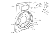
ここで、インホイールモータ型の車両駆動装置100の少なくとも一部は、ホイールW内に収容されている。ホイールWは、A2方向側が開放された略円筒形状を有している。ホイールW内には、ナックルNおよびボールジョイントJtが配置されている。ナックルNは、ホイールWを含む車輪の支持、車両における車体の懸架および車輪を操舵するための部材である。ボールジョイントJtは、ナックルNに取り付けられ、車輪を操舵する際に回転中心の一端となる部材である。
Here, at least a portion of the in-wheel motor type
具体的には、インホイールモータ型の車両駆動装置100は、ハブ1と、シャフト2と、電気モータ3と、伝達機構4と、遊星歯車機構5と、収容部材6と、オイルポンプ7とを備えている。
Specifically, the in-wheel motor type
ハブ1は、シャフト2の駆動力をホイールWに伝達するように構成されている。ハブ1は、シャフト2と一体的に回転可能にシャフト2に固定されている。シャフト2は、遊星歯車機構5の駆動力をハブ1に伝えるように構成されている。シャフト2は、遊星歯車機構5を介して伝達される電気モータ3のトルクにより回転される。シャフト2内には、軽量穴2aが形成されている。軽量穴2a内には、遊星歯車機構5の一部が配置されている。遊星歯車機構5には、電気モータ3の駆動力が伝達機構4を介して伝達される。つまり、遊星歯車機構5は、伝達機構4を介して伝達される電気モータ3のトルクにより回転される。このように、ハブ1は、伝達機構4の後述するアイドラギヤ41の駆動力をホイールWに伝達している。
The hub 1 is configured to transmit the driving force of the
図2および図3に示すように、電気モータ3の回転中心軸線C1、遊星歯車機構5の回転中心軸線C2およびオイルポンプ7の回転中心軸線C3は、D方向に沿って並んで配置されている。遊星歯車機構5、オイルポンプ7および電気モータ3は、D方向の内側から外側に向かってこの順に並んでいる。ここで、電気モータ3は、X方向において遊星歯車機構5よりもX2方向側に配置されている。また、電気モータ3は、D方向において、遊星歯車機構5とは別個に配置されている。ここで、図3は、回転中心軸線C2を基準として、101-101線に沿った断面図のうち101a部分を紙面下側に配置し、101b部分を紙面上側に配置して、回転中心軸線C2において繋げた図面である。
As shown in FIGS. 2 and 3, the rotation center axis C1 of the
電気モータ3は、車両を駆動させるための駆動力を発生させるように構成されている。具体的には、電気モータ3は、インナーロータ型のモータにより構成されている。つまり、電気モータ3は、モータシャフト31と、ステータコア32およびステータコイル33を有するステータ34およびロータ35と、ドライブギヤ36(特許請求の範囲の「駆動ギヤ」の一例)とを含んでいる。
The
モータシャフト31は、A方向に沿って延びる回転中心軸線C1の回りに回転可能に構成されている。ステータ34は、回転中心軸線C1回りにモータシャフト31を回転させるように構成されている。具体的には、ステータ34は、上記ステータコア32と、上記ステータコイル33とを有している。ステータコイル33は、ステータコア32に巻き回されることにより、モータシャフト31を回転させる回転磁界を発生させるように構成されている。ドライブギヤ36は、モータシャフト31のA2方向側端部に設けられている。ドライブギヤ36は、伝達機構4の後述するアイドラギヤ41の外歯41g(図6参照)に噛み合う外歯を有している。ドライブギヤ36の直径は、伝達機構4の後述するアイドラギヤ41の直径およびドリブンギヤ42の直径よりも小さい。
The
このように、電気モータ3は、ホイールWを駆動させるための駆動力を発生させるドライブギヤ36を有し、ドライブギヤ36を駆動させている。
In this way, the
(伝達機構)
伝達機構4は、電気モータ3の駆動力を遊星歯車機構5に伝達するように構成されている。具体的には、伝達機構4は、アイドラギヤ41(特許請求の範囲の「従動ギヤ」の一例)と、ドリブンギヤ42とを含んでいる。伝達機構4は、電気モータ3と遊星歯車機構5とを接続することにより、電気モータ3の駆動力を遊星歯車機構5に伝達している。
(Transmission mechanism)
The
アイドラギヤ41は、ドライブギヤ36に噛み合うとともに、ドリブンギヤ42に噛み合う外歯41gを有するギヤ部141(図6参照)を有している。ここで、アイドラギヤ41の外歯41gには、ドライブギヤ36の駆動力が伝達されている。
The
アイドラギヤ41は、回転中心軸線C3に沿って配置されたアイドラピン41aにより収容部材6に回転可能に取り付けられている。
The
具体的には、アイドラギヤ41は、アイドラピン41aが挿通する挿通孔41bが形成された筒状部41cを有している。筒状部41cは、アイドラピン41aをA方向に貫通している。アイドラギヤ41は、ニードル軸受け41dを介してアイドラピン41aに回転可能に取り付けられている。アイドラギヤ41には、凹部41eが形成されている。凹部41eは、アイドラギヤ41の軽量化のために形成されている凹部である。凹部41eは、ホイールW側の側面をA2方向側に窪ませ、後述する収容部172(図6参照)を内部に収容するように構成されている。
Specifically, the
ドリブンギヤ42は、アイドラギヤ41の外歯41gに噛み合う外歯を有している。ドリブンギヤ42は、遊星歯車機構5に回転可能に取り付けられている。ドリブンギヤ42には、遊星歯車機構5のA2方向側の部分が圧入されるシャフト圧入孔42aが形成されている。ドリブンギヤ42は、遊星歯車機構5を介してシャフト2に駆動力を伝達している。
The driven
ここで、ドライブギヤ36、アイドラギヤ41およびドリブンギヤ42は、回転中心軸線C2の延びる方向に直交する方向(D方向)に沿って一直線上に配置されている。
Here, the drive gear 36, the
(収容部材)
図4に示すように、収容部材6は、電気モータ3、伝達機構4、遊星歯車機構5およびオイルポンプ7を収容するように構成されている。具体的には、収容部材6は、カバー61と、第1ケース62と、第2ケース63とを有している。
(accommodating member)
As shown in FIG. 4, the
カバー61、第1ケース62および第2ケース63は、A2方向側からこの順に並んで配置されている。第1ケース62および第2ケース63により、モータ収容空間64および遊星機構収容空間65が形成されている。モータ収容空間64には、電気モータ3が収容される。遊星機構収容空間65には、遊星歯車機構5が収容される。モータ収容空間64および遊星機構収容空間65は、D方向において隣り合っている。
The
カバー61および第1ケース62により、伝達機構収容空間66およびオイルポンプ収容空間67が形成されている。伝達機構収容空間66には、伝達機構4が収容される。オイルポンプ収容空間67には、オイルポンプ7が収容される。オイルポンプ収容空間67は、伝達機構収容空間66の一部である。また、カバー61には、アイドラピン41aのA2方向側の端部が挿入される凹部61a(図3参照)が形成されている。第1ケース62には、アイドラピン41aのA1方向側の端部が挿入される凹部62aが形成されている。このように、アイドラピン41aは、カバー61および第1ケース62に回転できないように取り付けられている。アイドラピン41aは、カバー61の凹部61aおよび第1ケース62の凹部62aにより挟み込むように取り付けられている。なお、アイドラピン41aは、カバー61の凹部61aおよび第1ケース62の凹部62aの各々にニードル軸受けを介して取り付けられてもよい。ここで、アイドラギヤ41とカバー61との間には、複数(3個)のスラストワッシャ142が挟み込まれるように取り付けられている。アイドラギヤ41と第1ケース62との間には、複数(3個)のスラストワッシャ142が挟み込まれるように取り付けられている。なお、挟み込む複数のスラストワッシャ142の個数は、3個に限られず、必要な枚数のスラストワッシャを用いればよい。
The
収容部材6は、下部オイルタンク68と、上部オイルタンク69とを有している。下部オイルタンク68は、オイルポンプ7により吸入されるオイルを貯留するように構成されている。下部オイルタンク68は、第2ケース63のZ2方向側に配置されている。すなわち、下部オイルタンク68は、オイルポンプ7および電気モータ3のいずれよりもZ2方向側に配置されている。上部オイルタンク69は、オイルポンプ7により吐出されたオイルを一時的に貯留するように構成されている。上部オイルタンク69は、第2ケース63のZ1方向側の凹部と第1ケース62とを合わせることにより形成されている。すなわち、上部オイルタンク69は、オイルポンプ7および電気モータ3のいずれよりもZ1方向側に配置されている。
The
(オイルポンプ)
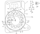
オイルポンプ7は、電気モータ3により駆動されるように構成されている。具体的には、オイルポンプ7は、ポンプハウジング71と、インナーロータ72(特許請求の範囲の「第1回転体」の一例)と、アウターロータ73(特許請求の範囲の「第2回転体」の一例)とを備えている。ここで、ポンプハウジング71、インナーロータ72およびアウターロータ73は、金属製である。
(oil pump)
The
図5および図6に示すように、ポンプハウジング71は、インナーロータ72およびアウターロータ73を収容するように構成されている。具体的には、ポンプハウジング71は、ポンププレート171(特許請求の範囲の「オイルポンプカバー」の一例)と、収容部172とを有している。
As shown in FIGS. 5 and 6, the
ポンププレート171は、薄板状に形成されている。ポンププレート171には、アイドラギヤ41を収容部材6に取り付けるためのアイドラピン41aが挿通する貫通孔271が形成されている。
ポンププレート171には、第1ポート171aおよび第2ポート171bが形成されている。第1ポート171aおよび第2ポート171bは、共に、ポンププレート171をA方向に貫通する貫通孔である。ポンププレート171には、ポンププレート171を第1ケース62に固定する締結部材が挿入される複数(2個)の締結孔171cが形成されている。複数の締結孔171cは、ポンププレート171の対角線上に配置されている。複数の締結孔171cは、ポンププレート171をA方向に貫通している。ポンププレート171は、カバー61と第1ケース62とにより挟み込まれる複数(2個)の凸部171dを有している。複数の凸部171dの各々は、ポンププレート171からA2方向に向かって突出している。複数の凸部171dは、ポンププレート171の対角線上に配置されている。
A
図6および図7に示すように、第1ポート171aおよび第2ポート171bは、共に、ポンプハウジング71内でインナーロータ72およびアウターロータ73により形成されたポンプ室S内にオイルを導くとともに、ポンプ室S外にオイルを導くように構成されている。つまり、オイルポンプ7は、インナーロータ72の回転とともにアウターロータ73が回転することにより、ポンプ室Sにオイルを吸入するとともに、ポンプ室Sからオイルを吐出するように構成されている。
As shown in FIGS. 6 and 7, the
ポンププレート171には、第1吸入側油路F1と、第1吐出側油路F2と、第2吸入側油路F3と、第2吐出側油路F4とが形成されている。第1吸入側油路F1、第1吐出側油路F2、第2吸入側油路F3および第2吐出側油路F4は、ポンププレート171のA1方向側の面をA2方向に窪ませた溝である。第1吸入側油路F1は、下部オイルタンク68から第1ポート171aにオイルを吸入するための油路である。第1吐出側油路F2は、第1ポート171aから上部オイルタンク69にオイルを吐出するための油路である。第2吸入側油路F3は、下部オイルタンク68から第2ポート171bにオイルを吸入するための油路である。第2吐出側油路F4は、第2ポート171bから上部オイルタンク69にオイルを吐出するための油路である。
The
収容部172は、ポンププレート171のA2方向側の面に設けられている。収容部172は、インナーロータ72およびアウターロータ73を収容するロータ収容空間172a(特許請求の範囲の「空間」の一例)を内部に有している。ロータ収容空間172aは、ポンププレート171のA2方向側の端面からA1方向に窪む凹形状を有している。
The
本実施形態のインナーロータ72は、アイドラギヤ41の回転に伴って一体的に回転するように構成されている。インナーロータ72は、アウターロータ73の回転中心軸線C4に対して偏心した回転中心軸線C3回りに回転することにより、アウターロータ73を回転させるように構成されている。このように、オイルポンプ7は、ドライブギヤ36またはドリブンギヤ42の回転を利用するのではなく、アイドラギヤ41の回転を利用してオイルの吸入および吐出を行うように構成されている。
The
具体的には、インナーロータ72は、複数(13枚)の外歯72aを含んでいる。また、インナーロータ72には、回転固定孔72bが形成されている。回転固定孔72bは、インナーロータ72をA方向に貫通している。
Specifically, the
回転固定孔72bには、アイドラギヤ41の筒状部41cが挿入されている。アイドラギヤ41の筒状部41cとインナーロータ72の回転固定孔72bとは、二面幅受けにより係合されている。すなわち、アイドラギヤ41の筒状部41cには、D方向において対向する一対の直線状部411が設けられている。インナーロータ72の回転固定孔72bには、D方向において対向する一対の直線状部721が設けられている。これにより、アイドラギヤ41の筒状部41cの一対の直線状部411とインナーロータ72の回転固定孔72bの一対の直線状部721とを対向させることにより、アイドラギヤ41とインナーロータ72とが係合するので、アイドラギヤ41の回転に伴ってインナーロータ72が回転する。
The
回転固定孔72bには、複数(2個)の油溝72cが形成されている。複数の油溝72cの各々は、D方向のうちの外側方向に窪んでいる。複数の油溝72cの各々は、A方向に沿って延びている。複数の油溝72cは、D方向において対向する位置に配置されている。
A plurality (two) of
また、アイドラギヤ41とインナーロータ72とは、同一回転中心軸線C3上に配置されている。このように、インナーロータ72は、アイドラギヤ41に別体として取り付けられている。
Further, the
アウターロータ73は、ポンププレート171に対して回転可能に取り付けられ、インナーロータ72と噛み合うように構成されている。具体的には、アウターロータ73は、インナーロータ72の複数の外歯72aに係合する複数(14枚)の内歯73aを有している。インナーロータ72の外歯72aは、アウターロータ73の内歯73aに、内側から係合するように、アウターロータ73の内側に配置されている。インナーロータ72の外歯72aの数は、アウターロータ73の内歯73aの数よりも1枚少ない。
The
インナーロータ72、アウターロータ73および収容部172は、アイドラギヤ41の凹部41eに収容されている。
The
インナーロータ72がR3方向またはR4方向に回転されると、アウターロータ73も回転される。回転の際、インナーロータ72とアウターロータ73との距離の小さい側では、インナーロータ72の外歯72aとアウターロータ73の内歯73aとが噛み合っている。回転の際、インナーロータ72とアウターロータ73との距離の大きい側では、外歯72aが内歯73aよりも1枚だけ少ないために、外歯72aと内歯73aとが噛み合うことなく外歯72aと内歯73aとの間に隙間(ポンプ室S)が形成されている。
When the
図7および図8に示すように、ポンプ室Sは、第1壁面S1、第2壁面S2、第3壁面S3および第4壁面S4により囲まれている。 As shown in FIGS. 7 and 8, the pump chamber S is surrounded by a first wall surface S1, a second wall surface S2, a third wall surface S3, and a fourth wall surface S4.
第1壁面S1は、オイルが吸入および吐出されるポンプ室Sを形成するためにアイドラギヤ41に設けられている。第1壁面S1は、X方向に沿って延びている。第2壁面S2は、ポンプ室Sを形成するためにポンププレート171に設けられている。第2壁面S2は、A方向において、第1壁面S1に対向している。第2壁面S2は、X方向に沿って延びている。
The first wall surface S1 is provided on the
第3壁面S3は、ポンプ室Sを形成するためにインナーロータ72の外歯72aに設けられている。第3壁面S3は、A方向に沿って延びている。第4壁面S4は、ポンプ室Sを形成するためにアウターロータ73の内歯73aに設けられている。第4壁面S4は、X方向に沿って延びている。第4壁面S4は、A方向において、第1壁面S1に対向している。
The third wall surface S3 is provided on the
インナーロータ72およびアウターロータ73(これらを合わせて、特許請求の範囲の「ポンプ回転体」の一例)は、アイドラギヤ41の第1壁面S1とポンププレート171の第2壁面S2との間に配置され、アイドラギヤ41の回転に伴って一体的に回転するように構成されている。このように、オイルポンプ7は、トロコイド式のオイルポンプにより構成されている。
The
インナーロータ72は、第1側面272と、第2側面372とを有している。第1側面272は、第1壁面S1に近接対向するA2方向側の面により構成されている。第2側面372は、第2壁面S2に近接対向するA1方向側の面により構成されている。アイドラギヤ41の回転に伴って共に回転する第1壁面S1および第1側面272の間には、第1微小隙間(図示せず)が形成されている。第2壁面S2とアイドラギヤ41の回転に伴って回転する第2側面372との間には、第2微小隙間(図示せず)が形成されている。
アイドラギヤ41の第1壁面S1とポンププレート171との間には、アイドラギヤ41の外歯41gにオイルを導く油路F5が形成されている。油路F5は、吐出圧によりポンプ室S内のオイルを外部に導く油路である。
An oil passage F5 is formed between the first wall surface S1 of the
オイルポンプ7は、アイドラギヤ41のギヤ部141を貫通するように設けられ、油路F5に連通する潤滑孔F6とを含む。潤滑孔F6は、油路F5よりも流路抵抗が小さくなるように形成されている。すなわち、潤滑孔F6の流路幅は、油路F5の流路幅よりも大きく形成されている。図示はしないが,潤滑孔F6は、ギヤ部141において等角度間隔(約90度)ごとに形成されている。なお、潤滑孔F6は、等角度間隔(約90度)ごとにギヤ部141に形成されていなくともよく、アイドラギヤ41の外歯41gを十分に潤滑可能な量のオイルを供給可能な数が形成されればよい。
The
図7に示すように、インナーロータ72およびアウターロータ73は、ポンプ室SをR3方向またはR4方向へ回転移動させてポンプ室Sを拡大・縮小させることにより、ポンプ機能を生み出している。たとえば、ポンプ室SをR3方向へ移動させて、ポンプ室Sの容積が拡大することに伴って、第1ポート171aからオイルがポンプ室Sに流れ込む。この際、ポンプ室S内の圧力は減少する(負圧になる)。また、ポンプ室Sの容積が縮小することに伴って、ポンプ室Sからオイルが第2ポート171bに流れ出る。この際、ポンプ室S内の圧力は増大する(正圧になる)。同様に、ポンプ室SをR4方向へ移動させて、ポンプ室Sの容積が拡大することに伴って、第2ポート171bからオイルがポンプ室Sに流れ込む。また、ポンプ室Sの容積が縮小することに伴って、ポンプ室Sからオイルが第1ポート171aに流れ出る。
As shown in FIG. 7, the
図9に示すように、インホイールモータ型の車両駆動装置100では、オイルポンプ7により下部オイルタンク68から吸入されたオイルは、上部オイルタンク69に供給される。上部オイルタンク69に供給されたオイルは、遊星歯車機構5および電気モータ3に自重により供給される。遊星歯車機構5および電気モータ3に供給されたオイルは、下部オイルタンク68に自重により戻る。このように、インホイールモータ型の車両駆動装置100では、オイルポンプ7によりオイルが循環されている。
As shown in FIG. 9, in the in-wheel motor type
図10および図11に示すように、オイルポンプ7は、インナーロータ72の回転方向によって、第1ポート171aおよび第2ポート171bにおいてオイルの吸入およびオイルの吐出の機能が切り替わるように構成されている。
As shown in FIGS. 10 and 11, the
具体的には、オイルポンプ7は、第1吸入側チェックバルブ74および第1吐出側チェックバルブ75と、第2吸入側チェックバルブ76および第2吐出側チェックバルブ77とを含んでいる。第1吸入側チェックバルブ74、第1吐出側チェックバルブ75、第2吸入側チェックバルブ76および第2吐出側チェックバルブ77の各々は、インナーロータ72のR3方向またはR4方向への回転に合わせて開状態と閉状態とが切り替わるように構成されている。
Specifically, the
図11の二点鎖線によって示すように、インナーロータ72のR3方向への回転により、第1吸入側チェックバルブ74および第2吐出側チェックバルブ77が開状態となり、第2吸入側チェックバルブ76および第1吐出側チェックバルブ75が閉状態となる。これにより、オイルポンプ7は、第1吸入側油路F1および第2吐出側油路F4を介して、下部オイルタンク68のオイルを上部オイルタンク69に供給するように構成されている。
As shown by the two-dot chain line in FIG. 11, the rotation of the
図示はしないが、インナーロータ72のR4方向への回転により、第2吸入側チェックバルブ76および第1吐出側チェックバルブ75が開状態となり、第1吸入側チェックバルブ74および第2吐出側チェックバルブ77が閉状態となる。これにより、オイルポンプ7は、第2吸入側油路F3および第1吐出側油路F2を介して、下部オイルタンク68のオイルを上部オイルタンク69に供給するように構成されている。
Although not shown, the rotation of the
(本実施形態の効果)
本実施形態では、以下のような効果を得ることができる。
(Effects of this embodiment)
In this embodiment, the following effects can be obtained.
本実施形態では、上記のように、インホイールモータ型の車両駆動装置100に、オイルが吸入および吐出されるポンプ室Sを形成するための第1壁面S1を有するアイドラギヤ41と、電気モータ3により駆動されるオイルポンプ7とを設ける。そして、オイルポンプ7に、ポンプ室Sの第1壁面S1に対向する第2壁面S2を有するポンププレート171と、アイドラギヤ41の第1壁面S1とポンププレート171の第2壁面S2との間の空間(ロータ収容空間172a)に配置され、アイドラギヤ41の回転に伴って一体的に回転するインナーロータ72およびアウターロータ73とを設ける。これにより、アイドラギヤ41の第1壁面S1を利用してオイルポンプ7のポンプ室Sを形成することができるので、オイルポンプ7の専用部品として第1壁面S1を形成するポンプボディを設ける必要がない。この結果、オイルポンプ7の専用部品として第1壁面S1を形成するポンプボディを設けない分だけ、オイルポンプ7の部品点数を減少させることができるとともに、インホイールモータ型の車両駆動装置100のA方向(軸方向)の寸法の増加を抑制することができる。また、アイドラギヤ41およびインナーロータ72およびアウターロータ73は一体的に回転することにより、アイドラギヤ41の回転速度とインナーロータ72およびアウターロータ73の回転速度との間に相対的な回転速度差の発生を抑制することができるので、アイドラギヤ41とインナーロータ72およびアウターロータ73との第1微小隙間に充填されているオイルのインナーロータ72およびアウターロータ73の回転に起因する変形を抑制することができる。これにより、インナーロータ72およびアウターロータ73の回転の際に第1微小隙間に充填されたオイルに生じるせん断抵抗を減少させることができる。この結果、オイルポンプ7を駆動させるためのトルクの増加を抑制することができるので、オイルポンプ7の駆動効率の悪化を抑制することができる。また、アイドラギヤ41の回転に伴って一体的に回転するインナーロータ72およびアウターロータ73を含むオイルポンプを用いることにより、電気モータ3とは別個に設けられた専用のモータにより回転するインナーロータ72およびアウターロータ73を含むオイルポンプ7を用いる場合と異なり、専用のモータのための配線などを設ける必要がない。この結果、インホイールモータ型の車両駆動装置100の大型化および複雑化を抑制することができる。
In this embodiment, as described above, the in-wheel motor type
また、本実施形態では、上記のように、インホイールモータ型の車両駆動装置100に、アイドラギヤ41の第1壁面S1とポンププレート171との間に形成され、アイドラギヤ41の外歯41gにオイルを導く油路F5を設ける。これにより、アイドラギヤ41の外歯41gにオイルを導く専用の油路を設けることなく、アイドラギヤ41の第1壁面S1とポンププレート171との間に形成される隙間としての油路F5を利用して、アイドラギヤ41の外歯41gにオイルを供給することができる。
Further, in this embodiment, as described above, in the in-wheel motor type
また、本実施形態では、上記のように、アイドラギヤ41の外歯41gに、アイドラギヤ41の外歯41gを貫通するように設けられ、油路F5に連通する潤滑孔F6を設ける。これにより、アイドラギヤ41の外歯41gの歯面(表面)により直接的にオイルを供給することができるので、アイドラギヤ41の回転をより円滑にすることができる。
Further, in this embodiment, as described above, the lubrication hole F6 is provided in the
また、本実施形態では、上記のように、オイルポンプ7を、インナーロータ72の回転とともにアウターロータ73が回転することにより、ポンプ室Sにオイルを吸入するとともに、ポンプ室Sからオイルを吐出するように構成する。これにより、アイドラギヤ41の回転を利用して回転するインナーロータ72およびアウターロータ73によりオイルの吸入および吐出を行うギヤポンプとしてオイルポンプを構成することができるので、インナーロータ72およびアウターロータ73を回転させる駆動源を別個に設ける必要がない。この結果、インホイールモータ型の車両駆動装置100の部品点数の増加および複雑化を抑制することができる。
Further, in this embodiment, as described above, the
また、本実施形態では、上記のように、オイルポンプ7を、アイドラギヤ41の回転方向の切り替えに伴って、第1ポート171aおよび第2ポート171bにおいてオイルの吸入およびオイルの吐出が切り替わるように構成する。これにより、アイドラギヤ41の回転方向にかかわらずオイルポンプ7によるオイルの吸入および吐出を行うことができるので、車両の前進または後進にかかわらずインホイールモータ型の車両駆動装置100の各構成部品にオイルを供給することができる。
Further, in this embodiment, as described above, the
また、本実施形態では、上記のように、アイドラギヤ41に、A2方向側に窪ませ、インナーロータ72およびアウターロータ73を内部に収容する凹部41eを設ける。インナーロータ72およびアウターロータ73を、ドライブギヤ36の駆動によりアイドラギヤ41と一体的に回転するように構成する。これにより、アイドラギヤ41の凹部41e内にインナーロータ72およびアウターロータ73を収容することにより、A方向におけるオイルポンプ7の大型化を抑制することができるので、インホイールモータ型の車両駆動装置100の軸方向の寸法の増加をより抑制することができる。
Further, in this embodiment, as described above, the
[変形例]
なお、今回開示された実施形態は、すべての点で例示であって制限的なものではないと考えられるべきである。本発明の範囲は、上記した実施形態の説明ではなく特許請求の範囲によって示され、さらに特許請求の範囲と均等の意味および範囲内でのすべての変更(変形例)が含まれる。
[Modified example]
Note that the embodiments disclosed this time should be considered to be illustrative in all respects and not restrictive. The scope of the present invention is indicated by the claims rather than the description of the embodiments described above, and further includes all changes (modifications) within the meaning and range equivalent to the claims.
たとえば、上記実施形態では、オイルポンプ7は、トロコイド式のオイルポンプにより構成されている例を示したが、本発明はこれに限られない。本発明では、オイルポンプは、サイクロン式のオイルポンプおよびベーン式のオイルポンプなどにより構成されてもよい。
For example, in the above embodiment, the
また、上記実施形態では、アイドラギヤ41の筒状部41cとインナーロータ72の回転固定孔72bとが、二面幅受けにより係合されている例を示したが、本発明はこれに限られない。本発明では、アイドラギヤの筒状部とインナーロータの固定孔とは、スプライン嵌合、キー溝による嵌合またピン留めなどにより取り付けられてもよい。
Further, in the above embodiment, an example was shown in which the
また、本実施形態では、金属製のインナーロータ72は、金属製のアイドラギヤ41に別体として取り付けられている例を示したが、本発明はこれに限られない。本発明では、インナーロータとアイドラギヤとを一体的に形成してもよい。
Further, in this embodiment, the metal
1 ハブ
3 電気モータ
7 オイルポンプ
36 ドライブギヤ(駆動ギヤ)
41 アイドラギヤ(従動ギヤ)
41g 外歯
41e 凹部
72 インナーロータ(ポンプ回転体、第1回転体)
73 アウターロータ(ポンプ回転体、第2回転体)
100 インホイールモータ型の車両駆動装置
141 ギヤ部
171 ポンププレート(オイルポンプカバー)
171a 第1ポート
171b 第2ポート
172a ロータ収容空間(空間)
C3 (ギヤ部の)回転中心軸線
F5 油路
F6 潤滑孔
S ポンプ室
S1 第1壁面
S2 第2壁面
W ホイール
1
41 Idler gear (driven gear)
73 Outer rotor (pump rotating body, second rotating body)
100 In-wheel motor type
171a
C3 Rotation center axis (of gear part) F5 Oil passage F6 Lubrication hole S Pump chamber S1 First wall surface S2 Second wall surface W Wheel
Claims (6)
前記駆動ギヤの駆動力が伝達されるギヤ部と、前記ギヤ部の回転中心軸線の延びる方向に直交する方向に沿って延び、オイルが吸入および吐出されるポンプ室を形成するための第1壁面とを有する従動ギヤと、
前記従動ギヤの駆動力を前記ホイールに伝達するハブと、
前記電気モータにより駆動されるオイルポンプとを備え、
前記オイルポンプは、
前記ポンプ室の前記第1壁面に対向する第2壁面を有するオイルポンプカバーと、
前記従動ギヤの前記第1壁面と前記オイルポンプカバーの前記第2壁面との間の空間に配置され、前記従動ギヤの回転に伴って一体的に回転するポンプ回転体とを含み、
前記従動ギヤは、側面を窪ませ、前記ポンプ回転体を内部に収容する凹部を含む、インホイールモータ型の車両駆動装置。 an electric motor that has a drive gear that generates a driving force for driving the wheel, and that drives the drive gear;
a gear portion to which the driving force of the drive gear is transmitted; and a first wall surface extending in a direction perpendicular to the direction in which the rotation center axis of the gear portion extends and forming a pump chamber into which oil is sucked and discharged. a driven gear having;
a hub that transmits the driving force of the driven gear to the wheel;
an oil pump driven by the electric motor,
The oil pump is
an oil pump cover having a second wall surface opposite to the first wall surface of the pump chamber;
a pump rotating body that is disposed in a space between the first wall surface of the driven gear and the second wall surface of the oil pump cover and rotates integrally with the rotation of the driven gear ;
The driven gear is an in-wheel motor type vehicle drive device, wherein the driven gear includes a recessed portion having a recessed side surface and accommodating the pump rotating body therein .
前記従動ギヤの前記第1壁面と前記オイルポンプカバーとの間に形成され、前記従動ギヤの外歯にオイルを導く油路をさらに備える、請求項1に記載のインホイールモータ型の車両駆動装置。 The gear portion of the driven gear includes external teeth that mesh with the drive gear,
The in-wheel motor type vehicle drive device according to claim 1, further comprising an oil passage formed between the first wall surface of the driven gear and the oil pump cover and guiding oil to external teeth of the driven gear. .
前記従動ギヤに取り付けられる第1回転体と、
前記オイルポンプカバーに対して回転可能に取り付けられ、前記第1回転体と噛み合う第2回転体とを有し、
前記オイルポンプは、前記第1回転体の回転とともに前記第2回転体が回転することにより、前記ポンプ室にオイルを吸入するとともに、前記ポンプ室からオイルを吐出するように構成されている、請求項1~3のいずれか1項に記載のインホイールモータ型の車両駆動装置。 The pump rotating body is
a first rotating body attached to the driven gear;
a second rotating body rotatably attached to the oil pump cover and meshing with the first rotating body;
The oil pump is configured to suck oil into the pump chamber and discharge oil from the pump chamber by rotating the second rotating body together with the rotation of the first rotating body. The in-wheel motor type vehicle drive device according to any one of items 1 to 3.
前記ポンプ室内にオイルを導くとともに、前記ポンプ室外にオイルを導く第1ポートおよび第2ポートをさらに含み、
前記オイルポンプは、前記従動ギヤの回転方向の切り替えに伴って、前記第1ポートおよび前記第2ポートにおいてオイルの吸入およびオイルの吐出が切り替わるように構成されている、請求項1~4のいずれか1項に記載のインホイールモータ型の車両駆動装置。 The oil pump cover is
further including a first port and a second port that guide oil into the pump chamber and guide oil outside the pump chamber,
5. The oil pump according to claim 1, wherein the oil pump is configured to switch between oil intake and oil discharge at the first port and the second port as the rotational direction of the driven gear is switched. The in-wheel motor type vehicle drive device according to item 1.
前記ポンプ回転体は、前記駆動ギヤの駆動により前記従動ギヤと一体的に回転するように構成されている、請求項1~5のいずれか1項に記載のインホイールモータ型の車両駆動装置。 The driven gear includes the recessed portion in which the side surface on the wheel side is recessed in a side opposite to the wheel side, and the pump rotating body is accommodated therein,
The in-wheel motor type vehicle drive device according to any one of claims 1 to 5, wherein the pump rotating body is configured to rotate integrally with the driven gear by driving the drive gear.
Priority Applications (2)
| Application Number | Priority Date | Filing Date | Title |
|---|---|---|---|
| JP2019124350A JP7367357B2 (en) | 2019-07-03 | 2019-07-03 | In-wheel motor type vehicle drive system |
| US16/906,032 US11447004B2 (en) | 2019-07-03 | 2020-06-19 | In-wheel motor vehicle drive apparatus |
Applications Claiming Priority (1)
| Application Number | Priority Date | Filing Date | Title |
|---|---|---|---|
| JP2019124350A JP7367357B2 (en) | 2019-07-03 | 2019-07-03 | In-wheel motor type vehicle drive system |
Publications (2)
| Publication Number | Publication Date |
|---|---|
| JP2021008249A JP2021008249A (en) | 2021-01-28 |
| JP7367357B2 true JP7367357B2 (en) | 2023-10-24 |
Family
ID=74065402
Family Applications (1)
| Application Number | Title | Priority Date | Filing Date |
|---|---|---|---|
| JP2019124350A Active JP7367357B2 (en) | 2019-07-03 | 2019-07-03 | In-wheel motor type vehicle drive system |
Country Status (2)
| Country | Link |
|---|---|
| US (1) | US11447004B2 (en) |
| JP (1) | JP7367357B2 (en) |
Families Citing this family (2)
| Publication number | Priority date | Publication date | Assignee | Title |
|---|---|---|---|---|
| JP2021146841A (en) * | 2020-03-18 | 2021-09-27 | 株式会社アイシン | Vehicle anti-theft device |
| US11787551B1 (en) | 2022-10-06 | 2023-10-17 | Archer Aviation, Inc. | Vertical takeoff and landing aircraft electric engine configuration |
Citations (3)
| Publication number | Priority date | Publication date | Assignee | Title |
|---|---|---|---|---|
| US20150158381A1 (en) | 2013-12-10 | 2015-06-11 | Hyundai Mobis Co., Ltd. | In-wheel assembly and vehicle with the in-wheel assembly |
| JP2017159817A (en) | 2016-03-10 | 2017-09-14 | Ntn株式会社 | In-wheel motor drive device |
| JP2018187252A (en) | 2017-05-11 | 2018-11-29 | コニカミノルタ株式会社 | Ultrasonic signal processor, ultrasonic diagnostic equipment, and ultrasonic signal processing method |
Family Cites Families (7)
| Publication number | Priority date | Publication date | Assignee | Title |
|---|---|---|---|---|
| JPS4848072U (en) * | 1971-10-07 | 1973-06-23 | ||
| JPH0487099U (en) * | 1990-12-11 | 1992-07-29 | ||
| JP4238894B2 (en) * | 2006-08-11 | 2009-03-18 | トヨタ自動車株式会社 | Motor and in-wheel motor structure using the same |
| JP4501911B2 (en) | 2006-08-11 | 2010-07-14 | トヨタ自動車株式会社 | In-wheel motor structure |
| JP4225342B2 (en) * | 2006-10-04 | 2009-02-18 | トヨタ自動車株式会社 | In-wheel motor structure |
| US9251695B2 (en) * | 2013-07-15 | 2016-02-02 | Bluepoint Alert Solutions, Llc | System and methods for providing notification in the event of a security crisis |
| JP2017065671A (en) * | 2015-09-30 | 2017-04-06 | Ntn株式会社 | In-wheel motor drive device |
-
2019
- 2019-07-03 JP JP2019124350A patent/JP7367357B2/en active Active
-
2020
- 2020-06-19 US US16/906,032 patent/US11447004B2/en active Active
Patent Citations (3)
| Publication number | Priority date | Publication date | Assignee | Title |
|---|---|---|---|---|
| US20150158381A1 (en) | 2013-12-10 | 2015-06-11 | Hyundai Mobis Co., Ltd. | In-wheel assembly and vehicle with the in-wheel assembly |
| JP2017159817A (en) | 2016-03-10 | 2017-09-14 | Ntn株式会社 | In-wheel motor drive device |
| JP2018187252A (en) | 2017-05-11 | 2018-11-29 | コニカミノルタ株式会社 | Ultrasonic signal processor, ultrasonic diagnostic equipment, and ultrasonic signal processing method |
Also Published As
| Publication number | Publication date |
|---|---|
| US20210001711A1 (en) | 2021-01-07 |
| US11447004B2 (en) | 2022-09-20 |
| JP2021008249A (en) | 2021-01-28 |
Similar Documents
| Publication | Publication Date | Title |
|---|---|---|
| JP6923466B2 (en) | Vehicle drive | |
| US7651425B2 (en) | Vehicular power transmitting apparatus | |
| JP5620826B2 (en) | Cycloid reducer and in-wheel motor drive device | |
| JP5297758B2 (en) | In-wheel motor drive device | |
| JP7367357B2 (en) | In-wheel motor type vehicle drive system | |
| JP5622033B2 (en) | Fluid pump | |
| JP2950100B2 (en) | Powertrain lubrication system for electric vehicles | |
| JP2014173587A (en) | Internal gear pump | |
| CN113544004A (en) | Left and right wheel driving device | |
| JP7124955B2 (en) | left and right wheel drive | |
| JP2019131175A (en) | In-wheel motor drive device | |
| JP2017133564A (en) | Vehicular motor drive device | |
| JP2020143689A (en) | Motor driving device for vehicle | |
| WO2020203916A1 (en) | Vehicle drive device | |
| WO2004033911A1 (en) | Integrated speed reducer and pump assembly | |
| JP4928567B2 (en) | Car supply pump | |
| US11906024B2 (en) | Vehicle drive device | |
| JP5808561B2 (en) | In-wheel motor drive device | |
| JP2016038086A (en) | Wheel driving device | |
| JP3641760B2 (en) | Fluid machine with trochoidal tooth profile | |
| JP2017024655A (en) | In-wheel motor drive device | |
| JP2021169791A (en) | Oil pump | |
| CN112020617A (en) | Gear, balancing device, and balancing device with oil pump | |
| CN219606716U (en) | Cycloidal pump for lubrication system | |
| JP7241670B2 (en) | Vehicle drive transmission device |
Legal Events
| Date | Code | Title | Description |
|---|---|---|---|
| A621 | Written request for application examination |
Free format text: JAPANESE INTERMEDIATE CODE: A621 Effective date: 20220603 |
|
| A977 | Report on retrieval |
Free format text: JAPANESE INTERMEDIATE CODE: A971007 Effective date: 20230215 |
|
| A131 | Notification of reasons for refusal |
Free format text: JAPANESE INTERMEDIATE CODE: A131 Effective date: 20230404 |
|
| A521 | Request for written amendment filed |
Free format text: JAPANESE INTERMEDIATE CODE: A523 Effective date: 20230529 |
|
| TRDD | Decision of grant or rejection written | ||
| A01 | Written decision to grant a patent or to grant a registration (utility model) |
Free format text: JAPANESE INTERMEDIATE CODE: A01 Effective date: 20230912 |
|
| A61 | First payment of annual fees (during grant procedure) |
Free format text: JAPANESE INTERMEDIATE CODE: A61 Effective date: 20230925 |
|
| R150 | Certificate of patent or registration of utility model |
Ref document number: 7367357 Country of ref document: JP Free format text: JAPANESE INTERMEDIATE CODE: R150 |