JP7367206B2 - Simulated moving bed chromatographic separation method and simulated moving bed chromatographic separation system - Google Patents
Simulated moving bed chromatographic separation method and simulated moving bed chromatographic separation system Download PDFInfo
- Publication number
- JP7367206B2 JP7367206B2 JP2022521869A JP2022521869A JP7367206B2 JP 7367206 B2 JP7367206 B2 JP 7367206B2 JP 2022521869 A JP2022521869 A JP 2022521869A JP 2022521869 A JP2022521869 A JP 2022521869A JP 7367206 B2 JP7367206 B2 JP 7367206B2
- Authority
- JP
- Japan
- Prior art keywords
- eluent
- section
- supply port
- port
- fraction
- Prior art date
- Legal status (The legal status is an assumption and is not a legal conclusion. Google has not performed a legal analysis and makes no representation as to the accuracy of the status listed.)
- Active
Links
Images


Classifications
-
- B—PERFORMING OPERATIONS; TRANSPORTING
- B01—PHYSICAL OR CHEMICAL PROCESSES OR APPARATUS IN GENERAL
- B01D—SEPARATION
- B01D15/00—Separating processes involving the treatment of liquids with solid sorbents; Apparatus therefor
- B01D15/08—Selective adsorption, e.g. chromatography
- B01D15/10—Selective adsorption, e.g. chromatography characterised by constructional or operational features
- B01D15/18—Selective adsorption, e.g. chromatography characterised by constructional or operational features relating to flow patterns
- B01D15/1814—Selective adsorption, e.g. chromatography characterised by constructional or operational features relating to flow patterns recycling of the fraction to be distributed
- B01D15/1821—Simulated moving beds
- B01D15/1828—Simulated moving beds characterized by process features
-
- B—PERFORMING OPERATIONS; TRANSPORTING
- B01—PHYSICAL OR CHEMICAL PROCESSES OR APPARATUS IN GENERAL
- B01D—SEPARATION
- B01D15/00—Separating processes involving the treatment of liquids with solid sorbents; Apparatus therefor
- B01D15/08—Selective adsorption, e.g. chromatography
- B01D15/10—Selective adsorption, e.g. chromatography characterised by constructional or operational features
- B01D15/18—Selective adsorption, e.g. chromatography characterised by constructional or operational features relating to flow patterns
- B01D15/1814—Selective adsorption, e.g. chromatography characterised by constructional or operational features relating to flow patterns recycling of the fraction to be distributed
- B01D15/1821—Simulated moving beds
- B01D15/1842—Simulated moving beds characterized by apparatus features
-
- B—PERFORMING OPERATIONS; TRANSPORTING
- B01—PHYSICAL OR CHEMICAL PROCESSES OR APPARATUS IN GENERAL
- B01D—SEPARATION
- B01D15/00—Separating processes involving the treatment of liquids with solid sorbents; Apparatus therefor
- B01D15/08—Selective adsorption, e.g. chromatography
- B01D15/10—Selective adsorption, e.g. chromatography characterised by constructional or operational features
- B01D15/18—Selective adsorption, e.g. chromatography characterised by constructional or operational features relating to flow patterns
- B01D15/1864—Selective adsorption, e.g. chromatography characterised by constructional or operational features relating to flow patterns using two or more columns
- B01D15/1871—Selective adsorption, e.g. chromatography characterised by constructional or operational features relating to flow patterns using two or more columns placed in series
-
- B—PERFORMING OPERATIONS; TRANSPORTING
- B01—PHYSICAL OR CHEMICAL PROCESSES OR APPARATUS IN GENERAL
- B01D—SEPARATION
- B01D15/00—Separating processes involving the treatment of liquids with solid sorbents; Apparatus therefor
- B01D15/08—Selective adsorption, e.g. chromatography
- B01D15/42—Selective adsorption, e.g. chromatography characterised by the development mode, e.g. by displacement or by elution
- B01D15/424—Elution mode
-
- G—PHYSICS
- G01—MEASURING; TESTING
- G01N—INVESTIGATING OR ANALYSING MATERIALS BY DETERMINING THEIR CHEMICAL OR PHYSICAL PROPERTIES
- G01N30/00—Investigating or analysing materials by separation into components using adsorption, absorption or similar phenomena or using ion-exchange, e.g. chromatography or field flow fractionation
- G01N30/02—Column chromatography
- G01N30/26—Conditioning of the fluid carrier; Flow patterns
- G01N30/38—Flow patterns
- G01N30/46—Flow patterns using more than one column
- G01N30/468—Flow patterns using more than one column involving switching between different column configurations
Description
本発明は、擬似移動層方式クロマト分離方法及び擬似移動層方式クロマト分離システムに関する。 The present invention relates to a simulated moving bed chromatographic separation method and a simulated moving bed chromatographic separation system.
擬似移動層方式によるクロマト分離では、原液中に含まれる2成分以上の成分中の特定成分に対して選択的吸着能力を有する吸着剤を充填した複数の単位充填塔(以下、単に「充填塔」とも称し、「カラム」ということもある。)を、配管を介して直列に連結し、かつ、最下流部の充填塔と最上流部の充填塔を連結して無端状とした循環系を構築する。この循環系に対して原液と溶離液を供給するとともに、循環系内の移動速度が速い画分(弱吸着性画分)と、遅い画分(強吸着性画分)と、必要により移動速度が中間的な画分(中吸着性画分)とをそれぞれ異なる位置から抜き出し、次いで、原液供給位置、溶離液供給位置、弱吸着性画分の抜き出し位置、中吸着性画分の抜き出し位置、及び強吸着性画分の抜き出し位置を、一定の位置関係に保ちながら循環系の流体循環方向に向けて移動させる。この操作を繰り返すことにより、原液供給を連続的に行うことができる移動層の処理操作を擬似的に実現する。
特許文献1には、1系列の改良された擬似移動層装置に、溶離液と原液を供給しながら中吸着性画分を抜き出す工程と、溶離液を供給しながら弱吸着性画分と強吸着性画分を抜き出す工程とを繰り返すことにより、吸着剤に対する親和力が異なる3つ以上の画分を連続的に分離する方法が開示されている。In chromatographic separation using a simulated moving bed method, a plurality of unit packed columns (hereinafter simply referred to as "packed columns") packed with an adsorbent that has the ability to selectively adsorb a specific component among two or more components contained in the stock solution are used. ) are connected in series via piping, and the most downstream packed column and the most upstream packed column are connected to construct an endless circulation system. do. In addition to supplying the stock solution and eluent to this circulation system, the fraction that moves at a fast rate (weakly adsorbent fraction), the fraction that moves slowly (strongly adsorbent fraction), and the rate of movement as necessary. The intermediate fraction (medium adsorptive fraction) is extracted from different positions, and then the stock solution supply position, the eluent supply position, the weakly adsorbent fraction extraction position, the medium adsorption fraction extraction position, The extraction position of the highly adsorbent fraction is then moved in the fluid circulation direction of the circulation system while maintaining a constant positional relationship. By repeating this operation, it is possible to simulate a moving bed processing operation in which the stock solution can be continuously supplied.
特許文献1記載の技術をはじめ従来の一般的な擬似移動層方式によるクロマト分離では、基本的に1種の溶離液を用いる。したがって、吸着剤に対する吸着性の強い成分を含む原液や、テーリング(濃度分布がブロードになる現象)を生じやすい成分を含む原液を循環系に供給する場合、これらの成分を脱着(脱離)させるために大量の溶離液を用いる必要がある。溶離液の大量使用は、抜出液の濃縮コストの上昇を招き、また、目的の精製物の、吸着剤あたりの生産量の低下にも繋がる。
In chromatographic separation using a conventional general pseudo-moving bed method, including the technique described in
他方、擬似移動層方式によるクロマト分離において、2種以上の溶離液を用いることも報告されている。例えば特許文献2には、脱着力の弱い第1溶離液と、脱着力の強い第2溶離液を用いて、これらの溶離液や原液の供給のタイミングと、弱吸着性画分、中吸着性画分及び強吸着性画分の抜き出しのタイミングとを特定の組み合わせとすることにより、少ない吸着剤量で高い分離性能を実現したことが記載されている。
On the other hand, it has also been reported that two or more types of eluents are used in chromatographic separation using a pseudo moving bed method. For example, in
擬似移動層方式のクロマト分離は、目的の精製対象物を連続的に、高純度で得ることが可能であるため、医療分野等への適用も検討されている。例えば抗体医薬の製造において、抗体を産生する培養細胞の抽出液や培養液には、目的の抗体の他、抗体が切断等されて生じた抗体として十分に機能しないフラグメントや、抗体が凝集して巨大化した凝集体が生じる。一般に、上記フラグメントは吸着剤との相互作用部位が少なく当該吸着剤に対する吸着性が弱い。逆に、凝集体は吸着剤への吸着性が強い。したがって、擬似移動層方式のクロマト分離を抗体医薬の精製に適用する場合、目的の抗体を、吸着剤に対して中間的な吸着性を示す中吸着性画分として分取する必要がある。他方、弱吸着性画分と強吸着性画分については、いずれも高い除去率で十分に取り除く必要がある。
また、このようなクロマト分離の実用化においては、必要な吸着剤量をできるだけ減らして分離処理効率を高め、低コスト化を実現することも重要である。
しかし、本発明者らが上記各特許文献に記載の技術をはじめ従来の擬似移動層方式によるクロマト分離を検討したところ、上記の目的を十分に達成することが難しいことが分かってきた。Since chromatographic separation using the pseudo moving bed method allows the target object to be purified to be obtained continuously and with high purity, its application in the medical field is also being considered. For example, in the production of antibody drugs, extracts and culture fluids from cultured cells that produce antibodies contain, in addition to the target antibody, fragments that do not function adequately as antibodies resulting from cleavage of antibodies, and antibodies that aggregate. Large aggregates form. Generally, the above-mentioned fragments have few interaction sites with the adsorbent and have weak adsorption to the adsorbent. Conversely, aggregates have strong adsorption to adsorbents. Therefore, when applying chromatographic separation using a pseudo-moving bed method to the purification of antibody drugs, it is necessary to separate the antibody of interest as a moderately adsorbent fraction that exhibits intermediate adsorbability to the adsorbent. On the other hand, both the weakly adsorbed fraction and the strongly adsorbed fraction need to be sufficiently removed at a high removal rate.
In addition, in the practical application of such chromatographic separation, it is also important to reduce the amount of adsorbent required as much as possible to increase separation processing efficiency and realize cost reduction.
However, when the present inventors investigated chromatographic separation using the conventional pseudo moving bed method, including the techniques described in the above-mentioned patent documents, it became clear that it is difficult to sufficiently achieve the above object.
そこで本発明は、擬似移動層方式を用いたクロマト分離方法であって、原液中の精製対象成分をより少ない吸着剤の使用量で、高純度に分取することを可能とするクロマト分離方法を提供することを課題とする。
また、本発明は、上記クロマト分離方法の実施に好適なクロマト分離システムを提供することを課題とする。Therefore, the present invention is a chromatographic separation method using a simulated moving bed method, which makes it possible to fractionate the components to be purified in the stock solution to high purity using a smaller amount of adsorbent. The challenge is to provide.
Another object of the present invention is to provide a chromatographic separation system suitable for carrying out the above-mentioned chromatographic separation method.
本発明者らは上記課題に鑑み鋭意検討を重ねた結果、擬似移動層方式を用いたクロマト分離方法において、溶離液を2種以上用いて、また循環系における原液供給口、強吸着性画分抜出口、中吸着性画分抜出口、及び弱吸着性画分抜出口を特定の位置関係とすることにより、上記課題の解決が可能となることを見い出した。本発明はこれらの知見に基づきさらに検討を重ね、完成されるに至ったものである。 The present inventors have conducted intensive studies in view of the above problems, and have found that in a chromatographic separation method using a pseudo moving bed method, two or more types of eluents are used, and the stock solution supply port in the circulation system and the highly adsorbent fraction are It has been found that the above problem can be solved by providing a specific positional relationship between the extraction port, the moderately adsorbable fraction extraction port, and the weakly adsorptive fraction extraction port. The present invention was completed after further studies based on these findings.
本発明の上記課題は下記手段により解決された。
〔1〕
吸着剤が充填された3つ以上の単位充填塔が配管を介して直列かつ無端状に連結された循環系を用い、該循環系を、各セクションが少なくとも1つの単位充填塔を有するように上流側から下流側に向けて円環状に連続した3つのセクション1~3に区切り、原液中に含まれる、前記吸着剤に対して弱吸着性成分と、強吸着性成分と、両成分の中間的な吸着性の中吸着性成分とを、2種以上の溶離液を用いて分離することを含む擬似移動層方式クロマト分離方法であって、
前記循環系の前記配管には、原液供給口Fと、前記2種以上の各溶離液に対応する2つ以上の溶離液供給口Dと、前記弱吸着性成分を含む弱吸着性画分の抜出口Aと、前記中吸着性成分を含む中吸着性画分の抜出口Bと、前記強吸着性成分を含む強吸着性画分の抜出口Cとが設けられ、該原液供給口F、該抜出口A、該抜出口B及び該抜出口Cの位置を下記(a)~(c)とし:
(a)前記抜出口Bを、前記原液供給口Fの、少なくとも1つのセクションを挟んで下流側に設ける;
(b)前記抜出口Cを、前記原液供給口Fを有する配管に設けるか、又は、前記抜出口Cを、前記原液供給口Fの、少なくとも1つのセクションを挟んで上流側に設ける;
(c)前記抜出口Aを、前記抜出口Bを有する配管に設けるか、又は、前記抜出口Aを、前記抜出口Bの、少なくとも1つのセクションを挟んで下流側に設ける;
前記クロマト分離方法は下記ステップ(A)及び(B)を順に繰り返すことを含む、擬似移動層方式クロマト分離方法:
[ステップ(A)]
前記原液供給口Fから原液を、前記2つ以上の溶離液供給口Dから2種以上の溶離液を、それぞれ同時に又は別々に供給し、かつ、前記抜出口Aから弱吸着性画分を、前記抜出口Bから中吸着性画分を、前記抜出口Cから強吸着性画分を、それぞれ同時に又は別々に抜き出すステップ;
[ステップ(B)]
前記ステップ(A)終了後、前記原液供給口F、前記溶離液供給口D、前記抜出口A、前記抜出口B及び前記抜出口Cを、これらの相対的な位置関係を保ったまま下流側へと移行させるステップ。
〔2〕
前記の2種以上の溶離液を用いて、前記ステップ(A)において下記サブステップ(A1-8)、(A2-8)、(A3-8)及び(A4-8)を行う、〔1〕に記載の擬似移動層方式クロマト分離方法:
<サブステップ(A1-8)>
セクション2の上流側末端を原液供給口Fとして該原液供給口Fから原液を供給し、セクション3の下流側末端を前記抜出口Aとして該抜出口Aから弱吸着性画分を抜き出す;
<サブステップ(A2-8)>
セクション1の上流側末端を溶離液供給口D-IIとして該溶離液供給口D-IIから溶離液d-IIを供給し、セクション2の上流側末端を溶離液供給口D-IIIとして該溶離液供給口D-IIIから溶離液d-IIIを供給し、前記抜出口Aから弱吸着性画分を抜き出すことにより、
セクション1を流通する溶離液の脱着力を最も強くし、
セクション2及び3を流通する溶離液の脱着力を、セクション1を流通する溶離液の脱着力よりも弱くする;
<サブステップ(A3-8)>
セクション1の上流側末端を溶離液供給口D-Iとして該溶離液供給口D-Iから溶離液d-Iを供給し、セクション1の下流側末端を前記抜出口Cとして該抜出口Cから強吸着性画分を抜き出し、セクション2の上流側末端を溶離液供給口D-IIとして該溶離液供給口D-IIから溶離液d-IIを供給し、セクション3の上流側末端を溶離液供給口D-IIIとして該溶離液供給口D-IIIから溶離液d-IIIを供給し、前記抜出口Aから弱吸着性画分を抜き出すことにより、
セクション1を流通する溶離液の脱着力を最も強くし、
セクション2を流通する溶離液の脱着力を、セクション1を流通する溶離液の脱着力よりも弱くし、
セクション3を流通する溶離液の脱着力を、セクション2を流通する溶離液の脱着力よりも弱くする;
<サブステップ(A4-8)>
前記溶離液供給口D-Iから前記溶離液d-Iを供給し、前記抜出口Cから強吸着性画分を抜き出し、前記溶離液供給口D-IIから前記溶離液d-IIを供給し、セクション2の下流側末端を前記抜出口Bとして該抜出口Bから中吸着性画分を抜き出し、セクション3の上流側末端を溶離液供給口D-IVとして該溶離液供給口D-IVから溶離液d-IVを供給し、前記抜出口Aから弱吸着性画分を抜き出すことにより、
セクション1を流通する溶離液の脱着力を最も強くし、
セクション2を流通する溶離液の脱着力を、セクション1を流通する溶離液の脱着力よりも弱くし、
セクション3を流通する溶離液の脱着力を、セクション2を流通する溶離液の脱着力よりも弱くする。
〔3〕
前記の2種以上の溶離液を用いて、前記ステップ(A)において下記サブステップ(A1-9)、(A2-9)、(A3-9)及び(A4-9)を行う、〔1〕に記載の擬似移動層方式クロマト分離方法:
<サブステップ(A1-9)>
セクション2の上流側末端を原液供給口Fとして該原液供給口Fから原液を供給し、セクション3の下流側末端を前記抜出口Aとして該抜出口Aから弱吸着性画分を抜き出す;
<サブステップ(A2-9)>
セクション1の上流側末端を溶離液供給口D-IIとして該溶離液供給口D-IIから溶離液d-IIを供給し、セクション2の上流側末端を溶離液供給口D-IIIとして該溶離液供給口D-IIIから溶離液d-IIIを供給し、前記抜出口Aから弱吸着性画分を抜き出すことにより、
セクション1を流通する溶離液の脱着力を最も強くし、
セクション2及び3を流通する溶離液の脱着力を、セクション1を流通する溶離液の脱着力よりも弱くする;
<サブステップ(A3-9)>
前記溶離液供給口D-IIから溶離液d-IIを供給し、セクション3の上流側末端を溶離液供給口D-IIIとして該溶離液供給口D-IIIから溶離液d-IIIを供給し、前記抜出口Aから弱吸着性画分を抜き出すことにより、
セクション1及び2を流通する溶離液の脱着力を最も強くし、
セクション3を流通する溶離液の脱着力を、セクション1及び2を流通する溶離液の脱着力よりも弱くする;
<サブステップ(A4-9)>
セクション1の上流側末端を溶離液供給口D-Iとして該溶離液供給口D-Iから溶離液d-Iを供給し、セクション1の下流側末端を強吸着性画分抜出口Cとして該抜出口Cから強吸着性画分を抜き出し、セクション2の上流側末端を溶離液供給口D-IIとして該溶離液供給口D-IIから溶離液d-IIを供給し、セクション2の下流側末端を中吸着性画分抜出口Bとして該抜出口Bから中吸着性画分を抜き出し、セクション3の上流側末端を溶離液供給口D-IVとして該溶離液供給口D-IVから溶離液d-IVを供給し、前記抜出口Aから弱吸着性画分を抜き出すことにより、
セクション1を流通する溶離液の脱着力を最も強くし、
セクション2を流通する溶離液の脱着力を、セクション1を流通する溶離液の脱着力よりも弱くし、
セクション3を流通する溶離液の脱着力を、セクション2を流通する溶離液の脱着力よりも弱くする。
〔4〕
前記の2種以上の溶離液を用いて、前記ステップ(A)において下記サブステップ(A1-10)、(A2-10)、(A3-10)及び(A4-10)を行う、〔1〕に記載の擬似移動層方式クロマト分離方法:
<サブステップ(A1-10)>
セクション2の上流側末端を前記原液供給口Fとして該原液供給口Fから原液を供給し、セクション3の下流側末端を前記抜出口Aとして該抜出口Aから弱吸着性画分を抜き出す;
<サブステップ(A2-10)>
セクション2の上流側末端を溶離液供給口D-IVとして、該溶離液供給口D-IVから、前記原液と脱着力が同じ又は前記原液よりも脱着力が強い溶離液d-IVを供給し、前記抜出口Aから弱吸着性画分を抜き出す;
<サブステップ(A3-10)>
セクション1の上流側末端を溶離液供給口D-Iとして該溶離液供給口D-Iから溶離液d-Iを供給し、セクション1の下流側末端を前記抜出口Cとして該抜出口Cから強吸着性画分を抜き出し、セクション2の上流側末端を溶離液供給口D-IIとして該溶離液供給口D-IIから溶離液d-IIを供給し、セクション3の上流側末端を溶離液供給口D-IIIとして該溶離液供給口D-IIIから溶離液d-IIIを供給し、前記抜出口Aから弱吸着性画分を抜き出すことにより、
セクション1を流通する溶離液の脱着力を最も強くし、
セクション2を流通する溶離液の脱着力を、セクション1を流通する溶離液の脱着力よりも弱くし、
セクション3を流通する溶離液の脱着力を、セクション2を流通する溶離液の脱着力よりも弱くする;
<サブステップ(A4-10)>
前記溶離液供給口D-Iから前記溶離液d-Iを供給し、前記抜出口Cから強吸着性画分を抜き出し、前記溶離液供給口D-IIから前記溶離液d-IIを供給し、セクション2の下流側末端を前記抜出口Bとして該抜出口Bから中吸着性画分を抜き出し、セクション3の上流側末端を溶離液供給口D-IVとして該溶離液供給口D-IVから溶離液d-IVを供給し、前記抜出口Aから弱吸着性画分を抜き出すことにより、
セクション1を流通する溶離液の脱着力を最も強くし、
セクション2を流通する溶離液の脱着力を、セクション1を流通する溶離液の脱着力よりも弱くし、
セクション3を流通する溶離液の脱着力を、セクション2を流通する溶離液の脱着力よりも弱くする。
〔5〕
吸着剤が充填された5つ以上の単位充填塔が配管を介して直列かつ無端状に連結された循環系を用い、該循環系を、各セクションが少なくとも1つの単位充填塔を有するように上流側から下流側に向けて円環状に連続した5つのセクション1~5に区切り、原液中に含まれる、前記吸着剤に対して弱吸着性成分と、強吸着性成分と、両成分の中間的な吸着性の中吸着性成分とを、2種以上の溶離液を用いて分離することを含む擬似移動層方式クロマト分離方法であって、
前記循環系の前記配管には、原液供給口Fと、前記2種以上の各溶離液に対応する2つ以上の溶離液供給口Dと、前記弱吸着性成分を含む弱吸着性画分の抜出口Aと、前記中吸着性成分を含む中吸着性画分の抜出口Bと、前記強吸着性成分を含む強吸着性画分の抜出口Cとが設けられ、該原液供給口F、該抜出口A、該抜出口B及び該抜出口Cの位置を下記(a)~(c)とし:
(a)前記抜出口Bを、前記原液供給口Fの、少なくとも1つのセクションを挟んで下流側に設ける;
(b)前記抜出口Cを、前記原液供給口Fを有する配管に設けるか、又は、前記抜出口Cを、前記原液供給口Fの、少なくとも1つのセクションを挟んで上流側に設ける;
(c)前記抜出口Aを、前記抜出口Bを有する配管に設けるか、又は、前記抜出口Aを、前記抜出口Bの、少なくとも1つのセクションを挟んで下流側に設ける;
前記クロマト分離方法は下記ステップ(A)及び(B)を順に繰り返すことを含む、擬似移動層方式クロマト分離方法:
[ステップ(A)]
前記原液供給口Fから原液を、前記2つ以上の溶離液供給口Dから2種以上の溶離液を、それぞれ同時に又は別々に供給し、かつ、前記抜出口Aから弱吸着性画分を、前記抜出口Bから中吸着性画分を、前記抜出口Cから強吸着性画分を、それぞれ同時に又は別々に抜き出すステップ;
[ステップ(B)]
前記ステップ(A)終了後、前記原液供給口F、前記溶離液供給口D、前記抜出口A、前記抜出口B及び前記抜出口Cを、これらの相対的な位置関係を保ったまま下流側へと移行させるステップ。
〔6〕
前記の2種以上の溶離液を用いて、前記ステップ(A)において下記サブステップ(A1-11)、(A2-11)及び(A3-11)を行う、〔5〕に記載の擬似移動層方式クロマト分離方法:
<サブステップ(A1-11)>
セクション3の上流側末端を前記原液供給口Fとして該原液供給口Fから原液を供給し、セクション4の上流側末端を溶離液供給口D-IIIとして該溶離液供給口D-IIIから溶離液d-IIIを供給し、セクション5の下流側末端を前記抜出口Aとして該抜出口Aから弱吸着性画分を抜き出すことにより、
セクション3を流通する溶離液の脱着力を最も強くし、
セクション4及び5を流通する溶離液の脱着力を、セクション3を流通する溶離液の脱着力よりも弱くする;
<サブステップ(A2-11)>
セクション1の上流側末端を溶離液供給口D-Iとして該溶離液供給口D-Iから溶離液d-Iを供給し、セクション1の下流側末端を前記抜出口Cとして該抜出口Cから強吸着性画分を抜き出し、セクション2の上流側末端を溶離液供給口D-IIとして該溶離液供給口D-IIから溶離液d-IIを供給し、前記溶離液供給口D-IIIから前記溶離液d-IIIを供給し、前記抜出口Aから弱吸着性画分を抜き出すことにより、
セクション1を流通する溶離液の脱着力を最も強くし、
セクション2及び3を流通する溶離液の脱着力を、セクション1を流通する溶離液の脱着力よりも弱くし、
セクション4及び5を流通する溶離液の脱着力を、セクション2及び3を流通する溶離液の脱着力よりも弱くする;
<サブステップ(A3-11)>
前記溶離液供給口D-Iから前記溶離液d-Iを供給し、前記抜出口Cから強吸着性画分を抜き出し、前記溶離液供給口D-IIから前記溶離液d-IIを供給し、セクション3の下流側末端を前記抜出口Bとして該抜出口Bから中吸着性画分を抜き出し、セクション4の上流側末端を溶離液供給口D-IVとして該溶離液供給口D-IVから溶離液d-IVを供給し、前記抜出口Aから弱吸着性画分を抜き出すことにより、
セクション1を流通する溶離液の脱着力を最も強くし、
セクション2及び3を流通する溶離液の脱着力を、セクション1を流通する溶離液の脱着力よりも弱くし、
セクション4及び5を流通する溶離液の脱着力を、セクション2及び3を流通する溶離液の脱着力よりも弱くする。
〔7〕
前記の2種以上の溶離液を用いて、前記ステップ(A)において下記サブステップ(A1-12)、(A2-12)、(A3-12)及び(A4-12)を行う、〔5〕に記載の擬似移動層方式クロマト分離方法:
<サブステップ(A1-12)>
セクション3の上流側末端を前記原液供給口Fとして該原液供給口Fから原液を供給し、セクション5の下流側末端を前記抜出口Aとして該抜出口Aから弱吸着性画分を抜き出す;
<サブステップ(A2-12)>
セクション3の上流側末端を溶離液供給口D-IVとして、該溶離液供給口D-IVから、前記原液と脱着力が同じ又は前記原液よりも脱着力が強い溶離液d-IVを供給し、前記抜出口Aから弱吸着性画分を抜き出す;
<サブステップ(A3-12)>
セクション1の上流側末端を溶離液供給口D-Iとして該溶離液供給口D-Iから溶離液d-Iを供給し、セクション1の下流側末端を前記抜出口Cとして該抜出口Cから強吸着性画分を抜き出し、セクション2の上流側末端を溶離液供給口D-IIとして該溶離液供給口D-IIから溶離液d-IIを供給し、セクション4の上流側末端を溶離液供給口D-IIIとして該溶離液供給口D-IIIから溶離液d-IIIを供給し、前記抜出口Aから弱吸着性画分を抜き出すことにより、
セクション1を流通する溶離液の脱着力を最も強くし、
セクション2及び3を流通する溶離液の脱着力を、セクション1を流通する溶離液の脱着力よりも弱くし、
セクション4及び5を流通する溶離液の脱着力を、セクション2及び3を流通する溶離液の脱着力よりも弱くする;
<サブステップ(A4-12)>
前記溶離液供給口D-Iから前記溶離液d-Iを供給し、前記抜出口Cから強吸着性画分を抜き出し、前記溶離液供給口D-IIから前記溶離液d-IIを供給し、セクション3の下流側末端を前記抜出口Bとして該抜出口Bから中吸着性画分を抜き出し、セクション4の上流側末端を溶離液供給口D-IVとして該溶離液供給口D-IVから溶離液d-IVを供給し、前記抜出口Aから弱吸着性画分を抜き出すことにより、
セクション1を流通する溶離液の脱着力を最も強くし、
セクション2及び3を流通する溶離液の脱着力を、セクション1を流通する溶離液の脱着力よりも弱くし、
セクション4及び5を流通する溶離液の脱着力を、セクション2及び3を流通する溶離液の脱着力よりも弱くする。The above-mentioned problems of the present invention were solved by the following means.
[1]
A circulation system in which three or more unit packed columns filled with adsorbent are connected in series and endlessly via piping is used, and the circulation system is connected upstream so that each section has at least one unit packed column. It is divided into three continuous
The piping of the circulation system includes a stock solution supply port F, two or more eluent supply ports D corresponding to each of the two or more eluents, and a supply port for the weakly adsorbent fraction containing the weakly adsorbable component. An extraction port A, an extraction port B for the moderately adsorptive fraction containing the medium adsorptive component, and an extraction port C for the strongly adsorptive fraction containing the strongly adsorptive component are provided, and the stock solution supply port F, The positions of the extraction port A, the extraction port B, and the extraction port C are as shown in the following (a) to (c):
(a) the extraction port B is provided downstream of the stock solution supply port F across at least one section;
(b) the extraction port C is provided in a pipe having the stock solution supply port F, or the extraction port C is provided on the upstream side of the stock solution supply port F across at least one section;
(c) the outlet A is provided in a pipe having the outlet B, or the outlet A is provided downstream of the outlet B across at least one section;
The chromatographic separation method includes repeating the following steps (A) and (B) in order, a simulated moving bed chromatographic separation method:
[Step (A)]
Supplying the stock solution from the stock solution supply port F, two or more eluents from the two or more eluent supply ports D, respectively simultaneously or separately, and supplying the weakly adsorbent fraction from the extraction port A, extracting a medium adsorptive fraction from the extraction port B and a strongly adsorptive fraction from the extraction port C, simultaneously or separately;
[Step (B)]
After the step (A) is completed, the stock solution supply port F, the eluent supply port D, the extraction port A, the extraction port B, and the extraction port C are connected to the downstream side while maintaining their relative positional relationships. Steps to transition to.
[2]
Performing the following substeps (A1-8), (A2-8), (A3-8) and (A4-8) in the step (A) using the two or more eluents described above, [1] The pseudo moving bed chromatographic separation method described in:
<Substep (A1-8)>
The upstream end of
<Substep (A2-8)>
The upstream end of
The desorption power of the eluent flowing through
making the desorption force of the eluent flowing through
<Substep (A3-8)>
The upstream end of
The desorption power of the eluent flowing through
The desorption force of the eluent flowing through
making the desorption force of the eluent flowing through
<Substep (A4-8)>
The eluent d-I is supplied from the eluent supply port DI, the strongly adsorptive fraction is extracted from the extraction port C, and the eluent d-II is supplied from the eluent supply port D-II. , the downstream end of
The desorption power of the eluent flowing through
The desorption force of the eluent flowing through
The desorption force of the eluent flowing through
[3]
Performing the following substeps (A1-9), (A2-9), (A3-9) and (A4-9) in step (A) using the two or more eluents described above, [1] The pseudo moving bed chromatographic separation method described in:
<Substep (A1-9)>
The upstream end of
<Substep (A2-9)>
The upstream end of
The desorption power of the eluent flowing through
making the desorption force of the eluent flowing through
<Substep (A3-9)>
The eluent d-II is supplied from the eluent supply port D-II, and the eluent d-III is supplied from the eluent supply port D-III by using the upstream end of
The desorption power of the eluent flowing through
making the desorption force of the eluent flowing through
<Substep (A4-9)>
The upstream end of
The desorption power of the eluent flowing through
The desorption force of the eluent flowing through
The desorption force of the eluent flowing through
[4]
Performing the following substeps (A1-10), (A2-10), (A3-10) and (A4-10) in step (A) using the two or more eluents described above, [1] The pseudo moving bed chromatographic separation method described in:
<Substep (A1-10)>
The upstream end of
<Substep (A2-10)>
The upstream end of
<Substep (A3-10)>
The upstream end of
The desorption power of the eluent flowing through
The desorption force of the eluent flowing through
making the desorption force of the eluent flowing through
<Substep (A4-10)>
The eluent d-I is supplied from the eluent supply port DI, the strongly adsorptive fraction is extracted from the extraction port C, and the eluent d-II is supplied from the eluent supply port D-II. , the downstream end of
The desorption power of the eluent flowing through
The desorption force of the eluent flowing through
The desorption force of the eluent flowing through
[5]
A circulation system in which five or more unit packed columns filled with adsorbent are connected in series and endlessly via piping is used, and the circulation system is connected upstream so that each section has at least one unit packed column. It is divided into five continuous
The piping of the circulation system includes a stock solution supply port F, two or more eluent supply ports D corresponding to each of the two or more eluents, and a supply port for the weakly adsorbent fraction containing the weakly adsorbable component. An extraction port A, an extraction port B for the moderately adsorptive fraction containing the medium adsorptive component, and an extraction port C for the strongly adsorptive fraction containing the strongly adsorptive component are provided, and the stock solution supply port F, The positions of the extraction port A, the extraction port B, and the extraction port C are as shown in the following (a) to (c):
(a) the extraction port B is provided downstream of the stock solution supply port F across at least one section;
(b) the extraction port C is provided in a pipe having the stock solution supply port F, or the extraction port C is provided on the upstream side of the stock solution supply port F across at least one section;
(c) the outlet A is provided in a pipe having the outlet B, or the outlet A is provided downstream of the outlet B across at least one section;
The chromatographic separation method includes repeating the following steps (A) and (B) in order, a simulated moving bed chromatographic separation method:
[Step (A)]
Supplying the stock solution from the stock solution supply port F, two or more eluents from the two or more eluent supply ports D, respectively simultaneously or separately, and supplying the weakly adsorbent fraction from the extraction port A, extracting a medium adsorptive fraction from the extraction port B and a strongly adsorptive fraction from the extraction port C, simultaneously or separately;
[Step (B)]
After the step (A) is completed, the stock solution supply port F, the eluent supply port D, the extraction port A, the extraction port B, and the extraction port C are connected to the downstream side while maintaining their relative positional relationships. Steps to transition to.
[6]
The pseudo mobile layer according to [5], wherein the following substeps (A1-11), (A2-11) and (A3-11) are performed in the step (A) using the two or more eluents described above. Method chromatographic separation method:
<Substep (A1-11)>
The upstream end of
The desorption power of the eluent flowing through
making the desorption force of the eluent flowing through
<Substep (A2-11)>
The upstream end of
The desorption power of the eluent flowing through
The desorption force of the eluent flowing through
making the desorption force of the eluent flowing through
<Substep (A3-11)>
The eluent d-I is supplied from the eluent supply port DI, the strongly adsorptive fraction is extracted from the extraction port C, and the eluent d-II is supplied from the eluent supply port D-II. , the downstream end of
The desorption power of the eluent flowing through
The desorption force of the eluent flowing through
The desorption force of the eluent flowing through
[7]
[5] Performing the following substeps (A1-12), (A2-12), (A3-12) and (A4-12) in the step (A) using the two or more eluents described above. The pseudo moving bed chromatographic separation method described in:
<Substep (A1-12)>
The upstream end of
<Substep (A2-12)>
The upstream end of
<Substep (A3-12)>
The upstream end of
The desorption power of the eluent flowing through
The desorption force of the eluent flowing through
making the desorption force of the eluent flowing through
<Substep (A4-12)>
The eluent d-I is supplied from the eluent supply port DI, the strongly adsorptive fraction is extracted from the extraction port C, and the eluent d-II is supplied from the eluent supply port D-II. , the downstream end of
The desorption power of the eluent flowing through
The desorption force of the eluent flowing through
The desorption force of the eluent flowing through
本明細書において、「上流」、「下流」との用語は、循環系内の流体の流通方向に対して用いられる。すなわち、循環系のある部位に対して「上流側」とは、当該部位に向けて流体が流通してくる側を意味し、「下流側」とは、当該部位から流体が流れ出ていく側を意味する。
本明細書において、「強吸着性成分」とは、原液中に含まれる複数成分のうち、吸着剤に対する吸着力が強い成分を意味し、「弱吸着性成分」とは、原液中に含まれる複数成分のうち、吸着剤に対する吸着力が弱い成分を意味し、「中吸着性成分」とは、上記強吸着性成分よりも吸着剤に対する吸着性が弱いが、上記弱吸着性成分よりは吸着剤に対する吸着性が強い成分を意味する。つまり「強吸着性」、「中吸着性」及び「弱吸着性」との用語は、原液中に含まれる各成分の吸着剤に対する吸着力を比較した際の、相対的な吸着力の強さを示すものである。
上記の「強吸着性成分」、「中吸着性成分」及び「弱吸着性成分」は、それぞれ、単一成分からなってもよく、複数の成分からなってもよい。また、当該複数の成分は吸着力が同じでも異なってもよい。
原液中の各成分の、「強吸着性成分」、「中吸着性成分」及び「弱吸着性成分」へのグループ分けは、目的に応じて適宜に設定することができる。原液が4種の成分を含む場合を例にとると、吸着剤に対する吸着力が強い順に2種の成分を合わせて強吸着性成分とし、吸着剤に対する吸着力が3番目に強い成分を中吸着性成分、吸着剤に対する吸着力が最も弱い成分を弱吸着性成分として位置付けることができる。また、吸着剤に対する吸着力が最も強い成分を強吸着性成分、吸着剤に対する吸着力が2番目の成分と3番目の成分を合わせて中吸着性成分、吸着剤に対する吸着力が最も弱い成分を弱吸着性成分として位置付けることもできる。また、吸着剤に対する吸着力が最も強い成分を強吸着性成分、吸着剤に対する吸着力が2番目の成分を中吸着性成分、吸着剤に対する吸着力が3番目の成分と最も弱い成分を合わせて弱吸着性成分として位置付けることもできる。原液が5種以上の成分を含む場合にも、同様に、種々のグループ分けに基づく分離、精製をすることができる。
本発明において、溶離液の「脱着力」とは、吸着剤に吸着した成分を、当該吸着剤から脱離させる作用の強さを意味する。In this specification, the terms "upstream" and "downstream" are used with respect to the direction of fluid flow within the circulation system. In other words, the "upstream side" of a certain part of the circulatory system means the side from which fluid flows toward the part, and the "downstream side" refers to the side from which fluid flows out from the part. means.
In this specification, the term "strongly adsorbent component" refers to a component that has a strong adsorption power to the adsorbent among multiple components contained in the stock solution, and the term "weakly adsorbent component" refers to a component that has a strong adsorption power to the adsorbent among multiple components contained in the stock solution. Among multiple components, a "medium-adsorbent component" refers to a component that has a weak adsorption power to the adsorbent, and a "medium-adsorbent component" has a weaker adsorption power to the adsorbent than the above-mentioned strongly adsorbent components, but has a weaker adsorption power than the above-mentioned weakly adsorptive components. It means a component that has strong adsorption to agents. In other words, the terms "strong adsorption,""mediumadsorption," and "weak adsorption" refer to the relative strength of adsorption when comparing the adsorption power of each component contained in the stock solution to the adsorbent. This shows that.
The above-mentioned "strongly adsorbent component", "medium adsorbent component" and "weakly adsorbent component" may each be composed of a single component or a plurality of components. Further, the adsorption powers of the plurality of components may be the same or different.
The grouping of each component in the stock solution into "strongly adsorbent components,""medium adsorbent components," and "weakly adsorbent components" can be set as appropriate depending on the purpose. For example, if the stock solution contains four components, the two components with the strongest adsorption power to the adsorbent are combined to form the strongly adsorbent component, and the component with the third strongest adsorption power to the adsorbent is the medium adsorption component. The component with the weakest adsorption power to the adsorbent can be positioned as the weakly adsorptive component. In addition, the component with the strongest adsorption power to the adsorbent is the strongly adsorbent component, the component with the second and third adsorption power to the adsorbent is the medium adsorption component, and the component with the weakest adsorption power to the adsorbent is the component. It can also be positioned as a weakly adsorptive component. In addition, the component with the strongest adsorption power to the adsorbent is the strongly adsorbent component, the component with the second adsorption power to the adsorbent is the medium adsorption component, and the component with the third adsorption power to the adsorbent and the weakest component are combined. It can also be positioned as a weakly adsorptive component. Even when the stock solution contains five or more types of components, separation and purification based on various groupings can be similarly performed.
In the present invention, the "desorption power" of the eluent refers to the strength of the action of desorbing components adsorbed onto the adsorbent from the adsorbent.
本発明の擬似移動層方式クロマト分離方法によれば、吸着剤の使用量を抑えながら、原液中の精製対象成分を高純度に分取することができる。また、本発明の擬似移動層方式クロマト分離システムは、本発明の擬似移動層方式クロマト分離方法の実施に好適に用いることができる。 According to the simulated moving bed chromatographic separation method of the present invention, the component to be purified in the stock solution can be fractionated to high purity while suppressing the amount of adsorbent used. Furthermore, the simulated moving bed chromatographic separation system of the present invention can be suitably used to carry out the simulated moving bed chromatographic separation method of the present invention.
本発明の擬似移動層方式クロマト分離方法(以下、単に「本発明の方法」ともいう。)の好ましい実施形態について説明する。 A preferred embodiment of the simulated moving bed chromatographic separation method of the present invention (hereinafter also simply referred to as "the method of the present invention") will be described.
本発明の方法は、吸着剤が充填された複数の単位充填塔を、配管を介して直列かつ無端状に連結した循環系を用いて実施される。擬似移動層方式に用いられる循環系自体は公知であり、例えば、特開2009-36536号公報や特許第4606092号公報等を参照することができる。
当該循環系について図面を用いて以下に説明するが、本発明は、本発明で規定すること以外はこれらの態様に限定されるものではない。
なお、以下で言及する図面は本発明の理解を容易にするための説明図であり、各構成のサイズや相対的な大小関係は説明の便宜上大小を変えている場合があり、実際の関係をそのまま示すものではない。また、本発明で規定する事項以外はこれらの図面に示された形状、相対的な位置関係等に限定されるものでもない。
また、本発明で規定すること以外の条件、例えば、単位充填塔の容量、配管の管内断面積や長さ、循環系に供給する液の流速等は、目的に応じて適宜に設定することができる。The method of the present invention is carried out using a circulation system in which a plurality of unit packed columns filled with adsorbent are connected in series and endlessly via piping. The circulation system itself used in the pseudo moving bed method is well known, and for example, reference can be made to Japanese Patent Application Publication No. 2009-36536, Japanese Patent No. 4606092, and the like.
The circulatory system will be described below with reference to the drawings, but the present invention is not limited to these embodiments except as specified in the present invention.
Note that the drawings mentioned below are explanatory drawings to facilitate understanding of the present invention, and the sizes and relative sizes of each component may be changed for convenience of explanation, and the actual relationships may not be the same. It is not shown as is. Furthermore, other than the matters specified in the present invention, the shapes and relative positional relationships shown in these drawings are not intended to be limiting.
In addition, conditions other than those specified in the present invention, such as the capacity of the unit packed column, the internal cross-sectional area and length of the piping, and the flow rate of the liquid supplied to the circulation system, may be set as appropriate depending on the purpose. can.
本発明の方法に用いる循環系の好ましい一実施形態を図1に示す。図1に示される循環系100は、吸着剤Abが充填された単位充填塔(カラム)を4本(単位充填塔10a、10b、10c、10d)備え、各単位充填塔の出口は、隣接する単位充填塔の入口へと配管1を介して連結され、全体として各単位充填塔が直列に連結されている。
そして、最後部の単位充填塔(例えば単位充填塔10d)の出口は、最前部の単位充填塔(例えば単位充填塔10a)の入口へと配管1を介して連結され、全単位充填塔は無端状に(円環状に)連結されている。かかる構成により、循環系100内に、流体を循環させることが可能となる。単位充填塔10a~10dは、内部の形、サイズ、吸着剤の充填量が互いに同一でも異なっていてもよい。単位充填塔10a~10dは、内部の形、サイズ、吸着剤の充填量がいずれも等価なもの(好ましくは同じもの)を用いることが好ましい。A preferred embodiment of the circulatory system used in the method of the invention is shown in FIG. The
The outlet of the rearmost unit packed column (for example, unit packed
上記循環系100内には、流体を矢印方向に流通させるための循環ポンプP1を配設することができる。循環ポンプP1は定量ポンプであることが好ましい。また、循環系100内において、互いに隣接する2つの単位充填塔の間の配管1には、その下流側の単位充填塔への流体の流通を遮断可能な遮断弁R1、R2、R3、R4が設けられている。
A circulation pump P1 for circulating fluid in the direction of the arrow can be disposed within the
各遮断弁R1~R4と、その上流側に位置する各単位充填塔10a~10dの出口との間には、それぞれ、吸着剤Abに対する弱吸着性成分を多く含む画分(本明細書において「吸着剤Abに対する弱吸着性画分」又は単に「弱吸着性画分」という。)を抜き出す弱吸着性画分抜出ライン2a、2b、2c、2dが分岐配設されている。各弱吸着性画分抜出ライン2a、2b、2c、2dには、それぞれ、各弱吸着性画分抜出ラインを開閉可能な弱吸着性画分抜出弁A1、A2、A3、A4が設けられている。各弱吸着性画分抜出ライン2a、2b、2c、2dは、合流されて一つの弱吸着性画分合流管2Jにまとめられる。
A fraction (hereinafter referred to as " Weakly adsorbent
また同様に、各遮断弁R1~R4と、その上流側に位置する各単位充填塔10a~10dの出口との間には、吸着剤Abに対する中吸着性成分を多く含む画分(本明細書において「吸着剤Abに対する中吸着性画分」又は単に「中吸着性画分」という。)を抜き出す中吸着性画分抜出ライン3a、3b、3c、3dが分岐配設されている。各中吸着性画分抜出ライン3a、3b、3c、3dには、それぞれ、各中吸着性画分抜出ラインを開閉可能な中吸着性画分抜出弁B1、B2、B3、B4が設けられている。各中吸着性画分抜出ライン3a、3b、3c、3dは、合流されて一つの中吸着性画分合流管3Jにまとめられる。
Similarly, a fraction (hereinafter referred to as a Medium-adsorbent
また同様に、各遮断弁R1~R4と、その上流側に位置する各単位充填塔10a~10dの出口との間には、吸着剤Abに対する強吸着性成分を多く含む画分(本明細書において「吸着剤Abに対する強吸着性画分」又は単に「強吸着性画分」という。)を抜き出す強吸着性画分抜出ライン4a、4b、4c、4dが分岐配設されている。各強吸着性画分抜出ライン4a、4b、4c、4dには、それぞれ、各強吸着性画分抜出ラインを開閉可能な強吸着性画分抜出弁C1、C2、C3、C4が設けられている。各強吸着性画分抜出ライン4a、4b、4c、4dは、合流されて一つの強吸着性画分合流管4Jにまとめられる。
Similarly, a fraction (hereinafter referred to as Strongly adsorbent
後述するステップ(A)の中で、弱吸着性画分抜出弁A1、A2、A3、A4のいずれかが開弁された状態となる。当該開弁された弱吸着性画分抜出弁が設置された弱吸着性画分抜出ラインと、配管1との連結部位が、後述するステップ(A)における弱吸着性画分の抜出口Aとなる。
また、後述するステップ(A)の中で、中吸着性画分抜出弁B1、B2、B3、B4のいずれかが開弁された状態となる。当該開弁された中吸着性画分抜出弁が設置された中吸着性画分抜出ラインと、配管1との連結部位が、後述するステップ(A)における中吸着性画分の抜出口Bとなる。
また、後述するステップ(A)の中で、強吸着性画分抜出弁C1、C2、C3、C4のいずれかが開弁された状態となる。当該開弁された強吸着性画分抜出弁が設置された強吸着性画分抜出ラインと、配管1との連結部位が、後述するステップ(A)における強吸着性画分の抜出口Cとなる。In step (A), which will be described later, one of the weakly adsorbent fraction extraction valves A1, A2, A3, and A4 is opened. The connection site between the weakly adsorptive fraction extraction line in which the opened weakly adsorptive fraction extraction valve is installed and
Further, in step (A) described later, one of the medium adsorbent fraction extraction valves B1, B2, B3, and B4 is opened. The connecting portion between the medium adsorptive fraction extraction line in which the opened medium adsorptive fraction extraction valve is installed and
Further, in step (A) described later, one of the strongly adsorbent fraction extraction valves C1, C2, C3, and C4 is opened. The connection site between the strongly adsorptive fraction extraction line in which the opened strongly adsorptive fraction extraction valve is installed and
循環系100には、循環系100の圧力が上昇し過ぎるのを防ぐために、適当な部位に図示していない安全弁(又はリリーフ弁)を設けることができる。また、隣接する2つの単位充填塔の間には、逆流防止用の逆止弁T1、T2、T3、T4を設けることが好ましい。
In order to prevent the pressure of the
循環系100内は、図1に示されるように、原液タンク6に収容された原液7が供給可能な構成となっている。また、循環系100内は、2種以上の溶離液が供給可能な構成となっている。図1では、一例として、4種の溶離液を供給する形態を示した。
原液7は、供給流量を制御可能な原液供給ポンプP2により、原液供給ライン11を介して供給される。原液供給ポンプP2は定量ポンプであることが好ましい。原液供給ライン11は、図1に示すように4本の原液供給分岐ライン11a、11b、11c、11dに分岐され、各原液供給分岐ライン11a、11b、11c、11dを介して、原液を、それぞれ各単位充填塔10a、10b、10c、10dの入り口へと供給可能な構成となっている。各原液供給分岐ライン11a、11b、11c、11dには、開閉可能な原液供給弁F1、F2、F3、F4が設けられ、開弁された原液供給弁を有する原液供給分岐ラインを通って、その下流に連結する単位充填塔へと原液が供給される。
後述するステップ(A)の中で、上記原液供給弁F1、F2、F3、F4のいずれかが開弁された状態となる。当該開弁された原液供給弁が設置された原液供給分岐ラインと、配管1との連結部位が、後述するステップ(A)における原液供給口Fとなる。As shown in FIG. 1, the inside of the
The
In step (A), which will be described later, one of the stock solution supply valves F1, F2, F3, and F4 is opened. The connecting portion between the stock solution supply branch line in which the opened stock solution supply valve is installed and the
図1は、脱着力の異なる4種の溶離液を供給する形態を示す。溶離液タンク8aに収容された溶離液9aは、供給流量を制御可能な溶離液供給ポンプP3により溶離液供給ライン12へと供給される。溶離液タンク8bに収容された溶離液9bは、供給流量を制御可能な溶離液供給ポンプP4により溶離液供給ライン13へと供給される。溶離液タンク8cに収容された溶離液9cは、供給流量を制御可能な溶離液供給ポンプP5により溶離液供給ライン14へと供給される。さらに、溶離液タンク8dに収容された溶離液9dは、供給流量を制御可能な溶離液供給ポンプP6により溶離液供給ライン15へと供給される。
溶離液供給ポンプP3~P6は定量ポンプであることが好ましい。溶離液供給ライン12は、図1に示すように4本の溶離液供給分岐ライン12a、12b、12c、12dに分岐され、各溶離液供給分岐ライン12a、12b、12c、12dを介して、溶離液を、各単位充填塔10a、10b、10c、10dの入り口へと供給可能な構成となっている。各溶離液供給分岐ライン12a、12b、12c、12dには、開閉可能な溶離液供給弁E1a、E2a、E3a、E4aが設けられ、開弁された溶離液供給弁を有する溶離液供給分岐ラインを通って、その下流に連結する単位充填塔へと溶離液が供給される。
同様に、溶離液供給ライン13は4本の溶離液供給分岐ライン13a、13b、13c、13dに分岐され、溶離液供給ライン14は4本の溶離液供給分岐ライン14a、14b、14c、14dに分岐され、溶離液供給ライン15は4本の溶離液供給分岐ライン15a、15b、15c、15dに分岐され、各溶離液を、各単位充填塔10a、10b、10c、10dの入り口へと供給可能な構成となっている。
溶離液供給分岐ライン13a、13b、13c、13dには、それぞれ、開閉可能な溶離液供給弁E1b、E2b、E3b、E4bが設けられ、溶離液供給分岐ライン14a、14b、14c、14dには、それぞれ、開閉可能な溶離液供給弁E1c、E2c、E3c、E4cが設けられ、溶離液供給分岐ライン15a、15b、15c、15dには、それぞれ、開閉可能な溶離液供給弁E1d、E2d、E3d、E4dが設けられている。
後述するステップ(A)の中で、開弁された溶離液供給弁が設置された溶離液供給分岐ラインと、配管1との連結部位が、溶離液供給口Dとなる。本発明の方法では、溶離液を2種以上用いるため、後述するステップ(A)の中で、開弁される溶離液供給弁は複数ある。したがって、後述するステップ(A)の中で、溶離液供給口Dは、使用する溶離液の種類に応じた数(2つ以上)存在することになる。FIG. 1 shows a configuration in which four types of eluents having different desorption powers are supplied. The
Preferably, the eluent supply pumps P3 to P6 are metering pumps. The
Similarly, the
The eluent
In step (A), which will be described later, the eluent supply port D is the connecting portion between the eluent supply branch line in which the opened eluent supply valve is installed and the
続いて、上記循環系により本発明の方法を実施する際の、循環系の作動について説明するが、本発明は、本発明で規定すること以外は、これらの実施態様に限定されるものではない。
本発明の方法において、循環系は、原液供給口Fと、弱吸着性画分の抜出口Aと、中吸着性画分の抜出口Bと、強吸着性画分の抜出口Cの位置を、下記(a)~(c)を満たす関係とする。すなわち、後述するステップ(A)及び(B)の繰り返しにおいて、原液供給口Fと、弱吸着性画分の抜出口Aと、中吸着性画分の抜出口Bと、強吸着性画分の抜出口Cとの、互いの相対的な位置関係が、当該(a)~(c)を常に満たしている。Next, the operation of the circulatory system when carrying out the method of the present invention using the above-mentioned circulatory system will be explained, but the present invention is not limited to these embodiments except as specified in the present invention. .
In the method of the present invention, the circulation system controls the positions of the stock solution supply port F, the extraction port A for the weakly adsorptive fraction, the extraction port B for the medium adsorptive fraction, and the extraction port C for the strongly adsorptive fraction. , the relationships satisfy the following (a) to (c). That is, in repeating steps (A) and (B) described later, the stock solution supply port F, the extraction port A for the weakly adsorptive fraction, the extraction port B for the medium adsorptive fraction, and the extraction port B for the strongly adsorptive fraction are connected. The relative positional relationship with the extraction port C always satisfies (a) to (c).
(a)中吸着性画分抜出口Bを、原液供給口Fの、少なくとも1つの単位充填塔(少なくとも1つのセクション)を挟んで下流側に設ける。 (a) A middle adsorptive fraction extraction port B is provided on the downstream side of the raw solution supply port F with at least one unit packed column (at least one section) interposed therebetween.
(b)強吸着性画分抜出口Cを、原液供給口Fを有する配管に設けるか、又は、強吸着性画分抜出口Cを、原液供給口Fの、少なくとも1つの単位充填塔(少なくとも1つのセクション)を挟んで上流側に設ける。
ここで、「強吸着性画分抜出口Cを、原液供給口Fを有する配管に設ける」とは、強吸着性画分抜出口Cと、原液供給口Fとの間に、単位充填塔が配されていないことを意味する。
また、「強吸着性画分抜出口Cを、原液供給口Fを有する配管に設ける」場合、強吸着性画分抜出口Cの方が、原液供給口Fよりも、同じ配管の上流側に設ける。このことは、同じ配管に設けられた抜出口と供給口との関係のすべてに当てはまる。つまり、循環系において、ある抜出口と供給口が同じ配管に設けられている場合(単位充填塔を挟まずに抜出口と供給口が設けられている場合)、抜出口の方を、供給口よりも、同じ配管の上流側に配置する。これは、供給した液がその下流の単位充填塔に届く前に、当該液が抜出口から抜き出されてしまうことを防ぐためである。
上記(b)は、強吸着性画分抜出口Cを、原液供給口Fの、少なくとも1つの単位充填塔(少なくとも1つのセクション)を挟んで上流側に設ける形態であることが好ましい。(b) A strongly adsorptive fraction extraction port C is provided in a pipe having a raw solution supply port F, or a strongly adsorptive fraction withdrawal port C is provided in at least one unit packed column (at least one section) on the upstream side.
Here, "a strongly adsorptive fraction extraction port C is provided in a pipe having a stock solution supply port F" means that a unit packed column is provided between the strongly adsorptive fraction removal port C and the stock solution supply port F. This means that it is not assigned.
In addition, when "strongly adsorptive fraction extraction port C is provided in a pipe that has stock solution supply port F", strongly adsorptive fraction removal port C is located upstream of the same pipe rather than stock solution supply port F. establish. This applies to all relationships between outlet ports and supply ports provided in the same pipe. In other words, in a circulation system, if a certain extraction port and a supply port are provided in the same piping (in a case where the withdrawal port and the supply port are provided without a unit packed column in between), the withdrawal port is connected to the supply port. Place it on the upstream side of the same piping. This is to prevent the supplied liquid from being extracted from the extraction port before it reaches the downstream unit packed tower.
In (b) above, it is preferable that the strongly adsorbent fraction extraction port C is provided upstream of the raw solution supply port F with at least one unit packed column (at least one section) interposed therebetween.
(c)弱吸着性画分抜出口Aを、中吸着性画分抜出口Bを有する配管に設けるか、又は、弱吸着性画分抜出口Aを、中吸着性画分抜出口Bの、少なくとも1つの単位充填塔(少なくとも1つのセクション)を挟んで下流側に設ける。
ここで、「弱吸着性画分抜出口Aを、中吸着性画分抜出口Bを有する配管に設ける」とは、弱吸着性画分抜出口Aと、中吸着性画分抜出口Bとの間に、単位充填塔が配されていないことを意味する。
上記(c)は、弱吸着性画分抜出口Aを、中吸着性画分抜出口Bの、少なくとも1つの単位充填塔(少なくとも1つのセクション)を挟んで下流側に設ける形態であることが好ましい。(c) A weakly adsorbent fraction outlet A is provided in a pipe having a medium adsorbent fraction outlet B, or a weakly adsorbent fraction outlet A is provided in a pipe having a medium adsorbent fraction outlet B. At least one unit packed column (at least one section) is provided on the downstream side.
Here, "providing a weakly adsorptive fraction outlet A in a pipe that has a moderately adsorptive fraction outlet B" means that the weakly adsorptive fraction outlet A and the moderately adsorptive fraction outlet B are connected to each other. This means that no unit packed tower is placed between them.
In the above (c), the weakly adsorptive fraction extraction port A may be provided downstream of the medium adsorptive fraction extraction port B with at least one unit packed column (at least one section) in between. preferable.
本発明の方法では、上記循環系を用いて、下記ステップ(A)及び(B)を順に繰り返す。 In the method of the present invention, the following steps (A) and (B) are repeated in order using the above-mentioned circulatory system.
[ステップ(A)]
原液供給口Fから原液を、2つ以上の溶離液供給口Dから2種以上の溶離液を、それぞれ同時に又は別々に供給し、かつ、弱吸着性画分抜出口Aから弱吸着性画分を、中吸着性画分抜出口Bから中吸着性画分を、強吸着性画分抜出口Cから強吸着性画分を、それぞれ同時に又は別々に抜き出すステップ。
ここで、ステップ(A)において、原液供給口Fから供給される原液の量と、溶離液供給口Dから供給される溶離液の量との合計と、弱吸着性画分抜出口Aから抜き出される弱吸着性画分の量と、中吸着性画分抜出口Bから抜き出される中吸着性画分の量と、強吸着性画分抜出口Cから抜き出される強吸着性画分Cの量との合計とは、一致する。すなわち、循環系内に液が供給されている状態においては、それと同じ量だけ、循環系内から液が抜き出される。
より詳細に説明すると、ある供給口(X)から液が供給され、その下流側のある抜出口(Y)から液が抜き出される場合において、Xよりも下流側でYよりも上流側から液が供給されていない場合、Yから抜き出される液の量は、Xから供給される液の量と同じである。また、Xよりも下流側でYよりも上流側から液が供給されている場合には、Yから抜き出される液の量は、Xから供給される液の量と、Xよりも下流側でYよりも上流側から供給されている液の量との合計と同じである。例えば図2のサブステップ(A1-1)において、溶離液供給口D1から供給する溶離液の供給量と、強吸着性画分抜出口Cから抜き出す強吸着性画分の抜出量は同じである。また、同じくサブステップ(A1-1)において、溶離液供給口D2から供給する溶離液の供給量と原液供給口Fから供給する原液の供給量との合計は、弱吸着性画分抜出口Aから抜き出す弱吸着性画分の量と同じである。
また、上記の「同時に又は別々に供給」するとは、時間的な差を設けず(供給するタイミングをずらさず)に供給するか、又は、時間的な差を設けて(供給するタイミングをずらして)供給することを意味する。ただし、一のステップ(A)内において、同じ配管に2種以上の液を供給する2つ以上の供給口が配される場合(配管に2つ以上の供給口が単位充填塔を挟まずに配され、当該2つ以上の各供給口から異なる液を供給する場合)には、当該2種以上の液の供給は同時には行わない。すなわち、一のステップ(A)の中で、当該2種以上の液の供給を異なるサブステップとして行う。同様に、一のステップ(A)内において、同じ配管に2種以上の画分を抜き出す2つ以上の抜出口が配される場合(配管に2つ以上の抜出口が単位充填塔を挟まずに配され、当該2つ以上の各抜出口から異なる画分を抜き出す場合)には、当該2種以上の画分の抜き出しは同時には行わない。すなわち、一のステップ(A)の中で、当該2種以上の画分の抜き出しを異なるサブステップとして行う。[Step (A)]
A stock solution is supplied from the stock solution supply port F, two or more eluents are supplied from two or more eluent supply ports D, respectively, simultaneously or separately, and a weakly adsorptive fraction is supplied from the weakly adsorbent fraction extraction port A. A step of simultaneously or separately extracting the medium adsorptive fraction from the medium adsorptive fraction extraction port B and the strongly adsorptive fraction from the strongly adsorptive fraction extraction port C.
Here, in step (A), the total amount of the stock solution supplied from the stock solution supply port F, the amount of the eluent supplied from the eluent supply port D, and the amount of the weakly adsorbent fraction extracted from the weakly adsorbent fraction extraction port A is calculated. The amount of the weakly adsorptive fraction taken out, the amount of the medium adsorptive fraction extracted from the medium adsorptive fraction extraction port B, and the amount of the strongly adsorptive fraction C extracted from the strongly adsorptive fraction extraction port C. The amount and the sum match. That is, when liquid is being supplied into the circulation system, the same amount of liquid is extracted from the circulation system.
To explain in more detail, when liquid is supplied from a certain supply port (X) and liquid is extracted from a certain discharge port (Y) on the downstream side, the liquid is is not supplied, the amount of liquid withdrawn from Y is the same as the amount of liquid supplied from X. In addition, if liquid is supplied downstream from X and upstream from Y, the amount of liquid extracted from Y is the amount of liquid supplied from X and the amount downstream from X. This is the same as the total amount of liquid supplied from the upstream side of Y. For example, in the sub-step (A1-1) of FIG. 2, the amount of eluent supplied from the eluent supply port D1 and the amount of strongly adsorptive fraction extracted from the strongly adsorptive fraction extraction port C are the same. be. Also, in the same substep (A1-1), the total amount of the eluent supplied from the eluent supply port D2 and the supply amount of the stock solution supplied from the stock solution supply port F is equal to The amount of weakly adsorbent fraction extracted from
In addition, the above-mentioned "supplying at the same time or separately" refers to supplying without a time difference (without shifting the supply timing) or with a time difference (with a shift in the supply timing). ) means to supply. However, if two or more supply ports supplying two or more types of liquids are arranged in the same pipe in one step (A) (two or more supply ports in the pipe do not sandwich a unit packed column) (in the case where different liquids are supplied from each of the two or more supply ports), the two or more types of liquids are not supplied at the same time. That is, in one step (A), the two or more types of liquids are supplied as different substeps. Similarly, in one step (A), if two or more extraction ports for extracting two or more types of fractions are arranged in the same piping (two or more extraction ports in the piping do not sandwich a unit packed column) (in the case where different fractions are extracted from each of the two or more extraction ports), the two or more fractions are not extracted at the same time. That is, in one step (A), the two or more fractions are extracted as different substeps.
[ステップ(B)]
前記ステップ(A)終了後、原液供給口F、溶離液供給口D、弱吸着性画分抜出口A、中吸着性画分抜出口B及び強吸着性画分抜出口Cを、これらの相対的な位置関係を保ったまま下流側へと移行させるステップ。
この下流側への移行は、原液供給口F、溶離液供給口D、弱吸着性画分抜出口A、中吸着性画分抜出口B及び強吸着性画分抜出口Cを、これらの相対的な位置関係を保ったまま、単位充填塔1個分だけ下流側へと移行させることを意味する。
例えば、ステップ(A)において、原液供給弁F1が設置された原液供給分岐ラインと配管1との連結部位が原液供給口Fであった場合、ステップ(B)により、この原液供給口Fは、原液供給弁F2が設置された原液供給分岐ラインと配管1との連結部位へと移行することになる。このことは、前記溶離液供給口D、弱吸着性画分抜出口A、中吸着性画分抜出口B及び強吸着性画分抜出口Cについても同様である。また、上記の各供給口及び抜出口の、単位充填塔1個分の下流側への移行は、循環系に配した各種ポンプや各種弁の開閉を調節することにより行うことができる。
ステップ(B)の実施により、続くステップ(A)(ステップ(A2)と称す。)において、当該ステップ(B)の直前のステップ(A)(ステップ(A1)と称す。)において各単位充填塔に対して行ったのと同じように、液の供給及び抜き出しを、ステップ(A1)よりも一つ分だけ下流側の各単位充填塔に対して行うことになる。[Step (B)]
After completing step (A), the stock solution supply port F, the eluent supply port D, the weakly adsorbent fraction extraction port A, the medium adsorption fraction extraction port B, and the strongly adsorptive fraction extraction port C are connected to each other. The step of moving downstream while maintaining the same positional relationship.
This transition to the downstream side involves connecting the stock solution supply port F, eluent supply port D, weakly adsorbent fraction withdrawal port A, medium adsorption fraction withdrawal port B, and strongly adsorptive fraction withdrawal port C to their relative positions. This means moving downstream by one unit packed column while maintaining the same positional relationship.
For example, in step (A), if the connecting portion between the stock solution supply branch line in which the stock solution supply valve F1 is installed and
By implementing step (B), in the following step (A) (referred to as step (A2)), each unit packed column in step (A) (referred to as step (A1)) immediately before the step (B) In the same manner as in step (A1), the liquid is supplied and withdrawn to each unit packed column one column downstream from step (A1).
上記ステップ(A)は、複数のサブステップで構成されていることが好ましい。この場合において、原液供給口Fからの原液の供給、2つ以上の溶離液供給口Dからの2種以上の各溶離液の供給、弱吸着性画分抜出口Aからの弱吸着性画分の抜き出し、中吸着性画分抜出口Bからの中吸着性画分の抜き出し、強吸着性画分抜出口Cからの強吸着性画分の抜き出しを、どのサブステップにおいて行うかは、本発明の効果を損なわない範囲で、目的に応じて適宜に設定することができる。
なかでも本発明の方法では、上記ステップ(A)は、原液を供給するサブステップと、原液を供給しないサブステップとを含むことが好ましい。すなわち、ステップ(A)の中に、原液を供給する時間と、原液を供給しない時間があることが好ましい。It is preferable that step (A) is comprised of a plurality of substeps. In this case, the stock solution is supplied from the stock solution supply port F, two or more eluents are supplied from two or more eluent supply ports D, and the weakly adsorptive fraction is supplied from the weakly adsorptive fraction extraction port A. In the present invention, it is determined in which substeps the extraction of the medium adsorptive fraction from the medium adsorptive fraction extraction port B, and the extraction of the strongly adsorptive fraction from the strongly adsorptive fraction extraction port C is carried out. It can be set as appropriate depending on the purpose as long as the effect is not impaired.
In particular, in the method of the present invention, step (A) preferably includes a substep of supplying the stock solution and a substep of not supplying the stock solution. That is, it is preferable that step (A) includes a time when the stock solution is supplied and a time when the stock solution is not supplied.
ステップ(A)において、2種以上の溶離液が供給される。これら2種以上の溶離液のうち脱着力が最も強い溶離液の供給口を、強吸着性画分抜出口Cに対し、単位充填塔を挟んで上流側の配管に設けることが好ましい。残りの溶離液の供給口ないし原液供給口については、脱着力が最も強い溶離液の供給口と同じ配管に設けるか、又は、脱着力が最も強い溶離液の供給口よりも、単位充填塔を挟んでさらに上流側に設けることが好ましい。「脱着力が最も強い溶離液の供給口と同じ配管に設けるか、又は、脱着力が最も強い溶離液の供給口よりも、単位充填塔を挟んでさらに上流側に設ける」とは、最も強い溶離液の供給口が設けられた配管を始点として上流側へ進み、強吸着性画分抜出口Cが設けられた配管に到達するまでの間のいずれかの配管に、最も強い溶離液以外の溶離液の供給口ないし原液供給口を設けることを意味する(換言すれば、強吸着性画分抜出口Cが設けられた配管を始点として下流側へ進み、最も強い溶離液の供給口が設けられた配管に到達するまでの間のいずれかの配管に、最も強い溶離液以外の溶離液の供給口ないし原液供給口を設けることを意味する。さらに別の言い方をすれば、最も強い溶離液の供給口と強吸着性画分抜出口Cとの間に単位充填塔が2つ以上設けられている場合において、当該2つ以上の単位充填塔同士を繋ぐ配管には、溶離液の供給口ないし原液供給口を設けないことを意味する)。この場合において、最も強い溶離液以外の溶離液が2種以上ある場合には、これらに対応する2つ以上の供給口は、それらの一部が同じ配管に設けられていてもよいし、それぞれが単位充填塔を挟んだ別々の配管に設けられていてもよい。また、最も強い溶離液以外の溶離液の供給口と原液供給口とが、同じ配管に設けられていてもよい。
なお、脱着力が最も強い溶離液以外の溶離液の供給口のうち1つの供給口を、脱着力が最も強い溶離液の供給口と同じ配管に設けることは、本発明の好ましい一実施形態である。In step (A), two or more eluents are supplied. It is preferable to provide a supply port for the eluent having the strongest desorption power among these two or more types of eluents in a pipe upstream of the strongly adsorptive fraction extraction port C across the unit packed column. The remaining eluent supply port or stock solution supply port should be installed in the same piping as the eluent supply port with the strongest desorption power, or should be installed in a unit packed column rather than the supply port of the eluent with the strongest desorption power. It is preferable to provide it on the further upstream side. "It should be installed in the same piping as the supply port of the eluent with the strongest desorption power, or it should be installed further upstream across the unit packed column from the supply port of the eluent with the strongest desorption power." Starting from the piping provided with the eluent supply port, proceed upstream until reaching the piping provided with the strongly adsorbent fraction extraction port C. This means providing an eluent supply port or stock solution supply port (in other words, starting from the piping provided with the strongly adsorbent fraction extraction port C and proceeding downstream, a supply port for the strongest eluent is provided). This means that a supply port for an eluent other than the strongest eluent or a stock solution supply port is provided in any of the pipes before reaching the pipe where the eluent is When two or more unit packed towers are provided between the supply port of C and the highly adsorbent fraction extraction port C, the piping connecting the two or more unit packed towers is provided with an eluent supply port. (This means that there is no stock solution supply port). In this case, if there are two or more types of eluent other than the strongest eluent, the two or more corresponding supply ports may be partially provided in the same piping, or each may be provided in separate pipes sandwiching the unit packed column. Furthermore, a supply port for an eluent other than the strongest eluent and a stock solution supply port may be provided in the same piping.
Note that in a preferred embodiment of the present invention, one of the supply ports for the eluent other than the eluent having the strongest desorption power is provided in the same pipe as the supply port for the eluent having the strongest desorption power. be.
ステップ(A)において、2種以上の溶離液のうち脱着力が最も強い溶離液を供給している間は、その下流から、脱着力が最も強い溶離液の供給量と同じ量の強吸着性画分を抜き出す形態とすることが好ましい。この場合、脱着力が最も強い溶離液の供給口からその下流の強吸着性画分抜出口までの間には、少なくとも1つの単位充填塔が配され、また、当該間には他の供給口は存在しない形態とすることが好ましい。 In step (A), while the eluent with the strongest desorption power among the two or more eluents is being supplied, from downstream thereof, the same amount of the eluent with the strongest desorption power as the eluent with the strongest adsorption power is supplied. It is preferable to use a form in which a fraction is extracted. In this case, at least one unit packed column is arranged between the supply port of the eluent having the strongest desorption power and the downstream outlet of the highly adsorbent fraction, and other supply ports It is preferable that the form does not exist.
ステップ(A)において、2種以上の溶離液のうち脱着力が2番目に強い溶離液を供給しながら、その下流から、脱着力が2番目に強い溶離液の供給量と同じ量の中吸着性画分を抜き出す時間帯(サブステップ)を設けることが好ましい。この場合、脱着力が2番目に強い溶離液の供給口からその下流の中吸着性画分抜出口までの間には、少なくとも1つの単位充填塔(好ましくは複数の単位充填塔)が配される。また、脱着力が2番目に強い溶離液の供給口が設けられた配管からその下流側の中吸着性画分抜出口が設けられた配管までの間に他の供給口が存在していたとしても、上記の中吸着性画分を抜き出す時間帯には当該他の供給口からは液を供給しない。 In step (A), while supplying the eluent with the second strongest desorption power among the two or more eluents, from downstream thereof, medium adsorption is performed in an amount equal to the supply amount of the eluent with the second strongest desorption power. It is preferable to provide a time period (substep) for extracting the sex fraction. In this case, at least one unit packed column (preferably a plurality of unit packed columns) is disposed between the supply port of the eluent having the second strongest desorption force and the downstream outlet of the medium adsorptive fraction. Ru. In addition, it is assumed that there is another supply port between the pipe where the eluent supply port with the second strongest desorption force is installed and the downstream pipe where the medium adsorption fraction extraction port is installed. Also, no liquid is supplied from the other supply ports during the time period when the medium adsorptive fraction is extracted.
ステップ(A)を実施している間は、常に弱吸着性画分を抜き出していることが好ましい。したがって、ステップ(A)を複数のサブステップで構成する場合にも、当該複数のサブステップにおいて、弱吸着性画分は常に抜き出されていることが好ましい。 While carrying out step (A), it is preferable to always extract the weakly adsorbent fraction. Therefore, even when step (A) is composed of a plurality of substeps, it is preferable that the weakly adsorbed fraction is always extracted in the plurality of substeps.
本発明の方法には、互いに脱着力が異なる3種以上の溶離液を用いることが好ましく、互いに脱着力が異なる4種以上の溶離液を用いることがより好ましく、互いに脱着力が異なる4~6種の溶離液を用いることがさらに好ましく、互いに脱着力が異なる4種又は5種の溶離液を用いることが特に好ましい。
溶離液の種類は特に制限されず、吸着剤の種類や原液中の成分の種類との関係により適宜に設定される。例えば、吸着剤としてイオン交換樹脂を用いる場合、溶離液の塩濃度を変えることにより、脱着力が異なる複数の溶離液を調製することができる。例えば、陽イオン交換樹脂を用いる場合には、NaCl濃度を変えた複数の溶離液を、2種以上の溶離液として用いることができる。In the method of the present invention, it is preferable to use three or more types of eluents having mutually different desorption powers, more preferably four or more types of eluents having mutually different desorption powers, and four to six types having mutually different desorption powers. It is more preferable to use different types of eluents, and it is particularly preferable to use four or five types of eluents having different desorption powers.
The type of eluent is not particularly limited, and is appropriately set depending on the type of adsorbent and the type of components in the stock solution. For example, when using an ion exchange resin as an adsorbent, a plurality of eluents having different desorption powers can be prepared by changing the salt concentration of the eluent. For example, when using a cation exchange resin, a plurality of eluents with different NaCl concentrations can be used as two or more eluents.
上記ステップ(A)におけるサブステップの組み合わせの好ましい実施形態について、以下に説明する。これらの形態の実施は、図1のシステムを用いたり、図1のシステムに準じる、目的の形態を実施可能なシステムを用いたりして行うことができる。また、下記の実施形態は本発明の一例であり、例えば、相対的な脱着力の観点から、下記の溶離液d-1として位置付けられる2種以上の溶離液を用意し、溶離液d-1を供給するサブステップ間において、使用する溶離液d-1の種類を変えることもできる。このことは、溶離液d-II~d-Vについても同様である。
すなわち本発明では、ある実施形態において「溶離液d-1」という場合、この実施形態において、異なるサブステップで「溶離液d-1」を使用する場合には、異なるサブステップで使用する「溶離液d-1」は互いに同じでもよいし、異なってもよい。このことは、溶離液d-II~d-Vについても同様である。A preferred embodiment of the combination of substeps in step (A) above will be described below. These embodiments can be implemented using the system shown in FIG. 1 or a system similar to the system shown in FIG. 1 that can implement the desired embodiments. Furthermore, the following embodiment is an example of the present invention, and for example, from the viewpoint of relative desorption power, two or more eluents positioned as the eluent d-1 below are prepared, and the eluent d-1 is It is also possible to change the type of eluent d-1 used between the substeps of supplying the eluent d-1. This also applies to the eluents d-II to dV.
That is, in the present invention, when "eluent d-1" is used in a certain embodiment, when "eluent d-1" is used in different substeps in this embodiment, "eluent d-1" used in different substeps is referred to as "eluent d-1". "liquid d-1" may be the same or different. This also applies to the eluents d-II to dV.
-実施形態1-
実施形態1では、単位充填塔を4つ以上有する循環系を用いる。そして、この循環系を、各セクションが少なくとも1つの単位充填塔を有するように上流側から下流側に向けて円環状に連続した4つのセクション1~4に区切ったものを想定する。また、溶離液として、脱着力の異なる4種の溶離液d-I~d-IVを用いる。
この実施形態1においては、ステップ(A)において下記サブステップ(A1-1)、(A2-1)及び(A3-1)を行う。
本発明において、「ステップ(A)においてサブステップX、Y及びZを行う」とは、ステップ(A)が、サブステップX、Y及びZを含んでいることを意味し、サブステップX,Y及びZを行う順序は、本発明の効果を損なわない範囲で適宜に設定することができる。また、ステップ(A)は、サブステップX、Y及びZ以外の、他のサブステップを含んでもよい。
「ステップ(A)においてサブステップX、Y及びZを行う」形態として、典型的には、ステップ(A)としてサブステップX、Y及びZを順に行う形態が挙げられるが、本発明はこの形態に限定されない。すなわち、「ステップ(A)においてサブステップX、Y及びZを行う」とは、サブステップXの直後にサブステップYを行い、サブステップYの直後にサブステップZを行い、サブステップZの直後にステップ(B)を行い、ステップ(B)の直後にサブステップXを行う形態に限られない。例えば、上記の他のサブステップを含む形態では、サブステップXの前(ステップ(B)とサブステップXとの間)、サブステップXとYとの間、サブステップYとZとの間、サブステップZとステップ(B)との間の少なくとも1つにおいて、本発明の効果を損なわない範囲で、他のサブステップ(サブステップX、Y及びZ以外のサブステップ)を組み込むことができる。供給流量、流速、溶離液強さ等の調整により、サブステップX,Y及びZ以外の付加的なサブステップを込み込んでも目的の効果が得られる場合があり、このことは本明細書に接した当業者であれば容易に理解することである。-Embodiment 1-
In
In this first embodiment, the following substeps (A1-1), (A2-1), and (A3-1) are performed in step (A).
In the present invention, "performing substeps X, Y, and Z in step (A)" means that step (A) includes substeps X, Y, and Z; The order in which steps and Z are performed can be appropriately set within a range that does not impair the effects of the present invention. Further, step (A) may include substeps other than substeps X, Y, and Z.
The form of "performing substeps X, Y, and Z in step (A)" typically includes a form in which substeps X, Y, and Z are performed in order as step (A), but the present invention does not apply to this form. but not limited to. That is, "perform substeps X, Y, and Z in step (A)" means to perform substep Y immediately after substep X, perform substep Z immediately after substep Y, and perform substep Z immediately after substep Z. The present invention is not limited to a form in which step (B) is performed before the step (B) is performed and substep X is performed immediately after the step (B). For example, in a form including the other substeps described above, before substep X (between step (B) and substep X), between substeps X and Y, between substeps Y and Z, Other substeps (substeps other than substeps X, Y, and Z) can be incorporated in at least one of substeps Z and step (B) to the extent that the effects of the present invention are not impaired. By adjusting the supply flow rate, flow rate, eluent strength, etc., the desired effect may be obtained even by including additional substeps other than substeps X, Y, and Z, and this is not related to this specification. This will be easily understood by those skilled in the art.
<サブステップ(A1-1)>
セクション1の上流側末端を溶離液供給口D-Iとして該溶離液供給口D-Iから溶離液d-Iを供給し、セクション1の下流側末端を強吸着性画分抜出口Cとして該抜出口Cから強吸着性画分を抜き出し、セクション2の上流側末端を溶離液供給口D-IIとして該溶離液供給口D-IIから溶離液d-IIを供給し、セクション3の上流側末端を原液供給口Fとして該原液供給口Fから原液を供給し、セクション4の下流側末端を弱吸着性画分抜出口Aとして該抜出口Aから弱吸着性画分を抜き出すことにより、
セクション1を流通する溶離液の脱着力を最も強くし、
セクション2を流通する溶離液の脱着力を、セクション1を流通する溶離液の脱着力よりも弱くし、
セクション3及び4を流通する溶離液の脱着力を、セクション2を流通する溶離液の脱着力よりも弱くする。
サブステップ(A1-1)では、上記の各液の供給と、各画分の抜き出しが、連続的に行われる(すなわち、サブステップ(A1-1)では常に、上記の各液の供給と、各画分の抜き出しのすべてが絶え間なく行われている。)。このことは、以降に説明する各サブステップにおいても同様である。
また、本発明ないし本明細書において、各サブステップで説明する溶離液の脱着力の強弱の説明は、当該サブステップ内における溶離液の脱着力の強弱であり、異なるサブステップにおける溶離液の脱着力の強弱を説明するものではない。例えば、ステップ(A)を構成する一のサブステップにおいてセクション1を流通する溶離液の脱着力を最も強くすることが説明され、当該ステップ(A)を構成する別のサブステップにおいてもセクション1を流通する溶離液の脱着力を最も強くすることが説明されている場合、当該一のサブステップにおいてセクション1を流通する溶離液の脱着力と、当該別のサブステップにおいてセクション1を流通する溶離液の脱着力とは、同じでもよいし、異なっていてもよい。<Substep (A1-1)>
The upstream end of
The desorption power of the eluent flowing through
The desorption force of the eluent flowing through
The desorption force of the eluent flowing through
In the substep (A1-1), the supply of each of the above liquids and the extraction of each fraction are performed continuously (that is, in the substep (A1-1), the supply of each of the above liquids and the extraction of each of the above liquids are always performed, All extractions of each fraction are carried out continuously). This also applies to each substep described below.
Furthermore, in the present invention and this specification, the strength of the desorption force of the eluent explained in each substep refers to the strength of the desorption force of the eluent within the substep, and the desorption force of the eluent in different substeps. It does not explain the strength or weakness of power. For example, it is explained that in one substep of step (A), the desorption force of the eluent flowing through
<サブステップ(A2-1)>
前記溶離液供給口D-Iから前記溶離液d-Iを供給し、前記抜出口Cから強吸着性画分を抜き出し、前記溶離液供給口D-IIから前記溶離液d-IIを供給し、セクション3の上流側末端を溶離液供給口D-IIIとして該溶離液供給口D-IIIから溶離液d-IIIを供給し、前記抜出口Aから弱吸着性画分を抜き出すことにより、
セクション1を流通する溶離液の脱着力を最も強くし、
セクション2を流通する溶離液の脱着力を、セクション1を流通する溶離液の脱着力よりも弱くし、
セクション3及び4を流通する溶離液の脱着力を、セクション2を流通する溶離液の脱着力よりも弱くする。
このサブステップ(A2-1)における溶離液供給口D-IIIは、上記サブステップ(A1-1)における原液供給口Fと同じ配管に設けられている。<Substep (A2-1)>
The eluent d-I is supplied from the eluent supply port DI, the highly adsorbent fraction is extracted from the extraction port C, and the eluent d-II is supplied from the eluent supply port D-II. , by setting the upstream end of
The desorption power of the eluent flowing through
The desorption force of the eluent flowing through
The desorption force of the eluent flowing through
The eluent supply port D-III in this substep (A2-1) is provided in the same pipe as the stock solution supply port F in the above substep (A1-1).
<サブステップ(A3-1)>
前記溶離液供給口D-Iから前記溶離液d-Iを供給し、前記抜出口Cから強吸着性画分を抜き出し、前記溶離液供給口D-IIから前記溶離液d-IIを供給し、セクション3の下流側末端を中吸着性画分抜出口Bとして該抜出口Bから中吸着性画分を抜き出し、セクション4の上流側末端を溶離液供給口D-IVとして該溶離液供給口D-IVから溶離液d-IVを供給し、前記抜出口Aから弱吸着性画分を抜き出すことにより、
セクション1を流通する溶離液の脱着力を最も強くし、
セクション2及び3を流通する溶離液の脱着力を、セクション1を流通する溶離液の脱着力よりも弱くし、
セクション4を流通する溶離液の脱着力を、セクション2及び3を流通する溶離液の脱着力よりも弱くする。<Substep (A3-1)>
The eluent d-I is supplied from the eluent supply port DI, the strongly adsorptive fraction is extracted from the extraction port C, and the eluent d-II is supplied from the eluent supply port D-II. , the downstream end of
The desorption power of the eluent flowing through
The desorption force of the eluent flowing through
The desorption force of the eluent flowing through
上記サブステップ(A2-1)において、セクション3及び4を流通する溶離液の脱着力は、上記サブステップ(A3-1)において、セクション4を流通する溶離液の脱着力と同じであることも好ましい。
In the above substep (A2-1), the desorption force of the eluent flowing through
上記サブステップ(A1-1)の一例として、下記サブステップ(A1-1ex)を実施するサブステップが挙げられるが、上記サブステップ(A1-1)はサブステップ(A1-1ex)に限定されるものではない。
<サブステップ(A1-1ex)>
セクション1の上流側末端を溶離液供給口D1として、該溶離液供給口D1から4種の溶離液のうち脱着力が最も強い溶離液d1を供給し、
セクション1の下流側末端を強吸着性画分抜出口Cとして、該抜出口Cから強吸着性画分を抜き出し、
セクション2の上流側末端を溶離液供給口D2として、該溶離液供給口D2から4種の溶離液のうち脱着力が2番目に強い溶離液d2を供給し、
セクション3の上流側末端を原液供給口Fとして、該原液供給口Fから原液を供給し、
セクション4の下流側末端を弱吸着性画分抜出口Aとして、該抜出口Aから弱吸着性画分を抜き出す。An example of the above substep (A1-1) is a substep of implementing the following substep (A1-1ex), but the above substep (A1-1) is limited to the substep (A1-1ex). It's not a thing.
<Substep (A1-1ex)>
The upstream end of
The downstream end of
The upstream end of
The upstream end of
The downstream end of
上記サブステップ(A2-1)の一例として、下記サブステップ(A2-1ex)を実施するサブステップが挙げられるが、上記サブステップ(A2-1)はサブステップ(A2-1ex)に限定されるものではない。
<サブステップ(A2-1ex)>
前記溶離液供給口D1から前記溶離液d1を供給し、
前記強吸着性画分抜出口Cから強吸着性画分を抜き出し、
前記溶離液供給口D2から前記溶離液d2を供給し、
セクション3の上流側末端を溶離液供給口D3として、該溶離液供給口D3から4種の溶離液のうち脱着力が最も弱い溶離液d3を供給し、
前記弱吸着性画分抜出口Aから弱吸着性画分を抜き出す。
このサブステップ(A2-1ex)における溶離液供給口D3は、上記サブステップ(A1-1)における原液供給口Fと同じ配管に設けられている。An example of the above substep (A2-1) is a substep of implementing the following substep (A2-1ex), but the above substep (A2-1) is limited to the substep (A2-1ex). It's not a thing.
<Substep (A2-1ex)>
supplying the eluent d1 from the eluent supply port D1;
extracting the strongly adsorbent fraction from the strongly adsorbent fraction extraction port C;
supplying the eluent d2 from the eluent supply port D2;
The upstream end of
The weakly adsorptive fraction is extracted from the weakly adsorptive fraction extraction port A.
The eluent supply port D3 in this substep (A2-1ex) is provided in the same piping as the stock solution supply port F in the above substep (A1-1).
上記サブステップ(A3-1)の一例として、下記サブステップ(A3-1ex)を実施するサブステップが挙げられるが、上記サブステップ(A3-1)はサブステップ(A3-1ex)に限定されるものではない。
<サブステップ(A3-1ex)>
前記溶離液供給口D1から溶離液d1を供給し、
前記強吸着性画分抜出口Cから強吸着性画分を抜き出し、
前記溶離液供給口D2から前記溶離液d2を供給し、
セクション3の下流側末端を中吸着性画分抜出口Bとして、該抜出口Bから中吸着性画分を抜き出し、
セクション4の上流側末端を溶離液供給口D4として、該溶離液供給口D4から4種の溶離液のうち脱着力が3番目に強い溶離液d4を供給し、
前記弱吸着性画分抜出口Aから弱吸着性画分を抜き出す。An example of the above substep (A3-1) is a substep of implementing the following substep (A3-1ex), but the above substep (A3-1) is limited to the substep (A3-1ex). It's not a thing.
<Substep (A3-1ex)>
Supplying the eluent d1 from the eluent supply port D1,
extracting the strongly adsorbent fraction from the strongly adsorbent fraction extraction port C;
supplying the eluent d2 from the eluent supply port D2;
The downstream end of
The upstream end of
The weakly adsorptive fraction is extracted from the weakly adsorptive fraction extraction port A.
各セクションが単位充填塔を一つ有する場合を例にとり、上記ステップ(A)が上記サブステップ(A1-1ex)、(A2-1ex)及び(A3-1ex)を順に行う場合のフロー図を図2に示す。図2中、四角の囲いは単位充填塔1つ分を示し、当該囲いの中の数字は単位充填塔の番号(左から順に付番した)を示す。
上記サブステップ(A1-1ex)、(A2-1ex)及び(A3-1ex)を順に行うステップ(A)が終了後、ステップ(B)により、原液供給口F、前記溶離液供給口D、前記弱吸着性画分抜出口A、前記中吸着性画分抜出口B及び前記強吸着性画分抜出口Cを、これらの相対的な位置関係を保ったまま下流側へと移行させ、次いで上記サブステップ(A1-1ex)、(A2-1ex)及び(A3-1ex)を順に行った場合のフロー図を図3に示す。図2に示す、各セクションに配される単位充填塔が、図3では1つずつ下流側のものへとシフトする。この場合、図2に示すステップ(A)からスタートし、次いでステップ(B)を行うことを1セットとし、これを4セット行うことにより、再び図2に示す形態に戻ることになる。Taking the case where each section has one unit packed column as an example, the flow diagram when the above step (A) sequentially performs the above substeps (A1-1ex), (A2-1ex) and (A3-1ex) is shown below. Shown in 2. In FIG. 2, a square box indicates one packed unit column, and the numbers inside the box indicate the numbers of the packed unit columns (numbered sequentially from the left).
After the step (A) of performing the above substeps (A1-1ex), (A2-1ex) and (A3-1ex) in order is completed, in step (B), the stock solution supply port F, the eluent supply port D, the The weakly adsorptive fraction extraction port A, the medium adsorptive fraction extraction port B, and the strongly adsorptive fraction extraction port C are moved to the downstream side while maintaining their relative positional relationship, and then the above-mentioned FIG. 3 shows a flow diagram when substeps (A1-1ex), (A2-1ex), and (A3-1ex) are performed in order. The unit packed columns arranged in each section shown in FIG. 2 are shifted one by one to the downstream side in FIG. 3. In this case, starting from step (A) shown in FIG. 2 and then performing step (B) is one set, and by performing this four sets, the process returns to the form shown in FIG. 2 again.
-実施形態2-
実施形態2も実施形態1と同様に、単位充填塔を4つ以上有する循環系を用いる。そして、この循環系を、各セクションが少なくとも1つの単位充填塔を有するように上流側から下流側に向けて円環状に連続した4つのセクション1~4に区切ったものを想定する。また、溶離液として、脱着力の異なる4種の溶離液d-I~d-IVを用いる。
この実施形態2においては、ステップ(A)として下記サブステップ(A1-2)、(A2-2)及び(A3-2)を順に行う。-Embodiment 2-
Similarly to
In this second embodiment, the following substeps (A1-2), (A2-2), and (A3-2) are performed in order as step (A).
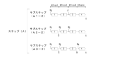
<サブステップ(A1-2)>
セクション1の上流側末端を溶離液供給口D-IIとして該溶離液供給口D-IIから溶離液d-IIを供給し、セクション3の上流側末端を原液供給口Fとして該原液供給口Fから原液を供給し、セクション4の下流側末端を弱吸着性画分抜出口Aとして該抜出口Aから弱吸着性画分を抜き出すことにより、
セクション1及び2を流通する溶離液の脱着力を最も強くし、
セクション3及び4を流通する溶離液の脱着力を、セクション1及び2を流通する溶離液の脱着力よりも弱くする。<Substep (A1-2)>
The upstream end of
The desorption power of the eluent flowing through
The desorption force of the eluent flowing through
<サブステップ(A2-2)>
セクション1の上流側末端を溶離液供給口D-Iとして該溶離液供給口D-Iから溶離液d-Iを供給し、セクション1の下流側末端を強吸着性画分抜出口Cとして該抜出口Cから強吸着性画分を抜き出し、セクション2の上流側末端を溶離液供給口D-IIとして該溶離液供給口D-IIから溶離液d-IIを供給し、セクション3の上流側末端を溶離液供給口D-IIIとして該溶離液供給口D-IIIから溶離液d-IIIを供給し、前記抜出口Aから弱吸着性画分を抜き出すことにより、
セクション1を流通する溶離液の脱着力を最も強くし、
セクション2を流通する溶離液の脱着力を、セクション1を流通する溶離液の脱着力よりも弱くし、
セクション3及び4を流通する溶離液の脱着力を、セクション2を流通する溶離液の脱着力よりも弱くする。
このサブステップ(A2-2)における溶離液供給口D-Iは、上記サブステップ(A1-2)における溶離液供給口D-IIと同じ配管に設けられている。また、溶離液供給口D-IIIは、原液供給口Fと同じ配管に設けられている。
このサブステップ(A2-2)においてセクション1を流通する溶離液の脱着力は、上記サブステップ(A1-2)においてセクション1を流通する溶離液の脱着力よりも強いことが好ましい。<Substep (A2-2)>
The upstream end of
The desorption power of the eluent flowing through
The desorption force of the eluent flowing through
The desorption force of the eluent flowing through
The eluent supply port DI in this substep (A2-2) is provided in the same pipe as the eluent supply port D-II in the substep (A1-2). Further, the eluent supply port D-III is provided in the same piping as the stock solution supply port F.
The desorption force of the eluent flowing through
<サブステップ(A3-2)>
前記溶離液供給口D-Iから前記溶離液d-Iを供給し、前記抜出口Cから強吸着性画分を抜き出し、サブステップ(A2-2)における前記溶離液供給口D-IIから前記溶離液d-IIを供給し、セクション3の下流側末端を中吸着性画分抜出口Bとして該抜出口Bから中吸着性画分を抜き出し、セクション4の上流側末端を溶離液供給口D-IVとして該溶離液供給口D-IVから溶離液d-IVを供給し、前記抜出口Aから弱吸着性画分を抜き出すことにより、
セクション1を流通する溶離液の脱着力を最も強くし、
セクション2及び3を流通する溶離液の脱着力を、セクション1を流通する溶離液の脱着力よりも弱くし、
セクション4を流通する溶離液の脱着力を、セクション2及び3を流通する溶離液の脱着力よりも弱くする。<Substep (A3-2)>
The eluent d-I is supplied from the eluent supply port DI, the strongly adsorptive fraction is extracted from the extraction port C, and the The eluent d-II is supplied, the downstream end of
The desorption power of the eluent flowing through
The desorption force of the eluent flowing through
The desorption force of the eluent flowing through
上記サブステップ(A1-2)の一例として、下記サブステップ(A1-2ex)を実施するサブステップが挙げられるが、上記サブステップ(A1-2)はサブステップ(A1-2ex)に限定されるものではない。
<サブステップ(A1-2ex)>
セクション1の上流側末端を溶離液供給口D2として、該溶離液供給口D2から4種の溶離液のうち脱着力が2番目に強い溶離液d2を供給し、
セクション3の上流側末端を原液供給口Fとして、該原液供給口Fから原液を供給し、
セクション4の下流側末端を弱吸着性画分抜出口Aとして、該抜出口Aから弱吸着性画分を抜き出す。An example of the above substep (A1-2) is a substep of implementing the following substep (A1-2ex), but the above substep (A1-2) is limited to the substep (A1-2ex). It's not a thing.
<Substep (A1-2ex)>
The upstream end of
The upstream end of
The downstream end of
上記サブステップ(A2-2)の一例として、下記サブステップ(A2-2ex)を実施するサブステップが挙げられるが、上記サブステップ(A2-2)はサブステップ(A2-2ex)に限定されるものではない。
<サブステップ(A2-2ex)>
セクション1の上流側末端を溶離液供給口D1として、該溶離液供給口D1から4種の溶離液のうち脱着力が最も強い溶離液d1を供給し、
セクション1の下流側末端を強吸着性画分抜出口Cとして、該抜出口Cから強吸着性画分を抜き出し、
セクション2の上流側末端を溶離液供給口D2として、該溶離液供給口D2から4種の溶離液のうち脱着力が2番目に強い溶離液d2を供給し、
セクション3の上流側末端を溶離液供給口D3として、該溶離液供給口D3から4種の溶離液のうち脱着力が最も弱い溶離液d3を供給し、
前記弱吸着性画分抜出口Aから弱吸着性画分を抜き出す。
このサブステップ(A2-2ex)における溶離液供給口D1は、上記サブステップ(A1-2ex)における溶離液供給口D2と同じ配管に設けられている。また、溶離液供給口D3は、上記サブステップ(A1-2ex)における原液供給口Fと同じ配管に設けられている。An example of the above substep (A2-2) is a substep of implementing the following substep (A2-2ex), but the above substep (A2-2) is limited to the substep (A2-2ex). It's not a thing.
<Substep (A2-2ex)>
The upstream end of
The downstream end of
The upstream end of
The upstream end of
The weakly adsorptive fraction is extracted from the weakly adsorptive fraction extraction port A.
The eluent supply port D1 in this substep (A2-2ex) is provided in the same pipe as the eluent supply port D2 in the above substep (A1-2ex). Further, the eluent supply port D3 is provided in the same pipe as the stock solution supply port F in the above sub-step (A1-2ex).
上記サブステップ(A3-2)の一例として、下記サブステップ(A3-2ex)を実施するサブステップが挙げられるが、上記サブステップ(A3-2)はサブステップ(A3-2ex)に限定されるものではない。
<サブステップ(A3-2ex)>
前記溶離液供給口D1から前記溶離液d1を供給し、
前記強吸着性画分抜出口Cから強吸着性画分を抜き出し、
サブステップ(A2-2ex)における前記溶離液供給口D2から前記溶離液d2を供給し、
セクション3の下流側末端を中吸着性画分抜出口Bとして、該抜出口Bから中吸着性画分を抜き出し、
セクション4の上流側末端を溶離液供給口D4として、該溶離液供給口D4から4種の溶離液のうち脱着力が3番目に強い溶離液d4を供給し、
前記弱吸着性画分抜出口Aから弱吸着性画分を抜き出す。An example of the above substep (A3-2) is a substep of implementing the following substep (A3-2ex), but the above substep (A3-2) is limited to the substep (A3-2ex). It's not a thing.
<Substep (A3-2ex)>
supplying the eluent d1 from the eluent supply port D1;
extracting the strongly adsorbent fraction from the strongly adsorbent fraction extraction port C;
Supplying the eluent d2 from the eluent supply port D2 in substep (A2-2ex),
The downstream end of
The upstream end of
The weakly adsorptive fraction is extracted from the weakly adsorptive fraction extraction port A.
各セクションが単位充填塔を一つ有する場合を例にとり、上記ステップ(A)が上記サブステップ(A1-2ex)、(A2-2ex)及び(A3-2ex)を順に行う場合のフロー図を図4に示す。図4中、四角の囲いは単位充填塔1つ分を示し、当該囲いの中の数字は単位充填塔の番号を示す。
上記サブステップ(A1-2ex)、(A2-2ex)及び(A3-2ex)を順に行うステップ(A)が終了後、ステップ(B)により、原液供給口F、溶離液供給口D、弱吸着性画分抜出口A、中吸着性画分抜出口B及び強吸着性画分抜出口Cを、これらの相対的な位置関係を保ったまま下流側へと移行させ、次いで上記サブステップ(A1-2ex)、(A2-2ex)及び(A3-2ex)を順に行った場合のフロー図を図5に示す。図4に示す、各セクションに配される単位充填塔が、図5では1つずつ下流側のものへとシフトする。この場合、図4に示すステップ(A)からスタートし、次いでステップ(B)を行うことを1セットとし、これを4セット行うことにより、再び図4に示す形態に戻ることになる。Taking the case where each section has one unit packed column as an example, the flow diagram when the above step (A) sequentially performs the above substeps (A1-2ex), (A2-2ex) and (A3-2ex) is shown below. 4. In FIG. 4, the square box indicates one packed unit column, and the number inside the box indicates the number of the packed unit column.
After completing step (A), in which the above substeps (A1-2ex), (A2-2ex), and (A3-2ex) are completed, in step (B), the stock solution supply port F, the eluent supply port D, and the weak adsorption The sexually adsorbent fraction extraction port A, the medium adsorptive fraction extraction port B, and the highly adsorptive fraction extraction port C are moved to the downstream side while maintaining their relative positional relationships, and then the above substep (A1 FIG. 5 shows a flowchart when steps (A2-2ex), (A2-2ex), and (A3-2ex) are performed in order. The unit packed columns arranged in each section shown in FIG. 4 are shifted one by one to the downstream side in FIG. In this case, starting from step (A) shown in FIG. 4 and then performing step (B) is one set, and by performing this four sets, the process returns to the form shown in FIG. 4 again.
-実施形態3-
実施形態3は、単位充填塔を5つ以上有する循環系を用いる。そして、この循環系を、各セクションが少なくとも1つの単位充填塔を有するように上流側から下流側に向けて円環状に連続した5つのセクション1~5に区切ったものを想定する。また、溶離液として、脱着力の異なる4種の溶離液d-I~d-IVを用いる。
この実施形態3においては、ステップ(A)として下記サブステップ(A1-3)、(A2-3)及び(A3-3)を順に行う。-Embodiment 3-
In this third embodiment, the following substeps (A1-3), (A2-3), and (A3-3) are performed in order as step (A).
<サブステップ(A1-3)>
セクション1の上流側末端を溶離液供給口D-IIとして該溶離液供給口D-IIから溶離液d-IIを供給し、セクション3の上流側末端を原液供給口Fとして該原液供給口Fから原液を供給し、セクション4の上流側末端を溶離液供給口D-IIIとして該溶離液供給口D-IIIから溶離液d-IIIを供給し、セクション5の下流側末端を弱吸着性画分抜出口Aとして該抜出口Aから弱吸着性画分を抜き出すことにより、
セクション1及び2を流通する溶離液の脱着力を最も強くし、
セクション3を流通する溶離液の脱着力を、セクション1及び2を流通する溶離液の脱着力と同じか又はセクション1及び2を流通する溶離液の脱着力よりも弱くし、
セクション4及び5を流通する溶離液の脱着力を、セクション3を流通する溶離液の脱着力よりも弱くする。<Substep (A1-3)>
The upstream end of
The desorption power of the eluent flowing through
The desorption force of the eluent flowing through
The desorption force of the eluent flowing through
<サブステップ(A2-3)>
セクション1の上流側末端を溶離液供給口D-Iとして該溶離液供給口D-Iから溶離液d-Iを供給し、セクション1の下流側末端を強吸着性画分抜出口Cとして該抜出口Cから強吸着性画分を抜き出し、セクション2の上流側末端を溶離液供給口D-IIとして該溶離液供給口D-IIから溶離液d-IIを供給し、前記溶離液供給口D-IIIから前記溶離液d-IIIを供給し、前記抜出口Aから弱吸着性画分を抜き出すことにより、
セクション1を流通する溶離液の脱着力を最も強くし、
セクション2及び3を流通する溶離液の脱着力を、セクション1を流通する溶離液の脱着力よりも弱くし、
セクション4及び5を流通する溶離液の脱着力を、セクション2及び3を流通する溶離液の脱着力よりも弱くする。
このサブステップ(A2-3)においてセクション1を流通する溶離液の脱着力は、上記サブステップ(A1-3)においてセクション1を流通する溶離液の脱着力よりも強いことが好ましい。
このサブステップ(A2-3)における溶離液供給口D-Iは、上記サブステップ(A1-3)における溶離液供給口D-IIと同じ配管に設けられている。<Substep (A2-3)>
The upstream end of
The desorption power of the eluent flowing through
The desorption force of the eluent flowing through
The desorption force of the eluent flowing through
The desorption force of the eluent flowing through
The eluent supply port DI in this substep (A2-3) is provided in the same pipe as the eluent supply port D-II in the above substep (A1-3).
<サブステップ(A3-3)>
前記溶離液供給口D-Iから前記溶離液d-Iを供給し、前記抜出口Cから強吸着性画分を抜き出し、サブステップ(A2-3)における前記溶離液供給口D-IIから前記溶離液d-IIを供給し、セクション4の下流側末端を中吸着性画分抜出口Bとして該抜出口Bから中吸着性画分を抜き出し、セクション5の上流側末端を溶離液供給口D-IVとして該溶離液供給口D-IVから溶離液d-IVを供給し、前記抜出口Aから弱吸着性画分を抜き出すことにより、
セクション1を流通する溶離液の脱着力を最も強くし、
セクション2、3及び4を流通する溶離液の脱着力を、セクション1を流通する溶離液の脱着力よりも弱くし、
セクション5を流通する溶離液の脱着力を、セクション2、3及び4を流通する溶離液の脱着力よりも弱くする。<Substep (A3-3)>
The eluent d-I is supplied from the eluent supply port DI, the strongly adsorptive fraction is extracted from the eluent port C, and the The eluent d-II is supplied, the downstream end of
The desorption power of the eluent flowing through
The desorption force of the eluent flowing through
The desorption force of the eluent flowing through
上記サブステップ(A1-3)の一例として、下記サブステップ(A1-3ex)を実施するサブステップが挙げられるが、上記サブステップ(A1-3)はサブステップ(A1-3ex)に限定されるものではない。
<サブステップ(A1-3ex)>
セクション1の上流側末端を溶離液供給口D2として、該溶離液供給口D2から4種の溶離液のうち脱着力が2番目に強い溶離液d2を供給し、
セクション3の上流側末端を原液供給口Fとして、該原液供給口Fから原液を供給し、
セクション4の上流側末端を溶離液供給口D3として、該溶離液供給口D3から4種の溶離液のうち脱着力が最も弱い溶離液d3を供給し、
セクション5の下流側末端を弱吸着性画分抜出口Aとして、該抜出口Aから弱吸着性画分を抜き出す。An example of the above sub-step (A1-3) is a sub-step of implementing the following sub-step (A1-3ex), but the above sub-step (A1-3) is limited to the sub-step (A1-3ex). It's not a thing.
<Substep (A1-3ex)>
The upstream end of
The upstream end of
The upstream end of
The downstream end of
上記サブステップ(A2-3)の一例として、下記サブステップ(A2-3ex)を実施するサブステップが挙げられるが、上記サブステップ(A2-3)はサブステップ(A2-3ex)に限定されるものではない。
<サブステップ(A2-3ex)>
セクション1の上流側末端を溶離液供給口D1として、該溶離液供給口D1から4種の溶離液のうち脱着力が最も強い溶離液d1を供給し、
セクション1の下流側末端を強吸着性画分抜出口Cとして、該抜出口Cから強吸着性画分を抜き出し、
セクション2の上流側末端を溶離液供給口D2として、該溶離液供給口D2から4種の溶離液のうち脱着力が2番目に強い溶離液d2を供給し、
前記溶離液供給口D3から前記溶離液d3を供給し、
前記弱吸着性画分抜出口Aから弱吸着性画分を抜き出す。
このサブステップ(A2-3ex)における溶離液供給口D1は、上記サブステップ(A1-3ex)における溶離液供給口D2と同じ配管に設けられている。An example of the above substep (A2-3) is a substep that implements the following substep (A2-3ex), but the above substep (A2-3) is limited to the substep (A2-3ex). It's not a thing.
<Substep (A2-3ex)>
The upstream end of
The downstream end of
The upstream end of
supplying the eluent d3 from the eluent supply port D3;
The weakly adsorptive fraction is extracted from the weakly adsorptive fraction extraction port A.
The eluent supply port D1 in this substep (A2-3ex) is provided in the same pipe as the eluent supply port D2 in the above substep (A1-3ex).
上記サブステップ(A3-3)の一例として、下記サブステップ(A3-3ex)を実施するサブステップが挙げられるが、上記サブステップ(A3-3)はサブステップ(A3-3ex)に限定されるものではない。
<サブステップ(A3-3ex)>
前記溶離液供給口D1から前記溶離液d1を供給し、
前記強吸着性画分抜出口Cから強吸着性画分を抜き出し、
サブステップ(A2-3ex)における前記溶離液供給口D2から前記溶離液d2を供給し、
セクション4の下流側末端を中吸着性画分抜出口Bとして、該抜出口Bから中吸着性画分を抜き出し、
セクション5の上流側末端を溶離液供給口D4として、該溶離液供給口D4から4種の溶離液のうち脱着力が3番目に強い溶離液d4を供給し、
前記弱吸着性画分抜出口Aから弱吸着性画分を抜き出す。An example of the above substep (A3-3) is a substep of implementing the following substep (A3-3ex), but the above substep (A3-3) is limited to the substep (A3-3ex). It's not a thing.
<Sub step (A3-3ex)>
Supplying the eluent d1 from the eluent supply port D1,
extracting the strongly adsorbent fraction from the strongly adsorbent fraction extraction port C;
Supplying the eluent d2 from the eluent supply port D2 in substep (A2-3ex),
The downstream end of
The upstream end of
The weakly adsorptive fraction is extracted from the weakly adsorptive fraction extraction port A.
各セクションが単位充填塔を一つ有する場合を例にとり、上記ステップ(A)が上記サブステップ(A1-3ex)、(A2-3ex)及び(A3-3ex)を順に行う場合のフロー図を図6に示す。図6中、四角の囲いは単位充填塔1つ分を示し、当該囲いの中の数字は単位充填塔の番号を示す。
上記サブステップ(A1-3ex)、(A2-3ex)及び(A3-3ex)を順に行うステップ(A)が終了後、ステップ(B)により、原液供給口F、溶離液供給口D、弱吸着性画分抜出口A、中吸着性画分抜出口B及び強吸着性画分抜出口Cを、これらの相対的な位置関係を保ったまま下流側へと移行させ、次いで上記サブステップ(A1-3ex)、(A2-3ex)及び(A3-3ex)を順に行った場合のフロー図を図7に示す。図6に示す、各セクションに配される単位充填塔が、図7では1つずつ下流側のものへとシフトする。この場合、図6に示すステップ(A)からスタートし、次いでステップ(B)を行うことを1セットとし、これを5セット行うことにより、再び図6に示す形態に戻ることになる。Taking as an example the case where each section has one unit packed column, the flow diagram when the above step (A) sequentially performs the above substeps (A1-3ex), (A2-3ex) and (A3-3ex) is shown. 6. In FIG. 6, a square box indicates one unit packed column, and the number inside the box indicates the number of the unit packed column.
After completing step (A), in which the above substeps (A1-3ex), (A2-3ex), and (A3-3ex) are completed, in step (B), the stock solution supply port F, the eluent supply port D, and the weak adsorption The sexually adsorbent fraction extraction port A, the medium adsorptive fraction extraction port B, and the highly adsorptive fraction extraction port C are moved to the downstream side while maintaining their relative positional relationships, and then the above substep (A1 FIG. 7 shows a flowchart when steps (A2-3ex), (A2-3ex), and (A3-3ex) are performed in order. The unit packed columns arranged in each section shown in FIG. 6 are shifted one by one to the downstream side in FIG. 7. In this case, starting from step (A) shown in FIG. 6 and then performing step (B) is one set, and by performing this five sets, the process returns to the form shown in FIG. 6 again.
-実施形態4-
実施形態4は、単位充填塔を7つ以上有する循環系を用いる。そして、この循環系を、各セクションが少なくとも1つの単位充填塔を有するように上流側から下流側に向けて円環状に連続した5つのセクション1~5に区切ったものを想定する。また、溶離液として、脱着力の異なる5種の溶離液d-I~d-Vを用いる。
この実施形態4においては、ステップ(A)として下記サブステップ(A1-4)、(A2-4)及び(A3-4)を順に行う。-Embodiment 4-
In this fourth embodiment, the following substeps (A1-4), (A2-4), and (A3-4) are performed in order as step (A).
<サブステップ(A1-4)>
セクション1の上流側末端を溶離液供給口D-IIとして該溶離液供給口D-IIから溶離液d-IIを供給し、セクション3の上流側末端を原液供給口Fとして該原液供給口Fから原液を供給し、セクション4の上流側末端を溶離液供給口D-IIIとして該溶離液供給口D-IIIから溶離液d-IIIを供給し、セクション5の下流側末端を前記抜出口Aとして該抜出口Aから弱吸着性画分を抜き出すことにより、
セクション1及び2を流通する溶離液の脱着力を最も強くし、
セクション3を流通する溶離液の脱着力を、セクション1及び2を流通する溶離液の脱着力と同じか又はセクション1及び2を流通する溶離液の脱着力よりも弱くし、
セクション4及び5を流通する溶離液の脱着力を、セクション3を流通する溶離液の脱着力よりも弱くする。<Substep (A1-4)>
The upstream end of
The desorption power of the eluent flowing through
The desorption force of the eluent flowing through
The desorption force of the eluent flowing through
<サブステップ(A2-4)>
セクション1の上流側末端を溶離液供給口D-Iとして該溶離液供給口D-Iから溶離液d-Iを供給し、セクション1の下流側末端を強吸着性画分抜出口Cとして該抜出口Cから強吸着性画分を抜き出し、セクション2の上流側末端を溶離液供給口D-IIとして該溶離液供給口D-IIから溶離液d-IIを供給し、セクション4の上流側末端を溶離液供給口D-IVとして該溶離液供給口D-IVから溶離液d-IVを供給し、前記抜出口Aから弱吸着性画分を抜き出すことにより、
セクション1を流通する溶離液の脱着力を最も強くし、
セクション2及び3を流通する溶離液の脱着力を、セクション1を流通する溶離液の脱着力よりも弱くし、
セクション4及び5を流通する溶離液の脱着力を、セクション2及び3を流通する溶離液の脱着力よりも弱くする。
このサブステップ(A2-4)においてセクション1を流通する溶離液の脱着力は、上記サブステップ(A1-4)においてセクション1を流通する溶離液の脱着力よりも強いことが好ましい。
このサブステップ(A2-4)における溶離液供給口D-Iは、上記サブステップ(A1-4)における溶離液供給口D-IIと同じ配管に設けられている。<Substep (A2-4)>
The upstream end of
The desorption power of the eluent flowing through
The desorption force of the eluent flowing through
The desorption force of the eluent flowing through
The desorption force of the eluent flowing through
The eluent supply port DI in this substep (A2-4) is provided in the same pipe as the eluent supply port D-II in the substep (A1-4).
<サブステップ(A3-4)>
前記溶離液供給口D-Iから前記溶離液d-Iを供給し、前記抜出口Cから強吸着性画分を抜き出し、サブステップ(A2-4)における前記溶離液供給口D2から前記溶離液d2を供給し、セクション4の下流側末端を中吸着性画分抜出口Bとして該抜出口Bから中吸着性画分を抜き出し、セクション5の上流側末端を溶離液供給口D-Vとして、該溶離液供給口D-Vから溶離液d-Vを供給し、前記抜出口Aから弱吸着性画分を抜き出すことにより、
セクション1を流通する溶離液の脱着力を最も強くし、
セクション2、3及び4を流通する溶離液の脱着力を、セクション1を流通する溶離液の脱着力よりも弱くし、
セクション5を流通する溶離液の脱着力を、セクション2、3及び4を流通する溶離液の脱着力よりも弱くする。<Substep (A3-4)>
The eluent d-I is supplied from the eluent supply port DI, the strongly adsorbent fraction is extracted from the extraction port C, and the eluent is supplied from the eluent supply port D2 in substep (A2-4). d2, the downstream end of
The desorption power of the eluent flowing through
The desorption force of the eluent flowing through
The desorption force of the eluent flowing through
上記サブステップ(A1-4)の一例として、下記サブステップ(A1-4ex)を実施するサブステップが挙げられるが、上記サブステップ(A1-4)はサブステップ(A1-4ex)に限定されるものではない。
<サブステップ(A1-4ex)>
セクション1の上流側末端を溶離液供給口D2として、該溶離液供給口D2から5種の溶離液のうち脱着力が2番目に強い溶離液d2を供給し、
セクション3の上流側末端を原液供給口Fとして、該原液供給口Fから原液を供給し、
セクション4の上流側末端を溶離液供給口D3として、該溶離液供給口D3から5種の溶離液のうち脱着力が最も弱い溶離液d3を供給し、
セクション5の下流側末端を弱吸着性画分抜出口Aとして、該抜出口Aから弱吸着性画分を抜き出す。An example of the above substep (A1-4) is a substep of implementing the following substep (A1-4ex), but the above substep (A1-4) is limited to the substep (A1-4ex). It's not a thing.
<Substep (A1-4ex)>
The upstream end of
The upstream end of
The upstream end of
The downstream end of
上記サブステップ(A3-3)において、セクション4及び5を流通する溶離液の脱着力は、上記サブステップ(A3-4)において、セクション5を流通する溶離液の脱着力と同じであることも好ましい。
In the above substep (A3-3), the desorption force of the eluent flowing through
上記サブステップ(A2-4)の一例として、下記サブステップ(A2-4ex)を実施するサブステップが挙げられるが、上記サブステップ(A2-4)はサブステップ(A2-4ex)に限定されるものではない。
<サブステップ(A2-4ex)>
セクション1の上流側末端を溶離液供給口D1として、該溶離液供給口D1から5種の溶離液のうち脱着力が最も強い溶離液d1を供給し、
セクション1の下流側末端を強吸着性画分抜出口Cとして、該抜出口Cから強吸着性画分を抜き出し、
セクション2の上流側末端を溶離液供給口D2として、該溶離液供給口D2から5種の溶離液のうち脱着力が2番目に強い溶離液d2を供給し、
セクション4の上流側末端を溶離液供給口D4として、該溶離液供給口D4から5種の溶離液のうち脱着力が4番目に強い溶離液d4を供給し、
前記弱吸着性画分抜出口Aから弱吸着性画分を抜き出す。
このサブステップ(A2-4ex)における溶離液供給口D1は、上記サブステップ(A1-4ex)における溶離液供給口D2と同じ配管に設けられている。An example of the above substep (A2-4) is a substep of implementing the following substep (A2-4ex), but the above substep (A2-4) is limited to the substep (A2-4ex). It's not a thing.
<Sub step (A2-4ex)>
The upstream end of
The downstream end of
The upstream end of
The upstream end of
The weakly adsorptive fraction is extracted from the weakly adsorptive fraction extraction port A.
The eluent supply port D1 in this substep (A2-4ex) is provided in the same pipe as the eluent supply port D2 in the above substep (A1-4ex).
上記サブステップ(A3-4)の一例として、下記サブステップ(A3-4ex)を実施するサブステップが挙げられるが、上記サブステップ(A3-4)はサブステップ(A3-4ex)に限定されるものではない。
<サブステップ(A3-4ex)>
前記溶離液供給口D1から前記溶離液d1を供給し、
前記強吸着性画分抜出口Cから強吸着性画分を抜き出し、
サブステップ(A2-4ex)における前記溶離液供給口D2から前記溶離液d2を供給し、
セクション4の下流側末端を中吸着性画分抜出口Bとして、該抜出口Bから中吸着性画分を抜き出し、
セクション5の上流側末端を溶離液供給口D5として、該溶離液供給口D5から5種の溶離液のうち脱着力が3番目に強い溶離液d5を供給し、
前記弱吸着性画分抜出口Aから弱吸着性画分を抜き出す。An example of the above sub-step (A3-4) is a sub-step of implementing the following sub-step (A3-4ex), but the above sub-step (A3-4) is limited to the sub-step (A3-4ex). It's not a thing.
<Substep (A3-4ex)>
supplying the eluent d1 from the eluent supply port D1;
extracting the strongly adsorbent fraction from the strongly adsorbent fraction extraction port C;
Supplying the eluent d2 from the eluent supply port D2 in substep (A2-4ex),
The downstream end of
The upstream end of
The weakly adsorptive fraction is extracted from the weakly adsorptive fraction extraction port A.
上記ステップ(A)が上記サブステップ(A1-4ex)、(A2-4ex)及び(A3-4ex)を順に行う場合のフローの一例を図8に示す。図8中、四角の囲いは単位充填塔1つ分を示し、当該囲いの中の数字は単位充填塔の番号を示す。また、図8に示す形態は単位充填塔を7つ有し、セクション1に単位充填塔が1つ、セクション2に単位充填塔が2つ、セクション3に単位充填塔が2つ、セクション4に単位充填塔が1つ、セクション5に単位充填塔が1つ含まれている。
上記サブステップ(A1-4ex)、(A2-4ex)及び(A3-4ex)を順に行うステップ(A)が終了後、ステップ(B)により、原液供給口F、溶離液供給口D、弱吸着性画分抜出口A、中吸着性画分抜出口B及び強吸着性画分抜出口Cを、これらの相対的な位置関係を保ったまま下流側へと移行させ、次いで上記サブステップ(A1-4ex)、(A2-4ex)及び(A3-4ex)を順に行った場合のフロー図を図9に示す。図8に示す、各セクションに配される単位充填塔が、図9では単位充填塔1つ分ずつ下流側のものへとシフトする。この場合、図8に示すステップ(A)からスタートし、次いでステップ(B)を行うことを1セットとし、これを7セット行うことにより、再び図8に示す形態に戻ることになる。FIG. 8 shows an example of a flow when the step (A) sequentially performs the substeps (A1-4ex), (A2-4ex), and (A3-4ex). In FIG. 8, a square box indicates one unit packed column, and the number inside the box indicates the number of the unit packed column. In addition, the configuration shown in FIG. 8 has seven unit packed towers, one packed unit tower in
After completing step (A), in which the above substeps (A1-4ex), (A2-4ex), and (A3-4ex) are completed, in step (B), the stock solution supply port F, the eluent supply port D, and the weak adsorption The sexually adsorbent fraction extraction port A, the medium adsorptive fraction extraction port B, and the highly adsorptive fraction extraction port C are moved to the downstream side while maintaining their relative positional relationships, and then the above substep (A1 FIG. 9 shows a flowchart when steps (A2-4ex), (A2-4ex), and (A3-4ex) are performed in order. The unit packed columns arranged in each section shown in FIG. 8 are shifted one unit packed column to the downstream side in FIG. 9. In this case, starting from step (A) shown in FIG. 8 and then performing step (B) is one set, and by performing this seven sets, the process returns to the form shown in FIG. 8 again.
-実施形態5-
実施形態5は、単位充填塔を5つ以上有する循環系を用いる。そして、この循環系を、各セクションが少なくとも1つの単位充填塔を有するように上流側から下流側に向けて円環状に連続した5つのセクション1~5に区切ったものを想定する。また、溶離液として、脱着力の異なる4種の溶離液d-I~d-IVを用いる。
この実施形態5においては、ステップ(A)として下記サブステップ(A1-5)、(A2-5)及び(A3-5)を順に行う。-Embodiment 5-
In this fifth embodiment, the following substeps (A1-5), (A2-5), and (A3-5) are performed in order as step (A).
<サブステップ(A1-5)>
セクション3の上流側末端を原液供給口Fとして該原液供給口Fから原液を供給し、セクション4の上流側末端を溶離液供給口D-IIIとして該溶離液供給口D-IIIから溶離液d-IIIを供給し、セクション5の下流側末端を弱吸着性画分抜出口Aとして該抜出口Aから弱吸着性画分を抜き出すことにより、
セクション3を流通する溶離液の脱着力を最も強くし、
セクション4及び5を流通する溶離液の脱着力を、セクション3を流通する溶離液の脱着力よりも弱くする。<Substep (A1-5)>
The upstream end of
The desorption power of the eluent flowing through
The desorption force of the eluent flowing through
<サブステップ(A2-5)>
セクション1の上流側末端を溶離液供給口D-Iとして該溶離液供給口D-Iから溶離液d-Iを供給し、セクション1の下流側末端を強吸着性画分抜出口Cとして該抜出口Cから強吸着性画分を抜き出し、セクション2の上流側末端を溶離液供給口D-IIとして該溶離液供給口D-IIから溶離液d-IIを供給し、前記溶離液供給口D-IIIから前記溶離液d-IIIを供給し、前記抜出口Aから弱吸着性画分を抜き出すことにより、
セクション1を流通する溶離液の脱着力を最も強くし、
セクション2及び3を流通する溶離液の脱着力を、セクション1を流通する溶離液の脱着力よりも弱くし、
セクション4及び5を流通する溶離液の脱着力を、セクション2及び3を流通する溶離液の脱着力よりも弱くする。<Substep (A2-5)>
The upstream end of
The desorption power of the eluent flowing through
The desorption force of the eluent flowing through
The desorption force of the eluent flowing through
<サブステップ(A3-5)>
前記溶離液供給口D-Iから前記溶離液d-Iを供給し、前記抜出口Cから強吸着性画分を抜き出し、前記溶離液供給口D-IIから前記溶離液d-IIを供給し、セクション4の下流側末端を中吸着性画分抜出口Bとして該抜出口Bから中吸着性画分を抜き出し、セクション5の上流側末端を溶離液供給口D-IVとして該溶離液供給口D-IVから溶離液d-IVを供給し、前記抜出口Aから弱吸着性画分を抜き出すことにより、
セクション1を流通する溶離液の脱着力を最も強くし、
セクション2、3及び4を流通する溶離液の脱着力を、セクション1を流通する溶離液の脱着力よりも弱くし、
セクション5を流通する溶離液の脱着力を、セクション2、3及び4を流通する溶離液の脱着力よりも弱くする。
このサブステップ(A3-5)においてセクション1を流通する溶離液の脱着力は、上記サブステップ(A2-5)においてセクション1を流通する溶離液の脱着力と同じであることが好ましい。<Substep (A3-5)>
The eluent d-I is supplied from the eluent supply port DI, the highly adsorbent fraction is extracted from the extraction port C, and the eluent d-II is supplied from the eluent supply port D-II. , the downstream end of
The desorption power of the eluent flowing through
The desorption force of the eluent flowing through
The desorption force of the eluent flowing through
The desorption power of the eluent flowing through
上記サブステップ(A1-5)の一例として、下記サブステップ(A1-5ex)を実施するサブステップが挙げられるが、上記サブステップ(A1-5)はサブステップ(A1-5ex)に限定されるものではない。
<サブステップ(A1-5ex)>
セクション3の上流側末端を原液供給口Fとして、該原液供給口Fから原液を供給し、
セクション4の上流側末端を溶離液供給口D3として、該溶離液供給口D3から4種の溶離液のうち脱着力が最も弱い溶離液d3を供給し、
セクション5の下流側末端を弱吸着性画分抜出口Aとして、該抜出口Aから弱吸着性画分を抜き出す。An example of the above substep (A1-5) is a substep of implementing the following substep (A1-5ex), but the above substep (A1-5) is limited to the substep (A1-5ex). It's not a thing.
<Substep (A1-5ex)>
The upstream end of
The upstream end of
The downstream end of
上記サブステップ(A2-5)の一例として、下記サブステップ(A2-5ex)を実施するサブステップが挙げられるが、上記サブステップ(A2-5)はサブステップ(A2-5ex)に限定されるものではない。
<サブステップ(A2-5ex)>
セクション1の上流側末端を溶離液供給口D1として、該溶離液供給口D1から4種の溶離液のうち脱着力が最も強い溶離液d1を供給し、
セクション1の下流側末端を強吸着性画分抜出口Cとして、該抜出口Cから強吸着性画分を抜き出し、
セクション2の上流側末端を溶離液供給口D2として、該溶離液供給口D2から4種の溶離液のうち脱着力が2番目に強い溶離液d2を供給し、
前記溶離液供給口D3から前記溶離液d3を供給し、
前記弱吸着性画分抜出口Aから弱吸着性画分を抜き出す。An example of the above sub-step (A2-5) is a sub-step of implementing the following sub-step (A2-5ex), but the above sub-step (A2-5) is limited to the sub-step (A2-5ex). It's not a thing.
<Substep (A2-5ex)>
The upstream end of
The downstream end of
The upstream end of
supplying the eluent d3 from the eluent supply port D3;
The weakly adsorptive fraction is extracted from the weakly adsorptive fraction extraction port A.
上記サブステップ(A3-5)の一例として、下記サブステップ(A3-5ex)を実施するサブステップが挙げられるが、上記サブステップ(A3-5)はサブステップ(A3-5ex)に限定されるものではない。
<サブステップ(A3-5ex)>
前記溶離液供給口D1から前記溶離液d1を供給し、
前記強吸着性画分抜出口Cから強吸着性画分を抜き出し、
前記溶離液供給口D2から前記溶離液d2を供給し、
セクション4の下流側末端を中吸着性画分抜出口Bとして、該抜出口Bから中吸着性画分を抜き出し、
セクション5の上流側末端を溶離液供給口D4として、該溶離液供給口D4から4種の溶離液のうち脱着力が3番目に強い溶離液d4を供給し、
前記弱吸着性画分抜出口Aから弱吸着性画分を抜き出す。An example of the above sub-step (A3-5) is a sub-step of implementing the following sub-step (A3-5ex), but the above sub-step (A3-5) is limited to the sub-step (A3-5ex). It's not a thing.
<Sub step (A3-5ex)>
Supplying the eluent d1 from the eluent supply port D1,
extracting the strongly adsorbent fraction from the strongly adsorbent fraction extraction port C;
supplying the eluent d2 from the eluent supply port D2;
The downstream end of
The upstream end of
The weakly adsorptive fraction is extracted from the weakly adsorptive fraction extraction port A.
各セクションが単位充填塔を一つ有する場合を例にとり、上記ステップ(A)が上記サブステップ(A1-5ex)、(A2-5ex)及び(A3-5ex)を順に行う場合のフロー図を図13に示す。図13中、四角の囲いは単位充填塔1つ分を示し、当該囲いの中の数字は単位充填塔の番号を示す。
上記サブステップ(A1-5ex)、(A2-5ex)及び(A3-5ex)を順に行うステップ(A)が終了後、ステップ(B)により、原液供給口F、溶離液供給口D、弱吸着性画分抜出口A、中吸着性画分抜出口B及び強吸着性画分抜出口Cを、これらの相対的な位置関係を保ったまま下流側へと移行させ、次いで上記サブステップ(A1-5ex)、(A2-5ex)及び(A3-5ex)を順に行った場合のフロー図を図14に示す。図13に示す、各セクションに配される単位充填塔が、図14では1つずつ下流側のものへとシフトする。この場合、図13に示すステップ(A)からスタートし、次いでステップ(B)を行うことを1セットとし、これを5セット行うことにより、再び図13に示す形態に戻ることになる。Taking as an example the case where each section has one unit packed column, the flow diagram is shown when the above step (A) sequentially performs the above substeps (A1-5ex), (A2-5ex) and (A3-5ex). 13. In FIG. 13, a square box indicates one unit packed column, and the number inside the box indicates the number of the unit packed column.
After completing step (A), in which the above substeps (A1-5ex), (A2-5ex), and (A3-5ex) are completed, in step (B), the stock solution supply port F, the eluent supply port D, and the weak adsorption The sexually adsorbent fraction extraction port A, the medium adsorptive fraction extraction port B, and the highly adsorptive fraction extraction port C are moved to the downstream side while maintaining their relative positional relationships, and then the above substep (A1 FIG. 14 shows a flowchart when steps (A2-5ex), (A2-5ex), and (A3-5ex) are performed in order. The unit packed columns arranged in each section shown in FIG. 13 are shifted one by one to the downstream side in FIG. 14. In this case, starting from step (A) shown in FIG. 13 and then performing step (B) is one set, and by performing this five sets, the process returns to the form shown in FIG. 13 again.
-実施形態6-
実施形態6は、単位充填塔を5つ以上有する循環系を用いる。そして、この循環系を、各セクションが少なくとも1つの単位充填塔を有するように上流側から下流側に向けて円環状に連続した5つのセクション1~5に区切ったものを想定する。また、溶離液として、脱着力の異なる4種の溶離液d-I~d-IVを用いる。
この実施形態6においては、ステップ(A)として下記サブステップ(A1-6)、(A2-6)及び(A3-6)を順に行う。-Embodiment 6-
In the sixth embodiment, the following substeps (A1-6), (A2-6), and (A3-6) are performed in order as step (A).
<サブステップ(A1-6)>
セクション1の上流側末端を溶離液供給口D-IIとして該溶離液供給口D-IIから溶離液d-IIを供給し、セクション3の下流側末端を中吸着性画分抜出口Bとして該抜出口Bから中吸着性画分を抜き出し、セクション4の上流側末端を溶離液供給口D-IVとして該溶離液供給口D-IVから溶離液d-IVを供給し、セクション5の下流側末端を弱吸着性画分抜出口Aとして該抜出口Aから弱吸着性画分を抜き出すことにより、
セクション1、2及び3を流通する溶離液の脱着力を最も強くし、
セクション4及び5を流通する溶離液の脱着力を、セクション1、2及び3を流通する溶離液の脱着力よりも弱くする。<Substep (A1-6)>
The upstream end of
The desorption power of the eluent flowing through
The desorption force of the eluent flowing through
<サブステップ(A2-6)>
セクション1の上流側末端を溶離液供給口D-Iとして該溶離液供給口D-Iから溶離液d-Iを供給し、セクション1の下流側末端を強吸着性画分抜出口Cとして該抜出口Cから強吸着性画分を抜き出し、セクション3の上流側末端を前記原液供給口Fとして該原液供給口Fから原液を供給し、セクション4の上流側末端を溶離液供給口D-IIIとして該溶離液供給口D-IIIから溶離液d-IIIを供給し、前記抜出口Aから弱吸着性画分を抜き出すことにより、
セクション1を流通する溶離液の脱着力を最も強くし、
セクション3を流通する溶離液の脱着力を、セクション1を流通する溶離液の脱着力よりも弱くし、
セクション4及び5を流通する溶離液の脱着力を、セクション3を流通する溶離液の脱着力よりも弱くする。
このサブステップ(A2-6)においてセクション1を流通する溶離液の脱着力は、上記サブステップ(A1-6)においてセクション1を流通する溶離液の脱着力よりも強いことが好ましい。
このサブステップ(A2-6)における溶離液供給口D-Iは、上記サブステップ(A1-6)における溶離液供給口D-IIと同じ配管に設けられている。<Substep (A2-6)>
The upstream end of
The desorption power of the eluent flowing through
The desorption force of the eluent flowing through
The desorption force of the eluent flowing through
The desorption force of the eluent flowing through
The eluent supply port DI in this substep (A2-6) is provided in the same pipe as the eluent supply port D-II in the above substep (A1-6).
<サブステップ(A3-6)>
前記溶離液供給口D-Iから前記溶離液d-Iを供給し、前記抜出口Cから強吸着性画分を抜き出し、セクション2の上流側末端を溶離液供給口D-IIとして該溶離液供給口D-IIから溶離液d-IIを供給し、前記溶離液供給口D-IIIから前記溶離液d-IIIを供給し、前記抜出口Aから弱吸着性画分を抜き出すことにより、
セクション1を流通する溶離液の脱着力を最も強くし、
セクション2及び3を流通する溶離液の脱着力を、セクション1を流通する溶離液の脱着力よりも弱くし、
セクション4及び5を流通する溶離液の脱着力を、セクション2及び3を流通する溶離液の脱着力よりも弱くする。
このサブステップ(A3-6)においてセクション1を流通する溶離液の脱着力は、上記サブステップ(A2-6)においてセクション1を流通する溶離液の脱着力と同じであることが好ましい。<Substep (A3-6)>
The eluent d-I is supplied from the eluent supply port DI, the highly adsorbent fraction is extracted from the eluent port C, and the eluent is By supplying the eluent d-II from the supply port D-II, supplying the eluent d-III from the eluent supply port D-III, and extracting the weakly adsorbent fraction from the extraction port A,
The desorption power of the eluent flowing through
The desorption force of the eluent flowing through
The desorption force of the eluent flowing through
The desorption power of the eluent flowing through
上記サブステップ(A1-6)の一例として、下記サブステップ(A1-6ex)を実施するサブステップが挙げられるが、上記サブステップ(A1-6)はサブステップ(A1-6ex)に限定されるものではない。
<サブステップ(A1-6ex)>
セクション1の上流側末端を溶離液供給口D2として、該溶離液供給口D2から4種の溶離液のうち脱着力が2番目に強い溶離液d2を供給し、
セクション3の下流側末端を中吸着性画分抜出口Bとして、該抜出口Bから中吸着性画分を抜き出し、
セクション4の上流側末端を溶離液供給口D4として、該溶離液供給口D4から4種の溶離液のうち脱着力が3番目に強い溶離液d4を供給し、
セクション5の下流側末端を弱吸着性画分抜出口Aとして、該抜出口Aから弱吸着性画分を抜き出す。An example of the above substep (A1-6) is a substep that implements the following substep (A1-6ex), but the above substep (A1-6) is limited to the substep (A1-6ex). It's not a thing.
<Substep (A1-6ex)>
The upstream end of
The downstream end of
The upstream end of
The downstream end of
上記サブステップ(A2-6)の一例として、下記サブステップ(A2-6ex)を実施するサブステップが挙げられるが、上記サブステップ(A2-6)はサブステップ(A2-6ex)に限定されるものではない。
<サブステップ(A2-6ex)>
セクション1の上流側末端を溶離液供給口D1として、該溶離液供給口D1から4種の溶離液のうち脱着力が最も強い溶離液d1を供給し、
セクション1の下流側末端を強吸着性画分抜出口Cとして、該抜出口Cから強吸着性画分を抜き出し、
セクション3の上流側末端を原液供給口Fとして、該原液供給口Fから原液を供給し、
セクション4の上流側末端を溶離液供給口D3として、該溶離液供給口D3から4種の溶離液のうち脱着力が最も弱い溶離液d3を供給し、
前記弱吸着性画分抜出口Aから弱吸着性画分を抜き出す。An example of the above substep (A2-6) is a substep that implements the following substep (A2-6ex), but the above substep (A2-6) is limited to the substep (A2-6ex). It's not a thing.
<Sub step (A2-6ex)>
The upstream end of
The downstream end of
The upstream end of
The upstream end of
The weakly adsorptive fraction is extracted from the weakly adsorptive fraction extraction port A.
上記サブステップ(A3-6)の一例として、下記サブステップ(A3-6ex)を実施するサブステップが挙げられるが、上記サブステップ(A3-6)はサブステップ(A3-6ex)に限定されるものではない。
<サブステップ(A3-6ex)>
前記溶離液供給口D1から前記溶離液d1を供給し、
前記強吸着性画分抜出口Cから強吸着性画分を抜き出し、
セクション2の上流側末端を溶離液供給口D2として、該溶離液供給口D2から前記溶離液d2を供給し、
前記溶離液供給口D3から前記溶離液d3を供給し、
前記弱吸着性画分抜出口Aから弱吸着性画分を抜き出す。An example of the above sub-step (A3-6) is a sub-step of implementing the following sub-step (A3-6ex), but the above sub-step (A3-6) is limited to the sub-step (A3-6ex). It's not a thing.
<Sub step (A3-6ex)>
Supplying the eluent d1 from the eluent supply port D1,
extracting the strongly adsorbent fraction from the strongly adsorbent fraction extraction port C;
The upstream end of
supplying the eluent d3 from the eluent supply port D3;
The weakly adsorptive fraction is extracted from the weakly adsorptive fraction extraction port A.
各セクションが単位充填塔を一つ有する場合を例にとり、上記ステップ(A)が上記サブステップ(A1-6ex)、(A2-6ex)及び(A3-6ex)を順に行う場合のフロー図を図15に示す。図15中、四角の囲いは単位充填塔1つ分を示し、当該囲いの中の数字は単位充填塔の番号を示す。
上記サブステップ(A1-6ex)、(A2-6ex)及び(A3-6ex)を順に行うステップ(A)が終了後、ステップ(B)により、原液供給口F、溶離液供給口D、弱吸着性画分抜出口A、中吸着性画分抜出口B及び強吸着性画分抜出口Cを、これらの相対的な位置関係を保ったまま下流側へと移行させ、次いで上記サブステップ(A1-6ex)、(A2-6ex)及び(A3-6ex)を順に行った場合のフロー図を図16に示す。図15に示す、各セクションに配される単位充填塔が、図16では1つずつ下流側のものへとシフトする。この場合、図15に示すステップ(A)からスタートし、次いでステップ(B)を行うことを1セットとし、これを5セット行うことにより、再び図15に示す形態に戻ることになる。Taking as an example the case where each section has one unit packed column, the flow diagram when the above step (A) sequentially performs the above substeps (A1-6ex), (A2-6ex) and (A3-6ex) is shown. 15. In FIG. 15, a square box indicates one unit packed column, and the number inside the box indicates the number of the unit packed column.
After completing step (A), in which the above substeps (A1-6ex), (A2-6ex), and (A3-6ex) are completed, in step (B), the stock solution supply port F, the eluent supply port D, and the weak adsorption The sexually adsorbent fraction extraction port A, the medium adsorptive fraction extraction port B, and the highly adsorptive fraction extraction port C are moved to the downstream side while maintaining their relative positional relationships, and then the above substep (A1 FIG. 16 shows a flowchart when steps (A2-6ex), (A2-6ex), and (A3-6ex) are performed in order. The unit packed columns arranged in each section shown in FIG. 15 are shifted one by one to the downstream side in FIG. 16. In this case, starting from step (A) shown in FIG. 15 and then performing step (B) is one set, and by performing this five sets, the process returns to the form shown in FIG. 15 again.
-実施形態7-
実施形態7は、単位充填塔を5つ以上有する循環系を用いる。そして、この循環系を、各セクションが少なくとも1つの単位充填塔を有するように上流側から下流側に向けて円環状に連続した5つのセクション1~5に区切ったものを想定する。また、溶離液として、脱着力の異なる4種の溶離液d-I~d-IVを用いる。
この実施形態7においては、ステップ(A)として下記サブステップ(A1-7)、(A2-7)及び(A3-7)を順に行う。-Embodiment 7-
In this
<サブステップ(A1-7)>
セクション1の上流側末端を溶離液供給口D-Iとして該溶離液供給口D-Iから溶離液d-Iを供給し、セクション1の下流側末端を強吸着性画分抜出口Cとして該抜出口Cから強吸着性画分を抜き出し、セクション3の上流側末端を原液供給口Fとして該原液供給口Fから原液を供給し、セクション4の上流側末端を溶離液供給口D-IIIとして該溶離液供給口D-IIIから溶離液d-IIIを供給し、セクション5の下流側末端を前記抜出口Aとして該抜出口Aから弱吸着性画分を抜き出すことにより、
セクション1を流通する溶離液の脱着力を最も強くし、
セクション3を流通する溶離液の脱着力を、セクション1を流通する溶離液の脱着力よりも弱くし、
セクション4及び5を流通する溶離液の脱着力を、セクション3を流通する溶離液の脱着力よりも弱くする。<Substep (A1-7)>
The upstream end of
The desorption power of the eluent flowing through
The desorption force of the eluent flowing through
The desorption force of the eluent flowing through
<サブステップ(A2-7)>
前記溶離液供給口D-Iから前記溶離液d-Iを供給し、前記抜出口Cから強吸着性画分を抜き出し、セクション2の上流側末端を溶離液供給口D-IIとして該溶離液供給口D-IIから溶離液d-IIを供給し、前記溶離液供給口D-IIIから前記溶離液d-IIIを供給し、前記抜出口Aから弱吸着性画分を抜き出すことにより、
セクション1を流通する溶離液の脱着力を最も強くし、
セクション2及び3を流通する溶離液の脱着力を、セクション1を流通する溶離液の脱着力よりも弱くし、
セクション4及び5を流通する溶離液の脱着力を、セクション2及び3を流通する溶離液の脱着力よりも弱くする。<Substep (A2-7)>
The eluent d-I is supplied from the eluent supply port DI, the highly adsorbent fraction is extracted from the eluent port C, and the eluent is supplied from the upstream end of
The desorption power of the eluent flowing through
The desorption force of the eluent flowing through
The desorption force of the eluent flowing through
<サブステップ(A3-7)>
前記溶離液供給口D-Iから前記溶離液d-Iを供給し、前記抜出口Cから強吸着性画分を抜き出し、前記溶離液供給口D-IIから前記溶離液d-IIを供給し、セクション4の下流側末端を中吸着性画分抜出口Bとして該抜出口Bから中吸着性画分を抜き出し、セクション5の上流側末端を溶離液供給口D-IVとして該溶離液供給口D-IVから溶離液d-IVを供給し、前記抜出口Aから弱吸着性画分を抜き出すことにより、
セクション1を流通する溶離液の脱着力を最も強くし、
セクション2、3及び4を流通する溶離液の脱着力を、セクション1を流通する溶離液の脱着力よりも弱くし、
セクション5を流通する溶離液の脱着力を、セクション2、3及び4を流通する溶離液の脱着力よりも弱くする。<Substep (A3-7)>
The eluent d-I is supplied from the eluent supply port DI, the strongly adsorptive fraction is extracted from the extraction port C, and the eluent d-II is supplied from the eluent supply port D-II. , the downstream end of
The desorption power of the eluent flowing through
The desorption force of the eluent flowing through
The desorption force of the eluent flowing through
上記サブステップ(A1-7)の一例として、下記サブステップ(A1-7ex)を実施するサブステップが挙げられるが、上記サブステップ(A1-7)はサブステップ(A1-7ex)に限定されるものではない。
<サブステップ(A1-7ex)>
セクション1の上流側末端を溶離液供給口D1として、該溶離液供給口D1から4種の溶離液のうち脱着力が最も強い溶離液d1を供給し、
セクション1の下流側末端を強吸着性画分抜出口Cとして、該抜出口Cから強吸着性画分を抜き出し、
セクション3の上流側末端を原液供給口Fとして、該原液供給口Fから原液を供給し、
セクション4の上流側末端を溶離液供給口D3として、該溶離液供給口D3から4種の溶離液のうち脱着力が最も弱い溶離液d3を供給し、
セクション5の下流側末端を弱吸着性画分抜出口Aとして、該抜出口Aから弱吸着性画分を抜き出す。An example of the above substep (A1-7) is a substep that implements the following substep (A1-7ex), but the above substep (A1-7) is limited to the substep (A1-7ex). It's not a thing.
<Substep (A1-7ex)>
The upstream end of
The downstream end of
The upstream end of
The upstream end of
The downstream end of
上記サブステップ(A2-7)の一例として、下記サブステップ(A2-7ex)を実施するサブステップが挙げられるが、上記サブステップ(A2-7)はサブステップ(A2-7ex)に限定されるものではない。
<サブステップ(A2-7ex)>
前記溶離液供給口D1から前記溶離液d1を供給し、
前記強吸着性画分抜出口Cから強吸着性画分を抜き出し、
前記溶離液供給口D3から前記溶離液d3を供給し、
前記弱吸着性画分抜出口Aから弱吸着性画分を抜き出す。An example of the above substep (A2-7) is a substep that implements the following substep (A2-7ex), but the above substep (A2-7) is limited to the substep (A2-7ex). It's not a thing.
<Sub step (A2-7ex)>
Supplying the eluent d1 from the eluent supply port D1,
extracting the strongly adsorbent fraction from the strongly adsorbent fraction extraction port C;
supplying the eluent d3 from the eluent supply port D3;
The weakly adsorptive fraction is extracted from the weakly adsorptive fraction extraction port A.
上記サブステップ(A3-7)の一例として、下記サブステップ(A3-7ex)を実施するサブステップが挙げられるが、上記サブステップ(A3-7)はサブステップ(A3-7ex)に限定されるものではない。
<サブステップ(A3-7ex)>
前記溶離液供給口D1から前記溶離液d1を供給し、
前記強吸着性画分抜出口Cから強吸着性画分を抜き出し、
前記溶離液供給口D2から前記溶離液d2を供給し、
セクション4の下流側末端を中吸着性画分抜出口Bとして、該抜出口Bから中吸着性画分を抜き出し、
セクション5の上流側末端を溶離液供給口D4として、該溶離液供給口D4から4種の溶離液のうち脱着力が3番目に強い溶離液d4を供給し、
前記弱吸着性画分抜出口Aから弱吸着性画分を抜き出す。An example of the above sub-step (A3-7) is a sub-step of implementing the following sub-step (A3-7ex), but the above sub-step (A3-7) is limited to the sub-step (A3-7ex). It's not a thing.
<Sub step (A3-7ex)>
Supplying the eluent d1 from the eluent supply port D1,
extracting the strongly adsorbent fraction from the strongly adsorbent fraction extraction port C;
supplying the eluent d2 from the eluent supply port D2;
The downstream end of
The upstream end of
The weakly adsorptive fraction is extracted from the weakly adsorptive fraction extraction port A.
各セクションが単位充填塔を一つ有する場合を例にとり、上記ステップ(A)が上記サブステップ(A1-7ex)、(A2-7ex)及び(A3-7ex)を順に行う場合のフロー図を図17に示す。図17中、四角の囲いは単位充填塔1つ分を示し、当該囲いの中の数字は単位充填塔の番号を示す。
上記サブステップ(A1-7ex)、(A2-7ex)及び(A3-7ex)を順に行うステップ(A)が終了後、ステップ(B)により、原液供給口F、溶離液供給口D、弱吸着性画分抜出口A、中吸着性画分抜出口B及び強吸着性画分抜出口Cを、これらの相対的な位置関係を保ったまま下流側へと移行させ、次いで上記サブステップ(A1-7ex)、(A2-7ex)及び(A3-7ex)を順に行った場合のフロー図を図18に示す。図17に示す、各セクションに配される単位充填塔が、図18では1つずつ下流側のものへとシフトする。この場合、図17に示すステップ(A)からスタートし、次いでステップ(B)を行うことを1セットとし、これを5セット行うことにより、再び図17に示す形態に戻ることになる。Taking as an example the case where each section has one unit packed column, the flow diagram when the above step (A) sequentially performs the above substeps (A1-7ex), (A2-7ex) and (A3-7ex) is shown. 17. In FIG. 17, a square box indicates one unit packed column, and the number inside the box indicates the number of the unit packed column.
After completing step (A), in which the above substeps (A1-7ex), (A2-7ex), and (A3-7ex) are completed, in step (B), the stock solution supply port F, the eluent supply port D, and the weak adsorption The sexually adsorbent fraction extraction port A, the medium adsorptive fraction extraction port B, and the highly adsorptive fraction extraction port C are moved to the downstream side while maintaining their relative positional relationships, and then the above substep (A1 FIG. 18 shows a flowchart when steps (A2-7ex), (A2-7ex), and (A3-7ex) are performed in order. The unit packed columns arranged in each section shown in FIG. 17 are shifted one by one to the downstream side in FIG. 18. In this case, starting from step (A) shown in FIG. 17 and then performing step (B) is one set, and by performing this five sets, the process returns to the form shown in FIG. 17 again.
-実施形態8-
実施形態8は、単位充填塔を3つ以上有する循環系を用いる。そして、この循環系を、各セクションが少なくとも1つの単位充填塔を有するように上流側から下流側に向けて円環状に連続した3つのセクション1~3に区切ったものを想定する。また、溶離液として、脱着力の異なる4種の溶離液d-I~d-IVを用いる。
この実施形態8においては、ステップ(A)として下記サブステップ(A1-8)、(A2-8)、(A3-8)及び(A4-8)を順に行う。-Embodiment 8-
Embodiment 8 uses a circulation system having three or more unit packed columns. It is assumed that this circulation system is divided into three continuous
In this Embodiment 8, the following substeps (A1-8), (A2-8), (A3-8), and (A4-8) are performed in order as step (A).
<サブステップ(A1-8)>
セクション2の上流側末端を原液供給口Fとして該原液供給口Fから原液を供給し、セクション3の下流側末端を弱吸着性画分抜出口Aとして該抜出口Aから弱吸着性画分を抜き出す。<Substep (A1-8)>
The upstream end of
<サブステップ(A2-8)>
セクション1の上流側末端を溶離液供給口D-IIとして該溶離液供給口D-IIから溶離液d-IIを供給し、セクション2の上流側末端を溶離液供給口D-IIIとして該溶離液供給口D-IIIから溶離液d-IIIを供給し、前記抜出口Aから弱吸着性画分を抜き出すことにより、
セクション1を流通する溶離液の脱着力を最も強くし、
セクション2及び3を流通する溶離液の脱着力を、セクション1を流通する溶離液の脱着力よりも弱くする。<Substep (A2-8)>
The upstream end of
The desorption power of the eluent flowing through
The desorption force of the eluent flowing through
<サブステップ(A3-8)>
セクション1の上流側末端を溶離液供給口D-Iとして該溶離液供給口D-Iから溶離液d-Iを供給し、セクション1の下流側末端を強吸着性画分抜出口Cとして該抜出口Cから強吸着性画分を抜き出し、セクション2の上流側末端を溶離液供給口D-IIとして該溶離液供給口D-IIから溶離液d-IIを供給し、セクション3の上流側末端を溶離液供給口D-IIIとして該溶離液供給口D-IIIから溶離液d-IIIを供給し、前記抜出口Aから弱吸着性画分を抜き出すことにより、
セクション1を流通する溶離液の脱着力を最も強くし、
セクション2を流通する溶離液の脱着力を、セクション1を流通する溶離液の脱着力よりも弱くし、
セクション3を流通する溶離液の脱着力を、セクション2を流通する溶離液の脱着力よりも弱くする。<Substep (A3-8)>
The upstream end of
The desorption power of the eluent flowing through
The desorption force of the eluent flowing through
The desorption force of the eluent flowing through
<サブステップ(A4-8)>
前記溶離液供給口D-Iから前記溶離液d-Iを供給し、前記抜出口Cから強吸着性画分を抜き出し、前記溶離液供給口D-IIから前記溶離液d-IIを供給し、セクション2の下流側末端を中吸着性画分抜出口Bとして該抜出口Bから中吸着性画分を抜き出し、セクション3の上流側末端を溶離液供給口D-IVとして該溶離液供給口D-IVから溶離液d-IVを供給し、前記抜出口Aから弱吸着性画分を抜き出すことにより、
セクション1を流通する溶離液の脱着力を最も強くし、
セクション2を流通する溶離液の脱着力を、セクション1を流通する溶離液の脱着力よりも弱くし、
セクション3を流通する溶離液の脱着力を、セクション2を流通する溶離液の脱着力よりも弱くする。
このサブステップ(A4-8)においてセクション1を流通する溶離液の脱着力は、上記サブステップ(A3-8)においてセクション1を流通する溶離液の脱着力と同じであることが好ましい。<Substep (A4-8)>
The eluent d-I is supplied from the eluent supply port DI, the strongly adsorptive fraction is extracted from the extraction port C, and the eluent d-II is supplied from the eluent supply port D-II. , the downstream end of
The desorption power of the eluent flowing through
The desorption force of the eluent flowing through
The desorption force of the eluent flowing through
The desorption power of the eluent flowing through
上記サブステップ(A2-8)の一例として、下記サブステップ(A2-8ex)を実施するサブステップが挙げられるが、上記サブステップ(A2-8)はサブステップ(A2-8ex)に限定されるものではない。
<サブステップ(A2-8ex)>
セクション1の上流側末端を溶離供給口D2として、該溶離液供給口D2から4種の溶離液のうち脱着力が2番目に強い溶離液d2を供給し、
セクション2の上流側末端を溶離液供給口D3として、該溶離液供給口D3から4種の溶離液のうち脱着力が最も弱い溶離液d3を供給し、
前記弱吸着性画分抜出口Aから弱吸着性画分を抜き出す。An example of the above sub-step (A2-8) is a sub-step of implementing the following sub-step (A2-8ex), but the above sub-step (A2-8) is limited to the sub-step (A2-8ex). It's not a thing.
<Sub step (A2-8ex)>
The upstream end of
The upstream end of
The weakly adsorptive fraction is extracted from the weakly adsorptive fraction extraction port A.
上記サブステップ(A3-8)の一例として、下記サブステップ(A3-8ex)を実施するサブステップが挙げられるが、上記サブステップ(A3-8)はサブステップ(A3-8ex)に限定されるものではない。
<サブステップ(A3-8ex)>
セクション1の上流側末端を溶離液供給口D1として、該溶離液供給口D1から4種の溶離液のうち脱着力が最も強い溶離液d1を供給し、
セクション1の下流側末端を強吸着性画分抜出口Cとして、該抜出口Cから強吸着性画分を抜き出し、
セクション2の上流側末端を溶離液供給口D2として、該溶離液供給口D2から4種の溶離液のうち脱着力が2番目に強い溶離液d2を供給し、
セクション3の上流側末端を溶離液供給口D3として、該溶離液供給口D3から4種の溶離液のうち脱着力が最も弱い溶離液d3を供給し、
前記弱吸着性画分抜出口Aから弱吸着性画分を抜き出す。An example of the above sub-step (A3-8) is a sub-step of implementing the following sub-step (A3-8ex), but the above sub-step (A3-8) is limited to the sub-step (A3-8ex). It's not a thing.
<Sub step (A3-8ex)>
The upstream end of
The downstream end of
The upstream end of
The upstream end of
The weakly adsorptive fraction is extracted from the weakly adsorptive fraction extraction port A.
上記サブステップ(A4-8)の一例として、下記サブステップ(A4-8ex)を実施するサブステップが挙げられるが、上記サブステップ(A4-8)はサブステップ(A4-8ex)に限定されるものではない。
<サブステップ(A4-8ex)>
前記溶離液供給口D1から前記溶離液d1を供給し、
前記強吸着性画分抜出口Cから強吸着性画分を抜き出し、
前記溶離液供給口D2から前記溶離液d2を供給し、
セクション2の下流側末端を中吸着性画分抜出口Bとして、該抜出口Bから中吸着性画分を抜き出し、
セクション3の上流側末端を溶離液供給口D4として、該溶離液供給口D4から4種の溶離液のうち脱着力が3番目に強い溶離液d4を供給し、
前記弱吸着性画分抜出口Aから弱吸着性画分を抜き出す。An example of the above substep (A4-8) is a substep that implements the following substep (A4-8ex), but the above substep (A4-8) is limited to the substep (A4-8ex). It's not a thing.
<Sub step (A4-8ex)>
Supplying the eluent d1 from the eluent supply port D1,
extracting the strongly adsorbent fraction from the strongly adsorbent fraction extraction port C;
supplying the eluent d2 from the eluent supply port D2;
The downstream end of
The upstream end of
The weakly adsorptive fraction is extracted from the weakly adsorptive fraction extraction port A.
各セクションが単位充填塔を一つ有する場合を例にとり、上記ステップ(A)が上記サブステップ(A1-8)、(A2-8ex)、(A3-8ex)及び(A4-8ex)を順に行う場合のフロー図を図19に示す。図19中、四角の囲いは単位充填塔1つ分を示し、当該囲いの中の数字は単位充填塔の番号を示す。
上記サブステップ(A1-8)、(A2-8ex)、(A3-8ex)及び(A4-8ex)を順に行うステップ(A)が終了後、ステップ(B)により、原液供給口F、溶離液供給口D、弱吸着性画分抜出口A、中吸着性画分抜出口B及び強吸着性画分抜出口Cを、これらの相対的な位置関係を保ったまま下流側へと移行させ、次いで上記サブステップ(A1-8)、(A2-8ex)、(A3-8ex)及び(A4-8ex)を順に行った場合のフロー図を図20に示す。図19に示す、各セクションに配される単位充填塔が、図20では1つずつ下流側のものへとシフトする。この場合、図19に示すステップ(A)からスタートし、次いでステップ(B)を行うことを1セットとし、これを3セット行うことにより、再び図19に示す形態に戻ることになる。Taking as an example a case where each section has one unit packed column, the above step (A) sequentially performs the above substeps (A1-8), (A2-8ex), (A3-8ex) and (A4-8ex). A flow diagram in this case is shown in FIG. In FIG. 19, a square box indicates one unit packed column, and the number inside the box indicates the number of the unit packed column.
After completing the step (A) in which the above substeps (A1-8), (A2-8ex), (A3-8ex) and (A4-8ex) are completed, in step (B), the stock solution supply port F, the eluent Shifting the supply port D, the weakly adsorbent fraction outlet A, the medium adsorbent fraction outlet B, and the strongly adsorbent fraction outlet C to the downstream side while maintaining their relative positional relationship, Next, FIG. 20 shows a flowchart when the above substeps (A1-8), (A2-8ex), (A3-8ex), and (A4-8ex) are performed in order. The unit packed columns arranged in each section shown in FIG. 19 are shifted one by one to the downstream side in FIG. 20. In this case, starting from step (A) shown in FIG. 19 and then performing step (B) is one set, and by performing this three sets, the process returns to the form shown in FIG. 19 again.
-実施形態9-
実施形態9は、単位充填塔を3つ以上有する循環系を用いる。そして、この循環系を、各セクションが少なくとも1つの単位充填塔を有するように上流側から下流側に向けて円環状に連続した3つのセクション1~3に区切ったものを想定する。また、溶離液として、脱着力の異なる4種の溶離液d-I~d-IVを用いる。
この実施形態9においては、ステップ(A)として下記サブステップ(A1-9)、(A2-9)、(A3-9)及び(A4-9)を順に行う。-Embodiment 9-
Embodiment 9 uses a circulation system having three or more unit packed columns. It is assumed that this circulation system is divided into three continuous
In this embodiment 9, the following substeps (A1-9), (A2-9), (A3-9), and (A4-9) are performed in order as step (A).
<サブステップ(A1-9)>
セクション2の上流側末端を原液供給口Fとして該原液供給口Fから原液を供給し、セクション3の下流側末端を弱吸着性画分抜出口Aとして該抜出口Aから弱吸着性画分を抜き出す。<Substep (A1-9)>
The upstream end of
<サブステップ(A2-9)>
セクション1の上流側末端を溶離液供給口D-IIとして該溶離液供給口D-IIから溶離液d-IIを供給し、セクション2の上流側末端を溶離液供給口D-IIIとして該溶離液供給口D-IIIから溶離液d-IIIを供給し、前記抜出口Aから弱吸着性画分を抜き出すことにより、
セクション1を流通する溶離液の脱着力を最も強くし、
セクション2及び3を流通する溶離液の脱着力を、セクション1を流通する溶離液の脱着力よりも弱くする。<Substep (A2-9)>
The upstream end of
The desorption power of the eluent flowing through
The desorption force of the eluent flowing through
<サブステップ(A3-9)>
前記溶離液供給口D-IIから溶離液d-IIを供給し、セクション3の上流側末端を溶離液供給口D-IIIとして該溶離液供給口D-IIIから溶離液d-IIIを供給し、前記抜出口Aから弱吸着性画分を抜き出すことにより、
セクション1及び2を流通する溶離液の脱着力を最も強くし、
セクション3を流通する溶離液の脱着力を、セクション1及び2を流通する溶離液の脱着力よりも弱くする。<Substep (A3-9)>
The eluent d-II is supplied from the eluent supply port D-II, and the eluent d-III is supplied from the eluent supply port D-III by using the upstream end of
The desorption power of the eluent flowing through
The desorption force of the eluent flowing through
<サブステップ(A4-9)>
セクション1の上流側末端を溶離液供給口D-Iとして該溶離液供給口D-Iから溶離液d-Iを供給し、セクション1の下流側末端を強吸着性画分抜出口Cとして該抜出口Cから強吸着性画分を抜き出し、セクション2の上流側末端を溶離液供給口D-IIとして該溶離液供給口D-IIから溶離液d-IIを供給し、セクション2の下流側末端を中吸着性画分抜出口Bとして該抜出口Bから中吸着性画分を抜き出し、セクション3の上流側末端を溶離液供給口D-IVとして該溶離液供給口D-IVから溶離液d-IVを供給し、前記抜出口Aから弱吸着性画分を抜き出すことにより、
セクション1を流通する溶離液の脱着力を最も強くし、
セクション2を流通する溶離液の脱着力を、セクション1を流通する溶離液の脱着力よりも弱くし、
セクション3を流通する溶離液の脱着力を、セクション2を流通する溶離液の脱着力よりも弱くする。<Substep (A4-9)>
The upstream end of
The desorption power of the eluent flowing through
The desorption force of the eluent flowing through
The desorption force of the eluent flowing through
上記サブステップ(A2-9)の一例として、下記サブステップ(A2-9ex)を実施するサブステップが挙げられるが、上記サブステップ(A2-9)はサブステップ(A2-9ex)に限定されるものではない。
<サブステップ(A2-9ex)>
セクション1の上流側末端を溶離供給口D2として、該溶離液供給口D2から4種の溶離液のうち脱着力が2番目に強い溶離液d2を供給し、
セクション2の上流側末端を溶離液供給口D3として、該溶離液供給口D3から4種の溶離液のうち脱着力が最も弱い溶離液d3を供給し、
前記弱吸着性画分抜出口Aから弱吸着性画分を抜き出す。An example of the above substep (A2-9) is a substep that implements the following substep (A2-9ex), but the above substep (A2-9) is limited to the substep (A2-9ex). It's not a thing.
<Sub step (A2-9ex)>
The upstream end of
The upstream end of
The weakly adsorptive fraction is extracted from the weakly adsorptive fraction extraction port A.
上記サブステップ(A3-9)の一例として、下記サブステップ(A3-9ex)を実施するサブステップが挙げられるが、上記サブステップ(A3-9)はサブステップ(A3-9ex)に限定されるものではない。
<サブステップ(A3-9ex)>
前記溶離液供給口D2から前記溶離液d2を供給し、
セクション3の上流側末端を溶離液供給口D3として、該溶離液供給口D3から4種の溶離液のうち脱着力が最も弱い溶離液d3を供給し、
前記弱吸着性画分抜出口Aから弱吸着性画分を抜き出す。An example of the above sub-step (A3-9) is a sub-step of implementing the following sub-step (A3-9ex), but the above sub-step (A3-9) is limited to the sub-step (A3-9ex). It's not a thing.
<Sub step (A3-9ex)>
supplying the eluent d2 from the eluent supply port D2;
The upstream end of
The weakly adsorptive fraction is extracted from the weakly adsorptive fraction extraction port A.
上記サブステップ(A4-9)の一例として、下記サブステップ(A4-9ex)を実施するサブステップが挙げられるが、上記サブステップ(A4-9)はサブステップ(A4-9ex)に限定されるものではない。
<サブステップ(A4-9ex)>
セクション1の上流側末端を溶離液供給口D1として、該溶離液供給口D1から4種の溶離液のうち脱着力が最も強い溶離液d1を供給し、
セクション1の下流側末端を強吸着性画分抜出口Cとして、該抜出口Cから強吸着性画分を抜き出し、
セクション2の上流側末端を溶離液供給口D2として、該溶離液供給口D2から4種の溶離液のうち脱着力が2番目に強い溶離液d2を供給し、
セクション2の下流側末端を中吸着性画分抜出口Bとして、該抜出口Bから中吸着性画分を抜き出し、
セクション3の上流側末端を溶離液供給口D4として、該溶離液供給口D4から4種の溶離液のうち脱着力が3番目に強い溶離液d4を供給し、
前記弱吸着性画分抜出口Aから弱吸着性画分を抜き出す。An example of the above substep (A4-9) is a substep of implementing the following substep (A4-9ex), but the above substep (A4-9) is limited to the substep (A4-9ex). It's not a thing.
<Sub step (A4-9ex)>
The upstream end of
The downstream end of
The upstream end of
The downstream end of
The upstream end of
The weakly adsorptive fraction is extracted from the weakly adsorptive fraction extraction port A.
各セクションが単位充填塔を一つ有する場合を例にとり、上記ステップ(A)が上記サブステップ(A1-9)、(A2-9ex)、(A3-9ex)及び(A4-9ex)を順に行う場合のフロー図を図21に示す。図21中、四角の囲いは単位充填塔1つ分を示し、当該囲いの中の数字は単位充填塔の番号を示す。
上記サブステップ(A1-9)、(A2-9ex)、(A3-9ex)及び(A4-9ex)を順に行うステップ(A)が終了後、ステップ(B)により、原液供給口F、溶離液供給口D、弱吸着性画分抜出口A、中吸着性画分抜出口B及び強吸着性画分抜出口Cを、これらの相対的な位置関係を保ったまま下流側へと移行させ、次いで上記サブステップ(A1-9)、(A2-9ex)、(A3-9ex)及び(A4-9ex)を順に行った場合のフロー図を図22に示す。図21に示す、各セクションに配される単位充填塔が、図22では1つずつ下流側のものへとシフトする。この場合、図21に示すステップ(A)からスタートし、次いでステップ(B)を行うことを1セットとし、これを3セット行うことにより、再び図21に示す形態に戻ることになる。Taking as an example a case where each section has one unit packed column, the above step (A) sequentially performs the above substeps (A1-9), (A2-9ex), (A3-9ex) and (A4-9ex). A flow diagram in this case is shown in FIG. In FIG. 21, a square box indicates one unit packed column, and the number inside the box indicates the number of the unit packed column.
After the step (A) of performing the above substeps (A1-9), (A2-9ex), (A3-9ex) and (A4-9ex) in order is completed, in step (B), the stock solution supply port F, the eluent Shifting the supply port D, the weakly adsorbent fraction outlet A, the medium adsorbent fraction outlet B, and the strongly adsorbent fraction outlet C to the downstream side while maintaining their relative positional relationship, Next, FIG. 22 shows a flowchart when the above substeps (A1-9), (A2-9ex), (A3-9ex), and (A4-9ex) are performed in order. The unit packed columns arranged in each section shown in FIG. 21 are shifted one by one to the downstream side in FIG. 22. In this case, starting from step (A) shown in FIG. 21 and then performing step (B) is one set, and by performing this three sets, the process returns to the form shown in FIG. 21 again.
-実施形態10-
実施形態10は、単位充填塔を3つ以上有する循環系を用いる。そして、この循環系を、各セクションが少なくとも1つの単位充填塔を有するように上流側から下流側に向けて円環状に連続した3つのセクション1~3に区切ったものを想定する。また、溶離液として、脱着力の異なる4種の溶離液d-I~d-IVを用いる。
この実施形態10においては、ステップ(A)として下記サブステップ(A1-10)、(A2-10)、(A3-10)及び(A4-10)を順に行う。-Embodiment 10-
Embodiment 10 uses a circulation system having three or more unit packed columns. It is assumed that this circulation system is divided into three continuous
In this embodiment 10, the following substeps (A1-10), (A2-10), (A3-10) and (A4-10) are performed in order as step (A).
<サブステップ(A1-10)>
セクション2の上流側末端を原液供給口Fとして該原液供給口Fから原液を供給し、セクション3の下流側末端を弱吸着性画分抜出口Aとして該抜出口Aから弱吸着性画分を抜き出す。<Substep (A1-10)>
The upstream end of
<サブステップ(A2-10)>
セクション2の上流側末端を溶離液供給口D-IVとして該溶離液供給口D-IVから溶離液d-IVを供給し、前記抜出口Aから弱吸着性画分を抜き出す。このとき、サブステップ(A1-10)の原液と溶離液d-IVの脱着力の関係が原液≦d-IVとなるように設定する。<Substep (A2-10)>
The upstream end of
<サブステップ(A3-10)>
セクション1の上流側末端を溶離液供給口D-Iとして該溶離液供給口D-Iから溶離液d-Iを供給し、セクション1の下流側末端を強吸着性画分抜出口Cとして該抜出口Cから強吸着性画分を抜き出し、セクション2の上流側末端を溶離液供給口D-IIとして該溶離液供給口D-IIから溶離液d-IIを供給し、セクション3の上流側末端を溶離液供給口D-IIIとして該溶離液供給口D-IIIから溶離液d-IIIを供給し、前記抜出口Aから弱吸着性画分を抜き出すことにより、
セクション1を流通する溶離液の脱着力を最も強くし、
セクション2を流通する溶離液の脱着力を、セクション1を流通する溶離液の脱着力よりも弱くし、
セクション3を流通する溶離液の脱着力を、セクション2を流通する溶離液の脱着力よりも弱くする。<Substep (A3-10)>
The upstream end of
The desorption power of the eluent flowing through
The desorption force of the eluent flowing through
The desorption force of the eluent flowing through
<サブステップ(A4-10)>
前記溶離液供給口D-Iから前記溶離液d-Iを供給し、前記抜出口Cから強吸着性画分を抜き出し、前記溶離液供給口D-IIから前記溶離液d-IIを供給し、セクション2の下流側末端を中吸着性画分抜出口Bとして該抜出口Bから中吸着性画分を抜き出し、セクション3の上流側末端を溶離液供給口D-IVとして該溶離液供給口D-IVから溶離液d-IVを供給し、前記抜出口Aから弱吸着性画分を抜き出すことにより、
セクション1を流通する溶離液の脱着力を最も強くし、
セクション2を流通する溶離液の脱着力を、セクション1を流通する溶離液の脱着力よりも弱くし、
セクション3を流通する溶離液の脱着力を、セクション2を流通する溶離液の脱着力よりも弱くする。
このサブステップ(A4-10)においてセクション1を流通する溶離液の脱着力は、上記サブステップ(A3-10)においてセクション1を流通する溶離液の脱着力と同じであることが好ましい。<Substep (A4-10)>
The eluent d-I is supplied from the eluent supply port DI, the highly adsorbent fraction is extracted from the extraction port C, and the eluent d-II is supplied from the eluent supply port D-II. , the downstream end of
The desorption power of the eluent flowing through
The desorption force of the eluent flowing through
The desorption force of the eluent flowing through
The desorption power of the eluent flowing through
上記サブステップ(A2-10)の一例として、下記サブステップ(A2-10ex)を実施するサブステップが挙げられるが、上記サブステップ(A2-10)はサブステップ(A2-10ex)に限定されるものではない。
<サブステップ(A2-10ex)>
セクション2の上流側末端を溶離液供給口D4として、該溶離液供給口D4から4種の溶離液のうち脱着力が3番目に強い溶離液d4を供給し、
前記弱吸着性画分抜出口Aから弱吸着性画分を抜き出す。An example of the above substep (A2-10) is a substep of implementing the following substep (A2-10ex), but the above substep (A2-10) is limited to the substep (A2-10ex). It's not a thing.
<Sub step (A2-10ex)>
The upstream end of
The weakly adsorptive fraction is extracted from the weakly adsorptive fraction extraction port A.
上記サブステップ(A3-10)の一例として、下記サブステップ(A3-10ex)を実施するサブステップが挙げられるが、上記サブステップ(A3-10)はサブステップ(A3-10ex)に限定されるものではない。
<サブステップ(A3-10ex)>
セクション1の上流側末端を溶離液供給口D1として、該溶離液供給口D1から4種の溶離液のうち脱着力が最も強い溶離液d1を供給し、
セクション1の下流側末端を強吸着性画分抜出口Cとして、該抜出口Cから強吸着性画分を抜き出し、
セクション2の上流側末端を溶離液供給口D2として、該溶離液供給口D2から4種の溶離液のうち脱着力が2番目に強い溶離液d2を供給し、
セクション3の上流側末端を溶離液供給口D3として、該溶離液供給口D3から4種の溶離液のうち脱着力が最も弱い溶離液d3を供給し、
前記弱吸着性画分抜出口Aから弱吸着性画分を抜き出す。An example of the above sub-step (A3-10) is a sub-step of implementing the following sub-step (A3-10ex), but the above sub-step (A3-10) is limited to the sub-step (A3-10ex). It's not a thing.
<Sub step (A3-10ex)>
The upstream end of
The downstream end of
The upstream end of
The upstream end of
The weakly adsorptive fraction is extracted from the weakly adsorptive fraction extraction port A.
上記サブステップ(A4-10)の一例として、下記サブステップ(A4-10ex)を実施するサブステップが挙げられるが、上記サブステップ(A4-10)はサブステップ(A4-10ex)に限定されるものではない。
<サブステップ(A4-10ex)>
前記溶離液供給口D1から前記溶離液d1を供給し、
前記強吸着性画分抜出口Cから強吸着性画分を抜き出し、
前記溶離液供給口D2から前記溶離液d2を供給し、
セクション2の下流側末端を中吸着性画分抜出口Bとして、該抜出口Bから中吸着性画分を抜き出し、
セクション3の上流側末端を溶離液供給口D4として、該溶離液供給口D4から4種の溶離液のうち脱着力が3番目に強い溶離液d4を供給し、
前記弱吸着性画分抜出口Aから弱吸着性画分を抜き出す。An example of the above substep (A4-10) is a substep of implementing the following substep (A4-10ex), but the above substep (A4-10) is limited to the substep (A4-10ex). It's not a thing.
<Sub step (A4-10ex)>
supplying the eluent d1 from the eluent supply port D1;
extracting the strongly adsorbent fraction from the strongly adsorbent fraction extraction port C;
supplying the eluent d2 from the eluent supply port D2;
The downstream end of
The upstream end of
The weakly adsorptive fraction is extracted from the weakly adsorptive fraction extraction port A.
各セクションが単位充填塔を一つ有する場合を例にとり、上記ステップ(A)が上記サブステップ(A1-10)、(A2-10ex)、(A3-10ex)及び(A4-10ex)を順に行う場合のフロー図を図23に示す。図23中、四角の囲いは単位充填塔1つ分を示し、当該囲いの中の数字は単位充填塔の番号を示す。
上記サブステップ(A1-10)、(A2-10ex)、(A3-10ex)及び(A4-10ex)を順に行うステップ(A)が終了後、ステップ(B)により、原液供給口F、溶離液供給口D、弱吸着性画分抜出口A、中吸着性画分抜出口B及び強吸着性画分抜出口Cを、これらの相対的な位置関係を保ったまま下流側へと移行させ、次いで上記サブステップ(A1-10)、(A2-10ex)、(A3-10ex)及び(A4-10ex)を順に行った場合のフロー図を図24に示す。図23に示す、各セクションに配される単位充填塔が、図24では1つずつ下流側のものへとシフトする。この場合、図23に示すステップ(A)からスタートし、次いでステップ(B)を行うことを1セットとし、これを3セット行うことにより、再び図23に示す形態に戻ることになる。Taking as an example a case where each section has one unit packed column, the above step (A) sequentially performs the above substeps (A1-10), (A2-10ex), (A3-10ex) and (A4-10ex). A flow diagram in this case is shown in FIG. In FIG. 23, a square box indicates one unit packed column, and the number inside the box indicates the number of the unit packed column.
After the step (A) of performing the above substeps (A1-10), (A2-10ex), (A3-10ex) and (A4-10ex) in order is completed, in step (B), the stock solution supply port F, the eluent Shifting the supply port D, the weakly adsorbent fraction outlet A, the medium adsorbent fraction outlet B, and the strongly adsorbent fraction outlet C to the downstream side while maintaining their relative positional relationship, Next, FIG. 24 shows a flowchart when the above substeps (A1-10), (A2-10ex), (A3-10ex), and (A4-10ex) are performed in order. The unit packed columns arranged in each section shown in FIG. 23 are shifted one by one to the downstream side in FIG. 24. In this case, one set starts from step (A) shown in FIG. 23 and then performs step (B), and by performing three sets, the process returns to the form shown in FIG. 23 again.
-実施形態11-
実施形態11は、単位充填塔を5つ以上有する循環系を用いる。そして、この循環系を、各セクションが少なくとも1つの単位充填塔を有するように上流側から下流側に向けて円環状に連続した5つのセクション1~5に区切ったものを想定する。また、溶離液として、脱着力の異なる4種の溶離液d-I~d-IVを用いる。
この実施形態8においては、ステップ(A)として下記サブステップ(A1-11)、(A2-11)及び(A3-11)を順に行う。-Embodiment 11-
In this Embodiment 8, the following substeps (A1-11), (A2-11), and (A3-11) are performed in order as step (A).
<サブステップ(A1-11)>
セクション3の上流側末端を原液供給口Fとして該原液供給口Fから原液を供給し、セクション4の上流側末端を溶離液供給口D-IIIとして該溶離液供給口D-IIIから溶離液d-IIIを供給し、セクション5の下流側末端を弱吸着性画分抜出口Aとして該抜出口Aから弱吸着性画分を抜き出すことにより、
セクション3を流通する溶離液の脱着力を最も強くし、
セクション4及び5を流通する溶離液の脱着力を、セクション3を流通する溶離液の脱着力よりも弱くする。<Substep (A1-11)>
The upstream end of
The desorption power of the eluent flowing through
The desorption force of the eluent flowing through
<サブステップ(A2-11)>
セクション1の上流側末端を溶離液供給口D-Iとして該溶離液供給口D-Iから溶離液d-Iを供給し、セクション1の下流側末端を強吸着性画分抜出口Cとして該抜出口Cから強吸着性画分を抜き出し、セクション2の上流側末端を溶離液供給口D-IIとして該溶離液供給口D-IIから溶離液d-IIを供給し、前記溶離液供給口D-IIIから前記溶離液d-IIIを供給し、前記抜出口Aから弱吸着性画分を抜き出すことにより、
セクション1を流通する溶離液の脱着力を最も強くし、
セクション2及び3を流通する溶離液の脱着力を、セクション1を流通する溶離液の脱着力よりも弱くし、
セクション4及び5を流通する溶離液の脱着力を、セクション2及び3を流通する溶離液の脱着力よりも弱くする。<Substep (A2-11)>
The upstream end of
The desorption power of the eluent flowing through
The desorption force of the eluent flowing through
The desorption force of the eluent flowing through
<サブステップ(A3-11)>
前記溶離液供給口D-Iから前記溶離液d-Iを供給し、前記抜出口Cから強吸着性画分を抜き出し、前記溶離液供給口D-IIから前記溶離液d-IIを供給し、セクション3の下流側末端を中吸着性画分抜出口Bとして該抜出口Bから中吸着性画分を抜き出し、セクション4の上流側末端を溶離液供給口D-IVとして該溶離液供給口D-IVから溶離液d-IVを供給し、前記抜出口Aから弱吸着性画分を抜き出すことにより、
セクション1を流通する溶離液の脱着力を最も強くし、
セクション2及び3を流通する溶離液の脱着力を、セクション1を流通する溶離液の脱着力よりも弱くし、
セクション4及び5を流通する溶離液の脱着力を、セクション2及び3を流通する溶離液の脱着力よりも弱くする。
このサブステップ(A3-11)においてセクション1を流通する溶離液の脱着力は、上記サブステップ(A2-11)においてセクション1を流通する溶離液の脱着力と同じであることが好ましい。<Substep (A3-11)>
The eluent d-I is supplied from the eluent supply port DI, the highly adsorbent fraction is extracted from the extraction port C, and the eluent d-II is supplied from the eluent supply port D-II. , the downstream end of
The desorption power of the eluent flowing through
The desorption force of the eluent flowing through
The desorption force of the eluent flowing through
The desorption power of the eluent flowing through
上記サブステップ(A1-11)の一例として、下記サブステップ(A1-11ex)を実施するサブステップが挙げられるが、上記サブステップ(A1-11)はサブステップ(A1-11ex)に限定されるものではない。
<サブステップ(A1-11ex)>
セクション3の上流側末端を原液供給口Fとして、該原液供給口Fから原液を供給し、
セクション4の上流側末端を溶離液供給口D3として、該溶離液供給口D3から4種の溶離液のうち脱着力が最も弱い溶離液d3を供給し、
セクション5の下流側末端を弱吸着性画分抜出口Aとして、該抜出口Aから弱吸着性画分を抜き出す。An example of the above substep (A1-11) is a substep of implementing the following substep (A1-11ex), but the above substep (A1-11) is limited to the substep (A1-11ex). It's not a thing.
<Substep (A1-11ex)>
The upstream end of
The upstream end of
The downstream end of
上記サブステップ(A2-11)の一例として、下記サブステップ(A2-11ex)を実施するサブステップが挙げられるが、上記サブステップ(A2-11)はサブステップ(A2-11ex)に限定されるものではない。
<サブステップ(A2-11ex)>
セクション1の上流側末端を溶離液供給口D1として、該溶離液供給口D1から4種の溶離液のうち脱着力が最も強い溶離液d1を供給し、
セクション1の下流側末端を強吸着性画分抜出口Cとして、該抜出口Cから強吸着性画分を抜き出し、
セクション2の上流側末端を溶離液供給口D2として、該溶離液供給口D2から4種の溶離液のうち脱着力が2番目に強い溶離液d2を供給し、
前記溶離液供給口D3から前記溶離液d3を供給し、
前記弱吸着性画分抜出口Aから弱吸着性画分を抜き出す。An example of the above substep (A2-11) is a substep that implements the following substep (A2-11ex), but the above substep (A2-11) is limited to the substep (A2-11ex). It's not a thing.
<Substep (A2-11ex)>
The upstream end of
The downstream end of
The upstream end of
supplying the eluent d3 from the eluent supply port D3;
The weakly adsorptive fraction is extracted from the weakly adsorptive fraction extraction port A.
上記サブステップ(A3-11)の一例として、下記サブステップ(A3-11ex)を実施するサブステップが挙げられるが、上記サブステップ(A3-11)はサブステップ(A3-11ex)に限定されるものではない。
<サブステップ(A3-11ex)>
前記溶離液供給口D1から前記溶離液d1を供給し、
前記強吸着性画分抜出口Cから強吸着性画分を抜き出し、
前記溶離液供給口D2から前記溶離液d2を供給し、
セクション3の下流側末端を中吸着性画分抜出口Bとして、該抜出口Bから中吸着性画分を抜き出し、
セクション4の上流側末端を溶離液供給口D4として、該溶離液供給口D4から4種の溶離液のうち脱着力が3番目に強い溶離液d4を供給し、
前記弱吸着性画分抜出口Aから弱吸着性画分を抜き出す。An example of the above sub-step (A3-11) is a sub-step of implementing the following sub-step (A3-11ex), but the above sub-step (A3-11) is limited to the sub-step (A3-11ex). It's not a thing.
<Substep (A3-11ex)>
Supplying the eluent d1 from the eluent supply port D1,
extracting the strongly adsorbent fraction from the strongly adsorbent fraction extraction port C;
supplying the eluent d2 from the eluent supply port D2;
The downstream end of
The upstream end of
The weakly adsorptive fraction is extracted from the weakly adsorptive fraction extraction port A.
各セクションが単位充填塔を一つ有する場合を例にとり、上記ステップ(A)が上記サブステップ(A1-11ex)、(A2-11ex)及び(A3-11ex)を順に行う場合のフロー図を図25に示す。図25中、四角の囲いは単位充填塔1つ分を示し、当該囲いの中の数字は単位充填塔の番号を示す。
上記サブステップ(A1-11ex)、(A2-11ex)及び(A3-11ex)を順に行うステップ(A)が終了後、ステップ(B)により、原液供給口F、溶離液供給口D、弱吸着性画分抜出口A、中吸着性画分抜出口B及び強吸着性画分抜出口Cを、これらの相対的な位置関係を保ったまま下流側へと移行させ、次いで上記サブステップ(A1-11ex)、(A2-11ex)及び(A3-11ex)を順に行った場合のフロー図を図26に示す。図25に示す、各セクションに配される単位充填塔が、図26では1つずつ下流側のものへとシフトする。この場合、図25に示すステップ(A)からスタートし、次いでステップ(B)を行うことを1セットとし、これを5セット行うことにより、再び図25に示す形態に戻ることになる。Taking as an example the case where each section has one unit packed column, the flow diagram when the above step (A) sequentially performs the above substeps (A1-11ex), (A2-11ex) and (A3-11ex) is shown. 25. In FIG. 25, a square box indicates one unit packed column, and the number inside the box indicates the number of the unit packed column.
After completing step (A) in which the above substeps (A1-11ex), (A2-11ex), and (A3-11ex) are completed, step (B) is performed to perform the steps (A1-11ex), (A2-11ex), and (A3-11ex) in order. The sexually adsorbent fraction extraction port A, the medium adsorptive fraction extraction port B, and the highly adsorptive fraction extraction port C are moved to the downstream side while maintaining their relative positional relationships, and then the above substep (A1 FIG. 26 shows a flowchart when steps (A2-11ex), (A2-11ex), and (A3-11ex) are performed in order. The unit packed columns arranged in each section shown in FIG. 25 are shifted one by one to the downstream side in FIG. 26. In this case, starting from step (A) shown in FIG. 25 and then performing step (B) is one set, and by performing this five sets, the process returns to the form shown in FIG. 25 again.
-実施形態12-
実施形態12は、単位充填塔を5つ以上有する循環系を用いる。そして、この循環系を、各セクションが少なくとも1つの単位充填塔を有するように上流側から下流側に向けて円環状に連続した5つのセクション1~5に区切ったものを想定する。また、溶離液として、脱着力の異なる4種の溶離液d-I~d-IVを用いる。
この実施形態12においては、ステップ(A)として下記サブステップ(A1-12)、(A2-12)、(A3-12)及び(A4-12)を順に行う。-Embodiment 12-
In this twelfth embodiment, the following substeps (A1-12), (A2-12), (A3-12), and (A4-12) are performed in order as step (A).
<サブステップ(A1-12)>
セクション3の上流側末端を原液供給口Fとして該原液供給口Fから原液を供給し、セクション5の下流側末端を弱吸着性画分抜出口Aとして該抜出口Aから弱吸着性画分を抜き出す。<Substep (A1-12)>
The upstream end of
<サブステップ(A2-12)>
セクション3の上流側末端を溶離液供給口D-IVとして該溶離液供給口D-IVから溶離液d-IVを供給し、前記抜出口Aから弱吸着性画分を抜き出す。このとき、サブステップ(A1-9)における原液と溶離液d-IVの脱着力の関係が原液≦d-IVとなるように設定する。<Substep (A2-12)>
The upstream end of
<サブステップ(A3-12)>
セクション1の上流側末端を溶離液供給口D-Iとして該溶離液供給口D-Iから溶離液d-Iを供給し、セクション1の下流側末端を強吸着性画分抜出口Cとして該抜出口Cから強吸着性画分を抜き出し、セクション2の上流側末端を溶離液供給口D-IIとして該溶離液供給口D-IIから溶離液d-IIを供給し、セクション4の上流側末端を溶離液供給口D-IIIとして該溶離液供給口D-IIIから溶離液d-IIIを供給し、前記抜出口Aから弱吸着性画分を抜き出すことにより、
セクション1を流通する溶離液の脱着力を最も強くし、
セクション2及び3を流通する溶離液の脱着力を、セクション1を流通する溶離液の脱着力よりも弱くし、
セクション4及び5を流通する溶離液の脱着力を、セクション2及び3を流通する溶離液の脱着力よりも弱くする。<Substep (A3-12)>
The upstream end of
The desorption power of the eluent flowing through
The desorption force of the eluent flowing through
The desorption force of the eluent flowing through
<サブステップ(A4-12)>
前記溶離液供給口D-Iから前記溶離液d-Iを供給し、前記抜出口Cから強吸着性画分を抜き出し、前記溶離液供給口D-IIから前記溶離液d-IIを供給し、セクション3の下流側末端を中吸着性画分抜出口Bとして該抜出口Bから中吸着性画分を抜き出し、セクション4の上流側末端を溶離液供給口D-IVとして該溶離液供給口D-IVから溶離液d-IVを供給し、前記抜出口Aから弱吸着性画分を抜き出すことにより、
セクション1を流通する溶離液の脱着力を最も強くし、
セクション2及び3を流通する溶離液の脱着力を、セクション1を流通する溶離液の脱着力よりも弱くし、
セクション4及び5を流通する溶離液の脱着力を、セクション2及び3を流通する溶離液の脱着力よりも弱くする。
このサブステップ(A4-12)においてセクション1を流通する溶離液の脱着力は、上記サブステップ(A3-12)においてセクション1を流通する溶離液の脱着力と同じであることが好ましい。<Substep (A4-12)>
The eluent d-I is supplied from the eluent supply port DI, the strongly adsorptive fraction is extracted from the extraction port C, and the eluent d-II is supplied from the eluent supply port D-II. , the downstream end of
The desorption power of the eluent flowing through
The desorption force of the eluent flowing through
The desorption force of the eluent flowing through
The desorption power of the eluent flowing through
上記サブステップ(A2-12)の一例として、下記サブステップ(A2-12ex)を実施するサブステップが挙げられるが、上記サブステップ(A2-12)はサブステップ(A2-12ex)に限定されるものではない。
<サブステップ(A2-12ex)>
セクション3の上流側末端を溶離液供給口D4として、該溶離液供給口D4から4種の溶離液のうち脱着力が3番目に強い溶離液d4を供給し、
前記弱吸着性画分抜出口Aから弱吸着性画分を抜き出す。An example of the above substep (A2-12) is a substep of implementing the following substep (A2-12ex), but the above substep (A2-12) is limited to the substep (A2-12ex). It's not a thing.
<Sub step (A2-12ex)>
The upstream end of
The weakly adsorptive fraction is extracted from the weakly adsorptive fraction extraction port A.
上記サブステップ(A3-12)の一例として、下記サブステップ(A3-12ex)を実施するサブステップが挙げられるが、上記サブステップ(A3-12)はサブステップ(A3-12ex)に限定されるものではない。
<サブステップ(A3-12ex)>
セクション1の上流側末端を溶離液供給口D1として、該溶離液供給口D1から4種の溶離液のうち脱着力が最も強い溶離液d1を供給し、
セクション1の下流側末端を強吸着性画分抜出口Cとして、該抜出口Cから強吸着性画分を抜き出し、
セクション2の上流側末端を溶離液供給口D2として、該溶離液供給口D2から4種の溶離液のうち脱着力が2番目に強い溶離液d2を供給し、
セクション4の上流側末端を溶離液供給口D3として、該溶離液供給口D3から4種の溶離液のうち脱着力が最も弱い溶離液d3を供給し、
前記弱吸着性画分抜出口Aから弱吸着性画分を抜き出す。An example of the above substep (A3-12) is a substep of implementing the following substep (A3-12ex), but the above substep (A3-12) is limited to the substep (A3-12ex). It's not a thing.
<Sub step (A3-12ex)>
The upstream end of
The downstream end of
The upstream end of
The upstream end of
The weakly adsorptive fraction is extracted from the weakly adsorptive fraction extraction port A.
上記サブステップ(A4-12)の一例として、下記サブステップ(A4-12ex)を実施するサブステップが挙げられるが、上記サブステップ(A4-12)はサブステップ(A4-12ex)に限定されるものではない。
<サブステップ(A4-12ex)>
前記溶離液供給口D1から前記溶離液d1を供給し、
前記強吸着性画分抜出口Cから強吸着性画分を抜き出し、
前記溶離液供給口D2から前記溶離液d2を供給し、
セクション3の下流側末端を中吸着性画分抜出口Bとして、該抜出口Bから中吸着性画分を抜き出し、
セクション4の上流側末端を溶離液供給口D4として、該溶離液供給口D4から4種の溶離液のうち脱着力が3番目に強い溶離液d4を供給し、
前記弱吸着性画分抜出口Aから弱吸着性画分を抜き出す。An example of the above substep (A4-12) is a substep that implements the following substep (A4-12ex), but the above substep (A4-12) is limited to the substep (A4-12ex). It's not a thing.
<Sub step (A4-12ex)>
supplying the eluent d1 from the eluent supply port D1;
extracting the strongly adsorbent fraction from the strongly adsorbent fraction extraction port C;
supplying the eluent d2 from the eluent supply port D2;
The downstream end of
The upstream end of
The weakly adsorptive fraction is extracted from the weakly adsorptive fraction extraction port A.
各セクションが単位充填塔を一つ有する場合を例にとり、上記ステップ(A)が上記サブステップ(A1-12)、(A2-12ex)、(A3-12ex)及び(A4-12ex)を順に行う場合のフロー図を図27に示す。図27中、四角の囲いは単位充填塔1つ分を示し、当該囲いの中の数字は単位充填塔の番号を示す。
上記サブステップ(A1-12)、(A2-12ex)、(A3-12ex)及び(A4-12ex)を順に行うステップ(A)が終了後、ステップ(B)により、原液供給口F、溶離液供給口D、弱吸着性画分抜出口A、中吸着性画分抜出口B及び強吸着性画分抜出口Cを、これらの相対的な位置関係を保ったまま下流側へと移行させ、次いで上記サブステップ(A1-12)、(A2-12ex)、(A3-12ex)及び(A4-12ex)を順に行った場合のフロー図を図28に示す。図27に示す、各セクションに配される単位充填塔が、図28では1つずつ下流側のものへとシフトする。この場合、図27に示すステップ(A)からスタートし、次いでステップ(B)を行うことを1セットとし、これを5セット行うことにより、再び図27に示す形態に戻ることになる。Taking as an example a case where each section has one unit packed column, the above step (A) sequentially performs the above substeps (A1-12), (A2-12ex), (A3-12ex) and (A4-12ex). A flow diagram in this case is shown in FIG. In FIG. 27, a square box indicates one unit packed column, and the number inside the box indicates the number of the unit packed column.
After the step (A) of performing the above substeps (A1-12), (A2-12ex), (A3-12ex) and (A4-12ex) in order is completed, in step (B), the stock solution supply port F, the eluent Shifting the supply port D, the weakly adsorbent fraction outlet A, the medium adsorbent fraction outlet B, and the strongly adsorbent fraction outlet C to the downstream side while maintaining their relative positional relationship, Next, FIG. 28 shows a flow diagram when the above substeps (A1-12), (A2-12ex), (A3-12ex), and (A4-12ex) are performed in order. The unit packed columns arranged in each section shown in FIG. 27 are shifted one by one to the downstream side in FIG. 28. In this case, one set starts from step (A) shown in FIG. 27 and then performs step (B), and by performing this five sets, the process returns to the form shown in FIG. 27 again.
本発明の方法において、目的の液を目的の場所に供給したり、目的の液を目的の場所から抜き出したりするのは、循環系に設けた各所のポンプの作動、各所の弁の開閉を適宜に調整して行うことができる。すなわち、循環系における目的の流体の供給や目的の画分の抜き出しの方法それ自体は公知である。また、各液の供給流量や抜き出しの流量も、処理効率等の目的に応じて適宜に設定することができる。 In the method of the present invention, supplying the target liquid to the target location and extracting the target liquid from the target location involves operating pumps installed at various locations in the circulation system and opening and closing valves at various locations as appropriate. This can be done by adjusting. That is, the methods for supplying a target fluid and extracting a target fraction from a circulatory system are known per se. Further, the supply flow rate and the withdrawal flow rate of each liquid can be appropriately set depending on the objective such as processing efficiency.
本発明の方法において、精製対象成分は強吸着性成分、中吸着性成分、弱吸着性成分のいずれであってもよいが、なかでも中吸着性成分を精製するのに好適な方法である。本発明の方法は、タンパク質の精製に好適に用いることができる。本発明の方法により中吸着性成分を高純度に得ることができるため、目的のタンパク質の他にその分解物や凝集体を含む原液から、目的のタンパク質を高純度に得るために好適な方法である。
上記タンパク質に特に制限はなく、例えば、抗体を精製対象成分とすることができる。 本発明において「抗体」とは、天然に存在する抗体でもよく、キメラ抗体であってもよく、酵素等によりフラグメント化された抗体であってもよい(例えば、F(ab’)2フラグメント、Fab’フラグメント、Fabフラグメント)。また、単鎖抗体やその2量体(ダイアボディー)もしくは3量体(トリアボディー)、又はミニボディーも含まれる。また、シングルドメイン抗体であってもよい。なお、これらは一例であり、抗原に対して特異的な結合能を有するタンパク質ないしその誘導体はすべて、本発明における抗体の概念に含まれるものとする。
本発明の方法で高純度化した抗体は、抗体医薬としての適用も可能である。すなわち、本発明の方法を適用して原液中に含まれる抗体を分取することにより、抗体医薬の製造方法を提供することができる。より具体的には、本発明の方法により、抗体産生細胞の培養液及び/又は抗体産生細胞の抽出液を原液とし、その中に含まれる抗体を分取することにより、抗体医薬を得ることができる。本発明において「抗体産生細胞の培養液」や「抗体産生細胞の抽出液」は、抗体産生細胞の培養液や抗体産生細胞の抽出液を、遠心分離処理やクロマト分離処理等の各種処理に付して、ある程度分画ないし精製等された状態としたものを包含する意味である。In the method of the present invention, the target component to be purified may be a strongly adsorbable component, a medium adsorbent component, or a weakly adsorbable component, but this method is especially suitable for purifying a medium adsorbent component. The method of the present invention can be suitably used for protein purification. Since the method of the present invention can obtain a medium-adsorbent component with high purity, it is a suitable method for obtaining a protein of interest with high purity from a stock solution containing not only the protein of interest but also its decomposition products and aggregates. be.
There are no particular limitations on the above-mentioned protein; for example, an antibody can be used as the component to be purified. In the present invention, the "antibody" may be a naturally occurring antibody, a chimeric antibody, or an antibody fragmented by an enzyme or the like (for example, F(ab') 2 fragment, Fab 'Fragment, Fab fragment). Also included are single chain antibodies, their dimers (diabodies) or trimers (triabodies), and minibodies. Alternatively, it may be a single domain antibody. Note that these are just examples, and all proteins and derivatives thereof that have the ability to specifically bind to antigens are included in the concept of antibodies in the present invention.
Antibodies highly purified by the method of the present invention can also be used as antibody drugs. That is, by applying the method of the present invention to separate antibodies contained in a stock solution, a method for producing an antibody drug can be provided. More specifically, according to the method of the present invention, an antibody drug can be obtained by using a culture solution of antibody-producing cells and/or an extract of antibody-producing cells as a stock solution and fractionating the antibodies contained therein. can. In the present invention, "culture solution of antibody-producing cells" and "extract solution of antibody-producing cells" refer to culture solution of antibody-producing cells and extract solution of antibody-producing cells that are subjected to various treatments such as centrifugation treatment and chromatographic separation treatment. This means that it includes those that have been fractionated or purified to some extent.
本発明の方法において、単位充填塔に充填される吸着剤は、精製対象成分に応じて適宜に選択されるものであり、種々の吸着剤を採用することができる。例えば、強酸性陽イオン交換樹脂、弱酸性陽イオン交換樹脂、強塩基性陰イオン交換樹脂、弱塩基性陰イオン交換樹脂、合成吸着剤、ゼオライト、シリカゲル、及び官能基修飾されたシリカゲル(好ましくはオクタデシルシリル修飾シリカゲル)、また、その他のゲルろ過クロマトグラフィー材、アフィニティ―吸着材を吸着剤として用いることができる。
精製対象成分がタンパク質の場合、吸着剤はイオン交換樹脂が好ましい。なかでも陽イオン交換樹脂を好適に用いることができる。In the method of the present invention, the adsorbent packed in the unit packed column is appropriately selected depending on the component to be purified, and various adsorbents can be employed. For example, strongly acidic cation exchange resins, weakly acidic cation exchange resins, strongly basic anion exchange resins, weakly basic anion exchange resins, synthetic adsorbents, zeolites, silica gels, and functional group-modified silica gels (preferably Octadecylsilyl-modified silica gel), other gel filtration chromatography materials, and affinity adsorbents can be used as adsorbents.
When the component to be purified is a protein, the adsorbent is preferably an ion exchange resin. Among them, cation exchange resins can be preferably used.
本発明の擬似移動層方式クロマト分離システムは、本発明の方法を実施するためのシステムである。すなわち、本発明の擬似移動層方式クロマト分離システムは、上述した循環系の構成を有し、当該循環系が、上述したステップ(A)の作動とステップ(B)の作動を順に繰り返すことができるシステムである。 The simulated moving bed chromatographic separation system of the present invention is a system for implementing the method of the present invention. That is, the simulated moving bed chromatographic separation system of the present invention has the above-described circulatory system configuration, and the circulatory system can repeat the above-described operations of step (A) and step (B) in order. It is a system.
以下、本発明を実施例に基づきさらに詳細に説明するが、本発明は下記の実施例に限定されるものではない。 EXAMPLES Hereinafter, the present invention will be explained in more detail based on Examples, but the present invention is not limited to the Examples below.
[原液の調製]
ヒトのイムノグロブリンG2(IgG2)を産生する細胞を培養し、その培養液の上澄みを透析により脱塩したのち、NaClを加えて塩濃度を調整したものを原液とした。この上澄み中に含まれる抗体と、そのフラグメント及び凝集体の含有量は下記の通りである。下表中、フラグメント1は分子量5000付近をピークとする分子量が25000未満の画分に含まれるタンパク質とし、フラグメント2は分子量が25000以上50000未満の画分に含まれるタンパク質とした。また、抗体は分子量150000付近をピークとする分子量が50000以上300000未満の画分に含まれるタンパク質とした。また、凝集体は分子量が300000以上の画分に含まれるタンパク質とした。下記成分組成は、分析カラム(東ソーTSKgel G3000SWXL)を用いた高速液体クロマトグラフィー(HPLC)により決定した。[Preparation of stock solution]
Cells producing human immunoglobulin G2 (IgG2) were cultured, and the supernatant of the culture solution was desalted by dialysis, and NaCl was added to adjust the salt concentration, which was used as a stock solution. The contents of antibodies, fragments and aggregates thereof contained in this supernatant are as follows. In the table below,

[単位充填塔(カラム)に用いる吸着剤]
吸着剤として陽イオン交換樹脂(商品名:Fractogel(登録商標)EMD SO3
-(M)、メルク社製)を用いた。[Adsorbent used in unit packed column (column)]
A cation exchange resin (trade name: Fractogel (registered trademark) EMD SO 3 - (M), manufactured by Merck & Co., Ltd.) was used as an adsorbent.
[溶離液]
下記A液及びB液を用いて各種NaCl濃度のリン酸緩衝液を調製し、溶離液として用いた。
<A液>
20mMリン酸緩衝液 pH6.0
<B液>
NaClを0.3M(17.53g/L)の濃度で含有する20mMリン酸緩衝液 pH6.0[Eluent]
Phosphate buffer solutions with various NaCl concentrations were prepared using the following solutions A and B and used as eluents.
<Liquid A>
20mM phosphate buffer pH6.0
<Liquid B>
20mM phosphate buffer containing NaCl at a concentration of 0.3M (17.53g/L) pH 6.0
[比較例1] 単カラム・ステップグラジエント
<カラム>
直径10mm×長さ100mm 1本
<原液>
原液中のNaCl濃度は2.05g/Lとした。
<溶離液>
下記溶離液を用いた。[Comparative Example 1] Single column step gradient <column>
1 bottle (diameter 10mm x length 100mm) <undiluted solution>
The NaCl concentration in the stock solution was 2.05 g/L.
<Eluent>
The following eluent was used.

<運転条件>
下記工程1~6を順に行った。工程1~6のフロー図を図10に示した。
下記運転条件は、弱吸着性画分へのフラグメント1及びフラグメント2の回収率が98%以上、中吸着性画分への抗体の回収率が98%以上、かつ、強吸着性画分への凝集体の回収率が98%以上となる条件とした。このことは、後記する各比較例及び実施例においても同じである。<Operating conditions>
The following
The following operating conditions are such that the recovery rate of

<結果>
-回収率-
弱吸着性画分へのフラグメント1及びフラグメント2の回収率、中吸着性画分への抗体の回収率、強吸着性画分への凝集体の回収率を下表に示す。この回収率は、100×[画分中の質量]/[原液中の質量]により算出される。<Results>
-Recovery rate-
The recovery rates of

-分離処理効率-
吸着剤の体積(単位:「L(リットル)-R」、RはResinの略)当たり、時間(単位:「h(hour)」当たりの原液の処理量(単位:「L(リットル)-原液」を分離処理効率とした。なお、後述するカラムを複数本用いるマルチカラム系では、吸着剤の体積は、すべてのカラムに含まれる吸着剤の総量である。
比較例1における分離処理効率は、6.04(L-原液)/(L-R)・hであった。-Separation processing efficiency-
Processing amount of stock solution per volume of adsorbent (unit: "L (liter) - R", R stands for resin), time (unit: "h (hour)" (unit: "L (liter) - stock solution)"'' was defined as the separation processing efficiency. In a multi-column system using a plurality of columns, which will be described later, the volume of adsorbent is the total amount of adsorbent contained in all columns.
The separation efficiency in Comparative Example 1 was 6.04 (L-undiluted solution)/(LR)·h.
[比較例2] 単カラム・ステップグラジエント
<カラム>
直径10mm×長さ400mm 1本
<原液>
原液中のNaCl濃度は2.05g/Lとした。
<溶離液>
下記溶離液を用いた。[Comparative Example 2] Single column step gradient <column>
1 bottle (diameter 10mm x length 400mm) <undiluted solution>
The NaCl concentration in the stock solution was 2.05 g/L.
<Eluent>
The following eluent was used.
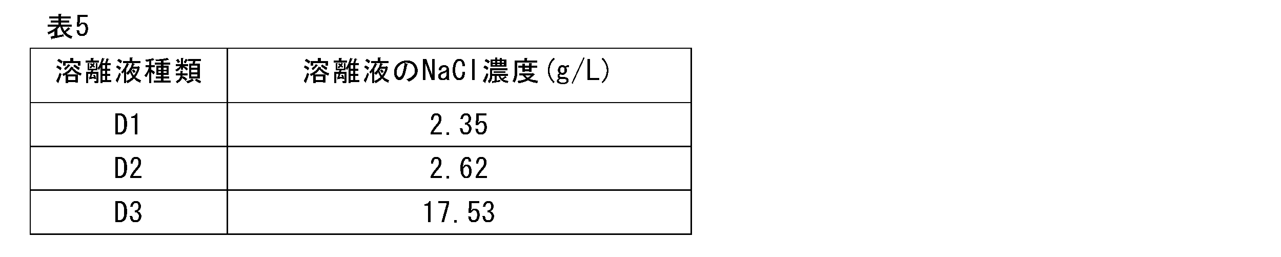
<運転条件>
下記工程1~6を順に行った。工程1~6のフロー図は図10の通りである。<Operating conditions>
The following

<結果>
-回収率-
弱吸着性画分へのフラグメント1及びフラグメント2の回収率、中吸着性画分への抗体の回収率、強吸着性画分への凝集体の回収率を下表に示す。<Results>
-Recovery rate-
The recovery rates of

-分離処理効率-
比較例2における分離処理効率は、12.51(L-原液)/(L-R)・hであった。-Separation processing efficiency-
The separation efficiency in Comparative Example 2 was 12.51 (L-undiluted solution)/(LR)·h.
[比較例3] マルチカラム・グラジエント・擬似移動層方式
<カラム>
直径10mm×長さ100mm 4本
<原液>
原液中のNaCl濃度は2.23g/Lとした。
<溶離液>
下記溶離液を用いた。[Comparative Example 3] Multi-column gradient pseudo moving bed method <Column>
4 pieces (diameter 10mm x length 100mm) <undiluted solution>
The NaCl concentration in the stock solution was 2.23 g/L.
<Eluent>
The following eluent was used.

<運転条件>
図11に比較例3の運転のフロー図を示す。図11に示す第1~第4ステップを1サイクルとして、10サイクル実施した。各ステップの間には、原液供給口F、溶離液供給口D(D1~D3)、弱吸着性画分抜出口A、中吸着性画分抜出口B及び強吸着性画分抜出口Cを、これらの相対的な位置関係を保ったままカラム1つ分だけ下流側へと移行させるステップを行っている。
なお、図11に示す第1~第4ステップは、本発明のステップ(A)に対応するが、当該ステップ(A)とは異なり、複数のサブステップから構成されるものではない(換言すれば、1つのサブステップで1つのステップが構成されている。)。図11中の「D1」、「D2」及び「D3」はいずれも溶離液供給口であり、それぞれ、溶離液D1、D2及びD3が供給される。図11中の「C」は強吸着性画分抜出口であり、強吸着性画分が抜き出される。同様に「B」は中吸着性画分抜出口であり、中吸着性画分が抜き出され、「A」は弱吸着性画分抜出口であり、弱吸着性画分が抜き出される。
図11に示す各ステップにおける溶離液(D1~D3)と原液(F)の供給流速は下記の通りとした。なお、下表には抜き出される液の流速を記載していないが、強吸着性画分抜出口Cから抜き出される強吸着性画分の流速は溶離液D1を供給する流速と同じである。また、中吸着性画分抜出口Bから抜き出される中吸着性画分の流速は溶離液D2を供給する流速と同じである。また、弱吸着性画分抜出口Aから抜き出される弱吸着性画分の流速は、溶離液D3を供給する流速と、原液供給口Fから原液を供給する流速の合計となる。つまり、供給流量と抜出流量は常に同じであり、このことは以降の比較例ないし実施例でも同様である。<Operating conditions>
FIG. 11 shows a flow diagram of the operation of Comparative Example 3. Ten cycles were performed, with the first to fourth steps shown in FIG. 11 being one cycle. Between each step, a stock solution supply port F, an eluent supply port D (D1 to D3), a weakly adsorbent fraction extraction port A, a medium adsorption fraction extraction port B, and a strong adsorption fraction extraction port C are provided. , while maintaining these relative positional relationships, a step is performed in which the components are moved downstream by one column.
Note that the first to fourth steps shown in FIG. 11 correspond to step (A) of the present invention, but unlike step (A), they are not composed of a plurality of substeps (in other words, , one step is composed of one substep). "D1", "D2", and "D3" in FIG. 11 are all eluent supply ports, and eluents D1, D2, and D3 are supplied, respectively. "C" in FIG. 11 is a strongly adsorptive fraction extraction port, from which the strongly adsorptive fraction is extracted. Similarly, "B" is a medium adsorption fraction extraction port, from which the medium adsorptive fraction is extracted, and "A" is a weak adsorption fraction extraction port, from which the weak adsorption fraction is extracted.
The supply flow rates of the eluent (D1 to D3) and stock solution (F) in each step shown in FIG. 11 were as follows. Although the flow rate of the extracted liquid is not listed in the table below, the flow rate of the strongly adsorptive fraction extracted from the strongly adsorptive fraction extraction port C is the same as the flow rate that supplies the eluent D1. . Further, the flow rate of the medium adsorptive fraction extracted from the medium adsorptive fraction extraction port B is the same as the flow rate for supplying the eluent D2. Further, the flow rate of the weakly adsorptive fraction extracted from the weakly adsorptive fraction extraction port A is the sum of the flow rate for supplying the eluent D3 and the flow rate for supplying the stock solution from the stock solution supply port F. In other words, the supply flow rate and the withdrawal flow rate are always the same, and this also applies to subsequent comparative examples and examples.

<結果>
-回収率-
弱吸着性画分へのフラグメント1及びフラグメント2の回収率、中吸着性画分への抗体の回収率、強吸着性画分への凝集体の回収率を下表に示す。<Results>
-Recovery rate-
The recovery rates of

-分離処理効率-
比較例3における分離処理効率は、7.11(L-原液)/(L-R)・hであった。-Separation processing efficiency-
The separation efficiency in Comparative Example 3 was 7.11 (L-undiluted solution)/(LR)·h.
[比較例4] マルチカラム・グラジエント・擬似移動層方式
<カラム>
直径10mm×長さ100mm 4本
<原液>
原液中のNaCl濃度は2.24g/Lとした。
<溶離液>
下記溶離液を用いた。[Comparative Example 4] Multi-column gradient pseudo moving bed method <Column>
4 pieces (diameter 10mm x length 100mm) <undiluted solution>
The NaCl concentration in the stock solution was 2.24 g/L.
<Eluent>
The following eluent was used.

<運転条件>
図12に比較例4の運転のフロー図を示す。図12に示す第1~第4ステップを1サイクルとして、10サイクル実施した。なお、図12に示す各ステップは、第1サブステップと第2サブステップの2つのサブステップから構成され、第2サブステップは液の供給と抜き出しのいずれも行わずに、循環系内の流体を循環させるものである。
図12に示す各ステップにおける溶離液(D1~D3)と原液(F)の供給流速は下記の通りとした。<Operating conditions>
FIG. 12 shows a flow diagram of the operation of Comparative Example 4. Ten cycles were performed, with the first to fourth steps shown in FIG. 12 as one cycle. Note that each step shown in FIG. 12 is composed of two substeps, a first substep and a second substep. It circulates.
The supply flow rates of the eluent (D1 to D3) and stock solution (F) in each step shown in FIG. 12 were as follows.

<結果>
-回収率-
弱吸着性画分へのフラグメント1及び2の回収率、中吸着性画分への抗体の回収率、強吸着性画分への凝集体の回収率を下表に示す。<Results>
-Recovery rate-
The table below shows the recovery rates of

-分離処理効率-
比較例4における分離処理効率は、7.19(L-原液)/(L-R)・hであった。-Separation processing efficiency-
The separation efficiency in Comparative Example 4 was 7.19 (L-undiluted solution)/(LR)·h.
[実施例1] マルチカラム・グラジエント・擬似移動層方式
<カラム>
直径10mm×長さ100mm 4本
<原液>
原液中のNaCl濃度は1.93g/Lとした。
<溶離液>
下記溶離液を用いた。[Example 1] Multi-column gradient pseudo moving bed method <Column>
4 pieces (diameter 10mm x length 100mm) <undiluted solution>
The NaCl concentration in the stock solution was 1.93 g/L.
<Eluent>
The following eluent was used.

<運転条件>
図2に示すサブステップの組み合わせによりステップ(A)を構成した。このステップ(A)とそれに続くステップ(B)を1セットとし、これを4セット行って1サイクルとして、10サイクル実施した。各ステップ(A)における溶離液(D1~D4)と原液(F)の供給流速は下記の通りとした。<Operating conditions>
Step (A) was configured by the combination of substeps shown in FIG. This step (A) and the subsequent step (B) constituted one set, and 4 sets of these were performed as one cycle, and 10 cycles were performed. The supply flow rates of the eluent (D1 to D4) and stock solution (F) in each step (A) were as follows.

<結果>
-回収率-
弱吸着性画分へのフラグメント1及び2の回収率、中吸着性画分への抗体の回収率、強吸着性画分への凝集体の回収率を下表に示す。<Results>
-Recovery rate-
The table below shows the recovery rates of

-分離処理効率-
実施例1における分離処理効率は、19.696(L-原液)/(L-R)・hであった。-Separation processing efficiency-
The separation processing efficiency in Example 1 was 19.696 (L-stock solution)/(LR)·h.
[実施例2] マルチカラム・グラジエント・擬似移動層方式
<カラム>
直径10mm×長さ100mm 4本
<原液>
原液中のNaCl濃度は2.02g/Lとした。
<溶離液>
下記溶離液を用いた。

4 pieces (diameter 10mm x length 100mm) <undiluted solution>
The NaCl concentration in the stock solution was 2.02 g/L.
<Eluent>
The following eluent was used.
<運転条件>
図4に示すサブステップの組み合わせによりステップ(A)を構成した。このステップ(A)とそれに続くステップ(B)を1セットとし、これを4セット行って1サイクルとして、10サイクル実施した。各ステップ(A)における溶離液(D1~D4)と原液(F)の供給流速は下記の通りとした。<Operating conditions>
Step (A) was configured by the combination of substeps shown in FIG. This step (A) and the subsequent step (B) constituted one set, and 4 sets of these were performed as one cycle, and 10 cycles were performed. The supply flow rates of the eluent (D1 to D4) and stock solution (F) in each step (A) were as follows.

<結果>
-回収率-
弱吸着性画分へのフラグメント1及び2の回収率、中吸着性画分への抗体の回収率、強吸着性画分への凝集体の回収率を下表に示す。<Results>
-Recovery rate-
The table below shows the recovery rates of
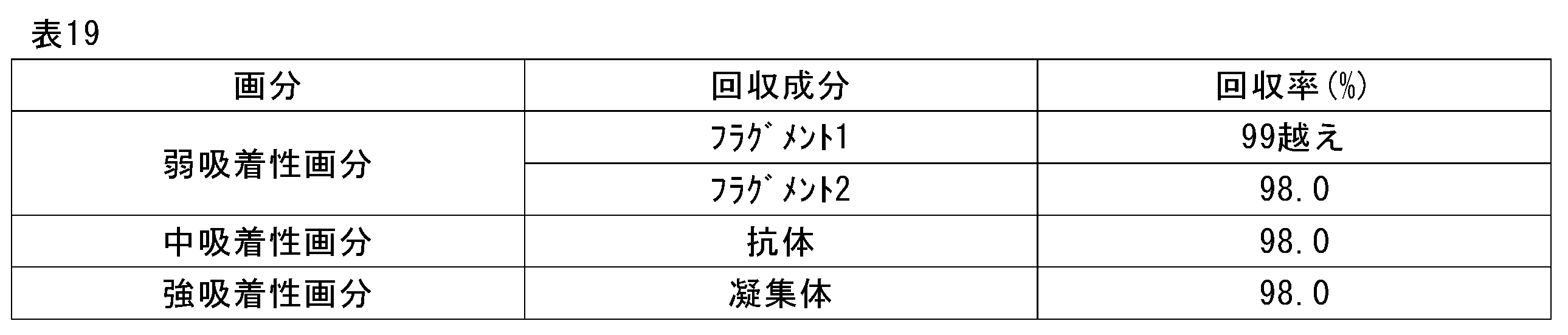
-分離処理効率-
実施例2における分離処理効率は、18.610(L-原液)/(L-R)・hであった。-Separation processing efficiency-
The separation efficiency in Example 2 was 18.610 (L-undiluted solution)/(LR)·h.
[実施例3] マルチカラム・グラジエント・擬似移動層方式
<カラム>
直径10mm×長さ805mm 5本
<原液>
原液中のNaCl濃度は2.46g/Lとした。
<溶離液>
下記溶離液を用いた。

Diameter 10mm x
The NaCl concentration in the stock solution was 2.46 g/L.
<Eluent>
The following eluent was used.
<運転条件>
図6に示すサブステップの組み合わせによりステップ(A)を構成した。このステップ(A)とそれに続くステップ(B)を1セットとし、これを5セット行って1サイクルとして、10サイクル実施した。各ステップ(A)における溶離液(D1~D4)と原液(F)の供給流速は下記の通りとした。<Operating conditions>
Step (A) was configured by the combination of substeps shown in FIG. This step (A) and the subsequent step (B) constituted one set, and 5 sets of these were performed as one cycle, and 10 cycles were performed. The supply flow rates of the eluent (D1 to D4) and stock solution (F) in each step (A) were as follows.

<結果>
-回収率-
弱吸着性画分へのフラグメント1及び2の回収率、中吸着性画分への抗体の回収率、強吸着性画分への凝集体の回収率を下表に示す。<Results>
-Recovery rate-
The table below shows the recovery rates of

-分離処理効率-
実施例3における分離処理効率は、16.499(L-原液)/(L-R)・hであった。-Separation processing efficiency-
The separation efficiency in Example 3 was 16.499 (L-stock solution)/(LR)·h.
[実施例4] マルチカラム・グラジエント・擬似移動層方式
<カラム>
直径10mm×長さ100mm 7本
<原液>
原液中のNaCl濃度は2.57g/Lとした。
<溶離液>
下記溶離液を用いた。

7 pieces (diameter 10mm x length 100mm) <undiluted solution>
The NaCl concentration in the stock solution was 2.57 g/L.
<Eluent>
The following eluent was used.
<運転条件>
図8に示すサブステップの組み合わせによりステップ(A)を構成した。このステップ(A)とそれに続くステップ(B)を1セットとし、これを7セット行って1サイクルとして、10サイクル実施した。各ステップ(A)における溶離液(D1~D5)と原液(F)の供給流速は下記の通りとした。<Operating conditions>
Step (A) was configured by the combination of substeps shown in FIG. This step (A) and the subsequent step (B) constituted one set, and 7 sets of these were performed as one cycle, and 10 cycles were performed. The supply flow rates of the eluent (D1 to D5) and stock solution (F) in each step (A) were as follows.

<結果>
-回収率-
弱吸着性画分へのフラグメント1及び2の回収率、中吸着性画分への抗体の回収率、強吸着性画分への凝集体の回収率を下表に示す。<Results>
-Recovery rate-
The table below shows the recovery rates of

-分離処理効率-
実施例4における分離処理効率は、15.225(L-原液)/(L-R)・hであった。-Separation processing efficiency-
The separation efficiency in Example 4 was 15.225 (L-stock solution)/(LR)·h.
上記の通り、擬似移動層方式クロマト分離において、2種以上の溶離液を用いて、循環系における弱吸着性画分抜出口Aと、中吸着性画分抜出口Bと、強吸着性画分抜出口Cと、原液供給口Fとの位置関係を本発明で規定する特定の関係とすることにより、弱吸着性成分と中吸着性成分と強吸着性成分とを、より少ない吸着剤の使用量で、十分に高純度化して分取できることがわかる。本実施例により、目的の抗体を中吸着性画分中に、高純度に、高効率に得られることが示された。 As mentioned above, in the simulated moving bed chromatographic separation, two or more types of eluents are used to separate the weakly adsorptive fraction in the circulation system from the extraction port A, the medium adsorptive fraction extraction port B, and the strongly adsorptive fraction. By setting the positional relationship between the extraction port C and the stock solution supply port F to the specific relationship defined in the present invention, less adsorbent is used to remove weakly adsorbed components, medium adsorbed components, and strongly adsorbed components. It can be seen that the amount can be sufficiently purified and fractionated. This example demonstrated that the antibody of interest could be obtained with high purity and high efficiency in the medium adsorption fraction.
[実施例5] マルチカラム・グラジエント・擬似移動層方式
<カラム>
直径10mm×長さ80mm 5本
<原液>
原液中のNaCl濃度は2.46g/Lとした。
<溶離液>
下記溶離液を用いた。[Example 5] Multi-column gradient pseudo moving bed method <Column>
Diameter 10mm x
The NaCl concentration in the stock solution was 2.46 g/L.
<Eluent>
The following eluent was used.

図13に示すサブステップの組み合わせによりステップ(A)を構成した。このステップ(A)とそれに続くステップ(B)を1セットとし、これを5セット行って1サイクルとして、10サイクル実施した。各ステップ(A)における溶離液(D1~D4)と原液(F)の供給流速は下記の通りとした。 Step (A) was configured by the combination of substeps shown in FIG. This step (A) and the subsequent step (B) constituted one set, and 5 sets of these were performed as one cycle, and 10 cycles were performed. The supply flow rates of the eluent (D1 to D4) and stock solution (F) in each step (A) were as follows.

<結果>
-回収率-
弱吸着性画分へのフラグメント1及び2の回収率、中吸着性画分への抗体の回収率、強吸着性画分への凝集体の回収率を下表に示す。<Results>
-Recovery rate-
The table below shows the recovery rates of

-分離処理効率-
実施例5における分離処理効率は、16.502(L-原液)/(L-R)・hであった。-Separation processing efficiency-
The separation efficiency in Example 5 was 16.502 (L-stock solution)/(LR)·h.
[実施例6] マルチカラム・グラジエント・擬似移動層方式
<カラム>
直径10mm×長さ80mm 5本
<原液>
原液中のNaCl濃度は2.55g/Lとした。
<溶離液>
下記溶離液を用いた。

Diameter 10mm x
The NaCl concentration in the stock solution was 2.55 g/L.
<Eluent>
The following eluent was used.
<運転条件>
図15に示すサブステップの組み合わせによりステップ(A)を構成した。このステップ(A)とそれに続くステップ(B)を1セットとし、これを5セット行って1サイクルとして、10サイクル実施した。各ステップ(A)における溶離液(D1~D4)と原液(F)の供給流速は下記の通りとした。<Operating conditions>
Step (A) was configured by the combination of substeps shown in FIG. This step (A) and the subsequent step (B) constituted one set, and 5 sets of these were performed as one cycle, and 10 cycles were performed. The supply flow rates of the eluent (D1 to D4) and stock solution (F) in each step (A) were as follows.
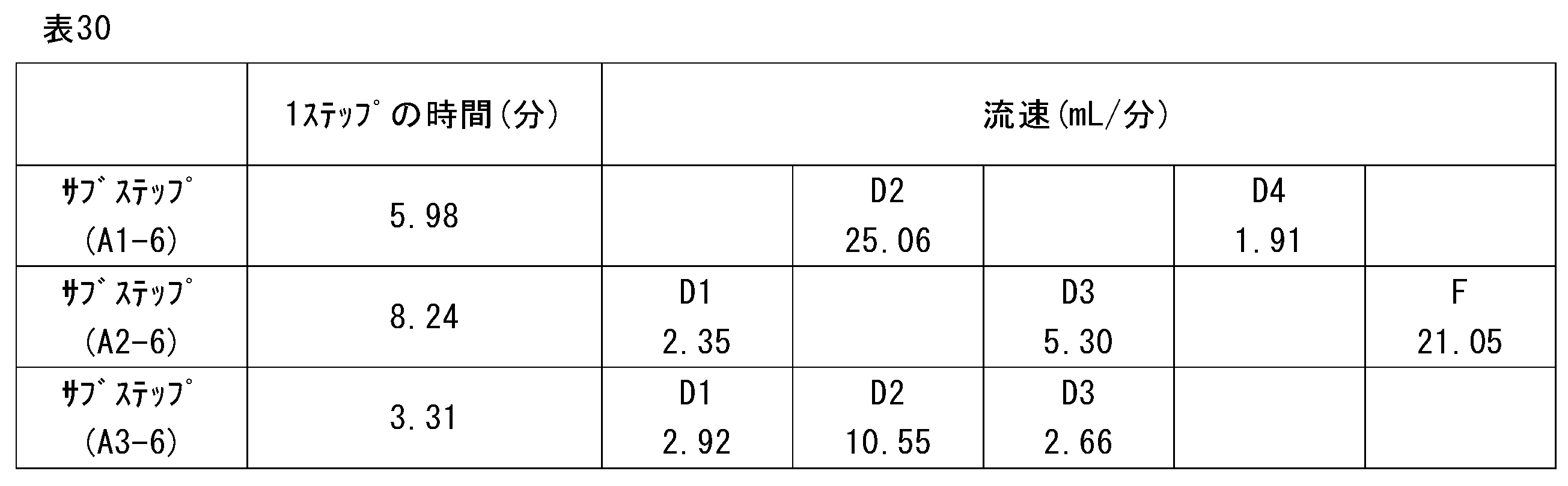
<結果>
-回収率-
弱吸着性画分へのフラグメント1及び2の回収率、中吸着性画分への抗体の回収率、強吸着性画分への凝集体の回収率を下表に示す。<Results>
-Recovery rate-
The table below shows the recovery rates of
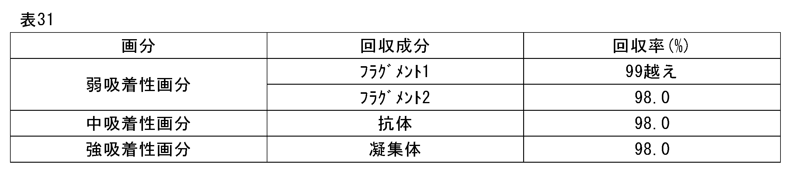
-分離処理効率-
実施例6における分離処理効率は、18.898(L-原液)/(L-R)・hであった。-Separation processing efficiency-
The separation efficiency in Example 6 was 18.898 (L-stock solution)/(LR)·h.
[実施例7] マルチカラム・グラジエント・擬似移動層方式
<カラム>
直径10mm×長さ80mm 5本
<原液>
原液中のNaCl濃度は2.55g/Lとした。
<溶離液>
下記溶離液を用いた。

Diameter 10mm x
The NaCl concentration in the stock solution was 2.55 g/L.
<Eluent>
The following eluent was used.
<運転条件>
図17に示すサブステップの組み合わせによりステップ(A)を構成した。このステップ(A)とそれに続くステップ(B)を1セットとし、これを5セット行って1サイクルとして、10サイクル実施した。各ステップ(A)における溶離液(D1~D4)と原液(F)の供給流速は下記の通りとした。<Operating conditions>
Step (A) was configured by the combination of substeps shown in FIG. This step (A) and the subsequent step (B) constituted one set, and 5 sets of these were performed as one cycle, and 10 cycles were performed. The supply flow rates of the eluent (D1 to D4) and stock solution (F) in each step (A) were as follows.

<結果>
-回収率-
弱吸着性画分へのフラグメント1及び2の回収率、中吸着性画分への抗体の回収率、強吸着性画分への凝集体の回収率を下表に示す。<Results>
-Recovery rate-
The table below shows the recovery rates of

-分離処理効率-
実施例7における分離処理効率は、16.502(L-原液)/(L-R)・hであった。-Separation processing efficiency-
The separation efficiency in Example 7 was 16.502 (L-undiluted solution)/(LR)·h.
[実施例8] マルチカラム・グラジエント・擬似移動層方式
<カラム>
直径10mm×長さ133mm 3本
<原液>
原液中のNaCl濃度は2.21g/Lとした。
<溶離液>
下記溶離液を用いた。

3 bottles (diameter 10mm x length 133mm) <undiluted solution>
The NaCl concentration in the stock solution was 2.21 g/L.
<Eluent>
The following eluent was used.
<運転条件>
図19に示すサブステップの組み合わせによりステップ(A)を構成した。このステップ(A)とそれに続くステップ(B)を1セットとし、これを3セット行って1サイクルとして、10サイクル実施した。各ステップ(A)における溶離液(D1~D4)と原液(F)の供給流速は下記の通りとした。<Operating conditions>
Step (A) was configured by the combination of substeps shown in FIG. This step (A) and the subsequent step (B) constituted one set, and three sets of these were performed as one cycle, and 10 cycles were performed. The supply flow rates of the eluent (D1 to D4) and stock solution (F) in each step (A) were as follows.

<結果>
-回収率-
弱吸着性画分へのフラグメント1及び2の回収率、中吸着性画分への抗体の回収率、強吸着性画分への凝集体の回収率を下表に示す。<Results>
-Recovery rate-
The table below shows the recovery rates of

-分離処理効率-
実施例8における分離処理効率は、17.362(L-原液)/(L-R)・hであった。-Separation processing efficiency-
The separation efficiency in Example 8 was 17.362 (L-undiluted solution)/(LR)·h.
[実施例9] マルチカラム・グラジエント・擬似移動層方式
<カラム>
直径10mm×長さ133mm 3本
<原液>
原液中のNaCl濃度は2.21g/Lとした。
<溶離液>
下記溶離液を用いた。

3 bottles (diameter 10mm x length 133mm) <undiluted solution>
The NaCl concentration in the stock solution was 2.21 g/L.
<Eluent>
The following eluent was used.
<運転条件>
図21に示すサブステップの組み合わせによりステップ(A)を構成した。このステップ(A)とそれに続くステップ(B)を1セットとし、これを3セット行って1サイクルとして、10サイクル実施した。各ステップ(A)における溶離液(D1~D4)と原液(F)の供給流速は下記の通りとした。<Operating conditions>
Step (A) was configured by the combination of substeps shown in FIG. This step (A) and the subsequent step (B) constituted one set, and three sets of these were performed as one cycle, and 10 cycles were performed. The supply flow rates of the eluent (D1 to D4) and stock solution (F) in each step (A) were as follows.

<結果>
-回収率-
弱吸着性画分へのフラグメント1及び2の回収率、中吸着性画分への抗体の回収率、強吸着性画分への凝集体の回収率を下表に示す。<Results>
-Recovery rate-
The table below shows the recovery rates of

-分離処理効率-
実施例9における分離処理効率は、18.956(L-原液)/(L-R)・hであった。-Separation processing efficiency-
The separation efficiency in Example 9 was 18.956 (L-undiluted solution)/(LR)·h.
図23、25及び27に示すサブステップの組み合わせによりステップ(A)を構成した各実施形態についても、上記各実施例と同様にして、マルチカラム・グラジエント・疑似移動層方式により原液のクロマト分離を試みた(実施例10~12)。運転条件は、弱吸着性画分へのフラグメント1及びフラグメント2の回収率が98%以上、中吸着性画分への抗体の回収率が98%以上、かつ、強吸着性画分への凝集体の回収率が98%以上となる条件とした結果、いずれの実施形態においても13(L-原液)/(L-R)・h以上の分離処理効率を実現できた。
In each of the embodiments in which step (A) is configured by the combination of substeps shown in FIGS. 23, 25, and 27, the chromatographic separation of the stock solution is performed using the multicolumn gradient pseudo moving bed method in the same manner as in each of the above embodiments. (Examples 10 to 12). The operating conditions were as follows: the recovery rate of
本発明をその実施態様とともに説明したが、我々は特に指定しない限り我々の発明を説明のどの細部においても限定しようとするものではなく、添付の請求の範囲に示した発明の精神と範囲に反することなく幅広く解釈されるべきであると考える。 Although the invention has been described in conjunction with embodiments thereof, we do not intend to limit our invention in any detail in the description unless otherwise specified and contrary to the spirit and scope of the invention as set forth in the appended claims. I believe that it should be interpreted broadly without any restrictions.
本願は、2020年5月14日に日本国で特許出願された特願2020-085028に基づく優先権を主張するものであり、これはここに参照してその内容を本明細書の記載の一部として取り込む。 This application claims priority based on Japanese Patent Application No. 2020-085028 filed in Japan on May 14, 2020, which is hereby incorporated by reference and its contents are incorporated herein by reference. Incorporate it as a part.
100 循環系
10a、10b、10c、10d 単位充填塔(カラム)
Ab 吸着剤
R1、R2、R3、R4 遮断弁
2a、2b、2c、2d 弱吸着性画分抜出ライン
A1、A2、A3、A4 弱吸着性画分抜出弁
3a、3b、3c、3d 中吸着性画分抜出ライン
B1、B2、B3、B4 中吸着性画分抜出弁
4a、4b、4c、4d 強吸着性画分抜出ライン
C1、C2、C3、C4 強吸着性画分抜出弁
T1、T2、T3、T4 逆止弁
1 配管
2J 弱吸着性画分合流管
3J 中吸着性画分合流管
4J 強吸着性画分合流管
6 原液タンク
7 原液
8a、8b、8c、8d 溶離液タンク
9a、9b、9c、9d 溶離液
11 原液供給ライン
11a、11b、11c、11d 原液供給分岐ライン
F1、F2、F3、F4 原液供給弁
12、13、14、15 溶離液供給ライン
12a、12b、12c、12d 溶離液供給分岐ライン
13a、13b、13c、13d 溶離液供給分岐ライン
14a、14b、14c、14d 溶離液供給分岐ライン
15a、15b、15c、15d 溶離液供給分岐ライン
E1a、E2a、E3a、E4a 溶離液供給弁
E1b、E2b、E3b、E4b 溶離液供給弁
E1c、E2c、E3c、E4c 溶離液供給弁
E1d、E2d、E3d、E4d 溶離液供給弁
P1 循環ポンプ
P2 原液供給ポンプ
P3、P4、P5、P6 溶離液供給ポンプ
100 Circulating
Ab adsorbent R1, R2, R3, R4 Shutoff valve 2a, 2b, 2c, 2d Weakly adsorbent fraction extraction line A1, A2, A3, A4 Weakly adsorbent fraction extraction valve 3a, 3b, 3c, 3d Medium Adsorptive fraction extraction line B1, B2, B3, B4 Medium adsorption fraction extraction valve 4a, 4b, 4c, 4d Strongly adsorptive fraction extraction line C1, C2, C3, C4 Strongly adsorptive fraction extraction Outlet valve T1, T2, T3, T4 Check valve 1 Piping 2J Weak adsorption fraction merging tube 3J Medium adsorption fraction merging tube 4J Strong adsorption fraction merging tube 6 Stock solution tank 7 Stock solution 8a, 8b, 8c, 8d Eluent tank 9a, 9b, 9c, 9d Eluent 11 Stock solution supply line 11a, 11b, 11c, 11d Stock solution supply branch line F1, F2, F3, F4 Stock solution supply valve 12, 13, 14, 15 Eluent supply line 12a, 12b, 12c, 12d Eluent supply branch line 13a, 13b, 13c, 13d Eluent supply branch line 14a, 14b, 14c, 14d Eluent supply branch line 15a, 15b, 15c, 15d Eluent supply branch line E1a, E2a, E3a, E4a Eluent supply valve E1b, E2b, E3b, E4b Eluent supply valve E1c, E2c, E3c, E4c Eluent supply valve E1d, E2d, E3d, E4d Eluent supply valve P1 Circulation pump P2 Stock solution supply pump P3, P4 , P5, P6 Eluent supply pump
Claims (7)
前記循環系の前記配管には、原液供給口Fと、前記2種以上の各溶離液に対応する2つ以上の溶離液供給口Dと、前記弱吸着性成分を含む弱吸着性画分の抜出口Aと、前記中吸着性成分を含む中吸着性画分の抜出口Bと、前記強吸着性成分を含む強吸着性画分の抜出口Cとが設けられ、該原液供給口F、該抜出口A、該抜出口B及び該抜出口Cの位置を下記(a)~(c)とし:
(a)前記抜出口Bを、前記原液供給口Fの、少なくとも1つのセクションを挟んで下流側に設ける;
(b)前記抜出口Cを、前記原液供給口Fを有する配管に設けるか、又は、前記抜出口Cを、前記原液供給口Fの、少なくとも1つのセクションを挟んで上流側に設ける;
(c)前記抜出口Aを、前記抜出口Bを有する配管に設けるか、又は、前記抜出口Aを、前記抜出口Bの、少なくとも1つのセクションを挟んで下流側に設ける;
前記クロマト分離方法は下記ステップ(A)及び(B)を順に繰り返すことを含む、擬似移動層方式クロマト分離方法:
[ステップ(A)]
前記原液供給口Fから原液を、前記2つ以上の溶離液供給口Dから2種以上の溶離液を、それぞれ同時に又は別々に供給し、かつ、前記抜出口Aから弱吸着性画分を、前記抜出口Bから中吸着性画分を、前記抜出口Cから強吸着性画分を、それぞれ同時に又は別々に抜き出すステップ;
[ステップ(B)]
前記ステップ(A)終了後、前記原液供給口F、前記溶離液供給口D、前記抜出口A、前記抜出口B及び前記抜出口Cを、これらの相対的な位置関係を保ったまま下流側へと移行させるステップ。A circulation system in which three or more unit packed columns filled with adsorbent are connected in series and endlessly via piping is used, and the circulation system is connected upstream so that each section has at least one unit packed column. It is divided into three continuous annular sections 1 to 3 from the side to the downstream side, and contains a weakly adsorbable component, a strongly adsorbent component, and an intermediate between the two components contained in the stock solution. A simulated moving bed chromatographic separation method comprising separating a moderately adsorptive component using two or more eluents, the method comprising:
The piping of the circulation system includes a stock solution supply port F, two or more eluent supply ports D corresponding to each of the two or more eluents, and a supply port for the weakly adsorbent fraction containing the weakly adsorbable component. An extraction port A, an extraction port B for the moderately adsorptive fraction containing the medium adsorptive component, and an extraction port C for the strongly adsorptive fraction containing the strongly adsorptive component are provided, and the stock solution supply port F, The positions of the extraction port A, the extraction port B, and the extraction port C are as shown in the following (a) to (c):
(a) the extraction port B is provided downstream of the stock solution supply port F across at least one section;
(b) the extraction port C is provided in a pipe having the stock solution supply port F, or the extraction port C is provided on the upstream side of the stock solution supply port F across at least one section;
(c) the outlet A is provided in a pipe having the outlet B, or the outlet A is provided downstream of the outlet B across at least one section;
The chromatographic separation method includes repeating the following steps (A) and (B) in order, a simulated moving bed chromatographic separation method:
[Step (A)]
Supplying the stock solution from the stock solution supply port F, two or more eluents from the two or more eluent supply ports D, respectively simultaneously or separately, and supplying the weakly adsorbent fraction from the extraction port A, extracting a medium adsorptive fraction from the extraction port B and a strongly adsorptive fraction from the extraction port C, simultaneously or separately;
[Step (B)]
After the step (A) is completed, the stock solution supply port F, the eluent supply port D, the extraction port A, the extraction port B, and the extraction port C are connected to the downstream side while maintaining their relative positional relationships. Steps to transition to.
<サブステップ(A1-8)>
セクション2の上流側末端を原液供給口Fとして該原液供給口Fから原液を供給し、セクション3の下流側末端を前記抜出口Aとして該抜出口Aから弱吸着性画分を抜き出す;
<サブステップ(A2-8)>
セクション1の上流側末端を溶離液供給口D-IIとして該溶離液供給口D-IIから溶離液d-IIを供給し、セクション2の上流側末端を溶離液供給口D-IIIとして該溶離液供給口D-IIIから溶離液d-IIIを供給し、前記抜出口Aから弱吸着性画分を抜き出すことにより、
セクション1を流通する溶離液の脱着力を最も強くし、
セクション2及び3を流通する溶離液の脱着力を、セクション1を流通する溶離液の脱着力よりも弱くする;
<サブステップ(A3-8)>
セクション1の上流側末端を溶離液供給口D-Iとして該溶離液供給口D-Iから溶離液d-Iを供給し、セクション1の下流側末端を前記抜出口Cとして該抜出口Cから強吸着性画分を抜き出し、セクション2の上流側末端を溶離液供給口D-IIとして該溶離液供給口D-IIから溶離液d-IIを供給し、セクション3の上流側末端を溶離液供給口D-IIIとして該溶離液供給口D-IIIから溶離液d-IIIを供給し、前記抜出口Aから弱吸着性画分を抜き出すことにより、
セクション1を流通する溶離液の脱着力を最も強くし、
セクション2を流通する溶離液の脱着力を、セクション1を流通する溶離液の脱着力よりも弱くし、
セクション3を流通する溶離液の脱着力を、セクション2を流通する溶離液の脱着力よりも弱くする;
<サブステップ(A4-8)>
前記溶離液供給口D-Iから前記溶離液d-Iを供給し、前記抜出口Cから強吸着性画分を抜き出し、前記溶離液供給口D-IIから前記溶離液d-IIを供給し、セクション2の下流側末端を前記抜出口Bとして該抜出口Bから中吸着性画分を抜き出し、セクション3の上流側末端を溶離液供給口D-IVとして該溶離液供給口D-IVから溶離液d-IVを供給し、前記抜出口Aから弱吸着性画分を抜き出すことにより、
セクション1を流通する溶離液の脱着力を最も強くし、
セクション2を流通する溶離液の脱着力を、セクション1を流通する溶離液の脱着力よりも弱くし、
セクション3を流通する溶離液の脱着力を、セクション2を流通する溶離液の脱着力よりも弱くする。Claim 1, wherein the following substeps (A1-8), (A2-8), (A3-8) and (A4-8) are performed in the step (A) using the two or more eluents described above. The pseudo moving bed chromatographic separation method described in:
<Substep (A1-8)>
The upstream end of section 2 is set as the stock solution supply port F, and the stock solution is supplied from the stock solution supply port F, and the downstream end of section 3 is set as the extraction port A, and the weakly adsorbent fraction is extracted from the withdrawal port A;
<Substep (A2-8)>
The upstream end of section 1 is used as an eluent supply port D-II to supply eluent d-II from the eluent supply port D-II, and the upstream end of section 2 is used as an eluent supply port D-III to supply the eluent d-II. By supplying the eluent d-III from the liquid supply port D-III and extracting the weakly adsorbent fraction from the extraction port A,
The desorption power of the eluent flowing through section 1 is maximized,
making the desorption force of the eluent flowing through sections 2 and 3 weaker than the desorption force of the eluent flowing through section 1;
<Substep (A3-8)>
The upstream end of section 1 is set as the eluent supply port DI, and the eluent d-I is supplied from the eluent supply port DI, and the downstream end of section 1 is set as the eluent port C, and the eluent d-I is supplied from the eluent port C. The highly adsorbent fraction is extracted, the upstream end of section 2 is used as the eluent supply port D-II, and the eluent d-II is supplied from the eluent supply port D-II, and the upstream end of section 3 is used as the eluent supply port D-II. By supplying the eluent d-III from the eluent supply port D-III as the supply port D-III and extracting the weakly adsorbent fraction from the extraction port A,
The desorption power of the eluent flowing through section 1 is maximized,
The desorption force of the eluent flowing through section 2 is made weaker than the desorption force of the eluent flowing through section 1,
making the desorption force of the eluent flowing through section 3 weaker than the desorption force of the eluent flowing through section 2;
<Substep (A4-8)>
The eluent d-I is supplied from the eluent supply port DI, the strongly adsorptive fraction is extracted from the extraction port C, and the eluent d-II is supplied from the eluent supply port D-II. , the downstream end of section 2 is used as the eluent port B, and the medium adsorptive fraction is extracted from the eluent port B, and the upstream end of section 3 is used as the eluent supply port D-IV, and the medium adsorptive fraction is extracted from the eluent supply port D-IV. By supplying eluent d-IV and extracting the weakly adsorbent fraction from the extraction port A,
The desorption power of the eluent flowing through section 1 is maximized,
The desorption force of the eluent flowing through section 2 is made weaker than the desorption force of the eluent flowing through section 1,
The desorption force of the eluent flowing through section 3 is made weaker than the desorption force of the eluent flowing through section 2.
<サブステップ(A1-9)>
セクション2の上流側末端を原液供給口Fとして該原液供給口Fから原液を供給し、セクション3の下流側末端を前記抜出口Aとして該抜出口Aから弱吸着性画分を抜き出す;
<サブステップ(A2-9)>
セクション1の上流側末端を溶離液供給口D-IIとして該溶離液供給口D-IIから溶離液d-IIを供給し、セクション2の上流側末端を溶離液供給口D-IIIとして該溶離液供給口D-IIIから溶離液d-IIIを供給し、前記抜出口Aから弱吸着性画分を抜き出すことにより、
セクション1を流通する溶離液の脱着力を最も強くし、
セクション2及び3を流通する溶離液の脱着力を、セクション1を流通する溶離液の脱着力よりも弱くする;
<サブステップ(A3-9)>
前記溶離液供給口D-IIから溶離液d-IIを供給し、セクション3の上流側末端を溶離液供給口D-IIIとして該溶離液供給口D-IIIから溶離液d-IIIを供給し、前記抜出口Aから弱吸着性画分を抜き出すことにより、
セクション1及び2を流通する溶離液の脱着力を最も強くし、
セクション3を流通する溶離液の脱着力を、セクション1及び2を流通する溶離液の脱着力よりも弱くする;
<サブステップ(A4-9)>
セクション1の上流側末端を溶離液供給口D-Iとして該溶離液供給口D-Iから溶離液d-Iを供給し、セクション1の下流側末端を強吸着性画分抜出口Cとして該抜出口Cから強吸着性画分を抜き出し、セクション2の上流側末端を溶離液供給口D-IIとして該溶離液供給口D-IIから溶離液d-IIを供給し、セクション2の下流側末端を中吸着性画分抜出口Bとして該抜出口Bから中吸着性画分を抜き出し、セクション3の上流側末端を溶離液供給口D-IVとして該溶離液供給口D-IVから溶離液d-IVを供給し、前記抜出口Aから弱吸着性画分を抜き出すことにより、
セクション1を流通する溶離液の脱着力を最も強くし、
セクション2を流通する溶離液の脱着力を、セクション1を流通する溶離液の脱着力よりも弱くし、
セクション3を流通する溶離液の脱着力を、セクション2を流通する溶離液の脱着力よりも弱くする。Claim 1, wherein the following substeps (A1-9), (A2-9), (A3-9) and (A4-9) are performed in the step (A) using the two or more eluents described above. The pseudo moving bed chromatographic separation method described in:
<Substep (A1-9)>
The upstream end of section 2 is set as the stock solution supply port F, and the stock solution is supplied from the stock solution supply port F, and the downstream end of section 3 is set as the extraction port A, and the weakly adsorbent fraction is extracted from the withdrawal port A;
<Substep (A2-9)>
The upstream end of section 1 is used as an eluent supply port D-II to supply eluent d-II from the eluent supply port D-II, and the upstream end of section 2 is used as an eluent supply port D-III to supply the eluent d-II. By supplying the eluent d-III from the liquid supply port D-III and extracting the weakly adsorbent fraction from the extraction port A,
The desorption power of the eluent flowing through section 1 is maximized,
making the desorption force of the eluent flowing through sections 2 and 3 weaker than the desorption force of the eluent flowing through section 1;
<Substep (A3-9)>
The eluent d-II is supplied from the eluent supply port D-II, and the eluent d-III is supplied from the eluent supply port D-III by using the upstream end of section 3 as the eluent supply port D-III. , by extracting the weakly adsorbent fraction from the extraction port A,
The desorption power of the eluent flowing through sections 1 and 2 is maximized,
making the desorption force of the eluent flowing through section 3 weaker than the desorption force of the eluent flowing through sections 1 and 2;
<Substep (A4-9)>
The upstream end of section 1 is set as the eluent supply port DI, and the eluent d-I is supplied from the eluent supply port DI, and the downstream end of section 1 is set as the strongly adsorptive fraction extraction port C. The highly adsorbent fraction is extracted from the extraction port C, and the upstream end of section 2 is set as the eluent supply port D-II, and the eluent d-II is supplied from the eluent supply port D-II. The end of section 3 is set as medium adsorption fraction extraction port B, and the medium adsorptive fraction is extracted from the exit port B, and the upstream end of section 3 is set as eluent supply port D-IV, and the eluent is extracted from the eluent supply port D-IV. By supplying d-IV and extracting the weakly adsorbent fraction from the extraction port A,
The desorption power of the eluent flowing through section 1 is maximized,
The desorption force of the eluent flowing through section 2 is made weaker than the desorption force of the eluent flowing through section 1,
The desorption force of the eluent flowing through section 3 is made weaker than the desorption force of the eluent flowing through section 2.
<サブステップ(A1-10)>
セクション2の上流側末端を前記原液供給口Fとして該原液供給口Fから原液を供給し、セクション3の下流側末端を前記抜出口Aとして該抜出口Aから弱吸着性画分を抜き出す;
<サブステップ(A2-10)>
セクション2の上流側末端を溶離液供給口D-IVとして、該溶離液供給口D-IVから、前記原液と脱着力が同じ又は前記原液よりも脱着力が強い溶離液d-IVを供給し、前記抜出口Aから弱吸着性画分を抜き出す;
<サブステップ(A3-10)>
セクション1の上流側末端を溶離液供給口D-Iとして該溶離液供給口D-Iから溶離液d-Iを供給し、セクション1の下流側末端を前記抜出口Cとして該抜出口Cから強吸着性画分を抜き出し、セクション2の上流側末端を溶離液供給口D-IIとして該溶離液供給口D-IIから溶離液d-IIを供給し、セクション3の上流側末端を溶離液供給口D-IIIとして該溶離液供給口D-IIIから溶離液d-IIIを供給し、前記抜出口Aから弱吸着性画分を抜き出すことにより、
セクション1を流通する溶離液の脱着力を最も強くし、
セクション2を流通する溶離液の脱着力を、セクション1を流通する溶離液の脱着力よりも弱くし、
セクション3を流通する溶離液の脱着力を、セクション2を流通する溶離液の脱着力よりも弱くする;
<サブステップ(A4-10)>
前記溶離液供給口D-Iから前記溶離液d-Iを供給し、前記抜出口Cから強吸着性画分を抜き出し、前記溶離液供給口D-IIから前記溶離液d-IIを供給し、セクション2の下流側末端を前記抜出口Bとして該抜出口Bから中吸着性画分を抜き出し、セクション3の上流側末端を溶離液供給口D-IVとして該溶離液供給口D-IVから溶離液d-IVを供給し、前記抜出口Aから弱吸着性画分を抜き出すことにより、
セクション1を流通する溶離液の脱着力を最も強くし、
セクション2を流通する溶離液の脱着力を、セクション1を流通する溶離液の脱着力よりも弱くし、
セクション3を流通する溶離液の脱着力を、セクション2を流通する溶離液の脱着力よりも弱くする。Claim 1, wherein the following substeps (A1-10), (A2-10), (A3-10) and (A4-10) are performed in the step (A) using the two or more eluents. The pseudo moving bed chromatographic separation method described in:
<Substep (A1-10)>
The upstream end of section 2 is set as the stock solution supply port F, and the stock solution is supplied from the stock solution supply port F, and the downstream end of section 3 is set as the withdrawal port A, and the weakly adsorbent fraction is extracted from the withdrawal port A;
<Substep (A2-10)>
The upstream end of section 2 is set as an eluent supply port D-IV, and an eluent d-IV having the same desorption power as the stock solution or stronger desorption power than the stock solution is supplied from the eluent supply port D-IV. , extracting the weakly adsorbent fraction from the extraction port A;
<Substep (A3-10)>
The upstream end of section 1 is set as the eluent supply port DI, and the eluent d-I is supplied from the eluent supply port DI, and the downstream end of section 1 is set as the eluent port C, and the eluent d-I is supplied from the eluent port C. The highly adsorbent fraction is extracted, the upstream end of section 2 is used as the eluent supply port D-II, and the eluent d-II is supplied from the eluent supply port D-II, and the upstream end of section 3 is used as the eluent supply port D-II. By supplying the eluent d-III from the eluent supply port D-III as the supply port D-III and extracting the weakly adsorbent fraction from the extraction port A,
The desorption power of the eluent flowing through section 1 is maximized,
The desorption force of the eluent flowing through section 2 is made weaker than the desorption force of the eluent flowing through section 1,
making the desorption force of the eluent flowing through section 3 weaker than the desorption force of the eluent flowing through section 2;
<Substep (A4-10)>
The eluent d-I is supplied from the eluent supply port DI, the strongly adsorptive fraction is extracted from the extraction port C, and the eluent d-II is supplied from the eluent supply port D-II. , the downstream end of section 2 is used as the eluent port B, and the medium adsorptive fraction is extracted from the eluent port B, and the upstream end of section 3 is used as the eluent supply port D-IV, and the medium adsorptive fraction is extracted from the eluent supply port D-IV. By supplying eluent d-IV and extracting the weakly adsorbent fraction from the extraction port A,
The desorption power of the eluent flowing through section 1 is maximized,
The desorption force of the eluent flowing through section 2 is made weaker than the desorption force of the eluent flowing through section 1,
The desorption force of the eluent flowing through section 3 is made weaker than the desorption force of the eluent flowing through section 2.
前記循環系の前記配管には、原液供給口Fと、前記2種以上の各溶離液に対応する2つ以上の溶離液供給口Dと、前記弱吸着性成分を含む弱吸着性画分の抜出口Aと、前記中吸着性成分を含む中吸着性画分の抜出口Bと、前記強吸着性成分を含む強吸着性画分の抜出口Cとが設けられ、該原液供給口F、該抜出口A、該抜出口B及び該抜出口Cの位置を下記(a)~(c)とし:
(a)前記抜出口Bを、前記原液供給口Fの、少なくとも1つのセクションを挟んで下流側に設ける;
(b)前記抜出口Cを、前記原液供給口Fを有する配管に設けるか、又は、前記抜出口Cを、前記原液供給口Fの、少なくとも1つのセクション挟んで上流側に設ける;
(c)前記抜出口Aを、前記抜出口Bを有する配管に設けるか、又は、前記抜出口Aを、前記抜出口Bの、少なくとも1つのセクションを挟んで下流側に設ける;
前記クロマト分離方法は下記ステップ(A)及び(B)を順に繰り返すことを含む、擬似移動層方式クロマト分離方法:
[ステップ(A)]
前記原液供給口Fから原液を、前記2つ以上の溶離液供給口Dから2種以上の溶離液を、それぞれ同時に又は別々に供給し、かつ、前記抜出口Aから弱吸着性画分を、前記抜出口Bから中吸着性画分を、前記抜出口Cから強吸着性画分を、それぞれ同時に又は別々に抜き出すステップ;
[ステップ(B)]
前記ステップ(A)終了後、前記原液供給口F、前記溶離液供給口D、前記抜出口A、前記抜出口B及び前記抜出口Cを、これらの相対的な位置関係を保ったまま下流側へと移行させるステップ。A circulation system in which five or more unit packed columns filled with adsorbent are connected in series and endlessly via piping is used, and the circulation system is connected upstream so that each section has at least one unit packed column. It is divided into five continuous annular sections 1 to 5 from the side to the downstream side, and contains a weakly adsorbable component, a strongly adsorbent component, and an intermediate between the two components contained in the stock solution. A simulated moving bed chromatographic separation method comprising separating a moderately adsorptive component using two or more eluents, the method comprising:
The piping of the circulation system includes a stock solution supply port F, two or more eluent supply ports D corresponding to each of the two or more eluents, and a supply port for the weakly adsorbent fraction containing the weakly adsorbable component. An extraction port A, an extraction port B for the moderately adsorptive fraction containing the medium adsorptive component, and an extraction port C for the strongly adsorptive fraction containing the strongly adsorptive component are provided, and the stock solution supply port F, The positions of the extraction port A, the extraction port B, and the extraction port C are as shown in the following (a) to (c):
(a) the extraction port B is provided downstream of the stock solution supply port F across at least one section;
(b) The extraction port C is provided in a pipe having the stock solution supply port F, or the withdrawal port C is provided on the upstream side of the stock solution supply port F across at least one section;
(c) the outlet A is provided in a pipe having the outlet B, or the outlet A is provided downstream of the outlet B across at least one section;
The chromatographic separation method includes repeating the following steps (A) and (B) in order, a simulated moving bed chromatographic separation method:
[Step (A)]
Supplying the stock solution from the stock solution supply port F, two or more eluents from the two or more eluent supply ports D, respectively simultaneously or separately, and supplying the weakly adsorbent fraction from the extraction port A, extracting a medium adsorptive fraction from the extraction port B and a strongly adsorptive fraction from the extraction port C, simultaneously or separately;
[Step (B)]
After the step (A) is completed, the stock solution supply port F, the eluent supply port D, the extraction port A, the extraction port B, and the extraction port C are connected to the downstream side while maintaining their relative positional relationships. Steps to transition to.
<サブステップ(A1-11)>
セクション3の上流側末端を前記原液供給口Fとして該原液供給口Fから原液を供給し、セクション4の上流側末端を溶離液供給口D-IIIとして該溶離液供給口D-IIIから溶離液d-IIIを供給し、セクション5の下流側末端を前記抜出口Aとして該抜出口Aから弱吸着性画分を抜き出すことにより、
セクション3を流通する溶離液の脱着力を最も強くし、
セクション4及び5を流通する溶離液の脱着力を、セクション3を流通する溶離液の脱着力よりも弱くする;
<サブステップ(A2-11)>
セクション1の上流側末端を溶離液供給口D-Iとして該溶離液供給口D-Iから溶離液d-Iを供給し、セクション1の下流側末端を前記抜出口Cとして該抜出口Cから強吸着性画分を抜き出し、セクション2の上流側末端を溶離液供給口D-IIとして該溶離液供給口D-IIから溶離液d-IIを供給し、前記溶離液供給口D-IIIから前記溶離液d-IIIを供給し、前記抜出口Aから弱吸着性画分を抜き出すことにより、
セクション1を流通する溶離液の脱着力を最も強くし、
セクション2及び3を流通する溶離液の脱着力を、セクション1を流通する溶離液の脱着力よりも弱くし、
セクション4及び5を流通する溶離液の脱着力を、セクション2及び3を流通する溶離液の脱着力よりも弱くする;
<サブステップ(A3-11)>
前記溶離液供給口D-Iから前記溶離液d-Iを供給し、前記抜出口Cから強吸着性画分を抜き出し、前記溶離液供給口D-IIから前記溶離液d-IIを供給し、セクション3の下流側末端を前記抜出口Bとして該抜出口Bから中吸着性画分を抜き出し、セクション4の上流側末端を溶離液供給口D-IVとして該溶離液供給口D-IVから溶離液d-IVを供給し、前記抜出口Aから弱吸着性画分を抜き出すことにより、
セクション1を流通する溶離液の脱着力を最も強くし、
セクション2及び3を流通する溶離液の脱着力を、セクション1を流通する溶離液の脱着力よりも弱くし、
セクション4及び5を流通する溶離液の脱着力を、セクション2及び3を流通する溶離液の脱着力よりも弱くする。The pseudo mobile layer according to claim 5, wherein the following substeps (A1-11), (A2-11) and (A3-11) are performed in the step (A) using the two or more eluents. Method chromatographic separation method:
<Substep (A1-11)>
The upstream end of section 3 is set as the stock solution supply port F, and the stock solution is supplied from the stock solution supply port F, and the upstream end of section 4 is set as the eluent supply port D-III, and the eluate is supplied from the eluent supply port D-III. By supplying d-III and extracting the weakly adsorbent fraction from the outlet A by using the downstream end of section 5 as the outlet A,
The desorption power of the eluent flowing through section 3 is maximized,
making the desorption force of the eluent flowing through sections 4 and 5 weaker than the desorption force of the eluent flowing through section 3;
<Substep (A2-11)>
The upstream end of section 1 is set as the eluent supply port DI, and the eluent d-I is supplied from the eluent supply port DI, and the downstream end of section 1 is set as the eluent port C, and the eluent d-I is supplied from the eluent port C. The highly adsorbent fraction is extracted, and the upstream end of section 2 is set as the eluent supply port D-II, and the eluent d-II is supplied from the eluent supply port D-II, and the eluent d-II is supplied from the eluent supply port D-III. By supplying the eluent d-III and extracting the weakly adsorbent fraction from the extraction port A,
The desorption power of the eluent flowing through section 1 is maximized,
The desorption force of the eluent flowing through sections 2 and 3 is made weaker than the desorption force of the eluent flowing through section 1,
making the desorption force of the eluent flowing through sections 4 and 5 weaker than the desorption force of the eluent flowing through sections 2 and 3;
<Substep (A3-11)>
The eluent d-I is supplied from the eluent supply port DI, the strongly adsorptive fraction is extracted from the extraction port C, and the eluent d-II is supplied from the eluent supply port D-II. , the downstream end of section 3 is used as the extraction port B, and the medium adsorptive fraction is extracted from the extraction port B, and the upstream end of section 4 is used as the eluent supply port D-IV, and the medium adsorbent fraction is extracted from the eluent supply port D-IV. By supplying eluent d-IV and extracting the weakly adsorbent fraction from the extraction port A,
The desorption power of the eluent flowing through section 1 is maximized,
The desorption force of the eluent flowing through sections 2 and 3 is made weaker than the desorption force of the eluent flowing through section 1,
The desorption force of the eluent flowing through sections 4 and 5 is made weaker than the desorption force of the eluent flowing through sections 2 and 3.
<サブステップ(A1-12)>
セクション3の上流側末端を前記原液供給口Fとして該原液供給口Fから原液を供給し、セクション5の下流側末端を前記抜出口Aとして該抜出口Aから弱吸着性画分を抜き出す;
<サブステップ(A2-12)>
セクション3の上流側末端を溶離液供給口D-IVとして、該溶離液供給口D-IVから、前記原液と脱着力が同じ又は前記原液よりも脱着力が強い溶離液d-IVを供給し、前記抜出口Aから弱吸着性画分を抜き出す;
<サブステップ(A3-12)>
セクション1の上流側末端を溶離液供給口D-Iとして該溶離液供給口D-Iから溶離液d-Iを供給し、セクション1の下流側末端を前記抜出口Cとして該抜出口Cから強吸着性画分を抜き出し、セクション2の上流側末端を溶離液供給口D-IIとして該溶離液供給口D-IIから溶離液d-IIを供給し、セクション4の上流側末端を溶離液供給口D-IIIとして該溶離液供給口D-IIIから溶離液d-IIIを供給し、前記抜出口Aから弱吸着性画分を抜き出すことにより、
セクション1を流通する溶離液の脱着力を最も強くし、
セクション2及び3を流通する溶離液の脱着力を、セクション1を流通する溶離液の脱着力よりも弱くし、
セクション4及び5を流通する溶離液の脱着力を、セクション2及び3を流通する溶離液の脱着力よりも弱くする;
<サブステップ(A4-12)>
前記溶離液供給口D-Iから前記溶離液d-Iを供給し、前記抜出口Cから強吸着性画分を抜き出し、前記溶離液供給口D-IIから前記溶離液d-IIを供給し、セクション3の下流側末端を前記抜出口Bとして該抜出口Bから中吸着性画分を抜き出し、セクション4の上流側末端を溶離液供給口D-IVとして該溶離液供給口D-IVから溶離液d-IVを供給し、前記抜出口Aから弱吸着性画分を抜き出すことにより、
セクション1を流通する溶離液の脱着力を最も強くし、
セクション2及び3を流通する溶離液の脱着力を、セクション1を流通する溶離液の脱着力よりも弱くし、
セクション4及び5を流通する溶離液の脱着力を、セクション2及び3を流通する溶離液の脱着力よりも弱くする。Claim 5, wherein the following substeps (A1-12), (A2-12), (A3-12) and (A4-12) are performed in the step (A) using the two or more eluents. The pseudo moving bed chromatographic separation method described in:
<Substep (A1-12)>
The upstream end of section 3 is set as the stock solution supply port F, and the stock solution is supplied from the stock solution supply port F, and the downstream end of section 5 is set as the withdrawal port A, and the weakly adsorbent fraction is extracted from the withdrawal port A;
<Substep (A2-12)>
The upstream end of section 3 is set as an eluent supply port D-IV, and from the eluent supply port D-IV, an eluent d-IV having the same desorption power as the stock solution or stronger desorption power than the stock solution is supplied. , extracting the weakly adsorbent fraction from the extraction port A;
<Substep (A3-12)>
The upstream end of section 1 is set as the eluent supply port DI, and the eluent d-I is supplied from the eluent supply port DI, and the downstream end of section 1 is set as the eluent port C, and the eluent d-I is supplied from the eluent port C. The highly adsorbent fraction is extracted, the upstream end of section 2 is used as the eluent supply port D-II, and the eluent d-II is supplied from the eluent supply port D-II, and the upstream end of section 4 is used as the eluent supply port D-II. By supplying the eluent d-III from the eluent supply port D-III as the supply port D-III and extracting the weakly adsorbent fraction from the extraction port A,
The desorption power of the eluent flowing through section 1 is maximized,
The desorption force of the eluent flowing through sections 2 and 3 is made weaker than the desorption force of the eluent flowing through section 1,
making the desorption force of the eluent flowing through sections 4 and 5 weaker than the desorption force of the eluent flowing through sections 2 and 3;
<Substep (A4-12)>
The eluent d-I is supplied from the eluent supply port DI, the strongly adsorptive fraction is extracted from the extraction port C, and the eluent d-II is supplied from the eluent supply port D-II. , the downstream end of section 3 is used as the extraction port B, and the medium adsorptive fraction is extracted from the extraction port B, and the upstream end of section 4 is used as the eluent supply port D-IV, and the medium adsorbent fraction is extracted from the eluent supply port D-IV. By supplying eluent d-IV and extracting the weakly adsorbent fraction from the extraction port A,
The desorption power of the eluent flowing through section 1 is maximized,
The desorption force of the eluent flowing through sections 2 and 3 is made weaker than the desorption force of the eluent flowing through section 1,
The desorption force of the eluent flowing through sections 4 and 5 is made weaker than the desorption force of the eluent flowing through sections 2 and 3.
Applications Claiming Priority (3)
| Application Number | Priority Date | Filing Date | Title |
|---|---|---|---|
| JP2020085028 | 2020-05-14 | ||
| JP2020085028 | 2020-05-14 | ||
| PCT/JP2021/017468 WO2021230144A1 (en) | 2020-05-14 | 2021-05-07 | Chromatographic separation method using simulated moving-bed technique, and chromatographic separation system using simulated moving-bed technique |
Publications (2)
| Publication Number | Publication Date |
|---|---|
| JPWO2021230144A1 JPWO2021230144A1 (en) | 2021-11-18 |
| JP7367206B2 true JP7367206B2 (en) | 2023-10-23 |
Family
ID=78525805
Family Applications (1)
| Application Number | Title | Priority Date | Filing Date |
|---|---|---|---|
| JP2022521869A Active JP7367206B2 (en) | 2020-05-14 | 2021-05-07 | Simulated moving bed chromatographic separation method and simulated moving bed chromatographic separation system |
Country Status (7)
| Country | Link |
|---|---|
| US (1) | US20230338871A1 (en) |
| EP (1) | EP4151297A1 (en) |
| JP (1) | JP7367206B2 (en) |
| KR (1) | KR20220140860A (en) |
| CN (1) | CN115485046B (en) |
| TW (1) | TW202202217A (en) |
| WO (1) | WO2021230144A1 (en) |
Citations (7)
| Publication number | Priority date | Publication date | Assignee | Title |
|---|---|---|---|---|
| JP2006064631A (en) | 2004-08-30 | 2006-03-09 | Japan Organo Co Ltd | Pseudo-moving bed type chromatographic separation method and device |
| JP2007064944A (en) | 2005-09-02 | 2007-03-15 | Japan Organo Co Ltd | Chromatography |
| US20120076191A1 (en) | 2010-09-24 | 2012-03-29 | Nicholas Cowley | Apparatus and method to process signals from one or more transmission sources |
| JP2014029294A (en) | 2012-07-31 | 2014-02-13 | Nippon Rensui Co Ltd | Chromatographic separation method |
| US20140251912A1 (en) | 2011-10-11 | 2014-09-11 | Georgia Tech Research Corporation | Methods and Controllers for Simulated Moving Bed Chromatography for Multicomponent Separation |
| JP2017205721A (en) | 2016-05-20 | 2017-11-24 | フィトファーマ株式会社 | Chromatographic separation method and device for separating multicomponent into three or more fraction |
| WO2020100471A1 (en) | 2018-11-16 | 2020-05-22 | オルガノ株式会社 | Chromatographic separation method using simulated moving-bed technique, and chromatographic separation system using simulated moving-bed technique |
Family Cites Families (14)
| Publication number | Priority date | Publication date | Assignee | Title |
|---|---|---|---|---|
| JPH0198860A (en) | 1987-10-12 | 1989-04-17 | Matsushita Refrig Co Ltd | Heat pump type air conditioner |
| JPH10860A (en) | 1996-06-18 | 1998-01-06 | Ricoh Co Ltd | Optical recording medium |
| US6004518A (en) * | 1997-12-12 | 1999-12-21 | Uop Llc | High-purity simulated moving bed adsorptive separation apparatus |
| CN2484564Y (en) * | 2001-06-06 | 2002-04-03 | 浙江大学 | Chromatographic apparatus of analog moving bed with open loop structure |
| WO2007144476A1 (en) * | 2006-06-16 | 2007-12-21 | Groupe Novasep | Multi-column sequence separation method |
| FR2907021B1 (en) * | 2006-10-16 | 2009-02-06 | Inst Francais Du Petrole | METHOD AND DEVICE FOR SEPARATING A MOBILE BED SIMULATED AT A NUMBER OF LOW DIAMETER REDUCED VALVES |
| JP4945364B2 (en) | 2007-07-31 | 2012-06-06 | オルガノ株式会社 | Separation method of sugar alcohol |
| CN101391159B (en) * | 2008-10-13 | 2010-09-29 | 浙江大学宁波理工学院 | Improved simulated moving bed separation method |
| CN101402003B (en) * | 2008-11-03 | 2010-11-03 | 浙江大学宁波理工学院 | Improved simulated moving bed chromatographic fractionation system |
| CN201618442U (en) * | 2009-12-08 | 2010-11-03 | 辽宁科技大学 | Three-band analogue moving bed chromatogram device |
| CN206334397U (en) * | 2016-09-19 | 2017-07-18 | 辽宁科技大学 | A kind of moving bed imitation chromatogram separation facility |
| JP6912320B2 (en) * | 2017-08-09 | 2021-08-04 | オルガノ株式会社 | Chromatographic separation method and chromatographic separation system |
| JP7225024B2 (en) * | 2018-11-16 | 2023-02-20 | オルガノ株式会社 | Simulated moving bed chromatographic separation method and simulated moving bed chromatographic separation system |
| CN110465114B (en) * | 2019-08-23 | 2021-08-20 | 内蒙古金达威药业有限公司 | Simulated moving bed continuous chromatography chromatographic system, application thereof and method for purifying coenzyme Q10 |
-
2021
- 2021-05-07 EP EP21803387.6A patent/EP4151297A1/en active Pending
- 2021-05-07 WO PCT/JP2021/017468 patent/WO2021230144A1/en unknown
- 2021-05-07 KR KR1020227033321A patent/KR20220140860A/en unknown
- 2021-05-07 US US17/924,407 patent/US20230338871A1/en active Pending
- 2021-05-07 JP JP2022521869A patent/JP7367206B2/en active Active
- 2021-05-07 CN CN202180032253.5A patent/CN115485046B/en active Active
- 2021-05-12 TW TW110117010A patent/TW202202217A/en unknown
Patent Citations (7)
| Publication number | Priority date | Publication date | Assignee | Title |
|---|---|---|---|---|
| JP2006064631A (en) | 2004-08-30 | 2006-03-09 | Japan Organo Co Ltd | Pseudo-moving bed type chromatographic separation method and device |
| JP2007064944A (en) | 2005-09-02 | 2007-03-15 | Japan Organo Co Ltd | Chromatography |
| US20120076191A1 (en) | 2010-09-24 | 2012-03-29 | Nicholas Cowley | Apparatus and method to process signals from one or more transmission sources |
| US20140251912A1 (en) | 2011-10-11 | 2014-09-11 | Georgia Tech Research Corporation | Methods and Controllers for Simulated Moving Bed Chromatography for Multicomponent Separation |
| JP2014029294A (en) | 2012-07-31 | 2014-02-13 | Nippon Rensui Co Ltd | Chromatographic separation method |
| JP2017205721A (en) | 2016-05-20 | 2017-11-24 | フィトファーマ株式会社 | Chromatographic separation method and device for separating multicomponent into three or more fraction |
| WO2020100471A1 (en) | 2018-11-16 | 2020-05-22 | オルガノ株式会社 | Chromatographic separation method using simulated moving-bed technique, and chromatographic separation system using simulated moving-bed technique |
Also Published As
| Publication number | Publication date |
|---|---|
| JPWO2021230144A1 (en) | 2021-11-18 |
| WO2021230144A1 (en) | 2021-11-18 |
| US20230338871A1 (en) | 2023-10-26 |
| EP4151297A1 (en) | 2023-03-22 |
| KR20220140860A (en) | 2022-10-18 |
| TW202202217A (en) | 2022-01-16 |
| CN115485046A (en) | 2022-12-16 |
| CN115485046B (en) | 2024-03-12 |
Similar Documents
| Publication | Publication Date | Title |
|---|---|---|
| JP7225024B2 (en) | Simulated moving bed chromatographic separation method and simulated moving bed chromatographic separation system | |
| JP5330499B2 (en) | Gradient elution multi-column separation method | |
| TW201144327A (en) | Single unit antibody purification | |
| JP2962594B2 (en) | How to separate multiple components | |
| JP7367206B2 (en) | Simulated moving bed chromatographic separation method and simulated moving bed chromatographic separation system | |
| WO2020100471A1 (en) | Chromatographic separation method using simulated moving-bed technique, and chromatographic separation system using simulated moving-bed technique | |
| WO2005097286A1 (en) | Chromatographic separation equipment | |
| JP6013639B1 (en) | Chromatographic separation method and apparatus for separating multiple components into three or more fractions | |
| JPH08178908A (en) | Separating method by chromatography in pseudo-moving phase wherein gap volume caused by deviation of period synchronization is corrected | |
| WO2017029949A1 (en) | Chromatographic separation method and chromatographic separation system | |
| WO2023181655A1 (en) | Simulated moving-bed chromatographic separation method and simulated moving-bed chromatographic separation system | |
| CN118019974A (en) | Simulated moving bed type chromatographic separation method and simulated moving bed type chromatographic separation system | |
| CN108043172A (en) | A kind of method of zeolite molecular sieve separation of methane and nitrogen | |
| JPH03134562A (en) | Dummy mobile layer type chromatographic separation apparatus | |
| JPH04227804A (en) | Method for separating multiple components and device therefor | |
| JP2965747B2 (en) | Multicomponent separation method and apparatus | |
| Bisschops et al. | Dynamic simulations as a predictive model for a multicolumn chromatography separation | |
| JP2019032284A (en) | Chromatographic separation method and chromatographic separation system | |
| JPH0639206A (en) | Pseudo moving-bed liquid chromatographic separator | |
| JP4603114B2 (en) | Method and apparatus for separating a plurality of components contained in a liquid | |
| JP2968107B2 (en) | Chromatographic separation method | |
| CN213853215U (en) | Multi-column continuous sample loading and purifying device | |
| JP3359762B2 (en) | How to separate multiple components | |
| CN108096995A (en) | A kind of method based on new HEU types zeolite molecular sieve separation of methane and nitrogen | |
| JP2648366B2 (en) | Separation method using simulated moving bed |
Legal Events
| Date | Code | Title | Description |
|---|---|---|---|
| A621 | Written request for application examination |
Free format text: JAPANESE INTERMEDIATE CODE: A621 Effective date: 20220721 |
|
| A131 | Notification of reasons for refusal |
Free format text: JAPANESE INTERMEDIATE CODE: A131 Effective date: 20230613 |
|
| TRDD | Decision of grant or rejection written | ||
| A01 | Written decision to grant a patent or to grant a registration (utility model) |
Free format text: JAPANESE INTERMEDIATE CODE: A01 Effective date: 20230926 |
|
| A61 | First payment of annual fees (during grant procedure) |
Free format text: JAPANESE INTERMEDIATE CODE: A61 Effective date: 20231011 |
|
| R150 | Certificate of patent or registration of utility model |
Ref document number: 7367206 Country of ref document: JP Free format text: JAPANESE INTERMEDIATE CODE: R150 |