JP7362997B2 - Turbine blades and turbines including the same - Google Patents
Turbine blades and turbines including the same Download PDFInfo
- Publication number
- JP7362997B2 JP7362997B2 JP2022100584A JP2022100584A JP7362997B2 JP 7362997 B2 JP7362997 B2 JP 7362997B2 JP 2022100584 A JP2022100584 A JP 2022100584A JP 2022100584 A JP2022100584 A JP 2022100584A JP 7362997 B2 JP7362997 B2 JP 7362997B2
- Authority
- JP
- Japan
- Prior art keywords
- width
- turbine
- turbine blade
- groove portion
- inlet
- Prior art date
- Legal status (The legal status is an assumption and is not a legal conclusion. Google has not performed a legal analysis and makes no representation as to the accuracy of the status listed.)
- Active
Links
Images


Classifications
-
- F—MECHANICAL ENGINEERING; LIGHTING; HEATING; WEAPONS; BLASTING
- F01—MACHINES OR ENGINES IN GENERAL; ENGINE PLANTS IN GENERAL; STEAM ENGINES
- F01D—NON-POSITIVE DISPLACEMENT MACHINES OR ENGINES, e.g. STEAM TURBINES
- F01D5/00—Blades; Blade-carrying members; Heating, heat-insulating, cooling or antivibration means on the blades or the members
- F01D5/12—Blades
- F01D5/14—Form or construction
- F01D5/18—Hollow blades, i.e. blades with cooling or heating channels or cavities; Heating, heat-insulating or cooling means on blades
- F01D5/186—Film cooling
-
- F—MECHANICAL ENGINEERING; LIGHTING; HEATING; WEAPONS; BLASTING
- F01—MACHINES OR ENGINES IN GENERAL; ENGINE PLANTS IN GENERAL; STEAM ENGINES
- F01D—NON-POSITIVE DISPLACEMENT MACHINES OR ENGINES, e.g. STEAM TURBINES
- F01D25/00—Component parts, details, or accessories, not provided for in, or of interest apart from, other groups
- F01D25/08—Cooling; Heating; Heat-insulation
- F01D25/12—Cooling
-
- F—MECHANICAL ENGINEERING; LIGHTING; HEATING; WEAPONS; BLASTING
- F01—MACHINES OR ENGINES IN GENERAL; ENGINE PLANTS IN GENERAL; STEAM ENGINES
- F01D—NON-POSITIVE DISPLACEMENT MACHINES OR ENGINES, e.g. STEAM TURBINES
- F01D9/00—Stators
- F01D9/06—Fluid supply conduits to nozzles or the like
- F01D9/065—Fluid supply or removal conduits traversing the working fluid flow, e.g. for lubrication-, cooling-, or sealing fluids
-
- F—MECHANICAL ENGINEERING; LIGHTING; HEATING; WEAPONS; BLASTING
- F05—INDEXING SCHEMES RELATING TO ENGINES OR PUMPS IN VARIOUS SUBCLASSES OF CLASSES F01-F04
- F05D—INDEXING SCHEME FOR ASPECTS RELATING TO NON-POSITIVE-DISPLACEMENT MACHINES OR ENGINES, GAS-TURBINES OR JET-PROPULSION PLANTS
- F05D2240/00—Components
- F05D2240/10—Stators
- F05D2240/11—Shroud seal segments
-
- F—MECHANICAL ENGINEERING; LIGHTING; HEATING; WEAPONS; BLASTING
- F05—INDEXING SCHEMES RELATING TO ENGINES OR PUMPS IN VARIOUS SUBCLASSES OF CLASSES F01-F04
- F05D—INDEXING SCHEME FOR ASPECTS RELATING TO NON-POSITIVE-DISPLACEMENT MACHINES OR ENGINES, GAS-TURBINES OR JET-PROPULSION PLANTS
- F05D2240/00—Components
- F05D2240/80—Platforms for stationary or moving blades
- F05D2240/81—Cooled platforms
-
- F—MECHANICAL ENGINEERING; LIGHTING; HEATING; WEAPONS; BLASTING
- F05—INDEXING SCHEMES RELATING TO ENGINES OR PUMPS IN VARIOUS SUBCLASSES OF CLASSES F01-F04
- F05D—INDEXING SCHEME FOR ASPECTS RELATING TO NON-POSITIVE-DISPLACEMENT MACHINES OR ENGINES, GAS-TURBINES OR JET-PROPULSION PLANTS
- F05D2250/00—Geometry
- F05D2250/70—Shape
- F05D2250/75—Shape given by its similarity to a letter, e.g. T-shaped
-
- F—MECHANICAL ENGINEERING; LIGHTING; HEATING; WEAPONS; BLASTING
- F05—INDEXING SCHEMES RELATING TO ENGINES OR PUMPS IN VARIOUS SUBCLASSES OF CLASSES F01-F04
- F05D—INDEXING SCHEME FOR ASPECTS RELATING TO NON-POSITIVE-DISPLACEMENT MACHINES OR ENGINES, GAS-TURBINES OR JET-PROPULSION PLANTS
- F05D2260/00—Function
- F05D2260/20—Heat transfer, e.g. cooling
- F05D2260/202—Heat transfer, e.g. cooling by film cooling
Description
本発明は、タービンブレードおよびこれを含むタービンに関し、より詳しくは、冷却ホールが形成されたタービンブレードおよびこれを含むタービンに関する。 The present invention relates to a turbine blade and a turbine including the same, and more particularly to a turbine blade having cooling holes formed therein and a turbine including the same.
ガスタービンは、圧縮機で圧縮された圧縮空気と燃料とを混合して燃焼させ、燃焼で発生した高温のガスでタービンを回転させる動力機関である。ガスタービンは、発電機、航空機、船舶、列車などを駆動するのに用いられる。 A gas turbine is a power engine that mixes and burns compressed air compressed by a compressor with fuel, and rotates a turbine using the high-temperature gas generated by the combustion. Gas turbines are used to drive generators, aircraft, ships, trains, etc.
一般的に、ガスタービンは、圧縮機と、燃焼器と、タービンとを含む。圧縮機は、外部の空気を吸入して圧縮した後、燃焼器に伝達する。圧縮機で圧縮された空気は高圧および高温の状態になる。燃焼器は、圧縮機から流入した圧縮空気と燃料とを混合して燃焼させる。燃焼によって発生した燃焼ガスはタービンに排出される。燃焼ガスによってタービン内部のタービンブレードが回転し、これにより動力が発生する。発生した動力は、発電、機械装置の駆動など多様な分野に使用される。 Generally, a gas turbine includes a compressor, a combustor, and a turbine. The compressor sucks in outside air, compresses it, and then transmits it to the combustor. The air compressed by the compressor is at high pressure and high temperature. The combustor mixes compressed air flowing from the compressor with fuel and burns the mixture. Combustion gas generated by combustion is discharged to the turbine. The combustion gases rotate turbine blades inside the turbine, which generates power. The generated power is used in various fields such as power generation and driving mechanical devices.
最近は、タービンの効率を増加させるために、タービンに流入するガスの温度(Turbine Inlet Temperature:TIT)が持続的に上昇する傾向にあるが、これによって、タービンブレードの耐熱処理および冷却の重要性が浮かび上がっている。 Recently, in order to increase the efficiency of turbines, the temperature of the gas flowing into the turbine (Turbine Inlet Temperature: TIT) has tended to rise continuously, and this has led to the importance of heat-resistant treatment and cooling of turbine blades. is emerging.
タービンブレードを冷却するための方法には、膜冷却方式がある。膜冷却方式は、タービンブレードに形成された膜冷却ホールによって行われる。膜冷却ホールの形状には、代表的に、ホールの入口と出口の面積が等しい円形ホールがある。円形ホールの場合、ホールの出口での噴射速度が速くて、冷却流体がタービンブレードの表面を覆えないことがある。この場合、冷却流体が燃焼ガスの流動を突き抜けて膜冷却効率が減少しうる。 Film cooling is a method for cooling turbine blades. The film cooling method is performed by film cooling holes formed in the turbine blades. The shape of the film cooling hole is typically a circular hole in which the entrance and exit areas of the hole are equal. In the case of a circular hole, the injection velocity at the exit of the hole may be so high that the cooling fluid may not cover the surface of the turbine blade. In this case, the cooling fluid may penetrate through the flow of combustion gases, reducing film cooling efficiency.
上記の技術的背景に基づき、本発明は、冷却効率が向上したタービンブレードおよびこれを含むタービンを提供する。 Based on the above technical background, the present invention provides a turbine blade with improved cooling efficiency and a turbine including the same.
本発明の実施形態に係るタービンブレードは、エアホイルと、冷却ホールとを含む。エアホイルは、リーディングエッジおよびトレーリングエッジが形成され、内部に冷却流体の流動する冷却流路が形成される。冷却ホールは、エアホイルにおいて冷却流路と外部とを連通させ、入口および出口が形成される。冷却ホールは、出口に、拡張部が形成され、拡張部からトレーリングエッジに向かって陥没した凹溝部が形成される。 A turbine blade according to an embodiment of the present invention includes an air foil and a cooling hole. The air foil has a leading edge and a trailing edge, and has a cooling passage formed therein through which a cooling fluid flows. The cooling hole communicates the cooling channel with the outside in the airfoil, and has an inlet and an outlet. The cooling hole has an expanded portion formed at its exit, and a concave groove portion depressed from the expanded portion toward the trailing edge.
本発明の一実施形態に係るタービンブレードの冷却ホールは、出口の断面積が入口の断面積より大きく形成される。 In a cooling hole of a turbine blade according to an embodiment of the present invention, the cross-sectional area of the outlet is larger than the cross-sectional area of the inlet.
本発明の一実施形態に係るタービンブレードは、拡張部と凹溝部との境界部分に一定の曲率半径を有する曲線部が形成される。 In a turbine blade according to an embodiment of the present invention, a curved portion having a constant radius of curvature is formed at a boundary portion between the expanded portion and the groove portion.
本発明の一実施形態に係るタービンブレードの拡張部は、略四角形状に形成される。 The expanded portion of a turbine blade according to an embodiment of the present invention is formed into a substantially square shape.
本発明の一実施形態に係るタービンブレードの凹溝部は、略四角形状に形成される。 A concave groove portion of a turbine blade according to an embodiment of the present invention is formed in a substantially rectangular shape.
本発明の一実施形態に係るタービンブレードの拡張部は、リーディングエッジとトレーリングエッジとを結ぶ直線と並ぶ方向が第1方向の時、第1方向への幅である第1-1幅が少なくとも一部の区間で一定に維持されるように形成される。 When the extended portion of the turbine blade according to an embodiment of the present invention is aligned with the straight line connecting the leading edge and the trailing edge in the first direction, the width in the first direction is at least 1-1 width. It is formed so that it remains constant in some sections.
本発明の一実施形態に係るタービンブレードの第1-1幅は、入口の内径より小さいか、等しく形成される。 The 1-1 width of the turbine blade according to an embodiment of the present invention is smaller than or equal to the inner diameter of the inlet.
本発明の一実施形態に係るタービンブレードの拡張部は、タービンブレードの回転半径方向が第2方向の時、第2方向への幅である第1-2幅が入口の内径より4倍以上大きく形成される。 In the expanded portion of the turbine blade according to an embodiment of the present invention, when the rotation radius direction of the turbine blade is in the second direction, the first-second width, which is the width in the second direction, is four times or more larger than the inner diameter of the inlet. It is formed.
本発明の一実施形態に係るタービンブレードの凹溝部は、第2方向への幅が第2-2幅であり、第1-2幅は、入口の内径と第2-2幅との合計より大きく形成される。 The groove portion of the turbine blade according to an embodiment of the present invention has a width in the second direction of a 2-2 width, and the 1-2 width is greater than the sum of the inner diameter of the inlet and the 2-2 width. Formed large.
本発明の一実施形態に係るタービンブレードの凹溝部は、第1凹溝部および第2凹溝部を含み、第1凹溝部は、拡張部からトレーリングエッジに向かって陥没形成され、第2凹溝部は、第1凹溝部からトレーリングエッジに向かって陥没形成される。 A groove portion of a turbine blade according to an embodiment of the present invention includes a first groove portion and a second groove portion, the first groove portion being depressed from the expanded portion toward the trailing edge, and the second groove portion is formed by recessing from the first groove toward the trailing edge.
本発明の一実施形態に係るタービンブレードは、タービンブレードの回転半径方向が第2方向の時、凹溝部は、第2方向への幅が第2-2幅であり、曲線部は、2つが離隔して形成され、それぞれの曲線部間の中心間隔は、第2-2幅より大きく形成される。 In the turbine blade according to an embodiment of the present invention, when the rotation radius direction of the turbine blade is in the second direction, the groove portion has a width in the second direction of 2-2, and the curved portion has two widths. The curved portions are formed to be spaced apart from each other, and the center distance between the curved portions is larger than the 2-2 width.
本発明の実施形態に係るタービンは、タービンロータディスクと、タービンブレードと、タービンベーンとを含む。タービンロータディスクは、回転可能に配置される。タービンブレードは、タービンロータディスクに複数個配置される。タービンベーンは、複数個が固定配置される。タービンブレードは、エアホイルと、冷却ホールとを含む。エアホイルは、リーディングエッジおよびトレーリングエッジが形成され、内部に冷却流体の流動する冷却流路が形成される。冷却ホールは、エアホイルにおいて冷却流路と外部とを連通させ、入口および出口が形成される。冷却ホールは、出口に、拡張部と、拡張部からトレーリングエッジに向かって陥没した凹溝部とが形成される。 A turbine according to an embodiment of the present invention includes a turbine rotor disk, a turbine blade, and a turbine vane. A turbine rotor disk is rotatably arranged. A plurality of turbine blades are arranged on the turbine rotor disk. A plurality of turbine vanes are fixedly arranged. The turbine blade includes an air foil and cooling holes. The air foil has a leading edge and a trailing edge, and has a cooling passage formed therein through which a cooling fluid flows. The cooling hole communicates the cooling channel with the outside in the airfoil, and has an inlet and an outlet. The cooling hole has an expanded portion and a recessed groove portion depressed from the expanded portion toward the trailing edge at the exit.
本発明の一実施形態に係るタービンは、拡張部と凹溝部との境界部分に一定の曲率半径を有する曲線部が形成される。 In the turbine according to one embodiment of the present invention, a curved portion having a constant radius of curvature is formed at a boundary portion between the expanded portion and the groove portion.
本発明の一実施形態に係るタービンの拡張部は、略四角形状に形成される。 The expanded portion of the turbine according to one embodiment of the present invention is formed into a substantially rectangular shape.
本発明の一実施形態に係るタービンの凹溝部は、略四角形状に形成される。 The concave groove portion of the turbine according to one embodiment of the present invention is formed in a substantially square shape.
本発明の一実施形態に係るタービンの拡張部は、リーディングエッジとトレーリングエッジとを結ぶ直線と並ぶ方向が第1方向の時、第1方向への幅である第1-1幅が少なくとも一部の区間で一定に維持されるように形成される。 In the expanded portion of the turbine according to an embodiment of the present invention, when the direction aligned with the straight line connecting the leading edge and the trailing edge is the first direction, the 1-1 width, which is the width in the first direction, is at least equal to It is formed so that it is maintained constant in the section of the section.
本発明の一実施形態に係るタービンの第1-1幅は、入口の内径より小さいか、等しく形成される。 The 1-1 width of the turbine according to an embodiment of the present invention is smaller than or equal to the inner diameter of the inlet.
本発明の一実施形態に係るタービンの拡張部は、タービンブレードの回転半径方向が第2方向の時、第2方向への幅である第1-2幅が入口の内径より大きく形成される。 In the expanded portion of the turbine according to an embodiment of the present invention, when the rotation radius direction of the turbine blade is in the second direction, the 1-2 width, which is the width in the second direction, is formed to be larger than the inner diameter of the inlet.
本発明の一実施形態に係るタービンの凹溝部は、第2方向への幅が第2-2幅であり、第1-2幅は、入口の内径と第2-2幅との合計より大きく形成される。 The concave groove portion of the turbine according to an embodiment of the present invention has a width in the second direction of a 2-2 width, and the 1-2 width is larger than the sum of the inner diameter of the inlet and the 2-2 width. It is formed.
本発明の一実施形態に係るタービンは、タービンブレードの回転半径方向が第2方向の時、凹溝部は、第2方向への幅が第2-2幅であり、曲線部は、2つが離隔して形成され、それぞれの曲線部間の中心間隔は、第2-2幅より大きく形成される。 In the turbine according to an embodiment of the present invention, when the rotation radius direction of the turbine blade is in the second direction, the groove portion has a width in the second direction of 2-2 width, and the two curved portions are spaced apart from each other. The center distance between each curved portion is larger than the 2-2 width.
本発明によるタービンブレードおよびこれを含むタービンは、拡張部と、凹溝部とを含む冷却ホールが形成されて、冷却効率が向上するという効果がある。 The turbine blade according to the present invention and the turbine including the same have the effect that cooling efficiency is improved because a cooling hole including an expanded portion and a groove portion is formed.
本発明は多様な変換が加えられて様々な実施例を有し得るが、特定の実施例を例示して詳細な説明に詳しく説明する。しかし、これは本発明を特定の実施形態について限定しようとするものではなく、本発明の思想および技術範囲に含まれるあらゆる変換、均等物乃至代替物を含むことが理解されなければならない。 Although the present invention may undergo various modifications and have various embodiments, specific embodiments are illustrated and will be described in detail in the detailed description. However, it is to be understood that this is not intended to limit the invention to particular embodiments, but rather includes all modifications, equivalents, and alternatives that fall within the spirit and technical scope of the invention.
本発明で使った用語は単に特定の実施例を説明するために使われたものであり、本発明を限定しようとする意図ではない。単数の表現は、文脈上明らかに異なって意味しない限り、複数の表現を含む。本発明において、「含む」または「有する」などの用語は、明細書上に記載された特徴、数字、段階、動作、構成要素、部品またはこれらを組み合わせたものが存在することを指定しようとするものであって、1つまたはそれ以上の他の特徴や数字、段階、動作、構成要素、部品またはこれらを組み合わせたものの存在または付加の可能性を予め排除しないことが理解されなければならない。 The terms used in the present invention are merely used to describe particular embodiments and are not intended to limit the invention. A singular expression includes a plural expression unless the context clearly dictates otherwise. In the present invention, terms such as "comprising" or "having" are intended to specify the presence of features, numbers, steps, acts, components, parts, or combinations thereof that are described in the specification. It is to be understood that this does not exclude in advance the possibility of the presence or addition of one or more other features, figures, steps, acts, components, parts or combinations thereof.
以下、添付した図面を参照して、本発明の好ましい実施例を詳しく説明する。この時、添付した図面において、同一の構成要素はできるだけ同一の符号で表していることに留意する。また、本発明の要旨をあいまいにしうる公知の機能および構成に関する詳細な説明は省略する。同様の理由から、添付図面において、一部の構成要素は誇張または省略されるか、概略的に示された。 Hereinafter, preferred embodiments of the present invention will be described in detail with reference to the accompanying drawings. At this time, it should be noted that in the attached drawings, the same components are represented by the same symbols as much as possible. Further, detailed descriptions of known functions and configurations that may obscure the gist of the present invention will be omitted. For similar reasons, some components are exaggerated, omitted, or shown schematically in the accompanying drawings.
以下、添付した図面を参照して、本発明に係るタービンブレードおよびこれを含むタービンについて詳しく説明する。 Hereinafter, a turbine blade according to the present invention and a turbine including the same will be described in detail with reference to the accompanying drawings.
図1は、本発明の一実施形態に係るガスタービンの内部の様子を示す斜視図であり、図2は、図1のガスタービンの一部を切開して示す断面図であり、図3は、本発明の一実施形態に係るタービンブレードを示す図であり、図4は、本発明の一実施形態に係る冷却ホールを示す図であり、図5は、図4の冷却ホールの出口を示す図であり、図6は、本発明の一実施形態に係る冷却ホールから吐出される冷却流体の流動を、従来の場合と比較して示す図である。 FIG. 1 is a perspective view showing the inside of a gas turbine according to an embodiment of the present invention, FIG. 2 is a cross-sectional view showing a part of the gas turbine in FIG. 1, and FIG. , FIG. 4 is a diagram illustrating a turbine blade according to an embodiment of the present invention, FIG. 4 is a diagram illustrating a cooling hole according to an embodiment of the present invention, and FIG. 5 is a diagram illustrating an outlet of the cooling hole of FIG. 4. FIG. 6 is a diagram illustrating the flow of cooling fluid discharged from a cooling hole according to an embodiment of the present invention in comparison with a conventional case.
以下、図1および図2を参照して、本発明の一実施形態に係るガスタービン1000について説明する。本発明の第1実施形態に係るガスタービン1000の熱力学的サイクルは、理想的にはブレイトンサイクル(Brayton cycle)によることができる。ブレイトンサイクルは、等エントロピー圧縮(断熱圧縮)、定圧給熱、等エントロピー膨張(断熱膨張)、定圧放熱につながる4つの過程からなる。すなわち、大気の空気を吸入して高圧に圧縮した後、定圧環境で燃料を燃焼して熱エネルギーを放出し、この高温の燃焼ガスを膨張させて運動エネルギーに変換させた後に、残留エネルギーを含む排気ガスを大気中に放出することができる。すなわち、圧縮、加熱、膨張、放熱の4過程でサイクルが行われる。
A
このようなブレイトンサイクルを実現するガスタービン1000は、図1に示されるように、圧縮機1100と、燃焼器1200と、タービン1300とを含むことができる。以下の説明は図1を参照するが、本発明の説明は、図1に例示的に示されたガスタービン1000と同等の構成を有するタービン機関に対しても幅広く適用可能である。
A
図1を参照すれば、ガスタービン1000の圧縮機1100は、外部から空気を吸入して圧縮することができる。圧縮機1100は、圧縮機ブレード1130によって圧縮された圧縮空気を燃焼器1200に供給し、また、ガスタービン1000で冷却が必要な高温領域に冷却用空気を供給することができる。この時、吸入された空気は圧縮機1100で断熱圧縮過程を経るので、圧縮機1100を通過した空気の圧力と温度は上昇する。
Referring to FIG. 1, a
圧縮機1100は、遠心圧縮機(centrifugal compressors)や軸流圧縮機(axial compressor)で設計されるが、小型ガスタービンでは遠心圧縮機が適用されるのに対し、図1に示されるような大型ガスタービン1000は、大量の空気を圧縮しなければならないため、多段軸流圧縮機1100が適用されることが一般的である。この時、多段軸流圧縮機1100では、圧縮機1100のブレード1130は、センタータイロッド1120とロータディスクの回転により回転して、流入した空気を圧縮しながら圧縮された空気を後段の圧縮機ベーン1140に移動させる。空気は多段に形成されたブレード1130を通過しながら次第により高圧に圧縮される。
The
圧縮機ベーン1140は、ハウジング1150の内部に装着され、複数の圧縮機ベーン1140が段を形成して装着できる。圧縮機ベーン1140は、前段の圧縮機ブレード1130から移動した圧縮空気を後段のブレード1130側に案内する。一実施形態において、複数の圧縮機ベーン1140の少なくとも一部は、空気の流入量の調節などのために定められた範囲内で回転可能に装着できる。
The
圧縮機1100は、タービン1300から出力される動力の一部を用いて駆動できる。このために、図1に示されるように、圧縮機1100の回転軸とタービン1300の回転軸とは、トルクチューブ1170によって直結できる。大型ガスタービン1000の場合、タービン1300で生産される出力のほぼ半分程度が圧縮機1100を駆動させるのに費やされる。
一方、燃焼器1200は、圧縮機1100の出口から供給される圧縮空気を燃料と混合して、等圧燃焼させて高いエネルギーの燃焼ガスを作ることができる。燃焼器1200では、流入した圧縮空気を燃料と混合、燃焼させて高いエネルギーの高温、高圧の燃焼ガスを作り、等圧燃焼過程で燃焼器およびタービン部品が耐えられる耐熱限度まで燃焼ガス温度を上昇させる。
Meanwhile, the
燃焼器1200は、セル状に形成されるハウジング内に複数配列され、燃料噴射ノズルなどを含むバーナ(Burner)と、燃焼室を形成する燃焼器ライナ(Combustor Liner)と、燃焼器とタービンとの連結部になるトランジションピース(Transition Piece)とを含んで構成される。
The
一方、燃焼器1200から出た高温、高圧の燃焼ガスはタービン1300に供給される。供給された高温高圧の燃焼ガスが膨張しながらタービン1300のタービンブレード1400に衝動、反動力を与えて回転トルクがもたらされ、このように得られた回転トルクは上述したトルクチューブ1170を経て圧縮機1100に伝達され、圧縮機1100の駆動に必要な動力を超える動力は発電機などを駆動するのに用いられる。
On the other hand, high-temperature, high-pressure combustion gas discharged from the
タービン1300は、ロータディスク1310と、ロータディスク1310に放射状に配置される複数のタービンブレード1400と、タービンベーン1500とを含む。ロータディスク1310は、略円板形状を有しており、その外周部には複数の溝が形成されている。溝は屈曲面を有するように形成され、溝にタービンブレード1400が挿入される。タービンブレード1400は、ダブテールなどの方式でロータディスク1310に結合できる。タービンベーン1500は、回転しないように固定され、タービンブレード1400を通過した燃焼ガスの流れ方向を案内する。
以下、図3~図5を参照して、本発明の一実施形態に係るタービンブレード1400およびこれを含むタービン1300についてより詳しく説明する。本発明の一実施形態に係るタービンブレードは、エアホイル1410と、冷却ホール1440とを含む。
Hereinafter, a
エアホイル1410の横断面が翼型であり、半径方向を縦方向にして長く延びて形成される。エアホイル1410には燃焼ガスの流動が通過できる。エアホイル1410には、リーディングエッジ1411と、トレーリングエッジ1412と、圧力面1413と、吸入面1414とが形成される。エアホイル1410において、リーディングエッジ1411は、燃焼ガス流動の上流側に形成され、トレーリングエッジ1412は、燃焼ガス流動の下流側に形成される。圧力面1413と吸入面1414は、リーディングエッジ1411とトレーリングエッジ1412との間に形成される。圧力面1413は、エアホイル1410で凹んで形成される。吸入面1414は、圧力面1413の背面で膨らんで形成される。圧力面1413と吸入面1414とでの圧力の差によって、タービンブレード1400は回転可能である。
The cross section of the
タービンブレード1400は、プラットフォーム1420と、ルート1430とを含むことができる。プラットフォーム1420は、エアホイル1410の半径方向内側端部に配置される。プラットフォーム1420は、略厚さを有する四角プレート形状に形成される。プラットフォーム1420は、エアホイル1410を支持することができる。プラットフォーム1420は、複数のタービンブレード1400間の間隔を維持させることができる。
ルート1430は、プラットフォーム1420の半径方向内側に配置される。ルート1430は、ロータディスク1310に固定結合される。タービンブレード1400のルート1430は、複数個がロータディスク1310に放射状に配置される。これにより、ロータディスク1310が回転する時、ルート1430も共に回転可能である。ルート1430は、モミ形状またはダブテール形状に形成される。
エアホイル1410の内部には、冷却流体Fの流動する冷却流路CSが形成される。冷却流体Fは、圧縮機1100で圧縮された空気であってもよい。冷却流路CSは、ルート1430とプラットフォーム1420を順次に通過して、エアホイル1410に至るように形成される。この場合、冷却流体Fは、ルート1430を通してエアホイル1410に流入できる。
A cooling channel CS through which cooling fluid F flows is formed inside the
エアホイル1410には冷却流路CSと外部とを連通させ、入口および出口Oが形成された冷却ホール1440が形成される。冷却ホール1440は、エアホイル1410の側壁に形成される。冷却ホール1440は、少なくとも1つ以上備えられる。冷却ホール1440の入口は、内径がDの円形に形成される。冷却ホール1440は、入口から出口Oに向かって一定の区間で内径がDの管状に形成される。冷却ホール1440は、内径がDで一定の区間を経て、出口Oまで縦断面積が拡張される区間を含むことができる。出口Oの断面積は、入口の断面積より大きく形成される。この場合、冷却流体Fの出口Oでの流速が減少して、冷却流体Fがタービンブレード1400の表面にさらに多く付着可能であり、キドニー渦流の発生を低減できるというメリットがある。
A
冷却ホール1440は、エアホイル1410の表面を基準に全体的に、傾斜して配置される。例えば、冷却ホール1440は、入口から出口Oへ向かうほど、トレーリングエッジ1412に向かうように傾斜して形成される。
The cooling holes 1440 are generally arranged at an angle with respect to the surface of the
以下、タービンブレード1400の回転軸と並ぶ方向、またはリーディングエッジ1411とトレーリングエッジ1412とを結ぶ直線と並ぶ方向を第1方向A1とし、第1方向A1と垂直な方向を第2方向A2として定義する。
Hereinafter, the direction aligned with the rotation axis of the
冷却ホール1440の出口Oは、拡張部1441と、凹溝部1442とを含むことができる。拡張部1441は、略四角形状であってもよい。拡張部1441は、角張った四角形状であってもよく、頂点部分が曲線に形成された四角形状であってもよい。拡張部1441は、略長方形状であってもよく、場合によって、平行四辺形、台形のような形状に形成されてもよい。拡張部1441の具体的な形状は、タービンブレード1400の運転条件および環境に応じて最適化できることはもちろんである。
The outlet O of the
拡張部1441は、少なくとも一部の区間で第1方向A1への幅である第1-1幅W1-1が一定に維持されるように形成される。拡張部1441は、少なくとも一部の区間で第1-1幅W1-1が一定に維持されたまま、第2方向A2に長く延びて形成されてもよい。拡張部1441は、第1-1幅W1-1と、第2方向A2への幅である第1-2幅W1-2とを有する四角形状に形成されてもよい。拡張部1441の第1-1幅W1-1は、入口の内径Dより小さいか、等しい大きさに形成される。このように、第1-1幅W1-1が一定の区間では、拡張部1441において冷却流体Fが第2方向A2の地点ごとに均一な量で吐出可能である。
The
凹溝部1442は、拡張部1441のトレーリングエッジ1412側の周縁で陥没して形成される。凹溝部1442は、トレーリングエッジ1412に向かって陥没して形成される。凹溝部1442は、拡張部1441からトレーリングエッジ1412に向かって端部が尖ったように陥没して形成されてもよく、端部が曲線状に丸く形成されてもよい。また、凹溝部1442は、略四角形の形状に形成されてもよい。この場合、凹溝部1442は、第1方向A1への幅である第2-1幅W2-1と、第2方向A2への幅である第2-2幅W2-2とを有する四角形状に形成されてもよい。凹溝部1442の具体的な形状は、タービンブレード1400の運転条件および環境に応じて最適化できることはもちろんである。
The
拡張部1441と凹溝部1442との境界部分には曲線部1443が形成される。曲線部1443は、拡張部1441と凹溝部1442との出会う角部分で形成される。曲線部1443は、冷却ホール1440の出口Oの外側に曲率中心が配置され、一定の曲率半径を有する曲線の形状に形成される。曲線部1443は、2つの曲線部1443が互いに離隔したまま形成される。2つの曲線部1443は、それぞれの曲率中心の間に間隔Rが形成され、これを中心間隔Rという。曲線部1443は、拡張部1441と凹溝部1442で渦流が形成されるのを防止して、冷却流体Fが円滑に吐出できるようにする。
A
図6を参照して、本発明の一実施形態に係る冷却ホール1440での流動をより詳しく説明する。図6は、冷却流体Fが流動する冷却ホール1440の側端面を、従来の場合と、本発明の一実施形態による場合とに分けて示す図である。図6には温度分布が示されている。温度分布は、流体の温度がT、燃焼ガスの入口流動の温度がTH、冷却流体Fの出口流動の温度がTcの時、(TH-T)/(TH-Tc)のパラメータで表すことができる。
Referring to FIG. 6, flow in the
凹溝部1442から吐出される冷却流体Fの流動は、拡張部1441から吐出される冷却流体Fの流動より、エアホイル1410の表面においてトレーリングエッジ1412に向かってさらに長く付着して形成される。凹溝部1442から吐出される冷却流体Fは、拡張部1441から吐出される冷却流体Fの流動をトレーリングエッジ1412に向かって誘導することができる。これにより、従来の場合(図6の(a))より、冷却流体Fの流動がエアホイル1410の表面に付着したままさらに遠く伸びていくことが分かる(図6の(b))。
The flow of the cooling fluid F discharged from the
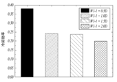
図7は、第1-1幅の大きさに応じた冷却効率を比較して示すグラフであり、図8は、第1-2幅の大きさに応じた冷却効率を比較して示すグラフであり、図9は、第2-2幅の大きさに応じた冷却効率を比較して示すグラフであり、図10は、第2-1幅の大きさに応じた冷却効率を比較して示すグラフであり、図11は、曲線部の中心間隔に応じた冷却効率を比較して示すグラフである。 FIG. 7 is a graph showing a comparison of cooling efficiency depending on the size of the 1-1 width, and FIG. 8 is a graph showing a comparison of cooling efficiency depending on the size of the 1-2 width. 9 is a graph showing a comparison of the cooling efficiency according to the size of the 2-2 width, and FIG. 10 is a graph showing a comparison of the cooling efficiency depending on the size of the 2-1 width. FIG. 11 is a graph showing a comparison of cooling efficiency depending on the center distance of the curved portion.
以下、図7~図11を参照して、本発明の一実施形態に係る冷却ホール1440および冷却ホール1440の形状によるタービンブレード1400の冷却効率について詳しく説明する。
Hereinafter, the cooling efficiency of the
以下のグラフは、噴射比率(Blowing Ratio、以下、BR)が2の場合を条件として測定したものである。噴射比率BRは、タービンブレード1400での単位面積あたりの燃焼ガスの質量流量に対する、冷却ホール1440での単位面積あたりの冷却流体Fの質量流量の比率で定義される。すなわち、タービンブレード1400での燃焼ガスの流速と密度がそれぞれVHとDHであり、冷却ホール1440での冷却流体Fの流速と密度がそれぞれVcとDcである場合、噴射比率BRは、(Vc*Dc)/(VH*DH)で定義される。
The graph below was measured under the condition that the injection ratio (hereinafter referred to as BR) was 2. The injection ratio BR is defined as the ratio of the mass flow rate of the cooling fluid F per unit area in the
また、以下のグラフで示された冷却効率(Area-averaged film cooling effectiveness)は、(T-TH)/(Tc-TH)で定義される。この時、THは、燃焼ガス流動の入口の温度であり、Tcは、冷却流体F流動の出口Oの温度であり、Tは、断熱壁面の温度である。 Furthermore, the cooling efficiency (Area-averaged film cooling effectiveness) shown in the graph below is defined as (T-TH)/(Tc-TH). At this time, TH is the temperature at the inlet of the combustion gas flow, Tc is the temperature at the outlet O of the cooling fluid F flow, and T is the temperature of the adiabatic wall surface.
図7は、入口の内径D、第1-2幅W1-2、第2-1幅W2-1、第2-2幅W2-2が一定の時、第1-1幅W1-1の変化に応じた冷却効率を比較して示す図である。第1-1幅W1-1が入口の内径Dより大きい場合には、冷却効率が0.25より小さく測定された。これに対し、第1-1幅W1-1が入口の内径Dの半分の場合、冷却効率が0.4に近接した値で測定された。すなわち、第1-1幅W1-1が入口の内径Dの以下の場合、冷却効率が極大化されることが分かる。これは、冷却流体Fの、拡張部1441での流動と、凹溝部1442での流動との相互作用によるものである。
Figure 7 shows the change in the 1st-1st width W1-1 when the inner diameter D of the entrance, the 1st-2nd width W1-2, the 2nd-1st width W2-1, and the 2nd-2nd width W2-2 are constant. It is a figure which compares and shows the cooling efficiency according to. When the 1-1 width W1-1 was larger than the inner diameter D of the inlet, the cooling efficiency was measured to be smaller than 0.25. On the other hand, when the 1-1 width W1-1 was half the inner diameter D of the inlet, the cooling efficiency was measured at a value close to 0.4. That is, it can be seen that when the 1-1 width W1-1 is less than or equal to the inner diameter D of the inlet, the cooling efficiency is maximized. This is due to the interaction between the flow of the cooling fluid F in the expanded
図8は、入口の内径D、第1-1幅W1-1、第2-1幅W2-1、第2-2幅W2-2が一定の時、第1-2幅W1-2の変化に応じた冷却効率を比較して示す図である。第1-2幅W1-2が入口の内径Dの3倍または4倍の場合には、冷却効率が0.25より小さく測定された。これに対し、入口の内径Dの5倍の場合には、冷却効率が0.30に近接した値で測定された。したがって、第1-2幅W1-2が入口の内径Dの4倍より大きい場合、冷却効率が増加することが分かる。 Figure 8 shows the change in the 1-2 width W1-2 when the inner diameter D of the entrance, the 1-1 width W1-1, the 2-1 width W2-1, and the 2-2 width W2-2 are constant. It is a figure which compares and shows the cooling efficiency according to. When the first-second width W1-2 was three or four times the inner diameter D of the inlet, the cooling efficiency was measured to be less than 0.25. On the other hand, when the inner diameter D of the inlet was 5 times, the cooling efficiency was measured at a value close to 0.30. Therefore, it can be seen that when the first-second width W1-2 is larger than four times the inner diameter D of the inlet, the cooling efficiency increases.
さらに具体的には、第1-2幅W1-2が入口の内径Dの4.5倍より大きく、5.95より小さい場合、冷却効率が極大化されることが測定された。これは、冷却流体Fの、拡張部1441での流動と、凹溝部1442での流動との相互作用によるものである。
More specifically, it has been determined that when the first-second width W1-2 is larger than 4.5 times the inner diameter D of the inlet and smaller than 5.95, the cooling efficiency is maximized. This is due to the interaction between the flow of the cooling fluid F in the expanded
図9は、入口の内径D、第1-1幅W1-1、第1-2幅W1-2、第2-1幅W2-1が一定の時、第2-2幅W2-2の変化に応じた冷却効率を比較して示す図である。第2-2幅W2-2が入口の内径Dに等しい場合、冷却効率は0.20に近接し、第2-2幅W2-2が入口の内径Dの2倍の場合、冷却効率は0.25に及ばないものと測定された。これに対し、第2-2幅W2-2が入口の内径Dの3倍の場合、冷却効率が0.25を超えて0.30に近接する値で測定された。 Figure 9 shows the change in the 2-2 width W2-2 when the inner diameter D of the entrance, the 1-1 width W1-1, the 1-2 width W1-2, and the 2-1 width W2-1 are constant. It is a figure which compares and shows the cooling efficiency according to. When the 2nd-2nd width W2-2 is equal to the inner diameter D of the inlet, the cooling efficiency is close to 0.20, and when the 2nd-2nd width W2-2 is twice the inner diameter D of the inlet, the cooling efficiency is 0. It was measured to be less than .25. On the other hand, when the 2-2 width W2-2 was three times the inner diameter D of the inlet, the cooling efficiency was measured to be more than 0.25 and close to 0.30.
具体的には、第1-2幅W1-2の長さが第2-2幅W2-2と入口の内径Dとの合計より大きい場合に、冷却効率が極大化された。ただし、第1-2幅W1-2の長さが第2-2幅W2-2と入口の内径Dの2倍との合計以上の場合には、冷却効率が増加しなかった。これは、冷却流体Fの、拡張部1441での流動と、凹溝部1442での流動との相互作用によるものである。
Specifically, when the length of the 1-2 width W1-2 was greater than the sum of the 2-2 width W2-2 and the inner diameter D of the inlet, the cooling efficiency was maximized. However, when the length of the 1-2 width W1-2 was greater than or equal to the sum of the 2-2 width W2-2 and twice the inner diameter D of the inlet, the cooling efficiency did not increase. This is due to the interaction between the flow of the cooling fluid F in the expanded
図10は、入口の内径D、第1-1幅W1-1、第1-2幅W1-2、第2-2幅W2-2が一定の時、第2-1幅W2-1の変化に応じた冷却効率を比較して示す図である。第2-1幅W2-1が入口の内径Dの1.5倍または2.0倍の場合、冷却効率は0.25より小さく測定された。これに対し、第2-1幅W2-1が入口の内径Dに等しい場合、冷却効率が0.25より高く測定された。したがって、第2-1幅W2-1が入口の内径Dの1.5倍より小さい場合、冷却効率が極大化されることが分かる。 Figure 10 shows the change in the 2-1 width W2-1 when the inner diameter D of the entrance, the 1-1 width W1-1, the 1-2 width W1-2, and the 2-2 width W2-2 are constant. It is a figure which compares and shows the cooling efficiency according to. When the 2-1 width W2-1 was 1.5 times or 2.0 times the inner diameter D of the inlet, the cooling efficiency was measured to be less than 0.25. On the other hand, when the 2-1 width W2-1 was equal to the inner diameter D of the inlet, the cooling efficiency was measured to be higher than 0.25. Therefore, it can be seen that when the 2-1 width W2-1 is smaller than 1.5 times the inner diameter D of the inlet, the cooling efficiency is maximized.
これは、冷却流体Fの、拡張部1441での流動と、凹溝部1442での流動との相互作用によるものである。ただし、冷却ホール1440の出口Oに曲線部1443が形成される場合、曲線部1443の曲率半径を考慮して、第2-1幅W2-1は、入口の内径Dの0.5倍よりは大きく形成される。
This is due to the interaction between the flow of the cooling fluid F in the expanded
図11は、第1-2幅W1-2が入口の内径Dの4倍であり、第2-2幅W2-2が入口の内径Dの2倍であり、第1-1幅W1-1が入口の内径Dに等しく、第2-1幅W2-1が入口の内径Dの1.5倍である場合、曲線部1443の間隔変化に応じた冷却効率を比較して示す図である。曲線部1443の間隔Rは、2つの曲線部1443においてそれぞれの曲率中心間の間隔である中心間隔Rを意味する。中心間隔Rの大きさが第2-2幅W2-2に等しい場合、冷却効率は0.25より低く測定された。中心間隔Rの大きさが第2-2幅W2-2と入口の内径Dの0.5倍との合計に等しい場合、冷却効率は0.25に近接して測定された。そして、中心間隔Rが第2-2幅W2-2と入口の内径Dとの合計に等しい場合、冷却効率は0.25より高く測定された。
In FIG. 11, the 1st-2nd width W1-2 is four times the inner diameter D of the entrance, the 2nd-2nd width W2-2 is twice the inner diameter D of the entrance, and the 1st-1st width W1-1 is is equal to the inner diameter D of the inlet, and the 2-1 width W2-1 is 1.5 times the inner diameter D of the inlet. The distance R between the
すなわち、曲線部1443が形成された場合が、曲線部1443が形成されていない場合より冷却効率が高く測定され、曲線部1443の中心間隔Rは、第2-2幅W2-2と入口の内径Dとの合計に等しい場合、高い冷却効率を有することが分かる。これは、曲線部1443が拡張部1441と凹溝部1442で発生しうる渦流の形成を防止したためである。
That is, when the
図12は、本発明の他の実施形態に係るタービンブレードの冷却ホールの出口を示す図である。 FIG. 12 is a diagram showing an outlet of a cooling hole of a turbine blade according to another embodiment of the present invention.
以下、図12を参照して、本発明の他の実施形態に係るタービンブレード1400の冷却ホール1440について説明する。本発明の他の実施形態に係る冷却ホール1440は、凹溝部1442が第1凹溝部1444および第2凹溝部1445を含むことができる。
Hereinafter, with reference to FIG. 12, a
凹溝部1442が第1凹溝部1444および第2凹溝部1445を含む場合、拡張部1441から吐出される冷却流体Fが、第1凹溝部1444から吐出される冷却流体Fによって案内される。そして、第1凹溝部1444から吐出される冷却流体Fは、第2凹溝部1445から吐出される冷却流体Fによって案内される。すなわち、拡張部1441と凹溝部1442から吐出される冷却流体F間の相互作用がさらに緊密に形成可能で、冷却効率がさらに極大化できるというメリットがある。
When the
図12では、冷却ホール1440の凹溝部1442が第1凹溝部1444および第2凹溝部1445で備えられたことを示しているが、場合によって、第n凹溝部から陥没形成された第n+1凹溝部が追加的に形成されてもよい(nは、2以上の自然数)。
Although FIG. 12 shows that the
以上、本発明の一実施例について説明したが、当該技術分野における通常の知識を有する者であれば、特許請求の範囲に記載された本発明の思想を逸脱しない範囲内で、構成要素の付加、変更、削除または追加などによって本発明を多様に修正および変更させることができ、このような修正、変更も本発明の権利範囲内に含まれる。 Although one embodiment of the present invention has been described above, a person having ordinary knowledge in the technical field will be able to add constituent elements without departing from the spirit of the present invention as described in the claims. The present invention can be modified and changed in various ways through changes, deletions, additions, etc., and such modifications and changes are also included within the scope of the rights of the present invention.
1400:タービンブレード
1410:エアホイル
1411:リーディングエッジ
1412:トレーリングエッジ
1413:圧力面
1414:吸入面
1420:プラットフォーム
1430:ルート
1440:冷却ホール
1441:拡張部
1442:凹溝部
1443:曲線部
1444:第1凹溝部
1445:第2凹溝部
W1-1:第1-1幅
W1-2:第1-2幅
W2-1:第2-1幅
W2-2:第2-2幅
R:中心間隔
1400: Turbine blade 1410: Air foil 1411: Leading edge 1412: Trailing edge 1413: Pressure surface 1414: Suction surface 1420: Platform 1430: Root 1440: Cooling hole 1441: Expansion portion 1442: Concave groove portion 1443: Curved portion 1444: First Recessed groove part 1445: Second recessed groove part W1-1: 1st-1st width W1-2: 1st-2nd width W2-1: 2nd-1st width W2-2: 2nd-2nd width R: Center distance
Claims (21)
前記エアホイルにおいて前記冷却流路と外部とを連通させ、入口および出口が形成された冷却ホールとを含み、
前記冷却ホールは、前記出口に、
拡張部と、前記拡張部から前記トレーリングエッジに向かって陥没した凹溝部とが形成され、
前記拡張部は、
前記リーディングエッジと前記トレーリングエッジとを結ぶ直線と並ぶ方向が第1方向の時、前記第1方向への幅である第1-1幅が少なくとも一部の区間で一定に維持されるように形成され、
前記第1-1幅は、前記入口の内径より小さい、タービンブレード。 an air foil having a leading edge and a trailing edge and a cooling passage formed therein through which a cooling fluid flows;
The air foil includes a cooling hole communicating the cooling flow path with the outside and having an inlet and an outlet formed therein;
The cooling hole has the outlet,
an expanded portion and a recessed groove portion depressed from the expanded portion toward the trailing edge ;
The extension part is
When the direction aligned with the straight line connecting the leading edge and the trailing edge is a first direction, a 1-1 width, which is a width in the first direction, is maintained constant in at least a part of the section. formed,
The 1-1 width is smaller than an inner diameter of the inlet .
前記出口の断面積が前記入口の断面積より大きく形成される、請求項1に記載のタービンブレード。 The cooling hole is
The turbine blade according to claim 1, wherein the cross-sectional area of the outlet is larger than the cross-sectional area of the inlet.
略四角形状に形成される、請求項1に記載のタービンブレード。 The extension part is
The turbine blade according to claim 1, wherein the turbine blade is formed in a substantially square shape.
略四角形状に形成される、請求項1に記載のタービンブレード。 The groove portion is
The turbine blade according to claim 1, wherein the turbine blade is formed in a substantially square shape.
前記タービンブレードの回転半径方向が第2方向の時、前記第2方向への幅である第1-2幅が前記入口の前記内径より4倍以上大きく形成される、請求項1から5のいずれか一項に記載のタービンブレード。 The extension part is
Any one of claims 1 to 5, wherein when the rotation radius direction of the turbine blade is in the second direction, a first-second width, which is a width in the second direction, is formed to be four times or more larger than the inner diameter of the inlet. The turbine blade according to item 1.
前記第2方向への幅が第2-2幅であり、
前記第1-2幅は、
前記入口の前記内径と前記第2-2幅との合計より大きく形成される、請求項6に記載のタービンブレード。 The groove portion is
The width in the second direction is a 2-2 width,
The 1st-2nd width is
The turbine blade according to claim 6 , wherein the turbine blade is formed to be larger than the sum of the inner diameter of the inlet and the 2-2 width.
前記第1方向への幅が第2-1幅であり、 The width in the first direction is a 2-1 width,
前記第2-1幅は、前記入口の前記内径の1.5倍より小さく形成される、請求項1から5のいずれか一項に記載のタービンブレード。 The turbine blade according to any one of claims 1 to 5, wherein the 2-1 width is smaller than 1.5 times the inner diameter of the inlet.
前記第1凹溝部は、前記拡張部から前記トレーリングエッジに向かって陥没形成され、
前記第2凹溝部は、前記第1凹溝部から前記トレーリングエッジに向かって陥没形成される、請求項1から5のいずれか一項に記載のタービンブレード。 The groove portion includes a first groove portion and a second groove portion,
The first groove portion is formed to be depressed from the expanded portion toward the trailing edge,
The turbine blade according to any one of claims 1 to 5, wherein the second groove is depressed from the first groove toward the trailing edge.
前記曲線部は、2つが離隔して形成され、
前記それぞれの曲線部間の中心間隔は、前記第2-2幅より大きく形成される、請求項3に記載のタービンブレード。 When the rotation radius direction of the turbine blade is in the second direction, the groove portion has a width in the second direction of a 2-2 width,
The curved portions are formed so that two are spaced apart from each other,
The turbine blade according to claim 3, wherein a center distance between the respective curved portions is formed to be larger than the 2-2 width.
前記エアホイルにおいて前記冷却流路と外部とを連通させ、入口および出口が形成された冷却ホールとを含み、 The air foil includes a cooling hole communicating the cooling flow path with the outside and having an inlet and an outlet formed therein;
前記冷却ホールは、前記出口に、 The cooling hole has the outlet,
拡張部と、前記拡張部から前記トレーリングエッジに向かって陥没した凹溝部とが形成され、 an expanded portion and a recessed groove portion depressed from the expanded portion toward the trailing edge;
前記拡張部と前記凹溝部との境界部分に一定の曲率半径を有する曲線部が形成され、 A curved portion having a constant radius of curvature is formed at a boundary portion between the expanded portion and the groove portion,
タービンブレードの回転半径方向が第2方向の時、前記凹溝部は、前記第2方向への幅が第2-2幅であり、 When the rotation radius direction of the turbine blade is in the second direction, the groove portion has a width in the second direction of a 2-2 width,
前記曲線部は、2つが離隔して形成され、 The curved portions are formed so that two are spaced apart from each other,
前記それぞれの曲線部間の中心間隔は、前記第2-2幅より大きく形成される、タービンブレード。 The turbine blade, wherein the center distance between each of the curved portions is larger than the 2-2 width.
前記タービンロータディスクに配置される複数のタービンブレードと、
固定配置される複数のタービンベーンとを含み、
前記タービンブレードは、
リーディングエッジおよびトレーリングエッジが形成され、内部に冷却流体の流動する冷却流路が形成されたエアホイルと、
前記エアホイルにおいて前記冷却流路と外部とを連通させ、入口および出口が形成された冷却ホールとを含み、
前記冷却ホールは、前記出口に、
拡張部と、前記拡張部から前記トレーリングエッジに向かって陥没した凹溝部とが形成され、
前記拡張部は、
前記リーディングエッジと前記トレーリングエッジとを結ぶ直線と並ぶ方向が第1方向の時、前記第1方向への幅である第1-1幅が少なくとも一部の区間で一定に維持されるように形成され、
前記第1-1幅は、前記入口の内径より小さい、タービン。 a rotatably arranged turbine rotor disk;
a plurality of turbine blades arranged on the turbine rotor disk;
a plurality of fixedly arranged turbine vanes;
The turbine blade is
an air foil having a leading edge and a trailing edge and a cooling passage formed therein through which a cooling fluid flows;
The air foil includes a cooling hole communicating the cooling flow path with the outside and having an inlet and an outlet formed therein;
The cooling hole has the outlet,
an expanded portion and a recessed groove portion depressed from the expanded portion toward the trailing edge ;
The extension part is
When the direction aligned with the straight line connecting the leading edge and the trailing edge is a first direction, a 1-1 width, which is a width in the first direction, is maintained constant in at least a part of the section. formed,
The turbine , wherein the 1-1 width is smaller than an inner diameter of the inlet .
略四角形状に形成される、請求項14に記載のタービン。 The extension part is
The turbine according to claim 14 , wherein the turbine is formed in a substantially square shape.
略四角形状に形成される、請求項14に記載のタービン。 The groove portion is
The turbine according to claim 14 , wherein the turbine is formed in a substantially square shape.
前記タービンブレードの回転半径方向が第2方向の時、前記第2方向への幅である第1-2幅が前記入口の前記内径より大きく形成される、請求項14から17のいずれか一項に記載のタービン。 The extension part is
18. When the rotation radius direction of the turbine blade is in the second direction , a first-second width that is a width in the second direction is formed to be larger than the inner diameter of the inlet. Turbine described in.
前記第2方向への幅が第2-2幅であり、
前記第1-2幅は、
前記入口の前記内径と前記第2-2幅との合計より大きく形成される、請求項18に記載のタービン。 The groove portion is
The width in the second direction is a 2-2 width,
The 1st-2nd width is
The turbine according to claim 18, wherein the turbine is formed to be larger than the sum of the inner diameter of the inlet and the 2-2 width.
前記曲線部は、2つが離隔して形成され、
前記それぞれの曲線部間の中心間隔は、前記第2-2幅より大きく形成される、請求項15に記載のタービン。 When the rotation radius direction of the turbine blade is in the second direction, the groove portion has a width in the second direction of a 2-2 width,
The curved portions are formed so that two are spaced apart from each other,
The turbine according to claim 15 , wherein a center distance between the respective curved portions is larger than the 2-2 width.
前記タービンロータディスクに配置される複数のタービンブレードと、 a plurality of turbine blades arranged on the turbine rotor disk;
固定配置される複数のタービンベーンとを含み、 a plurality of fixedly arranged turbine vanes;
前記タービンブレードは、 The turbine blade is
リーディングエッジおよびトレーリングエッジが形成され、内部に冷却流体の流動する冷却流路が形成されたエアホイルと、 an air foil having a leading edge and a trailing edge and a cooling passage formed therein through which a cooling fluid flows;
前記エアホイルにおいて前記冷却流路と外部とを連通させ、入口および出口が形成された冷却ホールとを含み、 The air foil includes a cooling hole communicating the cooling flow path with the outside and having an inlet and an outlet formed therein;
前記冷却ホールは、前記出口に、 The cooling hole has the outlet,
拡張部と、前記拡張部から前記トレーリングエッジに向かって陥没した凹溝部とが形成され、 an expanded portion and a recessed groove portion depressed from the expanded portion toward the trailing edge;
前記拡張部と前記凹溝部との境界部分に一定の曲率半径を有する曲線部が形成され、 A curved portion having a constant radius of curvature is formed at a boundary portion between the expanded portion and the groove portion,
前記タービンブレードの回転半径方向が第2方向の時、前記凹溝部は、前記第2方向への幅が第2-2幅であり、 When the rotation radius direction of the turbine blade is in the second direction, the groove portion has a width in the second direction of a 2-2 width,
前記曲線部は、2つが離隔して形成され、 The curved portions are formed so that two are spaced apart from each other,
前記それぞれの曲線部間の中心間隔は、前記第2-2幅より大きく形成される、タービン。 The turbine, wherein the center distance between each of the curved portions is larger than the 2-2 width.
Applications Claiming Priority (4)
| Application Number | Priority Date | Filing Date | Title |
|---|---|---|---|
| KR10-2021-0082484 | 2021-06-24 | ||
| KR20210082484 | 2021-06-24 | ||
| KR10-2021-0128309 | 2021-09-28 | ||
| KR1020210128309A KR102623227B1 (en) | 2021-06-24 | 2021-09-28 | turbine blade and turbine including the same |
Publications (2)
| Publication Number | Publication Date |
|---|---|
| JP2023004939A JP2023004939A (en) | 2023-01-17 |
| JP7362997B2 true JP7362997B2 (en) | 2023-10-18 |
Family
ID=82214232
Family Applications (1)
| Application Number | Title | Priority Date | Filing Date |
|---|---|---|---|
| JP2022100584A Active JP7362997B2 (en) | 2021-06-24 | 2022-06-22 | Turbine blades and turbines including the same |
Country Status (3)
| Country | Link |
|---|---|
| US (1) | US11746661B2 (en) |
| EP (1) | EP4108883A1 (en) |
| JP (1) | JP7362997B2 (en) |
Citations (7)
| Publication number | Priority date | Publication date | Assignee | Title |
|---|---|---|---|---|
| JP2008248733A (en) | 2007-03-29 | 2008-10-16 | Mitsubishi Heavy Ind Ltd | High temperature member for gas turbine |
| US20130115103A1 (en) | 2011-11-09 | 2013-05-09 | General Electric Company | Film hole trench |
| JP2013124612A (en) | 2011-12-15 | 2013-06-24 | Ihi Corp | Turbine blade |
| US20140099189A1 (en) | 2012-10-04 | 2014-04-10 | Honeywell International Inc. | Gas turbine engine components with lateral and forward sweep film cooling holes |
| US20160024937A1 (en) | 2013-03-15 | 2016-01-28 | United Technologies Corporation | Multi-lobed cooling hole |
| KR20170020008A (en) | 2015-08-13 | 2017-02-22 | 두산중공업 주식회사 | Blade for turbine |
| DE102018108729A1 (en) | 2018-04-12 | 2019-10-17 | Karlsruher Institut für Technologie | Flow guide, flow-leading component of an internal combustion engine and a turbine blade |
Family Cites Families (69)
| Publication number | Priority date | Publication date | Assignee | Title |
|---|---|---|---|---|
| US4424001A (en) * | 1981-12-04 | 1984-01-03 | Westinghouse Electric Corp. | Tip structure for cooled turbine rotor blade |
| US4684323A (en) * | 1985-12-23 | 1987-08-04 | United Technologies Corporation | Film cooling passages with curved corners |
| US4738588A (en) * | 1985-12-23 | 1988-04-19 | Field Robert E | Film cooling passages with step diffuser |
| GB2227965B (en) * | 1988-10-12 | 1993-02-10 | Rolls Royce Plc | Apparatus for drilling a shaped hole in a workpiece |
| GB8830152D0 (en) * | 1988-12-23 | 1989-09-20 | Rolls Royce Plc | Cooled turbomachinery components |
| US5651662A (en) * | 1992-10-29 | 1997-07-29 | General Electric Company | Film cooled wall |
| US5660525A (en) * | 1992-10-29 | 1997-08-26 | General Electric Company | Film cooled slotted wall |
| US5609779A (en) * | 1996-05-15 | 1997-03-11 | General Electric Company | Laser drilling of non-circular apertures |
| US6287075B1 (en) * | 1997-10-22 | 2001-09-11 | General Electric Company | Spanwise fan diffusion hole airfoil |
| JP3997986B2 (en) * | 2003-12-19 | 2007-10-24 | 株式会社Ihi | Cooling turbine component and cooling turbine blade |
| US7328580B2 (en) * | 2004-06-23 | 2008-02-12 | General Electric Company | Chevron film cooled wall |
| GB0424593D0 (en) * | 2004-11-06 | 2004-12-08 | Rolls Royce Plc | A component having a film cooling arrangement |
| US7186085B2 (en) * | 2004-11-18 | 2007-03-06 | General Electric Company | Multiform film cooling holes |
| US7883320B2 (en) * | 2005-01-24 | 2011-02-08 | United Technologies Corporation | Article having diffuser holes and method of making same |
| US7374401B2 (en) * | 2005-03-01 | 2008-05-20 | General Electric Company | Bell-shaped fan cooling holes for turbine airfoil |
| EP1712739A1 (en) | 2005-04-12 | 2006-10-18 | Siemens Aktiengesellschaft | Component with film cooling hole |
| US7520715B2 (en) * | 2005-07-19 | 2009-04-21 | Pratt & Whitney Canada Corp. | Turbine shroud segment transpiration cooling with individual cast inlet and outlet cavities |
| CA2627958C (en) * | 2005-11-01 | 2011-03-22 | Ihi Corporation | Turbine component |
| US20080003096A1 (en) * | 2006-06-29 | 2008-01-03 | United Technologies Corporation | High coverage cooling hole shape |
| US7553534B2 (en) * | 2006-08-29 | 2009-06-30 | General Electric Company | Film cooled slotted wall and method of making the same |
| US7887294B1 (en) * | 2006-10-13 | 2011-02-15 | Florida Turbine Technologies, Inc. | Turbine airfoil with continuous curved diffusion film holes |
| EP1975372A1 (en) * | 2007-03-28 | 2008-10-01 | Siemens Aktiengesellschaft | Eccentric chamfer at inlet of branches in a flow channel |
| US7621718B1 (en) * | 2007-03-28 | 2009-11-24 | Florida Turbine Technologies, Inc. | Turbine vane with leading edge fillet region impingement cooling |
| US7766609B1 (en) * | 2007-05-24 | 2010-08-03 | Florida Turbine Technologies, Inc. | Turbine vane endwall with float wall heat shield |
| US20090074588A1 (en) * | 2007-09-19 | 2009-03-19 | Siemens Power Generation, Inc. | Airfoil with cooling hole having a flared section |
| US8128366B2 (en) * | 2008-06-06 | 2012-03-06 | United Technologies Corporation | Counter-vortex film cooling hole design |
| US8328517B2 (en) * | 2008-09-16 | 2012-12-11 | Siemens Energy, Inc. | Turbine airfoil cooling system with diffusion film cooling hole |
| US8057181B1 (en) * | 2008-11-07 | 2011-11-15 | Florida Turbine Technologies, Inc. | Multiple expansion film cooling hole for turbine airfoil |
| US7997868B1 (en) * | 2008-11-18 | 2011-08-16 | Florida Turbine Technologies, Inc. | Film cooling hole for turbine airfoil |
| US8245519B1 (en) * | 2008-11-25 | 2012-08-21 | Florida Turbine Technologies, Inc. | Laser shaped film cooling hole |
| US8319146B2 (en) * | 2009-05-05 | 2012-11-27 | General Electric Company | Method and apparatus for laser cutting a trench |
| US20110097191A1 (en) * | 2009-10-28 | 2011-04-28 | General Electric Company | Method and structure for cooling airfoil surfaces using asymmetric chevron film holes |
| US8790083B1 (en) * | 2009-11-17 | 2014-07-29 | Florida Turbine Technologies, Inc. | Turbine airfoil with trailing edge cooling |
| US8529193B2 (en) * | 2009-11-25 | 2013-09-10 | Honeywell International Inc. | Gas turbine engine components with improved film cooling |
| US8857055B2 (en) * | 2010-01-29 | 2014-10-14 | General Electric Company | Process and system for forming shaped air holes |
| US8905713B2 (en) * | 2010-05-28 | 2014-12-09 | General Electric Company | Articles which include chevron film cooling holes, and related processes |
| US8628293B2 (en) * | 2010-06-17 | 2014-01-14 | Honeywell International Inc. | Gas turbine engine components with cooling hole trenches |
| US8672613B2 (en) * | 2010-08-31 | 2014-03-18 | General Electric Company | Components with conformal curved film holes and methods of manufacture |
| US9696035B2 (en) * | 2010-10-29 | 2017-07-04 | General Electric Company | Method of forming a cooling hole by laser drilling |
| US20120167389A1 (en) * | 2011-01-04 | 2012-07-05 | General Electric Company | Method for providing a film cooled article |
| KR101276760B1 (en) | 2011-04-08 | 2013-06-20 | 인하대학교 산학협력단 | The Shape of the film cooling hole for cooling gas turbine blades |
| US9416971B2 (en) * | 2012-02-15 | 2016-08-16 | United Technologies Corporation | Multiple diffusing cooling hole |
| US10422230B2 (en) * | 2012-02-15 | 2019-09-24 | United Technologies Corporation | Cooling hole with curved metering section |
| US9422815B2 (en) * | 2012-02-15 | 2016-08-23 | United Technologies Corporation | Gas turbine engine component with compound cusp cooling configuration |
| US8683813B2 (en) * | 2012-02-15 | 2014-04-01 | United Technologies Corporation | Multi-lobed cooling hole and method of manufacture |
| US9273560B2 (en) * | 2012-02-15 | 2016-03-01 | United Technologies Corporation | Gas turbine engine component with multi-lobed cooling hole |
| US8850828B2 (en) * | 2012-02-15 | 2014-10-07 | United Technologies Corporation | Cooling hole with curved metering section |
| US20130243575A1 (en) * | 2012-03-13 | 2013-09-19 | United Technologies Corporation | Cooling pedestal array |
| US9175569B2 (en) * | 2012-03-30 | 2015-11-03 | General Electric Company | Turbine airfoil trailing edge cooling slots |
| US9017026B2 (en) * | 2012-04-03 | 2015-04-28 | General Electric Company | Turbine airfoil trailing edge cooling slots |
| US20130302177A1 (en) * | 2012-05-08 | 2013-11-14 | Robert Frederick Bergholz, JR. | Turbine airfoil trailing edge bifurcated cooling holes |
| EP2956646B1 (en) * | 2013-02-15 | 2020-10-28 | United Technologies Corporation | Component for a gas turbine engine and corresponding method of forming a cooling hole |
| WO2014186006A2 (en) * | 2013-02-15 | 2014-11-20 | United Technologies Corporation | Cooling hole for a gas turbine engine component |
| US9441488B1 (en) * | 2013-11-07 | 2016-09-13 | United States Of America As Represented By The Secretary Of The Air Force | Film cooling holes for gas turbine airfoils |
| US20160047251A1 (en) * | 2014-08-13 | 2016-02-18 | United Technologies Corporation | Cooling hole having unique meter portion |
| US10233775B2 (en) * | 2014-10-31 | 2019-03-19 | General Electric Company | Engine component for a gas turbine engine |
| DE102015110615A1 (en) * | 2015-07-01 | 2017-01-19 | Rolls-Royce Deutschland Ltd & Co Kg | Guide vane of a gas turbine engine, in particular an aircraft engine |
| EP3192970A1 (en) * | 2016-01-15 | 2017-07-19 | General Electric Technology GmbH | Gas turbine blade and manufacturing method |
| US11021965B2 (en) * | 2016-05-19 | 2021-06-01 | Honeywell International Inc. | Engine components with cooling holes having tailored metering and diffuser portions |
| EP3502418B1 (en) | 2016-08-22 | 2021-05-05 | Doosan Heavy Industries & Construction Co., Ltd. | Gas turbine blade |
| KR101853550B1 (en) | 2016-08-22 | 2018-04-30 | 두산중공업 주식회사 | Gas Turbine Blade |
| US20190085705A1 (en) * | 2017-09-18 | 2019-03-21 | General Electric Company | Component for a turbine engine with a film-hole |
| KR101980787B1 (en) | 2017-09-29 | 2019-08-28 | 두산중공업 주식회사 | Blade airfoil, turbine and gas turbine comprising the same |
| KR101997979B1 (en) | 2017-10-17 | 2019-07-08 | 두산중공업 주식회사 | Blade airfoil, turbine and gas turbine comprising the same |
| KR20190122918A (en) | 2018-04-18 | 2019-10-31 | 두산중공업 주식회사 | Double angled laidback fan shaped film cooling hole structure |
| KR102117430B1 (en) | 2018-11-14 | 2020-06-01 | 두산중공업 주식회사 | Structure for Improving Cooling Performance of Blade and Blades and Gas Turbines having the same |
| US11015456B2 (en) * | 2019-05-20 | 2021-05-25 | Power Systems Mfg., Llc | Near wall leading edge cooling channel for airfoil |
| US11459898B2 (en) * | 2020-07-19 | 2022-10-04 | Raytheon Technologies Corporation | Airfoil cooling holes |
| KR20200129074A (en) | 2020-11-06 | 2020-11-17 | 두산중공업 주식회사 | Enhanced film cooling system |
-
2022
- 2022-06-22 JP JP2022100584A patent/JP7362997B2/en active Active
- 2022-06-22 US US17/846,077 patent/US11746661B2/en active Active
- 2022-06-22 EP EP22180509.6A patent/EP4108883A1/en active Pending
Patent Citations (7)
| Publication number | Priority date | Publication date | Assignee | Title |
|---|---|---|---|---|
| JP2008248733A (en) | 2007-03-29 | 2008-10-16 | Mitsubishi Heavy Ind Ltd | High temperature member for gas turbine |
| US20130115103A1 (en) | 2011-11-09 | 2013-05-09 | General Electric Company | Film hole trench |
| JP2013124612A (en) | 2011-12-15 | 2013-06-24 | Ihi Corp | Turbine blade |
| US20140099189A1 (en) | 2012-10-04 | 2014-04-10 | Honeywell International Inc. | Gas turbine engine components with lateral and forward sweep film cooling holes |
| US20160024937A1 (en) | 2013-03-15 | 2016-01-28 | United Technologies Corporation | Multi-lobed cooling hole |
| KR20170020008A (en) | 2015-08-13 | 2017-02-22 | 두산중공업 주식회사 | Blade for turbine |
| DE102018108729A1 (en) | 2018-04-12 | 2019-10-17 | Karlsruher Institut für Technologie | Flow guide, flow-leading component of an internal combustion engine and a turbine blade |
Also Published As
| Publication number | Publication date |
|---|---|
| JP2023004939A (en) | 2023-01-17 |
| US20220412217A1 (en) | 2022-12-29 |
| EP4108883A1 (en) | 2022-12-28 |
| US11746661B2 (en) | 2023-09-05 |
Similar Documents
| Publication | Publication Date | Title |
|---|---|---|
| JP2005535860A (en) | Orbital combustion nozzle engine | |
| JP2017141828A (en) | Component for cooling gas turbine engine | |
| KR102161765B1 (en) | Airfoil for turbine, turbine including the same | |
| JP7362997B2 (en) | Turbine blades and turbines including the same | |
| JP2014506978A (en) | gas turbine | |
| US11448074B2 (en) | Turbine airfoil and turbine including same | |
| KR102623227B1 (en) | turbine blade and turbine including the same | |
| Virdi et al. | Design and fabrication of major components of turbojet engine | |
| KR102158298B1 (en) | Turbine blade, turbine including the same | |
| KR102584495B1 (en) | Turbine blade and turbine including the same | |
| KR102466386B1 (en) | Turbine blade, turbine including the same | |
| US20230128531A1 (en) | Turbine airfoil, turbine, and gas turbine including same | |
| US11933192B2 (en) | Turbine vane, and turbine and gas turbine including same | |
| EP4299985A1 (en) | Jet nozzle | |
| KR102156428B1 (en) | Airfoil for turbine, turbine including the same | |
| KR20220037186A (en) | Turbine vane, turbine including the same | |
| US20240003544A1 (en) | Jet nozzle, combustor, and gas turbine including same | |
| KR102510535B1 (en) | Ring segment and turbo-machine comprising the same | |
| KR102155797B1 (en) | Turbine blade, turbine including the same | |
| US20240003546A1 (en) | Jet nozzle, combustor, and gas turbine including same | |
| KR102162970B1 (en) | Airfoil for turbine, turbine including the same | |
| KR20230119954A (en) | Turbine vane, turbine including the same | |
| JP2010084704A (en) | Combustor connection structure and gas turbine | |
| KR101984397B1 (en) | Rotor, turbine and gas turbine comprising the same | |
| KR20230081267A (en) | Turbine blade, turbine and gas turbine including the same |
Legal Events
| Date | Code | Title | Description |
|---|---|---|---|
| A621 | Written request for application examination |
Free format text: JAPANESE INTERMEDIATE CODE: A621 Effective date: 20220622 |
|
| A977 | Report on retrieval |
Free format text: JAPANESE INTERMEDIATE CODE: A971007 Effective date: 20230420 |
|
| A131 | Notification of reasons for refusal |
Free format text: JAPANESE INTERMEDIATE CODE: A131 Effective date: 20230425 |
|
| A521 | Request for written amendment filed |
Free format text: JAPANESE INTERMEDIATE CODE: A523 Effective date: 20230530 |
|
| TRDD | Decision of grant or rejection written | ||
| A01 | Written decision to grant a patent or to grant a registration (utility model) |
Free format text: JAPANESE INTERMEDIATE CODE: A01 Effective date: 20230905 |
|
| A61 | First payment of annual fees (during grant procedure) |
Free format text: JAPANESE INTERMEDIATE CODE: A61 Effective date: 20230912 |
|
| R150 | Certificate of patent or registration of utility model |
Ref document number: 7362997 Country of ref document: JP Free format text: JAPANESE INTERMEDIATE CODE: R150 |