JP7360001B2 - Manufacturing method for machine tools and cutting products - Google Patents
Manufacturing method for machine tools and cutting products Download PDFInfo
- Publication number
- JP7360001B2 JP7360001B2 JP2019102302A JP2019102302A JP7360001B2 JP 7360001 B2 JP7360001 B2 JP 7360001B2 JP 2019102302 A JP2019102302 A JP 2019102302A JP 2019102302 A JP2019102302 A JP 2019102302A JP 7360001 B2 JP7360001 B2 JP 7360001B2
- Authority
- JP
- Japan
- Prior art keywords
- hole
- tool
- cutting tool
- region
- cutting
- Prior art date
- Legal status (The legal status is an assumption and is not a legal conclusion. Google has not performed a legal analysis and makes no representation as to the accuracy of the status listed.)
- Active
Links
Images


Landscapes
- Gripping On Spindles (AREA)
Description
本態様は、一般的には、切削加工において用いられる機械工具に関する。 TECHNICAL FIELD This aspect generally relates to mechanical tools used in cutting operations.
金属などの被削材を切削加工する際に用いられる機械工具として、被削材のサイズに応じて切削工具の突き出し量を調整できる機械工具が知られている。例えば、特許文献1には、このような機械工具を構成する工具ホルダが開示されている。特許文献1に記載の工具ホルダは、工具を装着するホルダシャンクの内部に、ホルダ全長にわたって貫通する給液孔を設け、その給液孔に設けたネジ部にストッパボルトを取り付け、このストッパボルトと工具を当接させて工具の突き出し量を調節する。ストッパボルトは、給液孔の軸線方向に配列される操作部材などで構成される。
BACKGROUND ART As a mechanical tool used when cutting a work material such as metal, a mechanical tool that can adjust the amount of protrusion of the cutting tool according to the size of the work material is known. For example,
特許文献1に記載の工具ホルダでは、ホルダシャンクの先端側に操作部材を位置させた場合に、ホルダシャンクのうち工作機械に把持される部分の剛性が低下してつぶれる恐れがある。
In the tool holder described in
一態様に基づく機械工具は、切削工具、筒部材及び位置決め部材を有する。筒部材は、第1端から第2端にかけて延びる。位置決め部材は、第3端から第4端にかけて延びた柱状である。筒部材は、第1部分、第2部分及び貫通孔を有する。第2部分は、第1部分よりも第2端の側に位置し、第1部分よりも外径が小さい。貫通孔は、第1端から第2端にかけて貫通し、第1端の側に切削工具の一部が挿入されている。貫通孔は、第1貫通孔及び第2貫通孔を有する。第2貫通孔は、第1貫通孔よりも第2端の側に位置するとともに、第2部分の内側にのみ位置し、第1貫通孔よりも内径が大きい。位置決め部材は、第1領域及び第2領域を有する。第2領域は、第1領域よりも第4端の側に位置し、第1領域よりも外径が大きい。第3端は、切削工具の後端に当接している。
A mechanical tool according to one embodiment includes a cutting tool, a cylindrical member, and a positioning member. The cylindrical member extends from the first end to the second end. The positioning member has a columnar shape extending from the third end to the fourth end. The cylindrical member has a first portion, a second portion, and a through hole. The second portion is located closer to the second end than the first portion, and has a smaller outer diameter than the first portion. The through hole penetrates from the first end to the second end, and a part of the cutting tool is inserted into the first end side. The through hole has a first through hole and a second through hole. The second through hole is located closer to the second end than the first through hole , is located only inside the second portion , and has a larger inner diameter than the first through hole. The positioning member has a first region and a second region. The second region is located closer to the fourth end than the first region, and has a larger outer diameter than the first region. The third end abuts the rear end of the cutting tool.
第2貫通孔は、第1部分よりも第2端の側に位置する。筒部材は、ネジ溝を更に有する。ネジ溝は、第2貫通孔の内壁面に位置する。位置決め部材は、ネジ山を更に有する。ネジ山は、第2領域の外周面に位置する。ネジ山とネジ溝とが螺合している。位置決め部材は、前記筒部材の延びた方向に沿って動かすことが可能であって、切削工具の突き出し量を調節できる。 The second through hole is located closer to the second end than the first portion. The cylindrical member further has a thread groove. The thread groove is located on the inner wall surface of the second through hole. The positioning member further includes a thread. The thread is located on the outer peripheral surface of the second region. The screw thread and the screw groove are screwed together. The positioning member can be moved along the direction in which the cylindrical member extends, and can adjust the amount of protrusion of the cutting tool.
上記態様によれば、切削工具を安定して把持し易く、また、工作機械に把持される部分がつぶれにくい。 According to the above aspect, it is easy to stably hold the cutting tool, and the portion held by the machine tool is less likely to be crushed.
<機械工具>
以下、実施形態の機械工具1について、図面を用いて詳細に説明する。但し、以下で参照する各図は、説明の便宜上、実施形態を説明する上で必要な主要部材のみを簡略化して示したものである。したがって、機械工具1は、参照する各図に示されていない任意の構成部材を備え得る。また、各図中の部材の寸法は、実際の構成部材の寸法及び各部材の寸法比率などを忠実に表したものではない。
<Machine tools>
Hereinafter, a
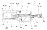
機械工具1は、図1~図8に示す一例のように、切削工具3、筒部材5及び位置決め部材7を有してもよい。
The
切削工具3は、被削材に接触して切削加工を行うことが可能である。切削工具3は、インサートタイプでもよく、また、ソリッドタイプでもよい。インサートタイプは、ホルダ及びこのホルダに装着される切削インサートのように、複数の部材で構成された工具である。ソリッドタイプは、全体が1つの部材で一体的に形成された工具である。切削工具3は、例えば、ドリル、転削工具及び旋削工具などのいずれでもよく、特に限定されない。
The
切削工具3は、図1~図6に示す一例のように、インサートタイプのドリルでもよい。より具体的には、切削工具3は、柱状のホルダ9と、このホルダ9の先端側に装着された切削インサート11(以下、「インサート11」ということがある。)と、を有する先端交換ドリルでもよい。そして、切削工具3は、回転軸O1を有してもよい。切削工具3は、被削材を切削する際に回転軸O1の周りで回転可能でもよい。
The
ホルダ9は、特定の大きさに限定されない。例えば、ホルダ9の外径Dは、3~60mm程度に設定されてもよい。また、回転軸O1に沿った方向におけるホルダ9の長さLは、0.5D~20D程度に設定されてもよい。ホルダ9の材質としては、例えば、鋼及び鋳鉄などが挙げられる。
The
インサート11は、第1切刃13を有してもよい。第1切刃13は、切削加工において被削材を切削するために用いることが可能である。インサート11は、第1切刃13がホルダ9から外方に突出するようにホルダ9に装着されてもよい。インサート11の材質としては、例えば、超硬合金、サーメット及びセラミックスなどの無機材料が挙げられる。
The
筒部材5は、切削工具3を把持する部材(把持部材)として機能することが可能である。筒部材5は、第1端5aから第2端5bにかけて延びた筒状の部材でもよい。一般的に、第1端5aは先端、第2端5bは後端とも呼ばれる。また、筒部材5は、円筒状でもよいが、これに限定されない。
The
筒部材5は、中心軸O2を有してもよい。中心軸O2は、第1端5aの中心及び第2端5bの中心を通る軸である。筒部材5は、被削材を切削する際に中心軸O2の周りで回転可能でもよい。中心軸O2は、切削工具3の回転軸O1と一致してもよい。
The
筒部材5としては、例えば、面取りに用いるアタッチメント(面取りアタッチメント)及びアーバなどが挙げられる。図1~図8においては、筒部材5が面取りアタッチメントである例を示しているが、これに限定されない。筒部材5は、第1端5aの側に位置する第2切刃15を有してもよい。第2切刃15は、面取りに用いることが可能である。第2切刃15は、第1端5aの側において外方に突出するように位置してもよい。
Examples of the
筒部材5は、特定の大きさに限定されない。例えば、筒部材5の外径は、10~100mm程度に設定されてもよい。中心軸O2に沿った方向における筒部材5の長さは、20~300mm程度に設定されてもよい。筒部材5の材質としては、例えば、クロムモリブデン鋼及びニッケルクロムモリブデン鋼などが挙げられる。
The
筒部材5は、図6~図8に示す一例のように、第1部分17、第2部分19及び貫通孔21を有してもよい。第1部分17は、切削工具3を把持する部分として機能することが可能である。第2部分19は、工作機械に把持される部分として機能することが可能である。第2部分19は、第1部分17よりも第2端5bの側に位置してもよい。また、第2部分19は、第1部分17よりも外径が小さくてもよい。言い換えれば、第1部分17の外径D1は、第2部分19の外径D2よりも大きくてもよい。
The
貫通孔21は、第1端5aから第2端5bにかけて貫通してもよく、また、第1端5aの側に切削工具3の一部が挿入されてもよい。切削工具3は、第1切刃13の少なくとも一部が第1端5aの側から突出するように貫通孔21に挿入されてもよい。
The through
貫通孔21は、第1貫通孔23及び第2貫通孔25を有してもよい。第2貫通孔25は、第1貫通孔23よりも第2端5bの側に位置してもよい。また、第2貫通孔25は、第1貫通孔23よりも内径が大きくてもよい。言い換えれば、第1貫通孔23の内径D3は、第2貫通孔25の内径D4よりも小さくてもよい。
The through
位置決め部材7は、切削工具3の突き出し量を調整する部材として機能することが可能である。位置決め部材7は、第3端7aから第4端7bにかけて延びた柱状の部材でもよい。図6に示す一例のように、位置決め部材7が延びる方向、すなわち第3端7aから第4端7bに向かう方向が、筒部材5が延びる方向、すなわち第1端5aから第2端5bに向かう方向と一致してもよい。また、第3端7aは、切削工具3(ホルダ9)の後端に接触することが可能である。位置決め部材7は、円柱状でもよいが、これに限定されない。位置決め部材7の材質としては、例えば、クロムモリブデン鋼及びニッケルクロムモリブデン鋼などが挙げられる。
The positioning
位置決め部材7は、第1領域27及び第2領域29を有してもよい。第2領域29は、第1領域27よりも第4端7bの側に位置してもよい。また、第2領域29は、第1領域27よりも外径が大きくてもよい。言い換えれば、第1領域27の外径D5は、第2領域29の外径D6よりも小さくてもよい。
The positioning
ここで、図7に示す一例のように、第2貫通孔25は、第1部分17よりも第2端5bの側に位置してもよい。言い換えれば、第2貫通孔25は、第2部分19の内側にのみ位置してもよい。また、筒部材5は、ネジ溝31を更に有してもよい。ネジ溝31は、第2貫通孔25の内壁面に位置してもよい。位置決め部材7は、ネジ山33を更に有してもよい。言い換えれば、位置決め部材7は、ネジでもよい。ネジ山33は、第2領域29の外周面に位置してもよい。そして、ネジ山33とネジ溝31とが螺合してもよい。
Here, as in the example shown in FIG. 7, the second through
上記の場合には、切削工具3を安定して把持し易く、また、工作機械に把持される部分がつぶれにくい。すなわち、第1部分17の外径D1が第2部分19の外径D2よりも大きいことから、切削工具3を把持する部分である第1部分17の肉厚が厚く、切削工具3を安定して把持し易い。また、位置決め部材7における相対的に外径が大きい第2領域29が、工作機械に把持される部分である第2部分19の内側に位置することから、第2部分19の剛性を維持することができ、第2部分19がつぶれにくい。ネジ山33とネジ溝31とが螺合することから、位置決め部材7を回すと、位置決め部材7を筒部材5の延びた方向に沿って動かすことができ、筒部材5からの切削工具3の突き出し量を調整できる。
In the above case, it is easy to stably hold the
なお、第1貫通孔23の一部は、第2部分19の内側に位置してもよい。第1貫通孔23の内径D3は、一定でもよく、また、変化してもよい。
Note that a portion of the first through
第2貫通孔25は、第2端5bにおいて開口してもよい。この場合には、位置決め部材7を第2端5bの側から貫通孔21に挿入できる。その結果、第1部分17を1つの部材で一体的に形成することが可能となる。
The second through
第2領域29は、第4端7bを含んでもよい。位置決め部材7は、第4端7bに位置する第1凹部35を更に有してもよい。第1凹部35は、位置決め部材7を回すための部位として機能することが可能である。第1凹部35の形状としては、例えば、溝状及び穴状などが挙げられる。これらの点は、後述する第2凹部においても同様である。位置決め部材7が第1凹部35を有する場合には、第2端5bの側から第1凹部35を介して位置決め部材7を回すことが可能となる。したがって、切削工具3を筒部材5で把持した状態で切削工具3の突き出し量を調整できる。
The
位置決め部材7の延びた方向において、第1凹部35の幅W1、及び、第2領域29の幅W2は、それぞれ特定の値に限定されない。幅W1が、幅W2の半分以下でもよい。この場合には、第2領域29によって安定して第2部分19を支持できることから、第2部分19がつぶれにくい。
In the direction in which the
位置決め部材7は、第3端7aに位置する第2凹部37を更に有してもよい。この場合には、第1端5aの側から第2凹部37を介して位置決め部材7を回すことが可能となる。
The positioning
第2部分19の外径D2は、一定でもよく、また、変化してもよい。第2部分19の外径D2が一定の場合には、第2部分19の肉厚を確保し易く、第2部分19がつぶれにくい。なお、第2部分19と同様に、第1部分17の外径D1は、一定でもよく、また、変化してもよい。
The outer diameter D2 of the
筒部材5は、図6に示す一例のように、筒部材5の外周面から貫通孔21まで貫通する孔39を有してもよい。孔39は、ネジ溝を有してもよい。孔39は、切削工具3を筒部材5に固定するために用いることが可能である。例えば、固定ネジ41を孔39に挿入して切削工具3を筒部材5にネジ止め固定してもよい。このとき、固定ネジ41と切削工具3との間に弾性部材43を挟んでもよい。弾性部材43としては、例えば、金属または樹脂からなるバネ、樹脂シートなどが挙げられる。なお、切削工具3を筒部材5に固定する方法は、上記のネジ止め固定に限定されない。
The
筒部材5は、第3部分45を有してもよい。第3部分45は、第1部分17による切削工具3の把持を補助する部分として機能することが可能である。第3部分45は、第1部分17よりも第1端5aの側に位置してもよい。また、第3部分45の外径は、第1端5aから離れるにしたがって大きくなってもよい。上記の第2切刃15は、第3部分45に位置してもよい。より具体的には、筒部材5は、第3部分45に装着されたチップ47を有してもよく、このチップ47が第2切刃15を有してもよい。
The
<切削加工物の製造方法>
次に、実施形態の切削加工物101の製造方法について図面を用いて説明する。
<Method for manufacturing cut workpieces>
Next, a method for manufacturing the
切削加工物101は、被削材103を切削加工することによって作製される。実施形態における切削加工物101の製造方法は、以下の工程を備えてもよい。すなわち、
(1)上記の実施形態に代表される機械工具1を回転させる工程と、
(2)回転している機械工具1における切削工具3を被削材103に接触させる工程と、
(3)切削工具3を被削材103から離す工程と、
を備えてもよい。
The
(1) A step of rotating the
(2) a step of bringing the
(3) a step of separating the
may be provided.
具体的に説明すると、(1)の工程では、図9に示す一例のように、中心軸O2(回転軸O1)を中心にY1方向に機械工具1を回転させ、Y2方向に機械工具1を移動させることによって、切削工具3と被削材103とを相対的に近付けてもよい。また、(1)の工程は、例えば、機械工具1が取り付けられた工作機械のテーブルの上に被削材103を固定し、機械工具1を回転させた状態で被削材103に近付けることにより行ってもよい。
To explain more specifically, in the step (1), as shown in the example shown in FIG. By moving, the
(2)の工程では、図10に示す一例のように、切削工具3におけるインサート11の第1切刃13を、被削材103の表面の所望の位置に接触させて、被削材103に加工穴(貫通孔)105を形成してもよい。 In the step (2), as shown in the example shown in FIG. A processed hole (through hole) 105 may be formed.
(3)の工程では、図11に示す一例のように、切削工具3をY3方向に移動させることによって被削材103から離してもよい。
In the step (3), as in the example shown in FIG. 11, the
実施形態の切削加工物101の製造方法によれば、切削工具3を安定して把持し易く、また、工作機械に把持される部分がつぶれにくい機械工具1を用いることから、精度が高い加工穴105を有する切削加工物101を得ることができる。
According to the method for manufacturing the
なお、実施形態の製造方法における切削加工では、それぞれの工程において、機械工具1を動かすことによって、切削工具3を被削材103に接触させる、あるいは、切削工具3を被削材103から離しているが、当然ながらこのような形態に限定されない。
In addition, in the cutting process in the manufacturing method of the embodiment, in each step, the
例えば、(1)の工程において、被削材103を切削工具3に近付けてもよい。同様に、(3)の工程において、被削材103を切削工具3から遠ざけてもよい。切削加工を継続する場合には、切削工具3を回転させた状態を維持して、被削材103の異なる箇所にインサート11の第1切刃13を接触させる工程を繰り返せばよい。
For example, in the step (1), the
なお、被削材103の材質の代表例としては、炭素鋼、合金鋼、ステンレス、鋳鉄及び非鉄金属などが挙げられる。
Note that typical examples of the material of the
以上、実施形態の機械工具1及び切削加工物101の製造方法について例示したが、本開示は上記の実施形態に限定されず、本開示の要旨を逸脱しない限り任意のものとすることができることはいうまでもない。
Although the method for manufacturing the
例えば、上記の実施形態では、切削工具3がドリルであるが、これに代えて、切削工具3を、例えば、旋削工具などにすることができる。この場合には、切削加工物101の製造方法における(1)の工程では、被削材103を回転させればよい。
For example, in the above embodiment, the
1・・・機械工具
3・・・切削工具
5・・・筒部材
5a・・第1端
5b・・第2端
7・・・位置決め部材
7a・・第3端
7b・・第4端
9・・・ホルダ
11・・・切削インサート(インサート)
13・・・第1切刃
15・・・第2切刃
17・・・第1部分
19・・・第2部分
21・・・貫通孔
23・・・第1貫通孔
25・・・第2貫通孔
27・・・第1領域
29・・・第2領域
31・・・ネジ溝
33・・・ネジ山
35・・・第1凹部
37・・・第2凹部
39・・・孔
41・・・固定ネジ
43・・・弾性部材
45・・・第3部分
47・・・チップ
101・・・切削加工物
103・・・被削材
105・・・加工穴
O1・・・回転軸
O2・・・中心軸
D1・・・外径
D2・・・外径
D3・・・内径
D4・・・内径
D5・・・外径
D6・・・外径
W1・・・幅
W2・・・幅
1...
13... First cutting
Claims (6)
第1端から第2端にかけて延びた筒部材と、
第3端から第4端にかけて延びた柱状の位置決め部材と、を有し、
前記筒部材は、
第1部分と、
前記第1部分よりも前記第2端の側に位置し、前記第1部分よりも外径が小さい第2部分と、
前記第1端から前記第2端にかけて貫通し、前記第1端の側に前記切削工具の一部が挿入されている貫通孔と、を有し、
前記貫通孔は、
第1貫通孔と、
前記第1貫通孔よりも前記第2端の側に位置し、前記第1貫通孔よりも内径が大きい第2貫通孔と、を有し、
前記位置決め部材は、
第1領域と、
前記第1領域よりも前記第4端の側に位置し、前記第1領域よりも外径が大きい第2領域と、を有し、
前記第3端は、前記切削工具の後端に当接し、
前記第2貫通孔は、前記第1部分よりも前記第2端の側に位置するとともに、前記第2部分の内側にのみ位置し、
前記筒部材は、前記第2貫通孔の内壁面に位置するネジ溝を更に有し、
前記位置決め部材は、前記第2領域の外周面に位置するネジ山を更に有し、
前記ネジ山と前記ネジ溝とが螺合し、
前記位置決め部材は、前記筒部材の延びた方向に沿って動かすことが可能であって、前記切削工具の突き出し量を調整できる、機械工具。 cutting tools and
a cylindrical member extending from the first end to the second end;
a columnar positioning member extending from the third end to the fourth end,
The cylindrical member is
The first part and
a second portion located closer to the second end than the first portion and having a smaller outer diameter than the first portion;
a through hole that extends from the first end to the second end and into which a part of the cutting tool is inserted on the first end side;
The through hole is
a first through hole;
a second through hole located closer to the second end than the first through hole, and having a larger inner diameter than the first through hole;
The positioning member is
a first area;
a second region located closer to the fourth end than the first region and having a larger outer diameter than the first region;
the third end abuts a rear end of the cutting tool;
The second through hole is located closer to the second end than the first portion, and is located only inside the second portion,
The cylindrical member further has a thread groove located on the inner wall surface of the second through hole,
The positioning member further includes a screw thread located on the outer peripheral surface of the second region,
the screw thread and the screw groove are screwed together;
A mechanical tool, wherein the positioning member is movable along the extending direction of the cylindrical member to adjust the amount of protrusion of the cutting tool.
前記位置決め部材は、前記第4端に位置する第1凹部を更に有する、請求項1又は2に記載の機械工具。 the second region includes the fourth end,
The machine tool according to claim 1 or 2, wherein the positioning member further has a first recess located at the fourth end.
前記機械工具における前記切削工具を前記被削材に接触させる工程と、
前記切削工具を前記被削材から離す工程と、を備えた切削加工物の製造方法。
A step of rotating at least one of the machine tool and the workpiece according to any one of claims 1 to 5;
a step of bringing the cutting tool in the mechanical tool into contact with the workpiece;
A method for manufacturing a cut workpiece, comprising the step of separating the cutting tool from the workpiece.
Priority Applications (1)
| Application Number | Priority Date | Filing Date | Title |
|---|---|---|---|
| JP2019102302A JP7360001B2 (en) | 2019-05-31 | 2019-05-31 | Manufacturing method for machine tools and cutting products |
Applications Claiming Priority (1)
| Application Number | Priority Date | Filing Date | Title |
|---|---|---|---|
| JP2019102302A JP7360001B2 (en) | 2019-05-31 | 2019-05-31 | Manufacturing method for machine tools and cutting products |
Publications (2)
| Publication Number | Publication Date |
|---|---|
| JP2020196062A JP2020196062A (en) | 2020-12-10 |
| JP7360001B2 true JP7360001B2 (en) | 2023-10-12 |
Family
ID=73648311
Family Applications (1)
| Application Number | Title | Priority Date | Filing Date |
|---|---|---|---|
| JP2019102302A Active JP7360001B2 (en) | 2019-05-31 | 2019-05-31 | Manufacturing method for machine tools and cutting products |
Country Status (1)
| Country | Link |
|---|---|
| JP (1) | JP7360001B2 (en) |
Family Cites Families (4)
| Publication number | Priority date | Publication date | Assignee | Title |
|---|---|---|---|---|
| JPS60131305U (en) * | 1984-02-14 | 1985-09-03 | トヨタ自動車株式会社 | tool mounting device |
| JPS6120206U (en) * | 1984-07-12 | 1986-02-05 | 株式会社不二越 | rotary tool holder |
| US5348319A (en) * | 1993-06-25 | 1994-09-20 | Ryobi Motor Products Corporation | Chuck utilizing cam |
| JP2949038B2 (en) * | 1994-08-02 | 1999-09-13 | 株式会社エムエスティコーポレーション | Liquid supply cap for tool holder |
-
2019
- 2019-05-31 JP JP2019102302A patent/JP7360001B2/en active Active
Also Published As
| Publication number | Publication date |
|---|---|
| JP2020196062A (en) | 2020-12-10 |
Similar Documents
| Publication | Publication Date | Title |
|---|---|---|
| CN109434395B (en) | Method for processing high-precision deep long hole thin-wall sleeve type part | |
| US4668138A (en) | Tool holder | |
| US5024563A (en) | Cutting apparatus | |
| KR102358913B1 (en) | Hole processing tool and guide pad adjustment mechanism therefor | |
| US9770770B2 (en) | Rigid universal cartridge for holding system | |
| JP4436829B2 (en) | Indexable cutting tool | |
| WO2017163576A1 (en) | Method for reusing end mill | |
| JP7360001B2 (en) | Manufacturing method for machine tools and cutting products | |
| JP2009061587A (en) | Insert | |
| JP2006263828A (en) | Cutting tool | |
| JP4481224B2 (en) | Tool gripping chuck | |
| JP4872534B2 (en) | Cutting tools | |
| JP5689303B2 (en) | Lathe chuck | |
| JP2016198857A (en) | Tool positioning jig | |
| JP2005161434A (en) | Drill | |
| JP7074348B2 (en) | Reamer | |
| KR100296445B1 (en) | Indexable boring tool for cutting an internal surface of a small size's hole | |
| KR20220011179A (en) | Interchangeable head cutting tools, cutting heads, and tool bodies | |
| JP2013198967A (en) | Clamp mechanism of cutting member, and cutting edge replacing type cutting tool using the same | |
| JP2005022003A (en) | Rotary cutting tool | |
| JP2008296326A (en) | Cutting holder and cutware | |
| JP2009154220A (en) | Cutware | |
| JP2009291858A (en) | Boring tool | |
| JP2007245295A (en) | Insert detachable-type drill | |
| US20060232020A1 (en) | Collet liner |
Legal Events
| Date | Code | Title | Description |
|---|---|---|---|
| A621 | Written request for application examination |
Free format text: JAPANESE INTERMEDIATE CODE: A621 Effective date: 20211210 |
|
| A977 | Report on retrieval |
Free format text: JAPANESE INTERMEDIATE CODE: A971007 Effective date: 20221019 |
|
| A131 | Notification of reasons for refusal |
Free format text: JAPANESE INTERMEDIATE CODE: A131 Effective date: 20221025 |
|
| A521 | Request for written amendment filed |
Free format text: JAPANESE INTERMEDIATE CODE: A523 Effective date: 20221222 |
|
| A131 | Notification of reasons for refusal |
Free format text: JAPANESE INTERMEDIATE CODE: A131 Effective date: 20230418 |
|
| A521 | Request for written amendment filed |
Free format text: JAPANESE INTERMEDIATE CODE: A523 Effective date: 20230601 |
|
| TRDD | Decision of grant or rejection written | ||
| A01 | Written decision to grant a patent or to grant a registration (utility model) |
Free format text: JAPANESE INTERMEDIATE CODE: A01 Effective date: 20230830 |
|
| A61 | First payment of annual fees (during grant procedure) |
Free format text: JAPANESE INTERMEDIATE CODE: A61 Effective date: 20230905 |
|
| R150 | Certificate of patent or registration of utility model |
Ref document number: 7360001 Country of ref document: JP Free format text: JAPANESE INTERMEDIATE CODE: R150 |