JP7357488B2 - Exposure device and article manufacturing method - Google Patents
Exposure device and article manufacturing method Download PDFInfo
- Publication number
- JP7357488B2 JP7357488B2 JP2019161464A JP2019161464A JP7357488B2 JP 7357488 B2 JP7357488 B2 JP 7357488B2 JP 2019161464 A JP2019161464 A JP 2019161464A JP 2019161464 A JP2019161464 A JP 2019161464A JP 7357488 B2 JP7357488 B2 JP 7357488B2
- Authority
- JP
- Japan
- Prior art keywords
- concave mirror
- substrate
- optical system
- exposure apparatus
- mask
- Prior art date
- Legal status (The legal status is an assumption and is not a legal conclusion. Google has not performed a legal analysis and makes no representation as to the accuracy of the status listed.)
- Active
Links
Images


Classifications
-
- G—PHYSICS
- G03—PHOTOGRAPHY; CINEMATOGRAPHY; ANALOGOUS TECHNIQUES USING WAVES OTHER THAN OPTICAL WAVES; ELECTROGRAPHY; HOLOGRAPHY
- G03F—PHOTOMECHANICAL PRODUCTION OF TEXTURED OR PATTERNED SURFACES, e.g. FOR PRINTING, FOR PROCESSING OF SEMICONDUCTOR DEVICES; MATERIALS THEREFOR; ORIGINALS THEREFOR; APPARATUS SPECIALLY ADAPTED THEREFOR
- G03F7/00—Photomechanical, e.g. photolithographic, production of textured or patterned surfaces, e.g. printing surfaces; Materials therefor, e.g. comprising photoresists; Apparatus specially adapted therefor
- G03F7/70—Microphotolithographic exposure; Apparatus therefor
- G03F7/70216—Mask projection systems
- G03F7/70225—Optical aspects of catadioptric systems, i.e. comprising reflective and refractive elements
-
- G—PHYSICS
- G03—PHOTOGRAPHY; CINEMATOGRAPHY; ANALOGOUS TECHNIQUES USING WAVES OTHER THAN OPTICAL WAVES; ELECTROGRAPHY; HOLOGRAPHY
- G03F—PHOTOMECHANICAL PRODUCTION OF TEXTURED OR PATTERNED SURFACES, e.g. FOR PRINTING, FOR PROCESSING OF SEMICONDUCTOR DEVICES; MATERIALS THEREFOR; ORIGINALS THEREFOR; APPARATUS SPECIALLY ADAPTED THEREFOR
- G03F7/00—Photomechanical, e.g. photolithographic, production of textured or patterned surfaces, e.g. printing surfaces; Materials therefor, e.g. comprising photoresists; Apparatus specially adapted therefor
- G03F7/70—Microphotolithographic exposure; Apparatus therefor
- G03F7/70216—Mask projection systems
- G03F7/70233—Optical aspects of catoptric systems, i.e. comprising only reflective elements, e.g. extreme ultraviolet [EUV] projection systems
-
- G—PHYSICS
- G02—OPTICS
- G02B—OPTICAL ELEMENTS, SYSTEMS OR APPARATUS
- G02B17/00—Systems with reflecting surfaces, with or without refracting elements
- G02B17/08—Catadioptric systems
- G02B17/082—Catadioptric systems using three curved mirrors
-
- G—PHYSICS
- G03—PHOTOGRAPHY; CINEMATOGRAPHY; ANALOGOUS TECHNIQUES USING WAVES OTHER THAN OPTICAL WAVES; ELECTROGRAPHY; HOLOGRAPHY
- G03F—PHOTOMECHANICAL PRODUCTION OF TEXTURED OR PATTERNED SURFACES, e.g. FOR PRINTING, FOR PROCESSING OF SEMICONDUCTOR DEVICES; MATERIALS THEREFOR; ORIGINALS THEREFOR; APPARATUS SPECIALLY ADAPTED THEREFOR
- G03F7/00—Photomechanical, e.g. photolithographic, production of textured or patterned surfaces, e.g. printing surfaces; Materials therefor, e.g. comprising photoresists; Apparatus specially adapted therefor
- G03F7/70—Microphotolithographic exposure; Apparatus therefor
- G03F7/70216—Mask projection systems
- G03F7/70316—Details of optical elements, e.g. of Bragg reflectors, extreme ultraviolet [EUV] multilayer or bilayer mirrors or diffractive optical elements
-
- H—ELECTRICITY
- H01—ELECTRIC ELEMENTS
- H01L—SEMICONDUCTOR DEVICES NOT COVERED BY CLASS H10
- H01L21/00—Processes or apparatus adapted for the manufacture or treatment of semiconductor or solid state devices or of parts thereof
- H01L21/02—Manufacture or treatment of semiconductor devices or of parts thereof
- H01L21/027—Making masks on semiconductor bodies for further photolithographic processing not provided for in group H01L21/18 or H01L21/34
Description
本発明は、露光装置、および物品製造方法に関する。 The present invention relates to an exposure apparatus and an article manufacturing method.
露光装置は、半導体デバイスや液晶表示装置等の製造工程であるリソグラフィ工程において、原版(レチクル又はマスクともいう。)のパターンを、投影光学系を介して感光性の基板(表面にレジスト層が形成されたウエハやガラスプレート等)に転写する装置である。従来、投影光学系にはオフナー型光学系が用いられうる。オフナー型光学系は、略同心状に配置された凹面鏡と凸面鏡を有し(凹凸2枚鏡光学系)、光軸外の輪帯状良像域を用いて原版のパターンを基板上に結像する。 In the lithography process, which is a manufacturing process for semiconductor devices, liquid crystal display devices, etc., exposure equipment projects a pattern on an original plate (also called a reticle or mask) through a projection optical system onto a photosensitive substrate (on which a resist layer is formed). This is a device that transfers images onto wafers, glass plates, etc.). Conventionally, an Offner type optical system can be used as a projection optical system. The Offner optical system has a concave mirror and a convex mirror arranged approximately concentrically (a concave-convex two-mirror optical system), and uses a ring-shaped good image area off the optical axis to form an image of the original pattern on the substrate. .
特許文献1(特開2008-089832号公報)は、デバイスの大型化に伴う原版の大型化を抑制するための、オフナー型光学系の設計情報を開示している。特許文献2(特開2009-038152号公報)は、オフナー型光学系におけるディストーションおよび/または非点格差を調整する技術を開示している。 Patent Document 1 (Japanese Unexamined Patent Application Publication No. 2008-089832) discloses design information of an Offner type optical system for suppressing an increase in the size of an original plate due to an increase in the size of a device. Patent Document 2 (Japanese Unexamined Patent Publication No. 2009-038152) discloses a technique for adjusting distortion and/or astigmatism in an Offner optical system.
大画面一括露光に用いられる凹凸2枚鏡光学系は、現在、等倍結像系であり、光学設計上、1個の大口径の凹面鏡で光束を2回反射させている。凹凸2枚鏡光学系において結像倍率を拡大系にすると、2枚の大口径の凹面鏡が異なる曲率を持ち、分割され、別体化された構成となる(特許文献1)。大口径で半割りのミラーを支持するには、その面変形を生じないような高精度のメカ的支持法が要求される。また、露光中に、これらのミラーが個別に振動すると、等倍結像系(特許文献2)で2つの反射面が一体として動く場合とは異なり、像面上で露光像のシフトや倍率変動が生じやすく、像性能が大きく低下することが設計上判っている。 The concave-convex two-mirror optical system used for large-screen batch exposure is currently a 1-magnification imaging system, and due to its optical design, a single large-diameter concave mirror reflects the light beam twice. When the imaging magnification is set to an enlargement system in a concave-convex two-mirror optical system, the two large-diameter concave mirrors have different curvatures and are divided into separate bodies (Patent Document 1). In order to support a large-diameter half-split mirror, a highly accurate mechanical support method that does not cause surface deformation is required. Additionally, when these mirrors vibrate individually during exposure, unlike when the two reflecting surfaces move as one in a 1-magnification imaging system (Patent Document 2), the exposure image shifts or magnification changes on the image plane. It is known from the design that this is likely to occur and the image performance will be greatly degraded.
一方、大画面を高速で走査露光するためには、それに見合った露光幅と露光スリット幅が必要となり、これは、光学系、特に、凹面鏡の大型化につながる。ミラーが大型化すると、前述のように、その自重や支持により面変形が起きやすくなるだけでなく、重量増加によって、その固有振動数が低下し、振幅の大きな低周波数の床振動等を拾いやすくなる。 On the other hand, in order to scan and expose a large screen at high speed, appropriate exposure width and exposure slit width are required, which leads to an increase in the size of the optical system, especially the concave mirror. As the mirror becomes larger, as mentioned above, not only is it more likely to undergo surface deformation due to its own weight and support, but the increased weight also lowers its natural frequency, making it more likely to pick up large-amplitude, low-frequency floor vibrations, etc. Become.
このような課題を克服するためには、一括露光に必要な広い露光幅と露光スリットを有しつつ、凹面鏡をできるだけ小型化することが必要となる。なお、上述の課題は、拡大系だけではなく、等倍の2枚鏡光学系において、凹面鏡を分割して別体とする場合にも同様に存在する。 In order to overcome these problems, it is necessary to make the concave mirror as small as possible while having a wide exposure width and exposure slit necessary for batch exposure. Note that the above-mentioned problem exists not only in a magnification system but also in a case where a concave mirror is divided into separate units in a two-mirror optical system of equal magnification.
本発明は、例えば、投影光学系における凹面鏡の小型化に有利な露光装置を提供する。 The present invention provides an exposure apparatus that is advantageous in reducing the size of a concave mirror in a projection optical system, for example.
本発明の一側面によれば、マスクおよび基板を走査しながら前記基板を露光する露光装置であって、前記マスクのパターンを前記基板に投影する投影光学系を有し、前記投影光学系は、第1凹面鏡、凸面鏡、および第2凹面鏡を含み、前記マスクのパターンを透過した光が前記第1凹面鏡、前記凸面鏡、および前記第2凹面鏡の順に反射するように構成され、前記マスク上における円弧状の照明領域の全ての物点からの光束によって前記第1凹面鏡に形成される有効領域と、前記投影光学系の光軸と直交し前記基板と平行な方向に延びる直線との最小距離をDuとし、前記第2凹面鏡に形成される有効領域と、前記直線との最小距離をDlとし、前記基板上に形成される前記円弧の最外周半径をRuとするとき、0<Du≦0.1・Ru又は0<Dl≦0.1・Ruの少なくとも一方の条件を満たすことを特徴とする露光装置が提供される。 According to one aspect of the present invention, there is provided an exposure apparatus that exposes a mask and a substrate while scanning the substrate, and includes a projection optical system that projects a pattern of the mask onto the substrate, the projection optical system comprising: The configuration includes a first concave mirror, a convex mirror, and a second concave mirror, and is configured such that light transmitted through the pattern of the mask is reflected in the order of the first concave mirror, the convex mirror, and the second concave mirror, and D is the minimum distance between the effective area formed on the first concave mirror by the light beams from all object points in the illumination area and a straight line extending in a direction perpendicular to the optical axis of the projection optical system and parallel to the substrate. u , the minimum distance between the effective area formed on the second concave mirror and the straight line is Dl, and the outermost radius of the arc formed on the substrate is Ru, then 0<D u≦ 0 An exposure apparatus is provided that satisfies at least one of the following conditions: .1.Ru or 0<Dl≦0.1.Ru .
本発明によれば、例えば、投影光学系における凹面鏡の小型化に有利な露光装置を提供することができる。 According to the present invention, it is possible to provide an exposure apparatus that is advantageous in reducing the size of a concave mirror in a projection optical system, for example.
以下、添付図面を参照して実施形態を詳しく説明する。なお、以下の実施形態は特許請求の範囲に係る発明を限定するものではない。実施形態には複数の特徴が記載されているが、これらの複数の特徴の全てが発明に必須のものとは限らず、また、複数の特徴は任意に組み合わせられてもよい。さらに、添付図面においては、同一若しくは同様の構成に同一の参照番号を付し、重複した説明は省略する。 Hereinafter, embodiments will be described in detail with reference to the accompanying drawings. Note that the following embodiments do not limit the claimed invention. Although a plurality of features are described in the embodiments, not all of these features are essential to the invention, and the plurality of features may be arbitrarily combined. Furthermore, in the accompanying drawings, the same or similar components are designated by the same reference numerals, and redundant description will be omitted.
図1は、実施形態における露光装置の構成を示す図である。本明細書および図面において、水平面をXY平面とするXYZ座標系において方向が示される。一般には、被露光基板であるプレートPはその表面が水平面(XY平面)と平行になるようにプレートステージ401の上に置かれる。よって以下では、プレートPの表面に沿う平面内で互いに直交する方向をX軸およびY軸とし、X軸およびY軸に垂直な方向をZ軸とする。
FIG. 1 is a diagram showing the configuration of an exposure apparatus in an embodiment. In this specification and the drawings, directions are shown in an XYZ coordinate system in which the horizontal plane is the XY plane. Generally, a plate P, which is a substrate to be exposed, is placed on the
照明光学系1は、光源101、NDフィルタ102、オプティカルインテグレータ103、絞り104、コンデンサレンズ105、スリット106、レンズ107、ミラー108、レンズ109を含む。光源101は、高圧水銀ランプ等の紫外線の光を発する。NDフィルタ102は、所定の透過率を有し、光源101から発せられた光の強度を調整する。オプティカルインテグレータ103は、例えばフライアイレンズで構成される。フライアイレンズは、複数の微小レンズの集合からなり、その光射出面近傍に複数の2次光源が形成される。絞り104は、オプティカルインテグレータ103により形成された2次光源の集合の総体的な形状を決定するための絞りである。2次光源の集合の総体的な形状は照明形状と呼ばれる。コンデンサレンズ105は、オプティカルインテグレータ103からの光でスリット106をケーラー照明している。スリット106は、光源からの光を整形する。スリット106の開口部は、マスキングブレードによってマスク上を照射する形状に形成されている。スリット106を通過した光はレンズ107、ミラー108、レンズ109を介しマスクMを照射する。
The illumination
マスクステージ201は、マスクMを保持して、Y軸方向に移動可能である。レーザ干渉計202は、マスクステージ201の位置を計測する。
The
投影光学系3は、マスクM上に描画されたパターンを、感光材が塗布された基板であるプレートP上に投影する。投影光学系3は、いわゆるオフナー(Offner)型光学系である。オフナー光学系の場合、良好な像領域を確保するためにマスクMには円弧形状の光が照射される。そのためにスリット106の光透過部(開口部)の形状、プレートPへ到達する露光光の照射形状も円弧形状となっている。マスクMパターンを透過した光は、第1平面反射鏡T1、第1凹面鏡Mo1、凸面鏡Mt、第2凹面鏡Mo2、第2平面反射鏡T2の順に反射した後にプレートPに到達する。これにより、マスクM上のパターンがプレートP上に転写される。なお、第1凹面鏡Mo1と第2凹面鏡Mo2は光学的に独立のものであるが、両者は一体で形成されてもよいし別体で構成されてもよい。
The projection
プレートステージ401は、プレートPを保持し、少なくともX方向およびY方向に移動可能である。プレートステージ401がプレートPを保持してマスクステージ201と同期してY方向に駆動することにより、プレートPの走査露光が行われうる。制御部5は、例えば、CPUおよびメモリを含むコンピュータで構成され、走査露光を制御する。
ユーザは、操作部6を介して、露光装置の各種パラメータの設定を行うことができる。入力されたパラメータの値は制御部5に送信され、制御部5によって露光装置内の各部が調整されうる。
The user can set various parameters of the exposure apparatus via the operation unit 6. The input parameter values are sent to the
投影光学系がオフナー型の場合、上述したようにスリット106の形状は円弧状となる。これは、マスクM上の像をプレートP上に結像させる際、良好な結像領域が円弧状となるためで、この良好な領域を用いて露光が行われる。スリット106は、走査方向に対して円弧状の開口部を有する。この、走査方向に関するスリット106の開口幅(スリット幅)については後述する。
When the projection optical system is of the Offner type, the
(実施例1)
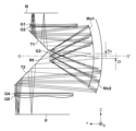
図2は、実施例1における投影光学系3の光線図である。マスクMの面上の図示された点、Ymax,Ymin,Qr,Ql(後述する図4参照)から発した光束は、マスク面直下の屈折光学部材G1,G2を通過後、第1平面反射鏡T1の作用で光路を直角に曲げられ、第1凹面鏡Mo1に入射する。第1凹面鏡Mo1で反射された光束は、投影光学系3の光軸O-O’近傍にある屈折光学部材G3を通過後、凸面鏡Mtに入射する。凸面鏡Mtは、この結像光学系の瞳である。凸面鏡Mtで反射した光束は、再び、屈折光学部材G3を通過後、第2凹面鏡Mo2に入射する。第2凹面鏡Mo2で反射した光束は、第2平面反射鏡T2に進行し、この作用で光路を直角に曲げられ、プレート面直上の屈折光学部材G4,G5を通過し、プレートPの面上に結像する。図2において、マスク面上の点Qr,Qlから発した光束のうち、第1凹面鏡Mo1や第2凹面鏡Mo2上で光軸O-O’に最も近い点と光軸O-O’との距離Du,Dlが示されている。これに関する説明は図5で後述する。本実施例の結像倍率は、1.15倍であり、開口数(NA)は0.105、露光幅は750mmである。いずれも、マスク面での値である。また、露光波長としては、i、h、g線を用い、これらに対して収差補正を行っている。これらを実現するための各光学部材の曲率半径R、間隔D、硝子部材の光学屈折率N、および対応する光学部材の参照符号が、表1にまとめられている。なお、光学部材のいくつかは、非球面で構成されていて、非球面形状を定義する式は、以下の式1で与えられる。各係数も表1に併記されている。
(Example 1)
FIG. 2 is a ray diagram of the projection
z=rh2/(1+(1-(1+k)r2h2)1/2)
+Ah4+Bh6+Ch8+Dh10+Eh12+Fh14+Gh16+Hh18+Jh20 …(式1)
ここで、rは表1における1/Rである。
z=rh 2 /(1+(1-(1+k)r 2 h 2 ) 1/2 )
+Ah 4 +Bh 6 +Ch 8 +Dh 10 +Eh 12 +Fh 14 +Gh 16 +Hh 18 +Jh 20 … (Formula 1)
Here, r is 1/R in Table 1.

図3は、本実施例の良像円弧領域内5点における横収差図であり、収差が適正に補正されていることを示している。ここで、図4および図5を用いて、本発明の原理について説明する。図4は、マスクM面上の円弧状露光領域を示す図である。スリット106は、投影光学系3の持つ軸外の輪帯状良像域のみを選択的に照明する。図4がその領域である。図4において、横軸はX方向、縦軸はY方向を示す。スリット106は、X方向に露光幅W、Y方向にスリット幅Swの照明領域を形成している。図4において、走査方向はY方向であり、この方向に、マスクMとプレートPが同期走査されて、プレートP全面が露光される。本明細書において、「露光幅」とは、マスク面上またはプレート面上での走査方向(Y方向)と直交する方向(X方向)の幅をいう。また、「スリット幅」とは、露光幅の中央におけるスリットの走査方向(Y方向)の幅をいう。ただし、以下に説明するように、図4の例では、露光幅のいずれの位置においてもスリットの走査方向(Y方向)の幅はSwで同一である。
FIG. 3 is a lateral aberration diagram at five points within the good-image arc region of this example, and shows that the aberrations are appropriately corrected. Here, the principle of the present invention will be explained using FIGS. 4 and 5. FIG. 4 is a diagram showing an arcuate exposure area on the mask M surface. The
図4において、Rは、この輪帯状露光領域を形成する円弧の最外半径であり、円弧の中心は光軸oに一致する構成をとる。この円弧をY方向(走査方向)にSwだけずらした位置に最内円弧が存在する。このような照明領域を設けることによって、マスクMとプレートPが走査露光される際に、露光幅全域(X方向)にわたり均一な積算露光量を得ることが可能となる。なお、均一な積算露光量を得るためには、図4と異なり、円弧の最内半径の中心を光軸oに一致させて、最内半径をY方向にSwだけずらした位置に最外円弧を形成することも可能である。図4において、Ymaxは、Y軸上における円弧の最高点を示し、Yminは、最低点を示している。また、点Qr,Qlは、円弧領域内で、Y軸からX方向に最も離れた左右の円弧最内点を示している。 In FIG. 4, R is the outermost radius of the circular arc forming this annular exposure area, and the center of the circular arc coincides with the optical axis o. The innermost arc exists at a position shifted by Sw from this arc in the Y direction (scanning direction). By providing such an illumination area, when the mask M and plate P are scanned and exposed, it becomes possible to obtain a uniform cumulative exposure amount over the entire exposure width (X direction). Note that in order to obtain a uniform cumulative exposure amount, unlike in FIG. It is also possible to form In FIG. 4, Ymax indicates the highest point of the arc on the Y axis, and Ymin indicates the lowest point. Further, points Qr and Ql indicate the innermost points of the left and right arcs that are farthest from the Y-axis in the X direction within the arc region.
図5は、凹面鏡上の有効光束領域(二点鎖線の内部)を示す模式図である。この図は、厳密には、光軸O-O’に垂直な面に光束を投影した図である。図5において、横軸はX方向、縦軸はZ方向を示す。図2において、第1平面反射鏡T1で折り曲げられた光束は、第1凹面鏡Mo1に入射する。本実施例の場合、マスク面と基板面において主光線がテレセントリックになるように設計されている。そのため、マスクM面上の各点(Ymax,Ymin,Qr,Ql)から発した結像光束の各主光線は、光軸O-O’に略平行に進行して第1凹面鏡Mo1に入射する。したがって、第1凹面鏡Mo1上では、図5の円弧領域がそのまま投影され、かつ、結像光束の広がった分が加算されて、光束の有効領域が決定される。図5において、一点鎖線の円弧領域が、図4で示されるマスク面上の円弧領域に等しく、rは各点で広がった光束の半径を示している。具体的には、rはマスク面から第1凹面鏡Mo1に至る光学距離と結像光束の開口数(NA)との積である。図5において、円弧のそり量Anは次式で定義される。 FIG. 5 is a schematic diagram showing the effective luminous flux area (inside the two-dot chain line) on the concave mirror. Strictly speaking, this figure is a diagram in which the light beam is projected onto a plane perpendicular to the optical axis O-O'. In FIG. 5, the horizontal axis indicates the X direction and the vertical axis indicates the Z direction. In FIG. 2, the light beam bent by the first plane reflecting mirror T1 enters the first concave mirror Mo1. In the case of this embodiment, the principal ray is designed to be telecentric on the mask surface and the substrate surface. Therefore, each principal ray of the imaging light beam emitted from each point (Ymax, Ymin, Qr, Ql) on the mask M surface travels approximately parallel to the optical axis OO' and enters the first concave mirror Mo1. . Therefore, on the first concave mirror Mo1, the arc region shown in FIG. 5 is projected as is, and the expanded portion of the imaging light beam is added to determine the effective region of the light beam. In FIG. 5, the arc region indicated by the dashed dotted line is equal to the arc region on the mask surface shown in FIG. 4, and r indicates the radius of the light beam spread at each point. Specifically, r is the product of the optical distance from the mask surface to the first concave mirror Mo1 and the numerical aperture (NA) of the imaging light beam. In FIG. 5, the amount of warpage An of the circular arc is defined by the following equation.
An = R- √(R**2-(W/2)**2)
したがって、第1凹面鏡Mo1上での有効光束領域は、図5において二点鎖線で示されているが、そのZ方向への広がり幅は、これまで定義した数値を用いて、Sw+2r+Anで表される。また、X方向への広がり幅は、W+2rである。ここで、本発明は、上記有効光束領域内で、X軸に最も近い点Pr,Plに着目し、これらとX軸との距離Dを規定する。点Pr,Plは、図4に示されるマスク面上Qr,Qlから発した光束のうち、最も光軸に近い点である。具体的には、照明領域の全ての物点からの光束によって第1凹面鏡Mo1または第2凹面鏡Mo2に形成される有効領域と、投影光学系3の光軸Oと直交しプレートPと平行な方向(X方向)に延びる直線との最小接近距離をDとする。
An = R- √(R**2-(W/2)**2)
Therefore, the effective luminous flux area on the first concave mirror Mo1 is shown by the two-dot chain line in FIG. 5, and its spread width in the Z direction is expressed as Sw+2r+An using the numerical values defined so far. . Further, the spread width in the X direction is W+2r. Here, the present invention focuses on the points Pr and Pl closest to the X-axis within the above-mentioned effective luminous flux area, and defines the distance D between these points and the X-axis. Points Pr and Pl are the points closest to the optical axis among the light beams emitted from Qr and Ql on the mask surface shown in FIG. Specifically, the effective area formed on the first concave mirror Mo1 or the second concave mirror Mo2 by the light beams from all object points in the illumination area, and the direction perpendicular to the optical axis O of the projection
すでに述べてきたように、凹面鏡を小径化するためには、この最小接近距離Dの値をできるだけ小さくすることが必要となる。このことは、求められる露光幅とスリット幅を確保しながら、円弧半径Rを小径化することに繋がる。そして、メカ的にも光学的にも効果がもたらされる。そのために、D値の上限値を以下に規定する。 As already mentioned, in order to reduce the diameter of the concave mirror, it is necessary to make the value of this minimum approach distance D as small as possible. This leads to reducing the arc radius R while ensuring the required exposure width and slit width. Then, effects are brought about both mechanically and optically. For this purpose, the upper limit of the D value is defined below.
我々の設計経験からすると、プレートP上に形成される円弧の最外周半径をRuとするとき、0<D≦0.1・Ruの条件を満たす場合には、凹面鏡の小径化や収差の低減化に寄与することが判っている。その理由の一つは、凹面鏡の外径は概して、円弧半径Ruの2倍(直径)に比例して大きくなり、(実際には、光束の広がり分が加算されるが)、その体積は、Ruの3乗で大きくなる。したがって、半径Ruが10%大きくなると、体積は約33%も肥大化してしまう。そのため、重量増加に伴いメカ的支持の難度が上がり、面変形が起き易くなるとともに、振動の固有振動数が1/√1.33倍に低下するため、露光中に床からの低周波振動を拾いやすくなってしまうからである。 From our design experience, when the outermost radius of the arc formed on the plate P is Ru, if the condition of 0<D ≦ 0.1・Ru is satisfied, it is possible to reduce the diameter of the concave mirror and reduce aberrations. It is known that it contributes to One of the reasons for this is that the outer diameter of a concave mirror generally increases in proportion to twice the arc radius (diameter) (although in reality, the spread of the luminous flux is added), and its volume is It increases as the cube of Ru. Therefore, if the radius Ru increases by 10%, the volume increases by about 33%. Therefore, as the weight increases, the difficulty of mechanical support increases, surface deformation becomes more likely to occur, and the natural frequency of vibration decreases to 1/√1.33 times, so low frequency vibrations from the floor are suppressed during exposure. This is because it becomes easier to pick up.
また、収差補正の観点からも、物像高が10%高くなると、特に、ディストーションや像面湾曲、非点収差といった像高に依存する収差は急激に悪化することが判っている。同様な理由から、プレート上に形成される円弧の最内周半径をRlとするとき、0<D<0.1・Rlの条件を満たす場合には、凹面鏡の小径化や収差の低減化に寄与することが判っている。 Furthermore, from the viewpoint of aberration correction, it has been found that when the object image height increases by 10%, aberrations that depend on the image height, such as distortion, field curvature, and astigmatism, deteriorate rapidly. For the same reason, when the innermost radius of the arc formed on the plate is Rl, if the condition of 0<D<0.1・Rl is satisfied, it is possible to reduce the diameter of the concave mirror and reduce aberrations. It is known to contribute.
また、プレート上に形成される円弧の最外周半径と最内周半径のZ軸上の位置における差をSwとするとき、0<D<1.15・Swの条件を満たす場合には、凹面鏡の小径化や収差の低減化に寄与することが判っている。この理由は以下のように説明される。通常、スリット幅はできるだけ広く設計しようとする。それは、積算露光量を増やし、露光時間を短縮するためである。ところが、設計上はスリット内の像高間でも収差が悪化してしまう。具体的には、スリットの最大像高と最小像高間で像面湾曲等の収差が変化し、それが収差許容値ぎりぎりとなることが多い。換言すれば、スリット幅は、像高拡大に伴う収差劣化の一つの基準となることを意味する。よって、スリット幅Sw以内にD値の増加を抑えることが収差の悪化を抑えるために必要とみなされる。
In addition, when the difference in position on the Z-axis between the outermost radius and the innermost radius of the arc formed on the plate is Sw, if the
図6は、実施例1の投影光学系3における凹面鏡上の有効光束領域を示すトレース図である。マスク面M上の円弧領域内で、X方向に7点、Y方向に3点、計21点から発した結像光束が、第1凹面鏡Mo1上で円の集合を形成しているのが判る。これら全体を含む領域が、図5で示した二点鎖線の内部に対応している。光軸Oより上半円内の円群は、マスク面から発し、第1凹面鏡Mo1に形成される光束群であり、図5で示した最短距離DはDuで表されている。また、光軸Oより下半円内の円群は、第2凹面鏡Mo2に形成される光束群であり、図5で示した最短距離DはDlで表される。
FIG. 6 is a trace diagram showing the effective light flux area on the concave mirror in the projection
本実施例における光学系の諸元値を図13にまとめて示す。なお、図13において、各諸元(NA、スリット幅、露光幅、Ymax、テレセン度)の接尾辞として記載されているmは、夫々の諸元が、マスク面側でとる値であることを示している。また、凹面径φ/2 m、Dm、そして、凹面テレセン度 mは、図5を第1凹面鏡に適用した場合の凹面鏡半径、最短距離D、そして、スリット中央物点から発した光束の主光線が第1凹面鏡に入射する際のテレセン度を夫々示している。同様に、各諸元の接尾辞として記載されているpは、上記各諸元が、プレート面側または第2凹面鏡上でとる値を示している。 The specification values of the optical system in this example are summarized in FIG. 13. In addition, in FIG. 13, m written as a suffix of each specification (NA, slit width, exposure width, Ymax, degree of telecentricity) indicates that each specification is a value taken on the mask surface side. It shows. In addition, the concave diameter φ/2 m, Dm, and the concave telecentricity m are the concave mirror radius when Fig. 5 is applied to the first concave mirror, the shortest distance D, and the principal ray of the light beam emitted from the slit central object point. respectively indicate the degree of telecentricity when the light is incident on the first concave mirror. Similarly, p written as a suffix of each specification indicates the value that each of the above specifications takes on the plate surface side or the second concave mirror.
図13の例によれば、照明領域の基板面上での走査方向と直交する方向(X方向)の幅Wを表す「露光幅 p」は、863mmとされている。実施形態において、この幅Wについては、W≧780mmの条件を満たすとよい。 According to the example of FIG. 13, the "exposure width p" representing the width W of the illumination area on the substrate surface in the direction (X direction) orthogonal to the scanning direction is 863 mm. In the embodiment, the width W preferably satisfies the condition W≧780 mm.
(実施例2)
図7は、実施例2における投影光学系3の光線図である。本実施例の投影光学系3は拡大系である。例えばその結像倍率は、1.25倍であり、開口数(NA)は0.1、露光幅は750mmである。いずれも、マスク面Mでの値である。また、露光波長としては、i、h、g線を用い、これらに対して収差補正を行っている。マスク面Mからプレート面Pへ光線が進行する過程や途中の光学部材の基本的構成は図2と同じであるので、説明は割愛する。各光学部材の曲率半径R、間隔D、硝子部材の光学屈折率N、および対応する光学部材の参照符号が、表2にまとめられている。
(Example 2)
FIG. 7 is a ray diagram of the projection

非球面形状を定義する式は、前記した式1と同じである。また、最短距離Dについての上限規定も実施例1と同じである。
The equation defining the aspherical shape is the same as
本実施例における光学系の諸元値を図13にまとめて示す。 The specification values of the optical system in this example are summarized in FIG. 13.
図8は、本実施例の良像円弧領域内5点における横収差図であり、収差が適正に補正されていることを示している。 FIG. 8 is a lateral aberration diagram at five points within the good-image arc region of this example, and shows that the aberrations are appropriately corrected.
(実施例3)
図9は、実施例3における投影光学系3の光線図である。本実施例の投影光学系3は拡大系である。例えばその結像倍率は、1.49倍であり、開口数(NA)は0.105、露光幅は750mmである。いずれも、マスク面Mでの値である。また、露光波長としては、i、h、g線を用い、これらに対して収差補正を行っている。マスク面Mからプレート面Pへ光線が進行する過程や途中の光学部材の基本的構成は図2と同じである。各光学部材の曲率半径R、間隔D、硝子部材の光学屈折率N、および対応する光学部材の参照符号が、表3にまとめられている。
(Example 3)
FIG. 9 is a ray diagram of the projection

非球面形状を定義する式は、前記した式1と同じである。
The equation defining the aspherical shape is the same as
図10は、本実施例の良像円弧領域内5点における横収差図であり、収差が適正に補正されていることを示している。 FIG. 10 is a lateral aberration diagram at five points within the good image arc region of this example, and shows that the aberrations are appropriately corrected.
本実施例においては、第1凹面鏡Mo1と第2凹面鏡Moとが略同位置に重なって配置されている。そして、これまで述べた2つの実施例と最も異なる点は、第1凹面鏡Mo1に入射する主光線の角度(第1角度)が光軸O-O’に近づく方向に傾いている(図9の矢印A1)点である。また、同様に、第2凹面鏡Mo2から射出する主光線の角度(第2角度)が光軸O-O’から離れる方向に傾いている(図9の矢印A2)点にある。以降、このような主光線の状態を「内側テレセン」と称する。以下、この効果について説明する。 In this embodiment, the first concave mirror Mo1 and the second concave mirror Mo are arranged to overlap each other at substantially the same position. The most different point from the two embodiments described so far is that the angle (first angle) of the chief ray incident on the first concave mirror Mo1 is inclined in the direction approaching the optical axis OO' (see FIG. 9). This is the point indicated by the arrow A1). Similarly, the angle (second angle) of the principal ray emerging from the second concave mirror Mo2 is at a point (arrow A2 in FIG. 9) inclined in a direction away from the optical axis O-O'. Hereinafter, such a state of the chief ray will be referred to as an "inner telecenter." This effect will be explained below.
図11は、凹面鏡上の有効光束領域を示す模式図である。図5で説明した内容と概ね同じであるが、図5と異なる点は、本実施例では主光線が2つの凹面鏡に対して内側テレセンで入射あるいは射出するために、凹面鏡上での有効光束は、更に、光軸Oに近づいて投影される。このことは、マスク面またはプレート面の近傍にあるレンズ群(図9におけるG1,G2,G4,G5)が、光学的に正の屈折力を有することにより実現される。表3に示されるように、レンズ群は、非球面形状を有するレンズを含みうる。この作用の結果、マスク面上の1点から発した光束は、凹面鏡に進行する際、内側テレセンになるだけでなく、光束径自体も収斂作用を受けるため、凹面鏡上では、図5より小径化され、投影される。図11において、r’がその半径である。また、円弧スリットの幅や円弧の反りも、同様な収斂作用を受けて、縮小される(図11中、Sw’、An’)。 FIG. 11 is a schematic diagram showing an effective light flux area on a concave mirror. The content is almost the same as that explained in FIG. 5, but the difference from FIG. 5 is that in this example, the principal ray enters or exits the two concave mirrors at an inner telecenter, so the effective luminous flux on the concave mirrors is , is projected further closer to the optical axis O. This is achieved by the lens group (G1, G2, G4, G5 in FIG. 9) located near the mask surface or plate surface having optically positive refractive power. As shown in Table 3, the lens group may include lenses having an aspherical shape. As a result of this effect, when the light beam emitted from one point on the mask surface travels to the concave mirror, it not only becomes an inner telecenter, but also the diameter of the light beam itself is converged, so the diameter becomes smaller on the concave mirror than in Figure 5. and projected. In FIG. 11, r' is its radius. Further, the width of the arc slit and the warp of the arc are also reduced by the same convergence effect (Sw', An' in FIG. 11).
以上の説明により、図11に示されるように、凹面鏡上での有効光束領域は、二点鎖線の領域(図5における有効光束領域)から、破線の領域に移動され(円弧最高点AがA’へ、円弧最低点BがB’へ移動)、かつ、縮小されることになる。その結果、本発明の目的である凹面鏡の小径化に寄与することができる。 With the above explanation, as shown in FIG. 11, the effective luminous flux area on the concave mirror is moved from the area indicated by the two-dot chain line (the effective luminous flux area in FIG. 5) to the area indicated by the broken line (the highest point A of the arc is ', the lowest point B of the arc moves to B') and is reduced. As a result, it is possible to contribute to reducing the diameter of a concave mirror, which is the objective of the present invention.
図12は、本実施例の光学系における凹面鏡上の有効光束領域を示すトレース図である。マスクM面上の円弧領域内で、X方向に7点、Y方向に3点、計21点から発した結像光束が、第1凹面鏡上で円の集合を形成しているのが判る。これら全体を含む領域が、図11で示した破線の内部に対応している。光軸Oより上半円内の円群は、マスク面から発し、第1凹面鏡Mo1に形成される光束群であり、図11で示した最短距離D’はDuで表されている。また、光軸Oより下半円内の円群は、第2凹面鏡Mo2に形成される光束群であり、図11で示した最短距離D’はDlで表される。 FIG. 12 is a trace diagram showing the effective light flux area on the concave mirror in the optical system of this example. It can be seen that the imaging light beams emitted from a total of 21 points, 7 points in the X direction and 3 points in the Y direction, form a set of circles on the first concave mirror within the arc region on the mask M surface. The area including all of these corresponds to the inside of the broken line shown in FIG. The group of circles in the upper semicircle from the optical axis O is a group of light beams emitted from the mask surface and formed on the first concave mirror Mo1, and the shortest distance D' shown in FIG. 11 is represented by Du. Further, a group of circles in a semicircle below the optical axis O is a group of light fluxes formed on the second concave mirror Mo2, and the shortest distance D' shown in FIG. 11 is represented by Dl.
本実施例における投影光学系3の諸元値を図13にまとめて示す。図13において、第1凹面鏡Mo1に入射する主光線の角度である第1角度を表す第1テレセン度は、「凹面テレセン度 m」として示されている。また、第2凹面鏡Mo2から射出する主光線の角度である第2角度を表す第2テレセン度は、「凹面テレセン度 p」として示されている。本実施例においては、例えば、第1テレセン度の絶対値または第2テレセン度の絶対値が、0.015ラジアン以上である。図13において、実施例3における「凹面テレセン度 m」は-0.062ラジアン、「凹面テレセン度 p」は-0.1569ラジアンであり、第1テレセン度の絶対値および第2テレセン度の絶対値が共に、0.015ラジアン以上であることが示されている。また、図13において、マスク面におけるテレセン度は「テレセン度 m」として示され、プレート面におけるテレセン度は「テレセン度 p」として示されている。図13では両者は、0.05ラジアン以下であることが示されている。これらは、±0.05ラジアン以内であることが好ましい。
The specification values of the projection
なお、以上の実施例においては、拡大系を主に述べて来たが、本発明の範囲としては、縮小系も含む。このことは、光学系を反転させれば容易に理解できる。また、本発明が適用される範囲は、図13に示した設計値に限定されるものではない。元来、ミラー系であり色収差が小さいので、使用波長がi線より短い遠紫外線領域(DUV)にも適用できるし、開口数(NA)、スリット幅、そして、凹面鏡の口径等にも特に制限を加える必要もない。 In the above embodiments, the enlargement system has been mainly described, but the scope of the present invention also includes the reduction system. This can be easily understood by inverting the optical system. Further, the range to which the present invention is applied is not limited to the design values shown in FIG. 13. Since it is originally a mirror system and has small chromatic aberration, it can be applied to the deep ultraviolet region (DUV), where the wavelength used is shorter than the i-line, and there are particular restrictions on numerical aperture (NA), slit width, and concave mirror aperture. There is no need to add.
以上説明した実施形態に従う投影光学系によれば、露光用円弧状スリットの半径を小径化できるため、光学設計上、低い物像高で、より高精度な収差補正が可能となる。小径で軽量の凹面鏡を用いて、広い露光幅を広い露光スリットで一括露光できる。凹面鏡の小型化によって、メカ支持による面変形が低減されると共に、露光時の振動の影響を抑えることができる。その結果、露光中でも高解像力が維持され、高精細なパネルを高生産性で露光することが可能となる。 According to the projection optical system according to the embodiments described above, the radius of the arcuate slit for exposure can be reduced, so that more accurate aberration correction is possible with a low object image height in terms of optical design. Using a small diameter and lightweight concave mirror, a wide exposure width can be exposed all at once with a wide exposure slit. By downsizing the concave mirror, surface deformation due to mechanical support can be reduced, and the influence of vibrations during exposure can be suppressed. As a result, high resolution is maintained even during exposure, making it possible to expose a high-definition panel with high productivity.
また、これまで、主に、拡大光学系において凹面鏡が別体となる点に関して述べてきたが、本発明はこれに限定されるものではない。すなわち、等倍系の場合、光学設計的には第1凹面鏡と第2凹面鏡が同一のものになるが、装置構成上、これを割って、別体支持とする場合も、本発明の適用範囲である。 Further, so far, the description has mainly been made regarding the point that the concave mirror is a separate body in the magnifying optical system, but the present invention is not limited to this. In other words, in the case of a 1-magnification system, the first concave mirror and the second concave mirror are the same in terms of optical design, but the scope of the present invention also applies if they are split and supported separately due to the device configuration. It is.
<物品製造方法の実施形態>
本発明の実施形態に係る物品製造方法は、例えば、半導体デバイス等のマイクロデバイスや微細構造を有する素子等の物品を製造するのに好適である。本実施形態の物品製造方法は、基板に塗布された感光剤に上記の露光装置を用いて潜像パターンを形成する工程(基板を露光する工程)と、かかる工程で潜像パターンが形成された基板を現像する工程とを含む。更に、かかる製造方法は、他の周知の工程(酸化、成膜、蒸着、ドーピング、平坦化、エッチング、レジスト剥離、ダイシング、ボンディング、パッケージング等)を含む。本実施形態の物品製造方法は、従来の方法に比べて、物品の性能・品質・生産性・生産コストの少なくとも1つにおいて有利である。
<Embodiment of article manufacturing method>
The article manufacturing method according to the embodiment of the present invention is suitable for manufacturing articles such as micro devices such as semiconductor devices and elements having fine structures. The article manufacturing method of the present embodiment includes a step of forming a latent image pattern on a photosensitive agent applied to a substrate using the above exposure device (a step of exposing the substrate), and a step of forming a latent image pattern in this step. and developing the substrate. Additionally, such manufacturing methods include other well-known steps (oxidation, deposition, deposition, doping, planarization, etching, resist stripping, dicing, bonding, packaging, etc.). The article manufacturing method of this embodiment is advantageous in at least one of article performance, quality, productivity, and production cost compared to conventional methods.
発明は上記実施形態に制限されるものではなく、発明の精神及び範囲から離脱することなく、様々な変更及び変形が可能である。従って、発明の範囲を公にするために請求項を添付する。 The invention is not limited to the embodiments described above, and various changes and modifications can be made without departing from the spirit and scope of the invention. Therefore, the following claims are hereby appended to disclose the scope of the invention.
M:マスク、G1~G5:屈折光学部材、T1:第1平面反射鏡、T2:第2平面反射鏡、Mt:凸面鏡、P:プレート(基板) M: mask, G1 to G5: refractive optical member, T1: first plane reflecting mirror, T2: second plane reflecting mirror, Mt: convex mirror, P: plate (substrate)
Claims (11)
前記マスクのパターンを前記基板に投影する投影光学系を有し、
前記投影光学系は、第1凹面鏡、凸面鏡、および第2凹面鏡を含み、前記マスクのパターンを透過した光が前記第1凹面鏡、前記凸面鏡、および前記第2凹面鏡の順に反射するように構成され、
前記マスク上における円弧状の照明領域の全ての物点からの光束によって前記第1凹面鏡に形成される有効領域と、前記投影光学系の光軸と直交し前記基板と平行な方向に延びる直線との最小距離をDuとし、前記第2凹面鏡に形成される有効領域と、前記直線との最小距離をDlとし、前記基板上に形成される前記円弧の最外周半径をRuとするとき、
0<Du≦0.1・Ru
又は
0<Dl≦0.1・Ru
の少なくとも一方の条件を満たすことを特徴とする露光装置。 An exposure apparatus that exposes a substrate while scanning a mask and a substrate,
a projection optical system that projects the pattern of the mask onto the substrate;
The projection optical system includes a first concave mirror, a convex mirror, and a second concave mirror, and is configured such that light transmitted through the pattern of the mask is reflected in the order of the first concave mirror, the convex mirror, and the second concave mirror,
an effective area formed on the first concave mirror by light beams from all object points in an arc-shaped illumination area on the mask; and a straight line extending in a direction perpendicular to the optical axis of the projection optical system and parallel to the substrate. When the minimum distance of is Du , the minimum distance between the effective area formed on the second concave mirror and the straight line is Dl, and the outermost radius of the arc formed on the substrate is Ru,
0<D u≦ 0.1・Ru
or
0<Dl≦0.1・Ru
An exposure apparatus characterized by satisfying at least one of the following conditions.
前記マスクのパターンを前記基板に投影する投影光学系を有し、
前記投影光学系は、第1凹面鏡、凸面鏡、および第2凹面鏡を含み、前記マスクのパターンを透過した光が前記第1凹面鏡、前記凸面鏡、および前記第2凹面鏡の順に入射し、
前記マスク上における円弧状の照明領域の全ての物点からの光束によって前記第1凹面鏡に形成される有効領域と、前記投影光学系の光軸と直交し前記基板と平行な方向に延びる直線との最小距離をDuとし、前記第2凹面鏡に形成される有効領域と、前記直線との最小距離をDlとし、前記基板上に形成される前記円弧の最外周半径と最内周半径との間の、前記直線に沿う方向の中央における差をSwとするとき、
0<Du<1.15・Sw
又は
0<Dl<1.15・Sw
の少なくとも一方の条件を満たすことを特徴とする露光装置。 An exposure apparatus that exposes a substrate while scanning a mask and a substrate,
a projection optical system that projects the pattern of the mask onto the substrate;
The projection optical system includes a first concave mirror, a convex mirror, and a second concave mirror, and the light transmitted through the pattern of the mask enters the first concave mirror, the convex mirror, and the second concave mirror in this order,
an effective area formed on the first concave mirror by light beams from all object points in an arc-shaped illumination area on the mask; and a straight line extending in a direction perpendicular to the optical axis of the projection optical system and parallel to the substrate. Let Du be the minimum distance between the effective area formed on the second concave mirror and the straight line, and let Dl be the minimum distance between the effective area formed on the second concave mirror and the straight line, and the outermost radius and the innermost radius of the arc formed on the substrate. When the difference at the center in the direction along the straight line between is Sw,
0<D u <1.15・Sw
or
0<Dl<1.15・Sw
An exposure apparatus characterized by satisfying at least one of the following conditions.
前記投影光学系は、前記マスク面または前記基板面の近傍に正の屈折力を持つレンズ群を更に含み、
前記第1凹面鏡に入射する主光線の角度である第1角度が前記投影光学系の光軸に近づく方向に傾いている、または、前記第2凹面鏡から射出する主光線の角度である第2角度が前記光軸から離れる方向に傾いている、
ことを特徴とする請求項1又は2に記載の露光装置。 The projection optical system is telecentric on the mask surface and the substrate surface,
The projection optical system further includes a lens group having a positive refractive power near the mask surface or the substrate surface,
A first angle, which is the angle of the principal ray incident on the first concave mirror, is inclined in a direction approaching the optical axis of the projection optical system, or a second angle, which is the angle of the principal ray exiting from the second concave mirror. is tilted away from the optical axis,
The exposure apparatus according to claim 1 or 2, characterized in that:
W≧780mm
の条件を満たすことを特徴とする請求項1乃至6のいずれか1項に記載の露光装置。 When the width of the illumination area on the substrate surface in a direction perpendicular to the scanning direction is W,
W≧780mm
7. The exposure apparatus according to claim 1, wherein the exposure apparatus satisfies the following conditions.
前記露光された基板を現像する工程と、
を含み、前記現像された基板から物品を製造することを特徴とする物品製造方法。 A step of exposing a substrate using the exposure apparatus according to any one of claims 1 to 10 ;
Developing the exposed substrate;
A method for manufacturing an article, comprising: manufacturing an article from the developed substrate.
Priority Applications (4)
| Application Number | Priority Date | Filing Date | Title |
|---|---|---|---|
| JP2019161464A JP7357488B2 (en) | 2019-09-04 | 2019-09-04 | Exposure device and article manufacturing method |
| TW109126462A TWI825339B (en) | 2019-09-04 | 2020-08-05 | Exposure device, and method of manufacturing the article |
| KR1020200107614A KR20210028574A (en) | 2019-09-04 | 2020-08-26 | Exposure apparatus and method of manufacturing article |
| CN202010922291.5A CN112445082B (en) | 2019-09-04 | 2020-09-04 | Exposure apparatus and article manufacturing method |
Applications Claiming Priority (1)
| Application Number | Priority Date | Filing Date | Title |
|---|---|---|---|
| JP2019161464A JP7357488B2 (en) | 2019-09-04 | 2019-09-04 | Exposure device and article manufacturing method |
Publications (3)
| Publication Number | Publication Date |
|---|---|
| JP2021039282A JP2021039282A (en) | 2021-03-11 |
| JP2021039282A5 JP2021039282A5 (en) | 2022-08-24 |
| JP7357488B2 true JP7357488B2 (en) | 2023-10-06 |
Family
ID=74735493
Family Applications (1)
| Application Number | Title | Priority Date | Filing Date |
|---|---|---|---|
| JP2019161464A Active JP7357488B2 (en) | 2019-09-04 | 2019-09-04 | Exposure device and article manufacturing method |
Country Status (4)
| Country | Link |
|---|---|
| JP (1) | JP7357488B2 (en) |
| KR (1) | KR20210028574A (en) |
| CN (1) | CN112445082B (en) |
| TW (1) | TWI825339B (en) |
Families Citing this family (1)
| Publication number | Priority date | Publication date | Assignee | Title |
|---|---|---|---|---|
| CN113296342B (en) * | 2021-05-21 | 2024-03-12 | 光感(上海)科技有限公司 | Optical projection system |
Citations (3)
| Publication number | Priority date | Publication date | Assignee | Title |
|---|---|---|---|---|
| JP2001507873A (en) | 1997-11-07 | 2001-06-12 | コーニンクレッカ フィリップス エレクトロニクス エヌ ヴィ | Three-mirror optical system for lithographic projection and a projection apparatus having the mirror optical system |
| JP2005025199A (en) | 2003-06-30 | 2005-01-27 | Asml Holding Nv | Exposure system for manufacture of flat panel display, and unit magnification annular optical system for manufacture of flat panel display |
| JP2008286888A5 (en) | 2007-05-15 | 2010-07-15 |
Family Cites Families (10)
| Publication number | Priority date | Publication date | Assignee | Title |
|---|---|---|---|---|
| JP2008089832A (en) | 2006-09-29 | 2008-04-17 | Canon Inc | Lithography device |
| JP5196869B2 (en) | 2007-05-15 | 2013-05-15 | キヤノン株式会社 | Projection optical system, exposure apparatus, and device manufacturing method |
| KR101010605B1 (en) | 2007-10-15 | 2011-01-24 | 재단법인 포항산업과학연구원 | Automatic heat treatment apparatus for u-type bending pipe |
| JP5398185B2 (en) * | 2008-07-09 | 2014-01-29 | キヤノン株式会社 | Projection optical system, exposure apparatus, and device manufacturing method |
| JP2010135479A (en) * | 2008-12-03 | 2010-06-17 | Canon Inc | Scanning projection exposure apparatus |
| JP5595001B2 (en) * | 2009-10-06 | 2014-09-24 | キヤノン株式会社 | Projection optical system, exposure apparatus, and device manufacturing method |
| DE102014218474A1 (en) * | 2014-09-15 | 2016-03-17 | Carl Zeiss Smt Gmbh | Projection objective, projection exposure apparatus and projection exposure method for EUV microlithography |
| US10025079B2 (en) * | 2015-09-28 | 2018-07-17 | Kenneth Carlisle Johnson | Actinic, spot-scanning microscope for EUV mask inspection and metrology |
| JP6661371B2 (en) * | 2015-12-25 | 2020-03-11 | キヤノン株式会社 | Evaluation method, exposure method, and article manufacturing method |
| JP6748482B2 (en) * | 2016-05-25 | 2020-09-02 | キヤノン株式会社 | Exposure apparatus and method for manufacturing article |
-
2019
- 2019-09-04 JP JP2019161464A patent/JP7357488B2/en active Active
-
2020
- 2020-08-05 TW TW109126462A patent/TWI825339B/en active
- 2020-08-26 KR KR1020200107614A patent/KR20210028574A/en not_active Application Discontinuation
- 2020-09-04 CN CN202010922291.5A patent/CN112445082B/en active Active
Patent Citations (3)
| Publication number | Priority date | Publication date | Assignee | Title |
|---|---|---|---|---|
| JP2001507873A (en) | 1997-11-07 | 2001-06-12 | コーニンクレッカ フィリップス エレクトロニクス エヌ ヴィ | Three-mirror optical system for lithographic projection and a projection apparatus having the mirror optical system |
| JP2005025199A (en) | 2003-06-30 | 2005-01-27 | Asml Holding Nv | Exposure system for manufacture of flat panel display, and unit magnification annular optical system for manufacture of flat panel display |
| JP2008286888A5 (en) | 2007-05-15 | 2010-07-15 |
Also Published As
| Publication number | Publication date |
|---|---|
| CN112445082B (en) | 2024-03-19 |
| CN112445082A (en) | 2021-03-05 |
| JP2021039282A (en) | 2021-03-11 |
| KR20210028574A (en) | 2021-03-12 |
| TWI825339B (en) | 2023-12-11 |
| TW202111382A (en) | 2021-03-16 |
Similar Documents
| Publication | Publication Date | Title |
|---|---|---|
| KR102266723B1 (en) | Projection optical system, exposure apparatus, and article manufacturing method | |
| JP2004214242A (en) | Reflection-type projection optical system, aligner and device manufacturing method | |
| JP3925576B2 (en) | Projection optical system, exposure apparatus including the optical system, and device manufacturing method using the apparatus | |
| JP2004252358A (en) | Reflective projection optical system and exposing device | |
| US6947210B2 (en) | Catoptric projection optical system, exposure apparatus and device fabrication method using same | |
| JPH10275771A (en) | Lighting optical system | |
| KR20080091182A (en) | Cata-dioptric imaging system, exposure device, and device manufacturing method | |
| US6860610B2 (en) | Reflection type projection optical system, exposure apparatus and device fabrication method using the same | |
| JP2006147809A (en) | Aligner, projection optical system thereof, and method of manufacturing device | |
| KR101892766B1 (en) | Reflective imaging optical system, exposure apparatus, and method for producing device | |
| JP7357488B2 (en) | Exposure device and article manufacturing method | |
| JP2010107596A (en) | Reflection type projection optical system, exposure device, and method of manufacturing device | |
| JP2004158786A (en) | Projection optical system and exposure device | |
| JP2006138940A (en) | Cata-dioptric projection system, exposing device having cata-dioptric projection system, and method for producing device | |
| JP7332415B2 (en) | Projection optical system, scanning exposure apparatus and article manufacturing method | |
| US11966043B2 (en) | Imaging optical system, exposure apparatus, and article manufacturing method | |
| JP2022022911A (en) | Imaging optical system, exposure apparatus, and article manufacturing method | |
| JP2004271552A (en) | Enlarging and projecting optical system | |
| JP2021092684A (en) | Projection optical system, exposure device and method of manufacturing article | |
| JP2022030810A (en) | Projection optical system, exposure device, and method for manufacturing article | |
| JP2023010009A (en) | Projection optical system, exposure device, and method for manufacturing article | |
| JP2009162951A (en) | Catadioptric projection optical system and exposure device having the same | |
| JP2023004358A (en) | Projection optical system, exposure device, and article production method | |
| JP2019211798A (en) | Projection optical system, exposure apparatus, and manufacturing method of items | |
| JP2004342711A (en) | Optical illumination apparatus, aligner, and exposure method |
Legal Events
| Date | Code | Title | Description |
|---|---|---|---|
| RD01 | Notification of change of attorney |
Free format text: JAPANESE INTERMEDIATE CODE: A7421 Effective date: 20210103 |
|
| A521 | Request for written amendment filed |
Free format text: JAPANESE INTERMEDIATE CODE: A523 Effective date: 20210113 |
|
| A521 | Request for written amendment filed |
Free format text: JAPANESE INTERMEDIATE CODE: A523 Effective date: 20220816 |
|
| A621 | Written request for application examination |
Free format text: JAPANESE INTERMEDIATE CODE: A621 Effective date: 20220816 |
|
| A977 | Report on retrieval |
Free format text: JAPANESE INTERMEDIATE CODE: A971007 Effective date: 20230417 |
|
| A131 | Notification of reasons for refusal |
Free format text: JAPANESE INTERMEDIATE CODE: A131 Effective date: 20230425 |
|
| A521 | Request for written amendment filed |
Free format text: JAPANESE INTERMEDIATE CODE: A523 Effective date: 20230619 |
|
| TRDD | Decision of grant or rejection written | ||
| A01 | Written decision to grant a patent or to grant a registration (utility model) |
Free format text: JAPANESE INTERMEDIATE CODE: A01 Effective date: 20230828 |
|
| A61 | First payment of annual fees (during grant procedure) |
Free format text: JAPANESE INTERMEDIATE CODE: A61 Effective date: 20230926 |
|
| R151 | Written notification of patent or utility model registration |
Ref document number: 7357488 Country of ref document: JP Free format text: JAPANESE INTERMEDIATE CODE: R151 |