JP7357165B2 - display device - Google Patents
display device Download PDFInfo
- Publication number
- JP7357165B2 JP7357165B2 JP2022538541A JP2022538541A JP7357165B2 JP 7357165 B2 JP7357165 B2 JP 7357165B2 JP 2022538541 A JP2022538541 A JP 2022538541A JP 2022538541 A JP2022538541 A JP 2022538541A JP 7357165 B2 JP7357165 B2 JP 7357165B2
- Authority
- JP
- Japan
- Prior art keywords
- transistor
- control
- terminal connected
- conduction terminal
- terminal
- Prior art date
- Legal status (The legal status is an assumption and is not a legal conclusion. Google has not performed a legal analysis and makes no representation as to the accuracy of the status listed.)
- Active
Links
Images


Classifications
-
- G—PHYSICS
- G09—EDUCATION; CRYPTOGRAPHY; DISPLAY; ADVERTISING; SEALS
- G09G—ARRANGEMENTS OR CIRCUITS FOR CONTROL OF INDICATING DEVICES USING STATIC MEANS TO PRESENT VARIABLE INFORMATION
- G09G3/00—Control arrangements or circuits, of interest only in connection with visual indicators other than cathode-ray tubes
- G09G3/20—Control arrangements or circuits, of interest only in connection with visual indicators other than cathode-ray tubes for presentation of an assembly of a number of characters, e.g. a page, by composing the assembly by combination of individual elements arranged in a matrix no fixed position being assigned to or needed to be assigned to the individual characters or partial characters
- G09G3/22—Control arrangements or circuits, of interest only in connection with visual indicators other than cathode-ray tubes for presentation of an assembly of a number of characters, e.g. a page, by composing the assembly by combination of individual elements arranged in a matrix no fixed position being assigned to or needed to be assigned to the individual characters or partial characters using controlled light sources
- G09G3/30—Control arrangements or circuits, of interest only in connection with visual indicators other than cathode-ray tubes for presentation of an assembly of a number of characters, e.g. a page, by composing the assembly by combination of individual elements arranged in a matrix no fixed position being assigned to or needed to be assigned to the individual characters or partial characters using controlled light sources using electroluminescent panels
- G09G3/32—Control arrangements or circuits, of interest only in connection with visual indicators other than cathode-ray tubes for presentation of an assembly of a number of characters, e.g. a page, by composing the assembly by combination of individual elements arranged in a matrix no fixed position being assigned to or needed to be assigned to the individual characters or partial characters using controlled light sources using electroluminescent panels semiconductive, e.g. using light-emitting diodes [LED]
- G09G3/3208—Control arrangements or circuits, of interest only in connection with visual indicators other than cathode-ray tubes for presentation of an assembly of a number of characters, e.g. a page, by composing the assembly by combination of individual elements arranged in a matrix no fixed position being assigned to or needed to be assigned to the individual characters or partial characters using controlled light sources using electroluminescent panels semiconductive, e.g. using light-emitting diodes [LED] organic, e.g. using organic light-emitting diodes [OLED]
- G09G3/3225—Control arrangements or circuits, of interest only in connection with visual indicators other than cathode-ray tubes for presentation of an assembly of a number of characters, e.g. a page, by composing the assembly by combination of individual elements arranged in a matrix no fixed position being assigned to or needed to be assigned to the individual characters or partial characters using controlled light sources using electroluminescent panels semiconductive, e.g. using light-emitting diodes [LED] organic, e.g. using organic light-emitting diodes [OLED] using an active matrix
- G09G3/3233—Control arrangements or circuits, of interest only in connection with visual indicators other than cathode-ray tubes for presentation of an assembly of a number of characters, e.g. a page, by composing the assembly by combination of individual elements arranged in a matrix no fixed position being assigned to or needed to be assigned to the individual characters or partial characters using controlled light sources using electroluminescent panels semiconductive, e.g. using light-emitting diodes [LED] organic, e.g. using organic light-emitting diodes [OLED] using an active matrix with pixel circuitry controlling the current through the light-emitting element
-
- G—PHYSICS
- G09—EDUCATION; CRYPTOGRAPHY; DISPLAY; ADVERTISING; SEALS
- G09G—ARRANGEMENTS OR CIRCUITS FOR CONTROL OF INDICATING DEVICES USING STATIC MEANS TO PRESENT VARIABLE INFORMATION
- G09G3/00—Control arrangements or circuits, of interest only in connection with visual indicators other than cathode-ray tubes
- G09G3/20—Control arrangements or circuits, of interest only in connection with visual indicators other than cathode-ray tubes for presentation of an assembly of a number of characters, e.g. a page, by composing the assembly by combination of individual elements arranged in a matrix no fixed position being assigned to or needed to be assigned to the individual characters or partial characters
- G09G3/22—Control arrangements or circuits, of interest only in connection with visual indicators other than cathode-ray tubes for presentation of an assembly of a number of characters, e.g. a page, by composing the assembly by combination of individual elements arranged in a matrix no fixed position being assigned to or needed to be assigned to the individual characters or partial characters using controlled light sources
- G09G3/30—Control arrangements or circuits, of interest only in connection with visual indicators other than cathode-ray tubes for presentation of an assembly of a number of characters, e.g. a page, by composing the assembly by combination of individual elements arranged in a matrix no fixed position being assigned to or needed to be assigned to the individual characters or partial characters using controlled light sources using electroluminescent panels
- G09G3/32—Control arrangements or circuits, of interest only in connection with visual indicators other than cathode-ray tubes for presentation of an assembly of a number of characters, e.g. a page, by composing the assembly by combination of individual elements arranged in a matrix no fixed position being assigned to or needed to be assigned to the individual characters or partial characters using controlled light sources using electroluminescent panels semiconductive, e.g. using light-emitting diodes [LED]
- G09G3/3208—Control arrangements or circuits, of interest only in connection with visual indicators other than cathode-ray tubes for presentation of an assembly of a number of characters, e.g. a page, by composing the assembly by combination of individual elements arranged in a matrix no fixed position being assigned to or needed to be assigned to the individual characters or partial characters using controlled light sources using electroluminescent panels semiconductive, e.g. using light-emitting diodes [LED] organic, e.g. using organic light-emitting diodes [OLED]
- G09G3/3225—Control arrangements or circuits, of interest only in connection with visual indicators other than cathode-ray tubes for presentation of an assembly of a number of characters, e.g. a page, by composing the assembly by combination of individual elements arranged in a matrix no fixed position being assigned to or needed to be assigned to the individual characters or partial characters using controlled light sources using electroluminescent panels semiconductive, e.g. using light-emitting diodes [LED] organic, e.g. using organic light-emitting diodes [OLED] using an active matrix
- G09G3/3258—Control arrangements or circuits, of interest only in connection with visual indicators other than cathode-ray tubes for presentation of an assembly of a number of characters, e.g. a page, by composing the assembly by combination of individual elements arranged in a matrix no fixed position being assigned to or needed to be assigned to the individual characters or partial characters using controlled light sources using electroluminescent panels semiconductive, e.g. using light-emitting diodes [LED] organic, e.g. using organic light-emitting diodes [OLED] using an active matrix with pixel circuitry controlling the voltage across the light-emitting element
-
- G—PHYSICS
- G09—EDUCATION; CRYPTOGRAPHY; DISPLAY; ADVERTISING; SEALS
- G09G—ARRANGEMENTS OR CIRCUITS FOR CONTROL OF INDICATING DEVICES USING STATIC MEANS TO PRESENT VARIABLE INFORMATION
- G09G2300/00—Aspects of the constitution of display devices
- G09G2300/08—Active matrix structure, i.e. with use of active elements, inclusive of non-linear two terminal elements, in the pixels together with light emitting or modulating elements
- G09G2300/0809—Several active elements per pixel in active matrix panels
- G09G2300/0814—Several active elements per pixel in active matrix panels used for selection purposes, e.g. logical AND for partial update
-
- G—PHYSICS
- G09—EDUCATION; CRYPTOGRAPHY; DISPLAY; ADVERTISING; SEALS
- G09G—ARRANGEMENTS OR CIRCUITS FOR CONTROL OF INDICATING DEVICES USING STATIC MEANS TO PRESENT VARIABLE INFORMATION
- G09G2300/00—Aspects of the constitution of display devices
- G09G2300/08—Active matrix structure, i.e. with use of active elements, inclusive of non-linear two terminal elements, in the pixels together with light emitting or modulating elements
- G09G2300/0809—Several active elements per pixel in active matrix panels
- G09G2300/0819—Several active elements per pixel in active matrix panels used for counteracting undesired variations, e.g. feedback or autozeroing
-
- G—PHYSICS
- G09—EDUCATION; CRYPTOGRAPHY; DISPLAY; ADVERTISING; SEALS
- G09G—ARRANGEMENTS OR CIRCUITS FOR CONTROL OF INDICATING DEVICES USING STATIC MEANS TO PRESENT VARIABLE INFORMATION
- G09G2300/00—Aspects of the constitution of display devices
- G09G2300/08—Active matrix structure, i.e. with use of active elements, inclusive of non-linear two terminal elements, in the pixels together with light emitting or modulating elements
- G09G2300/0809—Several active elements per pixel in active matrix panels
- G09G2300/0842—Several active elements per pixel in active matrix panels forming a memory circuit, e.g. a dynamic memory with one capacitor
- G09G2300/0861—Several active elements per pixel in active matrix panels forming a memory circuit, e.g. a dynamic memory with one capacitor with additional control of the display period without amending the charge stored in a pixel memory, e.g. by means of additional select electrodes
- G09G2300/0866—Several active elements per pixel in active matrix panels forming a memory circuit, e.g. a dynamic memory with one capacitor with additional control of the display period without amending the charge stored in a pixel memory, e.g. by means of additional select electrodes by means of changes in the pixel supply voltage
-
- G—PHYSICS
- G09—EDUCATION; CRYPTOGRAPHY; DISPLAY; ADVERTISING; SEALS
- G09G—ARRANGEMENTS OR CIRCUITS FOR CONTROL OF INDICATING DEVICES USING STATIC MEANS TO PRESENT VARIABLE INFORMATION
- G09G2320/00—Control of display operating conditions
- G09G2320/04—Maintaining the quality of display appearance
- G09G2320/043—Preventing or counteracting the effects of ageing
- G09G2320/045—Compensation of drifts in the characteristics of light emitting or modulating elements
Description
以下の開示は、表示装置に関し、より詳しくは、有機EL素子などの電流によって駆動される表示素子を含む画素回路を備える表示装置に関する。 The following disclosure relates to a display device, and more particularly, to a display device including a pixel circuit including a display element driven by current, such as an organic EL element.
近年、有機EL素子を含む画素回路を備えた有機EL表示装置が実用化されている。有機EL素子は、OLED(Organic Light-Emitting Diode)とも呼ばれており、それに流れる電流に応じた輝度で発光する自発光型の表示素子である。このように有機EL素子は自発光型の表示素子であるので、有機EL表示装置は、バックライトおよびカラーフィルタなどを要する液晶表示装置に比べて、容易に薄型化・低消費電力化・高輝度化などを図ることができる。 In recent years, organic EL display devices equipped with pixel circuits including organic EL elements have been put into practical use. An organic EL element is also called an OLED (Organic Light-Emitting Diode), and is a self-luminous display element that emits light with a brightness depending on the current flowing through it. Since organic EL elements are self-luminous display elements, organic EL display devices can easily be made thinner, have lower power consumption, and have higher brightness than liquid crystal display devices that require backlights, color filters, etc. It is possible to make changes such as
有機EL表示装置の画素回路に関し、有機EL素子への電流の供給を制御するための駆動トランジスタとして、典型的には薄膜トランジスタ(TFT)が採用される。しかしながら、薄膜トランジスタについては、その特性にばらつきが生じやすい。具体的には、閾値電圧にばらつきが生じやすい。表示部内に設けられている駆動トランジスタに閾値電圧のばらつきが生じると、輝度のばらつきが生じるので表示品位が低下する。そこで、従来より、閾値電圧のばらつきを補償する各種処理(補償処理)が提案されている。 Regarding pixel circuits of organic EL display devices, thin film transistors (TFTs) are typically employed as drive transistors for controlling the supply of current to organic EL elements. However, thin film transistors tend to vary in their characteristics. Specifically, variations in threshold voltage are likely to occur. When variations in threshold voltage occur in drive transistors provided in the display section, variations in brightness occur, resulting in a decrease in display quality. Therefore, various types of processing (compensation processing) for compensating for variations in threshold voltage have been proposed.
補償処理の方式としては、駆動トランジスタの閾値電圧の情報を保持するためのキャパシタを画素回路内に設けることによって補償処理を行う内部補償方式と、例えば所定条件下で駆動トランジスタに流れる電流の大きさを画素回路の外部に設けられた回路で測定してその測定結果に基づいて映像信号を補正することによって補償処理を行う外部補償方式とが知られている。 Compensation processing methods include an internal compensation method that performs compensation processing by providing a capacitor in the pixel circuit to hold information about the threshold voltage of the drive transistor, and an internal compensation method that performs compensation processing by installing a capacitor in the pixel circuit to hold information about the threshold voltage of the drive transistor. An external compensation method is known in which compensation processing is performed by measuring the amount of noise with a circuit provided outside the pixel circuit and correcting the video signal based on the measurement result.
補償処理に内部補償方式を採用した有機EL表示装置の画素回路として、例えば図28に示すような、1個の有機EL素子91と7個のトランジスタT91~T97と1個の保持キャパシタC9とを含む画素回路90が知られている。画素回路90内のトランジスタT91~T97のチャネルのタイプは全てP型(pチャネル型)である。また、典型的には、画素回路90内のトランジスタT91~T97には、低温ポリシリコンによってチャネル層が形成されている薄膜トランジスタ(以下、「LTPS-TFT」という。)が採用されている。LTPS-TFTについては、移動度が高いので高速駆動が可能であるという利点やパネルの狭額縁化を実現しやすいという利点がある。
For example, as shown in FIG. 28, a pixel circuit of an organic EL display device employing an internal compensation method for compensation processing includes one
データ信号D(m)に基づき画素回路90内の保持キャパシタC9の充電を行う際には、まず、トランジスタT91をオン状態にすることによって駆動トランジスタ(トランジスタT94)のゲート電圧の初期化が行われる。その後、トランジスタT92,T93をオン状態にすることによって、保持キャパシタC9へのデータ信号D(m)の書き込みが行われる。その際、図29で符号92を付した矢印で示すように、電流が供給される。すなわち、駆動トランジスタ(トランジスタT94)を介して保持キャパシタC9の充電が行われる。一般に高い分解能が得られるよう駆動トランジスタの電流駆動能力は低くされているので、駆動トランジスタにLTPS-TFTが採用されていても、保持キャパシタC9の充電時間を短くすることは困難である。仮に駆動周波数を120Hzとするような高周波駆動(高速駆動)を採用した場合、充電不足に起因して表示品位が低下するおそれがある。
When charging the holding capacitor C9 in the
そこで、画素回路に関し、駆動トランジスタを介さずに保持キャパシタの充電が行われるよう、データ信号線に接続されたノードと駆動トランジスタの制御端子(ゲート端子)に接続されたノードとの間に保持キャパシタを設けた構成が提案されている(例えば、日本の特開2014-139696号公報を参照)。 Therefore, regarding the pixel circuit, in order to charge the holding capacitor without going through the driving transistor, a holding capacitor is connected between the node connected to the data signal line and the node connected to the control terminal (gate terminal) of the driving transistor. A configuration has been proposed (for example, see Japanese Patent Application Publication No. 2014-139696).
また、近年、表示装置に関して、低消費電力化の要求が高まっている。そこで、表示画面に変化がないときなどに駆動周波数を例えば1Hzとする低周波駆動(低速駆動)を行う表示装置が開発されている。これに関し、LTPS-TFTについては比較的大きなリーク電流(オフリーク)が生じるので、図28に示した構成の画素回路90が採用されていると低周波駆動が行われた際にリーク電流によって保持キャパシタC9の充電電圧が変化するおそれがある。すなわち、低周波駆動が行われた際に表示品位が低下することが懸念される。
Furthermore, in recent years, there has been an increasing demand for lower power consumption in display devices. Therefore, display devices have been developed that perform low-frequency driving (low-speed driving) at a driving frequency of, for example, 1 Hz when there is no change in the display screen. Regarding this, a relatively large leakage current (off-leakage) occurs in the LTPS-TFT, so if the
そこで、米国特許第10304378号明細書には、低周波駆動が行われた際のリーク電流の発生を防止するために、画素回路内の一部の薄膜トランジスタに酸化物半導体によってチャネル層が形成されている薄膜トランジスタ(以下、「酸化物TFT」という。)を用いることが記載されている。酸化物TFTは、リーク電流(オフリーク)が極めて小さいという長所を有しており、近年、表示装置の画素回路や駆動回路を構成する薄膜トランジスタへの採用が増加しつつある。酸化物TFTのチャネル層を形成する酸化物半導体は、例えば、インジウム、ガリウム、亜鉛、および酸素によって構成されている。 Therefore, in US Pat. No. 1,030,378, a channel layer is formed of an oxide semiconductor in some thin film transistors in a pixel circuit in order to prevent the generation of leakage current when low frequency driving is performed. It is described that a thin film transistor (hereinafter referred to as "oxide TFT") is used. Oxide TFTs have the advantage of extremely low leakage current (off-leakage), and in recent years have been increasingly used in thin film transistors forming pixel circuits and drive circuits of display devices. The oxide semiconductor forming the channel layer of the oxide TFT is made of, for example, indium, gallium, zinc, and oxygen.
ところで、近年、例えば1~120Hzの間の様々な周波数で動作可能な画素回路(換言すれば、高周波駆動および低周波駆動の双方に対応可能な画素回路)を備えた表示装置の開発が行われている。上述の米国特許第10304378号明細書に記載された構成によれば、表示品位の低下を引き起こすことなく低周波駆動を行うことは可能である。しかしながら、図28に示した構成と同様、保持キャパシタの充電は駆動トランジスタを介して行われる。それ故、高周波駆動を採用した場合に充電不足に起因して表示品位が低下するおそれがある。 Incidentally, in recent years, display devices equipped with pixel circuits that can operate at various frequencies, for example between 1 and 120 Hz (in other words, pixel circuits that can support both high-frequency drive and low-frequency drive) have been developed. ing. According to the configuration described in the above-mentioned US Pat. No. 1,0304,378, it is possible to perform low frequency driving without causing a deterioration in display quality. However, similar to the configuration shown in FIG. 28, charging of the holding capacitor is done via the drive transistor. Therefore, when high-frequency driving is adopted, there is a risk that display quality may deteriorate due to insufficient charging.
そこで、以下の開示は、表示品位の低下を引き起こすことなく高周波駆動および低周波駆動の双方を可能ならしめる画素回路を備えた表示装置を実現することを目的とする。 Therefore, the following disclosure aims to realize a display device including a pixel circuit that enables both high-frequency driving and low-frequency driving without causing deterioration in display quality.
本開示のいくつかの実施形態に係る表示装置は、電流によって駆動される表示素子を含む画素回路を備えた表示装置であって、
複数行×複数列の前記画素回路と、対応する列の前記画素回路にデータ信号を供給するための複数のデータ信号線と、対応する行の前記画素回路への前記データ信号の書き込みを制御するための複数の走査信号線と、対応する行の前記画素回路に含まれる前記表示素子に電流を供給するか否かを制御するための複数の発光制御線と、ハイレベル電源電圧を供給する第1電源線と、ローレベル電源電圧を供給する第2電源線と、基準電圧を供給する基準電源線とを含む表示部を備え、
前記画素回路は、
第1制御ノードと、
第2制御ノードと、
第1端子と、前記第2電源線に接続された第2端子とを有する前記表示素子と、
前記複数の走査信号線の1つに接続された制御端子と、前記第1電源線に接続された第1導通端子と、前記第1制御ノードに接続された第2導通端子とを有する第1初期化トランジスタと、
前記複数の走査信号線の1つに接続された制御端子と、前記第1制御ノードに接続された第1導通端子と、第2導通端子とを有する閾値電圧補償トランジスタと、
前記複数の走査信号線の1つに接続された制御端子と、前記複数のデータ信号線の1つに接続された第1導通端子と、前記第2制御ノードに接続された第2導通端子とを有する書き込み制御トランジスタと、
前記第1制御ノードに接続された制御端子と、前記閾値電圧補償トランジスタの第2導通端子に接続された第1導通端子と、前記表示素子の第1端子に接続された第2導通端子とを有する駆動トランジスタと、
前記複数の発光制御線の1つに接続された制御端子と、前記第1電源線に接続された第1導通端子と、前記駆動トランジスタの第1導通端子に接続された第2導通端子とを有する第1発光制御トランジスタと、
前記複数の走査信号線の1つに接続された制御端子と、前記第2制御ノードに接続された第1導通端子と、前記表示素子の第1端子に接続された第2導通端子とを有する第2発光制御トランジスタと、
制御端子と、前記表示素子の第1端子に接続された第1導通端子と、前記基準電源線に接続された第2導通端子とを有する第2初期化トランジスタと、
前記第1制御ノードに接続された第1電極と、前記第2制御ノードに接続された第2電極とを有する保持キャパシタと
を含み、
前記第1初期化トランジスタのチャネル層および前記閾値電圧補償トランジスタのチャネル層は、酸化物半導体によって形成されている。A display device according to some embodiments of the present disclosure includes a pixel circuit including a display element driven by an electric current, and includes:
controlling the writing of the data signal to the pixel circuits in the plurality of rows and the plurality of columns, the plurality of data signal lines for supplying data signals to the pixel circuits in the corresponding rows, and the pixel circuits in the corresponding rows; a plurality of scanning signal lines for supplying a high level power supply voltage; a plurality of light emission control lines for controlling whether or not to supply current to the display elements included in the pixel circuits in the corresponding row; a display section including a first power supply line, a second power supply line that supplies a low-level power supply voltage, and a reference power supply line that supplies a reference voltage;
The pixel circuit is
a first control node;
a second control node;
the display element having a first terminal and a second terminal connected to the second power supply line;
A first conduction terminal having a control terminal connected to one of the plurality of scanning signal lines, a first conduction terminal connected to the first power supply line, and a second conduction terminal connected to the first control node. an initialization transistor;
a threshold voltage compensation transistor having a control terminal connected to one of the plurality of scanning signal lines, a first conduction terminal connected to the first control node, and a second conduction terminal;
a control terminal connected to one of the plurality of scanning signal lines, a first conduction terminal connected to one of the plurality of data signal lines, and a second conduction terminal connected to the second control node. a write control transistor having a
a control terminal connected to the first control node, a first conduction terminal connected to the second conduction terminal of the threshold voltage compensation transistor, and a second conduction terminal connected to the first terminal of the display element. a drive transistor having;
a control terminal connected to one of the plurality of light emission control lines, a first conduction terminal connected to the first power supply line, and a second conduction terminal connected to the first conduction terminal of the drive transistor. a first light emission control transistor having;
a control terminal connected to one of the plurality of scanning signal lines, a first conduction terminal connected to the second control node, and a second conduction terminal connected to the first terminal of the display element. a second light emission control transistor;
a second initialization transistor having a control terminal, a first conduction terminal connected to the first terminal of the display element, and a second conduction terminal connected to the reference power supply line;
a retention capacitor having a first electrode connected to the first control node and a second electrode connected to the second control node;
The channel layer of the first initialization transistor and the channel layer of the threshold voltage compensation transistor are formed of an oxide semiconductor.
本開示の他のいくつかの実施形態に係る表示装置は、電流によって駆動される表示素子を含む画素回路を備えた表示装置であって、
複数行×複数列の前記画素回路と、対応する列の前記画素回路にデータ信号を供給するための複数のデータ信号線と、対応する行の前記画素回路への前記データ信号の書き込みを制御するための複数の走査信号線と、対応する行の前記画素回路に含まれる前記表示素子に電流を供給するか否かを制御するための複数の発光制御線と、ハイレベル電源電圧を供給する第1電源線と、ローレベル電源電圧を供給する第2電源線と、基準電圧を供給する基準電源線とを含む表示部を備え、
前記画素回路は、
第1制御ノードと、
第2制御ノードと、
第1端子と、前記第2電源線に接続された第2端子とを有する前記表示素子と、
前記複数の走査信号線の1つに接続された制御端子と、前記第1電源線に接続された第1導通端子と、前記第1制御ノードに接続された第2導通端子とを有する第1初期化トランジスタと、
前記複数の走査信号線の1つに接続された制御端子と、前記第1制御ノードに接続された第1導通端子と、第2導通端子とを有する閾値電圧補償トランジスタと、
前記複数の走査信号線の1つに接続された制御端子と、前記複数のデータ信号線の1つに接続された第1導通端子と、前記第2制御ノードに接続された第2導通端子とを有する書き込み制御トランジスタと、
前記第1制御ノードに接続された制御端子と、前記閾値電圧補償トランジスタの第2導通端子に接続された第1導通端子と、前記表示素子の第1端子に接続された第2導通端子とを有する駆動トランジスタと、
前記複数の発光制御線の1つに接続された制御端子と、前記第1電源線に接続された第1導通端子と、前記駆動トランジスタの第1導通端子に接続された第2導通端子とを有する第1発光制御トランジスタと、
前記複数の走査信号線の1つに接続された制御端子と、前記第2制御ノードに接続された第1導通端子と、前記表示素子の第1端子に接続された第2導通端子とを有する第2発光制御トランジスタと、
制御端子と、前記表示素子の第1端子に接続された第1導通端子と、前記基準電源線に接続された第2導通端子とを有する第2初期化トランジスタと、
前記第1制御ノードに接続された第1電極と、前記第2制御ノードに接続された第2電極とを有する保持キャパシタと
を含む。A display device according to some other embodiments of the present disclosure is a display device including a pixel circuit including a display element driven by an electric current,
controlling the writing of the data signal to the pixel circuits in the plurality of rows and the plurality of columns, the plurality of data signal lines for supplying data signals to the pixel circuits in the corresponding rows, and the pixel circuits in the corresponding rows; a plurality of scanning signal lines for supplying a high level power supply voltage; a plurality of light emission control lines for controlling whether or not to supply current to the display elements included in the pixel circuits in the corresponding row; a display section including a first power supply line, a second power supply line that supplies a low-level power supply voltage, and a reference power supply line that supplies a reference voltage;
The pixel circuit is
a first control node;
a second control node;
the display element having a first terminal and a second terminal connected to the second power supply line;
A first conduction terminal having a control terminal connected to one of the plurality of scanning signal lines, a first conduction terminal connected to the first power supply line, and a second conduction terminal connected to the first control node. an initialization transistor;
a threshold voltage compensation transistor having a control terminal connected to one of the plurality of scanning signal lines, a first conduction terminal connected to the first control node, and a second conduction terminal;
a control terminal connected to one of the plurality of scanning signal lines, a first conduction terminal connected to one of the plurality of data signal lines, and a second conduction terminal connected to the second control node. a write control transistor having a
a control terminal connected to the first control node, a first conduction terminal connected to the second conduction terminal of the threshold voltage compensation transistor, and a second conduction terminal connected to the first terminal of the display element. a drive transistor having;
a control terminal connected to one of the plurality of light emission control lines, a first conduction terminal connected to the first power supply line, and a second conduction terminal connected to the first conduction terminal of the drive transistor. a first light emission control transistor having;
a control terminal connected to one of the plurality of scanning signal lines, a first conduction terminal connected to the second control node, and a second conduction terminal connected to the first terminal of the display element. a second light emission control transistor;
a second initialization transistor having a control terminal, a first conduction terminal connected to the first terminal of the display element, and a second conduction terminal connected to the reference power supply line;
a storage capacitor having a first electrode connected to the first control node and a second electrode connected to the second control node.
本開示のさらに他のいくつかの実施形態に係る表示装置は、電流によって駆動される表示素子を含む画素回路を備えた表示装置であって、
複数行×複数列の前記画素回路と、対応する列の前記画素回路にデータ信号を供給するための複数のデータ信号線と、対応する行の前記画素回路への前記データ信号の書き込みを制御するための複数の走査信号線と、対応する行の前記画素回路に含まれる前記表示素子に電流を供給するか否かを制御するための複数の発光制御線と、ハイレベル電源電圧を供給する第1電源線と、ローレベル電源電圧を供給する第2電源線と、初期化電圧を供給する初期化電源線と、基準電圧を供給する基準電源線とを含む表示部を備え、
前記画素回路は、
第1制御ノードと、
第2制御ノードと、
第1端子と、前記第2電源線に接続された第2端子とを有する前記表示素子と、
前記複数の走査信号線の1つに接続された制御端子と、前記基準電源線に接続された第1導通端子と、前記第2制御ノードに接続された第2導通端子とを有する第1初期化トランジスタと、
前記複数の走査信号線の1つに接続された制御端子と、前記第1制御ノードに接続された第1導通端子と、第2導通端子とを有する閾値電圧補償トランジスタと、
前記複数の走査信号線の1つに接続された制御端子と、前記複数のデータ信号線の1つに接続された第1導通端子と、前記第2制御ノードに接続された第2導通端子とを有する書き込み制御トランジスタと、
前記第1制御ノードに接続された制御端子と、前記第1電源線に接続された第1導通端子と、前記閾値電圧補償トランジスタの第2導通端子に接続された第2導通端子とを有する駆動トランジスタと、
前記複数の発光制御線の1つに接続された制御端子と、前記駆動トランジスタの第2導通端子に接続された第1導通端子と、前記表示素子の第1端子に接続された第2導通端子とを有する第1発光制御トランジスタと、
前記複数の発光制御線の1つに接続された制御端子と、前記表示素子の第1端子に接続された第1導通端子と、前記初期化電源線に接続された第2導通端子とを有する第2発光制御トランジスタと、
前記複数の走査信号線の1つに接続された制御端子と、前記第1制御ノードに接続された第1導通端子と、前記初期化電源線に接続された第2導通端子とを有する第2初期化トランジスタと、
前記第1制御ノードに接続された第1電極と、前記第2制御ノードに接続された第2電極とを有する保持キャパシタと
を含み、
前記閾値電圧補償トランジスタのチャネル層および前記第2初期化トランジスタのチャネル層は、酸化物半導体によって形成され、
前記第1初期化トランジスタの制御端子と前記第2初期化トランジスタの制御端子とは異なる走査信号線に接続され、
前記第1初期化トランジスタの制御端子と前記閾値電圧補償トランジスタの制御端子と前記書き込み制御トランジスタの制御端子とは同じ走査信号線に接続され、
各フレーム期間において、前記第2初期化トランジスタの制御端子に接続された走査信号線に印加される走査信号が所定期間ハイレベルで維持された後、前記第1初期化トランジスタの制御端子と前記閾値電圧補償トランジスタの制御端子と前記書き込み制御トランジスタの制御端子とに接続された走査信号線に印加される走査信号が所定期間ハイレベルで維持される。
A display device according to some other embodiments of the present disclosure is a display device including a pixel circuit including a display element driven by an electric current,
controlling the writing of the data signal to the pixel circuits in the plurality of rows and the plurality of columns, the plurality of data signal lines for supplying data signals to the pixel circuits in the corresponding rows, and the pixel circuits in the corresponding rows; a plurality of scanning signal lines for supplying a high level power supply voltage; a plurality of light emission control lines for controlling whether or not to supply current to the display elements included in the pixel circuits in the corresponding row; a display unit including a first power supply line, a second power supply line that supplies a low-level power supply voltage, an initialization power supply line that supplies an initialization voltage, and a reference power supply line that supplies a reference voltage;
The pixel circuit is
a first control node;
a second control node;
the display element having a first terminal and a second terminal connected to the second power supply line;
a first initial stage having a control terminal connected to one of the plurality of scanning signal lines, a first conduction terminal connected to the reference power supply line, and a second conduction terminal connected to the second control node; transistor,
a threshold voltage compensation transistor having a control terminal connected to one of the plurality of scanning signal lines, a first conduction terminal connected to the first control node, and a second conduction terminal;
a control terminal connected to one of the plurality of scanning signal lines, a first conduction terminal connected to one of the plurality of data signal lines, and a second conduction terminal connected to the second control node. a write control transistor having a
A drive having a control terminal connected to the first control node, a first conduction terminal connected to the first power supply line, and a second conduction terminal connected to the second conduction terminal of the threshold voltage compensation transistor. transistor and
A control terminal connected to one of the plurality of light emission control lines, a first conduction terminal connected to a second conduction terminal of the drive transistor, and a second conduction terminal connected to the first terminal of the display element. a first light emission control transistor having;
It has a control terminal connected to one of the plurality of light emission control lines, a first conduction terminal connected to the first terminal of the display element, and a second conduction terminal connected to the initialization power supply line. a second light emission control transistor;
A second conduction terminal having a control terminal connected to one of the plurality of scanning signal lines, a first conduction terminal connected to the first control node, and a second conduction terminal connected to the initialization power supply line. an initialization transistor;
a retention capacitor having a first electrode connected to the first control node and a second electrode connected to the second control node;
The channel layer of the threshold voltage compensation transistor and the channel layer of the second initialization transistor are formed of an oxide semiconductor ,
A control terminal of the first initialization transistor and a control terminal of the second initialization transistor are connected to different scanning signal lines,
A control terminal of the first initialization transistor, a control terminal of the threshold voltage compensation transistor, and a control terminal of the write control transistor are connected to the same scanning signal line,
In each frame period, after the scanning signal applied to the scanning signal line connected to the control terminal of the second initialization transistor is maintained at a high level for a predetermined period, the control terminal of the first initialization transistor and the threshold value are A scanning signal applied to a scanning signal line connected to a control terminal of the voltage compensation transistor and a control terminal of the write control transistor is maintained at a high level for a predetermined period.
本開示のいくつかの実施形態によれば、画素回路の構成に関し、書き込み制御トランジスタを介してデータ信号線に接続された第2制御ノードと駆動トランジスタの制御端子に接続された第1制御ノードとの間に保持キャパシタが設けられる。このような構成により、保持キャパシタの充電は駆動トランジスタを介さずに行われる。すなわち、保持キャパシタの充電は速やかに行われる。また、データ信号の電圧は閾値電圧補償トランジスタがオン状態からオフ状態に変化する時点までに確定していれば良いので、データ信号の波形変化に大きな遅延が生じない限り表示品位は低下しない。以上より、例えば駆動周波数を120Hzとするような高周波駆動(高速駆動)が行われても、良好な表示品位が維持される。また、第1制御ノードに導通端子が接続されたトランジスタ(第1制御ノードに第2導通端子が接続された第1初期化トランジスタおよび第1制御ノードに第1導通端子が接続された閾値電圧補償トランジスタ)については、チャネル層が酸化物半導体によって形成されている。それ故、それらのトランジスタでのリーク電流の発生が防止される。従って、例えば駆動周波数を1Hzとするような低周波駆動(低速駆動)が行われても、リーク電流に起因して表示品位が低下することはない。すなわち、良好な表示品位が維持される。以上より、表示品位の低下を引き起こすことなく高周波駆動および低周波駆動の双方を可能ならしめる画素回路を備えた表示装置が実現される。 According to some embodiments of the present disclosure, regarding the configuration of the pixel circuit, the second control node is connected to the data signal line via the write control transistor, and the first control node is connected to the control terminal of the drive transistor. A holding capacitor is provided between the two. With such a configuration, charging of the holding capacitor is performed without using a drive transistor. That is, the holding capacitor is quickly charged. Further, since the voltage of the data signal only needs to be determined by the time the threshold voltage compensation transistor changes from the on state to the off state, the display quality will not deteriorate unless a large delay occurs in the waveform change of the data signal. As described above, even if high frequency driving (high speed driving) such as a driving frequency of 120 Hz is performed, good display quality is maintained. In addition, a transistor having a conduction terminal connected to the first control node (a first initialization transistor having a second conduction terminal connected to the first control node, and a threshold voltage compensation transistor having a first conduction terminal connected to the first control node) (transistor), the channel layer is formed of an oxide semiconductor. Therefore, generation of leakage current in those transistors is prevented. Therefore, even if low frequency driving (low speed driving) such as a driving frequency of 1 Hz is performed, the display quality will not deteriorate due to leakage current. That is, good display quality is maintained. As described above, a display device including a pixel circuit that enables both high-frequency driving and low-frequency driving without causing deterioration in display quality is realized.
以下、添付図面を参照しつつ、実施形態について説明する。なお、以下においては、iおよびjは2以上の整数であると仮定し、mは1以上i以下の整数であると仮定し、nは1以上j以下の整数であると仮定する。また、各ノード等の電圧は、0Vを基準電位とした場合の当該基準電位からの電位差を表している。 Embodiments will be described below with reference to the accompanying drawings. Note that in the following, it is assumed that i and j are integers greater than or equal to 2, m is assumed to be an integer greater than or equal to 1 and less than or equal to i, and n is assumed to be an integer greater than or equal to 1 and less than or equal to j. Further, the voltage of each node, etc. represents the potential difference from the reference potential when 0V is used as the reference potential.
<1.第1の実施形態>
<1.1 全体構成>
図2は、第1の実施形態に係る有機EL表示装置の全体構成を示すブロック図である。図2に示すように、この有機EL表示装置は、表示制御回路100と表示部200とソースドライバ(データ信号線駆動回路)300とゲートドライバ(走査信号線駆動回路)400とエミッションドライバ(発光制御線駆動回路)500とを備えている。なお、本実施形態においては、表示部200を含む有機ELパネル6内にゲートドライバ400およびエミッションドライバ500が形成されている。すなわち、ゲートドライバ400およびエミッションドライバ500はモノリシック化されている。但し、ゲートドライバ400およびエミッションドライバ500がモノリシック化されていない構成を採用することもできる。<1. First embodiment>
<1.1 Overall configuration>
FIG. 2 is a block diagram showing the overall configuration of the organic EL display device according to the first embodiment. As shown in FIG. 2, this organic EL display device includes a
表示部200には、i本のデータ信号線D(1)~D(i)およびこれらに直交する(j+1)本の走査信号線SCAN(0)~SCAN(j)が配設されている。また、表示部200には、走査信号線SCAN(0)を除くj本の走査信号線SCAN(1)~SCAN(j)と1対1で対応するように、j本の発光制御線EM(1)~EM(j)が配設されている。走査信号線SCAN(0)~SCAN(j)と発光制御線EM(1)~EM(j)とは互いに平行になっている。さらに、表示部200には、i本のデータ信号線D(1)~D(i)とj本の走査信号線SCAN(1)~SCAN(j)との交差点に対応するように、i×j個の画素回路20が設けられている。このようにi×j個の画素回路20が設けられることによって、i列×j行の画素マトリクスが表示部200に形成されている。なお、以下においては、(j+1)本の走査信号線SCAN(0)~SCAN(j)にそれぞれ与えられる走査信号にも符号SCAN(0)~SCAN(j)を付す場合があり、j本の発光制御線EM(1)~EM(j)にそれぞれ与えられる発光制御信号にも符号EM(1)~EM(j)を付す場合があり、i本のデータ信号線D(1)~D(i)にそれぞれ与えられるデータ信号にも符号D(1)~D(i)を付す場合がある。
The
表示部200には、また、全ての画素回路20に共通の図示しない電源線が配設されている。より詳細には、有機EL素子を駆動するためのハイレベル電源電圧ELVDDを供給する電源線(以下、「ハイレベル電源線」という。)、有機EL素子を駆動するためのローレベル電源電圧ELVSSを供給する電源線(以下、「ローレベル電源線」という。)、および基準電圧Vsusを供給する電源線(以下、「基準電源線」という。)が配設されている。ハイレベル電源電圧ELVDD、ローレベル電源電圧ELVSS、および基準電圧Vsusは、図示しない電源回路から供給される。本実施形態においては、ハイレベル電源線によって第1電源線が実現され、ローレベル電源線によって第2電源線が実現されている。
The
以下、図2に示す各構成要素の動作について説明する。表示制御回路100は、外部から送られる画像データDATとタイミング信号群(水平同期信号、垂直同期信号など)TGとを受け取り、デジタル映像信号DVと、ソースドライバ300の動作を制御するソース制御信号SCTLと、ゲートドライバ400の動作を制御するゲート制御信号GCTLと、エミッションドライバ500の動作を制御するエミッションドライバ制御信号EMCTLとを出力する。ソース制御信号SCTLには、ソーススタートパルス信号、ソースクロック信号、ラッチストローブ信号などが含まれている。ゲート制御信号GCTLには、ゲートスタートパルス信号、ゲートクロック信号などが含まれている。エミッションドライバ制御信号EMCTLには、エミッションスタートパルス信号、エミッションクロック信号などが含まれている。
The operation of each component shown in FIG. 2 will be described below. The
ソースドライバ300は、i本のデータ信号線D(1)~D(i)に接続されている。ソースドライバ300は、表示制御回路100から出力されたデジタル映像信号DVおよびソース制御信号SCTLを受け取り、i本のデータ信号線D(1)~D(i)にデータ信号を印加する。ソースドライバ300は、図示しないiビットのシフトレジスタ、サンプリング回路、ラッチ回路、およびi個のD/Aコンバータなどを含んでいる。シフトレジスタは、縦続接続されたi個のレジスタを有している。シフトレジスタは、ソースクロック信号に基づき、初段のレジスタに供給されるソーススタートパルス信号のパルスを入力端から出力端へと順次に転送する。このパルスの転送に応じて、シフトレジスタの各段からサンプリングパルスが出力される。そのサンプリングパルスに基づいて、サンプリング回路はデジタル映像信号DVを記憶する。ラッチ回路は、サンプリング回路に記憶された1行分のデジタル映像信号DVをラッチストローブ信号に従って取り込んで保持する。D/Aコンバータは、各データ信号線D(1)~D(i)に対応するように設けられている。D/Aコンバータは、ラッチ回路に保持されたデジタル映像信号DVをアナログ電圧に変換する。その変換されたアナログ電圧は、データ信号として全てのデータ信号線D(1)~D(i)に一斉に印加される。
The
ゲートドライバ400は、(j+1)本の走査信号線SCAN(0)~SCAN(j)に接続されている。ゲートドライバ400は、シフトレジスタおよび論理回路などによって構成されている。ゲートドライバ400は、表示制御回路100から出力されたゲート制御信号GCTLに基づいて、(j+1)本の走査信号線SCAN(0)~SCAN(j)を駆動する。
The
エミッションドライバ500は、j本の発光制御線EM(1)~EM(j)に接続されている。エミッションドライバ500は、シフトレジスタおよび論理回路などによって構成されている。エミッションドライバ500は、表示制御回路100から出力されたエミッションドライバ制御信号EMCTLに基づいて、j本の発光制御線EM(1)~EM(j)を駆動する。
The
以上のようにして、i本のデータ信号線D(1)~D(i)、(j+1)本の走査信号線SCAN(0)~SCAN(j)、およびj本の発光制御線EM(1)~EM(j)が駆動されることによって、画像データDATに基づく画像が表示部200に表示される。
As described above, i data signal lines D(1) to D(i), (j+1) scanning signal lines SCAN(0) to SCAN(j), and j emission control lines EM(1 ) to EM(j), an image based on the image data DAT is displayed on the
<1.2 画素回路の構成>
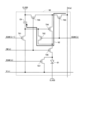
次に、表示部200内の画素回路20の構成について説明する。図1は、第n行第m列の画素回路20の構成を示す回路図である。この画素回路20は、表示素子(電流によって駆動される表示素子)としての1個の有機EL素子(有機発光ダイオード)21と、7個のトランジスタ(典型的には薄膜トランジスタ)T1~T7(第1初期化トランジスタT1、閾値電圧補償トランジスタT2、書き込み制御トランジスタT3、駆動トランジスタT4、第1発光制御トランジスタT5、第2発光制御トランジスタT6、第2初期化トランジスタT7)と、1個の保持キャパシタC1とを含んでいる。保持キャパシタC1は、2つの電極(第1電極および第2電極)からなる容量素子である。トランジスタT1~T7は、nチャネル型のトランジスタである。<1.2 Pixel circuit configuration>
Next, the configuration of the
図1に示した構成に関し、第1初期化トランジスタT1の第2導通端子、閾値電圧補償トランジスタT2の第1導通端子、駆動トランジスタT4の制御端子、および保持キャパシタC1の第1電極に接続されたノードを「第1制御ノード」という。第1制御ノードには符号NGを付す。また、書き込み制御トランジスタT3の第2導通端子、第2発光制御トランジスタT6の第1導通端子、および保持キャパシタC1の第2電極に接続されたノードを「第2制御ノード」という。第2制御ノードには符号NAを付す。 Regarding the configuration shown in FIG. 1, the second conduction terminal of the first initialization transistor T1, the first conduction terminal of the threshold voltage compensation transistor T2, the control terminal of the drive transistor T4, and the first electrode of the holding capacitor C1 are connected. The node is referred to as a "first control node." The first control node is designated by the symbol NG. Further, a node connected to the second conduction terminal of the write control transistor T3, the first conduction terminal of the second light emission control transistor T6, and the second electrode of the holding capacitor C1 is referred to as a "second control node." The second control node is designated by the symbol NA.
第1初期化トランジスタT1については、制御端子は(n-1)行目の走査信号線SCAN(n-1)に接続され、第1導通端子はハイレベル電源線と第1発光制御トランジスタT5の第1導通端子とに接続され、第2導通端子は第1制御ノードNGに接続されている。閾値電圧補償トランジスタT2については、制御端子はn行目の走査信号線SCAN(n)に接続され、第1導通端子は第1制御ノードNGに接続され、第2導通端子は駆動トランジスタT4の第1導通端子と第1発光制御トランジスタT5の第2導通端子に接続されている。書き込み制御トランジスタT3については、制御端子はn行目の走査信号線SCAN(n)に接続され、第1導通端子はm列目のデータ信号線D(m)に接続され、第2導通端子は第2制御ノードNAに接続されている。駆動トランジスタT4については、制御端子は第1制御ノードNGに接続され、第1導通端子は閾値電圧補償トランジスタT2の第2導通端子と第1発光制御トランジスタT5の第2導通端子とに接続され、第2導通端子は第2発光制御トランジスタT6の第2導通端子と第2初期化トランジスタT7の第1導通端子と有機EL素子21のアノード端子(第1端子)とに接続されている。
Regarding the first initialization transistor T1, the control terminal is connected to the (n-1)th row scanning signal line SCAN (n-1), and the first conduction terminal is connected to the high-level power supply line and the first light emission control transistor T5. The second conduction terminal is connected to the first control node NG. As for the threshold voltage compensation transistor T2, the control terminal is connected to the n-th scanning signal line SCAN(n), the first conduction terminal is connected to the first control node NG, and the second conduction terminal is connected to the scan signal line SCAN(n) of the n-th row. 1 conduction terminal and a second conduction terminal of the first light emission control transistor T5. Regarding the write control transistor T3, the control terminal is connected to the nth row scanning signal line SCAN(n), the first conduction terminal is connected to the mth column data signal line D(m), and the second conduction terminal is connected to the mth column data signal line D(m). It is connected to the second control node NA. As for the drive transistor T4, the control terminal is connected to the first control node NG, the first conduction terminal is connected to the second conduction terminal of the threshold voltage compensation transistor T2 and the second conduction terminal of the first light emission control transistor T5, The second conduction terminal is connected to the second conduction terminal of the second light emission control transistor T6, the first conduction terminal of the second initialization transistor T7, and the anode terminal (first terminal) of the
第1発光制御トランジスタT5については、制御端子はn行目の発光制御線EM(n)に接続され、第1導通端子はハイレベル電源線と第1初期化トランジスタT1の第1導通端子とに接続され、第2導通端子は閾値電圧補償トランジスタT2の第2導通端子と駆動トランジスタT4の第1導通端子とに接続されている。第2発光制御トランジスタT6については、制御端子はn行目の発光制御線EM(n)に接続され、第1導通端子は第2制御ノードNAに接続され、第2導通端子は駆動トランジスタT4の第2導通端子と第2初期化トランジスタT7の第1導通端子と有機EL素子21のアノード端子とに接続されている。第2初期化トランジスタT7については、制御端子はn行目の走査信号線SCAN(n)に接続され、第1導通端子は駆動トランジスタT4の第2導通端子と第2発光制御トランジスタT6の第2導通端子と有機EL素子21のアノード端子とに接続され、第2導通端子は基準電源線に接続されている。保持キャパシタC1については、第1電極は第1制御ノードNGに接続され、第2電極は第2制御ノードNAに接続されている。有機EL素子21については、アノード端子は駆動トランジスタT4の第2導通端子と第2発光制御トランジスタT6の第2導通端子と第2初期化トランジスタT7の第1導通端子とに接続され、カソード端子(第2端子)はローレベル電源線に接続されている。
Regarding the first light emission control transistor T5, the control terminal is connected to the nth row light emission control line EM(n), and the first conduction terminal is connected to the high level power supply line and the first conduction terminal of the first initialization transistor T1. The second conduction terminal is connected to the second conduction terminal of the threshold voltage compensation transistor T2 and the first conduction terminal of the drive transistor T4. Regarding the second light emission control transistor T6, the control terminal is connected to the nth row light emission control line EM(n), the first conduction terminal is connected to the second control node NA, and the second conduction terminal is connected to the drive transistor T4. It is connected to the second conduction terminal, the first conduction terminal of the second initialization transistor T7, and the anode terminal of the
本実施形態においては、第1初期化トランジスタT1、閾値電圧補償トランジスタT2、および第2初期化トランジスタT7には酸化物TFTが採用され、書き込み制御トランジスタT3、駆動トランジスタT4、第1発光制御トランジスタT5、および第2発光制御トランジスタT6にはLTPS-TFTが採用されている。 In this embodiment, oxide TFTs are adopted as the first initialization transistor T1, the threshold voltage compensation transistor T2, and the second initialization transistor T7, and the write control transistor T3, the drive transistor T4, and the first light emission control transistor T5. , and the second light emission control transistor T6 are LTPS-TFTs.
なお、酸化物TFTのチャネル層を形成する酸化物半導体は、本実施形態においては、インジウム、ガリウム、亜鉛、および酸素によって構成されている。但し、これには限定されない。 Note that the oxide semiconductor forming the channel layer of the oxide TFT is made of indium, gallium, zinc, and oxygen in this embodiment. However, it is not limited to this.
<1.3 駆動方法(画素回路の動作)>
次に、図3を参照しつつ、図1に示した画素回路20の動作について説明する。期間P1よりも前の期間および期間P5以降の期間が、この画素回路20内の有機EL素子21についての発光期間である。発光制御信号EMおよび走査信号SCANに関し、ハイレベルがオンレベルに相当し、ローレベルがオフレベルに相当する。なお、第2制御ノードNAおよび第1制御ノードNGの電圧の変化はデータ信号D(m)に依存するので、図3に示す第2制御ノードNAおよび第1制御ノードNGの電圧波形は一例である。また、図3の期間P1~P5における各トランジスタ(但し、駆動トランジスタT4を除く)の状態(オン/オフ状態)の推移を図4に示している。
<1.3 Driving method (operation of pixel circuit)>
Next, the operation of the
期間P1よりも前の期間には、発光制御信号EM(n)はハイレベルとなっていて、走査信号SCAN(n),SCAN(n-1)はローレベルとなっている。このとき、第1発光制御トランジスタT5および第2発光制御トランジスタT6はオン状態となっている。第2発光制御トランジスタT6がオン状態となっているので、駆動トランジスタT4の制御端子-第2導通端子間の電圧は保持キャパシタC1の充電電圧に等しくなっている。また、第1発光制御トランジスタT5がオン状態となっているので、保持キャパシタC1の充電電圧の大きさに応じて駆動電流が有機EL素子21に供給されている。これにより、有機EL素子21は駆動電流の大きさに応じて発光している。
In a period before the period P1, the light emission control signal EM(n) is at a high level, and the scanning signals SCAN(n) and SCAN(n-1) are at a low level. At this time, the first light emission control transistor T5 and the second light emission control transistor T6 are in the on state. Since the second light emission control transistor T6 is in the on state, the voltage between the control terminal and the second conduction terminal of the drive transistor T4 is equal to the charging voltage of the holding capacitor C1. Furthermore, since the first light emission control transistor T5 is in the on state, a drive current is supplied to the
期間P1になると、発光制御信号EM(n)がハイレベルからローレベルに変化する。これにより、第1発光制御トランジスタT5および第2発光制御トランジスタT6がオフ状態となる。その結果、有機EL素子21への駆動電流の供給が遮断され、有機EL素子21は消灯状態となる。
In period P1, the light emission control signal EM(n) changes from high level to low level. As a result, the first light emission control transistor T5 and the second light emission control transistor T6 are turned off. As a result, the supply of drive current to the
期間P2になると、走査信号SCAN(n-1)がローレベルからハイレベルに変化する。これにより、第1初期化トランジスタT1がオン状態となり、図5で符号61を付した矢印で示すように第1制御ノードNGに電流が供給される。その結果、保持キャパシタC1が充電され、第1制御ノードNGの電圧が上昇する。これにより、第1制御ノードNGの電圧はハイレベル電源電圧ELVDDに等しくなる。以上のように、期間P2には、第1制御ノードNGの電圧(すなわち、駆動トランジスタT4のゲート電圧)が初期化される。
In period P2, the scanning signal SCAN (n-1) changes from low level to high level. As a result, the first initialization transistor T1 is turned on, and a current is supplied to the first control node NG as shown by the
期間P3になると、走査信号SCAN(n-1)がハイレベルからローレベルに変化する。これにより、第1初期化トランジスタT1がオフ状態となり、第1制御ノードNGの電圧の初期化は終了する。また、期間P3になると、走査信号SCAN(n)がローレベルからハイレベルに変化する。これにより、閾値電圧補償トランジスタT2、書き込み制御トランジスタT3、および第2初期化トランジスタT7がオン状態となる。書き込み制御トランジスタT3がオン状態となることによって、図6で符号62を付した矢印で示すように、データ信号D(m)が書き込み制御トランジスタT3を介して第2制御ノードNAに与えられる。これにより、データ信号D(m)に応じて、第2制御ノードNAの電圧が変化する。このとき、第2制御ノードNAの電圧は、上昇する場合もあるし、低下する場合もあるし、維持される場合もある。ところで、第2制御ノードNA-第1制御ノードNG間には保持キャパシタC1が設けられている。従って、第2制御ノードNAの電圧の変化に応じて第1制御ノードNGの電圧も変化する。また、閾値電圧補償トランジスタT2および第2初期化トランジスタT7がオン状態となることによって、図6で符号63を付した矢印で示すように、第1制御ノードNGから基準電源線へと電流が流れる。これにより、第1制御ノードNGの電圧は徐々に低下する。そして、駆動トランジスタT4の制御端子-第2導通端子間の電圧が当該駆動トランジスタT4の閾値電圧に等しくなると、駆動トランジスタT4の第1導通端子-第2導通端子間に電流が流れなくなり、第1制御ノードNGの電圧の低下が止まる。具体的には、第1制御ノードNGの電圧は、基準電圧Vsusと駆動トランジスタT4の閾値電圧Vthとの和に等しくなるまで低下する。このとき、有機EL素子21のアノード電圧は基準電圧Vsusに等しくなっている。すなわち、期間P3には、有機EL素子21のアノード電圧が基準電圧Vsusに基づいて初期化される。
In period P3, the scanning signal SCAN(n-1) changes from high level to low level. As a result, the first initialization transistor T1 is turned off, and the initialization of the voltage of the first control node NG is completed. Furthermore, in period P3, the scanning signal SCAN(n) changes from low level to high level. This turns on the threshold voltage compensation transistor T2, the write control transistor T3, and the second initialization transistor T7. By turning on the write control transistor T3, the data signal D(m) is applied to the second control node NA via the write control transistor T3, as shown by the
期間P4になると、走査信号SCAN(n)がハイレベルからローレベルに変化する。これにより、閾値電圧補償トランジスタT2、書き込み制御トランジスタT3、および第2初期化トランジスタT7がオフ状態となる。期間P4には、第1制御ノードNGおよび第2制御ノードNAの電圧は、期間P3の終了時点における電圧が維持される。 In period P4, the scanning signal SCAN(n) changes from high level to low level. As a result, the threshold voltage compensation transistor T2, the write control transistor T3, and the second initialization transistor T7 are turned off. During the period P4, the voltages of the first control node NG and the second control node NA are maintained at the voltages at the end of the period P3.
期間P5になると、発光制御信号EM(n)がローレベルからハイレベルに変化する。これにより、第2発光制御トランジスタT6がオン状態となり、駆動トランジスタT4の第2導通端子と第2制御ノードNAとの間が電気的に接続された状態となる。すなわち、駆動トランジスタT4の第2導通端子の電圧と第2制御ノードNAの電圧とが等しくなる。また、期間P5には、第1発光制御トランジスタT5がオン状態となる。以上より、駆動トランジスタT4の制御端子-第2導通端子間の電圧(保持キャパシタC1の充電電圧)の大きさに応じて、図7で符号64を付した矢印で示すように駆動電流が有機EL素子21に供給される。その結果、その駆動電流の大きさに応じて有機EL素子21が発光する。なお、有機EL素子21のアノード電圧は駆動電流の大きさに応じて変化し、第2制御ノードNAの電圧は有機EL素子21のアノード電圧に等しくなるように変化する。そして、第2制御ノードNAの電圧の変化に応じて第1制御ノードNGの電圧も変化する。
In period P5, the light emission control signal EM(n) changes from low level to high level. As a result, the second light emission control transistor T6 is turned on, and the second conduction terminal of the drive transistor T4 and the second control node NA are electrically connected. That is, the voltage at the second conduction terminal of the drive transistor T4 and the voltage at the second control node NA become equal. Furthermore, during the period P5, the first light emission control transistor T5 is turned on. From the above, depending on the magnitude of the voltage between the control terminal and the second conduction terminal of the drive transistor T4 (the charging voltage of the holding capacitor C1), the drive current changes as shown by the
その後、発光制御信号EM(n)がハイレベルからローレベルに変化するまでの期間を通じて、駆動電流の大きさに応じて有機EL素子21が発光する状態が継続される。
After that, the
ここで、電圧の設定や電圧の変化の具体例について説明する。例えば、ハイレベル電源電圧ELVDDは11.5Vに設定され、ローレベル電源電圧ELVSSおよび基準電圧Vsusは2.5Vに設定され、走査信号SCANおよび発光制御信号EMのハイレベル側の電圧は14.5Vに設定され、走査信号SCANおよび発光制御信号EMのローレベル側の電圧は-3.5Vに設定される。また、データ信号Dの電圧は1V~6Vの範囲内で設定される。これに関し、白色に対応する電圧が1Vであり、黒色に対応する電圧が6Vである。なお、駆動トランジスタT4の閾値電圧は4Vになっていると仮定する。また、データ信号Dの電圧が白色に対応する電圧(1V)である時には発光期間中の有機EL素子21のアノード・カソード間電圧Voledが4Vになると仮定し、データ信号Dの電圧が黒色に対応する電圧(6V)である時には発光期間中の有機EL素子21のアノード・カソード間電圧Voledが0Vになると仮定する。
Here, specific examples of voltage settings and voltage changes will be described. For example, the high level power supply voltage ELVDD is set to 11.5V, the low level power supply voltage ELVSS and the reference voltage Vsus are set to 2.5V, and the high level side voltages of the scanning signal SCAN and the light emission control signal EM are 14.5V. The voltage on the low level side of the scan signal SCAN and the light emission control signal EM is set to -3.5V. Further, the voltage of the data signal D is set within the range of 1V to 6V. In this regard, the voltage corresponding to white is 1V, and the voltage corresponding to black is 6V. Note that it is assumed that the threshold voltage of the drive transistor T4 is 4V. Further, when the voltage of the data signal D is a voltage (1V) corresponding to white, it is assumed that the voltage Voled between the anode and cathode of the
まず、データ信号Dの電圧が白色に対応する電圧(1V)であるケースについて説明する。期間P2の終了時点には、データ信号Dの電圧に関わらず第1制御ノードNGの電圧が11.5Vとなる。 First, a case where the voltage of the data signal D is a voltage (1V) corresponding to white will be described. At the end of the period P2, the voltage of the first control node NG becomes 11.5V regardless of the voltage of the data signal D.
期間P3には、第2制御ノードNAの電圧が1Vとなる。また、上述したように、第1制御ノードNGの電圧は、基準電圧Vsusと駆動トランジスタT4の閾値電圧Vthとの和に等しくなるまで低下する。従って、期間P3の終了時点には、第1制御ノードNGの電圧は6.5Vとなる。上述したように、期間P4には、第1制御ノードNGおよび第2制御ノードNAの電圧は、期間P3の終了時点における電圧が維持される。以上より、期間P4の終了時点においては、第2制御ノードNAの電圧は1Vであり、第1制御ノードNGの電圧は6.5Vである。 During period P3, the voltage of the second control node NA becomes 1V. Further, as described above, the voltage of the first control node NG decreases until it becomes equal to the sum of the reference voltage Vsus and the threshold voltage Vth of the drive transistor T4. Therefore, at the end of period P3, the voltage of the first control node NG becomes 6.5V. As described above, during the period P4, the voltages of the first control node NG and the second control node NA are maintained at the voltages at the end of the period P3. From the above, at the end of period P4, the voltage at the second control node NA is 1V, and the voltage at the first control node NG is 6.5V.
期間P5には、第2制御ノードNAの電圧は、ローレベル電源電圧ELVSSと有機EL素子21のアノード・カソード間電圧Voledとの和に等しくなる。すなわち、期間P5における第2制御ノードNAの電圧VNAは下記の式(1)で表される。
VNA=ELVSS+Voled ・・・(1)
従って、期間P5には、第2制御ノードNAの電圧VNAは6.5Vとなる。During the period P5, the voltage of the second control node NA becomes equal to the sum of the low-level power supply voltage ELVSS and the anode-cathode voltage Voled of the
VNA=ELVSS+Voled...(1)
Therefore, during period P5, the voltage VNA of the second control node NA becomes 6.5V.
また、データ信号Dの電圧をVdataで表すと、期間P4から期間P5にかけての第2制御ノードNAの電圧の変化ΔVNAは下記の式(2)で表される。
ΔVNA=ELVSS+Voled-Vdata ・・・(2)
この例では、第2制御ノードNAの電圧の変化ΔVNAは5.5Vとなる。Further, when the voltage of the data signal D is expressed by Vdata, the change ΔVNA in the voltage of the second control node NA from the period P4 to the period P5 is expressed by the following equation (2).
ΔVNA=ELVSS+Voled-Vdata...(2)
In this example, the voltage change ΔVNA at the second control node NA is 5.5V.
上述したように、期間P5には、第2制御ノードNAの電圧の変化に応じて第1制御ノードNGの電圧も変化する。期間P4の終了時点における第1制御ノードNGの電圧は基準電圧Vsusと駆動トランジスタT4の閾値電圧Vthとの和に等しいので、期間P5における第1制御ノードNGの電圧VNGは下記の式(3)で表される。なお、kは第2制御ノードNAによって形成される容量全体の容量値に対する保持キャパシタC1の容量値の割合であって、ここでは「k=1」が成立すると仮定する。
VNG=Vsus+Vth+kΔVNA ・・・(3)
以上より、期間P5には、第1制御ノードNGの電圧VNGは12Vとなる。As described above, during the period P5, the voltage at the first control node NG also changes in accordance with the change in the voltage at the second control node NA. Since the voltage of the first control node NG at the end of the period P4 is equal to the sum of the reference voltage Vsus and the threshold voltage Vth of the drive transistor T4, the voltage VNG of the first control node NG during the period P5 is expressed by the following equation (3). It is expressed as Note that k is the ratio of the capacitance value of the holding capacitor C1 to the capacitance value of the entire capacitor formed by the second control node NA, and it is assumed here that "k=1" holds true.
VNG=Vsus+Vth+kΔVNA...(3)
As described above, the voltage VNG of the first control node NG becomes 12V during the period P5.
期間P5における駆動トランジスタT4の第1導通端子-第2導通端子間の電圧Vgsは下記の式(4)で表される。
Vgs=VNG-VNA
=Vsus+Vth+kΔVNA-(ELVSS+Voled)
=Vsus+Vth+ELVSS+Voled-Vdata-(ELVSS+Voled)
=Vsus+Vth-Vdata ・・・(4)
この例では、駆動トランジスタT4の第1導通端子-第2導通端子間の電圧Vgsは5.5Vとなる。The voltage Vgs between the first conduction terminal and the second conduction terminal of the drive transistor T4 during the period P5 is expressed by the following equation (4).
Vgs=VNG-VNA
=Vsus+Vth+kΔVNA-(ELVSS+Voled)
=Vsus+Vth+ELVSS+Voled-Vdata-(ELVSS+Voled)
=Vsus+Vth-Vdata...(4)
In this example, the voltage Vgs between the first conduction terminal and the second conduction terminal of the drive transistor T4 is 5.5V.
期間P5以降の期間に有機EL素子21に流れる電流Ioledは、“Vgs≧Vth”が成立する時には下記の式(5)で表され、“Vgs<Vth”が成立する時には下記の式(6)で表される。


次に、データ信号Dの電圧が黒色に対応する電圧(6V)であるケースについて説明する。なお、上述したように、期間P2の終了時点には、データ信号Dの電圧に関わらず第1制御ノードNGの電圧が11.5Vとなる。 Next, a case will be described in which the voltage of the data signal D is a voltage (6V) corresponding to black. Note that, as described above, at the end of the period P2, the voltage of the first control node NG becomes 11.5V regardless of the voltage of the data signal D.
期間P3には、第2制御ノードNAの電圧が6Vとなる。また、上述したように、期間P3の終了時点には、第1制御ノードNGの電圧は6.5Vとなり、期間P4には、第1制御ノードNGおよび第2制御ノードNAの電圧は、期間P3の終了時点における電圧が維持される。以上より、期間P4の終了時点においては、第2制御ノードNAの電圧は6Vであり、第1制御ノードNGの電圧は6.5Vである。 During period P3, the voltage at the second control node NA becomes 6V. Further, as described above, at the end of the period P3, the voltage of the first control node NG becomes 6.5V, and in the period P4, the voltages of the first control node NG and the second control node NA become 6.5V during the period P3. The voltage at the end of is maintained. From the above, at the end of period P4, the voltage at the second control node NA is 6V, and the voltage at the first control node NG is 6.5V.
期間P5には、上式(1)より、第2制御ノードNAの電圧VNAは2.5Vとなる。期間P4から期間P5にかけての第2制御ノードNAの電圧の変化ΔVNAは、上式(2)より、-3.5Vとなる。また、期間P5には、上式(3)より、第1制御ノードNGの電圧VNGは3Vとなる。期間P5における駆動トランジスタT4の第1導通端子-第2導通端子間の電圧Vgsは、上式(4)より、0.5Vとなる。 In period P5, the voltage VNA of the second control node NA becomes 2.5V from the above equation (1). The change ΔVNA in the voltage of the second control node NA from the period P4 to the period P5 is -3.5V from the above equation (2). Further, during the period P5, the voltage VNG of the first control node NG becomes 3V according to the above equation (3). The voltage Vgs between the first conduction terminal and the second conduction terminal of the drive transistor T4 during the period P5 is 0.5V from the above equation (4).
期間P5以降の期間に有機EL素子21に流れる電流Ioledについては、データ信号Dの電圧が白色に対応する電圧(1V)であるケースと同様の式で表される(上式(5)および上式(6)を参照)。
The current Ioled flowing through the
<1.4 従来例との対比>
上述した米国特許第10304378号明細書に記載された構成(図8参照)によれば、例えば、図9で符号78を付した矢印で表される期間に、保持キャパシタCstへのデータ信号Vdataに応じた電圧の充電(書き込み)と、駆動トランジスタの閾値電圧のばらつきを補償するための補償処理とが行われる。但し、補償処理の開始時点にはNode3の電圧がデータ信号Vdataの電圧に設定されている必要がある。従って、信号Scan1をローレベルかつ信号Scan2をハイレベルとすることによってNode3の電圧をデータ信号Vdataの電圧に設定するための期間(図9で符号77を付した矢印で表される期間)が必要である。以上より、データ信号Vdataの電圧の変化開始時点から補償処理の終了時点(Node2の電圧が駆動トランジスタの閾値電圧に応じた大きさとなる時点)までの期間は比較的長くなる。これに対して、本実施形態によれば、図6から把握されるようにデータ信号Dの書き込みのための電流経路と補償処理のための電流経路とが全く別の経路となっているため、データ信号Dの電圧の変化開始時点に補償処理の動作を開始することができる。すなわち、図10で符号79を付した矢印で表される期間のように、データ信号Dの電圧の変化開始時点から補償処理の終了時点(第1制御ノードNGの電圧が駆動トランジスタの閾値電圧に応じた大きさとなる時点)までの期間は比較的短くなる。以上のように、米国特許第10304378号明細書に記載された構成によれば、本実施形態に係る構成と比較して、1水平期間(1H)の長さは少なくとも図9で符号77を付した矢印で表される期間だけ長くなる。換言すれば、本実施形態によれば、1水平期間(1H)の長さを短くすることができるので、従来よりも高速駆動が可能となる。<1.4 Comparison with conventional example>
According to the configuration described in the above-mentioned US Pat. No. 1,030,378 (see FIG. 8), for example, during the period indicated by the
<1.5 効果>
本実施形態によれば、画素回路20の構成に関し、書き込み制御トランジスタT3を介してデータ信号線Dに接続された第2制御ノードNAと駆動トランジスタT4の制御端子に接続された第1制御ノードNGとの間に保持キャパシタC1が設けられている。このような構成により、保持キャパシタC1の充電は駆動トランジスタT4を介さずに行われる。すなわち、保持キャパシタC1の充電は速やかに行われる。また、データ信号Dの電圧は閾値電圧補償トランジスタT2がオン状態からオフ状態に変化する時点(図10の時点ta)までに確定していれば良いので、データ信号Dの波形変化に大きな遅延が生じない限り表示品位は低下しない。さらに、駆動トランジスタT4にはLTPS-TFTが採用されているので、駆動トランジスタT4の閾値電圧を補償するための補償処理が行われる期間P3(図3参照)に第1制御ノードNGの充電が速やかに行われる。以上より、例えば駆動周波数を120Hzとするような高周波駆動(高速駆動)が行われても、良好な表示品位が維持される。また、第1制御ノードNGに導通端子が接続されたトランジスタ(詳しくは、第1制御ノードNGに第2導通端子が接続された第1初期化トランジスタT1および第1制御ノードNGに第1導通端子が接続された閾値電圧補償トランジスタT2)には、酸化物TFTが採用されている。それ故、それらのトランジスタでのリーク電流の発生が防止される。従って、例えば駆動周波数を1Hzとするような低周波駆動(低速駆動)が行われても、リーク電流に起因して表示品位が低下することはない。すなわち、良好な表示品位が維持される。以上より、本実施形態によれば、表示品位の低下を引き起こすことなく高周波駆動および低周波駆動の双方を可能ならしめる画素回路20を備えた有機EL表示装置が実現される。<1.5 Effects>
According to the present embodiment, regarding the configuration of the
<1.6 変形例>
第1の実施形態の変形例について説明する。但し、第1の実施形態と異なる点を中心に説明する。<1.6 Modification example>
A modification of the first embodiment will be described. However, the explanation will focus on the differences from the first embodiment.
図11は、第1の実施形態の変形例に係る有機EL表示装置の全体構成を示すブロック図である。本変形例においては、発光制御信号EMの論理反転信号を伝達する信号配線(以下、「リセット制御線」という。)が表示部200に配設されている。詳しくは、j本の発光制御線EM(1)~EM(j)と1対1で対応するように、j本のリセット制御線EMB(1)~EMB(j)が表示部200に配設されている。このように、本変形例においては、表示部200には、i本のデータ信号線D(1)~D(i)、(j+1)本の走査信号線SCAN(0)~SCAN(j)、およびj本の発光制御線EM(1)~EM(j)に加えて、j本のリセット制御線EMB(1)~EMB(j)が配設されている。なお、以下においては、j本のリセット制御線EMB(1)~EMB(j)によって伝達されるリセット制御信号(発光制御信号EMの論理反転信号)にも符号EMB(1)~EMB(j)を付す場合がある。
FIG. 11 is a block diagram showing the overall configuration of an organic EL display device according to a modification of the first embodiment. In this modification, a signal line (hereinafter referred to as a "reset control line") that transmits a logically inverted signal of the light emission control signal EM is arranged in the
図12は、第n行第m列の画素回路20の構成を示す回路図である。第1の実施形態(図1参照)と同様、この画素回路20は、1個の有機EL素子21と、7個のトランジスタ(典型的には薄膜トランジスタ)T1~T7(第1初期化トランジスタT1、閾値電圧補償トランジスタT2、書き込み制御トランジスタT3、駆動トランジスタT4、第1発光制御トランジスタT5、第2発光制御トランジスタT6、第2初期化トランジスタT7)と、1個の保持キャパシタC1とを含んでいる。本変形例においては、第2初期化トランジスタT7の制御端子がn行目のリセット制御線EMB(n)に接続されている。それ以外の点については、第1の実施形態と同様である。
FIG. 12 is a circuit diagram showing the configuration of the
第2初期化トランジスタT7がオン状態になると、有機EL素子21のアノード端子と基準電源線とが電気的に接続された状態となり、基準電圧Vsusに基づいて有機EL素子21のアノード電圧が初期化される。このように、リセット制御線EMBは、有機EL素子21のアノード端子の状態を初期化するための信号配線である。
When the second initialization transistor T7 is turned on, the anode terminal of the
なお、本変形例においても、第1初期化トランジスタT1、閾値電圧補償トランジスタT2、および第2初期化トランジスタT7には酸化物TFTが採用され、書き込み制御トランジスタT3、駆動トランジスタT4、第1発光制御トランジスタT5、および第2発光制御トランジスタT6にはLTPS-TFTが採用されている。 Note that also in this modification, oxide TFTs are adopted as the first initialization transistor T1, threshold voltage compensation transistor T2, and second initialization transistor T7, and the write control transistor T3, drive transistor T4, and first light emission control transistor LTPS-TFT is used for the transistor T5 and the second light emission control transistor T6.
図13を参照しつつ、図12に示した画素回路20の動作について説明する。なお、図13の期間P1~P5における各トランジスタ(但し、駆動トランジスタT4を除く)の状態(オン/オフ状態)の推移を図14に示している。
The operation of the
期間P1よりも前の期間については、第1の実施形態と同様である。なお、リセット制御信号EMB(n)はローレベルとなっている。期間P1には、第1の実施形態と同様、有機EL素子21は消灯状態となる。また、期間P1には、リセット制御信号EMB(n)がローレベルからハイレベルに変化する。これにより、第2初期化トランジスタT7がオン状態となり、図15で符号65を付した矢印で示すように電流が生じ、有機EL素子21のアノード電圧が基準電圧Vsusに基づいて初期化される。
The period before period P1 is the same as in the first embodiment. Note that the reset control signal EMB(n) is at a low level. During the period P1, the
期間P2には、第1の実施形態と同様、第1初期化トランジスタT1がオン状態となることによって第1制御ノードNGの電圧(すなわち、駆動トランジスタT4のゲート電圧)が初期化される。 In the period P2, as in the first embodiment, the first initialization transistor T1 is turned on, so that the voltage of the first control node NG (that is, the gate voltage of the drive transistor T4) is initialized.
期間P3には、リセット制御信号EMB(n)はハイレベルで維持され、走査信号SCAN(n)がローレベルからハイレベルに変化する。これにより、第2初期化トランジスタT7はオン状態で維持され、閾値電圧補償トランジスタT2および書き込み制御トランジスタT3がオン状態となる。以上より、第1の実施形態と同様、図16で符号66を付した矢印で示すようにデータ信号D(m)が書き込み制御トランジスタT3を介して第2制御ノードNAに与えられ、また、図16で符号67を付した矢印で示すように第1制御ノードNGから基準電源線へと電流が流れる。これにより、データ信号D(m)に応じて第2制御ノードNAの電圧が変化し、また、第1制御ノードNGの電圧は基準電圧Vsusと駆動トランジスタT4の閾値電圧Vthとの和に等しくなる。
During period P3, the reset control signal EMB(n) is maintained at a high level, and the scanning signal SCAN(n) changes from a low level to a high level. As a result, the second initialization transistor T7 is maintained in an on state, and the threshold voltage compensation transistor T2 and write control transistor T3 are turned on. As described above, as in the first embodiment, the data signal D(m) is applied to the second control node NA via the write control transistor T3 as shown by the
期間P4には、第1の実施形態と同様、第1制御ノードNGおよび第2制御ノードNAの電圧は、期間P3の終了時点における電圧が維持される。 During the period P4, as in the first embodiment, the voltages of the first control node NG and the second control node NA are maintained at the voltages at the end of the period P3.
期間P5になると、リセット制御信号EMB(n)がハイレベルからローレベルに変化する。これにより、第2初期化トランジスタT7がオフ状態となる。また、期間P5には、発光制御信号EM(n)がローレベルからハイレベルに変化する。これにより、第1発光制御トランジスタT5および第2発光制御トランジスタT6がオン状態となり、第1の実施形態と同様、駆動トランジスタT4の制御端子-第2導通端子間の電圧(保持キャパシタC1の充電電圧)の大きさに応じて、図17で符号68を付した矢印で示すように駆動電流が有機EL素子21に供給される。その結果、その駆動電流の大きさに応じて有機EL素子21が発光する。
In period P5, the reset control signal EMB(n) changes from high level to low level. This turns the second initialization transistor T7 off. Further, during period P5, the light emission control signal EM(n) changes from low level to high level. As a result, the first light emission control transistor T5 and the second light emission control transistor T6 are turned on, and as in the first embodiment, the voltage between the control terminal of the drive transistor T4 and the second conduction terminal (the charging voltage of the holding capacitor C1 ), a drive current is supplied to the
その後、発光制御信号EM(n)がハイレベルからローレベルに変化するまでの期間を通じて、駆動電流の大きさに応じて有機EL素子21が発光する状態が継続される。
After that, the
本変形例によれば、第1の実施形態と比較して低周波駆動が行われている際のフリッカの発生が抑制されるという効果が得られる。これについて、図18および図19を参照しつつ、以下に説明する。図18は、第1の実施形態における低周波駆動時の動作について説明するための波形図であり、図19は、本変形例における低周波駆動時の動作について説明するための波形図である。ここでは、n行目の画素回路20に着目し、白色表示が行われていると仮定する。図18および図19では、表示画面の更新(画素回路20内へのデータ信号Dの書き込み)が行われるフレーム期間であるリフレッシュフレームを符号RFで表し、表示画面の更新が行われないフレーム期間であるノンリフレッシュフレームを符号NRFで表している。なお、発光制御信号EM(n)がハイレベルとなっている期間が発光期間であり、発光制御信号EM(n)がローレベルとなっている期間が非発光期間である。
According to this modification, compared to the first embodiment, it is possible to obtain an effect that flicker generation is suppressed when low frequency driving is performed. This will be explained below with reference to FIGS. 18 and 19. FIG. 18 is a waveform diagram for explaining the operation during low frequency driving in the first embodiment, and FIG. 19 is a waveform diagram for explaining the operation during low frequency driving in this modification. Here, we focus on the
まず、第1の実施形態に着目する(図18参照)。リフレッシュフレームRFの非発光期間には、走査信号SCAN(n)がハイレベルとなる期間があるので、第2初期化トランジスタT7がオン状態となることによって有機EL素子21のアノード電圧が速やかに低下する。従って、輝度は速やかに低下する。また、このように有機EL素子21のアノード電圧が初期化されていることから、リフレッシュフレームRFにおいて非発光期間から発光期間に遷移した際に輝度は緩やかに上昇する。ノンリフレッシュフレームNRFの非発光期間には、第2初期化トランジスタT7はオフ状態で維持されるので、有機EL素子21のアノード電圧はそのまま維持される。そして、第1発光制御トランジスタT5がオフ状態となることのみによって輝度が低下する。従って、輝度は緩やかに低下する。また、有機EL素子21のアノード電圧がそのまま維持されていることから、ノンリフレッシュフレームNRFにおいて非発光期間から発光期間に遷移した際には輝度は速やかに上昇する。以上より、リフレッシュフレームRFとノンリフレッシュフレームNRFとでは、輝度が所定レベル以下となっている期間の長さが異なる。より詳しくは、輝度が所定レベル以下となっている期間は、リフレッシュフレームRFにおいては図18で符号81を付した矢印で示されるように比較的長いのに対して、ノンリフレッシュフレームNRFにおいては図18で符号82を付した矢印で示されるように比較的短い。また、これに起因して、リフレッシュフレームRFの終了後に安定した輝度が得られるまでに数フレームを要する(図18で符号83,84を付した太点線を参照)。以上のことから、第1の実施形態においては低周波のフリッカの発生が懸念される。
First, attention will be paid to the first embodiment (see FIG. 18). During the non-emission period of the refresh frame RF, there is a period in which the scanning signal SCAN(n) is at a high level, so the second initialization transistor T7 is turned on, and the anode voltage of the
次に、本変形例に着目する(図19参照)。リフレッシュフレームRFにおいてもノンリフレッシュフレームNRFにおいても、非発光期間にはリセット制御信号EMB(n)がハイレベルとなることによって第2初期化トランジスタT7がオン状態になる。このため、リフレッシュフレームRFにおいてもノンリフレッシュフレームNRFにおいても、発光期間から非発光期間に遷移する際には輝度は速やかに低下し、非発光期間から発光期間に遷移する際には輝度は緩やかに上昇する。すなわち、リフレッシュフレームRFとノンリフレッシュフレームNRFとで輝度は同じように変化する。従って、第1の実施形態とは異なり、輝度が所定レベル以下となっている期間の長さはリフレッシュフレームRFとノンリフレッシュフレームNRFとで等しくなる。また、第1の実施形態とは異なり、1フレーム期間毎に駆動トランジスタT4にオンバイアスストレスが掛かるので、駆動トランジスタT4のヒステリシスの影響を除去することが可能となる。以上より、本変形例によれば、低周波のフリッカの発生が抑制される。 Next, we will focus on this modification (see FIG. 19). In both the refresh frame RF and the non-refresh frame NRF, the second initialization transistor T7 is turned on by the reset control signal EMB(n) being at a high level during the non-emission period. Therefore, in both refresh frame RF and non-refresh frame NRF, the brightness decreases quickly when transitioning from a light emission period to a non-light emission period, and the brightness gradually decreases when transitioning from a non-light emission period to a light emission period. Rise. That is, the brightness changes in the same way between the refresh frame RF and the non-refresh frame NRF. Therefore, unlike the first embodiment, the length of the period during which the luminance is below a predetermined level is equal between the refresh frame RF and the non-refresh frame NRF. Further, unlike the first embodiment, since on-bias stress is applied to the drive transistor T4 every frame period, it is possible to eliminate the influence of hysteresis of the drive transistor T4. As described above, according to this modification, the occurrence of low frequency flicker is suppressed.
<2.第2の実施形態>
<2.1 全体構成>
図20は、第2の実施形態に係る有機EL表示装置の全体構成を示すブロック図である。本実施形態における全体構成は、第1の実施形態における全体構成(図2参照)とほぼ同様である。但し、本実施形態においては、初期化電圧Viniを供給する電源線(以下、「初期化電源線」という。)が表示部200に配設されている。初期化電圧Viniは、図示しない電源回路から供給される。<2. Second embodiment>
<2.1 Overall configuration>
FIG. 20 is a block diagram showing the overall configuration of an organic EL display device according to the second embodiment. The overall configuration of this embodiment is almost the same as the overall configuration of the first embodiment (see FIG. 2). However, in the present embodiment, a power line (hereinafter referred to as "initialization power line") that supplies the initialization voltage Vini is provided in the
<2.2 画素回路の構成>
図21は、第n行第m列の画素回路20の構成を示す回路図である。この画素回路20は、表示素子(電流によって駆動される表示素子)としての1個の有機EL素子(有機発光ダイオード)22と、7個のトランジスタ(典型的には薄膜トランジスタ)M1~M7(第1初期化トランジスタM1、閾値電圧補償トランジスタM2、書き込み制御トランジスタM3、駆動トランジスタM4、第1発光制御トランジスタM5、第2発光制御トランジスタM6、第2初期化トランジスタM7)と、1個の保持キャパシタC2とを含んでいる。保持キャパシタC2は、2つの電極(第1電極および第2電極)からなる容量素子である。閾値電圧補償トランジスタM2、書き込み制御トランジスタM3、第2発光制御トランジスタM6、および第2初期化トランジスタM7は、nチャネル型のトランジスタである。第1初期化トランジスタM1、駆動トランジスタM4,および第1発光制御トランジスタM5は、pチャネル型のトランジスタである。<2.2 Pixel circuit configuration>
FIG. 21 is a circuit diagram showing the configuration of the
図21に示した構成に関し、閾値電圧補償トランジスタM2の第1導通端子、駆動トランジスタM4の制御端子、第2初期化トランジスタM7の第1導通端子、および保持キャパシタC2の第1電極に接続されたノードを「第1制御ノード」という。また、第1初期化トランジスタM1の第2導通端子、書き込み制御トランジスタM3の第2導通端子、および保持キャパシタC2の第2電極に接続されたノードを「第2制御ノード」という。第1の実施形態と同様、第1制御ノードには符号NGを付し、第2制御ノードには符号NAを付す。 With respect to the configuration shown in FIG. 21, the first conduction terminal of the threshold voltage compensation transistor M2, the control terminal of the drive transistor M4, the first conduction terminal of the second initialization transistor M7, and the first electrode of the holding capacitor C2 are connected. The node is referred to as a "first control node." Further, a node connected to the second conduction terminal of the first initialization transistor M1, the second conduction terminal of the write control transistor M3, and the second electrode of the holding capacitor C2 is referred to as a "second control node." As in the first embodiment, the first control node is designated by the symbol NG, and the second control node is designated by the symbol NA.
第1初期化トランジスタM1については、制御端子はn行目の走査信号線SCAN(n)に接続され、第1導通端子は基準電源線に接続され、第2導通端子は第2制御ノードNAに接続されている。閾値電圧補償トランジスタM2については、制御端子はn行目の走査信号線SCAN(n)に接続され、第1導通端子は第1制御ノードNGに接続され、第2導通端子は駆動トランジスタM4の第2導通端子と第1発光制御トランジスタM5の第1導通端子に接続されている。書き込み制御トランジスタM3については、制御端子はn行目の走査信号線SCAN(n)に接続され、第1導通端子はm列目のデータ信号線D(m)に接続され、第2導通端子は第2制御ノードNAに接続されている。駆動トランジスタM4については、制御端子は第1制御ノードNGに接続され、第1導通端子はハイレベル電源線に接続され、第2導通端子は閾値電圧補償トランジスタM2の第2導通端子と第1発光制御トランジスタM5の第1導通端子とに接続されている。 Regarding the first initialization transistor M1, the control terminal is connected to the n-th scanning signal line SCAN(n), the first conduction terminal is connected to the reference power supply line, and the second conduction terminal is connected to the second control node NA. It is connected. As for the threshold voltage compensation transistor M2, the control terminal is connected to the n-th scanning signal line SCAN(n), the first conduction terminal is connected to the first control node NG, and the second conduction terminal is connected to the scan signal line SCAN(n) of the n-th row. 2 conduction terminal and the first conduction terminal of the first light emission control transistor M5. Regarding the write control transistor M3, the control terminal is connected to the nth row scanning signal line SCAN(n), the first conduction terminal is connected to the mth column data signal line D(m), and the second conduction terminal is connected to the mth column data signal line D(m). It is connected to the second control node NA. Regarding the drive transistor M4, the control terminal is connected to the first control node NG, the first conduction terminal is connected to the high level power supply line, and the second conduction terminal is connected to the second conduction terminal of the threshold voltage compensation transistor M2 and the first light emission terminal. The first conduction terminal of the control transistor M5 is connected to the first conduction terminal of the control transistor M5.
第1発光制御トランジスタM5については、制御端子はn行目の発光制御線EM(n)に接続され、第1導通端子は閾値電圧補償トランジスタM2の第2導通端子と駆動トランジスタM4の第2導通端子とに接続され、第2導通端子は第2発光制御トランジスタM6の第1導通端子と有機EL素子21のアノード端子(第1端子)とに接続されている。第2発光制御トランジスタM6については、制御端子はn行目の発光制御線EM(n)に接続され、第1導通端子は第1発光制御トランジスタM5の第2導通端子と有機EL素子21のアノード端子とに接続され、第2導通端子は第2初期化トランジスタM7の第2導通端子と初期化電源線とに接続されている。第2初期化トランジスタM7については、制御端子は(n-1)行目の走査信号線SCAN(n-1)に接続され、第1導通端子は第1制御ノードNGに接続され、第2導通端子は第2発光制御トランジスタM6の第2導通端子と初期化電源線とに接続されている。保持キャパシタC2については、第1電極は第1制御ノードNGに接続され、第2電極は第2制御ノードNAに接続されている。有機EL素子21については、アノード端子は第1発光制御トランジスタM5の第2導通端子と第2発光制御トランジスタM6の第1導通端子とに接続され、カソード端子(第2端子)はローレベル電源線に接続されている。
Regarding the first light emission control transistor M5, the control terminal is connected to the nth row light emission control line EM(n), and the first conduction terminal is connected to the second conduction terminal of the threshold voltage compensation transistor M2 and the second conduction terminal of the drive transistor M4. The second conduction terminal is connected to the first conduction terminal of the second light emission control transistor M6 and the anode terminal (first terminal) of the
本実施形態においては、閾値電圧補償トランジスタM2、書き込み制御トランジスタM3、第2発光制御トランジスタM6、および第2初期化トランジスタM7には酸化物TFTが採用され、第1初期化トランジスタM1、駆動トランジスタM4、および第1発光制御トランジスタM5にはLTPS-TFTが採用されている。 In this embodiment, oxide TFTs are adopted as the threshold voltage compensation transistor M2, the write control transistor M3, the second light emission control transistor M6, and the second initialization transistor M7, and the first initialization transistor M1 and the drive transistor M4 are , and the first light emission control transistor M5 are LTPS-TFTs.
<2.3 駆動方法(画素回路の動作)>
次に、図22を参照しつつ、図21に示した画素回路20の動作について説明する。図22の期間P11~P15における各トランジスタ(但し、駆動トランジスタM4を除く)の状態(オン/オフ状態)の推移を図23に示している。<2.3 Driving method (operation of pixel circuit)>
Next, the operation of the
期間P11よりも前の期間には、発光制御信号EM(n)、走査信号SCAN(n)、および走査信号SCAN(n-1)はローレベルとなっている。このとき、閾値電圧補償トランジスタM2、第2発光制御トランジスタM6、および第2初期化トランジスタM7はオフ状態となっていて、第1発光制御トランジスタM5はオン状態となっている。従って、駆動トランジスタM4の制御端子-第2導通端子間の電圧の大きさに応じて駆動電流が有機EL素子22に供給されている。これにより、有機EL素子22は駆動電流の大きさに応じて発光している。なお、書き込み制御トランジスタM3はオフ状態かつ第1初期化トランジスタM1はオン状態となっているので、第2制御ノードNAの電圧は基準電圧Vsusに等しくなっている。
In a period before the period P11, the light emission control signal EM(n), the scanning signal SCAN(n), and the scanning signal SCAN(n-1) are at a low level. At this time, the threshold voltage compensation transistor M2, the second light emission control transistor M6, and the second initialization transistor M7 are in an off state, and the first light emission control transistor M5 is in an on state. Therefore, a drive current is supplied to the
期間P11になると、発光制御信号EM(n)がローレベルからハイレベルに変化する。これにより、第1発光制御トランジスタM5がオフ状態となり、第2発光制御トランジスタM6がオン状態となる。第1発光制御トランジスタM5がオフ状態となることによって、有機EL素子22への駆動電流の供給が遮断され、有機EL素子22は消灯状態となる。また、第2発光制御トランジスタM6がオン状態となることによって、有機EL素子22のアノード電圧が初期化電圧Viniに基づいて初期化される。
In period P11, the light emission control signal EM(n) changes from low level to high level. As a result, the first light emission control transistor M5 is turned off, and the second light emission control transistor M6 is turned on. When the first light emission control transistor M5 is turned off, the supply of drive current to the
期間P12になると、走査信号SCAN(n-1)がローレベルからハイレベルに変化する。これにより、第2初期化トランジスタM7がオン状態となり、図24で符号71を付した矢印で示すように、第1制御ノードNGから初期化電源線へと電流が流れる。その結果、第1制御ノードNGの電圧は初期化電圧Viniに等しくなる。以上のように、期間P12には、第1制御ノードNGの電圧(すなわち、駆動トランジスタM4のゲート電圧)が初期化される。
In period P12, the scanning signal SCAN(n-1) changes from low level to high level. As a result, the second initialization transistor M7 is turned on, and a current flows from the first control node NG to the initialization power supply line as shown by the
期間P13になると、走査信号SCAN(n-1)がハイレベルからローレベルに変化する。これにより、第2初期化トランジスタM7がオフ状態となり、第1制御ノードNGの電圧の初期化は終了する。また、期間P13になると、走査信号SCAN(n)がローレベルからハイレベルに変化する。これにより、第1初期化トランジスタM1がオフ状態となり、閾値電圧補償トランジスタM2および書き込み制御トランジスタM3がオン状態となる。第1初期化トランジスタM1がオフ状態かつ書き込み制御トランジスタM3がオン状態となることによって、図25で符号72を付した矢印で示すように、データ信号D(m)が書き込み制御トランジスタM3を介して第2制御ノードNAに与えられる。これにより、データ信号D(m)に応じて、第2制御ノードNAの電圧が上昇する。ところで、第2制御ノードNA-第1制御ノードNG間には保持キャパシタC2が設けられている。従って、第2制御ノードNAの電圧の上昇に応じて第1制御ノードNGの電圧も上昇する。また、閾値電圧補償トランジスタM2がオン状態となることによって、図25で符号73を付した矢印で示すように、ハイレベル電源線から第1制御ノードNGへと電流が流れる。これにより、第1制御ノードNGの電圧は徐々に上昇する。そして、駆動トランジスタM4の制御端子-第2導通端子間の電圧が当該駆動トランジスタM4の閾値電圧に等しくなると、駆動トランジスタM4の第1導通端子-第2導通端子間に電流が流れなくなり、第1制御ノードNGの電圧の上昇が止まる。具体的には、第1制御ノードNGの電圧は、ハイレベル電源電圧ELVDDと駆動トランジスタM4の閾値電圧Vthとの和に等しくなるまで上昇する。以上のようにして、期間P13には、データ信号D(m)に応じて保持キャパシタC2が充電される。
In period P13, the scanning signal SCAN (n-1) changes from high level to low level. As a result, the second initialization transistor M7 is turned off, and the initialization of the voltage of the first control node NG is completed. Furthermore, in period P13, the scanning signal SCAN(n) changes from low level to high level. As a result, the first initialization transistor M1 is turned off, and the threshold voltage compensation transistor M2 and write control transistor M3 are turned on. As the first initialization transistor M1 is turned off and the write control transistor M3 is turned on, the data signal D(m) is transmitted through the write control transistor M3 as shown by the
期間P14になると、走査信号SCAN(n)がハイレベルからローレベルに変化する。これにより、閾値電圧補償トランジスタM2および書き込み制御トランジスタM3がオフ状態となり、第1初期化トランジスタM1がオン状態となる。書き込み制御トランジスタM3がオフ状態かつ第1初期化トランジスタM1がオン状態となることによって、図26で符号74を付した矢印で示すように、第2制御ノードNAから基準電源線へと電流が流れる。これにより、第2制御ノードNAの電圧は、基準電圧Vsusに等しくなるまで低下する。このとき、保持キャパシタC2の存在に起因して、第1制御ノードNGの電圧も低下する。
In period P14, the scanning signal SCAN(n) changes from high level to low level. As a result, the threshold voltage compensation transistor M2 and the write control transistor M3 are turned off, and the first initialization transistor M1 is turned on. When the write control transistor M3 is in the off state and the first initialization transistor M1 is in the on state, a current flows from the second control node NA to the reference power supply line, as shown by the
期間P15になると、発光制御信号EM(n)がハイレベルからローレベルに変化する。これにより、第2発光制御トランジスタM6がオフ状態となり、第1発光制御トランジスタM5がオン状態となる。その結果、駆動トランジスタM4の制御端子-第2導通端子間の電圧の大きさに応じて、図27で符号75を付した矢印で示すように駆動電流が有機EL素子22に供給される。これにより、有機EL素子22は駆動電流の大きさに応じて発光する。
In period P15, the light emission control signal EM(n) changes from high level to low level. As a result, the second light emission control transistor M6 is turned off, and the first light emission control transistor M5 is turned on. As a result, a drive current is supplied to the
その後、発光制御信号EM(n)がハイレベルからローレベルに変化するまでの期間を通じて、駆動電流の大きさに応じて有機EL素子22が発光する状態が継続される。
After that, the
<2.4 効果>
本実施形態によれば、画素回路20の構成に関し、書き込み制御トランジスタM3を介してデータ信号線Dに接続された第2制御ノードNAと駆動トランジスタM4の制御端子に接続された第1制御ノードNGとの間に保持キャパシタC2が設けられている。このような構成により、保持キャパシタC2の充電は駆動トランジスタM4を介さずに行われる。すなわち、保持キャパシタC2の充電は速やかに行われる。また、データ信号Dの電圧は閾値電圧補償トランジスタM2がオン状態からオフ状態に変化する時点までに確定していれば良いので、データ信号Dの波形変化に大きな遅延が生じない限り表示品位は低下しない。さらに、駆動トランジスタM4にはLTPS-TFTが採用されているので、駆動トランジスタM4の閾値電圧を補償するための補償処理が行われる期間P13(図22参照)に第1制御ノードNGの充電が速やかに行われる。以上より、例えば駆動周波数を120Hzとするような高周波駆動(高速駆動)が行われても、良好な表示品位が維持される。また、第1制御ノードNGに導通端子が接続されたトランジスタ(詳しくは、第1制御ノードNGに第1導通端子が接続された閾値電圧補償トランジスタM2および第1制御ノードNGに第1導通端子が接続された第2初期化トランジスタM7)には、酸化物TFTが採用されている。それ故、それらのトランジスタでのリーク電流の発生が防止される。従って、例えば駆動周波数を1Hzとするような低周波駆動(低速駆動)が行われても、リーク電流に起因して表示品位が低下することはない。すなわち、良好な表示品位が維持される。以上より、本実施形態によれば、第1の実施形態と同様、表示品位の低下を引き起こすことなく高周波駆動および低周波駆動の双方を可能ならしめる画素回路20を備えた有機EL表示装置が実現される。<2.4 Effects>
According to the present embodiment, regarding the configuration of the
また、第1初期化トランジスタM1にpチャネル型のトランジスタを採用し、かつ、閾値電圧補償トランジスタM2および書き込み制御トランジスタM3にnチャネル型のトランジスタを採用することによって、それらトランジスタM1~M3の動作を1本の制御線(走査信号線SCAN)で制御することが可能となっている。それ故、高精細化が可能となる。 Furthermore, by using a p-channel transistor as the first initialization transistor M1 and using n-channel transistors as the threshold voltage compensation transistor M2 and the write control transistor M3, the operation of these transistors M1 to M3 is improved. Control can be performed using one control line (scanning signal line SCAN). Therefore, higher definition is possible.
<3.その他>
上記においては有機EL表示装置を例に挙げて説明したが、これには限定されず、無機EL表示装置、QLED表示装置などにも本発明を適用することができる。<3. Others>
Although the organic EL display device has been described above as an example, the present invention is not limited to this, and can also be applied to inorganic EL display devices, QLED display devices, and the like.
6…有機ELパネル
20…画素回路
21,22…有機EL素子
200…表示部
300…ソースドライバ(データ信号線駆動回路)
400…ゲートドライバ(走査信号線駆動回路)
500…エミッションドライバ(発光制御線駆動回路)
D(1)~D(i)…データ信号線、データ信号
EM(1)~EM(j)…発光制御線、発光制御信号
EMB(1)~EMB(j)…リセット制御線、リセット制御信号
SCAN(0)~SCAN(j)…走査信号線、走査信号
NG…第1制御ノード
NA…第2制御ノード
C1,C2…保持キャパシタ
T1,M1…第1初期化トランジスタ
T2,M2…閾値電圧補償トランジスタ
T3,M3…書き込み制御トランジスタ
T4,M4…駆動トランジスタ
T5,M5…第1発光制御トランジスタ
T6,M6…第2発光制御トランジスタ
T7,M7…第2初期化トランジスタ6...
400...Gate driver (scanning signal line drive circuit)
500...Emission driver (light emission control line drive circuit)
D(1) to D(i)...Data signal line, data signal EM(1) to EM(j)...Emission control line, emission control signal EMB(1) to EMB(j)...Reset control line, reset control signal SCAN(0) to SCAN(j)...Scanning signal line, scanning signal NG...First control node NA...Second control node C1, C2...Holding capacitor T1, M1...First initialization transistor T2, M2...Threshold voltage compensation Transistors T3, M3...Write control transistors T4, M4...Drive transistors T5, M5...First light emission control transistors T6, M6...Second light emission control transistors T7, M7...Second initialization transistors
Claims (17)
複数行×複数列の前記画素回路と、対応する列の前記画素回路にデータ信号を供給するための複数のデータ信号線と、対応する行の前記画素回路への前記データ信号の書き込みを制御するための複数の走査信号線と、対応する行の前記画素回路に含まれる前記表示素子に電流を供給するか否かを制御するための複数の発光制御線と、ハイレベル電源電圧を供給する第1電源線と、ローレベル電源電圧を供給する第2電源線と、基準電圧を供給する基準電源線とを含む表示部を備え、
前記画素回路は、
第1制御ノードと、
第2制御ノードと、
第1端子と、前記第2電源線に接続された第2端子とを有する前記表示素子と、
前記複数の走査信号線の1つに接続された制御端子と、前記第1電源線に接続された第1導通端子と、前記第1制御ノードに接続された第2導通端子とを有する第1初期化トランジスタと、
前記複数の走査信号線の1つに接続された制御端子と、前記第1制御ノードに接続された第1導通端子と、第2導通端子とを有する閾値電圧補償トランジスタと、
前記複数の走査信号線の1つに接続された制御端子と、前記複数のデータ信号線の1つに接続された第1導通端子と、前記第2制御ノードに接続された第2導通端子とを有する書き込み制御トランジスタと、
前記第1制御ノードに接続された制御端子と、前記閾値電圧補償トランジスタの第2導通端子に接続された第1導通端子と、前記表示素子の第1端子に接続された第2導通端子とを有する駆動トランジスタと、
前記複数の発光制御線の1つに接続された制御端子と、前記第1電源線に接続された第1導通端子と、前記駆動トランジスタの第1導通端子に接続された第2導通端子とを有する第1発光制御トランジスタと、
前記複数の走査信号線の1つに接続された制御端子と、前記第2制御ノードに接続された第1導通端子と、前記表示素子の第1端子に接続された第2導通端子とを有する第2発光制御トランジスタと、
制御端子と、前記表示素子の第1端子に接続された第1導通端子と、前記基準電源線に接続された第2導通端子とを有する第2初期化トランジスタと、
前記第1制御ノードに接続された第1電極と、前記第2制御ノードに接続された第2電極とを有する保持キャパシタと
を含み、
前記第1初期化トランジスタのチャネル層および前記閾値電圧補償トランジスタのチャネル層は、酸化物半導体によって形成されていることを特徴とする、表示装置。 A display device including a pixel circuit including a display element driven by an electric current,
controlling the writing of the data signal to the pixel circuits in the plurality of rows and the plurality of columns, the plurality of data signal lines for supplying data signals to the pixel circuits in the corresponding rows, and the pixel circuits in the corresponding rows; a plurality of scanning signal lines for supplying a high level power supply voltage; a plurality of light emission control lines for controlling whether or not to supply current to the display elements included in the pixel circuits in the corresponding row; a display section including a first power supply line, a second power supply line that supplies a low-level power supply voltage, and a reference power supply line that supplies a reference voltage;
The pixel circuit is
a first control node;
a second control node;
the display element having a first terminal and a second terminal connected to the second power supply line;
A first conduction terminal having a control terminal connected to one of the plurality of scanning signal lines, a first conduction terminal connected to the first power supply line, and a second conduction terminal connected to the first control node. an initialization transistor;
a threshold voltage compensation transistor having a control terminal connected to one of the plurality of scanning signal lines, a first conduction terminal connected to the first control node, and a second conduction terminal;
a control terminal connected to one of the plurality of scanning signal lines, a first conduction terminal connected to one of the plurality of data signal lines, and a second conduction terminal connected to the second control node. a write control transistor having a
a control terminal connected to the first control node, a first conduction terminal connected to the second conduction terminal of the threshold voltage compensation transistor, and a second conduction terminal connected to the first terminal of the display element. a drive transistor having;
a control terminal connected to one of the plurality of light emission control lines, a first conduction terminal connected to the first power supply line, and a second conduction terminal connected to the first conduction terminal of the drive transistor. a first light emission control transistor having;
a control terminal connected to one of the plurality of scanning signal lines, a first conduction terminal connected to the second control node, and a second conduction terminal connected to the first terminal of the display element. a second light emission control transistor;
a second initialization transistor having a control terminal, a first conduction terminal connected to the first terminal of the display element, and a second conduction terminal connected to the reference power supply line;
a retention capacitor having a first electrode connected to the first control node and a second electrode connected to the second control node;
A display device, wherein a channel layer of the first initialization transistor and a channel layer of the threshold voltage compensation transistor are formed of an oxide semiconductor.
前記閾値電圧補償トランジスタの制御端子と前記書き込み制御トランジスタの制御端子と前記第2初期化トランジスタの制御端子とは同じ走査信号線に接続され、
各フレーム期間において、前記第1初期化トランジスタの制御端子に接続された走査信号線に印加される走査信号が所定期間オンレベルで維持された後、前記閾値電圧補償トランジスタの制御端子と前記書き込み制御トランジスタの制御端子と前記第2初期化トランジスタの制御端子とに接続された走査信号線に印加される走査信号が所定期間オンレベルで維持されることを特徴とする、請求項3に記載の表示装置。 A control terminal of the first initialization transistor and a control terminal of the threshold voltage compensation transistor are connected to different scanning signal lines,
A control terminal of the threshold voltage compensation transistor, a control terminal of the write control transistor, and a control terminal of the second initialization transistor are connected to the same scanning signal line,
In each frame period, after the scanning signal applied to the scanning signal line connected to the control terminal of the first initialization transistor is maintained at an on level for a predetermined period, the control terminal of the threshold voltage compensation transistor and the write control 4. The display according to claim 3, wherein the scanning signal applied to the scanning signal line connected to the control terminal of the transistor and the control terminal of the second initialization transistor is maintained at an on level for a predetermined period of time. Device.
前記第2初期化トランジスタの制御端子は、前記複数のリセット制御線の1つに接続されていることを特徴とする、請求項1または2に記載の表示装置。 The display unit includes a plurality of reset control lines in one-to-one correspondence with the plurality of light emission control lines and for initializing a state of a first terminal of the display element,
3. The display device according to claim 1, wherein a control terminal of the second initialization transistor is connected to one of the plurality of reset control lines.
前記閾値電圧補償トランジスタの制御端子と前記書き込み制御トランジスタの制御端子とは同じ走査信号線に接続され、
各フレーム期間において、前記第1初期化トランジスタの制御端子に接続された走査信号線に印加される走査信号が所定期間オンレベルで維持された後、前記閾値電圧補償トランジスタの制御端子と前記書き込み制御トランジスタの制御端子とに接続された走査信号線に印加される走査信号が所定期間オンレベルで維持されることを特徴とする、請求項5に記載の表示装置。 A control terminal of the first initialization transistor and a control terminal of the threshold voltage compensation transistor are connected to different scanning signal lines,
A control terminal of the threshold voltage compensation transistor and a control terminal of the write control transistor are connected to the same scanning signal line,
In each frame period, after the scanning signal applied to the scanning signal line connected to the control terminal of the first initialization transistor is maintained at an on level for a predetermined period, the control terminal of the threshold voltage compensation transistor and the write control 6. The display device according to claim 5, wherein the scanning signal applied to the scanning signal line connected to the control terminal of the transistor is maintained at an on-level for a predetermined period.
前記書き込み制御トランジスタ、前記第1発光制御トランジスタ、および前記第2発光制御トランジスタのチャネル層は、低温ポリシリコンによって形成されていることを特徴とする、請求項8に記載の表示装置。 The channel layer of the second initialization transistor is formed of an oxide semiconductor,
9. The display device according to claim 8, wherein channel layers of the write control transistor, the first light emission control transistor, and the second light emission control transistor are formed of low-temperature polysilicon.
複数行×複数列の前記画素回路と、対応する列の前記画素回路にデータ信号を供給するための複数のデータ信号線と、対応する行の前記画素回路への前記データ信号の書き込みを制御するための複数の走査信号線と、対応する行の前記画素回路に含まれる前記表示素子に電流を供給するか否かを制御するための複数の発光制御線と、ハイレベル電源電圧を供給する第1電源線と、ローレベル電源電圧を供給する第2電源線と、基準電圧を供給する基準電源線とを含む表示部を備え、
前記画素回路は、
第1制御ノードと、
第2制御ノードと、
第1端子と、前記第2電源線に接続された第2端子とを有する前記表示素子と、
前記複数の走査信号線の1つに接続された制御端子と、前記第1電源線に接続された第1導通端子と、前記第1制御ノードに接続された第2導通端子とを有する第1初期化トランジスタと、
前記複数の走査信号線の1つに接続された制御端子と、前記第1制御ノードに接続された第1導通端子と、第2導通端子とを有する閾値電圧補償トランジスタと、
前記複数の走査信号線の1つに接続された制御端子と、前記複数のデータ信号線の1つに接続された第1導通端子と、前記第2制御ノードに接続された第2導通端子とを有する書き込み制御トランジスタと、
前記第1制御ノードに接続された制御端子と、前記閾値電圧補償トランジスタの第2導通端子に接続された第1導通端子と、前記表示素子の第1端子に接続された第2導通端子とを有する駆動トランジスタと、
前記複数の発光制御線の1つに接続された制御端子と、前記第1電源線に接続された第1導通端子と、前記駆動トランジスタの第1導通端子に接続された第2導通端子とを有する第1発光制御トランジスタと、
前記複数の走査信号線の1つに接続された制御端子と、前記第2制御ノードに接続された第1導通端子と、前記表示素子の第1端子に接続された第2導通端子とを有する第2発光制御トランジスタと、
制御端子と、前記表示素子の第1端子に接続された第1導通端子と、前記基準電源線に接続された第2導通端子とを有する第2初期化トランジスタと、
前記第1制御ノードに接続された第1電極と、前記第2制御ノードに接続された第2電極とを有する保持キャパシタと
を含むことを特徴とする、表示装置。 A display device including a pixel circuit including a display element driven by an electric current,
controlling the writing of the data signal to the pixel circuits in the plurality of rows and the plurality of columns, the plurality of data signal lines for supplying data signals to the pixel circuits in the corresponding rows, and the pixel circuits in the corresponding rows; a plurality of scanning signal lines for supplying a high level power supply voltage; a plurality of light emission control lines for controlling whether or not to supply current to the display elements included in the pixel circuits in the corresponding row; a display section including a first power supply line, a second power supply line that supplies a low-level power supply voltage, and a reference power supply line that supplies a reference voltage;
The pixel circuit is
a first control node;
a second control node;
the display element having a first terminal and a second terminal connected to the second power supply line;
A first conduction terminal having a control terminal connected to one of the plurality of scanning signal lines, a first conduction terminal connected to the first power supply line, and a second conduction terminal connected to the first control node. an initialization transistor;
a threshold voltage compensation transistor having a control terminal connected to one of the plurality of scanning signal lines, a first conduction terminal connected to the first control node, and a second conduction terminal;
a control terminal connected to one of the plurality of scanning signal lines, a first conduction terminal connected to one of the plurality of data signal lines, and a second conduction terminal connected to the second control node. a write control transistor having a
a control terminal connected to the first control node, a first conduction terminal connected to the second conduction terminal of the threshold voltage compensation transistor, and a second conduction terminal connected to the first terminal of the display element. a drive transistor having;
a control terminal connected to one of the plurality of light emission control lines, a first conduction terminal connected to the first power supply line, and a second conduction terminal connected to the first conduction terminal of the drive transistor. a first light emission control transistor having;
a control terminal connected to one of the plurality of scanning signal lines, a first conduction terminal connected to the second control node, and a second conduction terminal connected to the first terminal of the display element. a second light emission control transistor;
a second initialization transistor having a control terminal, a first conduction terminal connected to the first terminal of the display element, and a second conduction terminal connected to the reference power supply line;
A display device comprising: a storage capacitor having a first electrode connected to the first control node and a second electrode connected to the second control node.
複数行×複数列の前記画素回路と、対応する列の前記画素回路にデータ信号を供給するための複数のデータ信号線と、対応する行の前記画素回路への前記データ信号の書き込みを制御するための複数の走査信号線と、対応する行の前記画素回路に含まれる前記表示素子に電流を供給するか否かを制御するための複数の発光制御線と、ハイレベル電源電圧を供給する第1電源線と、ローレベル電源電圧を供給する第2電源線と、初期化電圧を供給する初期化電源線と、基準電圧を供給する基準電源線とを含む表示部を備え、
前記画素回路は、
第1制御ノードと、
第2制御ノードと、
第1端子と、前記第2電源線に接続された第2端子とを有する前記表示素子と、
前記複数の走査信号線の1つに接続された制御端子と、前記基準電源線に接続された第1導通端子と、前記第2制御ノードに接続された第2導通端子とを有する第1初期化トランジスタと、
前記複数の走査信号線の1つに接続された制御端子と、前記第1制御ノードに接続された第1導通端子と、第2導通端子とを有する閾値電圧補償トランジスタと、
前記複数の走査信号線の1つに接続された制御端子と、前記複数のデータ信号線の1つに接続された第1導通端子と、前記第2制御ノードに接続された第2導通端子とを有する書き込み制御トランジスタと、
前記第1制御ノードに接続された制御端子と、前記第1電源線に接続された第1導通端子と、前記閾値電圧補償トランジスタの第2導通端子に接続された第2導通端子とを有する駆動トランジスタと、
前記複数の発光制御線の1つに接続された制御端子と、前記駆動トランジスタの第2導通端子に接続された第1導通端子と、前記表示素子の第1端子に接続された第2導通端子とを有する第1発光制御トランジスタと、
前記複数の発光制御線の1つに接続された制御端子と、前記表示素子の第1端子に接続された第1導通端子と、前記初期化電源線に接続された第2導通端子とを有する第2発光制御トランジスタと、
前記複数の走査信号線の1つに接続された制御端子と、前記第1制御ノードに接続された第1導通端子と、前記初期化電源線に接続された第2導通端子とを有する第2初期化トランジスタと、
前記第1制御ノードに接続された第1電極と、前記第2制御ノードに接続された第2電極とを有する保持キャパシタと
を含み、
前記閾値電圧補償トランジスタのチャネル層および前記第2初期化トランジスタのチャネル層は、酸化物半導体によって形成され、
前記第1初期化トランジスタの制御端子と前記第2初期化トランジスタの制御端子とは異なる走査信号線に接続され、
前記第1初期化トランジスタの制御端子と前記閾値電圧補償トランジスタの制御端子と前記書き込み制御トランジスタの制御端子とは同じ走査信号線に接続され、
各フレーム期間において、前記第2初期化トランジスタの制御端子に接続された走査信号線に印加される走査信号が所定期間ハイレベルで維持された後、前記第1初期化トランジスタの制御端子と前記閾値電圧補償トランジスタの制御端子と前記書き込み制御トランジスタの制御端子とに接続された走査信号線に印加される走査信号が所定期間ハイレベルで維持されることを特徴とする、表示装置。 A display device including a pixel circuit including a display element driven by an electric current,
controlling the writing of the data signal to the pixel circuits in the plurality of rows and the plurality of columns, the plurality of data signal lines for supplying data signals to the pixel circuits in the corresponding rows, and the pixel circuits in the corresponding rows; a plurality of scanning signal lines for supplying a high level power supply voltage; a plurality of light emission control lines for controlling whether or not to supply current to the display elements included in the pixel circuits in the corresponding row; a display unit including a first power supply line, a second power supply line that supplies a low-level power supply voltage, an initialization power supply line that supplies an initialization voltage, and a reference power supply line that supplies a reference voltage;
The pixel circuit is
a first control node;
a second control node;
the display element having a first terminal and a second terminal connected to the second power supply line;
a first initial stage having a control terminal connected to one of the plurality of scanning signal lines, a first conduction terminal connected to the reference power supply line, and a second conduction terminal connected to the second control node; transistor,
a threshold voltage compensation transistor having a control terminal connected to one of the plurality of scanning signal lines, a first conduction terminal connected to the first control node, and a second conduction terminal;
a control terminal connected to one of the plurality of scanning signal lines, a first conduction terminal connected to one of the plurality of data signal lines, and a second conduction terminal connected to the second control node. a write control transistor having a
A drive having a control terminal connected to the first control node, a first conduction terminal connected to the first power supply line, and a second conduction terminal connected to the second conduction terminal of the threshold voltage compensation transistor. transistor and
A control terminal connected to one of the plurality of light emission control lines, a first conduction terminal connected to a second conduction terminal of the drive transistor, and a second conduction terminal connected to the first terminal of the display element. a first light emission control transistor having;
It has a control terminal connected to one of the plurality of light emission control lines, a first conduction terminal connected to the first terminal of the display element, and a second conduction terminal connected to the initialization power supply line. a second light emission control transistor;
A second conduction terminal having a control terminal connected to one of the plurality of scanning signal lines, a first conduction terminal connected to the first control node, and a second conduction terminal connected to the initialization power supply line. an initialization transistor;
a retention capacitor having a first electrode connected to the first control node and a second electrode connected to the second control node;
The channel layer of the threshold voltage compensation transistor and the channel layer of the second initialization transistor are formed of an oxide semiconductor ,
A control terminal of the first initialization transistor and a control terminal of the second initialization transistor are connected to different scanning signal lines,
A control terminal of the first initialization transistor, a control terminal of the threshold voltage compensation transistor, and a control terminal of the write control transistor are connected to the same scanning signal line,
In each frame period, after the scanning signal applied to the scanning signal line connected to the control terminal of the second initialization transistor is maintained at a high level for a predetermined period, the control terminal of the first initialization transistor and the threshold value are A display device, wherein a scanning signal applied to a scanning signal line connected to a control terminal of the voltage compensation transistor and a control terminal of the write control transistor is maintained at a high level for a predetermined period.
前記第1初期化トランジスタ、前記駆動トランジスタ、および前記第1発光制御トランジスタは、pチャネル型の薄膜トランジスタであることを特徴とする、請求項15に記載の表示装置。 The threshold voltage compensation transistor, the write control transistor, the second light emission control transistor, and the second initialization transistor are n-channel thin film transistors,
16. The display device according to claim 15, wherein the first initialization transistor, the drive transistor, and the first light emission control transistor are p-channel thin film transistors.
Applications Claiming Priority (1)
| Application Number | Priority Date | Filing Date | Title |
|---|---|---|---|
| PCT/JP2020/028372 WO2022018842A1 (en) | 2020-07-22 | 2020-07-22 | Display device |
Publications (3)
| Publication Number | Publication Date |
|---|---|
| JPWO2022018842A1 JPWO2022018842A1 (en) | 2022-01-27 |
| JPWO2022018842A5 JPWO2022018842A5 (en) | 2023-03-13 |
| JP7357165B2 true JP7357165B2 (en) | 2023-10-05 |
Family
ID=79729097
Family Applications (1)
| Application Number | Title | Priority Date | Filing Date |
|---|---|---|---|
| JP2022538541A Active JP7357165B2 (en) | 2020-07-22 | 2020-07-22 | display device |
Country Status (3)
| Country | Link |
|---|---|
| US (1) | US11922877B2 (en) |
| JP (1) | JP7357165B2 (en) |
| WO (1) | WO2022018842A1 (en) |
Citations (9)
| Publication number | Priority date | Publication date | Assignee | Title |
|---|---|---|---|---|
| JP2005164891A (en) | 2003-12-02 | 2005-06-23 | Sony Corp | Pixel circuit and its driving method, active matrix system, and display arrangement |
| JP2012133207A (en) | 2010-12-22 | 2012-07-12 | Japan Display East Co Ltd | Image display device and driving method for the same |
| JP2014228744A (en) | 2013-05-23 | 2014-12-08 | キヤノン株式会社 | Light-emitting device |
| JP2016167045A (en) | 2014-10-08 | 2016-09-15 | 株式会社半導体エネルギー研究所 | Display device |
| JP2016534390A (en) | 2013-08-26 | 2016-11-04 | アップル インコーポレイテッド | Display having silicon thin film transistor and semiconductor oxide thin film transistor |
| CN107680533A (en) | 2016-11-18 | 2018-02-09 | 京东方科技集团股份有限公司 | Image element circuit, display panel, display device and driving method |
| US20190043426A1 (en) | 2017-03-17 | 2019-02-07 | Boe Technology Group Co., Ltd. | Pixel circuit, display panel, and driving method |
| JP2019066847A (en) | 2017-09-28 | 2019-04-25 | エルジー ディスプレイ カンパニー リミテッド | Organic light-emitting display device and method for driving the same |
| JP2020509419A (en) | 2017-03-24 | 2020-03-26 | アップル インコーポレイテッドApple Inc. | Organic light-emitting diode display with external compensation and anode reset |
Family Cites Families (13)
| Publication number | Priority date | Publication date | Assignee | Title |
|---|---|---|---|---|
| TW200707385A (en) * | 2005-07-15 | 2007-02-16 | Seiko Epson Corp | Electronic device, method of driving the same, electro-optical device, and electronic apparatus |
| US7692610B2 (en) | 2005-11-30 | 2010-04-06 | Semiconductor Energy Laboratory Co., Ltd. | Display device |
| WO2013065594A1 (en) * | 2011-11-02 | 2013-05-10 | シャープ株式会社 | Color display device |
| US9412799B2 (en) | 2013-08-26 | 2016-08-09 | Apple Inc. | Display driver circuitry for liquid crystal displays with semiconducting-oxide thin-film transistors |
| US9489882B2 (en) * | 2014-02-25 | 2016-11-08 | Lg Display Co., Ltd. | Display having selective portions driven with adjustable refresh rate and method of driving the same |
| US10311782B2 (en) * | 2016-06-15 | 2019-06-04 | Apple Inc. | Light-emitting diode display with reduced leakage |
| JP2018036290A (en) * | 2016-08-29 | 2018-03-08 | 株式会社ジャパンディスプレイ | Display device |
| KR102607897B1 (en) * | 2016-11-18 | 2023-11-29 | 삼성디스플레이 주식회사 | Organic light emitting diode display |
| KR102367271B1 (en) * | 2017-07-28 | 2022-02-23 | 엘지디스플레이 주식회사 | Gate driving circuit and display device using the same |
| US10304378B2 (en) | 2017-08-17 | 2019-05-28 | Apple Inc. | Electronic devices with low refresh rate display pixels |
| US20210193049A1 (en) * | 2019-12-23 | 2021-06-24 | Apple Inc. | Electronic Display with In-Pixel Compensation and Oxide Drive Transistors |
| TW202204995A (en) * | 2020-03-20 | 2022-02-01 | 日商半導體能源研究所股份有限公司 | Semiconductor device and method for producing semiconductor device |
| CN111415624B (en) * | 2020-04-29 | 2021-05-14 | 京东方科技集团股份有限公司 | Shift register circuit and driving method thereof, gate drive circuit and display device |
-
2020
- 2020-07-22 WO PCT/JP2020/028372 patent/WO2022018842A1/en active Application Filing
- 2020-07-22 US US18/014,767 patent/US11922877B2/en active Active
- 2020-07-22 JP JP2022538541A patent/JP7357165B2/en active Active
Patent Citations (9)
| Publication number | Priority date | Publication date | Assignee | Title |
|---|---|---|---|---|
| JP2005164891A (en) | 2003-12-02 | 2005-06-23 | Sony Corp | Pixel circuit and its driving method, active matrix system, and display arrangement |
| JP2012133207A (en) | 2010-12-22 | 2012-07-12 | Japan Display East Co Ltd | Image display device and driving method for the same |
| JP2014228744A (en) | 2013-05-23 | 2014-12-08 | キヤノン株式会社 | Light-emitting device |
| JP2016534390A (en) | 2013-08-26 | 2016-11-04 | アップル インコーポレイテッド | Display having silicon thin film transistor and semiconductor oxide thin film transistor |
| JP2016167045A (en) | 2014-10-08 | 2016-09-15 | 株式会社半導体エネルギー研究所 | Display device |
| CN107680533A (en) | 2016-11-18 | 2018-02-09 | 京东方科技集团股份有限公司 | Image element circuit, display panel, display device and driving method |
| US20190043426A1 (en) | 2017-03-17 | 2019-02-07 | Boe Technology Group Co., Ltd. | Pixel circuit, display panel, and driving method |
| JP2020509419A (en) | 2017-03-24 | 2020-03-26 | アップル インコーポレイテッドApple Inc. | Organic light-emitting diode display with external compensation and anode reset |
| JP2019066847A (en) | 2017-09-28 | 2019-04-25 | エルジー ディスプレイ カンパニー リミテッド | Organic light-emitting display device and method for driving the same |
Also Published As
| Publication number | Publication date |
|---|---|
| WO2022018842A1 (en) | 2022-01-27 |
| US20230298522A1 (en) | 2023-09-21 |
| US11922877B2 (en) | 2024-03-05 |
| JPWO2022018842A1 (en) | 2022-01-27 |
Similar Documents
| Publication | Publication Date | Title |
|---|---|---|
| KR100610549B1 (en) | Active matrix light emitting diode pixel structure and its driving method | |
| JP6076468B2 (en) | Display device and driving method thereof | |
| CN112992049B (en) | Electroluminescent display device with pixel driving circuit | |
| US8289246B2 (en) | Electric current driving type display device and pixel circuit | |
| US20110096059A1 (en) | Display device and method of driving the same | |
| CN111837173B (en) | Display device and driving method thereof | |
| TWI537922B (en) | Display device | |
| WO2018173244A1 (en) | Display device and method for driving pixel circuit of display device | |
| JP5726325B2 (en) | Display device and driving method thereof | |
| WO2019186857A1 (en) | Display device and method for driving same | |
| CN113053281A (en) | Pixel driving circuit and electroluminescent display device including the same | |
| WO2020062813A1 (en) | Pixel circuit and driving method therefor, and display device | |
| WO2011010486A1 (en) | Display device and method for driving display device | |
| KR102519364B1 (en) | Gate driver, display apparatus including the same, method of driving display panel using the same | |
| US20230351967A1 (en) | Display device | |
| EP3789993A1 (en) | Light emitting display device and method of driving same | |
| JP4281019B2 (en) | Display device | |
| KR20210052716A (en) | Driving method for display device and display device drived thereby | |
| US20230206850A1 (en) | Display device | |
| US20130021312A1 (en) | Display device and drive method therefor | |
| JP5034208B2 (en) | Display device and driving method of display device | |
| JP7357165B2 (en) | display device | |
| JP7269439B2 (en) | Display device and its driving method | |
| JP5121926B2 (en) | Display device, pixel circuit and driving method thereof | |
| JP2018097236A (en) | Display device, and driving method |
Legal Events
| Date | Code | Title | Description |
|---|---|---|---|
| A521 | Request for written amendment filed |
Free format text: JAPANESE INTERMEDIATE CODE: A523 Effective date: 20221227 |
|
| A621 | Written request for application examination |
Free format text: JAPANESE INTERMEDIATE CODE: A621 Effective date: 20221227 |
|
| TRDD | Decision of grant or rejection written | ||
| A01 | Written decision to grant a patent or to grant a registration (utility model) |
Free format text: JAPANESE INTERMEDIATE CODE: A01 Effective date: 20230919 |
|
| A61 | First payment of annual fees (during grant procedure) |
Free format text: JAPANESE INTERMEDIATE CODE: A61 Effective date: 20230925 |
|
| R150 | Certificate of patent or registration of utility model |
Ref document number: 7357165 Country of ref document: JP Free format text: JAPANESE INTERMEDIATE CODE: R150 |