JP7345651B2 - Decorative structures, panel materials, and decorative structure construction methods - Google Patents
Decorative structures, panel materials, and decorative structure construction methods Download PDFInfo
- Publication number
- JP7345651B2 JP7345651B2 JP2022527632A JP2022527632A JP7345651B2 JP 7345651 B2 JP7345651 B2 JP 7345651B2 JP 2022527632 A JP2022527632 A JP 2022527632A JP 2022527632 A JP2022527632 A JP 2022527632A JP 7345651 B2 JP7345651 B2 JP 7345651B2
- Authority
- JP
- Japan
- Prior art keywords
- base material
- panel
- base
- support member
- base materials
- Prior art date
- Legal status (The legal status is an assumption and is not a legal conclusion. Google has not performed a legal analysis and makes no representation as to the accuracy of the status listed.)
- Active
Links
Images


Classifications
-
- E—FIXED CONSTRUCTIONS
- E04—BUILDING
- E04F—FINISHING WORK ON BUILDINGS, e.g. STAIRS, FLOORS
- E04F13/00—Coverings or linings, e.g. for walls or ceilings
- E04F13/07—Coverings or linings, e.g. for walls or ceilings composed of covering or lining elements; Sub-structures therefor; Fastening means therefor
- E04F13/08—Coverings or linings, e.g. for walls or ceilings composed of covering or lining elements; Sub-structures therefor; Fastening means therefor composed of a plurality of similar covering or lining elements
- E04F13/0801—Separate fastening elements
- E04F13/0803—Separate fastening elements with load-supporting elongated furring elements between wall and covering elements
-
- E—FIXED CONSTRUCTIONS
- E04—BUILDING
- E04F—FINISHING WORK ON BUILDINGS, e.g. STAIRS, FLOORS
- E04F13/00—Coverings or linings, e.g. for walls or ceilings
- E04F13/07—Coverings or linings, e.g. for walls or ceilings composed of covering or lining elements; Sub-structures therefor; Fastening means therefor
- E04F13/08—Coverings or linings, e.g. for walls or ceilings composed of covering or lining elements; Sub-structures therefor; Fastening means therefor composed of a plurality of similar covering or lining elements
- E04F13/0862—Coverings or linings, e.g. for walls or ceilings composed of covering or lining elements; Sub-structures therefor; Fastening means therefor composed of a plurality of similar covering or lining elements composed of a number of elements which are identical or not, e.g. carried by a common web, support plate or grid
-
- E—FIXED CONSTRUCTIONS
- E04—BUILDING
- E04F—FINISHING WORK ON BUILDINGS, e.g. STAIRS, FLOORS
- E04F13/00—Coverings or linings, e.g. for walls or ceilings
- E04F13/07—Coverings or linings, e.g. for walls or ceilings composed of covering or lining elements; Sub-structures therefor; Fastening means therefor
- E04F13/08—Coverings or linings, e.g. for walls or ceilings composed of covering or lining elements; Sub-structures therefor; Fastening means therefor composed of a plurality of similar covering or lining elements
- E04F13/12—Coverings or linings, e.g. for walls or ceilings composed of covering or lining elements; Sub-structures therefor; Fastening means therefor composed of a plurality of similar covering or lining elements of metal or with an outer layer of metal or enameled metal
-
- E—FIXED CONSTRUCTIONS
- E04—BUILDING
- E04F—FINISHING WORK ON BUILDINGS, e.g. STAIRS, FLOORS
- E04F13/00—Coverings or linings, e.g. for walls or ceilings
- E04F13/07—Coverings or linings, e.g. for walls or ceilings composed of covering or lining elements; Sub-structures therefor; Fastening means therefor
- E04F13/08—Coverings or linings, e.g. for walls or ceilings composed of covering or lining elements; Sub-structures therefor; Fastening means therefor composed of a plurality of similar covering or lining elements
- E04F13/18—Coverings or linings, e.g. for walls or ceilings composed of covering or lining elements; Sub-structures therefor; Fastening means therefor composed of a plurality of similar covering or lining elements of organic plastics with or without reinforcements or filling materials or with an outer layer of organic plastics with or without reinforcements or filling materials; plastic tiles
-
- E—FIXED CONSTRUCTIONS
- E04—BUILDING
- E04F—FINISHING WORK ON BUILDINGS, e.g. STAIRS, FLOORS
- E04F13/00—Coverings or linings, e.g. for walls or ceilings
- E04F13/07—Coverings or linings, e.g. for walls or ceilings composed of covering or lining elements; Sub-structures therefor; Fastening means therefor
- E04F13/08—Coverings or linings, e.g. for walls or ceilings composed of covering or lining elements; Sub-structures therefor; Fastening means therefor composed of a plurality of similar covering or lining elements
- E04F13/0801—Separate fastening elements
- E04F13/0803—Separate fastening elements with load-supporting elongated furring elements between wall and covering elements
- E04F13/081—Separate fastening elements with load-supporting elongated furring elements between wall and covering elements with additional fastening elements between furring elements and covering elements
- E04F13/0821—Separate fastening elements with load-supporting elongated furring elements between wall and covering elements with additional fastening elements between furring elements and covering elements the additional fastening elements located in-between two adjacent covering elements
- E04F13/0825—Separate fastening elements with load-supporting elongated furring elements between wall and covering elements with additional fastening elements between furring elements and covering elements the additional fastening elements located in-between two adjacent covering elements engaging side holes preformed into the covering elements
Landscapes
- Engineering & Computer Science (AREA)
- Architecture (AREA)
- Civil Engineering (AREA)
- Structural Engineering (AREA)
- Finishing Walls (AREA)
Description
本開示は、装飾構造、パネル材、及び装飾構造の施工方法に関する。 The present disclosure relates to a decorative structure, a panel material, and a method for constructing a decorative structure.
建造物の外壁にパネル材が施工されることがある。例えば、特許文献1には、壁面に取り付けられた下地材にパネル材が取り付けられる外装構造が記載されている。
Panel materials are sometimes constructed on the exterior walls of buildings. For example,
特許文献1に記載の外装構造では、下地材に上下方向に所定ピッチでパネル係止用ボルトが設けられ、パネル係止用ボルトにパネル材の側面に設けられたフック状の切り込みを引っ掛けることによって、パネル材が取り付けられる。したがって、パネル材を施工する向きは固定されている。本技術分野においては、パネル材の施工向きを変更自在とすることが望まれている。
In the exterior structure described in
本開示は、パネル材の施工向きを変更可能な装飾構造、パネル材、及び装飾構造の施工方法を説明する。 The present disclosure describes a decorative structure in which the construction direction of the panel material can be changed, a panel material, and a method for constructing the decorative structure.
本開示の一側面に係る装飾構造は、それぞれが第1方向に延在するとともに、第1方向と交差する第2方向に所定の間隔で互いに並行に設けられた複数の下地材と、それぞれが複数の下地材のうちの第2方向に互いに隣り合う2つの下地材に取り付けられる複数のパネル材と、を備える。複数の下地材のそれぞれは、第2方向に突出する突起部を備える。複数のパネル材のそれぞれは、平面視で正方形の形状を成す外縁部を有する本体部と、外縁部の4辺に沿ってそれぞれ設けられるとともに外縁部から本体部と交差する方向に延びる4つの脚部と、を備える。4つの脚部は、互いに同一の形状を有する。4つの脚部のそれぞれには、突起部を挿通可能な挿通孔が設けられている。4つの脚部のうちの1つの脚部に設けられた挿通孔に、2つの下地材のうちの一方の下地材の突起部を挿通させることによって、パネル材が取り付けられている。 A decorative structure according to one aspect of the present disclosure includes a plurality of base materials each extending in a first direction and provided in parallel with each other at predetermined intervals in a second direction intersecting the first direction; The present invention includes a plurality of panel members attached to two base members adjacent to each other in the second direction among the plurality of base members. Each of the plurality of base materials includes a protrusion that protrudes in the second direction. Each of the plurality of panel materials includes a main body having an outer edge having a square shape in plan view, and four legs provided along four sides of the outer edge and extending from the outer edge in a direction intersecting the main body. It is equipped with a section and a section. The four legs have the same shape. Each of the four legs is provided with an insertion hole through which the protrusion can be inserted. The panel material is attached by inserting the protrusion of one of the two base materials into an insertion hole provided in one of the four leg parts.
この装飾構造では、パネル材の4つの脚部のうちの1つの脚部に設けられた挿通孔に、第2方向に互いに隣り合う2つの下地材のうちの一方の下地材の突起部を挿通させることによって、パネル材が取り付けられている。4つの脚部は、平面視で正方形の形状を成す外縁部の4辺に沿って設けられるとともに、外縁部から本体部と交差する方向に延びており、互いに同一形状を有している。つまり、パネル材の4つの脚部は、本体部の中心点を軸として、90度、180度、270度、及び360度で回転対称である。したがって、本体部の中心点を軸として、90度、180度、270度、及び360度のいずれの角度だけ回転させても、パネル材を下地材に取り付けることができる。その結果、パネル材の施工向きを変更することが可能となる。 In this decorative structure, the protrusion of one of the two base materials adjacent to each other in the second direction is inserted into the insertion hole provided in one of the four legs of the panel material. The panel material is attached by doing this. The four legs are provided along the four sides of the outer edge, which is square in plan view, extend from the outer edge in a direction intersecting the main body, and have the same shape. That is, the four legs of the panel material are rotationally symmetrical at 90 degrees, 180 degrees, 270 degrees, and 360 degrees about the center point of the main body. Therefore, the panel material can be attached to the base material by rotating it by any angle of 90 degrees, 180 degrees, 270 degrees, and 360 degrees about the center point of the main body. As a result, it becomes possible to change the construction direction of the panel material.
上記装飾構造は、複数の下地材を支持する長尺の複数の支持部材をさらに備えてもよい。複数の支持部材のそれぞれは、当該支持部材の延在方向に延びるとともに第1方向及び第2方向と交差する第3方向に突出する突出片を備えてもよい。複数の下地材は、突出片によって位置決めされてもよい。この場合、複数の下地材は、支持部材の突出片によって位置決めされる。したがって、装飾構造を施工する際に、下地材の取り付け作業を簡易化することができる。 The decorative structure may further include a plurality of elongated support members that support the plurality of base materials. Each of the plurality of support members may include a protrusion piece that extends in the extending direction of the support member and protrudes in a third direction that intersects the first direction and the second direction. The plurality of base materials may be positioned by protruding pieces. In this case, the plurality of base materials are positioned by the protruding pieces of the support member. Therefore, when constructing a decorative structure, the work of attaching the base material can be simplified.
複数の下地材は、複数の下地材のうちの第2方向における一端に位置する第1下地材を含んでもよい。複数の支持部材は、第1下地材を支持する第1支持部材を含んでもよい。第1支持部材は、第1方向に延在するとともに、第3方向から見て第1下地材と重なってもよい。第1下地材には、第1支持部材の突出片に嵌り合う溝が設けられてもよい。この場合、第1下地材の溝に第1支持部材の突出片に嵌め合わせることによって、第1下地材が位置決めされ得る。したがって、装飾構造を施工する際に、第1下地材の取り付け作業を簡易化することができる。 The plurality of base materials may include a first base material located at one end in the second direction of the plurality of base materials. The plurality of support members may include a first support member that supports the first base material. The first support member may extend in the first direction and overlap the first base material when viewed from the third direction. The first base material may be provided with a groove that fits into the protruding piece of the first support member. In this case, the first base material can be positioned by fitting the protruding piece of the first support member into the groove of the first base material. Therefore, when constructing the decorative structure, the work of attaching the first base material can be simplified.
複数の下地材は、複数の下地材のうちの第2方向における他端に位置する第2下地材をさらに含んでもよい。複数の支持部材は、第2下地材を支持する第2支持部材をさらに含んでもよい。第2支持部材は、第1方向に延在するとともに、第3方向から見て第2下地材と重なってもよい。第2下地材は、第2支持部材の突出片と第2方向において当接する突出部をさらに備えてもよい。この場合、第2下地材の突出部を第2支持部材の突出片に第2方向において当接させることによって、第2下地材が第2方向において位置決めされる。したがって、装飾構造を施工する際に、第2下地材の取り付け作業を簡易化することができる。 The plurality of base materials may further include a second base material located at the other end in the second direction of the plurality of base materials. The plurality of support members may further include a second support member that supports the second base material. The second support member may extend in the first direction and overlap the second base material when viewed from the third direction. The second base material may further include a protrusion that abuts the protrusion piece of the second support member in the second direction. In this case, the second base material is positioned in the second direction by bringing the protrusion of the second base material into contact with the protrusion piece of the second support member in the second direction. Therefore, when constructing the decorative structure, the work of attaching the second base material can be simplified.
複数の下地材は、第2方向において、第1下地材と第2下地材との間に位置する第3下地材をさらに含んでもよい。複数の支持部材は、第3下地材を支持する複数の第3支持部材をさらに含んでもよい。複数の第3支持部材は、第2方向に延在するとともに、第1方向に互いに並行に設けられてもよい。複数の第3支持部材の突出片には、第3下地材に嵌り合う欠落部が設けられてもよい。この場合、第3下地材を複数の第3支持部材の突出片に設けられた欠落部に嵌め合わせることによって、第3下地材が位置決めされ得る。したがって、装飾構造を施工する際に、第3下地材の取り付け作業を簡易化することができる。 The plurality of base materials may further include a third base material located between the first base material and the second base material in the second direction. The plurality of support members may further include a plurality of third support members that support the third base material. The plurality of third support members may extend in the second direction and be provided in parallel to each other in the first direction. The protruding pieces of the plurality of third support members may be provided with missing portions that fit into the third base material. In this case, the third base material can be positioned by fitting the third base material into the missing portions provided in the protruding pieces of the plurality of third support members. Therefore, when constructing the decorative structure, the work of attaching the third base material can be simplified.
本開示の別の側面に係るパネル材は、平面視で正方形の形状を成す外縁部を有する本体部と、外縁部の4辺に沿ってそれぞれ設けられるとともに外縁部から本体部と交差する方向に延びる4つの脚部と、を備える。4つの脚部は、互いに同一の形状を有する。4つの脚部のそれぞれには、下地材が有する突起部を挿通可能な挿通孔が設けられている。 A panel material according to another aspect of the present disclosure includes a main body having an outer edge having a square shape in plan view, and a main body that is provided along four sides of the outer edge and extending from the outer edge in a direction intersecting the main body. and four extending legs. The four legs have the same shape. Each of the four legs is provided with an insertion hole through which a protrusion of the base material can be inserted.
このパネル材では、4つの脚部は、平面視で正方形の形状を成す外縁部の4辺に沿って設けられるとともに、外縁部から本体部と交差する方向に延びており、互いに同一形状を有している。つまり、パネル材の4つの脚部は、本体部の中心点を軸として、90度、180度、270度、及び360度で回転対称である。したがって、本体部の中心点を軸として、90度、180度、270度、及び360度のいずれの角度だけ回転させても、パネル材を下地材に取り付けることができる。その結果、パネル材の施工向きを変更することが可能となる。 In this panel material, the four legs are provided along the four sides of the outer edge that has a square shape in plan view, extend from the outer edge in a direction intersecting the main body, and have the same shape. are doing. That is, the four legs of the panel material are rotationally symmetrical at 90 degrees, 180 degrees, 270 degrees, and 360 degrees about the center point of the main body. Therefore, the panel material can be attached to the base material by rotating it by any angle of 90 degrees, 180 degrees, 270 degrees, and 360 degrees about the center point of the main body. As a result, it becomes possible to change the construction direction of the panel material.
本開示のさらに別の側面に係る装飾構造の施工方法は、それぞれが第1方向に延在するとともに、第1方向と交差する第2方向に所定の間隔で互いに並行に配列されるように複数の下地材を取り付ける工程と、複数の下地材のうちの第2方向に互いに隣り合う2つの下地材にパネル材を取り付ける工程と、を備える。複数の下地材のそれぞれは、第2方向に突出する突起部を備える。パネル材は、平面視で正方形の形状を成す外縁部を有する本体部と、外縁部の4辺に沿ってそれぞれ設けられるとともに外縁部から本体部と交差する方向に延びる4つの脚部と、を備える。4つの脚部は、互いに同一の形状を有する。4つの脚部のそれぞれには、突起部を挿通可能な挿通孔が設けられている。パネル材を取り付ける工程では、4つの脚部のうちのいずれか1つの脚部に設けられた挿通孔に、2つの下地材のうちの一方の下地材の突起部を挿通させることによって、パネル材が取り付けられる。 A method for constructing a decorative structure according to still another aspect of the present disclosure includes a plurality of decorative structures each extending in a first direction and arranged parallel to each other at predetermined intervals in a second direction intersecting the first direction. and a step of attaching panel materials to two base materials adjacent to each other in the second direction among the plurality of base materials. Each of the plurality of base materials includes a protrusion that protrudes in the second direction. The panel material includes a main body having an outer edge having a square shape in plan view, and four legs provided along four sides of the outer edge and extending from the outer edge in a direction intersecting the main body. Be prepared. The four legs have the same shape. Each of the four legs is provided with an insertion hole through which the protrusion can be inserted. In the process of attaching the panel material, the panel material is attached by inserting the protrusion of one of the two base materials into the insertion hole provided in one of the four legs. can be installed.
この装飾構造の施工方法では、パネル材の4つの脚部のうちのいずれか1つの脚部に設けられた挿通孔に、第2方向に互いに隣り合う2つの下地材のうちの一方の下地材の突起部を挿通させることによって、パネル材が取り付けられる。4つの脚部は、平面視で正方形の形状を成す外縁部の4辺に沿って設けられるとともに、外縁部から本体部と交差する方向に延びており、互いに同一形状を有している。つまり、パネル材の4つの脚部は、本体部の中心点を軸として、90度、180度、270度、及び360度で回転対称である。したがって、本体部の中心点を軸として、90度、180度、270度、及び360度のいずれの角度だけ回転させても、パネル材を下地材に取り付けることができる。その結果、パネル材の施工向きを変更することが可能となる。 In this decorative structure construction method, one of the two base materials adjacent to each other in the second direction is inserted into the insertion hole provided in one of the four legs of the panel material. The panel material is attached by inserting the protrusion. The four legs are provided along the four sides of the outer edge, which is square in plan view, extend from the outer edge in a direction intersecting the main body, and have the same shape. That is, the four legs of the panel material are rotationally symmetrical at 90 degrees, 180 degrees, 270 degrees, and 360 degrees about the center point of the main body. Therefore, the panel material can be attached to the base material by rotating it by any angle of 90 degrees, 180 degrees, 270 degrees, and 360 degrees about the center point of the main body. As a result, it becomes possible to change the construction direction of the panel material.
本開示の各側面及び各実施形態によれば、パネル材の施工向きを変更することができる。 According to each aspect and each embodiment of the present disclosure, the construction direction of the panel material can be changed.
以下、図面を参照しながら本開示の実施形態が詳細に説明される。なお、図面の説明において同一要素には同一符号が付され、重複する説明は省略される。各図には、横方向D1(第1方向)、縦方向D2(第2方向)、及び方向D3(第3方向)が示される。縦方向D2は、横方向D1及び方向D3と交差(ここでは、直交)する方向(上下方向)である。方向D3は、横方向D1及び縦方向D2と交差(ここでは、直交)する方向である。縦方向D2は、一例として鉛直方向であり、横方向D1及び方向D3は、一例として水平方向である。 Embodiments of the present disclosure will be described in detail below with reference to the drawings. In addition, in the description of the drawings, the same elements are given the same reference numerals, and redundant description will be omitted. Each figure shows a horizontal direction D1 (first direction), a vertical direction D2 (second direction), and a direction D3 (third direction). The vertical direction D2 is a direction (vertical direction) that intersects (here, perpendicularly intersects) the horizontal direction D1 and the direction D3. The direction D3 is a direction that intersects (here, perpendicular to) the horizontal direction D1 and the vertical direction D2. The vertical direction D2 is, for example, a vertical direction, and the horizontal direction D1 and the direction D3 are, for example, horizontal directions.
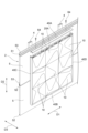
図1は、一実施形態に係る装飾構造を示す斜視図である。図2は、図1に示される装飾構造の支持部材及び下地材を示す斜視図である。図1に示される装飾構造1は、建物を装飾するために用いられる。本実施形態では、装飾構造1は、外壁2の上に施工される。外壁2の例としては、金属サイディングパネルによって構成される外壁、RC(Reinforced Concrete)造の外壁、窯業系外装材によって構成される外壁、及びALC(Autoclaved Lightweight Concrete)造の外壁が挙げられる。
FIG. 1 is a perspective view showing a decorative structure according to one embodiment. FIG. 2 is a perspective view showing the support member and base material of the decorative structure shown in FIG. 1. The
図1及び図2に示される例では、外壁2は、複数のサイディングパネル5が横張りされることによって構成されている。サイディングパネル5は、長尺の金属サイディングである。サイディングパネル5は、雄端部51と、雌端部52と、固定部53と、を備えている。雄端部51は、サイディングパネル5の短手方向における一端に設けられ、サイディングパネル5の長手方向に沿ってサイディングパネル5の全長にわたって延びている。雌端部52は、サイディングパネル5の短手方向における他端に設けられ、サイディングパネル5の長手方向に沿ってサイディングパネル5の全長にわたって延びている。雄端部51と雌端部52とは互いに嵌合可能に構成されている。具体的には、雄端部51は、短手方向に突出する凸形状を有している。雌端部52は、短手方向に窪む凹形状を有している。
In the example shown in FIGS. 1 and 2, the
固定部53は、サイディングパネル5を胴縁4に固定するための部分である。固定部53は、サイディングパネル5の短手方向における一端において、雄端部51よりも裏面側に設けられ、サイディングパネル5の長手方向に沿ってサイディングパネル5の全長にわたって延びている。固定部53に釘等の固定部材54(図13参照)が打ち込まれることによって、サイディングパネル5は胴縁4に固定される。サイディングパネル5は、雌端部52では胴縁4に固定されていない。このため、地震等によって外壁2に外力が加わったとしても、外力に応じて外壁2が変形する。つまり、地震等に起因する外力に対する追従性が得られる。
The fixing
図1及び図2に示される例では、各サイディングパネル5は、横方向D1に延在するように配置されている。複数のサイディングパネル5は、縦方向D2に配列されている。つまり、サイディングパネル5は、縦方向D2に延びる胴縁4に、横張りされている。具体的には、各サイディングパネル5は、雄端部51及び固定部53が上に位置し、雌端部52が下に位置するように、配置されている。上方に位置するサイディングパネル5の雌端部52と下方に位置するサイディングパネル5の雄端部51とが互いに嵌め合わされることによって、縦方向D2に互いに隣り合う2つのサイディングパネル5が連結されている。
In the example shown in FIGS. 1 and 2, each
図1及び図2に示されるように、装飾構造1は、複数のパネル材10と、複数の支持部材20と、複数の下地材30と、複数の廻縁40と、を備えている。本実施形態では、装飾構造1は、9つのパネル材10と、5つの支持部材20と、4つの下地材30と、4つの廻縁40と、を備えている。
As shown in FIGS. 1 and 2, the
パネル材10は、装飾用の部材である。各パネル材10は、複数の下地材30のうちの縦方向D2に互いに隣り合う2つの下地材30に取り付けられる。パネル材10は、4つの向きに施工可能に構成されている。具体的には、パネル材10は、後述の本体部11の表面11aを除いて、本体部11の中心軸CXを軸として、90度、180度、270度、及び360度で回転対称である。したがって、パネル材10は、本体部11の中心軸CXを軸として、90度、180度、270度、及び360度のいずれかの角度だけ回転させた向きで取り付けられる。パネル材10の材質は、例えば、アルミニウム及びチタン等の金属、並びに、プラスチック及び塩化ビニル等の樹脂である。パネル材10は、例えば、1枚の金属板に打ち抜き加工を施し、さらに折り曲げ加工を施すことによって作製される。
The
図3及び図4をさらに参照して、パネル材10を詳細に説明する。図3は、図1に示されるパネル材を示す斜視図である。図4は、図3に示されるパネル材の脚部を示す拡大図である。図3に示されるように、パネル材10は、本体部11と、4つの脚部12と、を備えている。
With further reference to FIGS. 3 and 4, the
本体部11は、平面視で正方形の形状を成す板状の部分である。本体部11は、外部に露出する表面11aを有している。表面11aは、装飾が施された面である。表面11aは、中心軸CXに対して非対称な形状の装飾を有している。図3に示される例では、表面11aの装飾は、外部に向かって隆起した形状を有している。本体部11は、平面視で正方形の形状を成す外縁部11bを有している。
The
4つの脚部12は、パネル材10を下地材30に取り付けるための板状の部分である。4つの脚部12は、本体部11の外縁部11bの4辺に沿ってそれぞれ設けられるとともに、外縁部11bから本体部11(表面11a)と交差する方向に突出している。各脚部12は、外縁部11bに沿って延在している。4つの脚部12は、互いに同一の形状を有している。なお、4つの脚部12のうちの1つの脚部12Aのみには、刻印Mが付されている。つまり、脚部12Aは、刻印Mを除いて他の脚部12と同一である。
The four
図4に示されるように、各脚部12には、貫通孔12a,12bと、挿通孔12c,12dと、貫通孔12eと、窪み12fと、が設けられている。
As shown in FIG. 4, each
貫通孔12a,12bは、脚部12の長手方向における両端部に設けられる。脚部12の長手方向における中心線Lcを対称軸として、貫通孔12aと貫通孔12bとは互いに線対称である。貫通孔12a,12bは、最上段のパネル材10を最上段の下地材30(下地材30A)に固定するために用いられる。貫通孔12a,12bは、ビス等の固定部材65(図20参照)の軸部が挿通可能な形状を有している。本実施形態では、貫通孔12a,12bは、丸孔である。
The through
挿通孔12cは、脚部12の長手方向において、貫通孔12aよりも中心線Lcに近い位置に設けられる。挿通孔12dは、脚部12の長手方向において貫通孔12bよりも中心線Lcに近い位置に設けられる。中心線Lcを対称軸として、挿通孔12cと挿通孔12dとは互いに線対称である。挿通孔12c,12dは、脚部12の長手方向に延びる長孔であって、下地材30の突起部34(図7参照)を挿通可能な形状を有している。挿通孔12c,12dは、突起部34を挿通しやすくするために突起部34の外形よりもわずかに大きい。挿通孔12c,12dの長手方向の中央付近には、突起部34のがたつきを軽減するために、狭窄部12g,12hがそれぞれ設けられている。挿通孔12c,12dの長手方向の両端には、R角が形成されている。挿通孔12c,12dは、パネル材10が最上段以外の下地材30に取り付けられる際に、下地材30の突起部34に挿通される。
The
貫通孔12eは、脚部12の長手方向において、挿通孔12dよりも中心線Lcに近い位置に設けられる。貫通孔12eは、固定部材65(図19参照)の軸部が挿通可能な形状を有している。本実施形態では、貫通孔12eは、脚部12の長手方向に延びる長孔である。貫通孔12eは、最上段以外のパネル材10を下地材30に固定するために用いられる。窪み12fは、脚部12の長手方向において、挿通孔12cよりも中心線Lcに近い位置に設けられる。貫通孔12eと窪み12fとは、中心線Lcを対称軸として、互いに線対称の位置に設けられている。窪み12fは、当該窪み12fが設けられたパネル材10の1つ下の段のパネル材10を下地材30に固定する固定部材65の頭部と脚部12との干渉を回避するために用いられる。つまり、窪み12fには、固定部材65の頭部が挿入される。
The through
図4には、脚部12Aが示されているので、刻印Mがさらに設けられている。刻印Mは、パネル材10の向きの識別性を向上させるために用いられる。
Since the
支持部材20は、下地材30を支持する長尺の部材である。支持部材20の形成材料は、例えば、アルミニウムである。支持部材20は、例えば、押出成形によって作製される。支持部材20は、装飾構造1を取り付ける位置を規定する。
The
図5、図6の(a)、及び図6(b)をさらに参照して、支持部材20を詳細に説明する。図5は、図2に示される支持部材を示す斜視図である。図6の(a)は、図5のVIa-VIa線に沿った断面図である。図6の(b)は、図5のVIb-VIb線に沿った断面図である。図5、図6の(a)、及び図6(b)に示されるように、支持部材20は、上板21と、側板22,23と、底板24と、突出片25と、を備えている。
The
上板21は、下地材30が載置される板状の部分である。上板21は、支持部材20の長手方向に沿って支持部材20の全長にわたって設けられている。上板21は、下地材30を載置するための載置面21aを有する。側板22,23は、上板21を支持する板状の部分である。側板22,23は、支持部材20の長手方向に沿って支持部材20の全長にわたって設けられている。側板22,23は、上板21を挟んで互いに向かい合うように設けられ、上板21と交差する方向に延びている。側板22の一端は、上板21の短手方向における一端に連なっている。側板23の一端は、上板21の短手方向における他端に連なっている。上板21、側板22、及び側板23は、下地材30を載置するための載置台を構成している。支持部材20の長手方向と交差する断面において、載置台は、U字状の断面形状を有している。
The
底板24は、支持部材20を外壁2に固定するための部分である。底板24は、支持部材20の長手方向に沿って支持部材20の全長にわたって設けられている。底板24の一端は、側板22の他端に連なっている。底板24は、側板22の他端から上板21と離れる方向に、上板21と略平行に延びている。底板24には、ビス等の固定部材61,62(図12参照)を位置決めするための溝24aが設けられている。溝24aは、底板24の長手方向に沿って延びており、底板24の全長にわたって設けられている。底板24の溝24aに固定部材61,62の先端が合わせられ、固定部材61,62が打ち込まれることによって、支持部材20は外壁2に固定される。
The
突出片25は、側板23の一端に連なっており、上板21の載置面21aから突出している。突出片25は、支持部材20の長手方向に沿って支持部材20の全長にわたって設けられ、支持部材20の長手方向において一部欠落している。つまり、突出片25には、いくつかの欠落部25aが設けられている。欠落部25aは、下地材30を嵌合可能な形状を有する。欠落部25aの長手方向における長さは、後述するベース31(図7参照)の短手方向における長さと略同じである。
The protruding
図2に示される例では、5つの支持部材20が配置されている。これらを区別する場合には、上の支持部材20、下の支持部材20、左の支持部材20、右の支持部材20、真ん中の支持部材20をそれぞれ支持部材20A(第2支持部材)、支持部材20B(第1支持部材)、支持部材20C(第3支持部材)、支持部材20D(第3支持部材)、及び支持部材20E(第3支持部材)と称することとする(図12等参照)。
In the example shown in FIG. 2, five
支持部材20A~20Dが装飾構造1の外周に沿って、矩形状を成すように配置されている。支持部材20A,20Bは、横方向D1に延在するとともに、互いに並行するように配置されている。支持部材20C,20Dは、縦方向D2に延在するとともに、互いに並行するように配置されている。支持部材20A~20Dのそれぞれは、載置面21aが外壁2と反対側を向くとともに、底板24が内側に位置するように配置される。支持部材20Eは、支持部材20C,20Dの間に配置され、胴縁4に沿って延在している。つまり、支持部材20C~20Eは、縦方向D2に延在するとともに、横方向D1に互いに並行するように設けられている。
下地材30は、パネル材10を取り付けるための部材である。下地材30は、長尺状の部材である。下地材30の形成材料は、例えば、アルミニウムである。下地材30は、例えば、押出成形によって作製される。
The
図7、及び図8をさらに参照して、下地材30を詳細に説明する。図7は、図2に示される下地材を示す斜視図である。図8は、図7のVIII-VIII線に沿った断面図である。図7及び図8に示されるように、下地材30は、ベース31と、取付板32と、連結部33と、突起部34と、突出部35と、凸部36と、を備えている。
With further reference to FIGS. 7 and 8, the
ベース31は、支持部材20の上板21に載置され、支持部材20に固定される板状の部分である。ベース31は、下地材30の長手方向に沿って下地材30の全長にわたって設けられている。ベース31は、面31aと、面31aとは反対側の面31bと、を有する。面31bは、支持部材20の載置面21aに接触している。ベース31の面31aには、ビス等の固定部材63(図14参照)を位置決めするための2本の溝31cが設けられている。溝31cは、ベース31の長手方向に沿って延びており、ベース31の全長にわたって設けられている。ベース31には、取付板32とは反対側の端面に面31aから面31bまで延びる溝31dが設けられている。ベース31の長手方向における一端と当該一端に最も近い溝31dとの距離は、上板21の短手方向における長さ(幅)と略等しい。
The
取付板32は、下地材30にパネル材10を取り付けるための板状の部分である。取付板32は、下地材30の長手方向に沿って下地材30の全長にわたって設けられている。取付板32は、ベース31に対して直角を成すように設けられている。取付板32は、面32aと、面32aと反対側の面32bと、を有する。面32aは、ベース31側を向く面である。
The
面32aには、複数の突起部34が設けられている。各突起部34は、面32aの法線方向に突出しており、下地材30の長手方向に延在している。突起部34は、挿通孔12c,12dに挿通しやすくするために、先端に向かうにつれて細くなるテーパー形状を有している。つまり、下地材30の長手方向と交差する断面において、突起部34は、五角形の断面形状を有する。複数の突起部34は、下地材30の長手方向に一定の間隔で設けられている。互いに隣り合う2つの突起部34の間隔は、脚部12の挿通孔12cと挿通孔12dとの間隔と略同じである。突起部34の根元部分には、くびれ34aが設けられている。突起部34の突出方向におけるくびれ34aの長さは、1つの脚部12の厚みと同程度である。
A plurality of
取付板32には、取付板32を貫通する貫通孔32c,32d,32eが設けられている。貫通孔32c,32d,32eは、面32aから面32bに向かって取付板32を貫通している。貫通孔32c,32dは、最上段のパネル材10を最上段の下地材30(下地材30A)に固定するために用いられる。貫通孔32c,32dは、固定部材65(図20参照)の軸部が挿通可能な形状を有している。貫通孔32c,32dは、下地材30の長手方向に延びる長孔である。貫通孔32c,32dは、下地材30の長手方向において、突起部34を挟むように設けられている。
The mounting
貫通孔32eは、最上段以外のパネル材10を下地材30に固定するために用いられる。貫通孔32eは、固定部材65(図19参照)の軸部が挿通可能な形状を有している。貫通孔32eは、丸孔である。貫通孔32eは、下地材30の長手方向において、貫通孔32dと隣り合うように設けられている。下地材30の長手方向において、貫通孔32c、突起部34、貫通孔32d、及び貫通孔32eがその順番に配列されている。取付板32には、貫通孔32c、突起部34、貫通孔32d、及び貫通孔32eによって構成される組が一定の間隔で設けられている。
The through
連結部33は、ベース31と取付板32とを連結する部分である。連結部33は、下地材30の長手方向に沿って下地材30の全長にわたって設けられている。連結部33は、ベース31と取付板32とが直角を成すようにベース31と取付板32とを連結している。連結部33の一端はベース31の面31aに接続され、連結部33の他端は取付板32の面32aに接続される。面31bと連結部33との間に段部が形成されている。
The connecting
突出部35及び凸部36は、下地材30を支持部材20に係止するための部分である。突出部35は、連結部33の段部を形成する面に設けられ、下地材30の長手方向の全長にわたって延在している。突出部35は、ベース31の面31bと同一平面まで突出している。突出部35とベース31と連結部33とによって溝37が画成される。凸部36は、面32bに設けられ、下地材30の長手方向の全長にわたって延在している。凸部36と突出部35とは直角を成し、凸部36と突出部35とによって凹部38が画成される。
The protruding
図2に示される例では、4つの下地材30が、横方向D1に延在するとともに、縦方向D2に所定の間隔で互いに並行するように設けられている。これらを区別する場合には、縦方向D2における一端(上端)に位置する下地材30を下地材30A(第2下地材)と称し、縦方向D2における他端(下端)に位置する下地材30を下地材30B(第1下地材)と称し、下地材30Aと下地材30Bとの間に位置する下地材30を上から順に下地材30C(第3下地材)、及び下地材30D(第3下地材)と称することとする(図14等参照)。
In the example shown in FIG. 2, four
下地材30Aは、面31bが載置面21aと向かい合うとともに突起部34が下方に向けて突出するように配置され、それ以外の下地材30B,30C,30Dは、面31bが載置面21aと向かい合うとともに突起部34が上方に向けて突出するように配置される。下地材30Aは、方向D3から見て支持部材20Aと重なっている。下地材30Bは、方向D3から見て支持部材20Bと重なっている。下地材30C,30Dは、支持部材20C,20E,20Dと交差するように設けられている。支持部材20と下地材30との係止構造については、装飾構造1の施工方法の説明において詳述する。
The
廻縁40は、小口を隠すための部材である。廻縁40の形成材料は、例えば、アルミニウム、及びチタン等の金属である。廻縁40は、例えば、押出成形によって作製される。廻縁40によって、パネル材10の脚部12、支持部材20、及び下地材30が覆い隠される。
The
図9をさらに参照して廻縁40を詳細に説明する。図9は、図1に示される廻縁を示す斜視図である。図9に示されるように、廻縁40は、上板41と、側板42,43と、底板44と、係止片45と、を備えている。
With further reference to FIG. 9, the
上板41は、小口を覆う板状の部分である。上板41は、廻縁40の長手方向に沿って廻縁40の全長にわたって設けられている。側板42,43は、上板41を支持する板状の部分である。側板42,43は、廻縁40の長手方向に沿って廻縁40の全長にわたって設けられている。側板42,43は、上板41を挟んで互いに向かい合うように設けられ、上板41と交差する方向に延びている。側板42の一端は、上板41の短手方向における一端に連なっている。側板43の一端は、上板41の短手方向における他端に連なっている。
The
底板44は、廻縁40を支持部材20に固定するための部分である。底板44は、廻縁40の長手方向に沿って廻縁40の全長にわたって設けられている。底板44の一端は、側板42の他端に連なっており、底板44は、側板42の他端から上板41と離れる方向に、上板41と略平行に延びている。底板44にビス等の固定部材64(図18及び図21参照)が打ち込まれることによって、廻縁40は支持部材20の側板23に固定される。係止片45は、側板23の他端に連なっており、側板23の他端から内側に向かって突出している。係止片45は、廻縁40の長手方向に沿って廻縁40の全長にわたって設けられている。係止片45は、パネル材10の脚部12に当接する。
The
図1に示される例では、4つの廻縁40が、装飾構造1の上端、下端、及び左右両端にそれぞれ位置し、装飾構造1の枠を成している。これらを区別する場合には、上の廻縁40、下の廻縁40、左の廻縁40、及び右の廻縁40をそれぞれ廻縁40A、廻縁40B、廻縁40C、及び廻縁40Dと称することとする(図18及び図21等参照)。廻縁40A~40Dは、底板44が支持部材20A~20Dの側板23にそれぞれ載置され、係止片45が脚部12に当接するように配置されている。
In the example shown in FIG. 1, four
なお、固定部材61~65の材質は、例えば、ステンレスである。固定部材61~65には、高耐食表面処理加工が施されていてもよい。雨水の浸入を防止するために、固定部材61~65として、パッキン付きの固定部材が用いられてもよい。パッキンは、例えば、EPDM(エチレンプロピレンジエンゴム)で構成されている。
Note that the material of the fixing
次に、図10~図21を参照して、装飾構造1の施工方法を説明する。図10は、図1に示される装飾構造の施工方法を示す工程図である。図11は、図10に示される墨出し工程を説明するための図である。図12は、図10に示される支持部材の取り付け工程を説明するための図である。図13は、図12のXIII-XIII線に沿った断面図である。図14は、図10に示される下地材の取り付け工程を説明するための図である。図15は、図14のXV-XV線に沿った断面図である。図16は、図14のXVI-XVI線に沿った断面図である。図17は、図14の一部を拡大して示す図である。図18は、図10に示される廻縁の取り付け工程を説明するための図である。図19は、図10に示されるパネル材の取り付け工程を説明するための図である。図20は、図10に示されるパネル材の取り付け工程を説明するための図である。図21は、図10に示される上廻縁の取り付け工程を説明するための図である。
Next, a method for constructing the
図10に示されるように、まず墨出し工程S1が行われる。墨出し工程S1では、外壁2において、装飾構造1を取り付ける位置に破線L1が描かれる。装飾構造1を取り付ける位置は、例えば、装飾構造1の外周である。装飾構造1の外周は、横方向D1及び縦方向D2に施工されるパネル材10の数に応じて決定される。墨出し工程S1では、外壁2において、さらに胴縁4の位置を示す破線L2が描かれる。
As shown in FIG. 10, first, a marking step S1 is performed. In the marking step S1, a broken line L1 is drawn on the
続いて、支持部材20の取り付け工程S2が行われる。支持部材20の取り付け工程S2では、支持部材20A~20Dが破線L1に沿って外壁2上に配置される。具体的には、支持部材20A~20Dは、底板24が破線L1で囲まれた枠の中心を向き、突出片25が外側(外壁2とは反対側)に突出するとともに、側板23の他端が破線L1に沿うように、配置される。さらに、支持部材20Eが破線L2に沿って外壁2上に配置される。具体的には、支持部材20Eは、突出片25が外側(外壁2とは反対側)に突出するとともに、底板24の先端が破線L2に沿うように配置される。
Subsequently, a step S2 of attaching the
そして、各支持部材20が固定部材61及び固定部材62によって外壁2に固定される。各支持部材20は、例えば長手方向に沿った3か所において固定部材61又は固定部材62によって固定される。胴縁4上に位置する底板24には固定部材61が用いられ、胴縁4上に位置しない24には固定部材61よりも短い固定部材62が用いられる。なお、固定部材61,62の先端が溝24aに合わせられた状態で、固定部材61,62が打ち込まれる。これにより、固定部材61は、底板24、サイディングパネル5、及び胴縁4を貫通し、固定部材62は、底板24を貫通してサイディングパネル5に突き刺さる。
Then, each
支持部材20A,20Bは、横方向D1に互いに隣り合う2つの胴縁4上に跨って配置される。支持部材20A,20Bは、2つの胴縁4上において固定部材61によって固定され、右端において固定部材62によって固定される。支持部材20C~20Eは、縦方向D2に互いに隣り合う2つのサイディングパネル5に跨って配置される。支持部材20C,20Eは、縦方向D2における両端と中央付近とにおいて、固定部材61によって固定される。支持部材20Dは、縦方向D2における両端と中央付近とにおいて、固定部材62によって固定される。このとき、支持部材20C~20Eの中央では、外壁2の追従性を阻害しないように、サイディングパネル5の雄端部51付近に固定部材61,62が打ち込まれる。
The
続いて、下地材30の取り付け工程S3が行われる。下地材30の取り付け工程S3では、それぞれが横方向D1に延在するとともに、縦方向D2に所定の間隔で互いに並行に配列されるように複数の下地材30が取り付けられる。具体的には、下地材30Aは支持部材20Aに取り付けられる。より具体的に説明すると、図15に示されるように、突起部34が下方に向けて突出するように、下地材30Aのベース31が支持部材20Aの上板21に重ね合わせられて載置される。このとき、下地材30Aの突出部35が支持部材20Aの突出片25に下方から押し当てられ、支持部材20Aの突出片25が下地材30Aの凹部38に嵌め合わされる。そして、下地材30Aは、例えば長手方向に沿った3か所において固定部材63によって支持部材20Aの上板21に固定される。
Subsequently, a step S3 of attaching the
下地材30Bは、支持部材20Bに取り付けられる。より具体的に説明すると、図16に示されるように、突起部34が上方に向けて突出するように、下地材30Bのベース31が支持部材20Bの上板21上に載置される。このとき、下地材30Bの溝37に支持部材20Bの突出片25が挿入されつつ、支持部材20Bの上板21に下地材30Bのベース31が重ね合わせられて載置される。そして、下地材30Bは、例えば長手方向に沿った3か所において固定部材63によって支持部材20Bの上板21に固定される。
下地材30C,30Dは、支持部材20C~20Eに跨って取り付けられる。より具体的に説明すると、図17に示されるように、突起部34が上方に向けて突出するように、下地材30C,30Dのベース31が支持部材20C~20Eの上板21に跨って載置される。このとき、支持部材20C~20Eの欠落部25aに下地材30C,30Dのベース31及び突出部35が嵌め込まれるとともに、下地材30C,30Dの溝31dが支持部材20Cの上板21と側板22とによって形成される角と重なるように下地材30C,30Dの横方向D1における位置が合わせられる。そして、下地材30C,30Dは、支持部材20C~20Eの上板21上において、固定部材63によって各支持部材20の上板21に固定される。
The
なお、固定部材63の先端が溝31cに合わせられた状態で、固定部材63が打ち込まれる。これにより、固定部材63は、ベース31及び上板21を貫通する。
Note that the fixing
続いて、廻縁40(廻縁40B~40D)の取り付け工程S4が行われる。廻縁40の取り付け工程S4では、廻縁40B~40Dが取り付けられる。具体的には、底板44が支持部材20B,20C,20Dの側板23に重ね合わせられ、廻縁40B~40Dの係止片45がU字状を成すように、廻縁40B~40Dがそれぞれ配置される。そして、廻縁40B~40Dは、各廻縁40の長手方向における両端近傍において、固定部材64によって支持部材20B,20C,20Dの側板23にそれぞれ固定される。固定部材64は、底板44及び側板23を貫通する。
Subsequently, a step S4 for attaching the circumferential edges 40 (
続いて、パネル材10の取り付け工程S5が行われる。パネル材10の取り付け工程S5では、複数の下地材30のうちの縦方向D2において互いに隣り合う2つの下地材30に各パネル材10が取り付けられる。各パネル材10は、4つの脚部12のうちの少なくともいずれか1つの脚部12に設けられた挿通孔12c,12dに、下地材30の突起部34を挿通させることによって、下地材30に取り付けられる。例えば、作業指示書において、パネル材10の施工向きが刻印Mの方向(上下左右)によって示される。作業者は、例えば、刻印Mが下を示す場合には、脚部12Aが下に位置するようにパネル材10の施工向きを合わせる。
Subsequently, a step S5 of attaching the
具体的に説明すると、図19に示されるように、まず左下のパネル材10が、下地材30D及び下地材30Bに取り付けられる。具体的には、4つの脚部12のうちの下に位置する脚部12の挿通孔12c,12dに下地材30Bの左端から1番目及び2番目の突起部34を挿通させるとともに、4つの脚部12のうちの上に位置する脚部12の挿通孔12c,12dに下地材30Dの左端から1番目及び2番目の突起部34を挿通させる。これにより、上に位置する脚部12の貫通孔12eと下地材30Dの左端から一番目の貫通孔32eとが縦方向D2において重なり合うので、固定部材65が貫通孔12eから挿通され、貫通孔32eに螺合される。
Specifically, as shown in FIG. 19, the lower
ここで、下地材30Bの取付板32の面32aと下地材30Dの取付板32の面32aとの縦方向D2における距離は、パネル材10の互いに向かい合う脚部12の距離よりも1つの脚部12の厚さ分程度大きい。この構成では、上に位置する脚部12は、下地材30Dの突起部34のくびれ34aに嵌り込む。くびれ34aでは、突起部34と挿通孔12c,12dの周縁との間にわずかにスペースが生じるが、固定部材65によって脚部12が固定される。一方、下に位置する脚部12は、下地材30Bの突起部34のくびれ34aには嵌り込まず、くびれ34aの上方に位置する。この位置では、突起部34と挿通孔12c,12dの周縁との間にほとんどスペースが生じておらず、さらに狭窄部12g,12hによって脚部12が動くことが抑制される。したがって、下に位置する脚部12が、固定部材によって下地材30Bに固定されなくても、その位置がずれる可能性が低減される。
Here, the distance in the vertical direction D2 between the
挿通孔12c,12dの横方向D1における長さは突起部34の横方向D1における長さよりも大きく、貫通孔12eは横方向D1に延びる長孔である。したがって、上に位置する脚部12が下地材30Bに固定される前に、パネル材10の横方向D1における位置が微調整され得る。ここでは、廻縁40C(の係止片45)にパネル材10の左端を突き当てることによって、パネル材10が位置決めされる。続いて、取り付けられたパネル材10の右側にパネル材10が同様の手順によって順に取り付けられる。
The lengths of the insertion holes 12c and 12d in the lateral direction D1 are larger than the length of the
さらに、下から2段目のパネル材10が下地材30C及び下地材30Dに取り付けられる。下地材30C及び下地材30Dにも同様に、左端から順にパネル材10が取り付けられる。具体的には、4つの脚部12のうちの下に位置する脚部12の挿通孔12c,12dに下地材30Dの左端から1番目及び2番目の突起部34を挿通させるとともに、4つの脚部12のうちの上に位置する脚部12の挿通孔12c,12dに下地材30Cの左端から1番目及び2番目の突起部34を挿通させる。このとき、下段のパネル材10を固定するために用いられた固定部材65の頭部が、下に位置する脚部12の窪み12fに挿入される。これにより、上に位置する脚部12の貫通孔12eと下地材30Cの左端から1番目の貫通孔32eとが縦方向D2において重なり合うので、固定部材65が貫通孔12eから挿通され、貫通孔32eに螺合される。
Further, the
ここで、下地材30Cの取付板32の面32aと下地材30Dの取付板32の面32aとの縦方向D2における距離は、パネル材10の互いに向かい合う脚部12の距離よりも1つの脚部12の厚さ分程度大きい。この構成では、上に位置する脚部12は、下地材30Cの突起部34のくびれ34aに嵌り込む。一方、下地材30Dの突起部34のくびれ34aにはすでに下段のパネル材10の脚部12が嵌り込んでいるので、下に位置する脚部12は、下地材30Dの突起部34のくびれ34aには嵌り込まず、くびれ34aの上方に位置する。この位置では、突起部34と挿通孔12c,12dの周縁との間にほとんどスペースが生じておらず、さらに狭窄部12g,12hによって脚部12が動くことが抑制される。したがって、下に位置する脚部12が、固定部材によって下地材30Dに固定されなくても、その位置がずれる可能性が低減される。
Here, the distance in the vertical direction D2 between the
そして、廻縁40C(の係止片45)にパネル材10の左端を突き当てることによって、パネル材10が位置決めされる。続いて、取り付けられたパネル材10の右側にパネル材10が同様の手順によって順に取り付けられる。
Then, the
さらに、最上段のパネル材10が下地材30A及び下地材30Cに取り付けられる。下地材30A及び下地材30Cにも、左端から順にパネル材10が取り付けられる。具体的には、4つの脚部12のうちの下に位置する脚部12の挿通孔12c,12dに下地材30Cの左端から1番目及び2番目の突起部34を挿通させるとともに、4つの脚部12のうちの上に位置する脚部12を下地材30Aの取付板32の面32bに載置する。このとき、下段のパネル材10を固定するために用いられた固定部材65の頭部が、下に位置する脚部12の窪み12fに挿入される。これにより、上に位置する脚部12の貫通孔12aと下地材30Aの左端から1番目の貫通孔32dとが縦方向D2において重なり合い、上に位置する脚部12の貫通孔12bと下地材30Aの左から2番目の貫通孔32cとが縦方向D2において重なり合う。したがって、固定部材65が貫通孔12a,12bからそれぞれ挿通され、貫通孔32d,32cに螺合される。
Furthermore, the
ここで、下地材30Aの取付板32の面32bと下地材30Cの取付板32の面32aとの縦方向D2における距離は、パネル材10の互いに向かい合う脚部12の距離よりも1つの脚部12の厚さ分程度大きい。下地材30Cの突起部34のくびれ34aにはすでに下段のパネル材10の脚部12が嵌り込んでいるので、下に位置する脚部12は、下地材30Cの突起部34のくびれ34aには嵌り込まず、くびれ34aの上方に位置する。この位置では、突起部34と挿通孔12c,12dの周縁との間にほとんどスペースが生じておらず、さらに狭窄部12g,12hによって脚部12が動くことが抑制される。したがって、下に位置する脚部12が、固定部材によって下地材30Cに固定されなくても、その位置がずれる可能性が低減される。
Here, the distance in the vertical direction D2 between the
貫通孔32c,32dは横方向D1に延びる長孔である。したがって、上に位置する脚部12が下地材30Aに固定される前に、パネル材10の横方向D1における位置が微調整され得る。ここでは、廻縁40C(の係止片45)にパネル材10の左端を突き当てることによって、パネル材10が位置決めされる。続いて、取り付けられたパネル材10の右側にパネル材10が同様の手順によって順に取り付けられる。
The through
なお、縦方向D2において隣り合うパネル材10の横方向D1における位置を揃えるように、各パネル材10の横方向D1における位置が微調整される。
Note that the position of each
続いて、廻縁40Aの取り付け工程S6が行われる。廻縁40Aの取り付け工程S6では、廻縁40の取り付け工程S4と同様に、底板44が支持部材20Aの側板23に重ね合わせられ、係止片45が最上段のパネル材10の脚部12に当接するように、廻縁40Aが配置される。そして、廻縁40Aは、廻縁40Aの長手方向における両端近傍において、固定部材64によって支持部材20Aの側板23に固定される。
Subsequently, a step S6 for attaching the
以上により、装飾構造1が外壁2上に施工される。
Through the above steps, the
以上説明した装飾構造1、パネル材10、及び装飾構造1の施工方法では、パネル材10の4つの脚部12のうちの少なくともいずれか1つの脚部12に設けられた挿通孔12c,12dに、縦方向D2に互いに隣り合う2つの下地材30のうちの一方の下地材30の突起部34を挿通させることによって、パネル材10が取り付けられる。4つの脚部12は、平面視で正方形の形状を成す外縁部11bの4辺に沿って設けられるとともに、外縁部11bから本体部11と交差(直交)する方向に延びており、互いに同一形状を有している。つまり、パネル材10は、表面11aを除いて、本体部11の中心軸CXを軸として、90度、180度、270度、及び360度で回転対称である。言い換えると、パネル材10の4つの脚部12は、本体部11の中心軸CXを軸として、90度、180度、270度、及び360度で回転対称である。したがって、本体部11の中心軸CXを軸として、90度、180度、270度、及び360度のいずれの角度だけ回転させても、パネル材10を下地材30に取り付けることができる。その結果、パネル材10の施工向きを変更することが可能となる。
In the
パネル材10の表面11aは、中心軸CXに対して非対称な形状の装飾を有している。このため、各パネル材10が、パネル材10ごとに90度、180度、270度、及び360度のいずれかの回転角度で任意に取り付けられることによって、装飾構造1が様々な表情を生み出すことができる。したがって、装飾構造1のデザイン性を向上させることが可能となる。
The
複数の支持部材20のそれぞれは、当該支持部材20の延在方向に延びるとともに方向D3に突出する突出片25を備えている。各下地材30は、支持部材20の突出片25によって位置決めされるので、下地材30の取り付け作業を簡易化することができるとともに、下地材30の施工精度を向上させることができる。
Each of the plurality of
具体的に説明すると、複数の支持部材20は、下地材30Aを支持する支持部材20A、下地材30Bを支持する支持部材20B、及び下地材30C,30Dを支持する支持部材20C~20Eを含む。下地材30Aの突出部35を支持部材20Aの突出片25に縦方向D2において当接させた状態で、下地材30Aが支持部材20Aに取り付けられる。この当接によって下地材30Aの縦方向D2における位置が定まるので、作業者が下地材30Aの縦方向D2における位置を調整する作業を省略することができる。したがって、下地材30Aの取り付け作業を簡易化することができる。
Specifically, the plurality of
下地材30Bに設けられた溝37に支持部材20Bの突出片25を嵌め合わせた状態で、下地材30Bが支持部材20Bに取り付けられる。この嵌合構造によって下地材30Bの縦方向D2における位置が定まるので、作業者が下地材30Bの縦方向D2における位置を調整する作業を省略することができる。したがって、下地材30Bの取り付け作業を簡易化することができる。
The
下地材30C,30Dを支持部材20C,20D,20Eの突出片25に設けられた欠落部25aに嵌め合わせた状態で、下地材30C,30Dが支持部材20C,20D,20Eに取り付けられる。この嵌合構造によって下地材30C,30Dの縦方向D2における位置が定まるので、作業者が下地材30C,30Dの縦方向D2における位置を調整する作業を省略することができる。したがって、下地材30C,30Dの取り付け作業を簡易化することができる。
The
このように、支持部材20に下地材30をシステマチックに取り付けることができる。
In this way, the
パネル材10の脚部12Aには、刻印Mが付されている。このため、作業指示書において、パネル材10の施工向きを刻印Mの方向(上下左右)によって示すことができる。したがって、作業者がパネル材10の施工向きを容易に判断することができるので、パネル材10の施工性を向上させることが可能となる。
A stamp M is attached to the
支持部材20A~20Eが外壁2上に取り付けられ、下地材30A~30Dが支持部材20A~20E上に取り付けられる。さらに、複数のパネル材10が下地材30A~30Dに取り付けられる。したがって、外壁2の形状に影響されることなく、パネル材10を施工することが可能となる。
支持部材20C~20Eは、サイディングパネル5の延在方向(横方向D1)と直交する縦方向D2に配置され、縦方向D2に互いに隣り合う2つのサイディングパネル5に跨って取り付けられる。この構成によって、上側のサイディングパネル5の雌端部52と下側のサイディングパネル5の雄端部51との嵌合が外れにくくなる。その結果、外壁2の耐風圧性能を向上させることが可能となる。
The
左端のパネル材10は、廻縁40C(の係止片45)にパネル材10の左端を突き当てることによって、位置決めされる。左端以外のパネル材10は、当該パネル材10の左側に位置するパネル材10の右端に、当該パネル材10の左端を突き当てることによって、位置決めされる。この構成により、横方向D1において互いに隣り合う2つのパネル材10間の隙間(目地)を小さくすることができる。
The left
下地材30C,30Dの突起部34は、下段のパネル材10の脚部12に設けられた挿通孔12c,12dと、上段のパネル材10の脚部12に設けられた挿通孔12c,12dと、に挿通され、縦方向D2において互いに隣り合う2つのパネル材10の脚部12が下地材30C,30Dに取り付けられる。この構成により、縦方向D2において互いに隣り合う2つのパネル材10間の隙間(目地)を小さくすることができる。
The
なお、本開示に係る装飾構造、パネル材、及び装飾構造の施工方法は上記実施形態に限定されない。 Note that the decorative structure, panel material, and method for constructing the decorative structure according to the present disclosure are not limited to the above embodiments.
上記実施形態では、装飾構造1が施工される外壁2は、複数のサイディングパネル5が横張りされることによって構成されているが、この構成に限られない。例えば、図22に示されるように、装飾構造1が施工される外壁2は、複数のサイディングパネル5が縦張りされることによって構成されてもよい。この場合、装飾構造1は、時計回りに90度回転されて設けられてもよい。装飾構造1は、外壁に限られず、内壁に施工されてもよい。
In the embodiment described above, the
表面11aの装飾の形状としては、任意の形状が採用され得る。例えば、図23に示されるように、表面11aの装飾の形状は、外縁部11bの互いに向かい合う1組の辺のうちの一方の辺から他方の辺に向けて傾斜する形状であってもよい。
Any shape may be adopted as the shape of the decoration on the
上記実施形態では、装飾構造1は、9つのパネル材10を備えているが、パネル材10の数は、所望の装飾構造1の大きさに応じて変更され得る。横方向D1におけるパネル材10の数に応じて、支持部材20A,20B、下地材30A~30D、及び廻縁40A,40Bの長さは調整される。縦方向D2におけるパネル材10の数に応じて、支持部材20C~20E、及び廻縁40C,40Dの長さ、並びに下地材30の数は調整される。
In the above embodiment, the
上記実施形態では、支持部材20A~20Eは、互いに同じ形状を有しているが、異なる形状を有してもよい。同様に、上記実施形態では、下地材30A~30Dは、互いに同じ形状を有しているが、異なる形状を有してもよい。例えば、下地材30Aは、支持部材20Aの突出片25と縦方向D2において当接する突出部35を備えていればよく、溝37は設けられていなくてもよい。下地材30Bには、支持部材20Bの突出片25に嵌り合う溝37が設けられていればよく、下地材30Bは、凸部36を備えていなくてもよい。下地材30C,30Dは、支持部材20C~20Eに設けられた欠落部25aに嵌り合う形状を有していればよく、溝37は設けられていなくてもよい。
In the above embodiment, the
上記実施形態では、廻縁40A~40Dは、互いに同じ形状を有しているが、異なる形状を有してもよい。
In the above embodiment, the
1…装飾構造、2…外壁、4…胴縁、5…サイディングパネル、10…パネル材、11…本体部、11a…表面、11b…外縁部、12…脚部、12a…貫通孔、12b…貫通孔、12c…挿通孔、12d…挿通孔、12e…貫通孔、20…支持部材、20A…支持部材(第2支持部材)、20B…支持部材(第1支持部材)、20C,20D,20E…支持部材(第3支持部材)、21…上板、21a…載置面、22…側板、23…側板、24…底板、24a…溝、25…突出片、25a…欠落部、30…下地材、30A…下地材(第2下地材)、30B…下地材(第1下地材)、30C,30D…下地材(第3下地材)、31…ベース、31a…面、31b…面、31c…溝、31d…溝、32…取付板、32a…面、32b…面、32c…貫通孔、32d…貫通孔、32e…貫通孔、33…連結部、34…突起部、34a…くびれ、35…突出部、36…凸部、37…溝、38…凹部、40,40A,40B,40C,40D…廻縁、41…上板、42…側板、43…側板、44…底板、45…係止片、51…雄端部、52…雌端部、53…固定部、54,61~65…固定部材、CX…中心軸、D1…横方向(第1方向)、D2…縦方向(第2方向)、D3…方向(第3方向)、L1…破線、L2…破線、Lc…中心線、M…刻印。
DESCRIPTION OF
Claims (5)
それぞれが前記複数の下地材のうちの前記第2方向に互いに隣り合う2つの下地材に取り付けられる複数のパネル材と、
前記複数の下地材を支持する長尺の複数の支持部材と、
を備え、
前記複数の下地材のそれぞれは、前記第2方向に突出する突起部を備え、
前記複数のパネル材のそれぞれは、平面視で正方形の形状を成す外縁部を有する本体部と、前記外縁部の4辺に沿ってそれぞれ設けられるとともに前記外縁部から前記本体部と交差する方向に延びる4つの脚部と、を備え、
前記4つの脚部は、互いに同一の形状を有し、
前記4つの脚部のそれぞれには、前記突起部を挿通可能な挿通孔が設けられており、
前記4つの脚部のうちの1つの脚部に設けられた前記挿通孔に、前記2つの下地材のうちの一方の下地材の前記突起部を挿通させることによって、前記パネル材が取り付けられており、
前記複数の支持部材のそれぞれは、当該支持部材の延在方向に延びるとともに前記第1方向及び前記第2方向と交差する第3方向に突出する突出片を備え、
前記複数の下地材は、前記突出片によって位置決めされる、装飾構造。 a plurality of base materials each extending in a first direction and provided in parallel with each other at predetermined intervals in a second direction intersecting the first direction;
a plurality of panel materials, each of which is attached to two base materials adjacent to each other in the second direction among the plurality of base materials;
a plurality of elongated support members that support the plurality of base materials;
Equipped with
Each of the plurality of base materials includes a protrusion protruding in the second direction,
Each of the plurality of panel materials includes a main body having an outer edge having a square shape in a plan view, and a main body provided along four sides of the outer edge, and extending from the outer edge in a direction intersecting the main body. comprising four extending legs;
The four legs have the same shape,
Each of the four legs is provided with an insertion hole through which the protrusion can be inserted,
The panel material is attached by inserting the protrusion of one of the two base materials into the insertion hole provided in one of the four leg parts. Ori,
Each of the plurality of support members includes a protrusion piece that extends in the extending direction of the support member and protrudes in a third direction that intersects the first direction and the second direction,
A decorative structure in which the plurality of base materials are positioned by the protruding pieces .
前記複数の支持部材は、前記第1下地材を支持する第1支持部材を含み、
前記第1支持部材は、前記第1方向に延在するとともに、前記第3方向から見て前記第1下地材と重なっており、
前記第1下地材には、前記第1支持部材の前記突出片に嵌り合う溝が設けられている、請求項1に記載の装飾構造。 The plurality of base materials include a first base material located at one end in the second direction of the plurality of base materials,
The plurality of support members include a first support member that supports the first base material,
The first support member extends in the first direction and overlaps the first base material when viewed from the third direction,
The decorative structure according to claim 1 , wherein the first base material is provided with a groove that fits into the protruding piece of the first support member.
前記複数の支持部材は、前記第2下地材を支持する第2支持部材をさらに含み、
前記第2支持部材は、前記第1方向に延在するとともに、前記第3方向から見て前記第2下地材と重なっており、
前記第2下地材は、前記第2支持部材の前記突出片と前記第2方向において当接する突出部をさらに備える、請求項2に記載の装飾構造。 The plurality of base materials further include a second base material located at the other end of the plurality of base materials in the second direction,
The plurality of support members further include a second support member that supports the second base material,
The second support member extends in the first direction and overlaps the second base material when viewed from the third direction,
The decorative structure according to claim 2 , wherein the second base material further includes a protrusion that abuts the protrusion piece of the second support member in the second direction.
前記複数の支持部材は、前記第3下地材を支持する複数の第3支持部材をさらに含み、
前記複数の第3支持部材は、前記第2方向に延在するとともに、前記第1方向に互いに並行に設けられ、
前記複数の第3支持部材の前記突出片には、前記第3下地材に嵌り合う欠落部が設けられている、請求項3に記載の装飾構造。 The plurality of base materials further include a third base material located between the first base material and the second base material in the second direction,
The plurality of support members further include a plurality of third support members that support the third base material,
The plurality of third support members extend in the second direction and are provided in parallel to each other in the first direction,
4. The decorative structure according to claim 3 , wherein the protruding pieces of the plurality of third support members are provided with missing portions that fit into the third base material.
それぞれが第1方向に延在するとともに、前記第1方向と交差する第2方向に所定の間隔で互いに並行に配列されるように、前記複数の支持部材に複数の下地材を取り付ける工程と、
前記複数の下地材のうちの前記第2方向に互いに隣り合う2つの下地材にパネル材を取り付ける工程と、を備え、
前記複数の下地材のそれぞれは、前記第2方向に突出する突起部を備え、
前記パネル材は、平面視で正方形の形状を成す外縁部を有する本体部と、前記外縁部の4辺に沿ってそれぞれ設けられるとともに前記外縁部から前記本体部と交差する方向に延びる4つの脚部と、を備え、
前記4つの脚部は、互いに同一の形状を有し、
前記4つの脚部のそれぞれには、前記突起部を挿通可能な挿通孔が設けられており、
前記パネル材を取り付ける工程では、前記4つの脚部のうちのいずれか1つの脚部に設けられた前記挿通孔に、前記2つの下地材のうちの一方の下地材の前記突起部を挿通させることによって、前記パネル材が取り付けられ、
前記複数の支持部材のそれぞれは、当該支持部材の延在方向に延びるとともに前記第1方向及び前記第2方向と交差する第3方向に突出する突出片を備え、
前記複数の下地材を取り付ける工程では、前記複数の下地材は、前記突出片によって位置決めされる、装飾構造の施工方法。 a step of attaching a plurality of long support members;
attaching a plurality of base materials to the plurality of support members so that each base material extends in a first direction and is arranged parallel to each other at predetermined intervals in a second direction intersecting the first direction;
attaching panel materials to two base materials adjacent to each other in the second direction among the plurality of base materials,
Each of the plurality of base materials includes a protrusion protruding in the second direction,
The panel material includes a main body portion having an outer edge portion having a square shape in plan view, and four legs provided along four sides of the outer edge portion and extending from the outer edge portion in a direction intersecting the main body portion. and,
The four legs have the same shape,
Each of the four legs is provided with an insertion hole through which the protrusion can be inserted,
In the step of attaching the panel material, the protrusion of one of the two base materials is inserted into the insertion hole provided in any one of the four legs. The panel material is attached by
Each of the plurality of support members includes a protrusion piece that extends in the extending direction of the support member and protrudes in a third direction that intersects the first direction and the second direction,
In the method for constructing a decorative structure, in the step of attaching the plurality of base materials, the plurality of base materials are positioned by the protruding pieces .
Applications Claiming Priority (3)
| Application Number | Priority Date | Filing Date | Title |
|---|---|---|---|
| JP2020092166 | 2020-05-27 | ||
| JP2020092166 | 2020-05-27 | ||
| PCT/JP2021/017522 WO2021241168A1 (en) | 2020-05-27 | 2021-05-07 | Decorative structure, panel material, and method for constructing decorative structure |
Publications (2)
| Publication Number | Publication Date |
|---|---|
| JPWO2021241168A1 JPWO2021241168A1 (en) | 2021-12-02 |
| JP7345651B2 true JP7345651B2 (en) | 2023-09-15 |
Family
ID=78745332
Family Applications (1)
| Application Number | Title | Priority Date | Filing Date |
|---|---|---|---|
| JP2022527632A Active JP7345651B2 (en) | 2020-05-27 | 2021-05-07 | Decorative structures, panel materials, and decorative structure construction methods |
Country Status (5)
| Country | Link |
|---|---|
| US (1) | US20230105519A1 (en) |
| EP (1) | EP4159951A1 (en) |
| JP (1) | JP7345651B2 (en) |
| CN (1) | CN115279980A (en) |
| WO (1) | WO2021241168A1 (en) |
Family Cites Families (46)
| Publication number | Priority date | Publication date | Assignee | Title |
|---|---|---|---|---|
| US2171221A (en) * | 1939-03-30 | 1939-08-29 | Roesch Porcelain Construction | Supporting structure for porcelain enameled pans |
| JPH0718828Y2 (en) * | 1989-05-22 | 1995-05-01 | 株式会社ダイエツ | Decorative board mounting structure |
| JP2529033Y2 (en) * | 1990-06-13 | 1997-03-12 | 東急建設株式会社 | Outer wall panel stitching hardware |
| JPH04161649A (en) * | 1990-10-25 | 1992-06-05 | Furukawa Alum Co Ltd | Decorative panel and structure decorative surface |
| JPH0735989Y2 (en) * | 1992-08-27 | 1995-08-16 | 株式会社ツヅキ | Cover panel |
| JPH0632564U (en) * | 1992-10-06 | 1994-04-28 | 株式会社ツヅキ | Cover panel |
| JPH0651361U (en) * | 1992-12-24 | 1994-07-12 | 新日本製鐵株式会社 | Flat panel unit |
| JP2699806B2 (en) * | 1993-04-15 | 1998-01-19 | 河内板金工業株式会社 | Wall panels and walls |
| JP3119813B2 (en) * | 1995-12-21 | 2000-12-25 | 株式会社イナックス | Drainer |
| JPH1088770A (en) * | 1996-09-10 | 1998-04-07 | Chuo Co Ltd | Outer wall structure |
| FR2759104B1 (en) * | 1997-02-05 | 1999-04-30 | Archidee | ASSEMBLY FOR REALIZING A BUILDING FACADE USING PANELS AND FIXING LATCHES |
| JPH1136463A (en) * | 1997-07-14 | 1999-02-09 | Nisshin Steel Co Ltd | Wall structure |
| JPH11172887A (en) * | 1997-12-08 | 1999-06-29 | Daiken Trade & Ind Co Ltd | External-facing material metal fitting |
| JPH11336289A (en) * | 1998-05-25 | 1999-12-07 | Dainippon Printing Co Ltd | Execution method of decoration panel and wall structure formed thereby |
| JP2000226922A (en) * | 1999-02-08 | 2000-08-15 | Daiken Trade & Ind Co Ltd | Fitting for attachment of external facing material and structure for attachment |
| KR200174254Y1 (en) * | 1999-09-30 | 2000-03-15 | 우기주 | The outer wall of a building |
| JP2002038693A (en) * | 2000-05-18 | 2002-02-06 | Imabesu:Kk | Panel type exterior material |
| FI110849B (en) * | 2002-02-14 | 2003-04-15 | Erkki Veijalainen | Sheetmetal forming method, involves forming clamping metal sheet outside the embossed pattern for forming embossed pattern with flute portions and intersection of flute portions in single operation |
| JP2003253847A (en) * | 2002-03-05 | 2003-09-10 | Nippon Kentetsu Co Ltd | Attaching structure of panel for building external facing |
| JP2004019392A (en) * | 2002-06-20 | 2004-01-22 | Daiken Trade & Ind Co Ltd | Interior finishing material and its manufacturing method |
| CN1237240C (en) * | 2002-12-02 | 2006-01-18 | 北新建材(集团)有限公司 | Concealed inserting sound-proof board |
| JP4456447B2 (en) * | 2004-09-22 | 2010-04-28 | 積水化学工業株式会社 | Wall support structure |
| JP2006089991A (en) * | 2004-09-22 | 2006-04-06 | Inayama Kenchiku Sekkei Jimusho:Kk | Bearing wall |
| JP4408796B2 (en) * | 2004-11-19 | 2010-02-03 | 旭化成ホームズ株式会社 | Connection member and grounding method |
| KR100741419B1 (en) * | 2005-11-10 | 2007-07-20 | 주식회사 대경에스앤씨티 | Stone exterior wall constructing structure |
| JP2009030245A (en) * | 2007-07-24 | 2009-02-12 | Asahi Kasei Construction Materials Co Ltd | Construction method for covering material, and supporting implement for use in it |
| US8984838B2 (en) * | 2011-11-09 | 2015-03-24 | Robert B. Bordener | Kit and assembly for compensating for coefficients of thermal expansion of decorative mounted panels |
| CL2012002168U1 (en) * | 2012-08-03 | 2012-11-30 | Hunter Douglas Chile S A | Cladding for facades or walls, consisting of bent pressure panels, where the panels have a first and a second inclined tongue, with profiles at whose ends a first and a second inclined wing emerge, where said first second tongue fits perfectly with the profile that supports it. |
| KR101353096B1 (en) * | 2012-11-09 | 2014-01-20 | 주식회사 에스와이테크 | Poly stone panel assembly for construction |
| US10253505B2 (en) * | 2013-01-22 | 2019-04-09 | Henry H. Bilge | System for mounting wall panels to a wall structure and wall panels therefor |
| US9328518B2 (en) * | 2013-01-22 | 2016-05-03 | Henry H. Bilge | Method and system for mounting wall panels to a wall |
| US20140260061A1 (en) * | 2013-03-15 | 2014-09-18 | Rustique Enterprises, Inc. | Interlocking Cladding Panel and Methods of Use |
| KR101581915B1 (en) * | 2014-02-26 | 2015-12-31 | 신용활 | Fixing structure of wall and construction for using fastener |
| KR20150120203A (en) * | 2014-04-17 | 2015-10-27 | 김도윤 | manufacturing method for internal and external construction materials fixing device and the internal and external construction materials fixing device thereof |
| CN204095615U (en) * | 2014-09-25 | 2015-01-14 | 重庆麦斯特精密机械有限公司 | Multifunctional box device and arm-rest frame connection structure |
| KR101831327B1 (en) * | 2015-07-02 | 2018-02-23 | (주)나무들 | Pocket type fixing clip for wood siding |
| KR101625501B1 (en) * | 2015-08-26 | 2016-05-30 | 맹윤섭 | Wall construction method using aluminum composite |
| JP2017057670A (en) * | 2015-09-18 | 2017-03-23 | アイジー工業株式会社 | Wall structure |
| JP6754192B2 (en) * | 2016-02-12 | 2020-09-09 | 株式会社内藤ハウス | Outer wall panel support structure |
| JP2018059293A (en) * | 2016-10-03 | 2018-04-12 | 宮崎県 | Junction structure of lumber and jointing metal fittings |
| KR101893941B1 (en) * | 2016-11-24 | 2018-08-31 | 장선옥 | Building panel |
| WO2018235760A1 (en) * | 2017-06-21 | 2018-12-27 | ニチハ株式会社 | Wall structure for building, installation device, and board construction method |
| CN107419870A (en) * | 2017-08-28 | 2017-12-01 | 广州市名晋机电设备技术有限公司 | A kind of construction method for decorating panel cladding system and decoration panel cladding system |
| DE102018106155A1 (en) * | 2018-03-16 | 2019-09-19 | 3A Composites Gmbh | Cladding and cladding system for a wall |
| CN110409738B (en) * | 2019-06-20 | 2021-07-06 | 温州华派装饰工程有限公司 | Assembled ceramic tile wall |
| JP2023075379A (en) * | 2021-11-19 | 2023-05-31 | アイジー工業株式会社 | Decorative plate base material and decorative plate attachment structure |
-
2021
- 2021-05-07 EP EP21812222.4A patent/EP4159951A1/en active Pending
- 2021-05-07 JP JP2022527632A patent/JP7345651B2/en active Active
- 2021-05-07 US US17/799,955 patent/US20230105519A1/en active Pending
- 2021-05-07 WO PCT/JP2021/017522 patent/WO2021241168A1/en unknown
- 2021-05-07 CN CN202180021874.3A patent/CN115279980A/en active Pending
Also Published As
| Publication number | Publication date |
|---|---|
| US20230105519A1 (en) | 2023-04-06 |
| JPWO2021241168A1 (en) | 2021-12-02 |
| CN115279980A (en) | 2022-11-01 |
| EP4159951A1 (en) | 2023-04-05 |
| WO2021241168A1 (en) | 2021-12-02 |
Similar Documents
| Publication | Publication Date | Title |
|---|---|---|
| JP2021042613A (en) | Bracket for construction, building wall structure, and plate material construction method | |
| JP7345651B2 (en) | Decorative structures, panel materials, and decorative structure construction methods | |
| KR100811773B1 (en) | Corner jointing structure for partition | |
| JP5937931B2 (en) | Panel mounting structure | |
| JP4861882B2 (en) | Bearing wall | |
| US7353617B1 (en) | Surface template | |
| JP6817713B2 (en) | Exterior material and construction method of exterior material | |
| JP6420727B2 (en) | Horizontal beam connection structure | |
| US20240035277A1 (en) | Connector bracket for non-rectangular grid | |
| JP6781653B2 (en) | Fence-shaped structure | |
| JPH10121588A (en) | Bedsill spacer | |
| JP2006183440A (en) | Wall panel connecting structure and unit room | |
| JPH0622052Y2 (en) | Building joint material equipment | |
| JP2006249830A (en) | Fastening metal fixture for external wall board and structure and method for external wall construction using the same | |
| JP2004232396A (en) | Fitting hardware for external facing material, fitting structure and construction method using the same | |
| JP4413683B2 (en) | Member positioning tool | |
| JP3999243B2 (en) | Wooden frame structure and ceiling structure | |
| JPH0539187Y2 (en) | ||
| JP2016169475A (en) | Fitting structure for finishing material | |
| JP4708638B2 (en) | Exterior material mounting structure and exterior material mounting method | |
| JP4579860B2 (en) | Installation structure of blindfold | |
| KR200332022Y1 (en) | Assembly structure of fixing member for partition panel cover and fixing member therefor | |
| JP4362921B2 (en) | Panel material mounting structure | |
| KR930012074B1 (en) | Unit room structure and method of constructing the unit room | |
| JP2023174289A (en) | partition unit |
Legal Events
| Date | Code | Title | Description |
|---|---|---|---|
| A621 | Written request for application examination |
Free format text: JAPANESE INTERMEDIATE CODE: A621 Effective date: 20220722 |
|
| A521 | Request for written amendment filed |
Free format text: JAPANESE INTERMEDIATE CODE: A821 Effective date: 20220722 |
|
| A131 | Notification of reasons for refusal |
Free format text: JAPANESE INTERMEDIATE CODE: A131 Effective date: 20230530 |
|
| A521 | Request for written amendment filed |
Free format text: JAPANESE INTERMEDIATE CODE: A523 Effective date: 20230720 |
|
| TRDD | Decision of grant or rejection written | ||
| A01 | Written decision to grant a patent or to grant a registration (utility model) |
Free format text: JAPANESE INTERMEDIATE CODE: A01 Effective date: 20230822 |
|
| A61 | First payment of annual fees (during grant procedure) |
Free format text: JAPANESE INTERMEDIATE CODE: A61 Effective date: 20230905 |
|
| R150 | Certificate of patent or registration of utility model |
Ref document number: 7345651 Country of ref document: JP Free format text: JAPANESE INTERMEDIATE CODE: R150 |