JP7344868B2 - Small holeless indexable inserts for cutting tools and cutting tools - Google Patents
Small holeless indexable inserts for cutting tools and cutting tools Download PDFInfo
- Publication number
- JP7344868B2 JP7344868B2 JP2020517880A JP2020517880A JP7344868B2 JP 7344868 B2 JP7344868 B2 JP 7344868B2 JP 2020517880 A JP2020517880 A JP 2020517880A JP 2020517880 A JP2020517880 A JP 2020517880A JP 7344868 B2 JP7344868 B2 JP 7344868B2
- Authority
- JP
- Japan
- Prior art keywords
- insert
- cutting
- cutting insert
- tool
- Prior art date
- Legal status (The legal status is an assumption and is not a legal conclusion. Google has not performed a legal analysis and makes no representation as to the accuracy of the status listed.)
- Active
Links
- 238000005520 cutting process Methods 0.000 title claims description 153
- 239000012530 fluid Substances 0.000 claims description 11
- 238000000034 method Methods 0.000 claims description 10
- 238000003754 machining Methods 0.000 claims description 5
- 230000002093 peripheral effect Effects 0.000 claims description 5
- 230000000717 retained effect Effects 0.000 claims description 2
- UONOETXJSWQNOL-UHFFFAOYSA-N tungsten carbide Chemical group [W+]#[C-] UONOETXJSWQNOL-UHFFFAOYSA-N 0.000 claims description 2
- 230000005291 magnetic effect Effects 0.000 description 47
- 230000014759 maintenance of location Effects 0.000 description 10
- 238000004519 manufacturing process Methods 0.000 description 3
- 239000000853 adhesive Substances 0.000 description 2
- 230000001070 adhesive effect Effects 0.000 description 2
- 230000005294 ferromagnetic effect Effects 0.000 description 2
- 239000003302 ferromagnetic material Substances 0.000 description 2
- 239000000463 material Substances 0.000 description 2
- 239000000843 powder Substances 0.000 description 2
- 238000003825 pressing Methods 0.000 description 2
- ZOXJGFHDIHLPTG-UHFFFAOYSA-N Boron Chemical compound [B] ZOXJGFHDIHLPTG-UHFFFAOYSA-N 0.000 description 1
- 229910000831 Steel Inorganic materials 0.000 description 1
- 238000013459 approach Methods 0.000 description 1
- 239000011230 binding agent Substances 0.000 description 1
- 230000005540 biological transmission Effects 0.000 description 1
- 229910052796 boron Inorganic materials 0.000 description 1
- 238000010276 construction Methods 0.000 description 1
- 230000008878 coupling Effects 0.000 description 1
- 238000010168 coupling process Methods 0.000 description 1
- 238000005859 coupling reaction Methods 0.000 description 1
- 229910003460 diamond Inorganic materials 0.000 description 1
- 239000010432 diamond Substances 0.000 description 1
- 238000007373 indentation Methods 0.000 description 1
- 238000009434 installation Methods 0.000 description 1
- 239000000696 magnetic material Substances 0.000 description 1
- 238000005245 sintering Methods 0.000 description 1
- 239000010959 steel Substances 0.000 description 1
Images


Classifications
-
- B—PERFORMING OPERATIONS; TRANSPORTING
- B23—MACHINE TOOLS; METAL-WORKING NOT OTHERWISE PROVIDED FOR
- B23C—MILLING
- B23C5/00—Milling-cutters
- B23C5/16—Milling-cutters characterised by physical features other than shape
- B23C5/20—Milling-cutters characterised by physical features other than shape with removable cutter bits or teeth or cutting inserts
- B23C5/22—Securing arrangements for bits or teeth or cutting inserts
- B23C5/2239—Securing arrangements for bits or teeth or cutting inserts with cutting inserts clamped by a clamping member acting almost perpendicular on the cutting face
- B23C5/2243—Securing arrangements for bits or teeth or cutting inserts with cutting inserts clamped by a clamping member acting almost perpendicular on the cutting face for plate-like cutting inserts
- B23C5/2247—Securing arrangements for bits or teeth or cutting inserts with cutting inserts clamped by a clamping member acting almost perpendicular on the cutting face for plate-like cutting inserts having a special shape
-
- B—PERFORMING OPERATIONS; TRANSPORTING
- B25—HAND TOOLS; PORTABLE POWER-DRIVEN TOOLS; MANIPULATORS
- B25B—TOOLS OR BENCH DEVICES NOT OTHERWISE PROVIDED FOR, FOR FASTENING, CONNECTING, DISENGAGING OR HOLDING
- B25B15/00—Screwdrivers
- B25B15/001—Screwdrivers characterised by material or shape of the tool bit
- B25B15/004—Screwdrivers characterised by material or shape of the tool bit characterised by cross-section
- B25B15/005—Screwdrivers characterised by material or shape of the tool bit characterised by cross-section with cross- or star-shaped cross-section
-
- B—PERFORMING OPERATIONS; TRANSPORTING
- B25—HAND TOOLS; PORTABLE POWER-DRIVEN TOOLS; MANIPULATORS
- B25B—TOOLS OR BENCH DEVICES NOT OTHERWISE PROVIDED FOR, FOR FASTENING, CONNECTING, DISENGAGING OR HOLDING
- B25B15/00—Screwdrivers
- B25B15/02—Screwdrivers operated by rotating the handle
-
- B—PERFORMING OPERATIONS; TRANSPORTING
- B23—MACHINE TOOLS; METAL-WORKING NOT OTHERWISE PROVIDED FOR
- B23B—TURNING; BORING
- B23B2200/00—Details of cutting inserts
- B23B2200/04—Overall shape
- B23B2200/049—Triangular
- B23B2200/0495—Triangular rounded
-
- B—PERFORMING OPERATIONS; TRANSPORTING
- B23—MACHINE TOOLS; METAL-WORKING NOT OTHERWISE PROVIDED FOR
- B23C—MILLING
- B23C2200/00—Details of milling cutting inserts
- B23C2200/04—Overall shape
- B23C2200/0477—Triangular
-
- B—PERFORMING OPERATIONS; TRANSPORTING
- B23—MACHINE TOOLS; METAL-WORKING NOT OTHERWISE PROVIDED FOR
- B23C—MILLING
- B23C2200/00—Details of milling cutting inserts
- B23C2200/08—Rake or top surfaces
- B23C2200/082—Rake or top surfaces with an elevated clamping surface
-
- B—PERFORMING OPERATIONS; TRANSPORTING
- B23—MACHINE TOOLS; METAL-WORKING NOT OTHERWISE PROVIDED FOR
- B23C—MILLING
- B23C2210/00—Details of milling cutters
- B23C2210/16—Fixation of inserts or cutting bits in the tool
- B23C2210/163—Indexing
Description
本出願の主題は、機械加工工具または切削工具に関する。具体的には、貫通クランプ孔がない小型で割出し可能な切削インサートを備えたマイクロ切削工具に関する。 The subject matter of the present application relates to machining or cutting tools. In particular, it relates to micro-cutting tools with compact indexable cutting inserts without through-clamp holes.
一般的に言えば、再使用可能な鋼製本体に固定された交換可能/消耗可能なインサートは、費用対効果がより高いので、工具本体に鋭利な切れ刃がビルトインされたワンピース切削工具と比較して好ましい。工具サイズ/直径スケールの下端側では、ワンピース工具が支配的であった。具体的には、これは特定のインサートサイズの場合に当てはまり、この場合、インサートのクランプ孔を通るファスナを介してポケットに固定することができないため、交換可能なインサートを使用することが非現実的になる(あるいは不可能にさえなる)。この主な理由は、特定のサイズの場合、クランプねじ(特にその頭部)が、標準的なドライバまたはレンチには小さすぎるからである。したがって、より小径の切削工具市場の少なくとも一部に対して、長期にわたって、交換可能な切削インサートを有する切削工具に対するニーズがあった。 Generally speaking, replaceable/consumable inserts fixed in a reusable steel body are more cost-effective compared to one-piece cutting tools with sharp cutting edges built into the tool body. It is preferable. At the lower end of the tool size/diameter scale, one-piece tools were dominant. Specifically, this is the case for certain insert sizes, in which case it is impractical to use replaceable inserts, as they cannot be secured to the pocket via a fastener that passes through the insert's clamping hole. becomes (or even becomes impossible). The main reason for this is that for certain sizes, the clamp screw (particularly its head) is too small for a standard screwdriver or wrench. Accordingly, there has been a long-standing need for cutting tools with replaceable cutting inserts for at least a portion of the smaller diameter cutting tool market.
本出願の主題の第一の態様によれば、小型で貫通孔がない割出し可能な切削インサートが提供される。この切削インサートは、正確に3つの主切れ刃を含み、全ての主切れ刃のみと接線接触する内接円を有する。 According to a first aspect of the subject matter of the present application, a compact, through-holeless indexable cutting insert is provided. This cutting insert has an inscribed circle that contains exactly three main cutting edges and is in tangential contact with all the main cutting edges only.
本出願の主題の第二の態様によれば、小型で割出し可能な孔なし切削インサートを保持および/または維持するように構成された位置決め工具が提供され、この位置決め工具は、細長い形状を有する外向きのインサート保持面を備え、
インサート保持面の形状は、切削インサートの側面の形状に対応する。
According to a second aspect of the subject matter of the present application, there is provided a positioning tool configured to hold and/or maintain a compact indexable imperforate cutting insert, the positioning tool having an elongated shape. Has an outward facing insert retention surface,
The shape of the insert holding surface corresponds to the shape of the side surface of the cutting insert.
本出願の主題の第三の態様によれば、位置決め工具および小型の孔なし切削インサートを含む工具キットがさらに提供される。 According to a third aspect of the subject matter of the present application, there is further provided a tool kit comprising a positioning tool and a compact non-perforated cutting insert.
本出願の主題の第四の態様によれば、インサートポケットを有する切削工具と、クランプねじを介してポケット内に外部で固定された小型の孔なし割出し可能な切削インサートと、位置決め工具とを含む工具キットがさらに提供される。 According to a fourth aspect of the subject matter of the present application, a cutting tool having an insert pocket, a small holeless indexable cutting insert externally fixed in the pocket via a clamping screw, and a positioning tool are provided. Further provided is a tool kit comprising:
本出願の主題の第五の態様によれば、(通常、全ての切れ刃が摩耗したために)小型インサートを位置決め工具に交換する方法が提供され、この方法は、以下のステップ、すなわち、
a.インサート保持面を小型インサートの任意の部分に取り付けるステップと、
b.ねじを緩めて、小型インサートをアンクランプまたは解放するステップと、
c.インサートをポケットから引き出し、インサートをインサート保持面から取り外し、それを廃棄するステップと、
d.インサート保持面を交換用切削インサートの未使用逃げ面に取り付けるステップと、
e.交換用インサートをポケットに挿入し、ねじを締めるステップと、を含むことができる。
According to a fifth aspect of the subject matter of the present application, there is provided a method for replacing a small insert into a positioning tool (typically due to all cutting edges being worn), the method comprising the following steps:
a. attaching the insert retaining surface to any portion of the miniature insert;
b. unclamping or releasing the small insert by loosening the screw;
c. withdrawing the insert from the pocket, removing the insert from the insert retaining surface, and discarding it;
d. attaching the insert retaining surface to the unused flank surface of the replacement cutting insert;
e. inserting the replacement insert into the pocket and tightening the screw.
本出願の主題の第六の態様によれば、(通常、摩耗した切れ刃に起因して)小型インサートを位置決め工具で割り出す方法がさらに提供され、この方法は、以下のステップ、すなわち、
a.保持面を、通常は摩耗した作動主切れ刃に関連する露出した、またはアクセス可能な主逃げ面に取り付けるステップと、
b.ねじを緩めて、小型インサートをアンクランプまたは解放するステップと、
c.工具をインサートに取り付けるステップと、
d.インサートをポケットから取り外し、未使用主逃げ面がインサート保持面に取り付けられるように、インサートを割り出すステップと、
e.小型インサート14をポケット18に挿入し、ねじを締めるステップと、を含むことができる。
According to a sixth aspect of the subject matter of the present application, there is further provided a method for indexing small inserts (usually due to worn cutting edges) with a positioning tool, the method comprising the steps of:
a. attaching a retaining surface to an exposed or accessible main flank typically associated with a worn working main cutting edge;
b. unclamping or releasing the small insert by loosening the screw;
c. attaching the tool to the insert;
d. removing the insert from the pocket and indexing the insert so that the unused primary flank is attached to the insert retaining surface;
e. inserting the miniature insert 14 into the
以下の特徴のいずれも、単独または組み合わせのいずれかで、本出願の主題の上記態様のいずれかに適用可能であり得る。 Any of the following features, either alone or in combination, may be applicable to any of the above aspects of the subject matter of the present application.
位置決め工具は、インサートを磁気的に維持するように構成された磁気または磁化インサート保持面を有してもよい。いくつかの実施形態では、位置決め工具は、自然磁石を含んでもよく、他の実施形態では、位置決め工具は、電磁石を含んでもよい。 The positioning tool may have a magnetic or magnetized insert retention surface configured to magnetically retain the insert. In some embodiments, the positioning tool may include a natural magnet, and in other embodiments, the positioning tool may include an electromagnet.
位置決め工具は、インサートを静電的に維持するように構成された静電インサート保持面を有してもよい。 The positioning tool may have an electrostatic insert retention surface configured to electrostatically retain the insert.
位置決め工具は、接触時にインサートが一時的に接着することができる粘着性インサート保持面を有してもよい。 The positioning tool may have an adhesive insert retention surface to which the insert can temporarily adhere upon contact.
インサート保持面は、伸長方向に伸長され、位置決め工具は、伸長方向(ED)に延在して対向する拡大把持面をさらに含むことができ、オペレータが位置決め工具を保持するときに把持して、向きの指示を与えるように構成される。 The insert retention surface is elongated in the elongation direction, and the locating tool can further include opposing enlarged gripping surfaces extending in the elongation direction (ED) for gripping when the locating tool is held by an operator. Configured to provide orientation instructions.
インサート保持面は、伸長方向に延在する2つの対向する主エッジと、主エッジ間に延在する2つのより短い副エッジとを有することができる。 The insert retaining surface can have two opposing major edges extending in the direction of elongation and two shorter minor edges extending between the major edges.
工具本体は、位置決めヘッドから離れて延在する軸方向に伸長され、インサート保持面は、位置決めヘッドから軸方向外側に突出する最も外側の表面である。 The tool body is axially elongated extending away from the positioning head, and the insert retaining surface is the outermost surface projecting axially outwardly from the positioning head.
小型インサートは、3つの角を有し、すなわち三角形であり、インサート保持面は、小型インサートの3つの主逃げ面のうちの1つと係合するように構成される。 The miniature insert has three corners, or is triangular in shape, and the insert retaining surface is configured to engage one of the three main flank surfaces of the miniature insert.
インサート保持面は、対向し、同一で、1.8~4.2mmの範囲にある主エッジを含むことができる。 The insert retaining surfaces can include opposing, identical major edges ranging from 1.8 to 4.2 mm.
インサート保持面は、対向する主エッジを接続し、1.1~2.4mmの範囲にある副エッジを有する。 The insert retaining surface connects the opposing major edges and has a minor edge ranging from 1.1 to 2.4 mm.
位置決め工具は、モジュール式とすることができ、工具本体の後方工具端部は、駆動工具に選択的に取り付けることも、取り外すこともできるように構成することができる。 The positioning tool can be modular, and the rear tool end of the tool body can be configured to be selectively attached to or removed from the drive tool.
位置決め工具は、位置決めヘッドに堅固に接続された弾性スリーブを有することができる。 The positioning tool can have an elastic sleeve rigidly connected to the positioning head.
工具本体は、位置決めヘッドから離れて延在する軸方向に伸長され、インサート保持面は、伸長方向に伸長され、軸方向に沿った図において、インサート保持面は、工具本体のフットプリントよりも小さなフットプリントを有する。 The tool body is elongated in an axial direction extending away from the positioning head, the insert retaining surface is elongated in the elongation direction, and in view along the axial direction, the insert retaining surface has a footprint smaller than the footprint of the tool body. Has a footprint.
位置決めヘッドは、インサート保持面から後方に向かって延在し、発散する2つのヘッド面を含むことができる。 The positioning head may include two diverging head surfaces extending rearwardly from the insert retaining surface.
位置決め工具は、工具本体に堅固に接続され、把持を可能にし、トルク伝達を加えるように構成された非強磁性、非磁性の保持部分をさらに含むことができる。 The positioning tool can further include a non-ferromagnetic, non-magnetic retaining portion rigidly connected to the tool body and configured to enable gripping and apply torque transmission.
切削インサートは、3つの主切れ刃と、3つの主切れ刃全てに接線接触する内接円を有する。 The cutting insert has three main cutting edges and an inscribed circle that tangentially contacts all three main cutting edges.
内接円は、2.5mm~3.8mmの範囲の内接円直径を有することができる。 The inscribed circle can have an inscribed circle diameter ranging from 2.5 mm to 3.8 mm.
内接円は、2.5mm~3.2mmの範囲の内接円直径を有することができる。 The inscribed circle can have an inscribed circle diameter ranging from 2.5 mm to 3.2 mm.
インサート保持面の形状は、切削インサートの主逃げ面の形状に対応する。 The shape of the insert holding surface corresponds to the shape of the main flank surface of the cutting insert.
切削インサートは、
対向するインサート頂面および底面と、それらの間に延在するインサート外周面と、
頂面および底面を通る対称中心軸と、
対称中心軸に沿った測定で1mm~2.5mmの範囲にある最大インサート厚さと、
を含む。
The cutting insert is
Opposed top and bottom surfaces of the insert, and an outer circumferential surface of the insert extending between them;
a central axis of symmetry passing through the top and bottom surfaces;
with a maximum insert thickness ranging from 1 mm to 2.5 mm measured along the central axis of symmetry;
including.
切削工具は、流体出口で少なくとも1つのインサートポケットに開口する流体チャネルを含むことができる。 The cutting tool can include a fluid channel that opens into at least one insert pocket with a fluid outlet.
切削インサートは、2mm~4mmの範囲の主切れ刃長さを有する主切れ刃を有することができる。 The cutting insert can have a main cutting edge with a main cutting edge length in the range of 2 mm to 4 mm.
切削インサートは、主すくい面から延在し、チップを偏向するように構成された偏向器を含むことができる。 The cutting insert can include a deflector extending from the main cutting face and configured to deflect the chip.
切削インサートは、頂面および底面を通る対称中心軸を含み、切削インサートは、その周囲に120°の回転対称性を有する。 The cutting insert includes a central axis of symmetry passing through the top and bottom surfaces, about which the cutting insert has rotational symmetry of 120°.
切削インサートは片面であり、対向するインサート頂面と底面を備える。そして、インサート底面は、機械加工のために構成されておらず、切れ刃を含まない底縁を有する。 The cutting insert is single-sided, with opposing insert top and bottom surfaces. The bottom surface of the insert is then not configured for machining and has a bottom edge that does not include cutting edges.
切削インサートは、PCD製またはPCB製ではない。 The cutting insert is not made of PCD or PCB.
切削インサートは、所定の大きさにプレス加工することができ、そのいかなる部分も表面も研削されていない。 The cutting insert can be pressed to size and no part or surface thereof is ground.
本出願の主題をより良く理解し、それが実際にどのように実行され得るかを示すために、添付の図面を参照する。 In order to better understand the subject matter of the present application and to show how it can be carried out in practice, reference is made to the attached drawings.
適切であると考えられる場合、参照番号は、対応または類似する要素を示すために図面の間で繰り返すことがある。 Where deemed appropriate, reference numbers may be repeated between the drawings to indicate corresponding or similar elements.
以下の説明では、本出願の主題の様々な態様を説明する。説明を目的として、特定の構成および詳細は、本出願の主題の完全な理解を提供するために、十分に詳細に記載される。しかしながら、本出願の主題は、本明細書に提示される特定の構成および詳細がなくても実施できることは当業者には明らかであろう。 The following description describes various aspects of the subject matter of the present application. For purposes of explanation, specific structures and details are described in sufficient detail to provide a thorough understanding of the subject matter of the present application. However, it will be apparent to those skilled in the art that the subject matter of the present application may be practiced without the specific arrangements and details presented herein.
図1および図7に注目する。機械加工または切削工具12は、切削工具12のポケット18内に固定された1つまたは複数の小型で孔なしの割出し可能な切削インサート14を含む。
Attention is directed to FIGS. 1 and 7. The machining or cutting
小型インサート14は、割出し可能で、孔なしで、ポジティブで、3つの角を有し、すなわち三角形である。切削工具12は、長手方向回転軸Aを有する。
The miniature insert 14 is indexable, perforated, positive, three angled, or triangular. The cutting
「小型(undersized)」という用語は、現在入手可能な交換可能な「ワンピース」(すなわち、ろう付けされていない、あるいは2つ以上の主要部分から作製されていない)切削インサートよりも小さい切削インサート14を説明する意味で使用される。別の言い方をすれば、これらの小型インサート14は、あまりにも小さいので、2つの指先の間で、包み込まれることもあり、あるいは見えなくなることさえある。 The term "undersized" refers to cutting inserts that are smaller than currently available interchangeable "one-piece" (i.e., not brazed or made from two or more main parts) cutting inserts14. used to explain. In other words, these miniature inserts 14 are so small that they can be wrapped up or even hidden between two fingertips.
本目的のために、インサートは、以下でさらに説明するように、1つまたは複数の所定のサイズおよび幾何学的基準を満たす場合、「小型」であると言われる。 For this purpose, an insert is said to be "compact" if it meets one or more predetermined size and geometric criteria, as described further below.
切削工具12は、任意選択で位置決め工具16を備えることができる(図12~図15)。これらの小型インサート14の割出し、取付けまたは交換は、手作業で、また任意選択で、位置決め工具16で行うことができる。これらのタスクは、以下でさらに説明するように、位置決め工具16を2つの指と組み合わせて、使用して実施することもできる。
The cutting
位置決め工具16は、小型インサート14を保持しても、切れ刃が見えるように(インサート14を手で保持して、恐らく切れ刃が見えなくなるのとは対照的に)構成される。さらに、位置決め工具16は、インサート14を特定の向きに保持し、インサート14をポケット18内に正確に確実に固定し、位置決めするように、また摩耗した切れ刃を正確に識別するように構成される。例えば、切れ刃が摩耗した場合、オペレータは、インサート14の摩耗した切れ刃に関連した逃げ面を介してインサート14を位置決め工具16とともに維持し、インサート14をポケット18から取り出し、位置決め工具16に対するインサート14の向きを変え、インサート14を所望の向き(すなわち、使用されていない切れ刃が外側を向いている)でポケット18に戻す。
The positioning tool 16 is configured such that the cutting edge is visible even when the small insert 14 is held (as opposed to holding the insert 14 by hand, where the cutting edge is perhaps not visible). Additionally, the positioning tool 16 is configured to hold the insert 14 in a particular orientation, to accurately secure and position the insert 14 within the
したがって、本出願の主題の一実施形態によれば、位置決め工具16は、位置決め工具16と、切削工具12と、1つまたは複数の小型インサート14とを含む工具キット10の一部として提供される。別の実施形態によれば、工具キット10は、位置決め工具16と小型インサート14のみを含む。
Thus, according to one embodiment of the subject matter of the present application, the positioning tool 16 is provided as part of a
図12~図15に注目する。位置決め工具16は、対向する前方工具端部20および後方工具端部22を有する。前方工具端部20において、位置決め工具16は、一体のワンピース構造を有する位置決めヘッド24を有する。後方工具端部22において、位置決め工具16は、位置決めヘッド24に堅固に恒久的に取り付けられた工具本体26を含む。
工具本体26は、プラスチック製、または適切な非磁化非強磁性材料製とすることができる。
Attention is paid to FIGS. 12 to 15. The positioning tool 16 has opposing forward tool ends 20 and rear tool ends 22. At the
The
位置決めヘッド24は、細長い、好ましくは円筒形状を有する。位置決めヘッド24は、前方工具端部20に位置し、軸方向外側を向くインサート保持面28を有する。
The
本発明の目的のために、「インサート保持面」は、インサート14の表面に引力を加えることによって、小型インサートを維持するものである。インサート保持面28は、インサート14を維持するために、磁力または静電力などの引力に依存する。あるいは、インサート保持面は、接触時にインサート14に一時的に接着する粘着性表面とすることもできる。
For purposes of this invention, an "insert retention surface" is one that maintains the miniature insert by applying an attractive force to the surface of the insert 14.
インサート保持面28は、位置決めヘッド24から軸方向外側に突出する。換言すれば、インサート保持面28は、その軸方向における位置決めヘッド24の最も外側の部分である。これは、干渉を伴わずにインサート14をより良好に保持し、その向きをより良好に画定して、見るのに有利である。インサート保持面28は、小型インサート14と係合して保持するように構成される。したがって、インサート保持面28は、小型インサート14の側面または外周側面の形状に合致または対応するように構成された非対称形状を有する(一般に、ほとんどのインサートは、細長い側面または外周側面を有する)。具体的には、少なくともインサートの逃げ面の平面図(これは、対称形状がかなり一般的であるインサートのすくい面の図とは対照的である)において、インサートは細長い形状を有する。
Insert retaining
好ましい実施形態では、以下でさらに説明するように、引力は磁力である。したがって、位置決め工具16は、磁気インサート保持面28を設けた位置決めヘッド24を有する磁気位置決め工具16である。このような実施形態では、ヘッド24およびインサート保持面28は、自然磁性材料から形成される磁場、または強磁性材料から形成される磁場のいずれかを発生する。加えて、いくつかの実施形態では、磁気位置決め工具16は、電磁石を備えてもよい。
In a preferred embodiment, the attractive force is a magnetic force, as explained further below. The positioning tool 16 is therefore a magnetic positioning tool 16 having a positioning
図14に注目する。平面図において、磁気インサート保持面28は、閉じた細長い形状を有する周縁を有し、これが、伸長方向EDを画定する。換言すれば、第一の方向(伸長方向ED)で、磁気インサート保持面28の形状は、伸長方向EDに垂直な第二の方向における最大寸法よりも大きい最大寸法を有する。磁気インサート保持面28の形状は、小型インサート14の側面に対応または合致する。具体的には、小型インサート14は、取り付けられた位置において(磁気インサート保持面28が小型インサートの側面に接触しているとき)、引力によって伸長方向ED(図14に見られるように)と整合し、対応する。「対応する」という語は、磁気インサート保持面28の形状と、小型インサート14の側面の形状との間の幾何学的形状の類似性(例えば、1つの形状が矩形である場合、その対応する形状は丸くないこと)を示す意味で使用される。このことは、磁気インサート保持面28を、小型インサート14の任意の側面もしくは側部外周面、または逃げ面82に十分に接近させるときに、(主に磁気インサート保持面28の境界内の)磁気引張力が、磁気インサート保持面28の向きに合致または対応するように、インサート14の向きを変えることができるので、有利である。
Pay attention to FIG. In plan view, the magnetic
さらに、磁気位置決め工具16は、対向する把持面32を含む保持部分30を含み、把持面32は、オペレータ用グリップを提供し、磁気位置決め工具16にトルクを容易に加えることが可能にする。保持部分30は、磁気インサート保持面28から後方に離れて位置する。対向する把持面32は、伸長方向EDに延在する。把持面32は、伸長方向EDに対して平行とすることができる。この特徴は、オペレータが、磁気インサート保持面28の向き、続いて、小型インサート14の向きを簡単に確立すること、あるいは容易に推定することができるので、有利である。
Additionally, the magnetic positioning tool 16 includes a retaining
磁気インサート保持面28は、位置決めヘッド24の軸方向断面と比較したとき、同じ面積、またはより小さい面積を有する。換言すれば、磁気インサート保持面28は、磁気位置決め工具16の軸方向図において、または磁気インサート保持面28の平面図において、磁気位置決め工具16の最小のフットプリントを有する。
The magnetic
図14に再び注目する。例えば、磁気インサート保持面28は、伸長方向EDに延在する一対の対向する主エッジ36と、一対の対向する副エッジ38(直線でなくてもよい)とを有するほぼ矩形の形状を有することができる。位置決めヘッド24はヘッド面34を含むことができ、それぞれのヘッド面34はそれぞれの主エッジ36から延在する。ヘッド面34は、磁気インサート保持面28から離れて発散する。ヘッド面34は、平坦であってもよく、オペレータが、電流磁気的に保持されたミニインサート14の正しい向きおよび割出し位置を確立することを支援するように構成される(特に、オペレータがインサート14を割り出しているとき)。
Attention is again drawn to FIG. 14. For example, the magnetic
本出願の主題によれば、磁気位置決め工具16は、3つの磁気位置決め工具の実施形態を有することができる。 According to the subject matter of the present application, magnetic positioning tool 16 can have three magnetic positioning tool embodiments.
図12および図15に注目する。第一の磁気位置決め工具の実施形態によれば、磁気位置決め工具116は、モジュール式であり、ほとんどのドライバ42または工具に堅固に取り付け/再取り付けすることができる。具体的には、後方工具端部22は、ドライバ後端部44(非駆動端部)の上/中に取り付けられように、あるいはクランプされるように構成される。例えば、後方工具端部22は、非磁性非強磁性結合部分またはスリーブ40を含むことができ、この部分またはスリーブ40は、磁気工具116を、例えば、ドライバ42のような別の工具に結合するように、あるいは取り付けるように構成される。
Attention is paid to FIGS. 12 and 15. According to the first magnetic positioning tool embodiment, the
図13および図14に注目する。第二の磁気位置決め工具の実施形態によれば、磁気位置決め工具216は、ドライバ42、具体的にはドライバ後端部44(すなわち、その非駆動端部)の一体パーツである位置決めヘッド24を有する。磁気工具216は、例えば、接着され、専用の凹部内に押し込まれることも、あるいはドライバ後端部44の中または上にねじ込まれることもできる。
Attention is paid to FIGS. 13 and 14. According to a second magnetic positioning tool embodiment, the magnetic positioning tool 216 has a
図16に注目する。第三の磁気位置決め工具の実施形態によれば、磁気位置決め工具316は、独立した工具であり、この工具は、上記で開示したように、オペレータがインサート14を位置決めし、保持し、割り出すのを支援するためにのみ構成されている。この実施形態によれば、磁気工具316は、Torx(登録商標)インターフェース/キーなどの駆動手段を含まない。磁気位置決め工具316は、後部工具端部322に保持部分330を含む。
Pay attention to FIG. According to a third magnetic positioning tool embodiment, the
小型インサート14は、典型的には、バインダ内で炭化物粉末を押圧して焼結することにより、超硬合金のような極めて硬質で耐摩耗性のある材料から作られる。また、超硬合金は、例えば、炭化タングステンであってもよい。切削インサート14は、コーティングされていても、コーティングされていなくてもよい。小型インサート14は、好ましくは、PCD(多結晶ダイヤモンド)製またはPCB(多結晶ホウ素)製ではない。小型インサート14は、消磁されていないことが好ましい。しかしながら、試験中、磁気位置決め工具16は、十分に機能し、消磁されたインサートでさえも適切に保持された。 The miniature insert 14 is typically made from an extremely hard, wear-resistant material such as cemented carbide by pressing and sintering carbide powder in a binder. Further, the cemented carbide may be, for example, tungsten carbide. Cutting insert 14 may be coated or uncoated. The miniature insert 14 is preferably not made of PCD (polycrystalline diamond) or PCB (polycrystalline boron). Preferably, the miniature insert 14 is not demagnetized. However, during testing, the magnetic positioning tool 16 functioned well and properly held even demagnetized inserts.
インサート14は、好ましくは、所定の大きさにプレスされる。換言すれば、インサート14のいかなる部分も表面も研削されない。これは、生産効率の点でも費用効果の点でも実質的な利点である。さらに、本質的にコストのかかる研削加工の他に、より大きなインサートと比較して、これらの小型の「ナノ」インサートを研削する場合、さらなるコストが発生する。インサートサイズに問題があるために、たとえ、開発されたとしても、研削する必要のあるこれらのインサートを保持することができる機械は、かなり高価であり、信頼性の問題を起こしやすいことが見出された。 Insert 14 is preferably pressed to size. In other words, no part or surface of the insert 14 is ground. This is a substantial advantage both in terms of production efficiency and cost effectiveness. Furthermore, in addition to the inherently costly grinding process, additional costs are incurred when grinding these small "nano" inserts compared to larger inserts. Due to issues with insert size, machines capable of holding these inserts that need to be ground, even if developed, are found to be fairly expensive and prone to reliability problems. It was done.
小型インサート14は、対向するインサート頂面48および底面50と、それらの間に延在するインサート外周面52とを有する。インサート14は、インサート頂面および底面48、50を通る対称中心軸CAに関して120°の回転対称性を有する。したがって、インサート14は、その対称中心軸CAの周りで三方向に割出し可能である。インサート14は、仮想的な中間面MPを有し、中間面MPは、中心軸CAに対して垂直で、インサート頂面48と底面50との中間に位置し、インサート外周面52と交差する。インサートの最大厚さMITは、インサートの頂面48と底面50の外側端部の間で、中心軸CAに平行な方向に測定される。最大インサート厚さMITは、好ましくは、1.0~2.5mmの範囲である。 The miniature insert 14 has opposing insert top and bottom surfaces 48 and 50 and an insert outer circumferential surface 52 extending therebetween. The insert 14 has a rotational symmetry of 120° with respect to a central axis of symmetry CA passing through the insert top and bottom surfaces 48,50. The insert 14 is therefore indexable in three directions about its central axis of symmetry CA. The insert 14 has a virtual intermediate surface MP, which is perpendicular to the central axis CA, located between the insert top surface 48 and the bottom surface 50, and intersects with the insert outer circumferential surface 52. The maximum thickness MIT of the insert is measured between the outer edges of the top surface 48 and bottom surface 50 of the insert in a direction parallel to the central axis CA. The maximum insert thickness MIT preferably ranges from 1.0 to 2.5 mm.
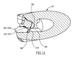
インサート頂面48は、外周頂縁54を有する。頂縁54は、ワークピース上で作動するように構成された正確に3つの作動部分56を含む。以下でさらに開示されるように、各作動部分56は、例えば、主切れ刃58、コーナー切れ刃60、および/または傾斜切れ刃62を含むことができる。各作動部分56は、また、材料を除去するためではなく、むしろワークピースの表面品質を円滑化または改善するために構成されたワイパー縁部64を含むこともできる。インサート頂面48は、インサート14の側面図(図4および図9)において、頂縁54を越えて突出する少なくとも1つの当接突出部55を含むことができる。突出部は、中間面MPに関して、インサート頂面48の任意の他の部分よりもさらに外側に延在する。各当接突出部55は、偏向面、または偏向器57を含む。
Insert top surface 48 has a circumferential
各主切れ刃58は、2~4mmの範囲の主切れ刃長さCELを有することができる。 Each main cutting edge 58 can have a main cutting edge length CEL in the range of 2 to 4 mm.
インサート頂面48は、インサート14をポケット18内に固定するためのねじ74と当接係合するように構成された頂部当接面68を含む。各頂部当接面68は、ねじ74と係合するように構成された正確に3つの頂部当接サブ面76を含む。頂部当接面68は、その上面図(図5および図10)において三角形の形状を有することができる。頂部当接面68は、インサート14の向きに対するねじ74の向きに応じて、また次に、切削工具12に対するインサート14の向きに応じて(例えば、図10に見られるように)、インサート頂面48に対して中心軸CAの周りで回転させることができる。
Insert top surface 48 includes a top abutment surface 68 configured to abuttingly engage
インサート頂面48は、主すくい面70を含む。各主すくい面70は、頂縁54と当接突出部55との間に配置することができる。各主すくい面70は、それぞれの主切れ刃58から延在し、当接突出部55上のそれぞれの偏向器57と合流することができる。換言すれば、各偏向器57は、それぞれのすくい面70よりも中心軸CAから遠くに位置し、頂部当接面68よりも中間面MPに近くに位置する。
Insert top surface 48 includes a main rake surface 70 . Each major rake face 70 may be disposed between the
図5および図10に注目する。本実施形態によれば、インサート頂面48の上面図または平面図において、インサート14は、例えば、正三角形でない形状を有することも、あるいは正三角形の形状を有することもできる。内接円ICは、頂縁54の3つの同一の主切れ刃58の間に画定される(または接する)。内接円ICは、2.5~3.8mmの範囲、好ましくは2.5~3.2mmの範囲の内接円直径ICDを有する。
Attention is directed to FIGS. 5 and 10. According to this embodiment, insert 14 can have a non-equilateral triangular shape or can have an equilateral triangular shape, for example, in a top or plan view of insert top surface 48 . The inscribed circle IC is defined between (or tangent to) three identical main cutting edges 58 of the
上述の内接円直径ICDの範囲は、適切で機能的クランプ孔(すなわち、使用可能なねじ頭部サイズを有する適切/使用可能なねじを収容することができる)のための余地を残さないが、それでも、適切なインサート構造を維持する。換言すれば、小さすぎるインサートは、弱くなりすぎて使用不能になる可能性があり、および/またはクランプ孔は、小さすぎて切削インサートをポケット内に固定するのに適していないねじのみを収容することになる。したがって、これらのインサート14は、クランプ孔、および他のいずれの開口部をも有さず、したがって、「孔なし」であると見なされる。クランプ孔を有さないことは、少なくとも、インサートがより堅牢であるために有利であり、製造プロセスは、孔を有するインサートと比較して安価である(粉末をプレスすることにより、貫通クランプ孔を作成するための余分なパンチが不要である)。 Although the range of inscribed circle diameter ICD mentioned above leaves no room for a suitable functional clamping hole (i.e. capable of accommodating a suitable/usable screw with a usable screw head size) , yet maintain proper insert structure. In other words, an insert that is too small may become too weak to be used, and/or the clamping hole only accommodates a screw that is too small to be suitable for securing the cutting insert within the pocket. It turns out. Therefore, these inserts 14 do not have clamp holes or any other openings and are therefore considered "holeless." Not having clamp holes is advantageous, at least because the inserts are more robust, and the manufacturing process is cheaper compared to inserts with holes (by pressing the powder, the through-clamp holes can be made (no extra punch needed to create one).
インサート底面50は、底部当接面78を含む。底部当接面78は、好ましくは平坦である。インサート底面50は、単一の平面内に位置することができる底縁80を有する。底縁80は、いかなる種類の機械加工または切削に対しても構成されない。したがって、インサート14は片面または一面である。インサート底面50は、底部当接面78の中央に位置する凹部を含むことができ、これにより、底部当接面78とポケット18内のそれぞれの当接面との間の係合規定(当分野で知られるような三点係合)を改善することができる。
Insert bottom surface 50 includes a bottom abutment surface 78 . Bottom abutment surface 78 is preferably flat. Insert bottom surface 50 has a
インサート外周面52は、頂縁54から延在し、底縁80に向かって(中心軸CAに近づくにつれて)収束する。さらに、インサート頂面48の上面図(図5および図10)では、底縁80のいかなる部分も見えない。したがって、インサート14は、当分野ではポジティブインサート14として、またはポジティブ切削形状を有するインサートとして知られているように、画定される。これらの小型インサートは、特にこれらのインサートが所定の大きさにプレス加工された幾何学的形状および切れ刃を有するので、製造およびプレスがより簡単なポジティブな切削幾何学的形状を有する。
The insert outer circumferential surface 52 extends from the
したがって、小型インサート14は、凹部、窪み、および他の構成を備えた頂面および/または底面を有し得るが、クランプ要素が通過し、かつインサートをポケットに固定することのできる貫通孔を欠いている限り、依然として「孔なし」と考えられることに留意されたい。 Thus, the miniature insert 14 may have a top and/or bottom surface with recesses, indentations, and other features, but lacks through holes through which the clamping element can pass and secure the insert in the pocket. Note that it is still considered "non-perforated" as long as the
図1~図5に注目する。第一のインサートの実施形態によれば、小型インサート14は、当分野で知られているような高送り切削インサート114である。各作動部分156は、(図5に見られるように、インサート頂面148の平面図において)コーナー切れ刃160に接続されている主切れ刃158に横方向に接続された傾斜切れ刃162を含む。作動部分156は、傾斜切れ刃162と主切れ刃158とを接続する副コーナー切れ刃166を含むことができる。各傾斜切れ刃162は、傾斜すくい面184と傾斜逃げ面186との間の交点に形成される。各主切れ刃158は、主すくい面170と主逃げ面172との交点に形成される。主逃げ面172は、好ましくは平坦であり、また、以下に説明するように、磁気位置決め工具16のインサート保持面28およびポケットのそれぞれの壁と当接するように構成される。各コーナー切れ刃160は、コーナーすくい面188とコーナー逃げ面190との交点に形成される。すくい面のそれぞれは、インサート頂面148上に形成される。逃げ面のそれぞれは、インサート外周面152に形成される。
Pay attention to FIGS. 1 to 5. According to a first insert embodiment, the miniature insert 14 is a high
第一のインサートの実施形態によれば、主切れ刃長さCELは2.5mmに等しく、内接円直径ICDは3.0mmに等しい。 According to the first insert embodiment, the main cutting edge length CEL is equal to 2.5 mm and the inscribed circle diameter ICD is equal to 3.0 mm.
図6~図10に注目する。第二のインサートの実施形態によれば、小型インサート14は、当分野で知られているように、ショルダリングインサート214である。ショルダリングインサートは、1~2°の公差内でワークピース内の直角肩部をフライス加工するように構成されている。各作動部分256は、主切れ刃258と、ワイパー刃264と、それらの間に延在するコーナー切れ刃260とを含む。各作動部分256は、また、ワイパー刃264と隣接する作動部分256の主切れ刃258との間に延在する傾斜切れ刃262を含むことができる。換言すれば、第一の作動部分256の傾斜切れ刃262は、隣接する第二の作動部分256の主切れ刃258の一部であり、同じ向きを有し、連続している。したがって、用途によって、より深い肩部が必要とされる場合、「延長された主切れ刃」258は、単に、より深い切削深さを画定することによって達成することができる。このような場合、オペレータは、第一の作動部分256の傾斜切れ刃262と第二の作動部分256の主切れ刃258との合計長さ全体を使用することを決定して、前記延長された主切れ刃258を達成することができる。各主切れ刃258は、主すくい面270と主逃げ面272との交点に形成される。各傾斜切れ刃262は、傾斜すくい面284と傾斜逃げ面286との間の交点に形成される。各コーナー切れ刃260は、コーナーすくい面288とコーナー逃げ面290との交点に形成される。すくい面のそれぞれは、インサート頂面248上に形成される。逃げ面のそれぞれは、インサート外周面252に形成される。外周面252は、ワイパー逃げ面265をさらに含み、そのそれぞれは、それぞれのワイパー刃264から延在する。外周面252は、各主逃げ面272の間を底縁80に向かって延在する側部当接面253をさらに含む。
Attention is paid to FIGS. 6 to 10. According to a second insert embodiment, the miniature insert 14 is a shouldering
第二のインサートの実施形態によれば、主切れ刃長さCELは2.8mmに等しく、内接円直径ICDは2.8mmに等しい。 According to the second insert embodiment, the main cutting edge length CEL is equal to 2.8 mm and the inscribed circle diameter ICD is equal to 2.8 mm.
図1および図6に注目する。切削工具12は、切削本体91と、そこから延在し、少なくとも2つのポケット18を含む切削部分92とを有する。1つまたは複数のポケット18は、半径方向に向けられたポケットまたは半径方向ポケット18として当分野で知られているものである。したがって、インサート14は、半径方向インサートとも呼ばれる。
Attention is directed to FIGS. 1 and 6. Cutting
各ポケット18は、ポケット基部表面93と、そこから延在する2つのポケット壁94とを有することができる。ポケット壁94は、ポケット基部表面93に対して垂直にすることもできる。第一のインサートの実施形態によれば、2つのポケット壁194は、(図1に見られるように)回転軸Aにほぼ平行な方向に内側に収束する。第二のインサート214の実施形態によれば、2つのポケット壁294は、(図6に見られるように)回転軸Aに直角な方向に内側に収束する。
Each
各ポケット18は、これらの小型の孔なしインサート14を固定するくさび型配置を含む。インサート14は、インサート14自体のシンプルで迅速で費用対効果の高い交換または割出し(アダプタまたはシムなしで)を保証するために、切削工具12または任意の種類のアダプタ/カートリッジの任意の他の部分に、いかなる方法でも接着されることも、あるいはろう付けされることもない。各ポケット18は、インサート14を通すことなく、切削工具12内のねじ孔95にねじ込まれるねじ74を含む。ねじ孔95は、ポケット基部表面93には配置されていない。ねじ74は、インサート14に直接接触し、ポケット基部表面93に対してインサート14を押し付けるように構成される(すなわち、インサート14は、それらの間にくさび留めされる)。ねじ74は、また、インサート14を、ポケット18内にインサート14を配置するポケット壁94に向かって、それに対して引っ張る。第一のインサートの実施形態によれば、少なくとも1つの主逃げ面172は、それぞれのポケット壁194に当接する。第二のインサートの実施形態によれば、少なくとも1つの側部当接面253は、それぞれのポケット壁294に当接する。ねじ74を締めると、ねじ74は頂部当接面68に係合し、具体的には、ねじ74は、頂部当接サブ面76のうちの1つに当接する。
Each
各ポケット18は、切削本体91に沿って延在し、流体出口98でポケット18に開口する内部流体チャネル96をさらに含むことができる。流体出口は、ねじ孔95に隣接して配置することができる。流体チャネル96および流体出口98は、ねじ孔95から分離されている。流体チャネル96は、2つのポケット壁94の間に配置することができる。
Each
トルクドライバは周知であり、ときどき、本分野の工具(すなわち、小さなねじを含むミニ切削工具)とともに使用するために供給/推奨される。というのも、前記小径のファスナは、かなり容易に損傷することも、あるいは破損することもあるからである。これらのトルクドライバは、それぞれのねじサイズにトルクを加えるとき、オペレータが推奨トルク限界を超えることを防止するように較正されたトルク制限機構を含む。 Torque drivers are well known and are sometimes supplied/recommended for use with tools in the art (ie, mini cutting tools containing small screws). This is because such small diameter fasteners can be damaged or broken rather easily. These torque drivers include a torque limiting mechanism that is calibrated to prevent the operator from exceeding recommended torque limits when applying torque to the respective screw size.
標準/正規ドライバ42、すなわちトルクドライバは、対向するドライバ前端部43および後端部44と、それらの間に延在するドライバ本体46とを含む。ドライバ42は、ドライバ回転軸DRAを有する。ドライバ前端部43は、TORX(登録商標)のようなキーまたはトルク伝達形状を含む。ドライバ本体46は、把持を提供するように構成されたドライバ保持部分30を含む。ドライバ保持部分30は、その2つの対向する側面の一方または両方のいずれかで、ドライバ回転軸DRAから離れる方向に半径方向外側に延在することができる。
Standard/
(通常、全ての切れ刃が摩耗したために)小型インサート14、114、214を磁気位置決め工具16、116、216、316に交換する方法は、以下のステップ、すなわち、
a.インサート保持面28を小型インサート14、114、214の任意の部分に取り付けるステップと、
b.ねじ74を緩めて、小型インサート14、114、214をアンクランプまたは解放するステップと、
c.インサート14、114、214をポケット18から引き出し、インサート14、114、214をインサート保持面28から取り外し、それを廃棄するステップと、
d.インサート保持面28を、交換用切削インサート14、114、214の未使用主逃げ面172または側部当接面253に取り付けるステップと、
e.交換用インサート14、114、214をポケット18に挿入し、ねじ74を締めるステップと、
を含むことができる。
The method of replacing a
a. attaching the
b. unclamping or releasing the
c. withdrawing the
d. attaching the
e. inserting the
can include.
磁気位置決め工具16、116、216、316を用いて、(通常、摩耗した切れ刃に起因して)小型インサート14、114、214を割り出す方法は、以下のステップ、すなわち、
a.磁気保持面28を、通常は摩耗した作動主切れ刃58、158、258に関連する露出した、もしくはアクセス可能な主逃げ面172、または側部当接面253に取り付けるステップと、
b.ねじ74を緩めて、小型インサート14、114、214をアンクランプまたは解放するステップと、
c.磁気工具16、116、216、316をインサート14、114、214に取り付けるステップと、
d.インサート14、114、214をポケット18から取り外し、未使用主逃げ面172、272がインサート保持面28に取り付けられるように、インサートを割り出すステップと、
e.小型インサート14をポケット18に挿入し、ねじ74を締めるステップと、
を含むことができる。
A method for indexing
a. attaching the
b. unclamping or releasing the
c. attaching a
d. removing the
e. inserting the small insert 14 into the
can include.
Claims (13)
前記切削インサート(14)は、対向するインサート頂面及び底面(48、148、248、50)を備え、
前記インサート頂面は、正確に3つの作動部分(56)を順番に含む外周頂縁(54)を有し、
各作動部分(56)は、正確に3つの主切れ刃(58、158、258)の1つを有し、
前記切削インサート(14、114、214)は、全ての主切れ刃(58、158、258)のみと接線接触する内接円(IC)を有し、
前記内接円(IC)は、3.8mm未満の内接円直径(ICD)を有し、
前記切削インサート(14、114、214)は、前記切削インサート(14、114、214)の側面図において前記頂縁(54)を越えて突出する少なくとも1つの当接突出部(55)を有し、
前記当接突出部(55)は、主すくい面(170、270)から延在しチップを偏向させるように構成された偏向器(57)を有し、
前記切削インサート(14、114、214)は、PCD製又はPCB製ではなく超硬合金から作られており、
前記インサート頂面(48、148、248)は、正確に3つの頂部当接サブ面(76)を含む頂部当接面(68)を有し、
各々隣接する3つの頂部当接サブ面(76)は、段の不連続性を有する、切削インサート。 A small indexable cutting insert (14, 114, 214) without a through hole,
The cutting insert (14) includes opposing insert top and bottom surfaces (48, 148, 248, 50),
said insert top surface has a circumferential top edge (54) containing exactly three actuating portions (56) in sequence;
Each working part (56) has exactly one of the three main cutting edges (58, 158, 258);
The cutting insert (14, 114, 214) has an inscribed circle (IC) that is in tangential contact only with all main cutting edges (58, 158, 258);
the inscribed circle (IC) has an inscribed circle diameter (ICD) of less than 3.8 mm;
The cutting insert (14, 114, 214) has at least one abutment protrusion (55) projecting beyond the top edge (54) in a side view of the cutting insert (14, 114, 214). ,
The abutment protrusion (55) has a deflector (57) extending from the main rake face (170, 270) and configured to deflect the chip;
The cutting insert (14, 114, 214) is made of cemented carbide rather than PCD or PCB;
The insert top surface (48, 148, 248) has a top abutment surface (68) that includes exactly three top abutment sub-surfaces (76);
A cutting insert in which each of the three adjacent top abutment sub-surfaces (76) has a step discontinuity .
前記対向するインサート頂面及び底面(48、148、248、50)の間に延在するインサート外周面(52)と、
前記インサート頂面及び底面(48、148、248、50)を通る対称中心軸(CA)と、
前記対称中心軸(CA)に平行な測定で1~2.5mmの範囲にある最大インサート厚さ(MIT)と、
を備える、請求項1又は2に記載の切削インサート(14、114、214)。 The cutting insert (14, 114, 214) is
an insert outer peripheral surface (52) extending between the opposing insert top and bottom surfaces (48, 148, 248, 50);
a central axis of symmetry (CA) passing through the insert top and bottom surfaces (48, 148, 248, 50);
a maximum insert thickness (MIT) ranging from 1 to 2.5 mm measured parallel to the central axis of symmetry (CA);
A cutting insert (14, 114, 214) according to claim 1 or 2, comprising:
前記対向するインサート頂面及び底面(48、148、248、50)の間に延在するインサート外周面(52)と、
前記頂面及び底面(48、148、248、50)を通る対称中心軸(CA)と、を備え、
前記切削インサート(14)は、前記対称中心軸(CA)に関して120°の回転対称性を有する、請求項1~4の何れか一項に記載の切削インサート(14、114、214)。 The cutting insert (14, 114, 214) is
an insert outer peripheral surface (52) extending between the opposing insert top and bottom surfaces (48, 148, 248, 50);
a central axis of symmetry (CA) passing through the top surface and the bottom surface (48, 148, 248, 50),
Cutting insert (14, 114, 214) according to any one of claims 1 to 4, wherein the cutting insert (14) has a rotational symmetry of 120° about the central axis of symmetry (CA).
前記インサート頂面(48)の平面図では、前記底縁(80)のいかなる部分も見えない、請求項1~5の何れか一項に記載の切削インサート(14、114、214)。 The opposing insert top and bottom surfaces (48, 148, 248, 50) include top and bottom edges (54, 80);
A cutting insert (14, 114, 214) according to any of the preceding claims, wherein no part of the bottom edge (80) is visible in a plan view of the insert top surface (48).
前記インサート底面(50)は、機械加工用に構成されておらず、切れ刃を備えない底縁(80)を備える、請求項1~7の何れか一項に記載の切削インサート(14、114、214)。 the cutting insert (14, 114, 214) is single-sided and positive;
Cutting insert (14, 114) according to any one of claims 1 to 7 , wherein the insert bottom surface (50) is not configured for machining and comprises a bottom edge (80) without cutting edges. , 214).
前記切削インサート(14、114、214)を固定するように構成され、寸法決めされたインサートポケット(18)と、
を備える、切削工具(12)。 The cutting insert (14, 114, 214) according to any one of claims 1 to 10 ,
an insert pocket (18) configured and dimensioned to secure said cutting insert (14, 114, 214);
A cutting tool (12) comprising:
a.位置決め工具(16、116、216、316)を提供するステップと、
b.通常は摩耗した作動主切れ刃(58、158、258)に関連する露出した若しくはアクセス可能な主逃げ面(172)、又は、側部当接面(253)をインサート保持面(28)と接触させ、それによって前記切削インサート(14、114、214)を維持するステップと、
c.前記クランプねじ(74)を緩めて、前記切削インサート(14、114、214)を前記インサートポケット(18)から解放するステップと、
d.前記切削インサート(14、114、214)を前記位置決め工具(16、116、216、316)で前記ポケット(18)から取り外し、前記切削インサート(14、114、214)を手で割出し又は交換して、未使用切れ刃の主逃げ面(72、172、272)が前記インサート保持面(28)に取り付けられ、それによって維持されるようにするステップと、
e.前記位置決め工具(16、116、216、316)で前記割出し又は交換された切削インサート(14、114、214)を前記ポケット(18)に挿入するステップと、
f.前記クランプねじ(74)を締めて、前記切削インサート(14、114、214)を前記インサートポケット(18)に固定するステップと、
を含む、方法。 A small holeless indexable cutting insert (14, 114, 214) externally fixed in the insert pocket (18) of the cutting tool (10) according to claim 11 or 12 by means of a clamping screw (74). A method of indexing or exchanging, the method comprising:
a. providing a positioning tool (16, 116, 216, 316);
b. Contacting the exposed or accessible main flank (172) or side abutment surface (253) associated with the normally worn working main cutting edge (58, 158, 258) with the insert retaining surface (28) and thereby maintaining said cutting insert (14, 114, 214);
c. loosening the clamp screw (74) to release the cutting insert (14, 114, 214) from the insert pocket (18);
d. removing said cutting insert (14, 114, 214) from said pocket (18) with said positioning tool (16, 116, 216, 316) and manually indexing or replacing said cutting insert (14, 114, 214); the main flank surface (72, 172, 272) of the unused cutting edge is attached to and retained thereby by the insert retaining surface (28);
e. inserting the indexed or replaced cutting insert (14, 114, 214) with the positioning tool (16, 116, 216, 316) into the pocket (18);
f. tightening the clamp screw (74) to secure the cutting insert (14, 114, 214) in the insert pocket (18);
including methods.
Applications Claiming Priority (3)
| Application Number | Priority Date | Filing Date | Title |
|---|---|---|---|
| US201762572611P | 2017-10-16 | 2017-10-16 | |
| US62/572,611 | 2017-10-16 | ||
| PCT/IL2018/051036 WO2019077597A1 (en) | 2017-10-16 | 2018-09-16 | Cutting tool and undersized bore-less indexable insert therefor |
Publications (3)
| Publication Number | Publication Date |
|---|---|
| JP2020536751A JP2020536751A (en) | 2020-12-17 |
| JP2020536751A5 JP2020536751A5 (en) | 2021-10-21 |
| JP7344868B2 true JP7344868B2 (en) | 2023-09-14 |
Family
ID=63832465
Family Applications (1)
| Application Number | Title | Priority Date | Filing Date |
|---|---|---|---|
| JP2020517880A Active JP7344868B2 (en) | 2017-10-16 | 2018-09-16 | Small holeless indexable inserts for cutting tools and cutting tools |
Country Status (10)
| Country | Link |
|---|---|
| US (1) | US11241747B2 (en) |
| EP (1) | EP3697560A1 (en) |
| JP (1) | JP7344868B2 (en) |
| KR (1) | KR102582913B1 (en) |
| CN (1) | CN111212701B (en) |
| BR (1) | BR112020007392A2 (en) |
| CA (1) | CA3078338A1 (en) |
| IL (1) | IL273410B2 (en) |
| TW (1) | TWI763912B (en) |
| WO (1) | WO2019077597A1 (en) |
Families Citing this family (1)
| Publication number | Priority date | Publication date | Assignee | Title |
|---|---|---|---|---|
| RU2726516C1 (en) * | 2020-01-21 | 2020-07-14 | Нина Алексеевна Корюкина | Assembled cutting tool |
Citations (3)
| Publication number | Priority date | Publication date | Assignee | Title |
|---|---|---|---|---|
| JP2003127007A (en) | 2001-08-10 | 2003-05-08 | Sumitomo Electric Ind Ltd | Throw-away tip |
| JP2009534210A (en) | 2006-04-24 | 2009-09-24 | バレナイト リミティド ライアビリティ カンパニー | Side locking insert and material removal tool using side locking insert |
| JP2013502328A (en) | 2009-08-21 | 2013-01-24 | セラムテック ゲゼルシャフト ミット ベシュレンクテル ハフツング | Precision pressing and sintering of cutting inserts, especially throw-away type cutting inserts |
Family Cites Families (50)
| Publication number | Priority date | Publication date | Assignee | Title |
|---|---|---|---|---|
| US3805349A (en) * | 1970-03-30 | 1974-04-23 | Sumitomo Electric Industries | Throw-away insert for milling cutter |
| DE2553298A1 (en) * | 1975-11-27 | 1977-06-08 | Erhard Morgner | External machining rotary tool - has adjustable tension head eccentrically fitted in steel holder shaft using hexagonal spanner |
| US4297058A (en) * | 1980-06-30 | 1981-10-27 | Kennametal Inc. | Indexable cutting insert |
| JPS59140105U (en) * | 1983-03-11 | 1984-09-19 | 住友電気工業株式会社 | Throwaway tip |
| EP0130268A1 (en) * | 1983-07-05 | 1985-01-09 | GFM Gesellschaft für Fertigungstechnik und Maschinenbau Gesellschaft m.b.H. | Cutter head |
| CH652063A5 (en) * | 1984-01-09 | 1985-10-31 | Willi Sandmeier | Process for re-machining exchangeable cutting inserts which are in the form of a plate and are intended for a chip-removing tool, and cutting insert re-machined in accordance with the process |
| DE3506415A1 (en) | 1985-02-23 | 1986-09-04 | Stellram GmbH, 6056 Heusenstamm | Screwdriver |
| KR920010888B1 (en) * | 1985-03-30 | 1992-12-21 | 미쓰비시 마테리알 가부시기가이샤 | Insert rotary cutter |
| US4596166A (en) * | 1985-05-22 | 1986-06-24 | Lindsay Harold W | End milling cutter and method of making same |
| SE459237B (en) | 1987-10-26 | 1989-06-19 | Sandvik Ab | TRIBUTES BEFORE PLANNING |
| US5437522A (en) * | 1991-09-06 | 1995-08-01 | Iscar Ltd. | Milling cutter with overlapping edge insert |
| JPH06126572A (en) * | 1992-10-22 | 1994-05-10 | Toshiba Tungaloy Co Ltd | Apparatus for automatically changing cutting edge tip of milling tool |
| JPH06182605A (en) * | 1992-12-18 | 1994-07-05 | Hitachi Ltd | Throw-away tip with projection |
| IT230444Y1 (en) * | 1993-10-01 | 1999-06-07 | Omus S P A In Amministrazione | PERFECTED CUTTING INSERT FOR REAMERS |
| EP0661122A1 (en) * | 1993-12-27 | 1995-07-05 | Plansee Tizit Gesellschaft M.B.H. | Removable cutting insert |
| SE511550C2 (en) | 1996-10-17 | 1999-10-18 | Seco Tools Ab | Tools and cutters for milling |
| SE510851C2 (en) * | 1996-12-23 | 1999-06-28 | Sandvik Ab | Cuts and holders for cutting metalworking |
| JPH11156607A (en) * | 1997-11-28 | 1999-06-15 | Sumitomo Electric Ind Ltd | Cutting tool |
| SE518855C2 (en) * | 1998-03-10 | 2002-11-26 | Seco Tools Ab | Cutting tools and cutting tools |
| IL129665A (en) * | 1999-04-29 | 2008-06-05 | Rafael Morgulis | Cutting tool assembly and cutting insert therefor |
| US6488450B2 (en) * | 2001-01-22 | 2002-12-03 | Ingersoll Cutting Tool Company | T-slot milling cutter and insert therefor |
| EP1435271A4 (en) | 2001-08-10 | 2008-03-26 | Sumitomo Electric Industries | Ultra high-pressure sintered cutter with recess or groove, holding mechanism for the cutter, and method of manufacturing the cutter |
| SE525829C2 (en) | 2002-06-26 | 2005-05-10 | Seco Tools Ab | Double sided inserts with bombed bisk cutting edge and manufacturing method for the insert |
| US6918746B2 (en) * | 2003-04-25 | 2005-07-19 | Electro-Motive Diesel, Inc. | Diesel engine water pump with thrust bearing preload |
| US7001115B2 (en) * | 2003-07-21 | 2006-02-21 | Kennametal Inc. | Cutting insert and toolholder for holding the same |
| US7189031B2 (en) * | 2003-12-11 | 2007-03-13 | Kennametal Inc. | Toolholder with insert clamp and method for the same |
| US20050271483A1 (en) | 2004-06-02 | 2005-12-08 | Sandvik Ab | Indexable cutting inserts and methods for producing the same |
| US7278805B2 (en) | 2005-10-03 | 2007-10-09 | Kennametal Inc. | Cutting insert for effective chip control |
| JP4609304B2 (en) * | 2005-12-19 | 2011-01-12 | 三菱マテリアル株式会社 | Insert peripheral grinding method and peripheral grinding apparatus |
| SE530780C2 (en) * | 2006-01-10 | 2008-09-09 | Sandvik Intellectual Property | Indexable cutting with different release angles and turning tools |
| SE530090C2 (en) | 2006-06-27 | 2008-02-26 | Sandvik Intellectual Property | Flat cutter inserts with several arcuate delegates and convex release surfaces |
| BRPI0813258A2 (en) | 2007-06-21 | 2014-12-30 | Ceramtec Ag | FREE DOUBLE POSITIVE NEGATIVE SURFACE CUTTING BOARD |
| FR2928284B1 (en) * | 2008-03-10 | 2010-06-04 | Safety Production | "CHIP DEFLECTOR CUTTING PLATE" |
| IL199285A (en) * | 2009-06-11 | 2012-12-31 | Iscar Ltd | Cutting insert and cutting tool therefor |
| KR101107444B1 (en) * | 2009-06-10 | 2012-01-19 | 대구텍 유한회사 | Cutting tool and cutting insert for the same |
| KR20120020153A (en) * | 2009-06-16 | 2012-03-07 | 가부시키가이샤 탕가로이 | Cutting insert and indexable face milling cutter |
| IL200063A (en) * | 2009-07-26 | 2014-01-30 | Iscar Ltd | Cutting insert and rotary cutting tool |
| IL206272A (en) * | 2010-06-07 | 2014-08-31 | Iscar Ltd | Cutting insert and milling tool |
| CN103124609B (en) * | 2010-09-27 | 2015-08-19 | 株式会社钨钛合金 | Cutting tip and cutting element |
| KR101928112B1 (en) * | 2010-12-31 | 2018-12-11 | 다이아몬드 이노베이션즈, 인크. | Method of producing holes and countersinks in polycrystalline bodies |
| IL211444A0 (en) * | 2011-02-27 | 2011-06-30 | Kennametal Inc | High feed cutting insert |
| AT12700U1 (en) * | 2011-07-05 | 2012-10-15 | Ceratizit Austria Gmbh | DRILL CUTTING INSERT |
| FR2979555B1 (en) * | 2011-09-01 | 2013-09-27 | Safety | CLAMP SCREW WITH POSITIVE FOOTPRINT |
| DK2763809T3 (en) * | 2011-10-06 | 2020-09-07 | Ceram Gmbh | MINIATURE CUTTING PLATE |
| SE536345C2 (en) * | 2012-01-20 | 2013-09-03 | Sandvik Intellectual Property | Hole cutting tools with interchangeable cutting tools including male and female securing means |
| JP5878086B2 (en) | 2012-06-21 | 2016-03-08 | 住友電工ハードメタル株式会社 | Cutting tool manufacturing method |
| EP3254790A1 (en) * | 2012-09-27 | 2017-12-13 | Tungaloy Corporation | Cutting insert and rotary cutting tool with such an insert |
| US9481038B2 (en) | 2013-12-11 | 2016-11-01 | Iscar, Ltd. | Cutting insert having a dovetail anti-slip arrangement |
| DE102015108902B3 (en) | 2015-06-05 | 2016-07-07 | Kennametal Inc. | reamer |
| US10076795B2 (en) * | 2015-11-19 | 2018-09-18 | Iscar, Ltd. | Triangular tangential milling insert and milling tool |
-
2018
- 2018-08-21 US US16/106,310 patent/US11241747B2/en active Active
- 2018-08-28 TW TW107129881A patent/TWI763912B/en active
- 2018-09-16 CN CN201880067154.9A patent/CN111212701B/en active Active
- 2018-09-16 JP JP2020517880A patent/JP7344868B2/en active Active
- 2018-09-16 BR BR112020007392-0A patent/BR112020007392A2/en not_active Application Discontinuation
- 2018-09-16 WO PCT/IL2018/051036 patent/WO2019077597A1/en unknown
- 2018-09-16 CA CA3078338A patent/CA3078338A1/en active Pending
- 2018-09-16 KR KR1020207012521A patent/KR102582913B1/en active IP Right Grant
- 2018-09-16 EP EP18785454.2A patent/EP3697560A1/en active Pending
- 2018-09-16 IL IL273410A patent/IL273410B2/en unknown
Patent Citations (3)
| Publication number | Priority date | Publication date | Assignee | Title |
|---|---|---|---|---|
| JP2003127007A (en) | 2001-08-10 | 2003-05-08 | Sumitomo Electric Ind Ltd | Throw-away tip |
| JP2009534210A (en) | 2006-04-24 | 2009-09-24 | バレナイト リミティド ライアビリティ カンパニー | Side locking insert and material removal tool using side locking insert |
| JP2013502328A (en) | 2009-08-21 | 2013-01-24 | セラムテック ゲゼルシャフト ミット ベシュレンクテル ハフツング | Precision pressing and sintering of cutting inserts, especially throw-away type cutting inserts |
Non-Patent Citations (1)
| Title |
|---|
| 住友電工ハードメタル株式会社,イゲタロイ切削工具,日本,2008年,B108頁 |
Also Published As
| Publication number | Publication date |
|---|---|
| KR102582913B1 (en) | 2023-09-26 |
| WO2019077597A1 (en) | 2019-04-25 |
| RU2020110466A3 (en) | 2022-01-12 |
| CN111212701A (en) | 2020-05-29 |
| RU2020110466A (en) | 2021-11-18 |
| IL273410B1 (en) | 2023-12-01 |
| CN111212701B (en) | 2023-05-12 |
| TW201922382A (en) | 2019-06-16 |
| US20190111494A1 (en) | 2019-04-18 |
| JP2020536751A (en) | 2020-12-17 |
| IL273410A (en) | 2020-05-31 |
| CA3078338A1 (en) | 2019-04-25 |
| KR20200067166A (en) | 2020-06-11 |
| EP3697560A1 (en) | 2020-08-26 |
| BR112020007392A2 (en) | 2020-09-29 |
| TWI763912B (en) | 2022-05-11 |
| US11241747B2 (en) | 2022-02-08 |
| IL273410B2 (en) | 2024-04-01 |
Similar Documents
| Publication | Publication Date | Title |
|---|---|---|
| US10005132B2 (en) | Cutting tool and cutting insert having exactly three cutting portions therefor | |
| CA2891295C (en) | Cutting tool and cutting insert with a rearward resilience slit | |
| CA2636356C (en) | Cutting tool | |
| JP7227262B2 (en) | Milling kit containing boreless indexable inserts and positioning tools with insert retaining surfaces | |
| EP1415742B1 (en) | Indexible turning tool for chipforming machining | |
| CA2880173A1 (en) | Cutting tool and cutting insert with a stopper surface | |
| JP2022541989A (en) | Insert adaptor and turning tool with insert adaptor | |
| JP7344868B2 (en) | Small holeless indexable inserts for cutting tools and cutting tools | |
| WO2013105081A1 (en) | Cutting insert having hole orientation indicia and method for making thereof | |
| WO2008051161A1 (en) | Cutting portion with a friction surface cooperating with a wrench | |
| EP2536521A1 (en) | Cutting insert and cutting tool | |
| RU2777388C2 (en) | Cutting tool, and reduced indexed insert without holes for it | |
| RU2773752C2 (en) | Milling set containing indexed insert without holes and positioning device with surface for insert retention | |
| GB2332161A (en) | Reuse of disposable cutter inserts | |
| JP2001009617A (en) | Throwaway cutting tool | |
| JPH10128612A (en) | Edge part replacing type end mill | |
| JP2003340611A (en) | Throw-away cutting tool for bore machining |
Legal Events
| Date | Code | Title | Description |
|---|---|---|---|
| RD03 | Notification of appointment of power of attorney |
Free format text: JAPANESE INTERMEDIATE CODE: A7423 Effective date: 20200424 |
|
| RD04 | Notification of resignation of power of attorney |
Free format text: JAPANESE INTERMEDIATE CODE: A7424 Effective date: 20200424 |
|
| A521 | Request for written amendment filed |
Free format text: JAPANESE INTERMEDIATE CODE: A523 Effective date: 20210913 |
|
| A621 | Written request for application examination |
Free format text: JAPANESE INTERMEDIATE CODE: A621 Effective date: 20210913 |
|
| A977 | Report on retrieval |
Free format text: JAPANESE INTERMEDIATE CODE: A971007 Effective date: 20220815 |
|
| A131 | Notification of reasons for refusal |
Free format text: JAPANESE INTERMEDIATE CODE: A131 Effective date: 20220825 |
|
| A521 | Request for written amendment filed |
Free format text: JAPANESE INTERMEDIATE CODE: A523 Effective date: 20221124 |
|
| A02 | Decision of refusal |
Free format text: JAPANESE INTERMEDIATE CODE: A02 Effective date: 20230310 |
|
| A521 | Request for written amendment filed |
Free format text: JAPANESE INTERMEDIATE CODE: A523 Effective date: 20230629 |
|
| A911 | Transfer to examiner for re-examination before appeal (zenchi) |
Free format text: JAPANESE INTERMEDIATE CODE: A911 Effective date: 20230706 |
|
| TRDD | Decision of grant or rejection written | ||
| A01 | Written decision to grant a patent or to grant a registration (utility model) |
Free format text: JAPANESE INTERMEDIATE CODE: A01 Effective date: 20230825 |
|
| A61 | First payment of annual fees (during grant procedure) |
Free format text: JAPANESE INTERMEDIATE CODE: A61 Effective date: 20230904 |
|
| R150 | Certificate of patent or registration of utility model |
Ref document number: 7344868 Country of ref document: JP Free format text: JAPANESE INTERMEDIATE CODE: R150 |